Proceedings of the International Association for Shell and Spatial Structures (IASS) Symposium 2009, Valencia Evolution and Trends in Design, Analysis and Construction of Shell and Spatial Structures 28 September – 2 October 2009, Universidad Politecnica de Valencia, Spain Alberto DOMINGO and Carlos LAZARO (eds.) ROLEX LEARNING CENTER in Lausanne: From conceptual design to execution Agnes WEILANDT, Manfred GROHMANN, Klaus BOLLINGER, Michael WAGNER Bollinger + Grohmann Ingenieure Westhafenplatz 1, 60327 Frankfurt, Germany [email protected] Abstract The architectural concept of the ROLEX LEARNING CENTER in Lausanne envisaged an architectural landscape which which allows a natural separation of the different zones of use. The resulting structural solutions were not only during the design process a challenge for the structural engineers but also during execution. This paper will therefore present the different partly unusual approaches found for the formwork and the reinforcement of the shells of the ROLEX LEARNING CENTER. Keywords: concrete shell, steel structure, execution planning, execution, formwork, scripting, automated design 1. Introduction The unusual architectural concept of the ROLEX LEARNING CENTER in Lausanne was for all participants a big challenge. Instead of dividing the building as usual by slabs and walls in horizontal and vertical direction the design concept envisaged an architectural landscape. This landscape consists of two shells with different spans and flat areas, which are placed in between the shells. In contrast to usual shell constructions these shells do not represent the roof of the building but the floor of the interior space. The one story high interior space covered by a steel roof and transparent glass facades. The architectural and structural concept of the building is described more in detail in Form finding of the shell structures of the ROLEX LEARNING CENTER in Lausanne, Grohmann et al .[2]. 640

Welcome message from author
This document is posted to help you gain knowledge. Please leave a comment to let me know what you think about it! Share it to your friends and learn new things together.
Transcript

Proceedings of the International Association for Shell and Spatial Structures (IASS) Symposium 2009, Valencia Evolution and Trends in Design, Analysis and Construction of Shell and Spatial Structures
28 September – 2 October 2009, Universidad Politecnica de Valencia, Spain Alberto DOMINGO and Carlos LAZARO (eds.)
ROLEX LEARNING CENTER in Lausanne: From conceptual design to execution
Agnes WEILANDT, Manfred GROHMANN, Klaus BOLLINGER, Michael WAGNER
Bollinger + Grohmann Ingenieure Westhafenplatz 1, 60327 Frankfurt, Germany
Abstract The architectural concept of the ROLEX LEARNING CENTER in Lausanne envisaged an architectural landscape which which allows a natural separation of the different zones of use. The resulting structural solutions were not only during the design process a challenge for the structural engineers but also during execution. This paper will therefore present the different partly unusual approaches found for the formwork and the reinforcement of the shells of the ROLEX LEARNING CENTER. Keywords: concrete shell, steel structure, execution planning, execution, formwork, scripting, automated design
1. Introduction The unusual architectural concept of the ROLEX LEARNING CENTER in Lausanne was for all participants a big challenge. Instead of dividing the building as usual by slabs and walls in horizontal and vertical direction the design concept envisaged an architectural landscape. This landscape consists of two shells with different spans and flat areas, which are placed in between the shells. In contrast to usual shell constructions these shells do not represent the roof of the building but the floor of the interior space. The one story high interior space covered by a steel roof and transparent glass facades. The architectural and structural concept of the building is described more in detail in Form finding of the shell structures of the ROLEX LEARNING CENTER in Lausanne, Grohmann et al .[2].
640
Proceedings of the International Association for Shell and Spatial Structures (IASS) Symposium 2009, Valencia Evolution and Trends in Design, Analysis and Construction of Shell and Spatial Structures
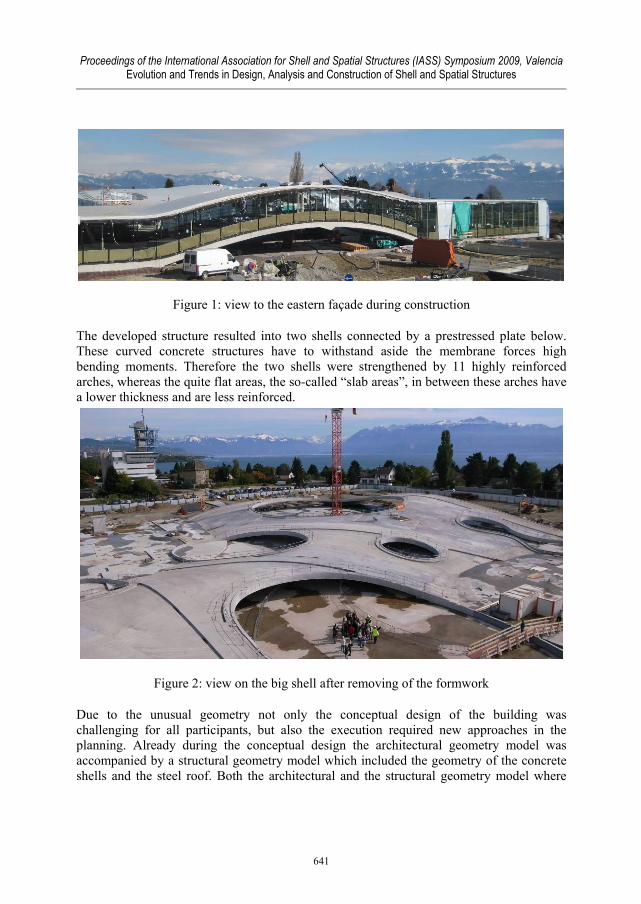
Figure 1: view to the eastern façade during construction
The developed structure resulted into two shells connected by a prestressed plate below. These curved concrete structures have to withstand aside the membrane forces high bending moments. Therefore the two shells were strengthened by 11 highly reinforced arches, whereas the quite flat areas, the so-called “slab areas”, in between these arches have a lower thickness and are less reinforced.
Figure 2: view on the big shell after removing of the formwork
Due to the unusual geometry not only the conceptual design of the building was challenging for all participants, but also the execution required new approaches in the planning. Already during the conceptual design the architectural geometry model was accompanied by a structural geometry model which included the geometry of the concrete shells and the steel roof. Both the architectural and the structural geometry model where
641

Proceedings of the International Association for Shell and Spatial Structures (IASS) Symposium 2009, Valencia Evolution and Trends in Design, Analysis and Construction of Shell and Spatial Structures
developed in further design process in parallel and served afterwards as base for the execution planning. The execution of the project was only possible due to the close and successful collaboration of all participants of the project including the executing companies. To ensure cost certainty the client decided already in an early stage of the project to engage the total contractor, Losinger, for the execution of the project. Since then the planning team was in close collaboration with the executing companies. This gave rise to develop partly unusual but favorable solutions for the execution of the concrete shells, which will be described more in detail in the following.
2. Execution planning of the shell structures The required services of structural engineers during a design process are normally well defined in the Building standards. But these definitions are achieving their limits for unusual projects as the ROLEX LEARNING CENTER in Lausanne. Which information a formwork drawing has to include in case of a free-formed surface, which information is necessary for the building company to be able to build the formwork resp. to execute the formwork and reinforcement on site, etc? The beginning of the execution planning in this project was governed by this kind of questions. The close collaboration between the total contractor and the planning team allowed defining precisely the required information for the execution.
2.1. Formwork The major part of the formwork planning wasn’t finally the establishing of 2d-drawings, but the generating and the updating of the 3d-model. This 3d-model served as base for the automated fabrication of the formwork elements. To compensate a part of the deflection already before construction it was decided to camber the geometry of the shells. Therefore a second 3d-model aside the geometry model of the architects was established, which included the cambered geometry of the shell structures. This made it necessary to differentiate between the architectural model (non-deformed) and the structural model (cambered geometry) during the further design process. In close cooperation with the construction company and on the base of the structural 3d-model three different types of formwork drawings were established. The first set of drawings gave the coordinates z and Δz in a 50 x 50 cm grid. In this set z was the height of top of the formwork and Δz was not the thickness of the concrete shell but the vertical distance of the finished concrete surface from the base point on top of the formwork. This set of drawings was established by taking the data out of the 3d-model via scripting. These resulting data was the base for the automated fabrication of the formwork tables. The second set of drawings gave the coordinates x, y for the construction joints at the shell bearings, the geometry of the patio edges and the intersection lines of shell areas with different thickness or reinforcement orientation. In this set of drawings the coordinates of the inserts for the steel roof were also included. Finally a third set of drawings showed the development of the height of the patio edges. The coordinates given on the second and third
642

Proceedings of the International Association for Shell and Spatial Structures (IASS) Symposium 2009, Valencia Evolution and Trends in Design, Analysis and Construction of Shell and Spatial Structures
set of drawings had been calibrated on site by a geometer after the formwork tables had been placed.
Figure 3: script for coordinate grid formwork drawings (showing z and Δz)
Figure 4: formwork drawing indicating the coordinates of construction joints and zones with different reinforcement orientation
643

Proceedings of the International Association for Shell and Spatial Structures (IASS) Symposium 2009, Valencia Evolution and Trends in Design, Analysis and Construction of Shell and Spatial Structures
Figure 5: formwork drawing of a patio edge including the position of formwork table joints
The formwork itself was prefabricated in factory by 2.50 x 2.50 m formwork tables (DESIGNTOPRODUCTION [1]). Each of these tables consisted of two wooden base beams on which 7 OSB plates where fixed. The lower edge of these plates was horizontal while the upper edge followed the contour lines of the formwork surface. The formwork surface itself consisted of 10 cm wide wooden planks and a laminated chipboard panel subsequently nailed on these plates. For the production of the formwork tables the building company worked further on the data base of the 50 x 50 cm point grid and the structural 3d model. The data were prepared so that all frames could be cut automatically computer-orientated. On site only the level of the steel scaffolding underneath the tables had to be adjusted exactly before placing the tables.
Figure 6: 3d model of formwork table frames; prefabrication of the formwork tables in factory [1]
644
Proceedings of the International Association for Shell and Spatial Structures (IASS) Symposium 2009, Valencia Evolution and Trends in Design, Analysis and Construction of Shell and Spatial Structures
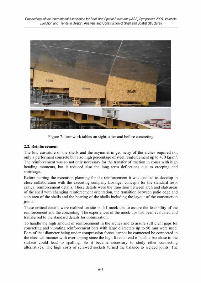
Figure 7: formwork tables on sight; after and before concreting
2.2. Reinforcement The low curvature of the shells and the asymmetric geometry of the arches required not only a performant concrete but also high percentage of steel reinforcement up to 470 kg/m³. The reinforcement was so not only necessary for the transfer of traction in zones with high bending moments, but it reduced also the long term deflections due to creeping and shrinkage. Before starting the execution planning for the reinforcement it was decided to develop in close collaboration with the executing company Losinger concepts for the standard resp. critical reinforcement details. These details were the transition between arch and slab areas of the shell with changing reinforcement orientation, the transition between patio edge and slab area of the shells and the bearing of the shells including the layout of the construction joints. These critical details were realized on site in 1:1 mock ups to assure the feasibility of the reinforcement and the concreting. The experiences of the mock-ups had been evaluated and transferred to the standard details for optimization. To handle the high amount of reinforcement in the arches and to assure sufficient gaps for concreting and vibrating reinforcement bars with large diameters up to 50 mm were used. Bars of that diameter being under compression forces cannot be connected be connected in the classical manner with overlapping since the high force at end of such a bar close to the surface could lead to spalling. So it became necessary to study other connecting alternatives. The high costs of screwed sockets turned the balance to welded joints. The
645

Proceedings of the International Association for Shell and Spatial Structures (IASS) Symposium 2009, Valencia Evolution and Trends in Design, Analysis and Construction of Shell and Spatial Structures
welded joints were finally executed on site with the aid of a perforated socket which was placed around the end of the reinforcement bars and guaranteed the position of the bars during welding.
Figure 8: welded joint of diameter 50 mm bars in socket
The major parts of the shells are despite of the low curvature and the so induced high bending moments in all service loading conditions exposed only to compression. Beside this in ultimate load cases some of these areas are eventually exposed to traction. So it was decided to place a maximum of welding joints, even if they were designed to withstand the same tension forces as the bars itself, into the zones, which are exposed only to compression. This was done to reduce the number of eventual weak points in the structure. Therefore these zones were identified and the layout of the 50 mm reinforcement bars was adapted accordingly.
646

Proceedings of the International Association for Shell and Spatial Structures (IASS) Symposium 2009, Valencia Evolution and Trends in Design, Analysis and Construction of Shell and Spatial Structures
As the 50 mm bars were fixed on both sides of the shells and connected by welding joints, they became sensible to temperature differences on building site. In daytime exposed to the sun they heated up and dilated. This lead to an uplift of the whole reinforcement layers off the formwork by several centimeters. To avoid further problems while pouring the concrete the reinforcement was covered before concreting with soggy fabrics and to cool them that way. As soon as the standard reinforcement concept for the arches was defined the above-named prototype details could be developed. For the transition between arches and slab areas with changing reinforcement orientation mainly the positioning for the lower layers was to define. The upper layers were due to the different concrete thicknesses without conflict. The prototype for this detail served at the same time to test different formwork facings and the concrete composition in regard to the viscosity and the ability for pumping. This was important to assure the concreting of the shells in the required slopes without counter formwork. As the first concrete compositions showed too much sensitivity in regard to the water concentration the further development of the concrete composition was done adding plastic fibers. These fibers improved the behavior of the concrete during the vibration so that the shells could be executed without counter-formwork even in the zones with slopes up to 15%.
Figure 9: 1:1 mock up for transition zone between arches and slab areas during concreting
647

Proceedings of the International Association for Shell and Spatial Structures (IASS) Symposium 2009, Valencia Evolution and Trends in Design, Analysis and Construction of Shell and Spatial Structures
Figure 10: sketches showing the reinforcement concept of the lower layer in the transition zone between arches and slab areas
The second detail resp. prototype examined with the mock-up was the patio edge beam and the transition to the slab areas. As the reinforcement orientation of the patio edge beams was orientated radial and tangential, the principal detail had to handle the full span of transition angles between the edge beam and the slab area reinforcement.
648

Proceedings of the International Association for Shell and Spatial Structures (IASS) Symposium 2009, Valencia Evolution and Trends in Design, Analysis and Construction of Shell and Spatial Structures
Figure 11: 1:1 detail of patio edge beam with transition to slab area
The detail was solved by adding additional radial and tangential reinforcement layers in the slab area so that the full reinforcement sections of slab areas were covered. This solution allowed to working without working without bending of reinforcement bars and could so be adapted to all transition angles.
Figure 12: 1:1 mock-up detail of patio edge beam with transition to slab area
649

Proceedings of the International Association for Shell and Spatial Structures (IASS) Symposium 2009, Valencia Evolution and Trends in Design, Analysis and Construction of Shell and Spatial Structures
Figure 13: extract of a reinforcement drawing of a patio edge beam
The tangential reinforcement of the patio edge beams required further attention. Due to the high level of reinforcement it was partly necessary to connect the reinforcement bars without overlapping. Otherwise the gaps for vibration of concrete weren’t sufficient. The non-circular geometry of the patio edges could only be approached with bars curved with a constant radius. To reduce the number of different bending radiuses it was necessary to provide sufficient connections which could be adapted in length on site. Therefore screwed and welded connections were alternated at the patio edge beams. The achieved solutions for the above mentioned reinforcement details allowed establishing the reinforcement drawings mainly in 2d. Only some supplementary information out of the 3d-model were necessary, as for example the true length of the arches and the patio edge beams.
650

Proceedings of the International Association for Shell and Spatial Structures (IASS) Symposium 2009, Valencia Evolution and Trends in Design, Analysis and Construction of Shell and Spatial Structures
Figure 14: 3d-model of the shell bearing detail including the post-tensioning cables in the slab over the basement
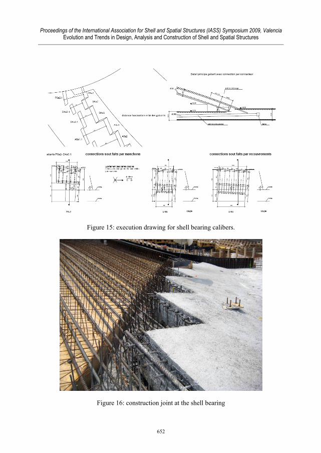
In contrast a full design in 3d was necessary for the third and last prototype detail, the shell bearings. This was necessary to assure a right positioning and orientation of the reinforcement bars corbelling outwards the construction joint between slab over the basement and the shells. As the formwork tables of the shells couldn’t be placed already before concreting the shell bearings, they couldn’t serve as backing for the right orientation. Therefore two calibers were placed on the horizontal formwork of the slab of ground floor, in which the reinforcement bars of the shell bearings were placed. The required geometric data for the calibers, which had each a unique geometry and were generated in a 3d-model, was given to the building site on a 2d-drawing, see figure 15. The given information on these quite unusual drawings was adjusted with the experiences of the prototype and after the execution of the first shell bearings.
651
Proceedings of the International Association for Shell and Spatial Structures (IASS) Symposium 2009, Valencia Evolution and Trends in Design, Analysis and Construction of Shell and Spatial Structures
Figure 15: execution drawing for shell bearing calibers.
Figure 16: construction joint at the shell bearing
652
Proceedings of the International Association for Shell and Spatial Structures (IASS) Symposium 2009, Valencia Evolution and Trends in Design, Analysis and Construction of Shell and Spatial Structures
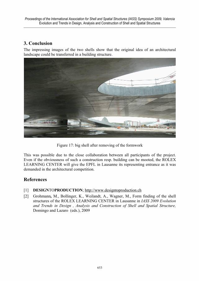
3. Conclusion The impressing images of the two shells show that the original idea of an architectural landscape could be transferred in a building structure.
Figure 17: big shell after removing of the formwork
This was possible due to the close collaboration between all participants of the project. Even if the obviousness of such a construction resp. building can be mooted, the ROLEX LEARNING CENTER will give the EPFL in Lausanne its representing entrance as it was demanded in the architectural competition.
References
[1] DESIGNTOPRODUCTION; http://www.designtoproduction.ch [2] Grohmann, M., Bollinger, K., Weilandt, A., Wagner, M., Form finding of the shell
structures of the ROLEX LEARNING CENTER in Lausanne in IASS 2009 Evolution and Trends in Design , Analysis and Construction of Shell and Spatial Structure, Domingo and Lazaro (eds.), 2009
653
Related Documents