Citation: Maeda, Y. Roles of Sulfites in Reverse Osmosis (RO) Plants and Adverse Effects in RO Operation. Membranes 2022, 12, 170. https:// doi.org/10.3390/membranes12020170 Academic Editor: Bart Van der Bruggen Received: 27 December 2021 Accepted: 21 January 2022 Published: 31 January 2022 Publisher’s Note: MDPI stays neutral with regard to jurisdictional claims in published maps and institutional affil- iations. Copyright: © 2022 by the author. Licensee MDPI, Basel, Switzerland. This article is an open access article distributed under the terms and conditions of the Creative Commons Attribution (CC BY) license (https:// creativecommons.org/licenses/by/ 4.0/). membranes Review Roles of Sulfites in Reverse Osmosis (RO) Plants and Adverse Effects in RO Operation Yasushi Maeda LG Chem Japan Co., Ltd., Kyobashi Trust Tower 12F, 2-1-3 Kyobashi Chuo-ku, Tokyo 104-0031, Japan; [email protected]; Tel.: +81-3-5299-4530 Abstract: More than 60 years have passed since UCLA first announced the development of an innovative asymmetric cellulose acetate reverse osmosis (RO) membrane in 1960. This innovation opened a gate to use RO for commercial use. RO is now ubiquitous in water treatment and has been used for various applications, including seawater desalination, municipal water treatment, wastewater reuse, ultra-pure water (UPW) production, and industrial process waters, etc. RO is a highly integrated system consisting of a series of unit processes: (1) intake system, (2) pretreatment, (3) RO system, (4) post-treatment, and (5) effluent treatment and discharge system. In each step, a variety of chemicals are used. Among those, sulfites (sodium bisulfite and sodium metabisulfite) have played significant roles in RO, such as dechlorination, preservatives, shock treatment, and sanitization, etc. Sulfites especially became necessary as dechlorinating agents because polyamide hollow-fiber and aromatic thin-film composite RO membranes developed in the late 1960s and 1970s were less tolerable with residual chlorine. In this review, key applications of sulfites are explained in detail. Furthermore, as it is reported that sulfites have some adverse effects on RO membranes and processes, such phenomena will be clarified. In particular, the following two are significant concerns using sulfites: RO membrane oxidation catalyzed by heavy metals and a trigger of biofouling. This review sheds light on the mechanism of membrane oxidation and triggering biofouling by sulfites. Some countermeasures are also introduced to alleviate such problems. Keywords: bisulfite; metabisulfite; reverse osmosis; dechlorination; ORP; chloramine; chlorine dioxide; preservative; storage; shock treatment; oxidation; degradation; auto-oxidation; heavy metals; radical; a chelating agent; biofouling; trigger; biocides; AOC; cleaning 1. Introduction Reverse osmosis (RO) is a liquid-phase pressure-driven separation process in which applied transmembrane pressure causes selective movement of solvent against its osmotic pressure difference [1]. RO is now ubiquitous in water treatment and has been used for various applications, including seawater desalination, municipal water treatment, wastewater reuse, ultra-pure water (UPW) production, and industrial process waters, etc. Furthermore, RO is anticipated to contribute to the United Nation’s Sustainable Development Goals (SDGs), especially in Goal 6: Clean Water and Sanitation. Then, in Goal 6.a, the following actions are raised: expand international cooperation and capacity building support to developing countries in water and sanitation-related activities and programs. These include water harvesting, desalination, water efficiency, wastewater treatment, recycling, and reuse technologies [2,3]. Regarding RO membrane development, more than 60 years have passed since UCLA first announced the development of an innovative asymmetric cellulose acetate RO mem- brane in 1960. Furthermore, new generation polyamide hollow fiber RO and thin-film composite (TFC) aromatic polyamide RO membranes were developed one after another in the early 1970s and 1977. As a result of continuous improvements, the TFC RO mem- brane performance has been greatly improved, and it is now widely used for a variety Membranes 2022, 12, 170. https://doi.org/10.3390/membranes12020170 https://www.mdpi.com/journal/membranes

Welcome message from author
This document is posted to help you gain knowledge. Please leave a comment to let me know what you think about it! Share it to your friends and learn new things together.
Transcript
�����������������
Citation: Maeda, Y. Roles of Sulfites
in Reverse Osmosis (RO) Plants and
Adverse Effects in RO Operation.
Membranes 2022, 12, 170. https://
doi.org/10.3390/membranes12020170
Academic Editor: Bart Van der
Bruggen
Received: 27 December 2021
Accepted: 21 January 2022
Published: 31 January 2022
Publisher’s Note: MDPI stays neutral
with regard to jurisdictional claims in
published maps and institutional affil-
iations.
Copyright: © 2022 by the author.
Licensee MDPI, Basel, Switzerland.
This article is an open access article
distributed under the terms and
conditions of the Creative Commons
Attribution (CC BY) license (https://
creativecommons.org/licenses/by/
4.0/).
membranes
Review
Roles of Sulfites in Reverse Osmosis (RO) Plants and AdverseEffects in RO OperationYasushi Maeda
LG Chem Japan Co., Ltd., Kyobashi Trust Tower 12F, 2-1-3 Kyobashi Chuo-ku, Tokyo 104-0031, Japan;[email protected]; Tel.: +81-3-5299-4530
Abstract: More than 60 years have passed since UCLA first announced the development of aninnovative asymmetric cellulose acetate reverse osmosis (RO) membrane in 1960. This innovationopened a gate to use RO for commercial use. RO is now ubiquitous in water treatment and hasbeen used for various applications, including seawater desalination, municipal water treatment,wastewater reuse, ultra-pure water (UPW) production, and industrial process waters, etc. RO is ahighly integrated system consisting of a series of unit processes: (1) intake system, (2) pretreatment,(3) RO system, (4) post-treatment, and (5) effluent treatment and discharge system. In each step, avariety of chemicals are used. Among those, sulfites (sodium bisulfite and sodium metabisulfite)have played significant roles in RO, such as dechlorination, preservatives, shock treatment, andsanitization, etc. Sulfites especially became necessary as dechlorinating agents because polyamidehollow-fiber and aromatic thin-film composite RO membranes developed in the late 1960s and 1970swere less tolerable with residual chlorine. In this review, key applications of sulfites are explained indetail. Furthermore, as it is reported that sulfites have some adverse effects on RO membranes andprocesses, such phenomena will be clarified. In particular, the following two are significant concernsusing sulfites: RO membrane oxidation catalyzed by heavy metals and a trigger of biofouling. Thisreview sheds light on the mechanism of membrane oxidation and triggering biofouling by sulfites.Some countermeasures are also introduced to alleviate such problems.
Keywords: bisulfite; metabisulfite; reverse osmosis; dechlorination; ORP; chloramine; chlorinedioxide; preservative; storage; shock treatment; oxidation; degradation; auto-oxidation; heavy metals;radical; a chelating agent; biofouling; trigger; biocides; AOC; cleaning
1. Introduction
Reverse osmosis (RO) is a liquid-phase pressure-driven separation process in whichapplied transmembrane pressure causes selective movement of solvent against its osmoticpressure difference [1]. RO is now ubiquitous in water treatment and has been used forvarious applications, including seawater desalination, municipal water treatment, wastewaterreuse, ultra-pure water (UPW) production, and industrial process waters, etc. Furthermore,RO is anticipated to contribute to the United Nation’s Sustainable Development Goals(SDGs), especially in Goal 6: Clean Water and Sanitation. Then, in Goal 6.a, the followingactions are raised: expand international cooperation and capacity building support todeveloping countries in water and sanitation-related activities and programs. These includewater harvesting, desalination, water efficiency, wastewater treatment, recycling, and reusetechnologies [2,3].
Regarding RO membrane development, more than 60 years have passed since UCLAfirst announced the development of an innovative asymmetric cellulose acetate RO mem-brane in 1960. Furthermore, new generation polyamide hollow fiber RO and thin-filmcomposite (TFC) aromatic polyamide RO membranes were developed one after anotherin the early 1970s and 1977. As a result of continuous improvements, the TFC RO mem-brane performance has been greatly improved, and it is now widely used for a variety
Membranes 2022, 12, 170. https://doi.org/10.3390/membranes12020170 https://www.mdpi.com/journal/membranes
Membranes 2022, 12, 170 2 of 59
of applications. As for the future membrane desalination technology, three technologieswere raised in National Geographic, April 2010 [4]. These three technologies promisedto reduce the energy requirement of desalination up to 30% are forward osmosis, carbonnanotubes, and biomimetics. Among those, nanoporous membranes, including porousgraphene, carbon nanotubes, and graphene oxide, etc., attracted much attention fromacademic researchers [5]. However, it does not seem easy to produce commercial-baseddefect-free RO membranes with nanoporous materials. A way of overcoming materiallimitations for RO applications is to utilize composite materials comprising nanoporousmaterials within a polymer matrix. The use of thin-film nanocomposite (TFN) membranesfor water purification was first described for BWRO membranes by Jeong et al. [6]. Afterthat, many research works on the TFN membranes have been conducted [7,8].
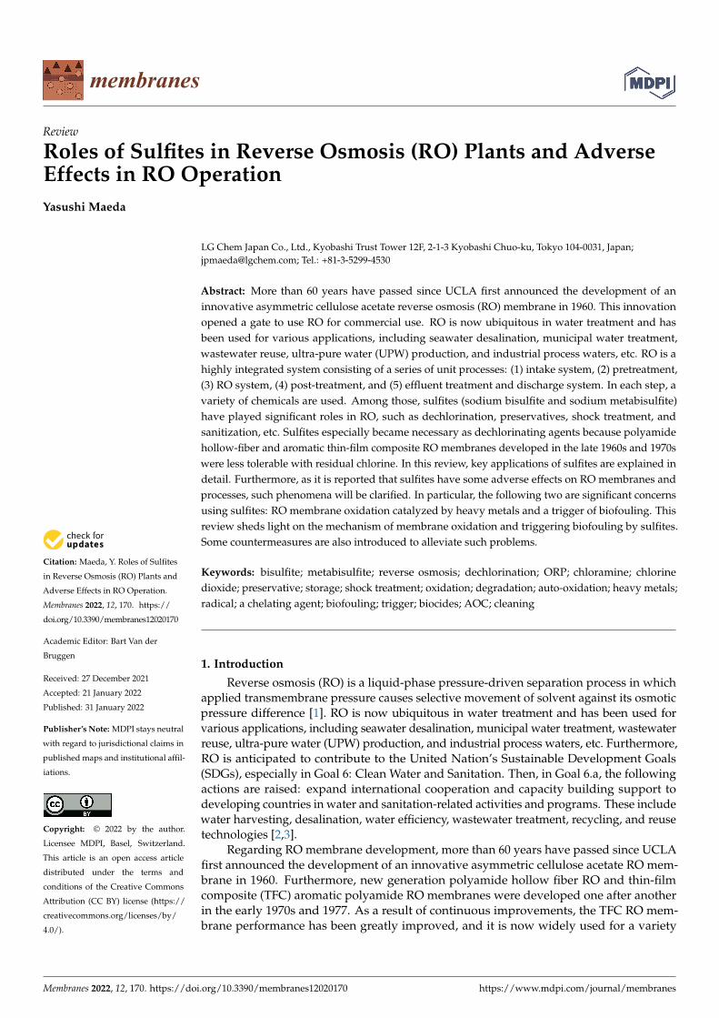
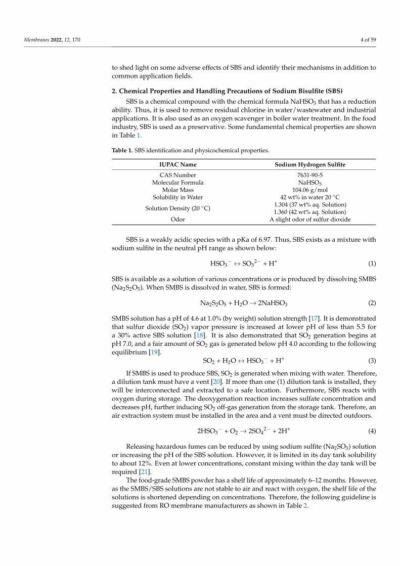
An RO system typically consists of five major unit processes: (1) intake system,(2) pretreatment, (3) RO system, (4) post-treatment, and (5) effluent treatment and dischargesystem, as illustrated in Figure 1. RO membranes and elements are critically importantto separate water from organic and inorganic impurities in the RO system. Several ROmembranes exist, such as aromatic polyamide, and cellulose triacetate, etc., and are fabri-cated into the spiral-wound, hollow fiber, tubular, plate and frame elements. Among them,thin-film composite (TFC) and thin-film nanocomposite (TFN) spiral-wound elements havebeen commonly used in water treatment. However, a series of pretreatment is necessary tosupply feedwaters to RO elements and meet specific requirements for the spiral woundelements, such as silt density index (SDI) < 5 and residual chlorine < 0.1 mg/L, etc.
Membranes 2022, 12, x FOR PEER REVIEW 2 of 60
in the early 1970s and 1977. As a result of continuous improvements, the TFC RO mem-brane performance has been greatly improved, and it is now widely used for a variety of applications. As for the future membrane desalination technology, three technologies were raised in National Geographic, April 2010 [4]. These three technologies promised to reduce the energy requirement of desalination up to 30% are forward osmosis, carbon nanotubes, and biomimetics. Among those, nanoporous membranes, including porous graphene, carbon nanotubes, and graphene oxide, etc., attracted much attention from ac-ademic researchers [5]. However, it does not seem easy to produce commercial-based de-fect-free RO membranes with nanoporous materials. A way of overcoming material limi-tations for RO applications is to utilize composite materials comprising nanoporous ma-terials within a polymer matrix. The use of thin-film nanocomposite (TFN) membranes for water purification was first described for BWRO membranes by Jeong et al. [6]. After that, many research works on the TFN membranes have been conducted [7,8].
An RO system typically consists of five major unit processes: (1) intake system, (2) pretreatment, (3) RO system, (4) post-treatment, and (5) effluent treatment and discharge system, as illustrated in Figure 1. RO membranes and elements are critically important to separate water from organic and inorganic impurities in the RO system. Several RO mem-branes exist, such as aromatic polyamide, and cellulose triacetate, etc., and are fabricated into the spiral-wound, hollow fiber, tubular, plate and frame elements. Among them, thin-film composite (TFC) and thin-film nanocomposite (TFN) spiral-wound elements have been commonly used in water treatment. However, a series of pretreatment is necessary to supply feedwaters to RO elements and meet specific requirements for the spiral wound elements, such as silt density index (SDI) < 5 and residual chlorine < 0.1 mg/L, etc.
Figure 1. Key unit processes of a seawater desalination RO system and chemical usage.
It is observed that a variety of chemicals have to be used in each process steps shown in Figure 1. In the intake system, chlorine is sometimes applied continuously or intermit-tently to protect the intake and pretreatment equipment from bacteria and algae growth. The following chemicals are used in the pretreatment step: coagulants, flocculants, dechlo-rination agents, and antiscalants, etc. When using low-pressure membranes (MF/UF) as the pretreatment, backwash chemicals, such as sodium hypochlorite (NaOCl) and
Figure 1. Key unit processes of a seawater desalination RO system and chemical usage.
It is observed that a variety of chemicals have to be used in each process steps shown inFigure 1. In the intake system, chlorine is sometimes applied continuously or intermittentlyto protect the intake and pretreatment equipment from bacteria and algae growth. Thefollowing chemicals are used in the pretreatment step: coagulants, flocculants, dechlorina-tion agents, and antiscalants, etc. When using low-pressure membranes (MF/UF) as thepretreatment, backwash chemicals, such as sodium hypochlorite (NaOCl) and acid/causticfor chemical-enhanced backwash (CEB), are used. In the RO system, cleaning in place (CIP)chemicals, RO element storage chemicals (preservatives), and biocides are used.
Membranes 2022, 12, 170 3 of 59
However, it should be noted that the use of these chemicals depends strongly on thefeedwater characteristics and operating conditions. For example, some well water treatmentplants are only equipped with cartridge filters with minimal chemical dosage [9–11]. It isreported that the 360 m3/d capacity BWRO plant in Las Palmas, Canary Islands, Spain,has been operating for more than nine years by only dosing 6 mg/L of antiscalant [12].Similarly, Lagartos et al. [13] reported Malta’s Pembroke seawater desalination plant. Theplant can produce 54,000 m3/d of water. The water intake comes from beach wells with asilt density index below 1. The pH is adjusted with sulfuric acid down to 6.7 to protect thepipework and prevent scaling. After pH adjustment, cartridge filters are installed upstreamof the RO unit. It is reported that the cleaning in place (CIP) frequency varies between 6and 10 months, depending on the train condition and time of operation.
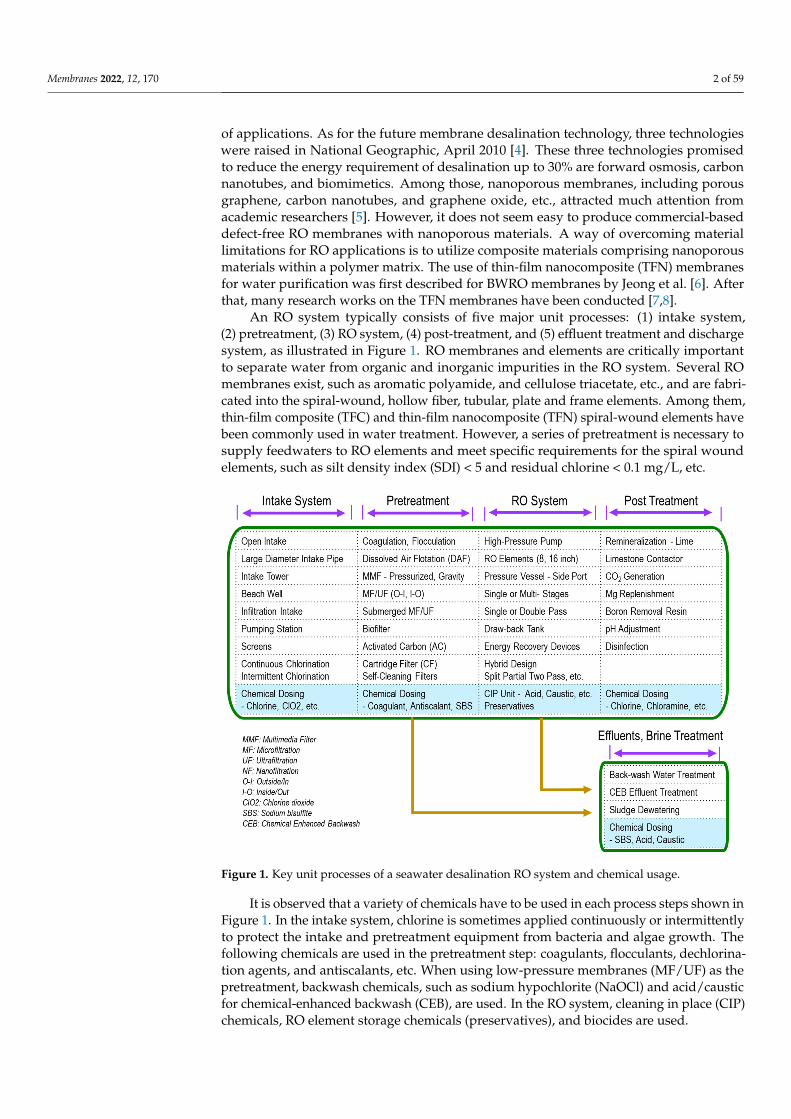
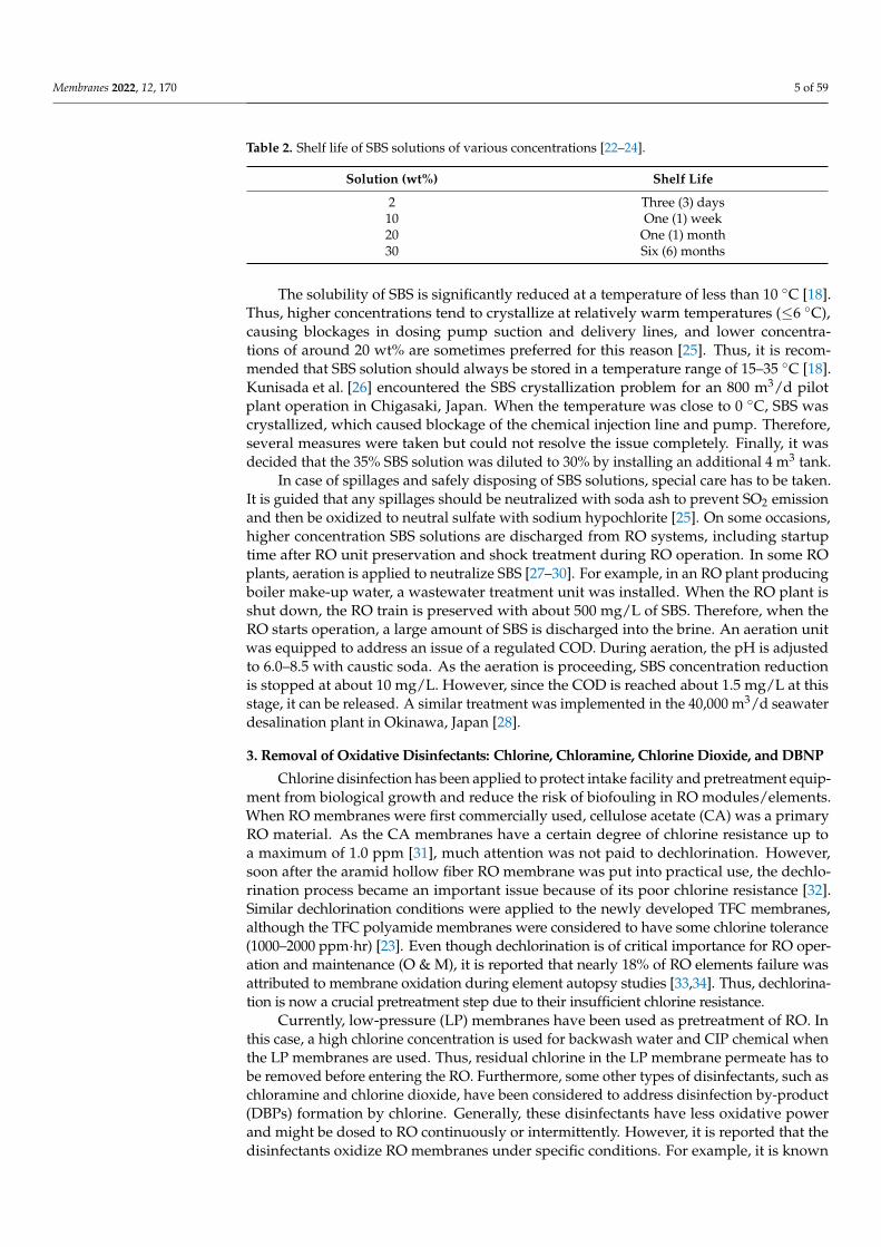
These chemicals might be categorized into the following six (6) items [14]: (1) cleaningagents, (2) dechlorinants, (3) biocides, (4) pH adjustors, (5) coagulants/flocculants, and(6) antiscalants. As for dechlorinants, either sodium metabisulfite (SMBS) or sodiumbisulfite (SBS) is used, and it was estimated as roughly 12–15% of the membrane chemicalsmarket. However, SBS is used for many other applications in the RO unit processes, asshown in Figure 2.
Membranes 2022, 12, x FOR PEER REVIEW 3 of 60
acid/caustic for chemical-enhanced backwash (CEB), are used. In the RO system, cleaning in place (CIP) chemicals, RO element storage chemicals (preservatives), and biocides are used.
However, it should be noted that the use of these chemicals depends strongly on the feedwater characteristics and operating conditions. For example, some well water treat-ment plants are only equipped with cartridge filters with minimal chemical dosage [9–11]. It is reported that the 360 m3/d capacity BWRO plant in Las Palmas, Canary Islands, Spain, has been operating for more than nine years by only dosing 6 mg/L of antiscalant [12]. Similarly, Lagartos et al. [13] reported Malta’s Pembroke seawater desalination plant. The plant can produce 54,000 m3/d of water. The water intake comes from beach wells with a silt density index below 1. The pH is adjusted with sulfuric acid down to 6.7 to protect the pipework and prevent scaling. After pH adjustment, cartridge filters are in-stalled upstream of the RO unit. It is reported that the cleaning in place (CIP) frequency varies between 6 and 10 months, depending on the train condition and time of operation.
These chemicals might be categorized into the following six (6) items [14]: (1) clean-ing agents, (2) dechlorinants, (3) biocides, (4) pH adjustors, (5) coagulants/flocculants, and (6) antiscalants. As for dechlorinants, either sodium metabisulfite (SMBS) or sodium bi-sulfite (SBS) is used, and it was estimated as roughly 12–15% of the membrane chemicals market. However, SBS is used for many other applications in the RO unit processes, as shown in Figure 2.
Figure 2. SMBS/SBS applications for RO systems.
The most critical role of SBS is dechlorination. As the TFC/TFN membranes are less tolerable to chlorine, the residual chlorine must be removed prior to entering the RO unit. The next key application is a use for an RO element preservative for shipping elements and during plant shutdown. Several other SBS applications include deoxygenation, shock treatment as a biostatic agent, and CIP chemical, etc. Thus, SBS can be considered an es-sential chemical for RO processes. However, some adverse effects have been reported. For example, it was reported that under specific conditions, i.e., heavy metals, dissolved oxy-gen, etc. SBS degrades RO membranes [15], or SBS triggers biofouling when overdosing [16].
Figure 2. SMBS/SBS applications for RO systems.
The most critical role of SBS is dechlorination. As the TFC/TFN membranes are lesstolerable to chlorine, the residual chlorine must be removed prior to entering the RO unit.The next key application is a use for an RO element preservative for shipping elementsand during plant shutdown. Several other SBS applications include deoxygenation, shocktreatment as a biostatic agent, and CIP chemical, etc. Thus, SBS can be considered anessential chemical for RO processes. However, some adverse effects have been reported. Forexample, it was reported that under specific conditions, i.e., heavy metals, dissolved oxygen, etc.SBS degrades RO membranes [15], or SBS triggers biofouling when overdosing [16].
In terms of dechlorination and preservative roles, there have been many reports onhow to use SBS and control its dosing amount. However, fewer reports were observed forthe membrane degradation and inducing biofouling. Therefore, this review article aims
Membranes 2022, 12, 170 4 of 59
to shed light on some adverse effects of SBS and identify their mechanisms in addition tocommon application fields.
2. Chemical Properties and Handling Precautions of Sodium Bisulfite (SBS)
SBS is a chemical compound with the chemical formula NaHSO3 that has a reductionability. Thus, it is used to remove residual chlorine in water/wastewater and industrialapplications. It is also used as an oxygen scavenger in boiler water treatment. In the foodindustry, SBS is used as a preservative. Some fundamental chemical properties are shownin Table 1.
Table 1. SBS identification and physicochemical properties.
IUPAC Name Sodium Hydrogen Sulfite
CAS Number 7631-90-5Molecular Formula NaHSO3
Molar Mass 104.06 g/molSolubility in Water 42 wt% in water 20 ◦C
Solution Density (20 ◦C) 1.304 (37 wt% aq. Solution)1.360 (42 wt% aq. Solution)
Odor A slight odor of sulfur dioxide
SBS is a weakly acidic species with a pKa of 6.97. Thus, SBS exists as a mixture withsodium sulfite in the neutral pH range as shown below:
HSO3− ↔ SO3
2− + H+ (1)
SBS is available as a solution of various concentrations or is produced by dissolving SMBS(Na2S2O5). When SMBS is dissolved in water, SBS is formed:
Na2S2O5 + H2O→ 2NaHSO3 (2)
SMBS solution has a pH of 4.6 at 1.0% (by weight) solution strength [17]. It is demonstratedthat sulfur dioxide (SO2) vapor pressure is increased at lower pH of less than 5.5 fora 30% active SBS solution [18]. It is also demonstrated that SO2 generation begins atpH 7.0, and a fair amount of SO2 gas is generated below pH 4.0 according to the followingequilibrium [19].
SO2 + H2O↔ HSO3− + H+ (3)
If SMBS is used to produce SBS, SO2 is generated when mixing with water. Therefore,a dilution tank must have a vent [20]. If more than one (1) dilution tank is installed, theywill be interconnected and extracted to a safe location. Furthermore, SBS reacts withoxygen during storage. The deoxygenation reaction increases sulfate concentration anddecreases pH, further inducing SO2 off-gas generation from the storage tank. Therefore, anair extraction system must be installed in the area and a vent must be directed outdoors.
2HSO3− + O2 → 2SO4
2− + 2H+ (4)
Releasing hazardous fumes can be reduced by using sodium sulfite (Na2SO3) solutionor increasing the pH of the SBS solution. However, it is limited in its day tank solubilityto about 12%. Even at lower concentrations, constant mixing within the day tank will berequired [21].
The food-grade SMBS powder has a shelf life of approximately 6–12 months. However,as the SMBS/SBS solutions are not stable to air and react with oxygen, the shelf life of thesolutions is shortened depending on concentrations. Therefore, the following guideline issuggested from RO membrane manufacturers as shown in Table 2.
Membranes 2022, 12, 170 5 of 59
Table 2. Shelf life of SBS solutions of various concentrations [22–24].
Solution (wt%) Shelf Life
2 Three (3) days10 One (1) week20 One (1) month30 Six (6) months
The solubility of SBS is significantly reduced at a temperature of less than 10 ◦C [18].Thus, higher concentrations tend to crystallize at relatively warm temperatures (≤6 ◦C),causing blockages in dosing pump suction and delivery lines, and lower concentra-tions of around 20 wt% are sometimes preferred for this reason [25]. Thus, it is recom-mended that SBS solution should always be stored in a temperature range of 15–35 ◦C [18].Kunisada et al. [26] encountered the SBS crystallization problem for an 800 m3/d pilotplant operation in Chigasaki, Japan. When the temperature was close to 0 ◦C, SBS wascrystallized, which caused blockage of the chemical injection line and pump. Therefore,several measures were taken but could not resolve the issue completely. Finally, it wasdecided that the 35% SBS solution was diluted to 30% by installing an additional 4 m3 tank.
In case of spillages and safely disposing of SBS solutions, special care has to be taken.It is guided that any spillages should be neutralized with soda ash to prevent SO2 emissionand then be oxidized to neutral sulfate with sodium hypochlorite [25]. On some occasions,higher concentration SBS solutions are discharged from RO systems, including startuptime after RO unit preservation and shock treatment during RO operation. In some ROplants, aeration is applied to neutralize SBS [27–30]. For example, in an RO plant producingboiler make-up water, a wastewater treatment unit was installed. When the RO plant isshut down, the RO train is preserved with about 500 mg/L of SBS. Therefore, when theRO starts operation, a large amount of SBS is discharged into the brine. An aeration unitwas equipped to address an issue of a regulated COD. During aeration, the pH is adjustedto 6.0–8.5 with caustic soda. As the aeration is proceeding, SBS concentration reductionis stopped at about 10 mg/L. However, since the COD is reached about 1.5 mg/L at thisstage, it can be released. A similar treatment was implemented in the 40,000 m3/d seawaterdesalination plant in Okinawa, Japan [28].
3. Removal of Oxidative Disinfectants: Chlorine, Chloramine, Chlorine Dioxide, and DBNP
Chlorine disinfection has been applied to protect intake facility and pretreatment equip-ment from biological growth and reduce the risk of biofouling in RO modules/elements.When RO membranes were first commercially used, cellulose acetate (CA) was a primaryRO material. As the CA membranes have a certain degree of chlorine resistance up toa maximum of 1.0 ppm [31], much attention was not paid to dechlorination. However,soon after the aramid hollow fiber RO membrane was put into practical use, the dechlo-rination process became an important issue because of its poor chlorine resistance [32].Similar dechlorination conditions were applied to the newly developed TFC membranes,although the TFC polyamide membranes were considered to have some chlorine tolerance(1000–2000 ppm·hr) [23]. Even though dechlorination is of critical importance for RO oper-ation and maintenance (O & M), it is reported that nearly 18% of RO elements failure wasattributed to membrane oxidation during element autopsy studies [33,34]. Thus, dechlorina-tion is now a crucial pretreatment step due to their insufficient chlorine resistance.
Currently, low-pressure (LP) membranes have been used as pretreatment of RO. Inthis case, a high chlorine concentration is used for backwash water and CIP chemical whenthe LP membranes are used. Thus, residual chlorine in the LP membrane permeate has tobe removed before entering the RO. Furthermore, some other types of disinfectants, such aschloramine and chlorine dioxide, have been considered to address disinfection by-product(DBPs) formation by chlorine. Generally, these disinfectants have less oxidative powerand might be dosed to RO continuously or intermittently. However, it is reported that thedisinfectants oxidize RO membranes under specific conditions. For example, it is known
Membranes 2022, 12, 170 6 of 59
that chloramine is converted to bromamine in seawater and that bromamine causes ROmembrane oxidation [35]. Thus, when chloramine and chlorine dioxide are used in the ROprocess, those oxidants may need to be removed.
As mentioned, several types of oxidants are used in pretreatment, CIP, and disinfection,etc. In addition to preventing RO membrane oxidation, the residual oxidants must beremoved prior to discharge to protect the watershed environment. In this section, oxidativechemical removal technologies with sulfites will be discussed.
3.1. Dechlorination
Dechlorination has been achieved by an activated carbon (AC) bed or sulfite chemicalsin RO processes. However, carbon filtration is typically not recommended for dechlorina-tion of RO feed water unless the concentrations of organics are high enough to warrantits use and other circumstances prohibit the use of sulfites [24,36]. Usage of AC filtershas the following concerns in RO O&M: aiding the growth of microbes and sloughing offcarbon fines. Thus, sulfite compounds, sodium sulfite (Na2SO3), SBS (NaHSO3), and SMBS(Na2S2O5) are used for dechlorination. These sulfites react with chlorine as follows:
Sodium sulfite: Na2SO3 + Cl2 + H2O→ Na2SO4 + 2HCl (5)
Sodium bisulfite (SBS): NaHSO3 + Cl2 + H2O→ NaHSO4 + 2HCl (6)
Sodium metabisulfite (SMBS): Na2S2O5 + 2Cl2 + 3H2O→ 2NaHSO4 + 4HCl (7)
Based on these reactions, theoretical dosages for different sulfites are summarized inTable 3.
Table 3. Theoretical sulfites dosages for dechlorination [21,37].
Sulfites Molecular Weight Theoretical Dosage to Remove 1 mg Chlorine (mg)
Sodium sulfite 126.1 1.78Sodium bisulfite (SBS) 104.1 1.46
Sodium metabisulfite (SMBS) 190.2 1.34
SBS and SMBS have been commonly utilized in RO dechlorination among thosesulfites. When using SMBS, non-cobalt catalyzed and food-grade quality SMBS should beused. It is reported that cobalt-catalyzed SBS for dechlorination resulted in the degradationof polyamide membranes [31]. Regarding the necessary dosing amount in the field, astoichiometric dosage of SBS was insufficient for complete dechlorination. Thus, an excessof the stoichiometric dosage (mg dechlorination agent/mg Cl2) is needed. However, itwas unclear how much extra dosing should be applied to actual plants. A few researchworks were conducted by focusing on this issue and measuring the reaction kinetics ofvarious reducing agents under different stoichiometric dosing rates [38–40]. The findingssuggest that the three stoichiometric dosage of SBS was successful in achieving completedechlorination. It was also found that organic and inorganic matter may be responsiblefor inhibiting dechlorination at low stoichiometric dosages of SBS [39]. Apart from theseexperimental results, 10% excess dechlorinating chemicals are suggested for common waterand wastewater treatment [37]. However, in the case of RO application, a higher amountof sulfites dosage has been recommended due to a concern about membrane oxidationand stability of sulfites during storage. Almost all RO-related books and manufacturers’technical bulletins state an appropriate amount of SBS dosing for dechlorination. Thesuggested dosing amount so far is summarized in Table 4.
Membranes 2022, 12, 170 7 of 59
Table 4. The suggested dosing amount of sulfites compounds for dechlorination.
Sulfites Dosage to Remove 1 mg Chlorine (mg) Stochiometric Amount Ratio Comments Reference
SMBS
3>3
2.24>2.24
Brackish waterSeawater [23]
3 2.24 [41,42]2 1.49 [24]
SBS3–5 Aramid polyamide [43]>2 [44]
2 1.37 [45]
Typically, 2–3 mg of SMBS are suggested to remove 1 mg of chlorine. Using three tofive times the stoichiometric amount of SBS was suggested for the aramid hollow fiberRO [43]. In Table 4, the stoichiometric amount ratio (dosing amount/stoichiometric amount)is also listed. When determining the actual dosage, the stoichiometric amount ratio mightbe considered a safety factor [36]. The following safety factors are generally applied:1.2–2.0 [46] and 1.5–2.0 [36]. One technical bulletin mentioned that more SMBS might berequired for seawater when dissolved oxygen is present [23]. This suggestion may havereferred to an uncommon event in the Middle East. The Umm Lujj 2 Desalination Plantis located on the Red Sea Coast 154 km north of Yanbu. The Umm Lujj 2 was designed toproduce 4400 m3 per day of drinking water and started in 1986. A 28-day trial using 0.5 ppmchlorination and dechlorination accompanying 5 ppm SBS was unsuccessful [47]. Evenwith adopting a higher safety factor of 6.8, damage to chlorine-sensitive membranes wasfound, and this degradation resulted in premature failure of membrane modules [48]. Amembrane autopsy revealed that the membrane was attacked by halogen compounds [49].Osta et al. [47] attributed this phenomenon to a fast reaction with oxygen as one of thereasons due to: (a) metals in seawater serving as catalysts, (b) high ionic strength, (c) specificpH, (d) high bicarbonate concentration, and (e) high temperature. As for heavy metals,the raw seawater of the Red Sea was analyzed along with troubleshooting efforts for CTAmembrane oxidation in the Jeddah Phase I plant [50]. A higher copper ion concentration of1.8 ppb was detected than the standard concentration of less than 0.2 ppb. Therefore, specialattention should be paid when expecting a higher level of heavy metals from raw seawaterand coagulants (impurities). In this case, residual chlorine may attack RO membranes rapidly.
Thus far, the safety-dosing amount of SBS/SMBS for preventing RO membrane oxi-dation was discussed. However, as mentioned in Section 8, overdoing sulfites may haveadverse effects, e.g., membrane oxidation, biofouling, etc. [51]. Thus, the residual SBSconcentration should be carefully controlled. In addition, it is said that the over-injectionof sulfite causes an increased breakdown of dissolved oxygen in the water. This kind ofenvironmental stress increases the potential for a heavy growth of slime-forming species ofbacteria, which can quickly foul an RO system. Byrne [52] pointed out that this potentialcan be minimized by maintaining a residual sulfite concentration greater than zero but lessthan 2 mg/L as SBS.
3.2. Dechlorination Point Considerations
The rate of dechlorination is rapid in laboratory experiments. At three times thestoichiometric amount of SBS/SMBS, dechlorination time reaching 0.02 mg/L of residualchlorine is 37 s for 1 mg/L of initial chlorine concentration [38]. Other reference articlesreported a similar completion time of 15–20 s [20,37]. Thus, it is expected that an excess ofthe stoichiometric dosage of sulfites could achieve complete dechlorination within less than1 min [53]. The dechlorination reaction requires mixing to ensure completion. Therefore,proper in-line mixing is needed, which preferably includes a static mixer [20]. When SBS isdosed after cartridge filters (CFs), the SMBS solution should be filtered through a separatecartridge before being injected into the RO feed [41].
Membranes 2022, 12, 170 8 of 59
The next issue is where SBS should be injected either before or after a CF. Until the1980s, it was recommended that SMBS is injected prior to the CFs [22,23]. However, inthe 1990s, membrane manufacturers began suggesting that the SBS injection point is setafter the CF [43,54]. One RO manufacturer recognized that the optimum injection pointof SBS is at the suction of a high-pressure pump and started recommending the new SBSinjection point location for existing RO plants as well as for new projects [43]. It was saidthat this dechlorination injection point location would minimize or eliminate biologicalfouling in all piping before the high-pressure pump suction. However, to implement thistechnology, a potential difficulty assuring no chlorine entrance to the RO modules wasaddressed, as redox meters have a response time of 45 to 60 s. The hold-up time for thefeed between the SBS addition and the RO modules is less than this value. Thus, there isa risk that some residual chlorine could enter the RO modules before the alarm is given.However, few system failures were reported for the aramid hollow fiber RO. Such practicewas implemented in some plants, such as the Dhekelia SWRO plant in Cyprus [55].
Shifting the SBS injection point after the CFs certainly positively affects suppressingdifferential pressure increase of the CFs and reducing filter exchange frequency [56]. How-ever, in terms of suppressing the RO membrane biofouling, its effectiveness is not apparent.Saeed [57,58] reported contradictory results. In the test conducted at the Ar-Birk SWROplant, bacterial generation (doubling) time was used to evaluate biofouling potential. Thegeneration time was higher (lower multiplication capacity) when the SBS dosing point wasbefore the CF. On the other hand, the generation time was decreased significantly, reflectinghigher multiplication capacity and higher biofouling potential when the SBS dosing pointwas moved to after the CF. This observation means that the closer the SBS dosing pointlocation to the RO membranes, the greater the biofouling potential and biofilm formation.This correlated well with operational data of doubling membrane-cleaning frequency whenthe SBS dosing point shifted to after the CF [57]. However, it should be noted that thechlorine concentration used to disinfect the feed to the Al-Birk plant was 4 ppm at theintake and 1–1.2 ppm after the filters. The residual chlorine was removed by dosing anaverage of 6 ppm of SBS, much higher than the stoichiometric amount [59]. Thus, the effectof excessively added SBS may have to be considered when interpreting the results.
As observed in the Al-Birk test, it seems challenging to solve the problem alone bychanging the injection point. Such cases have been reported in several plants. For example,the Gabès 22,500 m3/d BWRO plant in Tunisia was installed in June 1995. The pretreatedwater was initially dechlorinated using SBS before the cartridge filter preceding each high-pressure pump. Soon after the plant startup, severe biological fouling occurred in theRO units. Change of the point of injection of SBS upstream to the downstream of the CFallowed eliminating the problem only in the filter and stabilizing the pressure drop throughthe filter. Such a biofouling problem has continued until the chlorination procedure waschanged to intermittent chlorination/dechlorination method [60].
A similar phenomenon was also observed in the Arcadia Water Treatment Plant inSanta Monica, California. The BWRO plant treats local groundwater to provide up to38,000 m3/d of treated water as part of the City of Santa Monica’s drinking water supply.The original plant configuration included dosing of SBS immediately upstream of the CFsto quench any residual chlorine from the upstream greensand filters. Following the identifi-cation of biological growth in the CFs, plant staff reconfigured the SBS dosing downstreamof the CFs, allowing chlorine residual to disinfect the CFs effectively. However, whilethe biofouling was arrested at that location, it spread to the downstream RO membranesthemselves [61]. Therefore, in this plant, chloramine addition was implemented to tacklethe biofouling. It was reported that this new disinfection protocol resulted in a significantreduction in biofouling.
The following example is the seawater desalination plant with an 18,000 m3/d capacityin Santa Barbara, Curacao [62]. Chlorine is dosed in the beach clear well. SBS is injectedafter a CF when shock pre-chlorine is performed. After an initial lag period, the differentialpressure (DP) increase becomes more rapid. During the first 15 months, the plant had to
Membranes 2022, 12, 170 9 of 59
conduct CIP five times. The autopsy data demonstrates that this DP increase is due tobiological growth on the membrane. To reduce the rate of biofilm growth, a program ofweekly, overnight biocide soaks with a commercial non-oxidative biocide was implemented.The result was a significant reduction in the rate of DP increase. A subsequent attemptwas to control SBS dosing. In the original design for the Santa Barbara plant, SBS dosingwas based on the free chlorine level anticipated during the regular shock chlorination.This practice ensures that no chlorine reaches the membrane; however, it also results in anexcessive SBS residual in the feed. Then, the SBS addition program was modified to reducethe SBS excess. After the cleaning was performed, the rate of DP increase was immediatelyand positively affected by the change in SBS addition.
As observed in the case studies above, it was found that shifting the SBS injection pointalone does not ensure a biofouling-free operation, even though this practice has a positiveeffect on reducing the DP increase rate in the CF. Thus, other measures have to be consideredto control biofouling. These include intermittent chlorination, chloramine/chlorine dioxidedisinfection, and minimizing SBS dosing amount, etc.
3.3. Monitoring Dechlorination
Dechlorination has been monitored by either a chlorine analyzer or an oxidation-reduction potential (ORP) meter [20,22,41]. In addition, measuring residual SBS concentra-tion is helpful to avoid overdosing. It seems that DuPont first considered applying the ORPfor monitoring residual chlorine to RO systems. Their study indicated that ORP could beuseful in an indication of the level of reduction of oxidant (chlorine) used for disinfectionin seawater [63]. However, at that time, the ORP technology was not mature enough, andreadings demonstrated extreme excursions. After that, along with technological improve-ments and actual plant data accumulation, it became common to equip with an ORP meteralone or together with a chlorine meter in seawater desalination. In a particular case, it wasreported that two ORP meters and one chlorine meter were installed to ensure chlorineremoval in the Shuqaiq desalination plant [64,65].
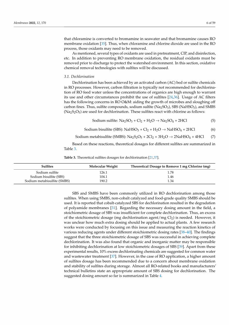
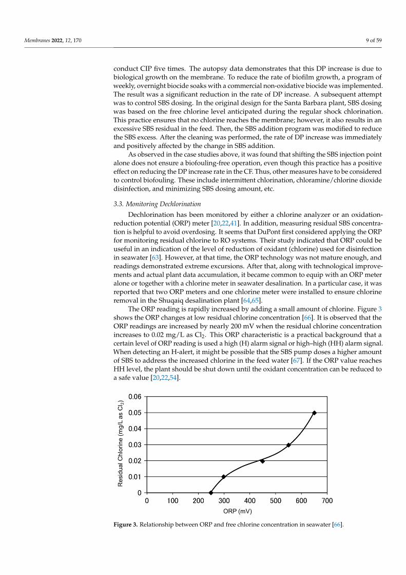
The ORP reading is rapidly increased by adding a small amount of chlorine. Figure 3shows the ORP changes at low residual chlorine concentration [66]. It is observed that theORP readings are increased by nearly 200 mV when the residual chlorine concentrationincreases to 0.02 mg/L as Cl2. This ORP characteristic is a practical background that acertain level of ORP reading is used a high (H) alarm signal or high–high (HH) alarm signal.When detecting an H-alert, it might be possible that the SBS pump doses a higher amountof SBS to address the increased chlorine in the feed water [67]. If the ORP value reachesHH level, the plant should be shut down until the oxidant concentration can be reduced toa safe value [20,22,54].
Membranes 2022, 12, x FOR PEER REVIEW 10 of 60
Table 5. The reported threshold ORP values to avoid membrane oxidation.
Membrane Manufacturer High Alarm H (mV)
High-High Alarm HH (mV)
Reference
A - 175–200 [68] B 300 350 [69] C 250 300 [70]
D 270 (at pH = 6.0)
[71] 200 (at pH = 8.0)
Figure 3. Relationship between ORP and free chlorine concentration in seawater [66].
A slight difference in H and HH values can be observed. One manufacturer proposes the pH-dependent H and HH values, as the ORP reading depends on feed pH. Thus, one may need to consider adding or reducing 50 mV for every one (1) change in pH [66]. Alt-hough the listed H and HH values are not limited to specific water types, it might be natural to consider that they are mainly applicable to surface seawater, as the pretreated seawater conditions are not significantly varied. For example, in the Okinawa SWRO plant, the 250 mV of ORP was set as the HH alarm [28].
It is known that the ORP value depends on various factors, such as water sources (groundwater, surface water, TDS, ions, etc.), pH, dissolved oxygen, temperature, and the organics present in the water [46,72]. In addition, it is pointed out that the absolute reading of the ORP meter may fluctuate due to factors, such as electrode contamination, due to continuous use and fluctuations in the manufacturing factors of the ORP electrode itself [73]. These characteristics mean that the ORP value completing the chlorine removal var-ies with feed water types and physicochemical conditions, as schematically shown in Fig-ure 4.
Figure 3. Relationship between ORP and free chlorine concentration in seawater [66].
Membranes 2022, 12, 170 10 of 59
In terms of the H and HH alarm levels, several readings have been proposed bymembrane suppliers and experts in this area. Table 5 summarizes the proposed H and HHthreshold ORP value.
Table 5. The reported threshold ORP values to avoid membrane oxidation.
MembraneManufacturer
High AlarmH (mV)
High-High AlarmHH (mV) Reference
A - 175–200 [68]B 300 350 [69]C 250 300 [70]
D270 (at pH = 6.0)
[71]200 (at pH = 8.0)
A slight difference in H and HH values can be observed. One manufacturer proposesthe pH-dependent H and HH values, as the ORP reading depends on feed pH. Thus,one may need to consider adding or reducing 50 mV for every one (1) change in pH [66].Although the listed H and HH values are not limited to specific water types, it might benatural to consider that they are mainly applicable to surface seawater, as the pretreatedseawater conditions are not significantly varied. For example, in the Okinawa SWRO plant,the 250 mV of ORP was set as the HH alarm [28].
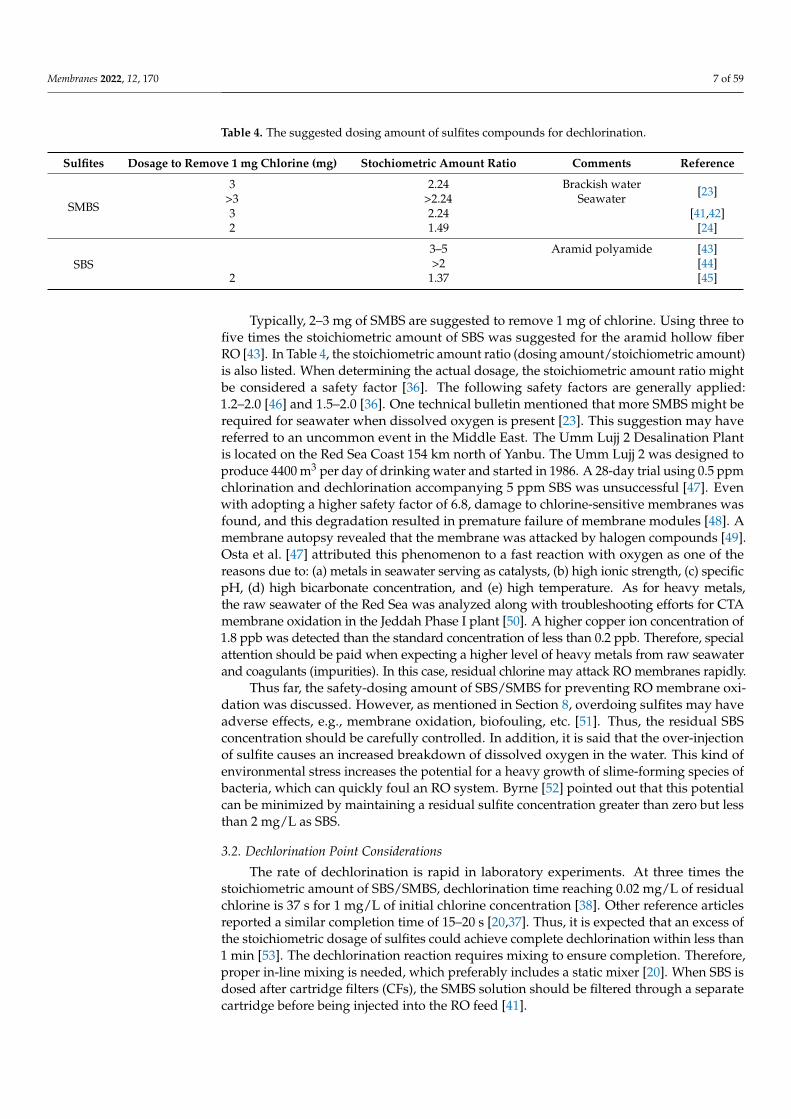
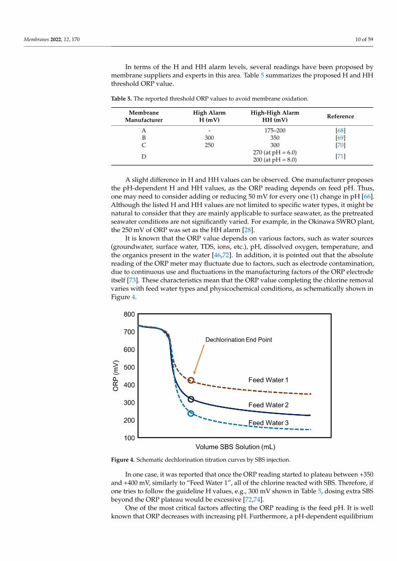
It is known that the ORP value depends on various factors, such as water sources(groundwater, surface water, TDS, ions, etc.), pH, dissolved oxygen, temperature, andthe organics present in the water [46,72]. In addition, it is pointed out that the absolutereading of the ORP meter may fluctuate due to factors, such as electrode contamination,due to continuous use and fluctuations in the manufacturing factors of the ORP electrodeitself [73]. These characteristics mean that the ORP value completing the chlorine removalvaries with feed water types and physicochemical conditions, as schematically shown inFigure 4.
Membranes 2022, 12, x FOR PEER REVIEW 11 of 60
Figure 4. Schematic dechlorination titration curves by SBS injection.
In one case, it was reported that once the ORP reading started to plateau between +350 and +400 mV, similarly to “Feed Water 1”, all of the chlorine reacted with SBS. There-fore, if one tries to follow the guideline H values, e.g., 300 mV shown in Table 5, dosing extra SBS beyond the ORP plateau would be excessive [72,74].
One of the most critical factors affecting the ORP reading is the feed pH. It is well known that ORP decreases with increasing pH. Furthermore, a pH-dependent equilib-rium between hypochlorous acid (HOCl) and hypochlorite ion (OCl−) affects the ORP changes. At pH = 6.0, HOCl is dominant, and at pH = 9.0, OCl− is a dominant species. These two have the standard electrode potentials of 1.48 V and 0.81 V, respectively.
HOCl + H+ + 2e− → Cl− + H2O (8)
ClO− + H2O + 2e− → Cl− + 2OH− (9)
The reported dechlorinated water ORP at pH = 10.0, where the second-pass feed pH was increased to improve boron rejection, showed about 30–40 mV [15]. Byrne [75] sounded the following alarm related to the ORP fluctuations with pH. When ORP is used to control SBS dosage, the results may be disastrous if the RO permeate returns to an up-stream feed tank when process water is not demanded. During times of minimal usage, the ratio of RO permeate in the blended feed is increased. Added SBS will have an in-creased impact on the water pH and cause it to drop. The declining pH will cause the ORP reading to increase even if no chlorine is present. The control system will respond by add-ing even more SBS, and the SBS injection pump will eventually max out on its dosage.
The next unclear point about the ORP measurements is the effect of salinity or total dissolved solids (TDS). There is a lack of knowledge on how salinity might influence ORP during chlorination/dechlorination. Xie et al. [76] titrated chlorinated water (using sodium hypochlorite, NaOCl) with SMBS. The ORP was monitored for waters of different salini-ties prepared by diluting seawater (TDS, 33,800 mg/L, pH 8.2, Singapore) with deionized water (TDS, 50 mg/L). The most critical parameter for RO dechlorination might be the endpoint ORP. From their results, the following two key findings can be drawn. First, before adding the titratant, the raw water had ORP values that varied from 270 mV for deionized water to 54 mV for seawater. Similarly, when injecting the same amount of NaOCl, the seawater sample demonstrated the lowest ORP value. The endpoint ORP dif-ference between seawater and 25% seawater was nearly 150 mV. Second, the endpoint ORP value was increased by increasing the initial NaOCl dosing amount. It is reported
Figure 4. Schematic dechlorination titration curves by SBS injection.
In one case, it was reported that once the ORP reading started to plateau between +350and +400 mV, similarly to “Feed Water 1”, all of the chlorine reacted with SBS. Therefore, ifone tries to follow the guideline H values, e.g., 300 mV shown in Table 5, dosing extra SBSbeyond the ORP plateau would be excessive [72,74].
One of the most critical factors affecting the ORP reading is the feed pH. It is wellknown that ORP decreases with increasing pH. Furthermore, a pH-dependent equilibrium
Membranes 2022, 12, 170 11 of 59
between hypochlorous acid (HOCl) and hypochlorite ion (OCl−) affects the ORP changes.At pH = 6.0, HOCl is dominant, and at pH = 9.0, OCl− is a dominant species. These twohave the standard electrode potentials of 1.48 V and 0.81 V, respectively.
HOCl + H+ + 2e− → Cl− + H2O (8)
ClO− + H2O + 2e− → Cl− + 2OH− (9)
The reported dechlorinated water ORP at pH = 10.0, where the second-pass feed pHwas increased to improve boron rejection, showed about 30–40 mV [15]. Byrne [75] soundedthe following alarm related to the ORP fluctuations with pH. When ORP is used to controlSBS dosage, the results may be disastrous if the RO permeate returns to an upstream feedtank when process water is not demanded. During times of minimal usage, the ratio of ROpermeate in the blended feed is increased. Added SBS will have an increased impact on thewater pH and cause it to drop. The declining pH will cause the ORP reading to increaseeven if no chlorine is present. The control system will respond by adding even more SBS,and the SBS injection pump will eventually max out on its dosage.
The next unclear point about the ORP measurements is the effect of salinity or totaldissolved solids (TDS). There is a lack of knowledge on how salinity might influence ORPduring chlorination/dechlorination. Xie et al. [76] titrated chlorinated water (using sodiumhypochlorite, NaOCl) with SMBS. The ORP was monitored for waters of different salinitiesprepared by diluting seawater (TDS, 33,800 mg/L, pH 8.2, Singapore) with deionizedwater (TDS, 50 mg/L). The most critical parameter for RO dechlorination might be theendpoint ORP. From their results, the following two key findings can be drawn. First,before adding the titratant, the raw water had ORP values that varied from 270 mV fordeionized water to 54 mV for seawater. Similarly, when injecting the same amount ofNaOCl, the seawater sample demonstrated the lowest ORP value. The endpoint ORPdifference between seawater and 25% seawater was nearly 150 mV. Second, the endpointORP value was increased by increasing the initial NaOCl dosing amount. It is reportedthat the endpoint ORP is increased from 75 mV to 250 mV by increasing the initial chlorinedosage from 1 to 5 mg/L NaOCl in seawater.
Based on these reported data, it is crucial to experimentally determine ORP set points(H and HH) in each plant for controlling or monitoring the residual chlorine. Tate [77]mentioned that ORP setpoints would vary from site to site, thus an experienced technicianshould run titration tests to determine the optimal setpoint. For instance, ORP is set 30 to50 mV lower than that at which 0 ppm free chlorine is achieved. In addition, it is criticalto measure the residual chlorine by a chlorine meter as needed. Lindgren and Casey [78]suggested calibrating the ORP sensors to measure free chlorine residual values, ensuringthat the TFC membranes do not see free chlorine. A portable test kit is used once per weekto measure the free chlorine residual to verify the ORP monitor is functioning properly.This kind of practice is crucial to avoid any abnormal ORP events and membrane oxidation.For example, in the Tampa Bay desalination plant, unusually high ORP values withinthe feed to the RO trains with no free chlorine concentration were detected, resulting inoverdosing SBS (20 ppm) [79].
Up to this point, monitoring ORP and measuring free chlorine methods are discussedto ensure the chlorine-free feed supply to RO. However, as observed in Figure 4, the ORPreading is relatively insensitive to excessive SBS concentration. Thus, RO plants tend tooverdose on SBS. It is indicated [70] that the excess amounts of SBS may lead to rapidmembrane oxidation from catalytic reactions when the feed water contains transition metals(e.g., Co, Cu, Mn, etc.) or membranes are fouled with the transition metals. In addition, theexcess amount of SBS may lead to biofouling from the growth of sulfate-reducing bacteria,severely deteriorating the membrane performance. Thus, the RO membrane supplierrecommends keeping the residual SBS in the feed water below 1 mg/L [70]. Byrne [52]mentions that the biofouling potential can be minimized by maintaining a residual sulfite
Membranes 2022, 12, 170 12 of 59
concentration greater than zero but less than 2 mg/L as SBS. Therefore, it is imperative tomeasure the residual SBS concentration to conform to these targets.
Two sulfite analysis methods are indicated in the standard methods (4500-SO32− SUL-
FITE): the iodometric method and phenanthroline method [80]. The iodometric titrationmethod is suitable for relatively clean waters with concentrations above 2 mg SO3
2−/L.However, following the evolution of sulfite from the sample matrix as SO2, the phenanthrolinecolorimetric determination is preferred for low sulfite levels. In this method, an acidifiedsample is purged with nitrogen gas, and the liberated SO2 is trapped in an absorbing solutioncontaining ferric ion and 1,10-phenanthroline. Ferric iron is reduced to the ferrous state bySO2, producing the orange tris(1,10-phenanthroline) iron (II) complex. After excess ferriciron is removed with ammonium bifluoride, the phenanthroline complex is measured col-orimetrically at 510 nm. In addition, as the RO industry is familiar with chlorine analysis bycolorimetry and ORP, the back-titration with chlorine might be an option.
3.4. Precautions for Integrated Membrane System (IMS)
Various types of hybrid membrane processes have been applied to water and wastew-ater treatment. The hybrid membrane process is the combination of a conventional unitoperation, such as distillation, evaporation, or electrodialysis (ED), with a membrane pro-cess, such as RO [81–83]. The low-pressure (LP) membrane and NF/RO combination haveplayed important roles in municipal water, wastewater treatment, and seawater desalina-tion. In the late 1990s, AWWARF and USEPA funded the project “Integrated multi-objectivemembrane systems for control of microbial and DBP precursors” [84]. Originally, theconcept, referred to as the integrated membrane systems (IMS), covered a wider processarea: (advanced) pretreatment processes combined with NF or RO. However, the IMS wasnarrowed down later to a combination process of LP membrane and NF/RO [85].
LP membranes, including microfiltration (MF) and ultrafiltration (UF), have beenwidely used as pretreatment to RO. In the LP membrane process, chlorine, usually sodiumhypochlorite (NaOCl) solution, is used for cleaning steps in addition to other chemicals. Thefollowing three cleaning methods using NaOCl are commonly utilized and summarized byGilabert-Oriol et al. [86].
• Backwash: Backwash conducts to clean the fibers and, consequently, reduce thetransmembrane pressure (TMP) accumulated during filtration. NaOCl has been themost widely used, and its typical range is 3–20 mg/L with a median of 10 mg/L [87].
• Chemical-enhanced backwash (CEB): the CEB occurs once or twice per day, is charac-terized by taking longer than the backwash, and is conducted by the use of chemicals.For example, NaOCl concentration is at 20–500 mg/L with a median of 150 mg/L.
• Cleaning in place (CIP): CIP occurs once every couple of months and is characterizedby its longer duration (a few hours typically) and higher chemical concentrations usedcompared with CEB. NaOCl is used at elevated concentrations (up to 4000 mg/L withPVDF fibers) for oxidative cleaning.
Thus, it is crucial that residual chlorine does not reach the RO system when using theLP membranes as pretreatment. Busch et al. [88] mentioned that a few erroneous exposurescould totally exhaust the limited chlorine tolerance of SWRO membranes. Such cleaningpractices add a very critical and risky variable to the IMS.
Many pilot tests were conducted in the 2010s to identify the benefits of using the LPmembranes compared with conventional pretreatment. There were several reports that ROmembrane oxidation occurred due to chlorine carryover [89–91]. Henthorne [92] mentionednumerous pilot studies in the United States and globally has had similar experiences.The following are examples of RO membrane damages due to chlorine carryover. First,Henthorne and Quigley [89] describe SWRO membrane damage caused by chlorine fromthe LP membrane filtration CEB cycles and a dead spot in the pipe in which chlorine isaccumulated. Then, residual chlorine was subsequently fed into the RO system. Thus, theSBS dosage was increased to 2 ppm, and the frequency of the chlorine CEB was reduced tofurther remedy this problem. The following case is the Brownsville seawater desalination
Membranes 2022, 12, 170 13 of 59
demonstration facility that started up in February 2007 [90,91]. It was observed thatsalt rejection of one train was not consistent with typical SWRO permeate and permeateconductivity approached 1 mS/cm. The autopsy results were that the RO membranesurface was halogenated from oxidation. The cause of chlorine breakthrough was identifiedas the failure of a solenoid valve controlling the chlorine injection timing. In addition tofixing the solenoid, the membrane pretreatment flushing procedures were modified toaccount for an extended flush time.
As for the pilot plant failures and chlorine carryover issues in the CEB process, Hen-thorne [92] speculates that even though the RO industry recognizes the need to prevent ROdamage from chlorine attack, it was not considered a potential problem with the LP mem-brane filtration units at that time. Further, this author also noted that the RO membranedamage originating from the CEB should be one of the most significant issues associatedwith using membrane filtration as the pretreatment to RO.
Several countermeasures were proposed for smaller systems and pilot tests to preventRO membrane oxidation. Continuous dosing of a small amount of SMBS might be anoption, as described in Sections 3.1 and 3.4 [93]. However, for large desalination plants,more sophisticated control might be necessary. The first step is to better understand theexact effluent characteristics from the LP membranes during backwash and CEB. One pilottest found that trace amounts of chlorinated solution were generated, even after 25 min ofservice following a flush [94]. A similar result was observed in another pilot test conductedat Marbella, Spain [95]. A certain type of UF module is cleaned with a 200 ppm NaOClsolution (Maintenance Cleanings: MC1) once or twice per day. Even when the UF isthoroughly rinsed, it was found that the filtrate has higher than 350 mV of ORP up to twohours after filtration was resumed. Thus, when ORP is higher than 350 mV, an SBS dosingsystem was made available to avoid membrane oxidation. Given that continuous dosing ofSBS may promote biofouling and an excess of SBS may lead to membrane oxidation, SBS isdosed at 1 ppm only during the two hours after every MC1. The rest of the time, no SBS isdosed. As a result, no ORP reading exceeds 350 mV, considerably reducing the chemicalconsumption. As demonstrated here, both enough rinse-down after cleanings and goodoperational controls are of critical importance [88,96].
Suárez et al. [97,98] shared their experiences on avoiding the RO membrane oxidationin the IMS plants. Maspalomas-I Desalination Plant, located on Gran Canaria, Spain, has anoriginal capacity of 14,500 m3/d. In addition to plant expansion, the existing conventionalpretreatment was substituted by UF technology. When designing and operating the UFplant, special care was taken to address the issues of chlorine carryover to RO. First, athorough rinse via backwash is carried out in the UF trains after exposure to chlorine.Moreover, as an extra safety measure, once any UF train comes back to filtration aftercleaning with chlorine, the initial UF filtrate volume produced is sent for a few minutes todrain through an out-of-spec line until the residual chlorine is below 0.20 ppm. In addition,SBS is dosed temporarily at the UF product tank inlet.
Busch et al. [88] suggested key measures each plant should take in detail. Potentialprotocols for improved inhibition of oxidative damage could consist out of various elements,including leakage monitoring, improved CEB practices, redox control, and SMBS safety, aswell as event dosing.
3.5. Other Disinfectants Removal
As mentioned, biofouling is one of the critical issues in RO operation. Chlorine is themost efficient and economical chemical to disinfect RO feedwater to prevent biofouling.However, disinfection by-product (DPBs) formation, such as trihalomethanes (THMs) and therisk of RO membrane oxidation, are of concern. Thus other types of disinfectants have beeninvestigated and used [36]. Those include combined halogen disinfectants (chloramine andchlorosulfamate, etc.) [99,100], weak oxidants (chlorine dioxide and peracetic acid, etc.) [101],and nonoxidative biocides (2,2-dibromo-3-nitrilopropionamide (DBNPA) and Isothia-zolones) [102].
Membranes 2022, 12, 170 14 of 59
Among those disinfectants or sanitizing agents, chloramine is the most commonlyused in RO or contained in feed water (municipal water) [103]. Applegate et al. [104]proposed using chloramine due to bacterial aftergrowth in the chlorination–dechlorinationprocess. Chloramine did not degrade humic acid and assimilable organic carbon (AOC) wasnot generated. In addition, significantly less aftergrowth was observed in the chloramineprocess. Based on those findings, the chloramine disinfection process was first applied to aseawater desalination plant on the island of Java in Indonesia [105]. The other benefit ofchloramine is less THM formation compared with chlorination, as CA membranes showlow THM rejection or even negative rejection [106,107]. For that reason, Tanaka et al. [108]proposed to use chloramine for seawater disinfection from the point of THM formation.It was confirmed that there are no THMs in chloramine-disinfected seawater. In cellulosetriacetate (CTA) hollow fiber RO, chloramine-containing feed water can be continuouslysupplied. It was observed that chloramine disinfects microorganisms in seawater just aseffectively as chlorine. Another positive result was derived from troubleshooting efforts ofCA RO membrane oxidation in the Yuma Desalting Plant [109]. The Yuma Desalting Plantwas built to help accomplish salinity control of Colorado River water. Premature loss ofsalt rejection by cellulose acetate membranes was experienced during test operations. Lateron, this membrane degradation was attributed to a catalyzed (by traces of iron and otherheavy metals) hypochlorite oxidation [110]. It was found that converting free chlorine tochloramines by injecting ammonia in the RO feed water could solve the problem. Theactual plant started in March 1992 with the chloramine conversion method [109].
DBNPA is a new type of disinfectant for RO, which is classified as a non-oxidativebiocide. DBNPA has been used for various water treatments, e.g., cooling water, pulp andpaper, and enhanced oil recovery, etc. [111]. For example, Durham [112] introduced two casesin which DBNPA was intermittently injected every week or two weeks. The subsequentearlier trial is observed in a makeup system at Huntington Beach Generating Station. Themakeup water plant was built in April 1993 based on an RO-EDI hybrid process. In an effort tominimize the need for chemical cleaning and prevent biofouling problems, the plant decidedto dose DBNPA intermittently (20 ppm of DBNPA for 60 min) [113].
As aforementioned, THM formation during chlorination is an issue for permeate waterquality. Thus, Tanaka et al. [114] also evaluated chlorine dioxide (ClO2) as an alternativedisinfectant for seawater desalination. As a result, it was confirmed that there was noTHM in the chlorine dioxide-disinfected seawater. Furthermore, oxidative membranedegradation was not observed for about one year, and RO performances were stable.
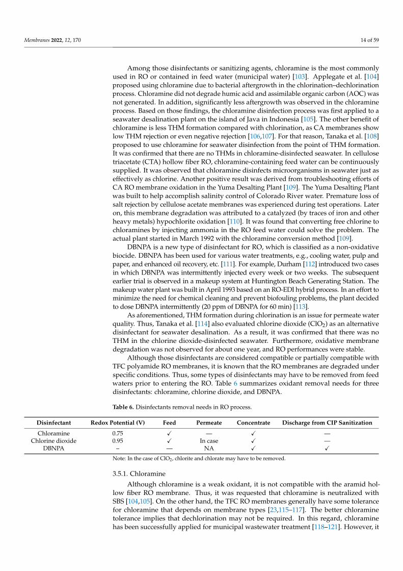
Although those disinfectants are considered compatible or partially compatible withTFC polyamide RO membranes, it is known that the RO membranes are degraded underspecific conditions. Thus, some types of disinfectants may have to be removed from feedwaters prior to entering the RO. Table 6 summarizes oxidant removal needs for threedisinfectants: chloramine, chlorine dioxide, and DBNPA.
Table 6. Disinfectants removal needs in RO process.
Disinfectant Redox Potential (V) Feed Permeate Concentrate Discharge from CIP Sanitization
Chloramine 0.75 X — X —Chlorine dioxide 0.95 X In case X —
DBNPA – — NA X X
Note: In the case of ClO2, chlorite and chlorate may have to be removed.
3.5.1. Chloramine
Although chloramine is a weak oxidant, it is not compatible with the aramid hol-low fiber RO membrane. Thus, it was requested that chloramine is neutralized withSBS [104,105]. On the other hand, the TFC RO membranes generally have some tolerancefor chloramine that depends on membrane types [23,115–117]. The better chloraminetolerance implies that dechlorination may not be required. In this regard, chloraminehas been successfully applied for municipal wastewater treatment [118–121]. However, it
Membranes 2022, 12, 170 15 of 59
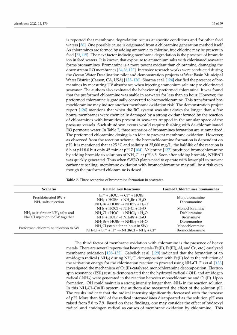
is reported that membrane degradation occurs at specific conditions and for other feedwaters [36]. One possible cause is originated from a chloramine generation method itself.As chloramines are formed by adding ammonia to chlorine, free chlorine may be present infeed [23,115]. The next factor inducing membrane degradation is the presence of bromideion in feed waters. It is known that exposure to ammonium salts with chlorinated seawaterforms bromamines. Bromamine is a more potent oxidant than chloramine, damaging thedownstream RO membranes [34,36,122]. Intensive research works were conducted duringthe Ocean Water Desalination pilot and demonstration projects at West Basin MunicipalWater District (Carson, CA, USA) [123–126]. Sharma et al. [124] clarified the presence of bro-mamines by measuring UV absorbance when injecting ammonium salt into pre-chlorinatedseawater. The authors also evaluated the behavior of preformed chloramine. It was foundthat the preformed chloramine was stable in seawater for less than an hour. However, thepreformed chloramine is gradually converted to bromochloramine. This transformed bro-mochloramine may induce another membrane oxidation risk. The demonstration projectreport [126] mentions that when the RO system was shut down for longer than a fewhours, membranes were chemically damaged by a strong oxidant formed by the reactionof chloramines with bromides present in seawater trapped in the annular space of thepressure vessels. Such shutdown events would require flushing with de-chloraminatedRO permeate water. In Table 7, three scenarios of bromamines formation are summarized.The preformed chloramine dosing is an idea to prevent membrane oxidation. However,as observed from the reaction scheme, the bromochloramine formation is dependent onpH. It is mentioned that at 25 ◦C and salinity of 35,000 mg/L, the half-life of the reaction is8 h at pH 8.0 but only 45 min at pH 7 [104]. Valentine [127] produced bromochloramineby adding bromide to solutions of NH2Cl at pH 6.5. Soon after adding bromide, NHBrClwas quickly generated. Thus when SWRO plants need to operate with lower pH to preventcarbonate scaling, membrane oxidation with bromochloramine may still be a risk eventhough the preformed chloramine is dosed.
Table 7. Three scenarios of bromamine formation in seawater.
Scenario Related Key Reactions Formed Chloramines Bromamines
Prechloirnated SW +NH4 salts injection
Br− + HOCl→ Cl− + HOBrNH3 + HOBr→ NH2Br + H2O
NH2Br + HOBr→ NHBr2 + H2O
MonobromamineDibromamine
NH4 salts first or NH4 salts andNaOCl injection to SW together
NH3 + HOCl→ NH2Cl + H2O MonochloramineNH2Cl + HOCl→ NHCl2 + H2O DichloramineNH3 + HOBr→ NH2Br + H2O Bromamine
NH2Br + HOBr→ NHBr2 + H2O Dibromamine
Preformed chloramine injection to SW NH2Cl (stable for an hour in SW) MonochloramineNH2Cl + Br− + H+ → NHBrCl + NH4 + Cl− Bromochloramine
The third factor of membrane oxidation with chloramine is the presence of heavymetals. There are several reports that heavy metals (Fe(II), Fe(III), Al, and Cu, etc.) catalyzedmembrane oxidation [128–132]. Gabelich et al. [129] indicated that the formation of anamidogen radical (·NH2) during NH2Cl decomposition with Fe(II) led to the reduction ofthe activation energy for the chlorination reaction to proceed using NH2Cl. Fu et al. [133]investigated the mechanism of Cu(II)-catalyzed monochloramine decomposition. Electronspin resonance (ESR) results demonstrated that the hydroxyl radical (·OH) and amidogenradical (·NH2) were generated in the reaction between monochloramine and Cu(II). Uponformation, ·OH could maintain a strong intensity longer than ·NH2 in the reaction solution.In this NH2Cl–Cu(II) system, the authors also measured the effect of the solution pH.The results indicate that the radical intensity significantly decreased with the increaseof pH. More than 80% of the radical intermediates disappeared as the solution pH wasraised from 5.8 to 7.9. Based on these findings, one may consider the effect of hydroxylradical and amidogen radical as causes of membrane oxidation by chloramine. This
Membranes 2022, 12, 170 16 of 59
result is consistent with the report by Cran et al. [132]. Degradation of RO membraneswas evaluated in the presence of heavy metals (Al3+, Fe2+, Al3+/Fe2+, and Cu2+). It wasobserved that the stability of chloramine solutions in the presence of metal ions decreasedsignificantly with Cu2+ and a combination of Al3+/Fe2+. The presence of Cu2+ withchloramine significantly accelerated the reduction of the amide (II) absorbance (1540 cm−1)of the polyamide RO membrane. As for remediation methods relating to membraneoxidation, Gabelich et al. [134] reported the effect of citric acid as a chelating agent for Al3+.When a chelating agent (citric acid, 5 mg/L) was added to the RO feed (1.5–2.5 mg/Lchloramines present), the loss in productivity and selectivity was arrested. In this case,citric acid may act as both a radical scavenger and a chelating agent [135]. It is known thatsome types of antiscalants have a role in chelating action. This information might be a hintto understand successful cases in some surface and ground water treatment plants wherechloramine disinfection has been applied together with antiscalants.
In this section, the mechanism of membrane degradation by chloramine was discussed.It is becoming clearer how to prevent membrane oxidation. However, it appears that thereare still unexamined and unsolved issues. Thus, it might be better to consider eliminat-ing chloramine prior to reaching RO membranes, except for in municipal wastewaterapplications [36,136].
Another area of a need for chloramine removal is from RO brine. Due to concernabout the environmental impact of discharge water, chloramine removal may be requestedfrom local municipalities [137]. For example, the Murrumba Downs Advanced WaterTreatment Plant in Queensland, Australia, implemented dechloramination of RO brinebefore discharge [138]. Dechloramination was achieved by SBS injection. The treated ROconcentrate is captured in a storage tank and then discharged with the effluent from thewastewater treatment plant.
The dechloramination methods are quite similar to dechlorination. Dechloraminationis typically accomplished by either SMBS/SBS or AC in RO [36]. The reactions of SBS andSMBS with monochloramine are as follows:
NaHSO3 + NH2Cl + H2O→ NaHSO4 + NH4Cl (10)
Na2S2O5 + 2NH2Cl + 3H2O→ 2NaHSO4 + 2NH4Cl (11)
Stoichiometrically 2.0 mg of SBS or 1.85 mg of SMBS removes 1.0 mg of monochlo-ramine. It is said that the reaction for SBS is rapid and as fast as the neutralization ofchlorine [104]. Basu and Souza [39] measured the dechloramination rate with SBS and com-pared it with dechlorination. The removal of monochloramine using a 3× stoichiometricdosage of SBS occurred quickly, with a completion time of approximately 32 s comparedto 42 s for the control free chlorine solution. However, Ekkad and Huber [139] reportedcontradicting reaction times. In their report, the following calculated reaction times wereindicated for chlorine and chloramine (1 µM concentrations):
• Free chlorine (pH < 11.0): 13 ms;• Free chlorine (pH > 11.0): 4.3 s;• Monochloramine (pH 4.0): 1.8 s;• Monochloramine (pH 8.0): 2.0 min.
As observed, the reaction time is pH dependent. Dechloramination reactions are rapidat low pH 4.0. But at slightly alkaline pH, the reaction of sulfite with chloramine is muchslower (2.0 min). Relating to this phenomenon, Comb [140,141] reported case studies whereSBS was added for dechloramination upstream of polyamide (PA) membrane RO systems.In the cases of higher pH 8.5, SBS proved to be ineffective at reducing chloramines and thenmaintaining an entirely reduced state. Thus, operating at higher pH resulted in membraneoxidation, as evidenced by higher salt passage. However, when the feed pH is acidic, SBSeffectively reduced 4 ppm of chloramines to the point where PA membrane oxidation isavoided for more than 3 years. Thus, the author concludes that pH most likely plays a vitalrole in reacting chloramines and bisulfite.
Membranes 2022, 12, 170 17 of 59
Although there exist some anomalous points for dechloramination chemistry by SBS,the following measures should be taken into consideration: taking enough contact timewith complete mixing, adjusting feed pH, and monitoring the ORP readings.
3.5.2. Chlorine Dioxide (ClO2)
Although ClO2 is considered less oxidative in nature and applicable to polyamideRO membranes, there are some conflicts about the compatibility of chlorine dioxide andpolyamide membranes. This ambiguity might be a stumbling block to applying ClO2 toRO. Kucera [36] summarizes limitations and precautions using ClO2 to RO. Potential risksand issues using chlorine dioxide are as follows:
• A risk of containing residual chlorine (preparation issue) [68];• Strong oxidant generation when bromide ion is contained in feed waters (e.g., seawa-
ter) [142,143];• Membrane oxidation at higher pH (e.g., >pH 8.0) [144–146];• Effects of heavy metals catalyzing the membrane oxidation [147];• Free chlorine/bromine generation in the presence of natural organic matter (NOM) [148].
It seems ClO2 itself has a less oxidative capability for RO. However, additional factorsmay accelerate membrane degradation, such as pH, bromide ion, and NOM, etc. It is gen-erally said that ClO2 does not oxidize bromide to bromine or hypobromite [149]. However,some reports demonstrate that bromide ion contributes to RO membrane deterioration,as observed in the chloramine cases [142,143]. Sandín et al. [142] measured the effect offeed compositions: pure water, NaCl solution, and seawater. They observed a noticeablesalt rejection decline when ClO2 was present in seawater. The bromine atom was detectedfrom the seawater ClO2-treated membrane sample by the X-ray photoelectron spectroscopy(XPS) analysis. They speculated that the behavior difference from that observed in pure waterand NaCl solution is related to the bromide content of seawater. Mizuta [143] also mentionedthat ClO2 oxidized bromide when the bromide concentration exceeded that of ClO2.
The next factor affecting RO membrane performance is feed pH. It has been recognizedthat higher pH exposure results in a more significant loss of salt rejection [36]. Alayemiekaand Lee [144] evaluated the effect of ClO2 on RO membrane characteristics at differentpH. They observed that the salt rejection was apparently decreased after 100 ppm·h ClO2contact (20 ppm × 5 h) at pH 9.0. Further, the membrane surface composition immersedat pH 9.0 was considerably different from those treated at neutral or acidic conditions.Kim [145] conducted similar experiments with wider pH ranges: pH 4.0, 7.0, 10.0, and 12.0.At higher pH conditions, it was confirmed that ClO2 heavily damaged RO/NF membranes.The scanning electron microscopy (SEM) analysis observed that the thin film polyamidelayer almost disappeared for a sample treated at 100 ppm·h ClO2 contact (100 ppm × 1 h)at pH 12.0. As observed by Alayemieka and Lee, the chlorine content of the polyamidelayer treated with pH 10.0 and 12.0 is less than those for pH 4.0 and 7.0 samples. It wasalso confirmed that despite very low contact (5 ppm·h, ClO2) at pH 12.0, the polyamide NFmembrane was chemically attacked. As less chlorine atoms were detected at pH 10.0 and12.0, a hypochlorite (OCl−) attack may not be considered a cause of membrane degradation.Regarding the membrane degradation at high pH, Kim postulated the role of hydroxylradical (·OH) and conducted an additional experiment using benzoic acid as an OH radicalscavenger. However, in this method, ·OH radical was not detected.
ClO2 + OH− → ClO2− + ·OH (12)
In this regard, Marcon et al. [146] utilized electron paramagnetic resonance (EPR)spectroscopy based on the spin-trapping technique to identify the mechanism of ClO2decomposition in an alkaline medium. They confirmed the presence of hydroxyl radicals(·OH) at alkaline pH with this method. They speculated that the generation of ·OH couldbe one reason for cellulose degradation by ClO2 at alkaline pH. The ·OH radical formationcould well explain the intense attack on polyamide membranes at higher pH. However,
Membranes 2022, 12, 170 18 of 59
as there are still unclear points about the mechanism of membrane degradation, furtherstudies might be needed.
The last unknown factor is the effect of NOM contained in feed waters. It is said thatfree available chlorine (FAC) is formed during the oxidation of organic compounds withClO2. Hupperich et al. [148] evaluated the effect of NOM and some model compounds,including phenols and olefins. When treating the Suwannee River NOM solution (5 mg/LDOC) with ClO2, it was observed that a fair amount of free available chlorine (22%) isformed in addition to the following products, chlorite (63%), chloride (8%), and chlorate(5%). Although there is no systematic analysis of the effect of NOM on RO systems, greatcare may be required when dealing with higher TOC waters.
Up to this point, several potential risks using ClO2 as a disinfectant to RO werereviewed. Although there are some clear benefits to using ClO2, one should be cautiousabout using ClO2 for continuous dosing or sanitization to RO until further investigation isconducted. Otherwise, it is recommended to remove all ClO2 prior to RO [36]. For example,the Tampa Bay Seawater Desalination plant implemented a unique double disinfectionprocess in which ClO2 is injected into the feed intake to address issues of green musselgrowth and THM formation [150]. Chlorine is dosed as the process disinfectant. SBS isused to remove ClO2 and residual chlorine.
Another issue using ClO2 to RO is the formation of DBPs, the chlorite ion (ClO2−),
and chlorate ion (ClO3−). It is known that soon after ClO2 is added to water, approximately
50–70% of ClO2 is immediately converted to ClO2− and ClO3
− [114,151,152]. In Japan,chlorate is regulated at a concentration of 0.6 mg/L for drinking water. The World HealthOrganization (WHO) recommends a chlorite and chlorate limit of 0.7 mg/L each. As bothClO2
− and ClO3− could be well removed by RO, the RO permeate quality may not be
concerning. However, when discharging the RO brine containing ClO2, ClO2−, and ClO3
−
to an environmentally sensitive area, such as marine reserves, ClO2 and its DBPs may haveto be removed.
Regarding the effect of ClO2− and ClO3
− ions on the RO membrane, Ferrero et al. [153]conducted laboratory tests to determine the resistance of various polyamide RO membraneson water solutions containing 100 mg/L of ClO2
− or ClO3−. In the tests, the membranes
were also characterized by FTIR-ATR after the treatment. There was no sign of a chemicalattack for the polyamide active layer. The membrane performance did not change after35,000 ppm·h (100 ppm × 350 h) contact. Thus, when ClO2 needs to be removed fromwaters containing ClO2
− or ClO3− ions to protect RO, the ClO2 removal itself may be of
more concern.Chlorine dioxide removal can be done by sulfites, thiosulfate, activated carbon, and
ferrous salts. The reactions of sodium sulfite and sodium thiosulfate with ClO2 are asfollows [36]:
5Na2SO3 + 2ClO2 + H2O→ 5Na2SO4 + 2HCl (13)
5Na2S2O3 + 8ClO2 + 9H2O→ 10Na2HSO4 + 8HCl (14)
Based on these reactions, theoretical dosages for different sulfites and thiosulfate aresummarized in Table 8.
Table 8. Theoretical sulfites and thiosulfate dosages for chlorine dioxide removal.
Sulfites Molecular Weight Theoretical Dosage to Remove 1 mg ClO2 (mg)
Sodium sulfite 126.1 4.67SBS 104.1 3.85
SMBS 190.2 3.52Sodium thiosulfate 158.11 1.46
The reaction of sulfites with ClO2 is rapid. Ekkad and Huber [139] reported that thereaction time of sulfites are 0.1 s at pH 9.0 and 11.0, respectively, and are comparable tothat of chlorine. Suzuki and Gordon [154] measured the chlorine dioxide-S(IV) reaction
Membranes 2022, 12, 170 19 of 59
with a slight excess of S(IV). They observed that the reactions were relatively rapid suchthat they were finished within 5 s. The same results are observed in the unexamined patentpublication [155] (JPH0929075A). A total of 0.6–1.0 mg/L ClO2 is dosed to seawater andthen supplied to cellulose acetate RO. As a result, 0.1–0.3 mg/L of residual ClO2 is detectedin the RO permeates. By injecting 0.5–0.8 mg/L of SBS into the permeate water, the residualClO2 is eliminated after 5 min of contact. Based on these findings, it seems that a slightexcess amount of SBS is enough to remove residual ClO2 from RO feed waters.
However, a new problem emerges when ClO2− ion needs to be removed from feed
water and RO brine by SBS. ClO2− can be reduced to chloride by sulfite ion, and this
reaction is efficient when the pH is between 5.0 and 6.5. The reaction slows markedly at pHabove 7.0 and is too slow for water treatment at very high pH values [114,151,156]. With a10-fold excess of the sulfite ion, and a ClO2
− residual of 0.5–7.0 mg/L, complete removalof the ClO2
− occurred in less than 1 min at pH values less than 5.0. At pH 6.5, less than15 min was required. Thus, the excess amount of SBS should be added in order to completethe reaction within 5–10 min. This excess SBS dosing creates other critical problems: strongoxidant generation from SBS and increase of ClO3
− concentration. As described later,under specific conditions, such as heavy metal (Cu and Co) presence in feed waters, astrong oxidant is generated when an excessive amount of SBS exists. Tanaka et al. [114]observed that SBS generated oxidizing agents with a 5-min contact period when 10 mg/Lof SBS was added to RO brine water, where ClO2 and ClO2
− concentration is about0.1 mg/L and 0.6 mg/L, respectively. To address this issue, they proposed to use sodiumthiosulfate. Sodium thiosulfate reduced chlorite ion to chloride at the neutral pH (6.7–7.2)in RO brine water without forming oxidizing agents. Doñaque et al. [157] investigatedthe effect of using ClO2 for seawater desalination treatment and on the DBPs. This studyevaluated ClO2 and ClO2
− removal capability with SBS for seawater and 100 µg/L ofCu(II)-spiked seawater. In the case of seawater, it was observed that both ClO2 and ClO2
−
concentrations were increased. Concentration of ClO2 was increased from 0.4 mg/L to0.97 mg/L after dosing 10 mg/L of SBS. This result does not seem to match the previousdata by Tanaka et al. [114]. In their report, an unknown oxidant was generated rather thanClO2, and ClO2 concentration was not increased. This might come from differences inthe ClO2 concentration analysis method. As for the effect of Cu(II) ion, similar resultswere observed in which both ClO2 and ClO2
− concentrations were increased. However,compared with seawater, a noticeable increase of ClO2
− ion concentration was observed.Furthermore, the ORP value was increased to 752 mV even though 10 mg/L of SBS wasadded. The author postulated that the Cu(II) ion catalytically oxidizes the bisulfite ions intopersulfate or peroxodisulfate anions, which simultaneously regenerate ClO2 and increaseClO2
− ion concentration from the high concentration of chlorides in seawater. [157]. Thus,care must be taken not to make the RO membrane deteriorate when adding excess SBS toremove ClO2 and ClO2
−, especially to RO feed. Careful ORP monitoring is essential forboth feed and brine in this situation.
Another issue is an increase of ClO3− concentration when adding excessive SBS. This is
the case of a pilot test conducted at the Evansville Water and Sewer Utility. Griese et al. [158]reported the bench-scale test results in which excessive sulfur dioxide (25 mg/L of SO2)was applied to treat waters with a variety of ClO2 dosages. It was observed that oxygenatedwater supplies containing ClO2
− formed ClO3− when treated with SO2. Although com-
plete reduction of residual ClO2 and ClO2− was achieved after 30 min of contact time, a
marked increase in ClO3− concentration was consistently observed. The same result was
observed in a lab test using SMBS. This contradicts the previous results obtained for waterswith the absence of oxygen. In the absence of oxygen, a chlorite removal reaction withsulfite followed the reaction to produce sulfate and chloride, and no ClO3
− is formed [151]:
2SO32− + ClO2
− → 2SO4− + Cl− (15)
Griese et al. [158] mentioned that these reactions are complicated for oxygenatedwaters. Several different pathways result in the reduction of ClO2
− to chloride ion and
Membranes 2022, 12, 170 20 of 59
the formation of ClO3− as an unwanted inorganic by-product. They pointed out that the
potential benefits associated with the use of SO2/SO32− for the reduction of DBPs appear
to be severely limited.Again, this phenomenon could be partially explained by autoxidation reactions of
sulfite in the presence of oxygen in which strong oxidants and radicals are generated, asdiscussed in Section 8.
In summary, to remove ClO2 and ClO2− within an acceptable reaction time at neutral
pH, an excessive amount of SBS may have to be injected. However, this results in risksgenerating strong oxidants and increasing ClO3
− ion. To avoid those risks, using thiosulfateinstead of SBS might be an option. The other option is to use ferrous salts injection for RObrine or prior to a media filter or LP membranes [159]. When treating RO brine containing0.3 mg/L of ClO2 and 0.9 mg/L of ClO2
− with 10 mg/L of ferrous ammonium sulfate, bothClO2 and ClO2
− are removed without forming the ClO3− ion [155]. Doñaque et al. [157]
reported the ion Fe(II) is oxidized to Fe(III) in a fast reaction that results in eliminating Cl2,ClO2, and ClO2
− and producing FeCl3, which can act as an effective coagulant.
3.5.3. 2,2-Dibromo-3-nitrilopropionamide (DBNPA)
DBNPA is a non-oxidative biocide that can be used for RO continuously or inter-mittently. Furthermore, a high concentration of DBNPA could be used for RO systemsanitization after CIP. However, when discharging RO brine or sanitizing effluent to envi-ronmentally sensitive areas, DBNPA may have to be removed. Elimination of DBNPA isaccomplished by dosing SBS [160,161]. Reduction by SBS yields cyanoacetic acid and twoequivalents of bromide ions [162].
N≡C-CBr2-CONH2+ 2NaHSO3 + 2H2O→ N≡C-CH2-CONH2 + 2H2SO4 + 2NaBr(DBNPA) (Cyanoacetamide)
(16)
Boorsma et al. [163] reported the IMS surface water treatment plant in Klazienaveen,the Netherlands. They reported that intermittent dosing of DBNPA successfully controlledbiofouling. DBNPA was neutralized before the discharge in the wastewater pond andsubsequent release into the surface water. SBS was applied for neutralization, and ORPwas used to monitor adequate neutralization.
4. Preservative for New RO Elements and Storage in Plant Shutdown
After dechlorination, membrane preservation is the second most-used application ofsulfites in the RO process. Preservation of the RO elements is essential in two areas: thepreservation of new RO elements and storage during plant shutdown. First of all, the newRO elements are shipped with a preserving solution to prevent biofouling. In the past,a 0.3–1.0 wt% solution of formaldehyde was commonly used as a shipping solution forCA RO elements [164–166]. However, due to a concern about health effects as a potentialoccupational carcinogen, formaldehyde has been obsoleted in the RO process.
When the polyamide hollow fiber RO was developed, the RO modules were treatedwith a 0.25 wt% SMBS and 18 wt% glycerine solution prior to shipment [167]. By followingthis procedure, TFC polyamide spiral RO elements were shipped with a solution of 20 wt%glycerine and 1.0 wt% SBS (food grade) [168,169]. This solution also protects from freezedamage. Later on, glycerine was switched to propylene glycol, and then propylene glycolwas eliminated from the shipping solution. The role of SMBS is a biostatic agent to preventbacterial growth within the RO elements. In addition, SMBS acts as the oxygen scavenger.As the polyether composite RO (PEC-1000) is less tolerable to oxygen, sulfites and aniron-based oxygen scavenger were evaluated to protect the RO membrane [170]. It wasreported that 0.5% SMBS and deoxidizer packets kept the oxygen level low enough inthe RO element without changing the performance for one year. It is interesting that theiron-based deoxidizer packets evaluated at that time have presently been implemented to acertain type of RO element [171].
Membranes 2022, 12, 170 21 of 59
Most spiral-wound RO elements are currently preserved with a 0.5–1.0% SMBS so-lution in oxygen barrier plastic bags [34]. In addition, a certain type of RO element ispreserved in a buffered SMBS solution using sodium citrate to mitigate pH changes. Forstorage lasting longer than six months, preserved elements should be visually inspected forbiological growth and periodically examined every three months after that. If the preserva-tion solution appears to be murky, the elements should be re-preserved and vacuum-sealed.Another method for checking the integrity of the preservative is through pH measurements.The bisulfite in the preservative can oxidize into sulfuric acid, which will cause the pH todrop. If the pH of the preservative drops below 3, the elements must be re-preserved [172].
Next, the storage application is for the plant shutdown case. When the RO systemneeds to be shut down for longer than 48 h, necessary measures must be taken to preventmicroorganism growth. Membrane suppliers suggest such measures depending on storageperiods: short-term storage, 1–2 weeks or less, for example, and long-term storage, morethan 1–2 weeks [173–175]. For short-term storage, flushing with RO permeate or filteredfeed water is generally recommended. Regarding long-term storage, it is recommendedthat the RO elements be stored within entire RO racks or oxygen barrier plastic bags with a0.5–1.0% SMBS solution. One membrane supplier suggests using a lower concentration ofSBS solution, i.e., 500 to 1000 mg/L (maximum) [176].
As mentioned, a 0.5–1.0% SMBS solution is now commonly used as a long-termpreservative. Until now, several tests have been made to examine the storage conditions andcompare an SMBS solution with other preservatives. Here, brief chronological highlightswill be shown. As mentioned, for the polyamide hollow fiber RO, the use of 0.25% of SMBSwas recommended. Furthermore, an addition of 18 wt% glycerine was essential to preventbiological growth [167]. Larson et al. [177] reported that the best FT-30 RO membranestorage procedure is to store the element in a 0.1% aqueous SBS after various storage tests.However, later, Petersen et al. [178] reported that SBS or SMBS, used at 0.5% in water,appear preferable for shelf storage or prolonged “down” periods. Henthorne et al. [179]reported the comparison test results as a part of a cooperative research program betweenthe United States Department of Interior, Bureau of Reclamation (BR), and the Kingdom ofSaudi Arabia, Saline Water Conversion Corporation (SWCC). In this cooperative research,three types of biocides were evaluated; Minncare™ (a peracetic acid solution), Bronopol™,and SBS. The three biocides chosen for the testing were based on a screening evaluationof 13 potential biocides conducted for the Yuma Desalting Plant [166,180]. A total of 3%SBS was evaluated at the BR test with keeping the solution pH at approximately 5.5. TheSBS concentration utilized in SWCC was 400 mg/L. The SBS solution was replaced everytwo weeks and pH adjusted to 4 +/− 0.2. In the SWCC test, no salt rejection declinewas observed after 36 months of storage. On the other hand, a slight increase of thenormalized permeate flow (NPF) was observed. The cumulative testing indicated that TFCSWRO membranes stored in the three tested biocides respond in the following order ofacceptability of biocides: SBS >> Bronopol™ >> Minncare™.
When storing the RO elements with the SMBS solution, the following two pointsshould be noted: the decrease in pH of the SMBS preservative solution and the heavy metalfouling of the membrane surface. As shown in Equation (4), when SBS in the preservativecontacts with oxygen intruded into RO racks or storage plastic bags, SBS is oxidized tosulfuric acid, which will cause the pH to drop. In this regard, several tests were conductedto elucidate the effect of pH. The Naval Facilities Engineering Service Center (NFESC)conducted a three-year test program to evaluate the effectiveness of seven preservatives forTFC SWRO membranes. A 1% SBS and 18% propylene glycol solution was also evaluatedas a generic storage solution. It was reported [175] that the SBS-based preservative wasparticularly detrimental to salt rejection performance. The preserved elements had a dropin normalized salt rejection greater than 0.30%, while the control group declined about0.25%. This result contradicts the previous results on membrane compatibility. In theNFESC test, the average SBS solution pH was 3.17, lower than the BR and SWCC tests.Although the authors did not touch on the pH effect, this might be a potential cause of
Membranes 2022, 12, 170 22 of 59
the salt rejection decline. To avoid the pH changes during storage, Ventresque et al. [181]decided to put the membranes into bags and preserve them with SBS, which was addedphosphate buffer to stabilize the pH, thus avoiding frequent refills of preservative solution.After eight months of storage, membranes are fitted again in the pressure vessels, rinsed,and returned to service. No degradation of the permeability or retention was observed.
Tu et al. [182] evaluated three preservatives, namely formaldehyde, SMBS, and DBNPA.SMBS at 5% and formaldehyde preservative solutions adjusted to either pH 3.0 or 7.0 wereused for a 14 days storage test. When the pH of the SMBS and formaldehyde solutions wasreduced to 3.0, prominent boron and sodium rejection declines were observed. The authorssuggest a near-neutral pH (i.e., pH 7.0) is necessary to avoid significant negative impacts onmembrane performance using SMBS. In addition, some changes in the membrane surfaceproperties (zeta-potential and FT-IR absorbance) were also observed. Apart from the ROmembrane degradation by SBS, Ventresque et al. [183] reported an adverse effect to pressurevessels at low pH. They found that even though pH was above 3.0 in the water body duringpreservation, lower pH had been induced in the air trapped within the pressure vesselsabove the SBS solution. Acid attack weakens the resin and the glass fiber, which then crackseasily under low stress.
Thus far, the effect of pH of the SBS solution on the RO performance during storagewas reviewed. It is confirmed that SBS solution pH less than 3.0 has a phenomenologicallynegative impact on RO. However, it seems that the mechanism and cause of deteriorationof membrane performance are still not clear, and it may need further tests to know whichpH level is safe for long-term storage from a practical point of view.
The next factor to be considered is the effect of heavy metal fouling on the RO mem-brane surface during storage. It is reported [184] that the rejection performance deterioratedwhen heavy metal-fouled RO membranes were stored in an SBS solution. The inventorsfound that in a system in which heavy metals, such as copper and chromium, are presentin RO membranes, SBS generates an oxidizing substance that results in membrane degrada-tion. Furthermore, it was found that the deterioration of membrane performance could besuppressed by adding a small amount of a chelating agent. Farooque et al. [185] reportedthat the polyamide hollow fiber RO encountered the problem of high permeate conductivityin some of the BWRO membranes, which were preserved in SBS solution for about 23 daysdue to plant shutdown for annual maintenance. From the SEM-EDX analysis, a high levelof Fe and Cr was detected from the fiber surface. Furthermore, oxidative degradation wasconfirmed by measuring the polyamide intrinsic viscosity. However, the authors suspectedthat the membrane could have been accidentally exposed to chlorine.
Ventresque et al. [183] summarized the storage methods by SBS as follows:
• Clean membrane before applying SBS.• Immerse membranes in the preservation solution directly in the pressure vessels.• Vent the air from the system and isolate the system.• Check pH during preservation to monitor the degradation of the preservation solution.• Change preservation solution if pH is below 3.0.• Change preservation solution every 30 days if the temperature is below 27 ◦C and
15 days if the temperature is above 27 ◦C.
Cleaning should be an essential step to remove heavy metals and prevent membranedegradation. Venting air and isolating the system can minimize the SBS oxidation and de-crease pH. A regular pH check is imperative to confirm the SBS storage solution conditions.Additionally, adding chelating agents into the preservative might be an option to preventmembrane oxidation [174]. When using sodium citrate, this chemical may have the tripleroles acting as a buffer, a chelating agent, and a radical scavenger.
As mentioned, SMBS is now the most commonly utilized preservative in RO plantsduring shutdown. It is a cheap and efficient preservative, but its tendency to oxidize easilyhas several drawbacks: a need for regular pH checks, isolation of the RO system fromthe air, and an odor issue due to SO2 gas release, etc. [186]. Therefore, studies have beenmade to apply non-oxidative biocides as membrane preservatives. Majamaa et al. [186]
Membranes 2022, 12, 170 23 of 59
conducted long-term preservation trials by using three different non-oxidative biocides:DBNPA, 5-Chloro-2-methyl-4-isothiazolin-3-one (CMIT)/2-Methyl-4-isothiazolin-3-one(MIT) CMIT/MIT, 2-Octyl-2H-isothiazol-3-one (OIT) as well as SMBS as a reference chemi-cal. It was demonstrated that the biocides can be equivalent preservatives to SMBS andthat the application is economically feasible.
Regarding DBNPA, Tu et al. [182] also evaluated its compatibility with TFC ROmembranes. They found that salt rejections (boron and Na ion) declined at neutral pH(pH 7.0). However, it is noted that the concentration of DBNPA (1%) used is much higherthan that (60 ppm) used by Majamaa et al.
The non-oxidative biocide, CMIT/MIT, was applied to the Camp de Tarragona-Vilaseca Water Reclamation Plant, Spain, for nearly ten months of storage [187,188]. Priorto applying the CMIT/MIT, a complete CIP was conducted with caustic and acid cleaningsolutions. Then, the biocide was added by recirculating feed water containing 15 mg/Lof CMIT/MIT through the RO pressure vessels. After six months, RO pressure vesselswere drained, and a new biocide solution was put in place. An evaluation of performancebefore and after shutdown demonstrated that membrane performance after the extendedshutdown was similar to new performance during the commissioning period [189]. Theisothiazoline-based biocide was also applied to the Barcelona SWRO Plant [190].
5. Deoxygenation
In boiler-water treatment and oilfield production, sulfites are used as an oxygenscavenger. In a seawater distillation process, such as multi-stage flash evaporation (MSF),SBS is the most used to remove residual oxygen after mechanical deaeration [191]. In someRO applications, deoxygenation is necessary. There are two main applications applyingsulfites to remove oxygen from feed waters.
The first application is to protect an RO membrane from degradation by oxygen. Inthe late 1970s, a new TFC membrane, designated PEC-1000, was developed [192,193]. ThePEC-100 made it possible to produce potable water from seawater in a single stage with ahigh recovery operation. However, as the PEC-1000 membrane had no chlorine and oxygenresistivity, it was necessary to eliminate the dissolved oxygen (DO) by SBS [26,194,195].DO was requested to be reduced to 0.5 mg/L or less. Thus, 80 ppm of SBS was dosed for along-term field test. The required SBS to remove saturated DO 8 mg/L and 0.5 mg/L ofresidual chlorine in seawater is 53 mg/L. It was reported that SBS injection reduces the pHof seawater to 7.0 or less, which resulted in eliminating sulfuric acid injection. Later, tosave a chemical cost, an application of a vacuum deaeration system was proposed. ThusSBS dosing amount was reduced to 20 ppm by installing a vacuum deaeration tower [196].
Due to a lack of information on the SBS-oxygen reaction in seawater, Matsuka et al. [197]investigated factors affecting seawater reaction rate. They evaluated the following factors:salinity, pH, temperature, copper ion, and ethylenediaminetetraacetic acid (EDTA). It wasfound that the reaction in seawater is much faster than that in pure water. For example, inseawater containing 3.5% salinity at 26 ◦C, 6 ppm of DO was decreased to almost 0 ppm inabout 3 min by dosing 55 ppm SBS. The pH also has a strong effect on the reaction rate.The reaction rate at pH = 6.5 is the highest and about four times as high as that at pH = 5.0.In addition, the positive catalytic effect of copper ions and the negative catalytic effect ofEDTA in seawater were observed.
Although the PEC-1000 had high salt and low molecular weight organics rejections,the PEC-1000 was replaced with the TFC polyamide RO membranes. As the performance ofthe TFC polyamide membrane is not affected by DO, deoxygenation is not necessary [198].Thus, the oxygen removal in RO application might be of historical interest. However, theinformation on the oxygen scavenging with SBS is still valuable when considering thecause of membrane deterioration in an SBS/O2 system mentioned in Section 8.
The next application of deoxygenation is for anaerobic groundwater. In groundwater,sometimes high levels of iron and manganese ions are contained. Once these ions arecontacted with oxygen, colloidal iron- and manganese hydroxides/oxides are generated,
Membranes 2022, 12, 170 24 of 59
which are a cause of RO fouling. Thus, iron and manganese have to be removed in apretreatment process. The aeration/chemical oxidation followed by filtration has beenwidely applied [34]. Manganese greensand filtration is one method of providing both ironremoval and filtration. However, some reports have shown that direct anaerobic filtrationcould eliminate iron and manganese fouling [199–201]. For example, Beyer et al. [202]reported long-term performance (six and ten years) and fouling behavior of four full-scaleNF plants in the Netherlands that treat anoxic groundwater. In addition, it was reported thatstandard acid-base cleanings (once per year or less) were sufficient to maintain satisfyingoperation during direct NF of the iron-rich (≤8.4 mg/L) anoxic groundwaters.
For a successful operation with direct filtration, air intrusion should be prevented.However, completely avoiding the air intrusion to RO/NF systems might be difficult.Therefore, lowering the feed pH might be one of the measures to cope with such an event.Hart and Messner [203] mention the reasons that low pH operation eliminates the need todose a threshold scale inhibitor, slows the rate of iron oxidation, and increases the solubilityof any iron oxidation products that did form. Castle and Harn [200] explain that at pHvalues greater than 5.5, the rate of oxygenation of Fe2+ increases by 100 times per pH unit.Therefore, to minimize the chance of iron oxidation, sulfuric acid is added upstream of themembrane system to lower the feed water pH from 7.2 to 5.5 pH units in the PinewoodsWater Treatment Plant in Lee County, FL, USA.
Another option to deal with oxygen intrusion is to add a small amount of SBS. Such acase has been first reported in the Coalinga desalination plant. It is well known that theworld’s first large-scale desalination plant using RO was built in California in 1965 at theCoalinga desalination plant [204–206]. After startup, several steep declines in productionrate occurred due to deposition of ferric hydroxide. It was observed that the feed watercontained about 50% saturated DO [205]. Therefore, an oxygen scavenger was added to thefeed water to remove the DO and maintain the dissolved iron in the more soluble ferrousoxidation state. Dosing with catalyzed SBS for this purpose was initiated and was foundsuccessful in reducing the fouling rate. However, in July 1966, the addition of SBS wasstopped from a concern of the chemical cost increase. It should be noted that, currently,using catalyzed SBS is not recommended due to a membrane degradation problem.
Yallaly et al. [207] reported the actual BWRO plant design where the feed groundwaterhas a TDS concentration of 1150 to 2200 mg/L and has high concentrations of dissolvediron and manganese. Therefore, in addition to lowering feed pH by sulfuric acid, theydecided to add SBS in front of RO to treat such feed water directly.
Other cases have been observed in an ion exchange (IEX) softening process using ROpretreatment. Dissolved ferrous iron contained in anaerobic groundwater is effectivelyremoved by standard softening resin [208]. Martin and Kartinen [209] reported the pilottest data to treat groundwater characterized by high TDS content, hardness, and iron andmanganese. The combination ion exchange softening and RO process was selected forthe pilot test. Although the system was operated in a fashion to exclude air as much aspossible, the resin capacity loss was observed and attributed to iron fouling. As well waterwas pumped directly into the IEX column with no air contact, thus it was speculated thatthe source of oxygen was the regenerant. To prevent oxidation by the regenerant, SBS wasadded to the regenerant just before regeneration. This method is expected to benefit fromconverting the adsorbed ferric iron to more soluble ferrous iron. After taking this measure,the pilot system was operated for 36 regeneration cycles using this regeneration scheme.Over this period of operation, no loss of resin capacity was observed.
The following example is a case study producing process water (160 m3/h capacity)in a Ukrainian brewery [210]. The IEX-RO hybrid design was selected to cope with ahigh level of iron and manganese contained in a groundwater feed. A weak acid cationresin (WAC as H-form) was selected as a softening resin. After taking some measures toavoid air contact, 3–5 ppm of SBS was dosed in the feed water storage tank. As a result,it was reported that the frequency of chemical cleaning of RO elements was significantly
Membranes 2022, 12, 170 25 of 59
decreased to once per 6 months compared with the old system (twice a month), relying onthe convention oxidational and filtration process.
Finally, in this section, when applying SBS as an oxygen scavenger in RO processes,there are some points to keep in mind. Bornak [211] raised an issue that sulfite chemistrywould probably interfere with other operations at the plant and could pose dischargeproblems. Overdosing SBS for dechlorination and deoxygenation may cause reducedoxygen levels in the RO brine. Thus, when discharging the RO brine and membrane storagesolutions to environmentally sensitive areas, care must be taken [212–214].
6. Shock Treatment and Sanitization
SBS also acts as an antimicrobial agent [17]. In particular, SBS shows good efficacy forinhibiting the growth of aerobic bacteria as it removes oxygen from the water [36]. Basedon this biostatic characteristic, SBS has been widely utilized as an RO shipping solutionand preservative, as mentioned in Section 4. Other applications are for shock treatmentand RO unit sanitization to prevent or delay biofouling.
6.1. Shock Treatment
Shock treatment is the intermittent addition of a biocide into the feed stream duringregular plant operation for a limited period [115]. SBS is the most commonly used biocidefor this purpose. Historically, research conducted by DuPont has demonstrated that theshock treatment with SBS (500 mg/L) for 30 min twice per day was effective for thehollow fiber polyamide RO [215]. However, the efficacy of SBS as a biocide for seawater isdependent on the use concentration, the exposure time, and the type of micro-organismspresent [22,216]. For example, with an exposure time of 30 min at a concentration of500 ppm, a 99% kill rate was reported for seawater microflora. However, in another casewith a high TDS (13,000 mg/L) brackish water, the percent kill was much lower thanthat obtained with seawater—a 17% kill after 30 min contact at 500 ppm of SBS. Based onthese observations, it was suggested that the optimum dosage and exposure time must bedetermined for each site. To improve the efficacy of the SBS shock treatment, Matani andKimura [217] invented a new shock treatment method with SBS under an acidic conditionfor low TDS waters. However, as SO2 is generated at low pH, rigorous pH control andmonitoring SO2 in permeate may be necessary.
Apart from the online shock treatment, offline short-time product water-flushing wasalso proposed to enhance the plant’s availability [43]. For the hollow fiber polyamide RO, inaddition to utilizing standard product water, flushing with 5000 mg/L SBS was suggestedto suppress biofouling. This SBS flushing was applied to the SWRO plant in Jabel Dhana,United Arab Emirates [218].
For anaerobic feed water treatment, the SBS concentration was suggested to be in-creased from 500 up to 2000 mg/L and the shock treatment time from 30 min to 1 h eachtime, due to less efficiency of SBS in an anaerobic compared to an aerobic environment [219].Furthermore, anaerobic and sulfate-reducing bacteria are more resistant to SBS than aerobicbacteria. It was also suggested that RO plants are designed to avoid dead ends and stagnantareas where anaerobic bacteria can thrive. If anaerobic bacteria become a problem, offlinedisinfection and cleaning can kill and remove them from the RO system [22]. For thispurpose, quaternary ammonium salts, such as benzalkonium chloride, are reported tobe effective in disinfecting anaerobic bacteria for the PEC-1000 membrane [220]. How-ever, as quaternary germicides cause flux losses for the TFC RO membranes, quaternaryammonium salts are not recommended for use as sanitization agents [168].
Next, actual application cases of the SBS shock treatment are introduced. The firstcase is the 800 m3/d capacity demonstration SWRO plant built at Chigasaki, Japan, in1979 [26,194,221,222]. Two types of RO modules were evaluated (PEC-1000, spiral-woundmodules, and CTA hollow fiber modules). As the PEC-1000 has less tolerance of chlorineand oxygen, 80 mg/L of SBS was added to the feed seawater at the beginning. Duringoperation, it was found that differential pressure (DP) increase of the CF was much faster
Membranes 2022, 12, 170 26 of 59
than during the operation of the conventional CA spiral-wound modules. As it was thoughtthat bacteria growth within the CF under a no chlorine condition was a cause of rapid DPincrease, the SBS shock treatment was evaluated and implemented (30 min, 500 mg/L SBS,once a day). The DP increase of CF was considerably suppressed by taking this action, andthe frequency of CF exchange was extended by about two times.
Later, to minimize SBS consumption for deoxygenation, a vacuum degasifier wasinstalled. Along with this modification, the SBS dosing point was moved after the CF.However, a 500 ppm SBS shock treatment method was continued for these changes. Asa result, it was reported that the problem of microbial regrowth was resolved, and theDP increase of the reverse osmosis module was suppressed [26]. As for the PEC-1000 RO,Heyden [223] reported that 500 ppm of SBS shock treatment (twice daily) was applied to a600,000 gallon per day (gpd) SWRO plant at Tanajib, Arabian Gulf Coast.
The RO plant at Ras Abu Jarjur, State of Bahrain, with a capacity of 46,000 m3/d(10 MIGD), was built and started in October 1984 [219,224,225]. As hydrogen sulfide isexpected to be contained in the feed groundwater and colloidal sulfur might be generatedif it is allowed to contact air, the plant was planned to be operated as a closed system [225].The shock treatment with SBS was also designed on a dose rate of 500 ppm for half an houreach day. For two years of operation, it was found that the planned SBS shock treatment isless efficient in an anaerobic environment compared to an aerobic environment for bacteriacontrol. Instead, shock dosing with 1000 ppm SBS every second day was established as anoptimum bacteria control procedure [224]. Further, periodic SBS soaking of RO membraneswith an interval of 6–8 weeks was implemented.
The Boujdour RO plant in Morocco with an 800 m3/d production capacity was built totreat beach well water [226]. As a dechlorinating and bacteriostatic agent, 25 ppm SBS wasinjected continuously to upstream sand filters. Later on, shock-injecting 600 ppm of SBSwas applied for 30 min. It was found that applying this shock injection made it possibleto attain the same performance as that which has been obtained while using a 25 mg/Lcontinuous injection.
As mentioned above, while there is information that SBS shock treatment well sup-presses biofouling, there are also data that its efficacy is questionable or less successful insustaining bio growth for a long-term operation. For example, it was reported that a majorproblem at the Al-Birk SWRO plant is biological fouling, although the feed was disinfectedwith 5.2 ppm chlorine and 30 min of shock treatment every 48 h using 500 ppm SBS [59].
An SWRO desalination plant of 40,000m3/d capacity was completed in 1997 at Chatan-cho in the Okinawa Main Island. From the startup, preventing or sustaining biofouling wasone of the significant concerns in operation and maintenance. Thus, the plant had decidedto apply a shock dosing with 500 ppm SBS (30 min, once per day) into the RO feed watersince the startup of the RO plant operation [28]. However, the efficacy of sterilization hadbeen gradually decreasing though it was able to suppress the DP increase of the RO moduleeffectively at the beginning of RO operation. It became clear that the addition of SBSstimulates the growth of microorganisms, including sulfur-oxidizing bacteria, and that theSBS shock dosing cannot stop biofouling [227]. Therefore, they changed SBS shock dosingin July 1999 with sulfuric acid and started with the low pH of 2.5 to 3.0 shock treatmentfor 30 min. The sulfuric acid shock treatment was effective at the beginning. However,the sulfuric acid shock dosing also tends to decrease its effect after a long-term operation.Furuichi et al. [28] mentioned a possibility that combining two different disinfectants makesit more effective compared with only using a single disinfectant.
Kimura et al. [228] investigated a new membrane sterilization method and comparedit with the conventional shock treatment with 500 ppm SBS. They found that most marinebacteria were still alive after contacting 500 ppm of SBS for 2 h. This result does not matchthe previous results observed in seawater [22]. Next, they tested the new disinfectant andcompared it with an actual plant’s SBS shock treatment (1 h per day). It was observed that0.05 MPa increased the DP within two weeks in the SBS shock treatment. When seriousbiofouling occurred at the monitoring plant, the consumption of SBS at the RO portion
Membranes 2022, 12, 170 27 of 59
increased with the plant operation time, and the residual SBS in the brine reached almostnone, even when the SBS concentration was raised. The authors speculated that particularsulfur-oxidizing bacteria (SOB) can utilize bisulfite ion, or possibly sulfite ion, as a soleenergy source. Moreover, several bacteria in the brine were grown in a defined inorganicmedium for marine SOB by intermittently adding SBS. The authors conclude that SBSshock treatment is not effective for seawater under these circumstances.
It appears that the efficacy of SBS shock treatment depends on feed water (TDS,AOC, DO, and temperature, etc.) types and pretreatment conditions, etc., and tends to bediminished for long-term operation. Therefore, new disinfectants that enable stable shocktreatment have been investigated [228–231]. First, however, it will be necessary to evaluateits effects, impact on the environment when discharging, and whether it can be used fordrinking water during online shock treatment.
6.2. Disinfection and Sanitization
Although SBS is used as a biostatic agent to prevent bacterial growth, it is not commonto use SBS as a disinfectant. However, SBS has been used as a disinfectant or sanitizationagent under some conditions. For example, Redondo and Lomax [41] mention that SBSconcentration in the range up to 50 ppm in the feed stream of seawater RO plants hasproven effective in controlling biological fouling. In addition, colloidal fouling has alsobeen reduced by this method. However, it was also noted that this method is limited tolow- to medium-fouling potential seawater.
RO system sanitization is necessary after CIP in some food and beverage, dairy, phar-maceutical, and microelectronics industries. For this purpose, hydrogen peroxide or amixture of hydrogen peroxide and peracetic acid has been used [68,232]. For pharmaceu-tical and kidney dialysis water production, hot water sanitization is also practiced. Inspecific cases, SBS has been used as a sanitization agent. For example, McDonough andHargrove [233] evaluated three sanitizing agents (Diethylpyrocarbonate, iodophor, andSMBS) for RO/UF equipment used to concentrate and fractionate cheese whey. They recom-mended SMBS for overnight shutdown when rapid sterilization is not required. However,when SBS is used for system sanitization, removing heavy metals by acid cleaning shouldbe essential to prevent membrane degradation similar to hydrogen peroxide [161].
As mentioned, the Ras Abu Jarjur RO Plant was operated with SBS shock treatment.However, biofouling gradually built up after two years of operation and affected perfor-mance [234,235]. It was found that the primary cause was microorganisms that grew ina storage tank of sodium hexametaphosphate (SHMP). Due to the presence of hydrogensulfide, SBS was used for sanitization instead of chlorine. The optimum concentration ofSBS added to the SHMP tanks was found to be 0.25%, and this concentration was foundto control bacteria and does not affect SHMP reversion to orthophosphate. After addingSBS into the SHMP storage tank, the normalized flow rate was sustained longer. For thiskind of day tank maintenance, Byrne [236] mentions that bio growth can be prevented bydropping the pH to 4.0 by adding an acid or adding a minimum of 200 ppm of SBS.
7. Other Applications: Cleaning and pH Control
Utilizing its reducing action, SBS is also being applied for use in membrane cleaning. Thissection introduces examples of sulfites application to membrane cleaning and pH adjusters.
When dissolved hydrogen sulfide gas (H2S) contained in groundwater contacts withchlorine or DO, H2S is oxidized to elemental sulfur or sulfate. Metal sulfides are alsoformed and can be precipitated on the RO membrane surface. It is said that colloidal sulfurmay be challenging to remove, but a solution of sodium hydroxide (NaOH) with a chelatingagent, such as EDTA, is an appropriate cleaner [68]. Byrne [21] mentioned that if the foulantis not too heavily composed of elemental sulfur, an acidic solution might be capable ofdissolving out the sulfide components. It is also disclosed that a mixed aqueous solutioncontaining sodium sulfite and a wetting agent effectively removes sulfur scales from themetal surface [237]. As shown in Equation (17), sodium sulfite reacts with elemental sulfur
Membranes 2022, 12, 170 28 of 59
(S) and forms sodium thiosulfate (Na2S2O3) in an alkaline solution. Then, the elementalsulfur is dissolved and removed.
Na2SO3 + S→ Na2S2O3 (17)
Smith and Whipple [238] reported cleaning test results with SBS. When building anew RO demineralization plant in a paper mill for boiler make-up water, a pilot test wasconducted by feeding groundwater in 1987. After about two months of operation, thesystem pressure drop increased dramatically following system maintenance and possibleair intrusion. It was speculated that any air entering the system resulted in sulfur fouling ofthe membranes due to H2S presence in the feed water. Thus, cleaning with a 3% solution ofSMBS, which was pH adjusted to pH 8.2 with caustic, was conducted. It was reported thatthis CIP method was successful in reducing a pressure drop to the normal level. Later, twoelements were returned to the manufacturer for cleaning optimization and clement analysis.Then, it was found that copper sulfide was a primary inorganic foulant on the membrane.
Reiss et al. [239] evaluated pretreatment methods containing hydrogen sulfide andelemental sulfur in groundwater. One method was chemical resolubilization with SMBSprior to NF. It was found that 50 ppm of SMBS could reduce turbidity from 40 NTU to aslow as 3 NTU, representing over 90% reduction in turbidity. Thus, SBS could be used asa cleaning agent for sulfur and metal sulfides removal based on these data. However, itshould be noted that optimum SBS concentration, pH, temperature, and the effect of heavymetals, etc., needs to be identified.
For iron fouling, sodium hydrosulfite (Na2S2O4) is sometimes recommended as apreferred cleaning solution [68,240]. Byrne [21] mentions that the best chance of cleaningthe iron is to reduce it from the ferric to the ferrous state, using a strong reducing agent,such as SBS. Once reduced, the iron will readily go back into the solution at lower pH.The optimum pH is about 3.5 to 4.0. Shimizu [241] disclosed an MF membrane-cleaningmethod for iron oxide and manganese dioxide with SBS.
MnO2 + 2NaHSO3 →Mn+ + 2HSO4− + 2 Na+ (18)
The MF membrane was first cleaned with 2 wt% hydrochloric acid solution, but agood cleaning effect was not obtained. Therefore, the CIP chemical was switched to a2 wt% SBS solution. After applying the SBS solution for cleaning, the permeate flow ratewas reported to be recovered significantly.
Once before, the RO membrane chemical cleaning, which involved SBS and detergent,was used to clean the polyamide hollow fiber membranes [218]. The SBS cleaning withhigh pH was also reported in RO plants in the Netherlands [242]. SBS was used duringthe high pH cleaning to achieve anoxic conditions and improve microbial inactivation. Asmentioned, biofouling was an issue in the Okinawa SWRO plant. The sulfuric acid shocktreatment was effective in decreasing DP for a while but then became ineffective. Therefore,the plant shifted its focus on improving the CIP method. Yamashiro and Goto [243]mentioned a new cleaning procedure. Fouled RO membranes were first soaked in an SBSsolution for a fixed time and then cleaned with an alkaline solution after rinsing out theSBS solution. As a result, the DP was decreased drastically, and, consequently, long plantoperation became possible after establishing the efficient CIP method.
Regarding the effect of SBS, Yamasato [244] speculated, as follows. From past analysisresults, components, such as iron and calcium, exist together in a biofilm on the membranesurface. Thus, for example, when calcium acts as an inhibitory factor for alkaline cleaning,it is considered that the SBS solution with a pH of 3.0 to 4.0 works to remove it and enhancesthe effect of alkaline cleaning.
Ebrahim [245] reported that biomass and sulfur material sometimes are fouled togetheron RO membranes in biofouling cases. In this situation, SBS may remove sulfur compounds,such as organic and elemental sulfur and metal sulfides, before alkaline cleaning.
Membranes 2022, 12, 170 29 of 59
At the end of this section, an SBS role as a pH adjuster is introduced. As mentioned, insome cases, SBS concentration in the range of up to 50 ppm is injected to control biofouling.As a side benefit, no acid is required for calcium carbonate control because of the acidicreaction of bisulfite [41]. Olabarria [20] mentions that in some countries, where it isimpossible to have access to acid, it is usual to dose SMBS in well waters. This SBS dosingis used as a disinfectant and reduces the pH.
8. Adverse Effects of Sulfites on RO Membranes
Although SBS has been widely used in RO processes, it is reported that SBS has someadverse effects on RO membranes and processes. The following two have been reported tobe significant issues and are explained in this section.
• RO membrane oxidation;• Trigger of biofouling.
8.1. RO Membrane Degradation/Oxidation by Reducing Agents
It may sound strange to hear that reducing agents oxidize RO membranes. However,some literature has sporadically reported that some reducing agents deteriorate the ROmembrane under specific conditions. For example, the unexamined patent publication(JP2004025027A) [246] disclosed that feed water containing hydrazine (N2H2) degrades theRO membrane. Hydrazine is a strong reducing agent. A required amount of hydrazinemay be added to a cooling water system, such as a circulating cooling water system toprevent slime formation in the water system. When treating the blow-down water from thecirculating cooling water system containing hydrazine, the desalination performance of theRO membrane is declined under the specific conditions in which feed water is acidic andcontains heavy metals. The ESR-spin trapping experiments demonstrated that the hydroxylradical is generated during the Mn(III)-catalyzed autoxidation of hydrazine [247]. Similarphenomena have been reported in the RO-SBS systems, especially seawater desalination,where heavy metals play important roles in membrane degradation.
8.2. RO Membrane Degradation/Oxidation by Sulfites
Unusual membrane degradation by SBS has been observed without precise causeanalysis until Nagai et al. [248] first reported the effect of SBS. The reverse osmosis tech-nical manual (PB80-186950) [31] said that cobalt catalyzed sodium sulfite for dechlori-nation results in polyamide membrane degradation. The unexamined patent publication(JPS5621604A) [249] mentions the pretreatment method of TFC membranes, consisting ofcross-linked furfuryl alcohol. This membrane has no chlorine and oxygen resistivity. Thus,the dissolved oxygen has to be removed by sulfite salts. However, without adding a chelatingagent to feed water containing SBS, degradation of TFC membranes occurs, although thedeoxygenation rate is expected to be significantly reduced with the chelating agent.
To manage algae growth in the Umm Lujj 2 Desalination Plant, an operational trialwith 0.5 ppm chlorination and dechlorination by 5 ppm of SBS was examined. Thisplant encountered severe membrane degradation even though enough SBS was dosedto eliminate the residual chlorine [47,48,250]. They attributed this result to undetectablehalogen compounds generated by the chlorination/dechlorination process and preferentialreaction with oxygen due to metal in seawater serving as a catalyst.
Nagai et al. [248] investigated SBS and heavy metals’ effect on colorimetry of residualchlorine (Orthotolidine, DPD) and ORP behavior. Without heavy metals, residual chlorineis completely removed by SBS. However, color was developed by the coexistence of SBSand heavy metals, such as copper (Cu) in the seawater, even without preinjecting chlorine.It was confirmed that Mn2+, Zn2+, and Pb2+ have no effect on the colorimetry at the levelof 100 µg/L. Under a similar condition of colorimetry, the ORP of the seawater sampleswas also measured. Without heavy metals, no sign of ORP increase was observed with1.35 mg/L of SBS. However, for seawater containing more than 10 µg/L of Cu, the ORPreached over 0.85V. Therefore, they concluded that SBS generates some oxidizing agents in
Membranes 2022, 12, 170 30 of 59
the coexistence of heavy metals, such as Cu and Co, chloride ion, and dissolved oxygen inthe solution, in which pH is neutral.
After this report [248], several research works were conducted by mainly Japaneseresearchers. The seawater desalination facility of Tonaki Village in Okinawa initially usedthe Polyether Composite RO (PEC-1000) that needed an excessive SBS amount. The SBSinjection amount was reduced to a level sufficient for dechlorination when changing theRO elements from the polyether type to the TFC polyamide RO. At this stage, coppersulfate (0.1 ppm as Cu) was continued to be dosed to prevent biofouling. In this situa-tion, membrane performance deterioration was encountered [251]. Similar membranedegradation was also reported in two other pilot tests in Okinawa. In one case, soonafter the startup, due to the interaction between copper ions eluted from pump parts andSBS, the ORP was increased. This ORP increase resulted in sharp membrane performancedeterioration [252]. Kojima et al. [253] also reported that 30–50 µg/L of copper elutionfrom pump parts induced an abrupt permeate conductivity increase. After controlling feedcopper concentration less than 5 µg/L, the permeate quality was stabilized. Talavera [254]reported the destruction of RO membranes due to the addition of a reducer (sodium bisul-fite). A 15 ppm of SBS addition caused the degradation of the last elements in pressurevessels. Chlorine was found in the brine flow, but neither in feed nor product. In this case,copper was leached from the garnet in the newly changed sand filters. Talavera said thisphenomenon occurred in some plants, and no explanation was made until then. Further inthe Tampa Bay desalination plant, unusually high ORP values were detected, even with nofree chlorine concentration when overdosing SBS (20 ppm) to the feed [79].
As mentioned above, abnormal oxidants generation was often observed in a dechlori-nation process by SBS. Similar phenomena were also observed for the ClO2/SBS system. Insome seawater desalination plants, intake ClO2 dosing has been applied to reduce DBPs,such as THMs in the product water. However, an undesirable ClO2
− ion is generated bydosing ClO2 in a seawater matrix [79,114,155]. Under this situation, oxidant generationor ORP increase were observed when dosing SBS to eliminate ClO2 and ClO2
− in ROpermeate and brine [79,114]. Tanaka et al. [114] found that SBS generated some oxidizingagents in the case of the coexistence of ClO2 in seawater, such as RO feed water and RObrine water. At the neutral pH in the range of 6.7–7.2, 10 mg/L of SBS did not reducechlorite ion to chloride, and SBS generated some oxidizing agents with a 5 min contactperiod. They also found that sodium thiosulfate reduced chlorite ion to chloride at neutralpH (6.7–7.2) in RO brine water without forming oxidizing agents. The same conclusion wasdrawn by Doñaque et al. [157] that SBS does not easily remove chlorite ion in the presenceof metal ions, such as copper and Cu(II), and the concentration of chlorite ion is increasedfrom the high concentration of chloride ion in seawater.
This unusual membrane degradation has been mainly reported for seawater desalinationand wastewater reclamation under neutral pH conditions. However, Nada et al. [15,255]reported the case of the second-pass RO at high pH. Shuqaiq Phase II—Independent Waterand Power Project (IWPP) is located on the southwestern coast of Saudi Arabia. Theseawater reverse osmosis (SWRO) plant can produce 212,000 m3/d of desalinated drinkingwater. The process of the Shuqaiq plant is based on the two-pass process, where the feed pHof the second-pass BWRO is adjusted to pH = 10.0 to produce a boron concentration waterless than 0.5 mg/L. The first-pass SWRO used cellulose triacetate hollow fiber modulesand applied the intermittent chlorine injection (ICI) method to eliminate biofouling of themembranes. Chlorine was injected for 3 h per day by the operation without SBS injectionto filtered water. Under this condition, 20 mg/L of SBS was continuously dosed in front ofthe BWRO to eliminate residual chlorine. Under these operational conditions, the BWROmembranes experienced severe performance degradation during the commissioning stage,as shown in Figure 5.
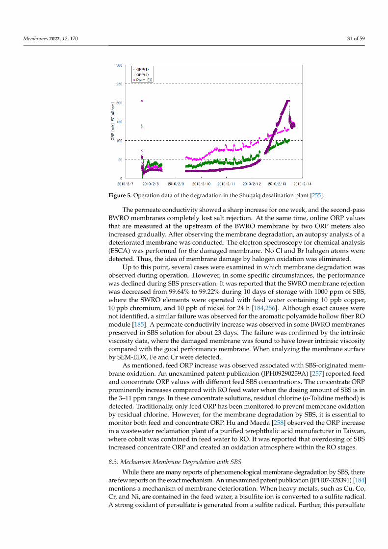
Membranes 2022, 12, 170 31 of 59Membranes 2022, 12, x FOR PEER REVIEW 32 of 60
Figure 5. Operation data of the degradation in the Shuqaiq desalination plant [255].
The permeate conductivity showed a sharp increase for one week, and the second-pass BWRO membranes completely lost salt rejection. At the same time, online ORP val-ues that are measured at the upstream of the BWRO membrane by two ORP meters also increased gradually. After observing the membrane degradation, an autopsy analysis of a deteriorated membrane was conducted. The electron spectroscopy for chemical analysis (ESCA) was performed for the damaged membrane. No Cl and Br halogen atoms were detected. Thus, the idea of membrane damage by halogen oxidation was eliminated.
Up to this point, several cases were examined in which membrane degradation was observed during operation. However, in some specific circumstances, the performance was declined during SBS preservation. It was reported that the SWRO membrane rejection was decreased from 99.64% to 99.22% during 10 days of storage with 1,000 ppm of SBS, where the SWRO elements were operated with feed water containing 10 ppb copper, 10 ppb chromium, and 10 ppb of nickel for 24 h [184,256]. Although exact causes were not identified, a similar failure was observed for the aromatic polyamide hollow fiber RO module [185]. A permeate conductivity increase was observed in some BWRO membranes preserved in SBS solution for about 23 days. The failure was confirmed by the intrinsic viscosity data, where the damaged membrane was found to have lower intrinsic viscosity compared with the good performance membrane. When analyzing the membrane surface by SEM-EDX, Fe and Cr were detected.
As mentioned, feed ORP increase was observed associated with SBS-originated membrane oxidation. An unexamined patent publication (JPH09290259A) [257] reported feed and concentrate ORP values with different feed SBS concentrations. The concentrate ORP prominently increases compared with RO feed water when the dosing amount of SBS is in the 3–11 ppm range. In these concentrate solutions, residual chlorine (o-Tolidine method) is detected. Traditionally, only feed ORP has been monitored to prevent mem-brane oxidation by residual chlorine. However, for the membrane degradation by SBS, it is essential to monitor both feed and concentrate ORP. Hu and Maeda [258] observed the ORP increase in a wastewater reclamation plant of a purified terephthalic acid manufac-turer in Taiwan, where cobalt was contained in feed water to RO. It was reported that overdosing of SBS increased concentrate ORP and created an oxidation atmosphere within the RO stages.
8.3. Mechanism Membrane Degradation with SBS While there are many reports of phenomenological membrane degradation by SBS,
there are few reports on the exact mechanism. An unexamined patent publication (JPH07-328391) [184] mentions a mechanism of membrane deterioration. When heavy metals,
Figure 5. Operation data of the degradation in the Shuqaiq desalination plant [255].
The permeate conductivity showed a sharp increase for one week, and the second-passBWRO membranes completely lost salt rejection. At the same time, online ORP valuesthat are measured at the upstream of the BWRO membrane by two ORP meters alsoincreased gradually. After observing the membrane degradation, an autopsy analysis of adeteriorated membrane was conducted. The electron spectroscopy for chemical analysis(ESCA) was performed for the damaged membrane. No Cl and Br halogen atoms weredetected. Thus, the idea of membrane damage by halogen oxidation was eliminated.
Up to this point, several cases were examined in which membrane degradation wasobserved during operation. However, in some specific circumstances, the performancewas declined during SBS preservation. It was reported that the SWRO membrane rejectionwas decreased from 99.64% to 99.22% during 10 days of storage with 1000 ppm of SBS,where the SWRO elements were operated with feed water containing 10 ppb copper,10 ppb chromium, and 10 ppb of nickel for 24 h [184,256]. Although exact causes werenot identified, a similar failure was observed for the aromatic polyamide hollow fiber ROmodule [185]. A permeate conductivity increase was observed in some BWRO membranespreserved in SBS solution for about 23 days. The failure was confirmed by the intrinsicviscosity data, where the damaged membrane was found to have lower intrinsic viscositycompared with the good performance membrane. When analyzing the membrane surfaceby SEM-EDX, Fe and Cr were detected.
As mentioned, feed ORP increase was observed associated with SBS-originated mem-brane oxidation. An unexamined patent publication (JPH09290259A) [257] reported feedand concentrate ORP values with different feed SBS concentrations. The concentrate ORPprominently increases compared with RO feed water when the dosing amount of SBS is inthe 3–11 ppm range. In these concentrate solutions, residual chlorine (o-Tolidine method) isdetected. Traditionally, only feed ORP has been monitored to prevent membrane oxidationby residual chlorine. However, for the membrane degradation by SBS, it is essential tomonitor both feed and concentrate ORP. Hu and Maeda [258] observed the ORP increasein a wastewater reclamation plant of a purified terephthalic acid manufacturer in Taiwan,where cobalt was contained in feed water to RO. It was reported that overdosing of SBSincreased concentrate ORP and created an oxidation atmosphere within the RO stages.
8.3. Mechanism Membrane Degradation with SBS
While there are many reports of phenomenological membrane degradation by SBS, thereare few reports on the exact mechanism. An unexamined patent publication (JPH07-328391) [184]mentions a mechanism of membrane deterioration. When heavy metals, such as Cu, Co,Cr, and Ni, are contained in the feed water, a bisulfite ion is converted to a sulfite radical.A strong oxidant of persulfate is generated from a sulfite radical. Further, this persulfate
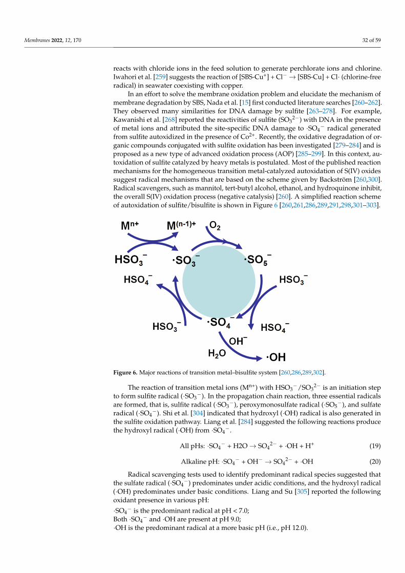
Membranes 2022, 12, 170 32 of 59
reacts with chloride ions in the feed solution to generate perchlorate ions and chlorine.Iwahori et al. [259] suggests the reaction of [SBS-Cu+] + Cl−→ [SBS-Cu] + Cl· (chlorine-freeradical) in seawater coexisting with copper.
In an effort to solve the membrane oxidation problem and elucidate the mechanism ofmembrane degradation by SBS, Nada et al. [15] first conducted literature searches [260–262].They observed many similarities for DNA damage by sulfite [263–278]. For example,Kawanishi et al. [268] reported the reactivities of sulfite (SO3
2−) with DNA in the presenceof metal ions and attributed the site-specific DNA damage to ·SO4
− radical generatedfrom sulfite autoxidized in the presence of Co2+. Recently, the oxidative degradation of or-ganic compounds conjugated with sulfite oxidation has been investigated [279–284] and isproposed as a new type of advanced oxidation process (AOP) [285–299]. In this context, au-toxidation of sulfite catalyzed by heavy metals is postulated. Most of the published reactionmechanisms for the homogeneous transition metal-catalyzed autoxidation of S(IV) oxidessuggest radical mechanisms that are based on the scheme given by Backström [260,300].Radical scavengers, such as mannitol, tert-butyl alcohol, ethanol, and hydroquinone inhibit,the overall S(IV) oxidation process (negative catalysis) [260]. A simplified reaction schemeof autoxidation of sulfite/bisulfite is shown in Figure 6 [260,261,286,289,291,298,301–303].
Membranes 2022, 12, x FOR PEER REVIEW 33 of 60
such as Cu, Co, Cr, and Ni, are contained in the feed water, a bisulfite ion is converted to a sulfite radical. A strong oxidant of persulfate is generated from a sulfite radical. Further, this persulfate reacts with chloride ions in the feed solution to generate perchlorate ions and chlorine. Iwahori et al. [259] suggests the reaction of [SBS-Cu+] + Cl− → [SBS-Cu] + Cl (chlorine-free radical) in seawater coexisting with copper.
In an effort to solve the membrane oxidation problem and elucidate the mechanism of membrane degradation by SBS, Nada et al. [15] first conducted literature searches [260–262]. They observed many similarities for DNA damage by sulfite [263–278]. For example, Kawanishi et al. [268] reported the reactivities of sulfite (SO32−) with DNA in the presence of metal ions and attributed the site-specific DNA damage to SO4− radical generated from sulfite autoxidized in the presence of Co2+. Recently, the oxidative degradation of organic compounds conjugated with sulfite oxidation has been investigated [279–284] and is pro-posed as a new type of advanced oxidation process (AOP) [285–299]. In this context, au-toxidation of sulfite catalyzed by heavy metals is postulated. Most of the published reac-tion mechanisms for the homogeneous transition metal-catalyzed autoxidation of S(IV) oxides suggest radical mechanisms that are based on the scheme given by Backström [260,300]. Radical scavengers, such as mannitol, tert-butyl alcohol, ethanol, and hydroqui-none inhibit, the overall S(IV) oxidation process (negative catalysis) [260]. A simplified reaction scheme of autoxidation of sulfite/bisulfite is shown in Figure 6. [260,261,286,289,291,298,301–303].
Figure 6. Major reactions of transition metal–bisulfite system [260,286,289,302].
The reaction of transition metal ions (Mn+) with HSO3−/SO32− is an initiation step to form sulfite radical (SO3−). In the propagation chain reaction, three essential radicals are formed, that is, sulfite radical (SO3−), peroxymonosulfate radical (SO5−), and sulfate rad-ical (SO4−). Shi et al. [304] indicated that hydroxyl (OH) radical is also generated in the sulfite oxidation pathway. Liang et al. [284] suggested the following reactions produce the hydroxyl radical (OH) from SO4−.
All pHs: SO4− + H2O → SO42− + OH + H+ (19)
Alkaline pH: SO4− + OH− → SO42− + OH (20)
Radical scavenging tests used to identify predominant radical species suggested that the sulfate radical (SO4−) predominates under acidic conditions, and the hydroxyl radical
Figure 6. Major reactions of transition metal–bisulfite system [260,286,289,302].
The reaction of transition metal ions (Mn+) with HSO3−/SO3
2− is an initiation stepto form sulfite radical (·SO3
−). In the propagation chain reaction, three essential radicalsare formed, that is, sulfite radical (·SO3
−), peroxymonosulfate radical (·SO5−), and sulfate
radical (·SO4−). Shi et al. [304] indicated that hydroxyl (·OH) radical is also generated in
the sulfite oxidation pathway. Liang et al. [284] suggested the following reactions producethe hydroxyl radical (·OH) from ·SO4
−.
All pHs: ·SO4− + H2O→ SO4
2− + ·OH + H+ (19)
Alkaline pH: ·SO4− + OH− → SO4
2− + ·OH (20)
Radical scavenging tests used to identify predominant radical species suggested thatthe sulfate radical (·SO4
−) predominates under acidic conditions, and the hydroxyl radical(·OH) predominates under basic conditions. Liang and Su [305] reported the followingoxidant presence in various pH:
·SO4− is the predominant radical at pH < 7.0;
Both ·SO4− and ·OH are present at pH 9.0;
·OH is the predominant radical at a more basic pH (i.e., pH 12.0).
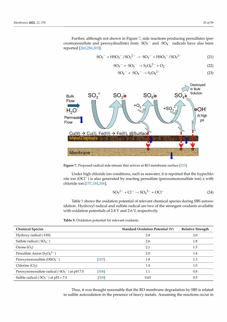
Membranes 2022, 12, 170 33 of 59
Further, although not shown in Figure 7, side reactions producing persulfates (per-oxomonosulfate and peroxydisulfate) from ·SO5
− and ·SO4− radicals have also been
reported [260,286,303].
·SO5− + HSO3
−/SO32− → ·SO3
− + HSO5−/SO5
2− (21)
·SO5− + ·SO5
− → S2O82− + O2 (22)
·SO4− + ·SO4
− → S2O82− (23)
Membranes 2022, 12, x FOR PEER REVIEW 35 of 60
Figure 7. Proposed radical side-stream that arrives at RO membrane surface [255].
8.4. Factors of Membrane Degradation with SBS Regarding deoxygenation with SBS, Matsuka et al. [197] elucidated the effect of sa-
linity, bicarbonate ion concentration, pH, temperature, cupric ion, and EDTA. Osta and Bakheet [47] pointed out that bisulfite reaction with oxygen at the Umm Lujj SWRO plant is fast, due to the following factors: (a) metal in seawater serving as catalysts; (b) high ionic strength; (c) specific pH; (d) high bicarbonate concentration; and (e) high temperature. Nagai et al. [248] indicated several factors concerned with the generation of an oxidizing agent. Kawada et al. [252,309] revealed the importance of NaCl concentration, bicarbonate ion, and pH. The controlling factors affecting membrane degradation by SBS are summa-rized in Table 10.
Table 10. Factors affecting membrane degradation by SBS.
Factors Affecting Membrane Degradation by SBS References Heavy metals [47,248,252,309] SBS concentration [248,309] Dissolved oxygen concentration [248] Feed pH [47,197,309] Bicarbonate ion concentration [47,197,309] Chloride ion concentration [248] Salinity or feed TDS [47,197] Temperature [47,197]
8.4.1. Effect of Heavy Metals Heavy metals have a critical role in the initiation step forming the SO3− radical as a
catalyst. Brandt and Eldik [260] summarize the catalytic activity of transition metal ions in the oxidation of S(IV) oxides. They reported that iron and manganese are the most ef-fective catalysts in the oxidation of S(IV) oxides in an aqueous solution. Thus, heavy met-als’ effect on the RO membrane degradation was intensively investigated. These findings are summarized in Table 11.
It appears that copper ion is the most harmful ion in seawater desalination. There are many reports that copper ion causes the SBS-originated membrane degradation. In the case of 2.5 ppb of copper ion, the ORP was the same as raw seawater (0.6V). However, for more than 10 ppb of Cu, the ORP reached over 0.85 V [248]. Kawada et al. [309] reported an ORP increase that was not observed at the copper ion concentration of 1 ppb, which is
Figure 7. Proposed radical side-stream that arrives at RO membrane surface [255].
Under high chloride ion conditions, such as seawater, it is reported that the hypochlo-rite ion (OCl−) is also generated by reacting persulfate (peroxomonosulfate ion) a withchloride ion [157,184,306].
SO52− + Cl− → SO4
2− + OCl− (24)
Table 9 shows the oxidation potential of relevant chemical species during SBS autoox-idation. Hydroxyl radical and sulfate radical are two of the strongest oxidants availablewith oxidation potentials of 2.8 V and 2.6 V, respectively.
Table 9. Oxidation potential for relevant oxidants.
Chemical Species Standard Oxidation Potential (V) Relative Strength
Hydroxy radical (·OH) 2.8 2.0
Sulfate radical (·SO4−) 2.6 1.8
Ozone (O3) 2.1 1.5
Persulfate Anion (S2O82−) 2.0 1.4
Peroxymonosulfate (HSO5−) [307] 1.8 1.3
Chlorine (Cl2) 1.4 1.0
Peroxymonosulfate radical (·SO5−) at pH 7.0 [308] 1.1 0.8
Sulfite radical (·SO3−) at pH > 7.0 [308] 0.63 0.5
Thus, it was thought reasonable that the RO membrane degradation by SBS is relatedto sulfite autoxidation in the presence of heavy metals. Assuming the reactions occur in
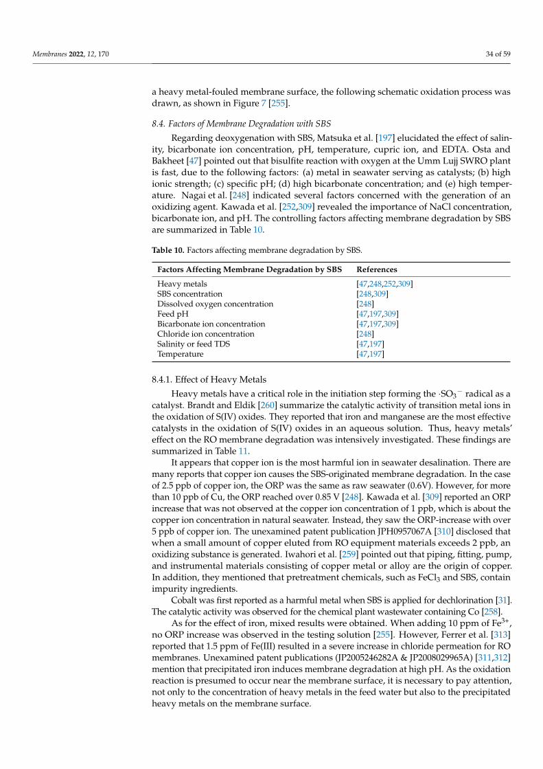
Membranes 2022, 12, 170 34 of 59
a heavy metal-fouled membrane surface, the following schematic oxidation process wasdrawn, as shown in Figure 7 [255].
8.4. Factors of Membrane Degradation with SBS
Regarding deoxygenation with SBS, Matsuka et al. [197] elucidated the effect of salin-ity, bicarbonate ion concentration, pH, temperature, cupric ion, and EDTA. Osta andBakheet [47] pointed out that bisulfite reaction with oxygen at the Umm Lujj SWRO plantis fast, due to the following factors: (a) metal in seawater serving as catalysts; (b) highionic strength; (c) specific pH; (d) high bicarbonate concentration; and (e) high temper-ature. Nagai et al. [248] indicated several factors concerned with the generation of anoxidizing agent. Kawada et al. [252,309] revealed the importance of NaCl concentration,bicarbonate ion, and pH. The controlling factors affecting membrane degradation by SBSare summarized in Table 10.
Table 10. Factors affecting membrane degradation by SBS.
Factors Affecting Membrane Degradation by SBS References
Heavy metals [47,248,252,309]SBS concentration [248,309]Dissolved oxygen concentration [248]Feed pH [47,197,309]Bicarbonate ion concentration [47,197,309]Chloride ion concentration [248]Salinity or feed TDS [47,197]Temperature [47,197]
8.4.1. Effect of Heavy Metals
Heavy metals have a critical role in the initiation step forming the ·SO3− radical as a
catalyst. Brandt and Eldik [260] summarize the catalytic activity of transition metal ions inthe oxidation of S(IV) oxides. They reported that iron and manganese are the most effectivecatalysts in the oxidation of S(IV) oxides in an aqueous solution. Thus, heavy metals’effect on the RO membrane degradation was intensively investigated. These findings aresummarized in Table 11.
It appears that copper ion is the most harmful ion in seawater desalination. There aremany reports that copper ion causes the SBS-originated membrane degradation. In the caseof 2.5 ppb of copper ion, the ORP was the same as raw seawater (0.6V). However, for morethan 10 ppb of Cu, the ORP reached over 0.85 V [248]. Kawada et al. [309] reported an ORPincrease that was not observed at the copper ion concentration of 1 ppb, which is about thecopper ion concentration in natural seawater. Instead, they saw the ORP-increase with over5 ppb of copper ion. The unexamined patent publication JPH0957067A [310] disclosed thatwhen a small amount of copper eluted from RO equipment materials exceeds 2 ppb, anoxidizing substance is generated. Iwahori et al. [259] pointed out that piping, fitting, pump,and instrumental materials consisting of copper metal or alloy are the origin of copper.In addition, they mentioned that pretreatment chemicals, such as FeCl3 and SBS, containimpurity ingredients.
Cobalt was first reported as a harmful metal when SBS is applied for dechlorination [31].The catalytic activity was observed for the chemical plant wastewater containing Co [258].
As for the effect of iron, mixed results were obtained. When adding 10 ppm of Fe3+,no ORP increase was observed in the testing solution [255]. However, Ferrer et al. [313]reported that 1.5 ppm of Fe(III) resulted in a severe increase in chloride permeation for ROmembranes. Unexamined patent publications (JP2005246282A & JP2008029965A) [311,312]mention that precipitated iron induces membrane degradation at high pH. As the oxidationreaction is presumed to occur near the membrane surface, it is necessary to pay attention,not only to the concentration of heavy metals in the feed water but also to the precipitatedheavy metals on the membrane surface.
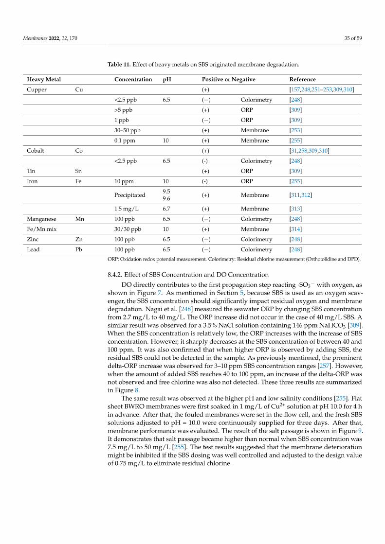
Membranes 2022, 12, 170 35 of 59
Table 11. Effect of heavy metals on SBS originated membrane degradation.
Heavy Metal Concentration pH Positive or Negative Reference
Cupper Cu (+) [157,248,251–253,309,310]
<2.5 ppb 6.5 (−) Colorimetry [248]
>5 ppb (+) ORP [309]
1 ppb (−) ORP [309]
30–50 ppb (+) Membrane [253]
0.1 ppm 10 (+) Membrane [255]
Cobalt Co (+) [31,258,309,310]
<2.5 ppb 6.5 (-) Colorimetry [248]
Tin Sn (+) ORP [309]
Iron Fe 10 ppm 10 (-) ORP [255]
Precipitated 9.59.6 (+) Membrane [311,312]
1.5 mg/L 6.7 (+) Membrane [313]
Manganese Mn 100 ppb 6.5 (−) Colorimetry [248]
Fe/Mn mix 30/30 ppb 10 (+) Membrane [314]
Zinc Zn 100 ppb 6.5 (−) Colorimetry [248]
Lead Pb 100 ppb 6.5 (−) Colorimetry [248]
ORP: Oxidation redox potential measurement. Colorimetry: Residual chlorine measurement (Orthotolidine and DPD).
8.4.2. Effect of SBS Concentration and DO Concentration
DO directly contributes to the first propagation step reacting ·SO3− with oxygen, as
shown in Figure 7. As mentioned in Section 5, because SBS is used as an oxygen scav-enger, the SBS concentration should significantly impact residual oxygen and membranedegradation. Nagai et al. [248] measured the seawater ORP by changing SBS concentrationfrom 2.7 mg/L to 40 mg/L. The ORP increase did not occur in the case of 40 mg/L SBS. Asimilar result was observed for a 3.5% NaCl solution containing 146 ppm NaHCO3 [309].When the SBS concentration is relatively low, the ORP increases with the increase of SBSconcentration. However, it sharply decreases at the SBS concentration of between 40 and100 ppm. It was also confirmed that when higher ORP is observed by adding SBS, theresidual SBS could not be detected in the sample. As previously mentioned, the prominentdelta-ORP increase was observed for 3–10 ppm SBS concentration ranges [257]. However,when the amount of added SBS reaches 40 to 100 ppm, an increase of the delta-ORP wasnot observed and free chlorine was also not detected. These three results are summarizedin Figure 8.
The same result was observed at the higher pH and low salinity conditions [255]. Flatsheet BWRO membranes were first soaked in 1 mg/L of Cu2+ solution at pH 10.0 for 4 hin advance. After that, the fouled membranes were set in the flow cell, and the fresh SBSsolutions adjusted to pH = 10.0 were continuously supplied for three days. After that,membrane performance was evaluated. The result of the salt passage is shown in Figure 9.It demonstrates that salt passage became higher than normal when SBS concentration was7.5 mg/L to 50 mg/L [255]. The test results suggested that the membrane deteriorationmight be inhibited if the SBS dosing was well controlled and adjusted to the design valueof 0.75 mg/L to eliminate residual chlorine.
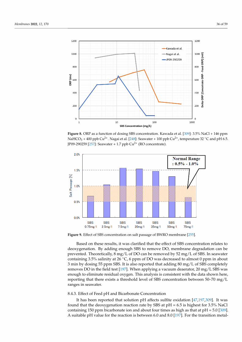
Membranes 2022, 12, 170 36 of 59
Membranes 2022, 12, x FOR PEER REVIEW 37 of 60
SBS could not be detected in the sample. As previously mentioned, the prominent delta-ORP increase was observed for 3–10 ppm SBS concentration ranges [257]. However, when the amount of added SBS reaches 40 to 100 ppm, an increase of the delta-ORP was not observed and free chlorine was also not detected. These three results are summarized in Figure 8.
Figure 8. ORP as a function of dosing SBS concentration. Kawada et al. [309]: 3.5% NaCl + 146 ppm NaHCO3 + 400 ppb Cu2+. Nagai et al. [248]: Seawater + 100 ppb Cu2+, temperature 32 °C and pH 6.5. JP09-290259 [257]: Seawater + 1.7 ppb Cu2+ (RO concentrate).
The same result was observed at the higher pH and low salinity conditions [255]. Flat sheet BWRO membranes were first soaked in 1 mg/L of Cu2+ solution at pH 10.0 for 4 h in advance. After that, the fouled membranes were set in the flow cell, and the fresh SBS solutions adjusted to pH = 10.0 were continuously supplied for three days. After that, membrane performance was evaluated. The result of the salt passage is shown in Figure 9. It demonstrates that salt passage became higher than normal when SBS concentration was 7.5 mg/L to 50 mg/L. [255]. The test results suggested that the membrane deterioration might be inhibited if the SBS dosing was well controlled and adjusted to the design value of 0.75 mg/L to eliminate residual chlorine.
Figure 9. Effect of SBS concentration on salt passage of BWRO membrane [255].
Figure 8. ORP as a function of dosing SBS concentration. Kawada et al. [309]: 3.5% NaCl + 146 ppmNaHCO3 + 400 ppb Cu2+. Nagai et al. [248]: Seawater + 100 ppb Cu2+, temperature 32 ◦C and pH 6.5.JP09-290259 [257]: Seawater + 1.7 ppb Cu2+ (RO concentrate).
Membranes 2022, 12, x FOR PEER REVIEW 37 of 60
SBS could not be detected in the sample. As previously mentioned, the prominent delta-ORP increase was observed for 3–10 ppm SBS concentration ranges [257]. However, when the amount of added SBS reaches 40 to 100 ppm, an increase of the delta-ORP was not observed and free chlorine was also not detected. These three results are summarized in Figure 8.
Figure 8. ORP as a function of dosing SBS concentration. Kawada et al. [309]: 3.5% NaCl + 146 ppm NaHCO3 + 400 ppb Cu2+. Nagai et al. [248]: Seawater + 100 ppb Cu2+, temperature 32 °C and pH 6.5. JP09-290259 [257]: Seawater + 1.7 ppb Cu2+ (RO concentrate).
The same result was observed at the higher pH and low salinity conditions [255]. Flat sheet BWRO membranes were first soaked in 1 mg/L of Cu2+ solution at pH 10.0 for 4 h in advance. After that, the fouled membranes were set in the flow cell, and the fresh SBS solutions adjusted to pH = 10.0 were continuously supplied for three days. After that, membrane performance was evaluated. The result of the salt passage is shown in Figure 9. It demonstrates that salt passage became higher than normal when SBS concentration was 7.5 mg/L to 50 mg/L. [255]. The test results suggested that the membrane deterioration might be inhibited if the SBS dosing was well controlled and adjusted to the design value of 0.75 mg/L to eliminate residual chlorine.
Figure 9. Effect of SBS concentration on salt passage of BWRO membrane [255]. Figure 9. Effect of SBS concentration on salt passage of BWRO membrane [255].
Based on these results, it was clarified that the effect of SBS concentration relates todeoxygenation. By adding enough SBS to remove DO, membrane degradation can beprevented. Theoretically, 8 mg/L of DO can be removed by 52 mg/L of SBS. In seawatercontaining 3.5% salinity at 26 ◦C, 6 ppm of DO was decreased to almost 0 ppm in about3 min by dosing 55 ppm SBS. It is also reported that adding 80 mg/L of SBS completelyremoves DO in the field test [197]. When applying a vacuum deaerator, 20 mg/L SBS wasenough to eliminate residual oxygen. This analysis is consistent with the data shown here,reporting that there exists a threshold level of SBS concentration between 50–70 mg/Lranges in seawater.
8.4.3. Effect of Feed pH and Bicarbonate Concentration
It has been reported that solution pH affects sulfite oxidation [47,197,309]. It wasfound that the deoxygenation reaction rate by SBS at pH = 6.5 is highest for 3.5% NaClcontaining 150 ppm bicarbonate ion and about four times as high as that at pH = 5.0 [309].A suitable pH value for the reaction is between 6.0 and 8.0 [197]. For the transition metal-
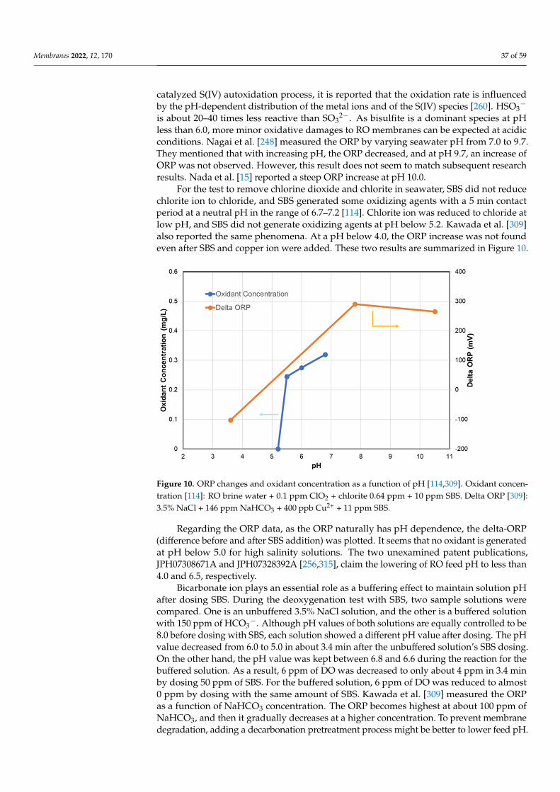
Membranes 2022, 12, 170 37 of 59
catalyzed S(IV) autoxidation process, it is reported that the oxidation rate is influencedby the pH-dependent distribution of the metal ions and of the S(IV) species [260]. HSO3
−
is about 20–40 times less reactive than SO32−. As bisulfite is a dominant species at pH
less than 6.0, more minor oxidative damages to RO membranes can be expected at acidicconditions. Nagai et al. [248] measured the ORP by varying seawater pH from 7.0 to 9.7.They mentioned that with increasing pH, the ORP decreased, and at pH 9.7, an increase ofORP was not observed. However, this result does not seem to match subsequent researchresults. Nada et al. [15] reported a steep ORP increase at pH 10.0.
For the test to remove chlorine dioxide and chlorite in seawater, SBS did not reducechlorite ion to chloride, and SBS generated some oxidizing agents with a 5 min contactperiod at a neutral pH in the range of 6.7–7.2 [114]. Chlorite ion was reduced to chloride atlow pH, and SBS did not generate oxidizing agents at pH below 5.2. Kawada et al. [309]also reported the same phenomena. At a pH below 4.0, the ORP increase was not foundeven after SBS and copper ion were added. These two results are summarized in Figure 10.
Membranes 2022, 12, x FOR PEER REVIEW 38 of 60
Based on these results, it was clarified that the effect of SBS concentration relates to deoxygenation. By adding enough SBS to remove DO, membrane degradation can be pre-vented. Theoretically, 8 mg/L of DO can be removed by 52 mg/L of SBS. In seawater con-taining 3.5% salinity at 26 °C, 6 ppm of DO was decreased to almost 0 ppm in about 3 min by dosing 55 ppm SBS. It is also reported that adding 80 mg/L of SBS completely removes DO in the field test [197]. When applying a vacuum deaerator, 20 mg/L SBS was enough to eliminate residual oxygen. This analysis is consistent with the data shown here, report-ing that there exists a threshold level of SBS concentration between 50–70 mg/L ranges in seawater.
8.4.3. Effect of Feed pH and Bicarbonate Concentration It has been reported that solution pH affects sulfite oxidation [47,197,309]. It was
found that the deoxygenation reaction rate by SBS at pH = 6.5 is highest for 3.5% NaCl containing 150 ppm bicarbonate ion and about four times as high as that at pH = 5.0 [309]. A suitable pH value for the reaction is between 6.0 and 8.0 [197]. For the transition metal-catalyzed S(IV) autoxidation process, it is reported that the oxidation rate is influenced by the pH-dependent distribution of the metal ions and of the S(IV) species [260]. HSO3− is about 20–40 times less reactive than SO32−. As bisulfite is a dominant species at pH less than 6.0, more minor oxidative damages to RO membranes can be expected at acidic con-ditions. Nagai et al. [248] measured the ORP by varying seawater pH from 7.0 to 9.7. They mentioned that with increasing pH, the ORP decreased, and at pH 9.7, an increase of ORP was not observed. However, this result does not seem to match subsequent research re-sults. Nada et al. [15] reported a steep ORP increase at pH 10.0.
For the test to remove chlorine dioxide and chlorite in seawater, SBS did not reduce chlorite ion to chloride, and SBS generated some oxidizing agents with a 5 min contact period at a neutral pH in the range of 6.7–7.2 [114]. Chlorite ion was reduced to chloride at low pH, and SBS did not generate oxidizing agents at pH below 5.2. Kawada et al. [309] also reported the same phenomena. At a pH below 4.0, the ORP increase was not found even after SBS and copper ion were added. These two results are summarized in Figure 10.
Figure 10. ORP changes and oxidant concentration as a function of pH [114,309]. Oxidant concen-tration [114]: RO brine water + 0.1 ppm ClO2 + chlorite 0.64 ppm + 10 ppm SBS. Delta ORP [309]: 3.5% NaCl + 146 ppm NaHCO3 + 400 ppb Cu2+ + 11 ppm SBS.
Figure 10. ORP changes and oxidant concentration as a function of pH [114,309]. Oxidant concen-tration [114]: RO brine water + 0.1 ppm ClO2 + chlorite 0.64 ppm + 10 ppm SBS. Delta ORP [309]:3.5% NaCl + 146 ppm NaHCO3 + 400 ppb Cu2+ + 11 ppm SBS.
Regarding the ORP data, as the ORP naturally has pH dependence, the delta-ORP(difference before and after SBS addition) was plotted. It seems that no oxidant is generatedat pH below 5.0 for high salinity solutions. The two unexamined patent publications,JPH07308671A and JPH07328392A [256,315], claim the lowering of RO feed pH to less than4.0 and 6.5, respectively.
Bicarbonate ion plays an essential role as a buffering effect to maintain solution pHafter dosing SBS. During the deoxygenation test with SBS, two sample solutions werecompared. One is an unbuffered 3.5% NaCl solution, and the other is a buffered solutionwith 150 ppm of HCO3
−. Although pH values of both solutions are equally controlled to be8.0 before dosing with SBS, each solution showed a different pH value after dosing. The pHvalue decreased from 6.0 to 5.0 in about 3.4 min after the unbuffered solution’s SBS dosing.On the other hand, the pH value was kept between 6.8 and 6.6 during the reaction for thebuffered solution. As a result, 6 ppm of DO was decreased to only about 4 ppm in 3.4 minby dosing 50 ppm of SBS. For the buffered solution, 6 ppm of DO was reduced to almost0 ppm by dosing with the same amount of SBS. Kawada et al. [309] measured the ORPas a function of NaHCO3 concentration. The ORP becomes highest at about 100 ppm ofNaHCO3, and then it gradually decreases at a higher concentration. To prevent membranedegradation, adding a decarbonation pretreatment process might be better to lower feed pH.
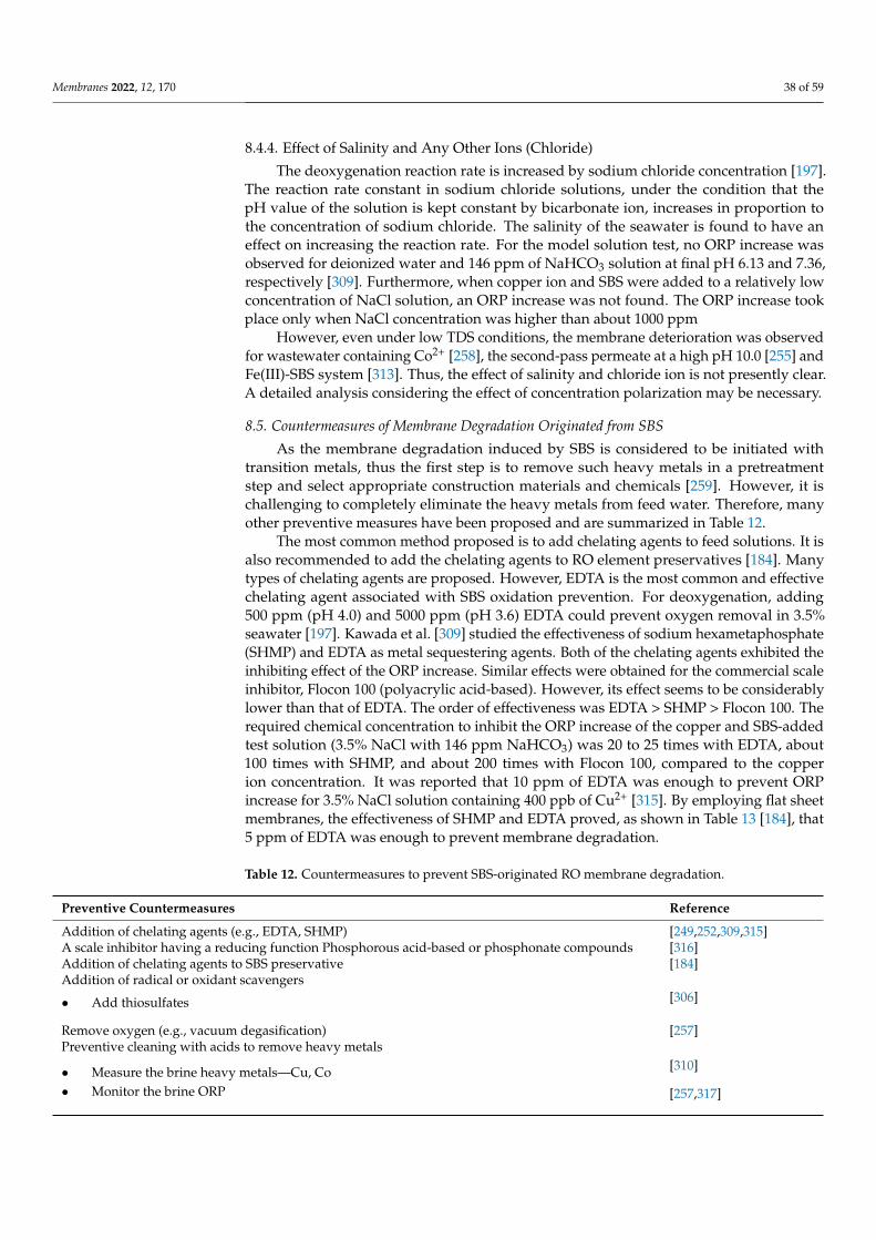
Membranes 2022, 12, 170 38 of 59
8.4.4. Effect of Salinity and Any Other Ions (Chloride)
The deoxygenation reaction rate is increased by sodium chloride concentration [197].The reaction rate constant in sodium chloride solutions, under the condition that thepH value of the solution is kept constant by bicarbonate ion, increases in proportion tothe concentration of sodium chloride. The salinity of the seawater is found to have aneffect on increasing the reaction rate. For the model solution test, no ORP increase wasobserved for deionized water and 146 ppm of NaHCO3 solution at final pH 6.13 and 7.36,respectively [309]. Furthermore, when copper ion and SBS were added to a relatively lowconcentration of NaCl solution, an ORP increase was not found. The ORP increase tookplace only when NaCl concentration was higher than about 1000 ppm
However, even under low TDS conditions, the membrane deterioration was observedfor wastewater containing Co2+ [258], the second-pass permeate at a high pH 10.0 [255] andFe(III)-SBS system [313]. Thus, the effect of salinity and chloride ion is not presently clear.A detailed analysis considering the effect of concentration polarization may be necessary.
8.5. Countermeasures of Membrane Degradation Originated from SBS
As the membrane degradation induced by SBS is considered to be initiated withtransition metals, thus the first step is to remove such heavy metals in a pretreatmentstep and select appropriate construction materials and chemicals [259]. However, it ischallenging to completely eliminate the heavy metals from feed water. Therefore, manyother preventive measures have been proposed and are summarized in Table 12.
The most common method proposed is to add chelating agents to feed solutions. It isalso recommended to add the chelating agents to RO element preservatives [184]. Manytypes of chelating agents are proposed. However, EDTA is the most common and effectivechelating agent associated with SBS oxidation prevention. For deoxygenation, adding500 ppm (pH 4.0) and 5000 ppm (pH 3.6) EDTA could prevent oxygen removal in 3.5%seawater [197]. Kawada et al. [309] studied the effectiveness of sodium hexametaphosphate(SHMP) and EDTA as metal sequestering agents. Both of the chelating agents exhibited theinhibiting effect of the ORP increase. Similar effects were obtained for the commercial scaleinhibitor, Flocon 100 (polyacrylic acid-based). However, its effect seems to be considerablylower than that of EDTA. The order of effectiveness was EDTA > SHMP > Flocon 100. Therequired chemical concentration to inhibit the ORP increase of the copper and SBS-addedtest solution (3.5% NaCl with 146 ppm NaHCO3) was 20 to 25 times with EDTA, about100 times with SHMP, and about 200 times with Flocon 100, compared to the copperion concentration. It was reported that 10 ppm of EDTA was enough to prevent ORPincrease for 3.5% NaCl solution containing 400 ppb of Cu2+ [315]. By employing flat sheetmembranes, the effectiveness of SHMP and EDTA proved, as shown in Table 13 [184], that5 ppm of EDTA was enough to prevent membrane degradation.
Table 12. Countermeasures to prevent SBS-originated RO membrane degradation.
Preventive Countermeasures Reference
Addition of chelating agents (e.g., EDTA, SHMP) [249,252,309,315]A scale inhibitor having a reducing function Phosphorous acid-based or phosphonate compounds [316]Addition of chelating agents to SBS preservative [184]Addition of radical or oxidant scavengers
• Add thiosulfates [306]
Remove oxygen (e.g., vacuum degasification) [257]Preventive cleaning with acids to remove heavy metals
• Measure the brine heavy metals—Cu, Co [310]
• Monitor the brine ORP [257,317]
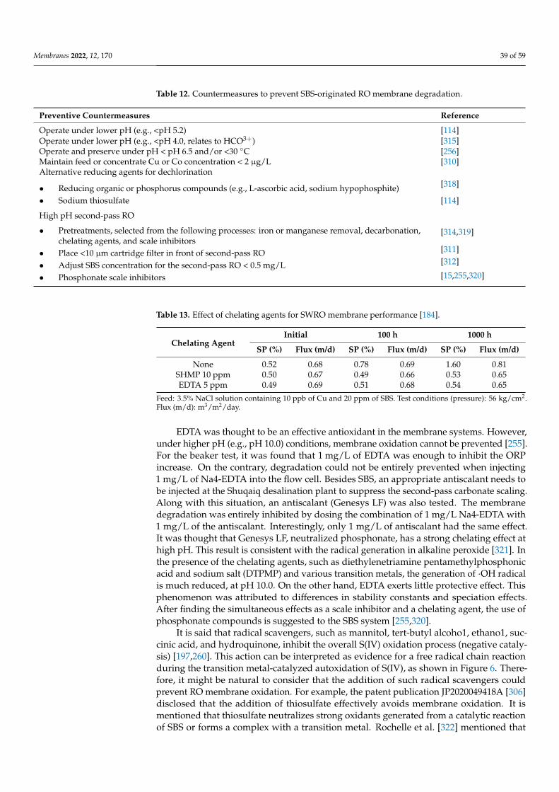
Membranes 2022, 12, 170 39 of 59
Table 12. Countermeasures to prevent SBS-originated RO membrane degradation.
Preventive Countermeasures Reference
Operate under lower pH (e.g., <pH 5.2) [114]Operate under lower pH (e.g., <pH 4.0, relates to HCO3+) [315]Operate and preserve under pH < pH 6.5 and/or <30 ◦C [256]Maintain feed or concentrate Cu or Co concentration < 2 µg/L [310]Alternative reducing agents for dechlorination
• Reducing organic or phosphorus compounds (e.g., L-ascorbic acid, sodium hypophosphite) [318]
• Sodium thiosulfate [114]
High pH second-pass RO
• Pretreatments, selected from the following processes: iron or manganese removal, decarbonation,chelating agents, and scale inhibitors
[314,319]
• Place <10 µm cartridge filter in front of second-pass RO [311]
• Adjust SBS concentration for the second-pass RO < 0.5 mg/L [312]
• Phosphonate scale inhibitors [15,255,320]
Table 13. Effect of chelating agents for SWRO membrane performance [184].
Chelating AgentInitial 100 h 1000 h
SP (%) Flux (m/d) SP (%) Flux (m/d) SP (%) Flux (m/d)
None 0.52 0.68 0.78 0.69 1.60 0.81SHMP 10 ppm 0.50 0.67 0.49 0.66 0.53 0.65EDTA 5 ppm 0.49 0.69 0.51 0.68 0.54 0.65
Feed: 3.5% NaCl solution containing 10 ppb of Cu and 20 ppm of SBS. Test conditions (pressure): 56 kg/cm2.Flux (m/d): m3/m2/day.
EDTA was thought to be an effective antioxidant in the membrane systems. However,under higher pH (e.g., pH 10.0) conditions, membrane oxidation cannot be prevented [255].For the beaker test, it was found that 1 mg/L of EDTA was enough to inhibit the ORPincrease. On the contrary, degradation could not be entirely prevented when injecting1 mg/L of Na4-EDTA into the flow cell. Besides SBS, an appropriate antiscalant needs tobe injected at the Shuqaiq desalination plant to suppress the second-pass carbonate scaling.Along with this situation, an antiscalant (Genesys LF) was also tested. The membranedegradation was entirely inhibited by dosing the combination of 1 mg/L Na4-EDTA with1 mg/L of the antiscalant. Interestingly, only 1 mg/L of antiscalant had the same effect.It was thought that Genesys LF, neutralized phosphonate, has a strong chelating effect athigh pH. This result is consistent with the radical generation in alkaline peroxide [321]. Inthe presence of the chelating agents, such as diethylenetriamine pentamethylphosphonicacid and sodium salt (DTPMP) and various transition metals, the generation of ·OH radicalis much reduced, at pH 10.0. On the other hand, EDTA exerts little protective effect. Thisphenomenon was attributed to differences in stability constants and speciation effects.After finding the simultaneous effects as a scale inhibitor and a chelating agent, the use ofphosphonate compounds is suggested to the SBS system [255,320].
It is said that radical scavengers, such as mannitol, tert-butyl alcoho1, ethano1, suc-cinic acid, and hydroquinone, inhibit the overall S(IV) oxidation process (negative cataly-sis) [197,260]. This action can be interpreted as evidence for a free radical chain reactionduring the transition metal-catalyzed autoxidation of S(IV), as shown in Figure 6. There-fore, it might be natural to consider that the addition of such radical scavengers couldprevent RO membrane oxidation. For example, the patent publication JP2020049418A [306]disclosed that the addition of thiosulfate effectively avoids membrane oxidation. It ismentioned that thiosulfate neutralizes strong oxidants generated from a catalytic reactionof SBS or forms a complex with a transition metal. Rochelle et al. [322] mentioned that
Membranes 2022, 12, 170 40 of 59
thiosulfate appears to function as a free radical scavenger rather than a complexer of S(IV)(sulfite plus bisulfite) or metal ions. However, using thiosulfates as a dechlorinating agentmight be straightforward and simpler, as mentioned by Tanaka et al. [114].
The next countermeasure is to conduct preventive CIP. This approach first needsto detect a sign of oxidation. For this purpose, two methods are proposed. The meth-ods are to monitor the heavy metal concentration, e.g., Cu and Co, or the ORP in thebrine [257,310,317]. It is disclosed that membrane degradation can be prevented by setting300 mv of ORP as the control value and conducting the timely CIP with citric acid [317].Changing the operational conditions, such as pH and temperature, might be an alternativeapproach. As it has been reported that neither oxidant nor ORP increase was observed atlower pH, operating an RO system with lower pH can be considered an option for systemdesign [114,256,315]. SBS has been widely used for dechlorination in RO systems due toits reliability and economic aspects. However, from the point of preventive membranedegradation, alternative reducing agents were proposed. Tanaka et al. [114] found thatsodium thiosulfate does not form oxidizing agents. Thus, using sodium thiosulfate mightbe an option for dechlorination. Other types of reducing agents were also proposed, suchas reducing organic or phosphorus compounds (e.g., L-ascorbic acid, sodium hypophos-phite) [318].
As mentioned previously, unexpected membrane oxidation was encountered in theShuqaiq seawater desalination plant, where the second-pass BWRO was operated atpH 10.0 to increase boron rejection. Usually, a dechlorination step is not necessary forthe second-pass RO. However, when using the cellulose acetate SWRO in the first pass andapplying intermittent chlorination, the dechlorination process becomes necessary for thesecond-pass BWRO. Originally, heavy metal fouling was not anticipated for the second pass.However, heavy inorganic foulants were detected on the membrane surface [255]. Thisissue may come from the following two reasons. First of all, residual soluble heavy metalions at lower pH are precipitated at high pH conditions. Those precipitated or colloidalmetals cannot be removed, as many second-pass RO units are not equipped with a cartridgefilter [255] in front of the BWRO. Several patents were filed [311,312,314,319,320] to addressthose specific issues at high pH conditions. The US open patent (US 2004/0050793 A1) [314]indicated the importance of removing bicarbonate ion in the pretreatment steps in additionto Fe and Mn. An unexamined patent publication (JP2005246282A) [311] claims that the feedwater is filtered with a cartridge filter having a pore size of ≤10 µm (preferably ≤ 5 µm) toremove heavy metals.
9. SBS Acts as a Trigger of Biofouling
Once before, Flemming et al. [323] referred to biofouling as the Achilles heel of mem-brane processes. After that, there has been a lot of progress in preventing biofouling, e.g.,developing low fouling RO membranes/elements, utilizing LP membranes as pretreatment,non-oxidative biocides, monitoring techniques, and so on. However, biofouling continuesto be one of the significant obstacles to achieving steady RO operations. Many reviewarticles have reported how to tackle unresolved issues [36,216,324–334].
Biofouling is a very complex membrane phenomenon. Thus, one cannot attributea single factor to a cause of a biofouling initiator. However, chlorination–dechlorinationhas been raised as one of the potential causes of enhancing biofouling. As described inSection 3, continuous chlorination–dechlorination has been implemented in RO feed watersas a part of pretreatment, such as open-intake surface seawater. It is reported that afterdechlorination with SBS, bacterial activity increased, resulting in an increase in biofoul-ing [335]. Sometimes this phenomenon is referred to as “aftergrowth” [43,57,104,336,337].Because chlorination does not sterilize the seawater, the surviving bacteria can grow quickly(aftergrowth), resulting in biofouling. Kimura et al. [228] measured in situ viable bacteriacounts in an SWRO plant in Japan, where continuous chlorination–dechlorination (SBS)was applied. Viable cells were rarely detected from the seawater samples in the presenceof chlorine. However, once adding SBS, bacteria drastically increased, especially before
Membranes 2022, 12, 170 41 of 59
the RO element and its brine. Other biofouling indices, ATP, HPC, and modified biofilmformation rate (mBFR) values were also increased after the SBS addition [338,339]. Thefollowing factors have explained the aftergrowth:
• Surviving bacterial quickly grow under no chlorine conditions and no competi-tion [104,340].
• Chlorine oxidizes NOM/humic substances, and assimilable organic carbon (AOC) isformed that can be considered as nutrients for surviving bacteria [104].
• Non-viable microorganisms following chlorination act as a nutrient source [216,341].• Produce extracellular polymeric substances (EPS) as a defense mechanism when
bacteria are exposed to chlorine [216,339].
Under the hypothesis that chlorine degrades organics in the seawater feed to producenutrients (AOCs), Moch et al. [43] proposed to operate plants without chlorination. Thesekinds of new disinfection methods, e.g., intermittent chlorination and chloramination, wereproposed and have been commonly implemented [43,342–347]. Hamida and Moch [342]reported that by eliminating the continuous addition of chlorine to seawater feed streams,biofouling had been contained, and plant availability has been maintained at over 90% in tenplants located in the Arabian Gulf, the Indian Ocean, and the Caribbean Sea. Furthermore,there have been reports that intermittent chlorination effectively prevents biofouling tobrackish RO (BWRO) plants [343]. As a result, continuous chlorination has become lesscommon, and intermittent chlorination–dechlorination appears to be more frequentlyapplied to RO, especially seawater desalination [347].
In the above phenomena for aftergrowth, the roles of SBS have received insufficientattention. However, in some cases, it was observed that high doses of SBS were notproviding improvements in the SWRO operation. But instead, the opposite of what wasexpected was observed [348]. Then, after fundamental analysis, Ito et al. [339] speculatedthat SBS alone could also trigger biofouling. In terms of such a negative impact of SBS onRO elements, the following factors were postulated:
• Creating an anaerobic environment to enhance anaerobic bacterial growth, such assulfate-reducing bacteria (SRB);
• SBS enhance some types of bacteria as food, such as sulfur-oxidizing bacteria;• SBS increase AOC due to organic oxidation.
First of all, it is said that excessive SBS dosing during dechlorination consumes someof DO and creates an anaerobic environment that increases the potential for increasedanaerobic biological growth. Byrne [75] stressed an adverse effect of SBS that is responsiblefor heavy slime formations. A definitive symptom of this is the sulfur dioxide, rotten-eggsmell noted when membrane vessels are opened. During the commissioning of the PointLisas SWRO plant in Trinidad and Tobago, the typical black color and slight stench weredetected; the sulfur scent was also observed during CIPs. Hence, it was speculated that thedechlorination step using SBS is a source of biofouling [349]. However, additional factorshave to be considered from the following points: DO level after SBS dosing and whetheranaerobic feedwater is a friend or foe.
Typically surface seawater contains 5–8 ppm of DO depending on salinity and temper-ature. To eliminate such a level of DO, at least 32–52 mg/L of additional SBS must be dosedto the feed water. In actual desalination plants, the dosing amount of SBS is much lessthan those numbers. Thus, the bulk feed water contains some oxygen and is still in aerobiccondition. However, it is well known that when a biofilm forms, anaerobic conditions existat the base of the biofilm [350]. When the SWRO plant in Santa Barbara, Curacao, encoun-tered a biofouling problem and found SRB during the element autopsy, Dorival et al. [62]postulated that facultative bacteria in the anaerobic regions begin metabolizing bisulfite.
Another issue is whether anaerobic feed water is a friend or foe for RO plant operations.There are reports that anaerobic groundwater NF/RO plants have operated well withoutprominent biofouling [199–202,234,235,351]. In the case of the Ras Abjajur brackish watertreatment plant in Bahrain, after solving initial operational difficulties, e.g., biofouling in
Membranes 2022, 12, 170 42 of 59
an antiscalant tank, the plant operated smoothly [234,235]. The same successful operationwas reported in NF plants in the Netherlands. Beyer et al. [202] mentioned that whencompared to aerobic NF and RO systems (e.g., aerated groundwaters or surface waters), theoperation and performance of the anaerobic installations (with minimal pretreatment) couldbe described as very stable. This phenomenon is explained by the higher growth rates andyields associated with aerobic growth versus anaerobic growth. Aerobic growth is limitedin the absence of oxygen because these microorganisms cannot metabolize biodegradableorganic material (BOM) [351]. Relating to SBS overdosing, some insight can be obtainedfrom the following case. As mentioned, as the PEC-1000 is less tolerant to DO, the DO hasto be removed. By adding 80 ppm of SBS, the deoxygenation is completed. Under thiscondition, a pilot with more than 7000 h was reported successful without any anaerobicbacteria fouling [196]. As for the actual SWRO plant operation in the Gulf, the plantencountered biofouling with SRB after two years of operation. However, it was reportedthat 0.1% benzalkonium chloride was able to remove the hydrogen sulfide smell [220].When reviewing data, even though SBS overdosing causes biofouling with anaerobicbacterial, e.g., SRB, anaerobic bacteria growth itself might be managed by proper CIP.
The following discussion points out that SBS enhances some types of bacteria growth,such as sulfur-oxidizing bacterial (SOB) and SRB under aerobic or anaerobic environments,respectively. It is known that certain types of anaerobic bacteria obtain energy from thedisproportionation of inorganic sulfur, such as thiosulfate or sulfite [352]. Adding SBS to abrackish subsurface water transport pipeline increases the sulfur-disproportionating bacte-ria (SDB) and Desulfocapsa together with the SRB [353]. As for the RO plants, Ito et al. [339]elucidated the effect of SBS on the biofouling potential of feed seawater by conductingmBFR measurements. During a pilot test, no chemical was added to surface seawaterwith UF pretreatment in one skid. For another skid, 1 ppm of SBS was continuouslyinjected into the feed seawater. It was demonstrated that a small amount of SBS couldstimulate microorganisms and increase the mBFR value to 60 pg-ATP/cm2/day, which isabout twice higher than that of a no-chemical dosing operation 29 pg-ATP/cm2/day. Inanother approach, assuming that SBS might be a sulfur source for microorganisms, an aprA(adenosine-5-phosphosulfate reductase) gene clone library was constructed, which encodesthe key enzyme involved in both sulfate reduction and sulfur oxidation processes [354]. InRO supply water with chlorination-dechlorination, specific aprA sequences were predomi-nant among the diversities found for respective supply water, indicating that the selectionfor bacteria involving in sulfur metabolism would have been completed.
Furthermore, from an actual SWRO plant and pilot trials, a higher concentrationof sulfur (S) was detected from membrane foulants by ICP analysis [338,355]. Thus, theauthors suspected that a higher concentration of S in the foulants could be attributed tocontinuous SBS dosing before the SWRO train. Based on these analyses and observations,it might be reasonable to consider that the overdosing of SBS induces biofouling.
Kimura et al. [228] first reported sulfur-oxidizing bacteria (SOB) as a cause of biofoul-ing in the SWRO plant. In this plant, the excess amount of SBS was added to completelyremove the residual free chlorine. The consumption of SBS at an RO portion increasedduring plant operation, and the concentration of SBS in the brine reached almost zeroeven though the SBS concentration was raised. They attribute this phenomenon to theexistence of particular sulfur-oxidizing bacteria (SOB) that can utilize bisulfite or sulfite asa sole energy source. It was also found that several bacteria in the brine were grown in adefined inorganic medium with the intermittent addition of SBS. The three isolated SOBswere Thiobacillus-like and facultatively autotrophic bacteria that are similar to the mostgeneral SOB in the sea. The same result was reported by Takeuchi et al. [356]. It was foundthat SOB was dominant in RO feed water after SBS dosing using denaturing gradient gelelectrophoresis (DGGE) and sequencing technique. SOB uses SBS as a sole energy source inRO desalination plants. Thus excess SBS dosing caused a rapid growth of SOB.
The last issue about an SBS role triggering biofouling is the possibility of increasing thefeed water’s assimilable organic carbon (AOC). As mentioned in Section 8, strong oxidants
Membranes 2022, 12, 170 43 of 59
are generated from SBS and decompose organic compounds under certain conditions. Ananomalous TOC increase was first observed in an ultrapure water (UPW) production [357].The primary UPW system consists of a two-bed, three-tower pure water system (2B3T),RO, a mixed bed ion exchange (MB), and a vacuum degasifier. SBS was added to eliminateresidual chlorine so that the residual sodium hypochlorite added to a media filter wouldnot flow into the 2B3T.
When the operation was started, the 2B3T outlet conductivity was maintained for 24 h,as designed. On the other hand, TOC began to increase from about 8 h after starting watersupply following to regenerating the ion exchange resins. The TOC concentration of theentire system rose as well. When SBS injection was stopped, the TOC did not increase, andthe TOC concentration of the whole system was stabilized. More than 100 ppb of TOCdifference was observed at the outlet of the anion tower between the SBS addition and a noaddition case.
In the SWRO area, Weinrich et al. [358–360] observed the AOC increase after SBS dos-ing at the Tampa Bay seawater desalination plant (TBSDP). It has been accepted that AOCcan be used as a good indicator of RO biofouling. In TBSDP, seawater was pretreated withapproximately 0.5–1.1 mg/L as the Cl2 of chlorine dioxide at first, and then sulfuric acid,hypochlorite, and ferric chloride were injected. After a conventional coagulation–media fil-tration, diatomaceous earth (DE) filters and cartridge filters were placed prior to the SWROdesalination membranes. AOC was generally below detection (<10 µg/L) after DE filtra-tion. However, after the cartridge filter and dosing SBS, AOC increased to 97 ± 19 µg/Lin September and 23 ± 1 µg/L in October 2012. Records indicating higher SBS doses inOctober and November coincided with the periods in which differential pressure increased.Martorell et al. [79] reported the unusually high ORP values within the feed to the ROtrains with no free chlorine concentration detected and overdosing SBS (20 ppm) in TBSDP.
Another anomalous DOC increase was observed in the large desalination plant locatedon the Red Sea coast in Saudi Arabia. Khan et al. [361] characterized the TOC/DOC invarious pretreatment steps. In this plant, SWRO membranes were also exposed to chlorine(0.25–0.30 mg/L) by stopping SBS dosing (1.5–2.5 mg/L) in the feed stream for 1 h afterevery seven hours of operation. When conducting the liquid chromatography—organiccarbon detection (LC-OCD) analysis, TOC/DOC contents increased after the SBS dosingsample. LC-OCD chromatogram confirmed an increase of the signal in the region assignedto medium to lower molecular weight organics. The increment in medium to lowermolecular weight organics was also observed in the second sampling event. However,the authors suspected that the cartridge filter was in or near the saturation state and thusstarted leaching organics. Another possible route to increase AOC is reactions betweenSBS and DBPs. Yang et al. [362] suggested that the concentrations of THMs and haloaceticacids (HAAs) in the UF effluent slightly decreased by 9.0% and 3.7%, respectively, after thefollowing addition of SBS, which might be attributed to the reaction between sulfite andDBPs in which some DBPs could be destroyed by reaction with sulfite.
To minimize the risk of biofouling triggered by SBS, controlling residual SBS concen-tration is of importance. There have been reports that implementing this practice couldsolve the biofouling problem. Hirai et al. [356,363] evaluated the effect of residual SBSon biofouling at an SWRO demonstration plant in Dukhan, Qatar. They expressed theresidual SBS concentrations as the residual chlorine. The differential pressure demonstrateda decreasing trend when the SBS residue was decreased to a value equivalent to 0.1 mg/Lchlorine (0.15 mg/L SBS). When the residual SBS was adjusted to the equivalent value of0.2 mg/L (0.3 mg/L SBS) for safety, the change of differential pressure almost disappeared.Byrne [52] suggested maintaining a residual sulfite concentration greater than zero butless than 2 mg/L as SBS. As mentioned, the Santa Barbara seawater desalination plant inCuracao experienced heavy biofouling. After the SBS addition program was modified toreduce the excess, the rate of DP increase was immediately affected [62].
Up to this point, three possibilities demonstrating that SBS enhances biological growthand biofouling in the RO process were discussed. However, as Kurihara et al. [364] indi-
Membranes 2022, 12, 170 44 of 59
cated, no data show direct evidence and quantitative impact of chlorination–dechlorinationon SWRO biofouling. Thus, the quantitative influence and mechanisms of chemical addi-tives on biofouling need to be clarified.
10. Conclusions
RO is now ubiquitous in water treatment and has been used for various applications.Innovative membrane development was a key to realizing commercial-scale RO plants.However, to be commercially successful in RO, accumulating a lot of additional scienceand technological developments was necessary. In that sense, RO is considered to bea highly integrated system consisting of a series of unit processes: (1) intake system,(2) pretreatment, (3) RO system, (4) post-treatment, and (5) effluent treatment. In each step,a variety of chemicals are used. In this review, the roles of sulfites as one of the essentialchemicals are attempted to be summarized.
As for the established usages of SBS, such as dechlorination, shock treatment, deoxy-genation, and preservation, the author strived to clarify the historical background and washappy to touch on some historical milestones, including the Coalinga BWRO plant, polyamidehollow fiber RO, PEC-1000 polyether RO membranes, dechlorination, and shock treatment.
Although sulfites are essential chemicals in RO, they have some adverse effects on ROmembranes and processes. In particular, the RO membrane oxidation catalyzed by heavymetals and a trigger of biofouling are critical issues to achieve stable operations. This reviewshed light on the mechanism of membrane oxidation and triggering biofouling by sulfites.Generating strong oxidants, such as ·SO4
− and ·OH radicals, in the presence of oxygenand heavy metals was identified as one of the root causes of membrane oxidation andtriggering biofouling. The generated oxidants attack RO membranes directly or decomposefeed DOC, which results in increasing AOC concentration. One of the measures to preventsuch problems is rigorously monitoring the residual SBS concentration and minimizingthe SBS dosing. However, at this moment, directly measuring SBS concentration is rarelyimplemented in actual plants. Thus, it may be necessary to monitor the concentration withan SBS monitor in the future.
Odor is another concern from the point of occupational safety and health when usingSBS. In that sense, odorless chemicals have been developed to replace SBS as a preservative.As the chemical-free desalination process has been investigated, the roles of SBS might beshortly changed.
Finally, if the author could fill one piece of the integrated RO technology jigsaw puzzle,this author would be unexpectedly happy.
Funding: This research received no external funding.
Institutional Review Board Statement: Not applicable.
Informed Consent Statement: Not applicable.
Acknowledgments: This review article is motivated by the author’s experience in solving anomalousmembrane degradation by SBS. At that time, many people supported solving the problem. Theauthor would like to gratefully acknowledge the technical advice of the late Terry Marsh. In addition,the author would like to thank Yoshiaki Ito for proposing and completing challenging experiments.The author is also grateful to Peter Sehn and Steve Jons for their assistance in data analysis andnumerous discussions about the oxidation mechanism. Finally, the author would like to thank TonyFuhrman for carefully reading the manuscript and valuable comments.
Conflicts of Interest: The author declares no conflict of interest. This review article represents theauthor’s personal opinion and does not necessarily reflect the views or opinions of LG Chem and LGWater Solutions.
Membranes 2022, 12, 170 45 of 59
Abbreviations
2B3T Two-bed, three-tower pure water systemAC Activated carbonAOC Assimilable organic carbonAOP Advanced oxidation processATP Adenosine triphosphateBOM Biodegradable organic materialBR Bureau of ReclamationBWRO Brakish water reverse osmosisCA Cellulose acetateCEB Chemical-enhanced backwashCF Cartridge filterCIP Cleaning in placeCMIT 5-Chloro-2-methyl-4-isothiazolin-3-oneCOD Chemical oxygen demandCTA Cellulose triacetateDBNPA 2,2-Dibromo-3-nitrilopropionamideDBP Disinfection by-productDNA Deoxyribonucleic AcidDO Dissolved oxygenDOC Dissolved organic carbonDP Differential pressureDPD N,N-diethyl-p-phenylenediamineDTPMP Diethylenetriamine pentamethylphosphonic acidED ElectrodialysisEDTA Ethylenediaminetetraacetic acidEDX Energy dispersive X-ray spectroscopyEPR Electron paramagnetic resonanceEPS Extracellular polymeric substancesESCA Electron spectroscopy for chemical analysisESR Electron spin resonanceFAC Free available chlorineHAA Haloacetic acidHPC Heterotrophic plate countICI Intermittent chlorine injectionIEX Ion exchangeIMS Integrated membrane systemLC-OCD Liquid chromatography—organic carbon detectionLP Low pressuremBFR Modified Biofilm Formation RateMC Maintenance CleaningMC1 Maintenance Cleaning with 200 ppm NaOCl solutionMF MicrofiltrationMIT 2-Methyl-4-isothiazolin-3-oneMSF Multi-stage flash evaporationNF NanofiltrationNOM Natural organic matterO&M Operation and maintenanceOIT 2-Octyl-2H-isothiazol-3-oneORP Oxidation–reduction potentialPVDF Polyvinylidene fluoride
Membranes 2022, 12, 170 46 of 59
RO Reverse osmosisSBS Sodium bisulfiteSDGs Sustainable development goalsSDI Silt density indexSEM Scanning electron microscopySHMP Sodium hexametaphosphateSMBS Sodium metabisulfiteSOB Sulfur-oxidizing bacteriaSRB Sulfate-reducing bacteriaSWCC Saline Water Conversion CorporationSWRO Seawater reverse osmosisTDS Total dissolved solidsTFC Thin-film compositeTFN Thin-film nanocompositeTHM TrihalomethaneTOC Total organic carbonUF UltrafiltrationUPW Ultra-pure waterWAC Weak acid cationXPS X-ray photoelectron spectroscopy
References1. Koros, W.J.; Ma, Y.H.; Shimidzu, T. Terminology for membranes and membrane processes (IUPAC Recommendations 1996). Pure
Appl. Chem. 1996, 68, 1479–1489. [CrossRef]2. United Nations Sustainable Development. Water and Sanitation–United Nations Sustainable Development. 2016. Available
online: https://www.un.org/sustainabledevelopment/water-and-sanitation/ (accessed on 8 July 2021).3. Van der Bruggen, B. Sustainable implementation of innovative technologies for water purification. Nat. Rev. Chem. 2021, 5,
217–218. [CrossRef]4. Lange, K.E. The Big Idea Get the Salt Out. In National Geographic. A Special issue. Water–Our Thirsty World; National Geographic
Society: Washington, DC, USA, 2010; pp. 32–36.5. Zhang, Z.; Li, S.; Mi, B.; Wang, J.; Ding, J. Surface slip on rotating graphene membrane enables the temporal selectivity that breaks
the permeability-selectivity trade-off. Sci. Adv. 2020, 6, eaba9471. [CrossRef] [PubMed]6. Jeong, B.; Hoek, E.M.; Yan, Y.; Subramani, A.K.; Huang, X.; Hurwitz, G.; Ghosh, A.K.; Jawor, A. Interfacial polymerization of thin
film nanocomposites: A new concept for reverse osmosis membranes. J. Membr. Sci. 2007, 294, 1–7. [CrossRef]7. Bassyouni, M.; Abdel-Aziz, M.H.; Zoromba, M.S.; Abdel-Hamid, S.M.S.; Drioli, E. A review of polymeric nanocomposite
membranes for water purification. J. Ind. Eng. Chem. 2019, 73, 19–46. [CrossRef]8. Wen, Y.; Yuan, J.; Ma, X.; Wang, S.; Liu, Y. Polymeric nanocomposite membranes for water treatment: A review. Environ. Chem.
Lett. 2019, 17, 1539–1551. [CrossRef]9. Bergman, R.A. Cost of Membrane Softening in Florida. J.-Am. Water Work. Assoc. 1996, 88, 32–43. [CrossRef]10. Filteau, G.; Reilly, J.F. Nitrate Removal from Contaminated Groundwater Through Reverse Osmosis. In Proceedings of the
AWWA Membrane Technology Conference, Baltimore, MD, USA, 1–4 August 1993; pp. 397–412.11. Zhai, Y.; Liu, G.; van der Meer, W.G. One-step reverse osmosis based on riverbank filtration for future drinking water purification.
Engineering 2021, in press. [CrossRef]12. Ruiz-García, A.; Ruiz-Saavedra, E.; Pérez-Báez, S.O.; González-González, J.E. Evaluation of the first nine years operating data of a
RO brackish water desalination plant in Las Palmas, Canary Islands, Spain. Desalinat. Water Treat. 2015, 55, 2555–2561. [CrossRef]13. Lagartos, A.; Rozenbaoum, E.; Oruc, M.; Hyung, H.; Armas JCd, S.D. Long-term boron rejection of thin-film nanocomposite
membrane at Pembroke Desalination Plant in Malta: A case study. Desalinat. Water Treat. 2019, 157, 274–280. [CrossRef]14. Global Water Intelligence (GWI). Market profile: Membrane chemicals. Glob. Water Intell. Mag. 2012, 13, 37–40.15. Nada, N.; Attenborough, T.; Ito, Y.; Maeda, Y.; Tokunaga, K.; Iwahashi, H. SWRO drinking water project in Shuqaiq: Advanced
BWRO, membrane oxidation, and scaling. IDA J. 2011, 3, 30–39. [CrossRef]16. Ito, Y.; Hanada, S.; Kitade, T.; Tanaka, Y.; Kurihara, M. Clarification of impact of biofouling triggered by chemical addition for
designing of Mega-ton SWRO plant. In Proceedings of the IDA World Congress on Desalination and Water Reuse, Tianjin, China,20–25 October 2013.
17. Environex. Sodium Metabisulfite (SMBS) Solutions: Bisulfite Solutions for Sanitising, Dechlorination and RO Membranes. Techni-cal Bulletin. 2016. Available online: https://environex.net.au/wp-content/uploads/2016/04/SodiumMetabisulfiteSolution.pdf(accessed on 9 July 2021).
18. Southern Ionics Inc. Sulfur Products Handbook. 2004. Available online: http://www.southernionics.com/pdf/pb/sulfur_handbook.pdf (accessed on 9 July 2021).
Membranes 2022, 12, 170 47 of 59
19. Tanaka, S.; Hashimoto, Y. Preparation of Sulfur Dioxide with Constant Low Concentration from the pH Controlled SodiumHydrogensulfite Solution. J. Chem. Soc. Jpn. 1977, 1977, 427–430. [CrossRef]
20. Olabarria, P.M.G. Constructive Engineering of Large Reverse Osmosis Desalination Plants, 1st ed.; Chemical Publishing Company Inc.:Palm Springs, CA, USA, 2015.
21. Byrne, W. Reverse Osmosis: A Practical Guide for Industrial Users, 2nd ed.; Tall Oaks Publishing: Littleton, CO, USA, 2002.22. Applegate, L.E.; Erkenbrecher, C.W. Monitoring and control of biological activity in Permasep® seawater RO plants. Desalination
1987, 65, 331–359. [CrossRef]23. FilmTec. In Dechlorinating Feedwater; FILMTEC Technical Bulletin Form FILMTEC-TB 4B; FilmTec: Minneaplois, MN, USA, 1988.24. Kucera, J. Reverse Osmosis: Design, Process, and Applications for Engineers, 2nd ed.; Scrivener Publishing/John Wiley & Sons:
Beverly, MA, USA, 2015.25. Brandt, M.J.; Johnson, K.M.; Elphinston, A.J.; Ratnayaka, D.D. Chemical Storage, Dosing and Control. In Twort’s Water Supply,
7th ed.; Brandt, M.J., Johnson, K.M., Elphinston, A.J., Ratnayaka, D.D., Eds.; Butterworth-Heinemann: Oxford, UK, 2017;pp. 513–552.
26. Kunisada, Y.; Okada, K.; Sonoda, T.; Setogawa, S.; Ishiwatari, T. Energy-saving seawater desalination technology development:Part 5. J. Water Re-Use Technol. 1983, 9, 13–25. (In Japanese)
27. Ishihara, T. Make-up water production equipment for a power generation boiler. J. Water Re-Use Technol. 1989, 15, 39–44.28. Furuichi, M.; Nakahara, R.; Iwahori, H.; Kuniyoshi, C.; Yamazato, T. Over-Eight-year Operation and Maintenance of
40,000 m3/day Seawater RO Plant in Japan. In Proceedings of the IDA World Congress on Desalination and Water Reuse,Singapore, 11–16 September 2005.
29. Koizumi, M. Treatment of Water. Japanese Unexamined Patent Application Publication No. JPS59213495A, 20 May 1983.30. Sato, N.; Fujiwara, Y. Method for Treating Aqueous Solution of Sodium Hydrogensulfite. Japanese Unexamined Patent Application
Publication No. JPS6458396A, 31 August 1987.31. Burns and Roe Industrial Services Corp. Reverse Osmosis Technical Manual, Prepared for OWRT; NTIS No. PBBO-186950; U.S.
Department Inter.: Springfield, VA, USA, 1979; pp. 3.11, 4.24.32. Channabasappa, K.C.; Strobel, J.J. Status of Sea Water Reverse Osmosis Membrane Process Technology. In Proceedings of the 5th
International Symposium on Fresh Water from the Sea, Sardinia, Italy, 16–20 May 1976; Volume 4, pp. 267–291.33. Khedr, M.G. Membrane fouling problems in reverse osmosis desalination applications. Desalinat.Water Reuse 2000, 10, 8–17.34. Chesters, S.P.; Pena, N.; Gallego, S.; Fazel, M.; Armstrong, M.W.; del Vigo, F. Results from 99 Seawater RO Membrane Autopsies.
In Proceedings of the IDA World Congress on Desalination and Water Reuse, Perth, Australia, 4–9 September 2011.35. American Water Works Association. Reverse Osmosis and Nanofiltration (M46), 2nd ed.; American Water Works Association:
Denver, CO, USA, 2007.36. Kucera, J. Biofouling of Polyamide Membranes: Fouling Mechanisms, Current Mitigation and Cleaning Strategies, and Future
Prospects. Membranes 2019, 9, 111. [CrossRef]37. Massart, N.S. Dechlorination. In White’s Handbook of Chlorination and Alternative Disinfectants, 5th ed.; Black & Veatch Corp/John
Wiley & Sons: Hoboken, NJ, USA, 2010; pp. 572–593.38. Basu, O.D.; Weerasinghe, B.N. Comparison of Reaction Kinetics under Varying Conditions for Dechlorination Chemicals. In
Proceedings of the Water Environment Federation, Chicago, IL, USA, 18–22 October 2008; pp. 1922–1931.39. Basu, O.; Souza, N. Comparison of dechlorination rates and water quality impacts for sodium bisulfite, sodium thiosulfate and
ascorbic acid. Aqua 2011, 60, 167–177. [CrossRef]40. Hermant, B.M.; Basu, O.D. Comparison of Reaction Rates and Relative Efficiencies for Various Dechlorination Chemicals. J.
Environ. Eng. 2013, 139, 522–529. [CrossRef]41. Redondo, J.A.; Lomax, I. Y2K generation FILMTEC RO membranes combined with new pretreatment techniques to treat raw
water with high fouling potential: Summary of experience. Desalination 2001, 136, 287–306. [CrossRef]42. Fritzmann, C.; Löwenberg, J.; Wintgens, T.; Melin, T. State-of-the-art of reverse osmosis desalination. Desalination 2007, 216, 1–76.
[CrossRef]43. Moch, I.; Hamida, A.B.; Pohland, H. New Technology to Control Biofouling. In Proceedings of the IDA World Congress on
Desalination, Abu Dhabi, United Arab Emirates, 18–24 November 1995; Volume 4, pp. 59–72.44. Bradley, R. Design Considerations for Reverse Osmosis Systems. In Reverse Osmosis: Membrane Technology, Water Chemistry and
Industrial Applications; Amjad, Z., Ed.; Van Nostrand Reinhold: New York, NY, USA, 1993; pp. 104–138.45. El-Manharawy, S.; Hafez, A. Technical management of RO system. Desalination 2000, 131, 173–188. [CrossRef]46. Jefferies, M.; Freeman, D.; Comstock, D. Odourless Dechlorination for Reverse Osmosis. In Proceedings of the Desalination for
the Environment: Clean Water and Energy, Limassol, Cyprus, 11–15 May 2014.47. Osta, T.K.; Bakheet, L.M. Pretreatment System in Reverse Osmosis Plants. Desalination 1987, 63, 71–80. [CrossRef]48. Light, W.G.; Chu, H.C.; Tran, C.N. Reverse osmosis TFC magnum elements for chlorinated/dechlorinated feedwater processing.
Desalination 1987, 64, 411–421. [CrossRef]49. Nada, N.A.; Zahrani, A.; Ericsson, B. Experience on pre- and posttreatment from sea water desalination plants in Saudi Arabia.
Desalination 1987, 66, 303–318. [CrossRef]50. Ayyash, Y.; Imai, H.; Yamada, T.; Fukuda, T.; Yanaga, Y.; Taniyama, T. Performance of reverse osmosis membrane in Jeddah Phase
I plant. Desalination 1994, 96, 215–224. [CrossRef]
Membranes 2022, 12, 170 48 of 59
51. Voutchkov, N. Desalination Engineering—Operation and Maintenance; McGraw Hill: New York, NY, USA, 2014; pp. 93–95.52. Byrne, W. Design and Care of Reverse Osmosis Systems. POWER 2018, 162, 53–59.53. Wilf, M. Alternative Dechlorination Methods in Reverse Osmosis (RO.) Applications. Pharm. Eng. 2013, 33, 66–74.54. Dow. FILMTEC Membranes: Technical Manual; Chap. 4 Water Chemistry and Pretreatment, 4.6 p. 3; FilmTec: Minneaplois, MN,
USA, 1993.55. Echaniz, J.; Rodero, A.; Sallangos, O.; Santamaria, F.J. Dhekelia (Cyprus) Seawater Desalination Plant Design, Construction and
Commissioning of the 20,000 m3/day R.O. Plant. In Proceedings of the IDA World Congress on Desalination and Water Reuse,Madrid, Spain, 6–9 October 1997; Volume II, pp. 371–392.
56. Hafsi, M.; Khaoua, A.; Ben Abdellah, S.; El Mghari Tabib, M. Effects of the chemical injection points in pretreatment on reverseosmosis (RO) plant performance. Desalination 2004, 167, 209–216. [CrossRef]
57. Saeed, M.O.; Jamaluddin, A.T.; Tisan, I.A.; Lawrence, D.A.; Al-Amri, M.M.; Chida, K. Biofouling in a Seawater Reverse OsmosisPlant on the Red Sea Coast, Saudi Arabia. In Proceedings of the IDA World Congress on Desalination and Water Reuse, SanDiego, CA, USA, 29 August–3 September 1999; Volume II, pp. 207–221.
58. Saeed, M.O. Effect of dechlorination point location and residual chlorine on biofouling in a seawater reverse osmosis plant.Desalination 2002, 167, 229–235. [CrossRef]
59. Hassan, A.M.; Al-Jarrah, S.; Al-Lohibi, T.; Al-Hamdan, A.; Bakheet, L.M.; Al-Amri, M.M.I. Performance evaluation of SWCCSWRO plants. Desalination 1989, 74, 37–50. [CrossRef]
60. Fethi, K. The RO 22500m3/D Gabès Plant: 10 Years of Operation without Membrane Replacement. In Proceedings of the IDAWorld Congress on Desalination and Water Reuse, Singapore, 11–16 September 2005; pp. SP05–SP032.
61. Walker, T.; Cardenas, M.; Richinick, G. De-Bugging the Plant: Managing Reverse Osmosis Biofouling at a Groundwater TreatmentPlant. J. AWWA 2016, 108, E137–E144. [CrossRef]
62. Dorival, M.; Maduro, J.; Pereira, M.; Hallsby, A.; Lopez, D. Long-Term Operation of the Santa Barbara—Curacao Seawater DesalinationPlant. In Proceedings of the IDA World Congress, Dubai, United Arab Emirates, 7–12 November 2009; IDAWC/DB09-301.
63. Mindler, A.B.; Epstein, A.C. Chapter 2.6 Measurements and control in reverse osmosis desalination. Desalination 1986, 59, 343–379.[CrossRef]
64. Sommariva, C.; Attenborough, A.; Poggi, G.F.; Al Mahdi, A.M.; Hori, T.; Tokunaga, K.; Ito, Y.; Maeda, Y. Matching Hollow-Fiberwith Spiral-Wound Membranes: Process Compatibility and Optimization. In Proceedings of the IDA World Congress, Perth,Australia, 4–9 September 2011; IDAWC/PER11-225.
65. Al-Mahdi, A.A.; Ki, Y.K.; Muneen, F.M. Process Design and Boron Removal in Saudi Arabia’s Largest SWRO Plant. In Proceedingsof the IDA World Congress, Dubai, United Arab Emirates, 7–12 November 2009; IDAWC/DB09-001.
66. Hayakawa, K.; Shimpo, C. Reverse Osmosis Treatment Method and Water Treatment Device. WO Publication NumberWO2019031430A1, 14 February 2019.
67. Singh, M.; Liang, L.; Basu, A.; Belsan, M.A.; Hallsby, G.A.; Morris, W.H.T. 3D TRASAR™ Technologies for Reliable WastewaterRecycling and Reuse. In Industrial Wastewater Treatment, Recycling, and Reuse; Ranade, V.V., Bhandari, V.M., Eds.; Butterworth-Heinemann: Waltham, MA, USA, 2014; pp. 435–462.
68. DuPont, FilmTec™ Reverse Osmosis Membranes Technical Manual, Form No. 45-D01504-en, Rev. 7. Available online: https://www.dupont.com/content/dam/dupont/amer/us/en/water-solutions/public/documents/en/45-D01504-en.pdf (accessedon 5 August 2021).
69. Hydranautics. Chemical Pretreatment for RO and NF; Technical Application Bulletin TAB111: Oceanside, CA, USA, 2020. Availableonline: https://membranes.com/wp-content/uploads/Documents/application-report/TAB111.pdf (accessed on 5 August 2021).
70. LG Chem. Feed Water Quality Guidelines; Technical Application Bulletin TAB106: Seoul, Korea, 2020. Available online: https://www.lgwatersolutions.com/en/technical-document/technical-bulletins-tab (accessed on 5 August 2021).
71. Toray, Operation, Maintenance, and Handling Manual, TMM-230 Operation Monitoring, 06-G-MB1-210401. 2021; pp. 26–37.Available online: http://s3-ap-northeast-1.amazonaws.com/water.toray/knowledge/manual/pdf/RO_HandlingManual.pdf(accessed on 5 August 2021).
72. Gray, D.M. Instruments; Advances in Instrumentation used to monitor High-Purity Water Treatment Systems. Ultrapure Water2003, 20, 24–28.
73. Ito, Y.; Iwahashi, H.; Kakiue, H.; Matsui, K.; Nagai, M.; Takeuchi, K. Desalination Apparatus and Desalination Method. JapaneseUnexamined Patent Application Publication No. JP2012120970A, 28 June 2012.
74. Shulder, S.J. Experience and Use of Oxidation Reduction Potential (ORP) Measurements in Power Plant Applications. InProceedings of the International Water Conference, Pittsburgh, PA, USA, 22–26 October 2006; IWC-06-032.
75. Byrne, W. Common Mistakes in Design, Use of Reverse Osmosis Systems. Ethanol Prod. Mag. 2009, 15, 120–123.76. Xie, R.J.; Tan, E.K.; Puah, A.N. Oxidation-reduction potential in saline water reverse osmosis membrane desalination and its
potential use for system control. Desalinat. Water Treat. 2009, 3, 193–203. [CrossRef]77. Tate, J. Industrial Reverse Osmosis System Design, WC&P. 21 July 2008. Available online: https://wcponline.com/2008/07/21
/industrial-reverse-osmosis-system-design/ (accessed on 5 August 2021).78. Lindgren, M.; Casey, W. Multiple Applications of Membrane Technology for Water Treatment at a Semiconductor Manufacturing
Facility. In Proceedings of the AMTA 2002 Biennial Conference and Exposition, Tampa, FL, USA, 6–9 August 2002.
Membranes 2022, 12, 170 49 of 59
79. Martorell, A.; Miranda, P.; Beneyto, I.; Fernandez, R.; Palacios, E.; Ferrero, E. Tampa Bay Desalination Plant—7 Years of O&M. InProceedings of the IDA World Congress on Desalination and Water Reuse, San Diego, CA, USA, 30 August–4 September 2015;IDAWC15 – Martorell_51563.
80. 4500-SO32−SULFITE. Standard Methods for the Examination of Water and Wastewater, 23rd ed.; Rice, E.W., Baird, R.B., Eaton, A.D., Eds.;American Public Health Association; American Water Works Association, Water Environment Federation: Washington, DC, USA, 2017.
81. Ray, R.J.; Kucera-Gienger, J.; Retzlaff, S. Membrane-based hybrid processes for energy-efficient waste-water treatment. J. Membr.Sci. 1986, 28, 87–106. [CrossRef]
82. Schmoldt, H.; Strathmann, H.; Kaschemekat, J. Desalination of sea water by an electrodialysis-reverse osmosis hybrid system.Desalination 1981, 38, 567–582. [CrossRef]
83. Maeda, Y. High Performance Nanofiltration Membranes and Hybrid Processes. Membrane 1998, 23, 235–244. [CrossRef]84. Nederlof, M.M.; Kruithof, J.C.; Taylor, J.S.; van der Kooij, D.; Schippers, J.C. Comparison of NF/RO membrane performance in
integrated membrane systems. Desalination 2000, 131, 257–269. [CrossRef]85. Lozier, J.C.; Jones, G.; Bellamy, W. Integrated membrane treatment in Alaska. J. AWWA 1997, 89, 50–64. [CrossRef]86. Gilabert-Oriol, G.; Hassan, M.; Dewisme, J.; Garcia-Molina, V.; Busch, M. Backwashing pressurized ultrafiltration using reverse
osmosis brine in seawater desalination and its potential costs savings. Desalination Water Treat. 2015, 55, 2800–2812. [CrossRef]87. Vial, D.; Doussau, G.; Galindo, R. Comparison of three pilot studies using Microza® membranes for Mediterranean seawater
pre-treatment. Desalination 2003, 156, 43–50. [CrossRef]88. Busch, M.; García-Molina, V.; Rosenberg, S.; Gasia-Bruch, E. Performance Review of Reverse Osmosis Seawater Desalination
Using Membrane Filtration Pretreatment. In Proceedings of the IDA World Congress, Perth, Australia, 4–9 September 2011;IDAWC/PER11-026.
89. Henthorne, L.; Quigley, R. Evaluation of MF, UF and Conventional Pretreatment for Seawater RO Applications. In Proceedings ofthe IDA World Congress, Bahamas, 28 September–3 October 2003; BAH03-152.
90. Brownsville Public Utilities Board. Final Pilot Study Report—Texas Seawater Desalination Demonstration Project. October 2008.Available online: https://www.twdb.texas.gov/innovativewater/desal/projects/brownsville/doc/BPUBPilot_Final_Report.pdf(accessed on 9 August 2021).
91. Leal, J.; White, J.M.; Dietrich, J.A. Seawater Desalination in Brownsville, Texas. In Proceedings of the IDA World Congress, Dubai,United Arab Emirates, 7–12 November 2009. IDAWC/DB09-148.
92. Henthorne, L. Evaluation of Membrane Pretreatment for Seawater RO Desalination. United States Bureau of Reclamation,Desalination and Water Purification Research and Development Program, Report No. 106. October 2007. Available online:https://www.usbr.gov/research/dwpr/reportpdfs/Report106.pdf (accessed on 9 August 2021).
93. Alfred Arias, D.A.; Vila Cremer, S.; Suarez, J.; Gilabert, G. Pressurized Ultrafiltration: Use of Reverse Osmosis Brine for UF Backwashes.In Proceedings of the IDA World Congress on Desalination and Water reuse, San Diego, CA, USA, 30 August–4 September 2015;IDA15WC-Arias_51486.
94. Nordham, D.; Varnava, B.; Miller, M.; Hoffard, T. Desalination: Coastal Seawater Testing of a Full-Scale MF System for ShipboardRO Pretreatment. Ultrapure Water 2010, 27, 18–26.
95. Esteban Martin, M.; Craig Bartels, C.; Franks, R.; Garrote, R.; Rodriguez, M.A.; Neculau, M.; Vartolomei, F. Versatility of UF+ROPlant in Marbella for Testing Hollow Fiber and Spiral Wound Membranes Performance and CIP. In Proceedings of the IDA WorldCongress 2017 on Water Reuse & Desalination, São Paulo, Brazil, 15–20 October 2017; DA17WC-57945_Garrote.
96. Guibert, D.; Laverty, P. Ultrafiltration Pretreatment for Reverse Osmosis Plants: Design Perspectives and Considerations. InProceedings of the IDA World Congress on Desalination and Water Reuse, Tianjin, China, 20–25 October 2013; IDAWC/TIAN13-189.
97. Suárez, J.; Salgado, B.; Casañas, A.; González, J.C.; Pordomingo, J. One-year operational experience with ultrafiltration aspretreatment of seawater reverse osmosis desalination system (Maspalomas-I Plant). Desalinat. Water Treat. 2015, 55, 2813–2821.[CrossRef]
98. Suárez, J.; Barberà, L.; Gilabert-Oriol, G.; González, J.C.; Pordomingo, J. Two Years Operational Experience with Ultrafiltration asPre-treatment of Seawater Desalination System. In Proceedings of the IDA World Congress on Desalination and Water Reuse,San Diego, CA, USA, 30 August–4 September 2015; IDAWC15-51405_Suarez.
99. Matsumoto, K.; Aoki, T.; Hirao, T.; Yoda, K.; Morita, S.; Nagai, N.; Ikuno, N.; Uemura, K. New Combined Chlorine Disinfectionfor Bio-fouling Control. In Proceedings of the IDA World Congress, Dubai, United Arab Emirates, 7–12 November 2009;IDAWC/DB09-069.
100. Endou, Y.; Kawakatsu, T. The Influence to Polyamide Reverse Osmosis (RO) Membranes of Slime Control Agent for ROMembranes, “KURIVERTER® IK-110”. Membrane 2016, 41, 44–47. [CrossRef]
101. Yoshikawa, H.; Tsuji, M.; Araki, C.; Someya, S.; Eguchi, M. A new stabilized-inorganic-oxidative biocide for biofouling control inRO Systems. In Proceedings of the Desalination for Clean Water and Energy Cooperation Among Mediterranean Countries ofEurope and the MENA Region, Palermo, Italy, 10–14 May 2015.
102. Bertheas, U.; Majamaa, K.; Arzu, A.; Pahnke, R. Use of DBNPA to control biofouling in RO systems. Desalinat. Water Treat. 2009, 3,175–178. [CrossRef]
103. Wood, J.; Arba, J.; Zoccolante, G. Membrane Technologies for purified water that meets USP 23. Ultrapure Water 1999, 16, 45–50.104. Applegate, L.E.; Erkenbrecher, C.W.; Winters, H. New chloramine process to control aftergrowth and biofouling in permasepR
B-10 RO surface seawater plants. Desalination 1989, 74, 51–67. [CrossRef]
Membranes 2022, 12, 170 50 of 59
105. Chua, I.; Moch, I. Potable Water for a Remote Fishing Port. Desalination Water Reuse 1994, 4, 20–24.106. Chang, N.; Singer, P. Formation and Fate of Bromoform During Desalination. J. Environ. Eng. 1984, 110, 1189–1193. [CrossRef]107. Kurihara, M.; Fusaoka, Y.; Sasaki, T.; Bairinji, R.; Tadahiro Uemura, T. Development of crosslinked fully aromatic polyamide
ultra-thin composite membranes for seawater desalination. Desalination 1994, 96, 133–143. [CrossRef]108. Tanaka, S.; Numata, K.; Kuzumoto, H.; Sekino, M. New disinfection method in RO seawater desalination systems. Desalination
1994, 96, 191–199. [CrossRef]109. Ammerlaan, A.; Franklin, J.; Moody, C. Yuma desalting plant. Membrane degradation during test operations. Desalination 1992,
88, 33–49. [CrossRef]110. Kremen, S.S.; Knappe, P. Chloramination for RO system disinfection while preventing head-end loss of cellulosic membrane
performance. Ultrapure Water 1994, 11, 38–42.111. The DOW Chemical Brochure, DOW Antimicrobial 7287 and DOW Antimicrobial 8536: The Fast-Acting, Broad-Spectrum
Biocides with Low Environmental Impact. Form No. 253-01464-06/18/02. 2002. Available online: https://aniq.org.mx/pqta/pdf/ANTIMICROBIANO%20%207287%20(HT).pdf (accessed on 26 December 2021).
112. Durham, L. Biological growth control problem in RO systems. Ultrapure Water 1989, 6, 30–33.113. Auerswald, D.C. Optimizing the Performance of a Reverse Osmosis/Electrodeionization System. In Proceedings of the Interna-
tional Water Conference, Pittsburgh, PA, USA, 30 October–1 November 1995; IWC-95-40.114. Tanaka, S.; Kuzumoto, H.; Sekino, M. Using Chlorine Dioxide for Trihalomethane Control on RO Seawater Desalination System.
In Proceedings of the IDA World Congress on Desalination, Abu Dhabi, United Arab Emirates, 18–24 November 1995; Volume III,pp. 79–89.
115. Redondo, J.A.; Lomax, I. Experiences with the pretreatment of raw water with high fouling potential for reverse osmosis plantusing FILMTEC membranes. Desalination 1997, 110, 167–182. [CrossRef]
116. Johnson, C.; Alvarez, M.; Salsano, J. Treatment of a Seasonally Brackish Surface Water Using Integrated Membrane Systems. InProceedings of the AWWA Water Quality Technology Conference, Philadelphia, PA, USA, 2–6 November 2003; 03wqtc_wed9-2.
117. Lozier, J.C. Evaluating Chloramines for Control of RO Membrane Biofouling with Ground and Surface Water Supplies. InProceedings of the AWWA Membrane Tech. Conference, Phoenix, AZ, USA, 6–9 March 2005.
118. Marshall, T.; Don, L. Delivery and Performance of the Luggage Point Wastewater Treatment Plant Water Reclamation Project. InProceedings of the AWA 19th Convention—A Water Odyssey, Canberra, ACT, Australia, 1–4 April 2001.
119. Thompson, M.; Powell, D. Case Study—Kranji High Grade Water Reclamation Plant, Singapore. In Proceedings of the IMSTEC ’03,Sydney, Australia, 10–14 November 2003; imstec215.
120. Andes, K.; Bartels, C.R.; Iong, J.; Wilf, M. Design Considerations for Wastewater Treatment by Reverse Osmosis. In Proceedings ofthe IDA World Congress on Desalination and Water Reuse, Paradise Island, Bahamas, 28 September–3 October 2003; BAH03-060.
121. Franks, R.; Bartels, C.R.; Andes, K.; Patel, M.; Yong, T. Implementing Energy Saving RO Technology in Large Scale Wastew-ater Treatment Plants. In Proceedings of the IDA World Congress, Maspalomas, Gran Canaria, Spain, 21–26 October 2007;IDAWC/MP07-148.
122. Sugawara, Y.; Takahata, H.; Nakatsuji, H. Fresh Water Generation Method and Fresh Water Generator. Japanese UnexaminedPatent Application Publication No. JP2015186773A, 29 October 2015.
123. Jew, V.; Shoenberger, P.; Filteau, G.; Alt, S. Desalination of Pacific Ocean Water via Microfiltration and Reverse Osmosis. InProceedings of the AWWA Annual Conference and Exhibition, Anaheim, CA, USA, 15–19 June 2003.
124. Sharma, R.; Trussell, S.; Lauri, P.; Shoenberger, P.; Filteau, G.; Trussell, R. Bench-Scale studies on the Use of Pre-FormedChloramines in Seawater Desalination. In Proceedings of the AWWA Annual Conference and Exhibition (ACE09), San Diego,CA, USA, 14–18 June 2009.
125. West Basin Municipal Water District Ocean Water Desalination Pilot Program Final Comprehensive Report 2002–2009. 2 September2010. Available online: https://www.westbasin.org/wp-content/uploads/2020/07/OWD-Pilot-Final-comprehensive-Report-2002-2009.pdf (accessed on 1 September 2021).
126. West Basin Municipal Water District Ocean Water Desalination Demonstration Project: Final Report. 29 February 2016. Avail-able online: https://www.westbasin.org/wp-content/uploads/2020/07/OWDDF_Final_Report_032818.pdf (accessed on 1September 2021).
127. Valentine, R.L. Bromochloramine oxidation of N,N-diethyl-p-phenylenediamine in the presence of monochloramine. Environ. Sci.Technol. 1986, 20, 166–170. [CrossRef]
128. Gabelich, C.J.; Yun, T.; Coffey, B.; Suffet, I. Effects of aluminum sulfate and ferric chloride coagulant residuals on polyamidemembrane performance. Desalination 2002, 150, 15–30. [CrossRef]
129. Gabelich, C.J.; Frankin, J.C.; Gerringer, F.; Ishida, K.P.; Suffet, I. Enhanced oxidation of polyamide membranes using monochlo-ramine and ferrous iron. J. Membr. Sci. 2005, 258, 64–70. [CrossRef]
130. Knoell, T.; Martin, E.; Ishida, K.; Phipps, D. The Effects of Chlorine Exposure on the Performance and Properties of PolyamideReverse Osmosis Membranes. In Proceedings of the AWWA Membrane Tech. Conference, Phoenix, AZ, USA, 6–9 March 2005.
131. Silva, M.K.; Tessaro, I.C.; Wada, K. Investigation of oxidative degradation of polyamide reverse osmosis membranes by monochlo-ramine solutions. J. Membr. Sci. 2006, 282, 375–382.
132. Cran, M.; Bigger, S.; Gray, S. Degradation of polyamide reverse osmosis membranes in the presence of chloramine. Desalination2011, 283, 58–63. [CrossRef]
Membranes 2022, 12, 170 51 of 59
133. Fu, J.; Qu, J.; Liu, R.; Qiang, Z.; Zhao, X.; Liu, H. Mechanism of Cu(II)-catalyzed monochloramine decomposition in aqueoussolution. Sci. Total Environ. 2009, 407, 4105–4109. [CrossRef] [PubMed]
134. Gabelich, C.J.; Ishida, K.P.; Gerringer, F.; Evangelista, R.; Kalyan, M.; Suffet, I. Control of residual aluminum from conventionaltreatment to improve reverse osmosis performance. Desalination 2006, 190, 147–160. [CrossRef]
135. Martínez, A.; Vargas, R.; Galano, A. Citric acid: A promising copper scavenger. Comput. Theor. Chem. 2018, 1133, 47–50. [CrossRef]136. Lozier, J.C. Chloramination for Control of RO Membrane Biofouling on Ground and Surface Water. In Proceedings of the IDA
World Congress on Desalination and Water Reuse, Singapore, 11–16 September 2005; pp. SP05–SP147.137. Vargas, C.; Roux, A.; Zavlanos, V. Treatment of the Reverse Osmosis Concentrate from the Western Corridor Recycled Water
Project: Nutrient Load Reduction and Operational Challenges. In Proceedings of the Membranes and Desalination SpecialtyConference III, Double Bay, NSW, Australia, 11–13 February 2009.
138. Susarla, P.; Brammer, T.; Staib, C.; Kinser, K.; Rohe, D. The Murrumba Downs Advanced Water Treatment Plant in Queensland,Australia Produces High Quality Industrial Water. In Proceedings of the AWWA Annual Conference and Exposition (ACE09),San Diego, CA, USA, 14–18 June 2009; Poster Session WED17, Water Reuse.
139. Ekkad, N.; Huber, C.O. Residual sulfite after dechlorination of water. Water Air Soil Pollut. 1996, 90, 295–300. [CrossRef]140. Comb, L. Chloramines: Their Chemistry and Their Role in Water Treatment. In Proceedings of the Membranes in Drinking and
Industrial Water Production MDIW 2002, Mülheim an der Ruhr, Germany, 22–26 September 2002.141. Comb, L. Chloramines: Their Chemistry and Role in Water Treatment. Ultrapure Water 2003, 20, 31–50.142. Sandín, R.; Ferrero, E.; Repollés, C.; Navea, S.; Bacardit, J.; Espinós, J.P.; Malfeito, J. Reverse osmosis membranes oxidation by
hypochlorite and chlorine dioxide: Spectroscopic techniques vs. Fujiwara test. Desalinat. Water Treat. 2013, 51, 318–327. [CrossRef]143. Mizuta, K. Effect of the Water Disinfectant Chlorine Dioxide on the Integrity of a Reverse Osmosis Membrane. Master’s Thesis,
University of Illinois at Urbana-Champaign, Champaign, IL, USA, 2014.144. Alayemieka, E.; Lee, S. Modification of polyamide membrane surface with chlorine dioxide solutions of differing pH. Desalinat.
Water Treat. 2012, 45, 84–90. [CrossRef]145. Kim, Y.-K. Effect of Chlorine Dioxide on Polyamide Membranes at Various pH Values. Master’s Thesis, Graduate School of UNIST,
Ulsan, Korea, 2016. Available online: http://unist.dcollection.net/public_resource/pdf/000002237166_20210825180018.pdf(accessed on 2 September 2021).
146. Marcon, J.; Mortha, G.; Marlin, N.; Molton, F.; Duboc, C.; Burnet, A. New insights into the decomposition mechanism of chlorinedioxide at alkaline pH. Holzforschung 2017, 71, 599–610. [CrossRef]
147. Hydranautics. Potential Use of ClO2 and a Disinfectant for Polyamide RO/NF Membranes; Technical Applications Bulletin 115;Hydranautics: Oceanside, CA, USA, 2020.
148. Hupperich, K.; Mutke, X.; Abdighahroudi, M.S.; Jütte, M.; Schmidt, T.; Lutze, H. Reaction of chlorine dioxide with organicmatter—Formation of inorganic products. Environ. Sci. Water Res. Technol. 2020, 6, 2597–2606. [CrossRef]
149. Cooper, W.J.; Zika, R.; Steinhauer, M. Bromide-oxidant interactions and THM formation: A literature review. J. Am. Water Work.Assoc. 1985, 77, 116–121. [CrossRef]
150. Hijós, G.; Miranda, P.; Palacios, E.; López, N.; Jiménez, A.; Shea, A. Tampa Bay Desalination Plant: Pre-Treatment and RO UnitMain Operation Parameters. In Proceedings of the AMTA/SEDA Joint Conference and Exposition, Naples, FL, USA, 14 July 2008.
151. Gordon, G.; Slootmaekers, B.; Tachiyashiki, S.; Wood, D.W. Minimizing Chlorite Ion and Chlorate Ion in Water Treated withChlorine Dioxide. J. Am. Water Work. Assoc. 1990, 82, 160–165. [CrossRef]
152. Yonkos, L.; Fisher, D.; Burton, D.; Whitekettle, W.K.; Peterille, J.C. Effectiveness of the sulfur (IV) compound, sodium bisulfite, inreducing chlorine, chlorine dioxide, and chlorite toxicity to Daphnia magna in well water and pond water. Environ. Toxicol. Chem.2001, 20, 530–536. [CrossRef]
153. Ferrero, E.; Llansana, A.; Ayala, V.; Malfeito, J.J. Chlorite and Chlorate Effect on the Reverse Osmosis Membranes Performance. InProceedings of the IDA World Congress-Maspalomas, Gran Canaria, Spain, 21–26 October 2007; IDAWC/MP07-127.
154. Suzuki, K.; Gordon, G. Stoichiometry and kinetics of the reaction between chlorine dioxide and sulfur (IV) in basic solutions.Inorg. Chem. 1978, 10, 3115–3118. [CrossRef]
155. Kuzumoto, E.; Sekino, M.; Tanaka, S. Reduction of Disinfected Byproduct in Membrane Separation Process. Japanese UnexaminedPatent Application Publication No. JPH0929075A, 4 February 1997.
156. Hoehn, R.C.; Darby, H.S.; Neemann, J. Chlorine Dioxide. In White’s Handbook of Chlorination and Alternative Disinfectants, 5th ed.;Black & Veatch Corp/JohnWiley & Sons: Hoboken, NJ, USA, 2010; pp. 700–766.
157. Doñaque, E.P.; Cebrian, A.M.; Luján, P.J.M. Chlorine Dioxide as Disinfectant for Pretreatment in Seawater Desalination Plants. InProceedings of the AMTA/AWWA Membrane Technology Conference, Orlando, FL, USA, 2–6 March 2015.
158. Griese, M.; Hauser, K.; Berkemeier, M.; Gordon, G. Using Reducing Agents to Eliminate Chlorine Dioxide and Chlorite IonResiduals in Drinking Water. J. Am. Water Work. Assoc. 1991, 83, 56–61. [CrossRef]
159. Katz, A.; Narkis, N. Removal of chlorine dioxide disinfection by-products by ferrous salts. Water Res. 2001, 35, 101–108. [CrossRef]160. Blanchard, F.; Gonsior, S.; Hopkins, D. 2,2-Dibromo-3-nitrilopropionamide (DBNPA) chemical degradation in natural waters:
Experimental evaluation and modeling of competitive pathways. Water Res. 1987, 21, 801–807. [CrossRef]161. Zeiher, E.H.K.; Yu, F.P. Biocides used for Industrial Membrane System Sanitization. Ultrapure Water 2000, 17, 55–61.162. Exner, J.; Burk, G.A.; Kyriacou, D. Rates and products of decomposition of 2,2-dibromo-3-nitrilopropionamide. J. Agric. Food
Chem. 1973, 21, 838–842. [CrossRef] [PubMed]
Membranes 2022, 12, 170 52 of 59
163. Boorsma, M.; Dost, S.; Klinkhamer, S.; Schippers, J. Monitoring and controlling biofouling in an integrated membrane system.Desalinat. Water Treat. 2011, 31, 347–353. [CrossRef]
164. Dow Chemical Company. Recommendations for Proper Installation and Operation of Dowex* Permeators; Dow Chemical: Midland, MI,USA, 1979.
165. Boegli, J.W.; Murphy, A.P.; Price, M.K. Oxidation of Formaldehyde Solutions Used for the Preservation of Reverse Osmosis Membranes;Applied Sciences Branch, Division of Research and Laboratory Services, Engineering and Research Center, US Department of theInterior, Bureau of Reclamation: Denver, CO, USA, 1984.
166. Rowley, L.H. A screening study of 12 biocides for potential use with cellulose acetate reverse osmosis membranes. Desalination1992, 88, 71–83. [CrossRef]
167. Du Pont Company. Sterilizing (Sanitizing) Procedure, Permasep Engineering Manual, #509; Du Pont Company: Willmington, DE,USA, 1982.
168. FilmTec. FT30 Reverse Osmosis Membrane Biological Protection and Disinfection; FILMTEC Technical Bulletin; Form FILMTEC-4002B;FilmTec: Minneapolis MN, USA, 1988.
169. FilmTec. FT30 Reverse Osmosis Membrane Biological Protection and Disinfection; Technical Bulletin; FILMTEC Membranes; Form No.609-24010-790 AMS; FilmTec: Minneapolis MN, USA, 1990.
170. Nakagawa, Y.; Fujino, H.; Inoue, T. Preservation Method for Semipermeable Composite Membrane. Japanese Unexamined PatentApplication Publication No. JPS57207503A, 20 December 1982.
171. Toray Operation, Maintenance, and Handling Manual, TMM-500 Storage of RO Element Outside of Pressure Vessel, 06-G-MB1-210401.2021, pp. 68–69. Available online: http://s3-ap-northeast-1.amazonaws.com/water.toray/knowledge/manual/pdf/RO_HandlingManual.pdf (accessed on 5 August 2021).
172. LG Chem. Receipt of Elements, Short-Term Storage, and Disposal of Used Elements; Technical Service Bulletin. TSB101: 2021. Availableonline: https://www.lgwatersolutions.com/en/technical-document/technical-bulletins-tsb (accessed on 10 September 2021).
173. Wilbert, M.C. The Desalting and Water Treatment Membrane Manual: A Guide to Membranes for Municipal Water Treatment. WaterTreatment Technology Program Report No. 1; US Bureau of Reclamation: Denver, CO, USA, 1993.
174. LG Chem. Membrane Storage Inside Pressure Vessel; Technical Service Bulletin. TSB105: 2021. Available online: https://www.lgwatersolutions.com/en/technical-document/technical-bulletins-tab (accessed on 10 September 2021).
175. William Varnava, W.; Silbernagel, M.; Kuepper, T.; Miller, M. Reverse Osmosis (RO) Element Preservation Study. In Proceedingsof the 1996 Biennial Conference and Exposition of the ADA, Monterey, CA, USA, 4–8 August 1996; pp. 308–327.
176. Toray Operation, Maintenance, and Handling Manual, TMM-240 Shutdown Considerations for RO Systems, 06-G-MB1-210401.2021, pp. 41–43. Available online: http://s3-ap-northeast-1.amazonaws.com/water.toray/knowledge/manual/pdf/RO_HandlingManual.pdf (accessed on 5 August 2021).
177. Larson, R.; Cadotte, J.E.; Petersen, R.J. The FT-30 seawater reverse osmosis membrane—Element test results. Desalination 1981, 38,473–483. [CrossRef]
178. Petersen, R.J.; Cadotte, J.E.; Buettner, J.M. Development of FT-30 Membranes in Spiral Wound Modules; FilmTec Corp.: Minneapolis,MN, USA, 1982.
179. Henthorne, L.; Hassan, A.; Jamaluddin, A.T.M. Storage of Thin Film Reverse Osmosis Membranes in Three Biocides. InProceedings of the AWWA Membrane Technology Conference, New Orleans, LA, USA, 23–26 February 1997; pp. 1059–1073.
180. Rowley, L.H. Eleven biocides are investigated for microbial efficacy and membrane compatibility to use at the Yuma DesaltingPlant. Desalination 1994, 97, 35–43. [CrossRef]
181. Ventresque, C.; Habarou, H.; Gaid, A. New Applications of Nanofiltration. In Proceedings of the International DesalinationAssociation World Congress on Desalination and Water Reuse, Tianjin, China, 20–25 October 2013; IDAWC/TIAN13-078.
182. Tu, K.L.; Chivas, A.; Nghiem, L. Effects of chemical preservation on flux and solute rejection by reverse osmosis membranes. J.Membr. Sci. 2014, 472, 202–209. [CrossRef]
183. Ventresque, C.; Cohen, D.; Camenzuli, J.; Chauvin, S.; Barbe, C. Preservation of RO Membranes in Drinking Water Plants:Operational Experience and Case Studies. In Proceedings of the IDA World Congress on Desalination and Water Reuse,San Diego, CA, USA, 30 August–4 September 2015; IDAWC15- Ventresque_51765.
184. Fusaoka, Y.; Okada, K.; Takeuchi, H. Treatment of Reverse Osmosis Membrane Separation Apparatus. Japanese UnexaminedPatent Application Publication No. JPH07328391A, 19 December 1995.
185. Farooque, A.; Al-amoudi, A.; O’Hara, J.; Munshi, H.A. RO membrane failure: Investigation of failure during preservation. Filtr.Sep. 2007, 44, 22–24. [CrossRef]
186. Majamaa, K.; Bertheas, U.; Finlayson, F.; Levy, R.B. Preservation of reverse osmosis membranes with non oxidizingbiocides—Comparison with SMBS. Water Sci. Technol. Water Supply 2011, 11, 342–351. [CrossRef]
187. Salgado, B.; Majamaa, K.; Sanz, J.; Molist, J. Design and start-up experiences of 19,000 m3/d Camp de Tarragona-Vilaseca WaterReclamation Plant. Desalinat. Water Treat. 2013, 51, 1519–1526. [CrossRef]
188. Sanz, J.; Suescún, J.; Molist, J.; Rubio, F.; Mujeriego, R.; Salgado, B. Reclaimed water for the Tarragona petrochemical park. WaterSci. Technol. Water Supply 2015, 15, 308–316. [CrossRef]
Membranes 2022, 12, 170 53 of 59
189. Sanz, J.; Salgado, B.; Taberna, E.; Busch, M.; Mas, J.; Levy, R.; Vigués, N.; Molist, J. 2014 Operation and long-term preservationexperience with FILMTEC™ Reverse Osmosis elements at the Camp de Tarragona Wastewater Reclamation Plant. In Proceedingsof the Abstract of the Desalination for the Environment, Clean Water and Energy Conference, European Desalination Society,Limassol, Cyprus, 11–15 May 2014.
190. Miguel, C.; Hernandez, M. Management of Barcelona SWRO Plant During Low and Discontinuous Operation. In Proceedings of the IDAWorld Congress on Desalination and Water Reuse, San Diego, CA, USA, 30 August–4 September 2015; IDAWC15-Miguel_51447.
191. Malik, A.; Kutty, P.; Siddiqi, N.; Andijani, I.; Thankachan, T. Effect of Deaeration and Sodium Sulfite Addition to MSF Make-upWater on Corrosion of Evaporator and Heat Exchanger Materials. J. King Saud Univ. Eng. Sci. 1996, 8, 21–35. [CrossRef]
192. Inoue, T.; Kurihara, M.; Watanabe, T. Semipermeable Membrane. Japanese Unexamined Patent Application Publication No.JPS54107882A, 24 August 1979.
193. Kurihara, M.; Kanamaru, N.; Harumiya, N.; Yoshimura, K.; Hagiwara, S. Spiral-wound new thin film composite membrane for asingle-stage seawater desalination by reverse osmosis. Desalination 1980, 32, 13–23. [CrossRef]
194. Kurihara, M.; Harumiya, N.; Kanamaru, N.; Tonomura, T.; Nakasatomi, M. Development of the PEC-1000 composite membranefor single-stage seawater desalination and the concentration of dilute aqueous solutions containing valuable materials. Desalination1981, 38, 449–460. [CrossRef]
195. Petersen, R.J. Composite reverse osmosis and nanofiltration membranes. J. Membr. Sci. 1993, 83, 81–150. [CrossRef]196. Kurihara, M.; Nakagawa, Y.; Takeuchi, H.; Kanamaru, N.; Tonomura, T. Single-stage seawater desalination at high temperature
and salinity as present in the Middle East using PEC-1000 membrane modules. Desalination 1983, 46, 101–110. [CrossRef]197. Matsuka, N.; Nakagawa, Y.; Kurihara, M.; Tonomura, T. Reaction kinetics of sodium bisulfite and dissolved oxygen in seawater
and their applications to seawater reverse osmosis. Desalination 1984, 51, 163–171. [CrossRef]198. Eriksson, P. The effect of dissolved oxygen in water on the performance of a high rejection polyamide reverse osmosis membrane.
Desalination 1991, 83, 249–260. [CrossRef]199. Hiemstra, P.; Van Paassen, J.; Rietman, B.; Verdouw, J. Aerobic Versus Anaerobic Nanofiltration: Fouling of Membranes. In
Proceedings of the AWWA Membrane Conference, Long Beach, CA, USA, 28 February–3 March 1999.200. Castle, R.J.; Harn, J.N.P.E. Case Studies: Aerobic vs. Anaerobic Pretreatment of Groundwater. In Proceedings of the AMTA
Biennial Conference and Exposition, Anaheim, CA, USA, 30 July–2 August 2006.201. Harn, J.N.; Troyer, S. Direct Membrane Treatment of Anaerobic High Iron and Manganese Groundwaters. In Proceedings of the
AMTA/AWWA Membrane Technology Conference & Exposition, Long Beach, CA, USA, 13–17 February 2017.202. Beyer, F.; Rietman, B.; Zwijnenburg, A.; Brink, P.V.; Vrouwenvelder, J.; Jarzembowska, M.; Laurinonyte, J.; Stams, A.; Plugge, C.
Long-term performance and fouling analysis of full-scale direct nanofiltration (NF) installations treating anoxic groundwater. J.Membr. Sci. 2014, 468, 339–348. [CrossRef]
203. Hart, G.K.; Messner, S.M. Iron Removal at the Corkscrew Water Treatment Plant Using Nanofiltration Membranes. In Proceedingsof the AWWA Membrane Technologies in the Water Industry, Orlando, FL, USA, 10–13 March 1991; pp. 139–147.
204. Loeb, S.; Selover, E. Sixteen months of field experience on the Coalinga pilot plant. Desalination 1967, 2, 75–80. [CrossRef]205. Sieveka, E.H. Reverse-Osmosis Pilot Plants. In Desalination by Reverse Osmosis; Merten, U., Ed.; The MIT Press: Cambridge, MA,
USA, 1967.206. Mccutchan, J.W.; Johnson, J.S. Reverse Osmosis at Coalinga, California. J. Am. Water Work. Assoc. 1970, 62, 346–353. [CrossRef]207. Yallaly, B.; Seacord, T.; Kalkman, T. Meeting Criteria for Water and Wastewater Systems Simultaneously Using Reverse Osmosis
and Zero Liquid Discharge Technology. In Proceedings of the AMTA Annual Conference & Exposition, San Diego, CA, USA,12–15 July 2010.
208. Keller, M. Iron Removal by Ion Exchange: Standing on Solid Ground. Water Cond. Purif. 2004, 46, 20–23.209. Martin, C.J.; Kartinen, E.O. Ion Exchange Softening as Pretreatment for Reverse Osmosis Feed Water for Iron Contaminated
Water. In Proceedings of the ADA North American Biennial Conference & Exposition, Williamsburg, VA, USA, 2–6 August 1998.210. Mitchenko, T.; Stender, P.; Kozlov, P. Ion-Exchange Pretreatment of Well Water with the High Level of Iron for Reverse Osmosis
Plant. J. Ion Exch. 2007, 18, 616–619. [CrossRef]211. Bornak, W.E. A Difficult Iron RO Pretreatment Problem; Paper IWC-98-12. In Proceedings of the 59th International Water
Conference, Pittsburgh, PA, USA, 19–21 October 1998.212. UNEP. Desalination Resource and Guidance Manual for Environmental Impact Assessments. United Nations Environment
Programme. 2008. Available online: https://wedocs.unep.org/bitstream/handle/20.500.11822/30011/DesalRG.pdf?sequence=1&isAllowed=y (accessed on 17 September 2021).
213. Cannesson, N.; Johnstone, P.; Mitchell, M.; Boerlage, S. Community, environmental and marine impact minimisation atthe Gold Coast desalination plant. In Proceedings of the IDA World Congress on Desalination and Water Reuse, Dubai,United Arab Emirates, 7–12 November 2009.
214. Ozair, G.; Feda, M.O.A. Brine Disposal Implications on Nearshore Physico-Chemical Quality of Marine Environment. In Proceedingsof the IDA World Congress on Desalination and Water Reuse, Tianjin, China, 20–25 October 2013; IDAWC/TIAN13-214.
215. Patel, K.G.; Harris, F.L.; Channabasappa, K. Operational experience of reverse osmosis plants at Wrightsville Beach, NorthCarolina, USA. Desalination 1976, 19, 381–388. [CrossRef]
216. Baker, J.S.; Dudley, L. Biofouling in membrane systems—A review. Desalination 1998, 118, 81–89. [CrossRef]
Membranes 2022, 12, 170 54 of 59
217. Matani, K.; Kimura, T. Method and Apparatus for Treating Fresh Water or Salt Water. Japanese Unexamined Patent ApplicationPublication No. JP2005040661A, 17 February 2005.
218. Obaid, M.; Hamida, A.B. Practical solutions to problems experienced in open seawater RO plants operating on the Arabian Gulf.Desalination 1998, 120, 137–142. [CrossRef]
219. Arrayedhy, M.A. Pre- and post-treatment at the RO plant at RA’s Abu Jarjur, Bahrain. Desalination 1987, 63, 81–94. [CrossRef]220. Nakagawa, Y.; Konishi, K.; Edogawa, K. Method for Sterilizing Reverse Osmosis Equipment. Japanese Unexamined Patent
Application Publication No. JPS62110705A, 21 May 1987.221. Kimura, S.; Ohya, H.; Murayama, Y.; Kikuchi, K.; Hirai, M.; Toyoda, M.; Sonoda, T.; Setogawa, S. Five years operating experience
of a 800 cubic meters per day R.O. seawater desalination plant. Desalination 1985, 54, 45–54. [CrossRef]222. Taniguchi, Y. An overview of pretreatment technology for reverse osmosis desalination plants in Japan. Desalination 1997, 110,
21–35. [CrossRef]223. Heyden, W. Seawater desalination by reverse osmosis: Plant design, performance data, operation and maintenance (Tanajib,
Arabian Gulf Coast). Desalination 1985, 52, 187–199. [CrossRef]224. Arrayedh, M.A.; Ericsson, B.; Saad, M.A.; Yoshioka, H. Reverse osmosis desalination plant, RA’s Abu Jarjur, State of Bahrain—Two
years operational experience for the 46,000 m3/day RO plant. Desalination 1987, 65, 197–230. [CrossRef]225. Alawadhi, A.A.; Hussain, A.R. Design Optimisation and Production Enhancement at Ras Abu Jarjur R.O. Desalination Plant. In
Proceedings of the IDA World Congress, Maspalomas, Gran Canaria, Spain 21–26 October 2007; IDAWC/MP07-253.226. Hafsi, M. Analysis of Boujdour desalination plant performance. Desalination 2001, 134, 93–104. [CrossRef]227. Kurihara, M.; Kuniyoshi, C.; Yamazato, T.; Takeuchi, H. Japan: 10 Years of Experience in Okinawa Seawater Desalination Plant.
In Proceedings of the 2006 AWWA Desalination symposium, Honolulu, HI, USA, 7–9 May 2006.228. Kimura, T.; Ito, Y.; Nakaoki, Y. Innovative Biofouling Prevention on Seawater Desalination Reverse Osmosis Membrane. In
Proceedings of the IDA World Congress on Desalination and Water Reuse, Manama, Bahrain, 8–13 March 2002.229. Sunil, W.; Liu, Y.; Chai, S.; Han, L. Biofouling Control for Reverse Osmosis and Nanofiltration Membranes. In Proceedings of the
IDA World Congress, Dubai, United Arab Emirates, October 20–24 2019; IDAWC19-Liu.230. Lu, Y.; Komori, H.; Hayakawa, K.; Ho, J.; Lee, J.; Sim, L.; Chong, T. New Dosing Strategies of the Stabilized Chlorine Biofouling
Control Agent in Seawater Reverse Osmosis (SWRO). In Proceedings of the IDA World Congress, Dubai, United Arab Emirates,October 20–24 2019; IDAWC19- Lu.
231. Fujioka, T.; Ngo, M.T.; Boivin, S.; Kawahara, K.; Takada, A.; Nakamura, Y.; Yoshikawa, H. Controlling biofouling and disinfectionby-product formation during reverse osmosis treatment for seawater desalination. Desalination 2020, 488, 114507. [CrossRef]
232. Parise, P.L.; Parekh, B.S.; Smith, R. Development of Sanitary Design Reverse-Osmosis Systems for the Pharmaceutical Industry. InReverse Osmosis and Ultrafiltration; Sourirajan, S., Matsuura, T., Eds.; American Chemical Society: Washington, DC, USA, 1985;pp. 297–312.
233. McDonough, F.E.; Hargrove, R.E. Sanitation of Reverse Osmosis/Ultrafiltration Equipment. J. Milk Food Technol. 1972, 35, 102–106.[CrossRef]
234. Ahmed, S.; Alansari, M.; Kannari, T. Biological fouling and control at Ras Abu Jarbur RO plant—A new approach. Desalination1989, 74, 69–84. [CrossRef]
235. Alawadhi, A.A.; Ericsson, B. Improving the Long-term Reliability of a 10 MIGD R.O. Desalination Plant, Ras Abu Jarjur, Bahrain,by installing an Additional RO Train—Ten Years Operational Experience. In Proceedings of the IDA World Congress onDesalination and Water Reuse, Bahrain, Madrid, Spain, 6–9 October 1997; Volume II, pp. 197–214.
236. Byrne, W. Reverse Osmosis: A Practical Guide for Industrial Users, 1st ed.; Tall Oaks Publishing, Inc.: Littleton, CO, USA, 1995; p. 130.237. Hayashi, Y.; Furusawa, T. Sulfur Scale Cleaning Method. Japanese Unexamined Patent Application Publication No. JPH04141299A,
14 May 1992.238. Smith, B.M.; Whipple, S.S. Reducing Boiler Feedwater Demands with Reverse Osmosis. In Proceedings of the TAPPI Engineering
Conference, Boston, MA, USA, 17 September 1992.239. Reiss, C.R.; Talton, E.; Schuck, R. Ultrafiltration-nanofiltration for removal of hydrogen sulfide, elemental sulfur, and sulfate from
a municipal groundwater. Water Sci. Technol. Water Supply 2003, 3, 329–335. [CrossRef]240. Hydranautics. Foulants and Cleaning Procedures for Composite Polyamide RO/NF Membrane Elements; Technical Service Bulletin 107;
Hydranautics: Oceanside, CA, USA, 2020.241. Shimizu, K. Membrane Washing Method. Japanese Unexamined Patent Application Publication No. JP2006305444A, 9 November 2006.242. Beyer, F.; Laurinonyte, J.; Zwijnenburg, A.; Stams, A.J.; Plugge, C.M. Membrane Fouling and Chemical Cleaning in Three
Full-Scale Reverse Osmosis Plants Producing Demineralized Water. J. Eng. 2017, 2017, 1–14. [CrossRef]243. Yamashiro, Y.; Goto, T. Experience of ten years running the Okinawa plant. Desalination Water Reuse 2009, 18, 14–20.244. Yamasato, T. Operation status at the Okinawa Prefecture Seawater Desalination Center. The 21st New Membrane Technology
Symposium. In Proceedings of the Membrane Society of Japan and Japan Management Association, Tokyo, Japan, 26–29 October2009; pp. 3–11. (In Japanese)
245. Ebrahim, S. Cleaning and regeneration of membranes in desalination and wastewater applications: State-of-the-art. Desalination1994, 96, 225–238. [CrossRef]
246. Tsuruguchi, H.; Hitotsuyanagi, N. Water Treatment Method Using Reverse Osmosis Membrane. Japanese Unexamined PatentApplication Publication No. JP2004025027A, 29 January 2004.
Membranes 2022, 12, 170 55 of 59
247. Yamamoto, K.; Kawanishi, S. Site-specific DNA damage induced by hydrazine in the presence of manganese and copper ions.The role of hydroxyl radical and hydrogen atom. J. Biol. Chem. 1991, 266, 1509–1515. [CrossRef]
248. Nagai, M.; Iwahashi, H.; Hayashi, Y.; Ogino, Y. The behavior of an oxidizing/reducing agent in seawater. Desalination 1994, 96,291–301. [CrossRef]
249. Harumiya, N.; Kurihara, M.; Uemura, T. Separation of Liquid by Semipermeable Composite Membrane. Japanese UnexaminedPatent Application Publication No. JPS5621604A, 28 February 1981.
250. Light, W.G.; Perlman, J.L.; Riedinger, A.B.; Needham, D.F. Desalination of non-chlorinated surface seawater using TFCRmembrane elements. Desalination 1988, 70, 47–64. [CrossRef]
251. Tsuchida, H.; Inoue, S. RO desalination facilities in solitary islands of Okinawa. J. Water Re-Use Technol. 1994, 20, 58–63.(In Japanese)
252. Kawada, I.; Nagura, K. Operation of the reverse osmosis seawater desalination demonstration plant in Okinawa. J. Water Re-UseTechnol. 1995, 21, 53–58. (In Japanese)
253. Kojima, Y.; Kusakabe, Y.; Hatakeyama, S. Development of a Reverse-osmosis Seawater Desalination System. Ebara Eng. Rev. 1996,173, 33–42. (In Japanese)
254. Talavera, J.L.P. Recent Operating Methods of Reverse Osmosis Plants: A New Approach. In Proceedings of the JDA Forum 2011,Tokyo, Japan, 16 February 2011.
255. Nada, N.; Ito, Y.; Maeda, Y.; Tokunaga, K.; Iwahashi, H. Large SWRO Project for Drinking Water in Shuqaiq. In Proceedings of theIDA World Congress, Perth, Australia, 4–9 September 2011; IDAWC/PER11-189.
256. Fusaoka, Y.; Okada, K.; Takeuchi, H. Treatment of Reverse Osmosis Membrane Separation Apparatus. Japanese UnexaminedPatent Application Publication No. JPH07328392A, 19 December 1995.
257. Kajio, S.; Someya, Y.; Okada, T.; Murakami, Y.; Shimozaka, K. Desalting Treatment Using Reverse Osmotic Membrane, DeviceTherefor and Operation of the Device. Japanese Unexamined Patent Application Publication No. JPH09290259A, 11 November 1997.
258. Hu, L.C.C.; Maeda, Y. Integrated Membrane-Based Reclamation System in a Major Petrochemical Plant—3 Years Experience inTaiwan. In Proceedings of the IDA World Congress, Bahamas, 28 September–3 October 2003; pp. BAH3–BAH83.
259. Iwahori, H.; Ando, M.; Ishihara, S.; Tada, N.; Nishida, Y. Risk Management of RO Seawater Desalination Projects by MembraneSupplier. In Proceedings of the IDA World Congress, Maspalomas, Gran Canaria, Spain 21–26 October 2007. IDAWC/MP07-062.
260. Brandt, C.; Eldik, R. Transition Metal-Catalyzed Oxidation of Sulfur (IV) Oxides. Atmospheric-Relevant Processes and Mecha-nisms. Chem. Rev. 1995, 95, 119–190. [CrossRef]
261. Neta, P.; Huie, R.E. Free-radical chemistry of sulfite. Environ. Health Perspect. 1985, 64, 209–217. [CrossRef]262. Kuo, D.T.; Kirk, D.W.; Jia, C. The chemistry of aqueous S(IV)-Fe-O2 system: State of the art. J. Sulfur Chem. 2006, 27, 461–530.
[CrossRef]263. Inoue, M.; Hayatsu, H.; Tanooka, H. Concentration effect of bisulfite on the inactivation of transforming activity of DNA.
Chem. -Biol. Interact. 1972, 5, 85–95. [CrossRef]264. Hayatsu, H.; Miller, R. The cleavage of DNA by the oxygen-dependent reaction of bisulfite. Biochem. Biophys. Res. Commun. 1972,
46, 120–124. [CrossRef]265. Hayatsu, H. Bisulfite modification of nucleic acids and their constituents. Prog. Nucleic Acid Res. Mol. Biol. 1976, 16, 75–124.266. Shapiro, R.H. Genetic effects of bisulfite (sulfur dioxide). Mutat. Res. 1977, 39, 149–175. [CrossRef]267. Gunnison, A.F. Sulphite toxicity: A critical review of in vitro and in vivo data. Food Cosmet. Toxicol. 1981, 19, 667–682. [CrossRef]268. Kawanishi, S.; Yamamoto, K.; Inoue, S. Site-specific DNA damage induced by sulfite in the presence of cobalt (II) ion. Role of
sulfate radical. Biochem. Pharmacol. 1989, 38, 3491–3496. [PubMed]269. Shi, X.; Mao, Y. 8-Hydroxy-2′-deoxyguanosine formation and DNA damage induced by sulfur trioxide anion radicals. Biochem.
Biophys. Res. Commun. 1994, 205, 141–147. [CrossRef] [PubMed]270. Muller, J.G.; Hickerson, R.P.; Perez, R.J.; Burrows, C.J. DNA Damage from Sulfite Autoxidation Catalyzed by a Nickel (II) Peptide.
J. Am. Chem. Soc. 1997, 119, 1501–1506. [CrossRef]271. Muller, J.G.; Burrows, C.J. Metallodrug complexes that mediate DNA and lipid damage via sulfite autoxidation: Copper (II)
famotidine and iron (III) bis (salicyglycine). Inorg. Chim. Acta 1998, 275–276, 314–319. [CrossRef]272. Lepentsiotis, V.; Domagała, J.; Grgic, I.; van Eldik, R.; Muller, J.G.; Burrows, C.J. Mechanistic Information on the Redox Cycling of
Nickel(II/III) Complexes in the Presence of Sulfur Oxides and Oxygen. Correlation with DNA Damage Experiments. Inorg. Chem.1999, 38, 3500–3505. [CrossRef]
273. Jameton, R.A.; Muller, J.G.; Burrows, C.J. Oxidative DNA damage from sulfite autoxidation catalyzed by manganese (III). ComptesRendus Chim. 2002, 5, 461–466. [CrossRef]
274. Moreno, R.; Alipázaga, M.V.; Medeiros, M.H.; Coichev, N. DNA damage induced by sulfite autoxidation catalyzed by copper (II)tetraglycine complexes. Dalton Trans. 2005, 6, 1101–1107. [CrossRef]
275. Guo, D.; Yuan, X.; Liang, J. Influence of Cu (II) on the interaction of sulfite with DNA. Spectrochimica acta. Part A Mol. Biomol.Spectrosc. 2006, 65, 459–462. [CrossRef]
276. Alipázaga, M.V.; Moreno, R.; Linares, E.; Medeiros, M.H.; Coichev, N. DNA damage by sulfite autoxidation catalyzed by cobaltcomplexes. Dalton Trans. 2008, 41, 5636–5644. [CrossRef] [PubMed]
277. Alipázaga, M.V.; Cerchiaro, G.; Moyac, H.D.; Coichev, N. Oxidative DNA Damage Induced by S (IV) in the Presence of Cu (II)and Cu(I) Complexes. J. Braz. Chem. Soc. 2009, 20, 1302–1312. [CrossRef]
Membranes 2022, 12, 170 56 of 59
278. Ensafi, A.A.; Heydari-Bafrooei, E.; Rezaei, B. DNA-based biosensor for comparative study of catalytic effect of transition metalson autoxidation of sulfite. Anal. Chem. 2013, 85, 991–997. [CrossRef]
279. Cheh, A.M.; Skochdopole, J.; Koski, P.; Cole, L.D. Nonvolatile mutagens in drinking water: Production by chlorination anddestruction by sulfite. Science 1980, 207, 90–92. [CrossRef] [PubMed]
280. Lee, Y.J.; Rochelle, G.T. Oxidative degradation of organic acid conjugated with sulfite oxidation in flue gas desulfurization:Products, kinetics, and mechanism. Environ. Sci. Technol. 1987, 21, 266–272. [CrossRef]
281. Croué, J.P.; Reckhow, D.A. Destruction of chlorination byproducts with sulfite. Environ. Sci. Technol. 1989, 23, 1412–1419.[CrossRef]
282. Kulkarni, U.; Dixit, S.G. Destruction of phenol from wastewater by oxidation with sulfite-oxygen. Ind. Eng. Chem. Res. 1991, 30,1916–1920. [CrossRef]
283. Pasiuk-Bronikowska, W.; Bronikowski, T.; Ulejczyk, M. Solubilization of organics in water coupled with sulphite autoxidation.Water Res. 1997, 31, 1767–1775. [CrossRef]
284. Liang, C.; Wang, Z.; Bruell, C.J. Influence of pH on persulfate oxidation of TCE at ambient temperatures. Chemosphere 2007, 66,106–113. [CrossRef]
285. Chen, L.; Peng, X.; Liu, J.; Li, J.; Wu, F. Decolorization of Orange II in Aqueous Solution by an Fe (II)/sulfite System: Replacementof Persulfate. Ind. Eng. Chem. Res. 2012, 51, 13632–13638. [CrossRef]
286. Zhou, D.; Yuan, Y.; Yang, S.; Gao, H.; Chen, L. Roles of oxysulfur radicals in the oxidation of acid orange 7 in the Fe (III)–sulfitesystem. J. Sulfur Chem. 2015, 36, 373–384. [CrossRef]
287. Sun, B.; Guan, X.; Fang, J.; Tratnyek, P.G. Activation of Manganese Oxidants with Bisulfite for Enhanced Oxidation of OrganicContaminants: The Involvement of Mn (III). Environ. Sci. Technol. 2015, 49, 12414–12421. [CrossRef] [PubMed]
288. Jiang, B.; Liu, Y.; Zheng, J.; Tan, M.; Wang, Z.; Wu, M. Synergetic Transformations of Multiple Pollutants Driven by Cr(VI)-SulfiteReactions. Environ. Sci. Technol. 2015, 49, 12363–12371. [CrossRef] [PubMed]
289. Yuan, Y.; Yang, S.; Zhou, D.; Wu, F. A simple Cr(VI)-S(IV)-O2 system for rapid and simultaneous reduction of Cr(VI) and oxidativedegradation of organic pollutants. J. Hazard. Mater. 2016, 307, 294–301. [CrossRef]
290. Yu, Y.; Li, S.; Peng, X.; Yang, S.; Zhu, Y.; Chen, L.; Wu, F.; Mailhot, G. Efficient oxidation of bisphenol A with oxysulfur radicalsgenerated by iron-catalyzed autoxidation of sulfite at circumneutral pH under UV irradiation. Environ. Chem. Lett. 2016, 14,527–532. [CrossRef]
291. Liu, Z.; Yang, S.; Yuan, Y.; Xu, J.; Zhu, Y.; Li, J.; Wu, F. A novel heterogeneous system for sulfate radical generation through sulfiteactivation on a CoFe2O4 nanocatalyst surface. J. Hazard. Mater. 2017, 324, 583–592. [CrossRef]
292. Xie, P.; Guo, Y.; Chen, Y.; Wang, Z.; Shang, R.; Wang, S.; Ding, J.; Wan, Y.; Jiang, W.; Ma, J. Application of a novel advancedoxidation process using sulfite and zero-valent iron in treatment of organic pollutants. Chem. Eng. J. 2017, 314, 240–248. [CrossRef]
293. Sun, S.; Pang, S.; Jiang, J.; Ma, J.; Huang, Z.; Zhang, J.; Liu, Y.; Xu, C.; Qingliang, L.; Yuan, Y. The combination of ferrate (VI) andsulfite as a novel advanced oxidation process for enhanced degradation of organic contaminants. Chem. Eng. J. 2018, 333, 11–19.[CrossRef]
294. Yuan, Y.; Zhao, D.; Li, J.; Wu, F.; Brigante, M.; Mailhot, G. Rapid oxidation of paracetamol by Cobalt (II) catalyzed sulfite atalkaline pH. Catal. Today 2018, 313, 155–160. [CrossRef]
295. Zhang, J.; Ma, J.; Song, H.; Sun, S.; Zhang, Z.; Yang, T. Organic contaminants degradation from the S (IV) autoxidation processcatalyzed by ferrous-manganous ions: A noticeable Mn(III) oxidation process. Water Res. 2018, 133, 227–235. [CrossRef]
296. Zhou, D.; Chen, L.; Chen, L.; Li, J.; Wu, F. Transition metal catalyzed sulfite auto-oxidation systems for oxidative decontaminationin waters: A state-of-the-art minireview. Chem. Eng. J. 2018, 346, 726–738. [CrossRef]
297. Wang, J.; Teng, Y.; Zhang, C.; Liao, X.; Zhai, Y.; Zuo, R. Activation of manganese dioxide with bisulfite for enhanced abioticdegradation of typical organophosphorus pesticides: Kinetics and transformation pathway. Chemosphere 2019, 226, 858–864.[CrossRef] [PubMed]
298. Yuan, Y.; Luo, T.; Xu, J.; Li, J.; Wu, F.; Brigante, M.; Mailhot, G. Enhanced oxidation of aniline using Fe (III)-S(IV) system: Role ofdifferent oxysulfur radicals. Chem. Eng. J. 2019, 362, 183–189. [CrossRef]
299. Zhang, H.; Guan, W.; Zhang, L.; Guan, X.; Wang, S. Degradation of an Organic Dye by Bisulfite Catalytically Activated with IronManganese Oxides: The Role of Superoxide Radicals. ACS Omega 2020, 5, 18007–18012. [CrossRef] [PubMed]
300. Backstrom, H. The chain mechanism in the autooxidation of sodium sulfite solutions. Z. Phys. Chem. 1934, B25, 99–122.301. Erben-Russ, M.; Bors, W.; Winter, R.; Saran, M. The reaction of sulfite anion radical (SO-3) with polyunsaturated fatty acids. Int. J.
Radiat. Appl. Instrumentation. Part C. Radiat. Phys. Chem. 1986, 27, 419–424. [CrossRef]302. Pagano, D.A.; Zeiger, E.; Stark, A.A. Autoxidation and mutagenicity of sodium bisulfite. Mutat. Res. 1990, 228, 89–96. [CrossRef]303. Das, T.N. Reactivity and Role of SO5•-Radical in Aqueous Medium Chain Oxidation of Sulfite to Sulfate and Atmospheric
Sulfuric Acid Generation. J. Phys. Chem. A 2001, 105, 9142–9155. [CrossRef]304. Shi, X.; Dalal, N.S. ESR spin trapping evidence for SO-3 and OH radicals in sulfite oxidation. Res. Chem. Intermed. 1990, 13,
103–115. [CrossRef]305. Liang, C.; Su, H. Identification of Sulfate and Hydroxyl Radicals in Thermally Activated Persulfate. Ind. Eng. Chem. Res. 2009, 48,
5558–5562. [CrossRef]306. Sugawara, Y.; Kenji Saito, K.; Takahata, H. Preparing Method of Water Treatment Supply Water, and Fresh Water Producing
Method. Japanese Unexamined Patent Application Publication No. JP2020049418A, 2 April 2020.
Membranes 2022, 12, 170 57 of 59
307. Wang, J.; Wang, S. Activation of persulfate (PS) and peroxymonosulfate (PMS) and application for the degradation of emergingcontaminants. Chem. Eng. J. 2018, 334, 1502–1517. [CrossRef]
308. Huie, R.E.; Neta, P. Chemical behavior of SO3- and SO5- radicals in aqueous solutions. J. Phys. Chem. 1984, 88, 5665–5669.[CrossRef]
309. Kawada, I.; Nagura, K.; lwahori, H.; Yoshiyasu Kamiyama, Y. Generation of Certain Oxidizing Agents by SBS and Their InhibitionWith High Copper Concentrations in Sea Water Desalination Systems. In Proceedings of the IDA World Congress on Desalinationand Water Sciences, Abu Dhabi, United Arab Emirates, 18–24 November 1995; Volume VI, pp. 381–390.
310. Fusaoka, Y.; Okada, K.; Takeuchi, H. Separation with Reverse Osmotic Membrane and Apparatus Therefor. Japanese UnexaminedPatent Application Publication No. JPH0957067A, 4 March 1997.
311. Tsuge, H.; Noshita, M.; Takesaka., K. Seawater Desalination Method and Seawater Desalination Apparatus. Unexamined PatentApplication Publication No. JP2005246282A, 15 September 2005.
312. Hirokawa, M. Membrane Separation Process and Membrane Separation Apparatus. Unexamined Patent Application PublicationNo. JP2008029965A, 14 February 2008.
313. Ferrer, O.; Gibert, O.; Cortina, J.L. Reverse osmosis membrane composition, structure and performance modification by bisulphite,iron(III), bromide and chlorite exposure. Water Res. 2016, 103, 256–263. [CrossRef] [PubMed]
314. Ando, M.; Ishihara, S. Method of Multi-Stage Reverse Osmosis Treatment. U.S. Patent Application Publication No. US20040050793A1, 18March 2004.
315. Nagura, K.; Kawada, I. Seawater Pretreatment Process for Seawater Desalination by Reverse Osmosis Membrane Module.Unexamined Patent Application Publication No. JPH07308671A, 28 November 1995.
316. Taniguchi, M.; Lagref, J.J.; Kallenberg, K. Water Production Method. International Publication Patent No. WO2016084905A1, 2June 2016.
317. Takeuchi, H.; Okada, K.; Fusaoka, Y. Operation of Reverse Osmosis Membrane Device. Unexamined Patent ApplicationPublication No. JPH0957076A, 4 March 1997.
318. Sugita, K. Reverse Osmosis Membrane Separation Method and Reverse Osmosis Membrane Separation Apparatus. UnexaminedPatent Application Publication No. JP2007090288A, 12 April 2007.
319. Ando, M.; Ishihara, S. Multi-Stage Type Reverse Osmosis Treating Method. Unexamined Patent Application Publication No. JP2003071252A,11 April 2003.
320. Ito, Y.; Nagai, M.; Tokunaga, K.; Iwahashi, H. Reverse Osmosis Treatment Method and Reverse Osmosis Treatment Apparatus.Unexamined Patent Application Publication No. JP2013052333A, 21 March 2013.
321. Fowles, E.H.; Gilbert, B.C.; Giles, M.R.; Whitwood, A.C. The effects of chelating agents on radical generation in alkaline peroxidesystems, and the relevance to substrate damage. Free. Radic. Res. 2007, 41, 515–522. [CrossRef]
322. Rochelle, G.T.; Owens, D.R.; Chang, J.C.; Bma, T.G. Thiosulfate as an Oxidation Inhibitor in Flue Gas Desulfurization Processes: AReview of R&D Results. J. Air Pollut. Control. Assoc. 1986, 36, 1138–1146.
323. Flemming, H.C.; Schaule, G.; Griebe, T.; Schmitt, J.; Tamachkiarowa, A. Biofouling—The Achilles heel of membrane processes.Desalination 1997, 113, 215–225. [CrossRef]
324. Dudley, L.Y.; Annunziata, U.A.; Robinson, J.S.; Latham, L.J. Practical Studies to Investigate Microbiological Fouling in ROPlant. In Proceedings of the IDA World Congress on Desalination and Water Science, Abu Dhabi, United Arab Emirates, 18–24November 1995.
325. Dudley, L.Y.; Christopher, N. Practical experiences of biofouling in reverse osmosis systems. Spec. Publ. R. Soc. Chem. 1999, 242,101–108.
326. Vrouwenvelder, J.S.; Kooij, D.V. Diagnosis, prediction and prevention of biofouling of NF and RO membranes. Desalination 2001,139, 65–71. [CrossRef]
327. Mansouri, J.; Harrisson, S.; Chen, V. Strategies for controlling biofouling in membrane filtration systems: Challenges andopportunities. J. Mater. Chem. 2010, 20, 4567–4586. [CrossRef]
328. Vrouwenvelder, J.S.; Kruithof, J.C.; van Loosdrecht, M.C. Integrated approach for biofouling control. Water Sci. Technol. A J. Int.Assoc. Water Pollut. Res. 2010, 62, 2477–2490. [CrossRef]
329. Nguyen, T.; Roddick, F.A.; Fan, L. Biofouling of Water Treatment Membranes: A Review of the Underlying Causes, MonitoringTechniques and Control Measures. Membranes 2012, 2, 804–840.
330. Arza, A.; Kucera, J. Minimize Biofouling of RO Membranes. Chem. Eng. Prog. 2016, 112, 60–67.331. Maddah, H.A.; Chogle, A.M. Biofouling in reverse osmosis: Phenomena, monitoring, controlling and remediation. Appl. Water
Sci. 2016, 7, 2637–2651. [CrossRef]332. Bucs, S.S.; Farhat, N.M.; Kruithof, J.C.; Picioreanu, C.; Loosdrecht, M.C.; Vrouwenvelder, J.S. Review on strategies for biofouling
mitigation in spiral wound membrane systems. Desalination 2018, 434, 189–197. [CrossRef]333. Idais, R.H.; Abuhabib, A.A.; Hamzah, S. Recent Advances in Measuring and Controlling Biofouling of Seawater Reverse Osmosis
SWRO: A Review. Osmotically Driven Membr. Processes 2021. Available online: https://www.intechopen.com/online-first/75237(accessed on 26 December 2021). [CrossRef]
334. Pichardo-Romero, D.; Garcia-Arce, Z.P.; Zavala-Ramírez, A.; Castro-Muñoz, R. Current advances in biofouling mitigation inmembranes for water treatment: An overview. Processes 2020, 8, 182. [CrossRef]
Membranes 2022, 12, 170 58 of 59
335. Winters, H.; Isquith, I.R.; Arthur, W.; Mindler, A. Control of biological fouling in seawater reverse osmosis desalination.Desalination 1983, 47, 233–238. [CrossRef]
336. Winters, H. Biofouling—Its History and How it Affects Today’s Desalination Industry. In Proceedings of the IDA World Congresson Desalination, Abu Dhabi, United Arab Emirates, 18–24 November 1995; Volume I, pp. 255–264.
337. Winters, H.; Isquith, I. A Critical Evaluation of Pretreatment to Control Fouling in Open Seawater Reverse Osmosis, Has it been aSuccess? In Proceedings of the IDA World Congress on Desalination, Abu Dhabi, United Arab Emirates, 18–24 November 1995;Volume I, pp. 321–322.
338. Khan, M.T. Fouling of Seawater Reverse Osmosis (SWRO) Membrane: Chemical and Microbiological Characterization. Ph.D.Dissertation, King Abdullah University of Science & Technology (KAUST), Thuwal, Saudi Arabia, December 2013.
339. Ito, Y.; Takahashi, Y.; Hanada, S.; Chiura, H.X.; Ijichi, M.; Iwasaki, W.; Machiyama, A.; Kitade, T.; Tanaka, Y.; Kurihara, M.; et al.Impact of Chemical Addition on the Establishment of Mega-Ton Per Day Sized SWRO Desalination Plant. In Proceedings of theAWA Membranes and Desalination Conference 2013, Brisbane, Australia, 1–4 July 2013.
340. Alawadhi, A.A. Pretreatment plant design—Key to a successful reverse osmosis desalination plant. Desalination 1997, 110, 1–10.[CrossRef]
341. Flemming, H.C.; Ridgway, H.F. Biofouling: Open questions, insufficient solutions, innovative approaches. In Proceedings of theEDS Conference and Exhibition on Desalination for the Environment: Clean Water and Energy, Baden-Baden, Germany, 17–20May 2009.
342. Hamida, A.B.; Moch, I. Controlling Biological Fouling in Open Sea Intake RO Plants Without Continuous Chlorination. Desalina-tion Water Reuse 1996, 6, 40–45.
343. Moch, I. Controlling Biofouling in Brackish and Sea Water RO Plants Using Intermittent Chlorine Addition. In Proceedings of theAmerican Desalting Association 1998 North American Biennial Conference & Exposition, Williamsburg, VA, USA, 2–8 August 1998.
344. Ureña, C.C.; Morales, J.A. Management of Operation and Optimization of Desalination Plants: Ceuta and Melilla Experiences. InProceedings of the IDA World Congress on Desalination and Water Reuse, Tianjin, China, 20–25 October 2013; IDAWC/TIAN13-084.
345. Franks, R.N.; Neculau, M.; Bartels, C.C.; Dalmau, M.; Donaque, E.P.; El Filali, A.C.; Miranda, P.; Ferrero, E. Reducing Foulingat Fouka SWRO Plant by Optimizing Chemical and Physical Pretreatment. In Proceedings of the IDA World Congress onDesalination and Water reuse, San Diego, CA, USA, 30 August–4 September 2015; IDA15WC_Franks_51546.
346. Jacangelo, J.G.; Voutchkov, N.; Badruzzaman, M.; Weinrich, L.A. Pretreatment for Seawater Reverse Osmosis: Existing PlantPerformance and Selection Guidance; The Water Resolution Foundation: Denver, CO, USA, 2018.
347. Badruzzaman, M.; Voutchkov, N.; Weinrich, L.A.; Jacangelo, J.G. Selection of pretreatment technologies for seawater reverseosmosis plants: A review. Desalination 2019, 449, 78–91. [CrossRef]
348. Sadhwani, J. Operating Costs. Las Palmas III Desalinating Plant. In Proceedings of the IDA World Congress on Desalination andWater Reuse, Madrid, Spain, 6–9 October 1997; Volume 2, pp. 261–293.
349. Irwin, K.; Ramroop, I. Pretreatment for Seawater Reverse Osmosis: Three Years Operation of the 27.6 MIGD (125,530 m3/Day)Seawater Desalination Plant. Point Lisas, Trinidad and Tobago. In Proceedings of the International Water Conference, Orland, FL,USA, 9–13 October 2005; IWC-05-037.
350. Marshall, K.C.; Blainey, B.L. Role of Bacterial Adhesion in Biofilm Formation and Biocorrosion. In Biofouling and Biocorrosion inIndustrial Water Systems; Springer: Berlin/Heidelberg, Germany, 1991; pp. 29–46.
351. Lovins, W.A.; Duranceau, S.J.; Taylor, J.S. Aerobic Membrane Feedwater Conditions: Friend or Foe? In Proceedings of the AWWAMembrane Tech. Conference, Phoenix, AZ, USA, 6–9 March 2005.
352. Bak, F.; Pfennig, N. Chemolithotrophic growth of Desulfovibrio sulfodismutans sp. nov. by disproportionation of inorganic sulfurcompounds. Arch. Microbiol. 2004, 147, 184–189. [CrossRef]
353. Park, H.S.; Chatterjee, I.; Dong, X.; Wang, S.; Sensen, C.W.; Caffrey, S.M.; Jack, T.R.; Boivin, J.; Voordouw, G. Effect of SodiumBisulfite Injection on the Microbial Community Composition in a Brackish-Water-Transporting Pipeline. Appl. Environ. Microbiol.2011, 77, 6908–6917. [CrossRef] [PubMed]
354. Takahashi, Y.; Chiura, H.X.; Ijichi, M.; Ito, Y.; Hanada, S.; Kogure, K. Chemical Operation Shifts Microbial Community Structurein Seawater Desalination Process. In Proceedings of the IDA World Congress on Desalination and Water Reuse, Tianjin, China,20–25 October 2013; IDAWC/TIAN13-298.
355. Khan, M.T.; Busch, M.; Molina, V.; Emwas, A.M.; Aubry, C.; Croué, J.P. How different is the composition of the fouling layer ofwastewater reuse and seawater desalination RO membranes? Water Res. 2014, 59, 271–282. [CrossRef] [PubMed]
356. Takeuchi, K.; Iwahashi, H.; Kishi, M.; Goto, T.; Hirai, M.; Al Mohannadi, F.H.; Jolo, K.M. A New Method of Bio-Fouling Preventionfor SWRO. In Proceedings of the IDA World Congress, Maspalomas, Gran Canaria, Spain, 21–26 October 2007; IDAWC/MP07-178.
357. Yamaki, Y. Ion Exchange Equipment and its Operation Examples in Ultrapure Water Systems. In Proceedings of the 20th IonExchange Seminar, Tokyo, Japan, 6 July 2007. Available online: http://www.jaie.gr.jp/linkfile/seminar/proceedings_20.pdf(accessed on 5 October 2021). (In Japanese)
358. Weinrich, L.A. The Impact of Assimilable Organic Carbon on Biological Fouling of Reverse Osmosis Membranes in SeawaterDesalination. Ph.D. Thesis, Drexel University, Philadelphia, PA, USA, February 2015.
359. Weinrich, L.A.; LeChevallier, M.W.; Haas, C.N. Application of the Bioluminescent Saltwater Assimilable Organic Carbon Test as a Toolfor Identifying and Reducing Reverse Osmosis Membrane Fouling in Desalination; Water Reuse Research Foundation: Alexandria, VA,USA, 2015.

Membranes 2022, 12, 170 59 of 59
360. Weinrich, L.A.; Lechevallier, M.W.; Haas, C.N. Contribution of assimilable organic carbon to biological fouling in seawater reverseosmosis membrane treatment. Water Res. 2016, 101, 203–213. [CrossRef]
361. Khan, M.T.; Hong, P.; Nada, N.; Croué, J.P. Does chlorination of seawater reverse osmosis membranes control biofouling? WaterRes. 2015, 78, 84–97. [CrossRef]
362. Yang, Z.; Sun, Y.; Ye, T.; Shi, N.; Tang, F.; Hu, H. Characterization of trihalomethane, haloacetic acid, and haloacetonitrileprecursors in a seawater reverse osmosis system. Sci. Total Environ. 2017, 576, 391–397. [CrossRef]
363. Hirai, M.; Kanno, T.; Goto, T.; Al-Mohannadi, F.H.; Al-Khalaf, J.; Nagai, M.; Iwahashi, H.; Kihara, M.; Kitade, T. SWRODesalination for High Salinity. In Proceedings of the IDA World Congress, Dubai, United Arab Emirates, 7–12 November 2009;IDAWC/DB09–173.
364. Kurihara, M.; Takeuchi, H.; Ito, Y. A reliable seawater desalination system based on membrane technology and biotechnologyconsidering reduction of the environmental impact. Environments 2018, 5, 127. [CrossRef]
Related Documents