9 The right to introduce technical modifications is reserved Rodless Pneumatic Cylinders Series OSP-P Contents Description Page Standard Cylinders Overview 9-13 Technical Data 15-17 Dimensions 18-23 Order Instructions 24 Long-Stroke Cylindes Technical Data 25-26 Dimensions 27-28 Order Instructions 29 Clean Room Cylinders Technical Data 31-32 Dimensions 33 Order Instructions 34 Cylinders ATEX-Version Technical Data 35 Dimensions 16-21 Order Instructions 36 Cylinders for synchronized bi-parting movements Technical Data 37 Dimensions 38 Order Instructions 38 Technical Data 39 Dimensions 42 Order Instructions 45

Welcome message from author
This document is posted to help you gain knowledge. Please leave a comment to let me know what you think about it! Share it to your friends and learn new things together.
Transcript
9
The r
ight
to intr
oduce t
echnic
al
modifi
cati
ons
is r
ese
rved
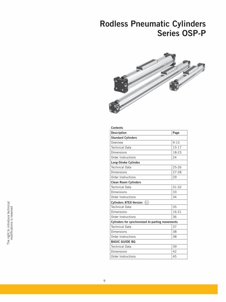
Rodless Pneumatic CylindersSeries OSP-P
Contents
Description Page
Standard Cylinders
Overview 9-13
Technical Data 15-17
Dimensions 18-23
Order Instructions 24
Long-Stroke Cylindes
Technical Data 25-26
Dimensions 27-28
Order Instructions 29
Clean Room Cylinders
Technical Data 31-32
Dimensions 33
Order Instructions 34
Cylinders ATEX-Version
Technical Data 35
Dimensions 16-21
Order Instructions 36
Cylinders for synchronized bi-parting movements
Technical Data 37
Dimensions 38
Order Instructions 38
Technical Data 39
Dimensions 42
Order Instructions 45
10
The
System Concept
and
Components
A completely new generation of linear drives which can be simply and neatly
integrated into any machine layout.
ORIGA SYSTEM PLUS
– INNOVATION FROM A PROVEN DESIGN
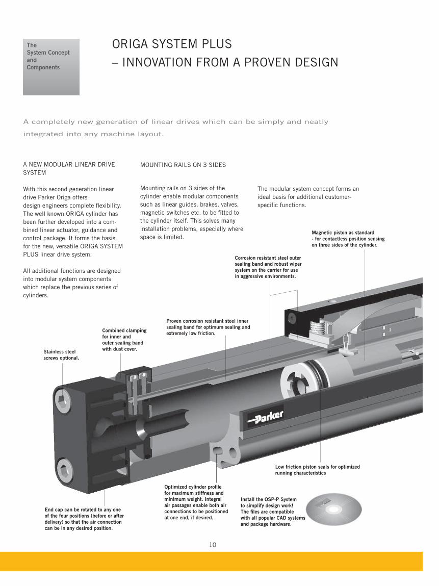
A NEW MODULAR LINEAR DRIVE
SYSTEM
With this second generation linear
drive Parker Origa offers
design engineers complete flexibility.
The well known ORIGA cylinder has
been further developed into a com-
bined linear actuator, guidance and
control package. It forms the basis
for the new, versatile ORIGA SYSTEM
PLUS linear drive system.
All additional functions are designed
into modular system components
which replace the previous series of
cylinders.
MOUNTING RAILS ON 3 SIDES
Mounting rails on 3 sides of the
cylinder enable modular components
such as linear guides, brakes, valves,
magnetic switches etc. to be fitted to
the cylinder itself. This solves many
installation problems, especially where
space is limited.
Stainless steel
screws optional.
End cap can be rotated to any one
of the four positions (before or after
delivery) so that the air connection
can be in any desired position.
Combined clamping
for inner and
outer sealing band
with dust cover.
Corrosion resistant steel outer
sealing band and robust wiper
system on the carrier for use
in aggressive environments.
Proven corrosion resistant steel inner
sealing band for optimum sealing and
extremely low friction.
Magnetic piston as standard
- for contactless position sensing
on three sides of the cylinder.
Optimized cylinder profile
for maximum stiffness and
minimum weight. Integral
air passages enable both air
connections to be positioned
at one end, if desired.
Install the OSP-P System
to simplify design work!
The files are compatible
with all popular CAD systems
and package hardware.
The modular system concept forms an
ideal basis for additional customer-
specific functions.
Low friction piston seals for optimized
running characteristics
11
The r
ight
to intr
oduce t
echnic
al
modifi
cati
ons
is r
ese
rved
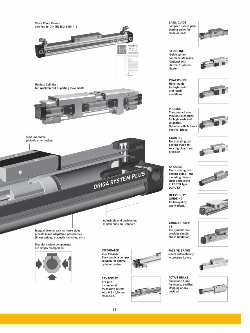
HEAVY DUTY
GUIDE HD
for heavy duty
applications.
PROLINE
The compact alu-
minium roller guide
for high loads and
velocities.
Optional with Active- /
reacts auto mati cally
to pressure failure.
pneumatic brake
for secure, positive
stopping at any
position.
Adjustable end cushioning
at both ends are standard.
New low profile
piston/carrier design.
Integral dovetail rails on three sides
provide many adaptation possibilities
(linear guides, magnetic switches, etc.).
Modular system components
are simply clamped on.
STARLINE
Recirculating ball
bearing guide for
very high loads and
precision.
KF GUIDE
Recirculating ball
bearing guide – the
mounting dimen-
sions correspond
to FESTO Type:
DGPL-KF
SENSOFLEX
SFI-plus
incremental
measuring system
with 0,1 (1,0) mm
resolution.
Clean Room Version
certified to DIN EN ISO 14644-1
INTEGRATED
VOE VALVES
The complete compact
solution for optimal
cylinder control.
VS
The variable stop
provides simple
stroke limitation.
Rodless Cylinder
for synchronized bi-parting movements
POWERSLIDE
Roller guide
for high loads
and rough
conditions.
SLIDELINE
Guide system
for moderate loads.
Optional with
Active- / Passive-
Compact, robust plain
bearing guide for
medium loads.
12
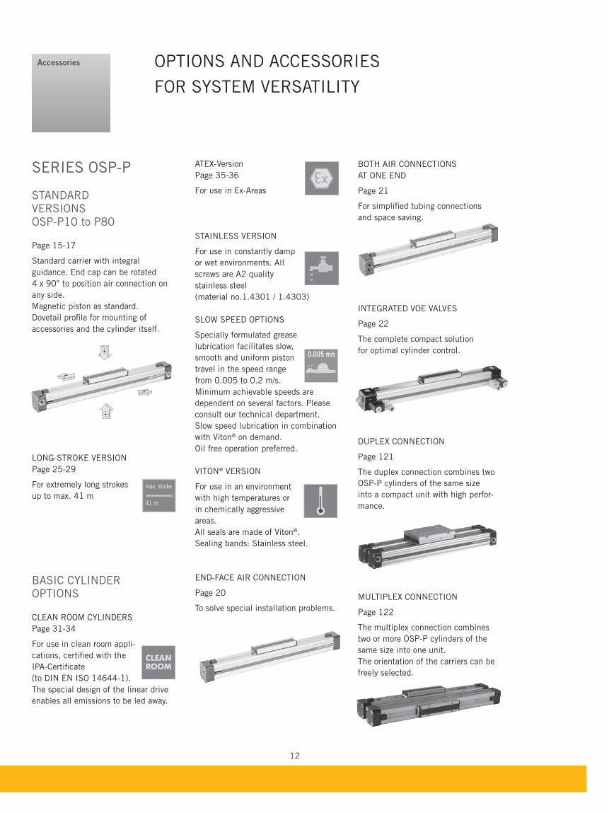
BOTH AIR CONNECTIONS
AT ONE END
Page 21
For simplified tubing connections
and space saving.
INTEGRATED VOE VALVES
Page 22
The complete compact solution
for optimal cylinder control.
DUPLEX CONNECTION
Page 121
The duplex connection combines two
OSP-P cylinders of the same size
into a compact unit with high perfor-
mance.
MULTIPLEX CONNECTION
Page 122
The multiplex connection combines
two or more OSP-P cylinders of the
same size into one unit.
The orientation of the carriers can be
freely selected.
SERIES OSP-P
STANDARDVERSIONSOSP-P10 to P80
Page 15-17
Standard carrier with integral
guidance. End cap can be rotated
4 x 90° to position air connection on
any side.
Magnetic piston as standard.
Dovetail profile for mounting of
accessories and the cylinder itself.
LONG-STROKE VERSION
Page 25-29
For extremely long strokes
up to max. 41 m
BASIC CYLINDER OPTIONS
CLEAN ROOM CYLINDERS
Page 31-34
For use in clean room appli-
cations, certified with the
IPA-Certificate
(to DIN EN ISO 14644-1).
The special design of the linear drive
enables all emissions to be led away.
OPTIONS AND ACCESSORIES
FOR SYSTEM VERSATILITY
Accessories
ATEX-Version
Page 35-36
For use in Ex-Areas
STAINLESS VERSION
For use in constantly damp
or wet environments. All
screws are A2 quality
stainless steel
(material no.1.4301 / 1.4303)
SLOW SPEED OPTIONS
Specially formulated grease
lubrication facilitates slow,
smooth and uniform piston
travel in the speed range
from 0.005 to 0.2 m/s.
Minimum achievable speeds are
dependent on several factors. Please
consult our technical department.
Slow speed lubrication in combination
with Viton® on demand.
Oil free operation preferred.
VITON® VERSION
For use in an environment
with high temperatures or
in chemically aggressive
areas.
All seals are made of Viton®.
Sealing bands: Stainless steel.
END-FACE AIR CONNECTION
Page 20
To solve special installation problems.
0.005 m/s
max. stroke
41 m
13
The r
ight
to intr
oduce t
echnic
al
modifi
cati
ons
is r
ese
rved
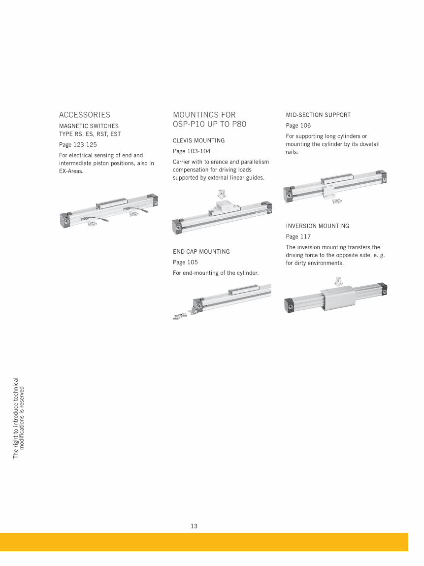
MID-SECTION SUPPORT
Page 106
For supporting long cylinders or
mounting the cylinder by its dovetail
rails.
INVERSION MOUNTING
Page 117
The inversion mounting transfers the
driving force to the opposite side, e. g.
for dirty environments.
MOUNTINGS FOR OSP-P10 UP TO P80
CLEVIS MOUNTING
Page 103-104
Carrier with tolerance and parallelism
compensation for driving loads
supported by external linear guides.
END CAP MOUNTING
Page 105
For end-mounting of the cylinder.
ACCESSORIES
MAGNETIC SWITCHES
TYPE RS, ES, RST, EST
Page 123-125
For electrical sensing of end and
intermediate piston positions, also in
EX-Areas.

14
15
The r
ight
to intr
oduce t
echnic
al
modifi
cati
ons
is r
ese
rved
For linear guides see from page 47For magnetic switches see from page 123For mountings and accessories see from page 101
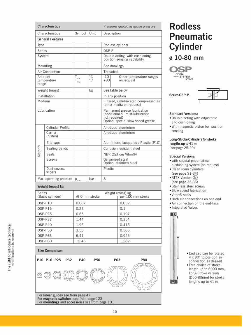
RodlessPneumatic Cylinder ø 10-80 mm
Series OSP-P..
Standard Versions:
Double-acting with adjustable
end cushioning
With magnetic piston for position
sensing
Long-Stroke Cylinders for stroke
lengths up to 41 m
(see page 25-29)
Special Versions:
cushioning system (on request)
(see page 31-34)
(see page 35-36)
® seals
4 x 90° to position air connection as desired
length up to 6000 mm,
Long-Stroke version
(Ø50-80mm) for stroke
lengths up to 41 m
Weight (mass) kg
Series Weight (mass) kg (Basic cylinder) At 0 mm stroke per 100 mm stroke
OSP-P10 0.087 0.052
OSP-P16 0.22 0.1
OSP-P25 0.65 0.197
OSP-P32 1.44 0.354
OSP-P40 1.95 0.415
OSP-P50 3.53 0.566
OSP-P63 6.41 0.925
OSP-P80 12.46 1.262
Size Comparison
P10 P16 P25 P32 P40 P50 P63 P80
Characteristics Pressures quoted as gauge pressure
Characteristics Symbol Unit Description
General Features
Type Rodless cylinder
Series OSP-P
System Double-acting, with cushioning, position sensing capability
Mounting See drawings
Air Connection Threaded
Ambient Tmin
°C -10 Other temperature ranges temperature T
max °C +80 on request
range
Weight (mass) kg See table below
Installation In any position
Medium Filtered, unlubricated compressed air (other media on request) Lubrication Permanent grease lubrication (additional oil mist lubrication not required) Option: special slow speed grease
Cylinder Profile Anodized aluminium
Carrier Anodized aluminium (piston)
End caps Aluminium, lacquered / Plastic (P10)
Sealing bands Corrosion resistant steel
Seals NBR (Option: Viton®)
Screws Galvanized steel Option: stainless steel
Dust covers, Plastic wipers
Max. operating pressure pmax
bar 8
Mate
rial
ORIGA
SYSTEM
PLUS
OSP
16
0,2
0,30,40,5
1
0,1
2
345
0,1 0,20,3 0,5 1 2 3 5 10 100 1000
m/s
kg
D40
D32
D25D16D50
D63D80
D10
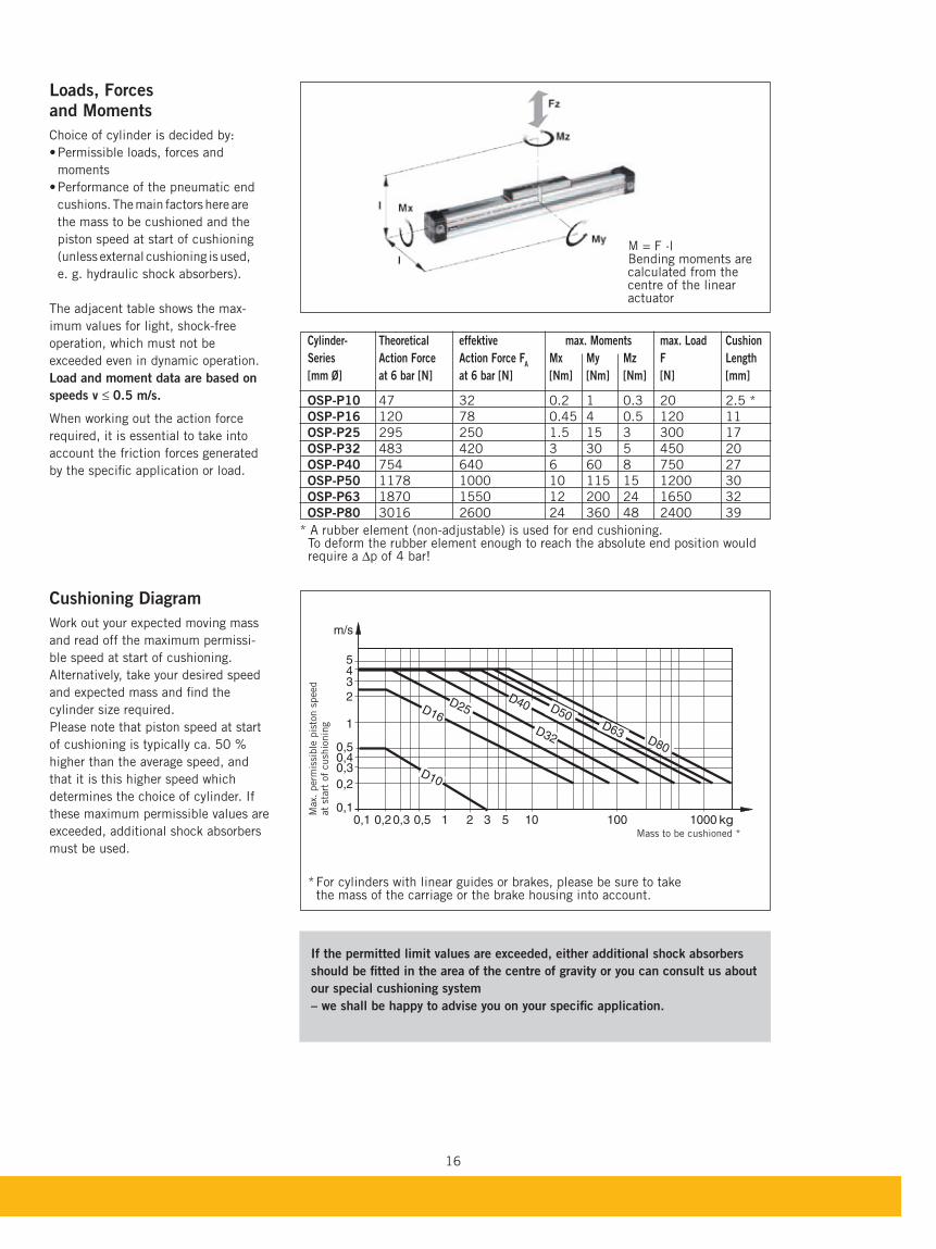
Cylinder- Theoretical effektive max. Moments max. Load Cushion
Series Action Force Action Force FA Mx My Mz F Length
[mm Ø] at 6 bar [N] at 6 bar [N] [Nm] [Nm] [Nm] [N] [mm]
OSP-P10 47 32 0.2 1 0.3 20 2.5 *
OSP-P16 120 78 0.45 4 0.5 120 11
OSP-P25 295 250 1.5 15 3 300 17
OSP-P32 483 420 3 30 5 450 20
OSP-P40 754 640 6 60 8 750 27
OSP-P50 1178 1000 10 115 15 1200 30
OSP-P63 1870 1550 12 200 24 1650 32
OSP-P80 3016 2600 24 360 48 2400 39
Loads, Forcesand Moments
Choice of cylinder is decided by:
Permissible loads, forces and
moments
Performance of the pneumatic end
cushions. The main factors here are
the mass to be cushioned and the
piston speed at start of cushioning
(unless external cushioning is used,
e. g. hydraulic shock absorbers).
The adjacent table shows the max-
imum values for light, shock-free
operation, which must not be
exceeded even in dynamic operation.
Load and moment data are based on
speeds v ≤ 0.5 m/s.
When working out the action force
required, it is essential to take into
account the friction forces generated
by the specific application or load.
Cushioning Diagram
Work out your expected moving mass
and read off the maximum permissi-
ble speed at start of cushioning.
Alternatively, take your desired speed
and expected mass and find the
cylinder size required.
Please note that piston speed at start
of cushioning is typically ca. 50 %
higher than the average speed, and
that it is this higher speed which
determines the choice of cylinder. If
these maximum permissible values are
exceeded, additional shock absorbers
must be used.
M = F ·l Bending moments are calculated from the centre of the linear actuator
* A rubber element (non-adjustable) is used for end cushioning. To deform the rubber element enough to reach the absolute end position would require a ∆p of 4 bar!
* For cylinders with linear guides or brakes, please be sure to take the mass of the carriage or the brake housing into account.
Max.
perm
issi
ble
pis
ton s
peed
at
start
of
cush
ionin
g
Mass to be cushioned *
If the permitted limit values are exceeded, either additional shock absorbers
should be fitted in the area of the centre of gravity or you can consult us about
our special cushioning system
– we shall be happy to advise you on your specific application.
M Beca
17
The r
ight
to intr
oduce t
echnic
al
modifi
cati
ons
is r
ese
rved
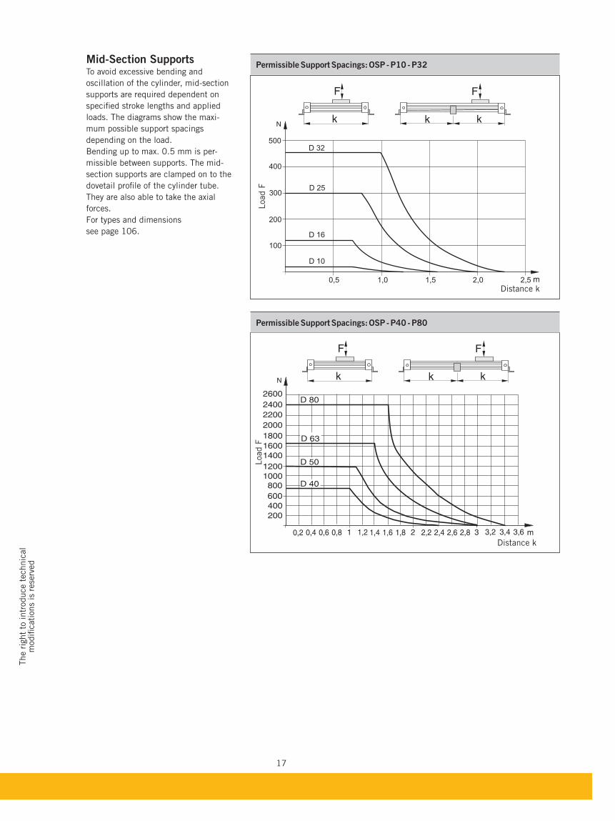
Mid-Section SupportsTo avoid excessive bending and
oscillation of the cylinder, mid-section
supports are required dependent on
specified stroke lengths and applied
loads. The diagrams show the maxi-
mum possible support spacings
depending on the load.
Bending up to max. 0.5 mm is per-
missible between supports. The mid-
section supports are clamped on to the
dovetail profile of the cylinder tube.
They are also able to take the axial
forces.
For types and dimensions
see page 106.
D 25
D 32
D 16
D 10
100
200
300
400
500
0,5 1,0 1,5 2,0 2,5
Distance k
Load F
Permissible Support Spacings: OSP - P10 - P32
k k
FF
k
Distance k
Load F
Permissible Support Spacings: OSP - P40 - P80
k k
FF
k
18
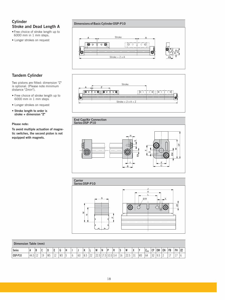
Cylinder Stroke and Dead Length A
6000 mm in 1 mm steps.
Tandem Cylinder
Two pistons are fitted: dimension "Z" is optional. (Please note minimum distance "Zmin").
6000 mm in 1 mm steps
Stroke length to order is stroke + dimension "Z"
Please note:
To avoid multiple actuation of magne-
tic switches, the second piston is not
equipped with magnets.
A A
FH
K
FB
A Z
Stroke
Stroke + 2 x A
Stroke
Stroke + 2 x A + Z
End Cap/Air ConnectionSeries OSP -P10
I
B
GH
EN
E
E
W
CF
D
EM
C
CarrierSeries OSP-P10
L
J
X
Ø RS
N
P
M
ZZ
Y
Dimension Table (mm)
min
OSP-P10 44.5 12 19 M5 12 M3 5 6 60 8.5 22 22.5 17.5 10.5 3.4 16 22.5 31 M3 64 32 9.5 2 17 17 6
19
The r
ight
to intr
oduce t
echnic
al
modifi
cati
ons
is r
ese
rved
Z AA Z
CF
O EN
BX
BY
BW
I
B
K
BX
EN
C E
E
C
G x H
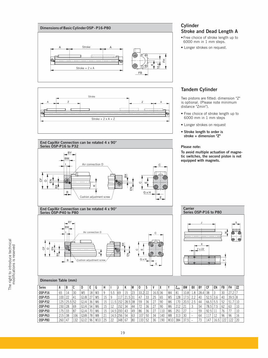
Dimension Table (mm)
min
OSP-P16 65 14 30 M5 18 M3 9 5.5 69 15 23 33.2 22 16.5 36 M4 81 10.8 1.8 28.4 38 3 30 27.2 7
OSP-P25 100 22 41 G1/8 27 M5 15 9 117 21.5 31 47 33 25 65 M5 128 17.5 2.2 40 52.5 3.6 40 39.5 8
OSP-P32 125 25.5 52 G1/4 36 M6 15 11.5 152 28.5 38 59 36 27 90 M6 170 20.5 2.5 44 66.5 5.5 52 51.7 10
OSP-P40 150 28 69 G1/4 54 M6 15 12 152 34 44 72 36 27 90 M6 212 21 3 54 78.5 7.5 62 63 10
OSP-P50 175 33 87 G1/4 70 M6 15 14.5 200 43 49 86 36 27 110 M6 251 27 – 59 92.5 11 76 77 10
OSP-P63 215 38 106 G3/8 78 M8 21 14.5 256 54 63 107 50 34 140 M8 313 30 – 64 117 12 96 96 16
OSP-P80 260 47 132 G1/2 96 M10 25 22 348 67 80 133 52 36 190 M10 384 37.5 – 73 147 16.5 122 122 20
End Cap/Air Connection can be rotated 4 x 90°Series OSP-P16 to P32
End Cap/Air Connection can be rotated 4 x 90°Series OSP-P40 to P80
CarrierSeries OSP-P16 to P80
Cylinder Stroke and Dead Length A
6000 mm in 1 mm steps.
Tandem Cylinder
Two pistons are fitted: dimension "Z" is optional. (Please note minimum distance "Zmin").
6000 mm in 1 mm steps
Stroke length to order is stroke + dimension "Z"
Please note:
To avoid multiple actuation of magne-tic switches, the second piston is not equipped with magnets.
FB
K
10,4
FH
A AStroke
Stroke + 2 x A
BY
CF
O
EN
BX
BW
I
B
K
BX
EN
C E
C
E
G x H
J
X
Y x ZZ
VM
S
Air connection D
Cushion adjustment screw
Air connection D
Cushion adjustment screw
Stroke
Stroke + 2 x A + Z
20
BX
B
BX
C E
C
E
G x HCushion adjustment screw
Air connection D
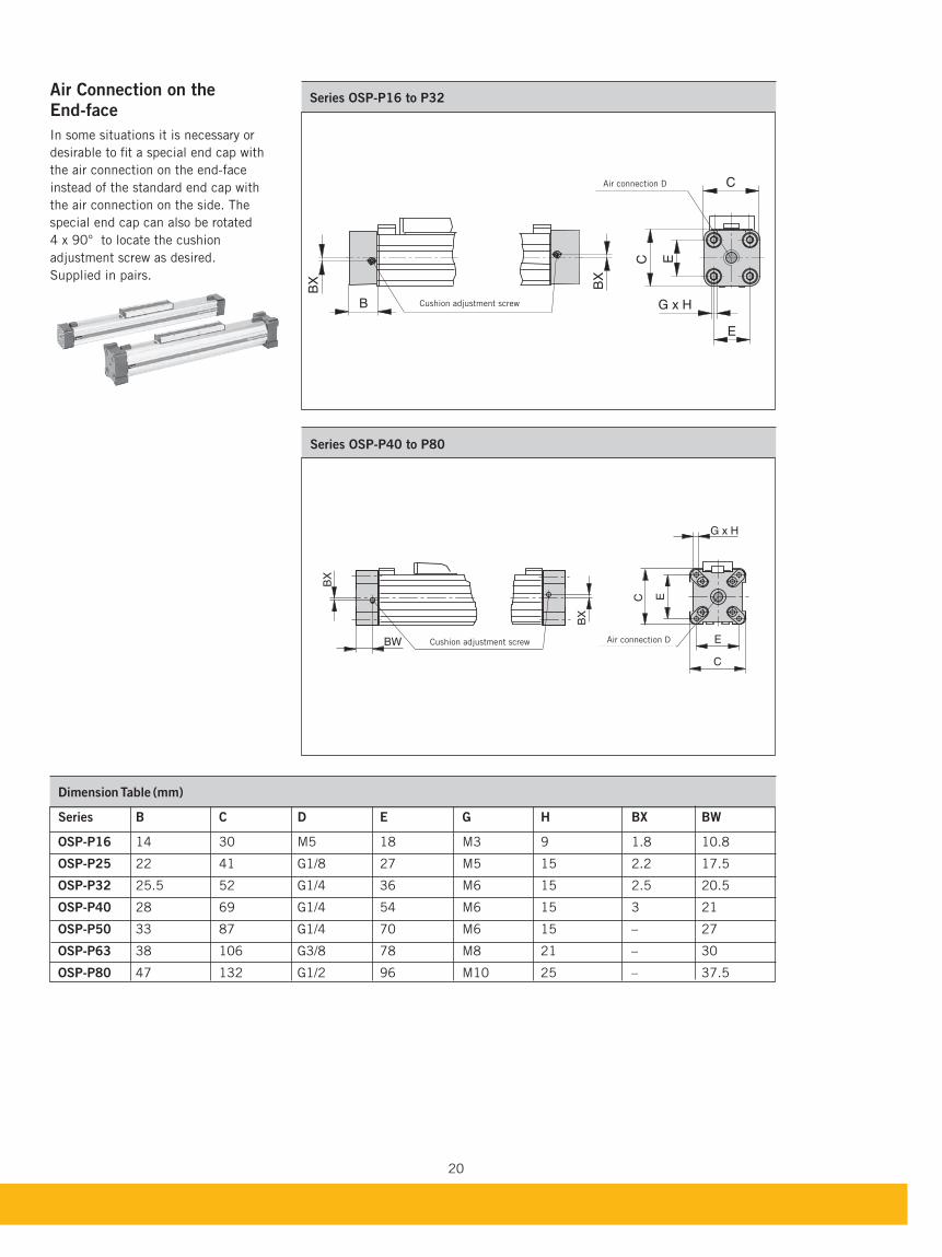
Dimension Table (mm)
OSP-P16 14 30 M5 18 M3 9 1.8 10.8
OSP-P25 22 41 G1/8 27 M5 15 2.2 17.5
OSP-P32 25.5 52 G1/4 36 M6 15 2.5 20.5
OSP-P40 28 69 G1/4 54 M6 15 3 21
OSP-P50 33 87 G1/4 70 M6 15 – 27
OSP-P63 38 106 G3/8 78 M8 21 – 30
OSP-P80 47 132 G1/2 96 M10 25 – 37.5
Series OSP-P40 to P80
Series OSP-P16 to P32Air Connection on the End-face
In some situations it is necessary or
desirable to fit a special end cap with
the air connection on the end-face
instead of the standard end cap with
the air connection on the side. The
special end cap can also be rotated
4 x 90° to locate the cushion
adjustment screw as desired.
Supplied in pairs.
BX
C EC
BX
BW E
G x H
Cushion adjustment screw Air connection D
21
The r
ight
to intr
oduce t
echnic
al
modifi
cati
ons
is r
ese
rved
BX
B
BX
C E
C
E
G x H
1*
2*
2*
1*
l1
BW
EN
1
EN
2
Cushion adjustment screw
Air connection D
BX
B
BX
EN
FL
BWBW
I1
C
FB
FG
FA
FC
FE
E
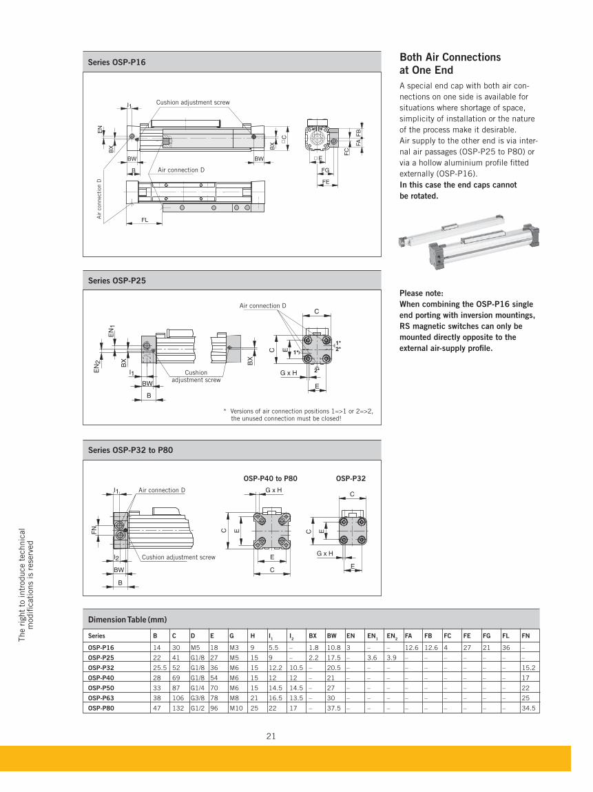
Series OSP-P16at One End
A special end cap with both air con-
nections on one side is available for
situations where shortage of space,
simplicity of installation or the nature
of the process make it desirable.
Air supply to the other end is via inter-
nal air passages (OSP-P25 to P80) or
via a hollow aluminium profile fitted
externally (OSP-P16).
In this case the end caps cannot
be rotated.
Dimension Table (mm)
1 I
2 1 EN
2
OSP-P16 14 30 M5 18 M3 9 5.5 – 1.8 10.8 3 – – 12.6 12.6 4 27 21 36 –
OSP-P25 22 41 G1/8 27 M5 15 9 – 2.2 17.5 – 3.6 3.9 – – – – – – –
OSP-P32 25.5 52 G1/8 36 M6 15 12.2 10.5 – 20.5 – – – – – – – – – 15.2
OSP-P40 28 69 G1/8 54 M6 15 12 12 – 21 – – – – – – – – – 17
OSP-P50 33 87 G1/4 70 M6 15 14.5 14.5 – 27 – – – – – – – – – 22
OSP-P63 38 106 G3/8 78 M8 21 16.5 13.5 – 30 – – – – – – – – – 25
OSP-P80 47 132 G1/2 96 M10 25 22 17 – 37.5 – – – – – – – – – 34.5
Series OSP-P25
Series OSP-P32 to P80
G x H
EC
E
C
I2
BW
B
FN
I1
C E
C
E
G x HCushion adjustment screw
Air connection D
OSP-P40 to P80 OSP-P32
Please note:
When combining the OSP-P16 single
end porting with inversion mountings,
RS magnetic switches can only be
mounted directly opposite to the
external air-supply profile.
Cushion adjustment screw
Air connection D
Air
connecti
on D
* Versions of air connection positions 1=>1 or 2=>2, the unused connection must be closed!
22
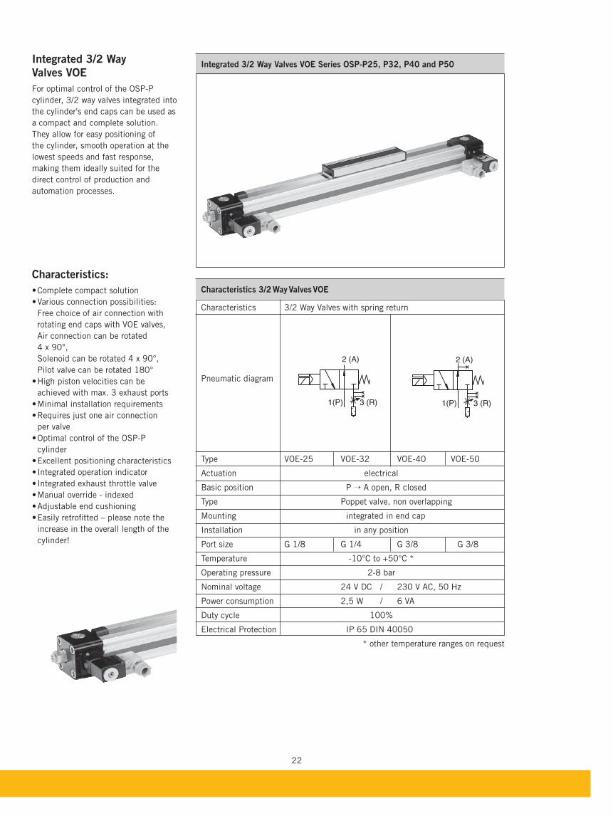
Integrated 3/2 Way Valves VOE Series OSP-P25, P32, P40 and P50Integrated 3/2 Way
Valves VOE
For optimal control of the OSP-P
cylinder, 3/2 way valves integrated into
the cylinder's end caps can be used as
a compact and complete solution.
They allow for easy positioning of
the cylinder, smooth operation at the
lowest speeds and fast response,
making them ideally suited for the
direct control of production and
automation processes.
Characteristics:
Free choice of air connection with
rotating end caps with VOE valves,
Air connection can be rotated
4 x 90°,
Solenoid can be rotated 4 x 90°,
Pilot valve can be rotated 180°
achieved with max. 3 exhaust ports
per valve
cylinder
increase in the overall length of the
cylinder!
Characteristics 3/2 Way Valves VOE
Characteristics 3/2 Way Valves with spring return
Pneumatic diagram
Type VOE-25 VOE-32 VOE-40 VOE-50
Actuation electrical
Basic position P Õ A open, R closed
Type Poppet valve, non overlapping
Mounting integrated in end cap
Installation in any position
Port size G 1/8 G 1/4 G 3/8 G 3/8
Temperature -10°C to +50°C *
Operating pressure 2-8 bar
Nominal voltage 24 V DC / 230 V AC, 50 Hz
Power consumption 2,5 W / 6 VA
Duty cycle 100%
Electrical Protection IP 65 DIN 40050
* other temperature ranges on request
2 (A)
1(P) 3 (R)
2 (A)
1(P) 3 (R)
23
The r
ight
to intr
oduce t
echnic
al
modifi
cati
ons
is r
ese
rved
V9
V8
DV1(P)*
V16
V18
V19
V15
V17
BV
V12
V11
V3
V1V2
AVCV
C
V10V7
V6 V13 V14
CV5
V4
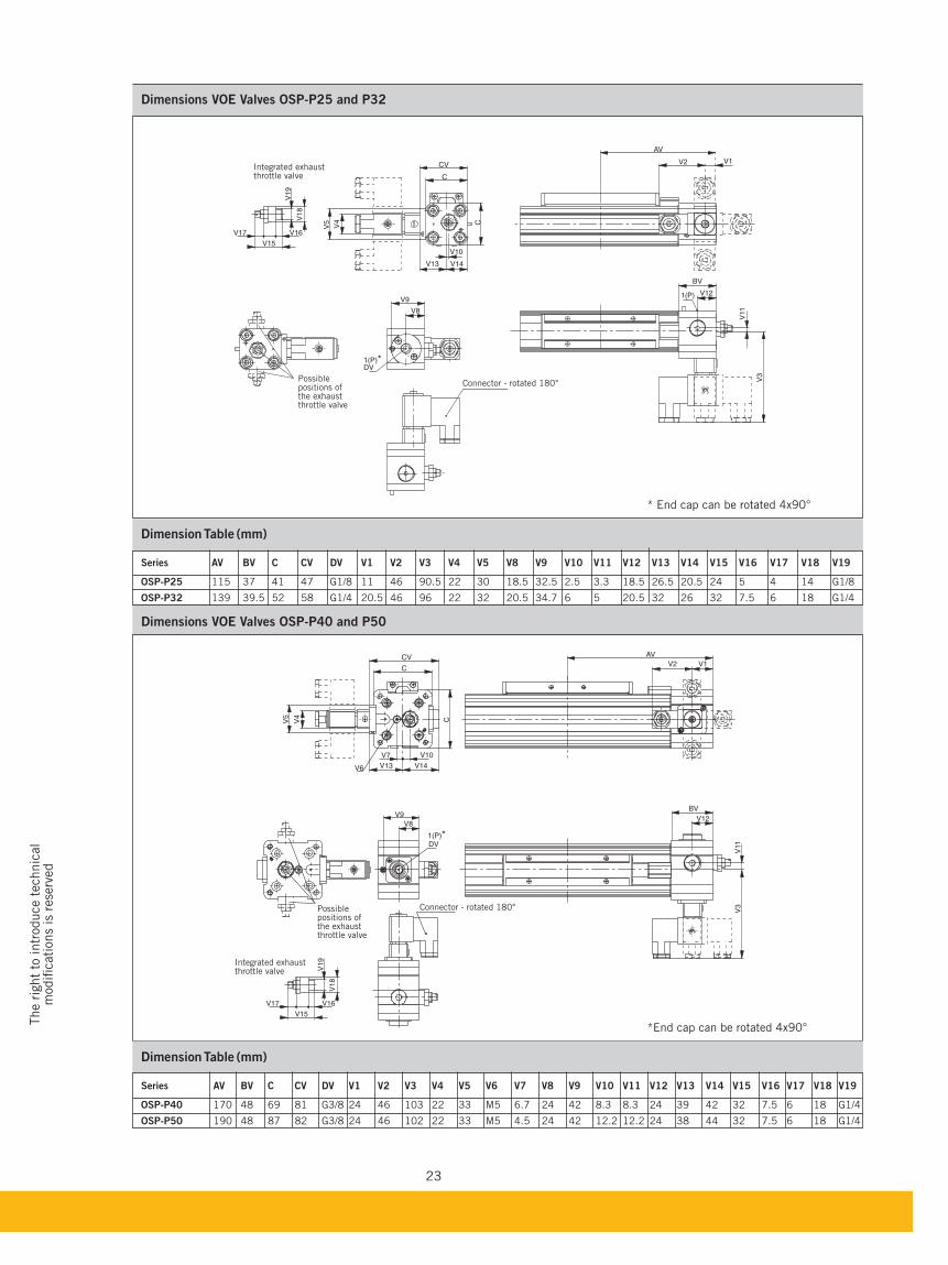
Dimensions VOE Valves OSP-P40 and P50
Dimension Table (mm)
OSP-P40 170 48 69 81 G3/8 24 46 103 22 33 M5 6.7 24 42 8.3 8.3 24 39 42 32 7.5 6 18 G1/4
OSP-P50 190 48 87 82 G3/8 24 46 102 22 33 M5 4.5 24 42 12.2 12.2 24 38 44 32 7.5 6 18 G1/4
Dimensions VOE Valves OSP-P25 and P32
Dimension Table (mm)
OSP-P25 115 37 41 47 G1/8 11 46 90.5 22 30 18.5 32.5 2.5 3.3 18.5 26.5 20.5 24 5 4 14 G1/8
OSP-P32 139 39.5 52 58 G1/4 20.5 46 96 22 32 20.5 34.7 6 5 20.5 32 26 32 7.5 6 18 G1/4
Connector - rotated 180° Possiblepositions ofthe exhaustthrottle valve
Integrated exhaustthrottle valve
V10
V16
V18
V19
V15
V17
CV
C
C
V14V13
V9
V8
1(P)*DV
BV
V121(P)
V11
V3
AV
V2 V1
V5
V4
Possiblepositions ofthe exhaustthrottle valve
Integrated exhaust throttle valve
Connector - rotated 180°
*End cap can be rotated 4x90°
* End cap can be rotated 4x90°
24
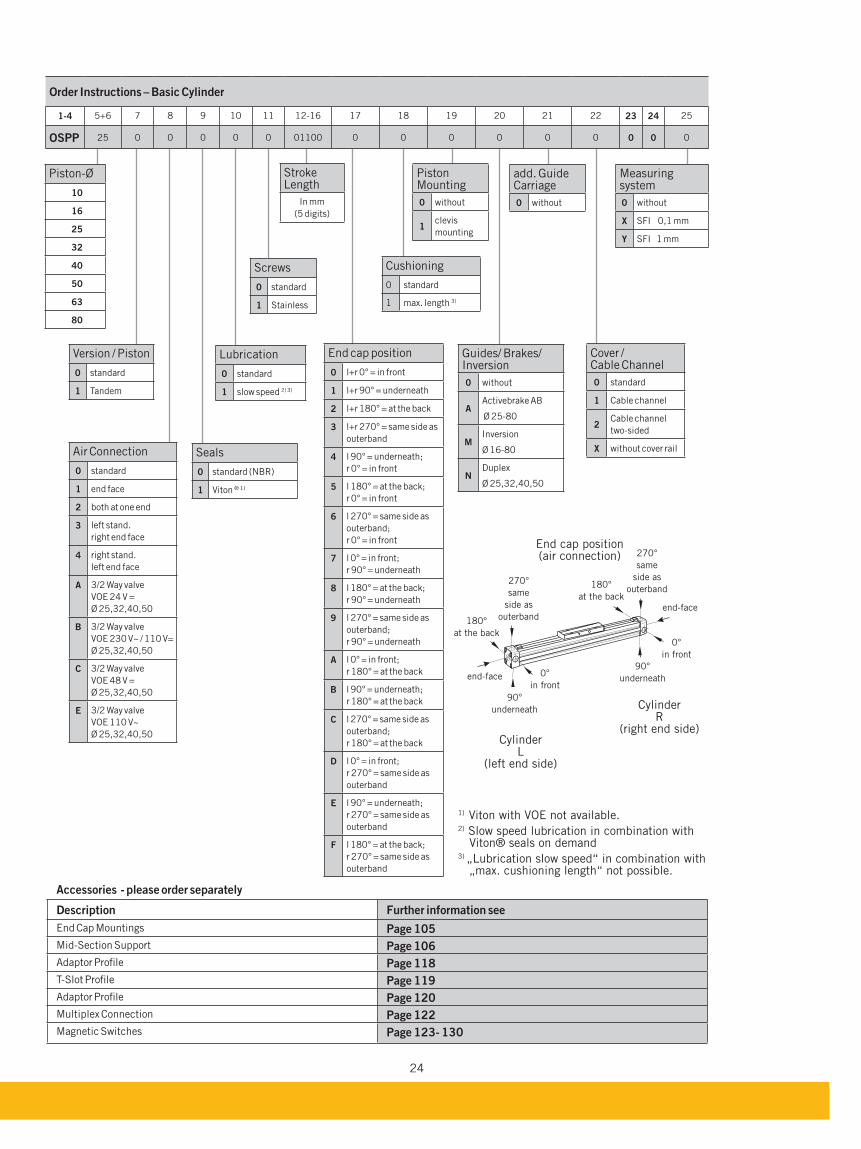
1-4 5+6 7 8 9 10 11 12-16 17 18 19 20 21 22 23 24 25
OSPP 25 0 0 0 0 0 01100 0 0 0 0 0 0 0 0 0
End cap position
0 l+r 0° = in front
1 l+r 90° = underneath
2 l+r 180° = at the back
3 l+r 270° = same side as
outerband
4 l 90° = underneath;
r 0° = in front
5 l 180° = at the back;
r 0° = in front
6 l 270° = same side as
outerband;
r 0° = in front
7 l 0° = in front;
r 90° = underneath
8 l 180° = at the back;
r 90° = underneath
9 l 270° = same side as
outerband;
r 90° = underneath
A l 0° = in front;
r 180° = at the back
l 90° = underneath;
r 180° = at the back
C l 270° = same side as
outerband;
r 180° = at the back
D l 0° = in front;
r 270° = same side as
outerband
E l 90° = underneath;
r 270° = same side as
outerband
F l 180° = at the back;
r 270° = same side as
outerband
Version / Piston
0 standard
1 Tandem
Seals
0 standard (NBR)
1 Viton ® 1)
Lubrication
0 standard
1 slow speed 2) 3)
add. Guide Carriage
0 without
Screws
0 standard
1 Stainless
Cushioning
0 standard
1 max. length 3)
Piston Mounting
0 without
1clevis
mounting
Guides/ Brakes/ Inversion
0 without
AActivebrake AB
Ø 25-80
MInversion
Ø 16-80
NDuplex
Ø 25,32,40,50
Cover / Cable Channel
0 standard
1 Cable channel
2Cable channel
two-sided
X without cover rail
Measuring system
0 without
X SFI 0,1 mm
Y SFI 1 mm
Stroke Length
In mm
(5 digits)
Piston-Ø
10
16
25
32
40
50
63
80
1) Viton with VOE not available.2) Slow speed lubrication in combination with
Viton® seals on demand3) „Lubrication slow speed“ in combination with
„max. cushioning length“ not possible.
Air Connection
0 standard
1 end face
2 both at one end
3 left stand.
right end face
4 right stand.
left end face
A 3/2 Way valve
VOE 24 V =
Ø 25,32,40,50
3/2 Way valve
VOE 230 V~ / 110 V=
Ø 25,32,40,50
C 3/2 Way valve
VOE 48 V =
Ø 25,32,40,50
E 3/2 Way valve
VOE 110 V~
Ø 25,32,40,50
Accessories - please order separately
Description Further information see
End Cap Mountings Page 105
Mid-Section Support Page 106
Adaptor Profile Page 118
T-Slot Profile Page 119
Adaptor Profile Page 120
Multiplex Connection Page 122
Magnetic Switches Page 123- 130
270°
same
side as
outerband
270°
same
side as
outerband
0°
in front
0°
in front
180°
at the back
180°
at the back
90°
underneath
90°
underneath
end-face
end-face
End cap position (air connection)
Cylinder L
(left end side)
Cylinder R
(right end side)
25
The r
ight
to intr
oduce t
echnic
al
modifi
cati
ons
is r
ese
rved
For magnetic switches see from page 123Accessories see from page 101
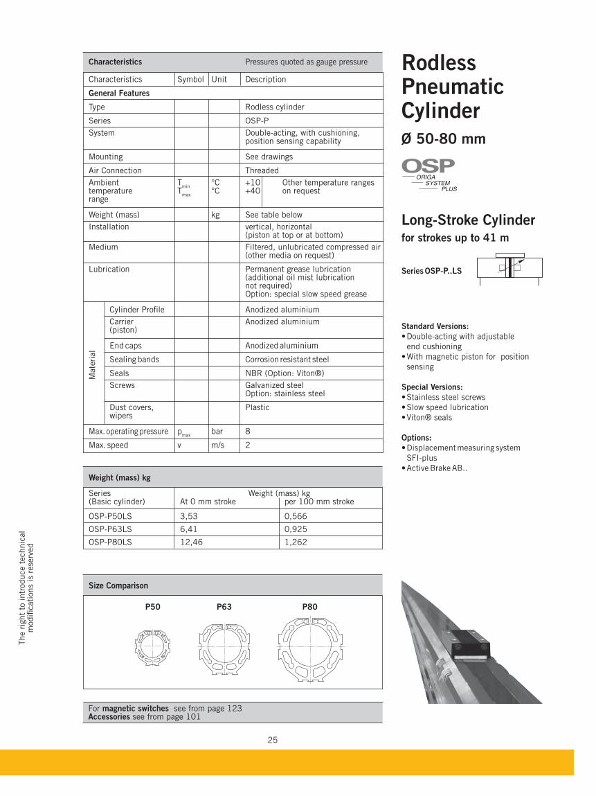
RodlessPneumatic Cylinder Ø 50-80 mm
Long-Stroke Cylinderfor strokes up to 41 m
Series OSP-P..LS
Standard Versions:
Double-acting with adjustable
end cushioning
With magnetic piston for position
sensing
Special Versions:
® seals
Options:
SFI-plus
Weight (mass) kg
Series Weight (mass) kg (Basic cylinder) At 0 mm stroke per 100 mm stroke
OSP-P50LS 3,53 0,566
OSP-P63LS 6,41 0,925
OSP-P80LS 12,46 1,262
Size Comparison
P50 P63 P80
ORIGA
SYSTEM
PLUS
OSP
Characteristics Pressures quoted as gauge pressure
Characteristics Symbol Unit Description
General Features
Type Rodless cylinder
Series OSP-P
System Double-acting, with cushioning, position sensing capability
Mounting See drawings
Air Connection Threaded
Ambient Tmin
°C +10 Other temperature ranges temperature T
max °C +40 on request
range
Weight (mass) kg See table below
Installation vertical, horizontal (piston at top or at bottom)
Medium Filtered, unlubricated compressed air (other media on request) Lubrication Permanent grease lubrication (additional oil mist lubrication not required) Option: special slow speed grease
Cylinder Profile Anodized aluminium
Carrier Anodized aluminium (piston)
End caps Anodized aluminium
Sealing bands Corrosion resistant steel
Seals NBR (Option: Viton®)
Screws Galvanized steel Option: stainless steel
Dust covers, Plastic wipers
Max. operating pressure pmax
bar 8
Max. speed v m/s 2
Mate
rial
26
0,2
0,30,40,5
1
0,1
2
345
1 2 3 5 10 100 1000
m/s
kg
D50D63
D80
Theoretical effektive max. Moments max. Load Cushion
Series Action Force Action Force FA Mx My Mz F Length
[mm Ø] at 6 bar [N] at 6 bar [N] [Nm] [Nm] [Nm] [N] [mm]
OSP-P50LS 1178 1000 10 115 15 1200 30
OSP-P63LS 1870 1550 12 200 24 1650 32
OSP-P80LS 3016 2600 24 360 48 2400 39
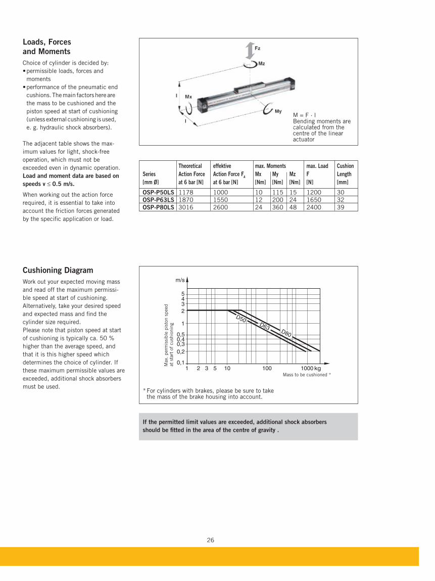
Loads, Forcesand Moments
Choice of cylinder is decided by:
moments
cushions. The main factors here are
the mass to be cushioned and the
piston speed at start of cushioning
(unless external cushioning is used,
e. g. hydraulic shock absorbers).
The adjacent table shows the max-
imum values for light, shock-free
operation, which must not be
exceeded even in dynamic operation.
Load and moment data are based on
speeds v ≤ 0.5 m/s.
When working out the action force
required, it is essential to take into
account the friction forces generated
by the specific application or load.
Cushioning Diagram
Work out your expected moving mass
and read off the maximum permissi-
ble speed at start of cushioning.
Alternatively, take your desired speed
and expected mass and find the
cylinder size required.
Please note that piston speed at start
of cushioning is typically ca. 50 %
higher than the average speed, and
that it is this higher speed which
determines the choice of cylinder. If
these maximum permissible values are
exceeded, additional shock absorbers
must be used.
M = F · l Bending moments are calculated from the centre of the linear actuator
* For cylinders with brakes, please be sure to take the mass of the brake housing into account.
Max.
perm
issi
ble
pis
ton s
peed
at
start
of
cush
ionin
g
Mass to be cushioned *
If the permitted limit values are exceeded, additional shock absorbers
should be fitted in the area of the centre of gravity .
M Beca
27
The r
ight
to intr
oduce t
echnic
al
modifi
cati
ons
is r
ese
rved
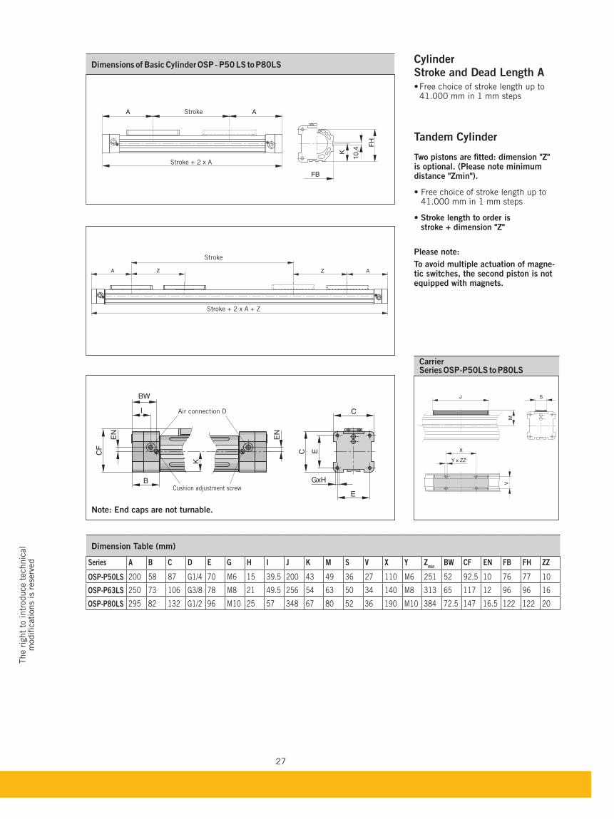
CarrierSeries OSP-P50LS to P80LS
Z AA Z
BW
I
B
CF
EN
EN
K
C
E
GxH
EC
Dimension Table (mm)
Series A C D E G H I K M S V X Y Zmin
CF EN FH ZZ
OSP-P50LS 200 58 87 G1/4 70 M6 15 39.5 200 43 49 36 27 110 M6 251 52 92.5 10 76 77 10
OSP-P63LS 250 73 106 G3/8 78 M8 21 49.5 256 54 63 50 34 140 M8 313 65 117 12 96 96 16
OSP-P80LS 295 82 132 G1/2 96 M10 25 57 348 67 80 52 36 190 M10 384 72.5 147 16.5 122 122 20
Cylinder Stroke and Dead Length A
41.000 mm in 1 mm steps
Tandem Cylinder
Two pistons are fitted: dimension "Z" is optional. (Please note minimum distance "Zmin").
41.000 mm in 1 mm steps
Stroke length to order is stroke + dimension "Z"
Please note:
To avoid multiple actuation of magne-tic switches, the second piston is not equipped with magnets.
Air connection D
Cushion adjustment screw
Stroke + 2 x A + Z
Stroke
Note: End caps are not turnable.
Stroke
Stroke + 2 x A
A A
FB
K
10,4
FH
M
J
X
Y x ZZ
V
S
28
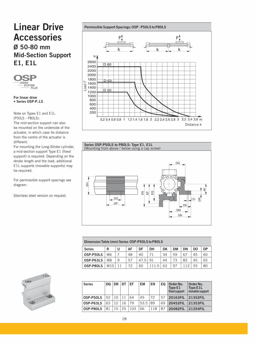
Series OSP-P50LS to P80LS: Type E1, E1L (Mounting from above / below using a cap screw)
Linear DriveAccessoriesØ 50-80 mm
Mid-Section Support
E1, E1L
For linear drive
Note on Types E1 and E1L
(P50LS – P80LS):
The mid-section support can also
be moun ted on the underside of the
actuator, in which case its distance
from the centre of the actuator is
different.
For mounting the Long-Stroke cylinder,
a mid-section support Type E1 (fixed
support) is required. Depending on the
stroke length and the load, additional
E1L supports (movable supports) may
be required.
For permissible support spacings see
diagram.
Stainless steel version on request.
DP
DH
DO
DK
EQ
EF
EN
DM
DN
AF
ÆU
DQ
DR
ORIGA
SYSTEM
PLUS
OSP
Dimension Table (mm) Series OSP-P50LS to P80LS
Series R U AF DF DH DK DM DN DO DP
OSP-P50LS M6 7 48 40 71 34 59 67 45 60
OSP-P63LS M8 9 57 47.5 91 44 73 83 45 65
OSP-P80LS M10 11 72 60 111.5 63 97 112 55 80
k k
FF
k
1 2 3
600
400
1200
200
1000
800
0,2 0,4 0,6 0,8 1,2 1,4 1,6 1,8 2,2 2,4 2,6 2,8
D 501400
1600
1800
2000
2200
2400
2600
3,2 3,4 3,6
D 80
D 63
N
m
Distance k
Load F
Permissible Support Spacings: OSP - P50LS to P80LS
Series DQ DR DT EF EM EN EQ Order No.Type E1fixed support
Order No.Type E1Lmovable support
OSP-P50LS 52 10 11 64 45 72 57 20163FIL 21352FIL
OSP-P63LS 63 12 16 79 53.5 89 69 20452FIL 21353FIL
OSP-P80LS 81 15 25 103 66 118 87 20482FIL 21354FIL
29
The r
ight
to intr
oduce t
echnic
al
modifi
cati
ons
is r
ese
rved
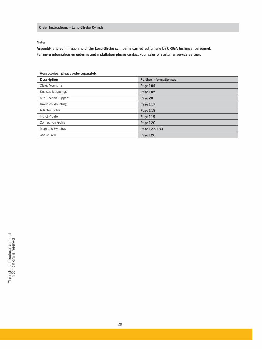
Order Instructions – Long-Stroke Cylinder
Note:
Assembly and commissioning of the Long-Stroke cylinder is carried out on site by ORIGA technical personnel.
For more information on ordering and installation please contact your sales or customer service partner.
Accessories - please order separately
Description Further information see
Clevis Mounting Page 104
End Cap Mountings Page 105
Mid-Section Support Page 28
Inversion Mounting Page 117
Adaptor Profile Page 118
T-Slot Profile Page 119
Connection Profile Page 120
Magnetic Switches Page 123-133
Cable Cover Page 126

30
31
The r
ight
to intr
oduce t
echnic
al
modifi
cati
ons
is r
ese
rved
For magnetic switches see from page 123For mountings and accessories see from page 101-122
Series OSP-P..
Standard Versions:
Double-acting with adjustable
end cushioning
With magnetic piston for position
sensing
Special Versions:
® seals
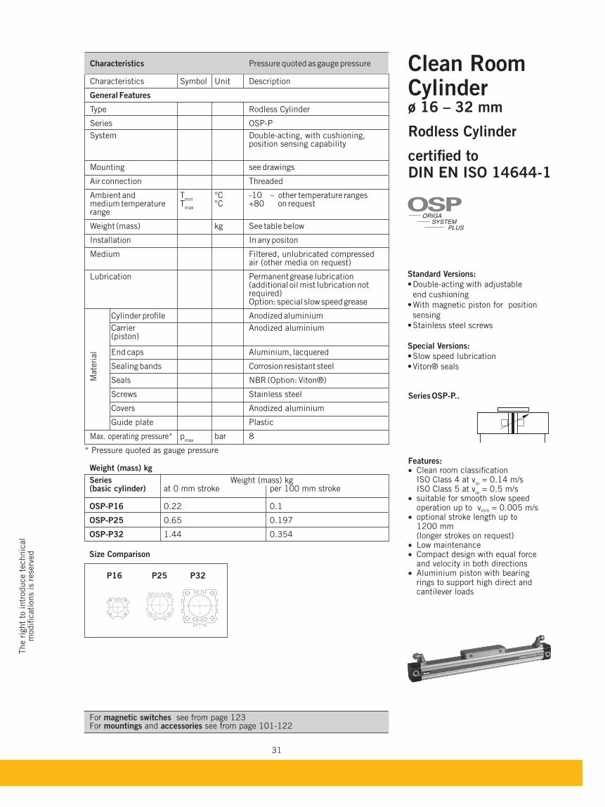
Weight (mass) kg Series Weight (mass) kg (basic cylinder) at 0 mm stroke per 100 mm stroke
OSP-P16 0.22 0.1
OSP-P25 0.65 0.197
OSP-P32 1.44 0.354
Size Comparison
P16 P25 P32
Characteristics Pressure quoted as gauge pressure
Characteristics Symbol Unit Description
General Features
Type Rodless Cylinder
Series OSP-P
System Double-acting, with cushioning, position sensing capability
Mounting see drawings
Air connection Threaded
Ambient and Tmin
°C -10 – other temperature ranges medium temperature T
max °C +80 on request
range
Weight (mass) kg See table below
Installation In any positon
Medium Filtered, unlubricated compressed air (other media on request) Lubrication Permanent grease lubrication (additional oil mist lubrication not required) Option: special slow speed grease
Cylinder profile Anodized aluminium
Carrier Anodized aluminium (piston)
End caps Aluminium, lacquered
Sealing bands Corrosion resistant steel
Seals NBR (Option: Viton®)
Screws Stainless steel
Covers Anodized aluminium
Guide plate Plastic
Max. operating pressure* pmax
bar 8
* Pressure quoted as gauge pressure
Mate
rial
Clean Room Cylinderø 16 – 32 mm
Rodless Cylinder
certified toDIN EN ISO 14644-1
Features: Clean room classification
ISO Class 4 at vm = 0.14 m/s
ISO Class 5 at vm = 0.5 m/s
suitable for smooth slow speed operation up to vmin = 0.005 m/s optional stroke length up to
1200 mm (longer strokes on request) Low maintenance Compact design with equal force
and velocity in both directions Aluminium piston with bearing
rings to support high direct and cantilever loads
ORIGA
SYSTEM
PLUS
OSP
32
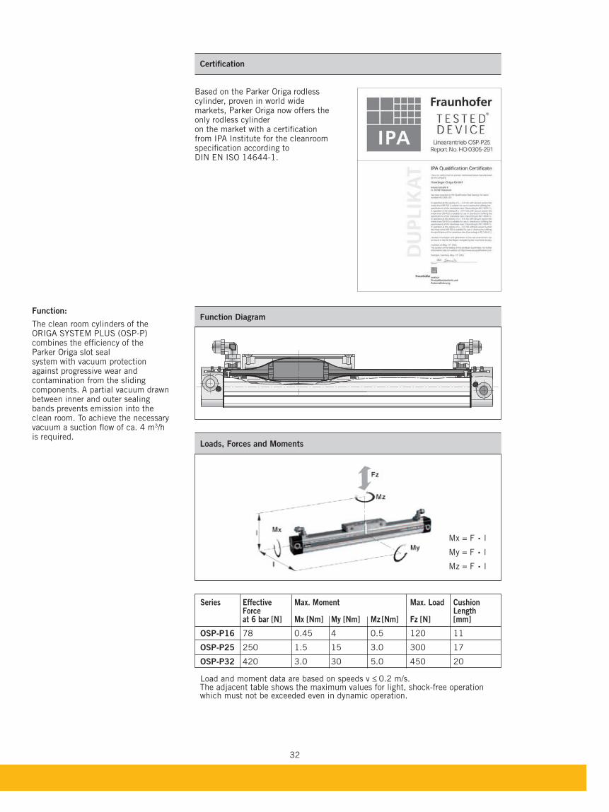
Function:
The clean room cylinders of the ORIGA SYSTEM PLUS (OSP-P) combines the efficiency of the Parker Origa slot seal system with vacuum protection against progressive wear and contamination from the sliding components. A partial vacuum drawn between inner and outer sealing bands prevents emission into the clean room. To achieve the necessary vacuum a suction flow of ca. 4 m3/h is required.
Certification
Based on the Parker Origa rodless cylinder, proven in world wide markets, Parker Origa now offers the only rodless cylinder on the market with a certification from IPA Institute for the cleanroom specification according to DIN EN ISO 14644-1.
Series Effective Max. Moment Max. Load Cushion Force Length at 6 bar [N] Mx [Nm] My [Nm] Mz
[Nm] Fz [N] [mm]
OSP-P16 78 0.45 4 0.5 120 11
OSP-P25 250 1.5 15 3.0 300 17
OSP-P32 420 3.0 30 5.0 450 20 Load and moment data are based on speeds v ≤ 0.2 m/s.
The adjacent table shows the maximum values for light, shock-free operation which must not be exceeded even in dynamic operation.
Function Diagram
Mx = F . lMy = F . l
Mz = F . l
Loads, Forces and Moments
33
The r
ight
to intr
oduce t
echnic
al
modifi
cati
ons
is r
ese
rved
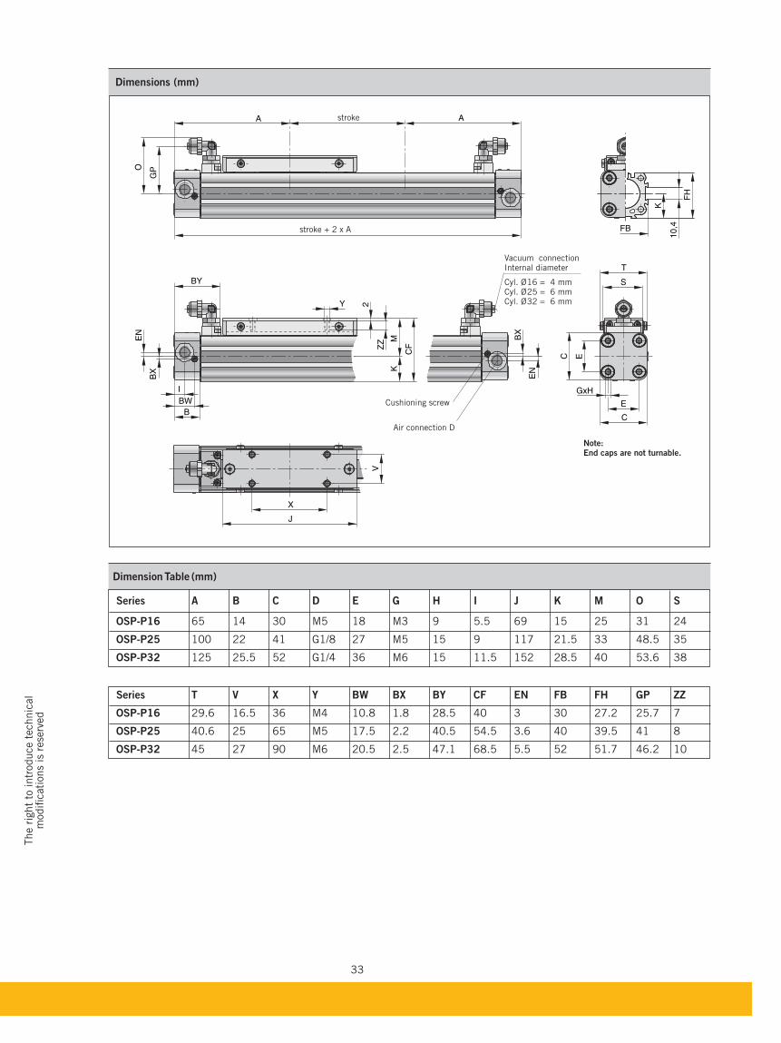
Dimension Table (mm)
OSP-P16 65 14 30 M5 18 M3 9 5.5 69 15 25 31 24
OSP-P25 100 22 41 G1/8 27 M5 15 9 117 21.5 33 48.5 35
OSP-P32 125 25.5 52 G1/4 36 M6 15 11.5 152 28.5 40 53.6 38
OSP-P16 29.6 16.5 36 M4 10.8 1.8 28.5 40 3 30 27.2 25.7 7
OSP-P25 40.6 25 65 M5 17.5 2.2 40.5 54.5 3.6 40 39.5 41 8
OSP-P32 45 27 90 M6 20.5 2.5 47.1 68.5 5.5 52 51.7 46.2 10
A A
GPO
FB
K
FH
10,4
GxH
E
T
EC
C
S
CF
K
EN
BX
M
B
I
BW
BY
Y
ZZ
2
X
V
J
EN
BX
stroke
stroke + 2 x A
Vacuum connectionInternal diameter
Cyl. Ø16 = 4 mmCyl. Ø25 = 6 mmCyl. Ø32 = 6 mm
Cushioning screw
Air connection D
Note:End caps are not turnable.
Dimensions (mm)
34
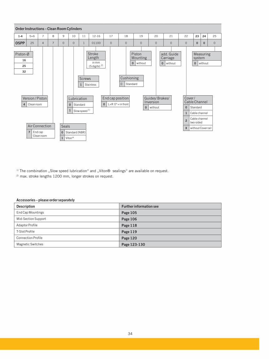
Accessories – please order separately
Description Further information see
End Cap Mountings Page 105
Mid-Section Support Page 106
Adaptor Profile Page 118
T-Slot Profile Page 119
Connection Profile Page 120
Magnetic Switches Page 123-130
Order Instructions – Clean Room Cylinders
1-4 5+6 7 8 9 10 11 12-16 17 18 19 20 21 22 23 24 25
OSPP 25 4 7 0 0 1 01100 0 0 0 0 0 0 0 0 0
Air Connection
7 End cap
Clean room
End cap position
0 L+R 0° = in front
Version / Piston
4 Clean room
Seals
0 Standard (NBR)
1 Viton ®
Lubrication
0 Standard
1 Slow speed 1)
add. Guide Carriage
0 without
Screws
1 Stainless
Cushioning
0 Standard
Piston Mounting
0 without
Guides/ Brakes/ Inversion
0 without
Cover / Cable Channel
0 Standard
1 Cable channel
2Cable channel
two-sided
X without Cover rail
Measuring system
0 without
Stroke Length
in mm
(5 digits) 2)
Piston-Ø
16
25
32
1) The combination „Slow speed lubrication“ and „Viton® sealings“ are available on request.2) max. stroke lengths 1200 mm, longer strokes on request.
35
The r
ight
to intr
oduce t
echnic
al
modifi
cati
ons
is r
ese
rved
For basic cylinder see page 15-24For plain bearing guide SLIDELINE see page 49-50For mountings and accessories see page 101-120
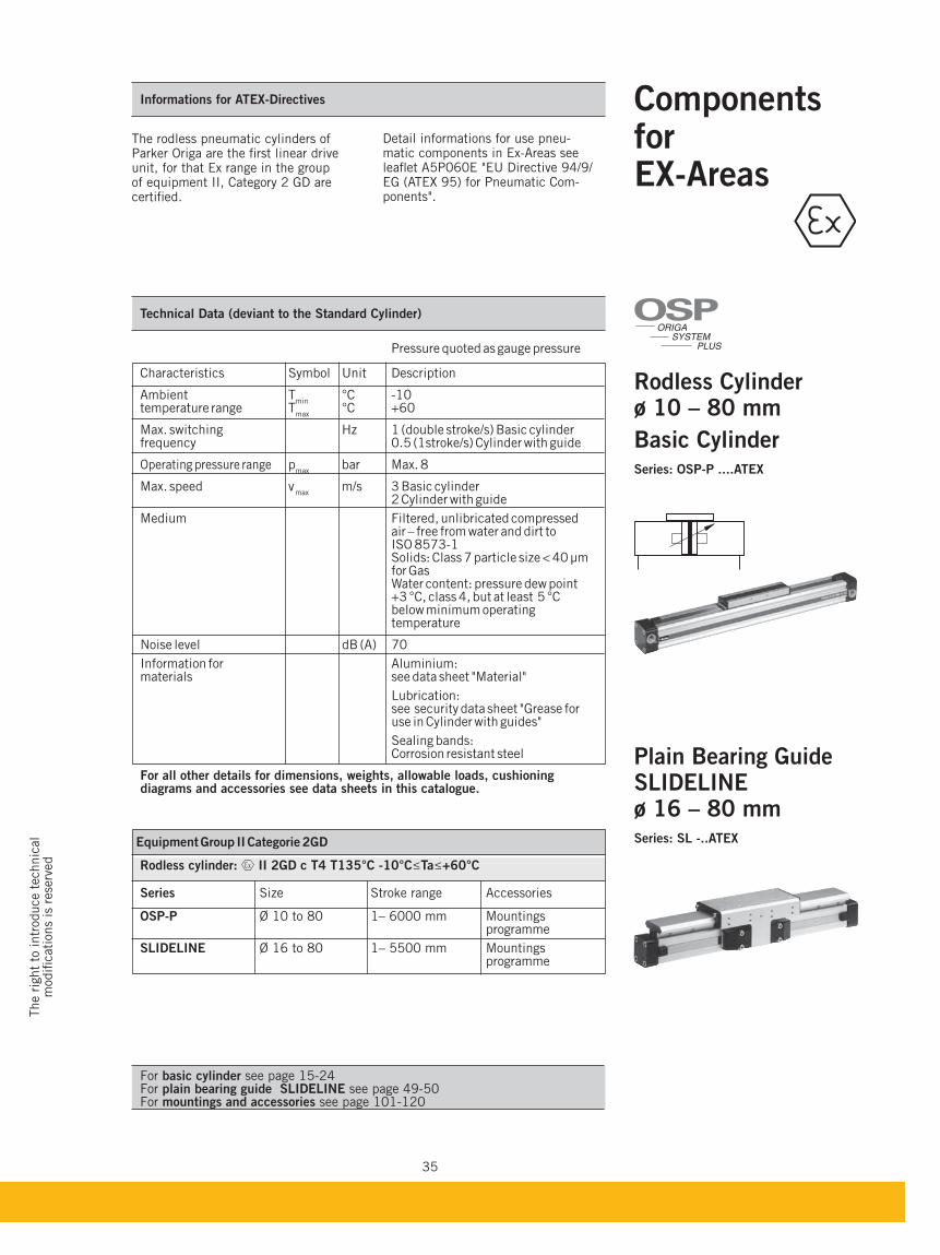
ComponentsforEX-Areas
Rodless Cylinder ø 10 – 80 mm
Series: OSP-P ....ATEX
SLIDELINEø 16 – 80 mmSeries: SL -..ATEX
Informations for ATEX-Directives
Detail informations for use pneu-matic components in Ex-Areas see leaflet A5P060E "EU Directive 94/9/EG (ATEX 95) for Pneumatic Com-ponents".
Technical Data (deviant to the Standard Cylinder)
Pressure quoted as gauge pressure
Characteristics Symbol Unit Description
Ambient Tmin
°C -10 temperature range T
max °C +60
Max. switching Hz 1 (double stroke/s) Basic cylinder frequency 0.5 (1stroke/s) Cylinder with guide
Operating pressure range pmax
bar Max. 8 Max. speed v
max m/s 3 Basic cylinder
2 Cylinder with guide
Medium Filtered, unlibricated compressed air – free from water and dirt to ISO 8573-1 Solids: Class 7 particle size < 40 µm for Gas Water content: pressure dew point +3 °C, class 4, but at least 5 °C below minimum operating temperature
Noise level dB (A) 70
Information for Aluminium: materials see data sheet "Material"
Lubrication: see security data sheet "Grease for use in Cylinder with guides"
Sealing bands: Corrosion resistant steel
For all other details for dimensions, weights, allowable loads, cushioning diagrams and accessories see data sheets in this catalogue.
Equipment Group II Categorie 2GD
Rodless cylinder: II 2GD c T4 T135°C -10°C Ta +60°C
Series Size Stroke range Accessories
OSP-P Ø 10 to 80 1– 6000 mm Mountings programme
SLIDELINE Ø 16 to 80 1– 5500 mm Mountings programme
The rodless pneumatic cylinders of Parker Origa are the first linear drive unit, for that Ex range in the group of equipment II, Category 2 GD are certified.
ORIGA
SYSTEM
PLUS
OSP
36
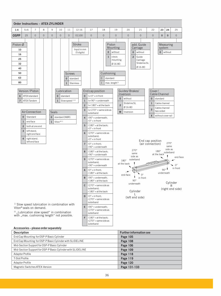
Order Instructions – ATEX-ZYLINDER
1-4 5+6 7 8 9 10 11 12-16 17 18 19 20 21 22 23 24 25
OSPP 25 0 0 0 0 0 01100 0 0 0 0 0 0 0 0 0
Air Connection
0 Standard
1 end face
2 both at one end
3 left stand.
right end face
4 right stand.
left end face
Version / Piston
6 ATEX standard
7 ATEX Tandem
Seals
0 standard (NBR)
1 Viton ® 1)
Lubrication
0 standard
1 Slow speed 1) 2)
add. Guide Carriage
0 without
2 Guide
Carriage
Slideline SL
Ø 16-80
Screws
0 standard
1 Stainless
Cushioning
0 standard
1 max. length 2)
Piston Mounting
0 without
1 clevis
mounting
Ø 16-80
Guides/ Brakes/ Inversion
0 without
2Slideline SL
Ø 16-80
M Inversion
Measuring system
0 without
Stroke
Input in mm
(5 digits)
Piston-Ø
10
16
25
32
40
50
63
80
1) Slow speed lubrication in combination with Viton® seals on demand.2) „Lubrication slow speed“ in combination with „max. cushioning length“ not possible.
End cap position
0 l+r 0° = in front
1 l+r 90° = underneath
2 l+r 180° = at the back
3 l+r 270° = same side as
outerband
4 l 90° = underneath;
r 0° = in front
5 l 180° = at the back;
r 0° = in front
6 l 270° = same side as
outerband;
r 0° = in front
7 l 0° = in front;
r 90° = underneath
8 l 180° = at the back;
r 90° = underneath
9 l 270° = same side as
outerband;
r 90° = underneath
A l 0° = in front;
r 180° = at the back
l 90° = underneath;
r 180° = at the back
C l 270° = same side as
outerband;
r 180° = at the back
D l 0° = in front;
r 270° = same side as
outerband
E l 90° = underneath;
r 270° = same side as
outerband
F l 180° = at the back;
r 270° = same side as
outerband
Cover / Cable Channel
0 standard
1 Cable channel
2Cable channel
two-sided
X without cover rail
270°
same
side as
outerband
270°
same
side as
outerband
0°
in front
0°
in front
180°
at the back
180°
at the back
90°
underneath
90°
underneath
end-face
end-face
End cap position (air connection)
Cylinder L
(left end side)
Cylinder R
(right end side)
Accessories – please order separately
Description Further information see
End Cap Mounting for OSP-P Basic Cylinder Page 105
End Cap Mounting for OSP-P Basic Cylinder with SLIDELINE Page 108
Mid-Section Support for OSP-P Basic Cylinder Page 106
Mid-Section Support for OSP-P Basic Cylinder with SLIDELINE Page 109
Adaptor Profile Page 118
T-Slot Profile Page 119
Adaptor Profile Page 120
Magnetic Switches ATEX-Version Page 131-133
37
The r
ight
to intr
oduce t
echnic
al
modifi
cati
ons
is r
ese
rved
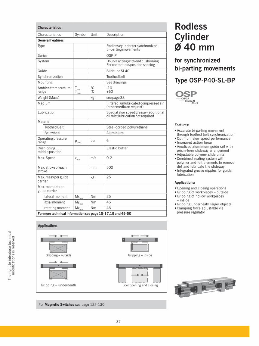
Characteristics
Characteristics Symbol Unit Description
General Features
Type Rodless cylinder for synchronized bi-parting movements
Series OSP-P
System Double acting with end cushioning For contactless position sensing
Guide Slideline SL40
Synchronization Toothed belt
Mounting See drawings
Ambient temperaturerange
Tmin
Tmax
°C°C
-10+60
Weight (Mass) kg see page 38
Medium Filtered, unlubricated compressed air (other media on request)
Lubrication Special slow speed grease – additional oil mist lubrication not required
Material
Toothed Belt Steel-corded polyurethane
Belt wheel Aluminium
Operating pressure range p
maxbar 6
Cushioning middle position
Elastic buffer
Max. Speed vmax
m/s 0.2
Max. stroke of each stroke
mm 500
Max. mass per guide carrier
kg 25
Max. moments on guide carrier
lateral moment Mxmax
Nm 25
axial moment Mymax
Nm 46
rotating moment Mzmax
Nm 46
For more technical information see page 15-17,19 and 49-50
Rodless Cylinder Ø 40 mm
for synchronized
bi-parting movements
Features:
through toothed belt synchronization
prism-form slideway arrangement
polymer and felt elements to remove dirt and lubricate the slideway
lubrication
Applications:
– inside
pressure regulator
ORIGA
SYSTEM
PLUS
OSP
For Magnetic Switches see page 123-130
Applications
Gripping – outside Gripping – inside
Gripping – underneath Door opening and closing
38
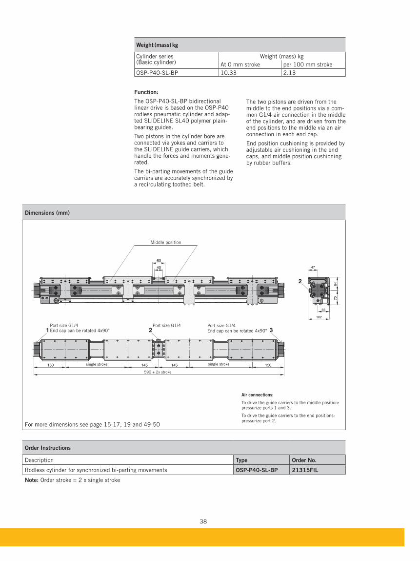
Dimensions (mm)
For more dimensions see page 15-17, 19 and 49-50
Order Instructions
Description Type Order No.
Rodless cylinder for synchronized bi-parting movements 21315FIL
Note: Order stroke = 2 x single stroke
150 145 145 150
60
40
1 2 3
47
55
102
70
642
Port size G1/4End cap can be rotated 4x90°
Port size G1/4 Port size G1/4End cap can be rotated 4x90°
Air connections:
To drive the guide carriers to the middle position:pressurize ports 1 and 3.
To drive the guide carriers to the end positions:pressurize port 2.
single strokesingle stroke
590 + 2x stroke
Function:
The OSP-P40-SL-BP bidirectional linear drive is based on the OSP-P40 rodless pneumatic cylinder and adap-ted SLIDELINE SL40 polymer plain-bearing guides.
Two pistons in the cylinder bore are connected via yokes and carriers to the SLIDELINE guide carriers, which handle the forces and moments gene-rated.
The bi-parting movements of the guide carriers are accurately synchronized by a recirculating toothed belt.
The two pistons are driven from the middle to the end positions via a com-mon G1/4 air connection in the middle of the cylinder, and are driven from the end positions to the middle via an air connection in each end cap.
End position cushioning is provided by adjustable air cushioning in the end caps, and middle position cushioning by rubber buffers.
Weight (mass) kg
Cylinder series(Basic cylinder)
Weight (mass) kg
At 0 mm stroke per 100 mm stroke
OSP-P40-SL-BP 10.33 2.13
Middle position
39
The r
ight
to intr
oduce t
echnic
al
modifi
cati
ons
is r
ese
rved
For Magnetic Switches see page 127-130
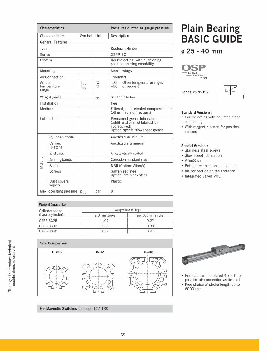
ø 25 - 40 mm
Standard Versions:
Double-acting with adjustable end
cushioning
With magnetic piston for position
sensing
Special Versions:
Stainless steel screws
Slow speed lubrication
Viton® seals
Both air connections on one end
Air connection on the end-face
Integrated Valves VOE
Weight (mass) kg
Cylinder series (basic cylinder)
Weight (mass) [kg]
at 0 mm stroke per 100 mm stroke
OSPP-BG25 1.09 0.22
OSPP-BG32 2.26 0.38
OSPP-BG40 3.52 0.41
Size Comparison
Characteristics Pressures quoted as gauge pressure
Characteristics Symbol Unit Description
General Features
Type Rodless cylinder
Series OSPP-BG
System Double-acting, with cushioning, position sensing capability
Mounting See drawings
Air Connection Threaded
Ambient Tmin
°C -10 - Other temperature ranges temperature T
max °C +80 on request
range
Weight (mass) kg See table below
Installation free
Medium Filtered, unlubricated compressed air (other media on request) Lubrication Permanent grease lubrication (additional oil mist lubrication not required) Option: special slow speed grease
Cylinder Profile Anodized aluminium
Carrier, Anodized aluminium (piston)
End caps Al, catalytically coated
Sealing bands Corrosion resistant steel
Seals NBR (Option: Viton®)
Screws Galvanized steel Option: stainless steel
Dust covers, Plastic wipers
Max. operating pressure pmax
bar 8
Mate
rial
ORIGA
SYSTEM
PLUS
OSP
End cap can be rotated 4 x 90° to position air connection as desired
Free choice of stroke length up to 6000 mm
40
Mountings see page 44
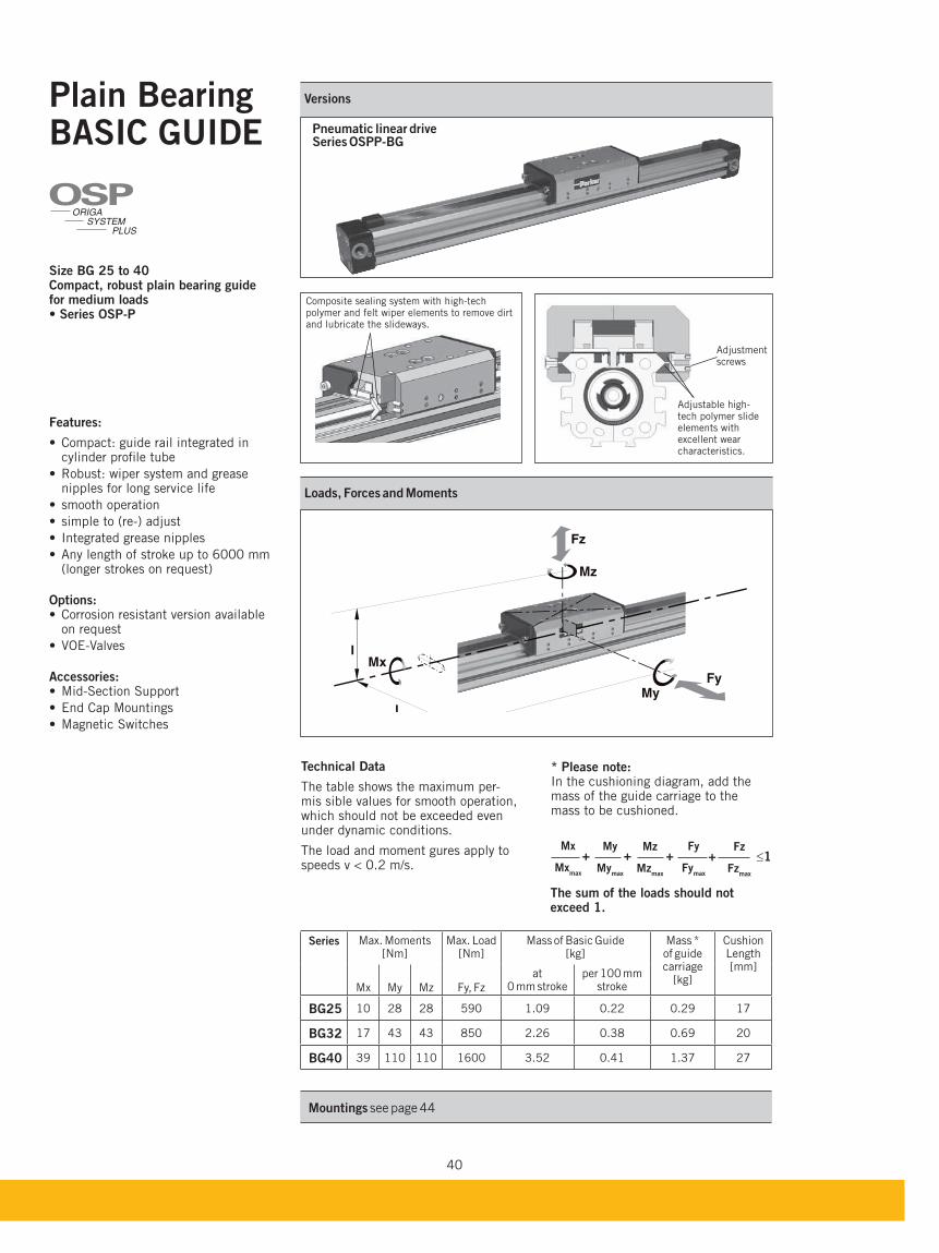
Pneumatic linear drive
Versions
Technical Data
The table shows the maximum per-mis sible values for smooth operation, which should not be exceeded even under dynamic conditions.
The load and moment gures apply to speeds v < 0.2 m/s.
Loads, Forces and Moments
ORIGA
SYSTEM
PLUS
OSP
* Please note:In the cushioning diagram, add the mass of the guide carriage to the mass to be cushioned.
1Mz
Mzmax
Fz
Fzmax
Mx
Mxmax
My
Mymax
Fy
Fymax
+ + + +
Compact, robust plain bearing guide for medium loads
Features:
Compact: guide rail integrated in cylinder profile tube
Robust: wiper system and grease nipples for long service life
smooth operation
simple to (re-) adjust
Integrated grease nipples
Any length of stroke up to 6000 mm (longer strokes on request)
Options:Corrosion resistant version available on request
VOE-Valves
Accessories: Mid-Section Support
End Cap Mountings
Magnetic Switches
Series Max. Moments[Nm]
Max. Load [Nm]
Mass of Basic Guide [kg]
Mass * of guide carriage
[kg]
CushionLength[mm]
Mx My Mz Fy, Fz
at 0 mm stroke
per 100 mm stroke
10 28 28 590 1.09 0.22 0.29 17
17 43 43 850 2.26 0.38 0.69 20
39 110 110 1600 3.52 0.41 1.37 27
Composite sealing system with high-tech polymer and felt wiper elements to remove dirt and lubricate the slideways.
Adjustable high-tech polymer slide elements with excellent wear characteristics.
Adjustment screws
The sum of the loads should not exceed 1.
41
The r
ight
to intr
oduce t
echnic
al
modifi
cati
ons
is r
ese
rved
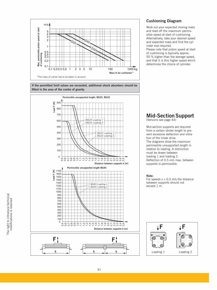
Mid-Section Support(Versions see page 44)
Mid-section supports are required
from a certain stroke length to pre-
vent excessive deflection and vibra-
tion of the linear drive.
The diagrams show the maximum
permissible unsupported length in
relation to loading. A distinction
must be drawn between
loading 1 and loading 2.
Deflection of 0.5 mm max. between
supports is permissible.
Note:For speeds v > 0.5 m/s the distance between supports should not exceed 1 m.
F F
Distance between supports k [m]
Distance between supports k [m]
Load F
[N
]Load F
[N
]
BG25 Loading 1BG25 Loading 2
BG40 Loading 1BG40 Loading 2
Loading 1 Loading 2
F F
Cushioning Diagram
Work out your expected moving mass
and read off the maximum permis-
sible speed at start of cushioning.
Alternatively, take your desired speed
and expected mass and find the cyl-
inder size required.
Please note that piston speed at start
of cushioning is typically approx.
50 % higher than the average speed,
and that it is this higher speed which
determines the choice of cylinder.
*The mass of carrier has to be taken in account.
Max.
perm
issi
ble
pis
ton s
peed a
t st
art
of
cush
ionin
g
Mass to be cushioned *
If the permitted limit values are exceeded, additional shock absorbers should be
fitted in the area of the centre of gravity.
BG32 Loading 1BG32 Loading 2
42
B
BX
EN
BY
BW
I
O
BX
EN K
C E
G x H
C
E
AA
BB
JJDD
GG
FF
FB
Y MCBmaxCAmax
ZZ F
S
FQ
EE
FT
FAEC
KLA
A
A
5,3
10
,4
BY
BW
I
O
EN
BX
BX
EN
C
E
C E
G x HB
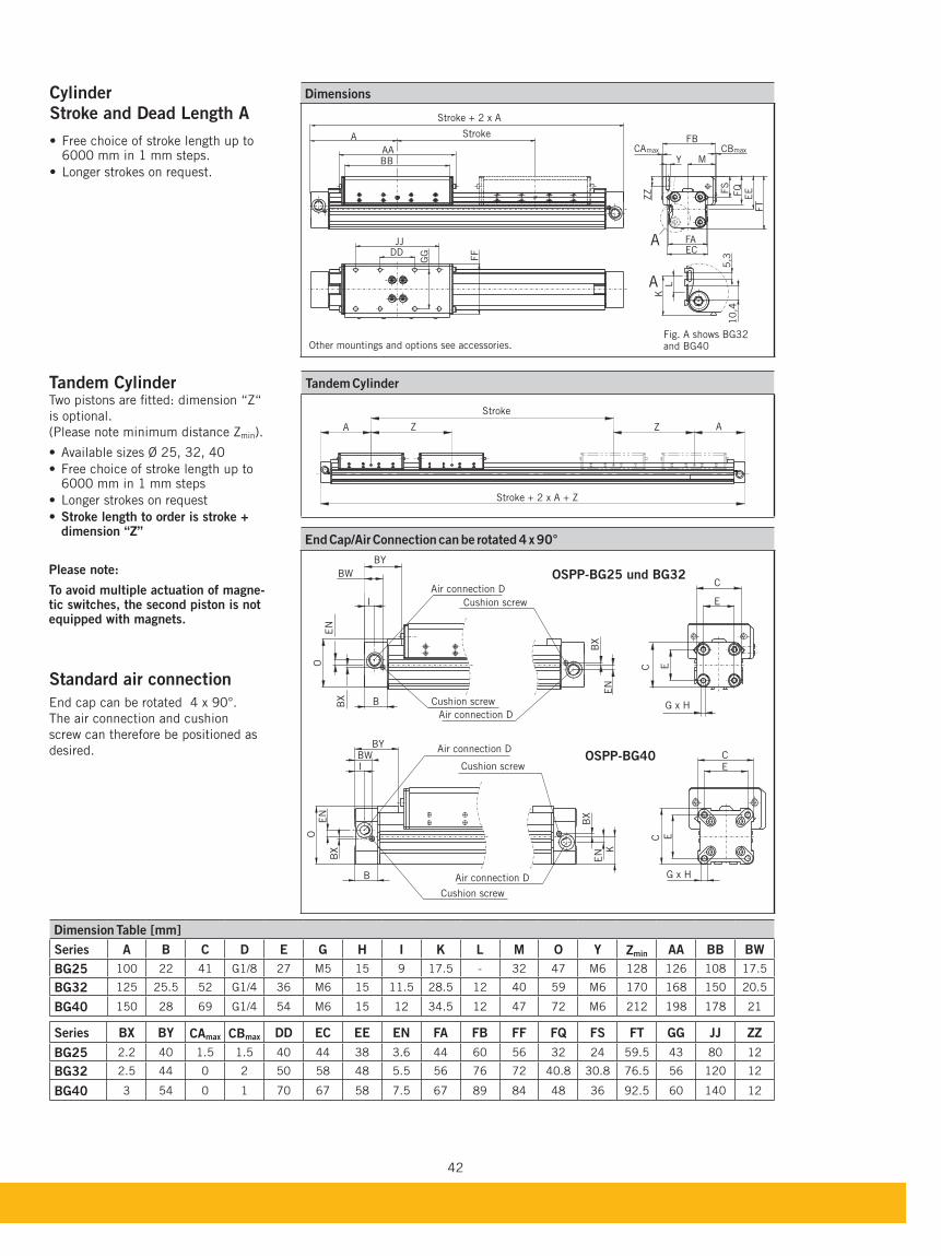
Dimensions
A Z Z A
Stroke
Stroke + 2 x A + Z
Tandem Cylinder
Air connection D
Cushion screw
End Cap/Air Connection can be rotated 4 x 90°
Other mountings and options see accessories.
Stroke + 2 x A
Stroke
CylinderStroke and Dead Length A
Free choice of stroke length up to 6000 mm in 1 mm steps.
Longer strokes on request.
Cushion screw
Cushion screw
Cushion screw
Air connection D
Air connection D
Air connection D
Fig. A shows BG32 and BG40
Tandem CylinderTwo pistons are fitted: dimension “Z“
is optional.
(Please note minimum distance Zmin).
Available sizes Ø 25, 32, 40
Free choice of stroke length up to 6000 mm in 1 mm steps
Longer strokes on request
Stroke length to order is stroke + dimension “Z”
Please note:
To avoid multiple actuation of magne-tic switches, the second piston is not equipped with magnets.
Standard air connection
End cap can be rotated 4 x 90°.
The air connection and cushion
screw can therefore be positioned as
desired.
Dimension Table [mm]
Series A C D E G H I K L M O Y Zmin AA
100 22 41 G1/8 27 M5 15 9 17.5 - 32 47 M6 128 126 108 17.5
125 25.5 52 G1/4 36 M6 15 11.5 28.5 12 40 59 M6 170 168 150 20.5
150 28 69 G1/4 54 M6 15 12 34.5 12 47 72 M6 212 198 178 21
Series CAmax max DD EC EE EN FA FF FQ FS FT GG ZZ
2.2 40 1.5 1.5 40 44 38 3.6 44 60 56 32 24 59.5 43 80 12
2.5 44 0 2 50 58 48 5.5 56 76 72 40.8 30.8 76.5 56 120 12
3 54 0 1 70 67 58 7.5 67 89 84 48 36 92.5 60 140 12
43
The r
ight
to intr
oduce t
echnic
al
modifi
cati
ons
is r
ese
rved
BX
BW
B
BX
C
E
C E
G x H
C
E
G x H
EC
I1
I2
FN
BW
B
C
E
G x H
EC
C
E
G x H
EC
Air connection D
Air connection D
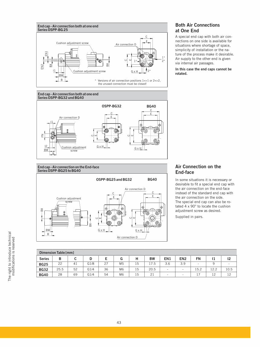
End cap - Air connection on the End-face
Dimension Table [mm]
Series C D E G H EN1 EN2 FN I1 I2
22 41 G1/8 27 M5 15 17.5 3.6 3.9 - 9 -
25.5 52 G1/4 36 M6 15 20.5 - - 15.2 12.2 10.5
28 69 G1/4 54 M6 15 21 - - 17 12 12
at One EndA special end cap with both air con-
nections on one side is available for
situations where shortage of space,
simplicity of installation or the na-
ture of the process make it desirable.
Air supply to the other end is given
via internal air passages.
In this case the end caps cannot be
rotated.
Cushion adjustment screw
Air connection D
End cap - Air connection both at one end
C
E
EC
G x H
1*
2*
2*
BX
B
BW
I1
EN
2
EN
1
BX
1*
End cap - Air connection both at one end
Cushion adjustment screw
Cushion adjustment screw
Cushion adjustment screw
Air connection D
Air Connection on the End-face
In some situations it is necessary or
desirable to fit a special end cap with
the air connection on the end-face
instead of the standard end cap with
the air connection on the side.
The special end cap can also be ro-
tated 4 x 90° to locate the cushion
adjustment screw as desired.
Supplied in pairs.
* Versions of air connection positions 1=>1 or 2=>2, the unused connection must be closed!
44
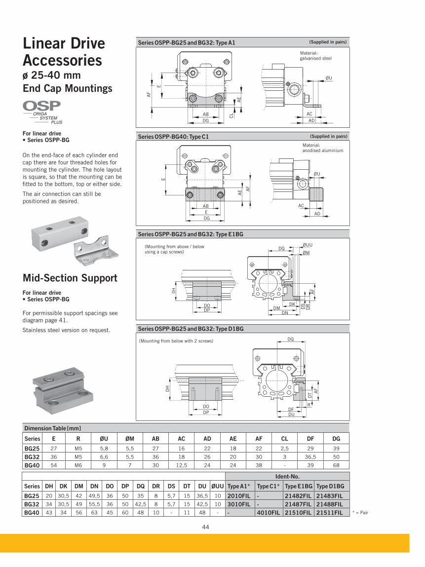
Linear DriveAccessoriesø 25-40 mm
End Cap Mountings
For linear drive
On the end-face of each cylinder end
cap there are four threaded holes for
mounting the cylinder. The hole layout
is square, so that the mounting can be
fitted to the bottom, top or either side.
The air connection can still be
positioned as desired.
ORIGA
SYSTEM
PLUS
OSP
(Mounting from below with 2 screws)
(Mounting from above / below using a cap screws)
Mid-Section Support
For linear drive
For permissible support spacings see
diagram page 41.
Stainless steel version on request.
Material: galvanised steel
Material: anodised aluminium
(Supplied in pairs)
(Supplied in pairs)
* = Pair
Ident-No.
Series DH DK DM DN DO DP DQ DR DS DT DU ØUU Type A1* Type C1*
20 30,5 42 49,5 36 50 35 8 5,7 15 36,5 10 2010FIL - 21482FIL 21483FIL
34 30,5 49 55,5 36 50 42,5 8 5,7 15 42,5 10 3010FIL - 21487FIL 21488FIL
43 34 56 63 45 60 48 10 - 11 48 - - 4010FIL 21510FIL 21511FIL
Dimension Table [mm]
Series E R ØU ØM AC AD AE AF CL DF DG
27 M5 5,8 5,5 27 16 22 18 22 2,5 29 39
36 M5 6,6 5,5 36 18 26 20 30 3 36,5 50
54 M6 9 7 30 12,5 24 24 38 - 39 68
45
The r
ight
to intr
oduce t
echnic
al
modifi
cati
ons
is r
ese
rved
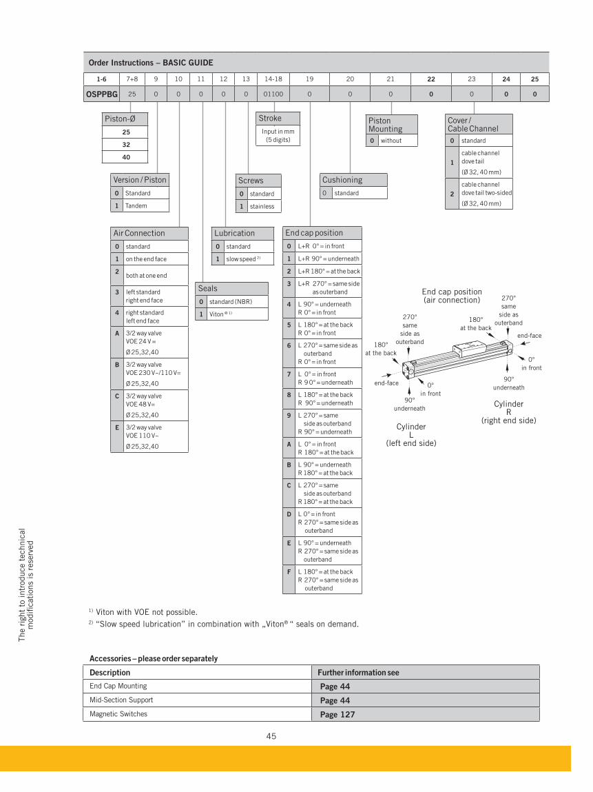
Accessories – please order separately
Description Further information see
End Cap Mounting Page 44
Mid-Section Support Page 44
Magnetic Switches Page 127
Air Connection
0 standard
1 on the end face
2both at one end
3 left standard
right end face
4 right standard
left end face
A 3/2 way valve
VOE 24 V =
Ø 25,32,40
3/2 way valve
VOE 230 V~/110 V=
Ø 25,32,40
C 3/2 way valve
VOE 48 V=
Ø 25,32,40
E 3/2 way valve
VOE 110 V~
Ø 25,32,40
End cap position
0 L+R 0° = in front
1 L+R 90° = underneath
2 L+R 180° = at the back
3 L+R 270° = same side
as outerband
4 L 90° = underneath
R 0° = in front
5 L 180° = at the back
R 0° = in front
6 L 270° = same side as
outerband
R 0° = in front
7 L 0° = in front
R 9 0° = underneath
8 L 180° = at the back
R 90° = underneath
9 L 270° = same
side as outerband
R 90° = underneath
A L 0° = in front
R 180° = at the back
L 90° = underneath
R 180° = at the back
C L 270° = same
side as outerband
R 180° = at the back
D L 0° = in front
R 270° = same side as
outerband
E L 90° = underneath
R 270° = same side as
outerband
F L 180° = at the back
R 270° = same side as
outerband
Version / Piston
0 Standard
1 Tandem
Seals
0 standard (NBR)
1 Viton ® 1)
Lubrication
0 standard
1 slow speed 2)
Screws
0 standard
1 stainless
Cushioning
0 standard
Piston Mounting
0 without
Cover / Cable Channel
0 standard
1
cable channel
dove tail
(Ø 32, 40 mm)
2
cable channel
dove tail two-sided
(Ø 32, 40 mm)
Stroke
Input in mm
(5 digits)
Piston-Ø
25
32
40
1) Viton with VOE not possible.2) “Slow speed lubrication” in combination with „Viton® “ seals on demand.
270°
same
side as
outerband
270°
same
side as
outerband
0°
in front
0°
in front
180°
at the back
180°
at the back
90°
underneath
90°
underneath
end-face
end-face
End cap position (air connection)
Cylinder L
(left end side)
Cylinder R
(right end side)
1-6 7+8 9 10 11 12 13 14-18 19 20 21 22 23 24 25
25 0 0 0 0 0 01100 0 0 0 0 0 0 0
Related Documents