Rod Position Indication Chapter 6.3 Chapter 6.3 B&W Cross-Training Course R-326C

Welcome message from author
This document is posted to help you gain knowledge. Please leave a comment to let me know what you think about it! Share it to your friends and learn new things together.
Transcript
Rod Position Indication
Chapter 6.3Chapter 6.3B&W Cross-Training Course
R-326C

OBJECTIVES1. State the purposes of the control rod position
indication systems.
2. Explain the two methods used to determine control rod position.
3. Explain how the two rod position indication
2
systems are used in the following:
a) Asymmetric rod determination
b) In, out limits
c) Regulating group sequence enabling
d) Inhibit circuits
e) Sequence monitoring

Rod Position Indication• Two methods:
o Absolute Position Indication (API)Actual position of leadscrew.
Magnet on torque taker.
Reed switches in Position Indicator Assembly.– Attached to motor tube assembly.Attached to motor tube assembly.
o Relative Position Indication (RPI)Monitors command signals to CRDM.
Demanded position of rod.

ReedSwitches
4
SwitchesFig. 6.3-1

Absolute PositionIndication (API) –
5
Indication (API) Two-Channel Avg.
Fig. 6.3-2

Absolute PositionIndication (API) –
6
Indication (API) Four-Channel Avg.
Fig. 6.3-3

Absolute Position Indication (1)
• Four channel averaging circuit.o 72 reed switches: 4 separate, isolable channels.
Reed Switches are 2 inches apart (0 – 100% indication).
o Reed switches close by magnet in 3-2-3-2 sequence.
o If 1 s itch fails openo If 1 switch fails open:Slight loss of accuracy.
No asymmetric rod condition.
o If 2 adjacent switches fail open:Asymmetric rod condition.

Absolute Position Indication (2)
• Output from each channel sent to amplifier.o Indicates on Position Indication Panel.
o Other uses for signal.
• 5 Zone References Switches:o 0%, 25%, 50%, 75%, 100%.
Not simulated at TTC.
• 4 Limit Switcheso 2 In Limit and 2 Out Limit switches.
o Switches are 1.5 inches beyond 0% & 100% zone reference switches.

Relative Position Indication• Monitors command signals to CRDM.
• Indicates demanded position of rod.
• Pulse stepping motor turns as phases are energized.
• RPI will not show correct position if rod:o Tripped
o Dropped
o Stuck
• Output on Position Indication Panel.
• RPI signal also used for Sequential Fault Logic.

RelativePosition Indicator
10
Position IndicatorFig. 6.3-4

11Position Indication Panel (Fig. 6.3-5)
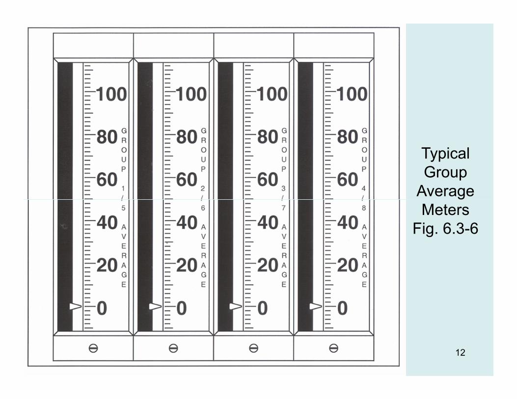
TypicalGroup
Average
12
MetersFig. 6.3-6

13Inhibit Logic (Fig. 6.3-7)
In Inhibit & Out Inhibit Logic• Prevents additional commands from reaching
the programmers when rods are full in/out.
• Out Inhibit:o First rod in group to reach Out Limit switch stops
outward rod motion for rest of group.
o Out Limit light on Diamond for individual groups.Out Limit part of auto rod control.
o Other signals, including Asymmetric Fault, will produce Out Inhibit signal.

15Sequence Enable Logic (Fig. 6.3-8)

Out InhibitLogic
16
LogicFig. 6.3-9

17
Sequence Fault Logic (Fig. 6.3-10)

In Inhibit & Out Inhibit Logic• In Inhibit:
o First rod in group to reach In Limit switch stops inward rod motion for rest of group.
o In Limit light on Diamond for individual groups.
o In Limit Bypass P/B on Diamond.All G 1 7 t b i t d b l I Li it fAllows Groups 1 -7 to be inserted below In Limit for latching.
o If Asymmetric Fault exists, the In Inhibit is auto bypassed to allow runback, if needed.

Sequence Logic
• Sequence enable logic develops sequence and overlap for moving regulating rods.o Uses API Group Average.
o Ensures 25% overlap.
• Sequence fault logic checks for too much overlap of regulating rodsregulating rods.o Rods move too soon.
o Reactivity addition rate very high.
o Uses RPI Group Average.
o Prevents auto rod control. Diamond in manual.
Related Documents