Rocky Mountain Power 2011 Clinic Project Dynamic Line Rating Preliminary Design Review Project Advisor: Dr. Thomas Schmid Clinic Team Members: Skyler Kershner, Benjamin Sondelski, Trevor Nichols, Shayan Barzagari, Zhao Qi

Rocky Mountain Power 2011 Clinic Project Dynamic Line Rating Preliminary Design Review Project Advisor: Dr. Thomas Schmid Clinic Team Members: Skyler Kershner,
Dec 20, 2015
Welcome message from author
This document is posted to help you gain knowledge. Please leave a comment to let me know what you think about it! Share it to your friends and learn new things together.
Transcript

Rocky Mountain Power 2011 Clinic Project
Dynamic Line RatingPreliminary Design Review
Project Advisor: Dr. Thomas SchmidClinic Team Members: Skyler Kershner, Benjamin Sondelski, Trevor Nichols, Shayan Barzagari, Zhao Qi

2
Presentation Overview
• Project Background
• Goals
• Proposed Solution
• Additional Considerations
• System Implementation
• Model
• Expected Results
• Budget / Timeline

3
Project Background
• Overhead Conductor Sag
• National Electrical Safety Code specifies minimum clearance
• As conductor heats, sag increases
• Environmental, power considerations
• Dynamic line rating system needed
[1] Clearance Levels

4
Project Goals
• Develop dynamic line rating system
– Combine best characteristics of commercially available models
– Simple design
• Implement system in a model
• Validate collected data
[2] Line Sag Illustration
5
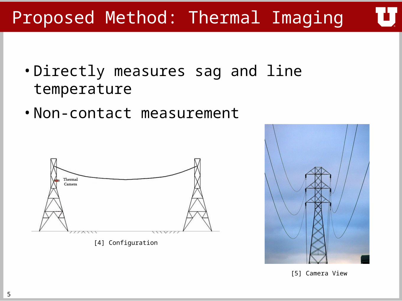
Proposed Method: Thermal Imaging
• Directly measures sag and line temperature
• Non-contact measurement
[4] Configuration
[5] Camera View

6
Proposed Method: Thermal Imaging
• Provides high contrast images, temperature measurement
• Image processing tracks lowest point in line
[6] Thermal Image

7
Proposed Method: Thermal Imaging
• Limitation: Cost
Model Price
FLIR T620 $19,500
FLIR SC325 $13,500
FLIR E60 $7,500
[7]
[8]
[9]

8
Conclusion
• Need for dynamic line rating
• Goals
• Thermal imaging as potential solution
• Limitations of thermal imaging
–Other methods needed

9
Overview
• Sag – Tension rating and calculation
• Tension as a solution
• Tension as a problem
• Design Problems/Solutions**
• Conclusion

10
Tension as a Possible Solution
• All-Inclusive Measurement–line temperature, environment temperature, solar
absorption
• Accuracy
• Simplicity
• Low-Power Draw

11
•
D – Vertical sag
S – Horizontal length of the span
W – Unit weight of the conductor
Tr – Resultant conductor tension
Th – Horizontal component of tension
Fig. 1 Parabolic Sag Curve
Sag-Tension Rating and Calculations
[10]

12
Tension as a Possible Problem
• Cost
• Actual implementation– Required line outage for installation
• Ice and wind loading
• Length of Conductor–Stretching and high temperatures

13
Design Problems/Solutions
• Ice loading
• Wind loading
For structures below 60 feet:
For structures exceed 60 feet:
• Resultant ice and wind loading

14
Conclusion
• Overview of Tension
• Tension pros
• Tension cons
• Solutions to tension cons

15
Overview
• Magnetic Field Sensing
• Implementation difficulties
• Build a model - advantages
• Conclusion

16
Magnetic Field Sensor
Three Axis Magnetic Field Sensor
MAGNETOMETER RS232 W/CASE
• High Accuracy, <0.5% Full Scale• 10 to 154 Sample/Sec• Low Power consumption• Input voltage range 6 to 15 (VDC)
[11]

17
Magnetic Field Measurement Difficulties
18
Build a Model
• Test wide range of aspects
• Control experiment variables and environment
• Develop realistically implementable solutions
• Retain a low budget
19
Conclusion
• Magnetic Sensing
• Magnetic Difficulties
• Advantages of Model

20
Overview
• Proposed Solution
• Math defining model requirements
• Measuring Temperature
• Conclusion

21
Proposed Solution
• Mock thermal imaging system
[12] [13]
• Build a model scaled down to 1:30 ratioApproximately 600 feet scaled to 20 feet
• Measure sag in a controlled environmentClinic Lab – Merrill Engineering Building 2350
• Develop an effective dynamic line rating system

22
Math defining model
• Tension in the line – direct effect of line temperature
• Temperature – direct effect of amount of line current
• Amperage – controlled system input

23
MEASURING TEMPRATURE

24
MEASURING TEMPRATURE

25
Conclusion
• Proposed Solution
• Characteristics of model
• Mock thermal imaging–IR thermometer–IR video camera

Physical Model: Introduction
• benefits of in-house scale model
• power supply
• electrical diagram
• conductor span
• expected model performance
26

27
Benefits of In-House Scale Model
• communications
• controlled environment–simple comparison to IEEE
738–no exposure to weather
• verification of thermal time constant
• test bed for future clinics

28
Power Supply
• need 480V, 3 phase
• 208V 3 phase is available
• 2kVA each
• power supply losses

29
Model Electrical Diagram
National Electrical Code:
• bonding and grounding
• conductor sizing
• overcurrent protection
• ground detector

30
Conductor Span
• 1½″ PVC structure (FORMUFIT connectors)
• transparent covering (acrylic or polycarbonate)
• dead-end attachments

31
Expected Model Performance
• 20′ span
• 200lbs tension at 25°C
• Sparrow ACSR

Physical Model: Conclusion
• benefits of in-house scale model
• power supply
• electrical diagram
• conductor span
• expected model performance
32

33
Budget
Qty Description Cost Total
1 Transformer $0 $0
2 Cable $0 $0
2 Transformer Pad $20 $40
4 Various lugs, clamps, connectors
$20 $80
1 Circuit breaker $300 $300
3 Locking plug $42 $126
1 Tension meter $1000 $1000
Total: $1566

34
Timeline

35
CONCLUSION
• Measure Sag
• Build a Model
• Desirable:
• Measure Conductor Temperature
• Due to budget, use Temp Sensor and IR
Camera
• Validate Measurement
• Measuring Tension
• Magnetic Sensor

36
Contact Info / References
References[1] “Clearance Levels”, Oct. 3, 2011. [Online]. Available: http://www.pge.com/mybusiness/customerservice/otherrequests/treetrimming/faq/orchard/index.shtml.
[2] “Line Sag Illustration”, Oct. 3, 2011. [Online]. Available: http://redefinescience.blogspot.com/2011/05/power-lines.html.
[3] “Tension Illustration”, Oct. 3, 2011. [Online]. Available: http://www.ehow.com/how_8049821_calculate-transmission-line-tension.html.
[4] “Configuration”, Oct. 3, 2011. [Online]. Available: http://www.eng-tips.com/viewthread.cfm?qid=139418&page=274.
[5] ”Power Line View”, Oct. 3, 2011. [Online]. Available: http://forcechange.com/2190/proposed-legislation-would-speed-up-permitting-process-for-transmission-lines.
[6] “Thermal Image”, Oct. 3, 2011. [Online]. Available: http://www.x20.org/thermal/.
[7] “FLIR T620”, Oct. 3, 2011. [Online]. Available: http://www.flir.com/thermography/americas/us/content/?id=18118.
[8] “FLIR SC325”, Oct. 3, 2011. [Online]. Available: http://www.flir.com/thermography/americas/us/content/?id=31095.
[9] “FLIR E60”, Oct. 3, 2011. [Online]. Available: http://www.flir.com/thermography/americas/us/content/?id=36820.
[10] “Sag and Tension”, Sep. 20, 2011. [Online]. Available: http://www.iaei.org/magazine/2004/05/the-effects-of-ruling-span-on-sag-and-tension/
[11] “Smart Digital Magnetometer HMR2300”, Sep. 30, 2011. [Online]. Available: http://www51.honeywell.com/aero/common/documents/myaerospacecatalog-documents/Missiles-Munitions/HMR2300.pdf.
[12] “IR Thermo Gun”, Sep. 29, 2011. [Online]. Available: http://chaermai.en.ecplaza.net/2.asp.
[13] “IR Security Camera”, Sep. 29, 2011. [Online]. Available: http://www.buy.com/retail/product.asp?sku=224174617&listingid=157870950&&
Rocky Mountain Power Clinic TeamUniversity of UtahElectrical and Computer Engineering [email protected]
Related Documents