Rock Structure and Fault Activity chapter 9

Rock Structure and Fault Activity chapter 9. What is structural geology The study of the forms of the Earth’s crust and the processes which have shaped.
Dec 16, 2015
Welcome message from author
This document is posted to help you gain knowledge. Please leave a comment to let me know what you think about it! Share it to your friends and learn new things together.
Transcript

Rock Structure and Fault Activity
chapter 9

What is structural geology
The study of the forms of the Earth’s crust and the processes which have shaped it
• analysis of displacement and changes in shape of rock bodies (strain)
• reconstruct stress that produced strain
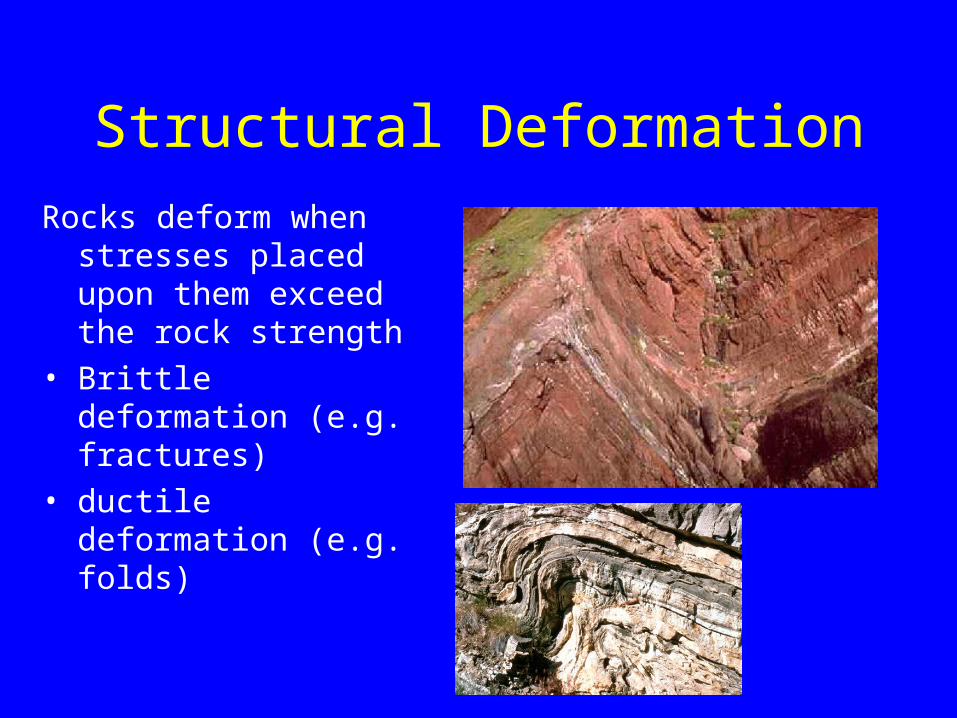
Structural DeformationRocks deform when
stresses placed upon them exceed the rock strength
• Brittle deformation (e.g. fractures)
• ductile deformation (e.g. folds)

Driving Forces• Plate tectonics – plate convergence and ridge
spreading• Deep burial of sediments• Forceful intrusion of magma into the crust• Meteorite impacts

Evidence of Crustal Deformation
• Folding of strata• Faulting of strata• Tilting of strata• Joints and fractures

Evidence of Crustal Deformation
• Folding of strata• Faulting of strata• Tilting of strata• Joints and fractures

Evidence of Crustal Deformation
• Folding of strata• Faulting of strata• Tilting of strata• Joints and fractures

Evidence of Crustal Deformation
• Folding of strata• Faulting of strata• Tilting of strata• Joints and fractures

Applications of structural geology
• subsurface exploration for oil and gas
• mining exploration• geotechnical investigations• groundwater and environmental
site assessment

Geological structures
• Geologic bed contacts• Primary sedimentary structures• Primary igneous structures• Secondary structures

Fundamental Structures
Three fundamental types of geologic structures:
• bed contacts• primary structures - produced during
depositionor emplacement of rock body• secondary structures - produced by
deformationand other process after rock is emplaced

Bed Contacts
Boundaries which separate one rock unit from another
• two types:1. Normal conformable contacts2. Unconformable contacts
(‘unconformities’)

Conformable Bed Contacts
Horizontal contact between rock units with no break in deposition or erosional gaps
• no significant gaps in geologic time
Book Cliffs, central Utah

Unconformable Contacts
Erosion surfaces representing a significant break in deposition (and geologic time)
• angular unconformity• disconformity• non-conformity

Angular UnconformityBedding contact which discordantly cuts
across older strata• discordance means strata are at an angle to
each other• commonly contact is erosion surface

Formation of an angular unconformity

DisconformityErosional gap between rock units
without angular discordance• example: fluvial channel cutting
into underlying sequence of horizontally bedded deposits
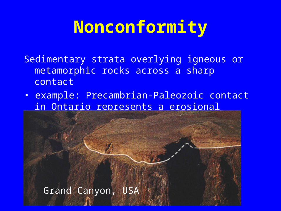
Nonconformity
Sedimentary strata overlying igneous or metamorphic rocks across a sharp contact
• example: Precambrian-Paleozoic contact in Ontario represents a erosional hiatus of about 500 ma
Grand Canyon, USA

Structural Relations
The structural relations between bed contacts are important in determining:1. presence of tectonic
deformation/uplift and;2. relative ages of rock units
• principle of original horizontality• principle of cross-cutting• principle of inclusion

Principle of Original Horizontality
Sedimentary rocks are deposited as essentially horizontal layers• exception is cross-bedding (e.g. delta foresets)• dipping sedimentary strata implies tectonic uplift and
tilting or folding of strata

Principle of Cross-cutting
Igneous intrusions and faults are younger than the rocks that they cross-cut
Mafic dike cutting across older sandstones

Cross-cutting Relations
Often several cross-cutting relationships are present
• how many events in this outcrop?

Principle of Inclusion
Fragments of a rock included within a host rock are always older than the host

Fundamental Structures
Three fundamental types of structures:
• bed contacts• primary structures• secondary structures

Primary Sedimentary Structures
Structures acquired during deposition of sedimentary rock unit
Stratification - horizontal bedding is most common structure in sedimentary rocks

Primary Sedimentary Structures
Cross-bedding - inclined stratification recording migration of sand ripples or dunes

Primary Sedimentary Structures
Ripples - undulating bedforms produced by
unidirectional or oscillating (wave) currents

Ripple marks

Primary Sedimentary Structures
Graded bedding - progressive decrease in grain size upward in bed• indicator of upwards direction in deposit• common feature of turbidites

Primary Sedimentary Structures
Mud cracks - cracks produced by dessication of clays/silts during subaerial exposure

Primary Sedimentary Structures
Sole marks - erosional grooves and marks formed by scouring of bed by unidirectional flows
• good indicators of current flow direction

Primary Sedimentary Structures
Fossils – preserved remains of organisms, casts or moulds
• good strain indicators• determine strain from change in shape of fossil• relative change in length of lines/angle
between lines
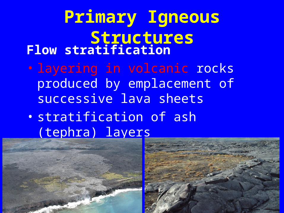
Primary Igneous Structures
Flow stratification • layering in volcanic rocks produced
by emplacement of successive lava sheets
• stratification of ash (tephra) layers

Primary Igneous Structures
Flow stratification • layering in volcanic rocks produced
by emplacement of successive lava sheets
• stratification of ash (tephra) layers

Primary Igneous Structures
Pillow lavas - record extrusion and quenching of lava on sea floor

Importance of Primary Structures
1. Paleocurrents - determine paleoflow directions
2. Origin – mode of deposition, environments3. Way-up - useful indicators of the direction of
younger beds in stratigraphic sequence4. Dating - allow relative ages of rocks to bedetermined based on position, cross-cuttingrelations and inclusions5. Strain indicators - deformation of primarystructures allows estimates of rock strain

Secondary Structures
Secondary structures - deformation structures
produced by tectonic forces and other stresses in crust
Principle types:• fractures/joints• faults/shear zones• folds• cleavage/foliation/lineation

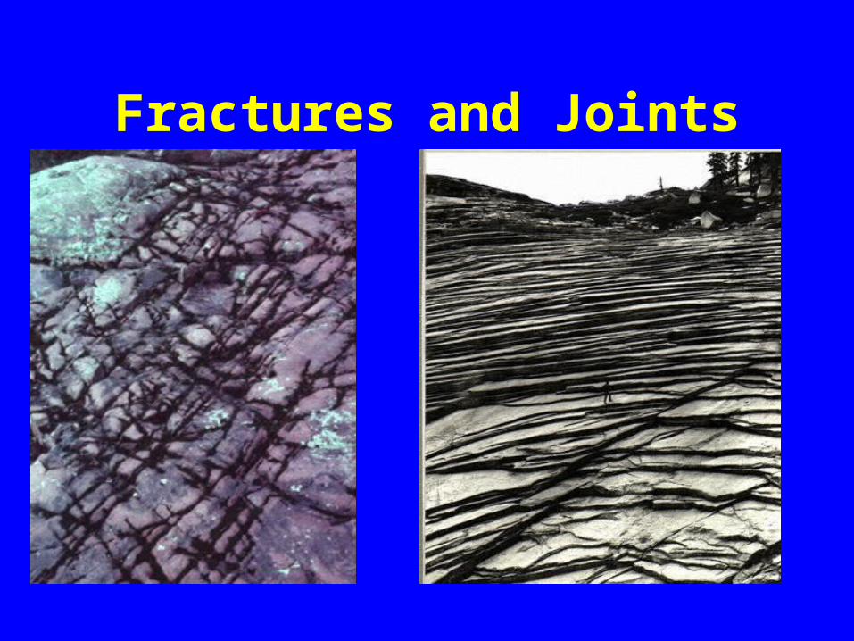
Fractures and Joints
Fractures – surfaces along which rocks have broken and lost cohesion
Joints - fractures with little or no displacement parallel to failure surface
• indicate brittle deformation of rock
Fractures and Joints

FaultsFaults - fracture surfaces with appreciable displacement of strata
• single fault plane
• fault zone - set of associated shear fractures
• shear zone - zone of ductile shearing

Shear Zones
Shear zone - zone of deformed rocks that are more highly strained than surrounding rocks
• common in mid- to lower levels of crust
• shear deformation can be brittle or ductile

Fault Terminology
Hanging wall block- fault block toward which the fault dips
Footwall block - fault block on underside of fault
Fault plane – fault surface
Fault Slip
Slip is the fault displacement described by:• direction of slip• sense of slip• magnitude of slip
Fault Types
Dip-slip faults - slip is parallel to the fault dip directionnormalreversethrust

Fault Types
Normal fault - footwall block dispaced up

Fault Types
Reverse (thrust) fault - footwall block displaced down

Fault Types
Strike-slip – fault slip is horizontal, parallel with strike of the fault plane• right-handed (dextral)• left-handed (sinistral)
Fault Types
Oblique slip – Combination of dip- and strike-slip motion• dextral-normal• dextral-reverse• sinistral-normal• sinistral-reverse

Faults
What type of faults are shown here?

Faults
What type of faults are shown here?

Faults
What type of faults are shown here?

Faults
What type of faults are shown here?

Folds
Folds – warping of strata produced by compressive deformation• range in scale from microscopic
features to regional-scale domes and basins
• indicators of compression and shortening

Fold Terminology
Hinge (Axial) plane - imaginary plane bisecting fold limbs
Hinge line - trace of axial plane on fold crestPlunge - angle of dip of hinge line

horizontal fold axis

plunging fold axis

Fold Terminology
Anticline - convex in direction of youngest beds
Syncline - convex in direction of oldest beds
Antiform - convex upward fold (stratigraphy unknown)
Synform - concave upward fold

Anticline / Antiform?
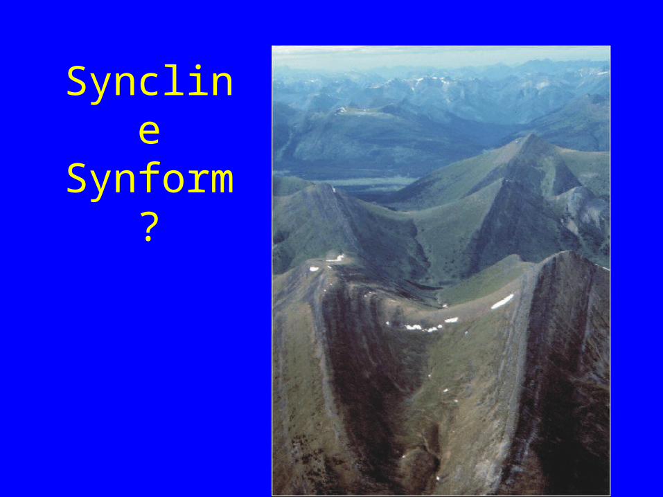
SynclineSynform
?

Fold Terminology
Synformal Anticline - overturned anticline
Antiformal Syncline - overturned syncline

Fold Terminology
Monocline - step-like bend in strata
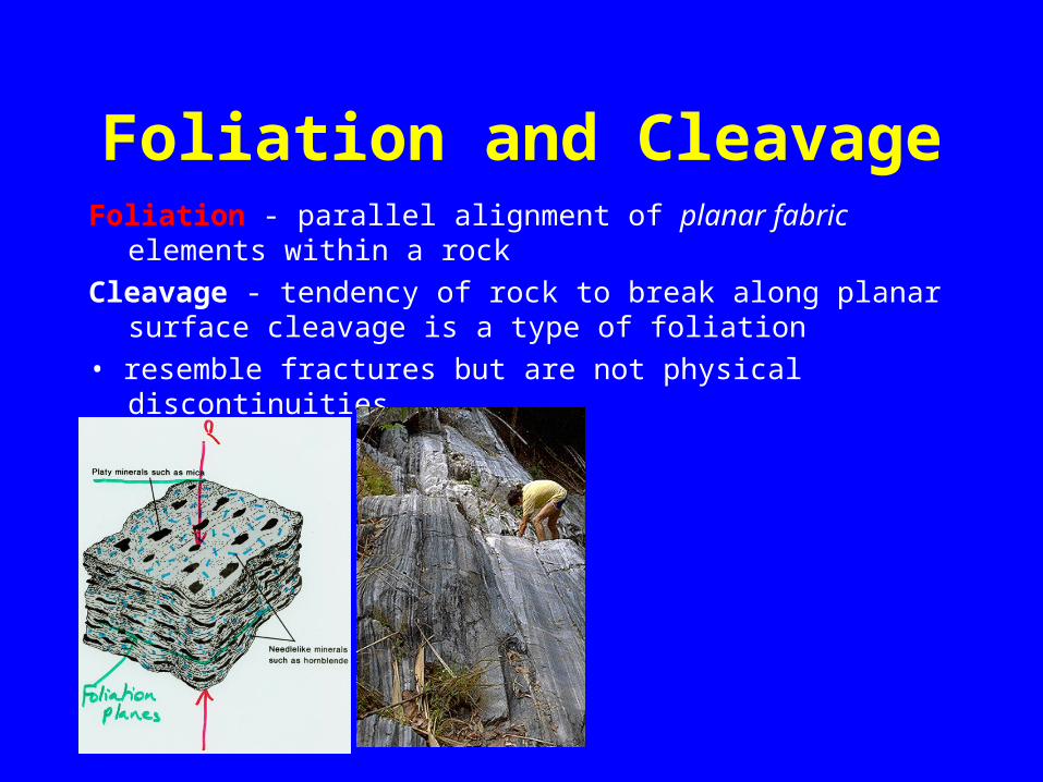
Foliation and CleavageFoliation - parallel alignment of planar fabric elements
within a rockCleavage - tendency of rock to break along planar surface
cleavage is a type of foliation• resemble fractures but are not physical discontinuities

Foliation and CleavageFoliation - parallel alignment of planar fabric elements
within a rockCleavage - tendency of rock to break along planar surface
cleavage is a type of foliation• resemble fractures but are not physical discontinuities

Lineations
Lineation - sub-parallel to parallel alignment of elongate linear fabric elements in a rock body
• e.g. slickenlines and grooves on fault plane surface

Structural analysis
Involves three steps1. Descriptive or geometric analysis2. Kinematic analysis3. Dynamic analysis

Geometrical analysis
Measurement of the 3-dimentional orientation and geometry of geological structures
simplified into:
• lines• planes

lines or linear geological structures
• liniation – any linear feature observed in a rock or
on a rock surface – any imaginary line – such as a fold axis

Orientation of linear structures
LINESTrend – azimuth direction measured clockwise from north 360°Plunge – angle of inclination of line measured from the horizontal (0 - 90°)

Examples of linear structures
• Primary – flute casts, grooves, glacial striae• Secondary – slickenlines, mineral lineations
Glacial striations on bedrock sole marks

Examples of linear structures
• Primary – flute casts, grooves, glacial striae• Secondary – slickenlines, mineral lineations
Grooves on fault plane Slickenlines on fault surface

Orientation of Linear Structures
linear structures on an other planar surface:
• pitch angle– angle from horizontal measured
within the planePitch angleStriations
on a fault plane

Planar Geological Structures
• bedding planes and contacts• foliation• joint surfaces• fault planes• fold limbs• fold axial planes (imaginary
surface)

Examples of Planar Structures
Bedding planes – most common • primary depositional surface• erosional surface
inclined bedding plane

Examples of Planar Structures
Foliation – cleavage planes produced by metamorphism
• common in slates and phyllites
foliated phyllite
Examples of Planar Structures
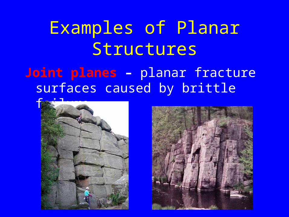
Joint planes – planar fracture surfaces caused by brittle failure

Examples of Planar Structures
Fold axial plane - imaginary plane bisecting limbs of fold

Orientation of Planar Structures
The attitude of a plane can be established from any two lines contained in the plane, provided they are not parallel

Orientation of Planar Structures
Strike – azimuth direction of a horizontal line in a plane
Dip – angle of inclination of line measured from the horizontal (0 - 90°)

Orientation of Planar Structures
Appearent dip– dip measured
along a line other than 90 to strike
– apparent dip will always be less than the true dip angle

Measurement of orientation
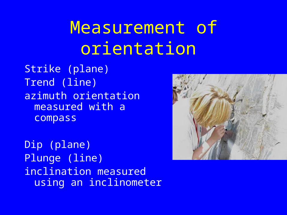
Strike (plane) Trend (line)azimuth orientation measured with a compass
Measurement of orientation
Strike (plane) Trend (line)azimuth orientation
measured with a compass
Dip (plane)Plunge (line)inclination measured
using an inclinometer

Measurement of Strike Direction
Right hand rule???When your thumb (on your right
hand) is pointing in the direction of strike your fingers are pointing in the direction of dip!!

Measure of Dip Angle
The angle between the horizontal and the line or plane

Structural Data
Symbols represent different structural data
Symbols are placed on the map:– in the exact field orientation– where the data is measured

Standard Structural Symboles

Exercises
• geological maps• structure contour and structure
maps• three-point problems• cross sections• sterionets

Geological Maps
• distribution of rock types and contacts– symbols on map represent structures
(strike and dip, fold axes, faults etc.)– map and structure symbols allow you
to infer subsurface structures

Outcrop patterns
Outcrop patterns controlled by attitude (strike and dip) of beds and topographic relief

“V” Rule
• Beds dipping downstream “V” –downstream
• Beds dipping upstream “V” – upstream

Vertical beds cut straight
Vertical oriented beds cut in a straight line regardless of topography!!
Horizontal beds
• layers always at the same altitude – do NOT dip in any direction– layered cake

Outcrop Patterns
Which direction are the beds dipping?

Outcrop Patterns
Which direction are the beds dipping?

Outcrop Patterns
Which direction are the beds dipping?

Outcrop Patterns
Which direction are the beds dipping?

Block models
Relations between outcrop patterns and subsurface structures
map view on bottom – cross sections in blocks on top

Bryce 3-D modeling blocks

Structural Contour Maps
Map showing the relief of a subsurface geological surface– top or bottom of bedding planes,
faults or folded surface– constructed from borehole data

Structure Contour Maps
Structure contour lines are lines of equal elevation• show elevation relative to horizontal datum• values are often negative since subsurface
elevations are commonly below sea level

Datum Surface
Datum is a horizontal reference surface
• regional stratigraphic surface
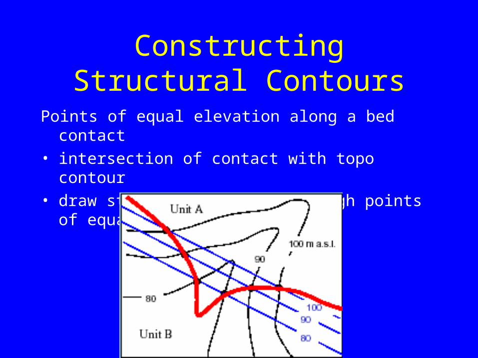
Constructing Structural Contours
Points of equal elevation along a bed contact• intersection of contact with topo contour• draw structure contours through points of
equal elevation

Planar surfaces
Uniformly dipping plane – contours are parallel

folded planar surfaces
Contours have variable spacing

Rules of Contouring
1) contours cannot cross or bi-furcate2) contours cannot end in the middle of
the map, except at a fault or other discontinuity
3) same contour interval must be used across the map and elevations must be labelled
4) elevation is specified relative to datum (e.g. m above sea level)

Determining Dip
Dip direction and angle can be determined from structure conour maps
• measure horizontal separation X and find difference in Z• tan = Z/X, = tan –1 (Z/X)• e.g. = tan –1 (10m/100m), = 6°

Three-point problem
A minimum of three points are required to uniquely define the orientation of a plane

Three-point problem
• Find min and max values
• Draw line between these and divide distance into intervals
• Connect points of equal elevation
• Two points in a plane at the same elevation lie in the line of strike

Three-point problem
• Find min and max values
• Draw line between these and divide distance into intervals
• Connect points of equal elevation
• Two points in a plane at the same elevation lie in the line of strike

Isochore Map
Drill hole logs giving the thicknesses in the drilled (often vertical) direction
Apparent thickness – true thickness = perpendicular to bedding

Isopach Map
Map showing “true” thickness measured perpendicular to bedding

Cross-sections
Cross-section is a 2-D slice through stratigraphy
• construct perpendicular to dip = true dip
• constructed at any other direction = apparent dip

Engineering properties of faulted or folded rock
• shear strength– loose materials– compressive materials– permeable materials

hydrology of fault zones
• water in fault zones common due to fractured rock– fault zone may be either an aquifer or an
aquiclude• crushed to gravel• crushed to clay

hydrology of fault zones
• water in fault zones common due to fractured rock– fault zone may be either an aquifer or an
aquiclude• crushed to gravel• crushed to clay

Problems due to water in fault zones
• leakage of waste water under a landfill• leakage of water under a dam• sudden collapse and inflow of water into
a tunnel• hydrothermal alteration of rocks to clay
minerals along faults – variable physical, mechanical and hydrological properties
• soluble rocks - cavities

Activity of faults?
• Risk for further movement– active fault – has moved in the last 100 000
to 35 000 years– dormant fault – no recorded movement in
recent history

Indicators of fault movement
• fault scarps• stream displacement • sag ponds lineaments• vegetation displacement

Risk potential depends upon:
1. duration of the quake2. intensity of the quake3. recurrence of the quake

Potential trigger’s
stess > stength• water in a reservoir – added weight and
lubrication• storage of fluids in old mines• blasting• surface excavation• ground water mined from aquifers• extraction of oil and gas from aquifers

Case studies
• Auburn Dam – wide slender arch dam on the American River, upstream of Sacramento, California
• Fig. 9.31• pre investigations
– detailed mapping– 8 km trenches– 2 km exploratory tunnels– 30 km borings
Auburn Dam
• geology– metamorphic competent amphybolite– metasediments– included vertical weak zones and lenses of chlorite
schist, talc schist and talcose serpentinites up to 30 m wide, aligned with foliation
– series of sub parallel mineralized reverse faults with strike transverse to the dam axis dipping 40 to 55 degrees into the abutment
– two of the longest faults are tangential to the dam, close or under the dm on the left abutment
– no active faults in the area– the area was supposed to be low seismicity

Auburn Dam
• foundation construction– earthquake occurred 5.7– regional fault study– reassessment
• 32 km trenches• more borings• surface excavations
aim to establish the time relationship of the faults

Auburn Dam
Concluded that the faults wee formed in another tectonic setting than the present (compressional rather that extensional stress field)
A review of the dam – will it withstand vibrations from a 6.5 magnitude quake on a fault < 8 km from the dam??
“Off set” design recommended to withstand 25 mm to 900 mm
NO DAM built due to discussions on safety!

Baldwin Hill reservoir – failed 1963
• 1 principle embankment, 47 m high, and 5 smaller embankments
• excavated hollow in between at the top of a mountain range

Baldwin Hill reservoir – failed 1963
• geology– friable deposits of the Pliocene Pico Formation, massive
beds of clayey, sandy siltstone– Pleistocene Ingewood Formation. interbedded layers of
sand, silt, and clay, with some thin linestone beds; some of the sand and silt beds are unconsolidated and erodable
– Both formations contain calcareous and limonitic concretions
– bedding dips slightly 5 to 7 degrees, striking roughly parallel to the Inglewood fault
– major active fault, Inglewood, passes just 150 m west of the reservoir
– the fault is a right lateral strike slip with a vertical component
– fault acts as a subsurface dam for a major oil field in the hills

Baldwin
• Excavation phase– 7 minor faults wee mapped– mostly normal faults– 3 to 100 mm silty gouge– largest fault had a total displacement
of more than 8 m

Baldwin
• Design– rock foundation lined with
• asphalt and • gravel drain layer• covered with compacted clay• covered with asphalt

Baldwin
• Construction phase 1947-51– fault 1 caused problems– slide initiated revealing that the fault
passed beneath the inlet/outlet tower– the tower was relocated 48 ft

Baldwin
• after completion– liner cracked along the trace of the fault– emptied in 1957– cracks repaired– cracks were also observed in the surrounding
area of the reservoir– the cracks dipped steeply– trend NS parallel to the faults– some exhibited small sinkholes – indicative of
extensional strain– offset dip slip

Baldwin
• nearby oil fields – oil was being extracted– resulted in subsidence due to collapse of the aquifer– subsidence of 2.7 m between 1917 and 1962

Baldwin
• Failure 1971– emptied completely in 4 hours– seepage along the fault had enlarged
to a pipe– then to a tunnel and – then the collapse of the roof– a canyon eroded completely through
the all of the reservoir

Baldwin
• Failure 1971– Why??
• cracks in the floor extended across the entire reservoir along the trace of the fault
• 50 mm displacement • open voids along the fault• movement along the fault had fractured the lining• rupture of the asphalt membrane• water eroded cavities into the foundation rock
Related Documents