1 1 st st NORTH AMERICAN LANSLIDE CONFERENCE NORTH AMERICAN LANSLIDE CONFERENCE ROCK FALL SHEDS ROCK FALL SHEDS APPLICATION OF JAPANESE DESIGNS IN APPLICATION OF JAPANESE DESIGNS IN NORTH AMERICA NORTH AMERICA June 5, 2007 June 5, 2007 Dr. H. Yoshida Dr. H. Yoshida Toshimitsu Nomura Toshimitsu Nomura Duncan C. Wyllie Duncan C. Wyllie Anthony J. Morris Anthony J. Morris Kanazawa University, Kanazawa, Japan Kanazawa University, Kanazawa, Japan Protec Engineering, Niigata, Japan Protec Engineering, Niigata, Japan Wyllie & Norrish Rock Engineers, Vancouver, Canada Wyllie & Norrish Rock Engineers, Vancouver, Canada Canadian Pacific Railway, Calgary, Canada Canadian Pacific Railway, Calgary, Canada

Welcome message from author
This document is posted to help you gain knowledge. Please leave a comment to let me know what you think about it! Share it to your friends and learn new things together.
Transcript

11stst NORTH AMERICAN LANSLIDE CONFERENCENORTH AMERICAN LANSLIDE CONFERENCE
ROCK FALL SHEDSROCK FALL SHEDSAPPLICATION OF JAPANESE DESIGNS IN APPLICATION OF JAPANESE DESIGNS IN
NORTH AMERICANORTH AMERICAJune 5, 2007June 5, 2007
Dr. H. YoshidaDr. H. YoshidaToshimitsu NomuraToshimitsu Nomura
Duncan C. WyllieDuncan C. WyllieAnthony J. MorrisAnthony J. Morris
Kanazawa University, Kanazawa, JapanKanazawa University, Kanazawa, JapanProtec Engineering, Niigata, JapanProtec Engineering, Niigata, Japan
Wyllie & Norrish Rock Engineers, Vancouver, CanadaWyllie & Norrish Rock Engineers, Vancouver, CanadaCanadian Pacific Railway, Calgary, CanadaCanadian Pacific Railway, Calgary, Canada

Opening of Protec Engineering new
office buildingMay 22, 2007

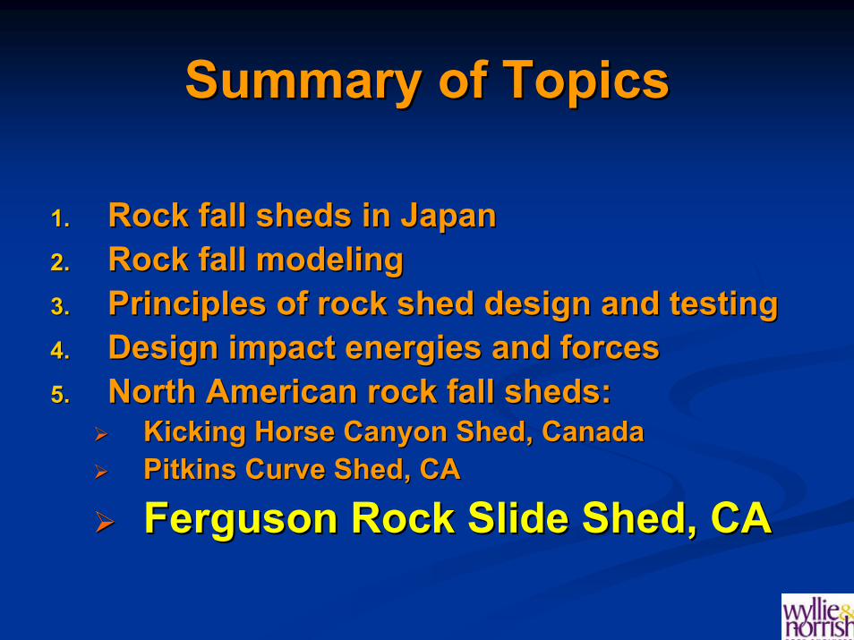
Summary of TopicsSummary of Topics
1.1. Rock fall sheds in JapanRock fall sheds in Japan2.2. Rock fall analysisRock fall analysis3.3. Principles of rock shed design and testingPrinciples of rock shed design and testing4.4. Design impact energies and forcesDesign impact energies and forces5.5. North American rock fall sheds:North American rock fall sheds:
Kicking Horse Canyon Shed, CanadaKicking Horse Canyon Shed, CanadaPitkins Curve Shed, CAPitkins Curve Shed, CAFerguson Rock Slide Shed, CAFerguson Rock Slide Shed, CA

ROCK FALL MITIGATION STUDYNIIGATA AND KANAZAWA
JAPAN
OCTOBER 20 TO 25, 2003

Niigata
To Tokyo
Kanazawa
Sea of Japan

Rock Sheds
Fence “Rock Keeper”
Concrete Barrier
Rock Shed
MSE Barrier
Sand Cushion
Styrofoam
5 10 20 50 100 200 300 500 1000
Rel
ativ
e C
onst
ruct
ion
Cos
t
5
10
5
0
100
2
00
500
Impact Energy Capacity (tf.m)
Styrofoam cushionSand
cushionSuper shed

SHEDSSHEDSRock Shed

Pre-cast concrete shed

“Super Rock Shed” – high ductility shed, capacity 800 tf m
Test loading:Mass = 44,000 lbHeight = 120 ft.

Summary of TopicsSummary of Topics
1.1. Rock fall sheds in JapanRock fall sheds in Japan2.2. Rock Rock fallfall analysisanalysis3.3. Principles of rock shed design and testingPrinciples of rock shed design and testing4.4. Design impact energies and forcesDesign impact energies and forces5.5. North American rock fall sheds:North American rock fall sheds:
Kicking Horse Canyon Shed, CanadaKicking Horse Canyon Shed, CanadaPitkins Curve Shed, CAPitkins Curve Shed, CAFerguson Rock Slide Shed, CAFerguson Rock Slide Shed, CA

Rock fall modeling programsRock fall modeling programs
Objective of modeling is to determine:Objective of modeling is to determine:Velocity of rock falls, which is used to determine impact Velocity of rock falls, which is used to determine impact energy on protection structureenergy on protection structureTrajectory of rock falls to determine dimensions of Trajectory of rock falls to determine dimensions of protection structure protection structure
Common modeling programs:Common modeling programs:CRSP CRSP –– Colorado Rockfall Simulation ProgramColorado Rockfall Simulation ProgramRockFall RockFall –– RocScienceRocScience
ModelledModelled trajectories are often too hightrajectories are often too high..

Typical computer simulation of rock falls

α
x
y
Impact point
Impact point
Velocity, V
Calculation of rock fall trajectoryCalculation of rock fall trajectory
⎟⎟⎠
⎞⎜⎜⎝
⎛⋅+⎟
⎠⎞
⎜⎝⎛
⋅⋅−= α
αtanx
cosVxg.y
2
50
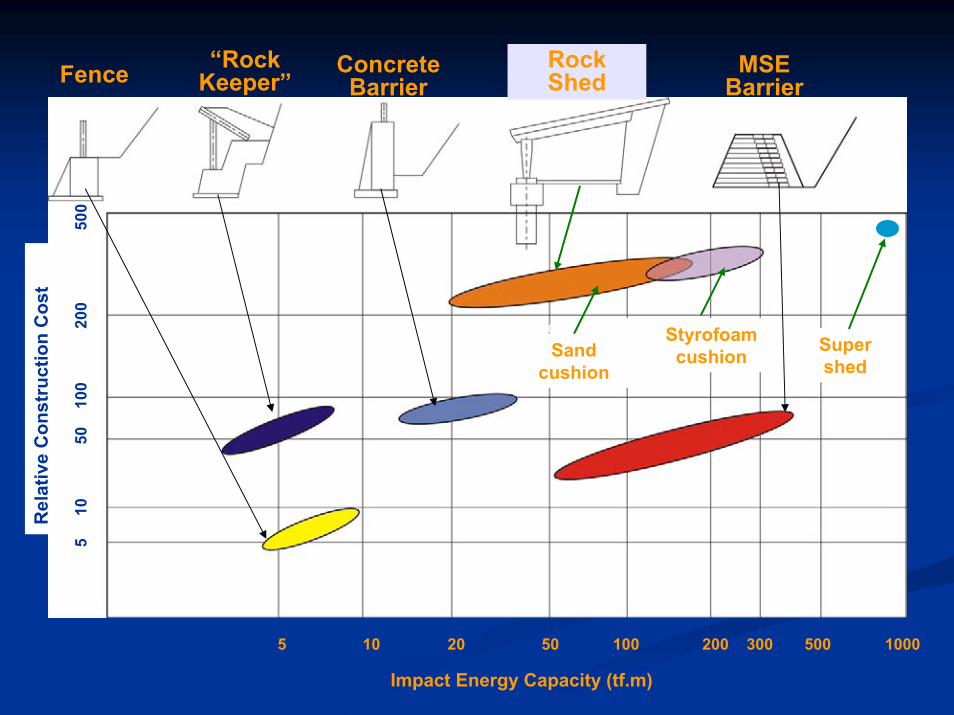
Rolling rock hazard -boulder travelled ~1 km from source
Impact marks on slope and bounce heights on trees used to calculate trajectory and velocity

Skagway, AK

Source of rock falls –blocks break up as they
impact the slope

Impact points on dockImpact points on dock

Trajectory calculationsTrajectory calculationsRock fall trajectories at base of slope

32 ft. high rock fall net

Measured Rock Fall Trajectories Measured Rock Fall Trajectories (Japan)(Japan)
No. of tests: 212Rock sizes: 300, 500, 700 mmShape: spherical, tabular

Energy Loss during Rock FallsEnergy Loss during Rock Falls
⎟⎟⎠
⎞⎜⎜⎝
⎛−⋅⋅=
ftanHgV
ψμ12
ψf
μ – friction coefficient at impact points
HgV ⋅⋅= 20
Free fall velocity:
Fall velocity, V

Rock fall velocitiesRock fall velocities
0
50
100
150
200
250
0 10 20 30 40 50 60 7
V e lo c it y (m/s)
Free fall velocity
Bare rock faces:Slope = 45°μ = 0.40 (impact)
Talus slopes:Slope = 31°μ = 0.35 (rolling)
Rock fall velocity, V (m/s)
Fall
heig
ht, H
(m)
Energy loss due to impacts
on slope
Skagway
Swiss test
Big Sur
Term
inal
vel
ocity
?
⎟⎟⎠
⎞⎜⎜⎝
⎛−⋅⋅=
ftanHgV
ψμ12

Summary of TopicsSummary of Topics
1.1. Rock fall sheds in JapanRock fall sheds in Japan2.2. Rock fall analysisRock fall analysis3.3. Principles of rock shed design Principles of rock shed design
and testingand testing4.4. Design impact energies and forcesDesign impact energies and forces5.5. North American rock fall sheds:North American rock fall sheds:
Kicking Horse Canyon Shed, CanadaKicking Horse Canyon Shed, CanadaPitkins Curve Shed, CAPitkins Curve Shed, CAFerguson Rock Slide Shed, CAFerguson Rock Slide Shed, CA

Weight impact force –mass x deceleration
Rock mass
Transmitted force distribution
Cushion material
Rock shed roof
Transfer of impact energy into shed structureTransfer of impact energy into shed structure
Weight impact force –mass x deceleration
Transmission impact force –integration of transmitted
pressure on distributed area
Cushion material

Instrumented shed to measure weight impact and transmission impact forces

W = 10kN
Span length
12m10m8m
0 5 10 15 200
2
00
400
60
0
Fall Height (m)M
axim
um re
actio
n fo
rce
(kN
)
Test Setup (plan view)
Load cell(Unit: mm)
2H-390X300X10X16 (Base beam)
Beam A
Beam B
250
Sand Tank
3175
Span length
Displacement meter
Earth pressure gauge
650
170
150 2H-390X300X10X16 (Main beam)
250
Test Setup (plan view)
Load cell(Unit: mm)
2H-390X300X10X16 (Base beam)
Beam A
Beam B
250
Sand Tank
3175
Span length
Displacement meter
Earth pressure gauge
650
170
150 2H-390X300X10X16 (Main beam)
250
Variation of weight and transmission impact forces with
time, full-scale tests
Span length (m)

Deformation
Styrofoam
Sand
Rubber tires
Forc
eRelationship between
force and deformation for three cushioning materials
Deformation

Pre-cast concrete shed
Hinge in column
Rigid connection between column and roof beam
Longitudinal connection between roof beams
Pinned connection

Hinge at base of column

Column
Roof beam
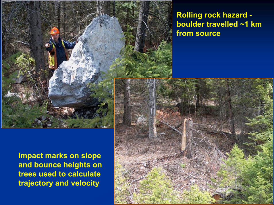
Post tensioned
cables
Rigid connection
between roof beams and
columns
Post tensioned cables joining
roof slabs

Summary of TopicsSummary of Topics
1.1. Rock fall sheds in JapanRock fall sheds in Japan2.2. Rock fall modelingRock fall modeling3.3. Principles of rock shed design and testingPrinciples of rock shed design and testing4.4. Design impact energies and Design impact energies and
forcesforces5.5. North American rock fall sheds:North American rock fall sheds:
Kicking Horse Canyon Shed, CanadaKicking Horse Canyon Shed, CanadaPitkins Curve Shed, CAPitkins Curve Shed, CAFerguson Rock Slide Shed, CAFerguson Rock Slide Shed, CA

Design Impact Load, Design Impact Load, PP
15352321082 −= βλ /// H)mg(.P
Japanese Rock Fall Protection Measures Handbook (2000)Japanese Rock Fall Protection Measures Handbook (2000)
m = rock fall mass (tonnes)λ = Lame constant, 1000 kNm-2 for soft sand cushioning material H = fall height, mβ = factor defining the relationship between the thickness of cushioning layer (T, m) and the diameter of the impacting rock (D, m)
580.
DT −
⎟⎠⎞
⎜⎝⎛=β

Relationship Cushion Thickness (T), Rock Fall Dimension (D) and Factor β
ββ
T/D
Large value for T adds
weight with little increase
in energy absorption

Distribution of impact load through Distribution of impact load through cushion on to roof of shedcushion on to roof of shed
Sand cushion, thickness T
Effective area of transmitted force on
roof, A
4
2TA π=
Roof

Summary of TopicsSummary of Topics
1.1. Rock fall sheds in JapanRock fall sheds in Japan2.2. Rock fall analysisRock fall analysis3.3. Principles of rock shed design and testingPrinciples of rock shed design and testing4.4. Design impact energies and forcesDesign impact energies and forces5.5. North American rock fall sheds:North American rock fall sheds:
Kicking Horse Canyon Shed, Kicking Horse Canyon Shed, CanadaCanadaPitkins Curve Shed, CAPitkins Curve Shed, CAFerguson Rock Slide Shed, CAFerguson Rock Slide Shed, CA

Kicking Horse Canyon

Rock falls are concentrated in gulliesRock falls are concentrated in gullies
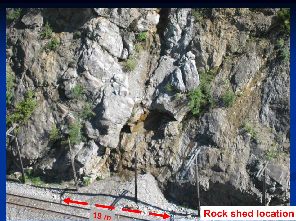
Rock shed location19 m

Clearance envelope
“Crash” wall with socket connection to column
Column (pre-cast)
with flexible hinge
Granular fill Rock anchor
with tie-back through wall
Sand cushion 900 mm thick
Rigid connection – post-tensioned cables
Footing supported with rock socketed
pilesRock fill
supporting track
Roof beams (pre-cast) with ducts for longitudinal
connection cables
Retaining wall (cast in place)
Footing dowelled to
rock foundation
Pinned connection with rubber pad
Clearance envelope

Top of “crash” wall with sockets for lower ends of
columns.
Valley-side
columns, 1500 O.C.
Concrete blocks to
retain sand
cushion
Elevation view
Roof beams

Summary of TopicsSummary of Topics
1.1. Rock fall sheds in JapanRock fall sheds in Japan2.2. Rock fall analysisRock fall analysis3.3. Principles of rock shed design and testingPrinciples of rock shed design and testing4.4. Design impact energies and forcesDesign impact energies and forces5.5. North American rock fall sheds:North American rock fall sheds:
Kicking Horse Canyon Shed, CanadaKicking Horse Canyon Shed, Canada
Pitkins Curve Shed, CAPitkins Curve Shed, CAFerguson Rock Slide Shed, CAFerguson Rock Slide Shed, CA

Pitkins Curve, Highway 1, CAPitkins Curve, Highway 1, CA

Pitkins Curve Shed• 45 m high rock face• Design rock fall ~2.5 m

Artists rendering of completed project
Roof protection –Styrofoam with sand covering

Widely spaced columns to maximize view of ocean
Summary of TopicsSummary of Topics
1.1. Rock fall sheds in JapanRock fall sheds in Japan2.2. Rock fall modelingRock fall modeling3.3. Principles of rock shed design and testingPrinciples of rock shed design and testing4.4. Design impact energies and forcesDesign impact energies and forces5.5. North American rock fall sheds:North American rock fall sheds:
Kicking Horse Canyon Shed, CanadaKicking Horse Canyon Shed, CanadaPitkins Curve Shed, CAPitkins Curve Shed, CA
Ferguson Rock Slide Shed, CAFerguson Rock Slide Shed, CA
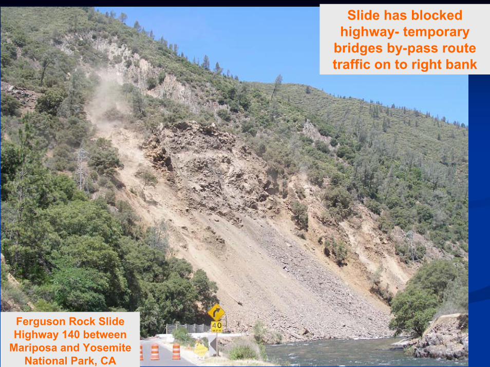
Slide has blocked highway- temporary
bridges by-pass route traffic on to right bank
Ferguson Rock Slide Highway 140 between
Mariposa and Yosemite National Park, CA
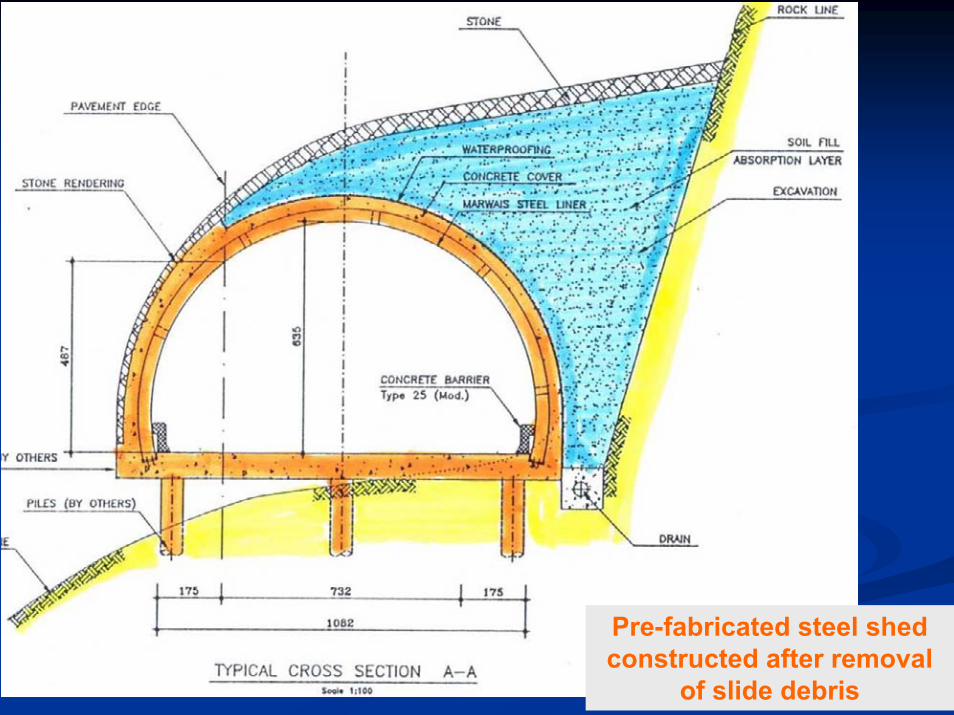
Pre-fabricated steel shed constructed after removal
of slide debris

Steel shed design based on technology to protect
aircraft from missile attack

Steel shed under
construction

ConclusionsConclusions1. Rock fall modeling can produces excessively high
trajectories based on observations of actual rock falls2. Information needed on impact friction coefficients
related to slope surface conditions3. Extensive testing of rock fall sheds in Japan provides
reliable information on design impact forces4. Rock sheds constructed with flexible components that
absorb impact energy5. Properties and thickness of cushioning material (sand
and/or Styrofoam) influences magnitude of transmitted impact force
Thank you

Impact positions of rock falls on Impact positions of rock falls on roof of shedroof of shed
ψP′ P

Envelope of Rock Fall Envelope of Rock Fall TrajectoriesTrajectories
Source
Trajectory envelope
Trajectory height, h
Angular velocity
Translational velocity
ψf

Steel shed

Ferguson Rock Slide Highway 140 between
Mariposa and Yosemite National Park, CA

Deflection sheds

Measured Rock Fall TrajectoriesMeasured Rock Fall Trajectories
Fall
heig
ht, H
(m)
Trajectory height, h (m)
90% envelope
Related Documents