1 Rock Anchoring & Foundation System Introduction: The Rock Anchoring & Foundation System is a Patented efficient and economical solution for the installation of Anchors and Foundations in Rock and/or any Solid Media. The System is Ecologically sound as it requires no excavation or removal of spoils and has no vibration, hammering or explosive requirements in its installation. No bonding agent required in the installation process as the System Components, upon their placement, directly transfers the applied design forces directly into the surrounding media. The System can be designed and installed to handle any intensity and type of loading placed upon it and is only limited by the strength of the surrounding media itself. It is easily installed with a minimum amount of time, labor and equipment. Once installed, the System can be easily tested to its design/ultimate load bearing capacity and is ready for immediate use with known installed structural integrity. No drying and/or curing time required. Anchor Design, Installation & Testing Procedures: • As with other rock anchors, the design of the System normally requires core sampling that identifies the consistency, type and strength of the load bearing media. The position/depth of the System is determined. The required design loading will determine the bar size required. Standard sizes available range from diameters of 1 to 2 1/2 inches with minimum ultimate strengths of 127.5 to 778 kips. The hole size required for the installation will normally be 1 inch greater than the bar diameter. Core sampling ideally would be taken at precise location the System is designed for. Upon withdrawing and inspecting the core samples, the Anchoring System can be installed immediately in the precise position as determined by the inspection of the samples. The System, consisting of the anchor head attached to the bar, which is encased by the spreading column, is lowered into the hole. The spreading/spinner apparatus is attached and centered in contact with the surface. The System is rotated, using the core sampling power unit, opening the anchor head into the load bearing media, in a predetermined controlled manner. This places the anchor head conically into the rock, which effectively utilizes the maximum strength of the load bearing rock via the Anchoring System. The casing, if used and required for coring by soils overburden, and/or the spreading column is

Welcome message from author
This document is posted to help you gain knowledge. Please leave a comment to let me know what you think about it! Share it to your friends and learn new things together.
Transcript
1
Rock Anchoring & Foundation SystemIntroduction:The Rock Anchoring & Foundation System is a Patented efficient and economical solution forthe installation of Anchors and Foundations in Rock and/or any Solid Media. The System is
Ecologically sound as it requires no excavation or removal of spoils and has no vibration,hammering or explosive requirements in its installation. No bonding agent required in the
installation process as the System Components, upon their placement, directly transfers the
applied design forces directly into the surrounding media. The System can be designed andinstalled to handle any intensity and type of loading placed upon it and is only limited by the
strength of the surrounding media itself. It is easily installed with a minimum amount of time,labor and equipment. Once installed, the System can be easily tested to its design/ultimate load
bearing capacity and is ready for immediate use with known installed structural integrity.
No drying and/or curing time required.
Anchor Design, Installation & Testing Procedures:• As with other rock anchors, the design of the System normally requires core sampling
that identifies the consistency, type and strength of the load bearing media. The
position/depth of the System is determined. The required design loading will determinethe bar size required. Standard sizes available range from diameters of 1 to 2 1/2 inches
with minimum ultimate strengths of 127.5 to 778 kips. The hole size required for theinstallation will normally be 1 inch greater than the bar diameter. Core sampling ideally
would be taken at precise location the System is designed for. Upon withdrawing and
inspecting the core samples, the Anchoring System can be installed immediately in theprecise position as determined by the inspection of the samples. The System, consisting
of the anchor head attached to the bar, which is encased by the spreading column, islowered into the hole. The spreading/spinner apparatus is attached and centered in
contact with the surface. The System is rotated, using the core sampling power unit,
opening the anchor head into the load bearing media, in a predetermined controlledmanner. This places the anchor head conically into the rock, which effectively utilizes
the maximum strength of the load bearing rock via the Anchoring System. The casing, ifused and required for coring by soils overburden, and/or the spreading column is
2Anchor Design, Installation & Testing Procedures (cont’d.):
removed, allowing the System to be immediately tested and placed into the use it was
designed for.• Where the Rock Anchoring System is used in applications with rock at the surface,
without coring requirements, its installation is greatly simplified. The drilled hole size isdetermined by the design loading. The hole is drilled to the desired System depth. The
System, consisting of the anchor head attached to the bar, which is encased by the
spreading column, is lowered into the hole. The spreading/spinner apparatus is attachedand centered in contact with the surface. The System is rotated using the hole drilling
power unit, opening the anchor head into the load bearing media, in a predetermined
controlled manner. This places the anchor head conically into the rock, which effectivelyutilizes the maximum strength of the load bearing rock via the Anchoring System. The
spreading column is removed allowing the System to be immediately tested and placedinto its designed use. If required, the System may be post-tensioned in order to meet
current seismic loading safety measures. Corrosion protection for the bars can be
accomplished via any desired methods currently used. The force transmitting Anchorhead can be made of stainless steel, which can handle any compressive force that is place
on it. The bar is the only component of the System that experiences the tensile forcesplaced upon the System, which can also be made of stainless steel.
Foundation Design, Installation & Testing Procedures:The Foundation System is installed using the Anchoring System, The Anchoring Systemprovides a predetermined axial installing load in the precise direction required by the installation
and loading of the Foundation System. Foundation uplift/pull out forces, when present in theSystem, are handled by directly attaching the Foundation to the Anchor in their final installed
and tested position. The Foundation System can be designed, installed and tested to handle
virtually and type and intensity of loading, such as overturning and torsional moments, angularand ground line shear and bearing. Upon reaching its final installed position, the final applied
and held installing load is a direct indication of its ultimate strength, allowing the immediate use
of the System. In rock the System can be pulled into a rock socket. When installed in soils theinstalling force is applied and installing movement is controlled in a predetermined manner.
This increases the load handling capacities of the soils, via their compaction/consolidation, and
3Foundation Design, Installation & Testing Procedures (cont’d.): Virtually eliminates settlement, as the entire Foundation System, including the load bearing
soils, has been pre-stressed/tested to its design loading. Post-tensioned during the installationprocess. In the final installed position of the System any desired portion of the installing load
may be locked in to meet current seismic loading safety measures. Corrosion protection for theAnchor bars and the Foundation System can be accomplished via any desired methods currently
used. The force transmitting Anchor head can be made of stainless steel, which can handle any
compressive force that is place on it. The bar is the only component of the System thatexperiences the tensile forces placed upon the System.
Present Art of Designing and Installing Rock Anchorages:• High capacity rock anchors are generally post-tensioned. There are two distinct types of
pre-stressed anchors in widespread use distinguished by tendon type: bar anchors and
strand anchors. Both require drilling, cleaning and water testing of the borehole prior toestablishing a cured grout bond of the tendon component to the rock bore hole surface.
The bond zone, depth and diameter of drill hole surface required for bonding strength,
will vary due to the types of rock encountered. The grout must be cured between thetendon component and the borehole wall prior to post-tensioning.
• Resin grout bonded rock anchors are currently considered as the most economicaltemporary rock anchor. Its installation requires a tight, non-permeable, clean and dry
borehole. The bond length is limited, as its entire length must be pushed into the epoxy
and spun prior to reaching the gel time of the epoxy, requiring fast installations. It cannotbe used in all types of rock.
• Mechanical rock anchors are installed via an anchor shell and a cone used to develop afriction lock between the rock and head assembly. Their use is limited to concrete and
soft rock and have minimal load-handling capabilities.
Present Art of Designing and Installing Combined Post-Tensioned Rock
Anchorage and Foundation Systems:There is no known practice system for installing foundations in rock, soils or any combinations
thereof using rock anchors where the entire system, including the surrounding load-bearing
4Present Art of Designing and Installing Combined Post-Tensioned Rock
Anchorage and Foundation Systems (cont’d):media, can be tested and post-tensioned and/or load tested to a designed loading. Post-tensioning
foundations would require a sound & reliable anchoring system for all rock and soils types withcomplete geotechnical site/media investigation prior to the system design. A combination of
rock engineering and soils engineering experience would be required. In most cases foundations
are designed with large safety factors, installed and placed into use without being post-tensionedand/or load tested.
Advantages of using The Rock Anchoring and Foundation System as compared to
The Present Art of designing and installing rock anchors and foundations:The proprietary apparatus and method for installing an anchor head conically into a rock socket
is the enabling factor in the creation of the advantages and need for this technology as compared
to existing practices. The Anchor Head directly transmits the applied load outwardly into thesurrounding rock. This allows the full strength of the load bearing rock to be used. The
following is a list of use advantages which is not all inclusive:• Bonding grout or resins are not used.
o No curing or gel time is required.
o Drilling depth in rock is greatly reduced as required bonding length is totallyeliminated.
o In a post-tensioned installation the entire rod, starting at the anchor head, can be
considered as the tendon with the anchor head being the anchor.o The pre-installation requirements of a tight, non-permeable, clean and dry borehole
are totally eliminated.o All installed Systems can be immediately placed into use upon completing the
appropriate pre-designed installation process.
• The structural strength of the installed system is known upon installation, including post-tensioned systems.
• The design process and its associated time requirements are greatly simplified along with thereduction of its associated liabilities:
o Provides a single system and method that can be used in the design & installation of
standard or post-tensioned foundation and/or rock anchoring systems.
5Advantages of using The Rock Anchoring and Foundation System as compared to
The Present Art of designing and installing rock anchors and foundations (cont’d.):o When the strength of the rock and, if present, the overlaying soils is known it is
relatively simple to select the anchorage and design the foundation.o There are no novel design procedures or formulae, required in the design process, that
are not being used in the present art.
o Rock coring can be accomplished at the precise location of the installed system andthe system can be immediately installed using the coring system. This would allow
geotechnical testing firms to have an added revenue producing function.• Provides a large overall reduction in project costs in the following areas;
o Design time and costs.
o Elimination of required material and their associated installation and curing time.o Rock drilling depths and borehole size are reduced significantly.
o Equipment costs are reduced.• Allows an advance in seismic engineering by providing an easily designed and installed post-
tensioned system for foundations and/or anchoring systems with known structural integrity
upon their installation.• Allows an improvement in permafrost engineering by providing an easily designed and
installed post-tensioned system for foundations and/or anchoring systems with knownstructural integrity upon their installation.
• Allows development of a complete sound, safe and reliable system for mobile home
foundations and anchors.
Barriers to Market Entry and their Possible Solutions:• Acceptance of the technology – The only change is the rock anchor head which clearly
apparent in its use and benefits.
• Lack of testing use/results – The only part of the System that is different is the anchor head
and its installation. Testing can be easily & economically accomplished in surface rockalong with being certified by a reputable geotechnical testing lab locally.
• Contractor acceptance, when different to materials and procedures they are currently using –
Due to its time and cost benefits along with its known structural integrity, upon installation,
6Barriers to Market Entry and their Possible Solutions (cont’d.): designers and users will quickly change their requirements/specifications. Contractors will
be able to perform the installations using the same equipment they have. The only added equipment needed would be the spinner/expanding apparatus, which could be purchased at
a minimal cost.
• Lack of funding for development, testing and marketing – The simplicity and soundness of
this proposal will attract investors, Another consideration would be to develop a strategic
alliance with a rod and/or an anchor head manufacturer. The development of a hand toolsystem powered by a standard drill/driver for smaller anchors would open possible strategic
alliances for marketing by major retailers and/or tool distributors for the home owner and
small contractor markets, would also be a potential source of funding.
Use Areas/Industries:Anywhere foundations and/or rock anchors are used is a potential use area. A marketing planmust be developed to target customers and/or alliances that would create sales in a manner that
will satisfy our ongoing financial needs, which includes funding for the plan.
The Rock Anchoring & Foundation System Post-Tensioned Systems
Free
Str
ess
Leng
th
Free
Str
ess
Leng
th
Free
Str
ess
Leng
th
Rock
Soils
Compacted Consolidated Soils
Rock
Rock
Compacted Consolidated Soils
Soils
Soils
Fins
Ribs
Perimeter of Load BearingZones of Influence
Perimeter of Load BearingZones of Influence
Perimeter of Load BearingZones of Influence
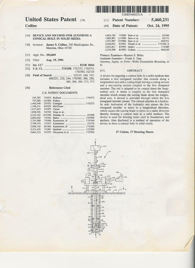
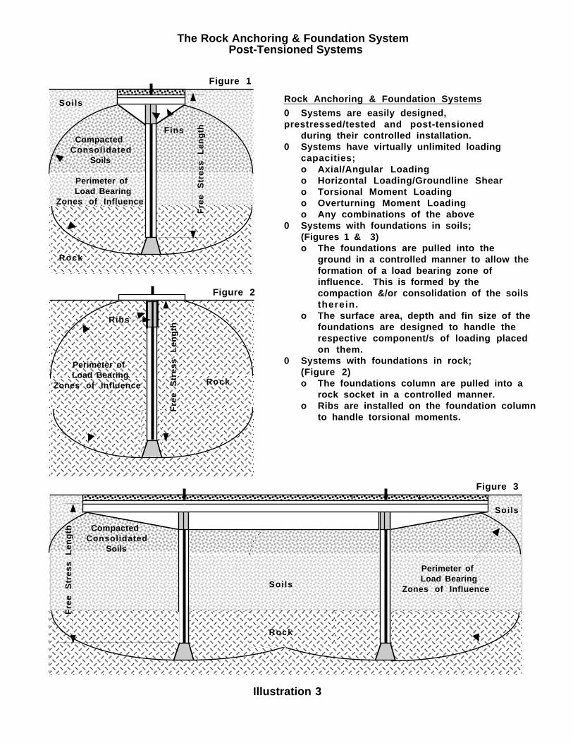
Rock Anchoring & Foundation Systems0 Systems are easily designed, prestressed/tested and post-tensioned during their controlled installation. 0 Systems have virtually unlimited loading
capacities;o Axial/Angular Loadingo Horizontal Loading/Groundline Shear o Torsional Moment Loadingo Overturning Moment Loadingo Any combinations of the above
0 Systems with foundations in soils; (Figures 1 & 3)o The foundations are pulled into the
ground in a controlled manner to allow the formation of a load bearing zone of influence. This is formed by the compaction &/or consolidation of the soils therein.
o The surface area, depth and fin size of the foundations are designed to handle the respective component/s of loading placed on them.
0 Systems with foundations in rock;(Figure 2)o The foundations column are pulled into a
rock socket in a controlled manner.o Ribs are installed on the foundation column
to handle torsional moments.
Figure 1
Figure 2
Figure 3
Illustration 3
The Rock Anchoring & Foundation System Post-Tensioned Systems
Illustration 4
Free Stress Length (typical)
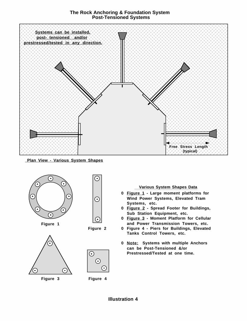
Systems can be installed, post- tensioned and/orprestressed/tested in any direction.
Plan View - Various System Shapes
Figure 1Figure 2
Figure 4Figure 3
Various System Shapes Data0 Figure 1 - Large moment platforms for
Wind Power Systems, Elevated Tram Systems, etc.
0 Figure 2 - Spread Footer for Buildings, Sub Station Equipment, etc.
0 Figure 3 - Moment Platform for Cellularand Power Transmission Towers, etc.
0 Figure 4 - Piers for Buildings, Elevated Tanks Control Towers, etc.
0 Note: Systems with multiple Anchors can be Post-Tensioned &/or Prestressed/Tested at one time.
The Rock Anchor & Foundation System Hand Tool ApplicationRock Auger Anchor Foundation System Patent # 5,460,231
Illustration 5
Shel
l C
asin
g In
sert
Spin
ner
Expa
nder
Ass
embl
yA
ncho
r H
ead
Ass
embl
y
Figure 1
Figure 2
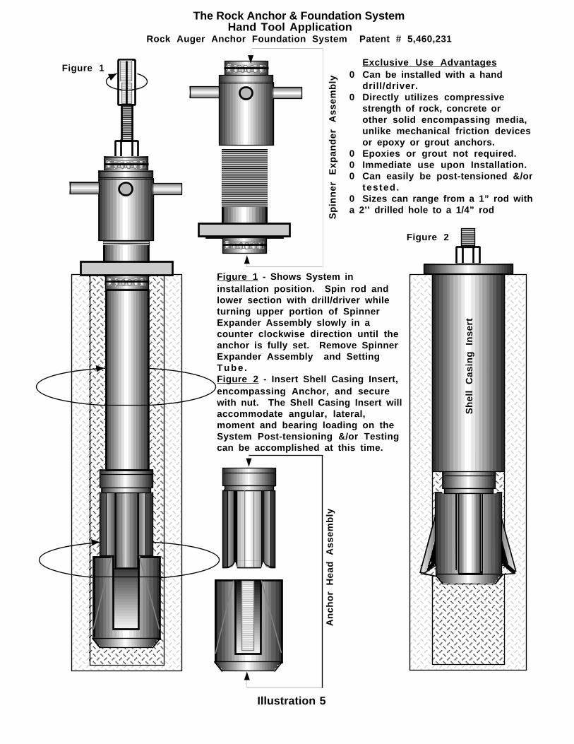
Exclusive Use Advantages0 Can be installed with a hand
drill/driver.0 Directly utilizes compressive
strength of rock, concrete or other solid encompassing media, unlike mechanical friction devices or epoxy or grout anchors.
0 Epoxies or grout not required.0 Immediate use upon Installation.0 Can easily be post-tensioned &/or
tested.0 Sizes can range from a 1” rod with a 2’’ drilled hole to a 1/4” rod
Figure 1 - Shows System in installation position. Spin rod and lower section with drill/driver while turning upper portion of Spinner Expander Assembly slowly in a counter clockwise direction until the anchor is fully set. Remove Spinner Expander Assembly and Setting Tube .Figure 2 - Insert Shell Casing Insert, encompassing Anchor, and secure with nut. The Shell Casing Insert will accommodate angular, lateral, moment and bearing loading on the System Post-tensioning &/or Testing can be accomplished at this time.
Front View
The Rock Anchoring & Foundation System Rock Auger Anchor Foundation System Patent # 5,460,231
Front View
Roc
k C
ombi
ned
Mom
ent/B
eari
ng F
ound
atio
n
RockAnchor
Leading edge of Anchor Cutting Surfaces are coated with Carbide Chips or industrial diamonds
Fvp
Fha
RFva
Fvp
Fva
Fha
R
Foundation Bearing Plate
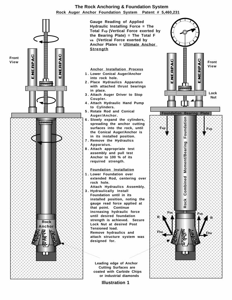
Gauge Reading of AppliedHydraulic Installing Force = The Total Fvp (Vertical Force exerted by the Bearing Plate) = The Total Fva (Vertical Force exerted by Anchor Plates = Ultimate Anchor Strength
Anchor Installation Process1 . Lower Conical Auger/Anchor
into rock hole.2 . Place Hydraulics Apparatus
with attached thrust bearingsin place.
3 . Attach Auger Driver to StopCoupler.
4 . Attach Hydraulic Hand Pumpto Cylinders.
5 . Rotate Rod and ConicalAuger/Anchor.
6 . Slowly expand the cylinders,spreading the anchor cuttingsurfaces into the rock, untilthe Conical Auger/Anchor is in its installed position.
7 . Remove the HydraulicsApparatus.
8 . Attach appropriate test assembly and pull test
Anchor to 100 % of itsrequired strength.
Foundation Installation1 . Lower Foundation over
extended Rod, centering overrock hole.Attach Hydraulics Assembly.
3 . Hydraulically InstallFoundation until in itsinstalled position, noting thegauge read force applied atthat point. Continueincreasing hydraulic forceuntil desired foundationstrength is achieved. Secure Lock Nut at desired PostTensioned load. Remove hydraulics andattach structure system wasdesigned for.
Lock Nut
Illustration 1
Free
Str
ess
Leng
th
Free
Str
ess
Leng
th
Free
Str
ess
Leng
th
Req
uire
d B
ond
Leng
th
Req
uire
d R
ock
Dep
thR
equi
red
R
ock
De
pth
Req
uire
d R
ock
Dep
th
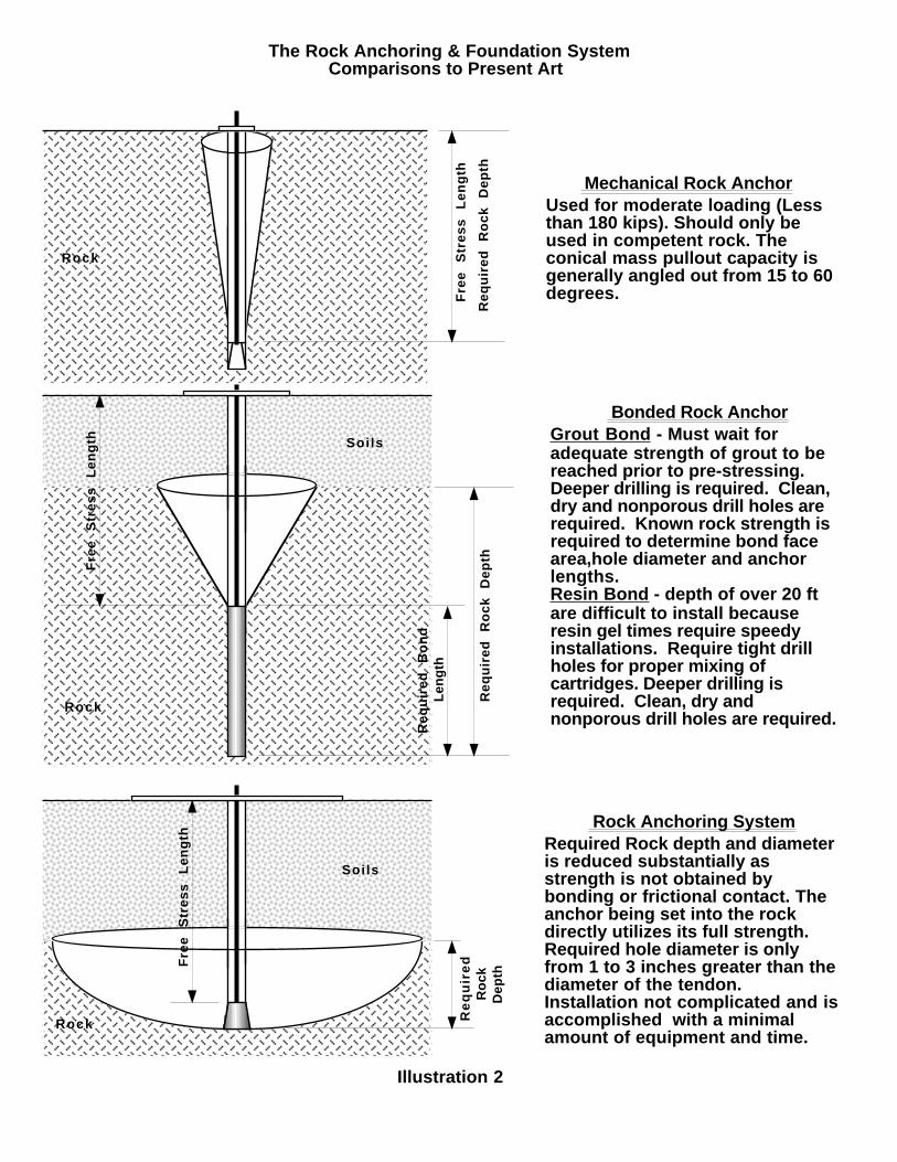
Mechanical Rock AnchorUsed for moderate loading (Less than 180 kips). Should only be used in competent rock. The conical mass pullout capacity is generally angled out from 15 to 60 degrees.
Bonded Rock AnchorGrout Bond - Must wait for adequate strength of grout to be reached prior to pre-stressing. Deeper drilling is required. Clean, dry and nonporous drill holes are required. Known rock strength is required to determine bond face area,hole diameter and anchor lengths.Resin Bond - depth of over 20 ft are difficult to install because resin gel times require speedy installations. Require tight drill holes for proper mixing of cartridges. Deeper drilling is required. Clean, dry and nonporous drill holes are required.
Rock Anchoring SystemRequired Rock depth and diameter is reduced substantially as strength is not obtained by bonding or frictional contact. The anchor being set into the rock directly utilizes its full strength. Required hole diameter is only from 1 to 3 inches greater than the diameter of the tendon. Installation not complicated and is accomplished with a minimal amount of equipment and time.
The Rock Anchoring & Foundation System Comparisons to Present Art
Illustration 2
Rock
Rock
Rock
Soils
Soils
Related Documents