132 IEEE TRANSACTIONS ON ROBOTICS AND AUTOMATION, VOL 12, NO. 5, OCTOBER 1996 ust Visual Servoing in 3-D Reaching Tasks Enrico Grosso, Giorgio Metta, Andrea Oddera, and Giulio Sandini Abstract-This paper describes a novel approach to the prob- lem of reaching an object in space under visual guidance. The approach is characterized by a great robustness to calibration errors, such that virtually no calibration is required. Servoing is based on binocular vision: a continuous measure of the end- effector motion field, derived from real-time computation of the binocular optical flow over the stereo images, is compared with the actual position of the target and the relative error in the end-effector trajectory is continuously corrected. The paper outlines the general framework of the approach, shows how visual measures are obtained and discusses the synthesis of the controller along with its stability analysis. Real-time experiments are presented to show the applicability of the approach in real 3-D applications. Index Terms-Visual servoing, 3-D reaching, robot manipula- tion, stereo vision. I. INTRODUCTION BASIC skill for a manipulating actor is the ability to reach an object in space. Apart from trivial cases, in which the position of the object to be reached is a-priori known in the arm coordinate system, the acquisition of some kind of sensory information is indispensable to guide the end-effector toward the target. This requirement becomes crucial whenever the system has to cope with moving objects, obstacles and/or unexpected events and in all cases where the kinematics andor the dynamics of the reaching device is altered (for example when the task requires the use of a hand-held tool). Because of its unique role during the “pre-contact” phases of manipulation, vision has been, and still is, considered crucial to acquire geometric and dynamic information about the environment and to guide motor and, particularly, reaching actions. Within this framework two main paradigms have been proposed: the so-called 3-0 metric paradigm and the visual sewoing approach. In the 3-D metric paradigm [l], [2] the control error function is built in the 3-D Cartesian space and, consequently, visual information has to be mapped from image space to the 3-D space on the basis of a precise camera model obtained through a calibration procedure. In the visual servoing approach [3], which is very much related to the active vision paradigm [4], [5], [6], the error function is computed Manuscript received March 2, 1995; revised January 11, 1996. This work was supported by the European Community under ESPRIT-BRA Project SECOND and by a Grant from Hewlett-Packard Italy. This paper was recommended for publication by Associate Editor S. Hutchinson and Editor S. E. Salcudean upon evaluation of reviewers’ comments. E. Grosso, G. Metta, and G. Sandini are with the Department of Commu- nication, Computer and Systems Science (DIST), Integrated Laboratory for Advanced Robotics (LIRA-Lab.), University of Genoa, 16145 Genoa, Italy A. Oddera is with AITEK S.r.l., 16145 Genoa, Italy. Publisher Item Identifier S 1042-296X(96)07237-0. in the image space [7]-[lo] and the calibration requirements are somehow less demanding allowing the synthesis of more robust control laws. The tradeoff between these two approaches is probably measured in terms of reaching strategy: if the reaching action has to be programmed as a single, ballistic motion of the arm, a very accurate calibration is required. On the other hand, if the reaching action can be controlled during its execution (allowing for “on-the-fly’’ correction of errors), the visual servoing approach may be more convenient because of its intrinsic flexibility to environmental as well as internal changes [Ill. In the case of visual servoing, task completion in the image space must correspond to the correct task execution in the Cartesian control space and, therefore, designing a task requires the selection of a set of visual features and state variables which allow a complete and univocal description of the action to be performed. Depending on the specific task, on the camera-arm configuration, and on the available computational power, different visual measures have been proposed [ 121, [13]. They are mainly based on static features detected and tracked throughout the temporal image sequence. Among the techniques proposed to synthesize the control law, significant examples are the optimal control approach [9] or the task functions approach proposed by Espiau and his colleagues Extending ideas presented in some previous work [15], [ 161, this paper presents an original contribution to the vi- sual servoing paradigm based on object-centered static and dynamic visual features. The combined use of disparity and image velocity information virtually eliminates the need of calibrating the apparatus to the extent that the transformation between the camera and the arm coordinate systems need to be know only qualitatively, resulting in a very robust control law. In this respect, therefore, the approach presented here is more similar to the one proposed in [17] based on a rough calibration than to the one based on on-line calibration [18] because the only requirement in term of calibration is that both the intrinsic and extrinsic camera parameters, as well as the actual relative position between the arm and the vision system remain within given limits. For example, as to the stereo set-up, both cameras should mount the same kind of lens, their optical axes should lie approximately on a plane, and the field-of-view should be wide enough for the object and the end effector to be simultaneously visible during the reaching task. As to the transformation between the camera and the arm coordinate system the only requirement is a very rough knowledge of the relative orientation. Based upon these ~141. 1042-296W96$05.00 0 1996 IEEE Authorized licensed use limited to: University of Sassari. Downloaded on March 03,2010 at 05:01:43 EST from IEEE Xplore. Restrictions apply.

Welcome message from author
This document is posted to help you gain knowledge. Please leave a comment to let me know what you think about it! Share it to your friends and learn new things together.
Transcript
132 IEEE TRANSACTIONS ON ROBOTICS AND AUTOMATION, VOL 12, NO. 5, OCTOBER 1996
ust Visual Servoing in 3-D Reaching Tasks Enrico Grosso, Giorgio Metta, Andrea Oddera, and Giulio Sandini
Abstract-This paper describes a novel approach to the prob- lem of reaching an object in space under visual guidance. The approach is characterized by a great robustness to calibration errors, such that virtually no calibration is required. Servoing is based on binocular vision: a continuous measure of the end- effector motion field, derived from real-time computation of the binocular optical flow over the stereo images, is compared with the actual position of the target and the relative error in the end-effector trajectory is continuously corrected. The paper outlines the general framework of the approach, shows how visual measures are obtained and discusses the synthesis of the controller along with its stability analysis. Real-time experiments are presented to show the applicability of the approach in real 3-D applications.
Index Terms-Visual servoing, 3-D reaching, robot manipula- tion, stereo vision.
I. INTRODUCTION
BASIC skill for a manipulating actor is the ability to reach an object in space. Apart from trivial cases, in
which the position of the object to be reached is a-priori known in the arm coordinate system, the acquisition of some kind of sensory information is indispensable to guide the end-effector toward the target. This requirement becomes crucial whenever the system has to cope with moving objects, obstacles and/or unexpected events and in all cases where the kinematics andor the dynamics of the reaching device is altered (for example when the task requires the use of a hand-held tool).
Because of its unique role during the “pre-contact” phases of manipulation, vision has been, and still is, considered crucial to acquire geometric and dynamic information about the environment and to guide motor and, particularly, reaching actions.
Within this framework two main paradigms have been proposed: the so-called 3-0 metric paradigm and the visual sewoing approach. In the 3-D metric paradigm [l], [2] the control error function is built in the 3-D Cartesian space and, consequently, visual information has to be mapped from image space to the 3-D space on the basis of a precise camera model obtained through a calibration procedure. In the visual servoing approach [3], which is very much related to the active vision paradigm [4], [ 5 ] , [6], the error function is computed
Manuscript received March 2, 1995; revised January 11, 1996. This work was supported by the European Community under ESPRIT-BRA Project SECOND and by a Grant from Hewlett-Packard Italy. This paper was recommended for publication by Associate Editor S. Hutchinson and Editor S. E. Salcudean upon evaluation of reviewers’ comments.
E. Grosso, G. Metta, and G. Sandini are with the Department of Commu- nication, Computer and Systems Science (DIST), Integrated Laboratory for Advanced Robotics (LIRA-Lab.), University of Genoa, 16145 Genoa, Italy
A. Oddera is with AITEK S.r.l., 16145 Genoa, Italy. Publisher Item Identifier S 1042-296X(96)07237-0.
in the image space [7]-[lo] and the calibration requirements are somehow less demanding allowing the synthesis of more robust control laws.
The tradeoff between these two approaches is probably measured in terms of reaching strategy: if the reaching action has to be programmed as a single, ballistic motion of the arm, a very accurate calibration is required. On the other hand, if the reaching action can be controlled during its execution (allowing for “on-the-fly’’ correction of errors), the visual servoing approach may be more convenient because of its intrinsic flexibility to environmental as well as internal changes [ I l l .
In the case of visual servoing, task completion in the image space must correspond to the correct task execution in the Cartesian control space and, therefore, designing a task requires the selection of a set of visual features and state variables which allow a complete and univocal description of the action to be performed. Depending on the specific task, on the camera-arm configuration, and on the available computational power, different visual measures have been proposed [ 121, [13]. They are mainly based on static features detected and tracked throughout the temporal image sequence. Among the techniques proposed to synthesize the control law, significant examples are the optimal control approach [9] or the task functions approach proposed by Espiau and his colleagues
Extending ideas presented in some previous work [15], [ 161, this paper presents an original contribution to the vi- sual servoing paradigm based on object-centered static and dynamic visual features. The combined use of disparity and image velocity information virtually eliminates the need of calibrating the apparatus to the extent that the transformation between the camera and the arm coordinate systems need to be know only qualitatively, resulting in a very robust control law. In this respect, therefore, the approach presented here is more similar to the one proposed in [17] based on a rough calibration than to the one based on on-line calibration [18] because the only requirement in term of calibration is that both the intrinsic and extrinsic camera parameters, as well as the actual relative position between the arm and the vision system remain within given limits. For example, as to the stereo set-up, both cameras should mount the same kind of lens, their optical axes should lie approximately on a plane, and the field-of-view should be wide enough for the object and the end effector to be simultaneously visible during the reaching task. As to the transformation between the camera and the arm coordinate system the only requirement is a very rough knowledge of the relative orientation. Based upon these
~141.
1042-296W96$05.00 0 1996 IEEE
Authorized licensed use limited to: University of Sassari. Downloaded on March 03,2010 at 05:01:43 EST from IEEE Xplore. Restrictions apply.
GROSS0 6’1 01: ROBUST VISUAL SERVOING IN 3-D REACHING TASKS 733
loose calibration requirements a control law is synthesized and its stability demonstrated using a Lyapunov-like approach [ 191.
In the next section the proposed approach is described and put into context of a head-eye-hand system. Section 111 will describe the theoretical framework of the approach, followed by Sections IV and V presenting the synthesis and stability analysis of the controller. Visual processing is described in Section VI, followed by the presentation of the experimental results (Section VII).
11. MOTIVATION OF THE APPROACH
The starting point of the research results presented in this paper was a simple observation regarding human performance during thc cxccution of manipulative actions: the proprio- ceptive sensors (the “biological encoders”) as well as the internal kinematic representation of the human body are far less accurate than the accuracy observed in the execution of even simple reaching tasks. For example if you draw a point on a sheet of paper and than, after closing the eyes and moving the arm, you try to “redraw” the same point, you will experience the low accuracy in assuming the same posture. Or if you try to recap a pen you may easily verify how performance degrades with the closing of the eyes. Yet, all the information should be known to the system.
Besides the interesting biological questions arising, which are outside the scope of this paper, our attempt has been devoted to try to identify possible solutions to reaching tasks which do not require an accurate metric estimation of the end effector position with respect to the cameras coordinate system. This requirement impacts not only on the estimation of the camera intrinsic parameters (which in the case of humans may be supposed to be known) but, more importantly, on the estimation of the spatial relationship between the head and the arm. Putting this observation in a more general perspective of an eye-head-hand robotic system, it is worth noting that when the complexity of the mechanical apparatus increases, any approach based on accurate calibration is bound to become less and less robust because even small errors in the computation of calibration parameters combines in a non easily predictable way. If we consider for example a system composed of a four degrees of freedom binocular head (vergence, pan and tilt) a metric approach requires very accurate intrinsic and extrinsic camera parameters to be computed, as well as a precise measure of all the angles and, consequently, imposes even stricter constraints on the allowable backlash of each degree of freedom. Moreover the transformation between the camera’s and the end-effector coordinate system has to be modified in the case of tasks performed by means of hand- held devices (such as a wrench or a special purpose gripper) requiring either pre-calibrated tools or on-line calibration procedures. Therefore, even if the current implementation has been experimentally tested only with static cameras, its validity is, at least in principle, even more interesting in a more complex manipulation set-up where the object to be reached can be actively tracked.
A second observation which has triggered the choice of the visual features adopted in this paper, is the intrinsic richness of image velocity information during the execution of tasks involving “motions” in the visual field. Even if the visual servoing field is now far from the approach predominant a few year ago which was exclusively based on the measure of static features (like the position of objects in the 3-D space) and thus relying heavily on the knowledge of kinesthetic proprioceptive parameters, we believe that a much richer domain is open by the explicit measure and use of binocular disparity and image velocity information computed during the self-generated motion [ 1 11.
111. GENERAL FRAMEWORK Reminding the Lyapunov theorem and its consequences, let
X = f (X, U) be a dynamic system, where X is the state vector and U is the control vector. Considering a Lyapunov function V(X) it is known that if V is negative definite the system is asymptotically stable.
The designer task is to find a control vector U that assures the negativeness of V . The normal choice is to design U so that V is a negative definite quadratic form but other functions can be properly chosen. Using this technique we are free to select a set of variables that describe at best the task with regard to simplicity and measure robustness. Even if the state vector is not directly measurable, stability holds until the Lyapunov function derivative remains negative definite.
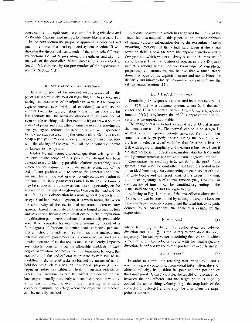
Considering the reaching task, we define the goal of the system in this way: the controller must keep the end-effector on an ideal linear trajectory connecting, at each instant of time, the end-effector and the target point. If the target is moving, this linear trajectory is, of course, time-varying. However, at each instant of time, it can be identified segmenting in the visual field the target and the end-effector.
Referring to Fig. I , motion of the end-effector along the 3- D trajectory can be constrained by nulling the angle B between the end-effector velocity vector v and the ideal trajectory path, denoted by x. Analytically, the angle 0 is defined by the expression
(1)
where h = JL is the unitary vector along the velocity llvll direction and n = is the unitary vector along the ideal trajectory. The unitary vector r, defining the axis about which a rotation aligns the velocity vector with the ideal trajectory direction, is defined by the vector product between h and n
h x n = r sin 0.
h . n = cos B
IIXII
(2)
In order to control the reaching task, variables 0 and r must be derived computing, from visual information, the end- effector velocity, its position in space and the position of the target point. A third variable, the Euclidean distance lixil between the end-effector and the target point, is used to control the approaching velocity (e.g., the amplitude of the end-effector velocity) and to stop the arm when the target point is reached.
Authorized licensed use limited to: University of Sassari. Downloaded on March 03,2010 at 05:01:43 EST from IEEE Xplore. Restrictions apply.
7 34 IEEE TRANSACTIONS ON ROBOTICS AND AUTOMATION, VOL 12, NO 5, OCTOBER 1996
Fig. 1. Frame positions and state variables used in the control task.
that
.
.
Before proceeding to a detailed system description and analysis it is worth to summarize some general assumptions
characterize the proposed approach: The robot manipulator is considered as an ideal position- ing device, with negligible dynamics. The binocular system is "well posed" with respect to
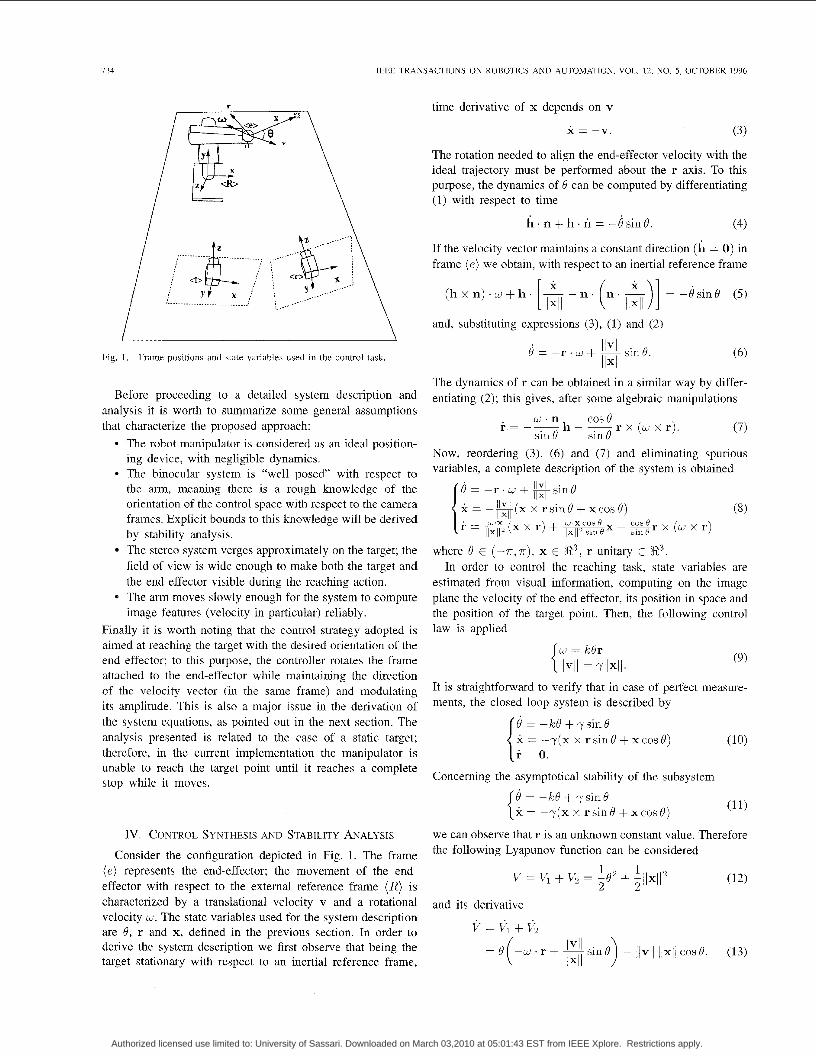
time derivative of x depends on v
x = -v. ( 3 )
The rotation needed to align the end-effector velocity with the ideal trajectory must be performed about the r axis. To this purpose, the dynamics of 0 can be computed by differentiating (1) with respect to time
h . n + h . r i = -)sing. (4)
If the velocity vector maintains a constant direction (h = 0) in frame ( e ) we obtain, with respect to an inertial reference frame
and, substituting expressions (3 ) , (1) and (2)
llvll
llxll 0 = - r . w + -sin6'.
The dynamics of r can be obtained in a similar way by differ- entiating (2); this gives, after some algebraic manipulations
. w'n cos0 r = --h- -r x (w x r). sin 6' sin 6' (7)
Now, reordering (3 ) , (6) and (7) and eliminating spurious variables, a complete description of the system is obtained
4 = -r. w + sin 0 llxll j : = - N ( x x r s i n ~ + x c o s ~ ) IIXII (8) i- = q ( x x r) + -x W ' X cos 0 - s r x (w x r)
IIXII llxll s*n
the arm, meaning there is a rough knowledge of the orientation of the control space with respect to the camera frames. Explicit bounds to this knowledge will be derived by stability analysis. The stereo system verges approximately on the target; the field of view is wide enough to make both the target and the end effector visible during the reaching action. The arm moves slowly enough for the system to compute image features (velocity in particular) reliably.
where 8 E ( -T. T ) , x E R3, r unitary E R3. In order to control the reaching task, state variables are
estimated from visual information, computing on the image plane the velocity of the end effector, its position in space and the position of the target point. Then, the following control
Finally it is worth noting that the control strategy adopted is aimed at reaching the target with the desired orientation of the end effector; to this purpose, the controller rotates the frame attached to the end-effector while maintaining the direction of the velocity vector (in the same frame) and modulating its amplitude. This is also a major issue in the derivation of the system equations, as pointed out in the next section. The analysis presented is related to the case of a static target: therefore, in the current implementation the manipulator is unable to reach the target point until it reaches a complete stop while it moves.
Iv. CONTROL SYNTHESIS AND STABILITY ANALYSIS
Consider the configuration depicted in Fig. 1. The frame ( e ) represents the end-effector; the movement of the end- effector with respect to the external reference frame (R) is characterized by a translational velocity v and a rotational velocity w . The state variables used for the system description are 8, r and x, defined in the previous section. In order to derive the system description we first observe that being the target stationary with respect to an inertial reference frame,
law is applied
(9)
It is straightforward to verify that in case of perfect measure- ments, the closed loop system is described by
(10) r = 0.
Concerning the asymptotical stability of the subsystem
(1 1) 0 = -kQ + ysin6' x = -r(x x r sin 8 + x cos 0)
we can observe that r is an unknown constant value. Therefore the following Lyapunov function can be considered
(12) v = 6 + fi = -82 1 1 + -ilx112
2 2 and its derivative
v = + v 2
- /lvll llxll cos8. (13)
Authorized licensed use limited to: University of Sassari. Downloaded on March 03,2010 at 05:01:43 EST from IEEE Xplore. Restrictions apply.
GROSS0 et NI ROBUST VISUAL SERVOING IN 3-D REACHING TASKS 735
The application of the stability criterion yields
V = -ko2 + 70 sin 0 - yllx112 cos 0 (14)
which negativeness in a neighborhood of the equilibrium point (8 1 0. x = 0) can be easily proved.
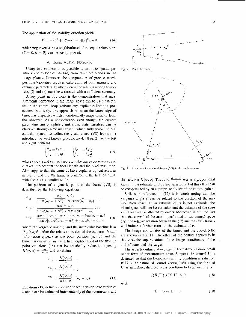
V. USING VISUAL FEATURES Using two cameras it is possible to estimate spatial po-
sitions and velocities starting from their projections in the image planes. However, the computation of precise metric positionshelocities requires calibration of both intrinsic and extrinsic parameters. In other words, the relation among frames (R) . (1) and ( T ) must be estimated with a sufficient accuracy.
A key point in this work is the demonstration that mea- surements performed in the image space can be used directly inside the control loop without any explicit calibration pro- cedure. Intuitively, this approach relies on the knowledge of binocular disparity, which monotonically maps distance from the observer. As a consequence, even though the camera parameters are completely unknown, state variables can be observed through a "visual space" which fully maps the 3-D Cartesian space. To define the visual space (VS) let us first introduce the well known pin-hole model (Fig. 2) for the left and right cameras
where ( ~ 1 , vl) and ( U,, U,) represent the image coordinates and cli takes into account the focal length and the pixel resolution. Also suppose that the cameras have coplanar optical axes, as in Fig. 3, and the VS frame is centered in the fixation point, with the z axis parallel to 2.
The position of a generic point in the frame (VS) is described by the following equations
ab1 - ~ l b 3
sin$(ulu, + a 2 ) + cli cos$(ul - U,)
ab1 - u l b y
sin$(ulu,, + a2) + mcos,$(?~l - U,)
a b 3 tan?/iwl - bl tan$uriL, - bla(ul ~ u..) tan $[sin $ ( u ~ u , + a 2 ) + cos ~ ( 1 1 1 - 71, )]
vs.r = ' U7
3 ' U , VS Y =
(16)
where the vergence angle $ and the interocular baseline b = ( b l , 0, b ~ ) ~ define the relative position of the cameras. Visual information appears as the point position (71,, 7 1 r ) and the binocular disparity (u1 - u ~ ) . In a neighborhood of the fixation point equations (16) can be drastically reduced, imposing K($,b) = & and obtaining
" S Z
'7l T L r s x e ~ K($, b) ,
N
' 71, YC- vs j{($>b) a
Equations (1 7) define a Cartesian space in which state variables Q and r can be estimated independently of the parameter a and
Fig. 2. Pin hole model.
Fig. 3. Location of the visual frame (VS) in the coplanar case
the function K ( $ , b). The ratio acts as a proportional factor in the estimate of the state variable x, but this effect can be compensated by an appropriate choice of the control gain y.
Still, with reference to (17) it is worth noting that the vergence angle ,t,h can be related to the position of the ma- nipulation space. If an estimate of $ is not available, the visual space will not be Cartesian and the estimate of the state variables will be affected by errors. Moreover, due to the fact that the control of the arm is performed in the control space (R) , the relative rotation between the (I?) and the (VS) frames will induce a further error on the estimate of r.
The image coordinates of the target and the end-effector are shown in Fig. 11. The effect of the control applied is in this case the superposition of the image coordinates of the end-effector and the target.
The aspects outlined above can be formalized in more detail under form of measurement error. Suppose the control U is designed so that the Lyapunov stability condition is satisfied. If U is the estimated control vector, built using the form of U as guideline, then the crcm condition to keep stability is
. f ( X , U ) f ( X . 6 ) > 0 (18)
with
U = 0 e U = 0. (19)
Authorized licensed use limited to: University of Sassari. Downloaded on March 03,2010 at 05:01:43 EST from IEEE Xplore. Restrictions apply.
136 IEEE TRANSACTIONS ON ROBOTICS AND AUTOMATION, VOL. 12, NO. 5 , OCTOBER 1996
llxll increase
I Stability
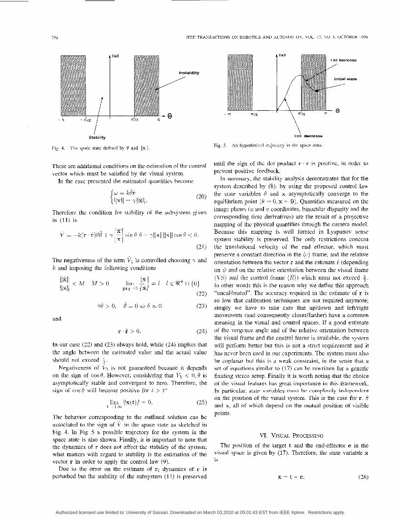
Fig. 4. The space state defined by 6’ and llxll
These are additional conditions on the estimation of the control vector which must be satisfied by the visual system.
In the case presented the estimated quantities become
Therefore the condition for stability of the subsystem given in (11) is
~ I I X I I ~ V = -k ( r . r)6’6’ + y- sin 6’ 6’ - rllxlliixll cos 0 < 0. llxll
(21)
The negativeness of the term VI is controlled choosing y and k and imposing the following conditions
and
In our case (22) and (23) always hold, while (24) implies that the angle between the estimated value and the actual value should not exceed :.
Negativeness of V, is not guaranteed because it depends on the sign of cos 8. However, considering that VI < 0 , 8 is asymptotically stable and convergent to zero. Therefore, the sign of cos0 will become positive for t > t*
lim ((x(t)I( = 0. (25) t++m
The behavior corresponding to the outlined solution can be associated to the sign of V in the space state as sketched in Fig. 4. In Fig. 5 a possible trajectory for the system in the space state is also shown. Finally, it is important to note that the dynamics of r does not affect the stability of the system; what matters with regard to stability is the estimation of the vector r in order to apply the control law (9).
Due to the error on the estimate of q dynamics of r is perturbed but the stability of the subsystem (1 1) is preserved
\ \
IIxII decrease
Fig. 5. An hypothetical trajectory in the space state
until the sign of the dot product r . r is positive, in order to prevent positive feedback.
In summary, the stability analysis demonstrates that for the system described by (8), by using the proposed control law the state variables d and x asymptotically converge to the equilibrium point (0 = 0, x = 0) . Quantities measured on the image planes (U and U coordinates, binocular disparity and the corresponding time derivatives) are the result of a projective mapping of the physical quantities through the camera model. Because this mapping is well formed in Lyapunov sense system stability is preserved. The only restrictions concern the translational velocity of the end effector, which must preserve a constant direction in the ( e ) frame, and the relative orientation between the vector r and the estimate ? (depending on $ and on the relative orientation between the visual frame (VS) and the control frame (R) ) which must not exceed ?j. In other words this is the reason why we define this approach “uncalibrated”. The accuracy required in the estimate of r is so low that calibration techniques are not required anymore; simply we have to take care that upldown and leftlright movements (and consequently closer/farther) have a common meaning in the visual and control spaces. If a good estimate of the vergence angle and of the relative orientation between the visual frame and the control frame is available, the system will perform better but this is not a strict requirement and it has never been used in our experiments. The system must also be coplanar but this is a weak constraint, in the sense that a set of equations similar to (17) can be rewritten for a generic fixating stereo setup. Finally it is worth noting that the choice of the visual features has great importance in this framework. In particular, state variables must be completely independent on the position of the visual system. This is the case for r; 0 and x, all of which depend on the mutual position of visible points.
VI. VISUAL PRQCESSING The position of the target t and the end-effector e in the
visual space is given by (17). Therefore, the state variable x is
Authorized licensed use limited to: University of Sassari. Downloaded on March 03,2010 at 05:01:43 EST from IEEE Xplore. Restrictions apply.
GROSS0 et al.: ROBUST VISUAL SERVOING IN 3-D REACHING TASKS
Encodem
I ........................................................................... i ............................................ : -
131
...............................................................................................................................................................
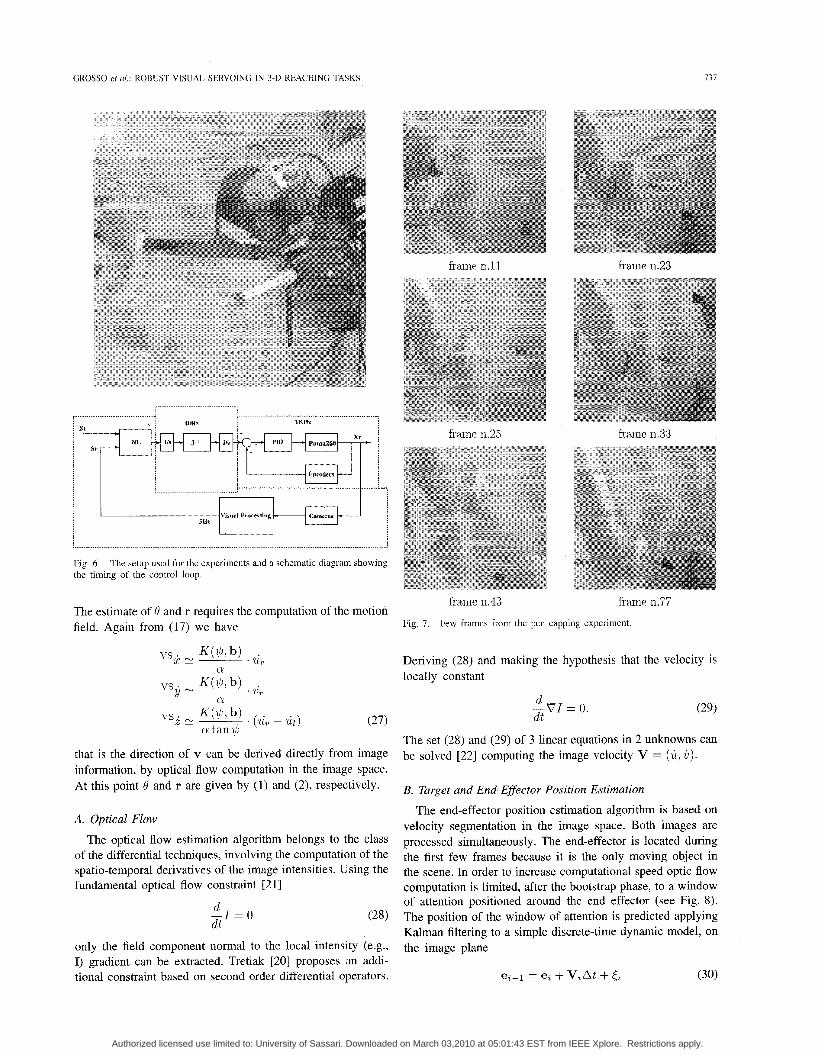
Fig. 6. the timing of the control loop.
The setup used for the experiments and a xhematic diagram showing
The estimate of 0 and r requires the computation of the motion field. Again from (17) we have
cy
that is the direction of v can be derived directly from image information, by optical flow computation in the image space. At this point Q and r are given by (1) and (2), respectively.
A. Optical Flow The optical flow estimation algorithm belongs to the class
of the differential techniques, involving the computation of the spatio-temporal derivatives of the image intensities. Using the fundamental optical flow constraint [21]
d -I = 0 d t
only the field component normal to the local intensity (e.g., I) gradient can be extracted. Tretiak [20] proposes an addi- tional constraint based on second order differential operators.
frame 11.25
Fig. 7. Few frames from the pen capping experiment.
Deriving (28) and making the hypothesis that the velocity is locally constant
d -VI = 0. d t
The set (28) and (29) of 3 linear equations in 2 unknowns can be solved [22] computing the image velocity V = (h, c).
B. Target and End-Effector Position Estimation
The end-effector position estimation algorithm is based on velocity segmentation in the image space. Both images are processed simultaneously. The end-effector is located during the first few frames because it is the only moving object in the scene. In order to increase computational speed optic flow computation is limited, after the bootstrap phase, to a window of attention positioned around the end effector (see Fig. 8). The position of the window of attention is predicted applying Kalman filtering to a simple discrete-time dynamic model, on the image plane
Authorized licensed use limited to: University of Sassari. Downloaded on March 03,2010 at 05:01:43 EST from IEEE Xplore. Restrictions apply.
738 IEEE TRANSACTIONS ON ROBOTICS AND AUTOMATION, VOL. 12, NO. 5, OCTOBER 1996
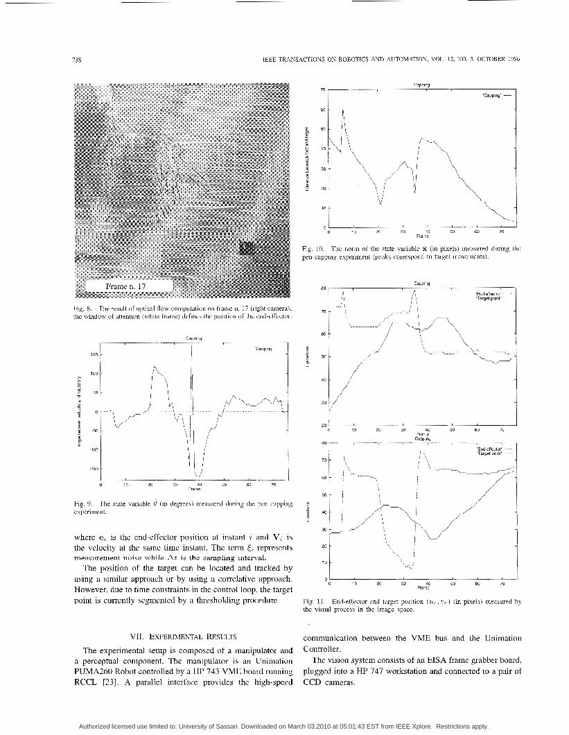
Fig. 8. The result of optical flow computation on frame n. 17 (right camera); the window of attention (white frame) defines thc position of the end-effector.
V 0 10 20 30 40 50 60 70
The state variable 4 (in degrees) measured during the pen capping
Frame
Fig. 9. experiment.
where et is the end-effector position at instant i and V, is the velocity at the same time instant. The term Ct represents measurement noise while At is the sampling interval.
The position of the target can be located and tracked by using a similar approach or by using a correlative approach. However, due to time constraints in the control loop, the target point is currently segmented by a thresholding procedure.
VII. EXPERIMENTAL RESULTS The experimental setup is composed of a manipulator and
a perceptual component. The manipulator is an Unimation PUMA260 Robot controlled by a HP 743 VME board running RCCL [23]. A parallel interface provides the high-speed
0 ' 0
I 10 20 30 40 50 60 70
Frame
Fig. 10. pen capping experiment (peaks correspond to target movements).
The norm of the state variable x (in pixels) measured during the
40v 30
20
0 10 20 30 40 50 60 70 Frame
Fig. 11. the visual process in the image space.
End-effector and target position (ur, U?.) (in pixels) measured by
communication between the VME bus and the Unimation Controller.
The vision system consists of an EISA frame grabber board, plugged into a HP 747 workstation and connected to a pair of CCD cameras.
Authorized licensed use limited to: University of Sassari. Downloaded on March 03,2010 at 05:01:43 EST from IEEE Xplore. Restrictions apply.
GROSS0 et ul.: ROBUST VISUAL SERVOING IN 3-11 REACHING TASKS 739
frmie n.18
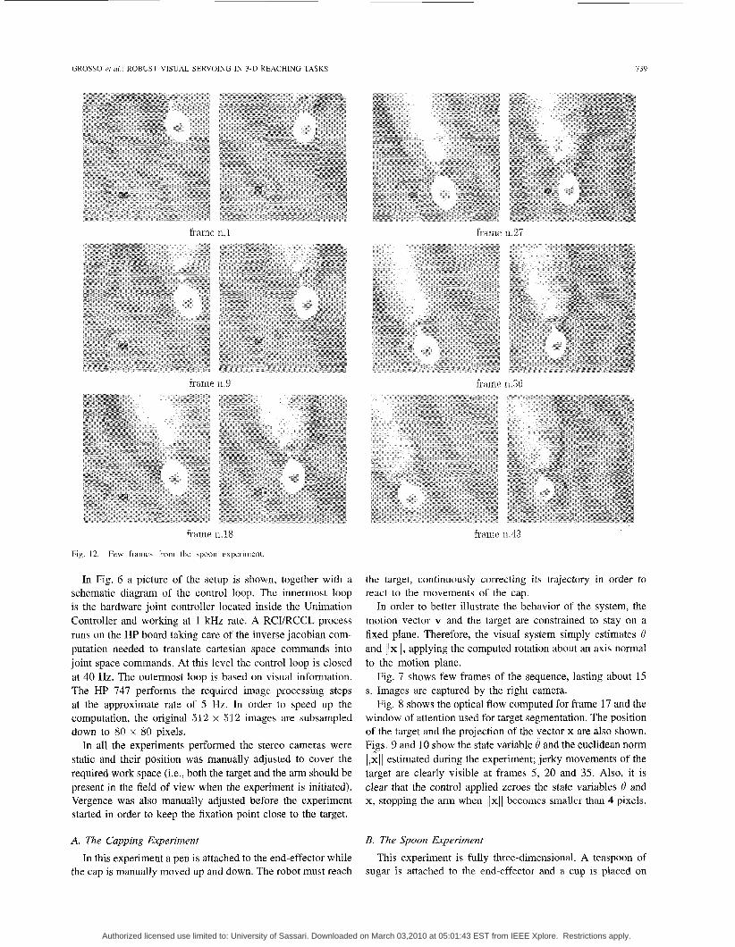
Fig. 12. Few frames from the spoon experiment.
In Fig. 6 a picture of the setup is shown, together with a schematic diagram of the control loop. The innermost loop is the hardware joint controller located inside the Unimation Controller and working at 1 kHz rate. A RCI/RCCL process runs on the HP board taking care of the inverse jacobian com- putation needed to translate Cartesian space commands into joint space commands. At this level the control loop is closed at 40 Hz. The outermost loop is based on visual information. The HP 747 performs the required image processing steps at the approximate rate of 5 Hz. In order to speed up the computation, the original 512 x 512 images are subsampled down to 80 x 80 pixels.
In all the experiments performed the stereo cameras were static and their position was manually adjusted to cover the required work space (i.e., both the target and the arm should be present in the field of view when the experiment is initiated). Vergence was also manually adjusted before the experiment started in order to keep the fixation point close to the target.
A. The Capping Experiment
In this experiment a pen is attached to the end-effector while the cap is manually moved up and down. The robot must reach
the target, continuously correcting its trajectory in order to react to the movements of the cap.
In order to better illustrate the behavior of the system, the motion vector v and the target are constrained to stay on a fixed plane. Therefore, the visual system simply estimates 6' and IlxII, applying the computed rotation about an axis normal to the motion plane.
Fig. 7 shows few frames of the sequence, lasting about 15 s. Images are captured by the right camera.
Fig. 8 shows the optical flow computed for frame 17 and the window of attention used for target segmentation. The position of the target and the projection of the vector x are also shown. Figs. 9 and 10 show the state variable 8 and the euclidean norm ilxll estimated during the experiment; jerky movements of the target are clearly visible at frames 5, 20 and 35. Also, it is clear that the control applied zeroes the state variables 0 and x, stopping the arm when ~~x~~ becomes smaller than 4 pixels.
B. The Spoon Experiment
This experiment is fully three-dimensional. A teaspoon of sugar is attached to the end-effector and a cup is placed on
Authorized licensed use limited to: University of Sassari. Downloaded on March 03,2010 at 05:01:43 EST from IEEE Xplore. Restrictions apply.
740
50
45
40
IEEE TRANSACTIONS ON ROBOTICS AND AUTOMATION, VOL 12, NO 5 , OCTOBER 1996
'spoon dist' ~
-
-
SpOO"
180 'SPOM ang' -
I n 5 i n 15 zn 25 30 35 40
Frame
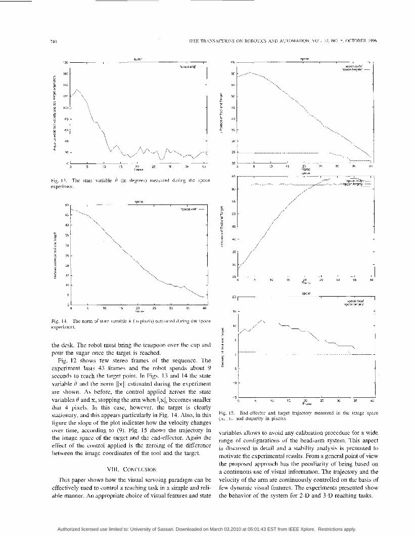
Fig. 13. experiment.
The state variable I? (in degrees) measured during the spoon
35 -
30 -
25 -
20 -
15 -
10 - -----. 1
1 0 5 10 15 20 25 30 35 40
Flame
Fig. 14. experiment.
The norm of Etate variable x (in pixels) measured during the spoon
the desk. The robot must bring the teaspoon over the cup and pour the sugar once the target is reached.
Fig. 12 shows few stereo frames of the sequence. The experiment lasts 43 frames and the robot spends about 9 seconds to reach the target point. In Figs. 13 and 14 the state variable 8 and the norm llx(l estimated during the experiment are shown. As before, the control applied zeroes the state variables 19 and x, stopping the arm when / (x(( becomes smaller that 4 pixels. In this case, however, the target is clearly stationary, and this appears particularly in Fig. 14. Also, in this figure the slope of the plot indicates how the velocity changes over time, according to (9). Fig. 15 shows the trajectory in the image space of the target and the end-effector. Again the effect of the control applied i s the zeroing of the difference between the image coordinates of the tool and the target.
VIII. CONCLUSION
This paper shows how the visual servoing paradigm can be effectively used to control a reaching task in a simple and reli- able manner. An appropriate choice of visual features and state
I 0 5 10 15 20 25 30 35 40
Frame
20 'spoon tO0lZ' -
'spamtargetz' ----
-5 t 1
-15 5 10 15 20 25 30 35 40
Frame
15. End-effector and tarEet tralectory measured in the image space ~~
( U ~ . . 7'7- and disparity in pixels).
variables allows to avoid any calibration procedure for a wide range of configurations of the head-arm system. This aspect is discussed in detail and a stability analysis is presented to motivate the experimental results. From a general point of view the proposed approach has the peculiarity of being based on a continuous use of visual information. The trajectory and the velocity of the arm are continuously controlled on the basis of few dynamic visual features. The experiments presented show the behavior of the system for 2-D and 3-D reaching tasks.
Authorized licensed use limited to: University of Sassari. Downloaded on March 03,2010 at 05:01:43 EST from IEEE Xplore. Restrictions apply.
GKOSSO et ul.: R O B U S 1 VISUAL SEKVOING IN 3-D REACHING TASKS 74 1
The approach presented here is still limited by the fact that we only partially exploit the knowledge of the self-generated motor act (the direction of the translational velocity) to tune the visual processing and by the fact that the position of the cameras in space cannot be actively controlled. Interesting extensions (and possibly simplifications) can be achieved by controlling, not only the motion of the arm, but also the position and orientation of the cameras. It is worth noting, in fact, that our calibration-less approach will hold also if the camera moves simultaneously with the arm (apart, of course, the non trivial added problem of segmenting a moving object from a moving camera). This potentiality can be of great importance to keep the visual field oriented toward the target in case of moving targets and/or if the cameras are mounted on a moving platform.
In terms of potential applications, the proposed approach could be very interesting, particularly in all cases in which accurate calibration is impossible or time consuming. For instance, in all applications in which the vision system and the arm are not rigidly connected (mobile vehicles under visual surveillance, docking stations for carry and load systems).
Work is in progress for the implementation of a fully integrated head-arm system, in which the reaching task will exploit basic eye-head movements like tracking, vergence and saccades.
ACKNOWLEDGMENT
The authors thank G. Cannata and A. Caiti for their useful comments on stability analysis.
REFERENCES
11 j H. C. Longuet-Higgins, “A computer algorithm for rcconstructing a scene from two projcctions,” Nufitre, vol. 293, pp. 133-1 35, I98 I .
121 1. Sobel, “On calibrating computer controllcd cameras for perceiving 3-D scenes,” Art$ Intell., vol. 5 , pp. 185-198, 1974.
131 B. Espiau, F. Chaumette, P. Rives, and B. Espiau, “Positioning of a robot with respect to an objccl, tracking it and estimating its velocity by visual servoing,” in Pruc. 1991 h t . Conf on Robotics cmd Automcltion,
141 R. Bajcsy and C. Tsikos, “Perception via manipulation,” in Proc. @/lie Int. Svmp. & Exposition on Robots, Sydney, Australia, Nov. 6-10, 1988, pp. 237-244.
[SI D. H. Ballard, “Animate vision,”Arri$ Intell., vol. 48, pp. 57-86, 1991. [6] Y. Aloimonos, Active Vision as a Meihodology. Hillsdale, NJ: Lawren-
nce Erlbaum, 1993. [7] A. J. Koivo and N. Houshangi, “Real time vision feedback for servoing
robotic manipulator with self-tuning controller,” IEEE Trans. Syst., Man, Cybern., vol. 21, pp. 134-142, Jan./Feb. pp. 1991.
[8] B. Espiau, F. Chaumette, and P. Rives, “A new approach to visual servoing in robotics,” IEEE Trans. Robot. Automat., vol. 8, no. 3, pp.
1991, pp. 248-2253,
~~
313-326, June 1992. 191 N. P. Papanikolopoulos and P. K. Khosla, “Adaptive robotic visual _ -
tracking: theory and experiments,” IEEE Truns. Automa/. Confr., vol. 38, no. 3, pp. 429445, 1993.
[ 101 A. Castano and S. Hutchinson, “Visual compliance: Task-directed visual servo control,” IEEE Trans. Robot. Automut., vol. 10, no. 3, 1994.
ing action,” in Active Perception, Y. Aloimonos, Ed. Hillsdale, NJ: Lawrennce Erlbaum, 1993, pp. 151-190.
[I21 W. Jang and Z. Bien, “Feature-based visual servoing of an eye-in-band robot with improved tracking performance,” in Pruc. 1991 Int. Conf on Robotics und Automation, I99 I , pp. 2254-2260.
[I31 N. P. Papanikolopoulos and P. K. Khosla, ‘Selection of features and evaluation of visual measurements for 3-D robotic visual tracking,” in
[ I 11 G. Sandini, F. Gmdolfo, E. Grosso, and M. Tiatarclli, “Vision dur-
141 C. Samson, M. Le Borgue, and B. Espiau, Robot Control: The Task Funclion Approach.
1 S] M. Salganicoff, G. Metta, A. Oddera, and C . Sandini, “A dircct approach to vision guided manipulation,” in Pruc.. /CAR-93, Tokyo, Japan, Nov.
161 G. Sandini, F. Gandolfo, G. Metta, and A. Oddera, “The role of vision in two-arm manipulation,” Prot. Con$ on Computer Vision and Puttern Recognition, New York, June 1993, pp. 622-624.
1171 B. H. Yoshimi and P. K. Allen, “Active, uncalibrated visual servoing,” in Proc. 1994 Int. Con5 on Robotics andAutumution, 1994, pp. 156-161.
[ 181 A. Conkie and P. Chongstitvatana, “An uncalibrated stereo visual servo system,’’ in Pruc. 1990 Conf: on British Machine Vision, 1990, pp. 277-280.
1191 G. Casalino et al., “Closed loop steering for unicycle like vehicles: A simple Lyapunov like approach,” SYROCO. 1994.
1201 0. Tretiak and L. Pastor, “Velocity estimation from image sequences with second order differential operators,” in Proc.. Inr. Cunf: on Pattern Recognition, Montreal, Qukbec, Canada, 1984, pp. 16-19.
[21] B. K. P. Horn, Robot Vision. 1221 M. Tistarclli, “Multiple constraints for optical flow.” in Proc. 3rd
European Conference on Computer Vision, Stockholm, Sweden, May
1231 J. Lloyd and V. Hayward, Reul-7ime 7?ajectory Generation in Multi- RCCL, McGill University TR, Montreal, Quebec, Canada, 1992.
1241 R. L. Andersson, A Robor Ping-Pong Player. Cambridge, MA: MIT Press, 1988.
1251 D. Raviv and M. Herman, “Visual servoing from 2-D image cues,” in A c h e Perception, Y. Aloimonos, Ed. Hillsdale, NJ: Lawrence Erlbaum, 1993, pp. 191-226.
[26] P. Allcn, “Object recognition using vision and touch,” Ph.D. Disserta- tion, University of Pennsylvania, Philadelphia, 1985.
[27] E. Grosso and D. H. Ballard, “Head-centered orientation strategies in animate vision,” in 3rd Int. Conf: on Computer Vision, Berlin, Germany,
Oxford, U.K.: Clarendon, 1991.
1993, pp. 133-140.
Cambridge, MA: MIT Press, 1986.
2-6, 1994, pp. 61-70.
1993, pp. 395-402. [281 J. J. Craig, Introduction tu Roborics: Mechanics und Control. Reading, . -
MA: Ad&on-Wesley, 1989.
Munipulator,s. New York: Macmillan, 1993.
York: Wiley, 1989.
1291 F. I-.. Lewis, C. T. Abdallah, and D. M. Dawson, Conlrol of Robot
[30] M. Spong and M. Vidyasagar, Robot Dynamics and Control. New
Enrico Grosso was born in Serravalle Scrivia, Italy, on November 29, 1963. He rcceived the degree in electronic engineering from the University of Genoa in 1988, and the Ph.D. in computer science and electronic engineering in 1993, also from the University of Genoa.
Since 1988 he has been involved as project in- vestigator and task manager in various ESPRIT projects funded by the European Community. In 1900, he was with the National Institute of Scientific Research LIFIA, Grenoble, France, and in 1992, he
was a visiting scientist at the Department of Computer Science, University of Rochester, Rochester, NY. He is currently assistant professor, Department of Communication, Computer, and System Sclence, University of Genoa Hi5 main research intereats cover biological and artificial vision, visuo-motor coordination and robotics.
Giorgio Metta was born in Cagliari, Italy, in 1970 He received the degree (magna cum laude) in elec- tronic engineering from the University of Genoa, Italy, in 1994, discussing a thesis on visual servoing and robot manipulation
Since 1991, he has been with the LIRA Labo- ratory, DIST-University of Genoa, where he devel- oped real time applications under RCVRCCL For three months in 1995, he was with the Department of Computer Science, Leeds University, England, funded by a grant from the EU-HCM SMART
prolect. He 15 currently doing natlonal service as an officer in the Italian Proc. 8th Int. Symp. on Intelligent Conlrol, 1993, pp. 320-325. Naiy Chief Staff, Rome.
Authorized licensed use limited to: University of Sassari. Downloaded on March 03,2010 at 05:01:43 EST from IEEE Xplore. Restrictions apply.
142 IEEE TRANSACTIONS ON ROBOTICS AND AUTOMATION, VOL. 12, NO. 5 , OCTOBER 1996
Andrea Oddera was born in Savona, Italy, in 1969 He received the degree (magna cum laude) in electronic engineering from the Univerrity of Genod, Italy, in 1994
From 1991 to 1994, he was with the LIRA Lab, DIST-University of Genoa, developing software for motion analysis and real-time robot control He 15 currently with AITEK S
Giulio Sandini was born on September 7, 1950, in Correggio, Italy He received a degree in electronic engineering Tiom the University of Genoa, Italy.
Since 1976 he has worked on models of the viwal system and on electrophysiology of the cat viaual cortex at the Laboratorio di Neurofisiologia del CNR di Pisa In 1978 dnd 1979, he was a Visiting Scientist at the Harvard Medical School, Boston, MA, developing a system for topographic analysis of brain electrical activity Since 1980 he has worked on image proLesing and coinputer
vision particularly in the areas ot low-level vision and feature extraction, at thc Department of Communicdtion, Compute, and Systems Sclence of the Univeisity of Genoa, where he 17 currently an Associate Professor
Prof Sandini served as General Chdirman for the 2nd European Conference on Coinputer Vision
Authorized licensed use limited to: University of Sassari. Downloaded on March 03,2010 at 05:01:43 EST from IEEE Xplore. Restrictions apply.
Related Documents


![Visual Servoing-based Navigation for Monitoring Row-Crop ... · Traditionally, visual servoing techniques [11] are used for controlling robotic arms and manipulators. These techniques](https://static.cupdf.com/doc/110x72/606d9bc1175fff2c42161cd5/visual-servoing-based-navigation-for-monitoring-row-crop-traditionally-visual.jpg)


