IEEE TRANSACTIONS ON AUTOMATIC CONTROL, VOL. 48, NO. 3, MARCH 2003 413 Robust Nonlinear Motion Control of a Helicopter Alberto Isidori, Fellow, IEEE, Lorenzo Marconi, Member, IEEE, and Andrea Serrani, Member, IEEE Abstract—We consider the problem of controlling the vertical motion of a nonlinear model of a helicopter, while stabilizing the lateral and horizontal position and maintaining a constant attitude. The reference to be tracked is given by a sum of a constant and a fixed number of sinusoidal signals, and it is assumed not to be available to the controller. This represents a possible situation in which the controller is required to synchronize the vehicle motion with that of an oscillating platform, such as the deck of a ship in high seas. We design a nonlinear controller which combines recent results on nonlinear adaptive output regulations and robust sta- bilization of systems in feedforward form by means of saturated controls. Simulation results show the effectiveness of the method and its ability to cope with uncertainties on the plant and actuator model. Index Terms—Nonlinear systems, output regulation, robust con- trol, saturated controls, vertical takeoff and landing. I. INTRODUCTION A UTOPILOT design for helicopters is a challenging testbed in nonlinear feedback design, due to the nonlinearity of the dynamics and the strong coupling between the forces and torques produced by the vehicle actuators, as witnessed by a good deal of important contributions in the last twenty years (see [1]–[8] to mention a few). A helicopter is, in general, an under- actuated mechanical system, that is, a system possessing more degrees of freedom than independent control inputs. Partial (i.e, input-output) feedback linearization techniques are not suitable for the control of such a system, because the resulting zero-dy- namics are only critically stable. Moreover, the model may be affected by large uncertainties and unmodeled dynamics, and this also renders any design technique based on exact cancella- tion of nonlinear terms poorly suited. In this paper, we address the design of an internal-model based autopilot for a helicopter. The control goal is to have the vertical position of the helicopter tracking an exogenous reference trajectory, while its longitu- dinal and lateral position, as well as its attitude, are stabilized to a constant configuration. The reference trajectory which is to be tracked is a superposition of a finite number of sinusoidal Manuscript received November 15, 2001; revised June 30, 2002 and October 7, 2002. Recommended by Associate Editor J. Huang. This work was supported in part by the Office of Naval Research under Grant N00014-99-1-0697, by the Air Force Office of Scientific Research under Grant F49620-98-1-0170, and by MURST. A. Isidori is with the Dipartimento di Informatica e Sistemistica, Università di Roma “La Sapienza,” 00184 Rome, Italy, and with the Department of Systems Science and Mathematics, Washington University, St. Louis MO 63130 USA (e-mail: [email protected]). L. Marconi is with the Dipartimento di Elettronica, Informatica e Sis- temistica, Università degli Studi di Bologna, Bologna 40136, Italy. (e-mail: [email protected]) A. Serrani is with the Department of Electrical Engineering, The Ohio State University, Columbus, OH 43210 USA (e-mail: [email protected] state.edu). Digital Object Identifier 10.1109/TAC.2003.809147 signals of unknown frequency, amplitude and phase. This situa- tion corresponds, for instance, to the case in which a helicopter is required to land autonomously on the deck of a ship subject to wave-induced oscillations. The trajectory in question is not available in real time: rather only the tracking error and its rate of change are assumed to be available in real time. A similar problem has been previously considered and solved for a sim- plified model of a VTOL aircraft [9]. With respect to the former, however, the present case is more challenging, due to the higher complexity of the vehicle dynamics which renders the stabiliza- tion onto the desired trajectory a difficult task. We propose a so- lution which combines recent results on nonlinear adaptive reg- ulation and robust stabilization of systems in feedforward form by means of saturated controls. The focus of this paper is mostly on the stabilization technique. Due to the intrinsic robustness of the method, we expect the controller to perform satisfactorily despite the effect of parametric uncertainties and unmodeled dy- namics. As a matter of fact, we design our controller on the basis of a simplified model, and show the effectiveness of our method on a more complete model by means of computer simulations. Complete model and simplified model are precisely those pro- posed in [2]. Our design techniques assume full availability of all state variables in appropriate reference frames; namely ver- tical, longitudinal, lateral errors (and their rates of change) as well as attitude (and its rate of change). This makes it possible to develop a semiglobal robust stabilization scheme, thus circum- venting the problem that, for certain selections of output vari- ables, the controlled system is nonminumum phase (as shown in [2]). The paper is organized as follows: in Section II the ve- hicle model is introduced. In Section III we describe the design problem, and in Sections IV and V we present the controller de- sign. Simulation results are illustrated and briefly discussed in Section VI. Finally, we draw some conclusions in Section VII. II. HELICOPTER MODEL A mathematical model of the helicopter dynamics can be de- rived from Newton–Euler equations of motion of a rigid body in the configuration space . Fix an inertial coordinate frame in the euclidean space, and fix a coordi- nate frame attached to the body. Let denote the position of the center of mass of the rigid body with respect to the origin of , and let denote the ro- tation matrix mapping vectors expressed in coordinates into vectors expressed in coordinates. The translational velocity of the center of mass of the body and its angular ve- locity (both expressed in ) by definition satisfy (1) 0018-9286/03$17.00 © 2003 IEEE

Welcome message from author
This document is posted to help you gain knowledge. Please leave a comment to let me know what you think about it! Share it to your friends and learn new things together.
Transcript

IEEE TRANSACTIONS ON AUTOMATIC CONTROL, VOL. 48, NO. 3, MARCH 2003 413
Robust Nonlinear Motion Control of a HelicopterAlberto Isidori, Fellow, IEEE, Lorenzo Marconi, Member, IEEE, and Andrea Serrani, Member, IEEE
Abstract—We consider the problem of controlling the verticalmotion of a nonlinear model of a helicopter, while stabilizing thelateral and horizontal position and maintaining a constant attitude.The reference to be tracked is given by a sum of a constant anda fixed number of sinusoidal signals, and it is assumed not to beavailable to the controller. This represents a possible situation inwhich the controller is required to synchronize the vehicle motionwith that of an oscillating platform, such as the deck of a ship inhigh seas. We design a nonlinear controller which combines recentresults on nonlinear adaptive output regulations and robust sta-bilization of systems in feedforward form by means of saturatedcontrols. Simulation results show the effectiveness of the methodand its ability to cope with uncertainties on the plant and actuatormodel.
Index Terms—Nonlinear systems, output regulation, robust con-trol, saturated controls, vertical takeoff and landing.
I. INTRODUCTION
A UTOPILOT design for helicopters is a challenging testbedin nonlinear feedback design, due to the nonlinearity of
the dynamics and the strong coupling between the forces andtorques produced by the vehicle actuators, as witnessed by agood deal of important contributions in the last twenty years (see[1]–[8] to mention a few). A helicopter is, in general, an under-actuated mechanical system, that is, a system possessing moredegrees of freedom than independent control inputs. Partial (i.e,input-output) feedback linearization techniques are not suitablefor the control of such a system, because the resulting zero-dy-namics are only critically stable. Moreover, the model may beaffected by large uncertainties and unmodeled dynamics, andthis also renders any design technique based on exact cancella-tion of nonlinear terms poorly suited. In this paper, we addressthe design of an internal-model based autopilot for a helicopter.The control goal is to have the vertical position of the helicoptertracking an exogenous reference trajectory, while its longitu-dinal and lateral position, as well as its attitude, are stabilizedto a constant configuration. The reference trajectory which isto be tracked is a superposition of a finite number of sinusoidal
Manuscript received November 15, 2001; revised June 30, 2002 and October7, 2002. Recommended by Associate Editor J. Huang. This work was supportedin part by the Office of Naval Research under Grant N00014-99-1-0697, by theAir Force Office of Scientific Research under Grant F49620-98-1-0170, and byMURST.
A. Isidori is with the Dipartimento di Informatica e Sistemistica, Università diRoma “La Sapienza,” 00184 Rome, Italy, and with the Department of SystemsScience and Mathematics, Washington University, St. Louis MO 63130 USA(e-mail: [email protected]).
L. Marconi is with the Dipartimento di Elettronica, Informatica e Sis-temistica, Università degli Studi di Bologna, Bologna 40136, Italy. (e-mail:[email protected])
A. Serrani is with the Department of Electrical Engineering, The OhioState University, Columbus, OH 43210 USA (e-mail: [email protected]).
Digital Object Identifier 10.1109/TAC.2003.809147
signals ofunknownfrequency, amplitude and phase. This situa-tion corresponds, for instance, to the case in which a helicopteris required to landautonomouslyon the deck of a ship subjectto wave-induced oscillations. The trajectory in question is notavailable in real time: rather only the tracking error and its rateof change are assumed to be available in real time. A similarproblem has been previously considered and solved for a sim-plified model of a VTOL aircraft [9]. With respect to the former,however, the present case is more challenging, due to the highercomplexity of the vehicle dynamics which renders the stabiliza-tion onto the desired trajectory a difficult task. We propose a so-lution which combines recent results on nonlinear adaptive reg-ulation and robust stabilization of systems in feedforward formby means of saturated controls. The focus of this paper is mostlyon the stabilization technique. Due to the intrinsic robustness ofthe method, we expect the controller to perform satisfactorilydespite the effect of parametric uncertainties and unmodeled dy-namics. As a matter of fact, we design our controller on the basisof a simplified model, and show the effectiveness of our methodon a more complete model by means of computer simulations.Complete model and simplified model are precisely those pro-posed in [2]. Our design techniques assume full availability ofall state variables in appropriate reference frames; namely ver-tical, longitudinal, lateral errors (and their rates of change) aswell as attitude (and its rate of change). This makes it possible todevelop a semiglobal robust stabilization scheme, thus circum-venting the problem that, for certain selections of output vari-ables, the controlled system is nonminumum phase (as shownin [2]). The paper is organized as follows: in Section II the ve-hicle model is introduced. In Section III we describe the designproblem, and in Sections IV and V we present the controller de-sign. Simulation results are illustrated and briefly discussed inSection VI. Finally, we draw some conclusions in Section VII.
II. HELICOPTERMODEL
A mathematical model of the helicopter dynamics can be de-rived from Newton–Euler equations of motion of a rigid body inthe configuration space . Fix an inertialcoordinate frame in the euclidean space, and fix a coordi-nate frame attached to the body. Letdenote the position of the center of mass of the rigid body withrespect to the origin of , and let denote the ro-tation matrix mapping vectors expressed incoordinates intovectors expressed in coordinates. The translational velocity
of the center of mass of the body and its angular ve-locity (both expressed in ) by definition satisfy
(1)
0018-9286/03$17.00 © 2003 IEEE

414 IEEE TRANSACTIONS ON AUTOMATIC CONTROL, VOL. 48, NO. 3, MARCH 2003
where
Moreover
(2)
where is the external wrench in body-fixed co-ordinates and and the mass and the inertia tensor of thebody. We will parametrize the group of rotation matrices bymeans of unit quaternions , where and
denote respectively the scalar and the vectorparts of the quaternion, satisfying the constraint
Accordingly, the rotation matrix is given as
(3)The second equation in (1) is then replaced by the quaternionpropagation equation
while the motion of the center of mass of the rigid body is ex-pressed in inertial coordinates as
(4)
In the specific case of a helicopter, the wrench is pro-vided by the forces and torques generated by the rotors and theaerodynamic forces. Following [2], the thrusts generated by themain rotor and the tail rotor are denoted by and , respec-tively. The main rotor shaft is directed along the bodyaxis,while the tip path plane of the main rotor is tilted by an angle
around the axis and by an anglearound the axis. Theoverall control input is provided by the vector .
The expressions of and in terms of the four componentsof the control vector , the mechanical parametersand the aerodynamic coefficients can be found, for instance, in[2]. In particular, following [2], since the tilt anglesand aresmall, we let
(5)
Also, we neglect the contribution of along the directionand we assume that the contribution of and along thedirection is matched by that of , thus obtaining the followingsimplified model for :
(6)
Fig. 1. Model of the approximated system dynamics.
As far as the external torque is concerned, under the previoushypotheses, it is seen from [2] that
(7)
in which and are, respectively, a matrix and avector of affine functions of the thrust , whose coefficientsdepend on the geometry of the helicopter and on the coefficientswhich characterize the aerodynamic forces. A sketch of the po-sition/attitude dynamics is reported in Fig. 1.
One of the goals of the paper is to design a controller able todeal with possibly large parameter uncertainties, including themass of the vehicle, its inertia tensor, and the aerodynamiccoefficients in (7). Collecting all possible parameters subject touncertainty in a single vector, we let stand for its nominalvalue and for the additive uncertainty. It is assumedthat , a given compact set. Accordingly, we set
and, bearing in mind the fact that and are func-tions of
(8)
with obvious meaning of the subscripts.
III. PROBLEM STATEMENT
The goal of this paper is the design of an autopilot able tosecure smooth landing of the helicopter on an oscillating plat-form in uncertain conditions. The considered setup represents apossible scenario in which a helicopter is required to perform asmooth landing on a deck of a ship which, due to wave motion, issubject to large vertical oscillation. The control objective can beconveniently divided into two separate tasks: the first is the syn-chronization of the vertical motion of the helicopter with that ofthe deck at a given distance. Once synchronization has beenachieved, the second task is to provide a smooth landing, lettingthe vertical offset decay to zero. Clearly, the crucial part is thedesign of a controller to accomplish the first task. The problembecomes quite challenging if the information available for feed-back is provided by passive sensors only, yielding the relativeposition between the helicopter and the deck. If this is the case,the vertical reference trajectory to be tracked by the helicopteris not available, but must be estimated in real time by processing

ISIDORI et al.: ROBUST NONLINEAR MOTION CONTROL OF A HELICOPTER 415
the synchronization error. This trajectory, denoted in what fol-lows by , is modeled as the sum of a fixed number of si-nusoidal signals ofunknownamplitude, phase and frequency,namely as
(9)
In this setting, the uncertainty on the reference trajectoryconsists in uncertainty on the exact value of the parameters
, . Consequently, one of the maingoals to be accomplished in the design is to let the center ofmass of the helicopter asymptotically track, as accurately aspossible, the reference motion
(10)
It is also appropriate to require that the vehicle’s attitude asymp-totically tracks, as accurately as possible, the constant refer-ence , which corresponds to the following possiblechoice for the quaternion1
(11)
The problem of having to track can be naturallycast in the framework ofnonlinear adaptive output regulationtheory (see [11], [12]), as the signal is generated by alinear time-invariantexosystem
in which
with
and , with defined in an obvious way. Ascustomary, we assume that the values ofrange over agiven compact set. Note that the role of the parameters
of (9) is played by the initial con-dition of the exosystem. As far as the tracking goal for
, , and is concerned, we seek to obtainultimateboundednessby arbitrarily small bounds. Setting
the design problem can be cast as follows: given any (arbitrarilysmall) number , design a smooth dynamic controller ofthe form
1It is worth stressing that this desired attitude configuration is compatible withthe steady state requirement (10) because we are assuming the simplified model(6) for the force generation. In the general case, assuming the force generationmodel as presented in [2], the desired motion (10) is achieved with a steady stateattitude motion different from (11), as described in [10].
such that the tracking objectives
and for all
are attained within a semiglobal domain of attraction (that is,from initial conditions for the plant states in an arbitrarily largecompact set), for all admissible values of the parameters of theplant and the exosystem. It is worth noting that the controller isallowed to process the tracking errorof the center of massand its derivative , but not the state of the exosystemand the vertical position . Finally, note that the steady-statevalue of the main thrust needed to keep the helicopter onthe reference trajectory (10) and (11) is given by
. Since we require to be positive, we musthave
(12)
which gives an upper bound to the admissible initial conditionsof the exosystem.
IV. STABILIZATION OF THE VERTICAL ERRORDYNAMICS
The first step in the regulator design is the computation ofthe feedforward control signal that must be imposed to achievezero error in steady state. In the terminology of output regula-tion theory, this amounts in solving theregulator equationsforthe problem under investigation (see [10], [11]). To this end,consider the equation for , readily obtained from (1), (6),and (3)
To compensate for the nominal value of the gravity force, let uschoose the preliminary control law
(13)
where , the function is the standard saturationfunction
and is an additional control to be defined. The equation for thevertical dynamics is described by
(14)
where2
From this, it is concluded that, if is small so that, the input needed to keep is simply (recall that
)
(15)
The steady-state behavior of is the superposition of a termmeant to enforce the vertical reference acceleration and a termmeant to compensate the residual gravity force.
2Note that2q + 2q � c implies� (q) = 1.
416 IEEE TRANSACTIONS ON AUTOMATIC CONTROL, VOL. 48, NO. 3, MARCH 2003
It is clear that, as depends on unknown parameters andon the unmeasurable state, the steady-state control (15)is notdirectly implementable as a “feedforward” control. However, itcan be asymptotically reproduced by means of a linear internalmodel, as is a linear function of . Accordingly, we choosethe control as the sum of a stabilizing control and the output ofan internal model, i.e., . The internal model willbe designed on the basis ofadaptive output regulation theory(see [9] and [12]). In fact, (14) is a two-dimensional systemhaving relative degree 2. Hence, the hypotheses presented in[12] for the design of an adaptive internal model, hold. Definethe observable pair as
in which
and note that, by construction, the map
satisfies, for every and , theimmersion condition
(16)
If the vector was known precisely, the matrices andcould be directly used for the design of the internal model. Con-versely, if is not known, a further step is needed. Letbe a
Hurwitz matrix and be vector such thatthe pair is controllable. Then, using standard passivityarguments, it is easy to show that there always exists amatrix such that the pair
(17)
is controllable, and the matrix is Hurwitz. From [12], it isknown that, for any vector , there exists arow vector , of the form
such that the pair is similar to the pair. As a consequence, there exists a map
that satisfies, for every and , the immersioncondition
(18)
Denote now by and the third components of the vectorsand , namely
and consider, as an internal model for our problem, the system
where
in which , and is a row vector.The control system is rewritten in the form
(19)
with . In case the vector is known, we set. Otherwise, we consider to be a vector of parameter
estimates to be adapted, and we choose the update law (see [12])
(20)
with and positive design parameters. The control lawisthen completed choosing thehigh-gainstabilizing feedback
(21)
where is a design parameter. Changing coordinates as
(22)
and letting , the , , dynamics in the newcoordinates read as
(23)
where . This system, setting
(24)
can be rewritten in the form
(25)
Note that the dependence onof the vector fields andarises from the dependence onof the term in
, in turn induced by the dependence onof . Following [9]and [12], it can be shown that, for a sufficiently large, system
(26)
(or, what is the same, system (23),if is sufficiently small sothat ) has a globally asymptotically stable equilibriumat for some which, in turn,

ISIDORI et al.: ROBUST NONLINEAR MOTION CONTROL OF A HELICOPTER 417
coincides with the origin in case all the modes of the exosystemare excited. Without loss of generality, we henceforth assumethat this is the case.
This result concludes the stabilization of the vertical dy-namics. In particular, in case the attitude is kept sufficientlyclose to the desired one so that , the -ordercontroller (13), (19) and (21) with adaptation law (20) is able tosteer asymptotically the vertical error to zero. In Sections Vand VI we will show how to design a control law for the input
to simultaneously achieve the condition in finitetime, and stabilize the lateral and longitudinal dynamics.
V. DESIGN OF THESTABILIZER
A. Lateral and Longitudinal Dynamics
We start by deriving the expression of the lateral and longitu-dinal dynamics resulting from the choice of the main thrustperformed in Section IV. First, note that the term
reads as
which, keeping in mind the definition of in (22) and (18),yields
(27)
where
(28)
Note that, for all
(29)
Bearing in mind (4), (6), we obtain the following expression forthe longitudinal dynamics:
(30)
where
(31)
(32)
Note that we have treated the presence of the forcing termas a time-varying entry, while plays the role of a boundedtime-varying coefficient. Likewise, the lateral dynamics can beput in the form
(33)
where
sat(34)
Fig. 2. Overall approximated system dynamics.
The dynamics are viewed as a system interconnected tothe attitude and vertical dynamics, according to the structuredepicted in Fig. 2. Basically, the choice of the control inputable to stabilize the overall system will rely upon the followingconsiderations. We look at the subsystem as a systemwith “virtual control” and exogenous input . The latter, ac-cording to the results presented in Section IV and by virtue of(28) and (29), is an asymptotically vanishing signal,providedthat the attitude variable is kept sufficiently smallby means ofthe control input . In the light of this, the control law willbe designed on one hand to forceto assume sufficiently smallvalues so that in finite time and, on the other hand, torender the subsysteminput-to-state stable (ISS)with re-spect to the input . According to classical results about inputto state stability, this will provide asymptotic stability of the lat-eral and longitudinal dynamics. This task will be accomplishedusing apartially saturatedcontrol law, obtained combining ahigh gain controller for the attitude dynamics and anested sat-uration controller for the dynamics. As it will be clari-fied in Section VI, the presence of the saturation function playsa crucial role in “decoupling” the attitude from the dy-namics, in such a way that the two actions can be performedsimultaneously.
B. Stabilization of the Attitude Dynamics
In this section, we deal with the problem of achieving thecondition in finite time by a proper design of .First of all, we use a preliminary control law which is meant toremove the nominal part of from (7) and (8), i.e., wechoose
(35)
in which is an additional control input to be defined. Thisyields a new expression for
(36)
where
with . The control law is thenchosen as
(37)

418 IEEE TRANSACTIONS ON AUTOMATIC CONTROL, VOL. 48, NO. 3, MARCH 2003
where and are design parameters, and isan additional control input which is assumed to be bounded bya positive number , i.e.,
for all (38)
The bound (38) will be enforced by choosing as a saturatedfunction of the states. As it has already been remarked,the first goal of the control law (37) is to achieve the condition
in finite time. To this end, we show that this canbe accomplished by a suitable tuning of the design parameters
, and . However, since the expression of the torquein (36) depends on which, according to (13) and (27), is afunction of and , we first need to establish a result whichguarantees boundedness of . Fix an arbitrary compact set
of initial conditions for and let the initial condition forrange in a compact set such that (12) holds for each trajectory
originating in . Pick , and letdenote the corresponding integral curve of (26), which is knownto asymptotically decay to 0 as . Then, there exists finitenumbers and such that (for compactness, we drop thetime )
(39)
for all , for all satisfying andfor all . These bounds on are instrumental in showingthat for any arbitrary a suitable choice of , andrenders the condition fulfilled for all . Thisis established in the next proposition.
Proposition 5.1: Suppose there exists such that3
and let , satisfy
Choose arbitrarily, and fix compact sets , ofinitial conditions for and , respectively, with con-tained in the set
Then, for any there exist a number and positivenumbers and , both depending on , suchthat for all , and , thefollowing hold.
a) The trajectories of the system
(40)
3Note that, by definition,L(T ) = I + A (T )A (T ). Thus, thefollowing requirement onL(T ) + L (T ) is essentially a restriction onthe relative variation ofA(T ) with respect to its nominal valueA (T ). Itindeed holds ifkA (T )A (T )k � m I for somem < 1, which is nota terribly restrictive assumption.
Fig. 3. Overall system dynamics fort � T . The external signalsp , p and�(T ) are bounded withp andp asymptotically vanishing.
with initial conditions andare bounded, and satisfy
b) for all .Proof: See the Appendix.
With the previous results we have been able to show thattuning the control law (37) with and sufficiently largeand with sufficiently small, the condition is ful-filled in finite time . This, in view of the results establishedearlier in Section IV, proves that the suggested control law isable to yield one of the two main design goals, i.e.,
It remains to show how to fulfill the other goal, which is ulti-mate boundedness by arbitrarily small bounds of all other posi-tion and attitude variables. Note that in the interval thelateral and longitudinal dynamics (30)–(33) behave as chains ofintegrators driven by bounded signals, therefore do not possesfinite escape times. This, indeed, allows us to restrict the anal-ysis to the system sketched in Fig. 3 on the time interval .In Fig. 3, the signals and are defined as
and, according to the results established in proposition 5.1,and asymptotically decay to zero.
C. Stabilization of the Lateral and Longitudinal Dynamics
The goal is now the design of in order to stabilize the inter-connected system in Fig. 3, and to provide adequate attenuationof the external disturbances, , . It should be notedthat, as opposite to and which are vanishing, con-stitutes a nonvanishing perturbation on the attitude dynamics, asit depends on the main thrust , which in steady state is dif-ferent from zero. For this reason, in general we cannot expect toreject asymptotically the influence of and achieve con-vergence of the attitude dynamics to .4 However,we are able to show that the effect ofcan be renderedarbi-trarily small by a proper choice of the design parameters. The
4Note that, although in steady state�(T ) is a function ofw, an internalmodel similar to the one developed in Section IV cannot be employed to asymp-totically reject the effect of�(T ). As a matter of fact, the entries of�(T )are, in general, rational functions ofT and a linear immersion does not existin this case.

ISIDORI et al.: ROBUST NONLINEAR MOTION CONTROL OF A HELICOPTER 419
controller will be designed using and as virtual controlsfor the dynamics, and then propagating the resulting con-trol law through the attitude dynamics. Keeping in mind that weneed to accomplish this goal using bounded controls, an addeddifficulty is given by the presence of an unknown time-varyingcoefficient in (30)–(33).
Saturation functions, on which the control law describedbelow is based, are functions defined in thefollowing way. For , is any differentiable functionsatisfying
for all
for all
for
for
For
To remove drifts in the lateral and longitudinal position due toa constant bias in , we begin by augmenting the system dy-namics with the bank of integrators
(41)
Set now
define the following new state variables:
and fix, for the control law , the following “nested saturated”structure
(42)
where and , , 1, 2, represent design parameters. Notethat, by the definition of saturation function, this choice ofrenders the constraint (38) fulfilled. Finally, let
so that the overall control law (37) can be rewritten in the morecompact form
(43)
In the new coordinates , the system ofFig. 3, augmented with (41) and the controlprovided by (43),can be put in the following form:
(44)
where
and .The next proposition is the main result of the paper: it shows
how, for the control law (43), a proper tuning of the parame-ters , , and , yields input-to-statestability for system (44) with respect to the exogenous inputsand , with a linear gain with respect to the inputwhich canbe rendered arbitrarily small. This means that, sinceasymp-totically vanishes and is asymptotically bounded by a fixedquantity, the state of the system is ultimately bounded by a quan-tity that can be rendered arbitrarily small as well. In looking atthe next result, it is important to notice that the choice of the de-sign parameter is dictated by Proposition 5.1 only, and doesnot play any role in the stabilization procedure. However, sincethe value of influences (but it is not influenced by) the otherdesign parameters, we assume it fixed once and for all. Further-more, we make explicitly use of the bounds which, accordingto the definitions in (32)–(34) and the assumption (12), exist forthe functions , and . In particular, we letand be such that
for all . Without loss of generality, Proposition 5.1 allowsus to assume for all . With this in mind, wehave the following result.
Proposition 5.2: Let be fixed and let and ,, be such that the following inequalities are satisfied:5
(45)
5It is not difficult to show that numbersK ’s and� ’s satisfying the giveninequalities indeed exist (see [13]).

420 IEEE TRANSACTIONS ON AUTOMATIC CONTROL, VOL. 48, NO. 3, MARCH 2003
Fig. 4. Closed-loop system as a feedback interconnection.
(46)
and
(47)
Then, there exist positive numbers , , , and suchthat, taking
and (48)
for all and , system (44) is ISS withrestriction on the input , no restriction on the input andlinear gains . In particular, if and
, then exists and is bounded for alland6
Proof: System (44) can be seen as the feedback intercon-nection of two subsystems, as shown in Fig. 4. The upper sub-system is a system with state and input , dy-namics described by the first three equations in (44), and output
defined as
(49)
where
The lower subsystem is a system described by the last two equa-tions in (44) with replaced by , that is
(50)
It will be shown now that the system in Fig. 4 is a feedback in-terconnection between ISS systems which satisfy the small gaintheorem. First, let us turn our attention to the lower subsystem,for which the following result, proven in [14], holds.
6The notationk'(�)k stands for theasymptotic normof '(�), that is,k'(�)k := lim sup k'(t)k.
Lemma 5.1:Let be fixed and assume thatand , for all . There exist positive numbers
, , and , such that, for all ,and , system (50) is ISS, without
restriction on the inputs, with linear gains . Inparticular, if and , then
exists for all and satisfies
As for the upper subsystem in Fig. 4, the following result, whoseproof is again given in [14], holds.
Lemma 5.2:Let and , , be chosen as in (48)with and , satisfying the inequalities (45)–(47). Then,there exist positive , , and such that for all
, the output (49) and the state of system given bythe first three in (44) satisfy an asymptotic bound, with nonzerorestriction with respect to the input and restrictionwith respect to the input , with linear gains with re-spect to the state and linear gains with respect to theoutput. In particular, if and ,then exists for all and satisfies
The two lemmas contain all that is needed to study the proper-ties of the interconnection in Fig. 4. According to the small gaintheorem for ISS systems with restrictions given in [15], the re-sult of the proposition follows if the restrictionis satisfied in finite time and the small gain condition
holds. Without loss of generality, suppose that the numberinLemma 5.2 is such that
where are those defined in lemma 5.1, so thatany choice of and fulfilling (48) with also respectsthe conditions indicated in Lemma 5.1. Using (48), it is seen thatthe small gain condition is fulfilled if is sufficiently small sothat
As far as the restriction on is concerned, observe that
Let be such that for all (such aalways exist because asymptotically decays to zero). Then,simple computations show that , for all , can bebounded by a term which depends only onand , , 1,2 and not on . In particular, if and , , 1,

ISIDORI et al.: ROBUST NONLINEAR MOTION CONTROL OF A HELICOPTER 421
2 are chosen as in (48), it is possible to claim the existence ofnumbers and such that7
(51)
for all . Since is bounded as well, from Lemma 5.1we see that for any there exists a time such that
for all and, hence
(52)
for all . The restriction for is fulfilled onif
(53)
Again, keeping in mind (48), (53) is fulfilled if the followingthree conditions are satisfied:
The first inequality can be fulfilled by a sufficiently small.Once has been fixed, the second and the third can be satisfiedrespectively choosing a sufficiently small value for the restric-tion and a sufficiently large value of .
Proposition 5.2 states that there always exists a choice of thedesign parameters such that the system (44) is ISS with respectto all exogenous inputs, and the gain associated to the inputcan be rendered arbitrarily small by increasing. Remark-ably, this can be done letting the other controller parameters un-changed. It is worth noting that the method relies onhigh-gainfeedbackas far as the is concerned,low-gain feedbackfor
, and , and saturation functions whose amplitudecan be chosen arbitrarily small via the scaling parameter. Since
can be arbitrarily large and can be arbitrarily small, theresults of this proposition match with those of Proposition 5.1,which indeed required a large value for and a small valueof . As a consequence, the vertical error dynamics is globallyasymptotically stable, which implies that . There-fore, Proposition 5.2 implies that
Recall that is bounded by a fixed quantity. Since thevalue of can be increased arbitrarily while the other gains
, are kept constant, the above result holds forthe system in the original coordinates
7Keeping in mind the expression ofW , the bound (51) can be easilyobtained using the definition of saturation function, the�-scaling rule in (48)and observing that the quantityk� (K � =� )� (K � =� ) _� k can be upperbounded by a linear function of�. The latter bound can be computed fromthe expression of_� and _� in (44) assuming without loss of generality thatj� j < � =K , i = 1, 2, as otherwise� (K � =� ) = 0.
TABLE INOMINAL PARAMETERS OF THEPLANT
TABLE IICONTROLLER PARAMETERS
as well. Therefore, we are able to conclude the section statingour final result.
Theorem 5.1:Consider the dynamic controller given by (13),(36), (19)–(21), and (41)–(43). Let the design parameters bechosen according to Propositions 5.1 and 5.2. Then, for any ini-tial condition , ,
, , with , the state trajec-tory in the coordinates is captured by aneighborhood of the origin, which can be rendered arbitrarilysmall choosing sufficiently large, and in addition
VI. SIMULATION RESULTS
We present in this section simulation results concerning aspecific model of a small unmanned autonomous helicopter de-scribed in [6]. The nominal values of the plant parameters aregiven in Table I. We assume parametric uncertainties up toof the nominal values, therefore we are in presence of a nonvanishing perturbing term . The oscillatory deck mo-tion is assumed to be generated by a four-dimensional neutrallystable exosystem, with parameters and initial con-ditions . Following Sections IV and V, thecontroller is designed on the basis of the simplified model ofthe actuators given by (6) and (7), while simulations are per-formed on the fully nonlinear actuator model reported in [2]. Itshould be noted that the presence of unmodeled actuator cou-plings and parametric uncertainties has the effect of producinga steady-state manifold for the attitude dynamics different fromthe constant configuration , since it is readily seenfrom [2] that a time-varying is needed to offset thevertical steady-state error (see [10]). On the other hand, the pres-ence of nonlinearities in the map destroys theimmersion condition (16), and thus exact asymptotic trackingof cannot in principle be achieved for . Nevertheless,thanks to the intrinsic robustness of both stabilization methodsbased on nonlinear versions of the small-gain theorem for ISSsystems and internal model based regulation, we expect to be

422 IEEE TRANSACTIONS ON AUTOMATIC CONTROL, VOL. 48, NO. 3, MARCH 2003
Fig. 5. Tracking errorz(t) � z (t) +H(t)[m].
Fig. 6. Quaternionsq(t).
able to achieve practical regulation, that is, convergence in fi-nite time to a small neighborhood of the origin for the regulationerror , by a suitable choice of the design parameters.
In all simulations, the control parameters have been selectedas in Table II. The vertical bias has been chosen as
Initially, the update law for the adaptive internal model has beendisconnected, with the natural frequencies of the internal modelset at a wrong initial guess . Then, the adaptivelaw has been switched on at time s. The reportedsimulation refers to the vehicle initially at rest, with initial at-titude and position given by and
meters respectively. Fig. 5shows the vertical error . The vertical po-sition reaches, in less than 50 s, a sizable steady-state error, dueto the initial mismatch of the natural frequencies of the internalmodel with those of the exosystem. After the adaptation law hasbeen turned on, the vertical error is regulated to , which de-creases to zero after time s. Fig. 6 shows the time historyof the attitude parameters. Fig. 7 shows the steady-state responseof the attitude parameters : it is readily seen that the vehicle
Fig. 7. Steady–state forq(t).
Fig. 8. Longitudinal and lateral displacementx(t), y(t)[m].
Fig. 9. Main rotor and tail rotor thrustsT (t), T (t)[N ].
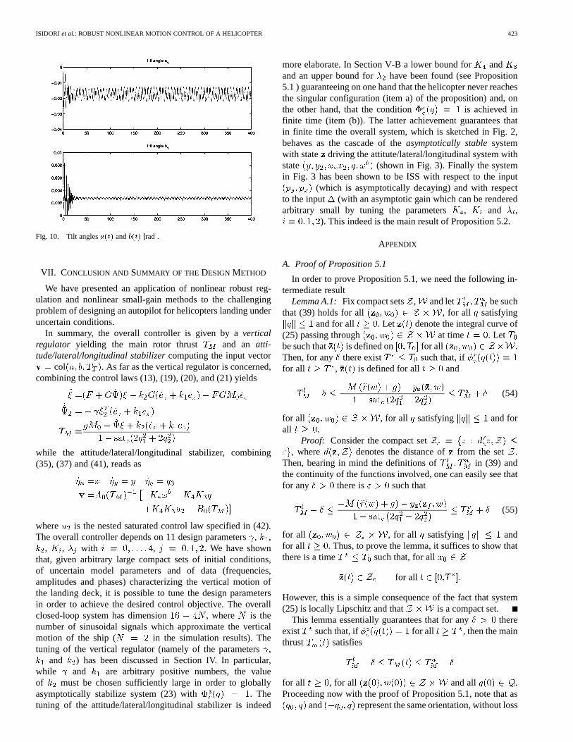
attitude does not converge to , as a result of the model un-certainties. As expected, while the attitude dynamics convergerapidly to the steady state (in about 40 s), the lateral and hori-zontal displacements are brought to zero in a slower time scale(see Fig. 8). The separation of the time scale into a faster anda slower dynamics is a common feature of control laws basedon a combination of high-gain and low-amplitude control, as inour case. Finally, Figs. 9 and 10 show the four control variables
, and , respectively. It is easy to see that the controllersucceeds in tracking the unknown reference and in stabilizingthe vehicle configuration, despite the large uncertainties on theplant model.
ISIDORI et al.: ROBUST NONLINEAR MOTION CONTROL OF A HELICOPTER 423
Fig. 10. Tilt anglesa(t) andb(t) [rad].
VII. CONCLUSION AND SUMMARY OF THE DESIGNMETHOD
We have presented an application of nonlinear robust reg-ulation and nonlinear small-gain methods to the challengingproblem of designing an autopilot for helicopters landing underuncertain conditions.
In summary, the overall controller is given by averticalregulator yielding the main rotor thrust and an atti-tude/lateral/longitudinal stabilizercomputing the input vector
col . As far as the vertical regulator is concerned,combining the control laws (13), (19), (20), and (21) yields
while the attitude/lateral/longitudinal stabilizer, combining(35), (37) and (41), reads as
where is the nested saturated control law specified in (42).The overall controller depends on 11 design parameters, ,
, , with , . We have shownthat, given arbitrary large compact sets of initial conditions,of uncertain model parameters and of data (frequencies,amplitudes and phases) characterizing the vertical motion ofthe landing deck, it is possible to tune the design parametersin order to achieve the desired control objective. The overallclosed-loop system has dimension , where is thenumber of sinusoidal signals which approximate the verticalmotion of the ship ( in the simulation results). Thetuning of the vertical regulator (namely of the parameters,
and ) has been discussed in Section IV. In particular,while and are arbitrary positive numbers, the valueof must be chosen sufficiently large in order to globallyasymptotically stabilize system (23) with . Thetuning of the attitude/lateral/longitudinal stabilizer is indeed
more elaborate. In Section V-B a lower bound for andand an upper bound for have been found (see Proposition5.1 ) guaranteeing on one hand that the helicopter never reachesthe singular configuration (item a) of the proposition) and, onthe other hand, that the condition is achieved infinite time (item (b)). The latter achievement guarantees thatin finite time the overall system, which is sketched in Fig. 2,behaves as the cascade of theasymptotically stablesystemwith state driving the attitute/lateral/longitudinal system withstate (shown in Fig. 3). Finally the systemin Fig. 3 has been shown to be ISS with respect to the input
(which is asymptotically decaying) and with respectto the input (with an asymptotic gain which can be renderedarbitrary small by tuning the parameters , and ,
). This indeed is the main result of Proposition 5.2.
APPENDIX
A. Proof of Proposition 5.1
In order to prove Proposition 5.1, we need the following in-termediate result
Lemma A.1:Fix compact sets , and let be suchthat (39) holds for all , for all satisfying
and for all . Let denote the integral curve of(25) passing through at time . Letbe such that is defined on for all .Then, for any there exist such that, iffor all , is defined for all and
(54)
for all , for all satisfying and forall .
Proof: Consider the compact set, where denotes the distance of from the set .
Then, bearing in mind the definitions of in (39) andthe continuity of the functions involved, one can easily see thatfor any there is such that
(55)
for all , for all satisfying andfor all . Thus, to prove the lemma, it suffices to show thatthere is a time such that, for all
for all
However, this is a simple consequence of the fact that system(25) is locally Lipschitz and that is a compact set.
This lemma essentially guarantees that for any thereexist such that, if for all , then the mainthrust satisfies
for all , for all and all .Proceeding now with the proof of Proposition 5.1, note that as
and represent the same orientation, without loss

424 IEEE TRANSACTIONS ON AUTOMATIC CONTROL, VOL. 48, NO. 3, MARCH 2003
of generality we can always assume if .Since is contained in the open ball of radius aroundthe origin in , it turns out that . Change coordinatesas
and consider the following Lyapunov function candidate:
(56)
defined on the set . Let be such that
Without loss of generality, assume , and define
Pick , , and, using lemma 1.1, choosein such a way that, if for all , then
for all . Let be a positive number such that
(57)
for all and . The existence of satisfying(57) is guaranteed by the fact that is a polyno-mial function of , and the initial conditions range on a com-pact set. Fix once and for all , and choose insuch a way that
Let and consider the compactsets , and where with ,, we denote
It is not difficult to see that
Furthermore, if
Let us compute the derivative of along trajectories of(40). The first term of (56) yields the following expression:
while the second reads as
Rearranging terms, we obtain
(58)
Let , be such that . Sinceand , the derivative of along solutions of (40) satisfies
for all . What follows is an extension ofthe results in [16] and [17]. Consider the compact set
, and note that on this set
(59)
To see that this is indeed the case, it suffices to notice that, onthe set
and
and, thus, (59) holds true if
(60)
which is always satisfied. We prove now that (59) holds every-where on . To this end, observe that, by continuity,inequality (59) continues to hold on an open supersetof
. Note that is com-pact and let

ISIDORI et al.: ROBUST NONLINEAR MOTION CONTROL OF A HELICOPTER 425
Needless to say, . Keeping in mind that ,we get
(61)
for all . It is easy to prove that thereexists a choice of and for which the inequality
(62)
holds true for all . In fact (62) holds onif
where which can be satisfied choosing
and
where and
The previous choices for and ensures that
for all . Moreover, using (60), it is easy tosee that
from which we conclude that (59) holds for all and,hence, everywhere on . This result shows that everytrajectory originated within is such thatthe corresponding trajectory is confined inside thepositively invariant set , and this proves claim a) of thelemma. To prove claim b), observe that by definition of, wehave and that also is positivelyinvariant. Since on , the result follows.
REFERENCES
[1] S. Devasia, “Output tracking with nonhyperbolic and near nonhyper-bolic internal dynamics: Helicopter hover control,”AIAA J. Guid., Con-trol, Dyna., vol. 20, no. 3, pp. 573–580, 1997.
[2] T. Koo and Sastry, “Output tracking control design of a helicopter modelbased on approximate linearization,” in 37th IEEE Conf. Decision Con-trol, Tampa, FL, 1998.
[3] S. Lane and R. Stengel, “Flight control design using nonlinear inversedynamics,”Automatica, vol. 24, no. 4, pp. 471–484, 1988.
[4] G. Meyer and L. Cicolani, “Application of nonlinear systems inverses toautomatic flight control design: System concepts and flight evaluations,”AGARDograph AG-251 Theory Appl. Optimal Control Aerosp. Syst., pp.10-1–10-29, 1980.
[5] J. Prasad, M. M., and D. Schrage, “Control of a twin lift helicoptersystem using nonlinear state feedback,”J. Amer. Helicopter Soc., vol.36, no. 4, pp. 57–65.
[6] O. Shakernia, Y. Ma, T. Koo, and S. Sastry, “Landing an unmanned airvehicle: vision based motion estimation and nonlinear control,”Asian J.Control, vol. 1, no. 3, pp. 128–144, 1999.
[7] H. Sira-Ramirez, R. Castro-Linares, and E. Liceaga-Castro, “A liou-villan system approach for the trajectory planning-based control of he-licopter models,”Int. J. Robust Nonlinear Control, vol. 10, no. 4, pp.301–320, 2000.
[8] S. Snell, D. Enns, and W. Garrard, “Nonlinear inversion flight controlfor a supermaneuverable aircraft,”AIAA J. Guid., Control, Dyna., vol.15, no. 4, pp. 976–984, 1992.
[9] L. Marconi, A. Isidori, and A. Serrani, “Autonomous vertical landing ona oscillating platform: an internal-model based approach,”Automatica,vol. 38, no. 1, pp. 21–32, 2001.
[10] A. Isidori, L. Marconi, and A. Serrani, “Computation of the zero-errormanifold for a problem of smooth vertical landing of a helicopter,” in6th Eur. Control Conf., Porto, Portugal, 2001.
[11] A. Isidori and C. I. Byrnes, “Output regulation of nonlinear systems,”IEEE Trans. Automat. Contr., vol. 35, pp. 131–140, Feb. 1990.
[12] A. Serrani, A. Isidori, and L. Marconi, “Semiglobal nonlinear outputregulation with adaptive internal model,”IEEE Trans. Automat. Contr.,vol. 46, pp. 1178–1194, Aug. 2001.
[13] L. Marconi and A. Isidori, “Robust global stabilization of a class of un-certain feedforward nonlinear systems,”Syst. Control Lett., vol. 41, pp.281–290, 2000.
[14] A. Isidori, L. Marconi, and A. Serrani, “Autonomous landing of un-manned helicopters,” Dipartimento di Elettronica, Informatica e Sis-temistica, Univ. degli Studi di Bologna, Bologna, Italy, 2001.
[15] A. Teel, “A nonlinear small gain theorem for the analysis of controlsystems with saturations,”IEEE Trans. Automat. Contr., vol. 41, pp.1256–1270, Sept. 1996.
[16] A. Bacciotti, “Linear fThe local and potentially global stabilization ofcascade systems,” in 2nd IFAC Symp. Nonlinear Control Systems De-sign, Bordeaux, France, June 1992.
[17] A. Teel and L. Praly, “Tools for semiglobal stabilization by partial andoutput feedback,”SIAM J. Control Optim., vol. 33, no. 5, pp. 1443–1488,Sept. 1995.
Alberto Isidori (M’80–SM’85–F’87) was born in Rapallo, Italy, in 1942. Hegraduated in electrical engineering from the University of Rome, Rome, Italy,in 1965.
Since 1975, he has been Professor of Automatic Control at the University ofRome. Since 1989, he has also been affiliated with the Department of SystemsScience and Mathematics, Washington University, St. Louis, MO. He hasheld visiting positions at various academic/research institutions, including theUniversity of Illinois at Urbana-Champaign, the University of California atBerkeley, the ETH in Zurich, Switzerland, and the NASA-Langley ResearchCenter, Hampton, VA. His research interests are primarily focused on math-ematical control theory and control engineering. He is the author of severalbooks, includingNonlinear Control Systems(New York: Springer Verlag,1985) and Nonlinear Control Systems II (New York: Springer Verlag, 1999).He is the author of more than 80 articles in archival journals, 16 book chapters,and more than 100 papers in referred conference proceedings, for a large parton the subject of nonlinear feedback design. He is also editor/coeditor of 16volumes of conference proceedings.
Dr. Isidori received the George S. Axelby Outstanding Paper Award in 1981and 1990. He also received theAutomaticaBest Paper Award in 1991. In 1996,he received from IFAC the “Giorgio Quazza Medal” for “pioneering and funda-mental contributions to the theory of nonlinear feedback control.” In 2000, hewas awarded the first “Ktesibios Award” from the Mediterranean Control Asso-ciation. In 2001, he received the “Bode Lecture Prize” from the IEEE ControlSystems Society, and from 1993 to 1996, he served on the Council of IFAC.From 1995 to 1997, he was President of the European Community Control Asso-ciation, and he is listed in the Highly-Cited database (http://isihighlycited.com)among the top most-cited authors in engineering.

426 IEEE TRANSACTIONS ON AUTOMATIC CONTROL, VOL. 48, NO. 3, MARCH 2003
Lorenzo Marconi (S’98–M’99) was born in Rimini, Italy, in 1970. He gradu-ated in electrical engineering and received the Ph.D. degree from the Universityof Bologna, Bologna, Italy, in 1995 and 1998, respectively.
Since 1995, he has been with the Department of Electronics, Computer Sci-ence, and Systems at the University of Bologna. Since 1999, he has been aResearcher in automatic control in the same department. From August to De-cember 1997, and from November to December 1998, he held visiting positionsat the Department of Systems Science and Mathematics, Washington University,St. Louis, MO. His current research interests include nonlinear control, outputregulation, geometric approach, and fault detection.
Andrea Serrani (S’95–M’00) received theLaureadegree (B.Eng.)cum laudein electrical engineering and theDottorato di Ricerca(Ph.D.) in artificial intelli-gence systems from the University of Ancona, Ancona, Italy, and the D.Sci. de-gree in systems science and mathematics from Washington University, St. Louis,MO, in 1993, 1997, and 2000, respectively.
From 1994 to 1999, he was a Fulbright Fellow at the Department of SystemsScience and Mathematics,Washington University. From 2000 to 2002, he held aResearch Associate position at the Department of Electronics and Automationat the University of Ancona. Since 2002, he has been an Assistant Professorwith the Department of Electrical Engineering at The Ohio State University,Columbus. His research interests lie in the field of control and systems theory,with emphasis on nonlinear control, nonlinear dynamical systems, and controlof autonomous vehicles.
Related Documents