Noname manuscript No. (will be inserted by the editor) Robust Hand Image Processing for Biometric Application Jugurta Montalv˜ ao 1 , Lucas Molina 1 , Jˆ anio Canuto 1 Universidade Federal de Sergipe (UFS), S˜ao Crist´ov˜ao, CEP. 49100-000. Received: date / Revised version: date Abstract A new approach for both hand image seg- mentation and feature extraction is described. The main advantage of this approach, namely its robustness to low quality images, is illustrated through verification exper- iments with two public databases: one with scanned im- ages from 50 subjects, and another one with low qual- ity images acquired from 23 subjects, from a conven- tional webcam. In both cases, features are successfully extracted and good performances are obtained, in spite of image quality. Moreover, the main drawbacks of fea- ture extraction in conventional algorithms are highlighted. 1 Introduction Hand shape recognition for individual identification/ ver- ification is now a well known biometric modality [1–3]. It is roughly based upon the hypothesis that individuals have different hand geometries (e.g. finger lengths, finger widths, palm area). Another important hand based biometric approach takes into account palmprints [4,5] instead of contours and/or finger/palm dimensions. Although the fusion of both approaches seems to be a natural trend for hand biometrics, this paper is only concerned with shape based issues. In spite of the relatively low performance of this kind of biometric scheme, mainly if compared to typi- cal fingerprint or iris based schemes, hand geometry is attractive because of its unobtrusiveness, low-cost and low data storage requirement [6]. Nevertheless, unlike fingerprints, for instance, hand geometry is expected to be more prone to deformations, mainly due to free fin- ger rotations. Consequently, early attempts at individ- ual authentication through hand geometry were mostly based on digital images from hands placed on flat sur- faces with fixed pegs carefully placed in order to con- strain the hands into a standard position, before hand picture is taken and digitalized [1]. It is also known [2] that, though pegs indeed facili- tate image segmentation and feature extraction, it does not totally avoid finger translation/rotation and, unless some kind of image normalization is applied prior to hand-to-hand geometry comparisons, performances can be strongly degraded due to even small mismatchings be- tween parts of such images. Indeed, assuming that mis- matchings between images to be compared are a kind of measurement noise, it has been observed that, in some cases, this noise can be much greater than differences be- tween hand geometries from individuals (i.e. useful sig- nal), which are often minute [6]. Moreover, pegs or other positioning devices may de- form hand shape if they push the hand skin during data acquisition. For instance, in [1], finger widths just beside pegs are avoided during feature extraction. Most recent approaches that have appeared in lit- erature claim that they allow “free” hand positioning during acquisition. However, according to what we can infer from database samples presented in [7], [8] and [3], for instance, subjects are somehow induced to place their hands according to a preestablished orientation for the whole hand, into a limited area, from which they are fi- nally free to rotate their fingers, given that fingers do not touch each other. Indeed, this is explicitly mentioned in [2]. A few state-of-the-art works also propose strategies for “contact-free” hand feature extraction, such as in [9, 10]. Though these approaches are more computationally demanding — because hands are free to rove around a 3-D limited space, instead of the usual 2-D flat surfaces — they represent a new paradigm in terms of user accep- tance. Unfortunately, they face some segmentation prob- lems that are beyond the scope of this paper. Therefore, in this paper, though some 3-D segmentation problems are briefly mentioned in Section 2, we limit our focus to 2-D hand representation, acquired from flat surfaces. In spite of the diversity and creativeness of new ap- proaches to process “freely” placed hands, on flat sur- faces, there is, at least, a common point among most of

Welcome message from author
This document is posted to help you gain knowledge. Please leave a comment to let me know what you think about it! Share it to your friends and learn new things together.
Transcript
Noname manuscript No.(will be inserted by the editor)
Robust Hand Image Processing for Biometric Application
Jugurta Montalvao1, Lucas Molina1, Janio Canuto1
Universidade Federal de Sergipe (UFS), Sao Cristovao, CEP. 49100-000.
Received: date / Revised version: date
Abstract A new approach for both hand image seg-mentation and feature extraction is described. The mainadvantage of this approach, namely its robustness to lowquality images, is illustrated through verification exper-iments with two public databases: one with scanned im-ages from 50 subjects, and another one with low qual-ity images acquired from 23 subjects, from a conven-tional webcam. In both cases, features are successfullyextracted and good performances are obtained, in spiteof image quality. Moreover, the main drawbacks of fea-ture extraction in conventional algorithms are highlighted.
1 Introduction
Hand shape recognition for individual identification/ ver-ification is now a well known biometric modality [1–3].It is roughly based upon the hypothesis that individualshave different hand geometries (e.g. finger lengths, fingerwidths, palm area).
Another important hand based biometric approachtakes into account palmprints [4,5] instead of contoursand/or finger/palm dimensions. Although the fusion ofboth approaches seems to be a natural trend for handbiometrics, this paper is only concerned with shape basedissues.
In spite of the relatively low performance of thiskind of biometric scheme, mainly if compared to typi-cal fingerprint or iris based schemes, hand geometry isattractive because of its unobtrusiveness, low-cost andlow data storage requirement [6]. Nevertheless, unlikefingerprints, for instance, hand geometry is expected tobe more prone to deformations, mainly due to free fin-ger rotations. Consequently, early attempts at individ-ual authentication through hand geometry were mostlybased on digital images from hands placed on flat sur-faces with fixed pegs carefully placed in order to con-strain the hands into a standard position, before handpicture is taken and digitalized [1].
It is also known [2] that, though pegs indeed facili-tate image segmentation and feature extraction, it doesnot totally avoid finger translation/rotation and, unlesssome kind of image normalization is applied prior tohand-to-hand geometry comparisons, performances canbe strongly degraded due to even small mismatchings be-tween parts of such images. Indeed, assuming that mis-matchings between images to be compared are a kind ofmeasurement noise, it has been observed that, in somecases, this noise can be much greater than differences be-tween hand geometries from individuals (i.e. useful sig-nal), which are often minute [6].
Moreover, pegs or other positioning devices may de-form hand shape if they push the hand skin during dataacquisition. For instance, in [1], finger widths just besidepegs are avoided during feature extraction.
Most recent approaches that have appeared in lit-erature claim that they allow “free” hand positioningduring acquisition. However, according to what we caninfer from database samples presented in [7], [8] and [3],for instance, subjects are somehow induced to place theirhands according to a preestablished orientation for thewhole hand, into a limited area, from which they are fi-nally free to rotate their fingers, given that fingers do nottouch each other. Indeed, this is explicitly mentioned in[2].
A few state-of-the-art works also propose strategiesfor “contact-free” hand feature extraction, such as in [9,10]. Though these approaches are more computationallydemanding — because hands are free to rove around a3-D limited space, instead of the usual 2-D flat surfaces— they represent a new paradigm in terms of user accep-tance. Unfortunately, they face some segmentation prob-lems that are beyond the scope of this paper. Therefore,in this paper, though some 3-D segmentation problemsare briefly mentioned in Section 2, we limit our focus to2-D hand representation, acquired from flat surfaces.
In spite of the diversity and creativeness of new ap-proaches to process “freely” placed hands, on flat sur-faces, there is, at least, a common point among most of
2 Jugurta Montalvao et al.
them: they depend upon boundary-following algorithms,even though relatively little attention is paid to thisvery first step to be done. Consequently, motivated bythe lack of robustness of boundary-tracking algorithms,mainly when applied to noisy images of hands with ringsor other jewelry, we propose here a new method whereno explicit contour tracing algorithms are applied.
In our approach — somehow inspired by the En-semble Histogram Interval (EIH) approach [11] mainlyapplied to speech signals, whose main advantage is itsrobustness against noise —, hand images are scannedcolumn by column (or row by row, alternatively), andfingers are detected by signal frequency analysis.
Thus, the main matter of this work is robustness ofhand image processing, which is discussed in Section 2,prior to the description of the proposed method, in Sec-tions 3 and 4. In Section 5, some details concerning data-bases used in this work are given. In Section 6, experi-mental results are presented and, finally, we discuss themain issues from the new proposal in Section 7.
2 Robustness Issues
Feature extraction approaches from hand images in [1],[2], [12], [6], [13], [8], [14] and [15], for instance, dependupon common preprocessing steps, namely: foregroundsegmentation, boundary detection. Moreover, except for[1] and [15], they also depend on contour tracking al-gorithms. Additionally, after contour tracking is done,corresponding finger and palm contours must be prop-erly segmented.
In most published works, where hand images are scannedwith conventional desktop scanners, or pictures are takenunder controlled illumination, foreground segmentationis not an important matter. For instance, in [6], bothsimple clustering and more sophisticated watershed transform-based segmentation were compared through their data-base, providing equivalent results. Similarly, in [3], afterexperiments with three clustering algorithms for gray-level threshold search, the authors finally concluded thatsmall variations in the threshold choice do not relevantlyaffect their final results. Thus, for their database, a rangefrom 65 to 100 (in 256 gray levels) was considered as thethreshold choice.
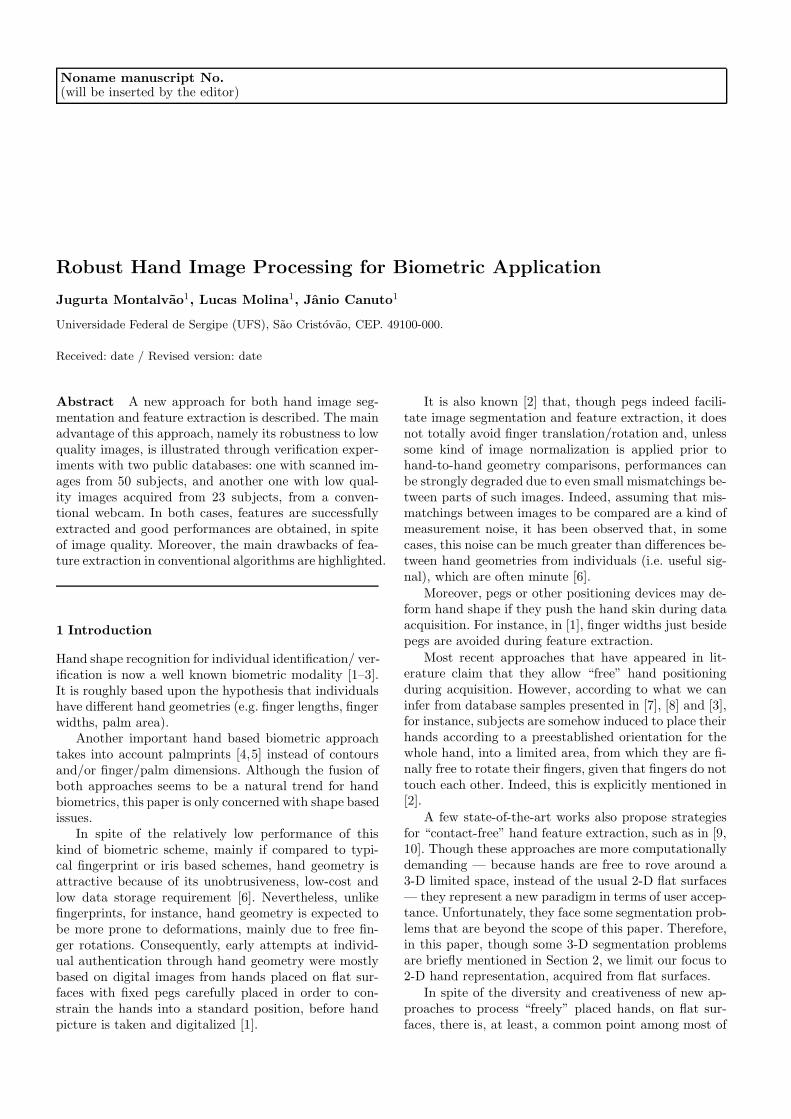
On the other hand, boundary detection and contourtracking seem to be less straightforward matters. Surely,even a simple contour tracking algorithm, whenever it isproperly initialized, may do the job correctly. Figure 1illustrates such a case.
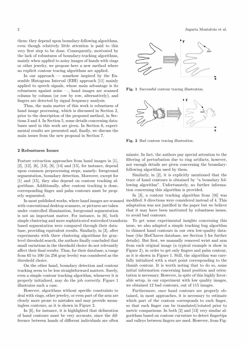
However, algorithms without specific constraints todeal with rings, other jewelry, or even part of the arm areclearly more prone to mistakes and may provide mean-ingless contours, as it is shown in Figure 2.
In [6], for instance, it is highlighted that delineationof hand contours must be very accurate, since the dif-ference between hands of different individuals are often
Fig. 1 Successful contour tracing illustration.
Fig. 2 Bad contour tracing illustration.
minute. In fact, the authors pay special attention to thefiltering of perturbation due to ring artifacts, however,not enough details are given concerning the boundary-following algorithm used by them.
Similarly, in [2], it is explicitly mentioned that thetrace of hand contours is obtained by “a boundary fol-lowing algorithm”. Unfortunately, no further informa-tion concerning this algorithm is provided.
In [3], a contour tracking algorithm from [16] wasmodified: 8 directions were considered instead of 4. Thisadaptation was not justified in the paper but we believethat it may have been motivated by robustness issues,to avoid bad contours.
To get some experimental insights concerning thisissue, we also adapted a simple tracking bug algorithmto thinned hand contours in our own low-quality data-base (the BioChaves database, see Section 5 for furtherdetails). But first, we manually removed wrist and armfrom each original image (a typical example is show inFigure 2), in order to get only fingers and palm contour,as it is shown in Figure 1. Still, the algorithm was care-fully initialized with a start point corresponding to thethumb contour. It is worth noting that to do so, someinitial information concerning hand position and orien-tation is necessary. However, in spite of this highly favor-able setup, in our experiment with low quality images,we obtained 12 bad contours, out of 115 images.
Furthermore, once hand contours are properly ob-tained, in most approaches, it is necessary to estimatewhich part of the contour corresponds to each finger,so that each finger can be translated/rotated prior tometric comparisons. In both [2] and [13] very similar al-gorithms based on contour curvature to detect fingertipsand valleys between fingers are used. However, from Fig-
Robust Hand Image Processing for Biometric Application 3
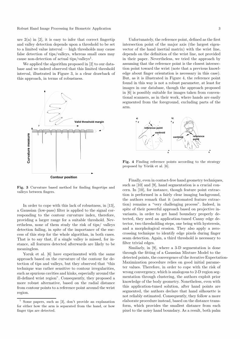
ure 2(a) in [2], it is easy to infer that correct fingertipand valley detection depends upon a threshold to be setto a limited value interval — high thresholds may causefalse detection of tips/valleys, whereas small ones maycause non-detection of actual tips/valleys1.
We applied the algorithm proposed in [2] to our data-base and we indeed observed that this limited thresholdinterval, illustrated in Figure 3, is a clear drawback ofthis approach, in terms of robustness.
Fig. 3 Curvature based method for finding fingertips andvalleys between fingers.
In order to cope with this lack of robustness, in [13],a Gaussian (low-pass) filter is applied to the signal cor-responding to the contour curvature index, therefore,providing a larger range for a suitable threshold. Nev-ertheless, none of them study the risk of tips/ valleysdetection failing, in spite of the importance of the suc-cess of this step for the whole algorithm, in both cases.That is to say that, if a single valley is missed, for in-stance, all features detected afterwards are likely to bemeaningless.
Yoruk et al. [6] have experimented with the sameapproach based on the curvature of the contour for de-tection of tips and valleys, but they observed that “thistechnique was rather sensitive to contour irregularities,such as spurious cavities and kinks, especially around theill-defined wrist region”. Consequently, they proposed amore robust alternative, based on the radial distancefrom contour points to a reference point around the wristregion.
1 Some papers, such as [3], don’t provide an explanationfor either how the arm is separated from the hand, or howfinger tips are detected.
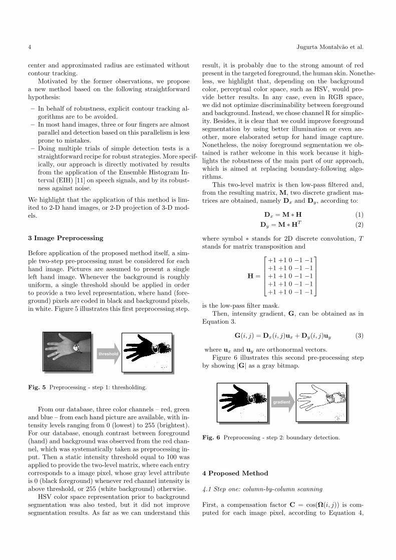
Unfortunately, the reference point, defined as the firstintersection point of the major axis (the largest eigen-vector of the hand inertial matrix) with the wrist line,depends on the definition of the wrist line, not providedin their paper. Nevertheless, we tried the approach byassuming that the reference point is the closest intersec-tion point toward the wrist (note that a previous knowl-edge about finger orientation is necessary in this case).But, as it is illustrated in Figure 4, the reference pointfound in this way is not a robust parameter, at least forimages in our database, though the approach proposedin [6] is possibly suitable for images taken from conven-tional scanners, as in their work, where hands are easilysegmented from the foreground, excluding parts of thearm.
Fig. 4 Finding reference points according to the strategyproposed by Yoruk et al. [6].
Finally, even in contact-free hand geometry techniques,such as [10] and [9], hand segmentation is a crucial con-cern. In [10], for instance, though feature point extrac-tion is performed in a fairly clear imaging background,the authors remark that it (automated feature extrac-tion) remains a “very challenging process”. Indeed, inspite of their powerful approach based on projective in-variants, in order to get hand boundary properly de-tected, they need an application-tuned Canny edge de-tector, two thresholding steps, one being with hysteresis,and a morphological erosion. They also apply a zero-crossing technique to identify edge pixels during fingerseam detection. Again, a third threshold is necessary tofilter trivial edges.
Similarly, in [9], where a 3-D segmentation is donethrough the fitting of a Gaussian Mixture Model to thedetected points, the convergence of the iterative Expectation-Maximization procedure relies on good initial parame-ter values. Therefore, in order to cope with the risk ofwrong convergency, which is analogous to 2-D region seg-mentation through clustering, the authors exploit priorknowledge of the body geometry. Nonetheless, even withthis application-tuned solution, after hand points aresegmented, the authors declare that hand silhouette isnot reliably estimated. Consequently, they follow a moreelaborate procedure instead, based on the distance trans-form, which provides the smallest distance from eachpixel to the noisy hand boundary. As a result, both palm
4 Jugurta Montalvao et al.
center and approximated radius are estimated withoutcontour tracking.
Motivated by the former observations, we proposea new method based on the following straightforwardhypothesis:
– In behalf of robustness, explicit contour tracking al-gorithms are to be avoided.
– In most hand images, three or four fingers are almostparallel and detection based on this parallelism is lessprone to mistakes.
– Doing multiple trials of simple detection tests is astraightforward recipe for robust strategies. More specif-ically, our approach is directly motivated by resultsfrom the application of the Ensemble Histogram In-terval (EIH) [11] on speech signals, and by its robust-ness against noise.
We highlight that the application of this method is lim-ited to 2-D hand images, or 2-D projection of 3-D mod-els.
3 Image Preprocessing
Before application of the proposed method itself, a sim-ple two-step pre-processing must be considered for eachhand image. Pictures are assumed to present a singleleft hand image. Whenever the background is roughlyuniform, a single threshold should be applied in orderto provide a two level representation, where hand (fore-ground) pixels are coded in black and background pixels,in white. Figure 5 illustrates this first preprocessing step.
Fig. 5 Preprocessing - step 1: thresholding.
From our database, three color channels – red, greenand blue – from each hand picture are available, with in-tensity levels ranging from 0 (lowest) to 255 (brightest).For our database, enough contrast between foreground(hand) and background was observed from the red chan-nel, which was systematically taken as preprocessing in-put. Then a static intensity threshold equal to 100 wasapplied to provide the two-level matrix, where each entrycorresponds to a image pixel, whose gray level attributeis 0 (black foreground) whenever red channel intensity isabove threshold, or 255 (white background) otherwise.
HSV color space representation prior to backgroundsegmentation was also tested, but it did not improvesegmentation results. As far as we can understand this
result, it is probably due to the strong amount of redpresent in the targeted foreground, the human skin. Nonethe-less, we highlight that, depending on the backgroundcolor, perceptual color space, such as HSV, would pro-vide better results. In any case, even in RGB space,we did not optimize discriminability between foregroundand background. Instead, we chose channel R for simplic-ity. Besides, it is clear that we could improve foregroundsegmentation by using better illumination or even an-other, more elaborated setup for hand image capture.Nonetheless, the noisy foreground segmentation we ob-tained is rather welcome in this work because it high-lights the robustness of the main part of our approach,which is aimed at replacing boundary-following algo-rithms.
This two-level matrix is then low-pass filtered and,from the resulting matrix, M, two discrete gradient ma-trices are obtained, namely Dx and Dy, according to:
Dx = M ∗ H (1)
Dy = M ∗ HT (2)
where symbol ∗ stands for 2D discrete convolution, Tstands for matrix transposition and
H =
+1 +1 0 −1 −1+1 +1 0 −1 −1+1 +1 0 −1 −1+1 +1 0 −1 −1+1 +1 0 −1 −1
is the low-pass filter mask.Then, intensity gradient, G, can be obtained as in
Equation 3.
G(i, j) = Dx(i, j)ux + Dy(i, j)uy (3)
where ux and uy are orthonormal vectors.Figure 6 illustrates this second pre-processing step
by showing |G| as a gray bitmap.
Fig. 6 Preprocessing - step 2: boundary detection.
4 Proposed Method
4.1 Step one: column-by-column scanning
First, a compensation factor C = cos(Ω(i, j)) is com-puted for each image pixel, according to Equation 4,
Robust Hand Image Processing for Biometric Application 5
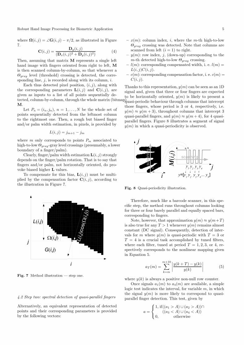
where Ω(i, j) = ∠G(i, j) − π/2, as illustrated in Figure7.
C(i, j) =Dy(i, j)
(Dx(i, j)2 + Dy(i, j)2)(4)
Then, assuming that matrix M represents a single lefthand image with fingers oriented from right to left, M
is then scanned column-by-column, so that whenever aΘgray level (threshold) crossing is detected, the corre-sponding line, j, is recorded along with its column, i.
Each thus detected pixel position, (i, j), along withthe corresponding parameters L(i, j) and C(i, j), aregiven as inputs to a list of all points sequentially de-tected, column-by-column, through the whole matrix (bitmap)M.
Let Pn = (in, jn), n = 1, . . . , N be the whole set ofpoints sequentially detected from the leftmost columnto the rightmost one. Then, a rough but biased fingerand/or palm width estimation, in pixels, is provided by
L(i, j) = jm+1 − jm
where m only corresponds to points Pm associated tohigh-to-low Θgray-gray level crossings (presumably, a lowerboundary of a finger/palm).
Clearly, finger/palm width estimation L(i, j) stronglydepends on the finger/palm rotation. That is to say thatfingers and/or palm, not horizontally oriented, do pro-voke biased higher L values.
To compensate for this bias, L(i, j) must be multi-plied by the compensation factor C(i, j), according tothe illustration in Figure 7.
Fig. 7 Method illustration — step one.
4.2 Step two: spectral detection of quasi-parallel fingers
Alternatively, an equivalent representation of detectedpoints and their corresponding parameters is providedby the following vectors:
– x(m): column index, i, where the m-th high-to-lowΘgray crossing was detected. Note that columns arescanned from left (i = 1) to right.
– y(m): row index, j, (down-up) corresponding to them-th detected high-to-low Θgray crossing.
– l(m): corresponding compensated width, i. e. l(m) =L(i, j)C(i, j).
– c(m): corresponding compensation factor, i. e. c(m) =C(i, j).
Thanks to this representation, y(m) can be seen as an 1Dsignal and, given that three or four fingers are expectedto be horizontally oriented, y(m) is likely to present aquasi-periodic behaviour through columns that interceptthose fingers, whose period is 3 or 4, respectively, i.e.y(m) ≈ y(m + 3), throughout columns that intercept 3quasi-parallel fingers, and y(m) ≈ y(m + 4), for 4 quasi-parallel fingers. Figure 8 illustrates a segment of signaly(m) in which a quasi-periodicity is observed.
Fig. 8 Quasi-periodicity illustration.
Therefore, much like a barcode scanner, in this spe-cific step, the method runs throughout columns lookingfor three or four barely parallel and equally spaced bars,corresponding to fingers.
Note, however, that approximation y(m) ≈ y(m+T )is also true for any T > 1 whenever y(m) remains almostconstant (DC signal). Consequently, detection of inter-vals for m where y(m) is quasi-periodic with T = 3 orT = 4 is a crucial task accomplished by tuned filters,where each filter, tuned at period T = 1, 2, 3, or 4, re-spectively corresponds to the nonlinear mapping givenin Equation 5.
aT (m) =
m+10∑
k=m
∣
∣
∣
∣
y(k + T ) − y(k)
y(k)
∣
∣
∣
∣
(5)
where y(k) is always a positive non-null row counter.Once signals a1(m) to a4(m) are available, a simple
logic test indicates the interval, for variable m, in whichthe signal y(m) is more likely to correspond to quasi-parallel finger detection. This test, given by
a =
1, if((a1 > A) ∪ (a2 > A))∩((a3 < A) ∪ (a4 < A))
0, otherwise
6 Jugurta Montalvao et al.
(where threshold A = 0.01 was set experimentally), looksfor quasi-periodicity of y(m), while it also avoids con-stant and quasi-constant signals.
It is worth noting that threshold A = 0.01 only de-pends on the noise level of the image, and we experi-mentally observed that 0.01 seems to be a suitable valueeven for low quality images, as in our database.
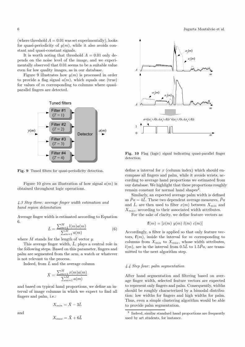
Figure 9 illustrates how y(m) is processed in orderto provide a flag signal a(m), which equals one (true)for values of m corresponding to columns where quasi-parallel fingers are detected.
Fig. 9 Tuned filters for quasi-periodicity detection.
Figure 10 gives an illustration of how signal a(m) isobtained throughout logic operations.
4.3 Step three: average finger width estimation and
hand region delimitation
Average finger width is estimated according to Equation6.
L =
∑M
m=1l(m)a(m)
∑M
m=1a(m)
(6)
where M stands for the length of vector y.This average finger width, L, plays a central role in
the following steps. Based on this parameter, fingers andpalm are segmented from the arm, a watch or whateveris not relevant to the process.
Indeed, from L and the average column
X =
∑M
m=1x(m)a(m)
∑M
m=1a(m)
and based on typical hand proportions, we define an in-terval of image columns in which we expect to find allfingers and palm, i.e.:
Xmin = X − 3L
andXmax = X + 6L
Fig. 10 Flag (logic) signal indicating quasi-parallel fingerdetection.
define a interval for x (column index) which should en-compass all fingers and palm, while it avoids wrists, ac-cording to average hand proportions we estimated fromour database. We highlight that these proportions roughlyremain constant for normal hand shapes2.
Similarly, an expected average palm width is definedas P a = 4L. These two dependent average measures, P aand L, are then used to filter x(m) between Xmin andXmax, according to their associated width attributes.
For the sake of clarity, we define feature vectors as:
f(m) = [x(m) y(m) l(m) c(m)]
Accordingly, a filter is applied so that only feature vec-tors, f(m), inside the interval for m corresponding tocolumns from Xmin to Xmax, whose width attributes,l(m), are in the interval from 0.5L to 1.5P a, are trans-mitted to the next algorithm step.
4.4 Step four: palm segmentation
After hand segmentation and filtering based on aver-age finger width, selected feature vectors are expectedto represent only fingers and palm. Consequently, widthsshould be roughly characterized by a bimodal distribu-tion: low widths for fingers and high widths for palm.Thus, even a simple clustering algorithm would be ableto provide palm segmentation.
2 Indeed, similar standard hand proportions are frequentlyused by art students, for instance.
Robust Hand Image Processing for Biometric Application 7
Nevertheless, for robustness concerns, we apply herea simple threshold based selection, i.e., feature vectorswhose width attributes are greater than 3L are seg-mented as palm features. Note that this threshold isadaptive, for it depends on L.
4.5 Step five: finger segmentation
Initially, feature vectors whose width attributes lie be-tween 0.5L and 1.5L are segmented as fingers.
The whole set of feature vectors thus segmented asfingers is to be properly clustered and labeled as thumb,index, middle, ring, or little finger. For this specific task,we use a simple but robust sequential clustering algo-rithm, which can be summarized as follows:
1. Initialize 9 clusters with null feature vectors.2. Through columns corresponding to segmented fin-
gers, from left to right, do:2.1 Compute the absolute difference between attribute
y(m), (row) from each feature vector, and the cor-responding feature from the last input in eachcluster.
2.2 If the minimum absolute difference is less thanL/2, then accept this feature vector as a new in-put to the corresponding cluster (closest one).
2.3 Otherwise, if there is still a cluster with only nullvectors, accept the new feature vector as the firstnon-null input to it (i.e., start a new non-null clus-ter). In case all clusters are already fulfilled withnon-null entries, then stop.
3. Sort all clusters according to their cardinality andtake the five biggest ones.
4. Sort these 5 biggest clusters according to the averagey attribute (centroid row, y)
5. From the highest to the lowest y, corresponding clus-ters are associated, respectively, to thumb (1), index(2), middle (3), ring (4), or little (5) finger.
Thus, from each hand picture, 6 sets of non-null fea-ture vectors are extracted, namely: F0, from palm, F1,F2, F3, F4 and F5 from thumb, index, middle, ring, andlittle finger, respectively.
Finally, in agreement with the study presented in [2],concerning the sub-segmentation of fingers into smallerparts to improve distinctiveness between individuals, setsFk, k = 1, . . . , 5, are split into subsets Fk,1, Fk,2, . . .,Fk,NP , where NP stands for the number of finger slices(subsets) to be considered.
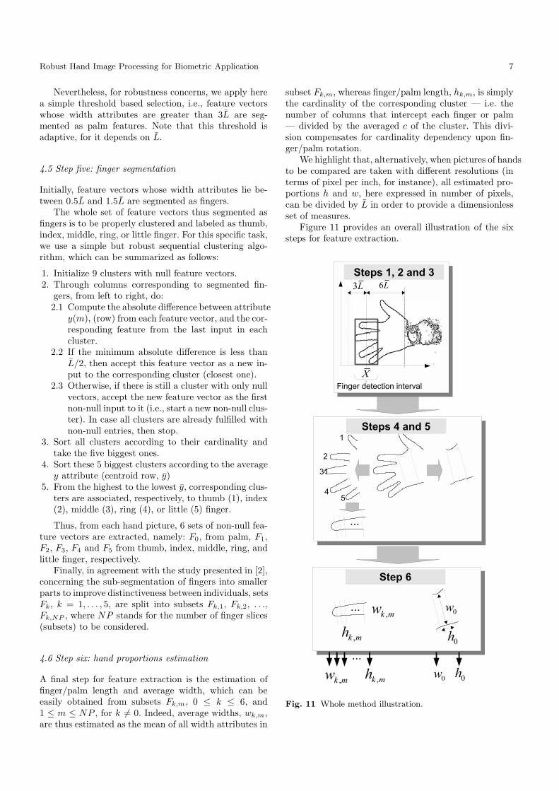
4.6 Step six: hand proportions estimation
A final step for feature extraction is the estimation offinger/palm length and average width, which can beeasily obtained from subsets Fk,m, 0 ≤ k ≤ 6, and1 ≤ m ≤ NP , for k 6= 0. Indeed, average widths, wk,m,are thus estimated as the mean of all width attributes in
subset Fk,m, whereas finger/palm length, hk,m, is simplythe cardinality of the corresponding cluster — i.e. thenumber of columns that intercept each finger or palm— divided by the averaged c of the cluster. This divi-sion compensates for cardinality dependency upon fin-ger/palm rotation.
We highlight that, alternatively, when pictures of handsto be compared are taken with different resolutions (interms of pixel per inch, for instance), all estimated pro-portions h and w, here expressed in number of pixels,can be divided by L in order to provide a dimensionlessset of measures.
Figure 11 provides an overall illustration of the sixsteps for feature extraction.
Fig. 11 Whole method illustration.
8 Jugurta Montalvao et al.
4.7 Hand proportions comparison
Let hu, wu represent hand features from the u-th picturein the database, whereas hv, wv, represent those from thev-th picture. A simple comparison between hand shapesis provided by the summation of absolute differences be-tween corresponding features, i.e., the Manhattan dis-tance between features [17].
5 Data Acquisition
Two databases were used in experiments with the pro-posed method:
a) the BioChaves hand database3 ,b) and the GPDS [3] database, downloaded from the
Internet in December 2006.
In the BioChaves database, hand pictures were takenwith a conventional low cost webcam, attached to a sup-port over a black background. Figure 12 illustrates thissetup, where we can observe that 6 white paper strips,over the black background, roughly orientate hand posi-tioning. That is to say that, in the BioChaves database,hands are not freely positioned, though no pegs wereused. Furthermore, images were acquired in low resolu-tion: 288 rows per 352 columns, and illumination pro-vided just by the fluorescent lamps already present inour laboratory.
Fig. 12 Image acquisition setup.
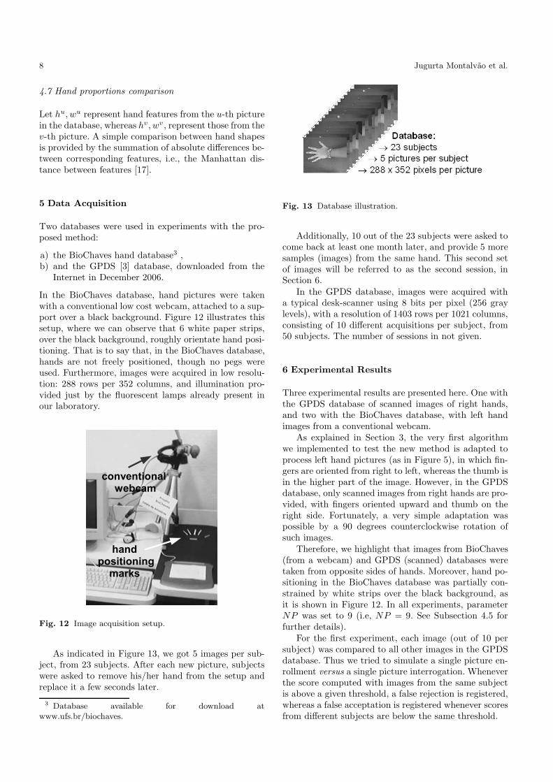
As indicated in Figure 13, we got 5 images per sub-ject, from 23 subjects. After each new picture, subjectswere asked to remove his/her hand from the setup andreplace it a few seconds later.
3 Database available for download atwww.ufs.br/biochaves.
Fig. 13 Database illustration.
Additionally, 10 out of the 23 subjects were asked tocome back at least one month later, and provide 5 moresamples (images) from the same hand. This second setof images will be referred to as the second session, inSection 6.
In the GPDS database, images were acquired witha typical desk-scanner using 8 bits per pixel (256 graylevels), with a resolution of 1403 rows per 1021 columns,consisting of 10 different acquisitions per subject, from50 subjects. The number of sessions in not given.
6 Experimental Results
Three experimental results are presented here. One withthe GPDS database of scanned images of right hands,and two with the BioChaves database, with left handimages from a conventional webcam.
As explained in Section 3, the very first algorithmwe implemented to test the new method is adapted toprocess left hand pictures (as in Figure 5), in which fin-gers are oriented from right to left, whereas the thumb isin the higher part of the image. However, in the GPDSdatabase, only scanned images from right hands are pro-vided, with fingers oriented upward and thumb on theright side. Fortunately, a very simple adaptation waspossible by a 90 degrees counterclockwise rotation ofsuch images.
Therefore, we highlight that images from BioChaves(from a webcam) and GPDS (scanned) databases weretaken from opposite sides of hands. Moreover, hand po-sitioning in the BioChaves database was partially con-strained by white strips over the black background, asit is shown in Figure 12. In all experiments, parameterNP was set to 9 (i.e, NP = 9. See Subsection 4.5 forfurther details).
For the first experiment, each image (out of 10 persubject) was compared to all other images in the GPDSdatabase. Thus we tried to simulate a single picture en-rollment versus a single picture interrogation. Wheneverthe score computed with images from the same subjectis above a given threshold, a false rejection is registered,whereas a false acceptation is registered whenever scoresfrom different subjects are below the same threshold.
Robust Hand Image Processing for Biometric Application 9
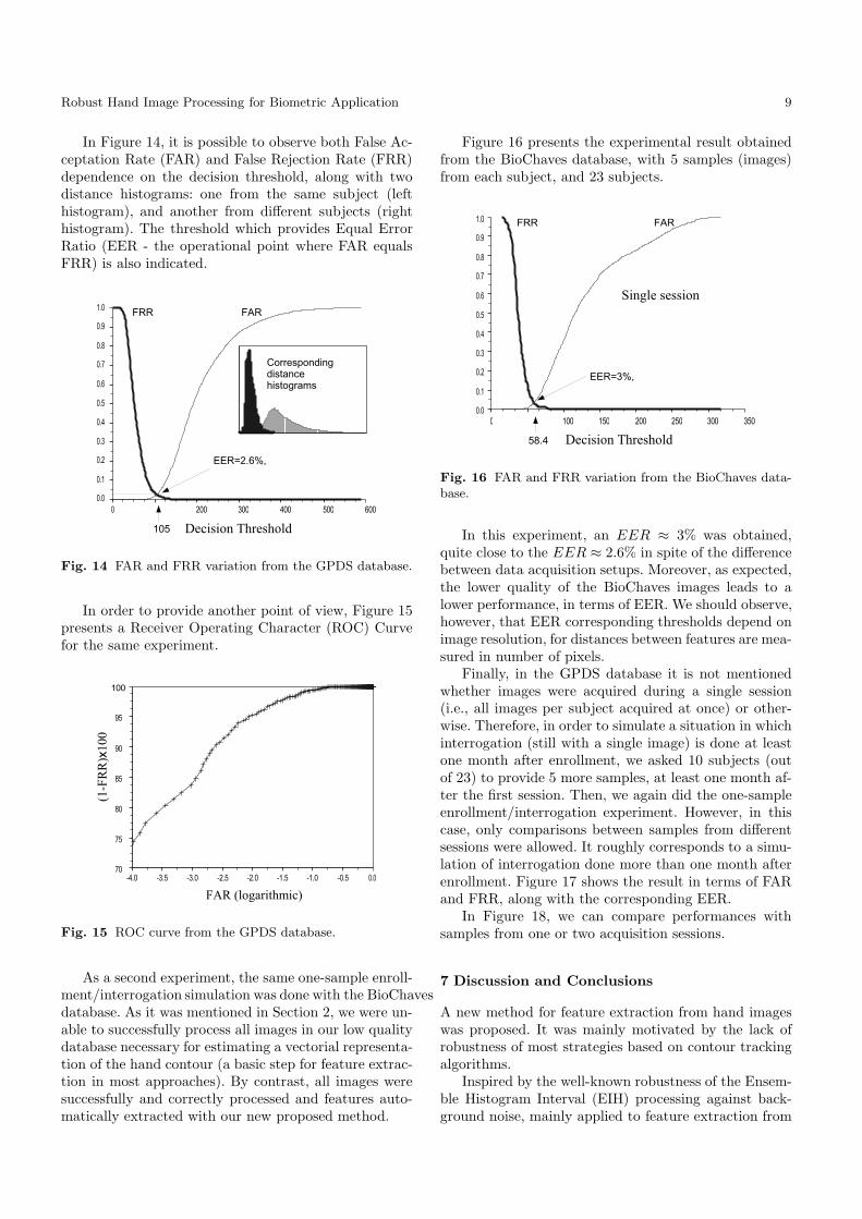
In Figure 14, it is possible to observe both False Ac-ceptation Rate (FAR) and False Rejection Rate (FRR)dependence on the decision threshold, along with twodistance histograms: one from the same subject (lefthistogram), and another from different subjects (righthistogram). The threshold which provides Equal ErrorRatio (EER - the operational point where FAR equalsFRR) is also indicated.
Fig. 14 FAR and FRR variation from the GPDS database.
In order to provide another point of view, Figure 15presents a Receiver Operating Character (ROC) Curvefor the same experiment.
Fig. 15 ROC curve from the GPDS database.
As a second experiment, the same one-sample enroll-ment/interrogation simulation was done with the BioChavesdatabase. As it was mentioned in Section 2, we were un-able to successfully process all images in our low qualitydatabase necessary for estimating a vectorial representa-tion of the hand contour (a basic step for feature extrac-tion in most approaches). By contrast, all images weresuccessfully and correctly processed and features auto-matically extracted with our new proposed method.
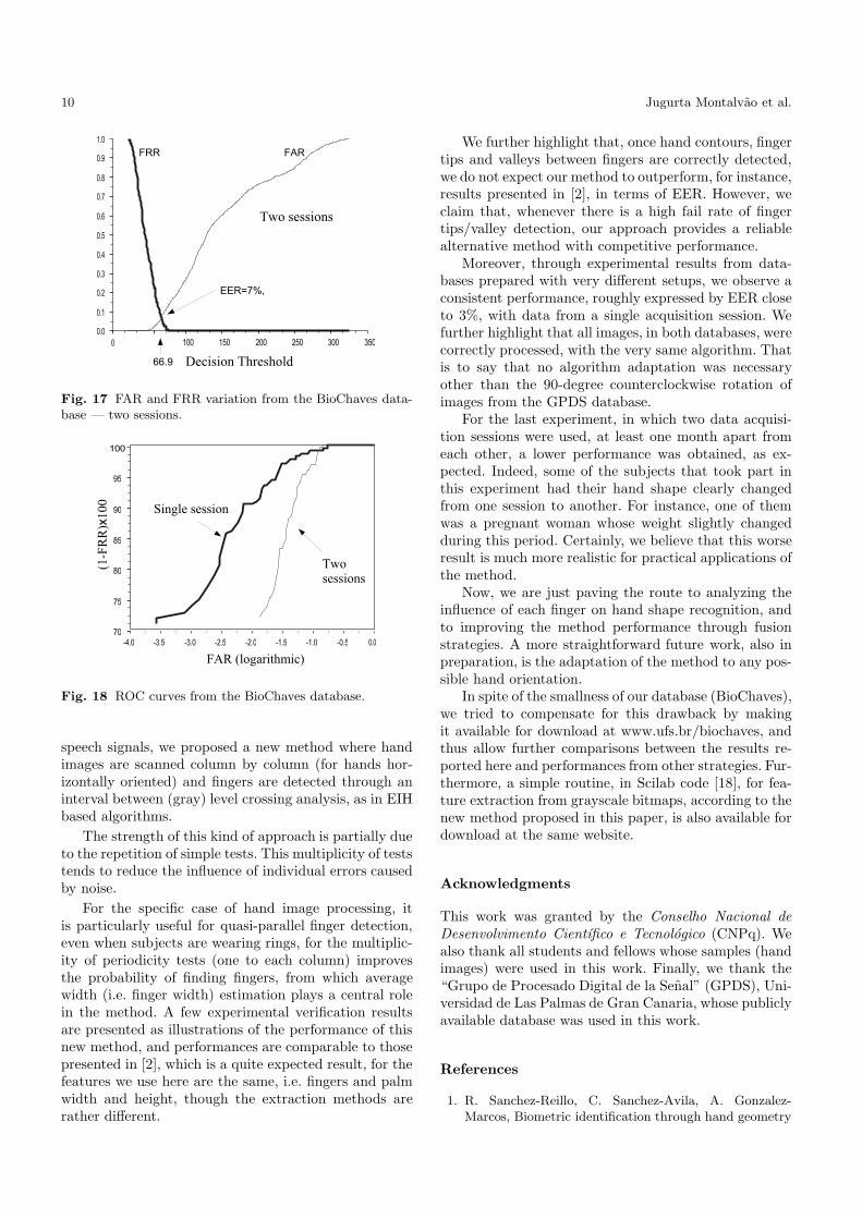
Figure 16 presents the experimental result obtainedfrom the BioChaves database, with 5 samples (images)from each subject, and 23 subjects.
Fig. 16 FAR and FRR variation from the BioChaves data-base.
In this experiment, an EER ≈ 3% was obtained,quite close to the EER ≈ 2.6% in spite of the differencebetween data acquisition setups. Moreover, as expected,the lower quality of the BioChaves images leads to alower performance, in terms of EER. We should observe,however, that EER corresponding thresholds depend onimage resolution, for distances between features are mea-sured in number of pixels.
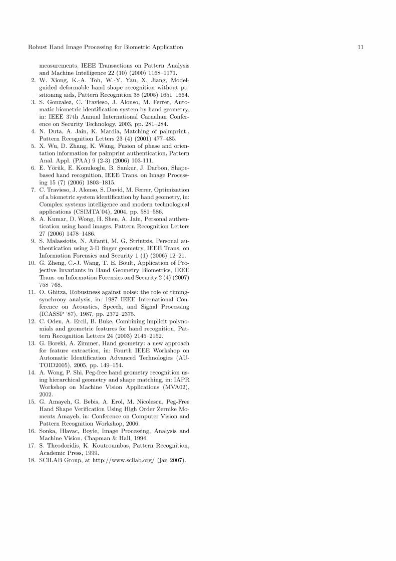
Finally, in the GPDS database it is not mentionedwhether images were acquired during a single session(i.e., all images per subject acquired at once) or other-wise. Therefore, in order to simulate a situation in whichinterrogation (still with a single image) is done at leastone month after enrollment, we asked 10 subjects (outof 23) to provide 5 more samples, at least one month af-ter the first session. Then, we again did the one-sampleenrollment/interrogation experiment. However, in thiscase, only comparisons between samples from differentsessions were allowed. It roughly corresponds to a simu-lation of interrogation done more than one month afterenrollment. Figure 17 shows the result in terms of FARand FRR, along with the corresponding EER.
In Figure 18, we can compare performances withsamples from one or two acquisition sessions.
7 Discussion and Conclusions
A new method for feature extraction from hand imageswas proposed. It was mainly motivated by the lack ofrobustness of most strategies based on contour trackingalgorithms.
Inspired by the well-known robustness of the Ensem-ble Histogram Interval (EIH) processing against back-ground noise, mainly applied to feature extraction from
10 Jugurta Montalvao et al.
Fig. 17 FAR and FRR variation from the BioChaves data-base — two sessions.
Fig. 18 ROC curves from the BioChaves database.
speech signals, we proposed a new method where handimages are scanned column by column (for hands hor-izontally oriented) and fingers are detected through aninterval between (gray) level crossing analysis, as in EIHbased algorithms.
The strength of this kind of approach is partially dueto the repetition of simple tests. This multiplicity of teststends to reduce the influence of individual errors causedby noise.
For the specific case of hand image processing, itis particularly useful for quasi-parallel finger detection,even when subjects are wearing rings, for the multiplic-ity of periodicity tests (one to each column) improvesthe probability of finding fingers, from which averagewidth (i.e. finger width) estimation plays a central rolein the method. A few experimental verification resultsare presented as illustrations of the performance of thisnew method, and performances are comparable to thosepresented in [2], which is a quite expected result, for thefeatures we use here are the same, i.e. fingers and palmwidth and height, though the extraction methods arerather different.
We further highlight that, once hand contours, fingertips and valleys between fingers are correctly detected,we do not expect our method to outperform, for instance,results presented in [2], in terms of EER. However, weclaim that, whenever there is a high fail rate of fingertips/valley detection, our approach provides a reliablealternative method with competitive performance.
Moreover, through experimental results from data-bases prepared with very different setups, we observe aconsistent performance, roughly expressed by EER closeto 3%, with data from a single acquisition session. Wefurther highlight that all images, in both databases, werecorrectly processed, with the very same algorithm. Thatis to say that no algorithm adaptation was necessaryother than the 90-degree counterclockwise rotation ofimages from the GPDS database.
For the last experiment, in which two data acquisi-tion sessions were used, at least one month apart fromeach other, a lower performance was obtained, as ex-pected. Indeed, some of the subjects that took part inthis experiment had their hand shape clearly changedfrom one session to another. For instance, one of themwas a pregnant woman whose weight slightly changedduring this period. Certainly, we believe that this worseresult is much more realistic for practical applications ofthe method.
Now, we are just paving the route to analyzing theinfluence of each finger on hand shape recognition, andto improving the method performance through fusionstrategies. A more straightforward future work, also inpreparation, is the adaptation of the method to any pos-sible hand orientation.
In spite of the smallness of our database (BioChaves),we tried to compensate for this drawback by makingit available for download at www.ufs.br/biochaves, andthus allow further comparisons between the results re-ported here and performances from other strategies. Fur-thermore, a simple routine, in Scilab code [18], for fea-ture extraction from grayscale bitmaps, according to thenew method proposed in this paper, is also available fordownload at the same website.
Acknowledgments
This work was granted by the Conselho Nacional de
Desenvolvimento Cientıfico e Tecnologico (CNPq). Wealso thank all students and fellows whose samples (handimages) were used in this work. Finally, we thank the“Grupo de Procesado Digital de la Senal” (GPDS), Uni-versidad de Las Palmas de Gran Canaria, whose publiclyavailable database was used in this work.
References
1. R. Sanchez-Reillo, C. Sanchez-Avila, A. Gonzalez-Marcos, Biometric identification through hand geometry
Robust Hand Image Processing for Biometric Application 11
measurements, IEEE Transactions on Pattern Analysisand Machine Intelligence 22 (10) (2000) 1168–1171.
2. W. Xiong, K.-A. Toh, W.-Y. Yau, X. Jiang, Model-guided deformable hand shape recognition without po-sitioning aids, Pattern Recognition 38 (2005) 1651–1664.
3. S. Gonzalez, C. Travieso, J. Alonso, M. Ferrer, Auto-matic biometric identification system by hand geometry,in: IEEE 37th Annual International Carnahan Confer-ence on Security Technology, 2003, pp. 281–284.
4. N. Duta, A. Jain, K. Mardia, Matching of palmprint.,Pattern Recognition Letters 23 (4) (2001) 477–485.
5. X. Wu, D. Zhang, K. Wang, Fusion of phase and orien-tation information for palmprint authentication, PatternAnal. Appl. (PAA) 9 (2-3) (2006) 103-111.
6. E. Yoruk, E. Konukoglu, B. Sankur, J. Darbon, Shape-based hand recognition, IEEE Trans. on Image Process-ing 15 (7) (2006) 1803–1815.
7. C. Travieso, J. Alonso, S. David, M. Ferrer, Optimizationof a biometric system identification by hand geometry, in:Complex systems intelligence and modern technologicalapplications (CSIMTA’04), 2004, pp. 581–586.
8. A. Kumar, D. Wong, H. Shen, A. Jain, Personal authen-tication using hand images, Pattern Recognition Letters27 (2006) 1478–1486.
9. S. Malassiotis, N. Aifanti, M. G. Strintzis, Personal au-thentication using 3-D finger geometry, IEEE Trans. onInformation Forensics and Security 1 (1) (2006) 12–21.
10. G. Zheng, C.-J. Wang, T. E. Boult, Application of Pro-jective Invariants in Hand Geometry Biometrics, IEEETrans. on Information Forensics and Security 2 (4) (2007)758–768.
11. O. Ghitza, Robustness against noise: the role of timing-synchrony analysis, in: 1987 IEEE International Con-ference on Acoustics, Speech, and Signal Processing(ICASSP ’87), 1987, pp. 2372–2375.
12. C. Oden, A. Ercil, B. Buke, Combining implicit polyno-mials and geometric features for hand recognition, Pat-tern Recognition Letters 24 (2003) 2145–2152.
13. G. Boreki, A. Zimmer, Hand geometry: a new approachfor feature extraction, in: Fourth IEEE Workshop onAutomatic Identification Advanced Technologies (AU-TOID2005), 2005, pp. 149–154.
14. A. Wong, P. Shi, Peg-free hand geometry recognition us-ing hierarchical geometry and shape matching, in: IAPRWorkshop on Machine Vision Applications (MVA02),2002.
15. G. Amayeh, G. Bebis, A. Erol, M. Nicolescu, Peg-FreeHand Shape Verification Using High Order Zernike Mo-ments Amayeh, in: Conference on Computer Vision andPattern Recognition Workshop, 2006.
16. Sonka, Hlavac, Boyle, Image Processing, Analysis andMachine Vision, Chapman & Hall, 1994.
17. S. Theodoridis, K. Koutroumbas, Pattern Recognition,Academic Press, 1999.
18. SCILAB Group, at http://www.scilab.org/ (jan 2007).
Related Documents


![ROBUST EAR DETECTION FOR BIOMETRIC VERIFICATIONROBUST EAR DETECTION FOR BIOMETRIC VERIFICATION 33 Typical stages of an automatic ear-based recognition system [Abaza et al., 2011] are](https://static.cupdf.com/doc/110x72/5e727f5f484ee11be50fead2/robust-ear-detection-for-biometric-robust-ear-detection-for-biometric-verification.jpg)


