HAL Id: hal-03363361 https://hal.archives-ouvertes.fr/hal-03363361 Submitted on 30 Jan 2022 HAL is a multi-disciplinary open access archive for the deposit and dissemination of sci- entific research documents, whether they are pub- lished or not. The documents may come from teaching and research institutions in France or abroad, or from public or private research centers. L’archive ouverte pluridisciplinaire HAL, est destinée au dépôt et à la diffusion de documents scientifiques de niveau recherche, publiés ou non, émanant des établissements d’enseignement et de recherche français ou étrangers, des laboratoires publics ou privés. Robust Dynamic Hand Gesture Interaction using LTE Terminals Weiyan Chen, Kai Niu, Deng Zhao, Rong Zheng, Dan Wu, Wei Wang, Leye Wang, Daqing Zhang To cite this version: Weiyan Chen, Kai Niu, Deng Zhao, Rong Zheng, Dan Wu, et al.. Robust Dynamic Hand Gesture Interaction using LTE Terminals. 2020 19th ACM/IEEE International Conference on Information Processing in Sensor Networks (IPSN), Apr 2020, Sydney, Australia. pp.109-120, 10.1109/IPSN48710.2020.00017. hal-03363361

Welcome message from author
This document is posted to help you gain knowledge. Please leave a comment to let me know what you think about it! Share it to your friends and learn new things together.
Transcript
HAL Id: hal-03363361https://hal.archives-ouvertes.fr/hal-03363361
Submitted on 30 Jan 2022
HAL is a multi-disciplinary open accessarchive for the deposit and dissemination of sci-entific research documents, whether they are pub-lished or not. The documents may come fromteaching and research institutions in France orabroad, or from public or private research centers.
L’archive ouverte pluridisciplinaire HAL, estdestinée au dépôt et à la diffusion de documentsscientifiques de niveau recherche, publiés ou non,émanant des établissements d’enseignement et derecherche français ou étrangers, des laboratoirespublics ou privés.
Robust Dynamic Hand Gesture Interaction using LTETerminals
Weiyan Chen, Kai Niu, Deng Zhao, Rong Zheng, Dan Wu, Wei Wang, LeyeWang, Daqing Zhang
To cite this version:Weiyan Chen, Kai Niu, Deng Zhao, Rong Zheng, Dan Wu, et al.. Robust Dynamic HandGesture Interaction using LTE Terminals. 2020 19th ACM/IEEE International Conference onInformation Processing in Sensor Networks (IPSN), Apr 2020, Sydney, Australia. pp.109-120,�10.1109/IPSN48710.2020.00017�. �hal-03363361�
Robust Dynamic Hand Gesture Interaction using LTE Terminals
Weiyan ChenKey Laboratory of High Confidence
Software Technologies (MoE)
Department of Computer Science,
School of EECS, Peking University
Beijing, China
Kai NiuKey Laboratory of High Confidence
Software Technologies (MoE)
Department of Computer Science,
School of EECS, Peking University
Beijing, China
Deng ZhaoChina University of Geosciences
(Beijing)
Beijing, China
Rong ZhengMcMaster University
Harbin Institute of Technology
(Shenzhen)
Hamilton, Canada / Shenzhen, China
Dan WuPeking University
Beijing, China
Wei WangNanjing University
Nanjing, China
Leye WangPeking University
Beijing, China
Daqing Zhang∗
Peking University
Telecom SudParis
Beijing, China / Evry, France
ABSTRACT
Device-free hand gesture is one of the most natural ways to interact
with everyday objects. However, existing WiFi-based gesture recog-
nition solutions are typically restricted to indoor environments due
to limited outdoor coverage. Furthermore, to achieve high sampling
rates, they may interfere with normal data transmissions. In this pa-
per, we aim to develop a robust dynamic gesture interaction system
that can be ubiquitously deployed using Long-term Evolution (LTE)
mobile terminals. Through both empirical studies and in-depth
analysis using the Fresnel zone model, we reveal the key factors
that contribute to the repeatability and discernibility of gestures.
We show that the optimal location and orientation to perform ges-
tures indeed exist and can be identified without prior knowledge
of the position of LTE base stations (BSs) relative to a terminal.
Guided by the design principles derived from Fresnel zone char-
acteristics around a 4G terminal, we design highly repeatable and
discernible gestures with salient received signal profiles. A gesture
interaction system has been developed and implemented to achieve
robust recognition with this careful design. Extensive experiments
have been conducted in both indoor and outdoor environments, for
different relative placements of mobile terminal and BS, and with
different users. The proposed system can automatically identify the
direction of BSs with a median error of less than 15 degrees and
achieve gesture recognition accuracy as high as 98% in all scenarios
without the need to acquire any training data.
∗Corresponding author
CCS CONCEPTS
•Human-centered computing→Ubiquitous computing;Ac-
tivity centered design;Gestural input; Ubiquitous and mobile com-
puting systems and tools; • Information systems→Mobile infor-
mation processing systems.
KEYWORDS
LTE signal, Gesture recognition, CSI ratio, Device-free sensing,
Channel State Information
1 INTRODUCTION
Device-free hand gesture offers one of the most natural ways for
Human-Computer Interaction (HCI). It allows users to interact with
everyday objects and wearable devices of limited form factors in a
non-intrusive manner. Hand gestures can be conceptually divided
into static gestures and dynamic gestures. Dynamic hand gestures
usually provide richer information than static gestures because of
the incorporation of motion. Existing approaches to device-free
hand gesture recognition mainly fall into four categories: vision-
based [13, 23], acoustic-based [22, 28], Radio Frequency (RF) based
using specialized devices such as mmWave and Ultra-wideband
radars [17, 38] and WiFi-based solutions [2, 4, 15, 37, 40]. Among
them, WiFi-based solutions utilize Channel State Information (CSI)
extracted from WiFi signals received at a mobile terminal to recog-
nize various hand gestures. Such solutions are attractive due to their
low costs and no need for hardwaremodification. Despite successful
experimental demonstrations in several application scenarios, WiFi-
based solutions are typically restricted to indoor environments due
to limited outdoor coverage, and may interfere with normal data
transmissions to acquire continuous, uniform and high sampling
rates. Furthermore, there lacks a principled way to design RF-based
109
2020 19th ACM/IEEE International Conference on Information Processing in Sensor Networks (IPSN)
978-1-7281-5497-8/20/$31.00 ©2020 IEEEDOI 10.1109/IPSN48710.2020.00017
Authorized licensed use limited to: Telecom SudParis ( Frmly Telecom et management SudParis INT). Downloaded on October 03,2021 at 19:56:16 UTC from IEEE Xplore. Restrictions apply.
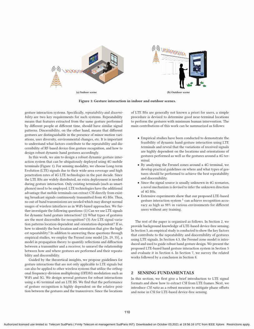
(a) Indoor scene (b) Outdoor scene
Figure 1: Gesture interaction in indoor and outdoor scenes.
gesture interaction systems. Specifically, repeatability and discerni-
bility are two key requirements for such systems. Repeatability
means that features extracted from the same gesture performed
by different people at different time, should have similar signal
patterns. Discernibility, on the other hand, means that different
gestures are distinguishable in the presence of minor motion vari-
ations, user diversity, environmental changes, etc. It is important
to understand what factors contribute to the repeatability and dis-
cernibility of RF-based device-free gesture recognition, and how to
design robust dynamic hand gestures accordingly.
In this work, we aim to design a robust dynamic gesture inter-
action system that can be ubiquitously deployed using 4G mobile
terminals (Figure 1). For sensing modality, we choose Long-term
Evolution (LTE) signals due to their wide-area coverage and high
penetration rates of 4G LTE technologies in the past decade. Since
the LTE BSs are widely distributed, no extra deployment is needed
during gesture interaction. Only existing terminals (such as smart-
phones) need to be employed. LTE technologies have the additional
advantage that mobile terminals can extract CSI directly from exist-
ing broadcast signals continuously transmitted from 4G BSs. Thus,
no out-of-band transmissions are needed which may disrupt normal
usages of wireless interfaces as in WiFi-based approaches. We fur-
ther investigate the following questions: (1) Can we use LTE signals
for dynamic hand gesture interaction? (2) What types of gestures
are the most discernible for recognition? (3) Are LTE signal varia-
tion patterns location-dependent and orientation-dependent? If so,
how to identify the best location and orientation that give the high-
est repeatability? In addition to answering these questions through
empirical studies, we employ the Fresnel zone model [26, 29, 35], a
model in propagation theory to quantify reflections and diffraction
between a transmitter and a receiver, to unravel the relationship
between how and where gestures are performed and their repeata-
bility and discernibility.
Guided by the theoretical insights, we propose guidelines for
gesture interactions that are not only applicable to LTE signals but
can also be applied to other wireless systems that utilize the orthog-
onal frequency-division multiplexing (OFDM) modulation such as
WiFi and 5G. We design several gestures for robust interactions
using a 4G terminal and an LTE BS. We find that the performance
of gesture recognition is highly dependent on the relative posi-
tion between the gestures and the transceivers. Since the locations
of LTE BSs are generally not known a priori for users, a simple
procedure is devised to determine good near-terminal locations
to perform the gestures with minimum human intervention. The
main contributions of this work can be summarized as follows:
• Empirical studies have been conducted to demonstrate the
feasibility of dynamic hand gesture interaction using LTE
terminals and reveal that the variations of received signals
are highly dependent on the locations and orientations of
gestures performed as well as the gestures around a 4G ter-
minal.
• By analyzing the Fresnel zones around a 4G terminal, we
develop practical guidelines on where and what types of ges-
tures should be performed to achieve the best repeatability
and discernibility.
• Since the signal source is usually unknown in 4G scenarios,
a novel mechanism is devised to infer the unknown direction
of 4G BSs.
• Extensive experiments show that our proposed LTE-based
gesture interaction system 1 can achieve recognition accu-
racy as high as 98% in various environments for different
users without any training.
The rest of the paper is organized as follows. In Section 2, we
provide background knowledge of LTE-based device-free sensing.
In Section 3, an empirical study is conducted to show the key factors
that contribute to the repeatability and discernibility of gestures
using LTE signals. In Section 4.3, the Fresnel zone model is intro-
duced and used to guide robust hand gesture design. We present the
proposed LTE-based hand gesture interaction system in Section 5
and evaluate it in Section 6. In Section 7, we survey the related
works followed by a conclusion in Section 8.
2 SENSING FUNDAMENTALS
In this section, we first give a brief introduction to LTE signal
formats and show how to extract CSI from LTE frames. Next, we
introduce CSI ratio as a robust measure to mitigate phase offsets
and noise in CSI for LTE-based device-free sensing.
110
Authorized licensed use limited to: Telecom SudParis ( Frmly Telecom et management SudParis INT). Downloaded on October 03,2021 at 19:56:16 UTC from IEEE Xplore. Restrictions apply.

Extended CPOFDM symbol
OFDM symbol
One slot
One subframe
One frame10ms 10ms10ms
#0 #2#1 #4#3 #5 #7#6 #9#8
0.5ms0.5ms Normal CP
(a) Time Domain of LTE signals.
1 subframe (2 slots, 14 OFDM symbols) 12 subcarriers (1 Resource Block)
0 1 2 3 4 5 6 0 1 2 3 4 5 6Time Domain
Frequency Dom
ain
R1 R1
R1
R1 R1
R1 R1
R0 R0
R0 R0
R0 R0
R0 R0
R3
R3
R3
R3
R2
R1 R2
R2
R2
(b) Location layouts of CRSs intime-frequency resources of LTEsignals.
Figure 2: The basic structure of LTE signals.
2.1 LTE Primer
In LTE systems, BSs transmit radio frames with a fixed duration of
10ms to 4G terminals [1]. As shown in Figure 2a, every radio frame is
subdivided into 10 subframes of a duration of 1ms, each containing
two 0.5ms slots. Depending on the configuration of BSs, each slot
consists of six (in the case of extended Cyclic Prefix (CP)) or seven
OFDM symbols (in the case of normal CP). In the frequency domain,
an OFDM symbol occupies a series of subcarriers at a frequency
interval of Δ𝑓 = 15𝑘𝐻𝑧. Thus, the basic scheduling unit in LTEis called Resource Block (RB), which contains 12 subcarriers in
frequency domain and lasts one slot (0.5ms) in the time domain, as
shown in Figure 2b. In each downlink RB (from a BS to a terminal),
a Cell-Specific Reference Signal (CRS) with predefined symbols
is transmitted by an LTE BS at four different locations with two
CRSs separated by six subcarriers. For example, 𝑅0, 𝑅1, 𝑅2 and 𝑅3 inFigure 2b are four common location layouts of CRSs in LTE systems.
Therefore, a CRS forms a dense time-frequency grid at a fixed time
and frequency intervals. It can be used to estimate channel state to
improve the quality of communication.
2.2 Extracting CSI from LTE Signals
Channel state estimation is an effective means to improve system
performance in wireless communication. Suppose that a BS trans-
mits signal𝑋 (𝑓 , 𝑡) on a given subcarrier 𝑓 at time 𝑡 in the frequencydomain. The CSI𝐻 (𝑓 , 𝑡) from the BS to a terminal can be estimatedfrom the frequency-domain received signal 𝑌 (𝑓 , 𝑡) as follows:
𝐻 (𝑓 , 𝑡) =𝑌 (𝑓 , 𝑡)
𝑋 (𝑓 , 𝑡), (1)
which is a complex-valued channel measurement. It represents
how the environment around the transmitter and receiver (e.g.,
multipath effect, moving objects) affects the amplitude and phase
of received LTE signals.
The LTE signal arriving at a receiving antenna along 𝑁 differentpaths can be grouped into two components: those along static paths
and those along a dominant dynamic path [16, 26, 27], as shown in
Figure 3a. The total CSI is the linear superposition of signals on all
1A live demo video is shown at https://youtu.be/e_OiQVkDExk.
LoS Path
ba
Transmitter
Receiver
Reflector
Object
Dynamic Path:Reflected by hand
Static Paths
(a)
Hs
I
Hd
Combined CSI
Q
a
b
Sinusoid-like waveform
(b)
Figure 3: 4G scenarios and the CSI in a complex plane. (a)
The LTE signal arrives at a receiving antenna alongmultiple
paths. (b) CSI changes in a complex plane.
paths, given by
𝐻 (𝑓 , 𝑡) = 𝐻𝑠 (𝑓 , 𝑡) + 𝐻𝑑 (𝑓 , 𝑡)
= 𝐻𝑠 (𝑓 , 𝑡) + �𝑎(𝑓 , 𝑡) · 𝑒−𝑗2𝜋𝑑 (𝑡 )𝜆 ,
(2)
where𝐻𝑠 (𝑓 , 𝑡) is the static path component including signals throughthe Line-of-Sight (LoS) path and reflected paths from static objects,
�𝑎(𝑓 , 𝑡) is the complex-valued representation of attenuation andinitial phase offset of the dynamic path component 𝐻𝑑 (𝑓 , 𝑡). Thelatter varies with 𝑑 (𝑡), the length of the reflected path induced bya moving object. 𝜆 = 𝑐/𝑓 is the wavelength for the radio signalwith frequency 𝑓 , and 𝑐 is the speed of light. In the complex plane(Figure 3b), both 𝐻𝑠 (𝑓 , 𝑡) and 𝐻𝑑 (𝑓 , 𝑡) can be represented as vec-tors. 𝐻𝑠 (𝑓 , 𝑡) is a constant, while 𝐻𝑑 (𝑓 , 𝑡) varies with the dynamic
path length 𝑑 (𝑡). 𝑒−𝑗2𝜋𝑑 (𝑡 )/𝜆 is the phase shift on the dynamicpath. Whenever the movement of the object introduces one wave-
length change in the dynamic path length, the corresponding phase
changes 2𝜋 , and 𝐻𝑑 (𝑓 , 𝑡) rotates a cycle, generating a sinusoid-likewaveform.
However, since the clocks on the BS and the terminal are gener-
ally not synchronized, the received CSI can be further characterized
as:
𝐻 (𝑓 , 𝑡) = 𝛼𝑛𝑜𝑖𝑠𝑒 (𝑓 , 𝑡)𝑒−𝑗 ·𝜃𝑜𝑓 𝑓 𝑠𝑒𝑡 (𝐻𝑠 (𝑓 , 𝑡) + 𝐻𝑑 (𝑓 , 𝑡)) , (3)
where 𝛼𝑛𝑜𝑖𝑠𝑒 denotes the noise in amplitude, 𝑒−𝑗 ·𝜃𝑜𝑓 𝑓 𝑠𝑒𝑡 denotes the
random phase offset in each CSI sample due to Carrier Frequency
Offset (CFO), Sample Frequency Offset (SFO) [32], and so on. These
phase offsets result in the randomness of phase information in CSI
– a key challenge for sensing human activities using LTE signals.
2.3 CSI Ratio
To eliminate the randomness of phase offsets in CSI, we note that
modern mobile devices like smartphones support MIMO technol-
ogy [5]. Since the antennas in the same LTE adapter share the same
clock, they have the same CFO, SFO and so on. Thus, we introduce
the CSI ratio [15, 33] between two antennas as a new base signal
for LTE-based sensing to suppress the impulse noise in amplitude
and eliminate these phase random offsets in CSI of LTE signals.
111
Authorized licensed use limited to: Telecom SudParis ( Frmly Telecom et management SudParis INT). Downloaded on October 03,2021 at 19:56:16 UTC from IEEE Xplore. Restrictions apply.
Sample
200 400 600 800
1A
mpl
itude
Sample0 200 400 600 800 1000
Phas
e
0
- 1000
Phas
e
0
-
CSI of Antenna 1
CSI of Antenna 2 1
0.40
0.8 0.6A
mpl
itude
(a)
Sample0 200 400 600 800 1000
1 1.1
0.9Am
plitu
de
Sample200 400 600 800 1000
1
1.3
1.1 1.2
Phas
e
0
Amplitude of
Phase of
(b)
0.2 0.3 0.4 0.5 0.6I
0.8
0.9
1
1.1
Q
(c)
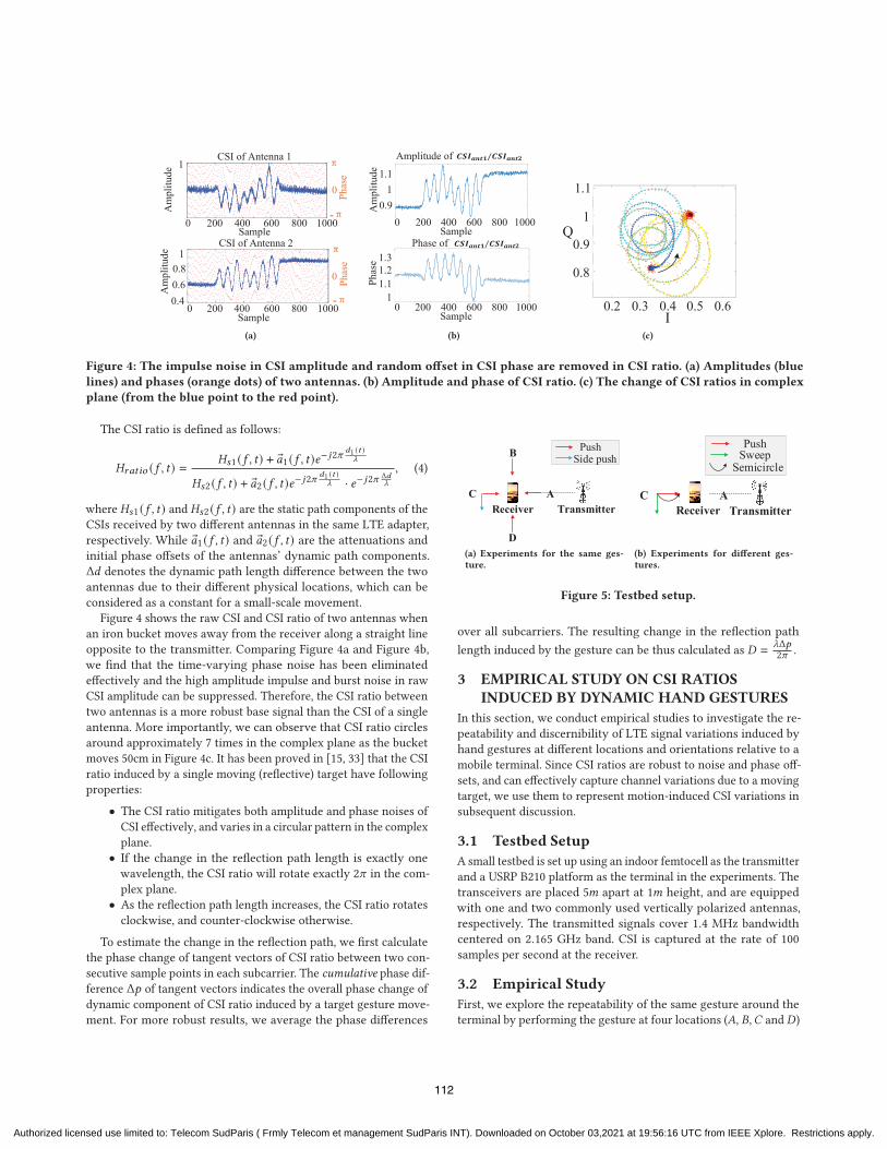
Figure 4: The impulse noise in CSI amplitude and random offset in CSI phase are removed in CSI ratio. (a) Amplitudes (blue
lines) and phases (orange dots) of two antennas. (b) Amplitude and phase of CSI ratio. (c) The change of CSI ratios in complex
plane (from the blue point to the red point).
The CSI ratio is defined as follows:
𝐻𝑟𝑎𝑡𝑖𝑜 (𝑓 , 𝑡) =𝐻𝑠1 (𝑓 , 𝑡) + �𝑎1 (𝑓 , 𝑡)𝑒
−𝑗2𝜋𝑑1 (𝑡 )
𝜆
𝐻𝑠2 (𝑓 , 𝑡) + �𝑎2 (𝑓 , 𝑡)𝑒−𝑗2𝜋
𝑑1 (𝑡 )𝜆 · 𝑒−𝑗2𝜋
Δ𝑑𝜆
, (4)
where 𝐻𝑠1 (𝑓 , 𝑡) and 𝐻𝑠2 (𝑓 , 𝑡) are the static path components of theCSIs received by two different antennas in the same LTE adapter,
respectively. While �𝑎1 (𝑓 , 𝑡) and �𝑎2 (𝑓 , 𝑡) are the attenuations andinitial phase offsets of the antennas’ dynamic path components.
Δ𝑑 denotes the dynamic path length difference between the twoantennas due to their different physical locations, which can be
considered as a constant for a small-scale movement.
Figure 4 shows the raw CSI and CSI ratio of two antennas when
an iron bucket moves away from the receiver along a straight line
opposite to the transmitter. Comparing Figure 4a and Figure 4b,
we find that the time-varying phase noise has been eliminated
effectively and the high amplitude impulse and burst noise in raw
CSI amplitude can be suppressed. Therefore, the CSI ratio between
two antennas is a more robust base signal than the CSI of a single
antenna. More importantly, we can observe that CSI ratio circles
around approximately 7 times in the complex plane as the bucket
moves 50cm in Figure 4c. It has been proved in [15, 33] that the CSI
ratio induced by a single moving (reflective) target have following
properties:
• The CSI ratio mitigates both amplitude and phase noises of
CSI effectively, and varies in a circular pattern in the complex
plane.
• If the change in the reflection path length is exactly one
wavelength, the CSI ratio will rotate exactly 2𝜋 in the com-plex plane.
• As the reflection path length increases, the CSI ratio rotates
clockwise, and counter-clockwise otherwise.
To estimate the change in the reflection path, we first calculate
the phase change of tangent vectors of CSI ratio between two con-
secutive sample points in each subcarrier. The cumulative phase dif-
ference Δ𝑝 of tangent vectors indicates the overall phase change ofdynamic component of CSI ratio induced by a target gesture move-
ment. For more robust results, we average the phase differences
TransmitterAC
D
B Push
Receiver
Side push
(a) Experiments for the same ges-ture.
SweepPush
CReceiver
Semicircle
TransmitterA
(b) Experiments for different ges-tures.
Figure 5: Testbed setup.
over all subcarriers. The resulting change in the reflection path
length induced by the gesture can be thus calculated as 𝐷 = 𝜆Δ𝑝2𝜋 .
3 EMPIRICAL STUDY ON CSI RATIOSINDUCED BY DYNAMIC HAND GESTURES
In this section, we conduct empirical studies to investigate the re-
peatability and discernibility of LTE signal variations induced by
hand gestures at different locations and orientations relative to a
mobile terminal. Since CSI ratios are robust to noise and phase off-
sets, and can effectively capture channel variations due to a moving
target, we use them to represent motion-induced CSI variations in
subsequent discussion.
3.1 Testbed Setup
A small testbed is set up using an indoor femtocell as the transmitter
and a USRP B210 platform as the terminal in the experiments. The
transceivers are placed 5𝑚 apart at 1𝑚 height, and are equippedwith one and two commonly used vertically polarized antennas,
respectively. The transmitted signals cover 1.4 MHz bandwidthcentered on 2.165 GHz band. CSI is captured at the rate of 100samples per second at the receiver.
3.2 Empirical Study
First, we explore the repeatability of the same gesture around the
terminal by performing the gesture at four locations (𝐴, 𝐵,𝐶 and 𝐷)
112
Authorized licensed use limited to: Telecom SudParis ( Frmly Telecom et management SudParis INT). Downloaded on October 03,2021 at 19:56:16 UTC from IEEE Xplore. Restrictions apply.
I
Q
(a) Push at𝐴
I
Q
(b) Push at 𝐵
I
Q
(c) Push at𝐶
I
Q
(d) Push at 𝐷
I
Q
(e) Side push at𝐶
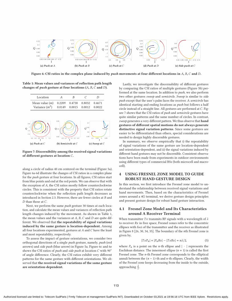
Figure 6: CSI ratios in the complex plane induced by pushmovements at four different locations in 𝐴, 𝐵, 𝐶 and 𝐷 .
Table 1: Mean values and variances of reflection path length
changes of push gesture at four locations (𝐴, 𝐵, 𝐶 and 𝐷).
Location 𝐴 𝐵 𝐶 𝐷
Mean value (𝑚) 0.2209 0.4738 0.8032 0.4671
Variance (𝑚2) 0.0149 0.0015 0.0012 0.0022
I
Q
(a) Push at𝐶
I
Q
(b) Semicircle at𝐶
I
Q
(c) Sweep at𝐶
Figure 7: Discernibility among the received signal variations
of different gestures at location 𝐶.
along a circle of radius 40 cm centered on the terminal (Figure 5a).
Figure 6a-6d illustrate the changes of CSI ratios in a complex plane
for the push gesture at four locations. In all figures, CSI ratios start
from blue points and end at the red points. We can observe that with
the exception of 𝐴, the CSI ratios mostly follow counterclockwisecircles. This is consistent with the property that CSI ratios rotate
counterclockwise when the reflection path length decreases as
introduced in Section 2.3. However, there are fewer circles at 𝐵 and𝐷 than those at 𝐶 .Next, we perform the same push gesture 30 times at each loca-
tion, and calculate the mean values and variances of reflection path
length changes induced by the movement. As shown in Table 1,
the mean values and the variances at 𝐴, 𝐵, 𝐶 and 𝐷 are quite dif-ferent. We observed that the repeatability of signal variations
induced by the same gesture is location-dependent. Among
all four locations experimented, gestures at 𝐴 and 𝐶 have the leastand most repeatability, respectively.
To assess the impact of gesture orientations, we consider two
orthogonal directions of a single push gesture, namely, push (red
arrows) and side push (blue arrow) in Figure 5a. Figure 6c and 6e
shows the CSI ratios of push and side push at location 𝐶 with 90◦
of angle difference. Clearly, the CSI ratios exhibit very different
patterns for the same gesture with different orientations. We ob-
served that the received signal variations of the same gesture
are orientation-dependent.
Lastly, we investigate the discernability of different gestures
by comparing the CSI ratios of multiple gestures (Figure 5b) per-
formed at the same location. In addition to push, we also perform
two other gestures sweep and semicircle. Sweep is similar to side
push except that the user’s palm faces the receiver. A semicircle has
identical starting and ending locations as push but follows a half
circle instead of a straight line. All gestures are performed at𝐶 . Fig-ure 7 shows that the CSI ratios of push and semicircle gestures have
quite similar patterns and the same number of circles. In contrast,
sweep generates a very different pattern.We thus observe thathand
gestures of different spatial motions do not always generate
distinctive signal variation patterns. Since some gestures are
easier to be differentiated than others, special considerations are
needed to design highly discernible gestures.
In summary, we observe empirically that i) the repeatability
of signal variations of the same gesture are location-dependent
and orientation-dependent, and ii) the signal variations induced by
different hand gestures may not be discernible. Consistent observa-
tions have been made from experiments in outdoor environments
using different types of commercial BSs (both microcell and macro-
cell).
4 USING FRESNEL ZONE MODEL TO GUIDEROBUST HAND GESTURE DESIGN
In this section, we first introduce the Fresnel zone model to un-
derstand the relationship between received signal variations and
hand movements. Then, based on the characteristics of Fresnel
zones around a 4G terminal, we derive gesture design principles
and present gesture design for robust hand gesture interaction.
4.1 Fresnel Zone Model and Its Characteristicsaround A Receiver Terminal
When transmitter 𝑇𝑥 transmits RF signals with a wavelength of 𝜆to receiver 𝑅𝑥 in free space, Fresnel zones refer to the concentricellipses with foci of the transmitter and the receiver as illustrated
in Figure 8 [26, 30, 34, 35]. The boundary of the 𝑛th Fresnel zone isgiven by,
|𝑇𝑥𝑃𝑛 | + |𝑃𝑛𝑅𝑥 | − |𝑇𝑥𝑅𝑥 | = 𝑛𝜆/2, (5)
where 𝑃𝑛 is a point on the 𝑛-th ellipse and | · | represents the
Euclidean distance. The innermost ellipse (𝑛 = 1) is called the firstFresnel zone. The 𝑛-th Fresnel zone corresponds to the ellipticalannuli between the (𝑛 − 1)-th and 𝑛-th ellipses. Clearly, the widthof the Fresnel zone keeps decreasing from the inside to the outside,
approaching 𝜆2 .
113
Authorized licensed use limited to: Telecom SudParis ( Frmly Telecom et management SudParis INT). Downloaded on October 03,2021 at 19:56:16 UTC from IEEE Xplore. Restrictions apply.

Figure 8: Geometry of the Fresnel zone and its distribution around a terminal.
Table 2: Design principles for robust gestures
Property of Fresnel Zones CSI Ratio Variation Pattern Design Principles
Diffraction effects in 1st Fresnel Zone (the
red area)
Poor repeatability of CSI ratio signal varia-
tions
(I) Avoiding gesturing in red region
Evenly spaced Fresnel zones in the blue area
due to reflection effects
Good repeatability of CSI ratio signal varia-
tions
(II) Gesturing in the blue area
Crossing two adjacent Fresnel zones corre-
sponds to a reflection path change of one
wavelength
The dynamic component of CSI ratio moves
one cycle in the complex plane
(III) Hand moving distance and patterns can
be easily profiled when the hand crosses mul-
tiple Fresnel zones perpendicularly
When a target is in the first Fresnel zone, diffraction is dom-
inant [35, 36]. The gain of the received signal is the sum of the
energy bypassing the target, which depends on the size and posi-
tion of the target. In contrast, reflection becomes dominant outside
the first Fresnel zone. Under the assumption that there is only one
dominant reflection path from a target, the received signal is the
aggregation of the two signals along the direct path and reflected
path. Since reflection introduces a phase shift of 𝜋 , when the targetis located in the boundaries of odd Fresnel zones (or even Fres-
nel zones), the two signals have the same phases (or destructive
phases) but different amplitudes, leading to superposed stronger
received signals (or weaker received signals). As illustrated in Fig-
ure 8, when a hand continuously crosses outwards (or inwards) the
boundaries of Fresnel zones, the amplitudes of the received signal
exhibit a sinusoid pattern, while its phase increases (or decreases)
with the reflection path length. Whenever the length of the reflec-
tion path changes by 𝜆, the phase of dynamic vector changes by 2𝜋 .By the definition of CSI ratio in Section 2.3, 𝜆 reflection path lengthchange results in 2𝜋 phase change in the dynamic component, orequivalently rotation of a complete circle. Furthermore, when the
reflection path increases, the dynamic component rotates clockwise,
and counter-clockwise vice versa. The exact pattern of the received
signal variations induced by a hand gesture depends on the number
and direction of the Fresnel zone crossed.
4.2 Implication on Gesture Design
As shown in Figure 8, the Fresnel zones around a terminal (𝑅𝑥 ) areunevenly distributed. Such an uneven distribution has a number
of important implications on gesture design. First, in the red area
centered around the first Fresnel zone, where diffraction dominates
when a hand moves in that area, any slight deviation of a hand
moving trajectory leads to a significant difference in signal variation
patterns at the receiver. In contrast, as observed in Section 3.2, in the
high-density Fresnel zone area (the blue area in Figure 8), similar
hand moving trajectories crossing the Fresnel zones lead to similar
signal variation patterns at the receiver due to the even spacing of
Fresnel zones there. Second, in the dense Fresnel zones, given the
same hand moving distance, when the hand moves perpendicular
to the boundaries of Fresnel zones, more zones can be crossed.
Equivalently, there are more phase changes in CSI or CSI ratio.
Third, as observed in Section 3.2, when performing the same gesture
at the same location but different orientations, it is expected that the
moving trajectories cross different numbers of Fresnel zones. As a
result, they induce different signal variations. Lastly, to distinguish
different gestures, we would like to have repeatable signal variation
patterns for individual gestures, but very different signal variation
patterns among different gestures, e.g., crossing different numbers
of Fresnel zones or in different directions.
To this end, we summarize the key properties of the Fresnel zones
around a 4G terminal and the corresponding guiding principles for
robust gesture design in Table 2.
4.3 Robust Hand Gestures
From the design principles I and II, we know that for better repeata-
bility, gestures should be performed in the blue area (called the
optimal area). Principle III implies that gesture movements should
be perpendicular to the Fresnel zone boundaries (called the optimal
orientation) and cross the Fresnel zone continuously. What remains
to tackle is to design multiple discernible gestures. We propose the
template of gesture interaction which can be used in both indoor
and outdoor environments.
114
Authorized licensed use limited to: Telecom SudParis ( Frmly Telecom et management SudParis INT). Downloaded on October 03,2021 at 19:56:16 UTC from IEEE Xplore. Restrictions apply.
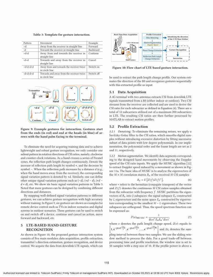
Table 3: Template for gesture interaction.
Pattern Movement Example
+d Away from the receiver in straight line Forward
-d Towards the receiver in straight line Backward
+d-d Away from and towards the receiver in
straight line
Continue
-d+d Towards and away from the receiver in
straight line
Cancel
+d-d+d-d Away from and towards the receiver twice
in circle line
Switch on
-d+d-d+d Towards and away from the receiver twice
in circle line
Switch off
Receiver
LOS
Receiver
LOS
Transmitter
-d+d+d-d
Hand
+d-d+d-d -d+d-d+d
+d -d
Switch on Switch offCancelContinue
Forward Backward
Figure 9: Example gestures for interaction. Gestures start
from the ends (in red) and end at the heads (in blue) of ar-
rows with the hand palm facing to the terminal.
To eliminate the need for acquiring training data and to achieve
lightweight and robust gesture recognition, we only consider one
salient pattern in rotation directions of CSI ratios, namely, clockwise
and counter-clock rotations. As a hand crosses a series of Fresnel
zones, the reflection path length changes continuously. Denote the
increase of reflection path length by symbol +, and the decrease by
symbol −. When the reflection path increases by a distance 𝑑 (e.g.,when the hand moves away from the receiver), the corresponding
signal variation pattern is denoted by +𝑑 . Similarly, one can defineother unique signal variation patterns such as (−𝑑), (+𝑑 − 𝑑), (+𝑑 −
𝑑 + 𝑑), etc. We show six basic signal variation patterns in Table 3.Noted that more gestures can be designed by combining different
directions and distances.
By mapping well-defined signal variation patterns to different
gestures, we can achieve gesture recognition with high accuracy
without training. In Figure 9, six gestures are shown as examples for
remote device control such as TVs in indoor scenarios and digital
screens in outdoor scenarios. These gestures can be used to switch
on and switch off a device, continue and cancel an action, move
forward and backward, etc.
5 LTE-BASED HAND GESTURERECOGNITION
As shown in Figure 10, the proposed gesture interaction system
consists of five main modules: data acquisition, profile extraction,
transmitter’s direction estimation, gesture recognition, and device
control. We acquire the data from downlink LTE signals, which can
Real-Time Data Acquisition
Base Station
4G Device
Hand Gesture
LTE CSI Stream
Data DenoisingProfile Extraction
Identifying the direction of the LTE Base Station
Motion SegmentationDoppler Speed
Gesture Recognition
Interaction
Phase Change Extraction
Reflection Path Length Change Extraction
Figure 10: Flow chart of LTE-based gesture interaction.
be used to extract the path length change profile. Our system esti-
mates the direction of the BS and recognizes gestures sequentially
with this extracted profile as input.
5.1 Data Acquisition
A 4G terminal with two antennas extracts CSI from downlink LTE
signals transmitted from a BS (either indoor or outdoor). Two CSI
streams from the receiver are collected and are used to derive the
CSI ratio for each subcarrier as defined in Equation (4). There are a
total of 12 subcarriers utilized out of a maximum 200 subcarriers
in LTE. The resulting CSI ratios are then further processed by
MATLAB to extract motion profiles.
5.2 Profile Extraction
5.2.1 Denoising. To eliminate the remaining noises, we apply a
Savitzky-Golay filter to the CSI ratios, which smooths digital sam-
ples without introducing excessive distortion by fitting successive
subset of data points with low degree polynomials. In our imple-
mentation, the polynomial order and the frame length are set as 2
and 11, respectively.
5.2.2 Motion segmentation. We identify data segments correspond-
ing to the designed hand movements by observing the Doppler
speed of the CSI ratio inputs. We apply the MUSIC algorithm [12]
to extract Doppler speed induced by a movement as shown in Fig-
ure 11a. The basic idea of MUSIC is to analyze the eigenvectors of
the𝑀 ×𝑀 correlation matrix 𝑅𝑥 of the received𝑀 CSI samples:
𝑅𝑥 = 𝐸[𝑍 (𝑓 )𝑍 (𝑓 )∗
], (6)
where ∗ refers to the hermitian (conjugate transpose) of the vector
and 𝑍 (𝑓 ) denotes the continuous 𝑀 CSI ratios samples obtainedfrom the subcarrier with frequency 𝑓 . MUSIC partitions the eigen-vectors of 𝑅𝑥 into 2 subspaces: the signal subspace 𝐸𝑠 constructedby 𝐿 eigenvectors and the noise space 𝐸𝑛 constructed by eigenvec-tors corresponding to the smallest𝑀 − 𝐿 eigenvalues. These twosubspaces are orthogonal. Thus, the speed spectrum function can
be expressed as:
𝑃 (𝑣)𝑀𝑈𝑆𝐼𝐶 =1
�𝑎(𝑣)∗𝐸𝑛𝐸𝑛∗ �𝑎(𝑣), (7)
where 𝑣 denotes the path length change speed, �𝑎(𝑣) equals to[1, e−j2𝜋f
vΔt2c , e−j2𝜋f
vΔt3c , ..., e−j2𝜋f
vΔtMc
]and Δ𝑡𝑖 denotes the sam-
pling interval between these two samples. We use the sliding win-
dow method to process the data. For a good trade-off between
processing time and profile resolution, the window size is set to
50 samples with a step size of 10. If the profile power is above a
115
Authorized licensed use limited to: Telecom SudParis ( Frmly Telecom et management SudParis INT). Downloaded on October 03,2021 at 19:56:16 UTC from IEEE Xplore. Restrictions apply.
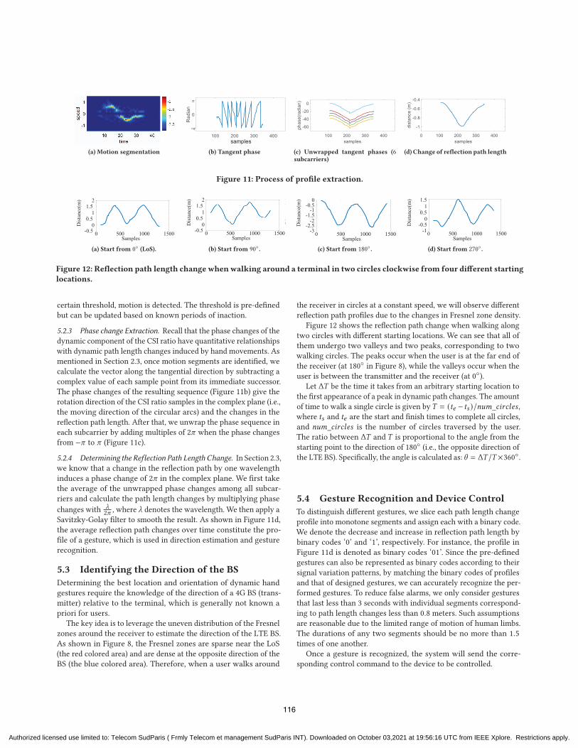
(a) Motion segmentation
samples
(b) Tangent phase (c) Unwrapped tangent phases (6subcarriers)
(d) Change of reflection path length
Figure 11: Process of profile extraction.
Dist
ance
(m)
500 1000 1500-0.50
0.51
1.52
Samples0
(a) Start from 0◦ (LoS).
Di
()
Dist
ance
(m)
500 1000 1500-0.50
0.51
1.52
Samples0
(b) Start from 90◦.
Dist
ance
(m)
500 1000 1500Samples
0
-1 -0.5
0
-1.5-2
-3 -2.5
(c) Start from 180◦.
Dist
ance
(m)
1000 1500
1 1.5
Samples0
-0.50
0.5
-1 500
(d) Start from 270◦.
Figure 12: Reflection path length change whenwalking around a terminal in two circles clockwise from four different starting
locations.
certain threshold, motion is detected. The threshold is pre-defined
but can be updated based on known periods of inaction.
5.2.3 Phase change Extraction. Recall that the phase changes of the
dynamic component of the CSI ratio have quantitative relationships
with dynamic path length changes induced by hand movements. As
mentioned in Section 2.3, once motion segments are identified, we
calculate the vector along the tangential direction by subtracting a
complex value of each sample point from its immediate successor.
The phase changes of the resulting sequence (Figure 11b) give the
rotation direction of the CSI ratio samples in the complex plane (i.e.,
the moving direction of the circular arcs) and the changes in the
reflection path length. After that, we unwrap the phase sequence in
each subcarrier by adding multiples of 2𝜋 when the phase changesfrom −𝜋 to 𝜋 (Figure 11c).
5.2.4 Determining the Reflection Path Length Change. In Section 2.3,
we know that a change in the reflection path by one wavelength
induces a phase change of 2𝜋 in the complex plane. We first takethe average of the unwrapped phase changes among all subcar-
riers and calculate the path length changes by multiplying phase
changes with 𝜆2𝜋 , where 𝜆 denotes the wavelength. We then apply a
Savitzky-Golay filter to smooth the result. As shown in Figure 11d,
the average reflection path changes over time constitute the pro-
file of a gesture, which is used in direction estimation and gesture
recognition.
5.3 Identifying the Direction of the BS
Determining the best location and orientation of dynamic hand
gestures require the knowledge of the direction of a 4G BS (trans-
mitter) relative to the terminal, which is generally not known a
priori for users.
The key idea is to leverage the uneven distribution of the Fresnel
zones around the receiver to estimate the direction of the LTE BS.
As shown in Figure 8, the Fresnel zones are sparse near the LoS
(the red colored area) and are dense at the opposite direction of the
BS (the blue colored area). Therefore, when a user walks around
the receiver in circles at a constant speed, we will observe different
reflection path profiles due to the changes in Fresnel zone density.
Figure 12 shows the reflection path change when walking along
two circles with different starting locations. We can see that all of
them undergo two valleys and two peaks, corresponding to two
walking circles. The peaks occur when the user is at the far end of
the receiver (at 180◦ in Figure 8), while the valleys occur when the
user is between the transmitter and the receiver (at 0◦).
Let Δ𝑇 be the time it takes from an arbitrary starting location tothe first appearance of a peak in dynamic path changes. The amount
of time to walk a single circle is given by𝑇 = (𝑡𝑒 − 𝑡𝑠 )/𝑛𝑢𝑚_𝑐𝑖𝑟𝑐𝑙𝑒𝑠 ,where 𝑡𝑠 and 𝑡𝑒 are the start and finish times to complete all circles,and 𝑛𝑢𝑚_𝑐𝑖𝑟𝑐𝑙𝑒𝑠 is the number of circles traversed by the user.The ratio between Δ𝑇 and 𝑇 is proportional to the angle from thestarting point to the direction of 180◦ (i.e., the opposite direction of
the LTE BS). Specifically, the angle is calculated as: 𝜃 = Δ𝑇 /𝑇 ×360◦.
5.4 Gesture Recognition and Device Control
To distinguish different gestures, we slice each path length change
profile into monotone segments and assign each with a binary code.
We denote the decrease and increase in reflection path length by
binary codes ‘0’ and ‘1’, respectively. For instance, the profile in
Figure 11d is denoted as binary codes ‘01’. Since the pre-defined
gestures can also be represented as binary codes according to their
signal variation patterns, by matching the binary codes of profiles
and that of designed gestures, we can accurately recognize the per-
formed gestures. To reduce false alarms, we only consider gestures
that last less than 3 seconds with individual segments correspond-
ing to path length changes less than 0.8 meters. Such assumptionsare reasonable due to the limited range of motion of human limbs.
The durations of any two segments should be no more than 1.5times of one another.
Once a gesture is recognized, the system will send the corre-
sponding control command to the device to be controlled.
116
Authorized licensed use limited to: Telecom SudParis ( Frmly Telecom et management SudParis INT). Downloaded on October 03,2021 at 19:56:16 UTC from IEEE Xplore. Restrictions apply.
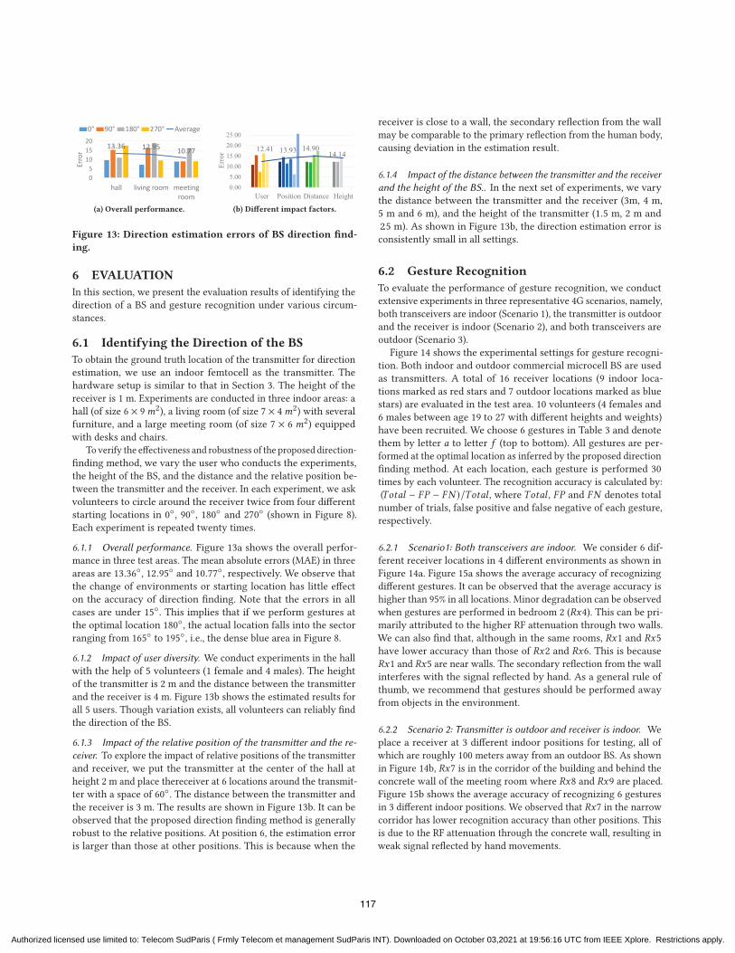
13.36 12.95 10.77
05
101520
hall living room meetingroom
Erro
r
0° 90° 180° 270° Average
(a) Overall performance.
12.41 13.93 14.90 14.14
0.005.00
10.0015.0020.0025.00
User Position Distance Height
Erro
r(b) Different impact factors.
Figure 13: Direction estimation errors of BS direction find-
ing.
6 EVALUATION
In this section, we present the evaluation results of identifying the
direction of a BS and gesture recognition under various circum-
stances.
6.1 Identifying the Direction of the BS
To obtain the ground truth location of the transmitter for direction
estimation, we use an indoor femtocell as the transmitter. The
hardware setup is similar to that in Section 3. The height of the
receiver is 1 m. Experiments are conducted in three indoor areas: a
hall (of size 6 × 9𝑚2), a living room (of size 7 × 4𝑚2) with severalfurniture, and a large meeting room (of size 7 × 6 𝑚2) equippedwith desks and chairs.
To verify the effectiveness and robustness of the proposed direction-
finding method, we vary the user who conducts the experiments,
the height of the BS, and the distance and the relative position be-
tween the transmitter and the receiver. In each experiment, we ask
volunteers to circle around the receiver twice from four different
starting locations in 0◦, 90◦, 180◦ and 270◦ (shown in Figure 8).
Each experiment is repeated twenty times.
6.1.1 Overall performance. Figure 13a shows the overall perfor-
mance in three test areas. The mean absolute errors (MAE) in three
areas are 13.36◦, 12.95◦ and 10.77◦, respectively. We observe thatthe change of environments or starting location has little effect
on the accuracy of direction finding. Note that the errors in all
cases are under 15◦. This implies that if we perform gestures at
the optimal location 180◦, the actual location falls into the sector
ranging from 165◦ to 195◦, i.e., the dense blue area in Figure 8.
6.1.2 Impact of user diversity. We conduct experiments in the hall
with the help of 5 volunteers (1 female and 4 males). The height
of the transmitter is 2 m and the distance between the transmitter
and the receiver is 4 m. Figure 13b shows the estimated results for
all 5 users. Though variation exists, all volunteers can reliably find
the direction of the BS.
6.1.3 Impact of the relative position of the transmitter and the re-
ceiver. To explore the impact of relative positions of the transmitter
and receiver, we put the transmitter at the center of the hall at
height 2 m and place thereceiver at 6 locations around the transmit-
ter with a space of 60◦. The distance between the transmitter and
the receiver is 3 m. The results are shown in Figure 13b. It can be
observed that the proposed direction finding method is generally
robust to the relative positions. At position 6, the estimation error
is larger than those at other positions. This is because when the
receiver is close to a wall, the secondary reflection from the wall
may be comparable to the primary reflection from the human body,
causing deviation in the estimation result.
6.1.4 Impact of the distance between the transmitter and the receiver
and the height of the BS.. In the next set of experiments, we vary
the distance between the transmitter and the receiver (3m, 4 m,
5 m and 6 m), and the height of the transmitter (1.5 m, 2 m and2.5 m). As shown in Figure 13b, the direction estimation error isconsistently small in all settings.
6.2 Gesture Recognition
To evaluate the performance of gesture recognition, we conduct
extensive experiments in three representative 4G scenarios, namely,
both transceivers are indoor (Scenario 1), the transmitter is outdoor
and the receiver is indoor (Scenario 2), and both transceivers are
outdoor (Scenario 3).
Figure 14 shows the experimental settings for gesture recogni-
tion. Both indoor and outdoor commercial microcell BS are used
as transmitters. A total of 16 receiver locations (9 indoor loca-
tions marked as red stars and 7 outdoor locations marked as blue
stars) are evaluated in the test area. 10 volunteers (4 females and
6 males between age 19 to 27 with different heights and weights)
have been recruited. We choose 6 gestures in Table 3 and denote
them by letter 𝑎 to letter 𝑓 (top to bottom). All gestures are per-formed at the optimal location as inferred by the proposed direction
finding method. At each location, each gesture is performed 30
times by each volunteer. The recognition accuracy is calculated by:
(𝑇𝑜𝑡𝑎𝑙 − 𝐹𝑃 − 𝐹𝑁 )/𝑇𝑜𝑡𝑎𝑙 , where 𝑇𝑜𝑡𝑎𝑙 , 𝐹𝑃 and 𝐹𝑁 denotes totalnumber of trials, false positive and false negative of each gesture,
respectively.
6.2.1 Scenario1: Both transceivers are indoor. We consider 6 dif-
ferent receiver locations in 4 different environments as shown in
Figure 14a. Figure 15a shows the average accuracy of recognizing
different gestures. It can be observed that the average accuracy is
higher than 95% in all locations. Minor degradation can be observed
when gestures are performed in bedroom 2 (𝑅𝑥4). This can be pri-marily attributed to the higher RF attenuation through two walls.
We can also find that, although in the same rooms, 𝑅𝑥1 and 𝑅𝑥5have lower accuracy than those of 𝑅𝑥2 and 𝑅𝑥6. This is because𝑅𝑥1 and 𝑅𝑥5 are near walls. The secondary reflection from the wallinterferes with the signal reflected by hand. As a general rule of
thumb, we recommend that gestures should be performed away
from objects in the environment.
6.2.2 Scenario 2: Transmitter is outdoor and receiver is indoor. We
place a receiver at 3 different indoor positions for testing, all of
which are roughly 100 meters away from an outdoor BS. As shown
in Figure 14b, 𝑅𝑥7 is in the corridor of the building and behind theconcrete wall of the meeting room where 𝑅𝑥8 and 𝑅𝑥9 are placed.Figure 15b shows the average accuracy of recognizing 6 gestures
in 3 different indoor positions. We observed that 𝑅𝑥7 in the narrowcorridor has lower recognition accuracy than other positions. This
is due to the RF attenuation through the concrete wall, resulting in
weak signal reflected by hand movements.
117
Authorized licensed use limited to: Telecom SudParis ( Frmly Telecom et management SudParis INT). Downloaded on October 03,2021 at 19:56:16 UTC from IEEE Xplore. Restrictions apply.
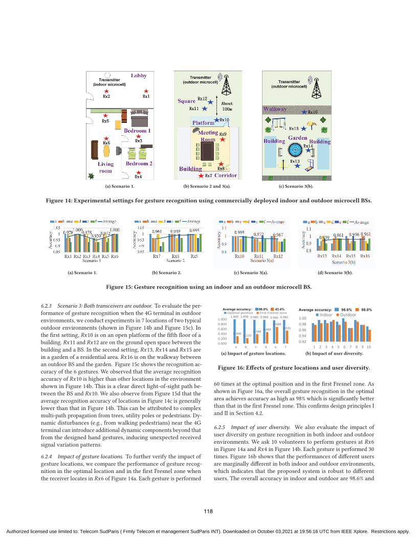
(a) Scenario 1. (b) Scenario 2 and 3(a). (c) Scenario 3(b).
Figure 14: Experimental settings for gesture recognition using commercially deployed indoor and outdoor microcell BSs.
(a) Scenario 1. (b) Scenario 2. (c) Scenario 3(a). (d) Scenario 3(b).
Figure 15: Gesture recognition using an indoor and an outdoor microcell BS.
6.2.3 Scenario 3: Both transceivers are outdoor. To evaluate the per-
formance of gesture recognition when the 4G terminal in outdoor
environments, we conduct experiments in 7 locations of two typical
outdoor environments (shown in Figure 14b and Figure 15c). In
the first setting, 𝑅𝑥10 is on an open platform of the fifth floor of abuilding. 𝑅𝑥11 and 𝑅𝑥12 are on the ground open space between thebuilding and a BS. In the second setting, 𝑅𝑥13, 𝑅𝑥14 and 𝑅𝑥15 arein a garden of a residential area. 𝑅𝑥16 is on the walkway betweenan outdoor BS and the garden. Figure 15c shows the recognition ac-
curacy of the 6 gestures. We observed that the average recognition
accuracy of 𝑅𝑥10 is higher than other locations in the environmentshown in Figure 14b. This is a clear direct light-of-sight path be-
tween the BS and 𝑅𝑥10. We also observe from Figure 15d that theaverage recognition accuracy of locations in Figure 14c is generally
lower than that in Figure 14b. This can be attributed to complex
multi-path propagation from trees, utility poles or pedestrians. Dy-
namic disturbances (e.g., from walking pedestrians) near the 4G
terminal can introduce additional dynamic components beyond that
from the designed hand gestures, inducing unexpected received
signal variation patterns.
6.2.4 Impact of gesture locations. To further verify the impact of
gesture locations, we compare the performance of gesture recog-
nition in the optimal location and in the first Fresnel zone when
the receiver locates in 𝑅𝑥6 of Figure 14a. Each gesture is performed
1.000 1.000 0.980 0.980 0.960 0.980
0.300 0.220 0.388 0.469
0.688 0.531
0.0000.2000.4000.6000.8001.000
a b c d e f
Optimal position First Fresnel zoneAverage accuracy: 98.0% 43.4%
(a) Impact of gesture locations.
0.920.940.960.981.00
1 2 3 4 5 6 7 8 9 10
Average accuracy: 98.6% 98.0%Indoor Outdoor
(b) Impact of user diversity.
Figure 16: Effects of gesture locations and user diversity.
60 times at the optimal position and in the first Fresnel zone. As
shown in Figure 16a, the overall gesture recognition in the optimal
area achieves accuracy as high as 98% which is significantly better
than that in the first Fresnel zone. This confirms design principles I
and II in Section 4.2.
6.2.5 Impact of user diversity. We also evaluate the impact of
user diversity on gesture recognition in both indoor and outdoor
environments. We ask 10 volunteers to perform gestures at 𝑅𝑥6in Figure 14a and 𝑅𝑥4 in Figure 14b. Each gesture is performed 30times. Figure 16b shows that the performances of different users
are marginally different in both indoor and outdoor environments,
which indicates that the proposed system is robust to different
users. The overall accuracy in indoor and outdoor are 98.6% and
118
Authorized licensed use limited to: Telecom SudParis ( Frmly Telecom et management SudParis INT). Downloaded on October 03,2021 at 19:56:16 UTC from IEEE Xplore. Restrictions apply.
98.0%, respectively. Since the indoor location is closer to the BS
and experiences less interference, the recognition accuracy at the
locations is slightly higher than that of the outdoor locations.
In addition to the above experiments, we also tested the proposed
system to control a TV remotely for one day in a smart home
with the indoor microcell BS (see https://youtu.be/e_OiQVkDExk).
Similar accuracy has been observed throughout the day.
6.3 Discussion
6.3.1 Limitations. Since the model assumes a single dynamic com-
ponent, the recognition accuracy of the system decreases when
there are multiple moving objects near the terminal. False negatives
and false positives indeed exist in practice. A false negative (or miss
reporting) happens when the execution of a gesture significantly
deviates from the specification. For instance, when the range of mo-
tion is much smaller than 𝑑 or the actual orientation of the gestureis far from the optimal one, the resulting patterns may be dissimilar
to the known profiles. A false positive (or false alarm) may occur
in the presence of movements of the face, hand or other parts of
the human body, such as raising hands, moving the body forth
and back, or other moving objects in the surroundings. These null
movements may generate patterns similar to the designed patterns.
Such errors can be mitigated by considering the duration of the
gestures.
6.3.2 Applicability to other wireless systems. The proposed CSI
ratio calculation and gesture recognition solution are applicable to
other wireless systems as long as OFDM and MIMO are utilized in
the physical layer. Examples include WiFi 802.11g and above, 5G
cellular networks. The design principles derived from Fresnel zone
analysis are expected to provide insights to the design of other RF
sensing solutions.
7 RELATEDWORK
7.1 Non-RF based gesture recognition.
Non-RF based techniques have been widely used in gesture recog-
nition, including wearable devices [9, 31] , computer vision [13, 18]
and sound waves [14, 22, 28]. Wearable device based methods use
dedicated sensors worn by users’ hands for gesture recognition. For
example, FDSVM [31] uses a wearable 3-dimensional accelerometer
to recognize 12 gestures with high accuracy. Wearable ring-type [9]
or watch-type [25] sensors have been used for recognizing vari-
ous finger or hand gestures for text input or appliances control.
However, these methods all require users to wear physical sensors,
which is inconvenient. Computer vision based systems (such as Mi-
crosoft Kinectand Leapmotion [13]) use cameras or infrared sensors
to reconstruct the depth information from images. Although these
approaches do not require a user to wear any sensors, these still rely
on dedicated hardware and cannot work well in poor lighting con-
ditions. Acoustic based approaches use speakers and microphones
to gather echoes of the hand to recognize gestures [22]. LLAP [28]
uses phase change of the sound signal for motion sensing. Finge-
rIO [14] uses OFDM modulated sound signals for centimeter-level
finger tracking. While promising, the sonar based systems only
have limited sensing range and have risk of privacy leak due to the
fact that devices record sound waves while working.
7.2 RF-based gesture recognition.
Recently, RF-based gesture recognition has been actively explored.
For instance, SideSwipe [39] and AllSee [10] use TV and cellular
transmissions to recognize hand, arm, and leg gestures, respec-
tively. WiTrack [3] also uses custom radar transmissions to detect
pointing gestures. Gestures can also be sensed with the Channel
State Information (CSI) in an RF communication system like WiFi.
WiKey [4] andMudra [37] extract unique patterns in the time-series
of CSI values of WiFi signals to identify different finger gestures.
More recently, WiMu [24] applies the Short Time Fourier Trans-
form (STFT) on denoised CSI stream and generates virtual samples
to enable multi-user gesture recognition. Most of them are learning-
based approaches. They rely on distinguishable feature patterns and
use machine learning methods to classify different gestures. How-
ever, trained classifiers may not work properly when the system
setting changes. Besides, these works fail to consider that the varia-
tions of received CSI signals are highly dependent on the locations
and orientations of gestures. To overcome these problems, Widar
3.0 [40] derives and estimates the velocity profiles of gestures at
the signal level and attempts to construct a consistent signal profile
independent of location and orientation. However, it requires one
transmitter and multiple receivers placed orthogonally around the
users to record gestures from different views, which is usually not
possible in 4G/5G scenes.
7.3 4G/5G-based sensing.
Benefiting from the wide radio signal coverage of 4G and 5G signals,
it is attractive to leverage these ubiquitous signals for sensing [6].
With the CSI extracted from CRS of LTE signals, it is possible
to localize the device with an error of 43 m Root Mean Square
(RMS) for outdoor scenes [11] and with an error of 1 m by using
fingerprinting-based approaches for indoor scenarios [19, 20]. Sys-
tem in [7] investigates the possibility to use LTE signals for crowd
density estimation by extracting statistical features of Reference
Signal Received Power (RSRP) in LTE. Works in [21]show the capa-
bility of LTE signals for motion detection. Besides 4G-based sensing,
a few 5G prototype systems are proposed for preliminary human
sensing, such as crowd-size detection [8] and walking speed recog-
nition [8]. However, no gesture recognition systems using 4G/5G
signals are reported before. In fact, existing studies on 4G/5G-based
sensing mainly focus on coarse-grained activity, and there is no
work exploring small scale movements like hand gestures.
8 CONCLUSION
In this paper, we empirically found that the repeatability and dis-
cernibility of gestures in LTE-based gesture recognition systems
are location-dependent and orientation-dependent. By analyzing
the Fresnel zone characteristics around a 4G terminal, we provided
guiding principles for training-free robust gesture designs and de-
veloped a robust gesture interaction system. Extensive experiments
showed that the proposed system can achieve high accuracy in
estimating the direction of BSs and gesture recognition in various
environments and configurations for different users.
119
Authorized licensed use limited to: Telecom SudParis ( Frmly Telecom et management SudParis INT). Downloaded on October 03,2021 at 19:56:16 UTC from IEEE Xplore. Restrictions apply.
ACKNOWLEDGEMENTS
This research is supported by National Key Research and Devel-
opment Plan under Grant No.2016YFB1001200, EU CHIST-ERA
RadioSense Project, and Peking University Information Technology
Institute (Tianjin Binhai).
REFERENCES[1] 2019. LTE; Evolved Universal Terrestrial Radio Access (E-UTRA); Physical chan-nels and modulation (3GPP TS 36.211 version 15.6.0 Release 15).
[2] Heba Abdelnasser, Khaled Harras, and Moustafa Youssef. 2018. A UbiquitousWiFi-based Fine-Grained Gesture Recognition System. IEEE Transactions onMobile Computing (2018), 1–1.
[3] Fadel Adib, Zach Kabelac, Dina Katabi, and Robert C. Miller. 2014. 3D Trackingvia Body Radio Reflections. In 11th USENIX Symposium on Networked SystemsDesign and Implementation (NSDI 14). Seattle, WA, 317–329.
[4] Kamran Ali, Alex X. Liu, Wei Wang, and Muhammad Shahzad. 2015. KeystrokeRecognition Using WiFi Signals. In Proceedings of the 21st Annual InternationalConference on Mobile Computing and Networking (Paris, France) (MobiCom ’15).90–102.
[5] Imee Ristika Rahmi Barani and Kin-Lu Wong. 2018. Integrated Inverted-F andOpen-Slot Antennas in theMetal-Framed Smartphone for2×2LTE LB and4×4LTEM/HB MIMO Operations. IEEE Transactions on Antennas and Propagation 66, 10(2018), 5004–5012.
[6] Weiyan Chen, Kai Niu, Dan Wu, Deng Zhao, Leye Wang, and Daqing Zhang.2019. A contactless gesture interaction system using LTE (4G) signals. In AdjunctProceedings of the 2019 ACM International Joint Conference on Pervasive andUbiquitous Computing and Proceedings of the 2019 ACM International Symposiumon Wearable Computers. 260–263.
[7] Simone Di Domenico, Mauro De Sanctis, Ernestina Cianca, Paolo Colucci, andGiuseppe Bianchi. 2017. LTE-based passive device-free crowd density estimation.In 2017 IEEE International Conference on Communications (ICC). 1–6.
[8] Bahareh Gholampooryazdi, Isha Singh, and Stephan Sigg. 2017. 5G UbiquitousSensing: Passive Environmental Perception in Cellular Systems. In 2017 IEEE 86thVehicular Technology Conference (VTC-Fall). 1–6.
[9] Lei Jing, Yinghui Zhou, Zixue Cheng, and Tongjun Huang. 2012. Magic Ring: AFinger-Worn Device for Multiple Appliances Control Using Static Finger Gestures.Sensors 12, 5 (2012), 5775–5790.
[10] Bryce Kellogg, Vamsi Talla, and Shyamnath Gollakota. 2014. Bringing GestureRecognition to All Devices. In 11th USENIX Symposium on Networked SystemsDesign and Implementation (NSDI 14). Seattle, WA, 303–316.
[11] Fabian Knutti, Mischa Sabathy, Marco Driusso, Heinz Mathis, and Chris Marshall.2015. Positioning using LTE signals. In Proceedings of Navigation Conference inEurope. 1–8.
[12] Xiang Li, Daqing Zhang, Jie Xiong, Yue Zhang, Shengjie Li, Yasha Wang, andHong Mei. 2018. Training-Free Human Vitality Monitoring Using CommodityWi-Fi Devices. Proceedings of the ACM on Interactive, Mobile, Wearable andUbiquitous Technologies 2, 3 (2018), 121.
[13] Giulio Marin, Fabio Dominio, and Pietro Zanuttigh. 2014. Hand gesture recogni-tion with leap motion and kinect devices. In 2014 IEEE International Conferenceon Image Processing (ICIP). 1565–1569.
[14] Rajalakshmi Nandakumar, Vikram Iyer, Desney Tan, and Shyamnath Gollakota.2016. FingerIO: Using Active Sonar for Fine-Grained Finger Tracking. In Pro-ceedings of the 2016 CHI Conference on Human Factors in Computing Systems (SanJose, California, USA) (CHI ’16). 1515–1525.
[15] Kai Niu, Fusang Zhang, Yuhang Jiang, Jie Xiong, Qin Lv, Youwei Zeng, andDaqing Zhang. 2019. WiMorse: A Contactless Morse Code Text Input Systemusing Ambient WiFi Signals. IEEE Internet of Things Journal (2019), 1–1.
[16] Kai Niu, Fusang Zhang, Jie Xiong, Xiang Li, Enze Yi, and Daqing Zhang. 2018.Boosting Fine-grained Activity Sensing by Embracing Wireless Multipath Ef-fects. In Proceedings of the 14th International Conference on Emerging NetworkingEXperiments and Technologies (Heraklion, Greece) (CoNEXT ’18). 139–151.
[17] Junbum Park and Sung Ho Cho. 2016. IR-UWB Radar Sensor for Human Ges-ture Recognition by Using Machine Learning. In 2016 IEEE 18th InternationalConference on High Performance Computing and Communications; IEEE 14th In-ternational Conference on Smart City; IEEE 2nd International Conference on DataScience and Systems (HPCC/SmartCity/DSS). 1246–1249.
[18] Orasa Patsadu, Chakarida Nukoolkit, and Bunthit Watanapa. 2012. Humangesture recognition using Kinect camera. In 2012 Ninth International Conferenceon Computer Science and Software Engineering (JCSSE). 28–32.
[19] Giovanni Pecoraro, Simone Di Domenico, Ernestina Cianca, and Mauro De Sanc-tis. 2017. LTE signal fingerprinting localization based on CSI. In 2017 IEEE13th International Conference on Wireless and Mobile Computing, Networking andCommunications (WiMob). 1–8.
[20] Giovanni Pecoraro, Simone Di Domenico, Ernestina Cianca, and Mauro De Sanc-tis. 2018. CSI-based fingerprinting for indoor localization using LTE Signals.
EURASIP Journal on Advances in Signal Processing 2018, 1 (27 Jul 2018), 49.[21] Raja Syamsul Azmir Raja Abdullah, Asem Ahmad Salah, and Nur Emileen Ab-
dul Rashid. 2015. Moving target detection by using new LTE-based passive radar.Progress In Electromagnetics Research 63 (2015), 145–160.
[22] Ke Sun, Ting Zhao, Wei Wang, and Lei Xie. 2018. VSkin: Sensing Touch Gestureson Surfaces of Mobile Devices Using Acoustic Signals. In Proceedings of the 24thAnnual International Conference onMobile Computing and Networking (NewDelhi,India) (MobiCom ’18). 591–605.
[23] Michael Van den Bergh and Luc Van Gool. 2011. Combining RGB and ToF camerasfor real-time 3D hand gesture interaction. In 2011 IEEE Workshop on Applicationsof Computer Vision (WACV). 66–72.
[24] Raghav H. Venkatnarayan, Griffin Page, and Muhammad Shahzad. 2018. Multi-User Gesture Recognition Using WiFi. In Proceedings of the 16th Annual Interna-tional Conference on Mobile Systems, Applications, and Services (Munich, Germany)(MobiSys ’18). 401–413.
[25] Tran Huy Vu, Archan Misra, Quentin Roy, Kenny Choo Tsu Wei, and YoungkiLee. 2018. Smartwatch-based early gesture detection 8 trajectory tracking forinteractive gesture-driven applications. Proceedings of the ACM on Interactive,Mobile, Wearable and Ubiquitous Technologies 2, 1 (2018), 39.
[26] Hao Wang, Daqing Zhang, Junyi Ma, Yasha Wang, Yuxiang Wang, Dan Wu, TaoGu, and Bing Xie. 2016. Human Respiration Detection with Commodity WifiDevices: Do User Location and Body Orientation Matter?. In Proceedings of the2016 ACM International Joint Conference on Pervasive and Ubiquitous Computing(Heidelberg, Germany) (UbiComp ’16). 25–36.
[27] Wei Wang, Alex X. Liu, Muhammad Shahzad, Kang Ling, and Sanglu Lu. 2015.Understanding and Modeling of WiFi Signal Based Human Activity Recognition.In Proceedings of the 21st Annual International Conference on Mobile Computingand Networking (Paris, France) (MobiCom ’15). 65–76.
[28] Wei Wang, Alex X. Liu, and Ke Sun. 2016. Device-free Gesture Tracking UsingAcoustic Signals. In Proceedings of the 22Nd Annual International Conference onMobile Computing and Networking (New York City, New York) (MobiCom ’16).82–94.
[29] Dan Wu, Daqing Zhang, Chenren Xu, Hao Wang, and Xiang Li. 2017. Device-free WiFi human sensing: From pattern-based to model-based approaches. IEEECommunications Magazine 55, 10 (2017), 91–97.
[30] Dan Wu, Daqing Zhang, Chenren Xu, Yasha Wang, and Hao Wang. 2016. WiDir:Walking Direction Estimation Using Wireless Signals. In Proceedings of the 2016ACM International Joint Conference on Pervasive and Ubiquitous Computing (Hei-delberg, Germany) (UbiComp ’16). 351–362.
[31] Jiahui Wu, Gang Pan, Daqing Zhang, Guande Qi, and Shijian Li. 2009. GestureRecognition with a 3-D Accelerometer. In Ubiquitous Intelligence and Computing,Daqing Zhang, Marius Portmann, Ah-Hwee Tan, and Jadwiga Indulska (Eds.).Springer Berlin Heidelberg, Berlin, Heidelberg, 25–38.
[32] Yaxiong Xie, Zhenjiang Li, and Mo Li. 2019. Precise Power Delay Profilingwith Commodity Wi-Fi. IEEE Transactions on Mobile Computing 18, 6 (2019),1342–1355.
[33] Youwei Zeng, Dan Wu, Jie Xiong, Enze Yi, Ruiyang Gao, and Daqing Zhang. 2019.FarSense: Pushing the Range Limit of WiFi-based Respiration Sensing with CSIRatio of Two Antennas. Proceedings of the ACM on Interactive, Mobile, Wearableand Ubiquitous Technologies 3, 3 (2019), 121.
[34] Daqing Zhang, Hao Wang, and Dan Wu. 2017. Toward Centimeter-Scale HumanActivity Sensing with Wi-Fi Signals. Computer 50, 1 (2017), 48–57.
[35] Fusang Zhang, Kai Niu, Jie Xiong, Beihong Jin, Tao Gu, Yuhang Jiang, and DaqingZhang. 2019. Towards a Diffraction-based Sensing Approach on Human ActivityRecognition. Proc. ACM Interact. Mob. Wearable Ubiquitous Technol. 3, 1, Article33 (March 2019), 25 pages.
[36] Fusang Zhang, Daqing Zhang, Jie Xiong, Hao Wang, Kai Niu, Beihong Jin, andYuxiang Wang. 2018. From fresnel diffraction model to fine-grained humanrespiration sensing with commodity wi-fi devices. Proceedings of the ACM onInteractive, Mobile, Wearable and Ubiquitous Technologies 2, 1 (2018), 53.
[37] Ouyang Zhang and Kannan Srinivasan. 2016. Mudra: User-friendly Fine-grainedGesture Recognition Using WiFi Signals. In Proceedings of the 12th Internationalon Conference on Emerging Networking EXperiments and Technologies (Irvine,California, USA) (CoNEXT ’16). 83–96.
[38] Zhenyuan Zhang, Zengshan Tian, and Mu Zhou. 2018. Latern: Dynamic Con-tinuous Hand Gesture Recognition Using FMCW Radar Sensor. IEEE SensorsJournal 18, 8 (2018), 3278–3289.
[39] Chen Zhao, Ke-Yu Chen, Md Tanvir Islam Aumi, Shwetak Patel, and Matthew S.Reynolds. 2014. SideSwipe: Detecting In-air Gestures Around Mobile DevicesUsing Actual GSM Signal. In Proceedings of the 27th Annual ACM Symposiumon User Interface Software and Technology (Honolulu, Hawaii, USA) (UIST ’14).527–534.
[40] Yue Zheng, Yi Zhang, Kun Qian, Guidong Zhang, Yunhao Liu, Chenshu Wu, andZheng Yang. 2019. Zero-Effort Cross-Domain Gesture Recognition with Wi-Fi.In Proceedings of the 17th Annual International Conference on Mobile Systems,Applications, and Services (Seoul, Republic of Korea) (MobiSys ’19). 313–325.
120
Authorized licensed use limited to: Telecom SudParis ( Frmly Telecom et management SudParis INT). Downloaded on October 03,2021 at 19:56:16 UTC from IEEE Xplore. Restrictions apply.
Related Documents