Hindawi Publishing Corporation Mathematical Problems in Engineering Volume 2010, Article ID 627501, 18 pages doi:10.1155/2010/627501 Research Article Robust Design of S-Shaped Box Beams Subjected to Compressive Load A. Khakhali, 1 A. Darvizeh, 1 A. Masoumi, 2 N. Nariman-Zadeh, 1, 3 and A. Shiri 1 1 Department of Mechanical Engineering, Faculty of Engineering, The University of Guilan, P.O. Box 3756, Rasht 3756, Iran 2 Schools of Mechanical Engineering, Faculty of Engineering, University of Tehran, Tehran, Iran 3 Intelligent-Based Experimental Mechanics Center of Excellence, School of Mechanical Engineering, Faculty of Engineering, University of Tehran, Tehran, Iran Correspondence should be addressed to A. Khakhali, [email protected] Received 15 November 2009; Revised 27 April 2010; Accepted 28 June 2010 Academic Editor: Giuseppe Rega Copyright q 2010 A. Khakhali et al. This is an open access article distributed under the Creative Commons Attribution License, which permits unrestricted use, distribution, and reproduction in any medium, provided the original work is properly cited. In order to design the automotive components considering probabilistic uncertainties in the decision variables, it is desired to perform a robust design process. The peak crushing force of the energy absorber components is one of the important objectives of the design of such components. In this paper, at first, the peak crushing force of the S-shaped box beams, as a highly simplified model of front member of a vehicle body, is extracted mathematically. Using such obtained mathematical model and Monte Carlo simulation, genetic algorithm is then used for the robust design of the S-shaped box beams having probabilistic uncertainties in material and geometrical parameters. In this way the variance-per-mean ratio of the peak crushing force P max is considered as the objective function. It is shown that some interesting relationships as useful robust design principles involved in the performance of the S-shaped box beams can be discovered by the robust design of the obtained mathematical model. 1. Introduction Higher-speed transportation increases the probability of traffic accidents which in turn cause serious damages to passengers. Design of auxiliary metal structure or structural components capable of sustaining prescribed loads and absorbing crushing energies during plastic deformation has become a special task in design to ensure the occupant safety. Therefore the crash characteristic of energy absorbing component has received considerable attention over the past decades 1–7. As a highly simplified model of the front-side member of a

Welcome message from author
This document is posted to help you gain knowledge. Please leave a comment to let me know what you think about it! Share it to your friends and learn new things together.
Transcript
Hindawi Publishing CorporationMathematical Problems in EngineeringVolume 2010, Article ID 627501, 18 pagesdoi:10.1155/2010/627501
Research ArticleRobust Design of S-Shaped Box Beams Subjectedto Compressive Load
A. Khakhali,1 A. Darvizeh,1 A. Masoumi,2 N. Nariman-Zadeh,1, 3
and A. Shiri1
1 Department of Mechanical Engineering, Faculty of Engineering, The University of Guilan,P.O. Box 3756, Rasht 3756, Iran
2 Schools of Mechanical Engineering, Faculty of Engineering, University of Tehran, Tehran, Iran3 Intelligent-Based Experimental Mechanics Center of Excellence, School of Mechanical Engineering,Faculty of Engineering, University of Tehran, Tehran, Iran
Correspondence should be addressed to A. Khakhali, [email protected]
Received 15 November 2009; Revised 27 April 2010; Accepted 28 June 2010
Academic Editor: Giuseppe Rega
Copyright q 2010 A. Khakhali et al. This is an open access article distributed under the CreativeCommons Attribution License, which permits unrestricted use, distribution, and reproduction inany medium, provided the original work is properly cited.
In order to design the automotive components considering probabilistic uncertainties in thedecision variables, it is desired to perform a robust design process. The peak crushing force of theenergy absorber components is one of the important objectives of the design of such components.In this paper, at first, the peak crushing force of the S-shaped box beams, as a highly simplifiedmodel of front member of a vehicle body, is extracted mathematically. Using such obtainedmathematical model and Monte Carlo simulation, genetic algorithm is then used for the robustdesign of the S-shaped box beams having probabilistic uncertainties in material and geometricalparameters. In this way the variance-per-mean ratio of the peak crushing force (Pmax) is consideredas the objective function. It is shown that some interesting relationships as useful robust designprinciples involved in the performance of the S-shaped box beams can be discovered by the robustdesign of the obtained mathematical model.
1. Introduction
Higher-speed transportation increases the probability of traffic accidents which in turn causeserious damages to passengers. Design of auxiliary metal structure or structural componentscapable of sustaining prescribed loads and absorbing crushing energies during plasticdeformation has become a special task in design to ensure the occupant safety. Thereforethe crash characteristic of energy absorbing component has received considerable attentionover the past decades [1–7]. As a highly simplified model of the front-side member of a
2 Mathematical Problems in Engineering
vehicle body, which plays an important role in absorbing energy during collision, variousinvestigators in previous works [8–14] have studied the crushing behavior of the S-shapedstructures.
In real engineering practices, there exist various sources of uncertainty which haveto be compensated through optimal robust design approach [15–17]. Those uncertaintiesinclude model parameter variations due to environmental conditions, incomplete knowledgeof parameters including material and geometry variables, age, and so forth [18–20]. Inconventional optimum system design, uncertainties are not addressed and the optimizationprocess is accomplished deterministically. In fact, it has been shown that optimizationwithout considering uncertainty generally leads to nonoptimal and potentially high-risk solution [15, 21–25]. Therefore, it is very desirable to find a robust design whoseperformance variation in the presence of uncertainties is not high. Generally, thereexist two approaches addressing the stochastic robustness issue, namely, robust designoptimization (RDO) and reliability-based design optimization (RBDO) [26]. Both approachesrepresent nondeterministic optimization formulations in which the probabilistic uncertaintyis incorporated into the robust optimal design process. Therefore, the propagation of aprior knowledge regarding the uncertain parameters through the system provides someprobabilistic metrics such as random variable and random process [21]. In RDO approach,the robust performance is required to be less sensitive to the random variation induced byuncertain parameters so that the performance degradation from ideal deterministic behavioris minimized. In RBDO approach, some evaluated reliability metrics subjected to probabilisticconstraints are satisfied so that the violation of design requirement is minimized. Regardlessof the choice of any of these two approaches, the objective function (e.g., peak crushingforce) and the constraints of the optimal design should be evaluated reflecting the effectof probabilistic nature of uncertain parameters in the performance of the system. With theaid of ever-increasing computational power, there have been a great amount of researchactivities in the field of robust analysis and design devoted to the use of Monte Carlosimulation [21, 22]. In fact, MCS has also been used to verify the results of other methodsin RDO or RBDO problems when sufficient number of sampling is adopted. In the MonteCarlo simulation (MCS) method, random samples are generated assuming pre-definedprobabilistic distributions for uncertain parameters.
Basically, the optimization process is defined as finding a set of values for a vectorof design variables so that it leads to an optimum value of an objective or cost function.In such single-objective optimization problems, there may or may not exist some constraintfunctions on the design variables and they are, respectively, referred to as constrained orunconstrained optimization problems. There are many calculus-based methods includinggradient approaches to search for mostly local optimum solutions and these are welldocumented [27, 28]. However, some basic difficulties in the gradient methods such astheir strong dependence on the initial guess can cause them to find a local optimumrather than a global one. This has led to other heuristic optimization methods, particularlyGenetic Algorithms (GAs) that are being used extensively during the last decade [29, 30].Such nature-inspired evolutionary algorithms differ from other traditional calculus-basedtechniques [31, 32]. The main difference is that GAs work with a population of candidatesolutions and not with a single solution in the search space. This helps significantly to avoidbeing trapped in local optima [33] as long as the diversity of the population is well preserved.
In this paper, peak crushing force of the S-shaped box beams is mathematicallymodeled. The obtained model is then used in a combined robust and reliability-based designapproach to find a reliable and robust design. In this way, to minimize the variation of
Mathematical Problems in Engineering 3
L
a bc
de
θ
lab
lcd
lef
R
D
C
tf
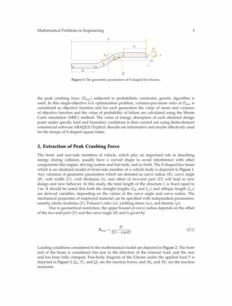
Figure 1: The geometric parameters of S-shaped box beams.
the peak crushing force (Pmax) subjected to probabilistic constraint, genetic algorithm isused. In this single-objective GA optimization problem, variance-per-mean ratio of Pmax isconsidered as objective function and for each generation the value of mean and varianceof objective function and the value of probability of failure are calculated using the MonteCarlo simulation (MSC) method. The value of energy absorption of each obtained designpoint under specific load and boundary conditions is then carried out using finite-elementcommercial software ABAQUS/Explicit. Results are informative and maybe effectively usedfor the design of S-shaped square tubes.
2. Extraction of Peak Crushing Force
The front- and rear-side members of vehicle, which play an important role in absorbingenergy during collision, usually have a curved shape to avoid interference with othercomponents like engine, driving system and fuel tank, and so forth. The S-shaped box beamwhich is an idealized model of front-side member of a vehicle body is depicted in Figure 1.Any variation of geometric parameters which are denoted as curve radius (R), curve angle(θ), web width (C), wall thickness (t), and offset of two-end part (D) will lead to newdesign and new behavior. In this study, the total length of the structure L is fixed equal to1 m. It should be noted that both the straight lengths (lab and lef) and oblique length (lcd)are derived variables, depending on the values of the curve angle and curve radius. Themechanical properties of employed material can be specified with independent parameters,namely, elastic modulus (E), Poisson’s ratio (υ), yielding stress (σ0), and density (ρ).
Due to geometrical restriction, the upper bound of curve radius depends on the offsetof the two-end part (D) and the curve angle (θ) and is given by
Rmax =D
2(1 − cos θ). (2.1)
Loading conditions considered in the mathematical model are depicted in Figure 2. The frontend of the beam is considered free just in the direction of the external load, and the rearend has been fully clamped. Free-body diagram of the S-beam under the applied load P isdepicted in Figure 3; Qa, Pf , and Qf are the reaction forces, and Ma and Mf are the reactionmoments.
4 Mathematical Problems in Engineering
P
Loaded end
Clamped end
Figure 2: Loading conditions considered in the mathematical model.
P
Ma
Qa
Pf
Mf
Qf
1 2
34 5
Figure 3: Free-body diagram of the S-beam under the applied load.
The equilibrium equations for the S-beam are expressed as follows:
Pf = P,
Qa = Qf = Q,(2.2)
Mf = −Ma − PD +QL. (2.3)
For determining unknown reactions, two additional equations are needed. Equations for thedeflection along direction y and the slope of beam at the point a can be used to solve thisindeterminate system. Using Castigliano’s theorem, these equations can be written as follows:
ya =∂U
∂Qa= 0, (2.4)
θa =∂U
∂Ma= 0, (2.5)
where U is the strain energy of the beam under the applied load P. For simplicity, in thisstudy, only the strain energy due to bending has been considered and formulated as follows:
U =∫Ms
2
2EIds, (2.6)
Mathematical Problems in Engineering 5
where, Ms is the cross-sectional bending moment along the beam. To determine Ms, the fivedifferent sections depicted in Figure 3 along the beam have been considered. The equation ofthe equilibrium of moment for these sections is expressed as follows For Section 1.
M1 =Ma −Qax1, (2.7)
where x1 is the distance from a along the first straight part ab.For Section 2,
M2 =Ma + PR(1 − cos θ1) −Qa(lab + R sin θ1), (2.8)
where θ1 denotes meridian coordinate system along the first curve part bc.For Section 3,
M3 =Ma + P(R(1 − cos θ) + x2 sin θ) −Qa((lab + R sin θ) + x2 cos θ), (2.9)
where x2 is the distance from c along the oblique part cd.For Section 4,
M4 =Ma + P[R(1 − cos θ) + lcd sin θ + R(cos(θ − θ2) − cos θ))
−Qa[(lab + R sin θ) + lcd cos θ + R(sin θ − sin(θ − θ2))],(2.10)
where θ2 denotes the meridian coordinate system along the second curve part de.For Section 5,
M5 = −Mf +Qfx3, (2.11)
where x3 is the distance from f along the second straight part ef. Substituting (2.6)–(2.11) and(2.3) in (2.4),
ya =∂U
∂Qa=
5∑i=1
∫Mi
EI
∂Mi
∂Qads
= − 1EI
(∫ lab0M1x1dx1 +
∫θ0M2(lab + R sin θ1)Rdθ1
+∫ lcd
0M3((lab + R sin θ) + x2 cos θ)dx2
+∫θ
0M4(lab + 2R sin θ + lcd cos θ − R sin(θ − θ2))Rdθ2
+∫ lef
0(M + PD −Q(L − x3))(L − x3)dx3
),
(2.12)
6 Mathematical Problems in Engineering
which can be evaluated as
fMa − gQa + hP = 0, (2.13)
where
f =lab
2
2+ R(labθ + R(1 − cos θ)) +
((lab + R sin θ)lcd +
lab2
2cos θ
)
+ R((lab + 2R sin θ + lcd cos θ)θ − R(1 − cos θ)) + Llef3 −
lef2
2,
g =lab
3
3+ R
(lab
2θ +R2
2(1 − cos 2θ) + 2labR(1 − cos θ)
)
+
((lab + R sin θ)2lcd +
lef3
3cos θ + 2(lab + R sin θ) cos θ
lcd2
2
)
+ R
((lab+2R sin θ+lcd cos θ)2θ+
R2
2(1 − cos 2θ)−2(lab+2R sin θ+lcd cos θ)R(1 − cos θ)
)
+ Llcd3 − lcd
2
2,
h = R2(lab(θ − sin θ) + R(1 − cos θ)) + R(1 − cos θ)(lab + R sin θ)lcd +lcd
3
6sin 2θ
+lcd
2
2((sin θ(lab + R sin θ)) + R cos θ(1 − cos θ))
+ (R(1 − 2 cos θ) + lcd sin θ)((lab + 2R sin θ) + lcd cos θ)Rθ − R3
4(1 − cos 2θ)
+ R2(lab + 2R sin θ + lcd cos θ) sin θ − R2(R(1 − 2 cos θ) + lcd sin θ)(1 − cos θ) +Dlef
2
2.
(2.14)
Similarly, substituting (2.6)–(2.11) and (2.3) in (2.5) gives
θa =∂U
∂Ma=
5∑i=1
∫Mi
EI
∂Mi
∂Mads
= − 1EI
(∫ lab0M1dx1 +
∫θ0M2Rdθ1 +
∫ lcd0M3dx2
+∫θ
0M4Rdθ2 +
∫ lef0(Ma + PD −Q(L − x))dx3
),
(2.15)
Mathematical Problems in Engineering 7
which can be evaluated as
f ′Ma − g ′Qa + h′P = 0, (2.16)
where
f ′ = lab + 2Rθ + lcd + lef ,
g ′ =lab
2
2+ R(labθ + R(1 − cos θ)) +
((lab + sin θ)lcd +
lcd2
2sin θ
)
+ ((lab + 2R sin θ + lcd cos θ)θ − (1 − cos θ)) +lef
2
2,
h′ = R2(θ − sin θ) + R(1 − cos θ)lcd +lcd
2
2cos θ + (R(1 − 2 cos θ) + lcd sin θ)θ + R sin θ +Dlef .
(2.17)
From (2.13) and (2.16), Qa and Ma can be obtained from
Qa = Ja × P, (2.18)
Ma = Ka × P, (2.19)
where
Ka =gh′ − g ′hg ′f − gf ′ , Ja =
fh′ − f ′hg ′f − gf ′ . (2.20)
Substituting values of Ma and Qa obtained from (2.18) and (2.19) in the (2.7)–(2.11), bendingmoment will be determined for any section along the beam. Similarly, the equilibriumequation of the axial force for sections shown in Figure 3 can be written as follows:
N1 = P, (2.21)
N2 = P cos θ1 +Qa sin θ1, (2.22)
N3 = P cos θ0 +Qa sin θ0, (2.23)
N4 = P cos θ2 +Qa sin θ2, (2.24)
8 Mathematical Problems in Engineering
10.80.60.40.20
Horizontal distance from front end of beam (mm)
R = 200 mmR = 350 mm
R = 500 mmS-beam layout
−0.05
−0.04−0.03−0.02−0.01
0
0.010.020.030.040.05
Sect
iona
lben
din
gm
omen
t(N
.m)
−0.2
−0.15
−0.1
−0.05
0
0.05
0.1
0.15
0.2
Ver
tica
ldes
ign
from
O(m
m)
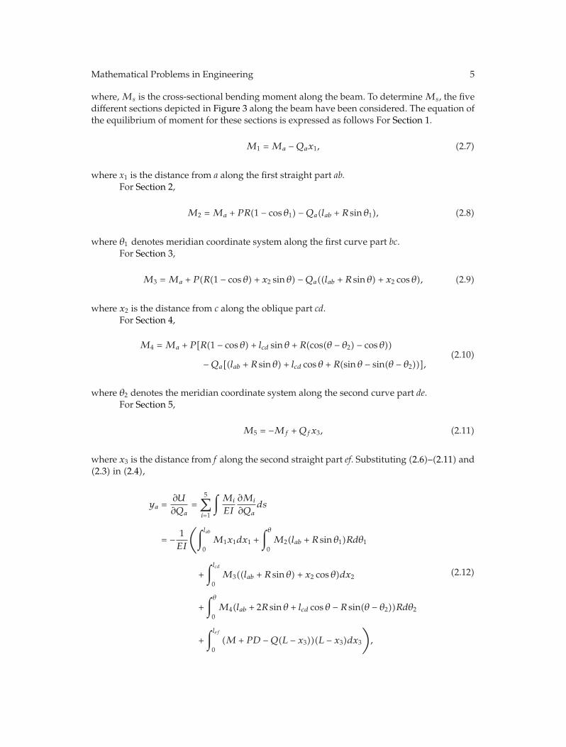
Figure 4: Cross sectional bending moment diagram for the S-shaped box beams with three different curveradii.
10.80.60.40.20
Horizontal distance from front end of beam (mm)
R = 200 mmR = 350 mmR = 500 mm
0.97
0.98
0.99
1
1.01
1.02
1.03
Sect
iona
laxi
alfo
rce(N
.m)
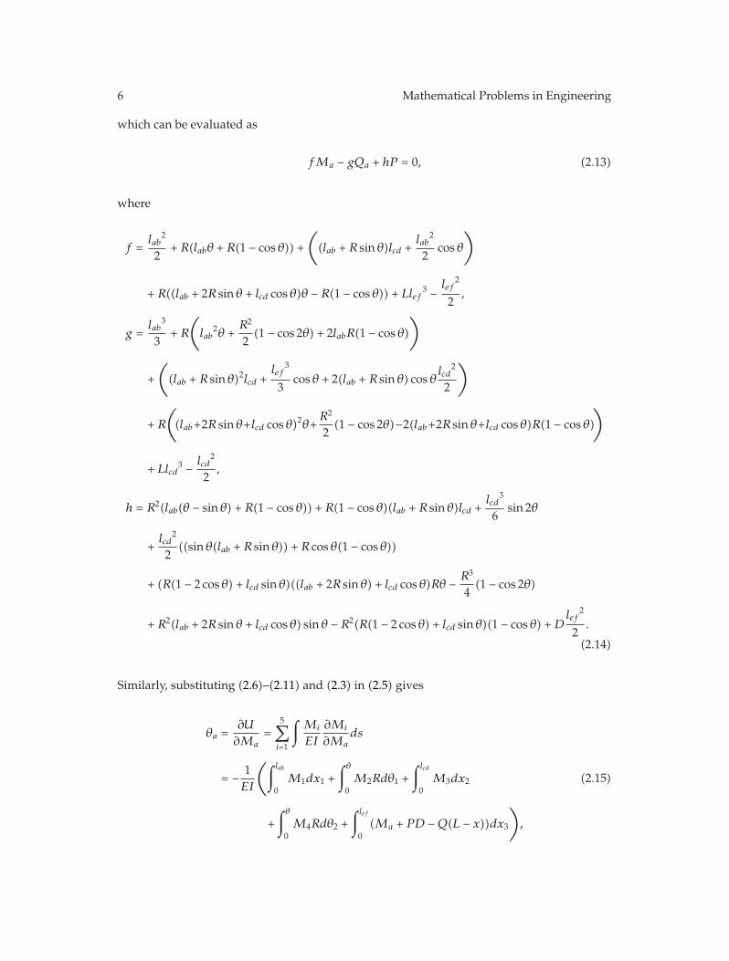
Figure 5: Cross sectional axial force diagram for the S-shaped box beams with three different curve radii.
N5 = P, (2.25)
where N1 to N5 are the cross-sectional axial forces of Sections 1 to 5. Figures 4 and 5 show thediagram of cross sectional bending moment and cross sectional axial force for the S-shapedbox beams with geometrical parameters: D = 150 mm, θ = 30◦, and curve radii R = 200, 350,and 500 mm, where P = 1 N.
The stress at the extreme fibers of all beam sections can be determined simply from,
σ =2MC
I+N
A, (2.26)
where I, A, and C are the inertia moment, area, and width of cross-section, respectively.Distribution of the stress σ along the beam is depicted in Figure 6. It is evident from thisfigure that the maximum stress locates on four places: two points at the curve parts and twopoints at the front- and rear-end of the beam. These locations are depicted with the points
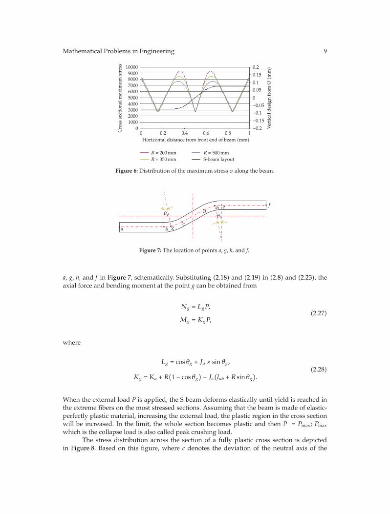
Mathematical Problems in Engineering 9
10.80.60.40.20Horizontal distance from front end of beam (mm)
R = 200 mmR = 350 mm
R = 500 mmS-beam layout
0100020003000400050006000700080009000
10000
Cro
ssse
ctio
nalm
axim
umst
ress
−0.2
−0.15
−0.1
−0.05
0
0.05
0.1
0.15
0.2
Ver
tica
ldes
ign
from
O(m
m)
Figure 6: Distribution of the maximum stress σ along the beam.
a b gc
dh e f
θg θh
Figure 7: The location of points a, g, h, and f.
a, g, h, and f in Figure 7, schematically. Substituting (2.18) and (2.19) in (2.8) and (2.23), theaxial force and bending moment at the point g can be obtained from
Ng = LgP,
Mg = KgP,(2.27)
where
Lg = cos θg + Ja × sin θg,
Kg = Ka + R(1 − cos θg
)− Ja(lab + R sin θg
).
(2.28)
When the external load P is applied, the S-beam deforms elastically until yield is reached inthe extreme fibers on the most stressed sections. Assuming that the beam is made of elastic-perfectly plastic material, increasing the external load, the plastic region in the cross sectionwill be increased. In the limit, the whole section becomes plastic and then P = Pmax; Pmax
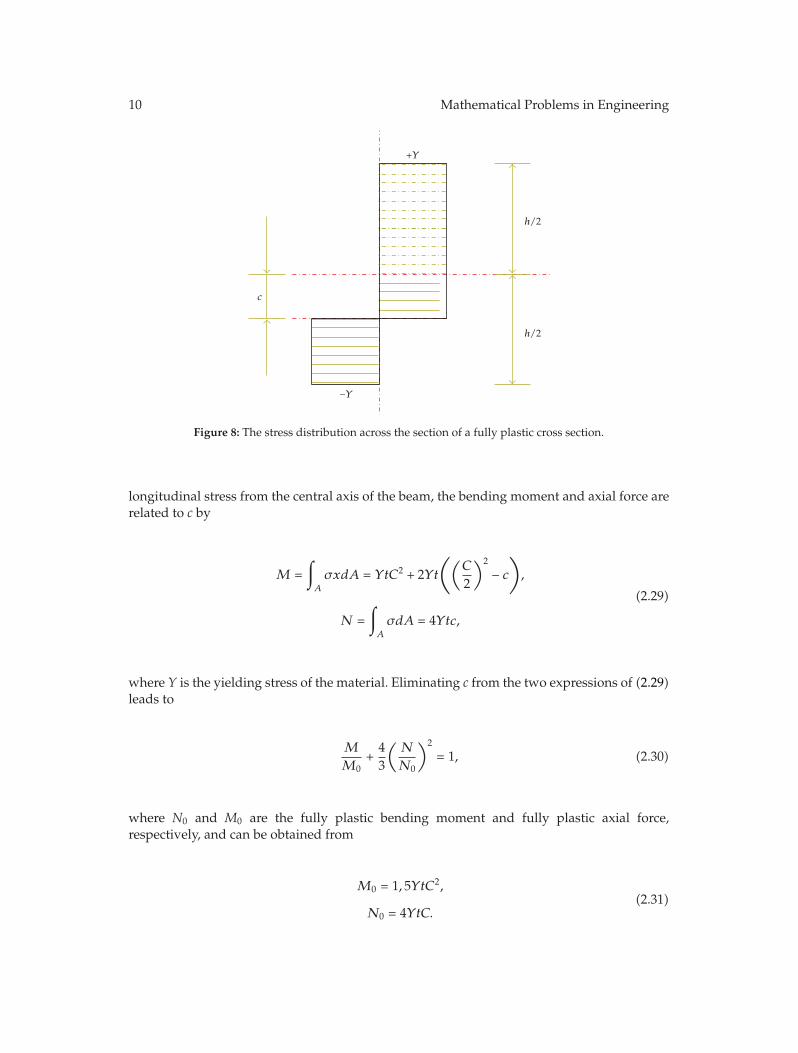
which is the collapse load is also called peak crushing load.The stress distribution across the section of a fully plastic cross section is depicted
in Figure 8. Based on this figure, where c denotes the deviation of the neutral axis of the
10 Mathematical Problems in Engineering
c
+Y
−Y
h/2
h/2
Figure 8: The stress distribution across the section of a fully plastic cross section.
longitudinal stress from the central axis of the beam, the bending moment and axial force arerelated to c by
M =∫A
σxdA = YtC2 + 2Yt
((C
2
)2
− c),
N =∫A
σdA = 4Ytc,
(2.29)
where Y is the yielding stress of the material. Eliminating c from the two expressions of (2.29)leads to
M
M0+
43
(N
N0
)2
= 1, (2.30)
where N0 and M0 are the fully plastic bending moment and fully plastic axial force,respectively, and can be obtained from
M0 = 1, 5YtC2,
N0 = 4YtC.(2.31)
Mathematical Problems in Engineering 11
Considering sections a and f depicted in Figure 7 as the most stressed sections andsubstituting (2.18) in (2.30), Pmax can be obtained from
Pmax,1 =4/3
(Ka/M0) + (4La/3N0). (2.32)
Otherwise, considering sections g and h as the most stressed sections and substituting (2.18)in (2.30), Pmax can be obtained from
Pmax,2 =4/3(
KgM0)+(4Lg/3N0
) . (2.33)
Therefore, the peak crushing force of S-shaped box beams can be obtained from
Pmax = min{Pmax,1, Pmax,2}. (2.34)
3. Stochastic Robust Analysis
In the robust design approach, it is desired to minimize the variability of a random processdue to the uncertain probabilistic parameters about a deterministic behavior. Therefore, theconventional robust optimization problem can be formulated as follows:
Minimize{μ[f(x,d,p)
], υ[f(x,d,p)
]},
x(L) ≤ x ≤ x(U),
d(L) ≤ d ≤ d(U),
(3.1)
where f(x,d,p) is the performance or the cost function, μ is the mean value, and υ is one ofthe dispersion measure operators such as variance (σ2), standard deviation (σ), or coefficientof variation (Cv = σ/ μ). In this study, x is the vector of design variables which are uncertain,d is the vector of deterministic design variables, and p is the vector of uncertain parameterswhich are not design variables.
In the reliability-based design approach, it is required to define some reliabilitymetrics via some inequality constraints. Let us consider a deterministic constraint of theform gi(x,d,p)≤ gi, where gi is the limiting value of the ith constraint. This constraint canbe transformed into a probabilistic constraint using the definition of a random process
Gi(x,d,p) ≡ gi − gi(x,d,p). (3.2)
The typical probability constraint is then represented as
Pif = P[Gi(x,d,p) ≤ 0] ≤ εi (i = 1, 2, 3, . . . , m), (3.3)
12 Mathematical Problems in Engineering
where Pif denotes the probability of failure of the ith reliability measure and m is the numberof inequality constraints (i.e., limit-state functions) and εi is the highest value of the desiredadmissible probability of failure. It is clear that the ideal value of each Pif is zero.
In the reliability-based robust design process presented in this paper, an approach thatsimultaneously considers reliability and robustness is proposed. This methodology can beformulated as follows:
minimize{μ[fi(x,d,p)
], υ[fi(x,d,p)
]}(i = 1, 2, 3, . . . , k),
subject to{P[Gj(x,d,p) ≤ εj
]} (j = 1, 2, 3, . . . , m
),
x(L) ≤ x ≤ x(U),
d(L) ≤ d ≤ d(U).
(3.4)
Taking into consideration the stochastic distribution of uncertain parameters, the probabilityof failure, P[G(x,d,p) ≤ 0], can now be evaluated for each probability function as
Pif =∫Gi(x, d,p)≤0
fX(X)dX, (3.5)
where fX is the probability density function of X = (x, p). This integral is, in fact, verycomplicated particularly for systems with complex Gi (x, d, p) [34], and Monte Carlosimulation is alternatively used to approximate (3.5). In this case, a binary indicator functionis defined such that it has the value of 1 in the case of failure (Gi(X,d) ≤ 0) and the value ofzero, otherwise:
IGi(X,d) =
⎧⎨⎩
0, Gi(X, d) > 0,
1, Gi(X, d) ≤ 0.(3.6)
Consequently, the integral of (3.5) can be rewritten as
Pif =∫Gi(X, d)≤0
fX(X)dX =∫∞−∞
IGi(X,d)fX(X)dX. (3.7)
Based on Monte Carlo simulation [35, 36], the probability using sampling technique can beestimated using
Pif =∫Gi(X, d)≤0
fX(X)dX =1N
N∑i=1
IGi(X,d). (3.8)
In other words, the probability of failure is equal to the number of samples in the failureregion divided by the total number of samples. Evidently, such estimation of Pf approachesthe actual value in the limit as N → ∞ [34]. However, there have been many researchactivities on sampling techniques to reduce the number of samples keeping a high level
Mathematical Problems in Engineering 13
of accuracy. A newer method that has become more widely used is Hammersley SequenceSampling (HSS). HSS is considered a quasi-MC sampling method because deterministicpoints are used instead of random points. Hammersley points are used to divide a unithypercube, providing uniform sample points across the sample space. Since the points arechosen on a unit hypercube, they are transformed to the given parameter distributionsproviding sample points for simulation. This method produces good coverage of thedistribution with a greatly reduced set of sample points [37–39].
4. Robust Design of the S-Shaped Box Beam
The mathematical model of peak crushing force (Pmax) obtained in previous section is nowemployed as model in the reliability-based robust design process. The desired value of Pmax
is considered less than 70 KN due to occupant safety and more than 35 KN due to vehiclesafety. Therefore, optimization of the mean value of peak crushing force is not the aim ofthis paper. The goal of the robust design approach presented in this study is to minimize thevariation of Pmax subjected to probabilistic constraint considering uncertain design variables.This reliability-based robust design process can be formulated as:
minimize f = variance-per-mean ratio
(σ2
μ
)of Peak Crushing Force,
subject to the reliability-based inequality constraint :
probability of failure of Pmax : PrP max ≤ 0.1,
where PrP max = P [ 35 KN ≤ Pmax ≤ 70 KN],
and the deterministic inequality constraints :
R ≤ D
2(1 − cos θ),
35◦ ≤ θ ≤ 60◦, 150 mm ≤ R ≤ 829 mm, 50 mm ≤ C ≤ 70 mm,
1.5 mm ≤ t ≤ 3 mm, 150 mm ≤ D ≤ 300 mm.
(4.1)
In the case of robust design, parameters like density and yield stress vary according to a prioriknown probabilistic distribution functions around a nominal set of parameters. In this study,the uncertain design parameters, namely, σ0 and t are varied with the Gaussian distributions.The standard deviations of the Gaussian distributions are considered equal to 5.5 and 0.05 forσ0 and t, respectively.
The evolutionary process of multiobjective optimization is accomplished by 1000Monte Carlo evaluations using HSS (Hammersley Sequence Sampling) distribution. In theoptimization process, the population size, the crossover probability Pc, and the mutationprobability Pm are considered equal to 100, 0.7, and 0.07, respectively.
Results have been produced for the S-beams with various values of the offset of two-end parts (D = 150, 200, 250, 300) and various values of the web width (C = 50, 55, 60, 65,70). In this way, for each specific value of D and C, genetic algorithm is used to find optimalvalues of other design parameters: R, θ, and t.
14 Mathematical Problems in Engineering
v = 10 m/s
Lumped mass = 500 kg
Rigidwall
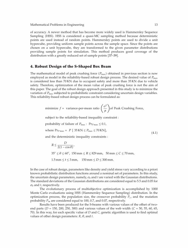
Figure 9: The impact model of the S-shaped box beam with loading and boundary conditions.
5004003002001000
Displacement (mm)
0
1000
2000
3000
4000
5000
6000
Abs
orbe
den
ergy
(J)
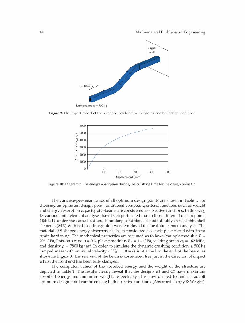
Figure 10: Diagram of the energy absorption during the crushing time for the design point C1.
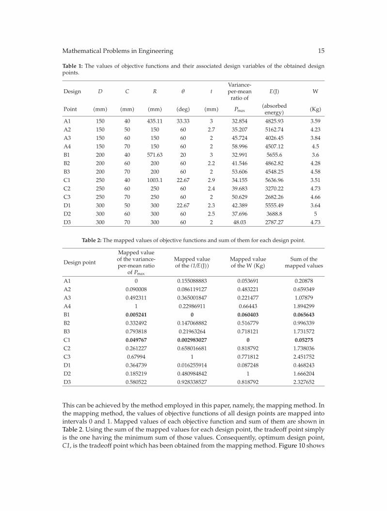
The variance-per-mean ratios of all optimum design points are shown in Table 1. Forchoosing an optimum design point, additional competing criteria functions such as weightand energy absorption capacity of S-beams are considered as objective functions. In this way,13 various finite-element analyses have been performed due to those different design points(Table 1) under the same load and boundary conditions. 4-node doubly curved thin-shellelements (S4R) with reduced integration were employed for the finite-element analysis. Thematerial of S-shaped energy absorbers has been considered as elastic-plastic steel with linearstrain hardening. The mechanical properties are assumed as follows: Young’s modulus E =206 GPa, Poisson’s ratio υ = 0.3, plastic modulus ET = 1.4 GPa, yielding stress σ0 = 162 MPa,and density ρ = 7800 kg/m3. In order to simulate the dynamic crushing condition, a 500 kglumped mass with an initial velocity of V0 = 10 m/s is attached to the end of the beam, asshown in Figure 9. The rear end of the beam is considered free just in the direction of impactwhilst the front end has been fully clamped.
The computed values of the absorbed energy and the weight of the structure aredepicted in Table 1. The results clearly reveal that the designs B1 and C1 have maximumabsorbed energy and minimum weight, respectively. It is now desired to find a tradeoffoptimum design point compromising both objective functions (Absorbed energy & Weight).
Mathematical Problems in Engineering 15
Table 1: The values of objective functions and their associated design variables of the obtained designpoints.
Design D C R θ tVariance-per-mean
ratio ofE(J) W
Point (mm) (mm) (mm) (deg) (mm) Pmax(absorbed
energy) (Kg)
A1 150 40 435.11 33.33 3 32.854 4825.93 3.59A2 150 50 150 60 2.7 35.207 5162.74 4.23A3 150 60 150 60 2 45.724 4026.45 3.84A4 150 70 150 60 2 58.996 4507.12 4.5B1 200 40 571.63 20 3 32.991 5655.6 3.6B2 200 60 200 60 2.2 41.546 4862.82 4.28B3 200 70 200 60 2 53.606 4548.25 4.58C1 250 40 1003.1 22.67 2.9 34.155 5636.96 3.51C2 250 60 250 60 2.4 39.683 3270.22 4.73C3 250 70 250 60 2 50.629 2682.26 4.66D1 300 50 300 22.67 2.3 42.389 5555.49 3.64D2 300 60 300 60 2.5 37.696 3688.8 5D3 300 70 300 60 2 48.03 2787.27 4.73
Table 2: The mapped values of objective functions and sum of them for each design point.
Design point
Mapped valueof the variance-per-mean ratio
of Pmax
Mapped valueof the (1/E(J))
Mapped valueof the W (Kg)
Sum of themapped values
A1 0 0.155088883 0.053691 0.20878A2 0.090008 0.086119127 0.483221 0.659349A3 0.492311 0.365001847 0.221477 1.07879A4 1 0.22986911 0.66443 1.894299B1 0.005241 0 0.060403 0.065643
B2 0.332492 0.147068882 0.516779 0.996339B3 0.793818 0.21963264 0.718121 1.731572C1 0.049767 0.002983027 0 0.05275
C2 0.261227 0.658016681 0.818792 1.738036C3 0.67994 1 0.771812 2.451752D1 0.364739 0.016255914 0.087248 0.468243D2 0.185219 0.480984842 1 1.666204D3 0.580522 0.928338527 0.818792 2.327652
This can be achieved by the method employed in this paper, namely, the mapping method. Inthe mapping method, the values of objective functions of all design points are mapped intointervals 0 and 1. Mapped values of each objective function and sum of them are shown inTable 2. Using the sum of the mapped values for each design point, the tradeoff point simplyis the one having the minimum sum of those values. Consequently, optimum design point,C1, is the tradeoff point which has been obtained from the mapping method. Figure 10 shows
16 Mathematical Problems in Engineering
Displacement = 0 mm
(a)
Displacement = 150 mm
(b)
Displacement = 250 mm
(c)
Displacement = 400 mm
(d)
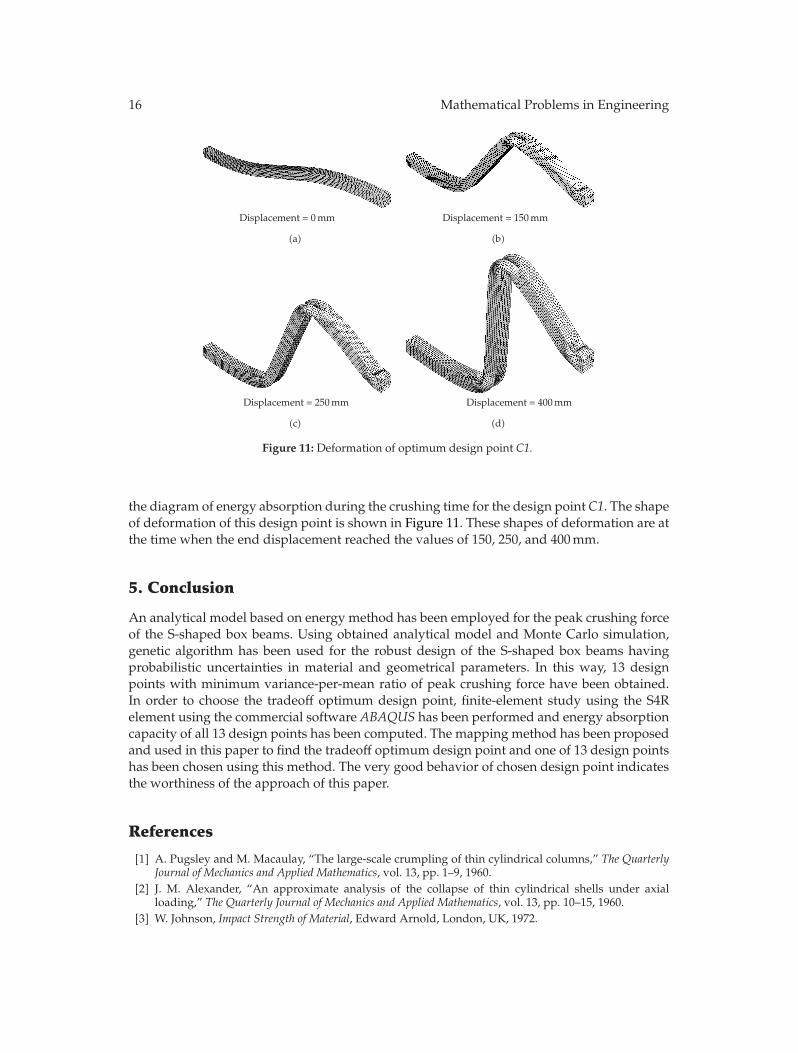
Figure 11: Deformation of optimum design point C1.
the diagram of energy absorption during the crushing time for the design point C1. The shapeof deformation of this design point is shown in Figure 11. These shapes of deformation are atthe time when the end displacement reached the values of 150, 250, and 400 mm.
5. Conclusion
An analytical model based on energy method has been employed for the peak crushing forceof the S-shaped box beams. Using obtained analytical model and Monte Carlo simulation,genetic algorithm has been used for the robust design of the S-shaped box beams havingprobabilistic uncertainties in material and geometrical parameters. In this way, 13 designpoints with minimum variance-per-mean ratio of peak crushing force have been obtained.In order to choose the tradeoff optimum design point, finite-element study using the S4Relement using the commercial software ABAQUS has been performed and energy absorptioncapacity of all 13 design points has been computed. The mapping method has been proposedand used in this paper to find the tradeoff optimum design point and one of 13 design pointshas been chosen using this method. The very good behavior of chosen design point indicatesthe worthiness of the approach of this paper.
References
[1] A. Pugsley and M. Macaulay, “The large-scale crumpling of thin cylindrical columns,” The QuarterlyJournal of Mechanics and Applied Mathematics, vol. 13, pp. 1–9, 1960.
[2] J. M. Alexander, “An approximate analysis of the collapse of thin cylindrical shells under axialloading,” The Quarterly Journal of Mechanics and Applied Mathematics, vol. 13, pp. 10–15, 1960.
[3] W. Johnson, Impact Strength of Material, Edward Arnold, London, UK, 1972.
Mathematical Problems in Engineering 17
[4] N. Jones and W. Abramowicz, “Static and dynamic axial crushing of circular and square tubes,” inMetal Forming and Impact Mechanics, S. R. Reid, Ed., p. 225, Pergamon Press, Oxford, UK, 1985.
[5] T. Wierzbicki, S. U. Bhat, W. Abramowicz, and D. Brodkin, “Alexander revisited—a two foldingelements model of progressive crushing of tubes,” International Journal of Solids and Structures, vol.29, no. 24, pp. 3269–3288, 1992.
[6] A. A. Singace, H. Elsobky, and T. Y. Reddy, “On the eccentricity factor in the progressive crushing oftubes,” International Journal of Solids and Structures, vol. 32, no. 24, pp. 3589–3602, 1995.
[7] N. K. Gupta and R. Velmurugan, “Consideration of internal folding and non-symmetric foldformation in axisymmetric axial collapse of round tubes,” International Journal of Solids and Structures,vol. 34, no. 20, pp. 2611–2630, 1997.
[8] Y. Ohkami, M. Shimamura, K. Takada, H. Tomizawa, K. Motomura, and M. Usuda, “Collapse of thin-walled curved beam with closed-hat section. Part 1. Study on collapse characteristics,” in ElectronicDiesel Engine Controls—Papers Presented at the SAE International Congress and Exposition, pp. 1–12,Detroit, Mich, USA, March 1990, SAE Paper 900460.
[9] C. M. Ni, “Impact response of curved box beam columns withlarge global and local deformations,”in Proceedings of the 14thStructures, Structural Dynamics, and Materials Conference, King of Prussia, Pa,USA, 1976, AIAA Paper 73-401.
[10] H.-S. Kim and T. Wierzbicki, “Effect of the cross-sectional shape on crash behavior of a 3-D spaceframe. Impact and Crashworthiness Laboratory,” Tech. Rep. 34, MIT, May 2000.
[11] H.-S. Kim and T. Wierzbicki, “Closed-form solution for crushing response of three-dimensional thin-walled ”S” frames with rectangular cross-sections,” International Journal of Impact Engineering, vol. 30,no. 1, pp. 87–112, 2004.
[12] L. Zheng and T. Wierzbicki, “Quasi-static crushing of S-shaped aluminum front rail,” InternationalJournal of Crashworthiness, vol. 9, no. 2, pp. 155–173, 2004.
[13] P. Hosseini-Tehrani and M. Nikahd, “Two materials S-frame representation for improving crashwor-thiness and lightening,” Thin-Walled Structures, vol. 44, no. 4, pp. 407–414, 2006.
[14] Y. Liu and M. L. Day, “Bending collapse of thin-walled circular tubes and computational application,”Thin-Walled Structures, vol. 46, no. 4, pp. 442–450, 2008.
[15] A. Jamali, A. Hajiloo, and N. Nariman-zadeh, “Reliability-based robust Pareto design of linear statefeedback controllers using a multi-objective uniform-diversity genetic algorithm (MUGA),” ExpertSystems with Applications, vol. 37, no. 1, pp. 401–413, 2010.
[16] D. Lonn, M. Oman, L. Nilsson, and K. Simonsson, “Finite element based robustness study of a truckcab subjected to impact loading,” International Journal of Crashworthiness, vol. 14, no. 2, pp. 111–124,2009.
[17] I. Kucuk, S. Adali, and I. Sadek, “Robust optimal design of beams subject to uncertain loads,”Mathematical Problems in Engineering, vol. 2009, Article ID 841017, 17 pages, 2009.
[18] G. Augusti, A. Baratta, and F. Casciati, Probabilistic Methods in Structural Engineering, Chapman & Hall,London, UK, 1984.
[19] G. Augusti and A. Baratta, “Limit analysis of structures with stochastic strength variation,” Journal ofStructural Mechanics, vol. 1, no. 1, pp. 43–62, 1972.
[20] U. Alibrandi and G. Ricciardi, “The use stochastic stresses in the static approach of probabilistic limitanalysis,” International Journal for Numerical Methods in Engineering, vol. 73, no. 6, pp. 747–782, 2008.
[21] O. Ditlevsen and O. H. Madsen, Structural Reliability Methods, John Wiley & Sons, New York, NY,USA, 1996.
[22] H. G. Matthies, C. E. Brenner, C. G. Bucher, and C. G. Soares, “Uncertainties in probabilistic numericalanalysis of structures and solids—stochastic finite elements,” Structural Safety, vol. 19, no. 3, pp. 283–336, 1997.
[23] S. Okazawa, K. Oide, K. Ikeda, and K. Terada, “Imperfection sensitivity and probabilistic variationof tensile strength of steel members,” International Journal of Solids and Structures, vol. 39, no. 6, pp.1651–1671, 2002.
[24] C. A. Schenk and G. I. Schueller, Uncertainty Assessment of Large Finite Element Systems, Springer,Berlin, Germany, 2005.
[25] D. Lim, Y. S. Ong, and B. S. Lee, “Inverse multi-objective robust evolutionary design optimization inthe presence of uncertainty,” in Proceedings of the Workshops on Genetic and Evolutionary Computation(GECCO ’05), pp. 55–62, Washington, DC, USA, 2005.
[26] M. Papadrakakis, N. D. Lagaros, and V. Plevris, “Structural optimization considering the probabilisticsystem response,” International Journal of Theoretical Applied Mechanics, vol. 31, no. 3-4, pp. 361–393, 34.
[27] J. S. Arora, Introduction to Optimum Design, McGraw-Hill, New York, NY, USA, 1989.
18 Mathematical Problems in Engineering
[28] S. S. Rao, Engineering Optimization: Theory and Practice, John Wiley & Sons, New York, NY, USA, 1996.[29] N. Amanifard, N. Nariman-Zadeh, M. Borji, A. Khalkhali, and A. Habibdoust, “Modelling and
Pareto optimization of heat transfer and flow coefficients in microchannels using GMDH type neuralnetworks and genetic algorithms,” Energy Conversion and Management, vol. 49, no. 2, pp. 311–325,2008.
[30] K. Atashkari, N. Nariman-Zadeh, M. Golcu, A. Khalkhali, and A. Jamali, “Modelling and multi-objective optimization of a variable valve-timing spark-ignition engine using polynomial neuralnetworks and evolutionary algorithms,” Energy Conversion and Management, vol. 48, no. 3, pp. 1029–1041, 2007.
[31] D. E. Goldberg, Genetic Algorithms in Search, Optimization, and Machine Learning, Addison-Wesley,Boston, Mass, USA, 1989.
[32] T. Back, D. B. Fogel, and Z. Michalewic, Eds., Handbook of Evolutionary Computation, Institute of PhysicsPublishing, Bristol, UK; Oxford University Press, New York, NY, USA, 1997.
[33] G. Renner and A. Ekart, “Genetic algorithms in computer aided design,” CAD Computer Aided Design,vol. 35, no. 8, pp. 709–726, 2003.
[34] Q. Wang and R. F. Stengel, “Robust control of nonlinear systems with parametric uncertainty,”Automatica, vol. 38, no. 9, pp. 1591–1599, 2002.
[35] M. H. Kalos and P. A. Whitlock, Monte Carlo Methods, Wiley-Blackwell, Weinheim, Germany, 2ndedition, 2008.
[36] Z. Kang, Robust design of structures under uncertainties, Ph.D. thesis, University of Stuttgart, 2005.[37] B. A. Smith, S. P. Kenny, and L. G. Crespo, “Probabilistic parameter uncertainty analysis of single
input single output control systems,” NASA Report TM-2005-213280, NASA, 2005.[38] L. G. Crespo and S. P. Kenny, “Robust control deign for systems with probabilistic uncertainty,” NASA
Report TP-2005-213531, NASA, 2005.[39] U. M. Diwekar and J. R. Kalagnanam, “Efficient sampling technique for optimization under
uncertainty,” AIChE Journal, vol. 43, no. 2, pp. 440–447, 1997.

Impact Factor 1.73028 Days Fast Track Peer ReviewAll Subject Areas of ScienceSubmit at http://www.tswj.com
Hindawi Publishing Corporation http://www.hindawi.com Volume 2013Hindawi Publishing Corporation http://www.hindawi.com Volume 2013
The Scientific World Journal
Related Documents