IEEE TRANSACTIONS ON MEDICAL IMAGING, VOL. 30, NO. 12, DECEMBER 2011 2087 Robust Automatic Knee MR Slice Positioning Through Redundant and Hierarchical Anatomy Detection Yiqiang Zhan*, Maneesh Dewan, Martin Harder, Arun Krishnan, and Xiang Sean Zhou Abstract—Diagnostic magnetic resonance (MR) image quality is highly dependent on the position and orientation of the slice groups, due to the intrinsic high in-slice and low through-slice resolutions of MR imaging. Hence, the higher speed, accuracy, and reproducibility of automatic slice positioning [1], [2] make it highly desirable over manual slice positioning. However, imaging artifacts, diseases, joint articulation, variations across ages and demographics as well as the extremely high performance re- quirements prevent state-of-the-art methods, such as volumetric registration, to be an off-the-shelf solution. In this paper, we address all these issues through an automatic slice positioning framework based on redundant and hierarchical learning. Our method has two hallmarks that are specifically designed to achieve high robustness and accuracy. 1) A redundant set of anatomy detectors are learned to provide local appearance cues. These detections are pruned and assembled according to a distributed anatomy model, which captures group-wise spatial configurations among anatomy primitives. This strategy brings about a high level of robustness and works even if a large portion of the target is distorted, missing, or occluded. 2) The detectors are learned and invoked in a hierarchical fashion, with each local detection sched- uled and iterated according to its intrinsic invariance property. This iterative alignment process is shown to dramatically improve alignment accuracy. The proposed system is extensively validated on a large dataset including 744 clinical MR scans. Compared to state-of-the-art methods, our method exhibits superior perfor- mance in terms of robustness, accuracy, and reproducibility. The methodology is general and can be applied to other anatomies and other imaging modalities. Index Terms—Computer aided detection, knee, magnetic reso- nance imaging, medical image analysis, pattern recognition, slice positioning. I. INTRODUCTION M AGNETIC resonance imaging (MRI) has been success- fully used to diagnose various knee diseases ranging from acute knee injuries to chronic knee dysfunction, e.g., ligament tears, patella dislocation, meniscal pathology and Manuscript received April 08, 2011; revised June 25, 2011; accepted July 01, 2011. Date of publication July 22, 2011; date of current version December 02, 2011. Asterisk indicates corresponding author. *Y. Zhan is with the SYNGO division, Siemens Medical Solutions, Malvern, PA 19355 USA (e-mail: [email protected]). M. Dewan, A. Krishnan, and X. S. Zhou are with the SYNGO division, Siemens Medical Solutions, Malvern, PA 19355 USA. M. Harder is with the MR Division, Siemens Healthcare, 91054 Erlangen, Germany. Color versions of one or more of the figures in this paper are available online at http://ieeexplore.ieee.org. Digital Object Identifier 10.1109/TMI.2011.2162634 arthropathies [3]. The inherent imaging physics and speed lim- itations of MR typically constrain the diagnostic MR images to have isotropic high resolution in 3-D. Instead, diagnostic MR image is a modality with high in-slice resolution and low through-slice resolution [Fig. 1(c)]. Hence, their diagnostic quality is highly dependent upon the positioning accuracy of the slice groups (imaging planes). Good centering and orienta- tion ensures that the anatomy of interest is optimally captured within the high-resolution (high-res) imaging plane. Traditionally, this is achieved by acquiring 2-D scout images (called “localizers”): technicians can then plan out high-res slice groups based on relevant anatomies visible in these scouts. Since a typical study often requires imaging of more than one knee structure (menisci, cruciate ligaments, femoral or patella car- tilages, etc.) with different slice positioning, often times, mul- tiple sets of scout images are required. The entire manual align- ment thus becomes very time-consuming. Furthermore, manual alignment using 2-D localizers is often not reproducible for follow-up studies—by “reproducible,” we mean that when a pa- tient comes back after several days/months of therapy/surgery, with a different knee bending angle or altered anatomy, it is im- portant to scan the target anatomy using the exact same imaging planes as the earlier study in order to make a well-founded judg- ment regarding the effect of the therapy/surgery. Recently, 3-D knee scout scan has been introduced to im- prove the quality of the workflow. A 3-D knee scout scan has low but isotropic resolution. Although it might not be of di- agnostic quality, it provides complete 3-D context which en- ables a human operator, or a computer, to plan out all required high-res slice groups without any additional scout scans. Fig. 1 shows an example of how to plan a high-res slice group using the 3-D scout in a reproducible way: to image the menisci, the transversal slice group should be parallel to the meniscus plane, and the in-plane rotation is determined by aligning to the line connecting the two lower edges of the femoral condyle (the yellow dashed line). Based on anatomy context in 3-D scout scan, technicians po- sition, i.e., apply rigid transformations to, one or multiple slice groups for the follow-up high-res scans. This manual process is usually time consuming, owing to the complexity of the task, the 3-D nature of the problem (humans cannot see/process 3-D volumetric data directly but rather can only see one cut-plane at a time), and the high requirements on accuracy and repro- ducibility. While some studies have already demonstrated the added clinical value of the auto-slice-positioning in MR brain workflow [1], [4], researchers started to study the feasibility of 0278-0062/$26.00 © 2011 IEEE

Welcome message from author
This document is posted to help you gain knowledge. Please leave a comment to let me know what you think about it! Share it to your friends and learn new things together.
Transcript
IEEE TRANSACTIONS ON MEDICAL IMAGING, VOL. 30, NO. 12, DECEMBER 2011 2087
Robust Automatic Knee MR Slice PositioningThrough Redundant and Hierarchical
Anatomy DetectionYiqiang Zhan*, Maneesh Dewan, Martin Harder, Arun Krishnan, and Xiang Sean Zhou
Abstract—Diagnostic magnetic resonance (MR) image qualityis highly dependent on the position and orientation of the slicegroups, due to the intrinsic high in-slice and low through-sliceresolutions of MR imaging. Hence, the higher speed, accuracy,and reproducibility of automatic slice positioning [1], [2] make ithighly desirable over manual slice positioning. However, imagingartifacts, diseases, joint articulation, variations across ages anddemographics as well as the extremely high performance re-quirements prevent state-of-the-art methods, such as volumetricregistration, to be an off-the-shelf solution. In this paper, weaddress all these issues through an automatic slice positioningframework based on redundant and hierarchical learning. Ourmethod has two hallmarks that are specifically designed to achievehigh robustness and accuracy. 1) A redundant set of anatomydetectors are learned to provide local appearance cues. Thesedetections are pruned and assembled according to a distributedanatomy model, which captures group-wise spatial configurationsamong anatomy primitives. This strategy brings about a high levelof robustness and works even if a large portion of the target isdistorted, missing, or occluded. 2) The detectors are learned andinvoked in a hierarchical fashion, with each local detection sched-uled and iterated according to its intrinsic invariance property.This iterative alignment process is shown to dramatically improvealignment accuracy. The proposed system is extensively validatedon a large dataset including 744 clinical MR scans. Compared tostate-of-the-art methods, our method exhibits superior perfor-mance in terms of robustness, accuracy, and reproducibility. Themethodology is general and can be applied to other anatomies andother imaging modalities.
Index Terms—Computer aided detection, knee, magnetic reso-nance imaging, medical image analysis, pattern recognition, slicepositioning.
I. INTRODUCTION
M AGNETIC resonance imaging (MRI) has been success-fully used to diagnose various knee diseases ranging
from acute knee injuries to chronic knee dysfunction, e.g.,ligament tears, patella dislocation, meniscal pathology and
Manuscript received April 08, 2011; revised June 25, 2011; accepted July 01,2011. Date of publication July 22, 2011; date of current version December 02,2011. Asterisk indicates corresponding author.
*Y. Zhan is with the SYNGO division, Siemens Medical Solutions, Malvern,PA 19355 USA (e-mail: [email protected]).
M. Dewan, A. Krishnan, and X. S. Zhou are with the SYNGO division,Siemens Medical Solutions, Malvern, PA 19355 USA.
M. Harder is with the MR Division, Siemens Healthcare, 91054 Erlangen,Germany.
Color versions of one or more of the figures in this paper are available onlineat http://ieeexplore.ieee.org.
Digital Object Identifier 10.1109/TMI.2011.2162634
arthropathies [3]. The inherent imaging physics and speed lim-itations of MR typically constrain the diagnostic MR imagesto have isotropic high resolution in 3-D. Instead, diagnosticMR image is a modality with high in-slice resolution andlow through-slice resolution [Fig. 1(c)]. Hence, their diagnosticquality is highly dependent upon the positioning accuracy ofthe slice groups (imaging planes). Good centering and orienta-tion ensures that the anatomy of interest is optimally capturedwithin the high-resolution (high-res) imaging plane.
Traditionally, this is achieved by acquiring 2-D scout images(called “localizers”): technicians can then plan out high-res slicegroups based on relevant anatomies visible in these scouts. Sincea typical study often requires imaging of more than one kneestructure (menisci, cruciate ligaments, femoral or patella car-tilages, etc.) with different slice positioning, often times, mul-tiple sets of scout images are required. The entire manual align-ment thus becomes very time-consuming. Furthermore, manualalignment using 2-D localizers is often not reproducible forfollow-up studies—by “reproducible,” we mean that when a pa-tient comes back after several days/months of therapy/surgery,with a different knee bending angle or altered anatomy, it is im-portant to scan the target anatomy using the exact same imagingplanes as the earlier study in order to make a well-founded judg-ment regarding the effect of the therapy/surgery.
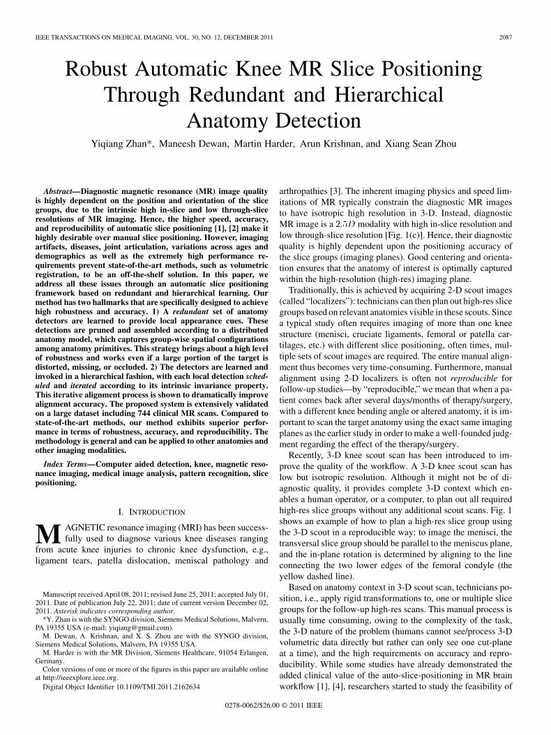
Recently, 3-D knee scout scan has been introduced to im-prove the quality of the workflow. A 3-D knee scout scan haslow but isotropic resolution. Although it might not be of di-agnostic quality, it provides complete 3-D context which en-ables a human operator, or a computer, to plan out all requiredhigh-res slice groups without any additional scout scans. Fig. 1shows an example of how to plan a high-res slice group usingthe 3-D scout in a reproducible way: to image the menisci, thetransversal slice group should be parallel to the meniscus plane,and the in-plane rotation is determined by aligning to the lineconnecting the two lower edges of the femoral condyle (theyellow dashed line).
Based on anatomy context in 3-D scout scan, technicians po-sition, i.e., apply rigid transformations to, one or multiple slicegroups for the follow-up high-res scans. This manual process isusually time consuming, owing to the complexity of the task,the 3-D nature of the problem (humans cannot see/process 3-Dvolumetric data directly but rather can only see one cut-planeat a time), and the high requirements on accuracy and repro-ducibility. While some studies have already demonstrated theadded clinical value of the auto-slice-positioning in MR brainworkflow [1], [4], researchers started to study the feasibility of
0278-0062/$26.00 © 2011 IEEE
2088 IEEE TRANSACTIONS ON MEDICAL IMAGING, VOL. 30, NO. 12, DECEMBER 2011
Fig. 1. MR slice positioning using scout scans. (a) Workflow of knee MR scans.(b) A MR knee scout scan. Rectangle boxes: coverage of MR slice group. Cir-cles: imaging centers. Yellow dashed line (in the small thumbnail) defines thein-plane rotation. (c) A typical high-resolution diagnostic MR knee transversalscan.
the auto-slice-positioning in MR knee workflow. In [2], an au-tomatic slice positioning algorithm [5] is evaluated on 50 kneescans (three slice boxes each). It shows comparable quality tomanual positioning . Although the algorithm perfor-mance still has the space to improve, (see details in Section II)this study did show the potential of automatic slice positioningin clinical practice. In this paper, we aim to design a highly ro-bust auto-positioning algorithm, which is expected to improvethe speed, accuracy, and reproducibility of the MR knee imagingworkflow.
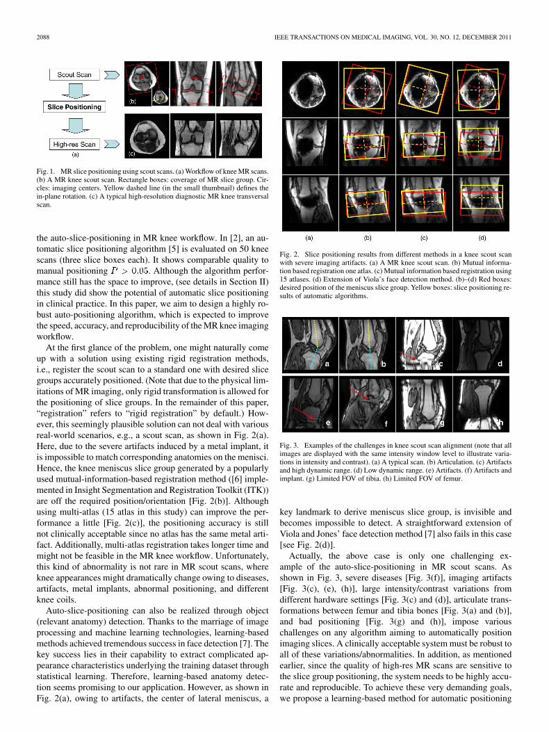
At the first glance of the problem, one might naturally comeup with a solution using existing rigid registration methods,i.e., register the scout scan to a standard one with desired slicegroups accurately positioned. (Note that due to the physical lim-itations of MR imaging, only rigid transformation is allowed forthe positioning of slice groups. In the remainder of this paper,“registration” refers to “rigid registration” by default.) How-ever, this seemingly plausible solution can not deal with variousreal-world scenarios, e.g., a scout scan, as shown in Fig. 2(a).Here, due to the severe artifacts induced by a metal implant, itis impossible to match corresponding anatomies on the menisci.Hence, the knee meniscus slice group generated by a popularlyused mutual-information-based registration method ([6] imple-mented in Insight Segmentation and Registration Toolkit (ITK))are off the required position/orientation [Fig. 2(b)]. Althoughusing multi-atlas (15 atlas in this study) can improve the per-formance a little [Fig. 2(c)], the positioning accuracy is stillnot clinically acceptable since no atlas has the same metal arti-fact. Additionally, multi-atlas registration takes longer time andmight not be feasible in the MR knee workflow. Unfortunately,this kind of abnormality is not rare in MR scout scans, whereknee appearances might dramatically change owing to diseases,artifacts, metal implants, abnormal positioning, and differentknee coils.
Auto-slice-positioning can also be realized through object(relevant anatomy) detection. Thanks to the marriage of imageprocessing and machine learning technologies, learning-basedmethods achieved tremendous success in face detection [7]. Thekey success lies in their capability to extract complicated ap-pearance characteristics underlying the training dataset throughstatistical learning. Therefore, learning-based anatomy detec-tion seems promising to our application. However, as shown inFig. 2(a), owing to artifacts, the center of lateral meniscus, a
Fig. 2. Slice positioning results from different methods in a knee scout scanwith severe imaging artifacts. (a) A MR knee scout scan. (b) Mutual informa-tion based registration one atlas. (c) Mutual information based registration using15 atlases. (d) Extension of Viola’s face detection method. (b)–(d) Red boxes:desired position of the meniscus slice group. Yellow boxes: slice positioning re-sults of automatic algorithms.
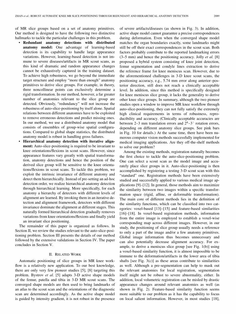
Fig. 3. Examples of the challenges in knee scout scan alignment (note that allimages are displayed with the same intensity window level to illustrate varia-tions in intensity and contrast). (a) A typical scan. (b) Articulation. (c) Artifactsand high dynamic range. (d) Low dynamic range. (e) Artifacts. (f) Artifacts andimplant. (g) Limited FOV of tibia. (h) Limited FOV of femur.
key landmark to derive meniscus slice group, is invisible andbecomes impossible to detect. A straightforward extension ofViola and Jones’ face detection method [7] also fails in this case[see Fig. 2(d)].
Actually, the above case is only one challenging ex-ample of the auto-slice-positioning in MR scout scans. Asshown in Fig. 3, severe diseases [Fig. 3(f)], imaging artifacts[Fig. 3(c), (e), (h)], large intensity/contrast variations fromdifferent hardware settings [Fig. 3(c) and (d)], articulate trans-formations between femur and tibia bones [Fig. 3(a) and (b)],and bad positioning [Fig. 3(g) and (h)], impose variouschallenges on any algorithm aiming to automatically positionimaging slices. A clinically acceptable system must be robust toall of these variations/abnormalities. In addition, as mentionedearlier, since the quality of high-res MR scans are sensitive tothe slice group positioning, the system needs to be highly accu-rate and reproducible. To achieve these very demanding goals,we propose a learning-based method for automatic positioning
ZHAN et al.: ROBUST AUTOMATIC KNEE MR SLICE POSITIONING THROUGH REDUNDANT AND HIERARCHICAL ANATOMY DETECTION 2089
of MR slice groups based on a set of anatomy primitives.Our method is designed to have the following two distinctivehallmarks to tackle the particular challenges in this problem.
• Redundant anatomy detections with distributedanatomy model: One advantage of learning-baseddetection is its capability to handle large appearancevariations. However, learning-based detection is not im-mune to severe diseases/artifacts in MR scout scans, asthis kind of dramatic and random appearance changescannot be exhaustively captured in the training dataset.To achieve high robustness, we go beyond the immediatetarget structure and employ “more than enough” anatomyprimitives to derive slice groups. For example, in theory,three noncollinear points can exclusively determine arigid transformation. In our method, however, a far greaternumber of anatomies relevant to the slice group aredetected. Obviously, “redundancy” will not increase therobustness of auto-slice-positioning by itself alone. Spatialrelations between different anatomies have to be exploitedto remove erroneous detections and predict missing ones.In our method, we use a distributed anatomy model thatconsists of ensembles of group-wise spatial configura-tions. Compared to global shape statistics, the distributedanatomy model is robust in handling gross failures.
• Hierarchical anatomy detection with iterative align-ment: Auto-slice-positioning is required to be invariant toknee orientations/flexions in scout scans. However, sinceappearance features vary greatly with spatial transforma-tion, anatomy detections and hence the position of thederived slice group will be sensitive to the knee orienta-tions/flexions in scout scans. To tackle this problem, weexploit the intrinsic invariance of different anatomy anddetect them hierarchically. Instead of pre-setting an ad-hocdetection order, we realize hierarchical anatomy detectionthrough hierarchical learning. More specifically, for eachanatomy a hierarchy of detectors with different levels ofalignment are learned. By invoking them in an iterative de-tection and alignment framework, detectors with differentinvariance dominate the alignment at different stages. Thisnaturally formed hierarchical detection gradually removesvariations from knee orientations/flexions and finally yieldan invariant slice positioning.
The remainder of this paper is organized as follows. InSection II, we review the studies relevant to the auto-slice-posi-tioning problem. Section III presents the details of our methodfollowed by the extensive validations in Section IV. The paperconcludes in Section V.
II. RELATED WORK
Automatic positioning of slice groups in MR knee work-flow is a relatively new application. To our best knowledge,there are only very few pioneer studies [5], [8] targeting thisproblem. Bystrov et al. [5] adapts 3-D active shape modelsof the femur, patella and tibia in 3-D MR scout scans. Theconverged shape models are then used to bring landmarks ofan atlas to the scout scan and the orientations of the diagnosticscan are determined accordingly. As the active shape modelis guided by intensity gradient, it is not robust in the presence
of severe artifacts/diseases (as shown in Fig. 3). In addition,active shape model cannot guarantee a precise correspondencesduring deformation. Even when the converged shape modelmatches the organ boundaries exactly, some landmarks mightstill be off their exact correspondences in the scout scan. Bothfactors probably contribute to the reported landmarking errors(3–5 mm) and hence the positioning accuracy. Jolly et al. [8]proposed a hybrid system consisting of knee joint detection,femur segmentation and condyle lines extraction to derivethe reference frame for knee meniscus scan. However, due tothe aforementioned challenges in 3-D knee scout scans, thepositioning accuracy, e.g., 5.74 mm error along anterior–pos-terior direction, still does not reach a clinically acceptablelevel. In addition, since this method is specifically designedfor knee meniscus slice group, it lacks the generality to deriveother knee slice groups. In summary, although the two pioneerstudies open a window to improve MR knee workflow throughauto-slice-positioning, they can not fully satisfy the extremelyhigh clinical requirements in terms of robustness, repro-ducibility and accuracy. (Clinically acceptable accuracies arebetween 2–3 mm translation errors and 2 –3 rotation errors,depending on different anatomy slice groups. See pink barsin Fig. 10 for details.) At the same time, there have been nu-merous computer vision methods successfully implemented formedical imaging applications. Are they off-the-shelf methodsto solve our problem?
Among the existing methods, registration naturally becomesthe first choice to tackle the auto-slice-positioning problem.One can select a scout scan as the model image and accu-rately place slice groups in it. Auto-slice-positioning is thenaccomplished by registering a testing 3-D scout scan with this“standard” one. Registration methods have been extensivelystudied and successfully applied to various medical image ap-plications [9]–[12]. In general, those methods aim to maximizethe similarity between two images within a specific transfor-mation space (rigid, affine, or deformable transformation).The main core of different methods lies in the definition ofthe similarity functions, which can be classified into two cat-egories: voxel-based [13]–[15] and feature-based similarities[16]–[18]. In voxel-based registration methods, informationfrom the entire image is employed to establish a voxel-wisecorresponding map across different images. However, in ourstudy, the positioning of slice group usually needs a referenceto only a part of the image and/or a few anatomy primitives.Global image information thus becomes unnecessary andcan also potentially decrease alignment accuracy. For ex-ample, to derive a meniscus slice group [see Fig. 1(b)] usinga voxel-based similarity function, it is almost impossible to beimmune to the deformation/artifacts in the lower area of tibiashafts [see Fig. 3(c)] as these areas contribute to similaritiesas well. Although a pre-segmentation can help to mask outthe relevant anatomies for local registration, segmentationitself might not be robust to severe abnormality, either. Inaddition, local volumetric registration can be misled by drasticappearance changes around relevant anatomies as well (asshown in Fig. 2). Feature-based similarity function seemsmore suitable to our problem as it has the capability to focuson local salient information. However, in most studies [18],
2090 IEEE TRANSACTIONS ON MEDICAL IMAGING, VOL. 30, NO. 12, DECEMBER 2011
[19], [12], features are defined by low level salient structures,e.g., boundary points, crest lines. As these features do notbear exclusive anatomy definitions, the matching of featurescan not guarantee the matching of corresponding anatomies.(Note that corresponding anatomies might not always appearas salient structures due to diseases and imaging artifacts.) Inaddition, the positioning of MR slice groups only allows rigidtransformation and the conversion from deformation fields torigid transformation is still an open problem. Therefore, thosedeformable registration methods [15], [14], which achievetremendous successes in other applications, might not be appli-cable in our study.
Another class of extensively studied methods, object detec-tion, can also be employed for auto-slice-positioning. If rele-vant anatomy primitives are accurately detected, they can beused as local appearance cues to derive the position of the slicegroups. Thanks to the marriage of computer vision and ma-chine learning technologies, learning-based methods achievestremendous success in detecting different objects, e.g., faces [7],cars [20], and pedestrians [21]. The extension of these learning-based algorithms to 3-D gives the ability to model complexanatomy appearance and achieve robust detection to variationsacross patient sizes, demographics, and ages. However, for ourapplication, a straightforward learning-based detection methodwould still be lacking, mainly in two aspects. First, the abilityto handle “moderate-to-severe” disease, artifact, and bad posi-tioning. These abnormalities dramatically change the appear-ance of anatomies or might even render them invisible. Sincethese cases might not even exist in the training set, learning-based detection has high probability to fail. Second, the de-pendence of accuracy on the object pose. It is well known thatthe appearance features are sensitive to spatial transformation,thereby making the learning-based detection dependent on thepose of the object. Indeed this problem has been noticed inthe area of face detection and a few methods have been pro-posed to estimate face poses. In [22], face detectors for differentposes are exclusively performed and the pose correspondingto the detector with the strongest response is regarded as thealigned pose. [23] employs local orientation analysis to esti-mate face poses. Advanced machine learning technologies werealso applied to estimate face poses, including ANN [24], vectorboosting [25], SVM-based clustering [26], and convolutionalnetwork [27]. These successful methods can not be directly bor-rowed to our application due to the inherent differences be-tween face and knee: 1) knee has a more complex 3-D trans-formation including articulation and 2) the accuracy of kneeslice positioning (2 –3 ) is much higher than face alignment(up to 10 ). Recently, marginal space learning (MSL) [28] hasshown promise in estimating rough transformations of anatom-ical structures in medical images. The basic idea is to decom-pose the transformation parameters into location, orientation,and scale, etc., and train detectors to estimate each of them se-quentially. Since this method treats the target anatomy (e.g., aheart chamber or the knee menisci) as a whole, the burden oflearning is high especially for the first round of learning (lo-cation detectors). Specifically, all the possible variations, bothglobal and local, systematic or random, may not be fully learn-able in one shot; not to mention that all such variations may
not be fully represented in the training set. In addition, the de-pendency between sequential detectors adds another source offragility. For some challenging cases [as shown in Fig. 9(f)], ifthe first stage (location detection) makes a wrong decision, thefollowing steps (orientation and scale detections) will not cor-rect but further propagate the error. In this paper, we take a dif-ferent approach by decomposing the problem along the anatom-ical dimension. We adopt a completely local and distributed ap-proach, with each local detector pushed to the very basic oflocal appearance cues, which is a focal anatomical landmark.These local appearance cues are pruned and predicted by a dis-tributed (i.e., democratic thus robust) anatomy model to deriveslice positioning.
III. METHODS
A. Problem Statement and Formulation
As discussed in the previous section, none of the ex-isting methods alone can be an off-the-shelf solution to theMR auto-slice positioning problem. Nevertheless, the stronginsights provided by these methods to address particular chal-lenges have served as inspirations of our proposed approach.First, detection algorithms that are learned from examples pro-vide a generic and robust way of extracting complex appearancecharacteristics of anatomies, compared to “designing” differentanatomy-specific image filters that is usually time-consumingand nongeneralizable. Second, it is advantageous to learnseveral local anatomy primitives/landmarks instead of learningthe overall global anatomy (as MSL [28]). (In the remainderof this paper, anatomy primitives and landmarks refer to thesame thing by default.) Apart from the reduced load on thelearning framework, these local appearance cues provide thecapability to model complex transformation. Additionally, theylay the foundation for redundant and hierarchical detectionsas discussed later. It is worth noting that the “local” strategyis usually the way manual slice group positioning is done,where the technician positions and adjusts the high-res MRslice groups referring to a set of well-defined local anatomyprimitives. Third, “redundancy” is the key to achieving robustparsing of medical images, as discussed in [29]. This is espe-cially critical when abnormalities (disease, artifact, etc.) causelocal detections to fail. Hence, to be robust to such failures, ahighly redundant set of detectors (corresponding to relevantanatomies) need to be learned to provide local cues. These localcues are then assembled using learned spatial configurationsacross anatomy primitives. Lastly, given the dependence ofobject pose on detection accuracy, image/object alignmentneeds to be incorporated seamlessly in the learning framework.Additionally, it is interesting to mention that different anatomyprimitives have different intrinsic invariance with respect tospatial transformation (see Fig. 6). This characteristic shouldbe further exploited in building a transformation insensitiveand accurate detection scheme.
Using these principles, we propose a method to position theslice box based on a set of anatomical primitives detected bya learning-based method. To achieve high robustness and ac-curacy, we build the following. 1) A highly redundant set ofanatomy detectors: these redundant detections are pruned and
ZHAN et al.: ROBUST AUTOMATIC KNEE MR SLICE POSITIONING THROUGH REDUNDANT AND HIERARCHICAL ANATOMY DETECTION 2091
assembled by a learned distributed anatomy model. In this way,even though some anatomies are completely invisible, we canstill derive the slice boxes using the other visible ones. 2) Ahierarchy of detectors for each anatomy primitive: incorporatedthrough an iterative detection and alignment procedure, intrinsictransformation invariance of different anatomies are exploited.In the following subsections, we will present how these ideasare integrated in our formulation.
The process of positioning of a slice group is equivalent toaligning a MR scout scan to a canonical space in which the slicegroup is accurately positioned. Therefore, we start to formulateour method from a classic landmark-based alignment problem
(1)
Equation (1) is a typical least squares formula of a classical land-mark-based alignment. Here, denotes the detected landmarksin a MR scout scan and denotes corresponding landmarks inthe canonical space. Both and are vectors concatenated by3-D coordinates of landmarks. is the optimal transformationthat brings the scout scan to the canonical model space. Sincethe alignment and detection are highly dependent on each other,in order to estimate them jointly, (1) should be extended to in-corporate landmark detection
(2)
The first additional term, , denotes the likelihood ofthe landmark locations, given image (scout scan) and trans-formation . This term can be derived from anatomy detectorswhich capture the appearance characteristics of landmarks. It isworth noting that depends not only on image but also ontransformation . This is in accordance to the fact that appear-ance characteristics are influenced by transformations as well.The second additional term indicates the likelihood of thelandmark locations in terms of their spatial relations. In otherwords, this term incorporates high-level spatial statistics acrossdifferent anatomies and is exploited to make the alignment ro-bust to erroneous detections. (In (2), alignment residual has anexponential format such that it has the same value range as thesecond and third terms.) The current objective function, how-ever, still lacks “redundancy” and “hierarchy,” which are crit-ical to achieve robustness and accuracy, especially when abnor-mality exists (diseases, artifacts or bad positioning). Hence, (2)is further extended by inducing a selection matrix as
(3)
Here, is a diagonal matrix whose diagonal elements can beeither 1 or 0. It indicates whether an anatomy landmark is usedfor alignment. By inducing , three additional properties areintroduced into the alignment framework. First, can be de-fined to contain more than “necessary” anatomy landmarks. Forexample, although three noncollinear landmarks is enough toderive a rigid transformation, our system exploits much morelandmarks (redundancy) to achieve robustness. (Some represen-tative anatomy landmarks are shown in Fig. 4.) Second, givendifferent values of , the redundant landmarks can be adap-tively selected based on appearance (detection confidence) or
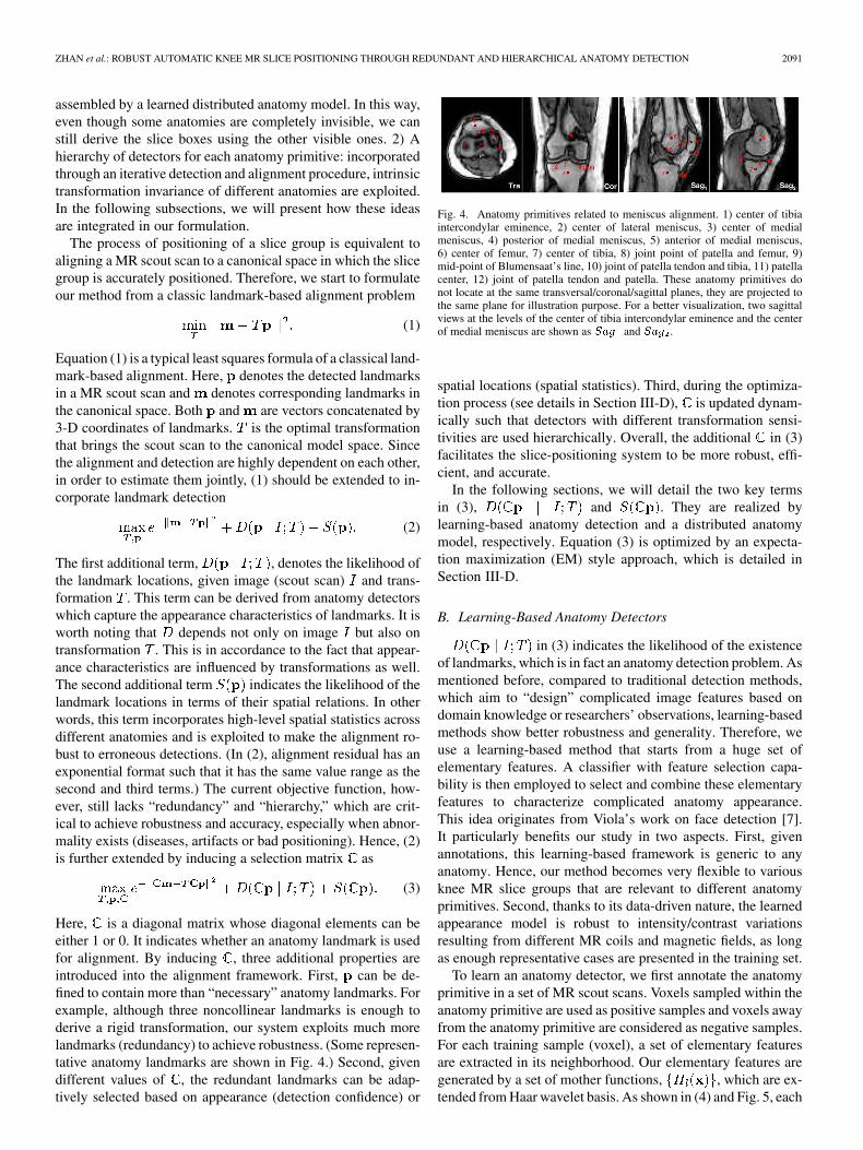
Fig. 4. Anatomy primitives related to meniscus alignment. 1) center of tibiaintercondylar eminence, 2) center of lateral meniscus, 3) center of medialmeniscus, 4) posterior of medial meniscus, 5) anterior of medial meniscus,6) center of femur, 7) center of tibia, 8) joint point of patella and femur, 9)mid-point of Blumensaat’s line, 10) joint of patella tendon and tibia, 11) patellacenter, 12) joint of patella tendon and patella. These anatomy primitives donot locate at the same transversal/coronal/sagittal planes, they are projected tothe same plane for illustration purpose. For a better visualization, two sagittalviews at the levels of the center of tibia intercondylar eminence and the centerof medial meniscus are shown as ��� and ��� .
spatial locations (spatial statistics). Third, during the optimiza-tion process (see details in Section III-D), is updated dynam-ically such that detectors with different transformation sensi-tivities are used hierarchically. Overall, the additional in (3)facilitates the slice-positioning system to be more robust, effi-cient, and accurate.
In the following sections, we will detail the two key termsin (3), and . They are realized bylearning-based anatomy detection and a distributed anatomymodel, respectively. Equation (3) is optimized by an expecta-tion maximization (EM) style approach, which is detailed inSection III-D.
B. Learning-Based Anatomy Detectors
in (3) indicates the likelihood of the existenceof landmarks, which is in fact an anatomy detection problem. Asmentioned before, compared to traditional detection methods,which aim to “design” complicated image features based ondomain knowledge or researchers’ observations, learning-basedmethods show better robustness and generality. Therefore, weuse a learning-based method that starts from a huge set ofelementary features. A classifier with feature selection capa-bility is then employed to select and combine these elementaryfeatures to characterize complicated anatomy appearance.This idea originates from Viola’s work on face detection [7].It particularly benefits our study in two aspects. First, givenannotations, this learning-based framework is generic to anyanatomy. Hence, our method becomes very flexible to variousknee MR slice groups that are relevant to different anatomyprimitives. Second, thanks to its data-driven nature, the learnedappearance model is robust to intensity/contrast variationsresulting from different MR coils and magnetic fields, as longas enough representative cases are presented in the training set.
To learn an anatomy detector, we first annotate the anatomyprimitive in a set of MR scout scans. Voxels sampled within theanatomy primitive are used as positive samples and voxels awayfrom the anatomy primitive are considered as negative samples.For each training sample (voxel), a set of elementary featuresare extracted in its neighborhood. Our elementary features aregenerated by a set of mother functions, , which are ex-tended from Haar wavelet basis. As shown in (4) and Fig. 5, each
2092 IEEE TRANSACTIONS ON MEDICAL IMAGING, VOL. 30, NO. 12, DECEMBER 2011
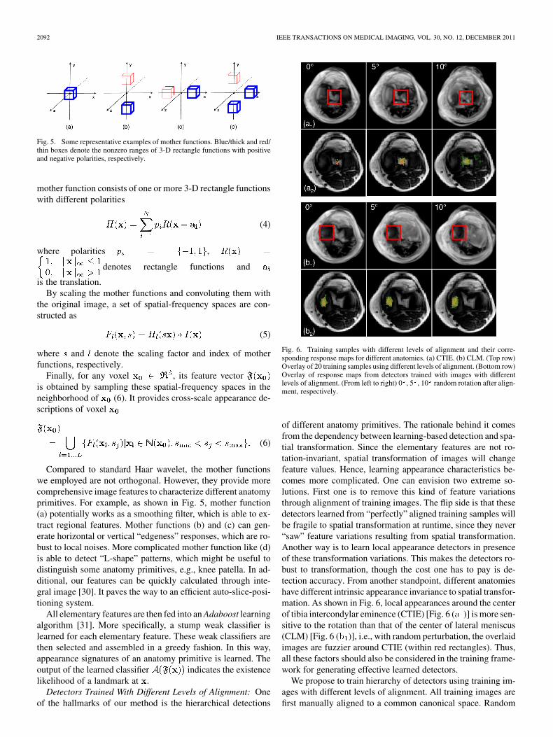
Fig. 5. Some representative examples of mother functions. Blue/thick and red/thin boxes denote the nonzero ranges of 3-D rectangle functions with positiveand negative polarities, respectively.
mother function consists of one or more 3-D rectangle functionswith different polarities
(4)
where polarities ,
denotes rectangle functions and
is the translation.By scaling the mother functions and convoluting them with
the original image, a set of spatial-frequency spaces are con-structed as
(5)
where and denote the scaling factor and index of motherfunctions, respectively.
Finally, for any voxel , its feature vectoris obtained by sampling these spatial-frequency spaces in theneighborhood of (6). It provides cross-scale appearance de-scriptions of voxel
(6)
Compared to standard Haar wavelet, the mother functionswe employed are not orthogonal. However, they provide morecomprehensive image features to characterize different anatomyprimitives. For example, as shown in Fig. 5, mother function(a) potentially works as a smoothing filter, which is able to ex-tract regional features. Mother functions (b) and (c) can gen-erate horizontal or vertical “edgeness” responses, which are ro-bust to local noises. More complicated mother function like (d)is able to detect “L-shape” patterns, which might be useful todistinguish some anatomy primitives, e.g., knee patella. In ad-ditional, our features can be quickly calculated through inte-gral image [30]. It paves the way to an efficient auto-slice-posi-tioning system.
All elementary features are then fed into an Adaboost learningalgorithm [31]. More specifically, a stump weak classifier islearned for each elementary feature. These weak classifiers arethen selected and assembled in a greedy fashion. In this way,appearance signatures of an anatomy primitive is learned. Theoutput of the learned classifier indicates the existencelikelihood of a landmark at .
Detectors Trained With Different Levels of Alignment: Oneof the hallmarks of our method is the hierarchical detections
Fig. 6. Training samples with different levels of alignment and their corre-sponding response maps for different anatomies. (a) CTIE. (b) CLM. (Top row)Overlay of 20 training samples using different levels of alignment. (Bottom row)Overlay of response maps from detectors trained with images with differentlevels of alignment. (From left to right) 0 , 5 , 10 random rotation after align-ment, respectively.
of different anatomy primitives. The rationale behind it comesfrom the dependency between learning-based detection and spa-tial transformation. Since the elementary features are not ro-tation-invariant, spatial transformation of images will changefeature values. Hence, learning appearance characteristics be-comes more complicated. One can envision two extreme so-lutions. First one is to remove this kind of feature variationsthrough alignment of training images. The flip side is that thesedetectors learned from “perfectly” aligned training samples willbe fragile to spatial transformation at runtime, since they never“saw” feature variations resulting from spatial transformation.Another way is to learn local appearance detectors in presenceof these transformation variations. This makes the detectors ro-bust to transformation, though the cost one has to pay is de-tection accuracy. From another standpoint, different anatomieshave different intrinsic appearance invariance to spatial transfor-mation. As shown in Fig. 6, local appearances around the centerof tibia intercondylar eminence (CTIE) [Fig. 6 ( )] is more sen-sitive to the rotation than that of the center of lateral meniscus(CLM) [Fig. 6 ( )], i.e., with random perturbation, the overlaidimages are fuzzier around CTIE (within red rectangles). Thus,all these factors should also be considered in the training frame-work for generating effective learned detectors.
We propose to train hierarchy of detectors using training im-ages with different levels of alignment. All training images arefirst manually aligned to a common canonical space. Random
ZHAN et al.: ROBUST AUTOMATIC KNEE MR SLICE POSITIONING THROUGH REDUNDANT AND HIERARCHICAL ANATOMY DETECTION 2093
rigid perturbations are then applied to these aligned training im-ages for feature extraction. Assume is the alignment matrixthat brings a training image to the canonical space, after ap-plying random rigid perturbation (where defines therandom perturbation range), the spatial-frequency spaces in (5)is reformulated as
(7)
where is the rigid transformation operator. Elementary fea-tures are then sampled in as (6) and used to traina detector.
By changing the random perturbation range , for the sameanatomy, we can train a set of detectors with different transfor-mation sensitivity as , whereindicates different random perturbation range and
. Finally, in (3) is defined by the inte-gration the responses of these detectors across all anatomy prim-itives as
(8)
Here, denotes the detector corresponding to the thanatomy primitive and trained by samples with random pertur-bation range . is a diagonal element of selection matrix
, corresponding to the th anatomy primitive.Fig. 6 ( and ) shows two interesting characteristics of
detectors trained with different levels of alignment. First, de-tectors trained with looser alignment (larger perturbation) showflatter response maps, while detectors trained with more rig-orous alignment (less perturbation) are more discriminative andprovide peaky response maps. Second, different anatomies havedifferent intrinsic invariance to spatial transformation. As shownin Fig. 6 , responses from CLM detectors display similarpatterns with respect to different levels of random perturbation.On the contrary, responses from CTIE detectors [Fig. 6 ]changes from a clear peaky pattern to a noisy flatter patternalong with looser alignment. These two characteristics provethe importance of using a “hierarchical” detection scheme toachieve both robustness and accuracy. It is realized in our itera-tive optimization framework (see details in Section III-D).
C. Distributed Anatomy Models
Learning-based detections are robust to reasonable appear-ance variations. However, imaging artifacts, severe diseases andvariations of field of views (FOV) can change local appear-ance dramatically causing erroneous detections. Hence, it is im-portant to prune these erroneous detections by exploiting spa-tial correlations between different anatomy primitives [role of
in (3)]. Indeed, “redundant” detections are only effectiveafter incorporating with spatial models of multiple anatomies.
Different from the active shape model that learns globalshape statistics, we propose to learn distributed anatomymodels, i.e., for each anatomy , we aim to learn its spatialrelations with other anatomies in a group-wise fashion. Assume
is the anatomy under study, is a subset of anatomy
primitives which does not contain , i.e., .The group-wise spatial configuration between andis modeled as a conditional probability following multi-variantGaussian distribution
(9)
where and are two statistical coefficients that are learned asfollows.
We employ a linear model to capture the spatial correlationbetween and as
(10)
where is a vector concatenated by anddenotes the linear correlation matrix. Given a set of training
samples, can be learned by solving a least squares problem.Furthermore, and are calculated as
(11)
In this way, each anatomy primitive receives a set of con-ditional probabilities from different subsets of
defined as (9). It is worth noting that a correctly de-tected might receive a lower conditional probability from asubset that includes erroneous detections. On the otherhand, in most cases, the conditional probabilities received byan erroneously detected are all low. (The only exception isthat the erroneous detections happen to construct a correct spa-tial configuration, which very rarely happens.) Therefore, themaximum value of all conditional probabilities received byis used to measure the “eligibility” of the spatial location of the
. in (3) is thus defined as
(12)
where is used to constrain the cardinality of .The advantage of our spatial correlation modeling is twofold.
First, instead of learning global spatial statistics, we learn spatialcorrelations within small groups of anatomies. At run-time, the“decisions” from these distributed models are assembled in a“democratic” way. It makes our method robust to missing orgross detection failures. Second, by constraining the cardinalityof and using a linear model, our spatial model will not overfiterroneous detections. The run-time efficiency of our auto-slice-positioning system is also guaranteed in this way.
D. Hierarchical Detection and Alignment
After incorporating (8) and (12), the objective function (3)becomes high-dimensional, nonlinear and nonconvex, which isdifficult to be optimized by traditional approaches. Recall (3), ithas three sets of optimization variables and , where isthe transformation parameters to be estimated and and aretwo sets of latent variables. This structure is similar to the max-imum-likelihood estimation problem, which is often tackledusing expectation-maximization (EM) algorithm. Thereby, our
2094 IEEE TRANSACTIONS ON MEDICAL IMAGING, VOL. 30, NO. 12, DECEMBER 2011
approach optimizes and iteratively following the idea ofan EM algorithm. The initial is set as an identity matrices.Afterwards, “expectation stage” (E-stage) and “maximizationstage” (M-stage) are performed iteratively until convergence.
E-Stage: During E-stage, we aim to optimize the two latentvariables and . is first optimized by maximizing
in (3). It is realized by invoking learned anatomy detec-tors on the image with current transformation, i.e., , togenerate response maps corresponding to different anatomies.The maximum positions of these response maps are consideredas intermediately optimized . By setting for withlow response and otherwise, we obtain the initial ,which is further optimized according to (12). This optimizationis performed by iteratively “peeling away” detections that “vi-olate” learned spatial statistics. For each iteration, we calculatethe minimum value of across allwith . If this value is less than a preset threshold , thecorresponding will be considered as an erroneous detectionand its corresponding is set as zero. This process is repeateduntil converges, i.e., no more landmarks are removed as er-roneous detection. After each E-stage, we get intermediate op-timization results and , which will be used in M-stage.
M-Stage: In M-stage, the intermediate optimized and arefixed. The rigid transformation is optimized using the close-form solution proposed in [32]. The derived transformationwill be considered as intermediately optimized transformationand used in the next E-stage.
During the iterative EM process, hierarchical detectionsand alignment are implicitly realized. As introduced inSection III-B, a hierarchy of detectors are built for eachanatomy primitive. In the initial stages, when the image is farfrom the well aligned position, detectors with looser alignment(more perturbations) often exhibit high responses and domi-nate [see (8)]. Along with the iterations, whenthe image is closer to a well aligned position, detectors withmore rigorous alignment start to generate higher responsesand thereby contribute more to . From anotherperspective, different anatomies have different intrinsic in-variance with respect to spatial transformation (as shown inFig. 6). Therefore, in the initial iterations, since anatomies withmore invariance, e.g.,CLM, have high detector responses thanthe others, e.g., CTIE, they are more likely to be selected foralignment. With the iterations, as the image becomes betteraligned, transformation-sensitive anatomies start to show higherdetector responses and they are thus highly likely to be selectedfor alignment. In this way, hierarchial detection and alignmentare naturally performed, which guarantees the robustness andaccuracy of our auto-slice positioning system.
IV. EXPERIMENTS
In clinical workflow, our auto-slice-positioning is employedto generate various high-res slice groups relevant to differentparts of knee joint, e.g., meniscus, patella, posterior cruciate lig-ament, etc. In this section, we will present experimental resultson three of them: knee meniscus, femur cartilage, and patellacartilage, whose detailed definitions are shown in Table I andFig. 1(b) and Fig. 7. As these three slice groups are frequentlyused in high-res knee MR scanning and relevant to different
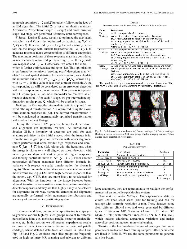
TABLE IDEFINITIONS OF THE POSITIONING OF KNEE MR SLICE GROUPS
Fig. 7. Definitions knee slice boxes. (a) Femur cartilage. (b) Patella cartilage.Rectangle boxes: coverage of MR slice group. Circles: imaging centers. Yellowdashed lines: orientation references.
TABLE IIPARAMETER SETTINGS
knee anatomies, they are representative to validate the perfor-mances of an auto-slice-positioning system.
Data and Parameter Settings: Our experimental data in-cludes 924 knee scout scans (180 for training and 744 fortesting) with isotropic resolution 2 mm. These datasets comefrom different clinical sites and were generated by differenttypes of Siemens MR Scanners (Avanto 1.5T, Verio 3T,Skyra 3T, etc.) with different knee coils (KN, K15, EX, etc.),which induces additional appearance variations and makesauto-slice-positioning even more challenging.
Thanks to the learning-based nature of our algorithm, mostparameters are learned from training samples. Other parametersare listed in Table II. We use the same parameters to generateall slice boxes.
ZHAN et al.: ROBUST AUTOMATIC KNEE MR SLICE POSITIONING THROUGH REDUNDANT AND HIERARCHICAL ANATOMY DETECTION 2095
Methods for Comparisons: As discussed in Section II, theauto-slice-positioning of knee scout scans can be realized usingdifferent state-of-art methods, e.g., detection and registration.We compare our method with four other representative ones. Tofacilitate the descriptions in the remainder of this section, wedefine acronyms of the methods for comparisons as follows.
• GReg: A global mutual information-based registrationmethod. A scout scan with normal knee appearance, shapeand size is selected as the model scan, in which the slicegroups are carefully positioned by a well-trained profes-sional. The test scout scan is registered to the model scoutscan using [6] implemented in ITK.
• LReg: A local mutual information-based registrationmethod. In this method, a local region-of-interest (ROI) isfirstly detected from the test scout scan to cover relevantanatomies. (To simply the implementation, slice groupcenters derived by our auto-slice-positioning algorithmare used as ROI centers. Since our auto-slice-positioningalgorithm is very robust, we only correct one case afterchecking the results. By setting the ROI size as 1.3 timesas the slice group size, relevant anatomies are ensured tobe contained in the ROI.) This ROI is then registered withthe corresponding ROI of a model scout scan using [6]implemented in ITK. Afterward, slice groups are derivedby applying the estimated rigid transformation to the entirescout scan.
• LHDet: A learning-based hierarchical detection method.Similar to our method, a hierarchy of detectors is trained onimages with different levels of alignment. These detectorsare invoked in an iterative detection and alignment frame-work. However, no redundant detections and group-wisespatial configurations are used in this method. In otherwords, in (3) is omitted.
• LRDet: A learning-based detection method with redun-dant detections and group-wise spatial configurations.However, no iterative alignment/detection is performed.Thus there are no hierarchical anatomy detections. In thisscenario, (8) only includes responses of detectors trainedby samples without alignment.
• LRHDet: Our auto-slice-positioning method, whichis based on redundant and hierarchial learning-baseddetections.
GReg and LReg demonstrate the performance of voxel-basedregistration methods on our problem. Comparisons of LHDetand LRDet with our proposed method LRHDet show the im-portance of redundant and hierarchical detections respectively.All these methods are validated in three aspects, robustness, ac-curacy and reproducibility.
A. Robustness
In this experiment, we validate the robustness of differentmethods on 744 knee scout scans. The slice positioning resultsare visually checked and evaluated by two experienced profes-sionals1 as “accurate (AC)”: accurate positioning that is accept-able by technicians, “reasonable (RE)”: reasonable good posi-tioning but still has the space to improve, and “gross failure
1Comparison methods are not blind to professionals.
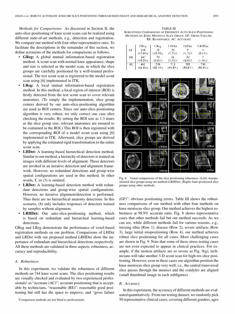
TABLE IIIROBUSTNESS COMPARISONS OF DIFFERENT AUTO-SLICE-POSITIONING
METHODS ON KNEE MENISCUS SLICE GROUP. GF: GROSS FAILURE.RE: REASONABLE. AC: ACCURATE
Fig. 8. Visual comparisons of the slice positioning robustness. (Left) Autopo-sitioned slice groups using our method (LRHDet). (Right) Auto-positioned slicegroups using other methods.
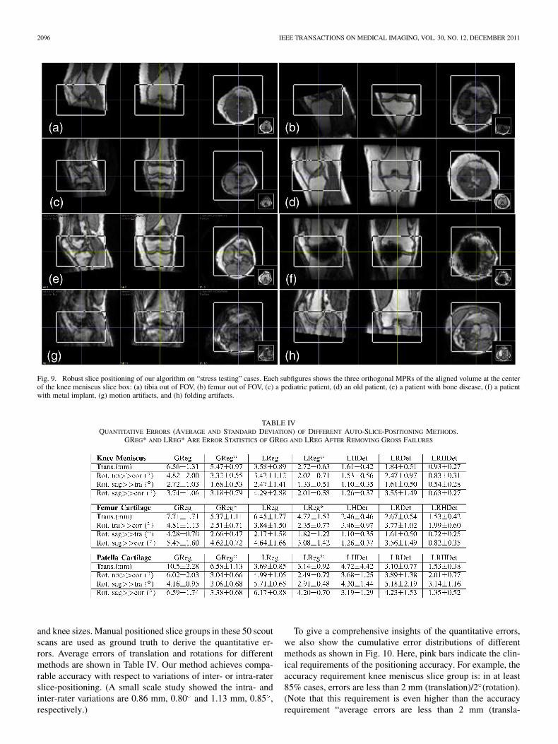
(GF)”: obvious positioning errors. Table III shows the robust-ness comparisons of our method with other four methods onknee meniscus slice group. Our method achieves the highest ro-bustness at 98.9% accurate ratio. Fig. 8 shows representativecases that other methods fail but our method succeeds. As wecan see, while different methods fail for various reasons, e.g.,missing tibia (Row 1). disease (Row 2), severe artifacts (Row3), large initial mispositioning (Row 4), our method achievesrobust slice positioning for all cases. More challenging casesare shown in Fig. 9. Note that some of these stress testing casesare not even expected to appear in clinical practices. For ex-ample, if the motion artifacts are so severe as Fig. 9(g), tech-nicians will take another 3-D scout scan for high-res slice posi-tioning. However, even in these cases our algorithm position theknee meniscus slice group very well, i.e., the central transversalslice passes through the menisci and the condyles are aligned(small thumbnail image in each subfigures).
B. Accuracy
In this experiment, the accuracy of different methods are eval-uated quantitatively. From our testing dataset, we randomly pick50 representative clinical cases, covering different genders, ages
2096 IEEE TRANSACTIONS ON MEDICAL IMAGING, VOL. 30, NO. 12, DECEMBER 2011
Fig. 9. Robust slice positioning of our algorithm on “stress testing” cases. Each subfigures shows the three orthogonal MPRs of the aligned volume at the centerof the knee meniscus slice box: (a) tibia out of FOV, (b) femur out of FOV, (c) a pediatric patient, (d) an old patient, (e) a patient with bone disease, (f) a patientwith metal implant, (g) motion artifacts, and (h) folding artifacts.
TABLE IVQUANTITATIVE ERRORS (AVERAGE AND STANDARD DEVIATION) OF DIFFERENT AUTO-SLICE-POSITIONING METHODS.
GREG* AND LREG* ARE ERROR STATISTICS OF GREG AND LREG AFTER REMOVING GROSS FAILURES
and knee sizes. Manual positioned slice groups in these 50 scoutscans are used as ground truth to derive the quantitative er-rors. Average errors of translation and rotations for differentmethods are shown in Table IV. Our method achieves compa-rable accuracy with respect to variations of inter- or intra-raterslice-positioning. (A small scale study showed the intra- andinter-rater variations are 0.86 mm, 0.80 and 1.13 mm, 0.85 ,respectively.)
To give a comprehensive insights of the quantitative errors,we also show the cumulative error distributions of differentmethods as shown in Fig. 10. Here, pink bars indicate the clin-ical requirements of the positioning accuracy. For example, theaccuracy requirement knee meniscus slice group is: in at least85% cases, errors are less than 2 mm (translation)/2 (rotation).(Note that this requirement is even higher than the accuracyrequirement “average errors are less than 2 mm (transla-
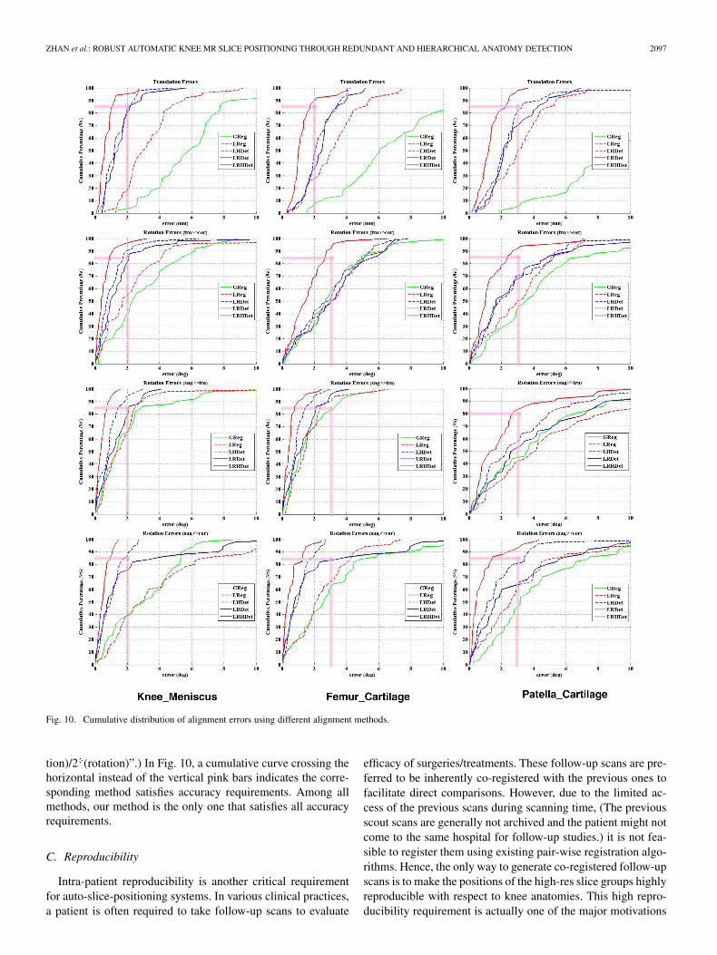
ZHAN et al.: ROBUST AUTOMATIC KNEE MR SLICE POSITIONING THROUGH REDUNDANT AND HIERARCHICAL ANATOMY DETECTION 2097
Fig. 10. Cumulative distribution of alignment errors using different alignment methods.
tion)/2 (rotation)”.) In Fig. 10, a cumulative curve crossing thehorizontal instead of the vertical pink bars indicates the corre-sponding method satisfies accuracy requirements. Among allmethods, our method is the only one that satisfies all accuracyrequirements.
C. Reproducibility
Intra-patient reproducibility is another critical requirementfor auto-slice-positioning systems. In various clinical practices,a patient is often required to take follow-up scans to evaluate
efficacy of surgeries/treatments. These follow-up scans are pre-ferred to be inherently co-registered with the previous ones tofacilitate direct comparisons. However, due to the limited ac-cess of the previous scans during scanning time, (The previousscout scans are generally not archived and the patient might notcome to the same hospital for follow-up studies.) it is not fea-sible to register them using existing pair-wise registration algo-rithms. Hence, the only way to generate co-registered follow-upscans is to make the positions of the high-res slice groups highlyreproducible with respect to knee anatomies. This high repro-ducibility requirement is actually one of the major motivations
2098 IEEE TRANSACTIONS ON MEDICAL IMAGING, VOL. 30, NO. 12, DECEMBER 2011
Fig. 11. (a) Schematic explanation of synthetic reproducibility test. (b) ROIsof knee meniscus, femur cartilage, and patella cartilage.
to develop an auto-slice-positioning system. In this section, wewill validate the reproducibility of our method using syntheticand real re-scan datasets.
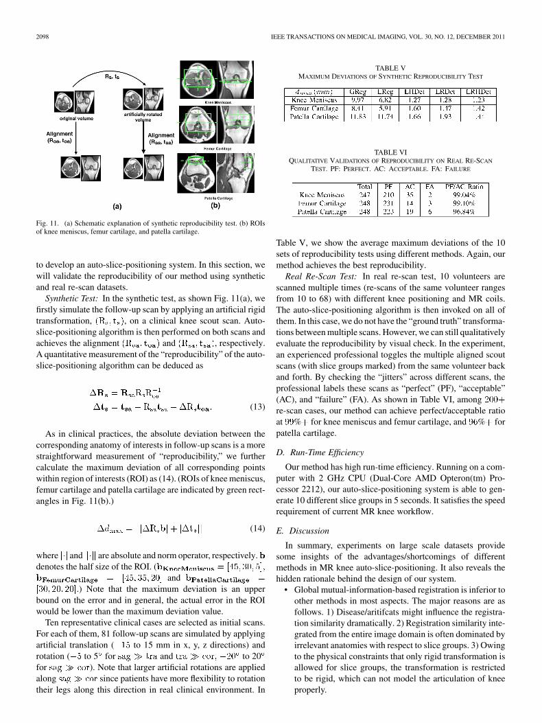
Synthetic Test: In the synthetic test, as shown Fig. 11(a), wefirstly simulate the follow-up scan by applying an artificial rigidtransformation, , on a clinical knee scout scan. Auto-slice-positioning algorithm is then performed on both scans andachieves the alignment and , respectively.A quantitative measurement of the “reproducibility” of the auto-slice-positioning algorithm can be deduced as
(13)
As in clinical practices, the absolute deviation between thecorresponding anatomy of interests in follow-up scans is a morestraightforward measurement of “reproducibility,” we furthercalculate the maximum deviation of all corresponding pointswithin region of interests (ROI) as (14). (ROIs of knee meniscus,femur cartilage and patella cartilage are indicated by green rect-angles in Fig. 11(b).)
(14)
where and are absolute and norm operator, respectively.denotes the half size of the ROI. (
and.) Note that the maximum deviation is an upper
bound on the error and in general, the actual error in the ROIwould be lower than the maximum deviation value.
Ten representative clinical cases are selected as initial scans.For each of them, 81 follow-up scans are simulated by applyingartificial translation ( to 15 mm in x, y, z directions) androtation ( to 5 for and to 20for ). Note that larger artificial rotations are appliedalong since patients have more flexibility to rotationtheir legs along this direction in real clinical environment. In
TABLE VMAXIMUM DEVIATIONS OF SYNTHETIC REPRODUCIBILITY TEST
TABLE VIQUALITATIVE VALIDATIONS OF REPRODUCIBILITY ON REAL RE-SCAN
TEST. PF: PERFECT. AC: ACCEPTABLE. FA: FAILURE
Table V, we show the average maximum deviations of the 10sets of reproducibility tests using different methods. Again, ourmethod achieves the best reproducibility.
Real Re-Scan Test: In real re-scan test, 10 volunteers arescanned multiple times (re-scans of the same volunteer rangesfrom 10 to 68) with different knee positioning and MR coils.The auto-slice-positioning algorithm is then invoked on all ofthem. In this case, we do not have the “ground truth” transforma-tions between multiple scans. However, we can still qualitativelyevaluate the reproducibility by visual check. In the experiment,an experienced professional toggles the multiple aligned scoutscans (with slice groups marked) from the same volunteer backand forth. By checking the “jitters” across different scans, theprofessional labels these scans as “perfect” (PF), “acceptable”(AC), and “failure” (FA). As shown in Table VI, amongre-scan cases, our method can achieve perfect/acceptable ratioat % for knee meniscus and femur cartilage, and % forpatella cartilage.
D. Run-Time Efficiency
Our method has high run-time efficiency. Running on a com-puter with 2 GHz CPU (Dual-Core AMD Opteron(tm) Pro-cessor 2212), our auto-slice-positioning system is able to gen-erate 10 different slice groups in 5 seconds. It satisfies the speedrequirement of current MR knee workflow.
E. Discussion
In summary, experiments on large scale datasets providesome insights of the advantages/shortcomings of differentmethods in MR knee auto-slice-positioning. It also reveals thehidden rationale behind the design of our system.
• Global mutual-information-based registration is inferior toother methods in most aspects. The major reasons are asfollows. 1) Disease/aritifcats might influence the registra-tion similarity dramatically. 2) Registration similarity inte-grated from the entire image domain is often dominated byirrelevant anatomies with respect to slice groups. 3) Owingto the physical constraints that only rigid transformation isallowed for slice groups, the transformation is restrictedto be rigid, which can not model the articulation of kneeproperly.
ZHAN et al.: ROBUST AUTOMATIC KNEE MR SLICE POSITIONING THROUGH REDUNDANT AND HIERARCHICAL ANATOMY DETECTION 2099
• Local mutual-information-based registration achievesbetter performance than the global one due to its focuseson local relevant anatomies. However, it is not robust tolarger variations owing to different ages, patient sizes,diseases, and imaging artifacts.
• Learning-based detection method opens the window to ex-tract local appearance cues in a more robust way. However,redundant and hierarchical detections should be performedto satisfy the high robustness and accuracy requirementsfrom clinical practices.
• Redundant and hierarchical detections benefit theauto-slice-positioning system from different perspec-tives. Redundancy (LRDet method) helps more in theimprovement of robustness, which is shown as less grossfailure in Table III. On the contrary, hierarchy (LHDet)improves the accuracy and provides more accurate posi-tioning in Table III. This situation is also shown in theplots of quantitative accuracy (Fig. 10).
• Overall, our method that incorporates both redundantand hierarchical learning-based detections achieves thebest performance in terms of robustness, accuracy, andreproducibility. In our comparison study, it is the only onethat satisfies the high performance requirements.
V. CONCLUSION AND FUTURE WORK
In this paper, we proposed an auto-slice-positioning methodfor 3-D MR knee scout scans. To address various challengescoming from MR scout scans, we design an auto-slice-posi-tioning system using redundant and hierarchical learning-basedanatomy detections. Thus, our method becomes highly robust,accurate, reproducible, and fast with extensive demonstration on744 dataset. The proposed method paves the way to automatethe positioning of slice boxes for high-res MR knee scanningand improve the MR knee workflow efficacy. We expect withtime as this technology is adapted more often in the MR kneescanning workflow, more clinical studies will be carried out toevaluate the added clinical value.
The potential of the proposed algorithm reaches beyond MRknee scout scans. In the future, with the development of fast MRimaging technologies, 3-D diagnostic scan with isotropic highresolution might be available. It will significantly improve MRknee workflow since different knee anatomies can be scannedin one shot. However, due to the large data volume in 3-D di-agnostic scans, it will take more time for a radiologist to navi-gate through a large number of slices and find the appropriateslices/orientations for diagnosis. By adapting the auto-slice-po-sitioning algorithm to 3-D diagnostic scan, we can improve thereading speed and render the anatomy of interests to radiologistsin a more accurate and reproducible way.
In the future, we plan to extend our auto-slice-positioning al-gorithm to adapt slice group sizes according to real anatomysizes. In this way, the coverage of high-res slice boxes can beoptimally utilized. Another interesting topic relates to the se-lection matrix in (3). Instead of restricting its entries as 0/1,these variables can be relaxed to 0–1. In this way, selected land-marks will have different contributions to the alignment. It is
interesting to investigate if a soft/fuzzy selection matrix willfurther improve the algorithm performance.
REFERENCES
[1] T. Benner, J. Wisco, A. van der Kouwe, B. Fischl, M. Vangel, F.Hochberg, and A. Sorensen, “Comparison of manual and automaticsection positioning of brain MR images,” Radiology, vol. 239, pp.246–254, 2006.
[2] F. E. Lecouvet, J. Claus, P. Schmitz, V. Denolin, C. Bos, and B. C. Van-deBerg, “Clinical evaluation of automated scan prescription of kneeMR images,” Journal of Mag. Res. Imag., vol. 29, 2009.
[3] S. Ostlere, “Imaging the knee,” Imaging, vol. 15, pp. 217–241, 2007.[4] J. van der Kouwe, T. Benner, B. Fischl, F. Schmitt, D. H. Salat, M.
Harder, A. G. Sorensen, and A. M. Dale, “On-line automatic slice po-sitioning for brain MR imaging,” NeuroImage, vol. 27, pp. 222–230,2005.
[5] D. Bystrov, V. Pekar, and S. Young, “Automated planning of MRI scansof knee joints,” in SPIE 2007, San Diego, CA, 2007, pp. 601–608.
[6] J. Hajnal, D. J. Hawkes, and D. Hill, Medical Image Registration.Boca Raton, FL: CRC Press, 2001.
[7] P. Viola and M. J. Jones, “Robust real-time face detection,” Int. J.Comput. Vis., vol. 57, pp. 137–154, 2004.
[8] M. Jolly et al., “Automatic femur segmentation and condyle line de-tection in 3-D MR scans for laignment of high resolution MR,” in ISBI2010, Rotterdam, The Netherlands, 2010, pp. 940–943.
[9] A. Toga and P. Thompson, “The role of image registration in brainmapping,” Image Vis. Comput., vol. 19, pp. 3–24, 2001.
[10] T. Makela, P. Clarysse, O. Sipila, N. Pauna, Q. C. Pham, T. Katila, andI. Magnin, “A review of cardiac image registration methods,” IEEETrans. Med. Image, vol. 21, no. 9, pp. 1011–1021, Sep. 2002.
[11] Y. Zhan, D. Shen, and R. Taylor, “Deformable registration of malepelvises in CT images,” in ISBI 2004, Arlington, VA, 2004, pp.1463–1466.
[12] Y. Zhan, Y. Ou, M. Feldman, J. Tomaszeweski, C. Davatzikos, and D.Shen, “Registering histological and MR images of prostate for image-based cancer detection,” Acad. Radiol., vol. 14, pp. 1367–1381, 2007.
[13] W. Wells, P. Viola, H. Atsumid, S. Nakajimae, and R. Kikinis, “Multi-modal volume registration by maximization of mutual information,”Med. Image Anal., vol. 1, pp. 35–51, 1996.
[14] B. Glocker, N. Komodakis, G. Tziritas, N. Navab, and N. Paragios,“Dense image registration through MRFS and efficient linear program-ming,” Med. Image Anal., vol. 12, pp. 731–741, 2008.
[15] D. Shen and C. Davatzikos, “Hammer: Hierarchical attribute matchingmechanism for elastic registration,” IEEE Trans. Medical Imaging, vol.21, 2002.
[16] K. Rohr, H. Stiehl, R. Sprengel, T. Buzug, J. Weese, and M. Kuhn,“Landmark-based elastic registration using approximating thin-platesplines,” IEEE Trans. Med. Imag., vol. 20, no. 6, pp. 526–534, Jun.2001.
[17] A. Joshi, D. Shattuck, P. Thompson, and R. Leahy, “Surface-con-strained volumetric brain registration using harmonic mappings,”IEEE Trans. Med. Imag., vol. 26, no. 12, pp. 1657–1669, Dec. 2007.
[18] C. Davatzikos, J. Prince, and R. Bryan, “Image registration basedon boundary mapping,” IEEE Trans. Med. Imag., vol. 15, no. 1, pp.112–115, Feb. 1996.
[19] X. Pennec, N. Ayache, and J.-P. Thirion, Landmark-Based RegistrationUsing Features Identified Through Differential Geometry. New York:Academic, 2008.
[20] H. Grabnera, T. Nguyena, B. Gruberb, and H. Bischofa, “On-lineboosting-based car detection from aerial images,” J. PhotogrammetryRemote Sensing, vol. 63, pp. 87–95, 2008.
[21] O. Tuzel, F. Porikli, and P. Meer, “Pedestrian detection via classifica-tion on riemannian manifolds,” IEEE Trans. Pattern Anal. Mach. In-tell., vol. 30, pp. 1713–1727, 2008.
[22] H. Schneiderman and T. Kanade, “A statistical method for 3-D objectdetection applied to faces and cars,” in CVPR 2000, Hilton Head, SC,2000, pp. 746–751.
[23] X. Lv, J. Zhou, and C. Zhang, “A novel algorithm for rotated humanface detection,” in CVPR 2000, Hilton Head, SC, 2000, pp. 760–765.
[24] H. Rowley, S. Baluja, and T. Kanade, “Neural network-based face de-tection,” IEEE Trans. Pattern Anal. Mach. Intell., vol. 20, no. 1, pp.23–38, Jan. 2001.

2100 IEEE TRANSACTIONS ON MEDICAL IMAGING, VOL. 30, NO. 12, DECEMBER 2011
[25] C. Huang, H. Ai, Y. Li, and S. Lao, “Vector boosting for rotation in-variant multi-view face detection,” in ICCV 2005, Beijing, China, 2005,pp. 446–453.
[26] B. Heisele, P. Ho, and T. Poggio, “Face recognition with support vectormachines: Global versus component-based approach,” in ICCV 2001,Vancouver, Canada, 2001, pp. 688–694.
[27] M. Osadchy, Y. Cun, and M. L. Miller, “Synergistic face detection andpose estimation with energy-based models,” J. Mach. Learn. Res., vol.8, pp. 1197–1215, 2007.
[28] Y. Zheng, A. Barbu, B. Georgescu, M. Scheuering, and D. Comaniciu,“Four-chamber heart modeling and automatic segmentation for 3-D car-diac CT volumes using marginal space learning and steerable features,”IEEE Trans. Med. Imag., vol. 27, no. 11, pp. 1668–1681, Nov. 2008.
[29] X. S. Zhou, Z. Peng, Y. Zhan, M. Dewan, B. Jian, A. Krishnan,Y. Tao, M. Harder, S. Grosskopf, and U. Feuerlein, “Redundancy,redundancy, redundancy: The three keys to highly robust anatomicalparsing in medical images,” in Multimedia Inf. Retrieval, 2010, pp.175–184.
[30] F. Crow, “Summed-area tables for texture mapping,” in SIGGRAPH,1984, vol. 18, no. 3, pp. 208–212.
[31] Y. Freund and R. E. Schapire, “A decision-theoretic generalization ofon-line learning and an application to boosting,” J. Comput. Syst. Sci.,vol. 55, pp. 119–139, 1997.
[32] D. Eggert, A. Lorusso, and R. Fisher, “Estimating 3-D rigid body trans-formations: A comparison of four major algorithms,” Mach. Vis. Appl.,vol. 9, pp. 272–290, 1997.
Related Documents