NEW 200 6 CATALOG Robotic/Automatic Tool Changer For Heavy Automation

Welcome message from author
This document is posted to help you gain knowledge. Please leave a comment to let me know what you think about it! Share it to your friends and learn new things together.
Transcript
NEW 2006 CATALOG
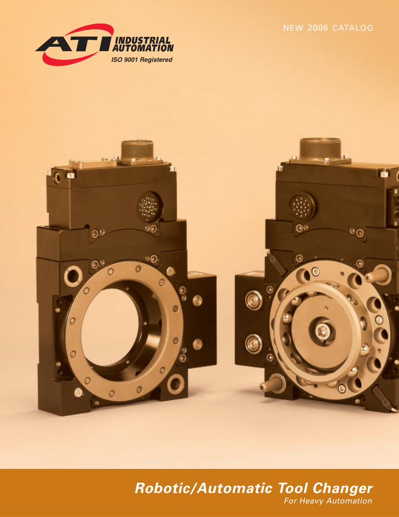
Robotic/Automatic Tool ChangerFor Heavy Automation

High-flow fluid module: The Fluid/Air module has a Cv of 1.65 (1.65 gallons of water per minute for 1 psipressure drop) allowing for better weld gun and transformer cooling.
Product Enhancements
Our staff of engineers and designers have made manydesign improvements that enhance the performanceand functionality of these Tool Changer models.
Common Accessory Module Mounting: Modulesmount from the Tool Changer face to provide extra support for applications with heavy dress packages. All modules use a common mounting pattern so they canbe swapped between the QC-210, QC-310 and QC-510models and located on any of three available flats.
In-the-Body Sensing: Lock/Unlock/Ready-to-Lock sensors have been integrated into the body of the ToolChanger. This design provides the advantages of reducedstack height and reduced weight without sacrificing thestrength of the unit. Two Ready-to-Lock sensors in thebody affords the robot programmer the ability to betterteach Master-to-Tool coupling.
High Strength: Design improvements to the alignmentpins and bushings have increased the moment capacityof both the QC-210 and QC-310.
Integrated Bolt Circle Patterns: Common, industry-standard bolt circle patterns have been integrateddirectly into the Tool Changer body of these models,often eliminating the need for an interface plate whichreduces stack height.
Robotic Tool Changers for HeavyAutomation
The Heavy Automation Robotic Tool Changer linehas been developed for the resistance welding marketand medium- to heavy-duty material handling. Becausethese Tool Changers use modules to pass utilities (e.g.water, electrical, pneumatic, etc.), they are able to han-dle numerous applications by simply selecting thedesired modules. These Tool Changers have extremelyhigh moment capacity for use in demanding applica-tions.
Product Advantages
Modular Design: Power, coolant, servo, DeviceNet™,and signal features are built into separate modulesmaking maintenance easy. Module housings use acommon mounting design for use on the QC-210, QC-310 and QC-510, increasing flexibility in configuring theTool Changer.
Extremely High Moment Capacity: Many Tool Changerswith high moment loads gap (separate between theMaster and Tool plates) during high-speed moves, causingdisruption to utilities such as servo lines. The HeavyAutomation series from ATI can take on dynamicmoment loads and maintain utility functions during fullrange of motion.
Integrated Solution for DeviceNet: The DeviceNetmodule supports an integrated valve that is internallyplumbed and interfaces with internal cable routing in theTool Changer body.
Easy Dress: The modules are designed to place electrical,pneumatic and water ports in-line, affording the customeran easy dress-out.
Battery Backup for Servo: The servo module has abattery backup option on the Tool side to allow the servoto hold information while disconnected from the robot.
Strong Power and Servo Module Housing: The primarycurrent and servo modules use an aluminum housing toprevent damage from cable stress and crashes.
Weight and Size Reduction: Weight and size are keptas small as possible without reducing reliability or performance.
No-Touch Contacts Increase Safety: 200-amp powerand signal modules have contacts that are not touchableon the Master side—increasing safety and world wideacceptance.
TOOL CHANGERS FOR HEAVY AUTOMATION
QC-210 Module to Body Connection
2 VISIT WWW.ATI-IA.COM FOR CURRENT PRODUCT SPECIFICATIONS, 2-D DRAWINGS, AND 3-D CAD MODELS

QC-210
Product Advantages
No-Touch Locking technology allows up to 2.5mm plate separation when locking.
Ready Sensors (2) detect when the Tool plate iswithin 1.5 mm of the Master plate, signaling ready-to-lock.
Patented Fail-safe locking mechanism
• Locking mechanism design results in low forceacting on the piston.
• Large piston diameter and outward ball travelincrease moment capacity.
• All locking parts are made of Rc58 stainless steel.
Integrated Lock/Unlock Sensing ProximitySensors to indicate Lock/Unlock position for safeCoupling/Uncoupling.
Mounts Directly to most 200 kg Robots
(no SIP plate required, see stack height below)
Robotic Tool Changer for Heavy
Automation
QC-210 with AA2 Pneumatic module and DH3/DH2InstaTool™ modules for DeviceNet
Specifications Values Comments
Suggested Payload Limit 496 lbs The mass attached to the Tool Changer. Higher payloads(225 kg) possible with moment rating.
Locking Force @ 80 psi 7000 lbs Axial holding force.(31,150 N)
Static Moment Capacity (X & Y) 24,000 in-lb Higher dynamic moment possible depending on module selection.(2700 Nm) Failure test exceeded 120,000 in-lb (13,560 Nm) moment.
Static Moment Capacity (Z) 20,000 in-lb (Torsion) Higher dynamic moment possible depending on module(2260 Nm) selection. Failure test exceeded 100,000 in-lb (11,300 Nm) moment.
Positional Repeatability (X,Y, & Z) 0.0006 in Repeatability tested at rated load at over one million cycles.(0.015 mm)
Weight (when coupled) 17.0 lbs Master: 11.6 lbs (5.3 kg) (no accessory modules) (7.7 kg) Tool: 5.4 lbs (2.4 kg)
Stack height when locked 3.43 in Stack height for 125 mm ISO pattern(103 mm)
4.06 in Stack height for 160 mm ISO pattern (includes IP)(120 mm)
Body size (no modules) 6.3 x 6.3 in Size of body prior to module mounting.(160x160 mm)
Maximum allowable distance between 0.1 in Normal recommended locking distance. Locking distance Master and Tool plates before locking (2.5 mm) varies depending on module selection, lock pressure, pay
load, etc.
Sensor Information, signal name L/U/RTL Lock/Unlock sensors (2) integrated into the body of the(Lock/Unlock/ Tool Changer. (2) Ready Sensors, 180 degrees apart,R1 and R2) afford easier teaching for the robot programmer.
VISIT WWW.ATI-IA.COM FOR CURRENT PRODUCT SPECIFICATIONS, 2-D DRAWINGS, AND 3-D CAD MODELS 3

QC-310
Product Advantages
No-Touch Locking technology allows up to 2.5mm plate separation when locking.
Ready Sensors (2) detect when the Tool plate iswithin 1.5 mm of the Master plate, signaling ready-to-lock.
Patented Fail-safe locking mechanism
• Locking mechanism design results in low forceacting on the piston.
• Large piston diameter and outward ball travelincrease moment capacity.
• All locking parts are made of Rc58 stainless steel.
Integrated Lock/Unlock Sensing ProximitySensors to indicate Lock/Unlock position for safeCoupling/Uncoupling.
Mounts Directly to most 500 kg Robots
(no SIP required; see stack height below)
Robotic Tool Changer for Heavy
Automation
Specifications Values Comments
Suggested Payload Limit 1120 lbs The mass attached to the Tool Changer. Higher payloads(500 kg) possible with moment rating.
Locking Force @ 80 psi 7940 lbs Axial holding force.(35,333 N)
Static Moment Capacity (X & Y) 29,100 lb-in Higher dynamic moment possible depending on module selection.(3870 Nm) Failure test exceeded 180,000 in-lb (20,340 Nm) moment.
Static Moment Capacity (Z) 28,000 lb-in (Torsion) Higher dynamic moment possible depending on module(3150 Nm) selection. Failure test exceeded 100,000 in-lb (11,300 Nm) moment.
Positional Repeatability (X,Y, & Z) .0006 in Repeatability tested at rated load at over one million cycles.(.015 mm)
Weight (when coupled) 44.0 lbs Master: 27.5 lbs (12.5 kg)(no accessory modules) (20.0 kg) Tool: 16.5 lbs (7.5 kg)
Stack height when locked 4.72 in Stack height - 200 mm ISO pattern(120.0 mm)
Body size (no modules) 9.6 x 9.6 in Size of body prior to module mounting.(244 x244 mm)
Maximum allowable distance between 0.1 in Normal recommended locking distance. Locking distance Master and Tool plates before locking (2.5 mm) varies depending on module selection, lock pressure, pay
load, etc.
Sensor Information, signal name L/U/RTL Lock/Unlock sensors (2) integrated into the body of the(Lock/Unlock/ Tool Changer. (2) Ready Sensors, 180 degrees apart,R1 and R2) afford easier teaching for the robot programmer.
QC-310 with AA2 Pneumatic module and DH3/DH2InstaTool modules for DeviceNet
4 VISIT WWW.ATI-IA.COM FOR CURRENT PRODUCT SPECIFICATIONS, 2-D DRAWINGS, AND 3-D CAD MODELS

Product Advantages
No-Touch Locking technology allows up to 2.5mm plate separation when locking.
Ready Sensors (2) detect when the Tool plate iswithin 1.5 mm of the Master plate, signaling ready-to-lock.
Patented Fail-safe locking mechanism
• Locking mechanism design results in low forceacting on the piston.
• Large piston diameter and outward ball travelincrease moment capacity.
• All locking parts are made of Rc58 stainless steel.
Integrated Lock/Unlock Sensing ProximitySensors to indicate Lock/Unlock position for safeCoupling/Uncoupling.
Mounts Directly to most 600+ kg Robots
(no SIP required; see stack height below)
QC-510
Robotic Tool Changer for Heavy
Automation
Specifications Values Comments
Suggested Payload Limit 1540 lbs The mass attached to the Tool Changer. Higher payloads(700 kg) possible with moment rating.
Locking Force @ 80 psi 14,000 lbs Axial holding force.(62,300 N)
Static Moment Capacity (X & Y) 43,000 lb-in Higher dynamic moment possible depending on module(4680 Nm) selection. Failure test exceeded 250,000 in-lb (28,250 Nm) moment .
Static Moment Capacity (Z) 31,000 lb-in (Torsion) Higher dynamic moment possible depending on module(3500 Nm) selection. Failure test exceeded 150,000 in-lb (16,950 Nm) moment.
Positional Repeatability (X,Y, & Z) .0006 in Repeatability tested at rated load at over one million cycles.(.015 mm)
Weight (when coupled) 61.7 lbs Master: 42.6 lbs (19.3 kg)(no accessory modules) (28.0 kg) Tool: 19.1 lbs (8.7 kg)
Stack height when locked 5.6 in Stack height - 200 mm ISO pattern (142 mm)
Body size (no modules) 10.4 x 10.4 in Size of body prior to module mounting.(264 x 264 mm)
Maximum allowable distance between 0.1 in Normal recommended locking distance. Locking distance Master and Tool plates before locking (2.5 mm) varies depending on module selection, lock pressure, pay
load, etc.
Sensor Information, signal name L/U/RTL Lock/Unlock sensors (2) integrated into the body of the(Lock/Unlock/ Tool Changer. (2) Ready Sensors, 180 degrees apart,R1 and R2) afford easier teaching for the robot programmer.
QC-510 with AA2 Pneumatic module and DH3/DH2InstaTool modules for DeviceNet
VISIT WWW.ATI-IA.COM FOR CURRENT PRODUCT SPECIFICATIONS, 2-D DRAWINGS, AND 3-D CAD MODELS 5
°03
:srebmuN traPGS-0-0-2AA-3HD2CJ-MB012-1219 :retsaM )A(
)A(
0-0-2AA-2HD-TC012-1219 :looT )B(
)B(
regnahC looT TPN 4/1ylppus ria kcolnU/kcoL
ecafretnI remotsuC
etalP
etalP
1.75
4.6
retsaM
ssoB
tiF pilS remotsuC
niP03
looT1.64
ecafretnI
08
delpuoC
]"60.4[2.301
)ylno noitcejorp(ediS looT
ecafretnI remotsuC.pD 81 ,57.1x21M deppaT )8(
:setoN,srotcennoC "elytS-iniM" dradnatS htiw emoc seludom teNeciveD ehT .1
remotsuc ot refeR .snoitacinummoC suB rof niP-5 dna rewoP yrailixuA rof niP-4 .noitamrofni gniriw rotcennoc cificeps rof seludom teNeciveD eht fo sgniward
.strop dekcehc TPN 2/1 )2( evah seludoM 2AA .2etacidni rebmun trap retsam no GS .3 .srosnes kcol-ot-ydaer & kcolnu/kcol PNP s
ecafretnI remotsuC
.pD 21remotsuC
.pD 02 ,)tiF pilS( 01
2.201
°03
,
seludoM
001decapS yllauqE
looT& retsaM
T-2HDeludoM
ecafretnI
.pD 02 ,)tiF pilS( 01
°03 )4(
°03 )4(
deppaT)6(.pD 5.1x01M
ecafretnI remotsuC.pD 8 ,7H
erauqS061
ecafretnI remotsuC
061.C.B
521
)2(
.C.B
02
ecafretnI remotsuCdecapS yllauqE
,)tiF pilS( 21
4.331M-3HD/T-2HD
6.11
.ytiralc rof nwohs ton selbac evlav dna tupni rosneS:etoN retsaM
)ylno noitcejorp(ediS retsaM
.pD 6.01 deroB'C )01(ediS raF morFSCHS 01M rofslewoD 01 pikS-gnicapS 03ecafretnI remotsuC
seludoM
22
M-3HD
521.C.B
601
seludoM
89
2AA
2AA
eludoM
2.83
.pD 21 ,)tiF pilS( 01)2(decapS yllauqE
ecafretnI remotsuC
3:1elacS
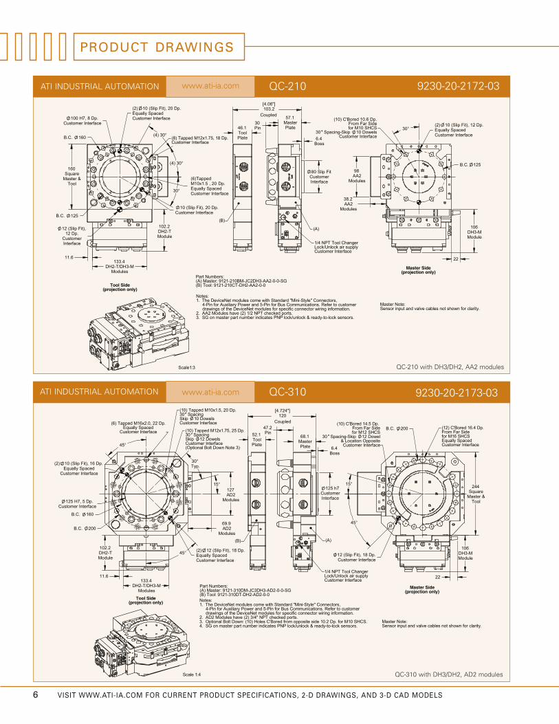
www.ati-ia.comATI INDUSTRIAL AUTOMATION QC-210 9230-20-2172-03
6 VISIT WWW.ATI-IA.COM FOR CURRENT PRODUCT SPECIFICATIONS, 2-D DRAWINGS, AND 3-D CAD MODELS
QC-210 with DH3/DH2, AA2 modules
PRODUCT DRAWINGS
ediS retsaM)ylno noitcejorp(
etisoppO noitacoL &ecafretnI remotsuC
.pD 4.61 deroB'C )21(
ecafretnI remotsuCdecapS yllauqE
SCHS 61M rofediS raF morF
.pD 5.41 deroB'C )01(ediS raF morFSCHS 21M roflewoD 21 pikS-gnicapS 03
:etoN retsaM.ytiralc rof nwohs ton selbac evlav dna tupni rosneS
looT
°51
& retsaM
.pD 81 ,)tiF pilS( 21
°54
erauqS
002
ecafretnI remotsuC eludoM
.C.B
442
601M-3HD
22
4:1 elacS
ediS looT)ylno noitcejorp(
)A(
ecafretnI remotsuC
.strop dekcehc TPN "4/3 )2( evah seludoM 2DA .2.SCHS 01M rof .pD 2.01 edis etisoppo morf deroB'C seloH )01( :nwoD tloB lanoitpO .3
etacidni rebmun trap retsam no GS .4 .srosnes kcol-ot-ydaer & kcolnu/kcol PNP s
:setoN,srotcennoC "elytS-iniM" dradnatS htiw emoc seludom teNeciveD ehT .1
remotsuc ot refeR .snoitacinummoC suB rof niP-5 dna rewoP yrailixuA rof niP-4 .noitamrofni gniriw rotcennoc cificeps rof seludom teNeciveD eht fo sgniward
regnahC looT TPN 4/1ylppus ria kcolnU/kcoL
)B(
looT1.25
2.74
etalP
niP
retsaMetalP 4.6
ssoB
remotsuC7h
1.86
ecafretnI
521
delpuoC
]"427.4[021
:srebmuN traPGS-0-0-2DA-3HD3CJ-MD013-1219 :retsaM )A(
0-0-2DA-2HD-TD013-1219 :looT )B(
slewoD 01 pikSecafretnI remotsuC
03
)3 etoN nwoD tloB lanoitpO(ecafretnI remotsuC slewoD 21 pikS
gnicapS .pD 52 ,57.1x21M deppaT )01(
.pD 02 ,5.1x01M deppaT )01(gnicapS 03
.pD 22 ,0.2x61M deppaT )6(decapS yllauqE
ecafretnI remotsuC
ecafretnI remotsuC
9.96
.pD 5 ,7H
4.331
eludoM
.C.B
002
M-3HD/T-2HD
2DA
°54
seludoM
ecafretnI remotsuCdecapS yllauqE
521
061
°54
°51
.C.B
21)2(
seludoM
.pD 81 ,)tiF pilS(
ecafretnI remotsuCdecapS yllauqE .pyT
721
°03.pD 61 ,)tiF pilS(
seludoM2DA
01)2(
2.201T-2HD
6.11
QC-310 with DH3/DH2, AD2 modules
www.ati-ia.comATI INDUSTRIAL AUTOMATION QC-310 9230-20-2173-03

002 .C.B
°51°03
).pyT(
°54
°51
°03).pyT(
002.C.B
°54
°51
°03).pyT(
.pD 92 ,57.1x21M deppaT )5( decapS yllauqE
)esiwkcolC retnuoC(
ecafretnI remotsuCdecapS yllauqE.pD 92 ,0.2x61M deppaT )21(
ecafretnI remotsuC
.pD 92 ,57.1x21M deppaT )5( decapS yllauqE
)esiwkcolC retnuoC(ecafretnI remotsuC
ecafretnI remotsuC
.pD 31 ,tiF pilS decapS yllauqE
ecafretnI remotsuC
seludoM
2.201
.pD 5.6 ,7H 521
eludoMT-2HD
21)2(
4.331M-3HD/T-2HD
6.11
)B(
ecafretnI remotsuC
regnahC looT TPN 4/1ylppuS riA kcolnU/kcoL
)A(
etalP
niP
retsaM
ssoB
7.28
remotsuCecafretnI
4.6
tiF pilS
etalP
7.458.85looT
521
delpuoC
]"75.5[5.141
GS-0-0-2AA-3HD3CJ-MD015-1219 :retsaM )A(0-0-2AA-2HD-TD015-1219 :looT )B(
)ylno noitcejorp(ediS looT
)ylno noitcejorp(ediS retsaM
.noitamrofni gniriw rotcennoc cificeps rof seludom teNeciveD eht fo sgniward .strop dekcehc TPN 2/1 )2( evah seludoM 2AA .2
etacidni rebmun trap retsam no GS .3 .srosnes kcol-ot-ydaer & kcolnu/kcol PNP s
:setoN,srotcennoC "elytS-iniM" dradnatS htiw emoc seludom teNeciveD ehT .1
remotsuc ot refeR .snoitacinummoC suB rof niP-5 dna rewoP yrailixuA rof niP-4
:srebmuN traP
:etoN retsaMlbac evlav dna tupni rosneS .ytiralc rof nwohs ton se
etisoppO noitacoL &ecafretnI remotsuC
SCHS 61M rof ediS raF morF.pD 4.61deroB'C )21(
ecafretnI remotsuCdecapS yllauqE
.pD 6.51 deroB'C )01(ediS raF morFSCHS 21M rof lewoD 21 pikS-gnicapS 03
kcolnU/kcoLsrosneS
.pD 31 ,tiF pilS
2AAseludoM
ecafretnI remotsuC21
erauqS
eludoM
& retsaMlooTseludoM
2AA89
2.83
462
601M-3HD
22
4:1 elacS
www.ati-ia.comATI INDUSTRIAL AUTOMATION QC-510 9230-20-2174-02
VISIT WWW.ATI-IA.COM FOR CURRENT PRODUCT SPECIFICATIONS, 2-D DRAWINGS, AND 3-D CAD MODELS 7
QC-510 with DH3/DH2, AA2 modules
MODULES
• Fluid/Air modules• 200-amp primary current module for transgun
applications • DeviceNet modules supporting Master- and
Tool- side nodes and “Quick” connect times• Discrete signal module with tool-ID built in
• Patent-pending InstaToolTM modules from ATI thatdrastically decrease connect time in DeviceNetenvironments
• Servo module with optional battery backup• 600-amp module for high power and ground
applications• more…
8 VISIT WWW.ATI-IA.COM FOR CURRENT PRODUCT SPECIFICATIONS, 2-D DRAWINGS, AND 3-D CAD MODELS
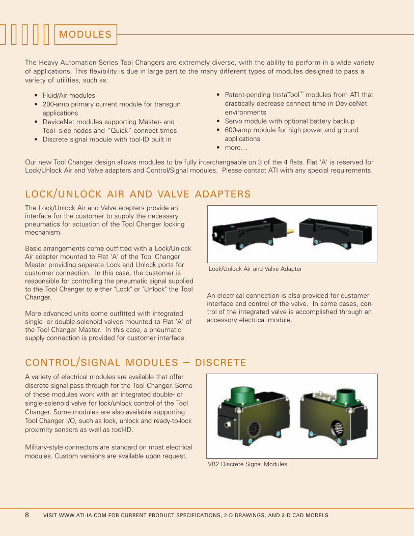
LOCK/UNLOCK AIR AND VALVE ADAPTERSThe Lock/Unlock Air and Valve adapters provide aninterface for the customer to supply the necessarypneumatics for actuation of the Tool Changer lockingmechanism.
Basic arrangements come outfitted with a Lock/UnlockAir adapter mounted to Flat 'A' of the Tool ChangerMaster providing separate Lock and Unlock ports forcustomer connection. In this case, the customer isresponsible for controlling the pneumatic signal suppliedto the Tool Changer to either "Lock" or "Unlock" the ToolChanger.
More advanced units come outfitted with integratedsingle- or double-solenoid valves mounted to Flat 'A' ofthe Tool Changer Master. In this case, a pneumaticsupply connection is provided for customer interface.
An electrical connection is also provided for customerinterface and control of the valve. In some cases, con-trol of the integrated valve is accomplished through anaccessory electrical module.
Lock/Unlock Air and Valve Adapter
The Heavy Automation Series Tool Changers are extremely diverse, with the ability to perform in a wide varietyof applications. This flexibility is due in large part to the many different types of modules designed to pass avariety of utilities, such as:
Our new Tool Changer design allows modules to be fully interchangeable on 3 of the 4 flats. Flat 'A' is reserved forLock/Unlock Air and Valve adapters and Control/Signal modules. Please contact ATI with any special requirements.
CONTROL/SIGNAL MODULES – DISCRETEA variety of electrical modules are available that offerdiscrete signal pass-through for the Tool Changer. Someof these modules work with an integrated double- orsingle-solenoid valve for lock/unlock control of the ToolChanger. Some modules are also available supportingTool Changer I/O, such as lock, unlock and ready-to-lockproximity sensors as well as tool-ID.
Military-style connectors are standard on most electricalmodules. Custom versions are available upon request.
VB2 Discrete Signal Modules
VISIT WWW.ATI-IA.COM FOR CURRENT PRODUCT SPECIFICATIONS, 2-D DRAWINGS, AND 3-D CAD MODELS 9
FLUID, AIR AND VACUUM MODULES
CONTROL/SIGNAL MODULES – DEVICENET
Electrical Feed-through
Two standard “mini” style power and signal connectorsare provided for ODVA-compliant DeviceNet interfacingon the Master and Tool modules. When the Tool Changeris coupled, the Master and Tool DeviceNet modulescommunicate with each other using a spring-loaded pinblock. A flexible boot surrounds the pin block to seal theconnection from moisture and liquid while coupled.
Pneumatic Valve
A double-solenoid-actuated pneumatic valve is integratedwith the DA2 DeviceNet Master module for control ofthe locking mechanism. A single solenoid with springreturn is used for the DB2 module. A double solenoid-actuated or single solenoid spring return valve can beintegrated with the DeviceNet Master module to controlthe Tool Changer locking mechanism.
Tool Stand Interlock
The DeviceNet modules are outfitted with a patentedTool Stand Interlock™ (TSI) connector that is wireddirectly into the unlock solenoid valve circuit. Using thisconnector, a switch can be integrated that will allow thesolenoid valve to uncouple the Tool Changer only whenthe Tool is in the Tool Stand. Teach plugs are available toclose the solenoid valve circuit during setup and mainte-nance scenarios.
Tool-ID
The DeviceNet Tool module uses a series of five 0–9switches for setting tool-ID. This allows the customer todistinguish between the different Tools that are beingoperated and controlled through the DeviceNet network.
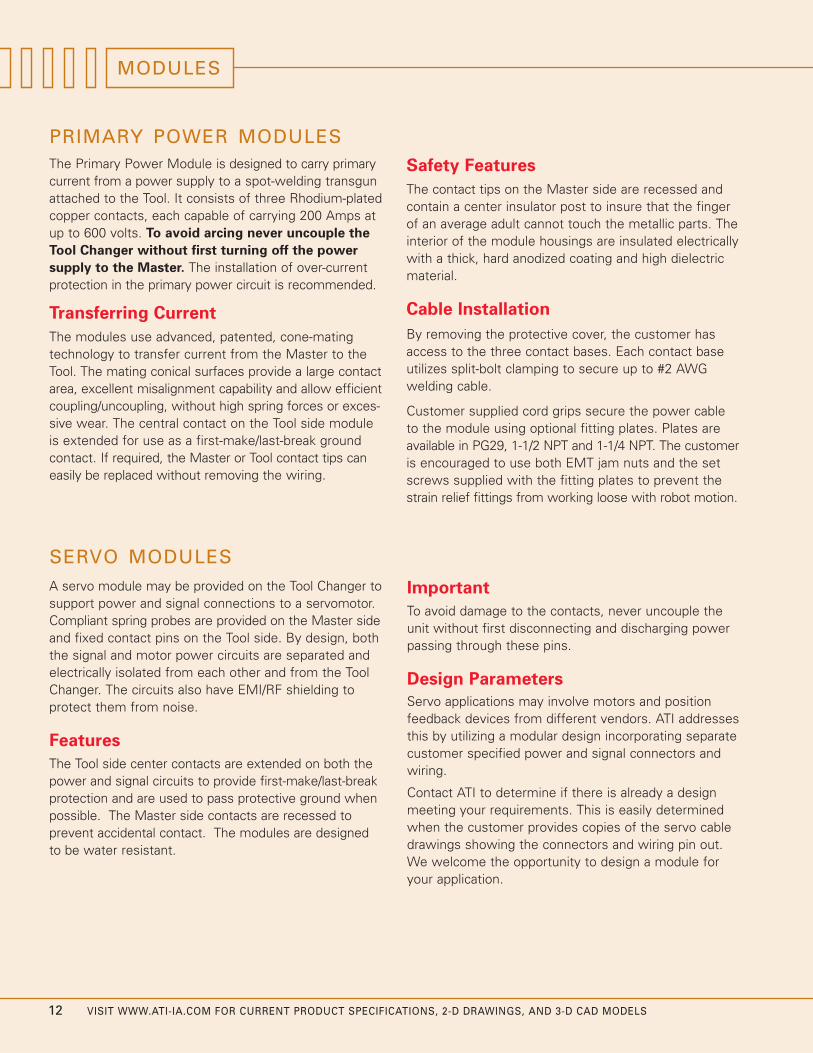
The Standard Series Module Mounting Adapter isdesigned to work with a variety of accessory modulesfrom the ATI Standard Series Tool Changers. A completelist of compatible modules is available online atwww.ati-ia.com.
STANDARD SERIES MODULE MOUNTING ADAPTER
JJ2 Module Mounting Adapter Assembly
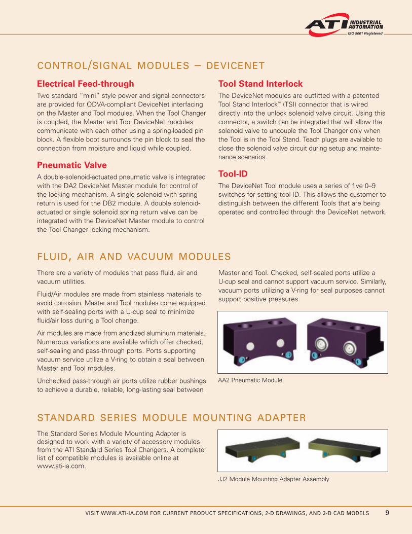
There are a variety of modules that pass fluid, air andvacuum utilities.
Fluid/Air modules are made from stainless materials toavoid corrosion. Master and Tool modules come equippedwith self-sealing ports with a U-cup seal to minimizefluid/air loss during a Tool change.
Air modules are made from anodized aluminum materials.Numerous variations are available which offer checked,self-sealing and pass-through ports. Ports supportingvacuum service utilize a V-ring to obtain a seal betweenMaster and Tool modules.
Unchecked pass-through air ports utilize rubber bushingsto achieve a durable, reliable, long-lasting seal between
Master and Tool. Checked, self-sealed ports utilize a U-cup seal and cannot support vacuum service. Similarly,vacuum ports utilizing a V-ring for seal purposes cannotsupport positive pressures.
AA2 Pneumatic Module

10 VISIT WWW.ATI-IA.COM FOR CURRENT PRODUCT SPECIFICATIONS, 2-D DRAWINGS, AND 3-D CAD MODELS
ATI INSTATOOL MODULES FOR DEVICENET
0 1 2 3 4 5 6 7 8 9
Old DeviceNet
New Quick Connect
ATI InstaTool™
Time (Seconds)
Maximum Time from Tool Connect
to tool-ID Read
DH3-M/DH2-T InstaTool modules for DeviceNet
New Innovation Greatly Reduces Timeand Complexity for Tool Changes inDeviceNet Environments.
DeviceNet is a popular industrial communications busused to connect industrial devices and reduce or elimi-nate time-consuming discrete wiring.
The Problem
With the obvious benefits of DeviceNet technologycomes the inevitable delay that occurs during tool identification—as long as 8 seconds at each Tool change.The cumulative effect of these delays is a loss of produc-tion time. This compounded effect becomes a factor inreducing manufacturing productivity.
In an effort to minimize this delay, a new DeviceNetstandard (Quick Connect) has been released which couldpotentially reduce this delay to 2 to 3 seconds. This isstill a noticeable delay during an application process.
ATI InstaTool solves the problem.
The Solution: ATI InstaTool Technology
With ATI InstaTool, long delays for tool identification andtooling I/O are a thing of the past. By using ATI InstaTooltechnology, the new Tool-side module communicatestool-ID and tooling I/O to the Master/robot module injust tenths of a second after Tool Changer coupling. Thereis no longer a need to establish a DeviceNet node on theTool side, which in turn prevents power-ups from havingto negotiate lengthy DeviceNet protocol sequences.Tooling is available on the network in under a second.
Best of all, there are no costly upgrades of DeviceNetscanner and master controller equipment required toenjoy the substantial benefits of ATI InstaTool.
Product Advantages
Near-Instant Connection and Tool Identification:
With InstaTool, tool-ID occurs within 150 milliseconds, ascompared to up to 8 seconds using current technology.tool I/O is available within 700 milliseconds.
Reduction in Time: No delay means overall cycle timeis reduced and production is increased. This advantageis heightened in applications with multiple Tool changes.
Reduced DeviceNet Node Management: With ATIInstaTool and InstaBus™ technology, the Tool ChangerMaster node handles 160 I/O points downstream,resulting in fewer DeviceNet nodes to manage.
Tool-ID Passes Through Master: Systems with multipleMasters and Tools can positively identify which Toolsare connected to each Master.
Tool Stand Interlock (TSI): A patented Tool StandInterlock feature is provided on the Tool/slave side forsafer Tool Changer operation. The TSI allows uncouplingonly when the Tool Changer is in the Tool Stand.Customers have the option to choose mechanical orproximity sensor switches to close the TSI circuitry.
Additional Safety Features: Additional DeviceNet inputsare provided to identify unsafe operating conditions.Customer operating software can be programmed tohalt Tool Changer operation when unsafe conditions exist.

VISIT WWW.ATI-IA.COM FOR CURRENT PRODUCT SPECIFICATIONS, 2-D DRAWINGS, AND 3-D CAD MODELS 11
ATI InstaBus
SubNode SubNode SubNode
DeviceNet Controller
Node Node Node
Node
Tool Changer Master Side
InstaTool
Tool Changer Tool Side
Tool ID
DeviceNet Controller
Node Node Node
Node
Tool Changer Master Side
Tool Changer Tool Side
Node Node
Tool ID
Node
Standard Network
Before ATI InstaTool, the DeviceNet signal passedfrom the DeviceNet controller, through the Masterside to the Tool side of the Tool Changer, then on todownstream nodes. With this method, each time anew Tool side connection is made, up to an 8-secondstart-up delay occurs before tool identification anddownstream I/O can be read and the application cancontinue.
ATI Solution
With InstaTool, the DeviceNet signal effectively stopsat the Tool Changer Master, creating an always-onconnection to that Master node. Using patent-pendinghigh-speed technology, the Master node handles allI/O communication downstream from the Master. Theresult is a connect time of less than 150 millisecondsfor tool-ID and under 700 milliseconds for tool I/O.tool I/O appears at the Master node.
Standard InstaToolutilizes off-the-shelf I/O blocks onthe downstream InstaBus. Two Bytes of data fromeach I/O block is supported. A “Super-Node” versionof InstaTool supports the use of a single, large I/Odevice on the InstaBus. The large I/O device can haveup to 160 I/O points.
DeviceNet—With and Without ATI InstaTool
The illustrations below indicate the fundamental differences between standard DeviceNet connectivity and the newATI InstaTool technology.
Up to160 I/O
SERVO MODULESA servo module may be provided on the Tool Changer tosupport power and signal connections to a servomotor.Compliant spring probes are provided on the Master sideand fixed contact pins on the Tool side. By design, boththe signal and motor power circuits are separated andelectrically isolated from each other and from the ToolChanger. The circuits also have EMI/RF shielding to protect them from noise.
Features
The Tool side center contacts are extended on both thepower and signal circuits to provide first-make/last-breakprotection and are used to pass protective ground whenpossible. The Master side contacts are recessed to prevent accidental contact. The modules are designedto be water resistant.
Important
To avoid damage to the contacts, never uncouple theunit without first disconnecting and discharging powerpassing through these pins.
Design Parameters
Servo applications may involve motors and positionfeedback devices from different vendors. ATI addressesthis by utilizing a modular design incorporating separatecustomer specified power and signal connectors andwiring.
Contact ATI to determine if there is already a designmeeting your requirements. This is easily determinedwhen the customer provides copies of the servo cabledrawings showing the connectors and wiring pin out.We welcome the opportunity to design a module foryour application.
MODULES
12 VISIT WWW.ATI-IA.COM FOR CURRENT PRODUCT SPECIFICATIONS, 2-D DRAWINGS, AND 3-D CAD MODELS
PRIMARY POWER MODULESThe Primary Power Module is designed to carry primarycurrent from a power supply to a spot-welding transgunattached to the Tool. It consists of three Rhodium-platedcopper contacts, each capable of carrying 200 Amps atup to 600 volts. To avoid arcing never uncouple the
Tool Changer without first turning off the power
supply to the Master. The installation of over-currentprotection in the primary power circuit is recommended.
Transferring Current
The modules use advanced, patented, cone-matingtechnology to transfer current from the Master to theTool. The mating conical surfaces provide a large contactarea, excellent misalignment capability and allow efficientcoupling/uncoupling, without high spring forces or exces-sive wear. The central contact on the Tool side moduleis extended for use as a first-make/last-break groundcontact. If required, the Master or Tool contact tips caneasily be replaced without removing the wiring.
Safety Features
The contact tips on the Master side are recessed andcontain a center insulator post to insure that the fingerof an average adult cannot touch the metallic parts. Theinterior of the module housings are insulated electricallywith a thick, hard anodized coating and high dielectricmaterial.
Cable Installation
By removing the protective cover, the customer hasaccess to the three contact bases. Each contact baseutilizes split-bolt clamping to secure up to #2 AWGwelding cable.
Customer supplied cord grips secure the power cableto the module using optional fitting plates. Plates areavailable in PG29, 1-1/2 NPT and 1-1/4 NPT. The customeris encouraged to use both EMT jam nuts and the setscrews supplied with the fitting plates to prevent thestrain relief fittings from working loose with robot motion.

VISIT WWW.ATI-IA.COM FOR CURRENT PRODUCT SPECIFICATIONS, 2-D DRAWINGS, AND 3-D CAD MODELS 13
MODULES AND OPTIONS
ATI Heavy Automation Tool Changers are designed with flexibility in mind. By simply choosing the proper utility modules (primary power, air, fluid, DeviceNet, and more), a Tool Changer can be configured for optimalperformance in your application.
Discrete Signal Modules
SA2-M Discrete Master, 26-pin Amphenol, 19-pin Block, Supports L/U/R1/R2 Sensors, Not Intended for Use with an Integrated Valve
SA2-T Discrete Tool, 19-pin Amphenol, 19-pin Block, (19) Pass-Thru's
SA3-T Discrete Tool, 19-pin Amphenol, 19-pin Block, (15) Pass-Thru's, 0-9 tool-ID
SA4-T Discrete Tool, 19-pin Amphenol, 19-pin Block, (11) Pass-Thru's, 0-99 tool-ID
VA2-M Discrete Master, 26-pin Amphenol, 19-pin Block, Supports L/U/R1/R2 Sensors and Integrated Valve, works with SA Tool-side modules, TSI on Master
VB2-M Discrete Master, 26-pin Amphenol, 19-pin Block, Supports L/U/R1/R2 Sensors and Integrated Valve,TSI on Tool, works with VB Tool-side modules
VB2-T Discrete Tool, 19-pin Amphenol, 19-pin Block, Tool Stand Interlock, (16) Pass-Thru's
VB3-T Discrete Tool, 19-pin Amphenol, 19-pin Block, Tool Stand Interlock, (12) Pass-Thru's, 0-9 tool-ID
VB4-T Discrete Tool, 19-pin Amphenol, 19-pin Block, Tool Stand Interlock, (8) Pass-Thru's, 0-99 tool-ID
Part # Description
Lock/Unlock Air and Valve Adapters
JA -M Lock/Unlock Air Adapter Master, NPT Ports, 2 - QC-210 or 3 - QC-310 and QC-510
JB -M Lock/Unlock Air Adapter Master, G Ports, 2 - QC-210 or 3 - QC-310 and QC-510
JC -M Valve Adapter Master, Single Solenoid, NPT Ports, 2 - QC-210 or 3 - QC-310 and QC-510
JD -M Valve Adapter Master, Single Solenoid, G Ports, 2 - QC-210 or 3 - QC-310 and QC-510
JE -M Valve Adapter Master, Double Solenoid, NPT Ports, 2 - QC-210 or 3 - QC-310 and QC-510
JF -M Valve Adapte Master, Double Solenoid, G Ports, 2 - QC-210 or 3 - QC-310 and QC-510
JG -M A/C Valve Adapter Master, Single Solenoid, NPT Ports, 2 - QC-210 or 3 - QC-310 and QC-510
Part # Description
DeviceNet/InstaTool Modules
DA2-M Quick Connect Capable Master Module, Double Solenoid, TSI on the Master
DA2-T Quick Connect Capable Tool Module, tool-ID to identify robot, line and tool number
DB2-M Quick Connect Capable Master Module, Single Solenoid, TSI on the Tool
DB2-T Quick Connect Capable Tool Module, TSI on the Tool (Mechanical Switch), 5 independent switch
DB8-M Quick Connect Capable Master Module, Safety PLC
DH3-M InstaTool Master, Supports Integrated Valve with Tool Stand Interlock on Tool Side
DH2-T InstaTool Tool, Mechanical Switch Tool Stand Interlock, 5-Independent Switch tool-ID (mates w/DH3-M)
DH7-M InstaTool Master, Harting Connector, Supports Safety PLC Valve Control
DH4-T InstaTool Tool, 5 independent switch tool-ID (mates w/ DH7-M)
DH9-M InstaTool Master, Harting connector, Air Blow-Off Valve Control, Quick-Boot Valve Support and NO Safety PLC. (Only works with Single-Solenoid Valve Adapters)
DH5-T InstaTool Tool, Quick Boot Valve, Mechanical Switch TSI, 5-Independent Switch tool-ID, SEM (Only works with Single-Solenoid Valve Adapters)
Part # Description
MODULES AND OPTIONS
14 VISIT WWW.ATI-IA.COM FOR CURRENT PRODUCT SPECIFICATIONS, 2-D DRAWINGS, AND 3-D CAD MODELS
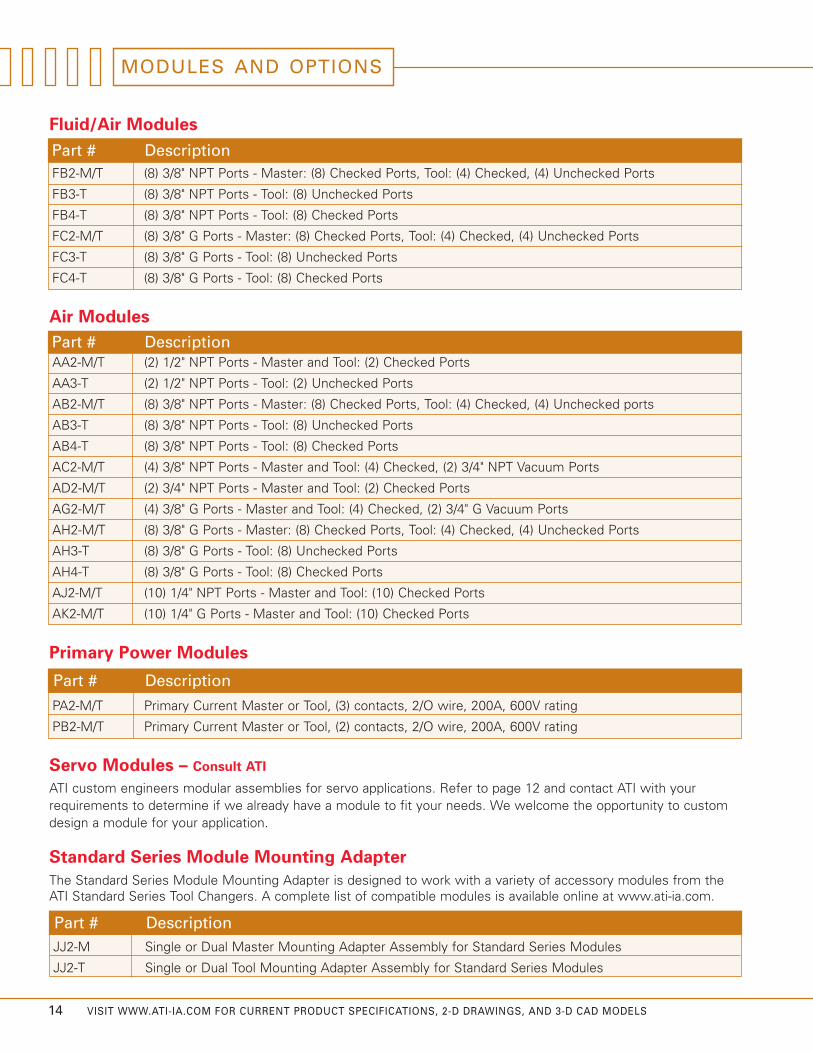
Servo Modules – Consult ATI
Fluid/Air Modules
FB2-M/T (8) 3/8" NPT Ports - Master: (8) Checked Ports, Tool: (4) Checked, (4) Unchecked Ports
FB3-T (8) 3/8" NPT Ports - Tool: (8) Unchecked Ports
FB4-T (8) 3/8" NPT Ports - Tool: (8) Checked Ports
FC2-M/T (8) 3/8" G Ports - Master: (8) Checked Ports, Tool: (4) Checked, (4) Unchecked Ports
FC3-T (8) 3/8" G Ports - Tool: (8) Unchecked Ports
FC4-T (8) 3/8" G Ports - Tool: (8) Checked Ports
Part # Description
ATI custom engineers modular assemblies for servo applications. Refer to page 12 and contact ATI with yourrequirements to determine if we already have a module to fit your needs. We welcome the opportunity to customdesign a module for your application.
Primary Power Modules
PA2-M/T Primary Current Master or Tool, (3) contacts, 2/O wire, 200A, 600V rating
PB2-M/T Primary Current Master or Tool, (2) contacts, 2/O wire, 200A, 600V rating
Part # Description
AA2-M/T (2) 1/2" NPT Ports - Master and Tool: (2) Checked Ports
AA3-T (2) 1/2" NPT Ports - Tool: (2) Unchecked Ports
AB2-M/T (8) 3/8" NPT Ports - Master: (8) Checked Ports, Tool: (4) Checked, (4) Unchecked ports
AB3-T (8) 3/8" NPT Ports - Tool: (8) Unchecked Ports
AB4-T (8) 3/8" NPT Ports - Tool: (8) Checked Ports
AC2-M/T (4) 3/8" NPT Ports - Master and Tool: (4) Checked, (2) 3/4" NPT Vacuum Ports
AD2-M/T (2) 3/4" NPT Ports - Master and Tool: (2) Checked Ports
AG2-M/T (4) 3/8" G Ports - Master and Tool: (4) Checked, (2) 3/4" G Vacuum Ports
AH2-M/T (8) 3/8" G Ports - Master: (8) Checked Ports, Tool: (4) Checked, (4) Unchecked Ports
AH3-T (8) 3/8" G Ports - Tool: (8) Unchecked Ports
AH4-T (8) 3/8" G Ports - Tool: (8) Checked Ports
AJ2-M/T (10) 1/4" NPT Ports - Master and Tool: (10) Checked Ports
AK2-M/T (10) 1/4" G Ports - Master and Tool: (10) Checked Ports
Air Modules
Part # Description
Standard Series Module Mounting Adapter
JJ2-M Single or Dual Master Mounting Adapter Assembly for Standard Series Modules
JJ2-T Single or Dual Tool Mounting Adapter Assembly for Standard Series Modules
Part # Description
The Standard Series Module Mounting Adapter is designed to work with a variety of accessory modules from theATI Standard Series Tool Changers. A complete list of compatible modules is available online at www.ati-ia.com.
VISIT WWW.ATI-IA.COM FOR CURRENT PRODUCT SPECIFICATIONS, 2-D DRAWINGS, AND 3-D CAD MODELS 15
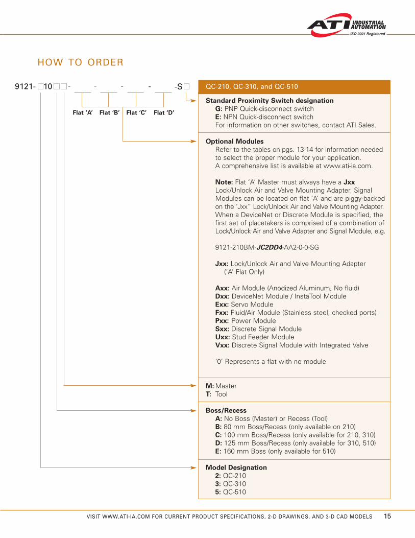
HOW TO ORDER
9121- 10 QC-210, QC-310, and QC-510
Standard Proximity Switch designation
G: PNP Quick-disconnect switch E: NPN Quick-disconnect switchFor information on other switches, contact ATI Sales.
Optional Modules
Refer to the tables on pgs. 13-14 for information neededto select the proper module for your application.A comprehensive list is available at www.ati-ia.com.
Note: Flat ‘A’ Master must always have a Jxx
Lock/Unlock Air and Valve Mounting Adapter. Signal Modules can be located on flat ‘A’ and are piggy-backed on the ‘Jxx” Lock/Unlock Air and Valve Mounting Adapter.When a DeviceNet or Discrete Module is specified, the first set of placetakers is comprised of a combination of Lock/Unlock Air and Valve Adapter and Signal Module, e.g.
9121-210BM-JC2DD4-AA2-0-0-SG
Jxx: Lock/Unlock Air and Valve Mounting Adapter (‘A’ Flat Only)
Axx: Air Module (Anodized Aluminum, No fluid)Dxx: DeviceNet Module / InstaTool ModuleExx: Servo ModuleFxx: Fluid/Air Module (Stainless steel, checked ports)Pxx: Power ModuleSxx: Discrete Signal ModuleUxx: Stud Feeder Module Vxx: Discrete Signal Module with Integrated Valve
‘0’ Represents a flat with no module
M: Master T: Tool
Boss/Recess
A: No Boss (Master) or Recess (Tool)B: 80 mm Boss/Recess (only available on 210)C: 100 mm Boss/Recess (only available for 210, 310)D: 125 mm Boss/Recess (only available for 310, 510)E: 160 mm Boss (only available for 510)
Model Designation
2: QC-2103: QC-3105: QC-510
-- -S--
Flat ‘A’ Flat ‘B’ Flat ‘C’ Flat ‘D’
16 VISIT WWW.ATI-IA.COM FOR CURRENT PRODUCT SPECIFICATIONS, 2-D DRAWINGS, AND 3-D CAD MODELS
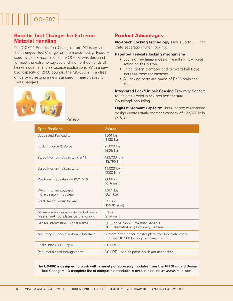
Product Advantages
No-Touch Locking technology allows up to 0.1 inchplate separation when locking.
Patented Fail-safe locking mechanisms
• Locking mechanism design results in low forceacting on the piston.
• Large piston diameter and outward ball travelincrease moment capacity.
• All locking parts are made of Rc58 stainlesssteel.
Integrated Lock/Unlock Sensing Proximity Sensorsto indicate Lock/Unlock position for safeCoupling/Uncoupling.
Highest Moment Capacity: Three locking mechanismdesign creates static moment capacity of 122,000 lb-in.(X & Y)
QC-602
Robotic Tool Changer for ExtremeMaterial Handling
The QC-602 Robotic Tool Changer from ATI is by far the strongest Tool Changer on the market today. Typicallyused by gantry applications, the QC-602 was designedto meet the extreme payload and moment demands ofheavy industrial and aerospace applications. With a pay-load capacity of 2500 pounds, the QC-602 is in a classof it’s own, setting a new standard in heavy capacityTool Changers.
Specifications Values
Suggested Payload Limit 2500 lbs(1130 kg)
Locking Force @ 80 psi 21,000 lbs(9525 kg)
Static Moment Capacity (X & Y) 122,000 lb-in(13,750 Nm)
Static Moment Capacity (Z) 49,000 lb-in(5500 Nm)
Positional Repeatability (X,Y, & Z) .0006 in(.015 mm)
Weight (when coupled) 128.1 lbs(no accessory modules) (58.1 kg)
Stack height when locked 5.51 in(139.91 mm)
Maximum allowable distance between 0.1 inMaster and Tool plates before locking (2.54 mm)
Sensor Information, Signal Name L/U (Lock/Unlock) Proximity SensorsRTL (Ready-to-Lock) Proximity Sensors
Mounting Surface/Customer Interface Custom patterns for Master plate and Tool plate based on three QC-200 locking mechanisms
Lock/Unlock Air Supply 3/8 NPT
Pneumatic pass-through ports 3/8 NPT – two air ports which are unchecked
The QC-602 is designed to work with a variety of accessory modules from the ATI Standard Series
Tool Changers. A complete list of compatible modules is available online at www.ati-ia.com.
QC-602
VISIT WWW.ATI-IA.COM FOR CURRENT PRODUCT SPECIFICATIONS, 2-D DRAWINGS, AND 3-D CAD MODELS 17
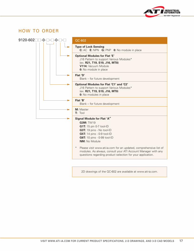
HOW TO ORDER
9120-602 QC-602
Type of Lock Sensing
C: AC E: NPN G: PNP 0: No module in place
Optional Modules for Flat ‘E’
J16 Pattern to support Various Modules*(ex. R21, T19, S19, J16, MT8)
V114: Vacuum Module 0: No module in place
Flat ‘D’
Blank – for future development
Optional Modules for Flat ‘C1’ and ‘C2’
J16 Pattern to support Various Modules*(ex. R21, T19, S19, J16, MT8) 0: No modules in place
Flat ‘B’
Blank – for future development
M: Master T: Tool
Signal Module for Flat ‘A’*
G3M: TW19G1T: 15 pin 0-7 tool-IDG3T: 19 pins - No tool-IDG5T: 14 pins - 0-9 tool-IDG6T: 10 pins - 0-99 tool-IDNM: No Module
* Please visit www.ati-ia.com for an updated, comprehensive list of modules. As always, consult your ATI Account Manager with any questions regarding product selection for your application.
-0- - -0- -
2D drawings of the QC-602 are available at www.ati-ia.com.
18 VISIT WWW.ATI-IA.COM FOR CURRENT PRODUCT SPECIFICATIONS, 2-D DRAWINGS, AND 3-D CAD MODELS
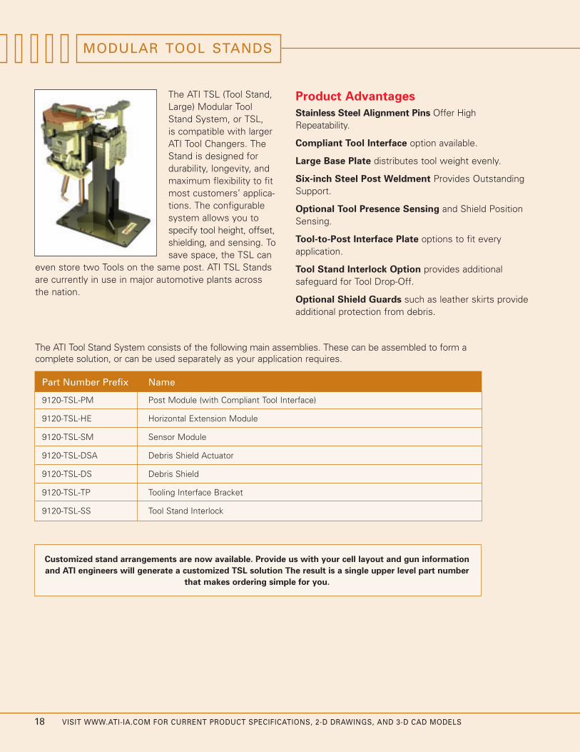
MODULAR TOOL STANDS
Product Advantages
Stainless Steel Alignment Pins Offer HighRepeatability.
Compliant Tool Interface option available.
Large Base Plate distributes tool weight evenly.
Six-inch Steel Post Weldment Provides OutstandingSupport.
Optional Tool Presence Sensing and Shield PositionSensing.
Tool-to-Post Interface Plate options to fit every application.
Tool Stand Interlock Option provides additional safeguard for Tool Drop-Off.
Optional Shield Guards such as leather skirts provideadditional protection from debris.
The ATI Tool Stand System consists of the following main assemblies. These can be assembled to form acomplete solution, or can be used separately as your application requires.
Part Number Prefix Name
9120-TSL-PM Post Module (with Compliant Tool Interface)
9120-TSL-HE Horizontal Extension Module
9120-TSL-SM Sensor Module
9120-TSL-DSA Debris Shield Actuator
9120-TSL-DS Debris Shield
9120-TSL-TP Tooling Interface Bracket
9120-TSL-SS Tool Stand Interlock
The ATI TSL (Tool Stand,Large) Modular ToolStand System, or TSL, is compatible with largerATI Tool Changers. TheStand is designed fordurability, longevity, andmaximum flexibility to fitmost customers’ applica-tions. The configurablesystem allows you tospecify tool height, offset,shielding, and sensing. Tosave space, the TSL can
even store two Tools on the same post. ATI TSL Standsare currently in use in major automotive plants acrossthe nation.
Customized stand arrangements are now available. Provide us with your cell layout and gun information
and ATI engineers will generate a customized TSL solution The result is a single upper level part number
that makes ordering simple for you.

VISIT WWW.ATI-IA.COM FOR CURRENT PRODUCT SPECIFICATIONS, 2-D DRAWINGS, AND 3-D CAD MODELS 19
Post Module
The ATI TSL Post Module includes awelded steel vertical post, a base plate,and an optional vertically-compliant inter-face for your tooling. Height, tool orien-tation, and compliance stiffness can allbe specified by the customer. ATI alsooffers a configuration of the TSL PostModule that allows for up to two Toolsto be mounted on the same post.
Horizontal Extension Module
The TSL Horizontal Extension Module isan option that provides more tool clear-ance than the standard TSL Post Module.ATI offers straight or right-angle exten-sions. Specific lengths are availableupon request.
Sensor Module
The TSL Sensor Module is an optionthat provides Tool Presence detection.The standard model mounts directly tothe TSL Post Module and incorporatesa proximity switch that senses a faceon the TSL Tooling Interface Bracket.The Sensor Module’s design featuresguard against collision.
Debris Shield Actuator
The TSL Debris Shield Actuator (DSA)positions the Debris Shield in the open orclosed position. On single Tool Stands, theDSA module can be oriented so that theshield swings in the vertical or horizontalplane. The shield will swing 90°-135°degrees rotationally for most arrange-ments. The powerclamp comes equippedwith integrated position sensing.
Debris Shield
The TSL Debris Shield mounts to a tubu-lar arm that in turn is mounted to theShield Actuator Unit. The Debris Shield isdesigned to cover the Tool Changer ToolSide unit when the Tool is in storage.The Debris Shield provides ample protec-tion from dust, weld spatter and otherdebris through the use of leather sideguards.
Tooling Interface Bracket
The TSL Tooling Interface Bracketmounts directly to your tooling, and isequipped with heavy-duty alignment pinand bushings that directly couple withthe Post Module compliant interface.Custom brackets are available uponrequest.
gniwS dleihS detargretnI htiW
WEIV DEDOLPXE
gnisneS noitisoP
005C-A632-MP-LST-0219
thgieH llarevO yficepS nac remotsuC
ecafretnI gnilooT tnailpmoC htiw eludoM tsoP lauD
1991-02-0329 eeSknalB
tekcarB ecafretnI gnilooT
eludoM rosneSecneserP looT
mrA dliehS7253-02-0073
1733-AMS-LST-0219
5114-PT-LST-0219
5253-531-ASD-LST-0219rotautcA dleihS sirbeD
531
8253B-71-SD-LST-0219ediW "71 ,dleihS sirbeDsdrauG ediS rehtaeL htiW
dleihS gniwS
531
PAT 21M )8(urhT
91
733
263
urhT
532
91
267
805
02)8(
012
WEIV POT
WEIV EDIS
15 201
91
701
73
521
481
ssenkcihT etalP
thgieH llarevO()remotsuC yB DBT
WEIV CIRTEMOSI
WEIV TNORF
ecnailpmoC
31mumixaMlacitreV
602
www.ati-ia.comATI INDUSTRIAL AUTOMATION 9230-20-1824TSL

Other ATI Products
Robotic Collision Sensor
Designed to prevent damage to robotic end-effectorsresulting from robot crashes. Features include:Automatic reset, high-repeatability, and large momentrotation.
Robotic and CNC Deburring Tools
These air-driven robotic tools cover a wide variety ofautomated deburring applications with fast cycle timesand clean, accurate cuts. The Radially-CompliantDeburring Tool is designed for removal of parting linesand flash, while the Axially-Compliant Deburring Tool isspecially designed for edge deburring and chamfering.
Robotic Rotary Joint
A device that allows unlimited rotation of end-of-armtooling without tangling or twisting robot tooling utilitylines. Utilizes advanced slip-ring technology to passelectrical and pneumatic signals from robot to tooling.
Multi-Axis Force/Torque Sensor
Measures the full six components of force andtorque. High overload protection and high signal-to-noise ratio. Used in robotic and research applications.
Automated Assembly Alignment Device
An insertion device using Remote Center Compliancetechnology that helps assembly machines automaticallyalign close-fitting parts, preventing jamming and galling.
Company Profile
ATI Industrial Automation is a world-leading developer of Automatic Tool Changers, Multi-AxisForce/Torque Sensing Systems, Compliance Devices,Robotic Collision Sensors, Robotic Deburring Tools,and Robotic Rotary Joints. Our products are foundin thousands of successful applications around theworld.
Since 1982, our engineers have been developingcost-effective, state-of-the-art products and solutionsto improve manufacturing productivity.
Our Mission is to provide customers around theworld with high-quality robotic peripheral devices,tooling and sensors that enhance customer prof-itability by increasing the effectiveness, flexibility,safety and productivity of their automation applications.We accomplish this through continuous improvementof existing products, product customization andnew product innovation.
Our engineering-centric staff focuses on providingcustomer solutions to robotic, automation andsensing applications.
Our Quality Policy
ATI Industrial Automation strives to provide customer satisfaction through continual improvementof on-time delivery, quality and reliability, and a constant focus on innovation and profitability.
© Copyright by ATI Industrial Automation, Inc. 2005. All rights reserved. 9205-20-1013 November, 2005
Pinnacle Park1031 Goodworth DriveApex, NC 27539 USA
+1 919.772.0115 +1 919.772.8259 faxE-mail: [email protected]
Related Documents