ME 250 DESIGN AND MANUFACTURING I Fall 2015 Robot Machine Player (RMP) 250 Team 13 ME 250 Section #10, Zone 2 Team Members Nadim Bari Matthew Dee Matthew George Diego Montano Thomas Saylor

Welcome message from author
This document is posted to help you gain knowledge. Please leave a comment to let me know what you think about it! Share it to your friends and learn new things together.
Transcript

ME 250 DESIGN AND MANUFACTURING I
Fall 2015
Robot Machine Player (RMP) 250 Team 13
ME 250 Section #10, Zone 2 Team Members
Nadim Bari Matthew Dee
Matthew George Diego Montano Thomas Saylor
1
Table of Contents Table of Contents 1. ABSTRACT…………………………………………………………………………………2 2. INTRODUCTION…………………………………………………………………………..2 3. PROTOTYPE DESIGN……………………………………………………………………3 3.1. Strategy and Zone Strategy………………………………………………………………3 3.2. Functional Requirements, Specifications, and Target Values ……………………….4 3.3. Design Concepts and Subsystems………………………………………………………5 3.4. Analysis …………………………………………………………………………………….7 3.5. Final Design and CAD Model ……………………………………………………………12 4. PROTOTYPE MANUFACTURING ……………………………………………………..15 4.1. Manufacturing Process …………………………………………………………………..15 4.2. Bill of Materials ……………………………………………………………………………16 5. PROTOTYPE TESTING …………………………………………………………………20 5.1. Preliminary Test……………………………………………………………………………20 5.2. Scrimmage Results and Redesign Based on Scrimmage ……………………………21 5.3. Discussion of Competition Results ……………………………………………………...22 6. DISCUSSION AND RECOMMENDATIONS …………………………………………..23 6.1. Project Summary ………………………………………………………………………….23 6.2. Recommendation for Mass Production …………………………………………………23 6.3. Future Project Idea ……………………………………………………………………….24 7. REFERENCES…………………………………………………………………………….24 8. ACKNOWLEDGEMENTS………………………………………………………………...24 APPENDICES ………………………………………………………………………………………25 A. Preliminary design concept SKETCHES………………………………………………...25 A.1. Preliminary Design Concept Sketch 1……………………………………………………25 A.2. Preliminary Design Concept Sketch 2……………………………………………………25 A.3. Preliminary Design Concept Sketch 3……………………………………………………26 B. Dimensioned Drawings and manufacturing plans………………………………………26 B.1. Dimensioned Drawings of Individual Parts………………………………………………26 B.2. Manufacturing plans………………………………………………………………………..36 C. PURCHASED AND TRADED ITEMS……………………………………………………54 C.1 Purchased parts…………………………………………………………………………….54 C.2. Traded parts (inter-squad) ………………………………………………………………..54
2
1. ABSTRACT The following report will discuss the initial development, iterative designs, and production of our Robotic Machine Player (RMP). We will discuss what our squad’s strategy was and what zone we were assigned to navigate. We will then proceed to explain our functionality requirements and discuss the calculations involved in producing a successful robot. From this we will discuss our final design consisting of large wheels in a driving subassembly and a winch and pulley in a lifting subassembly. Then we will discuss the manufacturing of the robot’s components and any difficulties arising during the production. Next we will discuss what preliminary testing was done to assure our robot’s functionality and the results from our scrimmage and match. Finally, we will discuss the impact of the project and what plans we have for future development.
2. INTRODUCTION Background The Michigan Ninja Relay is a competition held among all squads during the CoE Design Expo to determine the overall champion. The competition is designed for students in teams of four or five, to design and build a remote-controlled machine, called an RMP-250 (Robotic Machine Player). The teams are a part of a squad formed by the 4 teams belonging to a lab section. Each team is assigned to one of the 4 zones of different obstacle challenges, where several Cubes (blocks with the M logo) are placed. The RMPs in each squad will collaborate together to pass the Cubes from one zone to another, and ultimately, into the GOAL basket. Problem statement The squad’s objective is to score as many points as possible within the 3-minute time limit. Scoring can be done by moving Cubes from one zone to the preceding zone. Cubes in each zone are either the ones initially placed in the zone, or the ones transported from the previous zone by another RMP. Different scores are given depending on the initial and final locations of Cubes. We were challenged to design and build a robotic machine player (RMP) that is best suited to navigate and score points from zone 2. The challenge posed in zone two is a “sea of ping-pong balls”. All RMPs were given the following general design requirements: Each RMP must initially fit in a volume no larger than 10" x 10” x 12", each RMP must use the provided power/control box and the wireless controller, the provided control box must be attached to your RMP using velcro, each RMP must contain no more than four (4) remotely and independently controlled axes of motion, and each RMP must not possess any devices and may not execute actions that pose a risk of injury to yourself or others.

3
3. PROTOTYPE DESIGN
3.1. Strategy and Zone Strategy Our squad strategy is to get as many cubes as possible into the goal within the 3 minute time frame. Zone 1 and zone 2 cubes have the highest priorities to be placed into the goal. Cubes are intended to be placed as close to the center pillar of the playing field as possible and this will allow easy passing from zone-to-zone. RMP1 picks up all of its cubes then it will station itself in the corner closest to the center pillar. Meanwhile, zone 2 RMP will pick up its cubes and pass them over the wall to RMP3. During this time RMP3 will pick up its own cubes and return to its original position. RMP3 will then take its cubes and places them over the wall of the maze, closest to the border between zone 3 and 4 (drop off area) and will repeat this process once it retrieves zone 2 cubes. RMP2 will receive cubes from RMP1 and pass those cubes to RMP3. Meanwhile, RMP4 will clear a path and pick up cubes from the drop off area in zone 3 and attempt to place them in the goal. After RMP3 receives the zone 1 cubes from RMP2, it will navigate through the maze and pass the cubes over the wall into zone 4. After RMP3 places zone 1 cubes into zone 4, it will help transfer any remaining cubes from the drop off area into zone 4. Meanwhile, RMP4 will prioritize in placing zone 1, zone 2, and zone 3 cubes into the goal and with time remaining, it will then place zone 4 cubes into the goal. Our team was assigned zone 2. We had briefly considered a strategy in which all robots would meet in the middle of their zones. This would provide extra space and extra room for error as the robots would have more room to be positioned. However, our strategy was chosen over this strategy because of the time that would be saved by meeting in the middle and the relatively large room for error provided. We were assigned zone 2 by our squad. Our zone goal is to make sure all zone 1 and 2 cubes are placed into zone 3. The best way to achieve this is for RMP2 to be able to collect all M2 cubes at once and drive off that ledge to wade through the sea of ping pong balls. RMP2 will then transfer them over the wall into zone 3. RMP2 should then navigate its way through the sea of ping pong balls to the zone 1 border nearest to center pillar and wait to receive zone 1 cubes from RMP1. RMP2 will then finally transfer these cubes over the wall into zone 3 nearest the center pillar. Figure 1 shows a visual representation of our RMP’s zone strategy path for the Design Expo competition.

4
Figure 1. Zone Strategy
3.2. Functional Requirements, Specifications, and Target Values Functional Requirement 1 Our first functional requirement for RMP2 is that it should be able to hold 6 cubes at once. This is important because we wanted to design an RMP that can hold all cubes delivered to us by zone 1. A quantifiable specification for this requirement is that we can measure the weight that the RMP2 can hold in the bucket. We measured the weight of 6 cubes. The target value for this functional requirement was .9lbs. Functional Requirement 2 Our second functional requirement for RMP2 is that it should be able to drop from the ledge and navigate its way through the sea of ping pong balls without tipping over. A quantifiable specification for this requirement can be found by analyzing the torques on the RMP in a maximum gradient scenario where the back wheel is on the ledge and the front wheel is on the table surface. We measured the height of the ledge. The target value for this functional requirement was for the RMP to be able to withstand a 2 inch gradient change without tipping. Functional Requirement 3 Our final functional requirement for RMP2 is that it should be able to transfer at least six cubes above the height of the borderline wall. A quantifiable specification for this requirement is that we can measure the height that the RMP can lift. We measured the height of the wall. The target value for this functional requirement was for the RMP to lift 6 cubes to a height of 11 inches.

5
3.3. Design Concepts and Subsystems Design Concept 1: Forklift The forklift has 4 thin wheels with a large enough diameter to keep the body above the ping pong balls. A pulley system will be attached to a winch and the bucket for raising and lowering the forklift. A peg will tilt the forklift as it is raised to deposit the cubes into the next zone. Design Concept 2: Digger The digger has 4 thin wheels, large enough to keep the body above the ping pong balls. A rod will be attached to a pivot to raise and lower the bucket. The rod will be telescoping to provide extra length. The bucket to hold cubes will be on a pivot with gravity balancing it. Design Concept 3: Seesaw The seesaw has 4 thin wheels with a large enough diameter to keep the body above the ping pong balls. A pivot point in the middle of the RMP will be attached to the bucket on the front and a counterweight on the back. A track and peg system will raise and lower the counterweight and the bucket. The bucket will hold cubes and have pegs at the top to tip the bucket.
Table 1: Design Concept Selection Features Weighting
Requirement Weight Design Concept 1: Fork Lift (Baseline)
Design Concept 2: Digger
Design Concept 3: SeeSaw
Able to pick up five cubes from area M2 4 0 -2 +1
Able to withstand and hold six cubes being transferred to it from zone 1
3 0 -1 +1
Able to drop down from ledge to navigate its ways through the sea of ping pong balls
5 0 0 0
Able to lift and transfer at least six cubes over wall
3 0 +1 +2
Manufacturability 4 0 +1 -3
Creativity 1 0 -2 +2
Total 0 -8-3+0+3+4-2= -6
4+3+0+6-12+2= 3

6
Our team selected design concept 1: Fork Lift as our final design concept. RMP2 will move using 4 thin wheels with diameters large enough to keep its body above the ping pong balls. A pulley system will be attached to a winch and a bucket (located in the front of RMP2) for raising and lowering the forklift. The forklift will be able to scoop up 5 cubes and lift 6 cubes. RMP2 will first collect all of its cubes and transfer them over to zone 3. It will then interact with RMP1 by having RMP1 place all of its cubes into the bucket. It will then take zone 1 cubes and transfer them to zone 3. Although the Seesaw design concept scored highest in the pugh chart (Table 1, pg 4), we chose the forklift design concept in favor of this design concept because the seesaw design would be extremely difficult to manufacture. In order to raise and lower the seesaw arm smoothly, the tolerances between the guide rail slots would have to be extremely accurate otherwise because if the arm gets even slightly misaligned it would become stuck. Furthermore the seesaw would require speciality parts such as small bearings and a rack and pinion system. Another complication of this design is the counterweight system. Another complication is that the torque from the counterweights would have to be very precisely calibrated else the arm would swing one way or the other. The RMP was planned to move with large radius wheels to avoid the ping pong balls and easily glide off of the ledge. The bucket up front will collect and delivers cubes, containing while the robot is moving across the playing field. The winch and pulley system will be used to raise and lower the bucket, which will be kept rigidly outward by the attached guides. Arms at the top of the RMP will allows for the bucket to tip.
Figure 2: Final Design Concept of our RMP

7
Subsystem 1: Power Transmission to Wheels Power will be transported to the wheels by way of a dual gearbox. This will allow us to drive two wheels with one motor, and they will be able to turn independently of each other. Subsystem 2: Cube Raising Mechanism The cubes will be loaded into the bucket and then the bucket will be raised as the winch winds the kevlar string in. The bucket will be attached to a jig which will slide in a hollow guide rail.
3.4. Analysis
Preliminary Statics Analysis Entire System on Level Surface
Known: Fc= 0.9lbs FB= 0.224lbs FW=0.303lbs FM=0.25lbs FM2=0.738lbs FBD= 1.999lbs 1= 0.052in 2=0.698in 3=0.5in 4=0.88in 5=0.295in 6=2.285in 9=0.125in

8
10=2.25in 11=0.053in 12=1.308in Calculations:
𝑀 (𝑜)(𝑐𝑙𝑜𝑐𝑘𝑤𝑖𝑠𝑒)= -‐Fc(1.25)-‐FB(1.198)+FM(.88)+FBD(1.175)+FW(4)=3.627 lbs. in. Because the RMP has a positive moment about the front wheel, it will not tip on level ground.

9

10

11
12
3.5. Final Design and CAD Model
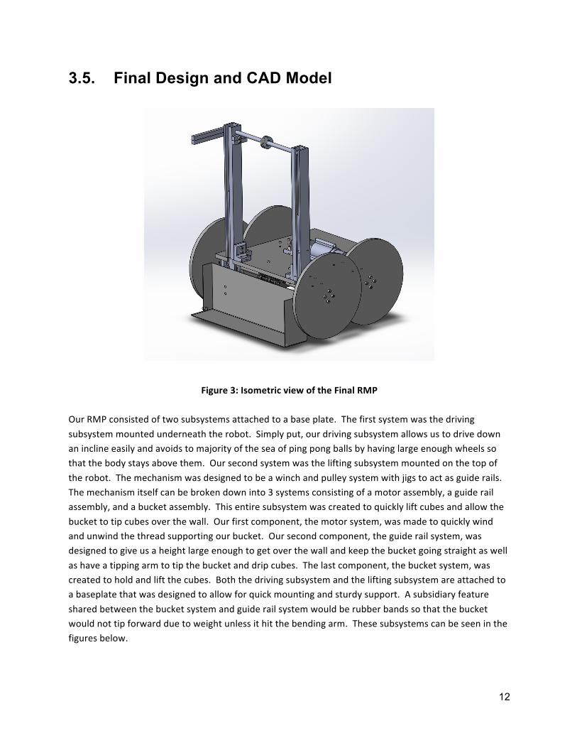
Figure 3: Isometric view of the Final RMP Our RMP consisted of two subsystems attached to a base plate. The first system was the driving subsystem mounted underneath the robot. Simply put, our driving subsystem allows us to drive down an incline easily and avoids to majority of the sea of ping pong balls by having large enough wheels so that the body stays above them. Our second system was the lifting subsystem mounted on the top of the robot. The mechanism was designed to be a winch and pulley system with jigs to act as guide rails. The mechanism itself can be broken down into 3 systems consisting of a motor assembly, a guide rail assembly, and a bucket assembly. This entire subsystem was created to quickly lift cubes and allow the bucket to tip cubes over the wall. Our first component, the motor system, was made to quickly wind and unwind the thread supporting our bucket. Our second component, the guide rail system, was designed to give us a height large enough to get over the wall and keep the bucket going straight as well as have a tipping arm to tip the bucket and drip cubes. The last component, the bucket system, was created to hold and lift the cubes. Both the driving subsystem and the lifting subsystem are attached to a baseplate that was designed to allow for quick mounting and sturdy support. A subsidiary feature shared between the bucket system and guide rail system would be rubber bands so that the bucket would not tip forward due to weight unless it hit the bending arm. These subsystems can be seen in the figures below.

13
Figure 4: Side View of the Final RMP
Figure 5: Top View of the Final RMP

14
Figure 6: Bottom View of the Final RMP
Table 2: Table of Parts and Design Explanations
Part # Part Name Design Explanation
4 Wheels 5.375” Wheels to easily descend from ledge and go through ping pong balls
6 (Back) 16 (Front)
Axles Turned aluminum rods that attach to the wheels and mount in pillow blocks
3 Axle Pillow Blocks Pillow blocks to mount onto the baseplate and mount axles
10 Motor Axle (Spool) Turned aluminum rod to allow for kevlar thread to wind around
5 Motor Pillow Block Pillow block used to support the spool
8 (Left) 15 (Right)
Jigs ½” square stock milled to fit inside ⅜” hollow stock and rigidly move only up and down
1 (Left) 14 (Right)
Jig Housings ⅜” hollow stock used to mount to the baseplate and confine the jigs
17 (Left) 19 (Right)
Jig Supports ¼” inch plating used to connect the jigs and the bucket
13 Support Axle Turned aluminum rod to allow for a pulley to rotate about

15
18 Pulley Turned aluminum rod to provide a channel for the kevlar thread
12 Bending Arm ¼” acrylic pieces to extend off of jigs and tip bucket
7 Bucket Supports ¼” plating water cut to attach to buckets and rotate about the rotating axle
11 Bucket 26 gauge flashing to contain cubes and lift them into the air
9 Support Pillow Blocks Pillow blocks to mount onto the baseplate and jig housings
2 Baseplate ¼” acrylic plate used to mount all pillow blocks and act as the main support of the robot
When going from the final design concept sketch to the CAD model, we changed the entire lift mechanism. We removed our front wall and moved our motor down to the baseplate. We also change the location of our bending arm to on the side of the jig as opposed to above the jig due to height constraints.
4. PROTOTYPE MANUFACTURING
4.1. Manufacturing Process We used many manufacturing processes and resources to construct our prototype. These processes and resources include water jetting, milling, lathing, sheet metal bending, press fitting, shearing, carbonization, band sawing, and laser cutting. The water jet was used to precisely manufacture the bucket supports. All of the non-circular metal parts except the aluminum bucket were cut using the bandsaw and correctly dimensioned using the mill. Pillow blocks also had bushings press fitted axle holes. The cylindrical parts, such as the axles, were correctly dimensioned using the lathe. Sheet metal was sheared and bent to create the aluminum bucket. Carbonization was used to place a thin sheet of carbon fiber on the bucket to reinforce it and make it sturdy enough to pick up the cubes. Although the base plate had many holes and wheels have to be very concise, they were the least difficult parts to make. We used the laser cutter to make these parts out of acrylic. Some parts posed problems in being manufactured. These parts were the jigs and the jig supports. The jigs were difficult to tap and drill due to their length. Placing two large metal blocks in the vice and clamping the jigs between them overcame this. A digital protractor was used to make sure the jigs were orthogonal to the surface of the vice. The slits in the jigs were made but the thin, long, corners were removed because it was bent during the manufacturing process. However, our model worked regardless of the removal of the piece.

16
The other part that we encountered issues with was the jig supports. Due the size and intricate qualities of the piece, it was difficult to clamp in the vice and mill the surfaces. We overcame this by sanding the piece by hand.
4.2. Bill of Materials Table 3: Bill of Materials
Part # Description Material Dimensions (raw material)
Supplier Total quantity
Price Note/Process
1 RMP Base 1/4” acrylic plate
9”x8” kit 1 - Laser Cut
2 Wheel Pillow Blocks
Aluminum 90 Degree Angle Stock
1”x1”x1” crib 6 - Milled
3 Bushings for Wheel Pillow Blocks
Flanged Brass Bushing
3/8th” ID, ½” OD
McMaster 6 $4.80 Purchased
4 Wheels ¼” acrylic plate
3.375” Radius kit 4 - Traded Double Universal Joint and 1” ball caster for it/Laser Cut
5 Front Axle 1” Aluminum Rod
3.75” length ME 250 shop
2 - Turned
6 Back Axle 1” Aluminum Rod
3.5” length ME 250 shop
2 - Turned
7 Axle Snap rings
Snap Rings 3/8th Dia. crib 4 - -
8 Double Gearbox for Wheels
Tamiya 70168 Double Gearbox
- kit 1 - -

17
9 Jig Aluminum 1/2" square stock
6” length kit 2 - Traded a Baltic Birch Plywood for it/ Milled
10 Jig Housing Aluminum Square Tube Stock - 3/4"x3/4", 1/8" Wall
8.5” length kit 2 - Milled
11 Support Axle 12L14 Carbon Steel Tight-Tolerance Rod ¼” Diameter
9” length kit 1 - Turned
12 Support Axle E-Clips
E-Clip Retaining Rings
¼” Dia. crib 4 - -
13 Pulley ¾” Aluminum Rod
½” length ME 250 shop
1 - Turned
14 Pulley bushing
Flanged Brass Bushing
3/8th” ID, ½” OD
McMaster 1 $0.80 Purchased
15 Winch Motor Tamiya 72001 Planetary Gearbox Kit
- crib 1 - -
16 Spool 1” Aluminum Rod
2” length ME 250 shop
1 - Turned
17 Bucket 26 Guage Flashing
Used 14”x6” Home Depot
1 $2.23 Purchased/Bent into shape
18 Bucket Supports
Aluminum plate, 1/4" thick
- kit 2 - WaterJetted
19 Pin for Bucket
1/8th Aluminum Rod
9” length Home Depot
1 $2.12 Cut to length

18
20 Carbon Fiber Carbon Fiber and Resin
- Wilson Center
1 - Wilson Center Scrap Material
21 Support Pillow Blocks
Aluminum 90 Degree Angle Stock
¾”x1”x1” crib 4 - Milled
22 Motor Axle Pillow Block
Aluminum 90 Degree Angle Stock
1”x1”x1” crib 1 - Milled
23 String for lifting Bucket
Kevlar Thread - 300yd, 28lb Tensile, 0.014" Dia.
24” length crib 1 - -
24 Jig Supports Aluminum plate, 1/4" thick
0.25”x1” kit 2 - Milled
25 Tipping Arm ¼” acrylic plate
2.5”x2.5” kit 2 - Use the remaining material from one of the left over acrylic plates/ Laser Cut
26 Nuts #4-40 UNC - crib 42 - -
27 Bolts #4-40 UNC - crib 48 - -
28 Washers #2 Washers - crib 41 - -
29 Set Screws #4-40 Setscrews
- crib 8 - -
For the base part of the RMP we used various materials. For the RMP base we used acrylic because we knew that we could laser cut it. Laser cutting is quick and efficient and we wanted our holes on the base to be accurate. We were on a time constraint too so we wanted the RMP base to be manufactured quickly. The same reason was applied for the tipping arm and wheels. For all of the pillow blocks that we manufactured, we used the Aluminum 90 degree angle stock because that was the only readily available material and it already had the edges curved so all we needed to do for the pillow blocks was bring it to its appropriate length and drill holes into them. Also we used the angle stock because we needed support and stability to hold all the axles on our RMP. We used 3/8” ID flanged bushings for the wheel and motor pillow blocks because we

19
wanted a smooth surface for our wheel axles to fit in. We used 1” aluminum rod for the axles because we wanted one end of the axle to be 1” in diameter so there was enough space for the wheel to be connected to the axle, and we wanted the majority of the axle to be 3/8th in diameter so it could fit in the bushings. We used a double gearbox for the wheel subsystem because we want our wheels to move separately at one some points and together at other points so thus, we wanted our wheel movement to be flexible. We used 3/8” snap rings for our axles because the snap rings were small so it did not interfere with the RMP base and it was able to securely hold the axles in place. For our most critical subsystem we also used different materials. We used aluminum square tube for the jig housing because we wanted a material that was sturdy and stable enough to hold jigs in it. Also the square tube had a square hole in the middle of it and it had enough space to fit jigs in it and allow jigs to move freely in it. We used aluminum square stock for our jigs because we want a sturdy material that can move up and down without bending. We used ¼” aluminum plate for our jig supports and bucket supports because we wanted a strong enough material that was capable of holding the bucket and able to lift it up without bending/breaking. We used 1/8” aluminum rod for the pin attached to bucket because our jig supports were really small so we wanted a small enough rod that could fit within the jig supports. Also we used aluminum because we wanted a sturdy material that will not bend that easily. We used carbon steel for our support axle because the carbon steel was ¼” in diameter already and our jig housings had ¼” holes on the side so it was convenient to use the carbon steel. In addition we used carbon steel because the material is very strong and won’t bend under tension from the Kevlar string moving around on it. We used ¾” aluminum rod for the pulley because we wanted the outer diameter for the pulley to be ¾” and thus all we had to do to the rod was use a grooving tool to turn the inside diameter of the pulley. The rod was overall convenient to us, since we were on a time constraint for our project. We used a 1/4th” ID flanged bushing for the pulley because we wanted the pulley to move freely. If we attached pulley to carbon steel, the carbon steel rod could have imposed friction on the pulley and thus, causing the pulley to not move as smoothly. For this reason we used a flanged bushing. We used ¼” E-clips for our support axle, since we did not want our axle and pulley to move around in horizontal direction or vertical direction. In addition, for our winch mechanism we used variety of materials. We used 1” diameter aluminum rod for the spool because using this material made it easier us to manufacture the spool. The spool had outer diameter of 1” at some places and inner diameter of ½” in other places. We used Kevlar string for our winch string because its material is very strong and it didn’t break/tear whenever the bucket was being lifted or lowered. We used a planetary gearbox for our winch mechanism because the gearbox provided enough torque to move the bucket up and down and it was easy to assemble. Finally, we used the standard 4-40 bolts, nuts, setscrews, and its corresponding washers for all the holes on our RMP because its material was readily available to us and our holes were pretty small.

20
5. PROTOTYPE TESTING
5.1. Preliminary Test We quickly discovered in our preliminary testing that the gear ratio on the double gearbox was too low. We changed our gear ratio from 1:12.7 to 1:114.7 and this provided the wheels with enough torque to move our RMP. After we got the RMP moving, we found that is was able to safely descend from the ledge into the sea of ping pong balls. We put our RMP in the dimensional limitations box and saw that it was slightly too large. We were thus forced to change our wheels from 6” diameter to 5.375”, cut jig housings by 0.25”,cut front axles by 0.25” and shaved down the 1” diameter part by half, and cut back side of rmp base by 0.25”. With all these slight modifications were able to make our RMP fit the 10”x10”x12” constraint. We also applied carbon fiber to the edges of the bucket, in order to make our bucket stronger. We went to the Wilson center and got the material from there and the process overall took 12 hours. When testing our RMP’s functional requirements we came across some issues. We saw was that our tipping mechanism was not working the way we wanted. On one side of the bucket there was a nut attached to a bolt and this nut was supposed to cause the bucket to tip as it comes in contact with the plastic tipping arm. We realized that the tipping arm could not provide enough force to the nut to cause the bucket to tip and thus, our bucket was stuck near the top. To resolve this issue our group cut of one side of the bucket that had the nut attachment and we attached another tipping arm to the already present tipping arm, thinking that the new tipping arm will provide enough force to tip the bucket. This attempt failed and we removed the new tipping arm and we drilled another hole to the bucket side so we could put back the nut and bolt. We knew that we did not had enough time to re-do the tipping mechanism so we left the RMP as it was. Another issue we faced was that we realized that our bucket struggled to reach the 12” height mark. We wanted the bucket to reach this height because it would be high enough for the bucket to drop the cubes to other size. We realized that the reason our bucket struggled to reach this height was because we reduced the size of our wheels the day before. We were forced to reduce the size of our wheels due to height constraints of the RMP, so thus this caused our RMP to not bring the bucket up as high as before. We could not really do anything to resolve this issue because if we used our old bigger wheels our RMP will be bigger than its height constraint and we could not let that happen. Thus, we left our RMP as it was and hoped that it could at least transfer one cube over. Even with the minimal changes, our team passed all the tasks and functional requirements that our RMP was required to do. Our RMP was able to pick up a cube, able to carry it over to a

21
designated spot, and transport one cube over the border to zone 3. Our RMP also passed all three of our functional requirements. It was able to hold six cubes, drive over ledge and drive through the sea of ping pong balls, and was finally able to lift six cubes above the height of boundary walls. We realized though that for scrimmage, due to our poor design for tipping mechanism, our RMP will be very limited in scoring points.
5.2. Scrimmage Results and Redesign Based on Scrimmage
On the day of scrimmage, as we were setting up our RMP with the control box hooked up to it, we realized that our setscrews for our motors were loose and slightly undone. We noticed that one front wheel was moving very smoothly while the other front wheel moved very loosely. To solve this issue we asked our GSI for loctite liquid and we applied the liquid to our setscrews so the screws will be securely tightened to the gearbox’s axles. After using the loctite liquid, our wheels and our winch motor were able to move appropriately. Overall, our scrimmage did not turn out so well. We were able to fix our wheel problems, but the tipping mechanism and lifting the bucket to 12” were still problems that prohibit our team from really scoring. In addition, when our RMP picked up cubes from zone M2, it could not drop down from the ledge without dropping any cubes. Thus, many cubes from zone M2 were lost in the sea of ping pong balls. We could not receive any cubes from zone 1, since zone 1’s RMP failed to pick up their cubes. However, zone 3’s RMP was able to transfer its cubes to zone 4 and zone 4’s RMP was able to score at least one zone M3 cube into the basket. At the end of the scrimmage we were only able to very little fixes to our RMP. We were able to fix our RMP’s tipping arm. The tipping arm snapped off from the jig housing, during scrimmage so we had to epoxy it back to the jig housing. A problem we faced during scrimmage was that the bucket struggled to move above the tipping arm so to resolve this issue we obtained pliers and bent one side of the bucket so it gave enough clearance for the bucket to move above the tipping arm. Another problem we faced during scrimmage was that the bucket dropped cubes as it dropped down from the ledge, but we could not change the bucket within the next day. The reason for this was because our RMP barely met the size constraints so we were thus, unable to make our bucket bigger. Final problem we faced was that our tipping mechanism did not really work and the RMP’s bucket struggled to reach height of 12”. Like said before, we did not have enough time to completely re-design these mechanisms so we left our RMP as it was. We did try

22
to use a bigger nut, that was attached to side of the bucket, in order to help the tipping arm provide more force to cause the bucket to tip, but that did not turn out so well.
5.3. Discussion of Competition Results The Michigan Ninja Relay competition did not turn out so well for our team, since we faced many problems on that day. When we went to check our motors before our competition we found out that one of the wires were snapped off so we had to solder the wires back to the gearboxes. That was pretty stressful for us, but our RMP’s wheels and winch was able to move.
When we competed our team faced a big problem, which was some of us did not had enough practice driving the RMP. Only one of our teammates was comfortable in controlling the RMP and he was unable to show up for the competition. Thus, when the competition started we were only able to pick up some of the zone M2 cubes, but as the driver tried to drop down from the sea of ping pong balls the wheels got stuck on one side on the sea of ping pong balls and thus, it was not able to drop down from the ledge. Therefore, our RMP was immobile during the whole competition and could not score any points.
Our squad did manage to score 5 points and that allowed us to tie for third place. 1st place squad scored 13 points and 2nd place squad scored 10 points. Zone 1’s RMP was able to transfer one of its cube to zone 2 and that allowed our squad to score one point. Zone 3’s RMP was able to transfer four of its cubes to Zone 4 and that allowed our squad to score four points. Zone 4 was able to push away all the big blocks, but struggled and failed to score any cubes into the basket.
There were many ways that could have been improved. First, all of us should have had more practice with the RMP, just in case one of us could not show up to the competition. More practice with the RMP could have resulted in better performance. Also, we should have thought of a better idea for our bucket. There was enough space to hold the cubes, but not enough to keep the cubes intact in the bucket when the RMP drops down from the ledge. We should have thought more in depth of how to improve the tipping mechanism. If we had more time we could have attached another tipping arm to the other jig housing and with two tipping arms, there would be enough force to cause our bucket to tip. Overall our squad strategy was good because it allowed enough time for each zone’s RMP to pick up and transfer cubes, but the problem was that a lot of our RMP’s functionality were not that great and that adhered our squad’s performance. Overall, the only way to improve our squad’s and our RMP’s performance was to re-evaluate our RMP’s design. In addition, our squad could have worked and communicated with each other more often so we could receive more input on how to redesign our RMP

23
6. DISCUSSION AND RECOMMENDATIONS
6.1. Project Summary Our entire project was an overall success. Despite many setbacks and unforeseen manufacturing issues, we were able to create a robot that successfully completed all the tasks set before it. Our RMP lifted blocks, descended off of an incline, and delivered a cube over the zone wall, passing all functionality requirements. Our design excelled at travelling through the sea of ping pong balls; however, our delivery mechanism was severely lacking. Our wheels were by far the best part of our design. Their large size allowed for our RMP to easy back off the incline and swiftly move between the ping pong balls by keeping the body of our robot above the ping pong balls. Our design’s downfall lied in the pick-up system. While we passed the functionality requirements, they were not reliable results. Our tipping mechanism failed to work due to the placement of the tipping pin and the use of a tipping arm only on the right side of our robot. While our bucket did hold blocks, it could not contain them in a manner conducive to gameplay. Our lifting mechanism also presented a problem in not lifting blocks high enough. Blocks were lifted above 11 inches (the size of the wall) but not much higher. This made it much more difficult to get blocks over the wall. Despite these negative features, our robot did accomplish the goals we set for it. After completing this project through, there are many improvements we could make to our design. Firstly, we would extend the point at which the bucket was supposed to tip at and add another arm to allow for smooth, even tipping. We would also increase the size of our bucket and add constraints to the front and top so that the bucket could hold more and contain cubes as it moved around. We also would redesign the way our RMP lifted. Because we used a pulley and winch system coupled with our design, the height our lifting would always be impacted to be significantly lower than 12 inches and much closer to 11 inches. Changing to a rack and pinion or adding sliders would help rectify the issue and allow our robot to perform better on a competition stage.
6.2. Recommendation for Mass Production To help improve the manufacturing time of the RPM, we recommend making a few changes to the manufacturing plans. For starters, the bucket supports can be made from acrylic and laser cut. Also, the jigs can be water jetted to size and then milled. We also recommend water jetting the jig supports to size and then drilling holes in them using the mill. This can help mass-production because it is easier to water jet the jigs and jig supports to size than to mill them to size. This also helps produce parts with minimum values on the tolerance domain.
24
Another possible change to our manufacturing process is to use a CNC mill for making the jigs. The jigs took around 12 hours to manufacture while using the Mill so it would save a lot of time and effort if the jigs were manufactured through a computerized operated mill machine.
6.3. Future Project Idea We believe that future ME250 classes could benefit from a project that is based on direct competition rather than teamwork. For example, the final project could be in an environment similar to this year’s arena but with no walls separating the zones. RMP’s could then compete to collect and deposit cubes into their own scoring zones. We believe that such a competition would inspire teams to work harder to build the best robot possible. However, we do understand that in the workplace cooperation is more important than competition, so we concede that while head-to-head competition may be more exciting, it might not be more educational than teamwork.
7. REFERENCES -ME 250 Lecture Slides -ME 250 Staff and Faculty (Tony Franklin)
8. ACKNOWLEDGEMENTS We would like to thank Mike Umbriac and Kazu Saitou as well as all of the graduate student instructors for providing us with lecture material and guidance throughout the course. We would like to also like to thank the entire machine shop and water jet staff for guiding us towards manufacturing our parts. Lastly, we would like to specifically thank the graduate student instructor for our section, Tony Franklin, for completely guiding us through the completion of the project by providing personal insights on project goals and providing great suggestions for improvement.

25
APPENDICES
A. Preliminary design concept SKETCHES
A.1. Preliminary Design Concept Sketch 1
Figure A.1: Preliminary design concept sketch 1 A.2. Preliminary Design Concept Sketch 2
Figure A.2: Preliminary design concept sketch 2

26
A.3. Preliminary Design Concept Sketch 3
Figure A.3: Preliminary design concept sketch 3
B. Dimensioned Drawings and manufacturing plans
B.1. Dimensioned Drawings of Individual Parts Provide updated engineering drawings of all the manufactured parts. #1: Jig Housing [L]
27
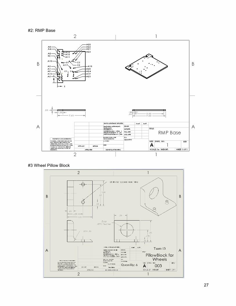
#2: RMP Base #3 Wheel Pillow Block

28
#4 Wheel
#5
Motor Pillow Block

29
#6 Wheel Axle #7 Bucket Support

30
#8 Jig [L] #9 Support Pillow Block

31
#10 Motor Axle #11 Bucket
#12

32
Bending Arm
#13 Support Axle

33
#14 Jig Housing [R]
#15 Jig [R]

34
#16 Front Axle
#17 Jig Support [L] #18

35
Pulley
#19 Jig Support [R] B.2.

36
Manufacturing plans Provide step-by-step manufacturing plans of all manufactured parts using the template below (the same as the one provided on CTools.) #1: Jig Housing [L]
Part Number: ME250-‐001 Revision Date: 11/13/2015 Part Name: Jig Housing (L) Team Name: Team 13 Raw Material Stock: Aluminum Square Tube 3/4"x3/4"x8.85", 1/8" Wall
Step # Process Description Machine Fixtures Tool(s) Speed (RPM)
1 Cut 9.1" long by Sliding part towards blade with wood
Band Saw vise -‐ 325 (FPM)
2 Mill one end of part .125" , just enough to provide a fully machined surface.
Mill vise 3/4 inch 2-‐flute endmill, collet
840
3 Remove part from vise. Break all edges by hand.
file
4 Turn part over and mill the other end .125 to bring to 8.85"
Mill Vise 3/4 inch 2-‐flute endmill, collet
840
5 Find datum lines in x,y,z Mill Edge finder, collet 900 6 Mill end 1" in x direction to cut out
slot. Mill Vise 1/4 inch 2-‐flute endmill,
collet 840
7 Mount part in vise with long dimension oriented vertically to mill out .25" x 1" square cut out.
Mill Vise 1/4 inch 2-‐flute endmill, collet
840
8 Remove part from vise. Break all edges by hand.
file
9 Mount part with long dimension oriented horizontally with slot facing down. Find datum lines in x,y,z.
Mill Vise Edge finder, collet 900
10 Peck drill to take out majority of material then run mill all the way down to clean the edges.
Mill Vise 1/4 inch 2-‐flute endmill, collet
840
11 Remove part from vise. Break all edges by hand.
file

37
#2: RMP Base
Part Number: ME250-‐002 Revision Date: 11/26/2015
Part Name: RMP Base Team Name: Team 13 Raw Material Stock: 1/4" Acrylic plate
Step # Process Description Machine Fixtures Tool(s) Speed (RPM)
1 Follow the Laser Cutter Operating Document
Laser Cutter
38
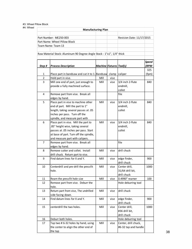
Part Number: ME250-‐003 Revision Date: 11/17/2015Part Name: Wheel Pillow BlockTeam Name: Team 13
Raw Material Stock: Aluminum 90 Degree Angle Stock -‐ 1"x1", 1/4" thick
Step # Process Description Machine Fixtures Tool(s)Speed(RPM
1 Place part in bandsaw and cut it to 1.25".Bandsaw clamp caliper325 (fpm)
2 Hold part in vise. Mill vise3 Mill one end of part, just enough to
provide a fully machined surface.Mill vise 3/4 inch 2-‐flute
endmill,collet
840
4 Remove part from vise. Break all edges by hand.
file
5 Place part in vise to machine other end of part. Mill the part to 1" length, taking several passes at .05 inches per pass. Turn off the spindle, and measure part with
Mill vise 3/4 inch 2-‐flute endmill,collet
840
6 Place part in vise. Mill the part to .85" height wise, taking several passes at .05 inches per pass. Start at base of part. Turn off the spindle, and measure part with calipers.
Mill vise 3/4 inch 2-‐flute endmill,collet
840
7 Remove part from vise. Break all edges by hand.
file
8 Remove cutter and collet. Install drill chuck. Return part to vise.
Mill vise drill chuck
9 Find datum lines for X and Y. Mill vise edge finder, drill chuck
900
10 Centerdrill and pre-‐drill the pressfit hole.
Mill vise Center drill,31/64 drill bit, drill chuck
1000
11 Ream the pressfit hole size Mill vise 0.4990" reamer 10012 Remove part from vise. Deburr the
hole.Hole deburring tool
13 Return part from vise, The undrilled side facing down.
Mill vise drill chuck
14 Find datum lines for X and Y. Mill vise edge finder, drill chuck
900
15 centerdrill the two holes. Mill vise Center drill,#36 drill bit, drill chuck
1000
16 Deburr both holes. Hole deburring tool17 Tap two # 6-‐32 holes by hand, using
the center to align the other end of the tap
Mill vise Center, drill chuck, #6-‐32 tap and handle
Manufacturing Plan
#3: Wheel Pillow Block #4: Wheel

39
Part Number: ME250-‐004 Revision Date: 12/16/2015
Part Name: Wheel Team Name: Team 13 Raw Material Stock: 1/4" Acrylic plate
Step # Process Description Machine Fixtures Tool(s) Speed (RPM)
1 Follow the Laser Cutter Operating Document
Laser Cutter
#5: Pillow Block for Motor Axle
Part Number: ME250-‐005 Revision Date: 11/5/2015
Part Name: Pillow Block Team Name: Team 13 Raw Material Stock: Aluminum 90 Degree Angle Stock -‐ 1"x1", 1/4" thick
Step # Process Description Machin
e Fixture
s Tool(s)
Speed (RPM)
1 Hold part in vise. Mill vise 2 Mill one end of part, just enough to provide a fully
machined surface. Mill vise 3/4 inch 2-‐flute endmill,
collet 500
3 Remove part from vise. Break all edges by hand. file 4 Place part in vise to machine other end of part. Mill
the part to 1" length, taking several passes at .05 inches per pass. Turn off the spindle, and measure part with calipers.
Mill vise 3/4 inch 2-‐flute endmill, collet
500
5 Remove part from vise. Break all edges by hand. file 6 Remove cutter and collet. Install drill chuck. Return
part to vise. Mill vise drill chuck
7 Find datum lines for X and Y for one hole on right side
view. Mill vise edge finder,
drill chuck 900
8 Centerdrill and pre-‐drill the hole. Mill vise Center drill, .125" drill bit, drill chuck
1600
9 Find datum lines for X and Y for second hole on right side view.
Mill vise edge finder, drill chuck
900
10 Centerdrill and pre-‐drill the hole. Mill vise Center drill, .125" drill bit, drill chuck
1600
11 Remove part from vise. Deburr the holes. Hole deburring tool

40
12 Return part to vise, rotated to have bottom view facing up.
Mill vise drill chuck
13 Find datum lines for X and Y for one of the holes on top view.
Mill vise edge finder, drill chuck
900
14 Centerdrill and pre-‐drill the hole. Mill vise Center drill, .125" drill bit, drill chuck
1600
15 Find datum lines for X and Y for second hole on right side view.
Mill vise edge finder, drill chuck
900
16 Centerdrill and pre-‐drill the hole. Mill vise Center drill, .125" drill bit, drill chuck
1600
17 Remove part from vise. Deburr the holes. Hole deburring tool 18 Tap two #6-‐32 holes by hand on top view holes, using
center to align the other end of the tap Mill vise Center, drill chuck, #6-‐
32 tap and handle

41
Part Number: ME250-‐006 Revision Date: 11/17/2015Part Name: Wheel Axle BackTeam Name: Team 13
Raw Material Stock: Aluminum Rod, 1" thick
Step # Process Description Machine Fixtures Tool(s)Speed(RPM)
1 Obtain part and place part on horizontal bandsaw.
Horizontal Bandsaw clamp
2 Measure 3.75" of the part and cut the piece.
Horizontal Bandsaw clamp Caliper
3 Remove part and break all edges by hand.
file
4 Hold part in the collet of Lathe. Lathe collet5 Lathe one end of part, just
enough to provide a fully machined surface.
Lathe collet Cutting tool
6 Remove part from collet. Break all edges by hand.
Lathe collet file
7 Place part in collet to machine other end of part. Lathe the part to 3.5" length, taking several passes at .02 inches per pass. Turn off the spindle, and measure part with calipers.
Lathe collet Cutting tool 750
9 Remove part from collet. Break all edges by hand.
file
10 Place part in collet. Start off from one end of the part. Lathe the part to .375" diameter for 3.375" of its length.
Lathe collet Cutting tool 300
11 Remove part from collet. Break all edges by hand.
file
12 Make one groove at the smaller diameter side of the axle.
Lathe collet groove tool 300
13 Remove part and flip it 180 degrees. Install piece back in the collet.
Lathe collet
14 Centerdrill one end and install live center.
Lathe collet drill chuck, center drill, live or dead center
750
15 Lathe other groove on part. Lathe collet groove tool, live or dead center
750
16 Take part to Mill and put the part in vise. Install drill chuck.
Mill vise drill chuck
17 Find datum lines for X and Y. Mill vise edge finder, drill chuck
900
18 Centerdrill and drill 4 small hole. Mill vise Center drill,#38 drill bit, drill chuck
1200
19 Remove part from collet and deburr the 4 holes.
deburring tool
20 Tap 4 # 5-‐40 holes by hand, using the center to align the other end of the tap
Mill vise Center, drill chuck, #5-‐40 tap and handle
Manufacturing Plan
#6: Wheel Axle
#7:
Bucket Support
[L]

42
Part Number: ME250-‐007 Revision Date: 12/16/2015
Part Name: Bucket Support [L] Team Name: Team 13 Raw Material Stock: 1/4" Acrylic plate
Step # Process Description Machine Fixtures Tool(s) Speed (RPM)
1 Follow the Water Jet Operating Document
Waterjet
#8: Jig [L]
Part Number: ME250-‐008 Revision Date: 5/16/2015
Part Name: Jig-‐L Team Name: Team 13 Raw Material Stock: Aluminum 1/2" square stock
Step # Process Description Machine Fixtures Tool(s) Speed (RPM)
1 Cut stock to 7.75" Bandsaw 325 (FPM) 2 Place in vice and Mill one end of part, just
enough to provide a fully machined surface.
Mill vise 3/4 inch endmill, collet
500
3 Remove part from vise. Break all edges by hand.
file
4 Place part in vise to machine other end of part. Mill the part to 7.5 length, taking several passes at .05 inches per pass. Turn off the spindle, and measure part with calipers.
Mill vise 3/4 inch endmill, collet
500
5 Remove part from vise. Break all edges by hand.
file
6 Mark the part to remove 7.5 x .29" of material out of the center.
Height Gauge, Surface Plate
7 Remove cutter and collet. Install new endmill and collet. Return part to vise.
Mill vise 1/4 inch endmill, collet
8 Place part in vise and use endmill to remove material making multiple passes going a depth of .24"
Mill vise 1/4 inch endmill, collet
1400
9 Mark the part to remove 7 x .29" of material out of the center.
Height Gauge, Surface Plate
10 Place part in vise and use endmill to remove material making multiple passes going a depth of .15" or a total depth of
Mill vise 1/4 inch endmill, collet
1400
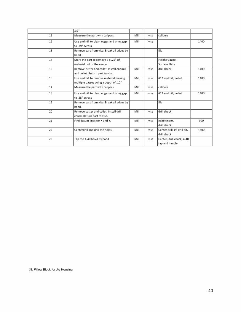
43
.39" 11 Measure the part with calipers. Mill vise calipers 12 Use endmill to clean edges and bring gap
to .29" across Mill vise
1400
13 Remove part from vise. Break all edges by hand.
file
14 Mark the part to remove 5 x .25" of material out of the center.
Height Gauge, Surface Plate
15 Remove cutter and collet. Install endmill and collet. Return part to vise.
Mill vise drill chuck 1400
16 Use endmill to remove material making multiple passes going a depth of .10"
Mill vise #12 endmill, collet 1400
17 Measure the part with calipers. Mill vise calipers 18 Use endmill to clean edges and bring gap
to .25" across Mill vise #12 endmill, collet 1400
19 Remove part from vise. Break all edges by hand.
file
20 Remove cutter and collet. Install drill chuck. Return part to vise.
Mill vise drill chuck
21 Find datum lines for X and Y. Mill vise edge finder, drill chuck
900
22 Centerdrill and drill the holes. Mill vise Center drill, #3 drill bit, drill chuck
1600
23 Tap the 4-‐40 holes by hand Mill vise Center, drill chuck, 4-‐40 tap and handle
#9: Pillow Block for Jig Housing

44
45
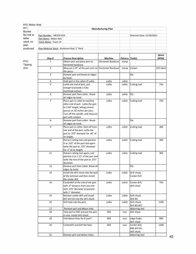
Part Number: ME250-‐010 Revision Date: 11/19/2015Part Name: Motor AxleTeam Name: Team 13
Raw Material Stock: Aluminum Rod, 1" thick
Step # Process Description Machine Fixtures Tool(s)Speed(RPM)
1 Obtain part and place part on horizontal bandsaw.
Horizontal Bandsaw clamp
2 Measure 2.25" of the part and cut the piece.
Horizontal Bandsaw clamp Caliper 325 (fpm)
3 Remove part and break all edges by hand.
file
4 Hold part in the collet of Lathe. Lathe collet5 Lathe one end of part, just
enough to provide a fully machined surface.
Lathe collet Cutting tool 750
6 Remove part from collet. Break all edges by hand.
Lathe collet file
7 Place part in collet to machine other end of part. Lathe the part to 2.00" length, taking several passes at .02 inches per pass. Turn off the spindle, and measure part with calipers.
Lathe collet Cutting tool 750
8 Remove part from collet. Break all edges by hand.
file
9 Place part in collet. Start off from one end of the part. Lathe the part to .375" diameter for .40" of its length.
Lathe collet Cutting tool 300
10 Retract cutting tool and position it at .525" of the part and again lathe the part to .375" diameter for .5" of its length.
Lathe collet Cutting tool 300
11 Retract cutting tool again, and position it at 1.15" of the part and lathe the rest of the part to .375" diameter.
Lathe collet Cutting tool 300
12 Remove part from collet. Break all edges by hand.
file
13 Install the drill chuck into the quill of the tailstock and then install the center drill.
Lathe collet Drill chuck, Center Drill
14 Centerdrill at the end of the part with .4" distance from one end with .375" diameter to position with 1" diameter.
Lathe collet Center drill,drill chuck
750
15 Remove center drill and install #27 drill bit into the drill chuck.
Lathe collet Drill chuck, Drill Bit
16 Drill hole into the part. Lathe collet Drill chuck, Drill Bit #27
1200
17 Remove part and deburr hole. deburring tool18 Take part to Mill and put the part
in vise. Install drill chuck. Mill vise drill chuck
19 Find datum lines for X and Y. Mill vise edge finder, drill chuck
900
20 Centerdrill and drill the hole. Mill vise Center drill,#48 drill bit, drill chuck
1200
21 Remove part and deburr holes. deburring tool
Manufacturing Plan
#10: Motor Axle #11: Bucket No mill or lathe used, no plan produced
#12: Tipping Arm

46
Part Number: ME250-‐013 Revision Date: 11/17/2015Part Name: Support AxleTeam Name: Team 13
Raw Material Stock: Carbon Steel Rod, 1/4"
Step # Process Description Machine Fixtures Tool(s)Speed(RPM)
1 Obtain part and place part on horizontal bandsaw.
Horizontal Bandsaw clamp
2 Measure 6.4" of the part and cut the piece.
Horizontal Bandsaw clamp Caliper
3 Remove part and break all edges by hand.
file
4 Hold part in the collet of Lathe. Lathe collet5 Lathe one end of part, just
enough to provide a fully machined surface.
Lathe collet Cutting tool
6 Remove part from collet. Break all edges by hand.
Lathe collet file
7 Place part in collet to machine other end of part. Lathe the part to 6.15" length, taking several passes at .02 inches per pass. Turn off the spindle, and measure part with calipers.
Lathe collet Cutting tool 750
8 Centerdrill one end of the part and hold it agaisnt a live center.
Lathe collet live center, centerdrill, drill chuck
750
9 Lathe 3 Grooves on part for E-‐clips placement.
Lathe collet Cutting tool 750
10 Remove part and flip it over and place it back in the collet.
Lathe collet
11 Turn the part for the final groove for the piece.
Lathe collet cutting tool 750
12 Remove part from collet. Break all edges by hand.
file
Manufacturing Plan
Part Number: ME250-‐012
Revision Date: 5/16/2015
Part Name: Tipping arm Team Name: Team 13 Raw Material Stock: 1/4" Acrylic plate
Step # Process Description Machine Fixtures Tool(s) Speed (RPM)
1 Follow the Laser Cutter Operating Document
Laser Cutter
#13: Support Axle
47
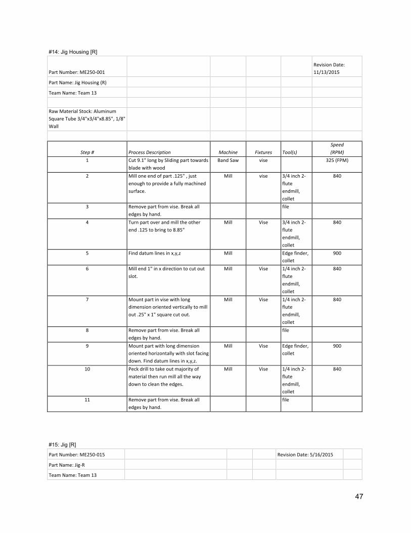
#14: Jig Housing [R]
Part Number: ME250-‐001 Revision Date: 11/13/2015
Part Name: Jig Housing (R) Team Name: Team 13 Raw Material Stock: Aluminum Square Tube 3/4"x3/4"x8.85", 1/8" Wall
Step # Process Description Machine Fixtures Tool(s) Speed (RPM)
1 Cut 9.1" long by Sliding part towards blade with wood
Band Saw vise 325 (FPM)
2 Mill one end of part .125" , just enough to provide a fully machined surface.
Mill vise 3/4 inch 2-‐flute endmill, collet
840
3 Remove part from vise. Break all edges by hand.
file
4 Turn part over and mill the other end .125 to bring to 8.85"
Mill Vise 3/4 inch 2-‐flute endmill, collet
840
5 Find datum lines in x,y,z Mill
Edge finder, collet
900
6 Mill end 1" in x direction to cut out slot.
Mill Vise 1/4 inch 2-‐flute endmill, collet
840
7 Mount part in vise with long dimension oriented vertically to mill out .25" x 1" square cut out.
Mill Vise 1/4 inch 2-‐flute endmill, collet
840
8 Remove part from vise. Break all edges by hand.
file
9 Mount part with long dimension oriented horizontally with slot facing down. Find datum lines in x,y,z.
Mill Vise Edge finder, collet
900
10 Peck drill to take out majority of material then run mill all the way down to clean the edges.
Mill Vise 1/4 inch 2-‐flute endmill, collet
840
11 Remove part from vise. Break all edges by hand.
file
#15: Jig [R] Part Number: ME250-‐015 Revision Date: 5/16/2015 Part Name: Jig-‐R Team Name: Team 13

48
Raw Material Stock: Aluminum 1/2" square stock
Step # Process Description Machine Fixtures Tool(s) Speed (RPM)
1 Cut stock to 7.75" Bandsaw 2 Place in vice and Mill one end of part, just
enough to provide a fully machined surface. Mill vise 3/4 inch endmill,
collet 500
3 Remove part from vise. Break all edges by hand.
file
4 Place part in vise to machine other end of part. Mill the part to 7.5 length, taking several passes at .05 inches per pass. Turn off the spindle, and measure part with calipers.
Mill vise 3/4 inch endmill, collet
500
5 Remove part from vise. Break all edges by hand.
file
6 Mark the part to remove 7.5 x .29" of material out of the center.
Height Gauge, Surface Plate
7 Remove cutter and collet. Install new endmill and collet. Return part to vise.
Mill vise 1/4 inch endmill, collet
8 Place part in vise and use endmill to remove material making multiple passes going a depth of .24"
Mill vise 1/4 inch endmill, collet
1400
9 Mark the part to remove 7 x .29" of material out of the center.
Height Gauge, Surface Plate
10 Place part in vise and use endmill to remove material making multiple passes going a depth of .15" or a total depth of .39"
Mill vise 1/4 inch endmill, collet
1400
11 Measure the part with calipers. Mill vise calipers 12 Use endmill to clean edges and bring gap to
.29" across Mill vise
1400
13 Remove part from vise. Break all edges by hand.
file
14 Mark the part to remove 5 x .25" of material out of the center.
Height Gauge, Surface Plate
15 Remove cutter and collet. Install endmill and collet. Return part to vise.
Mill vise drill chuck 1400
16 Use endmill to remove material making multiple passes going a depth of .10"
Mill vise #12 endmill, collet 1400
17 Measure the part with calipers. Mill vise calipers 18 Use endmill to clean edges and bring gap to
.25" across Mill vise #12 endmill, collet 1400
19 Remove part from vise. Break all edges by hand.
file
20 Remove cutter and collet. Install drill chuck. Return part to vise.
Mill vise drill chuck
21 Find datum lines for X and Y. Mill vise edge finder, drill chuck
900
22 Centerdrill and drill the holes. Mill vise Center drill, #3 drill bit, drill chuck
1600
23 Tap the 4-‐40 holes by hand Mill vise Center, drill chuck, 4-‐40 tap and handle

49
Part Number: ME250-‐016 Revision Date: 11/17/2015Part Name: Wheel Axle FrontTeam Name: Team 13
Raw Material Stock: Aluminum Rod, 1" thick
Step # Process Description Machine Fixtures Tool(s)Speed(RPM)
1 Obtain part and place part on horizontal bandsaw.
Horizontal Bandsaw clamp
2 Measure 3.9" of the part and cut the piece.
Horizontal Bandsaw clamp Caliper
3 Remove part and break all edges by hand.
file
4 Hold part in the collet of Lathe. Lathe collet5 Lathe one end of part, just
enough to provide a fully machined surface.
Lathe collet Cutting tool
6 Remove part from collet. Break all edges by hand.
Lathe collet file
7 Place part in collet to machine other end of part. Lathe the part to 3.65" length, taking several passes at .02 inches per pass. Turn off the spindle, and measure part with calipers.
Lathe collet Cutting tool 750
8 Remove part from collet. Break all edges by hand.
file
9 Place part in collet. Start off from one end of the part. Lathe the part to .375" diameter for 3.525" of its length.
Lathe collet Cutting tool 300
10 Make one groove at the smaller diameter side of the axle.
Lathe collet groove tool 300
11 Remove part and flip it 180 degrees. Install piece back in the collet.
Lathe collet
12 Centerdrill one end and install live center.
Lathe collet drill chuck, center drill, live or dead center
750
13 Lathe other groove on part. Lathe collet groove tool, live or dead center
750
14 Remove part from collet. Break all edges by hand.
file
15 Place part back into collet of Lathe.
Lathe collet
16 Install the drill chuck into the quill of the tailstock and then install the center drill.
Lathe collet Drill chuck, Center Drill
17 Centerdrill at the end of the part with .375" diameter.
Lathe collet Center drill,drill chuck
750
18 Remove center drill and install #30 drill bit into the drill chuck.
Lathe collet Drill chuck, Drill Bit #30
19 Drill hole into the part. Lathe collet Drill chuck, Drill Bit #30
2000
20 Remove part and deburr hole. deburring tool21 Take part to Mill and put the part
in vise. Install drill chuck. Mill vise drill chuck
22 Find datum lines for X and Y. Mill vise edge finder, drill chuck
900
23 Centerdrill and drill 4 small hole. Mill vise Center drill,#38 drill bit, drill chuck
1200
24 Remove part and deburr holes. deburring tool25 Place part back in the vise, but
orient it so you could drill a hole perpendicular to the hole made at the lathe.
Mill vise drill chuck
26 Find datum lines for X and Y. Mill vise edge finder, drill chuck
900
27 Centerdrill and drill the hole. Mill vise Center drill,#52 drill bit, drill chuck
1200
28 Remove part and deburr holes. deburring tool29 Tap 4 # 5-‐40 holes by hand, using
the center to align the other end of the tap
Mill vise Center, drill chuck, #5-‐40 tap and handle
Manufacturing Plan
#16: Front Axle

50
Part Number: ME250-‐007 Revision Date: 11/17/2015Part Name: Bucket Support [L]Team Name: Team 13
Raw Material Stock: 1/4" Thick Aluminum Plate
Step # Process Description Machine Fixtures Tool(s)Speed(RPM)
1 Cut two rectangular pieces 1.13" x .50" long by Sliding part towards blade with wood
Band Saw vise -‐ 325( FPM)
2 Clamp part in vise with top face up. Mill one end of part .125" , just enough to provide a fully machined surface.
Mill vise 3/4 inch 2-‐flute endmill,collet
500
3 Remove part from vise. Break all edges by hand.
file
4 Turn part over and mill the other end .125" and bring to .88"
Mill Vise 3/4 inch 2-‐flute endmill,collet
500
5 Remove part from vise. Break all edges by hand.
file
6 Clamp part in vise with right face up. Mill one end of part .125" , just enough to provide a fully machined surface.
Mill vise 3/4 inch 2-‐flute endmill,collet
500
7 Remove part from vise. Break all edges by hand.
file
8 Turn part over and mill the other end .125,and bring to .88"
Mill Vise 3/4 inch 2-‐flute endmill,collet
500
9 Remove part from vise. Break all edges by hand.
file
10 Return part to vise and find datum lines in x,y
Mill Vise Edge finder, collet 900
11 Center drill through part. Mill Vise Center drill, #30 drill bit, drill chuck
1600
12 Flip part and find datum lines in x,y
Mill Vise Edge finder, collet 900
13 Center drill through part. Mill Vise Center drill, # 43 drill bit, drill chuck
1600
14 Tap the 4-‐40 holes by hand, using the center to align the other end of the tap.
Mill vise Center,drill chuck, 4-‐40 tap and handle
15 Remove part from vise. Deburr holes.
deburring tool
16 Mark the part to remove .125 x .495 of material.
Height Gauge, Surface Plate, edgefinder, collet
17 Place part in vise and use endmill to remove material. Turn off the spindle, and measure part with calipers.
Mill vise 3/4 inch 2-‐flute endmill,collet
500
18 Remove part from vise. Break all edges by hand.
file
Manufacturing Plan
#17
Jig
Support [L]

51
#18: Pulley Part Number: ME250-‐018
Revision Date: 11/18/2015
Part Name: Pulley Team Name: Team 13 Raw Material Stock: Aluminum Round Stock ¾” x 8”
Step # Process Description Machine Fixtures Tool(s) Speed(RPM)
1 Cut to 1" long: slide part towards blade with wood Band Saw Vise 325 (FPM)
2 Remove part from vise. Deburr all edges file
3 Place stock in collet and lock into lathe Lathe Collet 4 Surface circular cross section Lathe Collet cutting tool, oil 750
5 Unlock headstock, remove collet, remove part and deburr edges file
6 Measure part, flip part horizontally, reinsert into collet, lock collet into lathe Lathe Collet calipers
7 Surface cylindrical cross section Lathe Collet cutting tool, oil 750
8 Install drill chuck, use center drill to make small hole in end Lathe
Collet, drill chuck center drill #3 750
9 Remove drill chuck, insert live center and use to support end of stock Lathe
collet, drill chuck live center
10 Touch turning tool to edges of material to find datum lines in x and y Lathe Collet cutting tool, oil 750
11 Cut slot for string into center Lathe Collet groove tool, oil 750
12 Remove live center, install drill chuck, insert 11/32”bit, peck drill through part Lathe
Collet, drill chuck 11/32” bit 750
13 Install .3740” reamer into drill chuck; peck drill through entire part Lathe
Collet, drill chuck
.3740” reamer, cutting oil 750
14
Flip part then slowly take cylindrical height down to 0.3”, adjusting % inside collet as necessary Lathe Collet cutting tool, oil 750
15 Remove part from vise. Deburr all edges file
16 Deburr holes deburring tool
17 Clean work station and return the tools to tool crib

52
#19: Jig Support [R]

53
C. PURCHASED AND TRADED ITEMS C.1 Purchased parts Include the vendor, part name/number, price, a brief description of the need/use, and calculate the total price of all purchased parts.
Supplier Part name/number Dimensions Total quantity
Price Description
McMaster Flanged Brass Bushing (2938T6)
3/8th” ID, ½” OD
7 $5.60 Place in pillow blocks used to mount wheel axles. Also placed in pulley
Home Depot
26 Guage Flashing 1’ X 2’ 1 $2.23 Used to make the bucket
Home Depot
Aluminum Rod 1/8 Dia. 9” length
1 $2.12 Pin for bucket
Total $9.95
C.2. Traded parts (inter-squad) Include traded parts, the other team’s #, positive trade deficits (if trade-in price larger than trade-out) and a brief description of the need/use. Calculate the total of trade deficits.
Trade-in part Trade-out part(s)
From Positive Trade
Deficits
Description
N/A N/A N/A N/A N/A
Related Documents