ROBOSTAR ROBOT N1 Series INSTRUCTION MANUAL INSTRUCTION MANUAL OPERATION MANUAL PROGRAMMING MANUAL UNI-HOST MANUAL GAIN SETUP MANUAL ALARM CODE MANUAL √ www.robostar.co.kr Robostar Co., Ltd. Robostar Robot Controller Manual

Welcome message from author
This document is posted to help you gain knowledge. Please leave a comment to let me know what you think about it! Share it to your friends and learn new things together.
Transcript
ROBOSTAR ROBOT
N1 Series
INSTRUCTION MANUAL
INSTRUCTION MANUAL
OPERATION MANUAL
PROGRAMMING MANUAL
UNI-HOST MANUAL
GAIN SETUP MANUAL
ALARM CODE MANUAL
√
www.robostar.co.kr
Robostar Co., Ltd.
Robostar Robot Controller Manual

Copyright ROBOSTAR Co,. Ltd 2012
Copyright of this instruction manual is reserved to Robostar Co., Ltd.
Any part of this manual cannot be used as other forms or other means without permission of Robostar.
The specifications are subject to change without notice in advance.
About Product Warranty
i Robostar Co., Ltd.
About Product Warranty
Products of Robostar Co., Ltd. are manufactured under the strict quality control. All the
Robostar products’ warranty period is one year from the date of manufacture. During this
period, Robostar is only responsible for the mechanical failures due to negligence of Robostar,
or the problems on design and manufacture occurring during normal use, in which the
service is free of charge. However, the service is not free of charge service in the following
cases:
(1) after the warranty period has expired
(2) failures arising due to improper repair, alteration, redeployment, or other mishandling,
under the instruction of you or any third party
(3) failures as a result of using parts, grease, etc. which have not been designated by
Robostar
(4) failures caused by accidents, such as fire, disaster, earthquake, storms, or other natural
disasters
(5) failures caused in manure, flooding, or other environment
(6) failure caused by the consumption of consumable parts
(7) failures arising when not being operated under the instructions listed in the user or
instruction manual and the maintenance manual
(8) damages in cost other than the cost of robot repairing
Address and contact points of Robostar Robostar Co., Ltd.
Head Office & Factory
119-38, Sasa-dong, Sangnok-gu,
Ansan-City, Gyeonggi-do, Republic of
Korea (426-220)
2nd Factory
960, Gosaek-dong, Gwonseon-gu,
Suwon-City, Gyeonggi-do, Republic of
Korea (441-813)
Request for service and Inquiry
of products
- Information on Marketing
TEL. 031-400-3600
FAX. 031-419-4249
- Customer Service
TEL. 1588-4428
www.robostar.co.kr
About Product Warranty
ii Robostar Co., Ltd.
For Safe Use
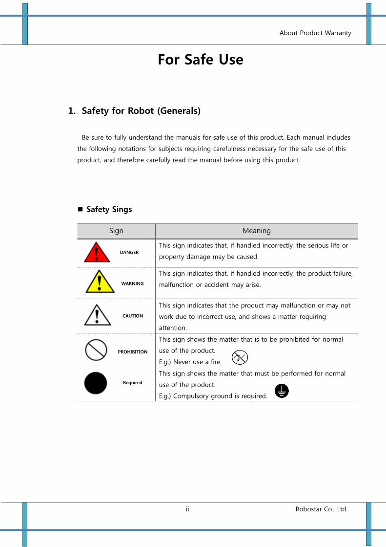
1. Safety for Robot (Generals)
Be sure to fully understand the manuals for safe use of this product. Each manual includes
the following notations for subjects requiring carefulness necessary for the safe use of this
product, and therefore carefully read the manual before using this product.
Safety Sings
Sign Meaning
This sign indicates that, if handled incorrectly, the serious life or
property damage may be caused.
This sign indicates that, if handled incorrectly, the product failure,
malfunction or accident may arise.
This sign indicates that the product may malfunction or may not
work due to incorrect use, and shows a matter requiring
attention.
This sign shows the matter that is to be prohibited for normal
use of the product.
E.g.) Never use a fire.
This sign shows the matter that must be performed for normal
use of the product.
E.g.) Compulsory ground is required.
DANGER
WARNING
CAUTION
PROHIBITION
Required
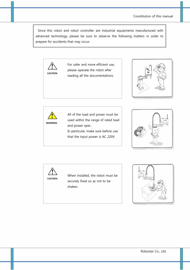
Constitution of this manual
Robostar Co., Ltd.
For safer and more efficient use,
please operate the robot after
reading all the documentations.
All of the load and power must be
used within the range of rated load
and power spec.
In particular, make sure before use
that the input power is AC 220V.
When installed, the robot must be
securely fixed so as not to be
shaken.
CAUTION
WARNING
CAUTION
Since this robot and robot controller are industrial equipments manufactured with
advanced technology, please be sure to observe the following matters in order to
prepare for accidents that may occur.
Constitution of this manual
Robostar Co., Ltd.
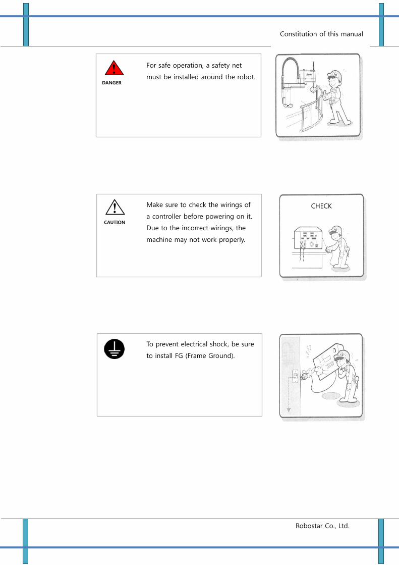
For safe operation, a safety net
must be installed around the robot.
Make sure to check the wirings of
a controller before powering on it.
Due to the incorrect wirings, the
machine may not work properly.
To prevent electrical shock, be sure
to install FG (Frame Ground).
DANGER
CAUTION
CHECK
Constitution of this manual
Robostar Co., Ltd.
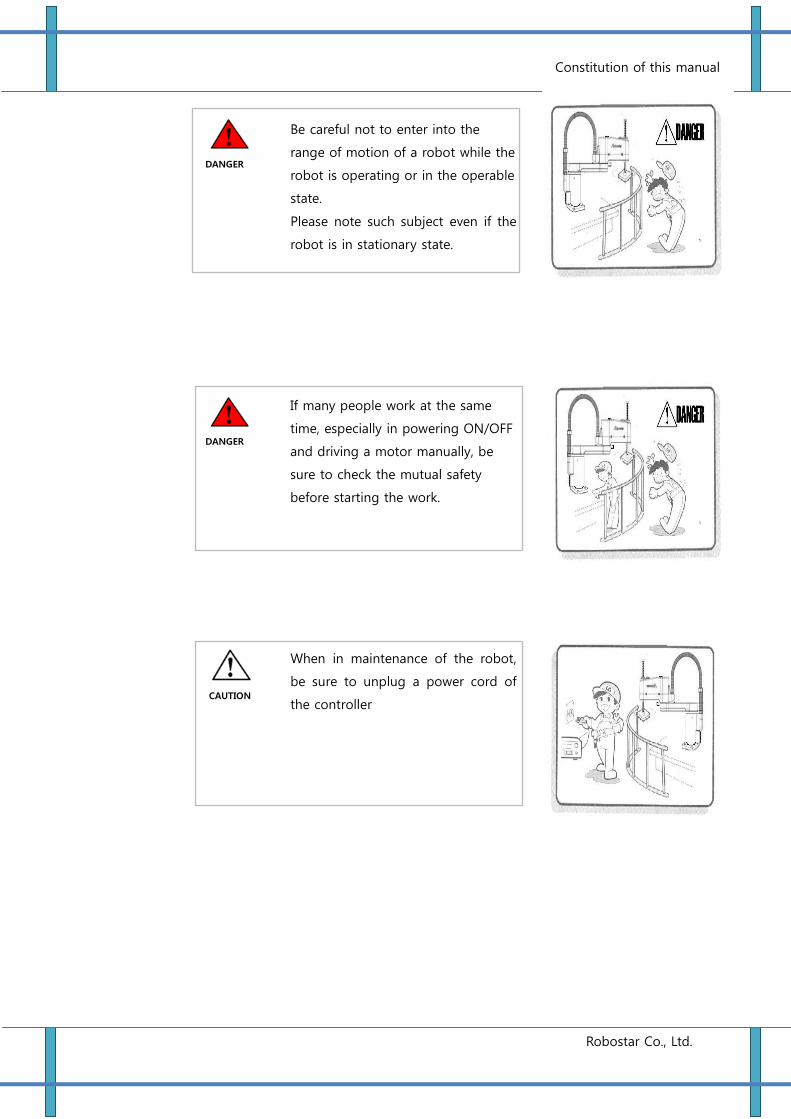
Be careful not to enter into the
range of motion of a robot while the
robot is operating or in the operable
state.
Please note such subject even if the
robot is in stationary state.
If many people work at the same
time, especially in powering ON/OFF
and driving a motor manually, be
sure to check the mutual safety
before starting the work.
When in maintenance of the robot,
be sure to unplug a power cord of
the controller
DANGER
CAUTION
DANGER
Constitution of this manual
Robostar Co., Ltd.
2. Safety for Robot (Details)
1) For the safety of workers, be sure to wear a helmet, safety shoes, etc.
2) Before powering ON, checke that there is no people within the area of robot motion
and then operate the robot.
3) When entering into the area of the robot motion for maintenance or inspection, be
sure to power OFF the robot.
4) If a cable of the robot is installed in a pathway, prevent the cable from damage by
using a cover or a duct.
5) As soon as the cable damage is found, replace it immediately.
6) Do not operate the robot under the load exceeding nominal weight.
7) Be sure to fully understand the instruction manual before operating the robot.
8) In the case of installing a safety net:
① Give it sufficient strength to withstand reactions that occur during work, or
environmental conditions, and do not have it be easily moved, destroyed, or
climbed.
② Remove the dangerous parts, such as sharp edges or burr.
③ Firmly fix it.
④ If you are installing a safety net having a door, install a detector or other sensors
so that the robot is stopped immediately after the door is opened.
⑤ The safety net must be distanced by 40 cm or farther from robot motion area
and the robot body.
Constitution of this manual
Robostar Co., Ltd.
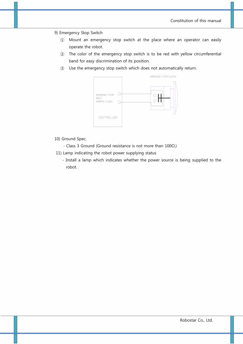
9) Emergency Stop Switch
① Mount an emergency stop switch at the place where an operator can easily
operate the robot.
② The color of the emergency stop switch is to be red with yellow circumferential
band for easy discrimination of its position.
③ Use the emergency stop switch which does not automatically return.
10) Ground Spec.
- Class 3 Ground (Ground resistance is not more than 100Ω.)
11) Lamp indicating the robot power supplying status
- Install a lamp which indicates whether the power source is being supplied to the
robot.
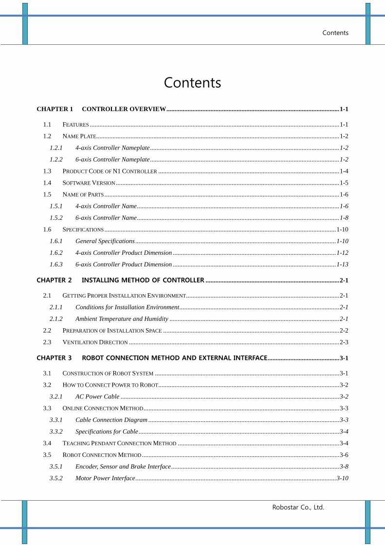
Contents
Robostar Co., Ltd.
Contents
CHAPTER 1 CONTROLLER OVERVIEW .......................................................................................................... 1-1
1.1 FEATURES ......................................................................................................................................................... 1-1
1.2 NAME PLATE..................................................................................................................................................... 1-2
1.2.1 4-axis Controller Nameplate .................................................................................................................... 1-2
1.2.2 6-axis Controller Nameplate .................................................................................................................... 1-2
1.3 PRODUCT CODE OF N1 CONTROLLER ............................................................................................................... 1-4
1.4 SOFTWARE VERSION ......................................................................................................................................... 1-5
1.5 NAME OF PARTS ................................................................................................................................................ 1-6
1.5.1 4-axis Controller Name ............................................................................................................................ 1-6
1.5.2 6-axis Controller Name ............................................................................................................................ 1-8
1.6 SPECIFICATIONS .............................................................................................................................................. 1-10
1.6.1 General Specifications ........................................................................................................................... 1-10
1.6.2 4-axis Controller Product Dimension .................................................................................................... 1-12
1.6.3 6-axis Controller Product Dimension .................................................................................................... 1-13
CHAPTER 2 INSTALLING METHOD OF CONTROLLER .................................................................................. 2-1
2.1 GETTING PROPER INSTALLATION ENVIRONMENT.............................................................................................. 2-1
2.1.1 Conditions for Installation Environment .................................................................................................. 2-1
2.1.2 Ambient Temperature and Humidity ........................................................................................................ 2-1
2.2 PREPARATION OF INSTALLATION SPACE ............................................................................................................ 2-2
2.3 VENTILATION DIRECTION ................................................................................................................................. 2-3
CHAPTER 3 ROBOT CONNECTION METHOD AND EXTERNAL INTERFACE ............................................ 3-1
3.1 CONSTRUCTION OF ROBOT SYSTEM ................................................................................................................. 3-1
3.2 HOW TO CONNECT POWER TO ROBOT ............................................................................................................... 3-2
3.2.1 AC Power Cable ...................................................................................................................................... 3-2
3.3 ONLINE CONNECTION METHOD ........................................................................................................................ 3-3
3.3.1 Cable Connection Diagram ..................................................................................................................... 3-3
3.3.2 Specifications for Cable ........................................................................................................................... 3-4
3.4 TEACHING PENDANT CONNECTION METHOD ................................................................................................... 3-4
3.5 ROBOT CONNECTION METHOD ......................................................................................................................... 3-6
3.5.1 Encoder, Sensor and Brake Interface ....................................................................................................... 3-8
3.5.2 Motor Power Interface ........................................................................................................................... 3-10
Contents
Robostar Co., Ltd.
3.6 IN/OUT CONNECTION METHOD ...................................................................................................................... 3-11
3.6.1 I/O Assignment ....................................................................................................................................... 3-11
3.6.2 I/O Spec. ................................................................................................................................................ 3-11
3.6.3 I/O Interface (Standard I/O) .................................................................................................................. 3-12
3.6.4 Functions of System I/O ......................................................................................................................... 3-13
3.6.5 System I/O Circuit Diagram................................................................................................................... 3-16
3.6.5.1 N-TYPE System I/O Circuit Diagram (Input: PCOM, Output: NCOM) ............................................................ 3-16
3.6.5.2 P-TYPE System I/O Circuit Diagram (Input: NCOM, Output: PCOM) ............................................................. 3-17
3.6.6 Connector Configuration & Circuit Diagram of User I/0 ..................................................................... 3-22
3.6.7 Input/Output Circuit Diagram for USER I/O ......................................................................................... 3-24
3.6.7.1 N-TYPE USER I/O Circuit Diagram (Input: PCOM, Output: NCOM) .............................................................. 3-24
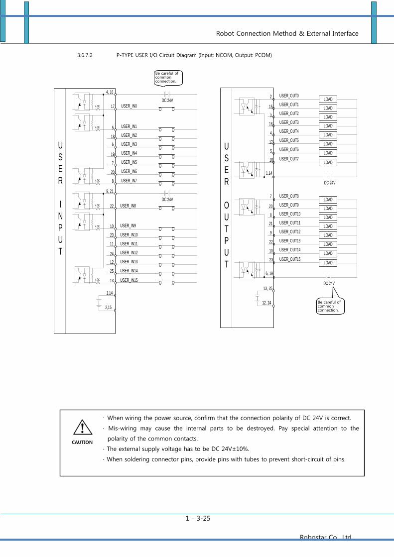
3.6.7.2 P-TYPE USER I/O Circuit Diagram (Input: NCOM, Output: PCOM) .............................................................. 3-25
3.6.8 Extended USER I/O Interface ................................................................................................................ 3-26
3.6.9 Extended USER I/O Connector Configuration & Circuit Diagram ....................................................... 3-27
3.6.10 Extended USER I/O Circuit Diagram .................................................................................................... 3-29
3.6.10.1 N-TYPE Extended USER I/O Circuit Diagram (Input: PCOM, Output: NCOM) .............................................. 3-29
3.6.10.2 P-TYPE Extended USER I/O Circuit Diagram (Input: NCOM, Output: PCOM) ............................................... 3-30
3.6.11 I/O Connection Checking ....................................................................................................................... 3-31
3.7 EMERGENCY STOP CIRCUIT WIRING ............................................................................................................... 3-41
CHAPTER 4 ABOUT TEACHING PENDANT ...................................................................................................... 4-1
4.1 CONNECTION OF TEACHING PENDANT .............................................................................................................. 4-1
4.1.1 Connection to controller .......................................................................................................................... 4-1
4.1.2 Using Controller without Teaching Pendant ............................................................................................ 4-2
4.2 EXTERIOR APPERANCE & MANIPULATION METHOD ......................................................................................... 4-3
4.2.1 Exterior Apperance & manipulation keys ................................................................................................ 4-3
4.2.2 Function of Manipulation Keys................................................................................................................ 4-5
4.2.3 Deadman Switch ...................................................................................................................................... 4-9
CHAPTER 5 CONTROLLER ALARM CODE TABLE ..................................................................................... 5-10
5.1 FILE SYSTEM ALARMS .................................................................................................................................... 5-10
5.2 PROTECTIVE ALARMS ..................................................................................................................................... 5-10
5.3 RUN TIME ALARMS ......................................................................................................................................... 5-11
5.4 JOB COMPILE ALARMS .................................................................................................................................... 5-12
5.5 TRAJECTORY ALARMS .................................................................................................................................... 5-12
5.6 COMMUNICATON ...................................................................................................................................... 5-13
5.7 SERVO AMP ................................................................................................................................................. 5-14
5.8 ENCODER .................................................................................................................................................... 5-16
Contents
Robostar Co., Ltd.
5.9 SV_MEMORY .............................................................................................................................................. 5-18
Controller Overview
1-1 Robostar Co., Ltd.
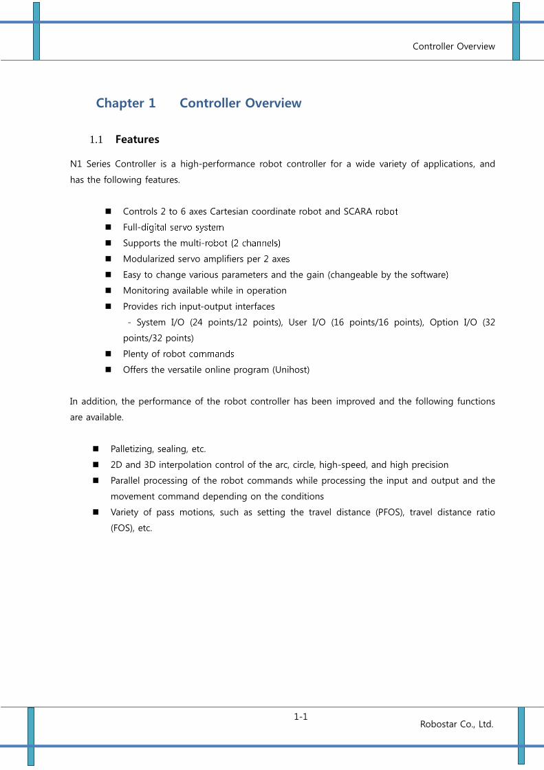
Chapter 1 Controller Overview
1.1 Features
N1 Series Controller is a high-performance robot controller for a wide variety of applications, and
has the following features.
Controls 2 to 6 axes Cartesian coordinate robot and SCARA r
Full-d
Supports the multi-r
Modularized servo amplifiers per 2 axe
Easy to change various parameters and the gain (changeable by the software
Monitoring available while in operation
Provides rich input-output interfaces
- System I/O (24 points/12 points), User I/O (16 points/16 points), Option I/O (32
points/32 points)
Plenty of robot
Offers the versatile online program (Unihost)
In addition, the performance of the robot controller has been improved and the following functions
are available.
Palletizing, sealing, etc.
2D and 3D interpolation control of the arc, circle, high-speed, and high precision
Parallel processing of the robot commands while processing the input and output and the
movement command depending on the conditions
Variety of pass motions, such as setting the travel distance (PFOS), travel distance ratio
(FOS), etc.
Controller Overview
1-2 Robostar Co., Ltd.
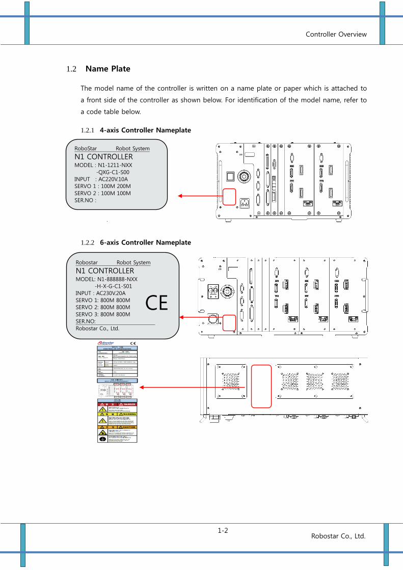
1.2 Name Plate
The model name of the controller is written on a name plate or paper which is attached to
a front side of the controller as shown below. For identification of the model name, refer to
a code table below.
1.2.1 4-axis Controller Nameplate
1.2.2 6-axis Controller Nameplate
Robostar Robot System
N1 CONTROLLER MODEL: N1-888888-NXX
-H-X-G-C1-S01
INPUT : AC230V.20A
SERVO 1: 800M 800M
SERVO 2: 800M 800M
SERVO 3: 800M 800M
SER.NO:
Robostar Co., Ltd.
CE
RoboStar Robot System
N1 CONTROLLER MODEL : N1-1211-NXX
-QXG-C1-S00
INPUT : AC220V.10A
SERVO 1 : 100M 200M
SERVO 2 : 100M 100M
SER.NO :
Robostar Co.Ltd.
Controller Overview
1-3 Robostar Co., Ltd.
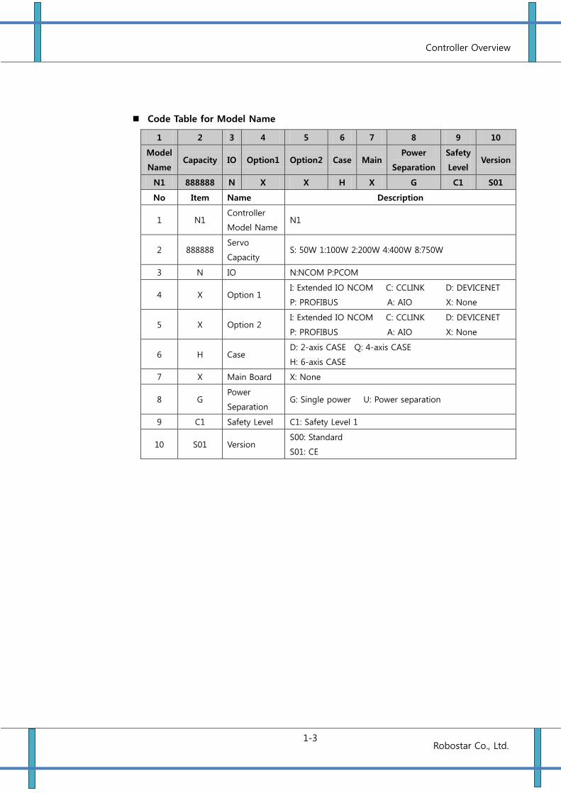
Code Table for Model Name
1 2 3 4 5 6 7 8 9 10
Model
Name Capacity IO Option1 Option2 Case Main
Power
Separation
Safety
Level Version
N1 888888 N X X H X G C1 S01
No Item Name Description
1 N1 Controller
Model Name N1
2 888888 Servo
Capacity S: 50W 1:100W 2:200W 4:400W 8:750W
3 N IO N:NCOM P:PCOM
4 X Option 1 I: Extended IO NCOM C: CCLINK D: DEVICENET
P: PROFIBUS R:RT A: AIO X: None
5 X Option 2 I: Extended IO NCOM C: CCLINK D: DEVICENET
P: PROFIBUS R:RT A: AIO X: None
6 H Case D: 2-axis CASE Q: 4-axis CASE
H: 6-axis CASE R: RTEX
7 X Main Board X: None
8 G Power
Separation G: Single power U: Power separation
9 C1 Safety Level C1: Safety Level 1 C3: 안전등급 4
10 S01 Version S00: StandardD00: DE
S01: CE
Controller Overview
1-4 Robostar Co., Ltd.
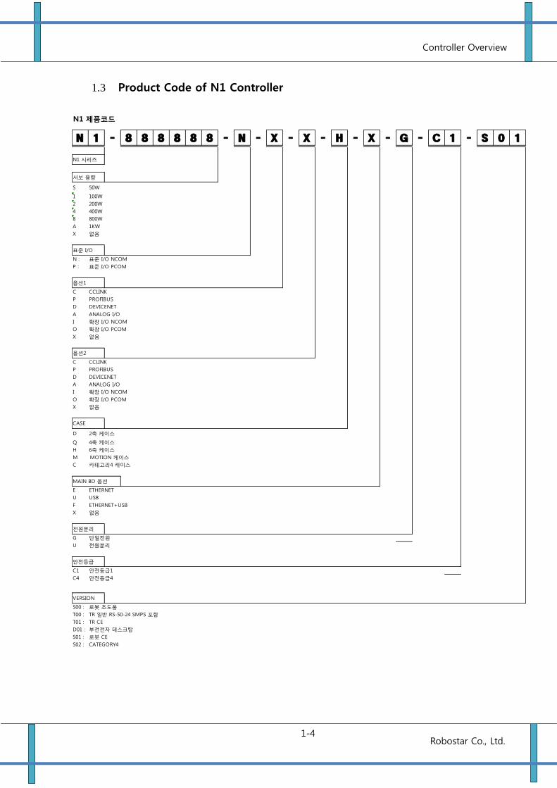
1.3 Product Code of N1 Controller
N1 제품코드
N 1 - 8 8 8 8 8 8 - N - X - X - H - X - G - C 1 - S 0 1
N1 시리즈
서보 용량
S 50W
1 100W
2 200W
4 400W
8 800W
A 1KW
X 없음
표준 I/O
N : 표준 I/O NCOM
P : 표준 I/O PCOM
옵션1
C CCLINK
P PROFIBUS
D DEVICENET
A ANALOG I/O
I 확장 I/O NCOM
O 확장 I/O PCOM
X 없음
옵션2
C CCLINK
P PROFIBUS
D DEVICENET
A ANALOG I/O
I 확장 I/O NCOM
O 확장 I/O PCOM
X 없음
CASE
D 2축 케이스
Q 4축 케이스
H 6축 케이스
M MOTION 케이스
C 카테고리4 케이스
MAIN BD 옵션
E ETHERNET
U USB
F ETHERNET+USB
X 없음
전원분리
G 단일전원
U 전원분리
안전등급
C1 안전등급1
C4 안전등급4
VERSION
S00 : 로봇 초도품
T00 : TR 일반 RS-50-24 SMPS 포함
T01 : TR CE
D01 : 부전전자 데스크탑
S01 : 로봇 CE
S02 : CATEGORY4
Controller Overview
1-5 Robostar Co., Ltd.
F4
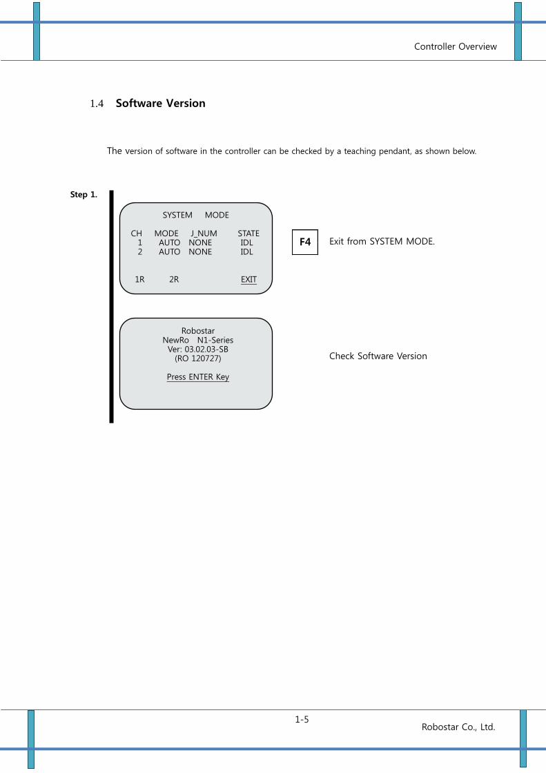
1.4 Software Version
The version of software in the controller can be checked by a teaching pendant, as shown below.
Step 1.
Exit from SYSTEM MODE.
SYSTEM MODE CH MODE J_NUM STATE
1 AUTO NONE IDL 2 AUTO NONE IDL
1R 2R EXIT
Robostar NewRo N1-Series Ver: 03.02.03-SB
(RO 120727)
Press ENTER Key
Check Software Version
Controller Overview
1-6 Robostar Co., Ltd.
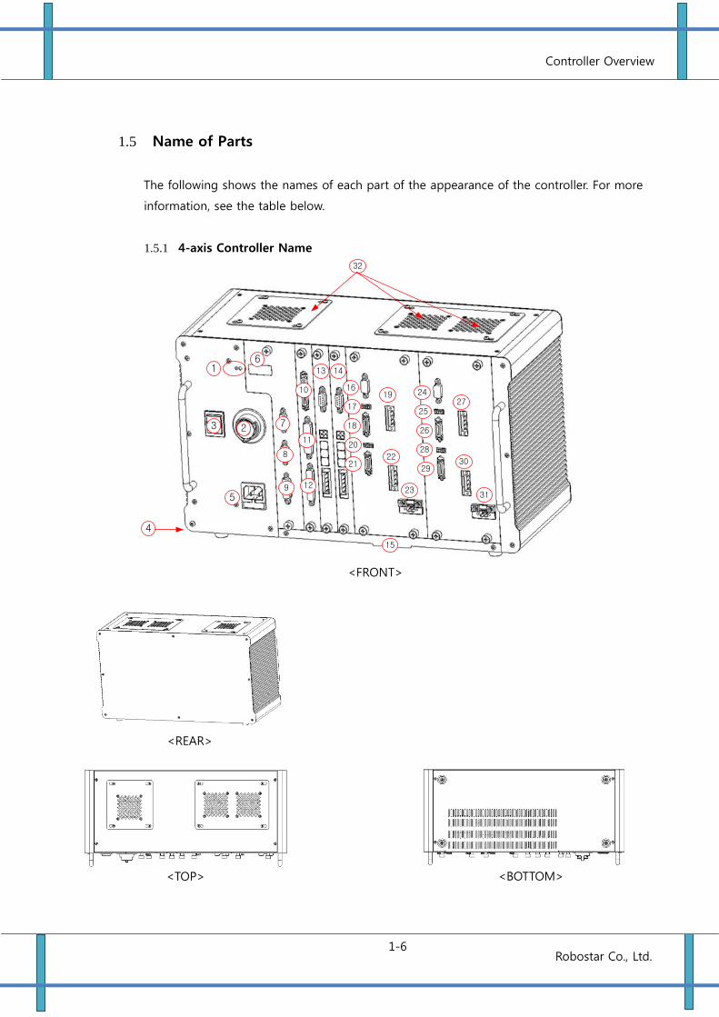
1.5 Name of Parts
The following shows the names of each part of the appearance of the controller. For more
information, see the table below.
1.5.1 4-axis Controller Name
4
5
3 2
16
7
8
9
10
11
12
13 14
16
21
17
22
18
19
23
20
24
25
26
27
28
15
32
30
31
29
<TOP>
<BOTTOM>
<FRONT>
<REAR>
Controller Overview
1-7 Robostar Co., Ltd.
커넥터 설명
Connector No. Exterior Marking Description
1 5V / 24V SMPS Status Indication
2 EMERGENCY Robot Emergency Stop Button
3 POWER(ON/OFF) AC Power Input Switch
4
FG (Frame Ground) Connection Terminal
5 AC 220V AC Power Input Connector(FUSE 10A)
6 7-Segment Status Indicating 7-Segment
7 MPG/485 MPG Connection Connector
8 HOST Unihost Connection Connector
9 T/P Teaching Pendant Connection Connector
10 SYSTEM IN/OUT SYSTEM I/O Connector
11 USER OUTPUT USER OUT Connector
12 USER INPUT USER IN Connector
13 OPTION B/D 1 Connection Slot for Option I/O, Field Bus, Analog Board,
etc.
14 OPTION B/D 2 Connection Slot for Option I/O, Field Bus, Analog Board,
etc.
15 FILTER Air Intake Filter
16 EXT IO Servo Module Update & Monitoring (No.1 & 2 axis)
17 AL/RD/SV/POW Servo Module Status Indication (No. 1 axis)
18 ENC #1 Encoder Input Connector (No. 1 axis)
18 U V W FG Motor Power Output Connector (No. 1 axis)
20 AL/RD/SV/POW Servo Module Status Indication
21 ENC #2 Encoder Input Connector (No.2 axis)
22 U V W FG Motor Power Output Connector (No.2 axis)
23 PB Regenerative Resistor Connector (1, 2 axis)
24 EXT IO Servo Module Update & Monitoring (No.3 & 4 axis)
25 AL/RD/SV/POW Servo Module Status Indication (No. 3 axis)
26 ENC #3 Encoder Input Connector (No. 3 axis)
27 U V W FG Motor Power Output Connector (No. 3 axis)
28 AL/RD/SV/POW Servo Module Status Indication(No. 4 axis)
29 ENC #4 Encoder Input Connector (No.4 axis)
30 U V W FG Motor Power Output Connector (No.4 axis)
31 PB Regenerative Resistor Connector (3, 4 axis)
32 Fan Air Exhaust Fan
Controller Overview
1-8 Robostar Co., Ltd.
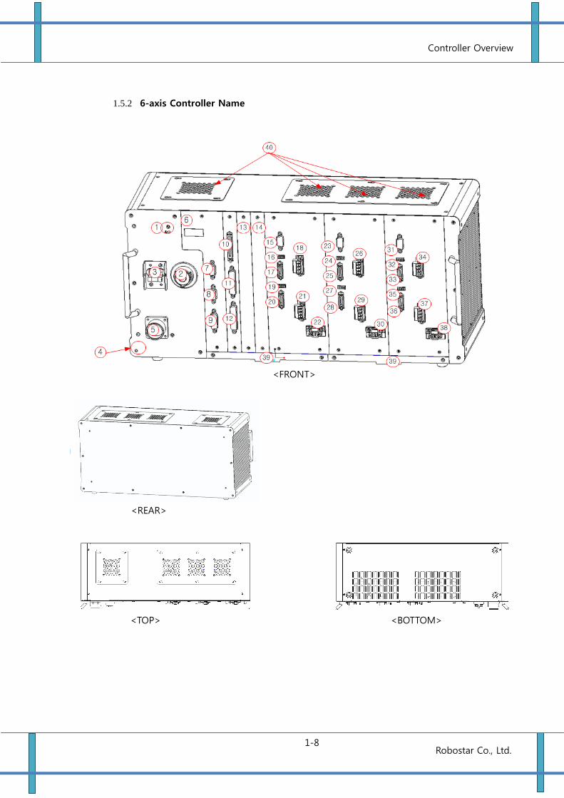
1.5.2 6-axis Controller Name
<TOP> <BOTTOM>
<FRONT>
<REAR>
Controller Overview
1-9 Robostar Co., Ltd.
Description of Connectors
Connector No. Exterior Marking Description
1 5V/24V SMPS Status Indication
2 EMERGENCY Robot Emergency Stop Button
3 POWER(ON/OFF) AC Power Input Switch
4
FG (Frame Ground) Connection Terminal
5 AC 220V AC Power Input Connector(FUSE 10A)
6 7-Segment Status Indicating 7-Segment
7 MPG/485 MPG Connection Connector
8 HOST Unihost Connection Connector
9 T/P Teaching Pendant Connection Connector
10 SYSTEM I/O SYSTEM I/O Connector
11 USER OUTPUT USER OUT Connector
12 USER INPUT USER IN Connector
13 OPTION BOARD 1 Connection Slot for Option I/O, Field Bus, Analog Board, etc.
14 OPTION BOARD 2 Connection Slot for Option I/O, Field Bus, Analog Board, etc.
15 EXT IO Servo Module Update & Monitoring (No.1 & 2 axis)
16 AL/RD/SV/POW Servo Module Status Indication (No. 1 axis)
17 ENC #1 Encoder Input Connector (No. 1 axis)
18 U V W FG Motor Power Output Connector (No. 1 axis)
18 AL/RD/SV/POW Servo Module Status Indication
20 ENC #2 Encoder Input Connector (No.2 axis)
21 U V W FG Motor Power Output Connector (No.2 axis)
22 PB Regenerative Resistor Connector (1, 2 axis)
23 EXT IO Servo Module Update & Monitoring (No.3 & 4 axis)
24 AL/RD/SV/POW Servo Module Status Indication (No. 3 axis)
25 ENC #3 Encoder Input Connector (No. 3 axis)
26 U V W FG Motor Power Output Connector (No. 3 axis)
27 AL/RD/SV/POW Servo Module Status Indication(No. 4 axis)
28 ENC #4 Encoder Input Connector (No.4 axis)
29 U V W FG Motor Power Output Connector (No.4 axis)
30 PB Regenerative Resistor Connector (3, 4 axis)
31 EXT IO Servo Module Update & Monitoring (No.5 & 6 axis)
32 AL/RD/SV/POW Servo Module Status Indication (No. 5 axis)
33 ENC #5 Encoder Input Connector (No. 5 axis)
34 U V W FG Motor Power Output Connector (No. 5 axis)
35 AL/RD/SV/POW Servo Module Status Indication (No. 6 axis)
36 ENC #6 Encoder Input Connector (No.6 axis)
37 U V W FG Motor Power Output Connector (No.6 axis)
38 PB Regenerative Resistor Connector (5, 6 axis)
39 FILTER Air Intake Filter
40 Fan Air Exhaust Fan
Controller Overview
1-10 Robostar Co., Ltd.
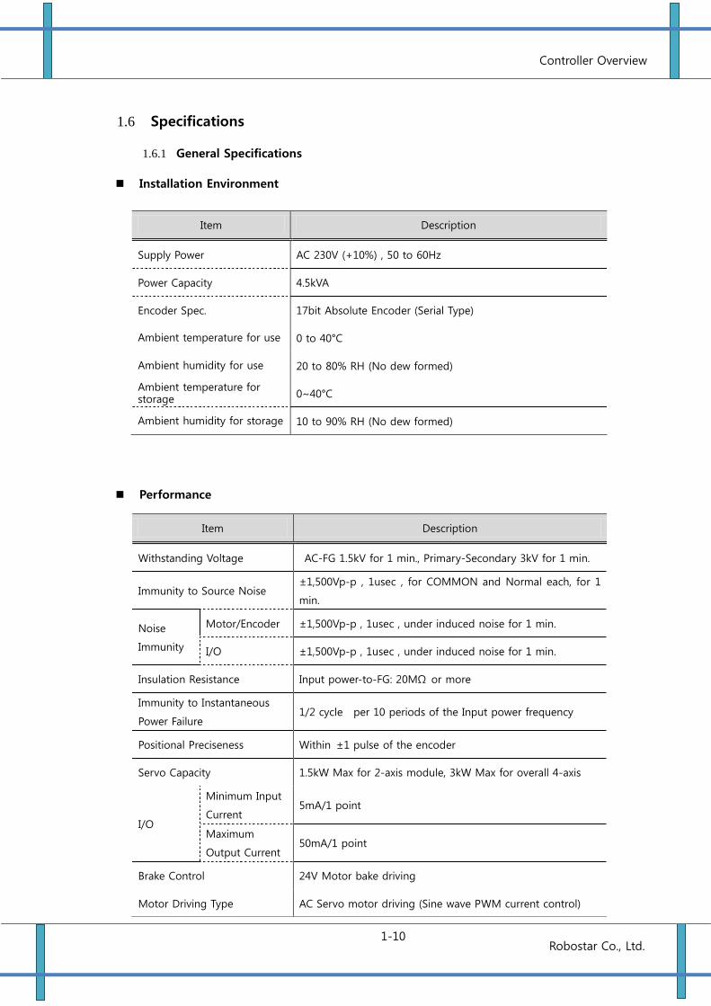
1.6 Specifications
1.6.1 General Specifications
Installation Environment
Performance
Item Description
Supply Power AC 230V (+10%) , 50 to 60Hz
Power Capacity 4.5kVA
Encoder Spec. 17bit Absolute Encoder (Serial Type)
Ambient temperature for use 0 to 40°C
Ambient humidity for use 20 to 80% RH (No dew formed)
Ambient temperature for storage 0~40°C
Ambient humidity for storage 10 to 90% RH (No dew formed)
Item Description
Withstanding Voltage AC-FG 1.5kV for 1 min., Primary-Secondary 3kV for 1 min.
Immunity to Source Noise ±1,500Vp-p , 1usec , for COMMON and Normal each, for 1
min.
Noise
Immunity
Motor/Encoder ±1,500Vp-p , 1usec , under induced noise for 1 min.
I/O ±1,500Vp-p , 1usec , under induced noise for 1 min.
Insulation Resistance Input power-to-FG: 20MΩ or more
Immunity to Instantaneous
Power Failure 1/2 cycle per 10 periods of the Input power frequency
Positional Preciseness Within ±1 pulse of the encoder
Servo Capacity 1.5kW Max for 2-axis module, 3kW Max for overall 4-axis
I/O
Minimum Input
Current 5mA/1 point
Maximum
Output Current 50mA/1 point
Brake Control 24V Motor bake driving
Motor Driving Type AC Servo motor driving (Sine wave PWM current control)
Controller Overview
1-11 Robostar Co., Ltd.
Specifications
Item Function
Robot Control SCARA , Cartesian , Transfer Robot
Behavior Control Type PTP , CP
Control Axis Construction 6 axes
Servo Drive System All-axis, Full-digital AC Servo
Input-Output
(I/O)
SYSTEM System I/O (24 points/12 points)
USER User I/O (16 points/16 points)
Option Option I/O (32 points/32 points)
Teaching Type Direct Teaching (Teach Pendant)
On-Line Teaching (Uni-Host)
Multi Robot Support 2 channels
Robot Language RRL (ROBOSTAR Robot Language)
Robot
Program
Support
Standard
Job Maximum 200 pieces
Point Maximum 2000 pcs per job (Local) , Maximum 1000 pcs per job
(Global)
Step Maximum 2000 Lines
Global
Parameters
Integer type, Maximum 500 pcs , Real number type Maximum 500
pcs
External Communication (option) CC Link , DeviceNet , Profibus , Analog BOARD
Error Indications Front 7-Segment , Teach Pendant
On-Line Functions Job , Point , Parameter UP/Down, and Editing and Storage
Protection Functions IPM Error , Over Current , Over Load , Over Speed, Positional Error,
etc.
Special Functions 3D Palletizing, In-Out Parallel Processing, Real-time Velocity
Control
Cooling Type Forceful Blowing
Dimension 535.8 (W) x 182.8 (D) x 245.0 (H)
Weight 15kg
Ref. 1) The multi-robot support is applied only for a robot model having 3 axes or less.
(See Reference 1)
Controller Overview
1-12 Robostar Co., Ltd.
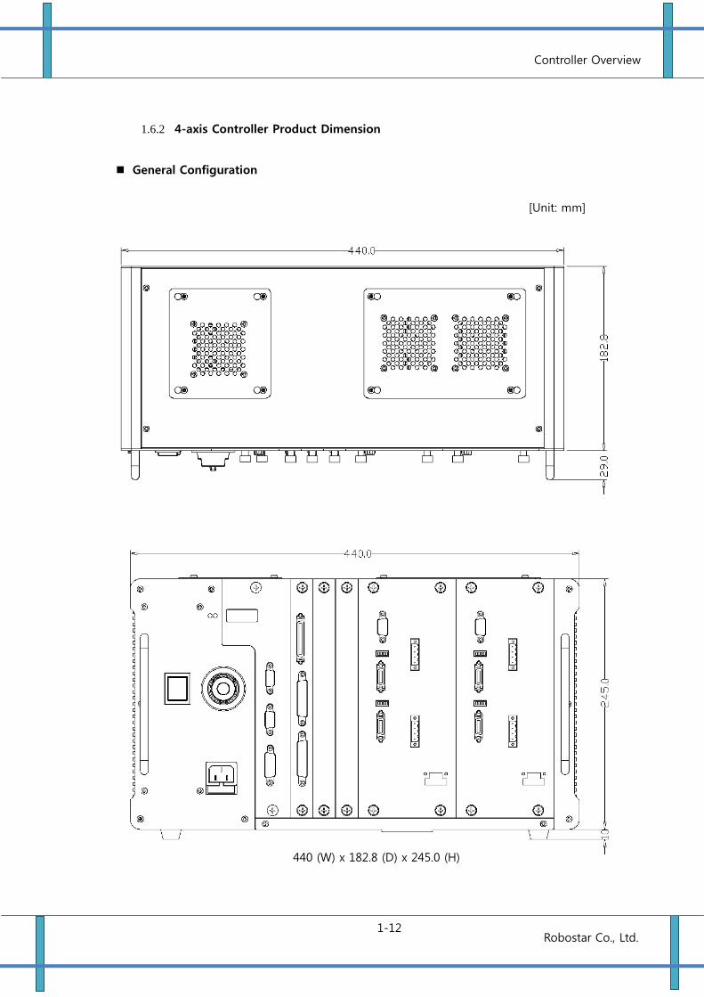
1.6.2 4-axis Controller Product Dimension
General Configuration
440 (W) x 182.8 (D) x 245.0 (H)
[Unit: mm]
Controller Overview
1-13 Robostar Co., Ltd.
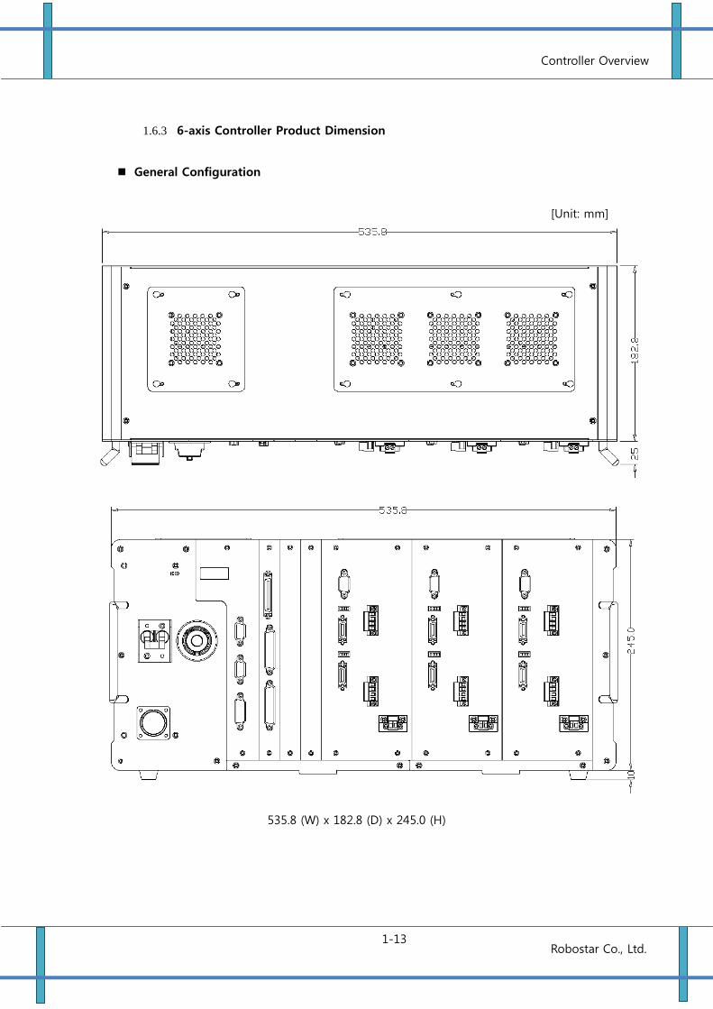
1.6.3 6-axis Controller Product Dimension
General Configuration
[Unit: mm]
535.8 (W) x 182.8 (D) x 245.0 (H)
Controller Overview
1-14 Robostar Co., Ltd.
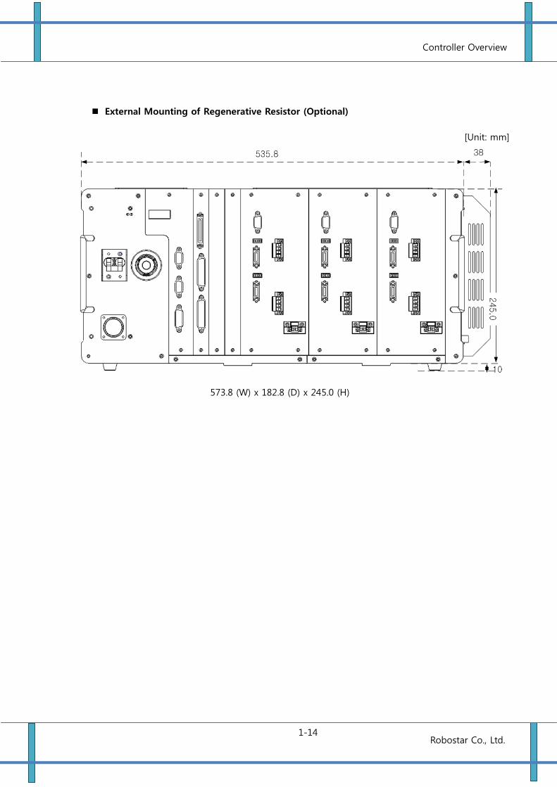
External Mounting of Regenerative Resistor (Optional)
[Unit: mm]
573.8 (W) x 182.8 (D) x 245.0 (H)
Installing Method of Controller
2-1 Robostar Co., Ltd.
Chapter 2 Installing Method of Controller
2.1 Getting Proper Installation Environment
2.1.1 Conditions for Installation Environment
Since the robot and the controller are not intended to be of anti-explosion, dust-proof,
or drop-proof standard, they cannot be installed at the following places.
(1) Environment where flammable gases, flammable liquids, etc. is used
(2) Environment where conductive materials such as metal processed chip is scattering
(3) Environments with acid or alkali corrosive gas
(4) Environments with the mist such as cutting liquid or grinding liquid
(5) Environments with the mist such as cutting liquid or grinding liquid containing the oil
component
(6) Environment close to the electrical noise sources, such as a large inverter, high-power
frequency oscillator, a large conductor, welding machine, etc.
2.1.2 Ambient Temperature and Humidity
Ambient temperature range in operation is to be 0 to 40 .
Be the humidity 80% RH (MAX) or less.
Make well-ventilated and be less dust, dirt and moisture.
2.1.3 Vibration
Install the robot at the place where is away from the environment subjected to
excessive vibration and shock
The installation environment for a robot body and a controller unit is very important. Be sure to
observe the following installation environment. If the installation environment is not proper, the
function and performance may not be fully accomplished, as well as the life of the device may be
shortened and unexpected failures may be caused.
CAUTION
Installing Method of Controller
2-2 Robostar Co., Ltd.
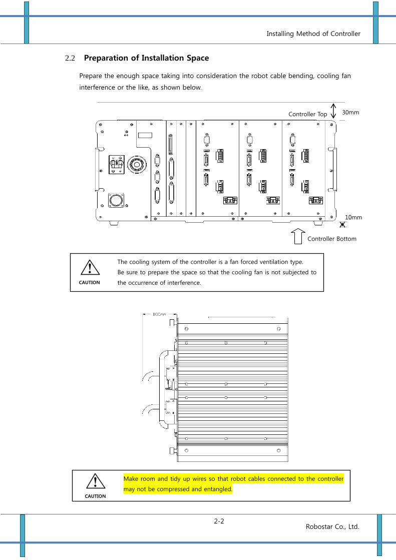
2.2 Preparation of Installation Space
Prepare the enough space taking into consideration the robot cable bending, cooling fan
interference or the like, as shown below.
The cooling system of the controller is a fan forced ventilation type.
Be sure to prepare the space so that the cooling fan is not subjected to
the occurrence of interference.
CAUTION
Make room and tidy up wires so that robot cables connected to the controller
may not be compressed and entangled. CAUTION
Controller Top
Controller Bottom
10mm
30mm
Installing Method of Controller
2-3 Robostar Co., Ltd.
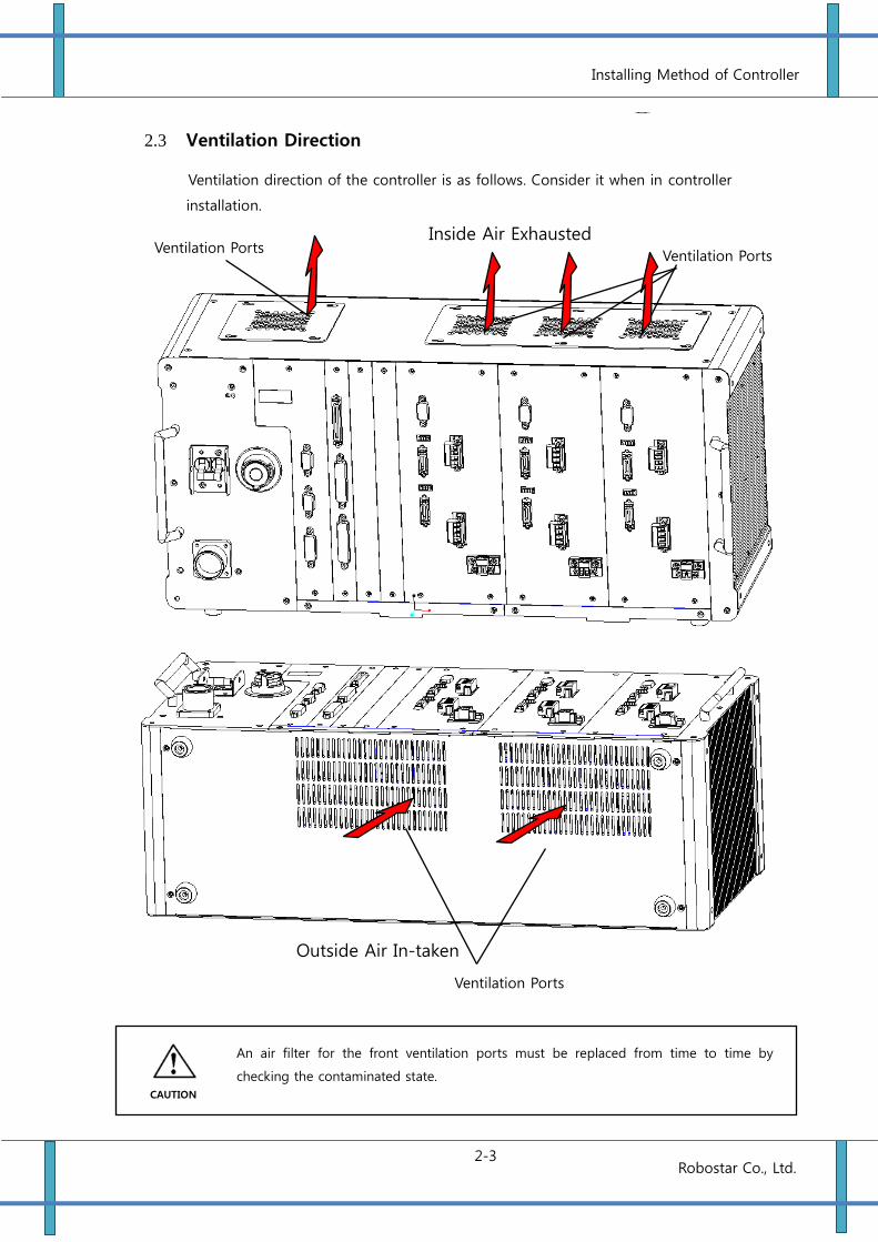
2.3 Ventilation Direction
Ventilation direction of the controller is as follows. Consider it when in controller
installation.
Ventilation Ports
Ventilation Ports
Outside Air In-taken
Inside Air Exhausted
An air filter for the front ventilation ports must be replaced from time to time by
checking the contaminated state.
Ventilation Ports
CAUTION
Robot Connection Method & External Interface
1 - 3-1
Robostar Co., Ltd
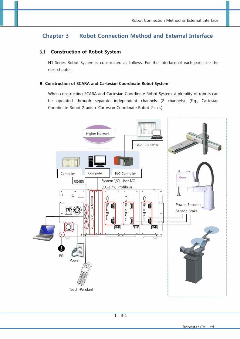
Chapter 3 Robot Connection Method and External Interface
3.1 Construction of Robot System
N1-Series Robot System is constructed as follows. For the interface of each part, see the
next chapter.
Construction of SCARA and Cartesian Coordinate Robot System
When constructing SCARA and Cartesian Coordinate Robot System, a plurality of robots can
be operated through separate independent channels (2 channels). (E.g., Cartesian
Coordinate Robot 2-axis + Cartesian Coordinate Robot 2-axis)
Computer
Field Bus Setter
Controller PLC Controller
Teach-Pendant
FG
Power
Higher Network
System I/O, User I/O
(CC-Link, Profibus)
RS485
Power, Encoder,
Sensor, Brake
Robot Connection Method & External Interface
1 - 3-2
Robostar Co., Ltd
In case the connector of the power cable to robot is wrongly connected, a circuit breaker
shuts off or thethe inside of the controller may be damaged.
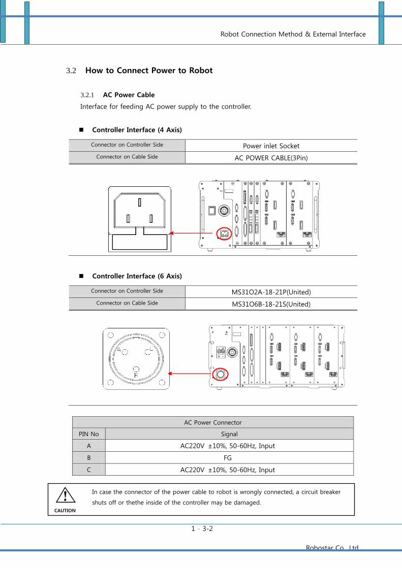
3.2 How to Connect Power to Robot
3.2.1 AC Power Cable
Interface for feeding AC power supply to the controller.
Controller Interface (4 Axis)
Connector on Controller Side Power inlet Socket
Connector on Cable Side AC POWER CABLE(3Pin)
Controller Interface (6 Axis)
Connector on Controller Side MS31O2A-18-21P(United)
Connector on Cable Side MS31O6B-18-21S(United)
AC Power Connector
PIN No Signal
A AC220V ±10%, 50-60Hz, Input
B FG
C AC220V ±10%, 50-60Hz, Input
CAUTION
Robot Connection Method & External Interface
1 - 3-3
Robostar Co., Ltd
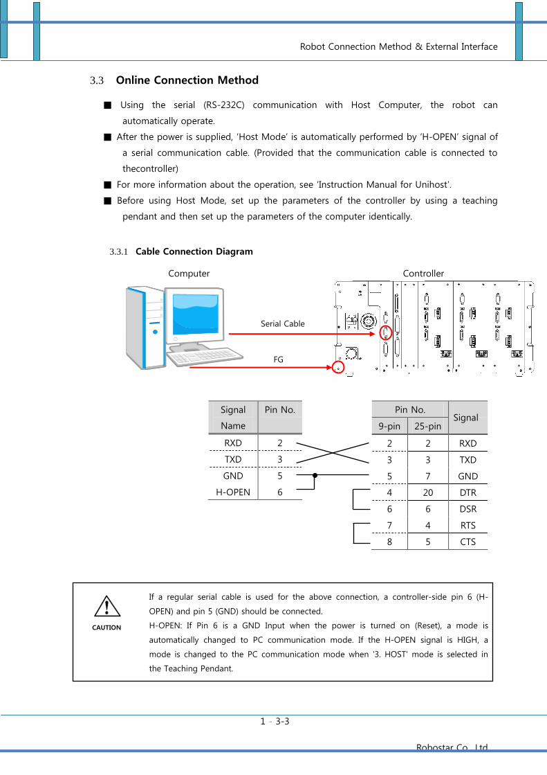
3.3 Online Connection Method
Using the serial (RS-232C) communication with Host Computer, the robot can
automatically operate.
After the power is supplied, ‘Host Mode’ is automatically performed by ‘H-OPEN’ signal of
a serial communication cable. (Provided that the communication cable is connected to
thecontroller)
For more information about the operation, see ‘Instruction Manual for Unihost’.
Before using Host Mode, set up the parameters of the controller by using a teaching
pendant and then set up the parameters of the computer identically.
3.3.1 Cable Connection Diagram
If a regular serial cable is used for the above connection, a controller-side pin 6 (H-
OPEN) and pin 5 (GND) should be connected.
H-OPEN: If Pin 6 is a GND Input when the power is turned on (Reset), a mode is
automatically changed to PC communication mode. If the H-OPEN signal is HIGH, a
mode is changed to the PC communication mode when '3. HOST' mode is selected in
the Teaching Pendant.
Controller Computer
Serial Cable
Connection
FG
Connectio
n
CAUTION
Signal
Name
Pin No.
RXD 2
TXD 3
GND 5
H-OPEN 6
Pin No.
9-pin 25-pin
2 2 RXD
3 3 TXD
5 7 GND
4 20 DTR
6 6 DSR
7 4 RTS
8 5 CTS
Signal
Name
Robot Connection Method & External Interface
1 - 3-4
Robostar Co., Ltd
3.3.2 Specifications for Cable
Use a cable with a shield whose minimum core wire diameter is 0.3mm2 or more.
Connect both lateral shields (Controller and Computer) of a case with each other.
Have FG(Frame Ground) Level of the Controller be the same as that of the Host
Computer. (Using a wire 2 mm2 or more, connect the FG terminal of the controller
with the FG terminal of the host computer.
Use a serial cable not longer than 10m.
Connector Spec.: D-Sub 9s (Socket Type)
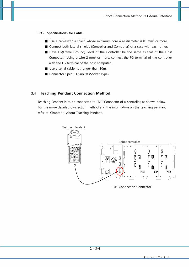
3.4 Teaching Pendant Connection Method
Teaching Pendant is to be connected to ‘T/P’ Connector of a controller, as shown below.
For the more detailed connection method and the information on the teaching pendant,
refer to ‘Chapter 4. About Teaching Pendant’.
Teaching Pendant
Robot controller
‘T/P’ Connection Connector
Robot Connection Method & External Interface
1 - 3-5
Robostar Co., Ltd
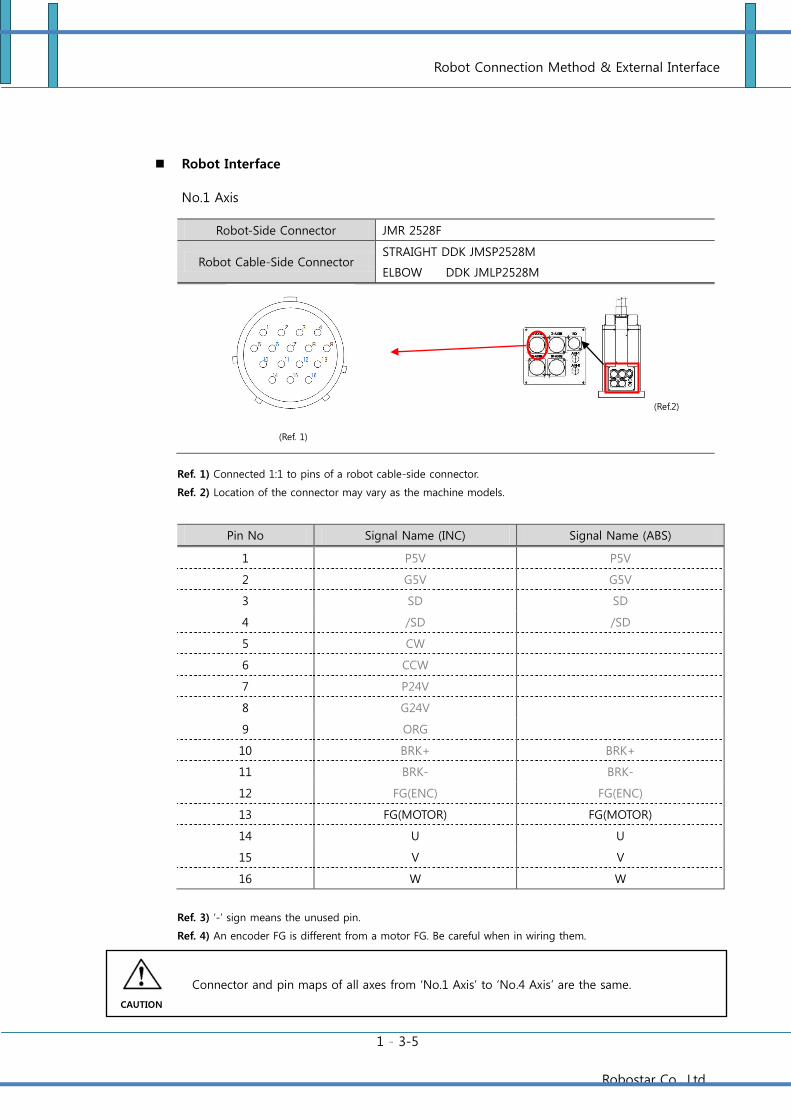
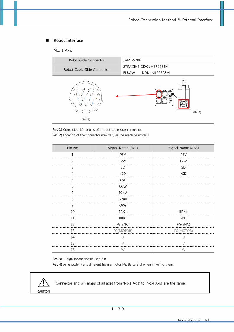
Robot Interface
No.1 Axis
Robot-Side Connector JMR 2528F
Robot Cable-Side Connector STRAIGHT DDK JMSP2528M
ELBOW DDK JMLP2528M
Ref. 1) Connected 1:1 to pins of a robot cable-side connector.
Ref. 2) Location of the connector may vary as the machine models.
Pin No Signal Name (INC) Signal Name (ABS)
1 P5V P5V
2 G5V G5V
3 SD SD
4 /SD /SD
5 CW
6 CCW
7 P24V
8 G24V
9 ORG
10 BRK+ BRK+
11 BRK- BRK-
12 FG(ENC) FG(ENC)
13 FG(MOTOR) FG(MOTOR)
14 U U
15 V V
16 W W
Ref. 3) ‘-‘ sign means the unused pin.
Ref. 4) An encoder FG is different from a motor FG. Be careful when in wiring them.
(Ref. 1)
(Ref.2)
Connector and pin maps of all axes from ‘No.1 Axis’ to ‘No.4 Axis’ are the same.
CAUTION
Robot Connection Method & External Interface
1 - 3-6
Robostar Co., Ltd
After connecting the robot cable, make sure that housing locks (a connector locking device)
of the controller-side connector are completely engaged with each other.
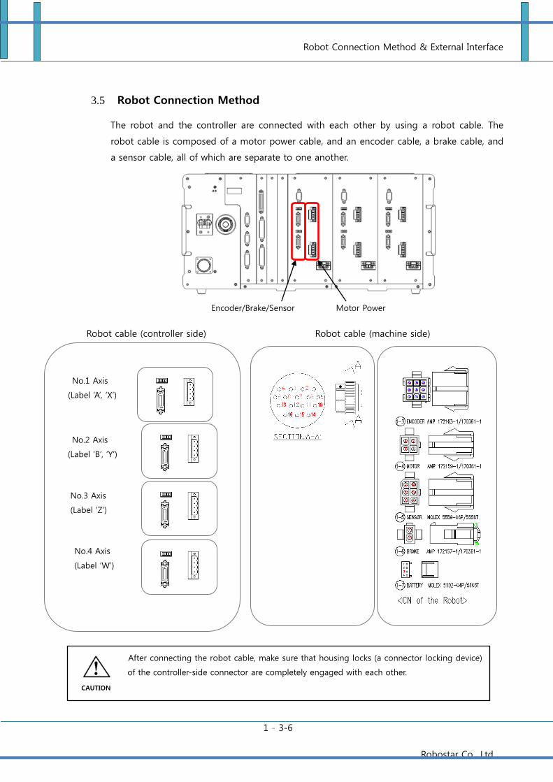
3.5 Robot Connection Method
The robot and the controller are connected with each other by using a robot cable. The
robot cable is composed of a motor power cable, and an encoder cable, a brake cable, and
a sensor cable, all of which are separate to one another.
Robot cable (controller side)
Motor Power Encoder/Brake/Sensor
Robot cable (machine side)
No.1 Axis
(Label ’A’, ‘X’)
No.2 Axis
(Label ’B’, ‘Y’)
No.3 Axis
(Label ’Z’)
No.4 Axis
(Label ’W’)
CAUTION
Robot Connection Method & External Interface
1 - 3-7
Robostar Co., Ltd
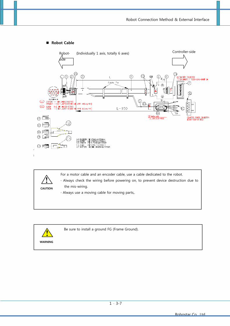
Robot Cable
For a motor cable and an encoder cable, use a cable dedicated to the robot.
∙ Always check the wiring before powering on, to prevent device destruction due to
the mis-wiring.
∙ Always use a moving cable for moving parts,.
Be sure to install a ground FG (Frame Ground).
CAUTION
WARNING
Controller-side Robot-
side
(Individually 1 axis, totally 6 axes)
Robot Connection Method & External Interface
1 - 3-8
Robostar Co., Ltd
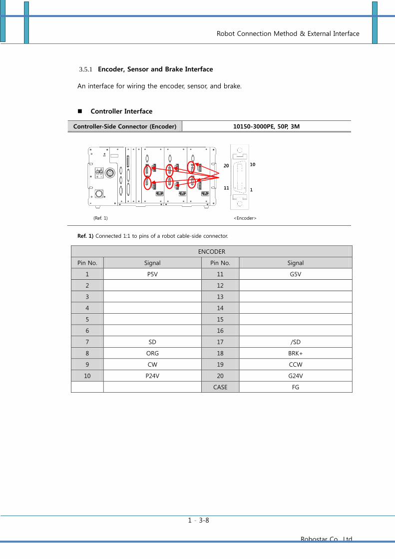
3.5.1 Encoder, Sensor and Brake Interface
An interface for wiring the encoder, sensor, and brake.
Controller Interface
Controller-Side Connector (Encoder) 10150-3000PE, 50P, 3M
Ref. 1) Connected 1:1 to pins of a robot cable-side connector.
ENCODER
Pin No. Signal Pin No. Signal
1 P5V 11 G5V
2 12
3 13
4 14
5 15
6 16
7 SD 17 /SD
8 ORG 18 BRK+
9 CW 19 CCW
10 P24V 20 G24V
CASE FG
(Ref. 1)
<Encoder>
Robot Connection Method & External Interface
1 - 3-9
Robostar Co., Ltd
Robot Interface
No. 1 Axis
Robot-Side Connector JMR 2528F
Robot Cable-Side Connector STRAIGHT DDK JMSP2528M
ELBOW DDK JMLP2528M
Ref. 1) Connected 1:1 to pins of a robot cable-side connector.
Ref. 2) Location of the connector may vary as the machine models.
Pin No Signal Name (INC) Signal Name (ABS)
1 P5V P5V
2 G5V G5V
3 SD SD
4 /SD /SD
5 CW
6 CCW
7 P24V
8 G24V
9 ORG
10 BRK+ BRK+
11 BRK- BRK-
12 FG(ENC) FG(ENC)
13 FG(MOTOR) FG(MOTOR)
14 U U
15 V V
16 W W
Ref. 3) ‘-‘ sign means the unused pin.
Ref. 4) An encoder FG is different from a motor FG. Be careful when in wiring them.
(Ref. 1)
(Ref.2)
Connector and pin maps of all axes from ‘No.1 Axis’ to ‘No.4 Axis’ are the same.
CAUTION
Robot Connection Method & External Interface
1 - 3-10
Robostar Co., Ltd
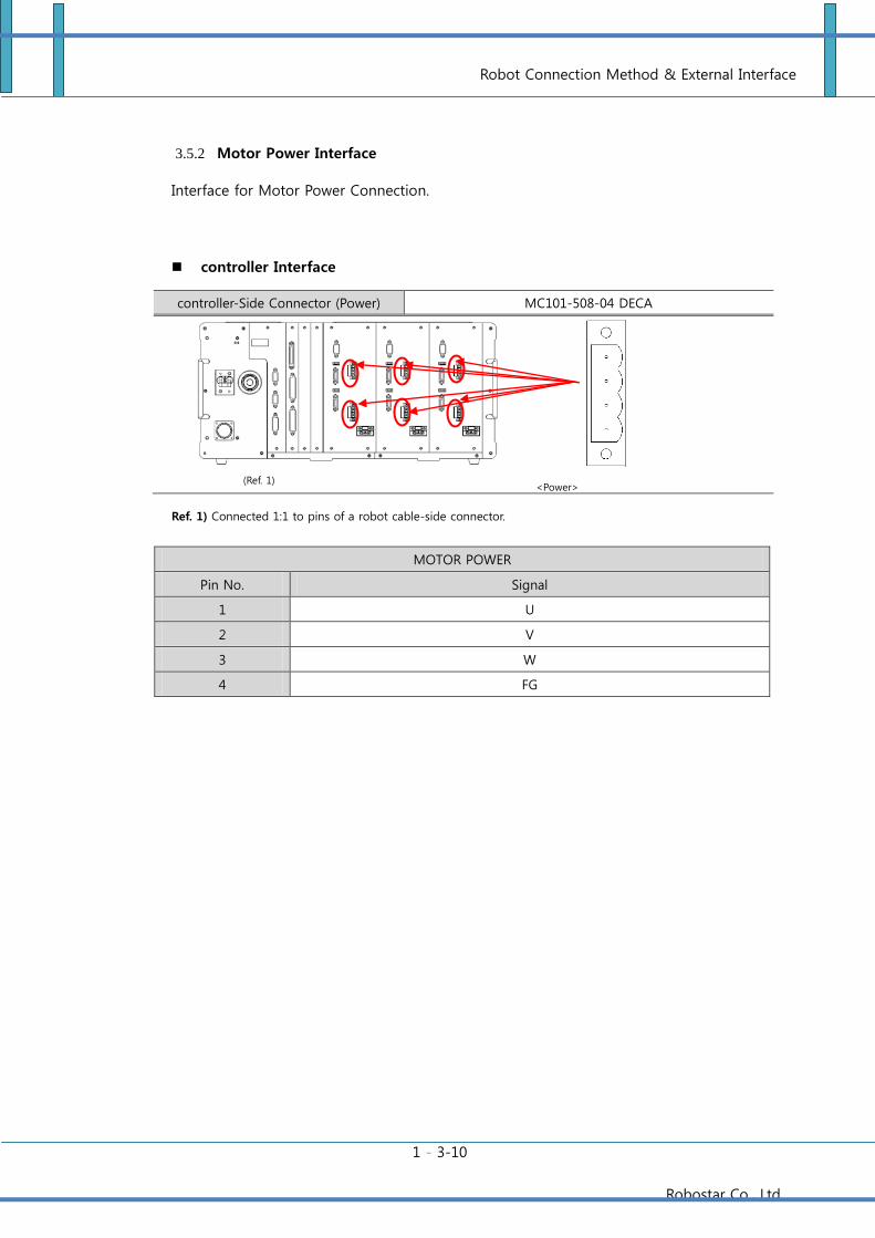
3.5.2 Motor Power Interface
Interface for Motor Power Connection.
controller Interface
controller-Side Connector (Power) MC101-508-04 DECA
Ref. 1) Connected 1:1 to pins of a robot cable-side connector.
MOTOR POWER
Pin No. Signal
1 U
2 V
3 W
4 FG
(Ref. 1)
<Power>
Robot Connection Method & External Interface
1 - 3-11
Robostar Co., Ltd
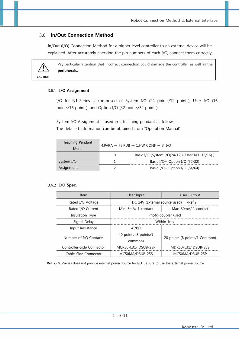
3.6 In/Out Connection Method
In/Out (I/O) Connection Method for a higher level controller to an external device will be
explained. After accurately checking the pin numbers of each I/O, connect them correctly.
3.6.1 I/O Assignment
I/O for N1-Series is composed of System I/O (24 points/12 points), User I/O (16
points/16 points), and Option I/O (32 points/32 points).
System I/O Assignment is used in a teaching pendant as follows.
The detailed information can be obtained from “Operation Manual”.
Teaching Pendant
Menu 4.PARA → F3.PUB → 1.HW CONF → 3. I/O
System I/O
Assignment
0 Basic I/O (System I/O(24/12)+ User I/O (16/16) )
1 Basic I/O+ Option I/O (32/32)
2 Basic I/O+ Option I/O (64/64)
3.6.2 I/O Spec.
Item User Input User Output
Rated I/O Voltage DC 24V (External source used) (Ref.2)
Rated I/O Current Min. 5mA/ 1 contact Max. 30mA/ 1 contact
Insulation Type Photo-coupler used
Signal Delay Within 1ms
Input Resistance 4.7kΩ -
Number of I/O Contacts 40 points (8 points/1
common) 28 points (8 points/1 Common)
Controller-Side Connector MCR50FL31/ DSUB-25P MDR50FL31/ DSUB-25S
Cable-Side Connector MC50MA/DSUB-25S MC50MA/DSUB-25P
Ref. 2) N1-Series does not provide internal power source for I/O. Be sure to use the external power source.
Pay particular attention that incorrect connection could damage the controller, as well as the
peripherals.
CAUTION
Robot Connection Method & External Interface
1 - 3-12
Robostar Co., Ltd
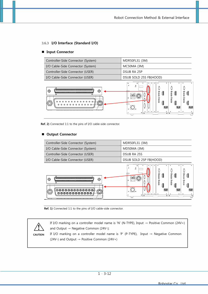
3.6.3 I/O Interface (Standard I/O)
Input Connector
Controller-Side Connector (System) MDR50FL31 (3M)
I/O Cable-Side Connector (System) MC50MA (3M)
Controller-Side Connector (USER) DSUB RA 25P
I/O Cable-Side Connector (USER) DSUB SOLD 25S FB(HOOD)
Ref. 2) Connected 1:1 to the pins of I/O cable-side connector.
Output Connector
Controller-Side Connector (System) MDR50FL31 (3M)
I/O Cable-Side Connector (System) MD50MA (3M)
Controller-Side Connector (USER) DSUB RA 25S
I/O Cable-Side Connector (USER) DSUB SOLD 25P FB(HOOD)
Ref. 1) Connected 1:1 to the pins of I/O cable-side connector.
If I/O marking on a controller model name is ‘N’ (N-TYPE), Input → Positive Common (24V+)
and Output → Negative Common (24V-);
If I/O marking on a controller model name is ‘P’ (P-TYPE), Input → Negative Common
(24V-) and Output → Positive Common (24V+)
(Ref.2)
CAUTION
Robot Connection Method & External Interface
1 - 3-13
Robostar Co., Ltd
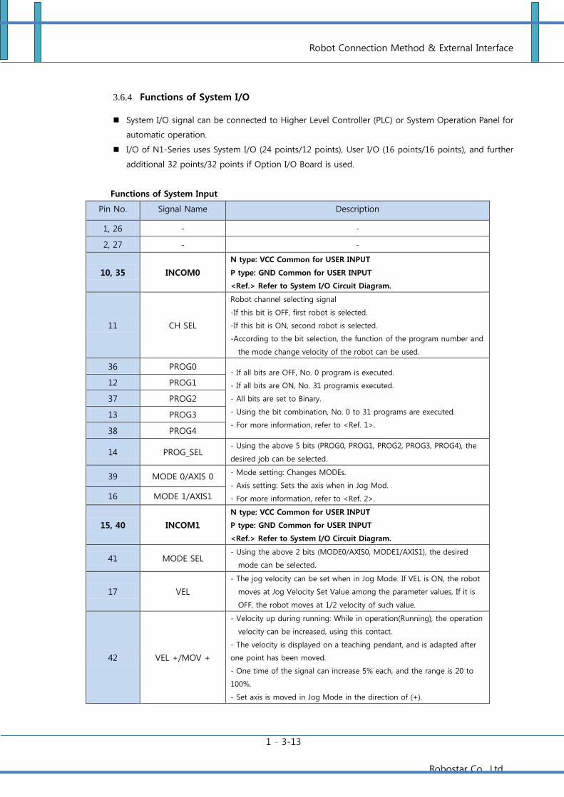
3.6.4 Functions of System I/O
System I/O signal can be connected to Higher Level Controller (PLC) or System Operation Panel for
automatic operation.
I/O of N1-Series uses System I/O (24 points/12 points), User I/O (16 points/16 points), and further
additional 32 points/32 points if Option I/O Board is used.
Functions of System Input
Pin No. Signal Name Description
1, 26 - -
2, 27 - -
10, 35 INCOM0
N type: VCC Common for USER INPUT
P type: GND Common for USER INPUT
<Ref.> Refer to System I/O Circuit Diagram.
11 CH SEL
Robot channel selecting signal
-If this bit is OFF, first robot is selected.
-If this bit is ON, second robot is selected.
-According to the bit selection, the function of the program number and
the mode change velocity of the robot can be used.
36 PROG0 - If all bits are OFF, No. 0 program is executed.
- If all bits are ON, No. 31 programis executed.
- All bits are set to Binary.
- Using the bit combination, No. 0 to 31 programs are executed.
- For more information, refer to <Ref. 1>.
12 PROG1
37 PROG2
13 PROG3
38 PROG4
14 PROG_SEL - Using the above 5 bits (PROG0, PROG1, PROG2, PROG3, PROG4), the
desired job can be selected.
39 MODE 0/AXIS 0 - Mode setting: Changes MODEs.
- Axis setting: Sets the axis when in Jog Mod.
- For more information, refer to <Ref. 2>. 16 MODE 1/AXIS1
15, 40 INCOM1
N type: VCC Common for USER INPUT
P type: GND Common for USER INPUT
<Ref.> Refer to System I/O Circuit Diagram.
41 MODE SEL - Using the above 2 bits (MODE0/AXIS0, MODE1/AXIS1), the desired
mode can be selected.
17 VEL
- The jog velocity can be set when in Jog Mode. If VEL is ON, the robot
moves at Jog Velocity Set Value among the parameter values, If it is
OFF, the robot moves at 1/2 velocity of such value.
42 VEL +/MOV +
- Velocity up during running: While in operation(Running), the operation
velocity can be increased, using this contact.
- The velocity is displayed on a teaching pendant, and is adapted after
one point has been moved.
- One time of the signal can increase 5% each, and the range is 20 to
100%.
- Set axis is moved in Jog Mode in the direction of (+).
Robot Connection Method & External Interface
1 - 3-14
Robostar Co., Ltd
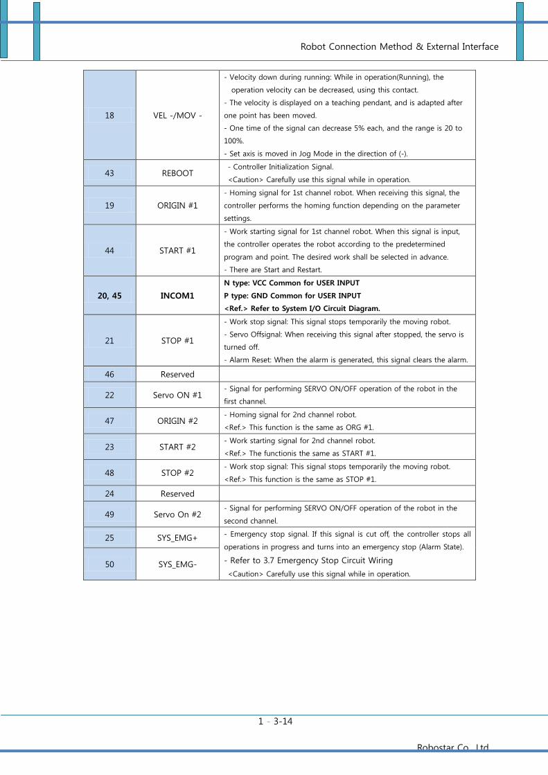
18 VEL -/MOV -
- Velocity down during running: While in operation(Running), the
operation velocity can be decreased, using this contact.
- The velocity is displayed on a teaching pendant, and is adapted after
one point has been moved.
- One time of the signal can decrease 5% each, and the range is 20 to
100%.
- Set axis is moved in Jog Mode in the direction of (-).
43 REBOOT - Controller Initialization Signal.
<Caution> Carefully use this signal while in operation.
19 ORIGIN #1
- Homing signal for 1st channel robot. When receiving this signal, the
controller performs the homing function depending on the parameter
settings.
44 START #1
- Work starting signal for 1st channel robot. When this signal is input,
the controller operates the robot according to the predetermined
program and point. The desired work shall be selected in advance.
- There are Start and Restart.
20, 45 INCOM1
N type: VCC Common for USER INPUT
P type: GND Common for USER INPUT
<Ref.> Refer to System I/O Circuit Diagram.
21 STOP #1
- Work stop signal: This signal stops temporarily the moving robot.
- Servo Offsignal: When receiving this signal after stopped, the servo is
turned off.
- Alarm Reset: When the alarm is generated, this signal clears the alarm.
46 Reserved
22 Servo ON #1 - Signal for performing SERVO ON/OFF operation of the robot in the
first channel.
47 ORIGIN #2 - Homing signal for 2nd channel robot.
<Ref.> This function is the same as ORG #1.
23 START #2 - Work starting signal for 2nd channel robot.
<Ref.> The functionis the same as START #1.
48 STOP #2 - Work stop signal: This signal stops temporarily the moving robot.
<Ref.> This function is the same as STOP #1.
24 Reserved
49 Servo On #2 - Signal for performing SERVO ON/OFF operation of the robot in the
second channel.
25 SYS_EMG+ - Emergency stop signal. If this signal is cut off, the controller stops all
operations in progress and turns into an emergency stop (Alarm State).
- Refer to 3.7 Emergency Stop Circuit Wiring
<Caution> Carefully use this signal while in operation.
50 SYS_EMG-
Robot Connection Method & External Interface
1 - 3-15
Robostar Co., Ltd
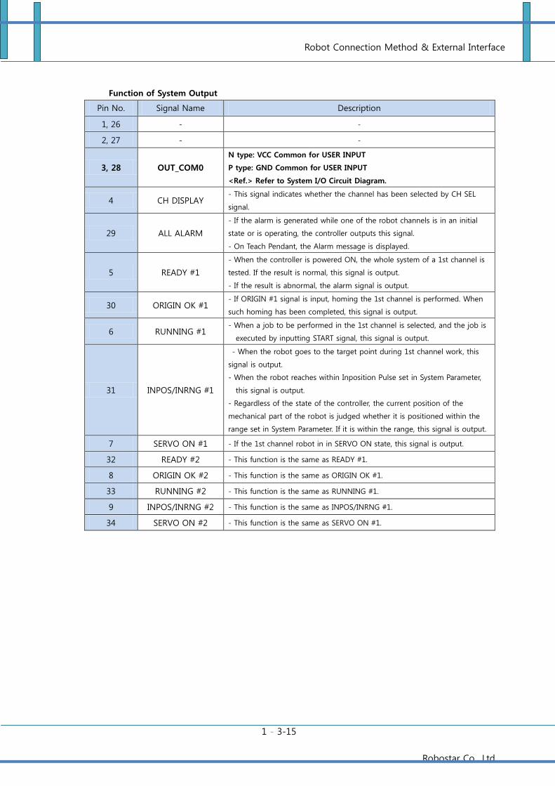
Function of System Output
Pin No. Signal Name Description
1, 26 - -
2, 27 - -
3, 28 OUT_COM0
N type: VCC Common for USER INPUT
P type: GND Common for USER INPUT
<Ref.> Refer to System I/O Circuit Diagram.
4 CH DISPLAY - This signal indicates whether the channel has been selected by CH SEL
signal.
29 ALL ALARM
- If the alarm is generated while one of the robot channels is in an initial
state or is operating, the controller outputs this signal.
- On Teach Pendant, the Alarm message is displayed.
5 READY #1
- When the controller is powered ON, the whole system of a 1st channel is
tested. If the result is normal, this signal is output.
- If the result is abnormal, the alarm signal is output.
30 ORIGIN OK #1 - If ORIGIN #1 signal is input, homing the 1st channel is performed. When
such homing has been completed, this signal is output.
6 RUNNING #1 - When a job to be performed in the 1st channel is selected, and the job is
executed by inputting START signal, this signal is output.
31 INPOS/INRNG #1
- When the robot goes to the target point during 1st channel work, this
signal is output.
- When the robot reaches within Inposition Pulse set in System Parameter,
this signal is output.
- Regardless of the state of the controller, the current position of the
mechanical part of the robot is judged whether it is positioned within the
range set in System Parameter. If it is within the range, this signal is output.
7 SERVO ON #1 - If the 1st channel robot in in SERVO ON state, this signal is output.
32 READY #2 - This function is the same as READY #1.
8 ORIGIN OK #2 - This function is the same as ORIGIN OK #1.
33 RUNNING #2 - This function is the same as RUNNING #1.
9 INPOS/INRNG #2 - This function is the same as INPOS/INRNG #1.
34 SERVO ON #2 - This function is the same as SERVO ON #1.
Robot Connection Method & External Interface
1 - 3-16
Robostar Co., Ltd
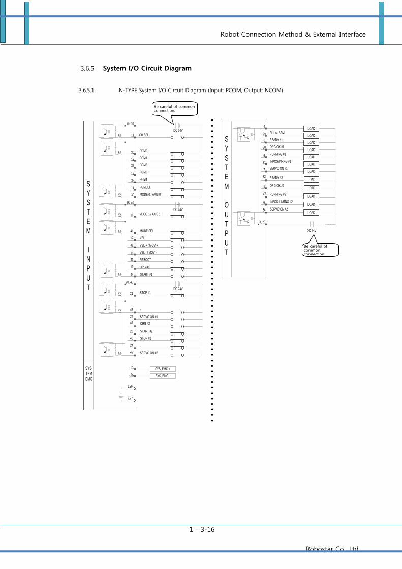
3.6.5 System I/O Circuit Diagram
3.6.5.1 N-TYPE System I/O Circuit Diagram (Input: PCOM, Output: NCOM)
LOAD
LOAD
DC 24V
LOAD
LOAD
LOAD
LOAD
LOAD
LOAD
3, 28
4
29
5
30
6
31
7
32
INPOS/INRNG #1
ALL ALARM
READY #1
ORG OK #1
RUNNING #1
READY #2
ORG OK #2
S
Y
S
T
E
M
O
U
T
P
U
T
SYS_EMG +
SYS_EMG -
SYS-
TEM
EMG
25
50
11
36
12
37
13
38
14
39
DC 24V
10, 35
PGM3
CH SEL
PGM0
PGM1
PGM2
PGM4
PGMSEL
4.7K
4.7K
4.7K
DC 24V
4.7K
4.7K
4.7K
DC 24V
4.7K
4.7K
4.7K
MODE 0 / AXIS 0
VEL - / MOV -
MODE 1 / AXIS 1
MODE SEL
VEL
VEL + / MOV +
REBOOT
ORG #1
16
41
17
42
18
43
19
44
15, 40
START #2
START #1
STOP #1
-
ORG #2
STOP #2
-
21
46
22
47
23
48
24
49
20, 45
S
Y
S
T
E
M
I
N
P
U
T
1,26
2,27
LOAD8
33 RUNNING #2
INPOS / INRNG #2
LOAD
LOAD9
34
LOAD
SERVO ON #1
SERVO ON #2
SERVO ON #1
SERVO ON #2
Be careful of common connection.
Be careful of common connection.
Robot Connection Method & External Interface
1 - 3-17
Robostar Co., Ltd
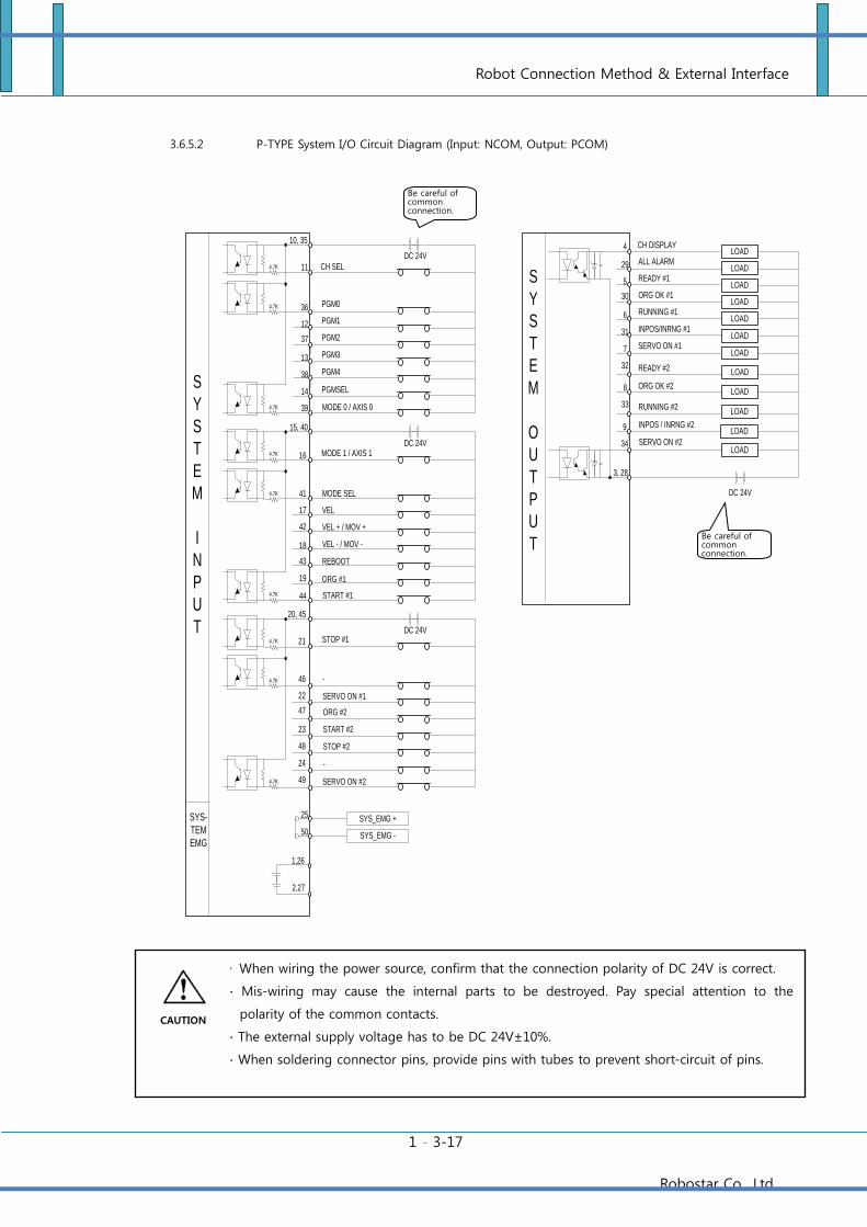
3.6.5.2 P-TYPE System I/O Circuit Diagram (Input: NCOM, Output: PCOM)
LOAD
LOAD
DC 24V
LOAD
LOAD
LOAD
LOAD
LOAD
LOAD
3, 28
4
29
5
30
6
31
7
32
INPOS/INRNG #1
ALL ALARM
READY #1
ORG OK #1
RUNNING #1
READY #2
ORG OK #2
S
Y
S
T
E
M
O
U
T
P
U
T
SYS_EMG +
SYS_EMG -
SYS-
TEM
EMG
25
50
11
36
12
37
13
38
14
39
DC 24V
10, 35
PGM3
CH SEL
PGM0
PGM1
PGM2
PGM4
PGMSEL
4.7K
4.7K
4.7K
DC 24V
4.7K
4.7K
4.7K
DC 24V
4.7K
4.7K
4.7K
MODE 0 / AXIS 0
VEL - / MOV -
MODE 1 / AXIS 1
MODE SEL
VEL
VEL + / MOV +
REBOOT
ORG #1
16
41
17
42
18
43
19
44
15, 40
START #2
START #1
STOP #1
-
ORG #2
STOP #2
-
21
46
22
47
23
48
24
49
20, 45
S
Y
S
T
E
M
I
N
P
U
T
1,26
2,27
LOAD8
33 RUNNING #2
INPOS / INRNG #2
LOAD
LOAD9
34
LOAD
SERVO ON #1
SERVO ON #2
SERVO ON #1
SERVO ON #2
CH DISPLAY
∙ When wiring the power source, confirm that the connection polarity of DC 24V is correct.
∙ Mis-wiring may cause the internal parts to be destroyed. Pay special attention to the
polarity of the common contacts.
∙ The external supply voltage has to be DC 24V±10%.
∙ When soldering connector pins, provide pins with tubes to prevent short-circuit of pins.
Be careful of common connection.
Be careful of common connection.
CAUTION
Robot Connection Method & External Interface
1 - 3-18
Robostar Co., Ltd
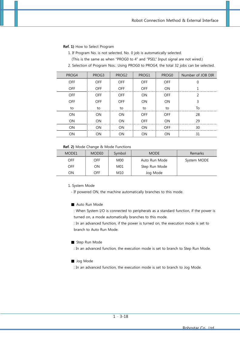
Ref. 1) How to Select Program
1. If Program No. is not selected, No. 0 job is automatically selected.
(This is the same as when “PROG0 to 4” and “PSEL” Input signal are not wired.)
2. Selection of Program Nos.: Using PROG0 to PROG4, the total 32 jobs can be selected.
PROG4 PROG3 PROG2 PROG1 PROG0 Number of JOB DIR
OFF OFF OFF OFF OFF 0
OFF OFF OFF OFF ON 1
OFF OFF OFF ON OFF 2
OFF OFF OFF ON ON 3
to to to to to To
ON ON ON OFF OFF 28
ON ON ON OFF ON 29
ON ON ON ON OFF 30
ON ON ON ON ON 31
Ref. 2) Mode Change & Mode Functions
MODE1 MODE0 Symbol MODE Remarks
OFF OFF M00 Auto Run Mode System MODE
OFF ON M01 Step Run Mode
ON OFF M10 Jog Mode
1. System Mode
- If powered ON, the machine automatically branches to this mode.
Auto Run Mode
: When System I/O is connected to peripherals as a standard function, if the power is
turned on, a mode automatically branches to this mode.
: In an advanced function, if the power is turned on, the execution mode is set to
branch to Auto Run Mode.
Step Run Mode
: In an advanced function, the execution mode is set to branch to Step Run Mode.
Jog Mode
: In an advanced function, the execution mode is set to branch to Jog Mode.
Robot Connection Method & External Interface
1 - 3-19
Robostar Co., Ltd
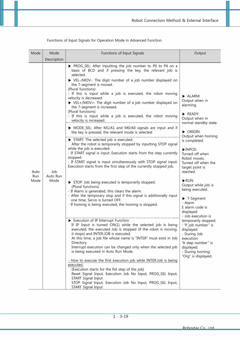
Functions of Input Signals for Operation Mode in Advanced Function
Mode Mode
Description
Functions of Input Signals Output
Auto Run
Mode
Job Auto Run
Mode
PROG_SEL: After inputting the job number to P0 to P4 on a basis of BCD and if pressing the key, the relevant job is selected.
ALARM: Output when in alarming. READY: Output when in normal standby state. ORIGIN: Output when homing is completed. INPOS: Turned off when Robot moves. Turned off when the target point is reached. RUN: Output while job is being executed. 7-Segment: - Alarm E alarm code is displayed - Job execution is temporarily stopped. : “P job number” is displayed. - During Job execution: “A step number” is displayed. - During homing: “Org” is displayed.
VEL-/MOV-: The digit number of a job number displayed on the 7-segment is moved.
(Plural functions) - If this is input while a job is executed, the robot moving velocity is decreased.
VEL+/MOV+: The digit number of a job number displayed on the 7-segment is increased.
(Plural functions) - If this is input while a job is executed, the robot moving
velocity is increased.
MODE_SEL: After M1/A1 and M0/A0 signals are input and if the key is pressed, the relevant mode is selected.
START: The selected job is executed. After the robot is temporarily stopped by inputting STOP signal
while the job is executed: - If START signal is input: Execution starts from the step currently stopped - If START signal is input simultaneously with STOP signal input: Execution starts from the first step of the currently stopped job.
STOP: Job being executed is temporarily stopped. (Plural functions)
- If Alarm is generated, this clears the alarm. - After the temporary stop and if this signal is additionally input
one time, Servo is turned OFF. - If homing is being executed, the homing is stopped.
Execution of IP Interrupt Function If IP Input is turned ON(1) while the selected job is being executed, the executed Job is stopped (if the robot is moving, it stops) and INTER.JOB is executed. At this time, a job file whose name is ”INTER” must exist in Job Directory. Interrupt execution can be changed only when the selected job is being executed in Auto Run Mode.
- How to execute the first execution job while INTER.Job is being executed.
(Execution starts for the fist step of the job) Reset Signal Input, Execution Job No Input, PROG_SEL Input, START Signal Input STOP Signal Input, Execution Job No Input, PROG_SEL Input, START Signal Input
Robot Connection Method & External Interface
1 - 3-20
Robostar Co., Ltd
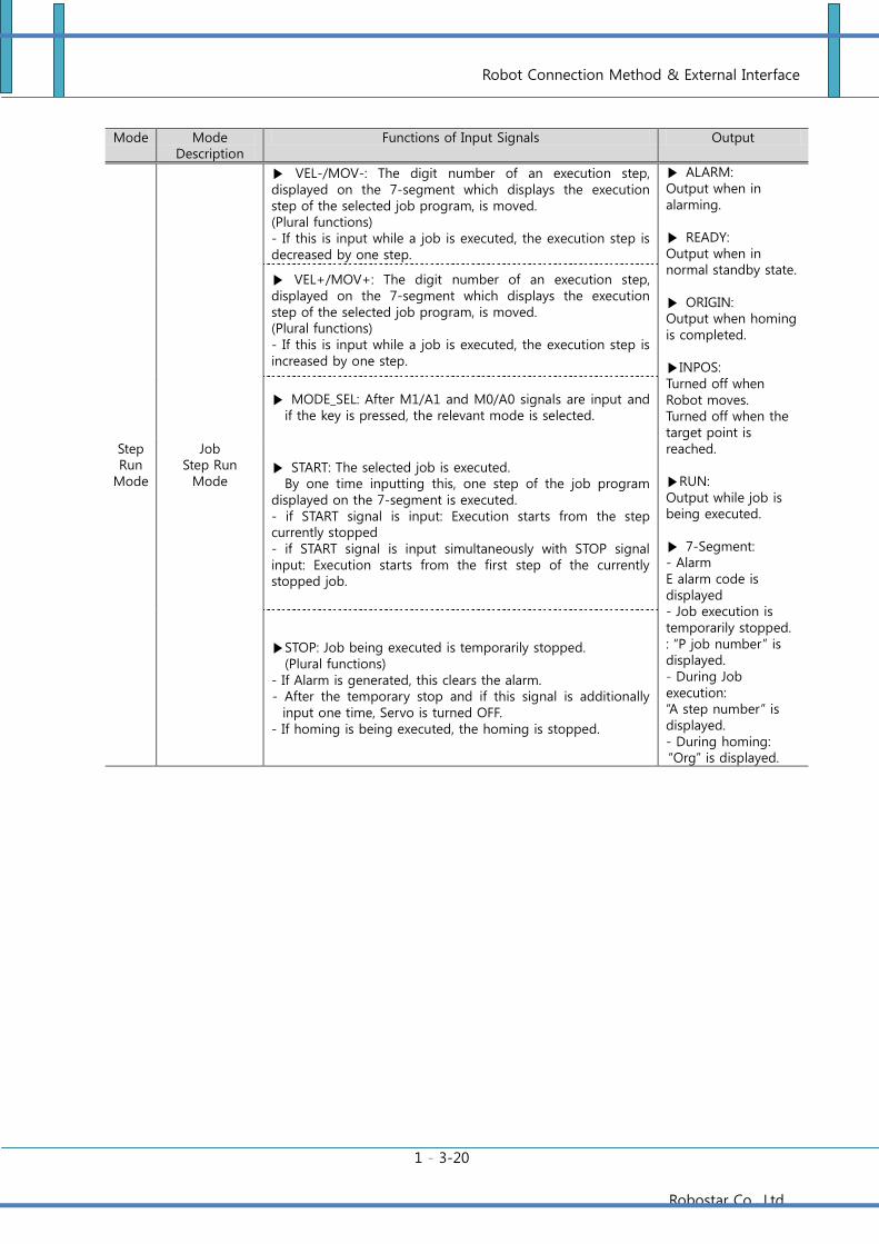
Mode Mode Description
Functions of Input Signals Output
Step Run
Mode
Job Step Run
Mode
VEL-/MOV-: The digit number of an execution step, displayed on the 7-segment which displays the execution step of the selected job program, is moved. (Plural functions) - If this is input while a job is executed, the execution step is decreased by one step.
ALARM: Output when in alarming. READY: Output when in normal standby state. ORIGIN: Output when homing is completed. INPOS: Turned off when Robot moves. Turned off when the target point is reached. RUN: Output while job is being executed. 7-Segment: - Alarm E alarm code is displayed - Job execution is temporarily stopped. : “P job number” is displayed. - During Job execution: “A step number” is displayed. - During homing: “Org” is displayed.
VEL+/MOV+: The digit number of an execution step, displayed on the 7-segment which displays the execution step of the selected job program, is moved. (Plural functions) - If this is input while a job is executed, the execution step is increased by one step.
MODE_SEL: After M1/A1 and M0/A0 signals are input and if the key is pressed, the relevant mode is selected.
START: The selected job is executed. By one time inputting this, one step of the job program
displayed on the 7-segment is executed. - if START signal is input: Execution starts from the step currently stopped - if START signal is input simultaneously with STOP signal input: Execution starts from the first step of the currently stopped job.
STOP: Job being executed is temporarily stopped. (Plural functions)
- If Alarm is generated, this clears the alarm. - After the temporary stop and if this signal is additionally
input one time, Servo is turned OFF. - If homing is being executed, the homing is stopped.
Robot Connection Method & External Interface
1 - 3-21
Robostar Co., Ltd
Mode Mode
Description
Functions of Input Signal Output
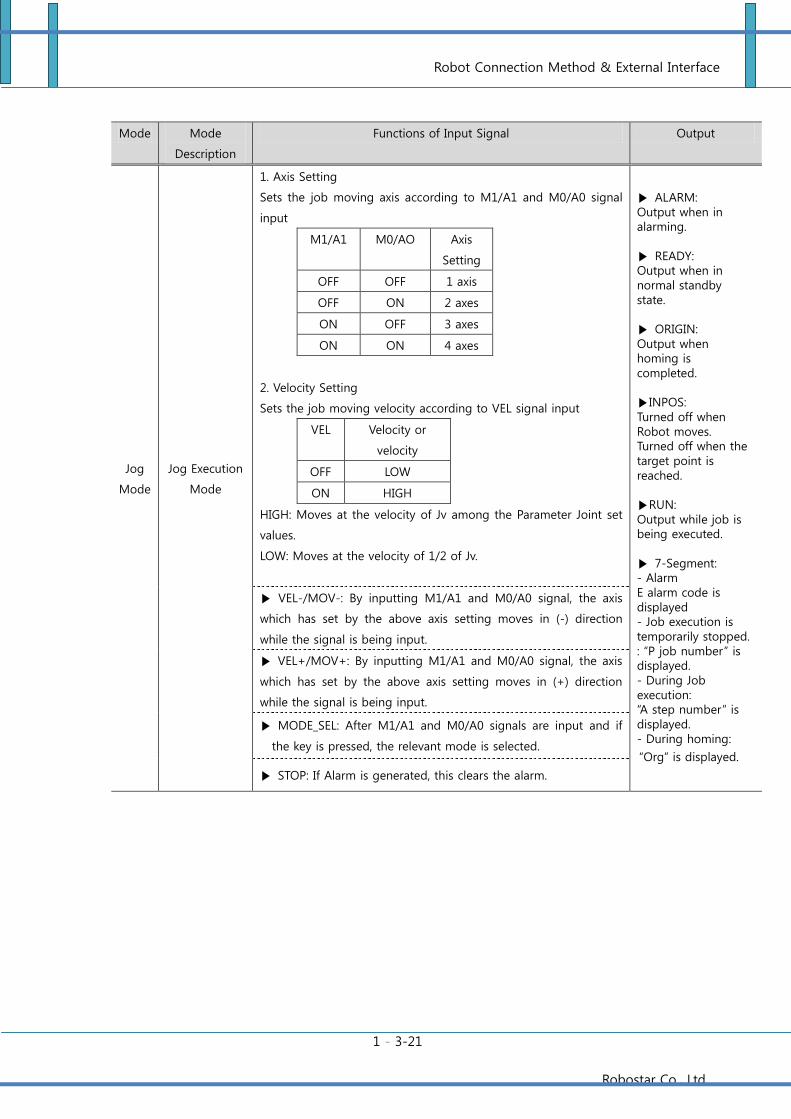
Jog
Mode
Jog Execution
Mode
1. Axis Setting
Sets the job moving axis according to M1/A1 and M0/A0 signal
input
M1/A1 M0/AO Axis
Setting
OFF OFF 1 axis
OFF ON 2 axes
ON OFF 3 axes
ON ON 4 axes
2. Velocity Setting
Sets the job moving velocity according to VEL signal input
VEL Velocity or
velocity
OFF LOW
ON HIGH
HIGH: Moves at the velocity of Jv among the Parameter Joint set
values.
LOW: Moves at the velocity of 1/2 of Jv.
ALARM: Output when in alarming. READY: Output when in normal standby state. ORIGIN: Output when homing is completed. INPOS: Turned off when Robot moves. Turned off when the target point is reached. RUN: Output while job is being executed. 7-Segment: - Alarm E alarm code is displayed - Job execution is temporarily stopped. : “P job number” is displayed. - During Job execution: “A step number” is displayed. - During homing:
“Org” is displayed.
VEL-/MOV-: By inputting M1/A1 and M0/A0 signal, the axis
which has set by the above axis setting moves in (-) direction
while the signal is being input.
VEL+/MOV+: By inputting M1/A1 and M0/A0 signal, the axis
which has set by the above axis setting moves in (+) direction
while the signal is being input.
MODE_SEL: After M1/A1 and M0/A0 signals are input and if
the key is pressed, the relevant mode is selected.
STOP: If Alarm is generated, this clears the alarm.
Robot Connection Method & External Interface
1 - 3-22
Robostar Co., Ltd
3.6.6 Connector Configuration & Circuit Diagram of User I/0
USER Input Function and Pin Map
Pin No. Name Description
1, 14 - -
2, 15 - -
4, 16 IN_COM0
N type: VCC Common for USER INPUT
P type: GND Common for USER INPUT
<Ref.> Refer to System I/O Circuit Diagram.
17 USER IN 0 System/User Input Contact 0
5 USER IN 1 System/User Input Contact 1
18 USER IN 2 System/User Input Contact 2
6 USER IN 3 System/User Input Contact 3
19 USER IN 4 System/User Input Contact 4
7 USER IN 5 System/User Input Contact 5
20 USER IN 6 System/User Input Contact 6
8 USER IN 7 System/User Input Contact 7
9, 21 IN_COM1
N type: VCC Common for USER INPUT
P type: GND Common for USER INPUT
<Ref.> Refer to System I/O Circuit Diagram.
22 USER IN 8 System/User Input Contact 8
10 USER IN 9 System/User Input Contact 9
23 USER IN 10 System/User Input Contact 10
11 USER IN 11 System/User Input Contact 11
24 USER IN 12 System/User Input Contact 12
12 USER IN 13 System/User Input Contact 13
25 USER IN 14 System/User Input Contact 14
13 USER IN 15 System/User Input Contact 15
Ref. 1) ‘-‘ sign means the unused pin.
Robot Connection Method & External Interface
1 - 3-23
Robostar Co., Ltd
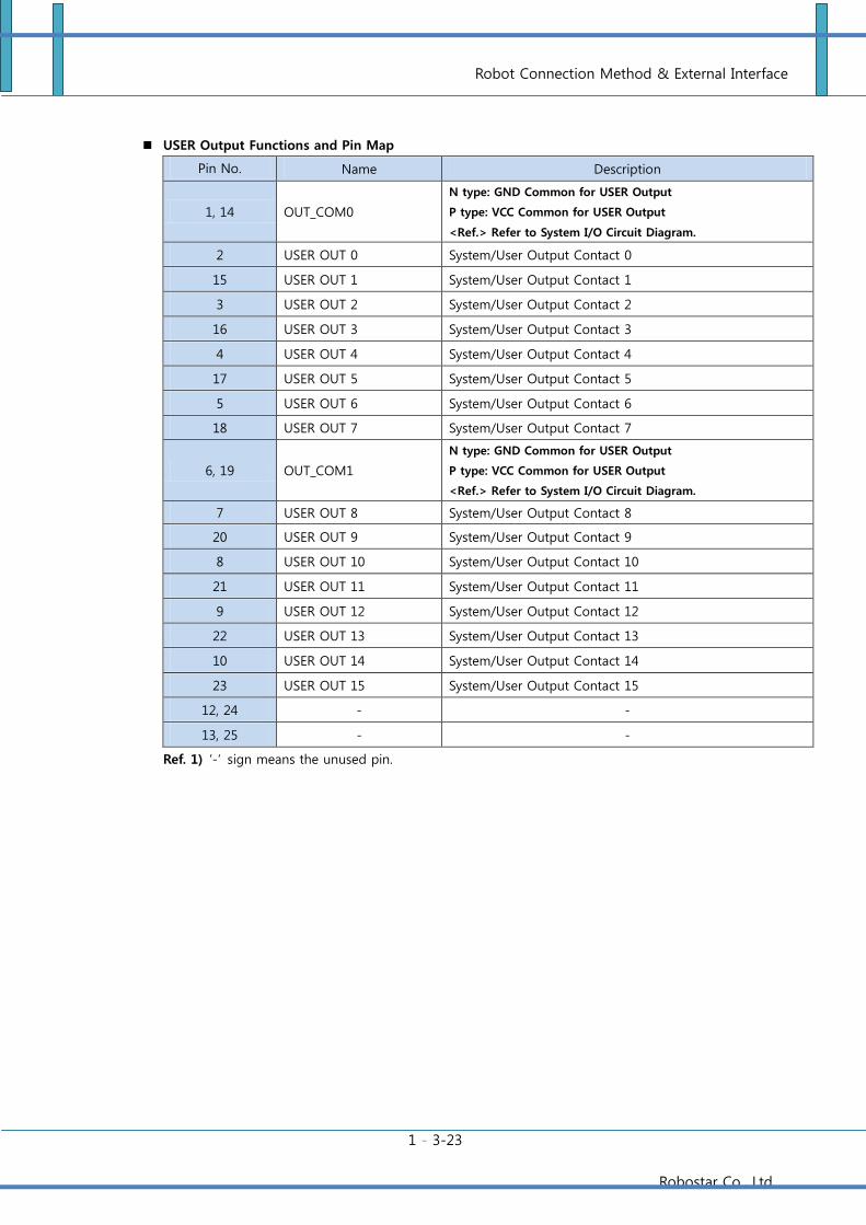
USER Output Functions and Pin Map
Pin No. Name Description
1, 14 OUT_COM0
N type: GND Common for USER Output
P type: VCC Common for USER Output
<Ref.> Refer to System I/O Circuit Diagram.
2 USER OUT 0 System/User Output Contact 0
15 USER OUT 1 System/User Output Contact 1
3 USER OUT 2 System/User Output Contact 2
16 USER OUT 3 System/User Output Contact 3
4 USER OUT 4 System/User Output Contact 4
17 USER OUT 5 System/User Output Contact 5
5 USER OUT 6 System/User Output Contact 6
18 USER OUT 7 System/User Output Contact 7
6, 19 OUT_COM1
N type: GND Common for USER Output
P type: VCC Common for USER Output
<Ref.> Refer to System I/O Circuit Diagram.
7 USER OUT 8 System/User Output Contact 8
20 USER OUT 9 System/User Output Contact 9
8 USER OUT 10 System/User Output Contact 10
21 USER OUT 11 System/User Output Contact 11
9 USER OUT 12 System/User Output Contact 12
22 USER OUT 13 System/User Output Contact 13
10 USER OUT 14 System/User Output Contact 14
23 USER OUT 15 System/User Output Contact 15
12, 24 - -
13, 25 - -
Ref. 1) ‘-‘ sign means the unused pin.
Robot Connection Method & External Interface
1 - 3-24
Robostar Co., Ltd
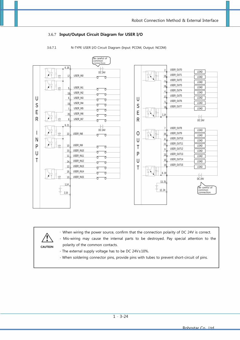
3.6.7 Input/Output Circuit Diagram for USER I/O
3.6.7.1 N-TYPE USER I/O Circuit Diagram (Input: PCOM, Output: NCOM)
LOAD
LOAD
DC 24V
LOAD
LOAD
LOAD
LOAD
LOAD
LOAD
LOAD
LOAD
DC 24V
LOAD
LOAD
LOAD
LOAD
LOAD
LOAD
1,14
2
15
3
16
4
17
5
18
6, 19
7
20
8
21
9
22
10
23
USER_OUT0
USER_OUT5
USER_OUT1
USER_OUT2
USER_OUT3
USER_OUT4
USER_OUT6
USER_OUT7
USER_OUT8
USER_OUT13
USER_OUT9
USER_OUT10
USER_OUT11
USER_OUT12
USER_OUT14
USER_OUT15
17
5
18
6
19
7
20
8
DC 24V
4, 16
USER_IN0
USER_IN5
USER_IN1
USER_IN2
USER_IN3
USER_IN4
USER_IN6
USER_IN7
4.7K
4.7K
4.7K
DC 24V
4.7K
4.7K
4.7K
USER_IN8
USER_IN13
USER_IN9
USER_IN10
USER_IN11
USER_IN12
USER_IN14
USER_IN15
22
10
23
11
24
12
25
13
9, 21
U
S
E
R
I
N
P
U
T
U
S
E
R
O
U
T
P
U
T
1,14
2,15
13, 25
12, 24
Be careful of common connection.
Be careful of common connection.
∙ When wiring the power source, confirm that the connection polarity of DC 24V is correct.
∙ Mis-wiring may cause the internal parts to be destroyed. Pay special attention to the
polarity of the common contacts.
∙ The external supply voltage has to be DC 24V±10%.
∙ When soldering connector pins, provide pins with tubes to prevent short-circuit of pins.
CAUTION
Robot Connection Method & External Interface
1 - 3-25
Robostar Co., Ltd
3.6.7.2 P-TYPE USER I/O Circuit Diagram (Input: NCOM, Output: PCOM)
LOAD
LOAD
DC 24V
LOAD
LOAD
LOAD
LOAD
LOAD
LOAD
LOAD
LOAD
DC 24V
LOAD
LOAD
LOAD
LOAD
LOAD
LOAD
1,14
2
15
3
16
4
17
5
18
6, 19
7
20
8
21
9
22
10
23
USER_OUT0
USER_OUT5
USER_OUT1
USER_OUT2
USER_OUT3
USER_OUT4
USER_OUT6
USER_OUT7
USER_OUT8
USER_OUT13
USER_OUT9
USER_OUT10
USER_OUT11
USER_OUT12
USER_OUT14
USER_OUT15
17
5
18
6
19
7
20
8
DC 24V
4, 16
USER_IN0
USER_IN5
USER_IN1
USER_IN2
USER_IN3
USER_IN4
USER_IN6
USER_IN7
4.7K
4.7K
4.7K
DC 24V
4.7K
4.7K
4.7K
USER_IN8
USER_IN13
USER_IN9
USER_IN10
USER_IN11
USER_IN12
USER_IN14
USER_IN15
22
10
23
11
24
12
25
13
9, 21
U
S
E
R
I
N
P
U
T
U
S
E
R
O
U
T
P
U
T
1,14
2,15
13, 25
12, 24
∙ When wiring the power source, confirm that the connection polarity of DC 24V is correct.
∙ Mis-wiring may cause the internal parts to be destroyed. Pay special attention to the
polarity of the common contacts.
∙ The external supply voltage has to be DC 24V±10%.
∙ When soldering connector pins, provide pins with tubes to prevent short-circuit of pins.
Be careful of common connection.
Be careful of common connection.
CAUTION
Robot Connection Method & External Interface
1 - 3-26
Robostar Co., Ltd
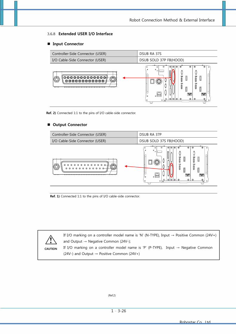
3.6.8 Extended USER I/O Interface
Input Connector
Controller-Side Connector (USER) DSUB RA 37S
I/O Cable-Side Connector (USER) DSUB SOLD 37P FB(HOOD)
Ref. 2) Connected 1:1 to the pins of I/O cable-side connector.
Output Connector
Controller-Side Connector (USER) DSUB RA 37P
I/O Cable-Side Connector (USER) DSUB SOLD 37S FB(HOOD)
Ref. 1) Connected 1:1 to the pins of I/O cable-side connector.
If I/O marking on a controller model name is ‘N’ (N-TYPE), Input → Positive Common (24V+)
and Output → Negative Common (24V-);
If I/O marking on a controller model name is ‘P’ (P-TYPE), Input → Negative Common
(24V-) and Output → Positive Common (24V+)
(Ref.2)
CAUTION
Robot Connection Method & External Interface
1 - 3-27
Robostar Co., Ltd
3.6.9 Extended USER I/O Connector Configuration & Circuit Diagram
Extended USER Input Functions and Pin Map
PIN
NUMBER Classifications Description
PIN
NUMBER Classifications Description
1 FG FG 20 IN_COM1
N type : VCC Common
P type : GND Common
<Ref.>I/O Circuit Diagram Ref.
2 USER IN 16 Extended User Input Contact 16 21 USER IN 17 Extended User Input Contact 17
3 USER IN 18 Extended User Input Contact 18 22 USER IN 19 Extended User Input Contact 19
4 USER IN 20 Extended User Input Contact 20 23 USER IN 21 Extended User Input Contact 21
5 USER IN 22 Extended User Input Contact 22 24 USER IN 23 Extended User Input Contact 23
6 IN_COM2
N type : VCC Common
P type : GND Common
<Ref.>I/O Circuit Diagram Ref.
25 USER IN 24 Extended User Input Contact 24
7 USER IN 25 Extended User Input Contact 25 26 USER IN 26 Extended User Input Contact 26
8 USER IN 27 Extended User Input Contact 27 27 USER IN 28 Extended User Input Contact 28
9 USER IN 29 Extended User Input Contact 29 28 USER IN 30 Extended User Input Contact 30
10 USER IN 31 Extended User Input Contact 31 29 IN_COM3
N type : VCC Common
P type : GND Common
<Ref.>I/O Circuit Diagram Ref.
11 USER IN 32 Extended User Input Contact 32 30 USER IN 33 Extended User Input Contact 33
12 USER IN 34 Extended User Input Contact 34 31 USER IN 35 Extended User Input Contact 35
13 USER IN 36 Extended User Input Contact 36 32 USER IN 37 Extended User Input Contact 37
14 USER IN 38 Extended User Input Contact 38 33 USER IN 39 Extended User Input Contact 39
15 IN_COM4
N type : VCC Common
P type : GND Common
<Ref.>I/O Circuit Diagram Ref.
34 USER IN 40 Extended User Input Contact 40
16 USER IN 41 Extended User Input Contact 41 35 USER IN 42 Extended User Input Contact 42
17 USER IN 43 Extended User Input Contact 43 36 USER IN 44 Extended User Input Contact 44
18 USER IN 45 Extended User Input Contact 45 37 USER IN 46 Extended User Input Contact 46
19 USER IN 47 Extended User Input Contact 47
Ref. 1) ‘-‘ sign means the unused pin.
Robot Connection Method & External Interface
1 - 3-28
Robostar Co., Ltd
Extended USER Output Functions and Pin Map
PIN
NUMB
ER
구분 설명
PIN
NUMB
ER
구분 설명
1 FG FG 20 USER OUT 47 Extended User Output Contact 47
2 USER OUT 46 Extended User Output Contact 46 21 USER OUT 45 Extended User Output Contact 45
3 USER OUT 44 Extended User Output Contact 44 22 USER OUT 43 Extended User Output Contact 43
4 USER OUT 42 Extended User Output Contact 42 23 USER OUT 41 Extended User Output Contact 41
5 USER OUT 40 Extended User Output Contact 40 24 IN_COM3
N type : GND Common
P type : VCC Common
<Ref.> Refer to I/O Circuit Diagram.
6 USER OUT 39 Extended User Output Contact 39 25 USER OUT 38 Extended User Output Contact 38
7 USER OUT 37 Extended User Output Contact 37 26 USER OUT 36 Extended User Output Contact 36
8 USER OUT 35 Extended User Output Contact 35 27 USER OUT 34 Extended User Output Contact 34
9 USER OUT 33 Extended User Output Contact 33 28 USER OUT 32 Extended User Output Contact 32
10 OUT_COM2
N type : GND Common
P type : VCC Common
<Ref.> Refer to I/O Circuit Diagram.
29 USER OUT 31 Extended User Output Contact 31
11 USER OUT 30 Extended User Output Contact 30 30 USER OUT 29 Extended User Output Contact 29
12 USER OUT 28 Extended User Output Contact 28 31 USER OUT 27 Extended User Output Contact 27
13 USER OUT 26 Extended User Output Contact 26 32 USER OUT 25 Extended User Output Contact 25
14 USER OUT 24 Extended User Output Contact 24 33 OUT_COM1
N type : GND Common
P type : VCC Common
<Ref.> Refer to I/O Circuit Diagram.
15 USER OUT 23 Extended User Output Contact 23 34 USER OUT 22 Extended User Output Contact 22
16 USER OUT 21 Extended User Output Contact 21 35 USER OUT 20 Extended User Output Contact 20
17 USER OUT 19 Extended User Output Contact 19 36 USER OUT 18 Extended User Output Contact 18
18 USER OUT 17 Extended User Output Contact 17 37 USER OUT 16 Extended User Output Contact 16
19 OUT_COM0
N type : GND Common
P type : VCC Common
<Ref.> Refer to I/O Circuit Diagram.
Ref. 1) ‘-‘ sign means the unused pin.
Robot Connection Method & External Interface
1 - 3-29
Robostar Co., Ltd
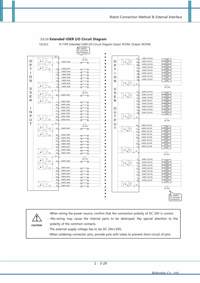
3.6.10 Extended USER I/O Circuit Diagram
3.6.10.1 N-TYPE Extended USER I/O Circuit Diagram (Input: PCOM, Output: NCOM)
LOAD
LOAD
DC 24V
LOAD
LOAD
LOAD
LOAD
LOAD
LOAD
LOAD
LOAD
DC 24V
LOAD
LOAD
LOAD
LOAD
LOAD
LOAD
19
37
18
36
17
35
16
34
15
33
14
32
13
31
12
30
11
29
USER_OUT16
USER_OUT21
USER_OUT17
USER_OUT18
USER_OUT19
USER_OUT20
USER_OUT22
USER_OUT23
USER_OUT24
USER_OUT29
USER_OUT25
USER_OUT26
USER_OUT27
USER_OUT28
USER_OUT30
USER_OUT31
2
21
3
22
5
23
7
24
DC 24V
20
USER_IN16
USER_IN21
USER_IN17
USER_IN18
USER_IN19
USER_IN20
USER_IN22
USER_IN23
4.7K
4.7K
4.7K
DC 24V
4.7K
4.7K
4.7K
USER_IN24
USER_IN29
USER_IN25
USER_IN26
USER_IN27
USER_IN28
USER_IN30
USER_IN31
25
7
26
8
27
9
28
10
6
O
P
T
I
O
N
U
S
E
R
I
N
P
U
T
O
P
T
I
O
N
U
S
E
R
O
U
T
P
U
TDC 24V
4.7K
4.7K
4.7K
USER_IN32
USER_IN37
USER_IN33
USER_IN34
USER_IN35
USER_IN36
USER_IN38
USER_IN39
11
30
12
31
13
32
14
33
29
DC 24V
4.7K
4.7K
4.7K
USER_IN40
USER_IN45
USER_IN41
USER_IN42
USER_IN43
USER_IN44
USER_IN46
USER_IN47
34
16
35
17
36
18
37
19
15
LOAD
LOAD
DC 24V
LOAD
LOAD
LOAD
LOAD
LOAD
LOAD
10
28
9
27
8
26
7
25
6
USER_OUT32
USER_OUT37
USER_OUT33
USER_OUT34
USER_OUT35
USER_OUT36
USER_OUT38
USER_OUT39
LOAD
LOAD
DC 24V
LOAD
LOAD
LOAD
LOAD
LOAD
LOAD
24
5
23
4
22
3
21
2
20
USER_OUT40
USER_OUT45
USER_OUT41
USER_OUT42
USER_OUT43
USER_OUT44
USER_OUT46
USER_OUT47
Be careful of common connection.
Be careful of common connection.
∙ When wiring the power source, confirm that the connection polarity of DC 24V is correct.
∙ Mis-wiring may cause the internal parts to be destroyed. Pay special attention to the
polarity of the common contacts.
∙ The external supply voltage has to be DC 24V±10%.
∙ When soldering connector pins, provide pins with tubes to prevent short-circuit of pins.
CAUTION
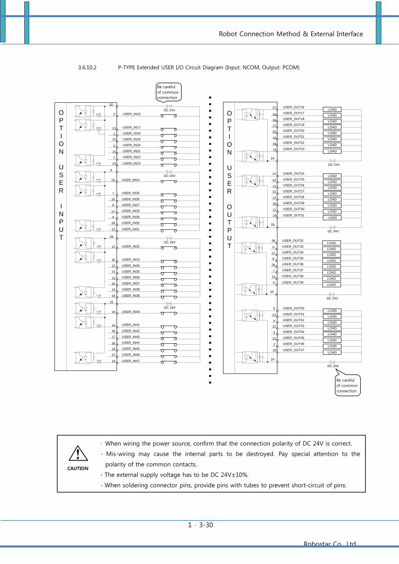
Robot Connection Method & External Interface
1 - 3-30
Robostar Co., Ltd
3.6.10.2 P-TYPE Extended USER I/O Circuit Diagram (Input: NCOM, Output: PCOM)
LOAD
LOAD
DC 24V
LOAD
LOAD
LOAD
LOAD
LOAD
LOAD
LOAD
LOAD
DC 24V
LOAD
LOAD
LOAD
LOAD
LOAD
LOAD
19
37
18
36
17
35
16
34
15
33
14
32
13
31
12
30
11
29
USER_OUT16
USER_OUT21
USER_OUT17
USER_OUT18
USER_OUT19
USER_OUT20
USER_OUT22
USER_OUT23
USER_OUT24
USER_OUT29
USER_OUT25
USER_OUT26
USER_OUT27
USER_OUT28
USER_OUT30
USER_OUT31
2
21
3
22
5
23
7
24
DC 24V
20
USER_IN16
USER_IN21
USER_IN17
USER_IN18
USER_IN19
USER_IN20
USER_IN22
USER_IN23
4.7K
4.7K
4.7K
DC 24V
4.7K
4.7K
4.7K
USER_IN24
USER_IN29
USER_IN25
USER_IN26
USER_IN27
USER_IN28
USER_IN30
USER_IN31
25
7
26
8
27
9
28
10
6
O
P
T
I
O
N
U
S
E
R
I
N
P
U
T
O
P
T
I
O
N
U
S
E
R
O
U
T
P
U
TDC 24V
4.7K
4.7K
4.7K
USER_IN32
USER_IN37
USER_IN33
USER_IN34
USER_IN35
USER_IN36
USER_IN38
USER_IN39
11
30
12
31
13
32
14
33
29
DC 24V
4.7K
4.7K
4.7K
USER_IN40
USER_IN45
USER_IN41
USER_IN42
USER_IN43
USER_IN44
USER_IN46
USER_IN47
34
16
35
17
36
18
37
19
15
LOAD
LOAD
DC 24V
LOAD
LOAD
LOAD
LOAD
LOAD
LOAD
10
28
9
27
8
26
7
25
6
USER_OUT32
USER_OUT37
USER_OUT33
USER_OUT34
USER_OUT35
USER_OUT36
USER_OUT38
USER_OUT39
LOAD
LOAD
DC 24V
LOAD
LOAD
LOAD
LOAD
LOAD
LOAD
24
5
23
4
22
3
21
2
20
USER_OUT40
USER_OUT45
USER_OUT41
USER_OUT42
USER_OUT43
USER_OUT44
USER_OUT46
USER_OUT47
Be careful
of common
connection
Be careful
of common
connection
∙ When wiring the power source, confirm that the connection polarity of DC 24V is correct.
∙ Mis-wiring may cause the internal parts to be destroyed. Pay special attention to the
polarity of the common contacts.
∙ The external supply voltage has to be DC 24V±10%.
∙ When soldering connector pins, provide pins with tubes to prevent short-circuit of pins.
CAUTION
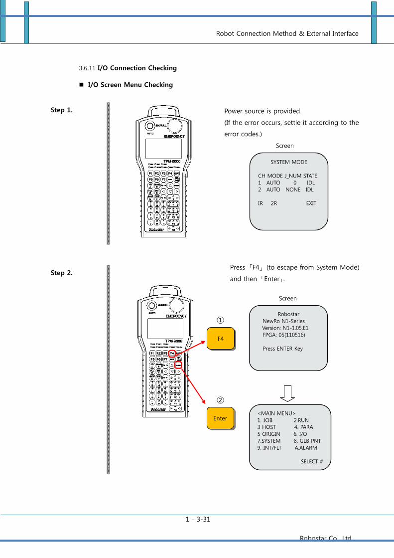
Robot Connection Method & External Interface
1 - 3-31
Robostar Co., Ltd
3.6.11 I/O Connection Checking
I/O Screen Menu Checking
Step 1.
Step 2.
Enter
F4
①
②
Power source is provided.
(If the error occurs, settle it according to the
error codes.)
Screen
Display SYSTEM MODE
CH MODE J_NUM STATE
1 AUTO 0 IDL
2 AUTO NONE IDL
IR 2R EXIT
Press 「F4」 (to escape from System Mode)
and then 「Enter」.
Screen
Display
<MAIN MENU>
1. JOB 2.RUN
3 HOST 4. PARA
5 ORIGIN 6. I/O
7.SYSTEM 8. GLB PNT
9. INT/FLT A.ALARM
SELECT #
Robostar
NewRo N1-Series
Version: N1-1.05.E1
FPGA: 05(110516)
Press ENTER Key
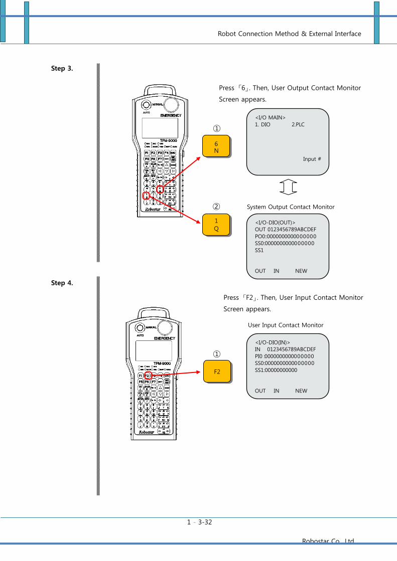
Robot Connection Method & External Interface
1 - 3-32
Robostar Co., Ltd
Step 3.
Step 4.
1
Q
F2
①
②
①
6
N
Press 「6」. Then, User Output Contact Monitor
Screen appears.
System Output Contact Monitor
Screen
Press 「F2」. Then, User Input Contact Monitor
Screen appears.
User Input Contact Monitor
Screen
<I/O MAIN>
1. DIO 2.PLC
Input #
<I/O-DIO(OUT)>
OUT 0123456789ABCDEF
PO0:0000000000000000
SS0:0000000000000000
SS1
OUT IN NEW
<I/O-DIO(IN)>
IN 0123456789ABCDEF
PI0 :0000000000000000
SS0:0000000000000000
SS1:00000000000
OUT IN NEW
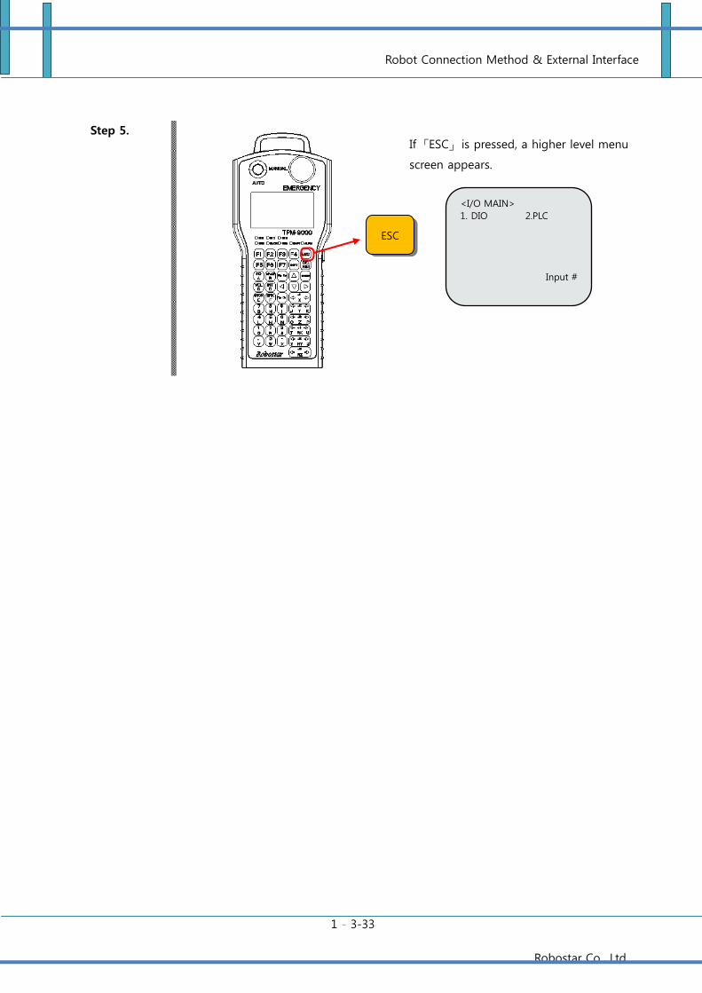
Robot Connection Method & External Interface
1 - 3-33
Robostar Co., Ltd
Step 5.
ESC
If 「ESC」 is pressed, a higher level menu
screen appears.
<I/O MAIN>
1. DIO 2.PLC
Input #
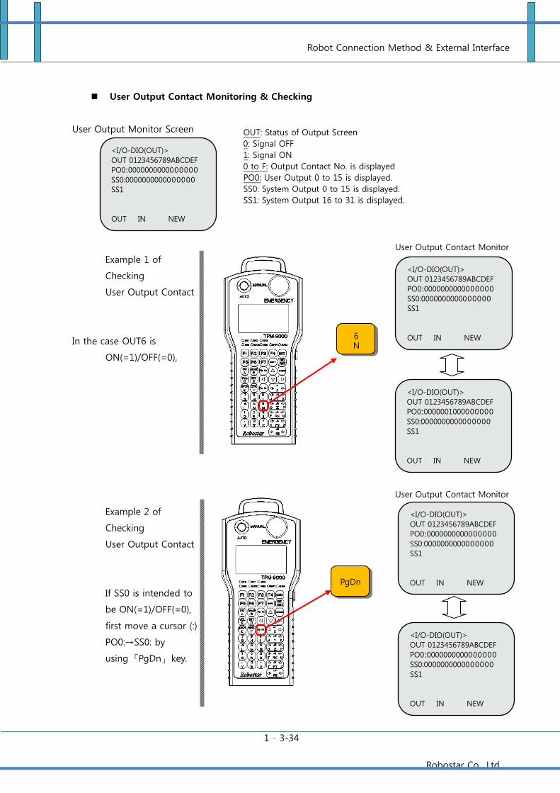
Robot Connection Method & External Interface
1 - 3-34
Robostar Co., Ltd
User Output Contact Monitoring & Checking
User Output Monitor Screen
Example 1 of
Checking
User Output Contact
In the case OUT6 is
ON(=1)/OFF(=0),
Example 2 of
Checking
User Output Contact
If SS0 is intended to
be ON(=1)/OFF(=0),
first move a cursor (:)
PO0:→SS0: by
using 「PgDn」 key.
OUT: Status of Output Screen
0: Signal OFF
1: Signal ON
0 to F: Output Contact No. is displayed
PO0: User Output 0 to 15 is displayed.
SS0: System Output 0 to 15 is displayed.
SS1: System Output 16 to 31 is displayed.
PgDn
<I/O-DIO(OUT)>
OUT 0123456789ABCDEF
PO0:0000000000000000
SS0:0000000000000000
SS1
OUT IN NEW
User Output Contact Monitor
Screen
User Output Contact Monitor
Screen
6
N
<I/O-DIO(OUT)>
OUT 0123456789ABCDEF
PO0:0000000000000000
SS0:0000000000000000
SS1
OUT IN NEW
<I/O-DIO(OUT)>
OUT 0123456789ABCDEF
PO0:0000001000000000
SS0:0000000000000000
SS1
OUT IN NEW
<I/O-DIO(OUT)>
OUT 0123456789ABCDEF
PO0:0000000000000000
SS0:0000000000000000
SS1
OUT IN NEW
<I/O-DIO(OUT)>
OUT 0123456789ABCDEF
PO0:0000000000000000
SS0:0000000000000000
SS1
OUT IN NEW
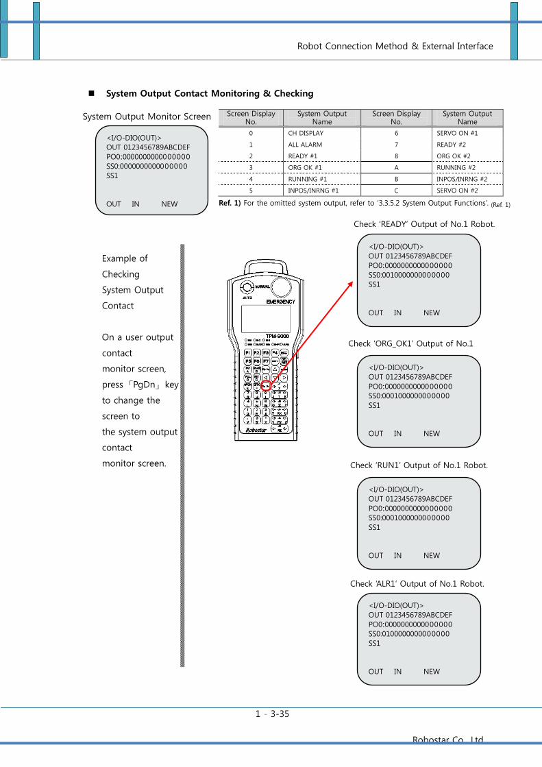
Robot Connection Method & External Interface
1 - 3-35
Robostar Co., Ltd
System Output Contact Monitoring & Checking
System Output Monitor Screen
Example of
Checking
System Output
Contact
On a user output
contact
monitor screen,
press 「PgDn」 key
to change the
screen to
the system output
contact
monitor screen.
Screen Display No.
System Output Name
Screen Display No.
System Output Name
0 CH DISPLAY 6 SERVO ON #1
1 ALL ALARM 7 READY #2
2 READY #1 8 ORG OK #2
3 ORG OK #1 A RUNNING #2
4 RUNNING #1 B INPOS/INRNG #2
5 INPOS/INRNG #1 C SERVO ON #2
Ref. 1) For the omitted system output, refer to ‘3.3.5.2 System Output Functions’. (Ref. 1)
<I/O-DIO(OUT)>
OUT 0123456789ABCDEF
PO0:0000000000000000
SS0:0000000000000000
SS1
OUT IN NEW
Check ‘READY’ Output of No.1 Robot.
Robot.
Check ‘ORG_OK1’ Output of No.1
Robot. t.
Check ‘RUN1’ Output of No.1 Robot.
Check ‘ALR1’ Output of No.1 Robot.
<I/O-DIO(OUT)>
OUT 0123456789ABCDEF
PO0:0000000000000000
SS0:0010000000000000
SS1
OUT IN NEW
<I/O-DIO(OUT)>
OUT 0123456789ABCDEF
PO0:0000000000000000
SS0:0001000000000000
SS1
OUT IN NEW
<I/O-DIO(OUT)>
OUT 0123456789ABCDEF
PO0:0000000000000000
SS0:0001000000000000
SS1
OUT IN NEW
<I/O-DIO(OUT)>
OUT 0123456789ABCDEF
PO0:0000000000000000
SS0:0100000000000000
SS1
OUT IN NEW
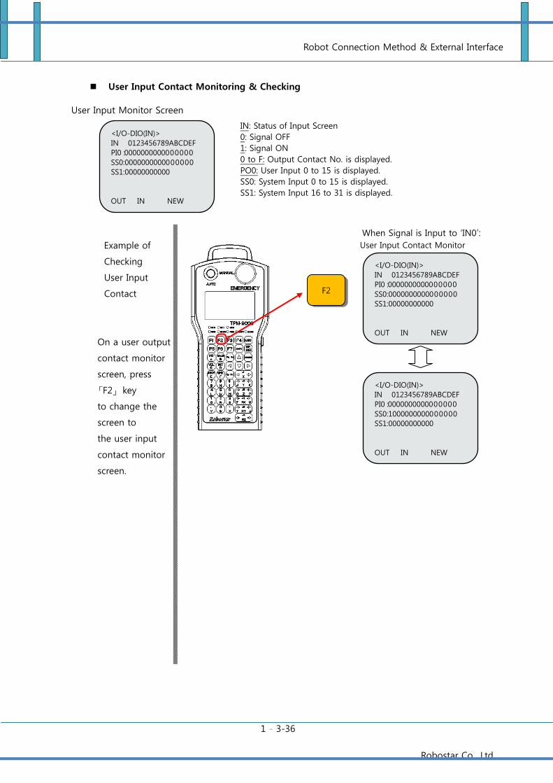
Robot Connection Method & External Interface
1 - 3-36
Robostar Co., Ltd
User Input Contact Monitoring & Checking
User Input Monitor Screen
Example of
Checking
User Input
Contact
On a user output
contact monitor
screen, press
「F2」 key
to change the
screen to
the user input
contact monitor
screen.
IN: Status of Input Screen
0: Signal OFF
1: Signal ON
0 to F: Output Contact No. is displayed.
PO0: User Input 0 to 15 is displayed.
SS0: System Input 0 to 15 is displayed.
SS1: System Input 16 to 31 is displayed.
<I/O-DIO(IN)>
IN 0123456789ABCDEF
PI0 :0000000000000000
SS0:0000000000000000
SS1:00000000000
OUT IN NEW
When Signal is Input to ‘IN0’:
User Input Contact Monitor
Screen <I/O-DIO(IN)>
IN 0123456789ABCDEF
PI0 :0000000000000000
SS0:0000000000000000
SS1:00000000000
OUT IN NEW
<I/O-DIO(IN)>
IN 0123456789ABCDEF
PI0 :0000000000000000
SS0:1000000000000000
SS1:00000000000
OUT IN NEW
F2
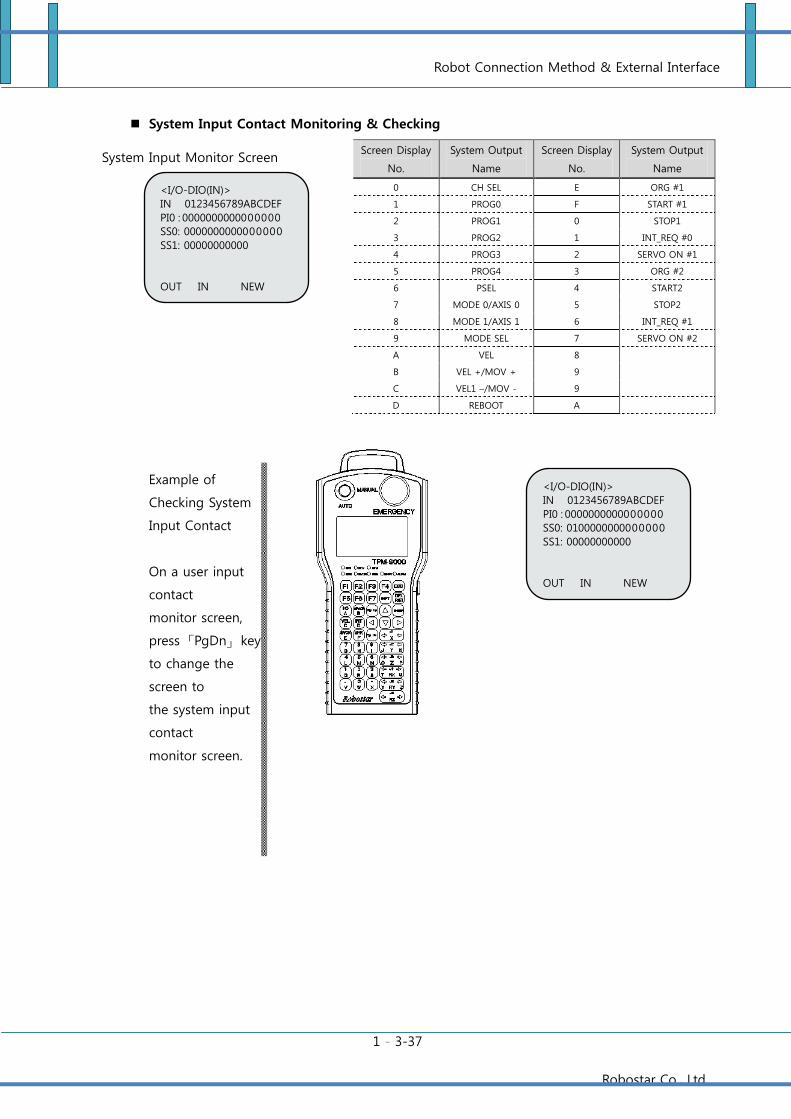
Robot Connection Method & External Interface
1 - 3-37
Robostar Co., Ltd
System Input Contact Monitoring & Checking
System Input Monitor Screen
Example of
Checking System
Input Contact
On a user input
contact
monitor screen,
press 「PgDn」 key
to change the
screen to
the system input
contact
monitor screen.
Screen Display
No.
System Output
Name
Screen Display
No.
System Output
Name
0 CH SEL E ORG #1
1 PROG0 F START #1
2 PROG1 0 STOP1
3 PROG2 1 INT_REQ #0
4 PROG3 2 SERVO ON #1
5 PROG4 3 ORG #2
6 PSEL 4 START2
7 MODE 0/AXIS 0 5 STOP2
8 MODE 1/AXIS 1 6 INT_REQ #1
9 MODE SEL 7 SERVO ON #2
A VEL 8
B VEL +/MOV + 9
C VEL1 –/MOV - 9
D REBOOT A
Ref. 1) 생략한 System Input은 ‘3.3.5.1 System Input 기능’을 참고바랍니다.
‘PROG0’ Input 확인
<I/O-DIO(IN)>
IN 0123456789ABCDEF
PI0 : 0000000000000000
SS0: 0000000000000000
SS1: 00000000000
OUT IN NEW
<I/O-DIO(IN)>
IN 0123456789ABCDEF
PI0 : 0000000000000000
SS0: 0100000000000000
SS1: 00000000000
OUT IN NEW
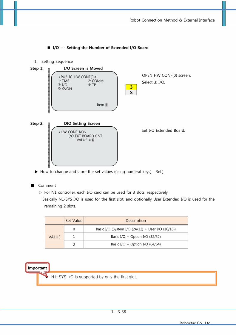
Robot Connection Method & External Interface
1 - 3-38
Robostar Co., Ltd
3S
I/O --- Setting the Number of Extended I/O Board
1. Setting Sequence
Step 1. I/O Screen is Moved
Step 2. DIO Setting Screen
How to change and store the set values (using numeral keys) Ref.)
Comment
▷ For N1 controller, each I/O card can be used for 3 slots, respectively.
Basically N1-SYS I/O is used for the first slot, and optionally User Extended I/O is used for the
remaining 2 slots.
Set Value Description
VALUE
0 Basic I/O (System I/O (24/12) + User I/O (16/16))
1 Basic I/O + Option I/O (32/32)
2 Basic I/O + Option I/O (64/64)
<PUBLIC-HW CONF(0)> 1: TMR 2: COMM 3: I/O 4: TP 5: SVON
item #
OPEN HW CONF(0) screen.
Select 3: I/O.
<HW CONF-I/O> I/O EXT BOARD CNT
VALUE = 0
Set I/O Extended Board.
N1-SYS I/O is supported by only the first slot.
Important
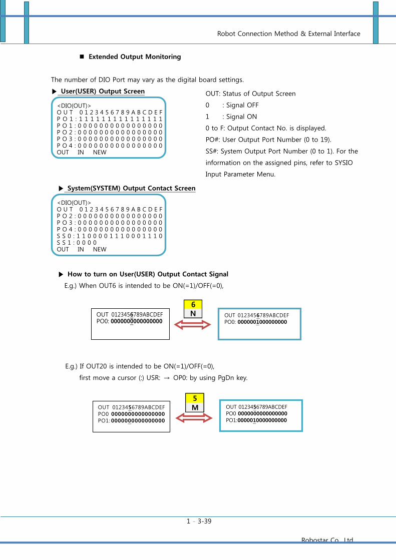
Robot Connection Method & External Interface
1 - 3-39
Robostar Co., Ltd
6N
5
M
Extended Output Monitoring
The number of DIO Port may vary as the digital board settings.
User(USER) Output Screen
System(SYSTEM) Output Contact Screen
How to turn on User(USER) Output Contact Signal
E.g.) When OUT6 is intended to be ON(=1)/OFF(=0),
E.g.) If OUT20 is intended to be ON(=1)/OFF(=0),
first move a cursor (:) USR: → OP0: by using PgDn key.
<DIO(OUT)> O U T 0 1 2 3 4 5 6 7 8 9 A B C D E F P O 2 : 0 0 0 0 0 0 0 0 0 0 0 0 0 0 0 0 P O 3 : 0 0 0 0 0 0 0 0 0 0 0 0 0 0 0 0 P O 4 : 0 0 0 0 0 0 0 0 0 0 0 0 0 0 0 0 S S 0 : 1 1 0 0 0 0 1 1 1 0 0 0 1 1 1 0 S S 1 : 0 0 0 0 0 0 0 0 0 0 0 0 0 0 0 0 OUT IN NEW
<DIO(OUT)> O U T 0 1 2 3 4 5 6 7 8 9 A B C D E F P O 1 : 1 1 1 1 1 1 1 1 1 1 1 1 1 1 1 P O 1 : 0 0 0 0 0 0 0 0 0 0 0 0 0 0 0 0 P O 2 : 0 0 0 0 0 0 0 0 0 0 0 0 0 0 0 0 P O 3 : 0 0 0 0 0 0 0 0 0 0 0 0 0 0 0 0 P O 4 : 0 0 0 0 0 0 0 0 0 0 0 0 0 0 0 0 OUT IN NEW
OUT: Status of Output Screen
0 : Signal OFF
1 : Signal ON
0 to F: Output Contact No. is displayed.
PO#: User Output Port Number (0 to 19).
SS#: System Output Port Number (0 to 1). For the
information on the assigned pins, refer to SYSIO
Input Parameter Menu.
OUT 0123456789ABCDEF PO0: 0000000000000000
OUT 0123456789ABCDEF PO0: 0000001000000000
OUT 0123456789ABCDEF PO0 0000000000000000
PO1: 0000010000000000
OUT 0123456789ABCDEF
PO0 0000000000000000 PO1: 0000000000000000
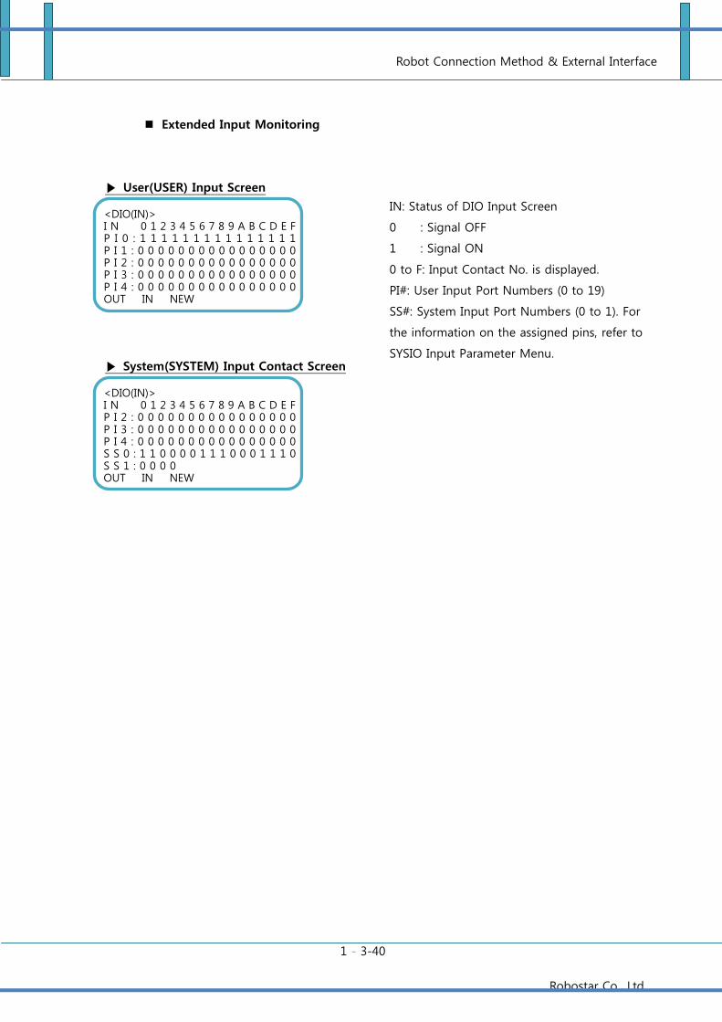
Robot Connection Method & External Interface
1 - 3-40
Robostar Co., Ltd
Extended Input Monitoring
User(USER) Input Screen
System(SYSTEM) Input Contact Screen
<DIO(IN)> I N 0 1 2 3 4 5 6 7 8 9 A B C D E F P I 2 : 0 0 0 0 0 0 0 0 0 0 0 0 0 0 0 0 P I 3 : 0 0 0 0 0 0 0 0 0 0 0 0 0 0 0 0 P I 4 : 0 0 0 0 0 0 0 0 0 0 0 0 0 0 0 0 S S 0 : 1 1 0 0 0 0 1 1 1 0 0 0 1 1 1 0 S S 1 : 0 0 0 0 0 0 0 0 0 0 0 0 0 0 0 0 OUT IN NEW
<DIO(IN)> I N 0 1 2 3 4 5 6 7 8 9 A B C D E F P I 0 : 1 1 1 1 1 1 1 1 1 1 1 1 1 1 1 P I 1 : 0 0 0 0 0 0 0 0 0 0 0 0 0 0 0 0 P I 2 : 0 0 0 0 0 0 0 0 0 0 0 0 0 0 0 0 P I 3 : 0 0 0 0 0 0 0 0 0 0 0 0 0 0 0 0 P I 4 : 0 0 0 0 0 0 0 0 0 0 0 0 0 0 0 0 OUT IN NEW
IN: Status of DIO Input Screen
0 : Signal OFF
1 : Signal ON
0 to F: Input Contact No. is displayed.
PI#: User Input Port Numbers (0 to 19)
SS#: System Input Port Numbers (0 to 1). For
the information on the assigned pins, refer to
SYSIO Input Parameter Menu.
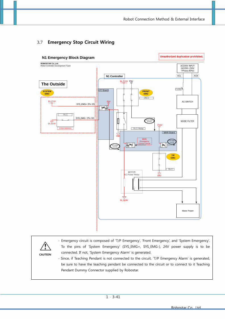
Robot Connection Method & External Interface
1 - 3-41
Robostar Co., Ltd
3.7 Emergency Stop Circuit Wiring
N1 Controller
ROBOSTAR Co.,Ltd.
Robot Controller Development Team
Unauthorized duplication prohibited.N1 Emergency Block Diagram
MOTOR AC Power Relay
IN_G24V
IN_P24V
2N.C
P5V
1
1N.O Relay
EX_P24V
SYS_EMG- (Pin 50)
SYSTEM
EMG
EX_G24V
MAIN Emergency
Control Circuit
1N.C
GND
P15V
T/P EMG
STATE
I/O Board
MAIN Board
AC220V INPUT(AC200~230V1Phase,60Hz)
Motor Power
ACL ACN
AC SWITCH
NOISE FILTER
FUSE
SYS_EMG+ (Pin 25)
GND
FRONT
EMG
T/P
EMG
P5V
The Outside
Front EMG
STATE
SYS EMG
STATE
1N.C
SYSTEM EMERGENCY
∙ Emergency circuit is composed of ‘T/P Emergency’, ‘Front Emergency’, and ‘System Emergency’.
To the pins of ‘System Emergency’ (SYS_EMG+, SYS_EMG-), 24V power supply is to be
connected. If not, ‘System Emergency Alarm’ is generated.
∙ Since, if Teaching Pendant is not connected to the circuit, ‘T/P Emergency Alarm’ is generated,
be sure to have the teaching pendant be connected to the circuit or to connect to it Teaching
Pendant Dummy Connector supplied by Robostar.
CAUTION
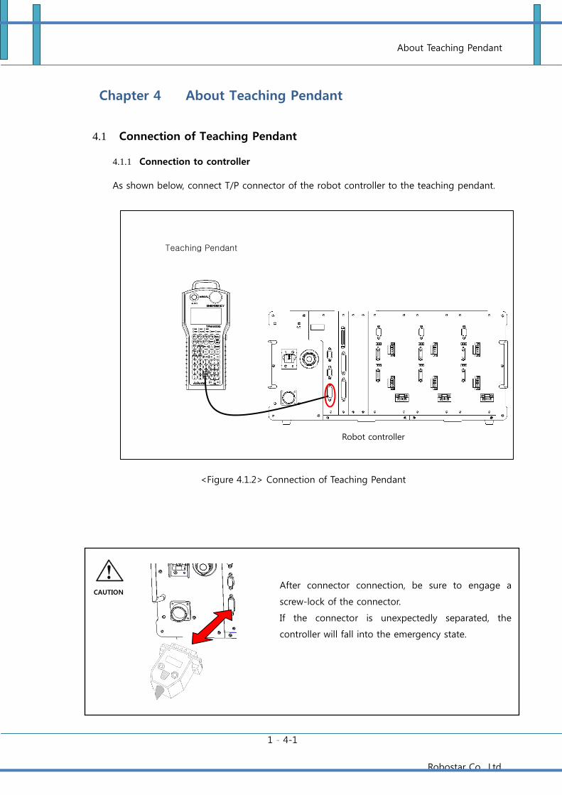
About Teaching Pendant
1 - 4-1
Robostar Co., Ltd
Chapter 4 About Teaching Pendant
4.1 Connection of Teaching Pendant
4.1.1 Connection to controller
As shown below, connect T/P connector of the robot controller to the teaching pendant.
<Figure 4.1.2> Connection of Teaching Pendant
After connector connection, be sure to engage a
screw-lock of the connector.
If the connector is unexpectedly separated, the
controller will fall into the emergency state.
Teaching Pendant
Robot controller
CAUTION
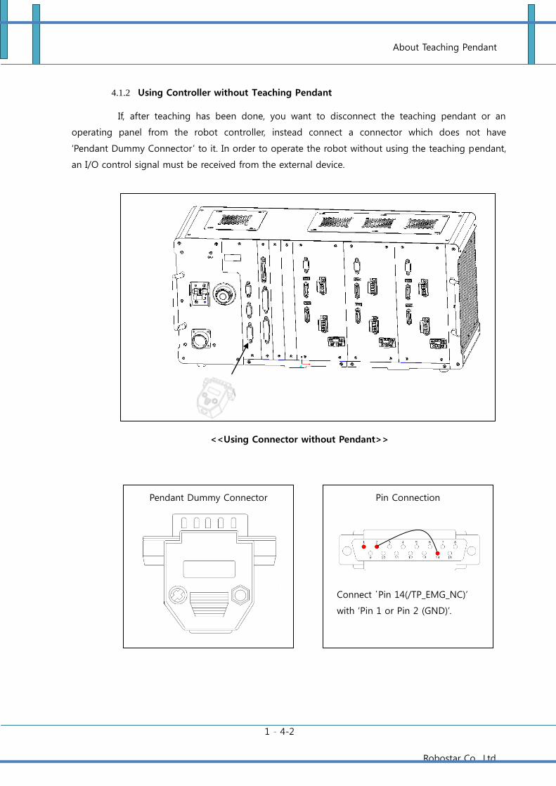
About Teaching Pendant
1 - 4-2
Robostar Co., Ltd
4.1.2 Using Controller without Teaching Pendant
If, after teaching has been done, you want to disconnect the teaching pendant or an
operating panel from the robot controller, instead connect a connector which does not have
‘Pendant Dummy Connector’ to it. In order to operate the robot without using the teaching pendant,
an I/O control signal must be received from the external device.
<<Using Connector without Pendant>>
Pendant Dummy Connector Pin Connection
Connect ‘Pin 14(/TP_EMG_NC)’
with ‘Pin 1 or Pin 2 (GND)’.
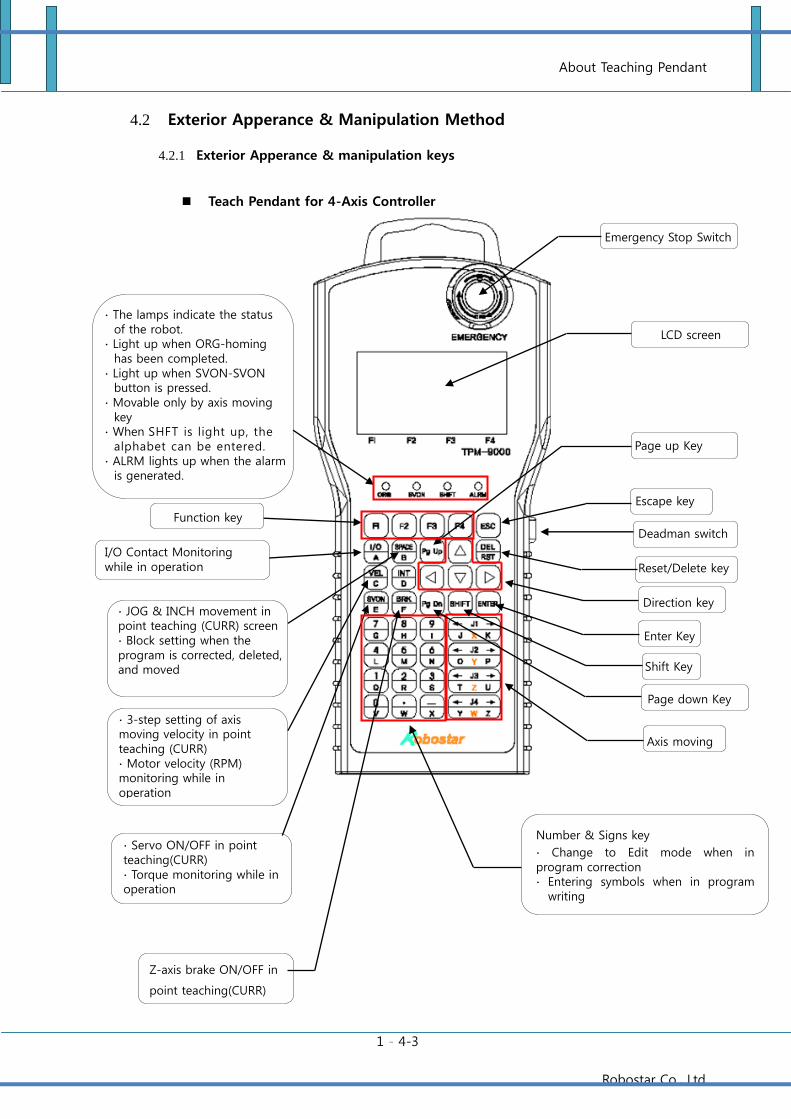
About Teaching Pendant
1 - 4-3
Robostar Co., Ltd
4.2 Exterior Apperance & Manipulation Method
4.2.1 Exterior Apperance & manipulation keys
Teach Pendant for 4-Axis Controller
Reset/Delete key
LCD screen
Page up Key
Direction key
Enter Key
Deadman switch
∙ Servo ON/OFF in point teaching(CURR) ∙ Torque monitoring while in operation
Z-axis brake ON/OFF in
point teaching(CURR)
Function key
I/O Contact Monitoring while in operation
∙ JOG & INCH movement in point teaching (CURR) screen ∙ Block setting when the program is corrected, deleted, and moved
∙ The lamps indicate the status of the robot.
∙ Light up when ORG-homing has been completed.
∙ Light up when SVON-SVON button is pressed.
∙ Movable only by axis moving key
∙ When SHFT is light up, the alphabet can be entered.
∙ ALRM lights up when the alarm is generated.
Axis moving
Shift Key
Escape key
Emergency Stop Switch
Number & Signs key
∙ Change to Edit mode when in program correction ∙ Entering symbols when in program
writing
∙ 3-step setting of axis moving velocity in point teaching (CURR) ∙ Motor velocity (RPM) monitoring while in operation
Page down Key
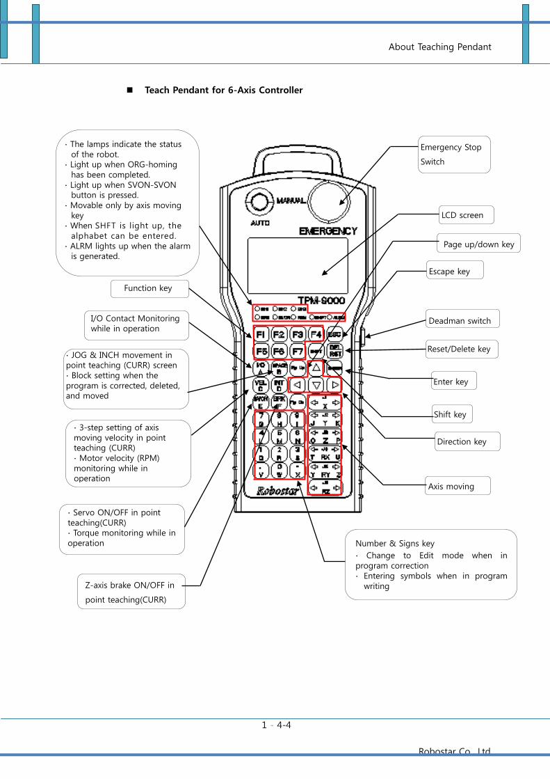
About Teaching Pendant
1 - 4-4
Robostar Co., Ltd
Teach Pendant for 6-Axis Controller
Reset/Delete key
LCD screen
Page up/down key
Direction key
Enter key
Deadman switch
∙ Servo ON/OFF in point teaching(CURR) ∙ Torque monitoring while in operation
Z-axis brake ON/OFF in
point teaching(CURR)
Function key
I/O Contact Monitoring while in operation
∙ JOG & INCH movement in point teaching (CURR) screen ∙ Block setting when the program is corrected, deleted, and moved
Axis moving
Shift key
Escape key
Emergency Stop
Switch
Number & Signs key
∙ Change to Edit mode when in program correction ∙ Entering symbols when in program
writing
∙ 3-step setting of axis moving velocity in point teaching (CURR) ∙ Motor velocity (RPM) monitoring while in operation
∙ The lamps indicate the status of the robot.
∙ Light up when ORG-homing has been completed.
∙ Light up when SVON-SVON button is pressed.
∙ Movable only by axis moving key
∙ When SHFT is light up, the alphabet can be entered.
∙ ALRM lights up when the alarm is generated.
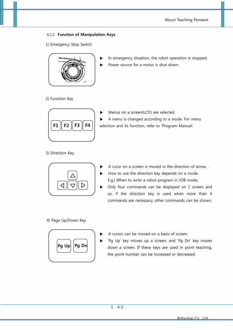
About Teaching Pendant
1 - 4-5
Robostar Co., Ltd
4.2.2 Function of Manipulation Keys
1) Emergency Stop Switch
In emergency situation, the robot operation is stopped.
Power source for a motor is shut down.
2) Function Key
Menus on a screen(LCD) are selected.
A menu is changed according to a mode. For menu
selection and its function, refer to ‘Program Manual’.
3) Direction Key
A curor on a screen is moved in the direction of arrow. .
How to use the direction key depends on a mode.
E.g.) When to write a robot program in JOB mode,
Only four commands can be displayed on 1 screen and
so, if the direction key is used when more than 4
commands are necessary, other commands can be shown.
4) Page Up/Down Key
A cursor can be moved on a basis of screen.
‘Pg Up’ key moves up a screen, and ‘Pg Dn’ key moves
down a screen. If these keys are used in point teaching,
the point number can be increased or decreased.
▷
`` ◁
F1 F2 F3 F4
Pg Up Pg Dn
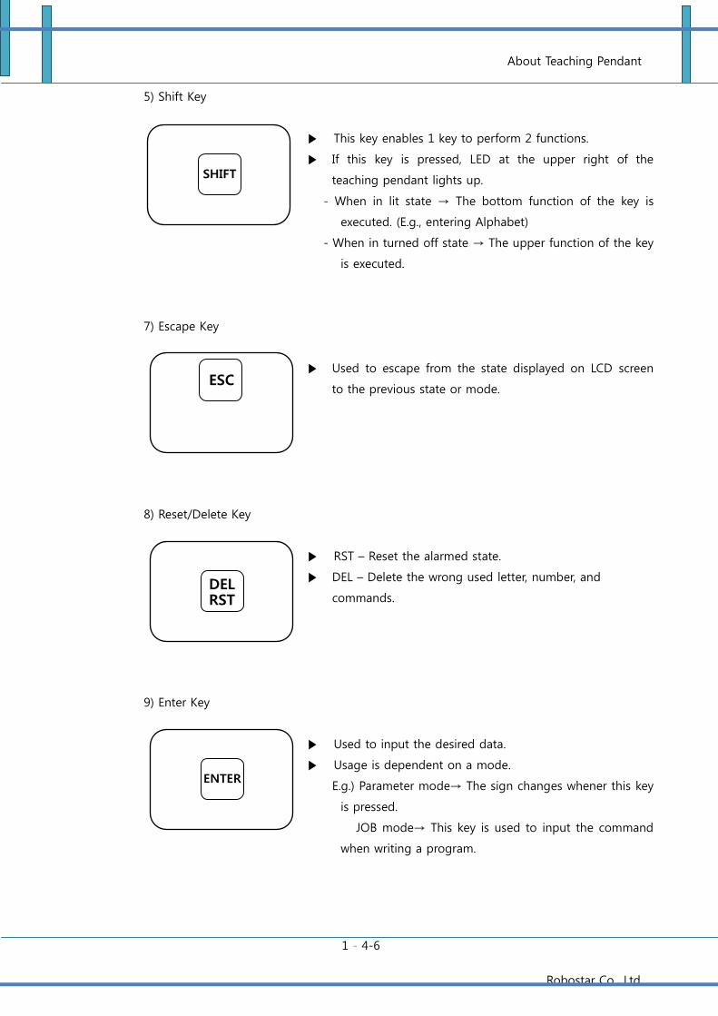
About Teaching Pendant
1 - 4-6
Robostar Co., Ltd
5) Shift Key
This key enables 1 key to perform 2 functions.
If this key is pressed, LED at the upper right of the
teaching pendant lights up.
- When in lit state → The bottom function of the key is
executed. (E.g., entering Alphabet)
- When in turned off state → The upper function of the key
is executed.
7) Escape Key
Used to escape from the state displayed on LCD screen
to the previous state or mode.
8) Reset/Delete Key
RST – Reset the alarmed state.
DEL – Delete the wrong used letter, number, and
commands.
9) Enter Key
Used to input the desired data.
Usage is dependent on a mode.
E.g.) Parameter mode→ The sign changes whener this key
is pressed.
JOB mode→ This key is used to input the command
when writing a program.
DEL RST
ESC
ENTER
SHIFT
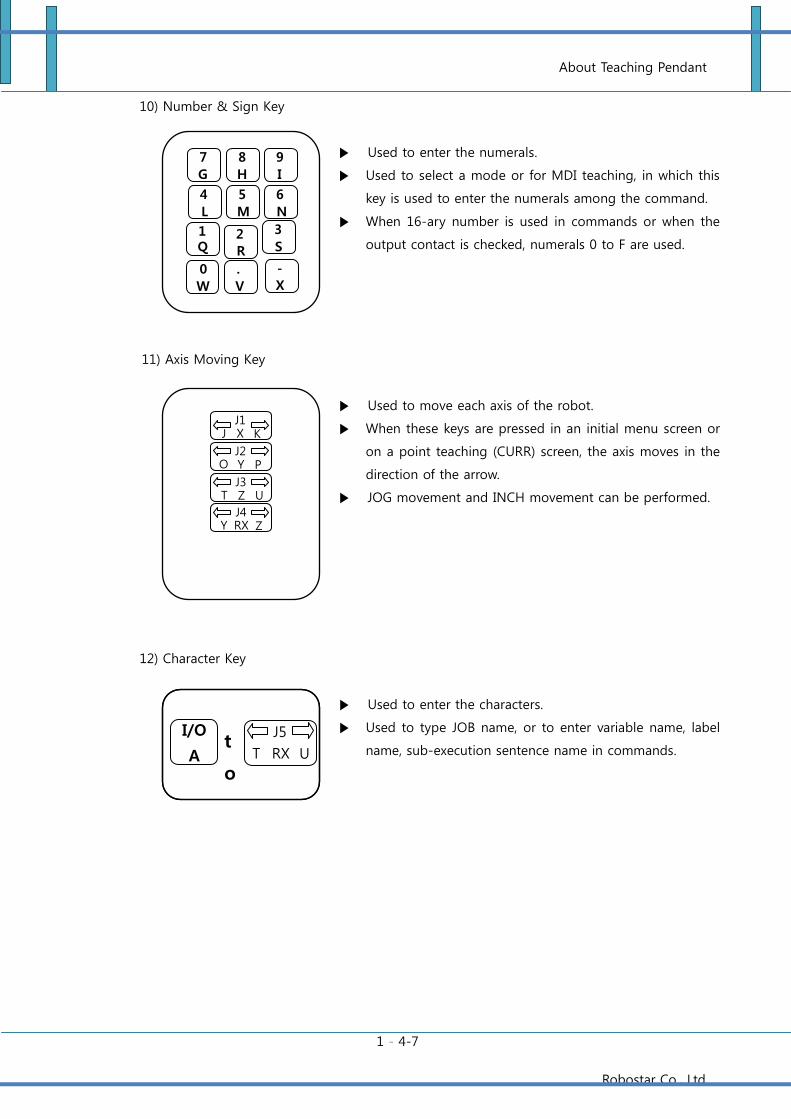
About Teaching Pendant
1 - 4-7
Robostar Co., Ltd
10) Number & Sign Key
Used to enter the numerals.
Used to select a mode or for MDI teaching, in which this
key is used to enter the numerals among the command.
When 16-ary number is used in commands or when the
output contact is checked, numerals 0 to F are used.
11) Axis Moving Key
Used to move each axis of the robot.
When these keys are pressed in an initial menu screen or
on a point teaching (CURR) screen, the axis moves in the
direction of the arrow.
JOG movement and INCH movement can be performed.
12) Character Key
Used to enter the characters.
Used to type JOB name, or to enter variable name, label
name, sub-execution sentence name in commands.
7
G 8
H
5
M
.
V
3
S 2
R
6
N
9
I
4
L
1 Q
J1 X J K
J2 Y O P
J3 Z T U
J4 RX Y Z
I/O
A
J5
RX T U t
o
0
W -
X
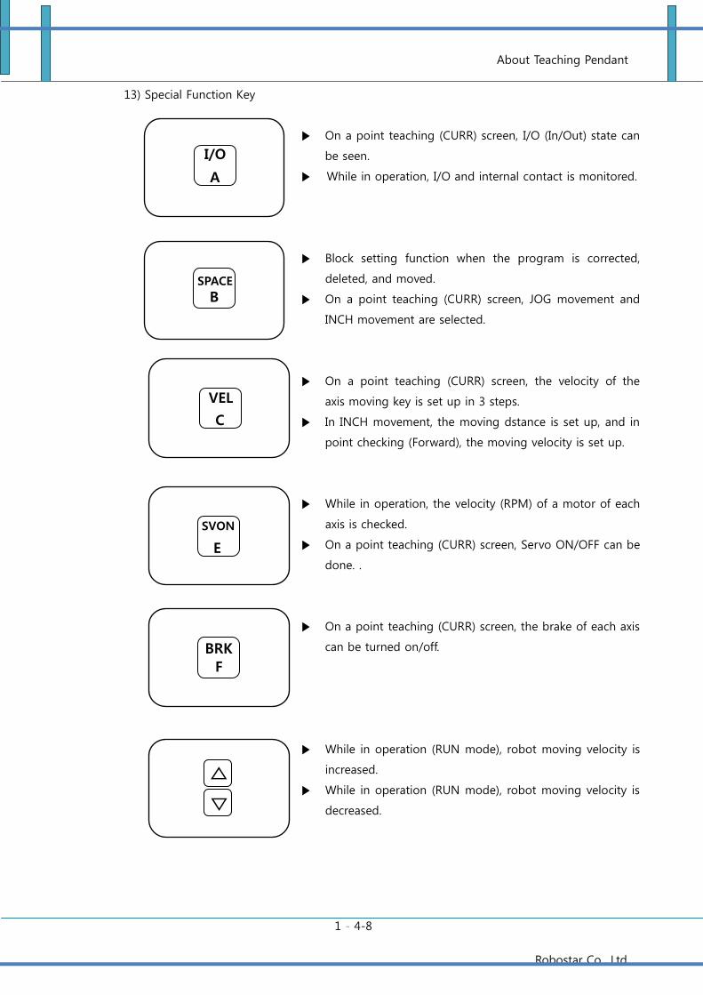
About Teaching Pendant
1 - 4-8
Robostar Co., Ltd
13) Special Function Key
On a point teaching (CURR) screen, I/O (In/Out) state can
be seen.
While in operation, I/O and internal contact is monitored.
Block setting function when the program is corrected,
deleted, and moved.
On a point teaching (CURR) screen, JOG movement and
INCH movement are selected.
On a point teaching (CURR) screen, the velocity of the
axis moving key is set up in 3 steps.
In INCH movement, the moving dstance is set up, and in
point checking (Forward), the moving velocity is set up.
While in operation, the velocity (RPM) of a motor of each
axis is checked.
On a point teaching (CURR) screen, Servo ON/OFF can be
done. .
On a point teaching (CURR) screen, the brake of each axis
can be turned on/off.
While in operation (RUN mode), robot moving velocity is
increased.
While in operation (RUN mode), robot moving velocity is
decreased.
I/O
A
VEL
C
SVON
E
``
SPACE
B
BRK
F
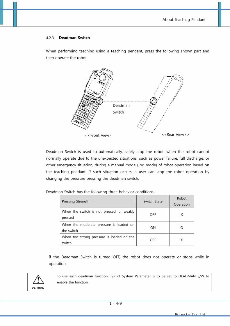
About Teaching Pendant
1 - 4-9
Robostar Co., Ltd
4.2.3 Deadman Switch
When performing teaching using a teaching pendant, press the following shown part and
then operate the robot.
Deadman Switch is used to automatically, safely stop the robot, when the robot cannot
normally operate due to the unexpected situations, such as power failure, full discharge, or
other emergency situation, during a manual mode (Jog mode) of robot operation based on
the teaching pendant. If such situation occurs, a user can stop the robot operation by
changing the pressure pressing the deadman switch.
Deadman Switch has the following three behavior conditions.
Pressing Strength Switch State Robot
Operation
When the switch is not pressed, or weakly
pressed OFF X
When the moderate pressure is loaded on
the switch ON O
When too strong pressure is loaded on the
switch OFF X
If the Deadman Switch is turned OFF, the robot does not operate or stops while in
operation.
To use such deadman function, T/P of System Parameter is to be set to DEADMAN S/W to
enable the function.
<<Front View>
<<Rear View>>
Deadman
Switch
CAUTION
About Teaching Pendant
1 - 5-10
Robostar Co., Ltd
Chapter 5 Controller Alarm Code Table
5.1 File System Alarms
File System Alarms
Code Num T/P DISPLAY Description Alarm clearing
E1001 File System Error Damaged file system RESET
E1002 Directory Full File directory is full RESET
E1003 Out of Memory Insufficient memory for execution of Job RESET
E1004 Same File Name Ext There are different Jobs having the same name RESET
E1005 Bad File Damaged file system RESET
E1006 Disk Full Insufficient space for storage of Job RESET
E1007 PROG Delete Error Job file does not exist RESET
E1008 POINT Delete Error PNT file does not exist RESET
E1009 PROG Copy Error Job file cannot be copied RESET
E1010 POINT Copy Error PNT file cannot be copied RESET
E1013 There Is No Job Job file does not exist or damaged RESET
E1018 Para Load Fail Parameter structure damaged RESET
E1019 Bad Parameter Data Parameter value damaged RESET
E1020 STR buff overflow 300 or more character variables and character constants are used for each
channel RESET
E1021 Line buff overflow The length of text string of character variable and character constant exceeds 100
letters RESET
5.2 Protective Alarms
Protective Alarms
Code Num T/P DISPLAY Description Alarm clearing
E1101 S/W Limit Deviation from the operation range of the robot parameter (Range) RESET
E1102 Inpos. Error A motor does not stop within the regular time RESET
E1103 H/W Limit H/W limit sensor signal is detected RESET
E1104 Servo Not Ready Servo ON is actuated when a servo module has not been yet initialized. RESET
E1105 Torque Limit While TRQ command is used, the setup value is higher than the actual torque
value RESET
E1151 System Emergency Emergently stop because of manipulation of system I/O RESET
E1152 Front Emergency Emergently stopped by a front panel emergency stop switch RESET
E1153 T/P Emergency Emergently stopped by an emergency stop switch of the teaching pendant RESET
E1154 Host Emergency Emergently stopped by an emergency stop protocol in Host mode RESET
E1163 Enc count Alarm Encoder value of a motor abruptly changes over the permissible value. RESET
E1165 Ref count Alarm Positional error due to operation error of a controller RESET
E1168 Servo ON POS Error Amount of rotation of a motor exceeds the permissible value when in Servo ON RESET
E1169 TASK EXIT FAIL Abnormal system task in the controller POWER ON/OFF
About Teaching Pendant
1 - 5-11
Robostar Co., Ltd
5.3 Run Time Alarms
Run Time Alarms
Code Num T/P DISPLAY Description Alarm clearing
E1201 File Not Found JCALL’ed, but Job does not exist RESET
E1202 Range Over Values of command and variable index are out of permissible range RESET
E1203 Invers Error Error arising in inversion of XY mode (X,Y,Z,W) into Joint (A,B,Z,W) in a horizontal
articulated robot RESET
E1204 Not Teaching Point Error arising when in use of a point which has not been taught RESET
E1205 Job Depth Over JCALL is continuously used, exceeding the regular times (3 times) RESET
E1206 CALL Depth Over CALL is continuously used, exceeding the regular times (8 times) RESET
E1207 Invalid FOS Error Improper use of FOS command RESET
E1208 Format Error Factors of a command are not the specified value RESET
E1209 Pallet Data Error Improper pallet data RESET
E1210 Unreachable Point A point that the robot cannot move to has been taught RESET
E1211 EXIT Instruction When EXIT command is executed RESET
E1212 POS Variable Error Wrong use of POS variable RESET
E1213 JCALL Error Insufficient memory during the robot Job operation RESET
E1214 Not Support function When motion-related commands are executed, use of the robot is not set up RESET
E1216 Source Line Error There are no commands in the executed Job RESET
E1217 Passing PLT Over The number of uses of PASS command is exceeded. RESET
E1219 Range Over Axis1 AXIS Deviate from Axis 1 setup range RESET
E1220 Range Over Axis2 AXIS Deviate from Axis 2 setup range RESET
E1221 Range Over Axis3 AXIS Deviate from Axis 3 setup range RESET
E1222 Range Over Axis4 AXIS Deviate from Axis 4 setup range RESET
E1223 Range Over Axis5 AXIS Deviate from Axis 5 setup range RESET
E1224 Range Over Axis6 AXIS Deviate from Axis 6 setup range RESET
E1225 Not ready start Job loading is not completed. RESET
E1226 Please Origin Error requiring the origin searching RESET
E1227 Invalid Parameter Insufficient number of variables of the string command RESET
E1228 Invalid string leng Text string and the number of extracted letters does not correspond to each
other in String Command RESET
E1230 Comm buf overflow The received number of the text string is more than the specified text string RESET
E1231 LPOS Read Timeout Time to read the latched position data is longer than the specified time RESET
E1232 Latch Sequence Err Latch commands are not executed in the determined order. RESET
E1233 Data Miss match SLV1 Point data of Master and Slave of synchronizing axes do not match RESET
E1234 Data Miss match SLV2 Point data of Master and Slave of synchronizing axes do not match RESET
E1235 Data Miss match SLV3 Point data of Master and Slave of synchronizing axes do not match RESET
E1237 Not find Fieldbus Setups of Fieldbus card and system parameters (FDBUS-CARD) are not identical RESET
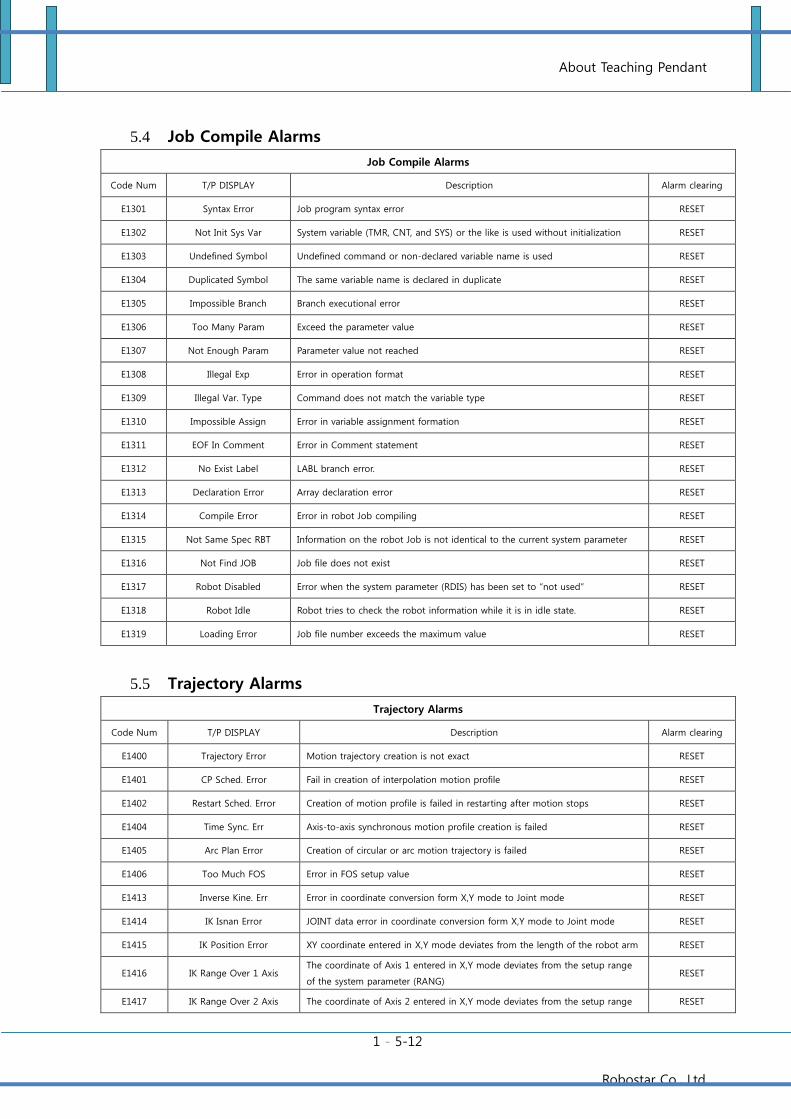
About Teaching Pendant
1 - 5-12
Robostar Co., Ltd
5.4 Job Compile Alarms
Job Compile Alarms
Code Num T/P DISPLAY Description Alarm clearing
E1301 Syntax Error Job program syntax error RESET
E1302 Not Init Sys Var System variable (TMR, CNT, and SYS) or the like is used without initialization RESET
E1303 Undefined Symbol Undefined command or non-declared variable name is used RESET
E1304 Duplicated Symbol The same variable name is declared in duplicate RESET
E1305 Impossible Branch Branch executional error RESET
E1306 Too Many Param Exceed the parameter value RESET
E1307 Not Enough Param Parameter value not reached RESET
E1308 Illegal Exp Error in operation format RESET
E1309 Illegal Var. Type Command does not match the variable type RESET
E1310 Impossible Assign Error in variable assignment formation RESET
E1311 EOF In Comment Error in Comment statement RESET
E1312 No Exist Label LABL branch error. RESET
E1313 Declaration Error Array declaration error RESET
E1314 Compile Error Error in robot Job compiling RESET
E1315 Not Same Spec RBT Information on the robot Job is not identical to the current system parameter RESET
E1316 Not Find JOB Job file does not exist RESET
E1317 Robot Disabled Error when the system parameter (RDIS) has been set to “not used” RESET
E1318 Robot Idle Robot tries to check the robot information while it is in idle state. RESET
E1319 Loading Error Job file number exceeds the maximum value RESET
5.5 Trajectory Alarms
Trajectory Alarms
Code Num T/P DISPLAY Description Alarm clearing
E1400 Trajectory Error Motion trajectory creation is not exact RESET
E1401 CP Sched. Error Fail in creation of interpolation motion profile RESET
E1402 Restart Sched. Error Creation of motion profile is failed in restarting after motion stops RESET
E1404 Time Sync. Err Axis-to-axis synchronous motion profile creation is failed RESET
E1405 Arc Plan Error Creation of circular or arc motion trajectory is failed RESET
E1406 Too Much FOS Error in FOS setup value RESET
E1413 Inverse Kine. Err Error in coordinate conversion form X,Y mode to Joint mode RESET
E1414 IK Isnan Error JOINT data error in coordinate conversion form X,Y mode to Joint mode RESET
E1415 IK Position Error XY coordinate entered in X,Y mode deviates from the length of the robot arm RESET
E1416 IK Range Over 1 Axis The coordinate of Axis 1 entered in X,Y mode deviates from the setup range
of the system parameter (RANG) RESET
E1417 IK Range Over 2 Axis The coordinate of Axis 2 entered in X,Y mode deviates from the setup range RESET
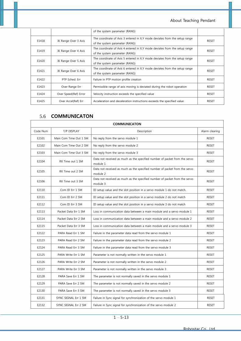
About Teaching Pendant
1 - 5-13
Robostar Co., Ltd
of the system parameter (RANG)
E1418 IK Range Over 3 Axis The coordinate of Axis 3 entered in X,Y mode deviates from the setup range
of the system parameter (RANG) RESET
E1419 IK Range Over 4 Axis The coordinate of Axis 4 entered in X,Y mode deviates from the setup range
of the system parameter (RANG) RESET
E1420 IK Range Over 5 Axis The coordinate of Axis 5 entered in X,Y mode deviates from the setup range
of the system parameter (RANG) RESET
E1421 IK Range Over 6 Axis The coordinate of Axis 6 entered in X,Y mode deviates from the setup range
of the system parameter (RANG) RESET
E1422 PTP Sched. Err Failure in PTP motion profile creation RESET
E1423 Over Range Err Permissible range of axis moving is deviated during the robot operation RESET
E1424 Over Speed(Ref) Error Velocity instruction exceeds the specified value RESET
E1425 Over Accel(Ref) Err Acceleration and deceleration instructions exceeds the specified value RESET
5.6 COMMUNICATON
COMMUNICATON
Code Num T/P DISPLAY Description Alarm clearing
E2101 Main Com Time Out 1 SM No reply from the servo module 1 RESET
E2102 Main Com Time Out 2 SM No reply from the servo module 2 RESET
E2103 Main Com Time Out 3 SM No reply from the servo module 3 RESET
E2104 RX Time out 1 SM Data not received as much as the specified number of packet from the servo
module 1 RESET
E2105 RX Time out 2 SM Data not received as much as the specified number of packet from the servo
module 2 RESET
E2106 RX Time out 3 SM Data not received as much as the specified number of packet from the servo
module 3 RESET
E2110 Com ID Err 1 SM ID setup value and the slot position in a servo module 1 do not match. RESET
E2111 Com ID Err 2 SM ID setup value and the slot position in a servo module 2 do not match RESET
E2112 Com ID Err 3 SM ID setup value and the slot position in a servo module 3 do not match RESET
E2113 Packet Data Err 1 SM Loss in communication data between a main module and a servo module 1 RESET
E2114 Packet Data Err 2 SM Loss in communication data between a main module and a servo module 2 RESET
E2115 Packet Data Err 3 SM Loss in communication data between a main module and a servo module 3 RESET
E2122 PARA Read Err 1 SM Failure in the parameter data read from the servo module 1 RESET
E2123 PARA Read Err 2 SM Failure in the parameter data read from the servo module 2 RESET
E2124 PARA Read Err 3 SM Failure in the parameter data read from the servo module 3 RESET
E2125 PARA Write Err 1 SM Parameter is not normally written in the servo module 1 RESET
E2126 PARA Write Err 2 SM Parameter is not normally written in the servo module 2 RESET
E2127 PARA Write Err 3 SM Parameter is not normally written in the servo module 3 RESET
E2128 PARA Save Err 1 SM The parameter is not normally saved in the servo module 1 RESET
E2129 PARA Save Err 2 SM The parameter is not normally saved in the servo module 2 RESET
E2130 PARA Save Err 3 SM The parameter is not normally saved in the servo module 3 RESET
E2131 SYNC SIGNAL Err 1 SM Failure in Sync signal for synchronization of the servo module 1 RESET
E2132 SYNC SIGNAL Err 2 SM Failure in Sync signal for synchronization of the servo module 2 RESET
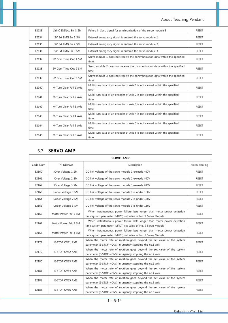
About Teaching Pendant
1 - 5-14
Robostar Co., Ltd
E2133 SYNC SIGNAL Err 3 SM Failure in Sync signal for synchronization of the servo module 3 RESET
E2134 SV Ext EMG Err 1 SM External emergency signal is entered the servo module 1 RESET
E2135 SV Ext EMG Err 2 SM External emergency signal is entered the servo module 2 RESET
E2136 SV Ext EMG Err 3 SM External emergency signal is entered the servo module 3 RESET
E2137 SV Com Time Out 1 SM Servo module 1 does not receive the communication data within the specified
time RESET
E2138 SV Com Time Out 2 SM Servo module 2 does not receive the communication data within the specified
time RESET
E2139 SV Com Time Out 3 SM Servo module 3 does not receive the communication data within the specified
time RESET
E2140 M-Turn Clear Fail 1 Axis Multi-turn data of an encoder of Axis 1 is not cleared within the specified
time RESET
E2141 M-Turn Clear Fail 2 Axis Multi-turn data of an encoder of Axis 2 is not cleared within the specified
time RESET
E2142 M-Turn Clear Fail 3 Axis Multi-turn data of an encoder of Axis 3 is not cleared within the specified
time RESET
E2143 M-Turn Clear Fail 4 Axis Multi-turn data of an encoder of Axis 4 is not cleared within the specified
time RESET
E2144 M-Turn Clear Fail 5 Axis Multi-turn data of an encoder of Axis 5 is not cleared within the specified
time RESET
E2145 M-Turn Clear Fail 6 Axis Multi-turn data of an encoder of Axis 6 is not cleared within the specified
time RESET
5.7 SERVO AMP
SERVO AMP
Code Num T/P DISPLAY Description Alarm clearing
E2160 Over Voltage 1 SM DC link voltage of the servo module 1 exceeds 400V RESET
E2161 Over Voltage 2 SM DC link voltage of the servo module 2 exceeds 400V RESET
E2162 Over Voltage 3 SM DC link voltage of the servo module 3 exceeds 400V RESET
E2163 Under Voltage 1 SM DC link voltage of the servo module 1 is under 180V RESET
E2164 Under Voltage 2 SM DC link voltage of the servo module 2 is under 180V RESET
E2165 Under Voltage 3 SM DC link voltage of the servo module 3 is under 180V RESET
E2166 Motor Power Fail 1 SM When instantaneous power failure lasts longer than motor power detection
time system parameter (MPDT) set value of No. 1 Servo Module RESET
E2167 Motor Power Fail 2 SM When instantaneous power failure lasts longer than motor power detection
time system parameter (MPDT) set value of No. 2 Servo Module RESET
E2168 Motor Power Fail 3 SM When instantaneous power failure lasts longer than motor power detection
time system parameter (MPDT) set value of No. 3 Servo Module RESET
E2178 E-STOP OVS1 AXIS When the motor rate of rotation goes beyond the set value of the system
parameter (E-STOP->OVS) in urgently stopping the no.1 axis RESET
E2179 E-STOP OVS2 AXIS When the motor rate of rotation goes beyond the set value of the system
parameter (E-STOP->OVS) in urgently stopping the no.2 axis RESET
E2180 E-STOP OVS3 AXIS When the motor rate of rotation goes beyond the set value of the system
parameter (E-STOP->OVS) in urgently stopping the no.3 axis RESET
E2181 E-STOP OVS4 AXIS When the motor rate of rotation goes beyond the set value of the system
parameter (E-STOP->OVS) in urgently stopping the no.4 axis RESET
E2182 E-STOP OVS5 AXIS When the motor rate of rotation goes beyond the set value of the system
parameter (E-STOP->OVS) in urgently stopping the no.5 axis RESET
E2183 E-STOP OVS6 AXIS When the motor rate of rotation goes beyond the set value of the system
parameter (E-STOP->OVS) in urgently stopping the no.6 axis RESET
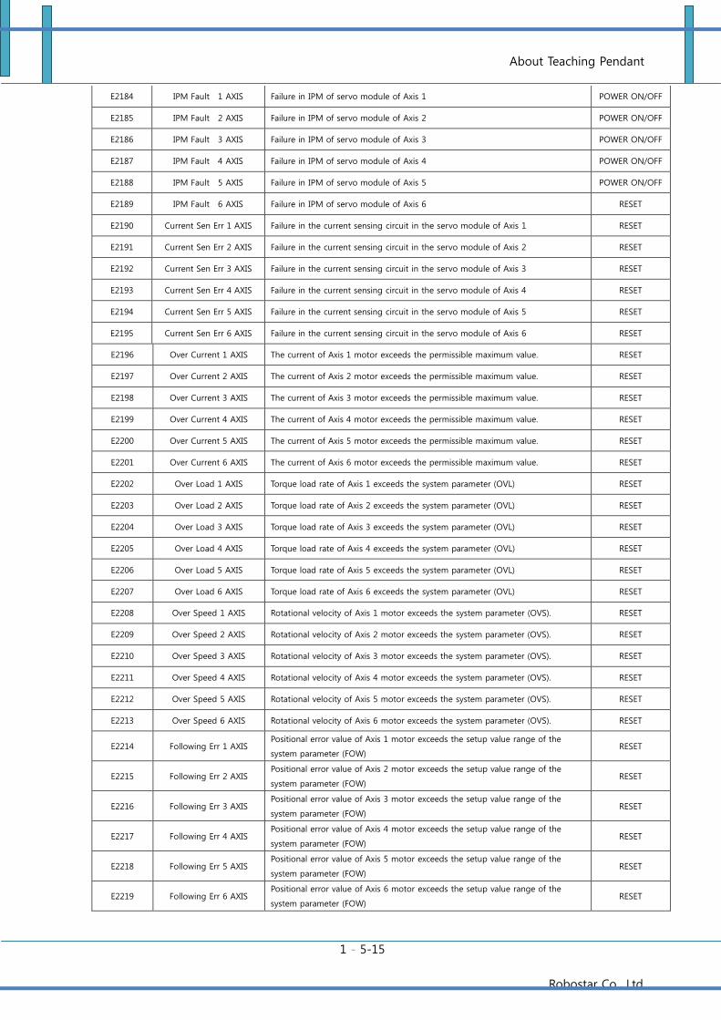
About Teaching Pendant
1 - 5-15
Robostar Co., Ltd
E2184 IPM Fault 1 AXIS Failure in IPM of servo module of Axis 1 POWER ON/OFF
E2185 IPM Fault 2 AXIS Failure in IPM of servo module of Axis 2 POWER ON/OFF
E2186 IPM Fault 3 AXIS Failure in IPM of servo module of Axis 3 POWER ON/OFF
E2187 IPM Fault 4 AXIS Failure in IPM of servo module of Axis 4 POWER ON/OFF
E2188 IPM Fault 5 AXIS Failure in IPM of servo module of Axis 5 POWER ON/OFF
E2189 IPM Fault 6 AXIS Failure in IPM of servo module of Axis 6 RESET
E2190 Current Sen Err 1 AXIS Failure in the current sensing circuit in the servo module of Axis 1 RESET
E2191 Current Sen Err 2 AXIS Failure in the current sensing circuit in the servo module of Axis 2 RESET
E2192 Current Sen Err 3 AXIS Failure in the current sensing circuit in the servo module of Axis 3 RESET
E2193 Current Sen Err 4 AXIS Failure in the current sensing circuit in the servo module of Axis 4 RESET
E2194 Current Sen Err 5 AXIS Failure in the current sensing circuit in the servo module of Axis 5 RESET
E2195 Current Sen Err 6 AXIS Failure in the current sensing circuit in the servo module of Axis 6 RESET
E2196 Over Current 1 AXIS The current of Axis 1 motor exceeds the permissible maximum value. RESET
E2197 Over Current 2 AXIS The current of Axis 2 motor exceeds the permissible maximum value. RESET
E2198 Over Current 3 AXIS The current of Axis 3 motor exceeds the permissible maximum value. RESET
E2199 Over Current 4 AXIS The current of Axis 4 motor exceeds the permissible maximum value. RESET
E2200 Over Current 5 AXIS The current of Axis 5 motor exceeds the permissible maximum value. RESET
E2201 Over Current 6 AXIS The current of Axis 6 motor exceeds the permissible maximum value. RESET
E2202 Over Load 1 AXIS Torque load rate of Axis 1 exceeds the system parameter (OVL) RESET
E2203 Over Load 2 AXIS Torque load rate of Axis 2 exceeds the system parameter (OVL) RESET
E2204 Over Load 3 AXIS Torque load rate of Axis 3 exceeds the system parameter (OVL) RESET
E2205 Over Load 4 AXIS Torque load rate of Axis 4 exceeds the system parameter (OVL) RESET
E2206 Over Load 5 AXIS Torque load rate of Axis 5 exceeds the system parameter (OVL) RESET
E2207 Over Load 6 AXIS Torque load rate of Axis 6 exceeds the system parameter (OVL) RESET
E2208 Over Speed 1 AXIS Rotational velocity of Axis 1 motor exceeds the system parameter (OVS). RESET
E2209 Over Speed 2 AXIS Rotational velocity of Axis 2 motor exceeds the system parameter (OVS). RESET
E2210 Over Speed 3 AXIS Rotational velocity of Axis 3 motor exceeds the system parameter (OVS). RESET
E2211 Over Speed 4 AXIS Rotational velocity of Axis 4 motor exceeds the system parameter (OVS). RESET
E2212 Over Speed 5 AXIS Rotational velocity of Axis 5 motor exceeds the system parameter (OVS). RESET
E2213 Over Speed 6 AXIS Rotational velocity of Axis 6 motor exceeds the system parameter (OVS). RESET
E2214 Following Err 1 AXIS Positional error value of Axis 1 motor exceeds the setup value range of the
system parameter (FOW) RESET
E2215 Following Err 2 AXIS Positional error value of Axis 2 motor exceeds the setup value range of the
system parameter (FOW) RESET
E2216 Following Err 3 AXIS Positional error value of Axis 3 motor exceeds the setup value range of the
system parameter (FOW) RESET
E2217 Following Err 4 AXIS Positional error value of Axis 4 motor exceeds the setup value range of the
system parameter (FOW) RESET
E2218 Following Err 5 AXIS Positional error value of Axis 5 motor exceeds the setup value range of the
system parameter (FOW) RESET
E2219 Following Err 6 AXIS Positional error value of Axis 6 motor exceeds the setup value range of the
system parameter (FOW) RESET
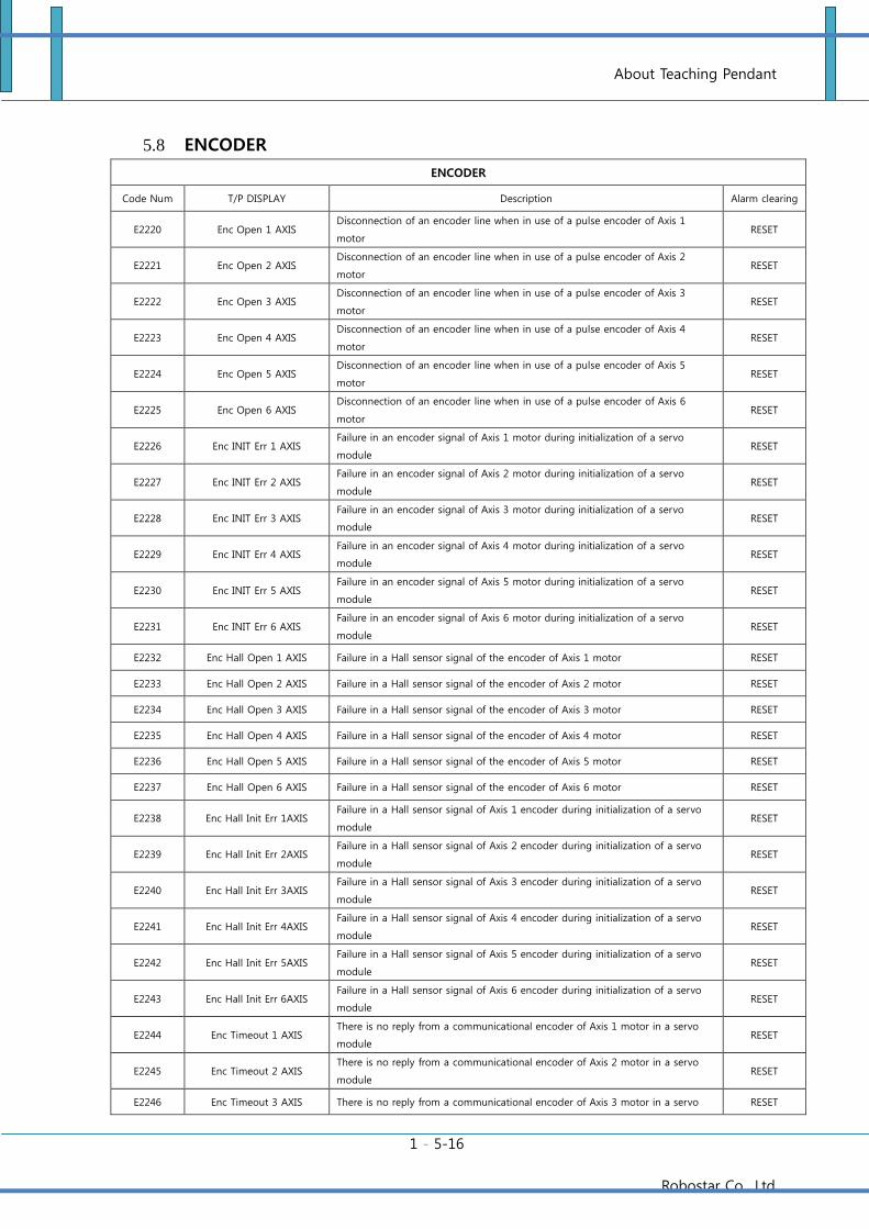
About Teaching Pendant
1 - 5-16
Robostar Co., Ltd
5.8 ENCODER
ENCODER
Code Num T/P DISPLAY Description Alarm clearing
E2220 Enc Open 1 AXIS Disconnection of an encoder line when in use of a pulse encoder of Axis 1
motor RESET
E2221 Enc Open 2 AXIS Disconnection of an encoder line when in use of a pulse encoder of Axis 2
motor RESET
E2222 Enc Open 3 AXIS Disconnection of an encoder line when in use of a pulse encoder of Axis 3
motor RESET
E2223 Enc Open 4 AXIS Disconnection of an encoder line when in use of a pulse encoder of Axis 4
motor RESET
E2224 Enc Open 5 AXIS Disconnection of an encoder line when in use of a pulse encoder of Axis 5
motor RESET
E2225 Enc Open 6 AXIS Disconnection of an encoder line when in use of a pulse encoder of Axis 6
motor RESET
E2226 Enc INIT Err 1 AXIS Failure in an encoder signal of Axis 1 motor during initialization of a servo
module RESET
E2227 Enc INIT Err 2 AXIS Failure in an encoder signal of Axis 2 motor during initialization of a servo
module RESET
E2228 Enc INIT Err 3 AXIS Failure in an encoder signal of Axis 3 motor during initialization of a servo
module RESET
E2229 Enc INIT Err 4 AXIS Failure in an encoder signal of Axis 4 motor during initialization of a servo
module RESET
E2230 Enc INIT Err 5 AXIS Failure in an encoder signal of Axis 5 motor during initialization of a servo
module RESET
E2231 Enc INIT Err 6 AXIS Failure in an encoder signal of Axis 6 motor during initialization of a servo
module RESET
E2232 Enc Hall Open 1 AXIS Failure in a Hall sensor signal of the encoder of Axis 1 motor RESET
E2233 Enc Hall Open 2 AXIS Failure in a Hall sensor signal of the encoder of Axis 2 motor RESET
E2234 Enc Hall Open 3 AXIS Failure in a Hall sensor signal of the encoder of Axis 3 motor RESET
E2235 Enc Hall Open 4 AXIS Failure in a Hall sensor signal of the encoder of Axis 4 motor RESET
E2236 Enc Hall Open 5 AXIS Failure in a Hall sensor signal of the encoder of Axis 5 motor RESET
E2237 Enc Hall Open 6 AXIS Failure in a Hall sensor signal of the encoder of Axis 6 motor RESET
E2238 Enc Hall Init Err 1AXIS Failure in a Hall sensor signal of Axis 1 encoder during initialization of a servo
module RESET
E2239 Enc Hall Init Err 2AXIS Failure in a Hall sensor signal of Axis 2 encoder during initialization of a servo
module RESET
E2240 Enc Hall Init Err 3AXIS Failure in a Hall sensor signal of Axis 3 encoder during initialization of a servo
module RESET
E2241 Enc Hall Init Err 4AXIS Failure in a Hall sensor signal of Axis 4 encoder during initialization of a servo
module RESET
E2242 Enc Hall Init Err 5AXIS Failure in a Hall sensor signal of Axis 5 encoder during initialization of a servo
module RESET
E2243 Enc Hall Init Err 6AXIS Failure in a Hall sensor signal of Axis 6 encoder during initialization of a servo
module RESET
E2244 Enc Timeout 1 AXIS There is no reply from a communicational encoder of Axis 1 motor in a servo
module RESET
E2245 Enc Timeout 2 AXIS There is no reply from a communicational encoder of Axis 2 motor in a servo
module RESET
E2246 Enc Timeout 3 AXIS There is no reply from a communicational encoder of Axis 3 motor in a servo RESET
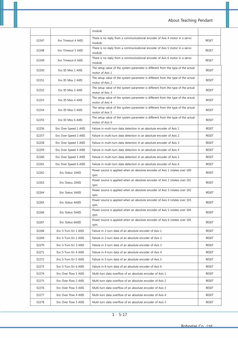
About Teaching Pendant
1 - 5-17
Robostar Co., Ltd
module
E2247 Enc Timeout 4 AXIS There is no reply from a communicational encoder of Axis 4 motor in a servo
module RESET
E2248 Enc Timeout 5 AXIS There is no reply from a communicational encoder of Axis 5 motor in a servo
module RESET
E2249 Enc Timeout 6 AXIS There is no reply from a communicational encoder of Axis 6 motor in a servo
module RESET
E2250 Enc ID Miss 1 AXIS The setup value of the system parameter is different from the type of the actual
motor of Axis 1 RESET
E2251 Enc ID Miss 2 AXIS The setup value of the system parameter is different from the type of the actual
motor of Axis 2 RESET
E2252 Enc ID Miss 3 AXIS The setup value of the system parameter is different from the type of the actual
motor of Axis 3 RESET
E2253 Enc ID Miss 4 AXIS The setup value of the system parameter is different from the type of the actual
motor of Axis 4 RESET
E2254 Enc ID Miss 5 AXIS The setup value of the system parameter is different from the type of the actual
motor of Axis 5 RESET
E2255 Enc ID Miss 6 AXIS The setup value of the system parameter is different from the type of the actual
motor of Axis 6 RESET
E2256 Enc Over Speed 1 AXIS Failure in multi-turn data detection in an absolute encoder of Axis 1 RESET
E2257 Enc Over Speed 2 AXIS Failure in multi-turn data detection in an absolute encoder of Axis 2 RESET
E2258 Enc Over Speed 3 AXIS Failure in multi-turn data detection in an absolute encoder of Axis 3 RESET
E2259 Enc Over Speed 4 AXIS Failure in multi-turn data detection in an absolute encoder of Axis 4 RESET
E2260 Enc Over Speed 5 AXIS Failure in multi-turn data detection in an absolute encoder of Axis 5 RESET
E2261 Enc Over Speed 6 AXIS Failure in multi-turn data detection in an absolute encoder of Axis 6 RESET
E2262 Enc Status 1AXIS Power source is applied when an absolute encoder of Axis 1 rotates over 100
rpm. RESET
E2263 Enc Status 2AXIS Power source is applied when an absolute encoder of Axis 2 rotates over 101
rpm. RESET
E2264 Enc Status 3AXIS Power source is applied when an absolute encoder of Axis 3 rotates over 102
rpm. RESET
E2265 Enc Status 4AXIS Power source is applied when an absolute encoder of Axis 4 rotates over 103
rpm. RESET
E2266 Enc Status 5AXIS Power source is applied when an absolute encoder of Axis 5 rotates over 104
rpm. RESET
E2267 Enc Status 6AXIS Power source is applied when an absolute encoder of Axis 6 rotates over 105
rpm. RESET
E2268 Enc S-Turn Err 1 AXIS Failure in 1-turn data of an absolute encoder of Axis 1 RESET
E2269 Enc S-Turn Err 2 AXIS Failure in 2-turn data of an absolute encoder of Axis 2 RESET
E2270 Enc S-Turn Err 3 AXIS Failure in 3-turn data of an absolute encoder of Axis 3 RESET
E2271 Enc S-Turn Err 4 AXIS Failure in 4-turn data of an absolute encoder of Axis 4 RESET
E2272 Enc S-Turn Err 5 AXIS Failure in 5-turn data of an absolute encoder of Axis 5 RESET
E2273 Enc S-Turn Err 6 AXIS Failure in 6-turn data of an absolute encoder of Axis 6 RESET
E2274 Enc Over Flow 1 AXIS Multi-turn data overflow of an absolute encoder of Axis 1 RESET
E2275 Enc Over Flow 2 AXIS Multi-turn data overflow of an absolute encoder of Axis 2 RESET
E2276 Enc Over Flow 3 AXIS Multi-turn data overflow of an absolute encoder of Axis 3 RESET
E2277 Enc Over Flow 4 AXIS Multi-turn data overflow of an absolute encoder of Axis 4 RESET
E2278 Enc Over Flow 5 AXIS Multi-turn data overflow of an absolute encoder of Axis 5 RESET
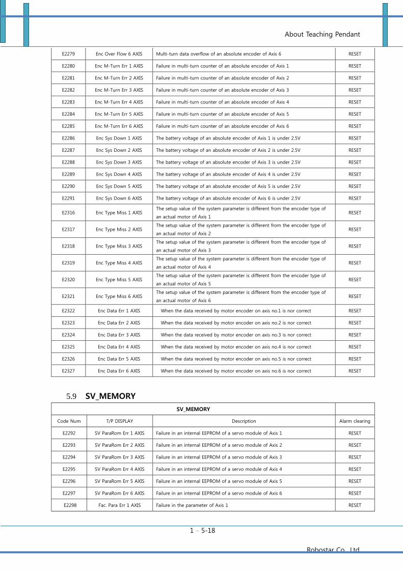
About Teaching Pendant
1 - 5-18
Robostar Co., Ltd
E2279 Enc Over Flow 6 AXIS Multi-turn data overflow of an absolute encoder of Axis 6 RESET
E2280 Enc M-Turn Err 1 AXIS Failure in multi-turn counter of an absolute encoder of Axis 1 RESET
E2281 Enc M-Turn Err 2 AXIS Failure in multi-turn counter of an absolute encoder of Axis 2 RESET
E2282 Enc M-Turn Err 3 AXIS Failure in multi-turn counter of an absolute encoder of Axis 3 RESET
E2283 Enc M-Turn Err 4 AXIS Failure in multi-turn counter of an absolute encoder of Axis 4 RESET
E2284 Enc M-Turn Err 5 AXIS Failure in multi-turn counter of an absolute encoder of Axis 5 RESET
E2285 Enc M-Turn Err 6 AXIS Failure in multi-turn counter of an absolute encoder of Axis 6 RESET
E2286 Enc Sys Down 1 AXIS The battery voltage of an absolute encoder of Axis 1 is under 2.5V RESET
E2287 Enc Sys Down 2 AXIS The battery voltage of an absolute encoder of Axis 2 is under 2.5V RESET
E2288 Enc Sys Down 3 AXIS The battery voltage of an absolute encoder of Axis 3 is under 2.5V RESET
E2289 Enc Sys Down 4 AXIS The battery voltage of an absolute encoder of Axis 4 is under 2.5V RESET
E2290 Enc Sys Down 5 AXIS The battery voltage of an absolute encoder of Axis 5 is under 2.5V RESET
E2291 Enc Sys Down 6 AXIS The battery voltage of an absolute encoder of Axis 6 is under 2.5V RESET
E2316 Enc Type Miss 1 AXIS The setup value of the system parameter is different from the encoder type of
an actual motor of Axis 1 RESET
E2317 Enc Type Miss 2 AXIS The setup value of the system parameter is different from the encoder type of
an actual motor of Axis 2 RESET
E2318 Enc Type Miss 3 AXIS The setup value of the system parameter is different from the encoder type of
an actual motor of Axis 3 RESET
E2319 Enc Type Miss 4 AXIS The setup value of the system parameter is different from the encoder type of
an actual motor of Axis 4 RESET
E2320 Enc Type Miss 5 AXIS The setup value of the system parameter is different from the encoder type of
an actual motor of Axis 5 RESET
E2321 Enc Type Miss 6 AXIS The setup value of the system parameter is different from the encoder type of
an actual motor of Axis 6 RESET
E2322 Enc Data Err 1 AXIS When the data received by motor encoder on axis no.1 is nor correct RESET
E2323 Enc Data Err 2 AXIS When the data received by motor encoder on axis no.2 is nor correct RESET
E2324 Enc Data Err 3 AXIS When the data received by motor encoder on axis no.3 is nor correct RESET
E2325 Enc Data Err 4 AXIS When the data received by motor encoder on axis no.4 is nor correct RESET
E2326 Enc Data Err 5 AXIS When the data received by motor encoder on axis no.5 is nor correct RESET
E2327 Enc Data Err 6 AXIS When the data received by motor encoder on axis no.6 is nor correct RESET
5.9 SV_MEMORY
SV_MEMORY
Code Num T/P DISPLAY Description Alarm clearing
E2292 SV ParaRom Err 1 AXIS Failure in an internal EEPROM of a servo module of Axis 1 RESET
E2293 SV ParaRom Err 2 AXIS Failure in an internal EEPROM of a servo module of Axis 2 RESET
E2294 SV ParaRom Err 3 AXIS Failure in an internal EEPROM of a servo module of Axis 3 RESET
E2295 SV ParaRom Err 4 AXIS Failure in an internal EEPROM of a servo module of Axis 4 RESET
E2296 SV ParaRom Err 5 AXIS Failure in an internal EEPROM of a servo module of Axis 5 RESET
E2297 SV ParaRom Err 6 AXIS Failure in an internal EEPROM of a servo module of Axis 6 RESET
E2298 Fac. Para Err 1 AXIS Failure in the parameter of Axis 1 RESET
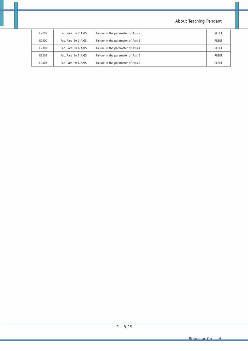
About Teaching Pendant
1 - 5-19
Robostar Co., Ltd
E2299 Fac. Para Err 2 AXIS Failure in the parameter of Axis 2 RESET
E2300 Fac. Para Err 3 AXIS Failure in the parameter of Axis 3 RESET
E2301 Fac. Para Err 4 AXIS Failure in the parameter of Axis 4 RESET
E2302 Fac. Para Err 5 AXIS Failure in the parameter of Axis 5 RESET
E2303 Fac. Para Err 6 AXIS Failure in the parameter of Axis 6 RESET
Robostar Co., Ltd.
Rev. Revised
Date Description Revisor
S/W
Version
V.1 2012.07.30 First Edition Printed Hong
V.2 2013.02.25 4-axis Controller integrated 6-axis Hong
N1 ROBOT CONTROLLER
CONTROLLER MANUAL
FIRST EDITION JULY 2012
ROBOSTAR CO., LTD.
ROBOT R&D CENTER
Related Documents