6/18/2015 1 Innovative Solutions for tomorrow’s transportation needs Roadside Safety: High Tension Cable Barrier Derwood Sheppard, P.E. Innovative Solutions for tomorrow’s transportation needs FDOT Roadside Safety Updates • February 26, 2015 - Moratorium on HTCB Lifted: Created Dev. Design Standards Index D450. Created Instructions Dev. for Design Standards, IDDS 450 Revised Dev. Specification 540. • Future Plans: MASH Implementation PPM Chapter 4 Redevelopment (In-Progress) Index 400, Guardrail - Redevelopment (In-Progress) Specification rewrite New IDS Index 410, Concrete Barrier Wall (Fall 2015) Others to Follow…

Welcome message from author
This document is posted to help you gain knowledge. Please leave a comment to let me know what you think about it! Share it to your friends and learn new things together.
Transcript
6/18/2015
1
Innovative Solutions for tomorrow’s transportation needs
Roadside Safety:
High Tension Cable BarrierDerwood Sheppard, P.E.
Innovative Solutions for tomorrow’s transportation needs
FDOT Roadside Safety Updates• February 26, 2015 - Moratorium on HTCB Lifted:
Created Dev. Design Standards Index D450. Created Instructions Dev. for Design Standards, IDDS 450 Revised Dev. Specification 540.
• Future Plans: MASH Implementation PPM Chapter 4 Redevelopment (In-Progress) Index 400, Guardrail - Redevelopment (In-Progress)
Specification rewrite New IDS
Index 410, Concrete Barrier Wall (Fall 2015) Others to Follow…

6/18/2015
2
Innovative Solutions for tomorrow’s transportation needs
High Tension Cable Barrier (HTCB)
Innovative Solutions for tomorrow’s transportation needs
HTCB Overview:• Primary Function – Reduce Median Crossover Crashes or
shield continuous longitudinal roadside hazards (e.g. canal hazards).
• Additional Barrier Option to PPM, Vol. 1, Chapter 4.• Flexible Barrier System = greater deflections than guardrail
(semi-rigid) or concrete barriers (rigid).
• Flexibility allows system to absorb and distribute more impact energy while effectively containing and redirecting vehicles.
• Require Larger Lateral Offsets/Setbacks to provide deflection space.
• Objective – Reduce Crossover A+K Collisions without Increasing Crash Severity.
6/18/2015
3
Innovative Solutions for tomorrow’s transportation needs
Innovative Solutions for tomorrow’s transportation needs
HTCB Updates• Remains a “Developmental” Process
• New Developmental Design Standard (DDS) Index 450
• New Instructions for Dev. Design Standards (IDDS)
• Revised Developmental Specification Dev540 Cable Heights Specified per NCHRP Report 711
Shop Drawing Requirements
Design Criteria
End Terminal Foundations
Line Post Foundations
Mow Strip
Basis of Payment
• New Innovative Products List (IPL)
6/18/2015
4
Innovative Solutions for tomorrow’s transportation needs
Developmental Standards & Specifications
!!!*** IMPORTANT ***!!!
“Developmental” Means Standards and Specifications Can Change Throughout the Process.
Always refer to Specification and Standards included in the Contract Documents!
Review Latest Information Posted on the FDOT Website.
Innovative Solutions for tomorrow’s transportation needs
FDOT Developmental Information

6/18/2015
5
Innovative Solutions for tomorrow’s transportation needs
FDOT Developmental Information
Innovative Solutions for tomorrow’s transportation needs
DDS Index D450

6/18/2015
6
Innovative Solutions for tomorrow’s transportation needs
DDS Index D450
Innovative Solutions for tomorrow’s transportation needs
Instructions for Developmental Design Standards (IDDS) Index D450
IDDS Includes the following:Design Assumptions and Limitations
Selection & Placement Guidelines
Plan Content Requirements
Payment
6/18/2015
7
Innovative Solutions for tomorrow’s transportation needs
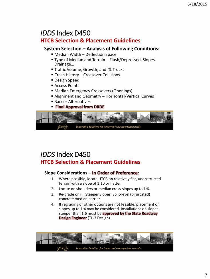
IDDS Index D450HTCB Selection & Placement Guidelines
System Selection – Analysis of Following Conditions: Median Width – Deflection Space Type of Median and Terrain – Flush/Depressed, Slopes,
Drainage… Traffic Volume, Growth, and % Trucks Crash History – Crossover Collisions Design Speed Access Points Median Emergency Crossovers (Openings) Alignment and Geometry – Horizontal/Vertical Curves Barrier Alternatives Final Approval from DRDE
Innovative Solutions for tomorrow’s transportation needs
IDDS Index D450HTCB Selection & Placement Guidelines
Slope Considerations – In Order of Preference:1. Where possible, locate HTCB on relatively flat, unobstructed
terrain with a slope of 1:10 or flatter.
2. Locate on shoulders or median cross-slopes up to 1:6.
3. Re-grade or Fill Steeper Slopes. Split-level (bifurcated) concrete median barrier.
4. If regrading or other options are not feasible, placement on slopes up to 1:4 may be considered. Installations on slopes steeper than 1:6 must be approved by the State Roadway Design Engineer (TL-3 Design).

6/18/2015
8
Innovative Solutions for tomorrow’s transportation needs
IDDS Index D450HTCB Selection & Placement Guidelines
Length of Need (LON) Considerations: Generally Based on Reducing Median Crossovers
Minimum Length Preferred – 1,000 feet
Absolute – 300 feet
Maximum – Varies based on Site Constraints (>10,000 ft)
Median Crossovers (Openings)
Departure Line in Accordance with Index 400, Guardrail
Innovative Solutions for tomorrow’s transportation needs
IDDS Index D450HTCB Selection & Placement Guidelines
Lateral Placement: (NCHRP Report 711) As far from traffic as possible
Allows for ample Deflection Space
Reduces nuisance impacts
Avoid – Ditch Bottoms, Toe of Slopes, & Drainage Features
Slopes 1:6 or Flatter follow HTCB Lateral Offset limits shown on Index D450.
6/18/2015
9
Innovative Solutions for tomorrow’s transportation needs
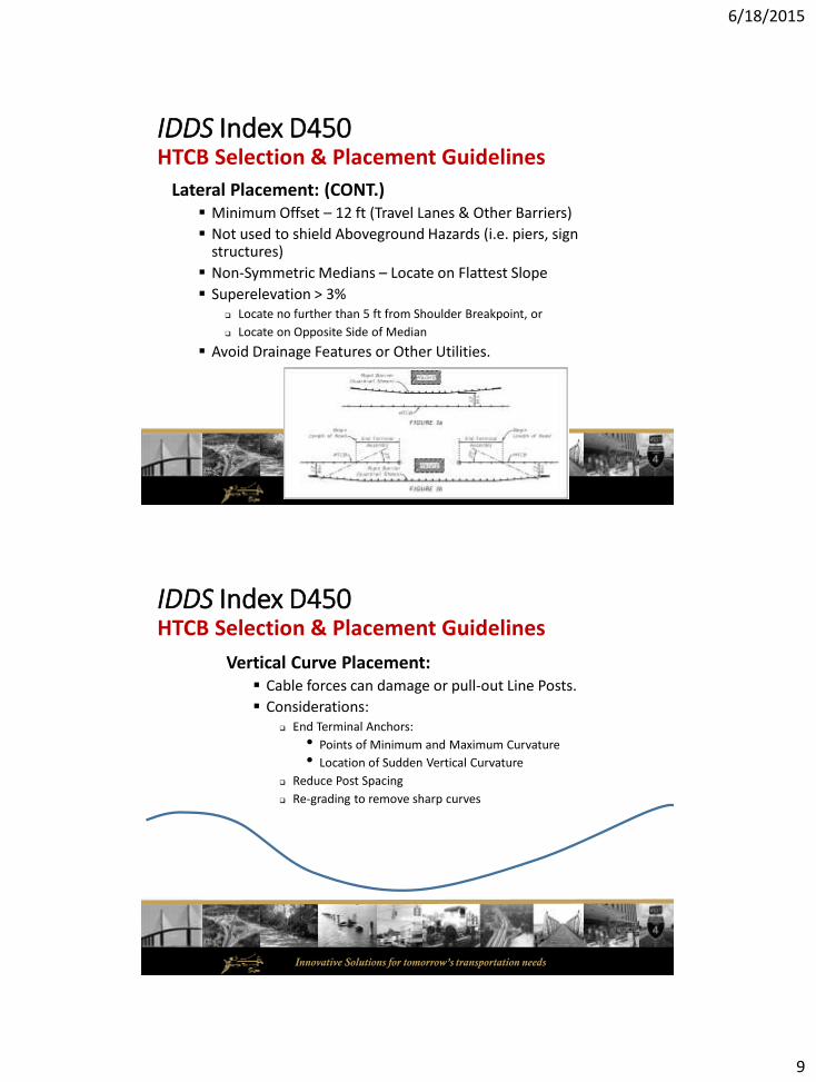
IDDS Index D450HTCB Selection & Placement Guidelines
Lateral Placement: (CONT.) Minimum Offset – 12 ft (Travel Lanes & Other Barriers)
Not used to shield Aboveground Hazards (i.e. piers, sign structures)
Non-Symmetric Medians – Locate on Flattest Slope
Superelevation > 3% Locate no further than 5 ft from Shoulder Breakpoint, or
Locate on Opposite Side of Median
Avoid Drainage Features or Other Utilities.
Innovative Solutions for tomorrow’s transportation needs
IDDS Index D450HTCB Selection & Placement Guidelines
Vertical Curve Placement: Cable forces can damage or pull-out Line Posts.
Considerations: End Terminal Anchors:
• Points of Minimum and Maximum Curvature
• Location of Sudden Vertical Curvature
Reduce Post Spacing
Re-grading to remove sharp curves
6/18/2015
10
Innovative Solutions for tomorrow’s transportation needs
IDDS Index D450HTCB Selection & Placement Guidelines
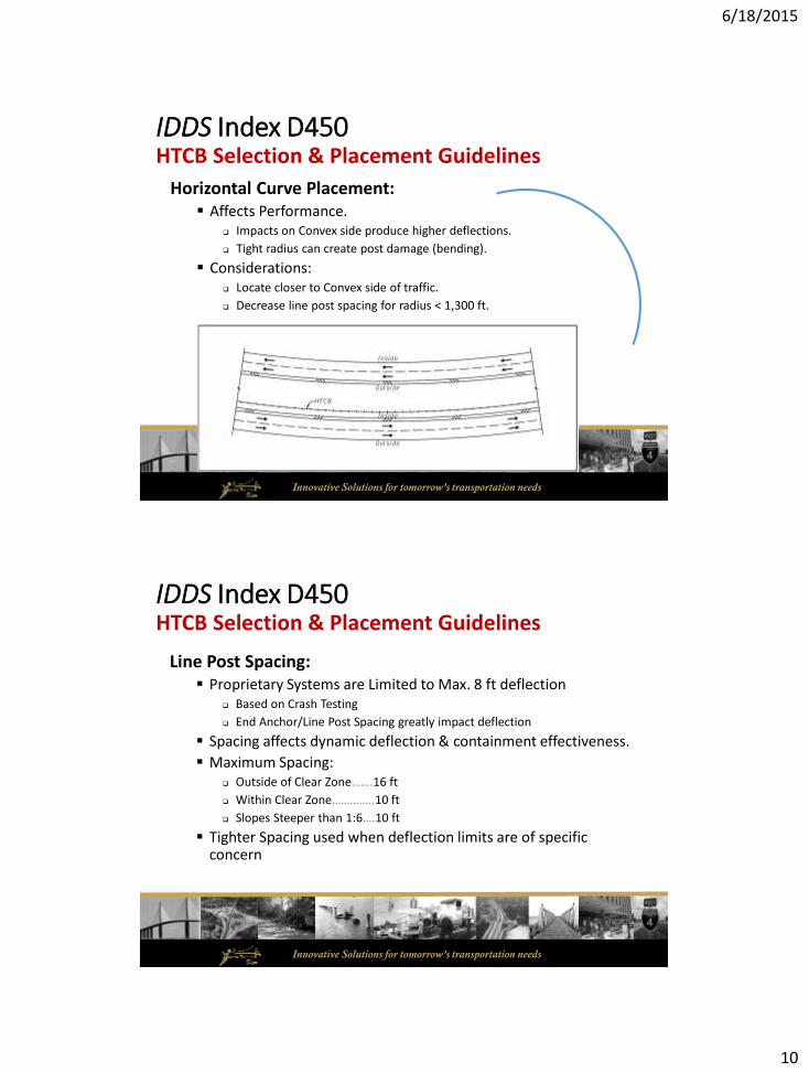
Horizontal Curve Placement: Affects Performance.
Impacts on Convex side produce higher deflections.
Tight radius can create post damage (bending).
Considerations: Locate closer to Convex side of traffic.
Decrease line post spacing for radius < 1,300 ft.
Innovative Solutions for tomorrow’s transportation needs
IDDS Index D450HTCB Selection & Placement Guidelines
Line Post Spacing: Proprietary Systems are Limited to Max. 8 ft deflection
Based on Crash Testing
End Anchor/Line Post Spacing greatly impact deflection
Spacing affects dynamic deflection & containment effectiveness.
Maximum Spacing: Outside of Clear Zone…….16 ft
Within Clear Zone…………..10 ft
Slopes Steeper than 1:6….10 ft
Tighter Spacing used when deflection limits are of specific concern

6/18/2015
11
Innovative Solutions for tomorrow’s transportation needs
IDDS Index D450HTCB Selection & Placement Guidelines
End Terminal Placement & Protection: Variable Length End Treatments
Limits on IPL may been needed for LON.
When Possible, Protect End Treatments with adjacent Barriers End Treatments are Crashworthy, BUT
“Gating” (i.e. Loss of Tension when hit).
Innovative Solutions for tomorrow’s transportation needs
IDDS Index D450HTCB Selection & Placement Guidelines
Barrier (End Terminal) Overlap – Protection of End Terminals:
Switching Side of Median Gradual Transitions from One Side to the Other is permitted
Do Not Taper HTCB towards the Direction of Traffic
System Limitations
Terrain Constraints (i.e. Vertical Curves)
Maximum Length Restrictions
6/18/2015
12
Innovative Solutions for tomorrow’s transportation needs
IDDS Index D450HTCB Selection & Placement Guidelines
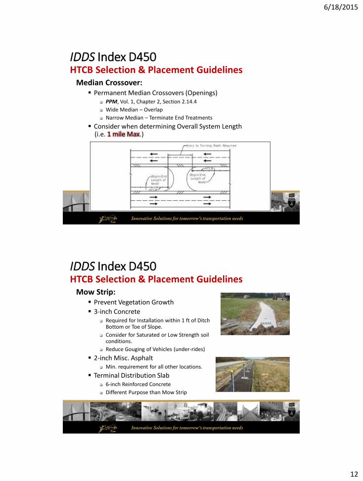
Median Crossover: Permanent Median Crossovers (Openings)
PPM, Vol. 1, Chapter 2, Section 2.14.4
Wide Median – Overlap
Narrow Median – Terminate End Treatments
Consider when determining Overall System Length (i.e. 1 mile Max.)
Innovative Solutions for tomorrow’s transportation needs
IDDS Index D450HTCB Selection & Placement Guidelines
Mow Strip: Prevent Vegetation Growth
3-inch Concrete Required for Installation within 1 ft of Ditch
Bottom or Toe of Slope.
Consider for Saturated or Low Strength soil conditions.
Reduce Gouging of Vehicles (under-rides)
2-inch Misc. Asphalt Min. requirement for all other locations.
Terminal Distribution Slab 6-inch Reinforced Concrete
Different Purpose than Mow Strip

6/18/2015
13
Innovative Solutions for tomorrow’s transportation needs
IDDS Index D450HTCB Selection & Placement Guidelines
Soil & Groundwater Conditions: SHGW Depth ≥ 1 ft (Below Grade)
Line Post Foundation Design: Saturated or Unsaturated
Classification = Cohesionless (Fine Sand)
Friction Angle = 30 Degrees
Moist Unit Weight = 112 lbs./cu. ft.
Effective Unit Weight = 50 lbs./cu. ft.
End Terminal Foundations – Design Data Tables
Evaluate in accordance with Soils and Foundations Handbook, Section 3.2.2.10
Foundations Designed by Specialty Engineer
Innovative Solutions for tomorrow’s transportation needs
IDDS Index D450Plan Content Requirements
DDS Index D450: Include Developmental Design Standards Index D450 in Plan Set Special Details section of Roadway Plans PPM, Vol. 2, Section 3.8
Typical Sections: Indicate lateral offset on the Roadway Typical Sections
Roadway Plan Views: Length of Need (LON)
Station and Offset
HTCB Run No.
Space Limitations (i.e. End Treatment Length), if any.
Line Post Spacing (if specific spacing required) Mow Strip (if specific type required)

6/18/2015
14
Innovative Solutions for tomorrow’s transportation needs
IDDS Index D450Plan Content Requirements
Special Details: Overlaps
Median Crossovers
Geotechnical: Report of Core Boring Sheets (End Anchorages)
Design Data Tables: Geotechnical Information:
End Terminal Foundations
Line Post Foundations
Summary of HTCB Locations and Foundations
Locations/Limits of Special Designs
Innovative Solutions for tomorrow’s transportation needs
IDDS Index D450Plan Content Requirements – Design Data Tables

6/18/2015
15
Innovative Solutions for tomorrow’s transportation needs
IDDS Index D450Plan Content Requirements
Innovative Solutions for tomorrow’s transportation needs
IDDS Index D450Payment
Basis of Payment (New Pay Item #’s):
End Terminal Foundation – per cubic yard
• Quantity in Plans for Bid Purposes Only
• Payment will be based on Shop Drawings

6/18/2015
16
Innovative Solutions for tomorrow’s transportation needs
IDDS Index D450Payment
Method of Measurement:
HTCB Length of Need Segment – per lineal foot
• Includes General HTCB segments only.
• End Terminals are separate.
Innovative Solutions for tomorrow’s transportation needs
IDDS Index D450Plan Content Requirements – Summary Table

6/18/2015
17
Innovative Solutions for tomorrow’s transportation needs
IDDS Index D450Payment
Summary Table:
Innovative Solutions for tomorrow’s transportation needs
Developmental Specification Dev540
6/18/2015
18
Innovative Solutions for tomorrow’s transportation needs
Developmental Specification Dev540
Innovative Solutions for tomorrow’s transportation needs
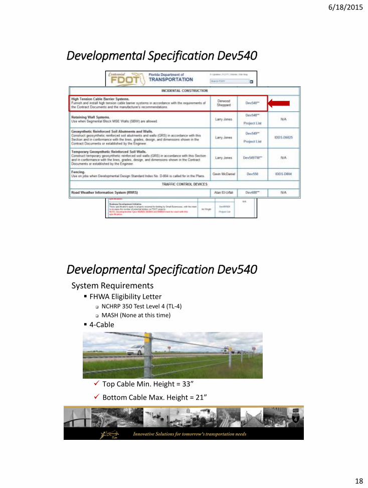
Developmental Specification Dev540System Requirements
FHWA Eligibility Letter NCHRP 350 Test Level 4 (TL-4)
MASH (None at this time)
4-Cable
Top Cable Min. Height = 33”
Bottom Cable Max. Height = 21”

6/18/2015
19
Innovative Solutions for tomorrow’s transportation needs
Developmental Specification Dev540
End Terminals Must be include in FHWA Eligibility Letter
Hardware same as in Crash Test
End Terminal Foundations ALL - Miscellaneous Structure Drilled Shaft
• Same Requirements as Mast Arms, High Mast Lights, Etc…
ALL - Project Specific Designed
Innovative Solutions for tomorrow’s transportation needs
End Terminal Foundations – Design Criteria
Design Loads – Thermal Loading Theoretical Cumulative Cable Tension @ Zero Degrees Fahrenheit
Lateral Deflection 1-inch Maximum Deflection
Developmental Specification Dev540
6/18/2015
20
Innovative Solutions for tomorrow’s transportation needs
Developmental Specification Dev540
Shop Drawings and Calculations Submittals
Shop Drawings:1. General notes and construction specifications
2. Height of each cable in the system
3. Post length and height of each post with respect to the ground level
4. Post Spacing along entire length of system
5. Detailed drawings of all posts and hardware
6. Turnbuckle and/or splice locations
7. Overall length of the cable barrier segment, including end terminals
8. Cable barrier length, excluding end terminals
9. End terminal design, including length and location (station/offset)
10.Foundation dimensions and detailed steel reinforcement layout for all concrete foundations, including end terminal anchors, end terminal transition line posts, and standard line posts
11.Location and design of Barrier Delineators, including line post and end terminal
Innovative Solutions for tomorrow’s transportation needs
Developmental Specification Dev540
Shop Drawings and Calculations Submittals
Design Calculations:1. The manufacturer’s product brochure, construction specifications, installation manual,
and maintenance manual
2. Contact information and qualifications/resume for manufacturer’s technical representative
3. Design tables including cable tension as a function of cable temperature
4. The NCHRP-350 or MASH FHWA eligibility letter for the proposed cable barrier system and end terminals
5. Blank sample of the proposed Cable Tension Log
6. The end terminal foundation design(s) prepared by the Contractor’s Specialty Engineer
7. The line post foundation design(s) prepared by the Contractor’s Specialty Engineer (required when geotechnical soil conditions do not meet standard criteria).
6/18/2015
21
Innovative Solutions for tomorrow’s transportation needs
Developmental Specification Dev540
Manufacturer’s Representative Onsite Milestones
1. Cable Barrier and Foundation Layout
2. Installation of End Terminal Cable Anchorage
3. Installation of Post Sleeves
4. Setting of Initial Line Post
5. Installation of Post Hardware
6. Cable Attachment and Tensioning
Installation TrainingManufacture must certify that Construction Personnel have received adequate training for installation and tensioning of system.
Innovative Solutions for tomorrow’s transportation needs
Developmental Specification Dev540
Cable Installation and Tensioning Cable Height Tolerance ± 1”
Location of Hardware As Crash Tested (FHWA Eligibility Letter)
Otherwise, DO NOT interfere with Line Post
Initial Tensioning
Final Tensioning 14 to 21 days after Initial Tensioning
Re-tensioning when < 90%
6/18/2015
22
Innovative Solutions for tomorrow’s transportation needs
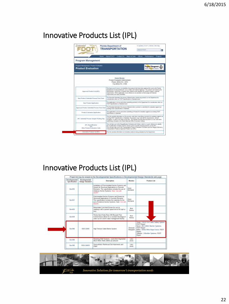
Innovative Products List (IPL)
Innovative Solutions for tomorrow’s transportation needs
Innovative Products List (IPL)

6/18/2015
23
Innovative Solutions for tomorrow’s transportation needs
Questions?
Related Documents