Welcome message from author
This document is posted to help you gain knowledge. Please leave a comment to let me know what you think about it! Share it to your friends and learn new things together.
Transcript

This guide was sponsored by the Federal Highway
Administration (FHWA), under FHWA Contract DTFH61-10-D-
00021, Roadside Safety Systems Installers and Designers
Mentor Program.
The following individuals prepared or reviewed this
document:
Project Team
William P. Longstreet - FHWA Safety Office COTM
Karen L. Boodlal - KLS Engineering, LLC
Richard D. Powers - KLS Engineering, LLC
John C. Durkos - KLS Engineering, LLC
TxDOT Representative
Rory Meza – Contract Lead
Chris Lindsey – Design Section
August 2014
(Updated Feb. 8, 2017)

Contents
Acronyms _____________________________________ iv
Glossary _______________________________________ v
Introduction ____________________________________ 1
Barrier Basics ___________________________________ 3
Barrier Guidelines: ____________________________________ 3
Establishing Barrier Guidelines __________________________ 3
Considerations _______________________________________ 4
Clear Zone ______________________________________ 4
Design Options (In order of preference) ___________________ 6
Roadside Obstacles ______________________________ 6
Roadside Slopes (Embankments) ________________________ 8
Barriers _____________________________________________ 9
Additional Design Considerations _______________________ 17
Design Deflection Distance ____________________________ 18
Height Measurement ___________________________ 18
Barrier Placement on Slopes ___________________________ 19
Guard fence and Curb ________________________________ 20
Guard fence and Trees ________________________________ 21
Connections to Bridge Barriers _________________________ 21
Guard fence at Intersections and Driveways _________ 24
Terminals and Crash Cushions ________________ 26
Terminals _____________________________________ 26
Types of Terminals _____________________________ 27
Terminal Grading Details ________________________ 31
Crash Cushions ________________________________ 32
Maintenance ______________________________ 41
Longitudinal Barrier Damage _____________________ 41
Repair/Upgrade/Remove ________________________ 55

Acronyms AASHTO American Association of State Highway and
Transportation Officials
ADT Average Daily Traffic
DOT Department of Transportation
EMS Emergency Medical Services
FHWA Federal Highway Administration
LR Length of Roadside Travel
LON Length of Need
MUTCD Manual on Uniform Traffic Control Devices
MASH Manual for Assessing Safety Hardware
NCHRP National Cooperative Highway Research
Program
RDG Roadside Design Guide
ROR Run off Road
TCP Traffic Control Plan
TL Test Level
TTC Temporary Traffic Control
TTCZ Temporary Traffic Control Zone
WZ Work Zone

Glossary Barricade—A device which provides a visual indicator of a
hazardous location or the desired path a motorist should
take. It is not intended to contain or redirect an errant
vehicle.
Barrier—A device which provides a physical limitation
through which a vehicle would not normally pass. It is
intended to contain or redirect an errant vehicle.
Breakaway—A design feature which allows a device such as a
sign, luminaire, or traffic signal support to yield or separate
upon impact The release mechanism may be a slip plane,
plastic hinges, fracture elements, or a combination of these.
Bridge Railing—A longitudinal barrier whose primary function
is to prevent an errant vehicle from going over the side of the
bridge structure.
Clearance—Lateral distance from edge of traveled way to a
roadside object or feature.
Clear Zone—The unobstructed, traversable area provided beyond the edge of the through traveled way for the recovery of errant vehicles. The clear zone includes shoulders, bike lanes, and auxiliary lanes, except those auxiliary lanes that function like through lanes. Cost-effective—An item or action taken that is economical in
terms of tangible benefits produced for the money spent.
Crash Cushion—Device that prevents an errant vehicle from
impacting a fixed object by gradually decelerating the vehicle
to a safe stop or by redirecting the vehicle away from the
obstacle.
Crash Tests—vehicular impact tests by which the structural
and safety performance of roadside barriers and other

highway appearances may be determined. Three evaluation
criteria are considered, namely (1) structural adequacy, (2)
impact severity, and (3) vehicular post-impact trajectory.
Crashworthy—A feature that has been proven acceptable for
use under specified conditions either through crash testing or
in-service performance.
Design Speed—A selected speed used to determine the
various geometric design features of the roadway. The
assumed design speed should be a logical one with respect to
the topography, anticipated operating speed, the adjacent
land use, and the functional classification of the highway.
Drainage Feature—Roadside items whose primary purpose is
to provide adequate roadway drainage such as curbs,
culverts, ditches, and drop inlets.
End Treatment—The designed modification of the end of a
roadside or median barrier.
Flare—The variable offset distance of a barrier to move it
farther from the traveled way; generally in reference to the
upstream end of the barrier.
Hinge—The weakened section of a sign post designed to
allow the post to rotate upward when impacted by a vehicle.
Impact Angle—For a longitudinal barrier, it is the angle
between a tangent to the face of the barrier and tangent to
the vehicle’s path at impact. For a crash cushion, it is the
angle between the axis of symmetry of the crash cushion and
a tangent to the vehicles path of impact.
Impact Attenuator—See Crash Cushion.
Length of Need—Total length of a longitudinal barrier
needed to shield an area of concern.
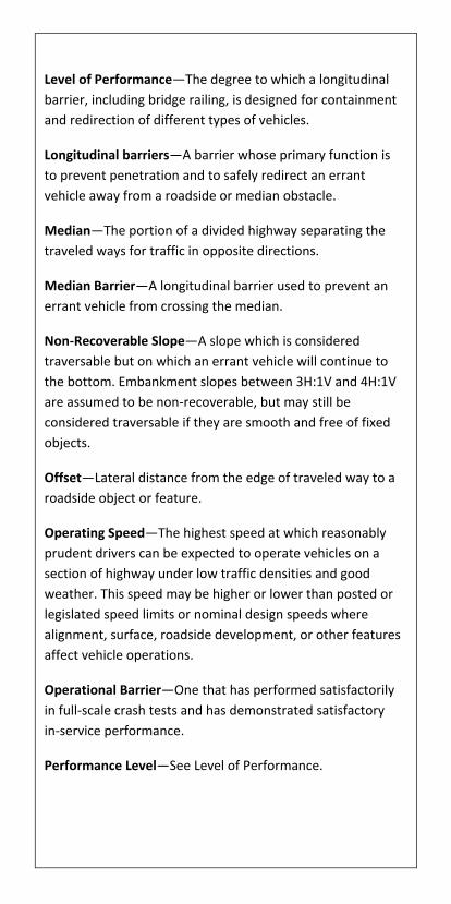
Level of Performance—The degree to which a longitudinal
barrier, including bridge railing, is designed for containment
and redirection of different types of vehicles.
Longitudinal barriers—A barrier whose primary function is
to prevent penetration and to safely redirect an errant
vehicle away from a roadside or median obstacle.
Median—The portion of a divided highway separating the
traveled ways for traffic in opposite directions.
Median Barrier—A longitudinal barrier used to prevent an
errant vehicle from crossing the median.
Non-Recoverable Slope—A slope which is considered
traversable but on which an errant vehicle will continue to
the bottom. Embankment slopes between 3H:1V and 4H:1V
are assumed to be non-recoverable, but may still be
considered traversable if they are smooth and free of fixed
objects.
Offset—Lateral distance from the edge of traveled way to a
roadside object or feature.
Operating Speed—The highest speed at which reasonably
prudent drivers can be expected to operate vehicles on a
section of highway under low traffic densities and good
weather. This speed may be higher or lower than posted or
legislated speed limits or nominal design speeds where
alignment, surface, roadside development, or other features
affect vehicle operations.
Operational Barrier—One that has performed satisfactorily
in full-scale crash tests and has demonstrated satisfactory
in-service performance.
Performance Level—See Level of Performance.

Recoverable Slope—A slope on which a motorist may, to a
greater or lesser extent, retain, or regain control of a vehicle.
Slopes flatter than 4H:1V are generally considered
recoverable.
Recovery Area—Generally synonymous with clear zone.
Roadside—That area between the outside shoulder edge and
the right-of-way limits. The area between roadways of a
divided highway may also be considered roadside.
Roadside Barrier—A longitudinal barrier used to shield
roadside obstacles or no-traversable terrain features. It may
occasionally be used to protect pedestrians or “bystanders”
from vehicle traffic.
Roadside Signs—Roadside signs can be divided into 3 main
categories: overhead signs, large roadside signs, and small
roadside signs. Large roadside signs may be defined as those
greater than or equal to 50ft2 in area. Small roadside signs
may be defined as those less than 50ft2 in area.
Roadway—The portion of a highway, including shoulders for
vehicular use.
Shielding—The introduction of a barrier or crash cushion
between the vehicle and an obstacle or area of concern to
reduce the severity of impacts of errant vehicles.
Shy Distance—The distance from the edge of the traveled
way beyond which a roadside object will not be perceived as
an obstacle by the typical driver to the extent that the driver
will change the vehicle’s placement or speed.
Slope—The relative steepness of the terrain expressed as a
ratio or percentage. Slopes may be categorized as positive
(backslopes) or negative (foreslopes) or as a parallel or cross
slope (in relation to the direction of traffic).
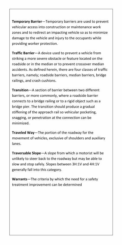
Temporary Barrier—Temporary barriers are used to prevent
vehicular access into construction or maintenance work
zones and to redirect an impacting vehicle so as to minimize
damage to the vehicle and injury to the occupants while
providing worker protection.
Traffic Barrier—A device used to prevent a vehicle from
striking a more severe obstacle or feature located on the
roadside or in the median or to prevent crossover median
accidents. As defined herein, there are four classes of traffic
barriers, namely; roadside barriers, median barriers, bridge
railings, and crash cushions.
Transition—A section of barrier between two different
barriers, or more commonly, where a roadside barrier
connects to a bridge railing or to a rigid object such as a
bridge pier. The transition should produce a gradual
stiffening of the approach rail so vehicular pocketing,
snagging, or penetration at the connection can be
minimized.
Traveled Way—The portion of the roadway for the
movement of vehicles, exclusive of shoulders and auxiliary
lanes.
Traversable Slope—A slope from which a motorist will be
unlikely to steer back to the roadway but may be able to
slow and stop safely. Slopes between 3H:1V and 4H:1V
generally fall into this category.
Warrants—The criteria by which the need for a safety
treatment improvement can be determined

1
Introduction Barrier systems are designed and installed for one primary
reason: to reduce the severity of a crash by preventing a
motorist from reaching a more hazardous fixed object or
terrain feature. The purpose of this document is to
summarize important information contained in the TxDOT
Roadway Design Manual and Standard Construction
Drawings that can be used in the field to ensure that all
barrier installations are built and maintained to current
standards and can be expected to perform acceptably when
hit.
Questions We Must Ask Ourselves
When reviewing proposed and existing barrier installations
in the field, we need to ask ourselves the following
questions:
1. Is an existing barrier installation still warranted?
2. Is the barrier system more hazardous than the condition being shielding?
3. If the barrier is installed as originally planned, is there a possibility of a motorist still reaching the hazard?
4. Can the barrier be extended to shield a secondary obstruction?
5. Are there any vertical obstructions within the barrier system’s design deflection?
6. Is the metal beam guard fence terminal within 200 feet of the start of another guard fence run and, if so, could the two runs be connected?
7. Does the slope need regrading?
8. Has the barrier height been reset after an overlay?
2
9. Is the best end treatment for the site being used?
10. Is barrier considered in sensitive areas such as school playgrounds and reservoirs?
11. Is there adequate soil support behind strong post metal beam guard fence shielding a slope or are longer posts required?
This document provides the information needed to answer
these and other questions pertaining to optimal design,
installation, and maintenance of barrier systems.
3
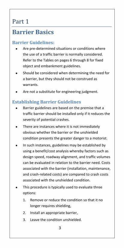
Part 1
Barrier Basics
Barrier Guidelines: Are pre-determined situations or conditions where
the use of a traffic barrier is normally considered.
Refer to the Tables on pages 6 through 8 for fixed
object and embankment guidelines.
Should be considered when determining the need for
a barrier, but they should not be construed as
warrants.
Are not a substitute for engineering judgment.
Establishing Barrier Guidelines Barrier guidelines are based on the premise that a
traffic barrier should be installed only if it reduces the
severity of potential crashes.
There are instances where it is not immediately
obvious whether the barrier or the unshielded
condition presents the greater danger to a motorist.
In such instances, guidelines may be established by
using a benefit/cost analysis whereby factors such as
design speed, roadway alignment, and traffic volumes
can be evaluated in relation to the barrier need. Costs
associated with the barrier (installation, maintenance,
and crash-related costs) are compared to crash costs
associated with the unshielded condition.
This procedure is typically used to evaluate three
options:
1. Remove or reduce the condition so that it no
longer requires shielding,
2. Install an appropriate barrier,
3. Leave the condition unshielded.

4
Considerations Consider eliminating short lengths of guard fence
since these sections are often less effective than no
barrier at all.
Avoid short gaps between guard fence installations by
making guard fence continuous where the points of
need are determined to be about 200 feet apart or
less.
Consider keeping the slope clear of fixed objects when
guard fence is not required due to the height of the
slope.
Consider guard fence in sensitive areas such as school
playgrounds or reservoirs.
Clear Zone The term “clear zone” is used to designate an area bordering
the roadway, starting at the edge of the traveled way, which
is available for safe use by errant vehicles. Safe use generally
means the slope is flat enough and free of fixed object
hazards so a motorist leaving the road is able to stop and
return to the roadway safely.
The clear zone distances shown below represent minimum
recommended distances and are based on limited data.

5
The best answer to the question “How wide should the clear
zone be ?” is “As wide as practical in each situation – but at
least as wide as the distances, shown in the Table below”.
Design Clear Zone
Location Functional
Class
Design
Speed
(MPH)
Avg. Daily
Traffic
Clear Zone Width
(ft)
Min. Desirable
Rural
Freeway All All 30 (16 for ramps)
Arterial All 0 – 750
750 – 1,500
>1,500
10
16
30
16
30
--
Collector ≥50
≤45 All 10 --
Local All All 10 --
Suburban All All
< 8,000
8,000 – 12,000
12,000 – 16,000
>16,000
10
10
10
20
10
20
25
30
Urban
Freeway All All 30 (16 for ramps)
All (Curbed)
≥50 All
Use above
suburban criteria
in so far as
available border
width permits
≤ 45 All
4
from
curb
face
6
All
(Uncurbed)
≥ 50 All Use above
suburban criteria
≤ 45 All 10 --
See TxDOT Roadway Design Manual
6
Design Options (In order of preference) Remove the hazard.
Redesign the obstruction so it can be traversed safely.
Relocate the obstruction to a point where it is less
likely to be struck.
Reduce impact severity by using an appropriate
breakaway device or crash cushion.
Shield the obstruction with a longitudinal traffic barrier
if it cannot be eliminated, relocated or redesigned.
Delineate the obstruction if the above alternatives are
not practical or cost effective.
REMEMBER: Barrier can also be a hazard and should only be
used where the results of leaving the roadway and
overturning or striking a fixed object would be more severe
than the consequences of striking the barrier.
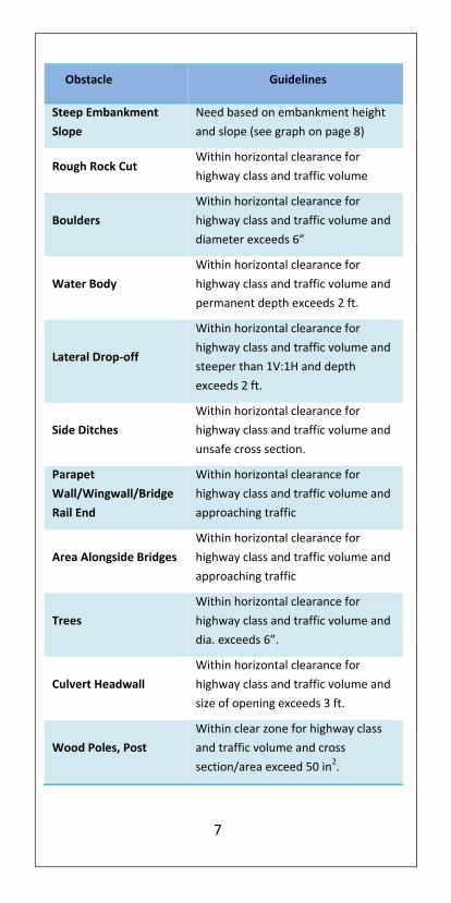
Roadside Obstacles
Roadside features that are normally considered for shielding
are shown in the table below. Note that many man-made
hazards can be redesigned or relocated to make shielding
unnecessary. Traffic volumes and speeds, roadway
geometrics, and the offset distances to the hazard are
factors that should be considered when deciding on barrier
installation. The following conditions within the clear zone
are normally considered more hazardous than a roadside
barrier:
7
Obstacle Guidelines
Steep Embankment
Slope
Need based on embankment height
and slope (see graph on page 8)
Rough Rock Cut Within horizontal clearance for
highway class and traffic volume
Boulders
Within horizontal clearance for
highway class and traffic volume and
diameter exceeds 6”
Water Body
Within horizontal clearance for
highway class and traffic volume and
permanent depth exceeds 2 ft.
Lateral Drop-off
Within horizontal clearance for
highway class and traffic volume and
steeper than 1V:1H and depth
exceeds 2 ft.
Side Ditches
Within horizontal clearance for
highway class and traffic volume and
unsafe cross section.
Parapet
Wall/Wingwall/Bridge
Rail End
Within horizontal clearance for
highway class and traffic volume and
approaching traffic
Area Alongside Bridges
Within horizontal clearance for
highway class and traffic volume and
approaching traffic
Trees
Within horizontal clearance for
highway class and traffic volume and
dia. exceeds 6”.
Culvert Headwall
Within horizontal clearance for
highway class and traffic volume and
size of opening exceeds 3 ft.
Wood Poles, Post
Within clear zone for highway class
and traffic volume and cross
section/area exceed 50 in2.
8
Obstacle Guidelines
Bridge Piers,
Abutments at
Underpasses
Within horizontal clearance for
highway class and traffic volume
Retaining Walls
Within horizontal clearance for
highway class and traffic volume and
not parallel to travel way.
Ref: TxDOT Roadway Design Manual.
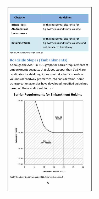
Roadside Slopes (Embankments) Although the AASHTO RDG graph for barrier requirements at
embankments suggests that slopes steeper than 1V:3H are
candidates for shielding, it does not take traffic speeds or
volumes or roadway geometrics into consideration. Some
transportation agencies have developed modified guidelines
based on these additional factors.
Barrier Requirements for Embankment Heights
TxDOT Roadway Design Manual, 2013, Figure A-1, page A-5

9
Barriers A roadside barrier is a longitudinal barrier used to shield
motorists from natural and man-made obstacles located
along either side of a traveled way. They are usually
categorized as rigid, semi-rigid or flexible depending on
their deflection characteristics when impacted.
Rigid Systems: The F-Shape Barrier has the
same basic geometry as the
New Jersey barrier, but the
"break-point" between the
lower and upper slopes is 10
inches above the pavement.
This modification results in less
vehicle climb in severe impacts
and improved post-crash
trajectories.
The 7.5 inch horizontal distance from the toe of the F-shape
to its top corner also reduces the roll angle of impacting
trucks and other vehicles with high centers-of-gravity. TL-4:
32” Tall and TL-5: 42” Tall.
The Single Sloped Barrier has a
constant 10.8 degree slope and
its crash performance is similar
to the F-shape barrier.
Low Profile Barrier is a TL-2
system and can be used in
work zone applications on
roads posted for 45 mph or
less.
10
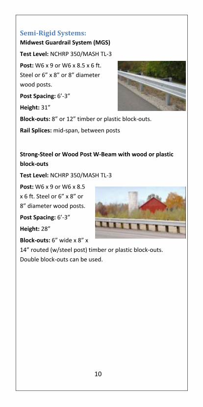
Semi-Rigid Systems:
Midwest Guardrail System (MGS)
Test Level: NCHRP 350/MASH TL-3
Post: W6 x 9 or W6 x 8.5 x 6 ft.
Steel or 6” x 8” or 8” diameter
wood posts.
Post Spacing: 6’-3”
Height: 31”
Block-outs: 8” or 12” timber or plastic block-outs.
Rail Splices: mid-span, between posts
Strong-Steel or Wood Post W-Beam with wood or plastic
block-outs
Test Level: NCHRP 350/MASH TL-3
Post: W6 x 9 or W6 x 8.5
x 6 ft. Steel or 6” x 8” or
8” diameter wood posts.
Post Spacing: 6’-3”
Height: 28”
Block-outs: 6” wide x 8” x
14” routed (w/steel post) timber or plastic block-outs.
Double block-outs can be used.

11
Flexible Systems:
High tension cable barriers (Propriety Systems) is installed
with a significantly greater tension in the cables than
generic, low-tension, three-cable systems. The deflection of
these systems depends on the type of system, the post
spacing and the distance between anchors. The high-tension
systems also result in less damage to the barrier and usually
the cables remain at the proper height after an impact which
damages several posts. Note that the cable heights above
ground may vary by manufacturer and by test level.
All of these systems have been tested successfully on slopes
as steep as 1V:4H, but lateral placement must follow
manufacturer’s recommendations.
Brifen Wire Rope Safety Fence (WRSF) by Brifen USA
http://www.brifenusa.com/
Post: Z-shaped post, can be
driven or socketed
Cable: 3 or 4 cable
combination. Top cable is
placed in a center slot at top
of the post and cables 2 and
the lower cables are
interweaved around the posts.
Typical Post Spacing: 10.5 to 21 ft.
12
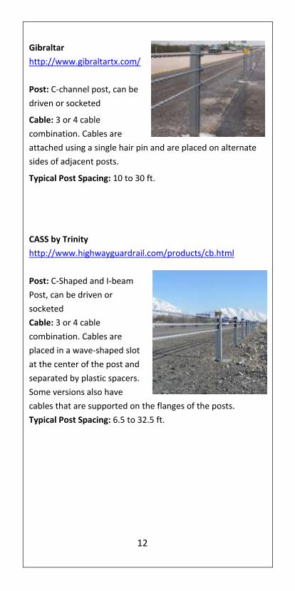
Gibraltar
http://www.gibraltartx.com/
Post: C-channel post, can be
driven or socketed
Cable: 3 or 4 cable
combination. Cables are
attached using a single hair pin and are placed on alternate
sides of adjacent posts.
Typical Post Spacing: 10 to 30 ft.
CASS by Trinity
http://www.highwayguardrail.com/products/cb.html
Post: C-Shaped and I-beam
Post, can be driven or
socketed
Cable: 3 or 4 cable
combination. Cables are
placed in a wave-shaped slot
at the center of the post and
separated by plastic spacers.
Some versions also have
cables that are supported on the flanges of the posts.
Typical Post Spacing: 6.5 to 32.5 ft.
13
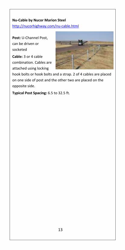
Nu-Cable by Nucor Marion Steel
http://nucorhighway.com/nu-cable.html
Post: U-Channel Post,
can be driven or
socketed
Cable: 3 or 4 cable
combination. Cables are
attached using locking
hook bolts or hook bolts and a strap. 2 of 4 cables are placed
on one side of post and the other two are placed on the
opposite side.
Typical Post Spacing: 6.5 to 32.5 ft.
14
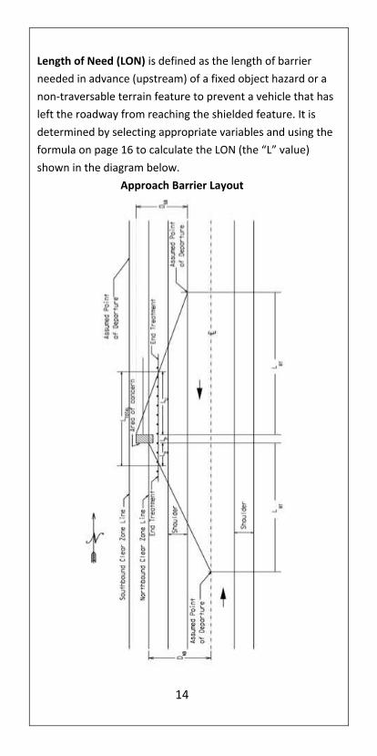
Length of Need (LON) is defined as the length of barrier
needed in advance (upstream) of a fixed object hazard or a
non-traversable terrain feature to prevent a vehicle that has
left the roadway from reaching the shielded feature. It is
determined by selecting appropriate variables and using the
formula on page 16 to calculate the LON (the “L” value)
shown in the diagram below.
Approach Barrier Layout

15
CZ Clear Zone width CZSB Clear Zone width for southbound traffic CZNB Clear Zone width for northbound traffic LRT Length of roadside travel DSB Distance from edge of southbound travel lane to far
side of area of concern or to outside edge of clear zone whichever is least.
DNB Distance from edge of northbound travel lane to far side of area of concern or to outside edge of clear zone whichever is least.
Lu Guard fence length upstream of area of concern. Lp Guard fence length parallel to area of concern. LD Guard fence length downstream of area of concern. LTOTAL Length of guard fence needed. (Lu + Lp +LD).
TxDOT Length of Need Procedure:
To determine needed length of guard fence for a given obstacle, design equations have been formulated for low volume (ADT 750 or less) and higher volume (ADT more than 750) conditions. A clear zone width of 16 ft and length of roadside travel of 200 ft are incorporated in the low volume design equation (for use on roadways when the present ADT volume is 750 or less). If the clear zone required is less than 16 ft and the present ADT is 750 or less the shorter distance can be used in lieu of 16 ft. to calculate the LON.
1. Choose an appropriate D distance as it is the most critical part of the design process. This distance should include all features or hazards that need to be shielded, up to the design clear zone at each site.
2. Select a Runout Length (200’ or 250’, based on ADT) from the table below.
3. Determine the location of the barrier face relative to the edge of the travel lane (G).
4. Calculate the Length of Need (L) from the following equation and round the calculated value up to the nearest 12.5-foot or 25-foot rail segment:
Low Volume (ADT < 750)
𝐿 = 200 −200
𝐷x G
× G

16
Where: D = Distance from edge of travel lane to far side of hazard, or 16 ft, whichever is less. G = Guard fence offset from edge of travel lane, ft.
High Volume (ADT > 750)
Where: D = Distance from edge of travel lane to far side of hazard, or 30 ft, whichever is less. G = Guard fence offset from edge of travel lane, ft.
TxDOT Runout Lengths
Design
Speed
(mph)
Runout Length (LR)
Given Traffic Volume
(ADT) (ft)
Under
750 Over 750
80 200 250
70 200 250
60 200 250
50 200 250
40 200 250
30 200 250
Ref: TxDOT Location and Design Manual, Figure 602-1E, April 2013
Length of Need for Opposing Traffic
X (or L) is determined using the same equation.
All lateral dimensions are measured from the centerline for a two-lane roadway. See the layout on page 14.
There are three ranges of clear zone width, LC (or D), which deserve special attention:
𝐿 = 250 −250
𝐷x G
× G
17
1. If the barrier is beyond the appropriate clear zone for opposite direction traffic, no additional barrier and no crashworthy end treatment is required. (NOTE: an appropriate barrier anchor remains necessary to ensure proper containment and redirection for near-side impacts).
2. If the barrier is within the appropriate clear zone but the area of concern is beyond it, no additional barrier is required; however a crashworthy end treatment should be used.
3. If the area of concern is within the clear zone for opposing traffic, the barrier must be extended to prevent opposite-direction hits.
Length of Need (LON) Field Check: A straightforward
method to verify correct LON in the field is to stand on the
roadway edge directly opposite the shielded feature, and
then pace off the appropriate runout length based on ADT
(i.e., 200 or 250 feet) upstream along the edge line. At that
point, turn and look at the shielded area. If the proposed
(or actual) guardrail installation crosses that line of sight,
then the area is adequately covered. (NOTE: if the terrain
makes it unlikely for a vehicle to reach the hazard from that
point (as might be the case if there is a traversable, non-
recoverable slope beyond the rail), the installation may be
longer than needed. On the other hand, if the intervening
terrain is also hazardous or if there are other significant
obstacles in the immediate vicinity, it may be desirable to
extend the barrier to shield all of the dangerous
conditions.)
Additional Design Considerations
Although it is critical that the correct length of need be
installed, there are several other placement considerations
essential to good barrier performance. These include
adequate deflection distances behind each type of barrier,

18
barrier height, and the location of barrier on slopes and
behind curbs. These factors are discussed in the next
sections.
Design Deflection Distance is based on the results of 62-
mph impacts into the barrier at a 25-degree impact angle
by the NCHRP Report 350 or MASH pickup truck. In the
field, actual deflections can be much greater (or less)
depending on actual impact conditions. Note that the
AASHTO RDG measures the distance from the back of the
posts.
Height Measurement The minimum height of Strong-Steel
Post metal beam guard fence is 28” and MGS is 31”,
measured as shown below or from the gutter line when set
above a curb. If set behind a sidewalk barrier height should
be set from the sidewalk elevation. For high tension cable
barriers, the height of the top and bottom cables is critical
and must meet manufacturers’ specifications.

19
Barrier Placement on Slopes Barrier, regardless of type, performs best when an impacting
vehicle is stable when contact is first made. Since vehicles
running off the road at high speeds tend to become airborne
and are likely to override barrier placed on a slope, the
following guidelines apply:
Do not place metal beam guard fence on slopes steeper than 1V:6H. Note: TxDOT requires 1V:10H
Metal beam guard fence systems can be placed anywhere on 1V:10H or flatter slopes.
MGS barrier can be installed on 1V:8H slopes but 1V:10H is preferred.
When the slopes are between 1V:10H and 1V:6H, the face of the barrier must not be between 2 to 12 feet beyond the grade hinge point.
Strong post metal beam guard fence need 2 feet of soil support behind the rail for support. When 2 feet is not obtainable, strong posts that are a minimum of 1 foot longer shall be provided.
High tension cable barriers can be placed anywhere on a 1V:6H or flatter roadside slope, but there some placement restrictions when used in a median application. Most proprietary systems can be placed on 1V:4H slopes, but manufacturers’ recommendations must be followed.
See AASHTO Roadside Design Guide, 4th Edition, Figure 5-38, pg 5-47.

20
Guard fence and Curb Curbs do not have a significant redirection capability and can
have the same type effect on vehicle trajectory as slopes,
i.e., wheel impact with a curb can cause a vehicle to vault
over a barrier placed above or beyond it. The following
guidelines apply:
Guard fence should not be used with curb installation
on high speed (Design Speed of 50 mph and higher),
rural roads.
When guard fence/curb combinations are
unavoidable, the curb type and barrier placement
should follow the recommendations shown in the
details below. Any curb in front of a guard fence
terminal should be limited to a 2 inch height.
If the curb exceeds 4 inches, follow these guidelines:
1. Strong post metal beam guard fence should be used.
2. Stiffen the guard fence
Add a rubrail or
Double nest the rail or
Bolt a W-beam to back of the posts
3. Curb must be flush with, or slightly behind, the face of
the guard fence.
4. The guard fence height is measured from the edge of
travel lane to the top of rail when the guard fence is
placed in front of or at the face of the curb.
5. When standard metal beam guard fence is placed
behind curb, the face of the barrier should be aligned
with the face of the curb.
6. For 31” height metal beam guard fence, the face of
the rail may be 6” beyond the face of the curb or 8ft
beyond face of curb.

21
Guard fence and Trees Generally guard fence is not used to shield utility
poles or trees. However, individual trees and poles
that are in vulnerable locations and cannot be
removed or relocated are sometimes shielded.
Where guard fence is used in front of poles or trees
due to other obstructions barrier deflection must be
considered.
Consider removing trees where they are an
obstruction and in locations where they are likely to
be hit.
Use crash history at similar sites, scars indicating
previous crashes or field reviews to determine
removable trees.
Tree removal is usually a preferred option but an
assessment regarding its expense and effectiveness
should be considered.
Roadways through wooded areas with heavy
nighttime traffic volumes, frequent fog, and narrow
lanes should be well delineated.
Pavement markings and post mounted delineators are
among the most effective and least costly
improvements that can be made to a roadway.
Connections to Bridge Barriers Since there are numerous bridge barrier designs currently in
place on Texas highways, the attachment details shown in
the latest Design Standards for new construction will not
always be directly applicable for every project. However,
crashworthy designs can be developed if three concerns are
met: an adequate transition between the bridge end and the
approach guardrail, an adequate attachment to the bridge
barrier itself, and the elimination of any potential snag
points at the bridge end.
22
A transition is simply a gradual stiffening of the
approach guard fence at the bridge end so the rail
cannot deflect enough to result in a vehicle
“pocketing” when it reaches the rigid bridge barrier.
A structurally adequate attachment of the guard
fence to the bridge barrier is shown on the transition
details as well. This detail is needed to prevent the
approach railing from pulling free from the bridge
barrier. Some existing bridge railings may not be
structurally adequate to support such a connection. In
such situations extending the guard fence across the
structure eliminates the need for a structural
connection at the bridge end and may increase the
capacity of the bridge barrier itself.
Finally, if the bridge barrier is significantly higher than
the approach railing, a truck or SUV impacting the
approach railing could lean over the railing far enough
to snag on the end of the bridge barrier, or if no
rubrail or concrete curb is used, a vehicle’s tire could
fold under the guard fence and snag on the bottom
edge of the bridge parapet.

23
REF: TxDOT Standard Drawing; GF(31) TR

24
Guard fence at Intersections and Driveways When secondary roads or driveways intersect a main road so
close to a bridge or other hazard that a full run of barrier
cannot be installed, a strong post metal beam guard fence
can be curved around the radius where the two roads meet.
While the site conditions can vary greatly, there are two
major concerns that should be addressed.
1. If the hazard is a bridge end or pier, a crashworthy transition design is required. A crash cushion can be used if the space is too limited to use a standard transition. The section of barrier along the primary road must be long enough and designed to react in tension to redirect impacting vehicles away from the shielded rigid object.
2. Oftentimes the feature traversed by a structure or another hazardous feature between the intersecting road and the structure can be shielded using a curved rail design. By using a curved rail design, high angle impacts into the curved section are likely. To reduce the risk of a vehicle going through or over the metal beam, modifications can be made to the posts, the metal beam-to-post connections, and the end treatment along the intersecting road or driveway. TxDOTs typical treatment at such locations is shown here.

25
TxDOT Short Radius
26
Part 2
Terminals and Crash Cushions
Terminals Crashworthy terminals anchor a barrier installation and
are designed to eliminate spearing or vaulting when hit
head-on, or redirect a vehicle away from the shielded
object or terrain feature when the barrier is struck on the
traffic face near the terminal. Texas requires` TL-3 end
terminals on the NHS.
Definitions:
Energy Absorbing Terminals can stop vehicles in relatively
short distances in direct end-on impacts (usually 50 feet
or less depending on type of terminal).
NOTE:
At the trailing end of guard fence, a distance of 50 feet
beyond the end treatment is to be kept clear of all
roadside obstructions (hazards) or the rail maybe
extended to shield such secondary hazards.
This "downstream clear zone" is intended to minimize
the likelihood that a vehicle may be forced into an
obstruction by the barrier.
On two lane highways with two-way traffic, provide
crashworthy end treatments on both the approach and
trailing ends of the guard fence when the trailing ends
are within the clear zone of opposing traffic.
On four-lane divided highways, use crashworthy end
treatments on the approach ends. If the departure rail is
within the clear zone for opposing traffic, provide end
treatments on both the approach and trailing ends.
Note that oftentimes no rail is needed on the departure
ends of bridges on divided roadways unless site specific
circumstances require additional barrier.

27
Types of Terminals The following terminals are those primarily used in Texas.
For additional terminals go to the FHWA website at
http://safety.fhwa.dot.gov/roadway_dept/policy_guide/ro
ad_hardware/barriers/index.cfm
Energy Absorbing Terminals
Used for single runs of strong post metal beam guard
fence
Redirection begins beyond the third post
Extruder Terminal ET-2000 Plus
http://www.highwayguardrail.com/products/etplus.html
Test Level: NCHRP 350: TL-2 and TL-3
Characteristics:
Tangent terminal.
Rectangular impact front face (Extruder head).
Rectangular holes in 1st rail support the tabs of the cable
anchor bracket.
Steel HBA and SYTP and wood post options are available.
SYTP Retrofit in tube sleeve option available.
End of W-beam rail with offset of 0’ to 2’-0”.
** Effective October 28, 2014, the ET-Plus system is
suspended as an alternative in contracts and is
discontinued for use in new installations.

28
Sequential Kinking Terminal (SKT-350)
http://roadsystems.com/skt.html
Test Level: NCHRP 350: TL-2 and TL-3
Characteristics:
Tangent terminal.
Square impact front face.
Has a feeder chute (channel section that surrounds
the rail) which gets wider at the downstream end.
Breakaway steel end posts #1 and #2 and standard
steel metal beam guard fence posts #3 and beyond.
Rail has 3 (1/2” x 4” long) slots in the valley of the rail.
There may be 5 additional slots (1/2” x 4” long) on
both the top and bottom corrugations of the w-beam
section, which makes it interchangeable with the
FLEAT system.
Cable anchor bracket is fully seated on the shoulder
portion of the cable anchor bolts.
All hinge steel post, plug weld steel posts, or wood
posts available.
End of metal beam rail with offset of 0’ to 2’-0”.

29
X-Lite
http://www.barriersystemsinc.com/xlite-end-terminal
Test Level: NCHRP 350: TL-3
Characteristics:
Rectangular Impact Face.
All steel driven posts.
Uses a slider mechanism between post 1 and 2 that gathers and retains the rail when hit.
The anchor consists of posts #1 and #2 connected by tension struts and a soil plate below grade on post #2.
Both Tangent and Flared Layout.
Softstop
http://www.highwayguardrail.com/products/SoftStop.html
Test Level: MASH TL-3
Characteristics:
Rectangular Impact Face.
All steel driven posts.
Breakaway steel posts at #1 and #2, standard steel guardrail posts #3 and beyond.
Impact head flattens and extrudes w-beam guardrail upon end-on impact.
30
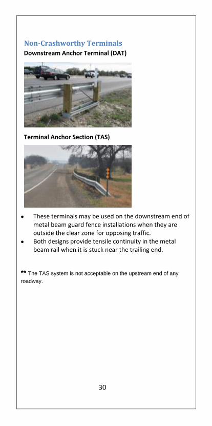
Non-Crashworthy Terminals
Downstream Anchor Terminal (DAT)
Terminal Anchor Section (TAS)
These terminals may be used on the downstream end of metal beam guard fence installations when they are outside the clear zone for opposing traffic.
Both designs provide tensile continuity in the metal beam rail when it is stuck near the trailing end.
** The TAS system is not acceptable on the upstream end of any
roadway.
31
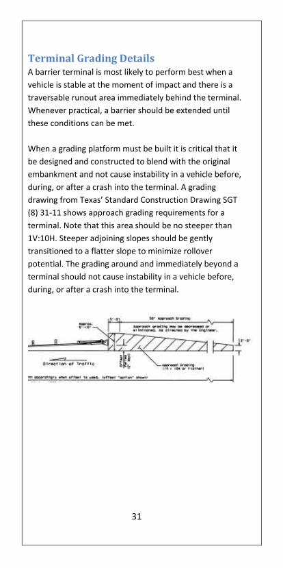
Terminal Grading Details A barrier terminal is most likely to perform best when a
vehicle is stable at the moment of impact and there is a
traversable runout area immediately behind the terminal.
Whenever practical, a barrier should be extended until
these conditions can be met.
When a grading platform must be built it is critical that it
be designed and constructed to blend with the original
embankment and not cause instability in a vehicle before,
during, or after a crash into the terminal. A grading
drawing from Texas’ Standard Construction Drawing SGT
(8) 31-11 shows approach grading requirements for a
terminal. Note that this area should be no steeper than
1V:10H. Steeper adjoining slopes should be gently
transitioned to a flatter slope to minimize rollover
potential. The grading around and immediately beyond a
terminal should not cause instability in a vehicle before,
during, or after a crash into the terminal.
32
Crash Cushions Crash cushions are generally used to shield hazards in
freeway gore areas or the ends of permanent or
temporary traffic barriers.
For additional commonly used attenuators throughout
the U.S., go to the FHWA website at
http://safety.fhwa.dot.gov/roadway_dept/policy_guide/road_h
ardware/barriers/index.cfm
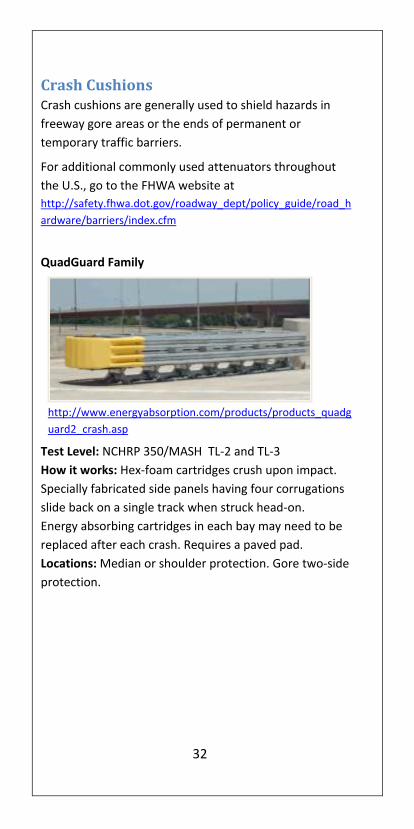
QuadGuard Family
http://www.energyabsorption.com/products/products_quadg
uard2_crash.asp
Test Level: NCHRP 350/MASH TL-2 and TL-3
How it works: Hex-foam cartridges crush upon impact.
Specially fabricated side panels having four corrugations
slide back on a single track when struck head-on.
Energy absorbing cartridges in each bay may need to be
replaced after each crash. Requires a paved pad.
Locations: Median or shoulder protection. Gore two-side
protection.

33
TAU-II
http://www.barriersystemsinc.com/#/tau-ii
Test Level: NCHRP 350/MASH TL-2 and TL-3
How it works: Energy absorbing cartridges crush upon
impact. Thrie beam panels slide back when struck head-on.
Anchored at the front and rear of system.
Energy absorbing cartridges in each bay may need to be
replaced after each crash. Requires a paved pad.
Locations: Median or shoulder protection. Gore two-side
protection.
Trinity Attenuating Crash Cushion (TRACC)
http://www.highwayguardrail.com/products/tracc.html
Test Level: NCHRP 350 TL-2 and TL-3
How it works: Consists of a series of w-beam fender panels
and an impact face which absorbs energy by cutting metal
plates on the top sides of the guidance tracks when forced
backward in an end on impact. Requires Paved Pad.
Locations: Median or shoulder protection.Gore two-side
protection.

34
REACT 350
http://www.energyabsorption.com/products/products_react3
50_impact.asp
Test Level: NCHRP 350 TL-2 and TL-3
How it works: Hollow high molecular weight, high density
polyethylene cylinders crush upon impact.
Cables on the side are for side impacts. Requires a paved
pad.
Locations: Median or shoulder protection. Gore two-side
protection.
QuadGuard Elite Family
http://www.energyabsorption.com/products/products_qu
adguard_elite.asp
Test Level: NCHRP 350 TL-2 and TL-3
How it works: High Density Polyethylene cylinders and
flex-belt nose collapse upon impact. Specially fabricated

35
side panels having four corrugations slide back on a single
track when struck head-on. Requires a paved pad.
Locations: Median or shoulder protection. Gore two-side
protection.
Smart Cushion Innovation (SCI)
http://www.workareaprotection.com/attenuator.htm
Test Level: NCHRP 350 TL-2 and TL-3
How it works: Hydraulic cylinders in the attenuator provides
resistance to stop a vehicle before it reaches the end of the
cushion’s usable length.
Requires a paved pad.
Locations: Median or shoulder protection. Gore two-side
protection.

36
Hybrid Energy Absorption Reusable Terminal
http://www.highwayguardrail.com/products/heart.html
Test Level: NCHRP 350 TL-3
How it works: High Molecular Weight / High Density
Polyethylene side panels connected to steel diaphragms
mounted on tubular steel tracks which compress upon
impact. Requires a paved pad.
Locations: Median or shoulder protection. Gore two-side
protection.
QUEST
Test Level: NCHRP 350 TL-2 and TL-3
How it works: Designed to attach to a concrete median
barrier. Consists of a series of W-beam fender panels
supported by diaphragms with a trigger mechanism at the
nose that releases the front assembly for end on hits.

37
BEAT-SSCC (Single Sided Crash Cushion)
http://www.roadsystems.com/beat-sscc.html
Test Level: NCHRP 350 TL-3
How it works: Mandrel section of the impact head
bursts the tubing to absorb the impact energy. Attaches
directly to rigid barriers, bridge rails and abutments.
Locations: Shoulder protection. Ground mounted or
surface mounted post on a concrete pad.
Work Zone Impact Attenuators ONLY
Absorb 350
http://www.barriersystemsinc.com/#/absorb-350
Test Level: NCHRP 350 TL-2 and TL-3
How it works: Plastic waterfilled elements allow vehicles to
be decelerated.
Locations: Any locations where it is safe for the post impact
trajectories to be on the back side of the system.

38
SLED
http://traffixdevices.com/cgi-
local/SoftCart.exe/newproducts.htm?L+scstore+tsjv8007fff838f8+1364
541558
Test Level: NCHRP 350 TL-2 and TL-3
How it works: Plastic waterfilled elements allow vehicles to
be decelerated.
Locations: Any locations where it is safe for the post impact
trajectories to be on the back side of the system.
ACZ-350
http://www.energyabsorption.com/products/produ
cts_acz.asp Test Level: NCHRP 350 TL-3
How it works: Plastic waterfilled elements allow vehicles to
be decelerated.
Locations: Any locations where it is safe for the post impact
trajectories to be on the back side of the system.
39
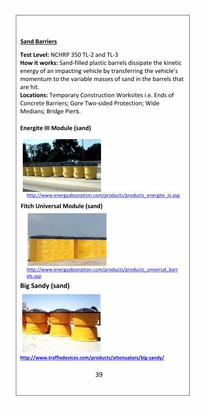
Sand Barriers
Test Level: NCHRP 350 TL-2 and TL-3 How it works: Sand-filled plastic barrels dissipate the kinetic energy of an impacting vehicle by transferring the vehicle’s momentum to the variable masses of sand in the barrels that are hit. Locations: Temporary Construction Worksites i.e. Ends of Concrete Barriers; Gore Two-sided Protection; Wide Medians; Bridge Piers.
Energite III Module (sand)
http://www.energyabsorption.com/products/products_energite_iii.asp
Big Sandy (sand)
http://www.traffixdevices.com/products/attenuators/big-sandy/
Fitch Universal Module (sand)
http://www.energyabsorption.com/products/products_universal_barrels.asp

40
Crashguard
http://plasticsafety.com/Products/Crash-Cushion/CrashGard-Sand-Barrel-
System.aspx

41
Part 3
Maintenance
Metal beam guard fence systems must be kept in good
working condition (near “as-built condition”) if they are to
contain and redirect impacting vehicles. Some deterioration
occurs as a result of crash damage and environmental
degradation. Much of this damage can be considered
“cosmetic” and may not measurably affect barrier
performance. However, some kinds of damage may
seriously degrade performance such as those listed below in
the Longitudinal Barrier Damage and Terminal Damage
sections. Repairs to these types of damage should be given
priority.
While it is not practical to quantitatively define “in a timely
manner”, each identified damaged barrier site must be
assessed, prioritized and scheduled for repairs based upon
risk exposure (highway type, extent of barrier/terminal
damage, potential for being restruck within the repair time
window).
Longitudinal Barrier Damage The types of guard fence damage listed below may result
in inadequate structural and substandard redirective
performance.
Vertical tears in the W-beam rail that begin at the
top or bottom edge. These are likely to result in rail
separation in a subsequent crash.
Similarly, holes in the rail resulting from damage or
deterioration that reaches the top or bottom of a rail
or one hole with a section greater than 1 inch or
several holes with a dimension less than 1 inch within
a 12.5-foot length of rail.
More than 2 missing or ineffective splice bolts.
42
More than 9 inches of lateral deflection over a 25-foot
length of rail.
Top rail height more than 2 inches lower than the
original rail height.
Rail flattening that increases the W-beam section width
from its original 12 inches.
Terminal Damage
These types of guard fence terminal damage can result in
inadequate performance if hit:
Broken or damaged end posts.
Missing or very slack rail-to-end post cables.
Missing cable bearing plate at end posts.
Impact head not properly aligned with W-beam rail
elements.
W-beam rail element not properly seated in the impact
head.
The following pages consist of excerpts from NCHRP Report
656, Criteria for the Restoration of Longitudinal Barrier. Note
that the types and degree of damage to the barrier itself and
to barrier terminals is prioritized as High, Medium, or Low.
These rankings, along with the perceived likelihood of a
second impact in the same location can be used to set repair
priorities. There are constant advancements in roadside
safety hardware. Some of the examples may not pertain to
every model of proprietary equipment. Please use the
information below when pertinent per the corresponding
standards and installation manuals.
Repair priority scheme
Priority Level Description
High A second impact results in unacceptable
safety performance including barrier
penetration and/or vehicle rollover.
Medium A second impact results in degraded but
not unacceptable safety performance.

43
Low A second impact results in no discernible
difference in performance from an
undamaged barrier.

44
W-beam Barrier Repair Threshold
Damage Mode: Post and Rail Deflection
Relative
Priority
Repair Threshold
High One or more of the following thresholds: • More than 9 inches of lateral deflection
anywhere over a 25 ft length of rail. • Top of rail height 2 or more inches lower
than original top of rail height.
Medium 6-9 inches lateral deflection anywhere over a 25 ft length of rail.
Low Less than 6 inches of lateral deflection over 25 ft length of rail.
45
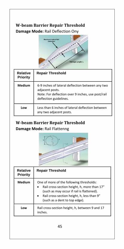
W-beam Barrier Repair Threshold
Damage Mode: Rail Deflection Ony
Relative Priority
Repair Threshold
Medium 6-9 inches of lateral deflection between any two adjacent posts. Note: For deflection over 9 inches, use post/rail deflection guidelines.
Low Less than 6 inches of lateral deflection between any two adjacent posts.
W-beam Barrier Repair Threshold
Damage Mode: Rail Flattenng
Relative Priority
Repair Threshold
Medium One of more of the following thresholds:
Rail cross-section height, h, more than 17” (such as may occur if rail is flattened).
Rail cross-section height, h, less than 9” (such as a dent to top edge).
Low Rail cross-section height, h, between 9 and 17 inches.
46
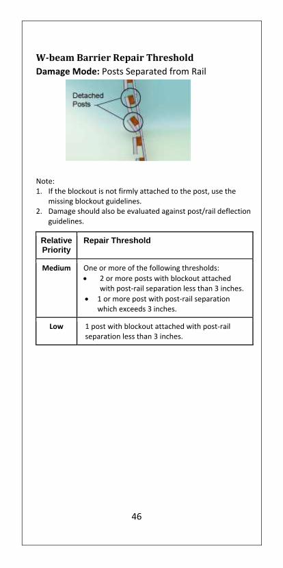
W-beam Barrier Repair Threshold
Damage Mode: Posts Separated from Rail
Note: 1. If the blockout is not firmly attached to the post, use the
missing blockout guidelines. 2. Damage should also be evaluated against post/rail deflection
guidelines.
Relative Priority
Repair Threshold
Medium One or more of the following thresholds:
2 or more posts with blockout attached with post-rail separation less than 3 inches.
1 or more post with post-rail separation which exceeds 3 inches.
Low 1 post with blockout attached with post-rail separation less than 3 inches.

47
W-beam Barrier Repair Threshold
Damage Mode: Missing/Broken Posts
W-beam Barrier Repair Threshold Damage Mode: Missing Blockout
Relative Priority
Repair Threshold
Medium Any blockouts
Missing
Cracked across the grain
Cracked from top or bottom blockout through post bolt hole
Rotted
Relative Priority
Repair Threshold
High One or more posts:
Missing
Cracked across the grain
Broken
Rotten
With metal tears

48
W-beam Barrier Repair Threshold
Damage Mode: Twisted Blockout
Relative Priority
Repair Threshold
Low Any misaligned blockouts, top edge of block 6
inches or more from bottom edge.
Note: Repairs of twisted blockout are relatively
quick and inexpensive
W-beam Barrier Repair Threshold
Damage Mode: Non-Manufactured holes
(such as crash induced holes, lug-nut damage, or holes
rusted-through the rail)
Height of
non-manufactured hole

49
Relative Priority
Repair Threshold
High One or more of the following thresholds:
More than 2 holes less than 1” in height in a 12.5’ length of rail.
Any holes greater than 1” height.
Any hole which intersects either the top or bottom edge of the rail.
Medium 1-2 holes less than 1” in height in a 12.5’ length of
rail.
W-beam Barrier Repair Threshold
Damage Mode: Damage at Rail Splice
Relative Priority
Repair Threshold
High More than 1 splice bolt:
Missing
Damaged
Visibly missing any underlying rail
Torn through rail
Medium 1 splice bolt:”
Missing
Damaged
Visibly missing any underlying rail
Torn through rail

50
W-beam Barrier Repair Threshold
Damage Mode: Vertical Tear
Relative Priority
Repair Threshold
High Any length vertical (transverse) tear
W-beam Barrier Repair Threshold
Damage Mode: Horizontal Tear
Relative Priority
Repair Threshold
Medium Horizontal (longitudinal) tears greater than 12
inches long or greater than 0.5 inches wide.
Note: for horizontal tears less than 12 inches in
length or less than 0.5 inches in height, use the
non-manufactured holes guidelines.
51
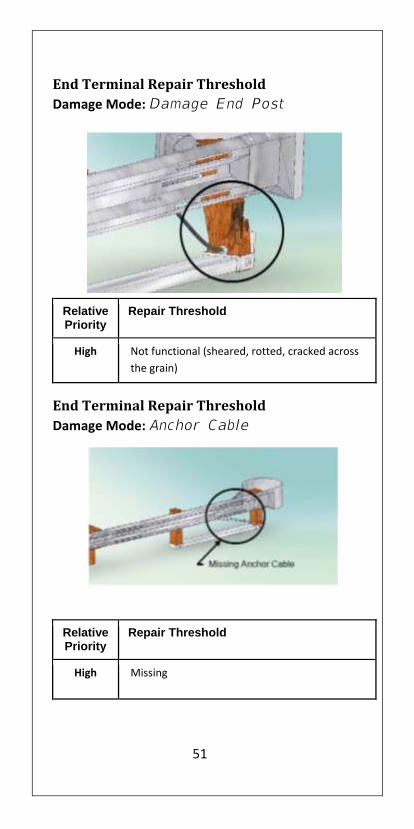
End Terminal Repair Threshold
Damage Mode: Damage End Post
Relative Priority
Repair Threshold
High Not functional (sheared, rotted, cracked across
the grain)
End Terminal Repair Threshold
Damage Mode: Anchor Cable
Relative Priority
Repair Threshold
High Missing
52
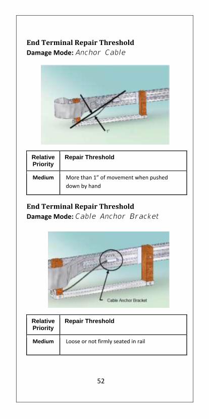
End Terminal Repair Threshold
Damage Mode: Anchor Cable
Relative Priority
Repair Threshold
Medium More than 1” of movement when pushed
down by hand
End Terminal Repair Threshold
Damage Mode: Cable Anchor Bracket
Relative Priority
Repair Threshold
Medium Loose or not firmly seated in rail

53
End Terminal Repair Threshold
Damage Mode: Stub Height
Relative Priority
Repair Threshold
Medium Height which exceeds 4”
End Terminal Repair Threshold
Damage Mode: Lag Screws (Energy
Absorbing Terminals Only)
Relative Priority
Repair Threshold
High Missing or failed lag Screws

54
End Terminal Repair Threshold
Damage Mode: Bearing Plate
Relative Priority
Repair Threshold
Medium Loose or Misaligned
End Terminal Repair Threshold
Damage Mode: Bearing Plate
Relative Priority
Repair Threshold
High Missing Bearing Plate

55
Repair/Upgrade/Remove
When safety hardware has been damaged to the extent
that it will not function properly if struck again, it should
be repaired or replaced as soon as practical. The
damaged area should be delineated with reflective cones,
tubes, or barrels and a “Guardrail Damage Ahead” sign
should be installed in the case of extreme damage.
Several questions should be answered before the
hardware is restored to its pre-crash condition:
Is the section of guardrail still required under current
design standards?
Can guardrail installation be avoided with the
elimination of the hazard or the flattening of the
slope?
If it is determined that the guardrail is still necessary
and more than approximately 25 percent or more of
the installation requires replacement, the installation
should be upgraded to current design standard.
Was the terminal or crash cushion a currently
acceptable design? If not, upgrade to current
standard.
NOTE: repair priority should be given to hardware along
curves or ramps or similar locations where subsequent
hits are likely to occur.
56
Resources
AASHTO, Roadside Design Guide, 2011
Manual on Uniform Traffic Control Devices for Streets and Highways, 2009
AASHTO, Manual for Assessing Safety Hardware, 2009
FHWA Hardware Policy and Guidance http://safety.fhwa.dot.gov/roadway_dept/policy_guide/road_hardware/
FHWA Longitudinal Barriers http://safety.fhwa.dot.gov/roadway_dept/policy_guide/road_hardware/barriers/
AASHTO Task Force 13 website https://www.aashtotf13.org/
AASHTO Guide to Standardized Highway Barrier Hardware;
https://www.aashtotf13.org/Barrier-Hardware.php
NHTSA FARS web site: http://www-fars.nhtsa.dot.gov/Main/index.aspx
Roadside Safety Pooled Fund sites:
MwRSF: http://mwrsf-qa.unl.edu/
TTI: http://www.roadsidepooledfund.org/
NCHRP Research Projects http://www.trb.org/NCHRP/Public/NCHRPProjects.aspx
Bridge Rail Guide: http://guides.roadsafellc.com/
NCHRP Report 350: http://onlinepubs.trb.org/onlinepubs/nchrp/nchrp_rpt_350-a.pdf

57
NOTES
Related Documents