64 [B] TECHNICAL SPECIFICATION FOR THE ITEM. Item No. 1 Site Clearance, Loosening and recompacting at OMC the original ground/ sub grade up to the required depth as directed by the Engineer and as per Technical Specifications MORTH Clause 201, 301 & 305. CLEARING AND GRUBBING 1.1 Scope This work shall consist of cutting, removing and disposing of all materials such as trees, bushes, shrubs, stumps, roots, grass, weeds, top organic soil not exceeding 150 mm in thickness, rubbish etc., which in the opinion of the Engineer are unsuitable for incorporation in the works, from the area of road land containing road embankment, drains, cross-drainage structures and such other areas as may be specified on the drawings or by the Engineer, it shall include necessary excavation, backfilling of pits resulting from uprooting of trees and stumps to required compaction, handling, salvaging, and disposal of cleared materials. Clearing and grubbing shall be performed in advance of earthwork operations and in accordance with the requirements of these Specifications. The Loosening, grading and recompacting of the original ground and sub grade is required to be carried out for excavation for Road way and Earth work for embankment for Road. The Loosening of the sub grade will be carried out to a depth as directed by the Engineer in Charge. The loosening of the sub grade will be carried out minimum to a depth of 10 cm. 1.2 Preservation of Property / Amenities Roadside trees, shrubs, any other plants, pole lines, fences, signs, monuments, buildings, pipelines, sewers and all highway facilities within or adjacent to the highway which are not to be disturbed shall be protected from injury or damage. The Contractor shall provide and install at his own expense, suitable safeguards approved by the Engineer for this purpose. During clearing and grubbing, the Contractor shall take all adequate precautions against soil crosion, water pollution, etc., and where required, undertake additional works to that effect vide MORTH Clause 306. Before start of operations, the Contractor shall submit to the Engineer for approval, his work plan including the procedure to be followed for disposal of waste materials etc. and the schedules for carrying out temporary and permanent erosion control works as stipulated in MORTH Clause 306.3 1.3 Methods, Tools and Equipments Only such methods, tools and equipment as are approved by the Engineer and which will not affect the property to be preserved shall be adopted for the

Road Specification1.pdf
Dec 15, 2015
road specifications for gujarat
Welcome message from author
This document is posted to help you gain knowledge. Please leave a comment to let me know what you think about it! Share it to your friends and learn new things together.
Transcript
64
[B] TECHNICAL SPECIFICATION FOR THE ITEM. Item No. 1 Site Clearance, Loosening and recompacting at OMC the original ground/
sub grade up to the required depth as directed by the Engineer and as per Technical Specifications MORTH Clause 201, 301 & 305.
CLEARING AND GRUBBING
1.1 Scope
This work shall consist of cutting, removing and disposing of all materials such as trees, bushes, shrubs, stumps, roots, grass, weeds, top organic soil not exceeding 150 mm in thickness, rubbish etc., which in the opinion of the Engineer are unsuitable for incorporation in the works, from the area of road land containing road embankment, drains, cross-drainage structures and such other areas as may be specified on the drawings or by the Engineer, it shall include necessary excavation, backfilling of pits resulting from uprooting of trees and stumps to required compaction, handling, salvaging, and disposal of cleared materials. Clearing and grubbing shall be performed in advance of earthwork operations and in accordance with the requirements of these Specifications. The Loosening, grading and recompacting of the original ground and sub grade is required to be carried out for excavation for Road way and Earth work for embankment for Road. The Loosening of the sub grade will be carried out to a depth as directed by the Engineer in Charge. The loosening of the sub grade will be carried out minimum to a depth of 10 cm.
1.2 Preservation of Property / Amenities
Roadside trees, shrubs, any other plants, pole lines, fences, signs, monuments, buildings, pipelines, sewers and all highway facilities within or adjacent to the highway which are not to be disturbed shall be protected from injury or damage. The Contractor shall provide and install at his own expense, suitable safeguards approved by the Engineer for this purpose. During clearing and grubbing, the Contractor shall take all adequate precautions against soil crosion, water pollution, etc., and where required, undertake additional works to that effect vide MORTH Clause 306. Before start of operations, the Contractor shall submit to the Engineer for approval, his work plan including the procedure to be followed for disposal of waste materials etc. and the schedules for carrying out temporary and permanent erosion control works as stipulated in MORTH Clause 306.3
1.3 Methods, Tools and Equipments
Only such methods, tools and equipment as are approved by the Engineer and which will not affect the property to be preserved shall be adopted for the

65
Work. If the area has thick vegetation/roots/trees, a crawler or pneumatic tyred dozer of adequate capacity may be used for clearace purposes. The dozer shall have ripper attachments for removal of tree stumps. All trees, stumps, etc., falling within excavation and fill lines shall be cut to such depth below ground level that in no case these fall within 500 mm of the subgrade. Also, all vegetation such as roots under-growth, grass and other deleterious matter unsuitable for incorporation in the embankment/subgrade shall be removed between fill lines to the satisfaction of the Engineer. On areas beyond these limits, trees and stumps required to be removed as directed by the Engineer shall be cut down to 1 m below ground level so that these do not present an unsightly appearance. All branches of trees extending above the roadway shall be trimmed as directed by the Engineer. All excavations below the general ground level arising out of the removal of trees, stumps, etc. shall be filled with suitable material and compacted thoroughly so as to make the surface at these points conform to the surrounding area. Ant-hills both above and below the ground, as are liable to collapse and obstruct free subsoil water flow shall be removed and their workings, which may extend to several meters, shall be suitably treated.
1.4 Disposal of Materials
All materials arising from cleaning and grubbing operations shall be the property of Government and shall be disposed of by the Contractor as hereinafter provided or directed by the Engineer. Trunks, branches and stumps of trees shall be cleaned of limbs and roots and stacked. Also boulders, stones and other materials usable in road construction shall be nearly stacked as directed by the Engineer. Stacking of stumps, boulders, stones etc., shall be done at specified spots with all lifts and upto a lead of 1000 m. All products of clearing and grubbing which in the opinion of the Engineer, cannot be used or auctioned shall be cleared away from the roadside in a manner as directed by the Engineer. Care shall be taken to see that unsuitable waste materials are disposed of in such a manner that there is no likelihood of these getting mixed up with the materials meant for embankment, subgrade and road construction.
1.5 Measurements for Payment
Clearing and grubbing for road embankment, drains and cross-drainage structures shall be measured on area basis in terms of square meter. Clearing and grubbing of borrow areas shall be deemed to be a part of works preparatory to embankment construction and shall be deemed to have been included in the rates quoted for the embankment construction item and no

66
separate payment shall be made for the same. Cutting of trees upto 300 mm in girth including removal of stumps and roots, and trimming of branches of trees extending above the roadway shall be considered incidental to the clearing and grubbing operations. Removal of stumps left over after trees have been cut by any other agency shall also be considered incidental to the clearing and grubbing operations. Cutting, including removal of stumps and roots of trees of girth above 300 mm and backfilling to required compaction shall be measured in terms of number according to the sizes given below :- i) Above 300 mm to 600 mm ii) Above 600 mm to 900 mm iii) Above 900 mm to 1800 mm iv) Above 1800 mm For this purpose, the girth shall be measured at a height of 1 metre above ground or at the top of the stump if the height of the stump is less than one meter from the ground.
1.6 Rates 1.6.1 The Contract unit rates for the various items of clearing and grubbing shall be
payment in full for carrying out the required operations including full compensation for all labour, materials, tools, equipment and incidentals necessary to complete the work. These will also include removal or stumps of trees less than 300 mm in girth as well as stumps left over after cutting of trees carried out by another agency, excavation and back-filling to required density, where necessary, and handling, salvaging, piling and disposing of the cleared materials with all lifts and up to a lead of 1000 m.
1.6.2 The contract unit rate for cutting (including removal of stumps and roots ) of trees of girth above 300 mm shall include excavation and backfilling to required compactions, handling, salvaging piling and disposing of the cleared materials with all lifts and up to a lead of 1000 m.
1.6.3. Where a Contract does not include separate items of clearing and grubbing,
the same shall be considered incidental to the earthwork items, and Contract unit prices for the same shall be considered as including clearing and grubbing operation.
1.6.4 The measurements will be taken in length and breadth carried out and will be paid in
Sq.m. basis.
67
Item No. 2 Earthwork for embankment from borrow area within all lead as approved by the Engineer in charge, including breaking clods, dressing with all leads and lift and compacting the same at OMC in layers not more than 200 mm thick, including rolling with vibratory roller of 8 to 12 tonnes weight including watering to obtain M.D.D etc. complete. MORTH Clause 305.
2.0 EMBANKMENT CONSTRUCTION 2.1 General 2.1.1 Description :
These Specifications shall apply to the construction of embankments including subgrades, earthen shoulders and miscellaneous backfills with approved material obtained from roadway and drain excavation, borrow pits or other sources. All embankments, subgrades, earthen shoulders and miscellaneous backfills shall be constructed in accordance with the requirements of these Specifications and in conformity with the lines, grades, and cross-sections shown on the drawings or as directed by the Engineer.
2.2 Materials and General Requirements 2.2.1 Physical requirements : 2.2.1.1 The materials used in embankments, subgrades, earthen shoulders and
miscellaneous backfills shall be soil, moorum, gravel, a mixture of these or any other material approved by the Engineer. Such materials shall be free of logs, stumps, roots, rubbish or any other ingredient likely to deteriorate or affect the stability of the embankment/ subgrade.
The following types of material shall be considered unsuitable for embankment:
a. Materials from swamps, marshes and bogs; b. Peat, Log, stump and perishable material; any soil that classifies as OL,
OI, OH or Pt in accordance with IS : 1498. c. Materials susceptible to spontaneous combustion; d. Materials in a frozen condition; e. Clay having liquid limit exceeding 70 and plasticity index exceeding 45;
and f. Materials with salts resulting in leaching in the embankment.
2.2.1.2. Expansive clay exhibiting marked swell and shrinkage properies (“free
swelling index” exceeding 50 per cent when tested as per IS : 2720 – Part – 40) shall not be used as a fill material. Where an expansive clay with acceptable “free swelling index” value is used as fill material, subgrade and top 500 mm portion of the embankment just below subgrade shall be non-expansive in nature.
68
2.2.1.3. Any fill material with a soluble suplhate content exceeding 1.9 grams of
sulphate (expressed as SO2) per litre when tested in accordane with BS : 1377 Test 10, but using at 2:1 water-soil ratio shall not be deposited within 500 mm or other distance described in the Contract of concrete, cement bound materials or other cementitious materials forming part of the Permanent Works.
Materials with a total sulphate content (expressed as SO3) exceeding 0.5 per cent by mass when tested in accordance with BS : 1377 Test 9 shall not be deposited within 500 mm or other distances described in the Contract, of metallic items forming part of the Permanent Works. 2.2.1.4. The size of the coarse material in the mixture of earth shall ordinarily not exceed 75 mm when being placed in the embankment and 50 mm when placed in the sub grade. However, the Engineer may at his discretion permit the use of material coarser than this also if he is satisfied that the same will not present any difficulty as regards the placement of fill material and its compaction to the requirements of these Specifications. The maximum particle, size shall not be more than two-thirds of the compacted layer thickness.
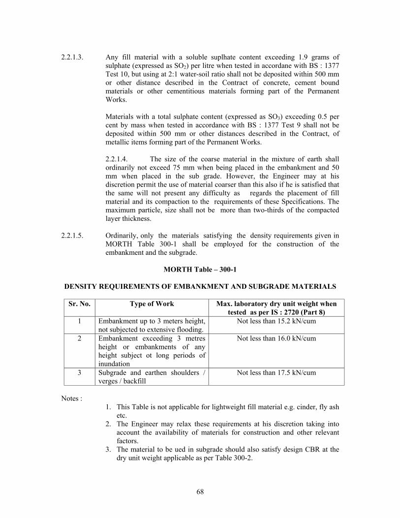
2.2.1.5. Ordinarily, only the materials satisfying the density requirements given in
MORTH Table 300-1 shall be employed for the construction of the embankment and the subgrade.
MORTH Table – 300-1
DENSITY REQUIREMENTS OF EMBANKMENT AND SUBGRADE MATERIALS
Sr. No. Type of Work Max. laboratory dry unit weight when
tested as per IS : 2720 (Part 8) 1 Embankment up to 3 meters height,
not subjected to extensive flooding. Not less than 15.2 kN/cum
2 Embankment exceeding 3 metres height or embankments of any height subject ot long periods of inundation
Not less than 16.0 kN/cum
3 Subgrade and earthen shoulders / verges / backfill
Not less than 17.5 kN/cum
Notes :
1. This Table is not applicable for lightweight fill material e.g. cinder, fly ash etc.
2. The Engineer may relax these requirements at his discretion taking into account the availability of materials for construction and other relevant factors.
3. The material to be ued in subgrade should also satisfy design CBR at the dry unit weight applicable as per Table 300-2.
69
2.2.2. General Requirements : 2.2.2.1 The materials for embankment shall be obtained from approved sources with
preference given to materials becoming available from nearby roadway excavation or any other excavation under the same contract.
The work shall be so planned and executed that the best available materials -are saved for the subgrade and the embankment portion just below the subgrade.
2.2.2.2. Borrow materials :
Where the materials are to be obtained from designated borrow areas, the location, size and shape of these areas shall be as indicated by the Engineer and the same shall not be opened without his written permission. Where specific borrow areas are not designated by the Employer/the Engineer, arrangement for locating the source of supply of material for embankment and subgrade as well as compliance to environmental requirements in respect of excavation and borrow areas as stipulated, from time to time by the Ministry of Environment and Forests, Government of India and the local bodies, as applicable, shall be the sole responsibility of the Contractor. Borrowpits along the road shall be discouraged. If permitted by the Engineer, these shall not be dug continuously. Ridges of not less than 8 m width should be left at intervals not exceeding 300 m. Small drains shall be cut through the ridges to facilitate drainage. The depth of the pits shall be so regulated that their bottom does not cut an imaginary line having a slope of I vertical to 4 horizontal projected from the edge of the final section of the bank, the maximum depth in any case being limited to 1.5 m. Also, no pit shall be dug within the offset width from the toe of the embankment required as per the consideration of stability with a minimum width of 10 m. Haulage of material to embankments or other areas of fill shall proceed only when sufficient spreading and compaction plant is operating at the place of deposition. No excavated acceptable material other than surplus to requirements of the Contract shall be removed from the site. Should the Contractor be permitted to remove acceptable material from the site to suit his operational procedure, then he shall make good any consequent deficit of material arising therefrom. Where the excavation reveals a combination of acceptable and unacceptable materials, the Contractor shall, unless otherwise agreed by the Engineer, carry out the excavation in such a manner that the acceptable materials are excavated separately for use in the permanent works without contamination by the unacceptable materials. The acceptable materials shall be stockpiled separately.

70
The Contractor shall ensure that he does not adversely affect the stability of excavation or fills by the methods of stockpiling materials, use of plants or siting of temporary buildings or structures. The Contractor shall obtain representative samples from each of the identified borrow areas and have these tested at the site laboratory following a testing programme approved by the Engineer. It shall be ensured that the subgrade material when compacted to the density requirements as in MORTH Table 300-2 shall yield the design CBR value of the subgrade
MORTH Table – 300-2
COMPACTION REQUIREMENTS FOR EMBANKMENT AND SUBGRADE
Sr. No. Type of Work Relative compation as percentage of
max. laboratory dry density as per IS : 2720 ( Part 8 )
1 Subgrade and earthen shoulders Not less than 97 2 Embankment Not less than 95 3 Expansive Clays
a) Subgrade and 500 mm portion just below the subgrade.
b) Remaining portion of
embankment
Not allowed
Not less than 90
The Contractor shall at least 7 working days before commencement of compaction submit the following to the Engineer for approval :
I The values of maximum dry density and optimum moisture content obtained
in accordance with IS : 2720 (Part : 7) or (Part 8) as the case may be, appropriate for each of the fill materials he intends to use.
II A graph of density plotted against moisture content from which each of the
values in (I) above of maximum dry density and optimum moisture content were determined.
III The Dry denisty-moisture content CBR relationships for light, intermediate
and heavy compactive efforts (light corresponding to IS : 2720 (Part 7), heavy corresponding to IS : 2720 (Part 8) and intermediate in-between the two) for each of the fill materials he inteds to use in the subgrade.
Once the above information has been approved by the Engineer, it shall form
the basis for compaction.

71
2.3. Construction Operations 2.3.1 Setting Out :
After the site has been cleared to MORTH Clause 201, the work shall be set out to MORTH Clause 301.3.1. The limits of embankment/subgrade shall be marked by Fixing batter pegs on both sides at regular intervals as guides before commencing the earthwork. The embankment/subgrade shall be built sufficiently wider than the design dimension so that surplus matenai may be trimmed, ensuring that the remaining material is to the desired density and in position specified and conforms to the specified side slopes.
2.3.2. Dewatering :
If the foundation of the embankment is in an area with stagnant water, and in the opinion of the Engineer it is feasible to remove it, the same shall be removed by bailing out or pumping, as directed by the Engineer and the area of the embankment foundation shall be kept dry. Care shall be taken to discharge the drained water so as not to cause damage to the works, crops or any other property. Due to any negligence on the part of the Contractor, if any such damage is caused, it shall be the sole responsibility of the Contractor to repair/restore it to original condition or compensate the damage at his own cost. If the embankment is to be constructed under water. Clause 3.4.6 shall apply.
2.3.3. Stripping and storing topsoil :
In localities where most of the available embankment materials are not conducive to plant growth, or when so directed by the Engineer, the topsoil from all areas of cutting and from all areas to be covered by embankment foundation shall be stripped to specified depths not exceeding 150 mm and stored in stockpiles of height not exceeding 2 m for covering embankment slopes, cut slopes and other disturbed areas where re-vegetation is desired. Topsoil shall not be unnecessarily trafficked either before stripping or. when in a stockpile. Stockpiles shall not be surcharged or otherwise loaded and multiple handling shall be kept to a minimum.
2.3.4. Compacting ground supporting embankment/subgrade:
Where necessary, the original ground shall be levelled to facilitate placement of first layer of embankment, scarified, mixed with water and then compacted by rolling so as to achieve minimum dry density as given in MORTH Table 300-2,

72
In case where the difference between the subgrade level (top of the subgrade on which pavement rests) and ground level is less than 0.5 m and the ground does not have 97 per cent relative compaction with respect to the dry density as given in MORTH Table 300-2, the ground shall be loosened upto a level 0.5 m below the subgrade level, watered and compacted in layers in accordance with Clauses 3.3.5 and 3.3.6 to not less than 97 per cent of dry density as given in MORTH Table 300-2. Where so directed by the Engineer, any unsuitable material occurring in the embankment foundation shall be removed and replaced by approved materials laid in layers to the required degree of compaction. Embankment or subgrade work shall not proceed until the foundations for embankment/subgrade have been inspected by the Engineer for satisfactory condition and approved.
Any foundation treatment specified for embankments especially high embankments, resting on suspect foundations as revealed by borehole logs shall be carried out in a manner and to the depth as desired by the Engineer. Where the ground on which an embankment is to be built has any of the material types (a) to (f) in Clause 3.2.1, at least 500 mm of such material must be removed and replaced by acceptable fill material before embankment construction commences.
2.3.5. Spreading material in layers and bringing to appropriate moisture
content
2.3.5.1. The embankment and subgrade material shall be spread in layers of uniform thickness not exceeding 200 mm compacted thickness over the entire width of embankment by mechanical means, finished by a motor grader and compacted as per Clause 3.3.6. The motor grader blade shall have hydraulic control suitable for initial adjustment and maintain the same so as to achieve the specific slope and grade. Successive layers shall not be placed until the layer under construction has been thoroughly compacted to the specified requirements as in MORTH Table 300-2 and got approved by the Engineer. Each compacted layer shall be finished parallel to the final cross-section of the embankment.
2.3.5.2. Moisture content of the material shall bechecked at the site of placement
prior to commencement of compaction; if found to be out of agreed limits, the same shall be made good. Where water is required to be added in such constructions, water shall be sprinkled from a water tanker fitted with sprinkler capable of applying water uniformly with a controllable rate of flow to variable widths of surface but without any flooding. The water shall be added uniformly and thoroughly mixed in soil by blading, discing or harrowing until a uniform moisture content is obtained throughout the depth of the layer.
73
If the material delivered to the roadbed is too wet, it shall be dried, by aeration and exposure to the sun, till the moisture content is acceptable for compaction. Should circumstances arise, where owing to wet weather, the moisture content cannot be reduced to the required amount by the above procedure, compaction work shall be suspended.
Moisture content of each layer of soil shall be checked in accordance with IS: 2720 (Part 2), and unless otherwise mentioned, shall be so adjusted, making due allowance for evaporation losses, that at the time of compaction it is in the range of I per cent above to 2 per cent below the optimum moisture content determined in accordance with IS:2720 (Part 7) or IS:2720 (Part 8) as the case may be. Expansive clays shall, however, be compacted at moisture content corresponding to the specified dry density, but on the wet side of the optimum moisture content obtained from the laboratory compaction curve. After adding the required amount of water, the soil shall be processed by means of graders, harrows, rotary mixers or as otherwise approved by the Engineer until the layer is uniformly wet.
Clods or hard lumps of earth shall be broken to have a maximum size of 75 mm when being placed in the embankment and a maximum size of 50 mm when being placed in the subgrade.
2.3.5.3. Embankment and other areas of fill shall, unless otherwise required in the
Contract or permitted by the Engineer, be constructed .evenly over their full width and their fullest possible extent and the Contractor shall control and direct construction plant and other vehicular traffic uniformly over them. Damage by construction plant and other vehicular traffic shall be made good by the Contractor with material having the same characteristics and strength as the material had before it was damaged.
Embankments and other areas of unsupported fills shall not be constructed with steeper side slopes, or to greater widths than those shown in the Contract, except to permit adequate compaction at the edges before trimming back, or to obtain the final profile following any settlement of the fill and the underlying material. Whenever fill is to be deposited against the face of a natural slope, or sloping earthworks face including embankments, cuttings, other fills and excavations steeper than I vertical on 4 horizontal, such faces shall be benched as per Clause 3.4.1 immediately before placing the subsequent fill. All permanent faces of side slopes of embankments and other areas of fill formed shall, subsequent to any trimming operations, be reworked and sealed to the satisfaction of the Engineer by tracking a tracked vehicle, considered suitable by the Engineer, on the slope or any other method approved by the Engineer.
2.3.6. Compaction

74
Only the compaction equipment approved by the Engineer shall be employed to compact the different material types encountered during construction. Smooth wheeled, vibratory, pneumatic tyred, sheepsfoot or pad foot rollers, etc. of suitable size and capacity as approved by the Engineer shall be used for the different types and grades of materials required to be compacted either individually or in suitable combinations. The compaction shall be done with the help of vibratory roller of 80 to 100 kN static weight with plain or pad foot drum or heavy pneumatic tyred roller of adequate capacity capable of achieving required compaction. The Contractor shall demonstrate the efficacy of the equipment he intends to use by carrying out compaction trials. The procedure to be adopted for these site trials shall first be submitted to the Engineer for approval.
Earthmoving plant shall not be accepted as compaction equipment nor shall the use of a lighter category of plant to provide any preliminary compaction to assist the use of heavier plant be taken into account.
Each layer of the material shall be thoroughly compacted to the densities specified in MORTH Table 300-2. Subsequent layers shall be placed only after the finished layer has been tested according to Clause E17.2.2 and accepted by the Engineer. The Engineer may permit measurement of field dry density bya nuclear moisture/density gauge used in accordance with agreed procedure and the gauge is calibrated to provide results identical to that obtained from tests in accordance with IS: 2720 (Part 28). A record of the same shall be maintained by the Contractor.
When density measurements reveal any soft areas in the embankment/subgrade/earthen shoulders, further compaction shall be carried out as directed by the Engineer. If inspite of that the specified compaction is not achieved, the material in the soft areas shall be removed and replaced by approved material, compacted to the density requirements and satisfaction of the Engineer.
2.3.7. Drainage
The surface of the embankment/subgrade at all times during construction shall be maintained at such a cross fall (not flatter than that required for effective drainage of an earthen surface) as will shed water and prevent ponding.
2.3.8. Repairing of damages caused by rain/spillage of water
The soil in the affected portion shall be removed in such areas as directed by the Engineer before next layer is laid and refilled in layers and compacted using appropriate mechanical means such as small vibratory roller, plate compactor or power rammer to achieve the required density in accordance with Clause 3.3.6. If the cut is not sufficiently wide for use of required
75
mechanical means for compaction, the same shall be widened suitably to permit their use for proper compaction. Tests shall be carried out as directed by the Engineer to ascertain the density requirements of the repaired area. The work of repairing the damages including widening of the cut, if any, shall be carried out by the Contractor at his own cost, including the arranging of machinery/equipment for the purpose.
2.3.9. Finishing operations
Finishing operations shall include the work of shaping and dressing the shoulders/verge/roadbed and side slopes to conform to the alignment, levels, cross-sections and dimensions shown on the drawings or as directed by the Engineer subject to .the surface tolerance described in Clause E16. Both the upper and lower ends of the side slopes shall be rounded off to improve appearance and to merge the embankment with the adjacent terrain. The topsoil, removed and conserved earlier (MORTH Clause 301.3.2 and 3.3.3) shall be spread over the fill slopes as per directions of the Engineer to facilitate the growth of vegetation. Slopes, shall be roughened and moistened slightly prior to the application of the topsoil in order to provide satisfactory bond. The depth of the topsoil shall be sufficient to sustain plant growth, the usual thickness being from 75 mm to 150 mm.
Where directed, the slopes shall be turfed with sods in accordance with MORTH Clause 307. If seeding and mulching of slopes is prescribed, this shall be done to the requirement of MORTH Clause 308. When earthwork operations have been substantially completed, the road area shall be cleared of all debris, and ugly scars in the construction area responsible for objectionable appearance eliminated.
2.4. Construction of Embankment and Subgrade under Special Conditions 2.4.1. Earthwork for widening existing road embankment When an existing
embankment and/or subgrade is to be widened and its slopes are steeper than I vertical on 4 horizontal, continuous horizontal benches, each at least 300 mm wide, shall be cut into the old slope for ensuring adequate bond with the fresh embankment/subgrade material to be added. The material obtained from cutting of benches could be utilized in the widening of the embankment/subgrade. However, when the existing slope against which the fresh material is to be placed is flatter than 1 vertical on 4 horizontal, the slope surface may only be ploughed or scarified instead of resorting to benching.
Where the width of the widened portions is insufficient to permit the use of conventional rollers, compaction shall be carried out with the help of small vibratory rollers/plate compactors/power rammers or any other appropriate equipment approved by the Engineer. End dumping of material from trucks for widening operations shall be avoided except in difficult circumstances when

76
the extra width is too narrow to permit the movement of any other types of hauling equipment.
2.4.2. Earthwork for embankment and subgrade to be placed against sloping
ground :
Where an embankment/subgrade is to be placed against sloping ground, the latter shall be appropriately benched or ploughed/scarified as required in Clause 3.4.1 before placing the embankment/subgrade material. Extra earthwork involved in benching or due to ploughing/scarifying etc. shall be considered incidental to the work. For wet conditions, benches with slightly inward fall and subsoil drains at the lowest point shall be provided as per the drawings, before the fill is placed against sloping ground. Where the Contract requires construction of transverse subsurface drain at the cut-fill interface, work on the same shall be carried out to MORTH Clause 309 in proper sequence with the embankment and subgrade work as approved by the Engineer.
2.4.3. Earthwork over existing road surface :
Where the embankment is to be placed over an existing road surface, the work shall be carried out as indicated below :
1. If the existing road surface is of granular or bituminous type and lies within 1
m of the new subgrade level, the same shall be scarified to a depth of 50 mm or more if specified, so as to provide ample bond between the old and new material ensuring that at least 500 mm portion below the top of new subgrade level is compacted to the desired density.
2. If the existing road surface is of cement concrete type and lies within 1
m of the new subgrade level the same shall be removed completely. 3. If the level difference between the existing road surface and the new
formation level is more than 1m, the existing surface shall be permitted to stay in place without any modification.
2.4.4 Embankment and subgrade around structures
To avoid interference with the construction of abutments, wing walls or return walls of culvert/bridge structures, the Contractor shall, at points to be determined by the Engineer suspend work on embankment forming approaches to such structures, until such time as the construction of the latter is sufficiently advanced to permit the completion of approaches without the risk of damage to the structure.

77
Unless directed otherwise, the filling around culverts, bridges and other structures upto a distance of twice the height of the road from the back of the abutment shall be carried out independent of the work on the main embankment. The fill material shall not be placed against any abutment or wing wall, unless permission has been given by the Engineer but in any case not until the concrete or masonry has been in position for 14 days. The embankment and subgrade shall be brought up simultaneously in equal layers on each side of the structure to avoid displacement and unequal pressure. The sequence of work in this regard shall be got approved from the' Engineer.
The material used for backfill shall not be an organic soil or highly plastic clay having plasticity index and liquid limit more than 20 and 40 respectively when tested according to IS:2720 (Part 5). Filling behind abutments and wing walls for all structures shall conform to the general guidelines given in Appendix 6 of IRC:78 (Standard Specifications and Code of Practice for Road Bridges-Section VII) in respect of the type of material, the extent of backfill, its laying and compaction etc. The fill material shall be deposited in horizontal layers in loose thickness and compacted thoroughly to the requirements of MORTH Table 300-2. Where the provision of any filter medium is specified behind the abutment, the same shall be laid in layers simultaneously with the laying of fill material. The material used for filter shall conform to the requirements for filter medium spelt out in MORTH Clause 2502/309.3.2 (B) unless otherwise specified in the Contract.
Where it may be impracticable to use conventional rollers, the compaction shall be carried out by appropriate mechanical means such as small vibratory roller, plate compactor or power rammer. Care shall be taken to see that the compaction equipment does not hit or come too close to any structural member so as to cause any damage to them or excessive pressure against the structure.
2.4.5. Construction of embankment over ground incapable of supporting
construction equipment :
Where embankment is to be constructed across ground which will not support the weight of repeated heavy loads of construction equipment, the first layer of the fill may be constructed by placing successive loads of material in a uniformly distributed layer of a minimum thickness required to support the construction equipment as permitted by the Engineer. The Contractor, if so desired by him, may also use suitable geosynthetic material to increase the bearing capacity of the foundation. This exception to normal procedure will not be permitted where, in the opinion of the Engineer, the embankments could be constructed in the approved manner over such ground by the use of lighter or modified equipment after proper ditching and drainage have been provided. Where this exception is permitted, the selection of the material and the construction procedure to obtain an acceptable layer shall be the responsibility of the Contractor. The cost of providing suitable traffic conditions for construction equipment over any area of the Contract

78
will be the responsibility of the Contractor and no extra payment will be made to him. The remainder of the embankment shall be constructed as specified in Clause 3.3.
2.4.6. Embankment construction under water :
Where filling or backfilling is to be placed under water, only acceptable granular material or rock shall be used unless otherwise approved by the Engineer. Acceptable granular material shall consist of graded, hard durable particles with maximum particle size not exceeding 75 mm. The material should be non-plastic having uniformity coefficient of not less than 10. The material placed in open water shall be deposited by end tipping without compaction.
2.4.7. Earthwork for high embankment :
In the case of high embankments, the Contractor shall normally use the material from the specified borrow area. In case he desires to use different material for his own convenience, he shall have to carry out necessary soil investigations and redesign the high embankment at his own cost. The Contractor shall then furnish the soil test data and design of high embankment for approval of the Engineer, who reserves the right to accept or reject it.
If necessary, stage construction of fills and any controlled rates of filling shall be carried out in accordance with the Contract including installation of instruments and its monitoring. Where required, the Contractor shall surcharge embankments or other areas of fill with approved material for the periods specified in the Contract. If settlement of surcharged fill . results in any surcharging material, which is unacceptable for use in the Fill being surcharged, lying below formation level, the Contractor shall remove the unacceptable material and dispose it as per direction of the Engineer. He shall then bring the resultant level up to formation level with acceptable material.
2.4.8. Settlement period :
Where settlement period is specified in the Contract, the embankment shall remain in place for the required settlement period before excavating for abutment) wingwall, retaining wall, footings, etc., or driving foundation piles. The duration of the required settlement period at each location shall be as provided for in the Contract or as directed by the Engineer.
2.5. Plying of Traffic
Construction and other vehicular traffic shall not use the prepared surface of the embankment and/or subgrade without the prior permission of the Engineer. Any damage arising out of such use shall, however, be made good by the Contractor at his own expense as directed by the Engineer.

79
2.6. Surface Finish and Quality Control of Work
The surface finish of construction of subgrade shall conform to the requirements of Clause E16. Control on the quality of materials and works shall be exercised in accordance with Clause E17.
2.7. Subgrade Strength 2.7.1. It shall be ensured prior to actual execution that the borrow area material to be
used in the subgrade satisfies the requirements of design CBR. 2.7.2. Subgrade shall be compacted and finished to the design strength consistent
with other physical requirements. The actual laboratory CBR values of constructed subgrade shall be determined on undisturbed samples cut out from the compacted subgrade in CBR mould fitted with cutting shoe or on remoulded samples, compacted to the field density at the Field moisture content.
2.8. Measurements for Payment
Earth embankment/subgrade construction shall be measured separately by taking cross sections at intervals in the original position before the work starts and after its completion and computing the volumes of earthwork in cubic metres by the method of average end areas.
The measurement of fill material from borrow areas shall be the difference between the net quantities of compacted Fill and the net quantities of suitable material brought from roadway and drainage excavation. For this purpose, it shall be assumed that one cu.m. of suitable material brought to site from road and drainage excavation forms one cu.m. of compacted fill and all bulking or shrinkage shall be ignored.
Construction of embankment under water shall be measured in Cu.m. Construction of high embankment with specified material and in specified manner shall be measured in cu.m. Stripping including storing and reapplication of topsoil shall be measured in cu.m. Work involving loosening and recompacting of ground supporting embankment/subgrade shall be measured in cu. m.
Removal of unsuitable material at embankment/subgrade foundation and replacement with suitable material shall be measured in cu.m.

80
Scarifying existing granular/bituminous- road surface shall be measured in square metres. Dismantling and removal of existing cement concrete pavement shall be measured vide MORTH Clause 202.6. Filter medium and backfill material behind abutments, wing walls and other retaining structures shall be measured as Finished work in position in cu.m.
2.9. Rates 2.9.1. The Contract unit rates for the items of embankment and subgrade
construction shall be paid in full for carrying out the required operations including full compensation for :
i. Cost of arrangement of land as a source of supply of material of
required quantity for construction unless provided otherwise in the Contract; ii. Setting out; iii. Compacting ground supporting embankment/subgrade except where removal
and replacement of unsuitable material or loosening and recompacting is involved,
iv. Scarifying or cutting continuous horizontal benches 300 mm wide on side
slopes of existing embankment and subgrade as applicable; v. Cost of watering or drying of material in borrow areas and/or embankment
and subgrade during construction as required;
vi. Spreading in layers, bringing to appropriate moisture content and compacting to Specification requirements;
vii. Shaping and dressing top and slopes of the embankment and subgrade
including rounding of corners, viii. Restricted working at sites of structures; ix. Working on narrow width of embankment and subgrade; x. Excavation in all soils from borrow pits/designated borrow areas including
clearing and grubbing and transporting the material to embankment and subgrade site with all lifts and leads unless otherwise provided for in the Contract;
xi. All labour, materials, tools, equipment and incidentals necessary to complete
the work to the Specifications; xii. Dewatering; and

81
xiii. Keeping the embankment/completed formation free of water as per MORTH
Clause 311. 2.9.2. In case the Contract unit rate specified is not inclusive of all leads, the unit
rate for transporting material beyond the initial lead, as specified in the Contract for construction of embankment and subgrade shall ..be inclusive of full compensation for all labour, equipment, tools and incidentals necessary on account of the additional haul or transportation involved beyond the specified initial lead.
2.9.3. MORTH Clause 301.9.5 shall apply as regards Contract unit rates for items of
stripping and storing top soil and of reapplication of topsoil. 3.9.4. Clause 301.9.2 shall apply as regards Contract unit rate for the item of loosening and recompacting the embankment/subgrade foundation.
2.9.4. MORTH Clauses 301.9.1 and 3.8 shall apply as regards Contract rates for items of removal of unsuitable material and replacement with suitable material respectively.
2.9.5. The Contract unit rate for scarifying existing granular/bituminous road surface shall be payment in full for carrying out the required operations including full compensation for ail labour, materials, tools, equipment and incidentals necessary to complete the work. This will also comprise of handling, salvaging, stacking and disposing of the dismantled materials within all lifts and upto a lead of 1000 m or as otherwise specified.
2.9.6. MORTH Clause 202.7 shall apply as regards Contract unit rate for dismantling and removal of existing cement concrete pavement.
2.9.7. The Contract unit rate for providing and laying filter material behind
abutments shall be payment in full for carrying out the required operations including all materials, labour, tools, equipment and incidentals to complete the work to Specifications.
2.9.8. Clause 3.4.6 shall apply as regards Contract unit rate for construction of
embankment under water. 2.9.9. Clause 3.4.7 shall apply as regards Contract unit rate for construction of high
embankment. It shall include cost of instrumentation, its monitoring and settlement period, where specified in the Contract or directed by the Engineer.

82
Item No. 3 Box cutting the road surface to proper slope and camber for making abase of road work including removing the excavated stuff and disposing on road or side slope as directed upto 50 mt lead etc. complete as per technical specification MORTH clause 301.
3 EXCAVATION FOR ROADWAY AND DRAINS 3.1 Scope
This work shall consist of excavation, removal and satisfactory disposal of all materials necessary for the construction of roadway, side drains and waterways in accordance with requirements of these Specifications and the lines, grades and cross-sections shown in the drawings or as indicated by the Engineer. It shall include the hauling and stacking of or hauling to sites of embankment and subgrade construction, suitable cut materials as required, as also the disposal of unsuitable cut materials in specified manner, trimming and finishing of the road to specified dimensions or as directed by the Engineer.
3.2 Classification of Excavated Material 3.2.1 Classification :
All materials involved in excavation shall be classified by the Engineer in the following manner :
(a) Soil
This shall comprise topsoil, turf, sand, silt, loam, clay, mud, peat, black cotton soil, soft shale or loose moorum, a mixture, a mixture of these and similar material which yields to the ordinary application of pick, spade and or shovel, rake or other ordinary digging implement. Removal of grade orany other nodular material having dimension in any one direction not exceeding 75 mm occurring in such strata shall be deemed to be covered under this category.
(b) Ordinary Rock (not requireing blasting) This shall include :
(i) rockt ypes such as laterites, shales and conglomerates, varieties of limestone and sandstone etc., which may be quarrried or split with crow bars, also including any rock which in dry state may be hard, requiring blasting but which, when wet, becomes soft and manageable by means other than blasting:
(ii) macadam surfaces such as water bound and bitumen/tar bound; soling of roads paths etc and hard core; compact moorum or stabilised soil requiring grafting tool or pick or both and shovel, closely applied; gravel and cobble stone having maximum dimension in any one direction between 75 and 30 mm.
(iii) lime concrete, stone masonry in lime mortar and brick work in lime/cement mortar below ground level, reinforced cement concrete which may be broken up with crow bars or picks and stone masonry in cement mortar below ground level; and

83
(iv) boulders which do not require blasting having miximum dimension in any direction of more than 300 mm found lying loose on the surface or embeded in river be, soil, talus, slope wash and terrace material of dissimilar origin.
(c) Hard Rock ( Requiring Blasting )
This shall comprise :
(i) any rock or cement concrete for the excavation of which the use of mechanical plant and/ or blasting is required;
(ii) reinforced cement concrete (reinforcement cut through but not separated from the concrete) below ground level; and
(iii) boulders requiring blasting.
(d) Hard Rock (blasting prohibited) Hard rock requiring blasting as described under (c) but where blasting is prohibited for any reason and excavation has to be carried out by chiselling, wedging or any other agreed method.
(e) Marshy Soil
This shall include soils like soft clays and peats excavated below the orginal ground level of marshes and swamps and soils excavated from other areas requiring continuous pumping or bailing out of water.
3.2.2 Authority for Classification : The classification ofexcavation shall be decided by the Enginer and his decision shall be final
and binding on the Contractor. Merely the use of explosives in excavation will not be considedred as a reason for higher classification unless blasting is clearly necessary in the opinion of the Engineer.
3.3 Construction Operations 3.3.1 Setting Out : After the site has been cleared as per MORTH clause 201, the limits of excavation shall be
set out true to lines, curves, slopes grades andsections as shown on the drawings or as directed by the Engineer. The Contractor shall provide all labour survey instruments and materials such as strings, pegs , nails, bamboos, stones, lime, mortar, concrete etc., required in connection with the setting out of works and theestablishement of bench marks. The Contractor shall beresponsible for the maintencance of bench marks and other marks and stakes as longas in the opinion of the Engineer, they are required for the work.
3.3.2 Stripping and storing topsoil : When so directed by the Engineer, the topsoil existing over the sites of excavation shall be
stripped to specifieddepths constituting Horizon “A” and stockpiled at designated locations for re-use in covering embankment slopes, cut slopes,
84
berms and other disturbed areas where re-vegetation is desired. Prior to stipping the topsoil, all trees, shrubs etc shall beremved along with therir roots, with approval of the Engineer.
3.3.3 Excavation – General
All excavations shall be carried out in conformity with the direction laid here-in-under and in a manner approved by the Engineer. The work shall be so done that the suitable materials available from excavation are satisfactorily utilized as decided upon beforehand. While planning or executing excavations, the Contractor shall take all adequate precautions against soil erosion, water pollution etc. as per MORTH Clause 306, and take appropriate drainage measures to keep the site free of water in accordance with MORTH Clause 311. The excavations shall conform to the lines, grades, side slopes and levels shown on the drawings or as directed by the Engineer. The Contractor shall not excavate outside the limits of excavation. Subject to the permitted tolerances, any excess depth/ width excavated beyond the specified levels/dimensions on the drawings shall be made good at the cost of the Contractor with suitable material of characteristics similar to that removed and compacted to the requirements of MORTH Clause 305. All debris and loose material on the slopes of cuttings shall be removed. No backfilling shall be allowed to obtain required slopes excepting that when boulders or soft materials are encountered in cut slopes, these shall be excavated to approved depth on instructions of the Engineer and the resulting cavities filled with suitable material and thoroughly compacted in an approved manner. After excavation, the sides of excavated area shall be trimmed and the area contoured to minimise erosion and ponding, allowing for natural drainage to take place. If trees were removed, new trees shall be planted, as directed by the Engineer. The cost .of planting new trees shall be deemed to be incidental to the work.
3.3.4. Methods, tools and equipment :
Only such methods, tools and equipment as approved by the Engineer shall be adopted/used in the work. If so desired by the Engineer, the Contractor shall demonstrate the efficacy of the type of equipment to be used before the commencement of work.
3.3.5. Marsh Excavation :
The excavation of soils from marshes/ swamps shall be carried out as per the programme approved by the Engineer.

85
Excavation of marshes shall begin at one end and proceed in one direction across the entire marsh immediately ahead of backfilling. The method and sequence of excavating and backfilling shall be such as to ensure, to the extent practicable, the complete removal or displacement of all muck from within the lateral limits called for on the drawings or as staked by the Engineer, and to the bottom of the marsh, Firm support or levels indicated.
3.3.6. Excavation of road shoulders/verge/median for widening of pavement or providing treated shoulders :
In works involving widening of existing pavements or providing treated shoulders, unless otherwise specified, the shoulder/verge/median shall be removed to their full width and to levels shown on drawings or as indicated by the Engineer. While doing so, care shall be taken to see that no portion of the existing pavement designated for retention is loosened or disturbed. If the existing pavement gets disturbed or loosened, it shall be dismantled and cut to a regular shape with -sides vertical and the disturbed/loosened portion removed completely and relaid as directed by the Engineer, at the cost of the Contractor:
3.3.7 Excavation for surface/sub-surface drains :
Where the Contract provides for construction of surface/sub-surface drains to MORTH Clause 309, excavation for these shall be carried out in proper sequence with other works as approved by the Engineer.
3.3.8 Sides
If slips, slides, over-breaks or subsidence occur in cuttings during the process of construction, they shall be removed at the cost of the Contractor as ordered by the Engineer. Adequate precautions shall be taken to ensure that during construction, the slopes are not rendered unstable or give rise to recurrent slides after construction. If Finished slopes slide into the roadway subsequently, such slides shall be removed and paid for at the Contract rate for the class of excavation involved, provided the slides are not due to any negligence on the part of the Contractor. The classification of the debris material from the slips, slides etc. shall conform to its condition at the time of removal and payment made accordingly regardless of its condition earlier.
3.3.9 Dewatering :
If water is met with in the excavations due to springs, seepage, rain or other causes, it shall be removed by suitable diversions, pumping or bailing out and the excavation kept dry whenever so required or directed by the Engineer. Care shall be taken to discharge the drained water into suitable outlets as not to cause damage to the works, crops or any other property. Due to any negligence on the part of the Contractor, if any such damage is caused, it shall be the sole responsibility of the Contractor to repair/restore to the original condition at his own cost or compensate for the damage.

86
3.3.10. Disposal of excavated materials :
All the excavated materials shall be the property of the Employer, The material obtained from the excavation of roadway, shoulders, verges, drains, cross drainage works etc., shall be used for filling up of (i) roadway embankment, (ii) the existing pits in the right-of-way and (iii) for landscaping of the road as directed by the Engineer, including levelling and spreading with all lifts and lead upto 50 m and no extra payment shall be made for the same. All hard materials, such as hard moorum, rubble, etc., not intended for use as above shall be stacked neatly on specified land as directed by the Engineer with all lifts and lead upto 50m. Unsuitable and surplus material not intended for use within the lead specified above shall also, if necessary, be transported with all lifts and lead beyond initial 50 m, disposed of or used as directed by the Engineer.
3.3.11. Backfilling : Backfilling of masonry /concrete/hume pipe drain excavation shall be done with approved material after concrete/ masonry/hume pipe is fully set and carried out in such a way as not to cause undue thrust on any part of the structure and/or not to cause differential settlement All space between the drain walls and the side of the excavation shall be refilled to the original surface making due allowance for settlement, in layers generally not exceeding 150 mm compacted thickness to the required density, using suitable compaction equipment such as mechanical tamper, rammer or plate compactor as directed by the Engineer.
3.4. Plying of Construction Traffic
Construction traffic shall not use the cut formation and finished subgrade without the prior permission of the Engineer. Any damage arising out of such use shall be made good by the Contractor at his own expense.
3.5. Preservation of Property
The Contractor shall undertake all reasonable precautions for the protection and preservation of any or all existing roadside trees, drains, sewers or other sub-surface drains, pipes, conduits and any other structures under or above ground, which may be affected by construction operations and which, in the opinion of the Engineer, shall be continued in use without any change. Safety measures taken by the Contractor in this respect, shall, be got approved from the Engineer. However, if any of these objects is damaged by reason of the Contractor's negligence, it shall be replaced or restored to the original condition at his expense. If the Contractor fails to do so, within the required time as directed by the Engineer or if, in the opinion of the Engineer, the actions initiated by 'the Contractor to replace/restore the damaged objects are not satisfactory, the Engineer shall arrange the replacement/

87
restoration directly through any other agency at the risk and cost of the Contractor after issuing a prior notice to the effect.
3.6. Preparation of Cut Formation
The cut formation, which serves as a subgrade, shall be prepared to receive the sub-base/base course as directed by the Engineer. Where the material in the subgrade (that is within 500 mm from the lowest level of the pavement) has a density less than specified in Table 300-2, the same shall be loosened to a depth of 500 mm and compacted in layers in accordance with the requirements of MORTH Clause 305. Any unsuitable material encountered in the subgrade level shall be removed as directed by the Engineer and replaced with Suitable material compacted in accordance with MORTH Clause 305. In rocky formations, the surface irregularities shall be corrected and the levels brought up to the specified elevation with granular base material as directed by the Engineer, laid and compacted in accordance with the respective Specifications for these materials. The unsuitable material shall be disposed of in accordance with Clause 4.3.11. After satisfying the density requirements, the cut formation shall be prepared to receive the subbase/base course in accordance with MORTH Clauses 310 and 311 to receive the sub-base/base course.
3.7. Finishing Operations
Finishing operations shall include the work of properly shaping and dressing all excavated surfaces.
When completed, no point on the slopes shall vary from the designated slopes by more than 150 mm measured at right angles to the slope, except where excavation is in rock (hard or soft) where no point shall vary more than 300 mm from the designated slope. In no case shall any portion of the slope encroach on the roadway. The finished cut formation shall satisfy the surface tolerances described in Clause E16. Where directed, the tops oil removed earlier and conserved (Clauses 4.3.2 and MORTH Clause 305.3.3) shall be spread over cut slopes, where feasible, berms and other disturbed areas. Slopes may be roughened and moistened slightly, prior to the application of topsoil, in order to provide satisfactory bond. The depth of topsoil shall be sufficient to sustain plant growth, the usual thickness being from 75 mm-to 100 mm.

88
3.8. Measurements for Payment
Excavation for roadway shall be measured by taking cross-sections at suitable intervals in the original, position .before the work starts and after its completion and computing the volumes in cu. m. by the method of average end areas for each class of material encountered. Where it is not feasible to compute volumes by this method because of erratic location of isolated deposits, the volumes shall be computed by other accepted methods.
At the option of the Engineer, the Contractor shall leave depth indicators during excavations of such shape and size and in such Positions as directed so as to indicate the original ground level as accurately as possible. The contractor shall see that these remain intact till the final measurements are taken. For rock excavation, the overburden shall be removed first so that necessary cross-sections could be taken for measurement. Where cross section measurements could not be taken due to irregular configuration or where the rock is admixed with other classes of materials, the volumes shall be computed on the basis of stacks of excavated rubble after making 35 per cent deduction therefrom. When volumes are calculated in this manner for excavated material other than rock, deduction will be to the extent of 16 per cent of stacked volumes. Works involved in the preparation of cut formation shall be measured in units indicated below :
(i) Loosening and recompacting the loosened material at
subgrade Sq.m.
(ii) Loosening and removal of unsuitable material and replacing with a suitable material and compacting to required density
Sq.m.
(iii) Preparing rocky subgrade Sq.m (iv) Stripping including storing and reapplication of topsoil Cum (v) Disposal of surplus material beyond initial 1000 m lead Cum
3.9 Rates 3.9.1.1 The Contract unit rates for the items of roadway and drain excavation shall be
payment in full for carrying out the operations required for the individual items including full compensation for :
(i) Setting out ; (ii) Transporting the excavated materials and depositing the same on sites of
embankments, spoil banks or stacking as directed within all lifts and lead upto 1000 m or as otherwise specified;
(iii) Trimming bottoms and slopes of excavation; (iv) Dewatering; (v) Keeping the work free of water as per MORTH Clause 311; and

89
(vi) All labour, materials, tools, equipment, safety measures, testing and incidentals necessary to complete the work to Specifications.
Provided however where presplitting is prescribed to achieve a specified slope in rock excavation, the same shall be paid for vide MORTH Clause 303.5.
3.9.1.2 The Contract unit rate for loosening and recompacting the loosened materials
at subgrade shall include full compensation for loosening to the specified depth, including breaking clods, spreading in layers, watering where necessary and compacting to the requirements.
3.9.1.3 Clause 4.9.1 and MORTH Clause 305.8 shall apply as regards Contract unit
rate for item of removal of unsuitable material and replacement with suitable material respectively.
3.9.1.4 The Contract unit rate for item of preparing rocky subgrade as per Clause 4.6
shall be full compensation for providing, laying and compacting granular base material for correcting surface irregularities including all materials, labour and incidentals necessary to complete the work and all leads and lifts.
3.9.1.5 The Contract unit rate for the items of stripping and storing topsoil and of
reapplication of topsoil shall include full compensation for all the necessary operations including all lifts, but leads upto 1000 m.
3.9.1.6 The Contract unit rate for disposal of Surplus earth from roadway and drain
excavation shall be full compensation for all labour, equipment, tools and incidentals necessary on account of the additional haul or transportation involved beyond the initial lead of 1000 m.

90
306 Item No. 4 Collecting, carting and stacking Coarse sand ( CBR not less then 10 %) at site of work etc. complete.
307 4.1 Scope
This work shall consist of collecting carting & stacking coarse sand at site of work as directed by Engineer In charge.
4.2 Material. The material to used for the work shall be natural sharp clean graded sand ( CBR not less than 10 %).
4.2.1 The material should be free from organic or other deuterious constituents & confirm the grading have given in Table 1000-2.
4.2.2 The material for the purpose shall be of approved quality. Any materials,
which are found inferior, shall be rejected and the contractor shall remove such rejected materials from the site at his own cost. The material shall be approved by the Executive Engineer or his authorised agent.
4.2.3 River or nala or sea sand required for the work shall be clear , sound,
properly, graded, free from organic materials silt clay etc. and shall be got approved by the Engineer in charge. The sand shall be well graded.
4.3 Measurement for payment
The item shall be measured in cubic meter for the complete item of work. Stacking shall be done by filling standard size boxes of 2mt. x 1.5mt. x 0.5mt. size. No deduction shall be made for voids from the grade measurements.
4.4 Rate
The contract unit rate for collecting carting of stacking of coarse sand including all materials labour tools. Equipments for construction and other incidental cost necessary to complete the work.

91
308 Item No. 5 Collecting, carting and stacking stone dust at site of work etc. complete.
309 5.1 Scope
This work shall consist of collecting carting & stacking stone dust at site of work as directed by Engineer In charge.
5.2 Material. 5.2.1 The material to be used for the work shall be free from organic impurities &
have a plasticity index not grater than 6 . 5.2.2 The material should be graded within the limit indicated the Table 500-9.
Is Sieve(mm) Cumulative percent passing 0.6 100 0.3 95-100
0.075 85-100 5.3 Measurement for payment
The item shall be measured in cubic meter for the complete item of work. Stacking shall be done by filling standard size boxes of 2mt. x 1.5mt. x 0.5mt. size. No deduction shall be made for voids from the grade measurements.
5.4 Rate
The contract unit rate for collecting carting of stacking of stone dust including all materials labour tools. Equipments for construction and other incidental cost necessary to complete the work.

92
310 Item No. 6 Collecting, carting and stacking machined crushed B.T. metal 25mm 90mm size at site of work etc. complete.
311 6.1 Scope
This work shall consist of collecting carting & stacking machine crused BT metal. Size 45mm to 90mm at site of work as directed by Engineer In charge.
6.2 Material. 6.2.1 Thefield of M.C.B.T. Metal shall be of approved quarry as shown on the
quarry chart as well as approved by the Executive Engineer prior to collection. 6.2.2 The M.C.B.T. metal shall be hard, tough,, sound, durable, black trap field
metal of close texture, free from decay and weathering. Each piece of the stone shall be angular and roughly cubical in shape and round elongated or flaky material shall be rejected. No round or oblong pebblesor angular chips larger or smaller than specified size shall be allowed.
6.2.3 All unsound weathered or disintegrated stone obtained from the upper surface
layer of the quarry or other layer of boulders shall be rejected. The physical requirement for standard size metall shall conform to the test results indicated in given table.
Test Test Method Requirement (a) Los Angeles
Abrasion Value Aggregate impact value
(b) Flakiness Index
IS 2386 Part IV IS 2386 Part IV or Is 5640 IS 2386 Part I
50 % (maximum) 40% (Maximum) 15% (maximum)
6.2.4 The M.C.B.T. metal shall be as nearly uniform in size as possible and shall
confirm to following minimum requirements of passing through the rings.. 6.2.5 wherever and doubt exists as to whether the above requirement are satisfied in
whole or part. The contractor shall be screened the collection of M.C.B.T. metal if so ordered by the Executive Engineer and for which no extra payments shall be claimed by the contractor.
6.2.6 Any collection which does not fully satisfy the above requirements is liable to be rejected altogether.

93
6.3 Measurement for payments.
The item shall be measured in cubic meter for the complete item of work as directed by Engineer Incharge. Stacking shall be done by filling standard size boxes of 2mt. x 1.5mt. x 0.5mt. size. No deduction shall be made for voids from the grade measurements.
6.4 Rate
The contract unit rate for collecting carting & stacking of (45-90) B.T. metal including all material labour tools equipments for construction & other incidental cost necessary to complete the work.

94
312 Item No. 7 Spreading the stone aggregates for soling and W.B.M. in two layers each of 100mm including filling the interstice forming the surface to required grade and camber.
313 7.1 Scope 314 This work shall consist of spreading the stone aggregates for soling and
W.B.M. in two layers each of 100mm including filling the interstice forming the surface to required grade and camber.
7.2 Construction Operation
The sub-base material of grading specified in the Contract shall be spread on the prepared sub grade as approved by the Engineer. When the sub-base material consists of combination of materials mentioned in MORTH Clause 401.2.1, mixing shall be done mechanically by the mix-in-place method. Manual mixing shall be permitted only where the width of laying is not adequate for mechanical operations as in small-sized jobs. The equipment used for mix-in-place construction shall be a rotavator or similar approved equipment capable of mixing the material to the desired degree. If so desired by the Engineer, trial runs with the equipment shall be carried out to establish its suitability for the work. Moisture content of the loose material shall be checked in accordance with IS : 2720 (Part 2) and suitably adjusted by sprinkling additional water from a truck mounted or trailer mounted water tank and suitable for applying water uniformly and a controlled quantities to variable widths of surface or other means approved by the Engineer so that, at the time of compaction, it is from 1 percent above to 2 percent below the optimum moisture content corresponding to IS : 2720 (Part 8). While adding water, due allowance shall be made for evaporation losses, After water has been added, the material shall be processed by mechanical or other approved means like disc harrows, rotavators until the layer is uniformly wet.
7.3 Measurement for payments.
The item shall be measured in cubic meter for the complete item of work as directed by Engineer Incharge.
7.4 Rate
The contract unit rate for Spreading the stone aggregates for soling and W.B.M. in two layers each of 100mm including filling the interstice forming the surface to required grade and camber including all material labour tools equipments for construction & other incidental cost necessary to complete the work.

95
315 Item No. 8 Spreading the blindage of road crust filling the gaps in metal and leveling to camber and gradient.
316 8.1 Scope 317 This work shall consist of Spreading the blindage of road crust filling the gaps
in metal and leveling to camber and gradient.
7.3 Construction Operation 7.3.1 Spreading of material shall be started after the full supply in particular K M is
collected., measured and recorded in the measurement books. Permission of the Engineering in charge shall be obtained before spreading.
7.3.2 It shall be seen that the formation is dressed to the required camber and grade.
If the blindage is to be spread over the metaled surface then the spreading shall be uniform and as its has to act as binding surface it shall be used for filling the interstices of metal and forming a smooth running surface as far as possible.
8.3 Measurement for payments.
The item shall be measured in cubic meter for the complete item of work as directed by Engineer Incharge.
8.4 Rate The contract unit rate for collecting carting & stacking of (45-90) B.T. metal
including all material labour tools equipments for construction & other incidental cost necessary to complete the work.

96
318 Item No. 9 Rolling and consolidation water bound macadam (except
laterite and kanker) including watering not exceeding 150mm thickness in layers including binding materials including filling in dipression which occures during the process (B) with Vibratory road roller exceeding 8 tonnes and not exceeding 12 tonnes.
319 9.1 Scope 320 This work shall consist Rolling and consolidation water bound macadam
(except laterite and kanker) including watering not exceeding 150mm thickness in layers including binding materials including filling in dipression which occures during the process (B) with Vibratory road roller exceeding 8 tonnes and not exceeding 12 tonnes.
7.4 Construction Operation
Rolling shall be carried out by vibratory roller of 8 to 12 tonnes capacity. Rolling shall commence at the lower edge and proceed towards the upper edge longitudinally for portions having unidirectional crossfall and super elevation and shall commence at the edges and progress towards the centre for portions having crossfall on both sides. Each pass of the roller shall uniformly overlap not less than one-third of the track made in the preceding pass. During rolling, the grade and crossfall (camber) shall be checked and any high spots or depressions, which become apparent, corrected by removing or adding fresh material. The speed of the roller shall not exceed 5 km per hour. Rolling shall be continued till the density achieved is at least 98 percent of the maximum dry density for the material determined as per IS : 2720 (Part 8). The surface of any layer of material on completion of compaction shall be well closed, free from movement under compaction equipment and from compaction planes, ridges, cracks or loose material. All those, segregated or otherwise defective areas shall be made good to the full thickness of layer and re-compacted.
9.3 Measurement for payments.
The item shall be measured in Smt for the complete item of work as directed by Engineer Incharge.
9.4 Rate 321 The contract unit rate for Rolling and consolidation
water bound macadam (except laterite and kanker) including watering not exceeding 150mm thickness in layers including binding materials including filling in dipression which occures during the process (B) with Vibratory road roller exceeding 8 tonnes and not exceeding 12 tonnes including all material labour tools equipments for construction & other incidental cost necessary to complete the work.

97
322 Item No. 10 Providing, laying, spreading and compacting graded stone
aggregates (machine cut) of size 75 micron - 53 mm from approved quarry to wet mix macadam specifications as per mix design including premixing the material with water to OMC in mechanical mix i.e. pug mill / four bin feeder, storage silo of required capacity, carriage of mix material by tipper to site, laying by mechanical paver in uniform layers to achieve 200 mm thick layer compacting in layers of not more than 100 mm for base course on a well prepared sub base and compacting with vibratory roller of 8 to 10 tonnes weight roller to achieve the desired density including lighting, guarding, barricading and maintenance of diversion etc. complete. as per technical specification MORTH clause 406.
323 10.1 Scope This work shall consist of laying and compacting clean, crushed, graded
aggregate and granular material, premixed with water, to a dense mass on a prepared subgrade / sub-base / base or existing pavement as the case may be in accordance with the requirements of these specifications. The material shall be laid in one or more layers as necessary to lines, grades and cross-sections shown on the approved drawings or as directed by the Engineer.
The thickness of a single compacted Wet Mix Macadam layer shall not be less
than 75 mm. When vibrating or other approved types of compacting equipment are used, the compacted depth of a single layer of the sub-base course may be increased to 200 mm upon approval of the Engineer.
10.2 Materials 10.2.1 Aggregates 10.2.2 Physical requirements : Coarse aggregates shall be crushed stone. If crushed gravel . shingle is used,
not less than 90 per cent by weight of the gravel. shingle pieces retained on 4.75 mm sieve shall have at least two fractured faces. The aggregates shall conform to the physical requirements set forth in MORTH Table 400-10 below.
MORTH Table 400-10
Physical Requirements of Coarse Aggregates for
Wet Mix Macadam for Sub-base / Base Courses
Sr. No.
Test Test Method
Requirements
1 *Los Angeles Abrasion value
IS : 2386 (Part – 4)
40 percent (Max.)

98
Sr. No.
Test Test Method
Requirements
or *Aggregate Impact value
IS : 2386 (Part – 4)
or IS : 5640
30 percent (Max.)
2 Combined Flakiness and Elongation indices (Total)
IS : 2386 (Part – 1) 30 percent (max.)
* Aggregate may satisfy requirements of either of the two tests.
** To determine this combined proportion, the flaky stone from a representative sample should first be separated out. Flakiness index is weight of flaky stone metal divided by weight of stone sample. Only the elongated particles be separated out from the remaining (non-flaky) stone metal. Elongation index is weight of elongated particles divided by total non-flaky particles. The value of flakiness index and elongation index so found are added up.
If the water absorption value of the coarse aggregate is greater than 2 percent, the soundness test shall be carried out on the material delivered to site as per IS : 2386 (Part – 5).
10.2.1.2 Grading requirements :
The aggregates shall conform to the grading given in MORTH Table 400-11.
MORTH Table 400-11
Grading Requirements of Aggregates for Wet Mix Macadam
IS Sieve Designation Percent by weight passing the IS sieve
53.00 mm 100 45.00 mm 95-100 26.50 mm - 22.40 mm 60-80 11.20 mm 40-60 4.75 mm 25-40 2.36 mm 15-30
600.00 micron 8-22 75.00 micron 0-8
Materials finer than 425 micron shall have Plasticity Index (PI) not exceeding 6.

99
The final gradation approved within these limits shall be well graded from coarse to fine and shall not vary from the low limit on one sieve to the high limit on the adjacent sieve or vice versa.
10.3 Construction Operations
10.3.1 Preparation of base : MORTH Clause 404.3.1 shall apply.
10.3.2 Provision of lateral confinement of aggregates :
While constructing wet mix macadam, arrangement shall be made for the lateral confinement of wet mix. This shall be done by laying materials in adjoining shoulders along with that of wet mix macadam layer and following the sequence of operations described in MORTH Clause 407.4.1.
10.3.3 Preparation of mix Wet Mix Macadam shall be prepared in an approved mixing plant of suitable capacity having
provision for controlled addition of water and forced / positive mixing arrangement like pugmill four bin feeder or pan type mixer of concrete batching plant. For small quantity of wet mix work, the Engineer may permit the mixing to be done in concrete mixers.
Optimum moisture for mixing shall be determined in accordance with IS : 2720 (Part – 8) after replacing the aggregate fraction retained on 22.4 mm sieve with material of 4.75 mm to 22.4 mm size. While adding water, due allowance should be made for evaporation losses. However, at the time of compaction, water in the wet mix should not vary from the optimum value by more than agreed limits. The mixed material should be uniformly wet and no segregation should be permitted.
10.3.4 Spreading of mix :
Immediately after mixing, the aggregates shall be spread uniformly and evenly upon the prepared subgrade / sub-base / base in required quantities. In no case should these be dumped in heaps directly on the area where these are to be laid nor shall their hauling over a partly completed stretch be permitted.
The mix may be spread either by a paver finisher or motor grader as directed by Engineer-in-Charge. For portions where mechanical means can not be used, manual means as approved by the Engineer shall be used. The motor grader shall be capable of spreading the material uniformly all over the surface. Its blade shall have hydraulic control suitable for initial adjustments and maintaining the same so as to achieve the specified slope and grade.

100
The paver finisher shall be self-propelled, having the following features :-
(i) Loading hoppers and suitable distribution mechanism. (ii) The screed shall have tamping and vibrating arrangement for initial
compaction to the layer as it is spread without rutting or otherwise marring the surface profile.
(iii)The paver shall be equipped with necessary control mechanism so as to ensure that the finished surface is free from surface blemishes.
The surface of the aggregate shall be carefully checked with templates and all
high or low spots remedied by removing or adding aggregate as may be required. The layer may be tested by depth blocks during construction. No segregation of larger and fine particles should be allowed. The aggregates as spread should be of uniform gradation with no pockets of fine materials.
10.3.5 Compaction : After the mix has been laid to the required thickness, grade and cross fall /
camber the same shall be uniformly compacted, to the full depth with approved roller. For a compacted single layer upto 200 mm, the compaction shall be done with the help of vibratory roller of 8 to 10 tones capacity. The speed of the roller shall not exceed 5 km/h.
In portions having unidirectional cross fall / super elevation, rolling shall
commence from the lower edge and progress gradually towards the upper edge. Thereafter, roller should progress parallel to the centre line of the road, uniformly over-lapping each preceding track by at least one third width until the entire surface has been rolled. Alternate trips of the roller shall be terminated in stops at least 1 m away from any preceding stop.
In portions in camber, rolling should begin at the edge with the roller running
forward and backward until the edges have been firmly compacted. The roller shall then progress gradually towards the centre parallel to the centre line of the road uniformly overlapping each of the preceding track by at least one-third width until the entire surface has been rolled.
Any displacement occurring as a result of reversing of the direction of a roller
of from any other cause shall be corrected at once as specified and / or removed and made good.
Along forms, kerbs, walls or other places not accessible to the roller, the
mixture shall be thoroughly compacted with mechanical tampers or a plate compactor, skin patching of an area without scarifying the surface to permit proper bonding of the added material shall not be permitted.
Rolling should not be done when the subgrade is soft or yielding or when it
causes a wave-like motion in the sub-base / base course or subgrade. If irregularities develop during rolling which exceed 12 mm when tested with a 3 metre straight edge, the surface should be loosened and premixed material added or removed as required before rolling again so as to achieve a uniform

101
surface conforming to the desired grade and crossfall. In no case should the use of unmixed material be permitted to make up the depressions.
Rolling shall be continued till the density achieved is at least 98 percent of the
maximum dry density for the material as determined by the method outlined in IS: 2720 (Part – 8).
After completion, the surface of any finished layer shall be well-closed free
from movement under compaction equipment or any compaction planes, ridges, cracks and loose material. All loose, segregated or otherwise defective areas shall be made good to the full thickness of the layer and recompacted.
10.3.6 Setting and drying : After final compaction of wet mix macadam course, the road shall be allowed
to dry for 24 hours. 10.4 Opening to Traffic Preferably no vehicular traffic of any kind should be allowed on the finished
wet mix macadam surface till it has dried and the wearing course laid. 10.5 Surface Finish and Quality Control of Work 10.5.1 Surface evenness :-
The surface finish of construction shall conform to the requirements of Clause E16 of Quality Control Section.
10.5.2 Quality Control :- Control on the quality of materials and works shall be exercised by the
Engineer in accordance with Section E. 10.6 Rectification of Surface Irregularity Where the surface irregularity of the wet mix macadam course exceeds the
permissible tolerances or where the course is otherwise defective due to subgrade soil getting mixed with the aggregates, the full thickness of the layer shall be scarified over the affected area, reshaped with added premixed material or removed and replaced with fresh premixed material as applicable and recompacted in accordance with Clause 7.3. The area treated in the aforesaid manner shall not be less than 5 m long and 2 m wide. In no case shall depressions be filled up with unmixed and ungraded material or fines.
10.7 Arrangement for Traffic During the period of construction, arrangement of traffic shall be done as per
direction of Engineer in Charge. 10.8 Measurements for Payment

102
Wet mix macadam shall be measured as finished work in position in M.T. 10.9 Rates The contract unit rate for wet mix macadam shall be payment in full for
carrying out the required operations including full compensation for all components listed in MORTH Clause 401.8.

103
324 Item No. 11 Collecting, carting and stacking machined crushed B.T.
metal 20 mm 40 mm size at site of work etc. complete. 325 11.1 Scope
This work shall consist of collecting carting & stacking machine crused BT metal. Size 20 mm to 40 mm at site of work as directed by Engineer In charge.
6.3 Material. 6.3.1 Thefield of M.C.B.T. Metal shall be of approved quarry as shown on the
quarry chart as well as approved by the Executive Engineer prior to collection. 6.3.2 The M.C.B.T. metal shall be hard, tough,, sound, durable, black trap field
metal of close texture, free from decay and weathering. Each piece of the stone shall be angular and roughly cubical in shape and round elongated or flaky material shall be rejected. No round or oblong pebblesor angular chips larger or smaller than specified size shall be allowed.
6.3.3 All unsound weathered or disintegrated stone obtained from the upper surface
layer of the quarry or other layer of boulders shall be rejected. The physical requirement for standard size metall shall conform to the test results indicated in given table.
Test Test Method Requirement (c) Los Angeles
Abrasion Value Aggregate impact value
(d) Flakiness Index
IS 2386 Part IV IS 2386 Part IV or Is 5640 IS 2386 Part I
50 % (maximum) 40% (Maximum) 15% (maximum)
6.3.4 The M.C.B.T. metal shall be as nearly uniform in size as possible and shall
confirm to following minimum requirements of passing through the rings..
Sieve Size % by weight passing through 50 95-100 40 65-90 20 0-10 10 0-5
6.3.5 wherever and doubt exists as to whether the above requirement are satisfied in
whole or part. The contractor shall be screened the collection of M.C.B.T.

104
metal if so ordered by the Executive Engineer and for which no extra payments shall be claimed by the contractor.
6.3.6 Any collection which does not fully satisfy the above requirements is liable to be rejected altogether.
11.3 Measurement for payments.
The item shall be measured in cubic meter for the complete item of work as directed by Engineer Incharge. Stacking shall be done by filling standard size boxes of 2mt. x 1.5mt. x 0.5mt. size. No deduction shall be made for voids from the grade measurements.
11.4 Rate
The contract unit rate for collecting carting & stacking of (20-40 B.T. metal including all material labour tools equipments for construction & other incidental cost necessary to complete the work.

105
Item No. 12 Collecting, carting and stacking machined crushed B.T. kapachi 12 mm 20 mm size at site of work etc. complete. 326 12.1 Scope
This work shall consist of collecting carting & stacking machine crused BT kapachi. Size 12 mm to 20 mm at site of work as directed by Engineer In charge.
6.4 Material. 6.4.1 Thefield of M.C.B.T. Kapachi shall be of approved quarry as shown on the
quarry chart as well as approved by the Executive Engineer prior to collection. 6.4.2 The M.C.B.T. kapachi shall be hard, tough,, sound, durable, black trap field
kapachi of close texture, free from decay and weathering. Each piece of the stone shall be angular and roughly cubical in shape and round elongated or flaky material shall be rejected. No round or oblong pebblesor angular chips larger or smaller than specified size shall be allowed.
6.4.3 All unsound weathered or disintegrated stone obtained from the upper surface
layer of the quarry or other layer of boulders shall be rejected. The physical requirement for standard size kapachi shall conform to the test results indicated in given table.
Test Test Method Requirement (e) Los Angeles
Abrasion Value Aggregate impact value
(f) Flakiness Index
IS 2386 Part IV IS 2386 Part IV or Is 5640 IS 2386 Part I
50 % (maximum) 40% (Maximum) 15% (maximum)
6.4.4 The M.C.B.T. kapachi shall be as nearly uniform in size as possible and shall
confirm to following minimum requirements of passing through the rings..
Sieve Size % by weight passing through 22.5 100 21 90-100 12.5 70-90 10 20-40 4.75 0-5
6.4.5 wherever and doubt exists as to whether the above requirement are satisfied in
whole or part. The contractor shall be screened the collection of M.C.B.T.

106
kapachi if so ordered by the Executive Engineer and for which no extra payments shall be claimed by the contractor.
6.4.6 Any collection which does not fully satisfy the above requirement is liable to be rejected altogether.
12.3 Measurement for payments.
The item shall be measured in cubic meter for the complete item of work as directed by Engineer Incharge. Stacking shall be done by filling standard size boxes of 2mt. x 1.5mt. x 0.5mt. size. No deduction shall be made for voids from the grade measurements.
12.4 Rate
The contract unit rate for collecting carting & stacking of (12-20 B.T. kapachi including all material labour tools equipments for construction & other incidental cost necessary to complete the work.
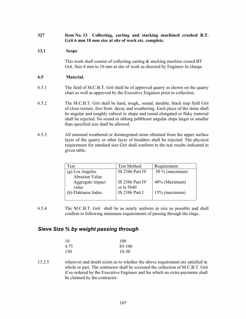
107
327 Item No. 13 Collecting, carting and stacking machined crushed B.T.
Grit 6 mm 10 mm size at site of work etc. complete. 13.1 Scope
This work shall consist of collecting carting & stacking machine crused BT Grit. Size 6 mm to 10 mm at site of work as directed by Engineer In charge.
6.5 Material. 6.5.1 The field of M.C.B.T. Grit shall be of approved quarry as shown on the quarry
chart as well as approved by the Executive Engineer prior to collection. 6.5.2 The M.C.B.T. Grit shall be hard, tough,, sound, durable, black trap field Grit
of close texture, free from decay and weathering. Each piece of the stone shall be angular and roughly cubical in shape and round elongated or flaky material shall be rejected. No round or oblong pebblesor angular chips larger or smaller than specified size shall be allowed.
6.5.3 All unsound weathered or disintegrated stone obtained from the upper surface
layer of the quarry or other layer of boulders shall be rejected. The physical requirement for standard size Grit shall conform to the test results indicated in given table.
Test Test Method Requirement (g) Los Angeles
Abrasion Value Aggregate impact value
(h) Flakiness Index
IS 2386 Part IV IS 2386 Part IV or Is 5640 IS 2386 Part I
50 % (maximum) 40% (Maximum) 15% (maximum)
6.5.4 The M.C.B.T. Grit shall be as nearly uniform in size as possible and shall
confirm to following minimum requirements of passing through the rings..
Sieve Size % by weight passing through
10 100 4.75 85-100 150 10-30
13.2.5 wherever and doubt exists as to whether the above requirement are satisfied in whole or part. The contractor shall be screened the collection of M.C.B.T. Grit if so ordered by the Executive Engineer and for which no extra payments shall be claimed by the contractor.

108
13.2.6 Any collection which does not fully satisfy the above requirement is liable to be rejected altogether.
13.3 Measurement for payments.
The item shall be measured in cubic meter for the complete item of work as directed by Engineer Incharge. Stacking shall be done by filling standard size boxes of 2mt. x 1.5mt. x 0.5mt. size. No deduction shall be made for voids from the grade measurements.
13.4 Rate
The contract unit rate for collecting carting & stacking of (6-10 B.T. Grit including all material labour tools equipments for construction & other incidental cost necessary to complete the work.

109
328 Item No. 14 Collecting, carting and stacking bituminous 80-100 grade at
site of work including stacking etc. complete.
1. Bitumen shall be procured directly from refinery by the Contractor. The contractor shall make adequate arrangements for storing bulk asphalt at site. The contractor will produce in original the bill of Refinery, all the gate passes issued by the refinery and the number of transport tanker. The contractor will also produce the Test Certificate regarding the grade of asphalt issued by Refinery. The Department does not undertake to furnish “P”n form (regarding Sales Tax Concessions) for purchase of asphalt.
2. On receipt and storage of bitumen. The bitumen shall be got tested in GERI leboratory or other Laboratories approved by Department.
3. The contractor will establish on site of work site laboratory in area not less than 25 sq.m with pucca construction and equipped; with instruments to enable to carry out the following tests. 1. Penetration test as per I.S. 1203. 2. Softing point test as per I.S.1204. 3. Ductility test as I.S.1208. 4. Viscocity test as per I.S.1206. 5. Specification Gravity test as for I.S. 1202.
The above instruments should be certified as per I.S. standard, the same should be regularly calibrated and should be maintained in efficient condition.
4. The Registers for use, temperature and other quality requirements of bitumen will be maintained at Plant site. The registers will be printed, as per formats approved by Department and authorised for use by the Engineer incharge. The entries in the registers will be made by the departmental representative and signed by the contractor or his authorised representative.
5. Frequency of Tests :
As regards quality of binder, three tests of one sample per two tankers will be done on plant site. The tests will be carried out as per Table 900-4 of Section 900 of MORTH standard specifications. The frequency of use of specifications will be as under. No of Tanker No of Tests. Upto 10 One 10 to 20 Two 20 to 50 Three 50 to 100 Four For further every 50 tanker One
6. The contract unit rate of supplying bitumen shall include 1. Obtaining the bitumen from the Refinery 2. Transporting to site. 3. Storing, stacking and protecting 4. Keeping record of supply and use and
7. Measurement for Payment
The Payment shall be made on tonnage basis.

110
Item No. 15 Laying of built up spray grout base course in one layer with bitumen at rate of 15 kg per 10 sqm and tack coat at rate of 5 kg per 10 sqm with 0.50cum of stone aggregates per 10 sqm and using 0.13 cum. Of key aggregates per 10 sqm excluding cost of materials bitumen and including rolling and consolidationn et. Complete.
15.1 Scope
This work shall consists of a two layer composite construction of compacted crushed coarse agrregates with application of bituminous binder aftereach layer, and with key aggregates placed on top of the second layer, in accordance with the requirements of these specification, to serve as base course and in conformity with the lines, grades and cross- sections shown on the drawings or as directed by the Engineer. The thickness of the course shall be 75mm. Built up spray grout shall be used in single course in pavement structure.
15.2 Materials
15.2.1 BITUMEN :
Clause 504.2.1 shall apply, where permitted by the engineer,an appropriate grade of emulation complying with IS 8887 may be used.
15.2.2 Aggregates :
The coarse aggregate shall conform to Clause 504.2.2
The aggregate shall satisfy the physical requirements act out in Table 500-3. The coarse and key aggregates for built-up spray grout shall conform to the grading given in Table . GRADING REQUIREMENTS FOR COARSE AND KEY AGGREGATES FOR BUILT UP SPRAY GROUT.
Cumulative per cent by weight of total aggregate passing
Is Sieve Designation (mm)
Coarse Aggregate Key Aggregate 53.0 100 - 26.5 40-75 - 22.4 - 100 13.2 0-20 40-75 5.6 - 0-20 2.8 0-5 0-5
15.3 Construction Operation 15.3.1 Weather and seasonal limitation :
The provisions of Clause 501.5.1 shall apply.

111
15.3.2 Equipment :
The provisions of Clause 505.3.2 shall apply.
15.3.3 Preparation of Base :
The base on which the built-up spray grout course is to be laid shall be prepared, shaped and compacted to the specified lines, grades and cross-section inn accordance with Clause 501- 902 as appropriate. A prime coat shall be applied in accordance with Clause 502 with approved primer as directed by Engineer.
15.3.4 Tack coat : A tack coat shall be applied in accordance with the procedure described in Clause 503, as directed by Engineer.
15.3.5 Spreading and rolling coarse aggregates for the first layer :
Immediately after the application of prime or tack coat, the clean, dry and dust free coarse aggregates shall be spread uniformly and evently, by mechanical means, at the rate of 0.5 cu.m per 10 sq.m.area.
Immediately after spreading of the aggregates, the entire surface shall be rolled with an 8-10 tonnes smooth wheel steel roller. Rolling shall commence at the edges and progress towards the centre except in superelevated and unit-directional cambered portions where it shall proceed from the lower edge to the higher edge. Each pass of the roller shall uniformly overlap not less than one-third of the track made in the preceding pass. The surface of the layer shall be carefully checked, after rolling with a temple and straight edge and shall be within the tolerances specified, andany deficiencies corrected by reworking and recompacting the layer. Care shall be taken not to over-compact the layer.
15.3.6 Application of binder – First Spray :
The binder shall be heated to the temperature appropriate to the grade of bitumen approved by the Engineer and sprayed on the aggregate at the rate of 15kg / 10 sqm (measured in terms of residual bitumen content) at a uniform rate of spray by mechanical sprayers capable of spraying bitumen uniformly at the specified rates and temperatures. Excessive deposits of binder caused by stopping or starting of the sprayers or through leakage or for any other reason shall be removed and made good.

112
15.3.7 Spreading and rolling of coarse aggregate for the second layer :
Immediately after the first application of the binder, the second layer of coarse aggregates shall be spread and rolled in accordance with the procedure detailed in Clause 506.3.5
15.3.8 Application of binder-second spray: The second ;aggregate layer shall then the sprayed with binder at the rate of 15 kg/ 10 sq.m (measured in terms of residual bitumen content) in accordance with Clause 506.3.6.
15.3.9 Application of key aggregate : Immediately after the second application of binder, key aggregates shall be spread uniformly and evenly, preferably by mechanical means, at the rate of 0.13cu.m /10 sq.m so as to cover the surface completely. The key aggregate shall be clean, dry and free form dust and deleterious matter. If necessary, the surface shall be swept to ensure uniform application of the key aggregates. The entire surface shall then be rolled with an 8-10 tonnes smooth wheel steel roller in accordance with Clause 506.3.5. While rolling is in progress, additional key aggregates, where required, shall be spread by hand. Rolling shall continue until the entire course is thoroughly compacted and the key aggregates are firmly in position.
15.4 Surface finish and Quality Control : The surface finish of construction shall conform to the requirements of Clause 902.All materials shall comply with the requirements of the relevant provisions in Section 900 of the Specifications.
15.5 Final Surfacing : The built up spray grout shall be provided with final surfacing within a maximum of forty eight hours. If there is to be any delay, the course shall be covered by seal coat to the requirement of Clause 513 before it is open to traffic. Where the seal coatis required as a result of the selected method of performing this operation, then it shall be considered incidental to the work and shall not be paid for separately.
15.6 Arrangements for Traffic :
During the period of construction, arrangement for traffic shall be made in accordance with the provisions of Clause 112.
15.7 Measurements for Payment Build-kup spray grout shall be measured as finished work in square meters.
15.8 Rate The contract unit rate for Built-up spray grout shall be payment in fully for carrying out the required operations as specified. The rate shall include for, but not necessarily be limited to the components listed in Clause 501.8.8.2(i) to (xi).
113
329 Item No. 16 Providing and laying tack coat using bituminous binder @ rate 2.5 kg 10 sq.m of road surface using bitumen pressure sprayer etc. complete including cost of asphalt .
16.1 TACK COAT
16.1.1 Scope
This work shall consist of the application of a single coat of low viscosity liquid bituminous material to an existing bituminous road surface preparatory to the superimposition of a bituminous mix, when specified in the Contract or instructed by the Engineer.
16.1.2 Materials
16.1.2.1 Binder The binder used for tack coat shall be bitumen emulsion complying with IS 8887 of a type and grade as specified in the Contract or as directed by the Engineer. The use of cutback bitumen as per IS 217 shall be restricted only for sites at sub-zero temperatures or for emergency applications as directed by the Engineer.
16.1.3 Weather and Seasonal Limitations Bituminous material shall not be applied to a wet surface or during a dust storm or when the weather is foggy, rainy or windy or when the temperature in the shade is less than 100C. Where the tack coat consists of emulsion, the surface shall be slightly damp, but not wet. Where the tack coat is of cutback bitumen, the surface shall be dry.
16.1.4 Construction
16.1.4.1 Equipment The tack coat distributor shall be a self – propelled or towed bitumen pressure sprayer, equipped for spraying the material uniformly at a specified rate. Hand spraying of small areas, inaccessible to the distributor, or in narrow strips, shall be sprayed with a pressure hand sprayer, or as directed by the Engineer.
16.1.4.2 Preparation of base The surface on which the tack coat is to be applied shall be clean and free from dust, dirt, and any extraneous material) and be otherwise prepared in accordance with the requirements of MORTH Clauses 501.8 and E16 Specifications for Quality Control as appropriate. (Immediately before the application of the tack coat, the surface shall be swept clean with mechanical broom, and high pressure air jet, or by other means as direction by the Engineer.)

114
16.1.4.3 Application of tack coat The application of tack coat shall be at the rate specified in the Contract, and shall be applied uniformly) If rate of application of Tack Coat is not specified in the contract then it shall be at the rate specified in MORTH Table 500-2. (The normal range of spraying
Type of Surface Quantity of liquid bituminous material in Kg per sq.m. area.
i) Normal bituminous surfaces ii) Dry and hungry bituminous surfaces iii) Granular surfaces treated with primer iv) Non bituminous surfaces a) Granular base (not primed) b) Cement concrete pavement
0.20 to 0.25 0.25 to 0.30 0.25 to .30
0.35 to 0.40 0.30 to 0.35
Temperature for a bituminous emulsion shall be 200C to 700C and for a cutback, 500C to 800C if RC-70/MC-70 is used). Where a geosynthetic is proposed for use, the provisions of MORTH Clauses 703.2 and 703.4.4 shall apply. (The method of application of the tack coat will depend on the type of equipment to be used, size of nozzles, pressure at the spray bar, and speed of forward movement. The Contractor shall demonstrate at a spraying trial, that the equipment and method to be used is capable of producing a uniform spray, within the tolerances specified. Where the material to receive an overlay is a freshly laid bituminous layer, that has not been subjected to traffic, or contaminated by dust, a tack coat is not mandatory where the overlay is completed within two days.
16.1.4.4 Curing of tack coat The tack coat shall be left to cure until all the volatiles have evaporated before any subsequent construction is started. (No plant or vehicles shall be allowed on the tack coat other than those essential for the construction) 16.1.5 Quality Control of Work For control of the quality of materials supplied and the works carried out, the relevant provisions of Section E Specifications for Quality Control shall apply. 16.1.6 Arrangements for Traffic During the period of construction, arrangements for traffic shall be made in accordance with the provisions of MORTH Clause 112. 16.1.7 Measurement for Payment Tack coat shall be measured in terms of surface area of application in square meters
16.1.8 Rate The rate quoted by the contractor for providing and laying tack coat as using bituminous binder at rate of 2.5 kg /10 sq.mt.

115
330 Item No.17 Providing and laying bituminous macadam 50 mm compacted thickness using specified graded crushed Black trap stone aggregate as per MORTH gradation specifications using 80/100 bulk bitumen for mixing at the rate of 3.5% (35 Kg./MT) by hot mix process and hot laid process, using sencer paver finisher to the required camber and grade and rolling with vibratory roller to achive desired density including cost of clearing using mechanical cleaner & collecting dust vaccume cleaner of required capacity disposing of the stuff withing 3 km lead as directed and using fier wood, oil, kerosene, labour charges and hire charges of the required machinery etc. complete. 17.2 BITUMINOUS MACADAM.
17.2.1 Scope This work shall consist of construction in a single course having 50mm to 100mm thickness or in multiple courses of compacted crushed aggregates premixed with a bituminous binder on a previously prepared base to the requirements of these Specifications. Bituminous macadam is more open graded than the dense graded bituminous materials described in MORTH Clauses 507, 508 and 509.
17.2.2 Materials
17.2.2.1 Bitumen The bitumen shall be paving bitumen of Penetration Grade complying with Indian Standard Specifications for “Paving Bitumen” IS : 73, and of the penetration indicated in MORTH Table 500 – 4.
17.2.2.2 Coarse aggregates The coarse aggregates shall consist of crushed rock, crushed gravel or other hard material retained on the 2.36 mm sieve. They shall be clean, hard, durable, of cubical shape, free from dust and soft or friable matter, organic or other deleterious matter. Where the Contractor's selected source of aggregates have poor affinity for bitumen, as a condition for the approval of that source, the bitumen shall be treated with approved anti-stripping agents, as per the manufacturer’s recommendations, without additional payment. Before approval of the source, the aggregates shall be tested for stripping. The aggregates shall satisfy the physical requirements set forth in MORTH Table 500-3. Where crushed gravel is proposed for use as aggregate, not less than 90% by weight of the crushed material retained on the 4.75 mm sieve shall have at least two fractured faces.
17.2.2.3 Fine aggregates Fine aggregates shall consist of crushed or naturally occuring material, or a combination of the two, passing 2.36 mm sieve and retained on 75 micron

116
sieve. They shall be clean, hard, durable, dry and free from dust, and soft or friable matter, organic or other deleterious matter.
MORTH TABLE 500-3. PHYSICAL REQUIREMENTS FOR COARSE AGGREGATES
FOR BITUMINOUS MACADAM
Property Test Specification Cleanliness Particle shape Strength Durability Water Absorption Stripping Water Sensitivity’
Grain size analysis’ Flakiness and Elongation Index (Combined) Los Angles Abrasion Value’ Aggregate Impact Value’ Soundness Sodium Sulphate Magnesium Sulphate Water absorption Coating and Stripping of Bitumen Aggregate Mixtures Retained Tensile Strength
Max 5% passing 0.075 mm sieve Max 30 % Max 40% Max 12 % Max 18 % Max 2 % Minimum retained coating 95% Min 80 %
Notes :1. IS ; 2386 Part 1 4. IS ; 2386 Part 5 2. IS ; 2386 Part 1 5. IS ; 2386 Part 3 (the elongation test to be done only on non-flaky aggregates in the sample) 3. IS ; 2386 Part 4* 6. IS ; 6241
7. The water sensitivity test is only to be carried out if the minimum retained Coating in the stripping test is less than 95%.
• Aggregate may satisfy requirements of either of these two tests.
17.2.2.4 Aggregate grading and binder content When tested in accordance with IS : 2386 Part 1 (wet sieving method), the combined aggregate grading for the particular mixture shall fall within the limits shown in MORTH Table 500-4 for the grading specified in the Contract. The type and quantity of bitumen, and appropriate thickness, are also indicated for each mixture type.
17.2.2.5 Proportioning of Material The aggregates shall be proportioned and blended to produce a uniform mixture complying with the requirements of MORTH Table 500-4. The binder content shall be within a tolerance of 0.3 per cent by weight of total mixture when individual specimens are taken for quality control tests in accordance with the provisions of Section E.
17.2.3 Construction Operations.
17.2.3.1 Weather and seasonal limitations :

117
The provisions of MORTH Clause 501.5.1 shall apply.
MORTH TABLE 500-4
COMPOSITION OF BITUMINOUS MACADAM
19 mm
50 – 75 mm
Mix designation Nominal aggregate size Layer thickness
IS Sieve (mm) Cumulative % by weight of total aggregate passing
45 37.5 26.5 100 19 90-100
13.2 56-88 4.75 16-36 2.36 4-19 0.3 2-10
0.075 0-8 Bitumen content, % by weight of total mixture
3.3 – 3.5
Bitumen grade 35 to 90
Notes ; 1. Appropriate bitumen contents for conditions in cooler areas of India may be up to 0.5 % higher subject to the approval of the Engineer.
17.2.3.2 Preparation of the base The base on which bituminous macadam is to be laid shall be prepared, shaped and compacted to the required profile in accordance with MORTH Clause 501.8 and E.16.3 as appropriate, and a prime coat, shall be applied in accordance with MORTH Clause 502 where specified, or as directed by the Engineer. 17.2.3.3 Tack Coat A tack coat in accordance with MORTH Clause 503 shall be applied as required by the Contract documents, or as directed by the Engineer.
17.2.3.4 Preparation and transportation of the mixture The provisions of MORTH Clauses 501.3 and 501.4 shall apply.
17.2.3.5 Spreading
The provisions of MORTH Clauses 501.5.3 shall apply. MORTH TABLE 500-5. MANUFACTURING AND ROLLING
TEMPERATURES

118
Bitumen Penetration
Bitumen Mixing(0C)
Aggregate Mixing(0C)
Mixed Material(0C)
Rolling (0C)
Laying (0C)
35 160-170 160 – 175 170 Maximum 100 Min. 130 Min. 65 150 – 165 150 – 170 165 Maximum 90 Min. 125 Min. 90 140 – 160 140 – 165 155 Maximum 80 Min. 115 Min.
17.2.3.6 Rolling
Compaction shall be carried out in accordance with the provisions of MORTH Clauses 501.6 and 501.7. The rolling shall be carried out with the help of vibratory roller of 8 to 10 tones capacity. Rolling shall be continued until the specified density is achieved, or where no density is specified, until there is no further movement under the roller. The required frequency of testing is defined in Clause E.17 Specifications for Quality Control.
17.2.4 Surface Finish and Quality Control of Work The surface finish of the completed construction shall conform to the requirements of Clause E.16. For control of the quality of materials supplied and the works carried out, the relevant provisions of Section E shall apply. 17.2.5 Protection of the Layer The bituminous macadam shall be covered with either the next pavement course of wearing course, as the case may be, within a maximum of forty-eight hours. If there is to be any delay, the course shall be covered by a seal coat to the requirement of MORTH Clause 513 before opening to any traffic. The seal coat in such cases shall be considered incidental to the work and shall not be paid for separately. 17.2.6 Arrangements for Traffic During the period of construction, arrangements for traffic shall be made in accordance with the provisions of MORTH Clause 112 of as directed by Engineer – in - Chrage.
17.2.7 Measurement for Payment Bituminous macadam shall be measured as finished work in cubic meters, or by weight in metric tonnes, where used as regulating course, or square meters at the specified thickness as indicated in the Contract or shown on the drawings, or as otherwise directed by the Engineer.
17.2.8 Rate The contract unit rate for bituminous macadam shall be payment in full for carrying out the required operations as specified.

119
Item No. 18 Providing and laying 20 mm thick mix seal surfacing using specified graded crushed Black trap stone aggregates as per MORTH gradation using 80/100 bulk bitumen for mixing @ 4.5% (45 KG/MT), by hot mix process and hot laid process using sencer paver finisher to the required camber and grade. Including rolling with vibratory roller to achieve desire density including cost of clearing fusing mechanical cleaner & collecting dust vacume cleaner of required capacity, disposing of the stuff within 3 km lead as directed and using fier wood oil, kerosene, labour charges ;and hire charges of machinaries etc. complete.
18.0 CLOSE – GRADED PREMIX SURFACING / MIXED SEAL
SURFACING
18.1. Scope
18.1.1 This work shall consists of the preparation, laying and compaction of a close-graded premix surfacing material of 20 mm thickness composed of graded aggregates premixed with a bituminous binder on a previously prepared surface, in accordance with the requirements of these Specifications, to serve as a wearing course.
18.1.2 Close graded premix surfacing shall be of Type A or Type B as specified in the Contract documents.
18.2 Materials 18.2.1 Binder :
The provisions of MORTH Clause 511.1.2.1 shall apply.
18.2.2 Coarse aggregates : The provisions of MORTH Clause 511.1.2.2 shall apply.
18.2.3 Fine aggregates :
The fine aggregates shall consist of crushed rock quarry sands, natural gravel / sand or a mixture of both. These shall be clean, hard, durable, un-coated, mineral particles, dry and free from injurious, soft or flaky particles and organic or deleterious substances.
18.2.4 Aggregate gradation : The coarse and fine aggregates shall be so graded or combined as to conform to one or the other grading shown in MORTH Table 500-26, as specified in the contract.

120
MORTH TABLE 500-26. AGGREGATE GRADATION
Cumulative per cent by weight of total aggregate passing
IS Sieve Designation
(mm) Type B 13.2 mm 100 11.2 mm 88-100 5.6 mm 31-52 2.8 mm 5-25
0.090 mm 0-5 18.2.5 Proportioning of materials :
The total quantity of aggregates used for premix surface shall be as indicated in the item and bitumen used for premixing in terms of straight-run bitumen shall be 80 / 100 bulk asphalt at ther rate of 5.103 % (51.03 kg/Mt).
18.3 Construction Operations The provisions of MORTH Clause 511.1.3.1 through 511.1.3.5 shall apply. The rolling shall be carried out with the help of vibratory roller of 8 to 10 tonnes capacity.
18.4 Opening to Traffic
Traffic may be allowed after completion of the final rolling when the mix has cooled down to the surrounding temperature . Excessive traffic speeds should not be permitted.
18.5 Surface Finish and Quality Control of Work The surface finish of construction shall conform to the requirements of Clause E16. For control on the quality of materials supplied and the works carried out, the relevant provisions of Section E shall apply.
18.6 Arrangements for Traffic During the period of construction, arrangements for traffic shall be in accordance with the provisions of MORTH Clause 112.
18.7 Measurements for Payment Close-graded premix surfacing, shall be measured as finished work, in cubic meter or by weight in metric tonnes where used as regulating course of square metters at the specified thickness as indicated in the contract or shown on the drawing or as otherwise directed by the Engineer.
18.8 Rate The contract unit rate for close-graded premix surfacing, shall be payment in full for carrying out the required operations.

121
Item No. 19 Providing and laying Asphalt Painting using bituminous binder @ rate of 10 kg/ 10sq.m of road surface using bituminous pressure sprayer etc. complete as per Technical Specification.
19.1. Scope
This work shall consist of the application of a single coat of low viscosity liquid bituminous material to the superimposition of bituminous treatment or mix.
19.2 Materials 19.2.1 Primer:
The choice of a bituminous primer shall depends upon the porosity characteristics of the surface to be primed as classified in IRC:16 These are
(i) Surface of low porosity :such as wet mix macadam and water bound
macadam. (ii) Surfaces of medium porosity : such as cement stabilised soil base. (iii) Surface of high porosity : such as a gravel base. 19.2.2 Primer viscosity :
The type and viscosity of the primer shall comply with the requirements of IS 8887 , as sampled and tested for bituminous primer in accordance with these standards. Guidance on viscosity and rate of spray is give in Table.
Type of Surface Kinematic Viscosity of Primer
at 60o C (Centistokes)
Quantity of Liquid Bituminous
Material per 10 Sq.m. (kg)
Low Porosity 30-60 6 to 9 Medium porosity 70-140 9 to 12 High porosity 250-500 12 to 15
19.2.3 Choice of Primer :
The primer shall be bitumen emulsion, complying with IS 8887 of type and grade as specified in the contract or as directed by the Engineer. The use of medium curing cutback as per IS 217 shall be restricted only for sites at sub-zero temperatures or for emergency applications as directed by the Engineer.
19.3 Weather and Seasonal Limitations : Bituminous primer shall not be applied to a wet surface (see 502.4.2) or during a dust storm or when the weather is foggy, rainy or windy or when the temperature in the shade is less than 10o C. Surface which are to receive emulsion primer should be damp, but no free or standing water shall be present.
19.4 Construction

122
19.4.1 Equipment:
The primer distributor shall be self-propelled or toward bitumen pressure sprayer equipped for spraying the material uniformly at specified rates and temperatures. Hand spraying of small areas, inaccessible to the distributor, or in narrow strips shall be sprayed with a pressure hand sprayer, or as directed by the Engineer.
19.4.2 Preparation of road Surface :
The surface to he primed shall be prepared in accordance with Clauses 501.8 and 902 as appropriate. Immediately prior to applying the primer the surface shall be carefully swept clean of dust and loose particles, care being taken not to disturb the interlocked aggregate. This is best achieved when the surface layer is slightly moist (lightly sprayed with water and the surface allowed to dry) and the surface should be kept moist until the primer is applied.
19.4.3 Application of bituminous primer :
The viscosity and rate of application of the primer shall be as specified in the contract, or as determined by site trials carried out as directed by the Engineer. Where a geosynthetic is proposed for use, the requirements of Clause 703.3.2 and 703.4 shall apply. The bituminous primer shall be sprayed uniformly in accordance with Clause 501. The method for application of the primer will depend on the type of equipment to be used size of nozzles, pressure at the spray bar and speed of forward movement. The Contractor shall demonstrate at a spraying trial, that the equipment and method to be used is capable of producing a uniform spray, within the tolerances specified.
19.4.4 Curing of primer and opening to traffic :
A primer surface shall be allowed to cure for at least 24 hours or such other period as is found to be necessary to allow all the volatiles to evaporate before any subsequent surface treatment of mix is laid. Any unabsorbed primer shall first be blotted with an application of sand, using the minimum quantity possible. A primed surface shall not be opened to traffic other than that necessary to lay the next course. A very thin layer of clean sand may be applied to the surface of the primer, to prevent the primer picking up under the wheels of the paver and the trucks delivering bituminous material to the paver.
19.4.5 Tack Coat :
Over the primed surface, a tack coat should be applied in accordance with Clause 503.
19.5 Quality Control of Work

123
For control of the quality of materials supplied and the works carried out, the relevant provisions of Section 900 shall apply.
19.6 Arrangements for Traffic
During constructions operations, arrangements for traffic shall be made in accordance with the provisions of Clause 112.
19.7 Measurement of Payment
Prime coat shall be measured in terms of surface area of application in square meters.
19.8 Rate :
The contract unit rate for prime coat with adjustments as described in Clause 502.7 shall be payment in full for carrying out the required operations including full compensation for all components listed in Clause 401.8 (I) to (v) and as applicable to the work specified in these specifications. Payment shall be made on the basis of the provision of prime coat at an application rate of 1 kg per square meter, with adjustment, plus or minus, for the variation between this amount and the actual amount approved by the Engineer after the preliminary trials referred to in Clause 502.4.3.

124
Item No. 20 Providing, laying and jointing RCC NP3 hume pipes 300 mm dia under the road for crossing the future public utilities at every 200 mt. location as directed and as per Technical Specifications MORTH clause 2900.
The contractor will make necessary arrangement for future public utilities crossing the road by providing 300 mm dia RCC pipe at every 200 m interval under the road and the pipe will be issued as directed. The pipe shall be NP3 type pipe of 300 mm internal dia meter. Measurement will be taken in meter and the payment will be made on linear meter of the pipe provided, laid. The specification MORTH clause 2900 will be followed for this item.

125
Item No. 21 Providing and laying inter locking Paver Block flooring of 80 mm thick of
gray cement and grey color finished laid on 20mm (average) the. Base of coarse sand laid over and jointed with grey cement slurry incl. Finished etc. complete.
21.1. Scope
This work shall consist of constructing interlocking paver block flooring with the line levels and dimension as specified in the drawings.
Materials
The compressive strength of the interlocking paver block shall be minimum 400 kg/sq.cm and water absorption should be less than 6 % by weight. Abrasion resistance should be less than 2 (maximum permissible value 3 mm ) same shall be manufactured by automatic press and compaction must included vibration and pressing force not less than 200 tones. The blocks should be steam cured.
Construction Operation : Base on which the paver blocks to be laid shall be leveled and well compacted with mechanical compactor Special care of consolidation shall be taken to assure a permanent laying. The depth of the base shall be as per the design and drawing. Base shall be leveled properly. It shall be done with long and strong skreed board. Pipes or skreeding bar may also be used. A frame of steel section shall be made to maintain the base. The skreed shall not be warped or twisted.
The pavers shall be placed in the pattern as per framing and detail close together. The space between the paver should be minimum and consistent. The overall pattern shall be uniform. If require, then the stone shall be cut with a splitter chiesel or masonary saw as require. The pavers should then be tamped down and leveled with a vibrating plate compactor. This will bring the pavers to their true grade as well as level the stones. Sand will be forced into spaces to make stones firm and free of movement. Dry fine sand shall be sweeped above the paver block.
Measurement for payment.
Paver Block flooring shall be measured in terms of surface area of application
in square meters. Rate :
The contract unit rates for paver block flooring shall be payment in full compensation for furnishing all materials, labour, tools, equipment for construction and other incidental cost necessary to complete the work.

126
Item No. 22 Providing and laying kerbing for inter locking paver block flooring of 250 mm x 150 mm x 60 mm of gray cement and gray / color finished laid on 10 cm (average ) th. Base of c.c. 1 :5:10 and laid over and jointed with grey cement slurry incl. Finished etc. complete.
22.1. Scope
This work shall consist of providing and laying kerbing for interlocking paver block flooring (250 mm x 150mm x 60mm) with the line levels and dimension as specified in the drawings.
22.2 Materials
Kerbing shall be provided in cement concrete of grade M 40 in accordance with MORTH section 1700 of these specifications.
22.3 Types of construction.
The precast concrete blocks shall be used.
22.4 Equipment :
For precast kerb casting equipment of adequate capacity and controls, capable of laying the kerbs in required cross-sections and producing a well compacted mass of concrete free of voids and honeycombs by using plate / pocker vibrator.
22.5 Construction operations.
Kerb shall be laid on firm foundation of cc 1:5:10 laid on extended width of pavement. The foundation shall have a projection of 50 mm beyond the kerb stone. In the median portion in the straight reaches, the kerb shall be precast. In the portions where footpath is provided and/or the slope of the carriageway is towards median (as in case of superelevated portions), there shalll be sufficient gap / recess left in the kerb to factilitate drainage openings. After laying the precast kerbs, saw cut grooves shall be provided at 5m intervals or as specified by the Engineer. Kerbs on drainage ends such as long the footpath or the median in superelevated portions, shall be cast with monolithie concrete channels as indicated in drawings, the slope of the channel towards drainage pipes shall be ensured for efficient drainage of the road surface. Vertical and horizontal tolerances with respect to true line and level shall be ± 6mm.
127
22.6 Measurement for Payment :
Kerbing shall be measured in terms of surface area of application in running meters.
22.7 Rate :
The contract unit rates for kerbing shall be payment in full compensation for furnishing all materials, labour, tools, equipment for construction and other incidental cost necessary to complete the work.
Related Documents