28.04.2009 1 ETH Zürich Institute for Geodesy and Photogrammetry - Prof. Dr. H. Ingensand Road Design Road Design Werner Stempfhuber Werner Stempfhuber 30.4.2009 (Lecture and Exercise) 30.4.2009 (Lecture and Exercise) ETH Zürich Institute for Geodesy and Photogrammetry - Prof. Dr. H. Ingensand - Introduction - Reference Network - Transformation Parameter – Coordinate Systems - Design Parameter & Definition - Design Preparation (Leica System1200 OnBoard ATK, Liscad) - Calculation - Stake Out with the Leica RoadRunner - As Built Check - Exercise Content Content

Welcome message from author
This document is posted to help you gain knowledge. Please leave a comment to let me know what you think about it! Share it to your friends and learn new things together.
Transcript
28.04.2009
1
ETH ZürichInstitute for Geodesy and Photogrammetry - Prof. Dr. H. Ingensand
Road DesignRoad Design
Werner StempfhuberWerner Stempfhuber
30.4.2009 (Lecture and Exercise)30.4.2009 (Lecture and Exercise)
ETH ZürichInstitute for Geodesy and Photogrammetry - Prof. Dr. H. Ingensand
- Introduction
- Reference Network
- Transformation Parameter – Coordinate Systems
- Design Parameter & Definition
- Design Preparation (Leica System1200 OnBoard ATK, Liscad)
- Calculation
- Stake Out with the Leica RoadRunner
- As Built Check
- Exercise
ContentContent
28.04.2009
2
ETH ZürichInstitute for Geodesy and Photogrammetry - Prof. Dr. H. Ingensand
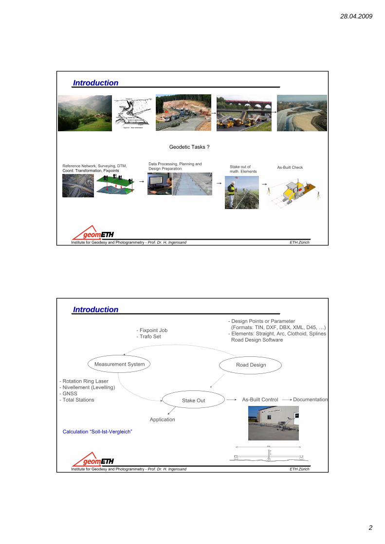
IntroductionIntroduction
Geodetic Tasks ?
Reference Network, Surveying, DTM, Coord. Transformation, Fixpoints
Data Processing, Planning and Design Preparation Stake out of
math. ElementsAs-Built Check
ETH ZürichInstitute for Geodesy and Photogrammetry - Prof. Dr. H. Ingensand
IntroductionIntroduction
Measurement System Road Design
Stake Out
- Design Points or Parameter(Formats: TIN, DXF, DBX, XML, D45, …)
- Elements: Straight, Arc, Clothoid, SplinesRoad Design Software
Calculation “Soll-Ist-Vergleich”
- Rotation Ring Laser- Nivellement (Levelling)- GNSS- Total Stations As-Built Control
Application
Documentation
- Fixpoint Job - Trafo Set
28.04.2009
3
ETH ZürichInstitute for Geodesy and Photogrammetry - Prof. Dr. H. Ingensand
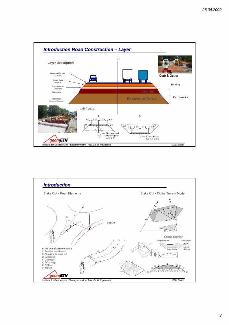
IntroductionIntroduction Road Construction Road Construction –– LayerLayer
Formation(Original Ground)
Subgrade
CL
Base Course(Asphalt)
Road Base(Asphalt)
Wearing Course(Asphalt)
Earthworks
Paving
Layer Description
Excavator/Dozer
Grader
Curb & Gutter
anti-freeze
ETH ZürichInstitute for Geodesy and Photogrammetry - Prof. Dr. H. Ingensand
IntroductionIntroductionStake Out - Road Elements Stake Out - Digital Terrain Model
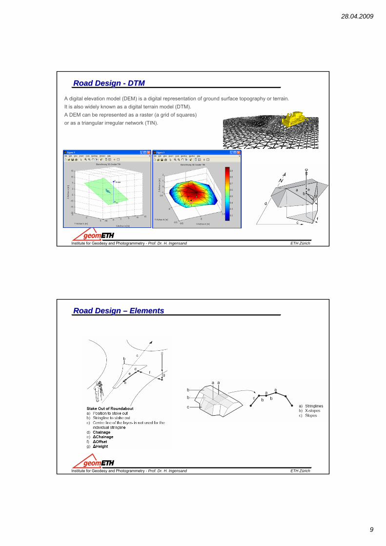
Stake Out of a Roundabouta) Position to stake outb) Stringline to stake outc) Centrelined) Chainagee) ΔChainagef) ΔOffsetg) ΔHeigh
LL CL RL
Offset
Cross Section
28.04.2009
4
ETH ZürichInstitute for Geodesy and Photogrammetry - Prof. Dr. H. Ingensand
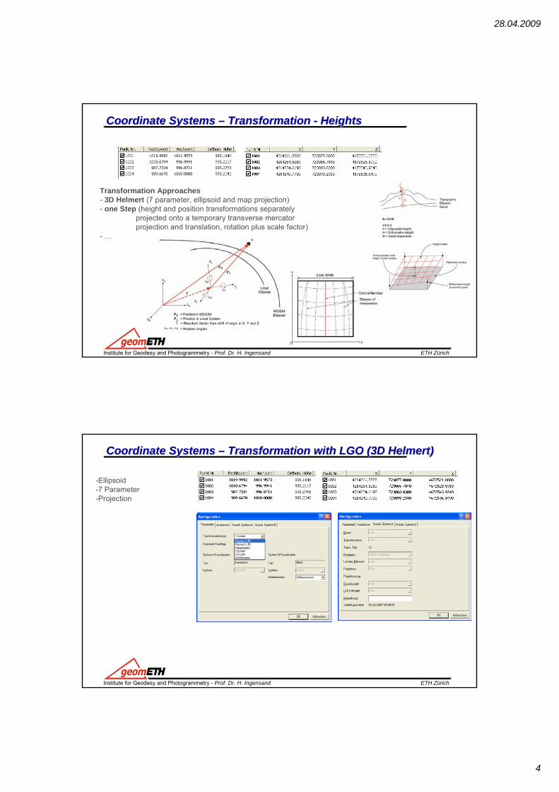
Coordinate Systems Coordinate Systems –– Transformation Transformation -- HeightsHeights
Transformation Approaches- 3D Helmert (7 parameter, ellipsoid and map projection) - one Step (height and position transformations separately
projected onto a temporary transverse mercatorprojection and translation, rotation plus scale factor)
- …
ETH ZürichInstitute for Geodesy and Photogrammetry - Prof. Dr. H. Ingensand
-Ellipsoid-7 Parameter-Projection
Coordinate Systems Coordinate Systems –– Transformation with LGO (3D Transformation with LGO (3D HelmertHelmert))
28.04.2009
5
ETH ZürichInstitute for Geodesy and Photogrammetry - Prof. Dr. H. Ingensand
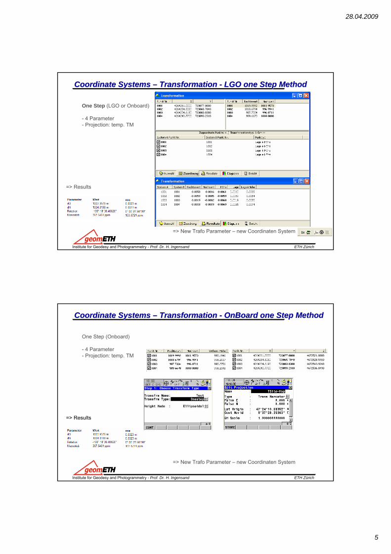
One Step (LGO or Onboard)
- 4 Parameter- Projection: temp. TM
=> New Trafo Parameter – new Coordinaten System
=> Results
Coordinate Systems Coordinate Systems –– Transformation Transformation -- LGO one Step MethodLGO one Step Method
ETH ZürichInstitute for Geodesy and Photogrammetry - Prof. Dr. H. Ingensand
One Step (Onboard)
- 4 Parameter- Projection: temp. TM
=> New Trafo Parameter – new Coordinaten System
=> Results
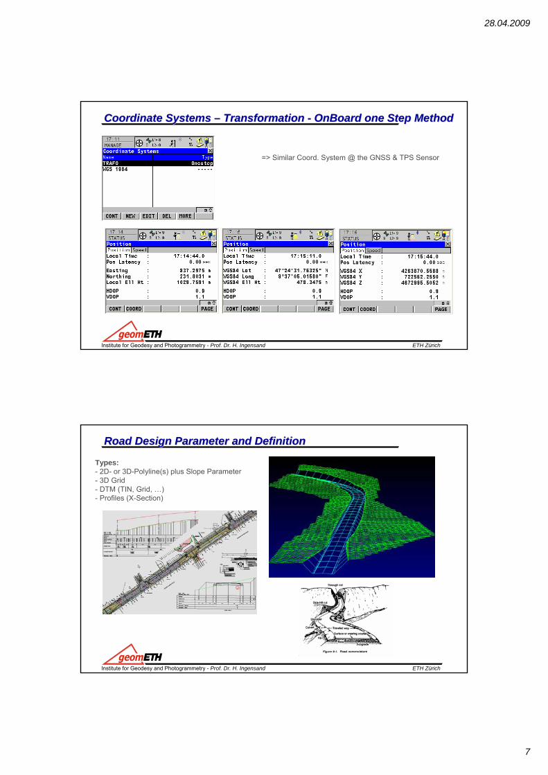
Coordinate Systems Coordinate Systems –– Transformation Transformation -- OnBoardOnBoard one Step Methodone Step Method

28.04.2009
6
ETH ZürichInstitute for Geodesy and Photogrammetry - Prof. Dr. H. Ingensand
One Step (Onboard)
- 4 Parameter- Projection: temp. TM
Coordinate Systems Coordinate Systems –– Transformation Transformation -- OnBoardOnBoard one Step Methodone Step Method
Exercise:
Binary Code (Type is not displayed)
ETH ZürichInstitute for Geodesy and Photogrammetry - Prof. Dr. H. Ingensand
Start GNSS Simulator- Check TPS and GNSS Fixpoint Jobs- Start Onboard Application- Select Jobs- Define Method- Match Points
- Calc
Coordinate Systems Coordinate Systems –– Transformation Transformation -- OnBoardOnBoard one Step Methodone Step Method
Exercise:
28.04.2009
7
ETH ZürichInstitute for Geodesy and Photogrammetry - Prof. Dr. H. Ingensand
=> Similar Coord. System @ the GNSS & TPS Sensor
Coordinate Systems Coordinate Systems –– Transformation Transformation -- OnBoardOnBoard one Step Methodone Step Method
ETH ZürichInstitute for Geodesy and Photogrammetry - Prof. Dr. H. Ingensand
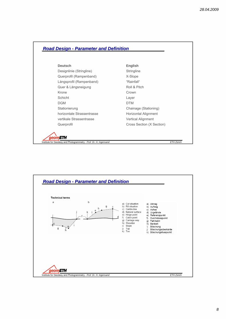
Road Design Parameter and DefinitionRoad Design Parameter and Definition
Types: - 2D- or 3D-Polyline(s) plus Slope Parameter- 3D Grid- DTM (TIN, Grid, …)- Profiles (X-Section)
28.04.2009
8
ETH ZürichInstitute for Geodesy and Photogrammetry - Prof. Dr. H. Ingensand
Road Design Road Design -- Parameter and DefinitionParameter and Definition
Deutsch EnglishDesignlinie (Stringline) StringlineQuerprofil (Rampenband) X-SlopeLängsprofil (Rampenband) “Rainfall“Quer & Längsneigung Roll & PitchKrone CrownSchicht Layer DGM DTMStationierung Chainage (Stationing)horizontale Strassentrasse Horizontal Alignmentvertikale Strassentrasse Vertical AlignmentQuerprofil Cross Section (X Section)
ETH ZürichInstitute for Geodesy and Photogrammetry - Prof. Dr. H. Ingensand
Road Design Road Design -- Parameter and DefinitionParameter and Definition
28.04.2009
9
ETH ZürichInstitute for Geodesy and Photogrammetry - Prof. Dr. H. Ingensand
Road Design Road Design -- DTMDTM
A digital elevation model (DEM) is a digital representation of ground surface topography or terrain. It is also widely known as a digital terrain model (DTM). A DEM can be represented as a raster (a grid of squares) or as a triangular irregular network (TIN).
ETH ZürichInstitute for Geodesy and Photogrammetry - Prof. Dr. H. Ingensand
Road Design Road Design –– ElementsElements

28.04.2009
10
ETH ZürichInstitute for Geodesy and Photogrammetry - Prof. Dr. H. Ingensand
Road DesignRoad DesignThe Horizontal Alignment
The horizontal alignment defines the road axis of a project. The constituting elements of ahorizontal alignment are:
• straights (tangents)• curves (arcs)• spirals (clothoid or cubic parabola).
Each constituting element is defined by individual horizontal design elements such aschainage, easting, northing, radius and parameter (A2 = R * L).
In Easting and Northing
ETH ZürichInstitute for Geodesy and Photogrammetry - Prof. Dr. H. Ingensand
Road DesignRoad Design
Elements:The Tangent - straight line between two points. It's end pointis identical with the beginning of a curve or spiral. The tangentis perpendicular to the radius of the curve.
The Curve (Arc) - circular curve with constant radius.
Spiral in - spiral transition from tangent to curve. Spiral out - spiral transition from curve to tangent.

28.04.2009
11
ETH ZürichInstitute for Geodesy and Photogrammetry - Prof. Dr. H. Ingensand
Road DesignRoad DesignThe Vertical AlignmentThe vertical alignment gives information about the pattern of heights of the road axis as itis defined in the horizontal alignment.The constituting elements of a vertical alignment are:
• tangents (straight segments)• curves• parabolas.
Each constituting element is defined by individual vertical design elements such aseasting, northing, radius and chainage.
Height
Chainage
0+00
0.00
ETH ZürichInstitute for Geodesy and Photogrammetry - Prof. Dr. H. Ingensand
Road DesignRoad Design
Cross SectionA cross section gives a profile view. It requires vertical alignment or actual elevation on each station.The constituting elements are straight elements. The points are called vertices. You may optionally define slopes at the vertices most left and most right.
Points are defined by:• ∆H and ∆V• ∆H and slope in percentage• ∆H and slope ratio∆H horizontal distance from the centre line∆V vertical distance from the centre line (vertical alignment or actual elevation mandatory) − ∆V
28.04.2009
12
ETH ZürichInstitute for Geodesy and Photogrammetry - Prof. Dr. H. Ingensand
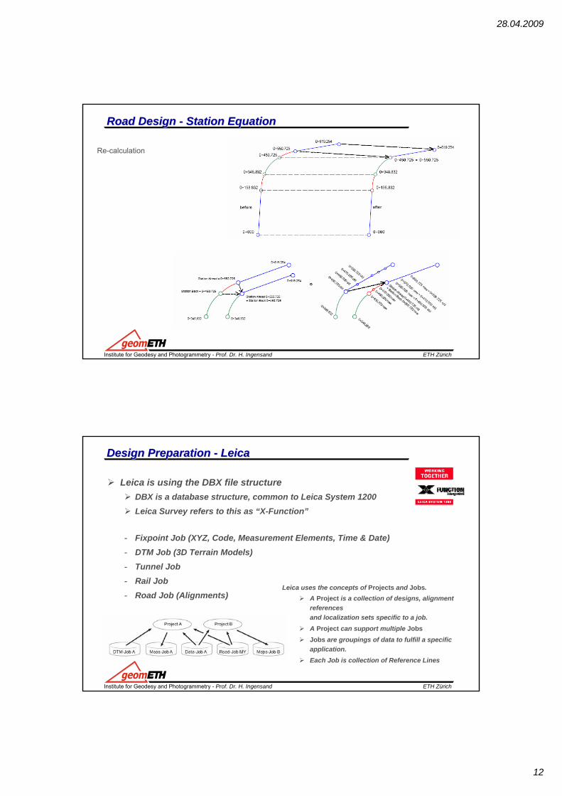
Road DesignRoad Design -- Station EquationStation Equation
Re-calculation
ETH ZürichInstitute for Geodesy and Photogrammetry - Prof. Dr. H. Ingensand
Design Design Preparation Preparation -- LeicaLeica
Leica is using the DBX file structureDBX is a database structure, common to Leica System 1200Leica Survey refers to this as “X-Function”
- Fixpoint Job (XYZ, Code, Measurement Elements, Time & Date)- DTM Job (3D Terrain Models)- Tunnel Job - Rail Job - Road Job (Alignments)
Leica uses the concepts of Projects and Jobs.A Project is a collection of designs, alignment references and localization sets specific to a job. A Project can support multiple JobsJobs are groupings of data to fulfill a specific application.Each Job is collection of Reference Lines
28.04.2009
13
ETH ZürichInstitute for Geodesy and Photogrammetry - Prof. Dr. H. Ingensand
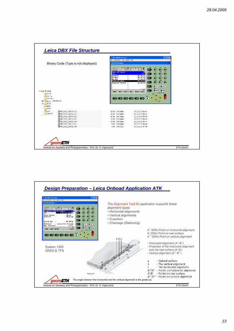
Leica DBX File StructureLeica DBX File Structure
Binary Code (Type is not displayed)
XML\RR.xml
ETH ZürichInstitute for Geodesy and Photogrammetry - Prof. Dr. H. Ingensand
Design Design Preparation Preparation –– Leica Leica OnboadOnboad Application ATKApplication ATK
The Alignment Tool Kit application supports these alignment types:• Horizontal alignments• Vertical alignments• X-section• Chainage (Stationing)
System 1200 GNSS & TPS
A’’ (ENh) Point on horizontal alignmentA’ (ENh) Point on real surfaceA’’’ (ENh) Point on vertical alignment
- Horizontal alignment (A’’-B’’)- Projection of the horizontal alignmentonto the real surface (A’-B’)
- Vertical alignment (A’’’-B’’’)
The angle between the horizontal and the vertical alignment is the grade (α).
28.04.2009
14
ETH ZürichInstitute for Geodesy and Photogrammetry - Prof. Dr. H. Ingensand
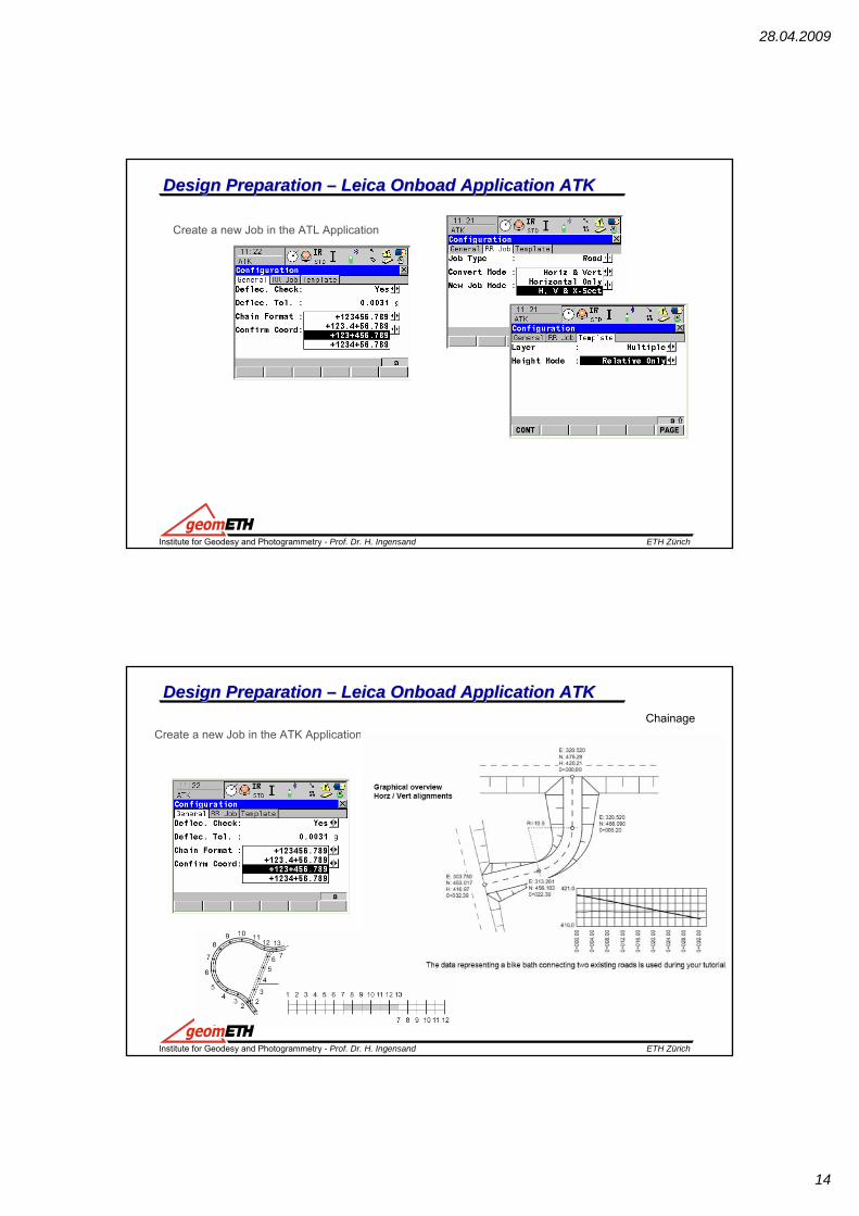
Design Design Preparation Preparation –– Leica Leica OnboadOnboad Application ATKApplication ATK
Create a new Job in the ATL Application
ETH ZürichInstitute for Geodesy and Photogrammetry - Prof. Dr. H. Ingensand
Design Design Preparation Preparation –– Leica Leica OnboadOnboad Application ATKApplication ATK
Create a new Job in the ATK ApplicationChainage

28.04.2009
15
ETH ZürichInstitute for Geodesy and Photogrammetry - Prof. Dr. H. Ingensand
Design Design Preparation Preparation –– Leica Leica OnboadOnboad Application ATKApplication ATK
Create and Edit a Alignment
Create in CF Card\Data\XML\ Example ATK.xml
ETH ZürichInstitute for Geodesy and Photogrammetry - Prof. Dr. H. Ingensand
Design Design Preparation Preparation –– Leica Leica OnboadOnboad Application ATKApplication ATK
Horizontal Alignment
From Fixpoint Job or measure
Add point

28.04.2009
16
ETH ZürichInstitute for Geodesy and Photogrammetry - Prof. Dr. H. Ingensand
Design Design Preparation Preparation –– Leica Leica OnboadOnboad Application ATKApplication ATK
delete point => Chainage
Horizontal Alignment
ETH ZürichInstitute for Geodesy and Photogrammetry - Prof. Dr. H. Ingensand
Design Design Preparation Preparation –– Leica Leica OnboadOnboad Application ATKApplication ATK
Vertical Alignment
Parameter-Straight-Parabola (Grade In/Out, 2:1 hv)-Curve (Sag or Crest)
28.04.2009
17
ETH ZürichInstitute for Geodesy and Photogrammetry - Prof. Dr. H. Ingensand
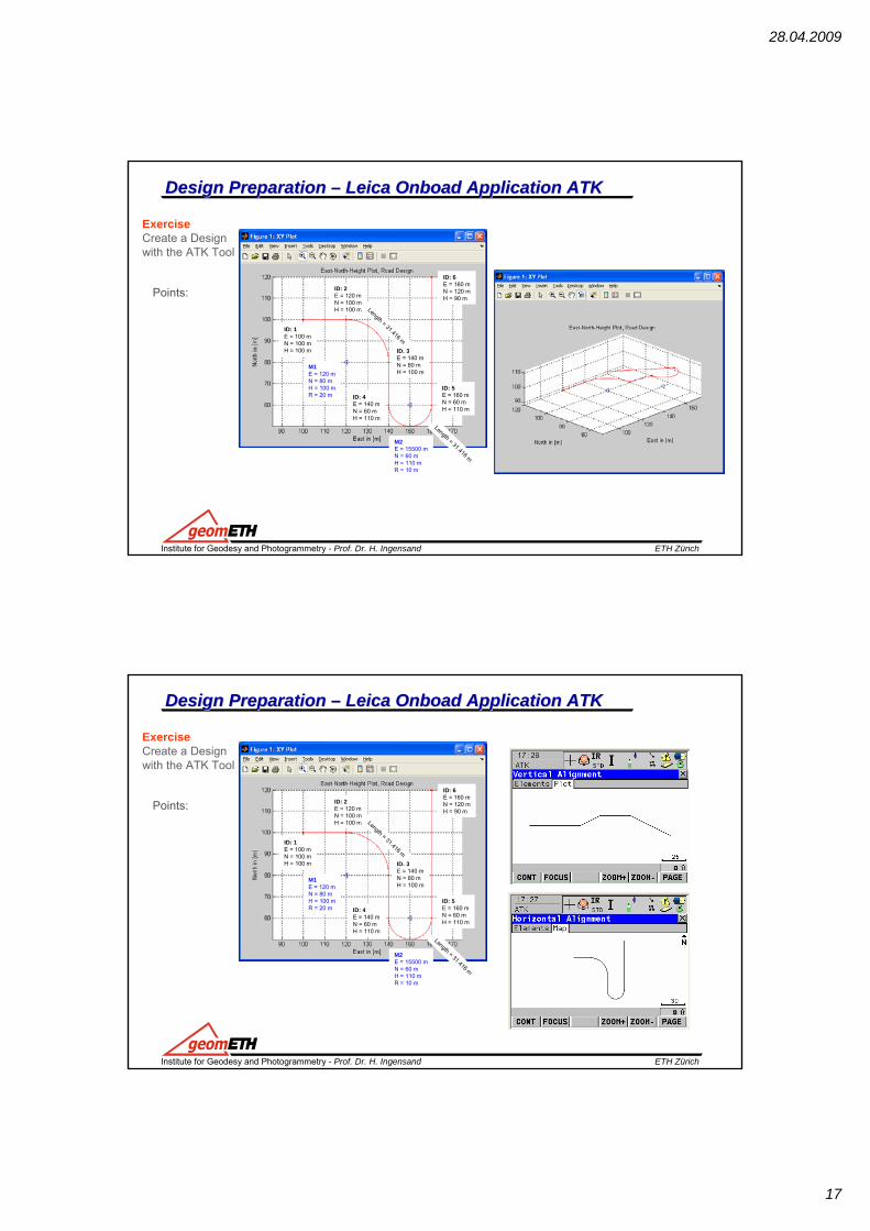
Design Design Preparation Preparation –– Leica Leica OnboadOnboad Application ATKApplication ATK
Exercise Create a Designwith the ATK Tool
Points:
ID: 1E = 100 mN = 100 mH = 100 m
ID: 2E = 120 mN = 100 mH = 100 m
ID: 3E = 140 mN = 80 mH = 100 m
ID: 4E = 140 mN = 60 mH = 110 m
M1E = 120 mN = 80 mH = 100 mR = 20 m
M2E = 15500 mN = 60 mH = 110 mR = 10 m
ID: 5E = 160 mN = 60 mH = 110 m
ID: 6E = 160 mN = 120 mH = 90 m
Length = 31.416 m
Length = 31.416 m
ETH ZürichInstitute for Geodesy and Photogrammetry - Prof. Dr. H. Ingensand
Design Design Preparation Preparation –– Leica Leica OnboadOnboad Application ATKApplication ATK
Exercise Create a Designwith the ATK Tool
Points:
ID: 1E = 100 mN = 100 mH = 100 m
ID: 2E = 120 mN = 100 mH = 100 m
ID: 3E = 140 mN = 80 mH = 100 m
ID: 4E = 140 mN = 60 mH = 110 m
M1E = 120 mN = 80 mH = 100 mR = 20 m
M2E = 15500 mN = 60 mH = 110 mR = 10 m
ID: 5E = 160 mN = 60 mH = 110 m
ID: 6E = 160 mN = 120 mH = 90 m
Length = 31.416 m
Length = 31.416 m
28.04.2009
18
ETH ZürichInstitute for Geodesy and Photogrammetry - Prof. Dr. H. Ingensand
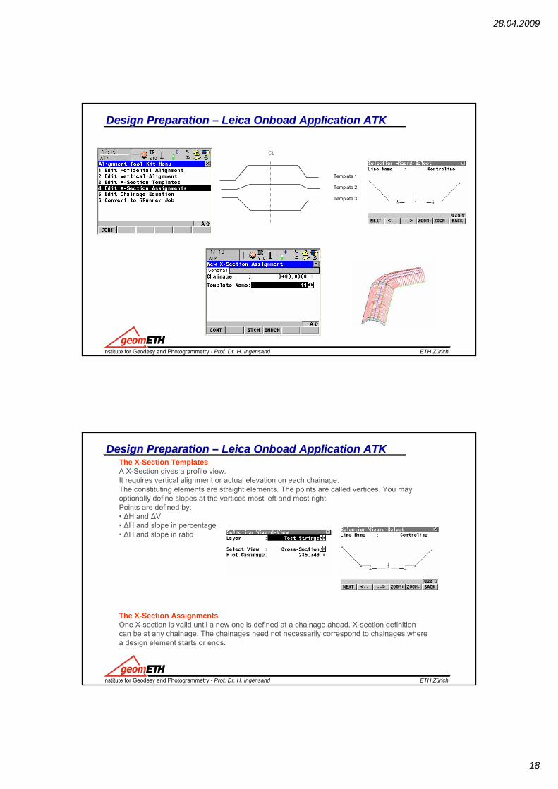
Design Design Preparation Preparation –– Leica Leica OnboadOnboad Application ATKApplication ATK
Template 1
Template 2
Template 3
CL
ETH ZürichInstitute for Geodesy and Photogrammetry - Prof. Dr. H. Ingensand
Design Design Preparation Preparation –– Leica Leica OnboadOnboad Application ATKApplication ATKThe X-Section TemplatesA X-Section gives a profile view. It requires vertical alignment or actual elevation on each chainage.The constituting elements are straight elements. The points are called vertices. You mayoptionally define slopes at the vertices most left and most right.Points are defined by:• ΔH and ΔV• ΔH and slope in percentage• ΔH and slope in ratio
The X-Section AssignmentsOne X-section is valid until a new one is defined at a chainage ahead. X-section definitioncan be at any chainage. The chainages need not necessarily correspond to chainages wherea design element starts or ends.

28.04.2009
19
ETH ZürichInstitute for Geodesy and Photogrammetry - Prof. Dr. H. Ingensand
Design Design Preparation Preparation –– Leica Leica OnboadOnboad Application ATKApplication ATK
The Chainage equationChainage Equations define adjustments for the chainage values in the horizontal alignment.These adjustments may be necessary when the horizontal alignments has been modified byinserting or removing a constituting element and the chainage in the horizontal alignmentwere not recomputed. This can be the case when editing manually or with a program whichdoes no automatic recomputation.
Convert to RoadRunner JobATK creates a log file during the conversion.
The file LandXml2Dbx.log can befound in the \Data\XML folder on the CF Card
ETH ZürichInstitute for Geodesy and Photogrammetry - Prof. Dr. H. Ingensand
Design Design Preparation Preparation –– Leica Leica OnboadOnboad Application ATKApplication ATK

28.04.2009
20
ETH ZürichInstitute for Geodesy and Photogrammetry - Prof. Dr. H. Ingensand
Additional Slides
ETH ZürichInstitute for Geodesy and Photogrammetry - Prof. Dr. H. Ingensand
Stake out Stake out withwith Leica Leica RoadRunnerRoadRunner
The data representing a bike bath connecting two existing roads.This Design is used during the RR Exercise.
The bike path changes from a fill to a cut. Two different types of cross sections are used.
3 Layers

28.04.2009
21
ETH ZürichInstitute for Geodesy and Photogrammetry - Prof. Dr. H. Ingensand
Stake out Stake out withwith Leica Leica RoadRunnerRoadRunner -- Setup Setup Setup TPS
E
N
E = 305 mN = 475 mH = 418 m
E = 306.026 mN = 446.027 m
E = 327.870 mN = 475.290 m
E = 301.489 mN = 460.000 m
Copy RR Files (RR_0330_143616.*) in … IntMem\DBX
ETH ZürichInstitute for Geodesy and Photogrammetry - Prof. Dr. H. Ingensand
Stake out Stake out withwith Leica Leica RoadRunnerRoadRunner -- ConfigConfigCreating the Project and RR Task, RR Configuration

28.04.2009
22
ETH ZürichInstitute for Geodesy and Photogrammetry - Prof. Dr. H. Ingensand
Stake out Stake out withwith Leica Leica RoadRunnerRoadRunner -- ConfigConfigCont => New Define a new Task
Project configurations, they are common for the whole project. For example how chainages are displayed.
Road configurations, they are road specific.For example the working corridor left andright of the alignment.
All configurations can be stored in configuration sets.
Press SHIFT CONF (F2) to access Configuration
ETH ZürichInstitute for Geodesy and Photogrammetry - Prof. Dr. H. Ingensand
Stake out Stake out withwith Leica Leica RoadRunnerRoadRunner -- ConfigConfigChange Configuration / eg. Road Config Shift/Conf/Road Config/Info&Plt Change
Compare RR Manual (GNSS or TPS)

28.04.2009
23
ETH ZürichInstitute for Geodesy and Photogrammetry - Prof. Dr. H. Ingensand
Stake out Stake out withwith Leica Leica RoadRunnerRoadRunner –– Stake outStake outStake out – CenterLine (Hubs or Peg every 5m) Straight Line
Load Exercise_2 (DBX)After RR Start select Resum
ETH ZürichInstitute for Geodesy and Photogrammetry - Prof. Dr. H. Ingensand
Stake out Stake out withwith Leica Leica RoadRunnerRoadRunner –– Stake outStake out
Next Chainage +5m
28.04.2009
24
ETH ZürichInstitute for Geodesy and Photogrammetry - Prof. Dr. H. Ingensand
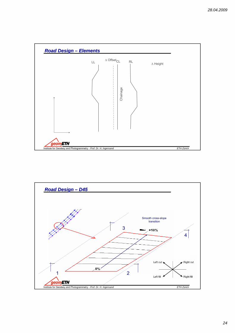
Road Design Road Design –– ElementsElements
CLΔ OffsetΔ Height
Cha
inag
e
LL RL
ETH ZürichInstitute for Geodesy and Photogrammetry - Prof. Dr. H. Ingensand
Smooth cross-slopetransition
1 2
34
Road Design Road Design –– D45D45
28.04.2009
25
ETH ZürichInstitute for Geodesy and Photogrammetry - Prof. Dr. H. Ingensand
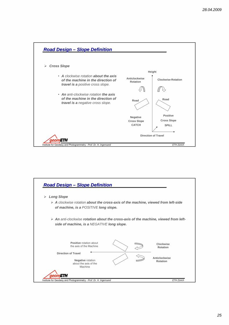
Cross Slope
• A clockwise rotation about the axis of the machine in the direction of travel is a positive cross slope.
• An anti-clockwise rotation the axis of the machine in the direction of travel is a negative cross slope.
Direction of Travel
Clockwise RotationAnticlockwise Rotation
Road Road
Negative Cross Slope
CATCH
Positive
Cross Slope
SPILL
Road Design Road Design –– SlopeSlope DefinitionDefinition
Height
ETH ZürichInstitute for Geodesy and Photogrammetry - Prof. Dr. H. Ingensand
Long SlopeA clockwise rotation about the cross-axis of the machine, viewed from left-side of machine, is a POSITIVE long slope.
An anti-clockwise rotation about the cross-axis of the machine, viewed from left-side of machine, is a NEGATIVE long slope.
Direction of Travel
Positive rotation about the axis of the Machine
Negative rotation about the axis of the
Machine
Anticlockwise Rotation
ClockwiseRotation
Road Design Road Design –– SlopeSlope DefinitionDefinition
28.04.2009
26
ETH ZürichInstitute for Geodesy and Photogrammetry - Prof. Dr. H. Ingensand
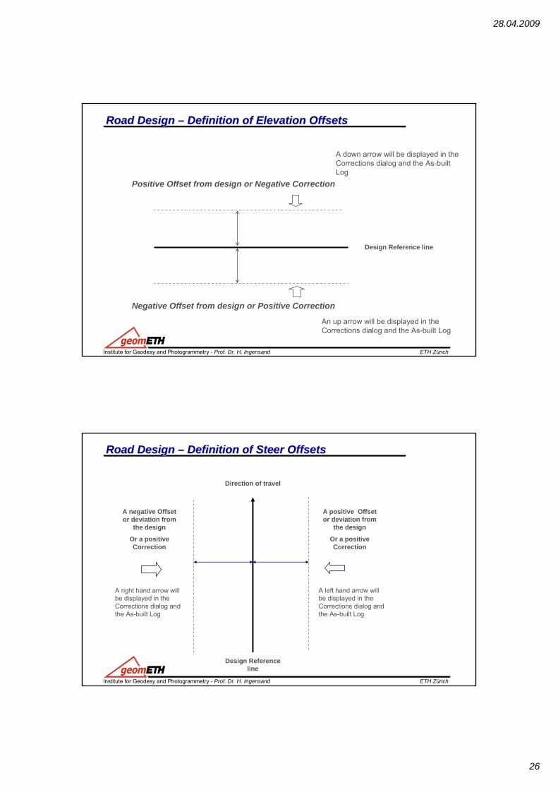
Road Design Road Design –– Definition of Elevation Offsets Definition of Elevation Offsets
Positive Offset from design or Negative Correction
Negative Offset from design or Positive Correction
A down arrow will be displayed in the Corrections dialog and the As-built Log
An up arrow will be displayed in the Corrections dialog and the As-built Log
Design Reference line
ETH ZürichInstitute for Geodesy and Photogrammetry - Prof. Dr. H. Ingensand
Road Design Road Design –– Definition of Steer Offsets Definition of Steer Offsets
A right hand arrow will be displayed in the Corrections dialog and the As-built Log
Design Reference line
A negative Offset or deviation from
the design
Or a positive Correction
A left hand arrow will be displayed in the Corrections dialog and the As-built Log
A positive Offset or deviation from
the design
Or a positive Correction
Direction of travel
28.04.2009
27
ETH ZürichInstitute for Geodesy and Photogrammetry - Prof. Dr. H. Ingensand
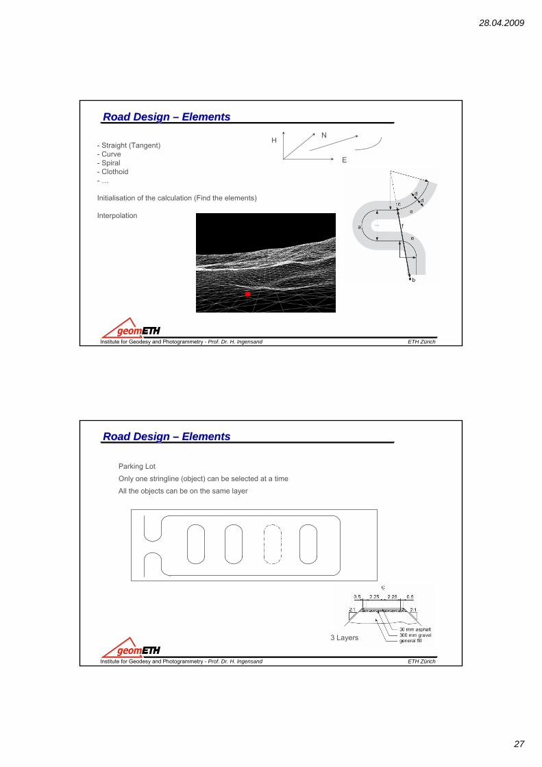
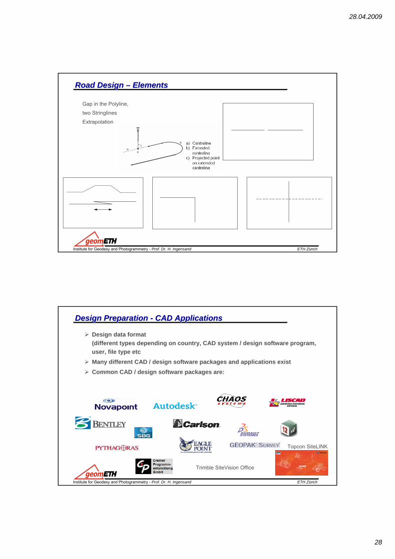
Road Design Road Design –– ElementsElements
- Straight (Tangent)- Curve- Spiral- Clothoid- …
Initialisation of the calculation (Find the elements)
Interpolation
E
NH
ETH ZürichInstitute for Geodesy and Photogrammetry - Prof. Dr. H. Ingensand
Parking Lot
Only one stringline (object) can be selected at a time
All the objects can be on the same layer
Road Design Road Design –– ElementsElements
3 Layers
28.04.2009
28
ETH ZürichInstitute for Geodesy and Photogrammetry - Prof. Dr. H. Ingensand
Gap in the Polyline,
two Stringlines
Extrapolation
Road Design Road Design –– ElementsElements
ETH ZürichInstitute for Geodesy and Photogrammetry - Prof. Dr. H. Ingensand
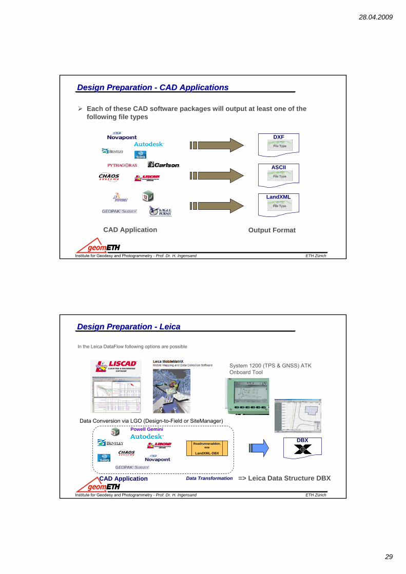
Design Design Preparation Preparation -- CAD ApplicationsCAD Applications
Design data format(different types depending on country, CAD system / design software program, user, file type etcMany different CAD / design software packages and applications exist Common CAD / design software packages are:
Topcon SiteLINK
Trimble SiteVision Office
28.04.2009
29
ETH ZürichInstitute for Geodesy and Photogrammetry - Prof. Dr. H. Ingensand
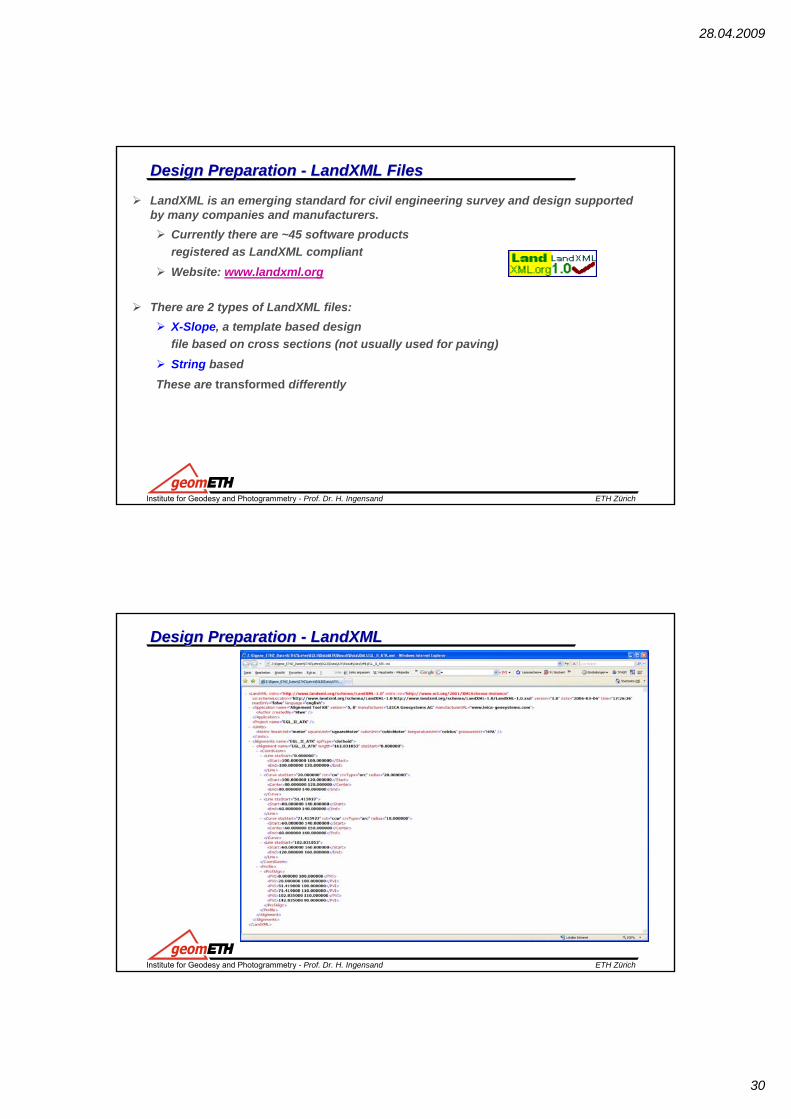
Each of these CAD software packages will output at least one of the following file types
DXF
LandXML
ASCII
CAD Application Output Format
Design Design Preparation Preparation -- CAD ApplicationsCAD Applications
ETH ZürichInstitute for Geodesy and Photogrammetry - Prof. Dr. H. Ingensand
Design Design Preparation Preparation -- LeicaLeica
In the Leica DataFlow following options are possible
System 1200 (TPS & GNSS) ATKOnboard Tool
Data Conversion via LGO (Design-to-Field or SiteManager)
=> Leica Data Structure DBX
Powell Gemini
DBXRoadrunneraddon.
exe
LandXML-DBX
CAD Application Data Transformation
28.04.2009
30
ETH ZürichInstitute for Geodesy and Photogrammetry - Prof. Dr. H. Ingensand
Design Design Preparation Preparation -- LandXMLLandXML FilesFiles
LandXML is an emerging standard for civil engineering survey and design supported by many companies and manufacturers.
Currently there are ~45 software products registered as LandXML compliantWebsite: www.landxml.org
There are 2 types of LandXML files:X-Slope, a template based design file based on cross sections (not usually used for paving)String based
These are transformed differently
ETH ZürichInstitute for Geodesy and Photogrammetry - Prof. Dr. H. Ingensand
Design Design Preparation Preparation -- LandXMLLandXML
28.04.2009
31
ETH ZürichInstitute for Geodesy and Photogrammetry - Prof. Dr. H. Ingensand
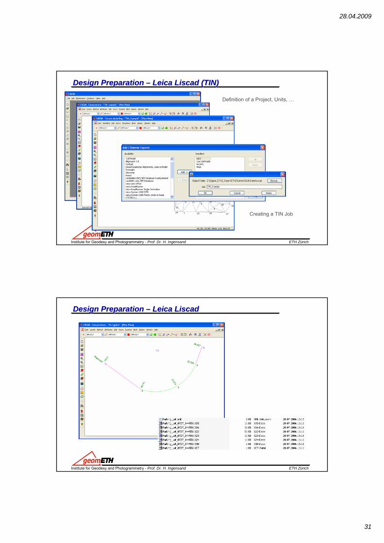
Design Design Preparation Preparation –– Leica Leica LiscadLiscad (TIN)(TIN)
Definition of a Project, Units, …
Creating a TIN Job
ETH ZürichInstitute for Geodesy and Photogrammetry - Prof. Dr. H. Ingensand
Design Design Preparation Preparation –– Leica Leica LiscadLiscad
Related Documents
![01 Introduction.ppt [Kompatibilitätsmodus]webarchiv.ethz.ch/geometh-data/student/eg1/2009/01_Introduction.pdf · surveying (Geometerpatent) Engineering Geodesy - Prof. Dr. H. Ingensand](https://static.cupdf.com/doc/110x72/605cac50efff0a77ec63c26b/01-kompatibilittsmoduswebarchivethzchgeometh-datastudenteg1200901introductionpdf.jpg)