RNP AR in Sweden Christer Ullvetter Senior Adviser OPS & NAV Swedish Transport Agency Aviation department (CAA Sweden) EASA RNP AR workshop 2010-10-20 1

Welcome message from author
This document is posted to help you gain knowledge. Please leave a comment to let me know what you think about it! Share it to your friends and learn new things together.
Transcript

RNP AR in Sweden
Christer Ullvetter
Senior Adviser OPS & NAV
Swedish Transport Agency
Aviation department
(CAA Sweden)
EASA RNP AR workshop 2010-10-20
1
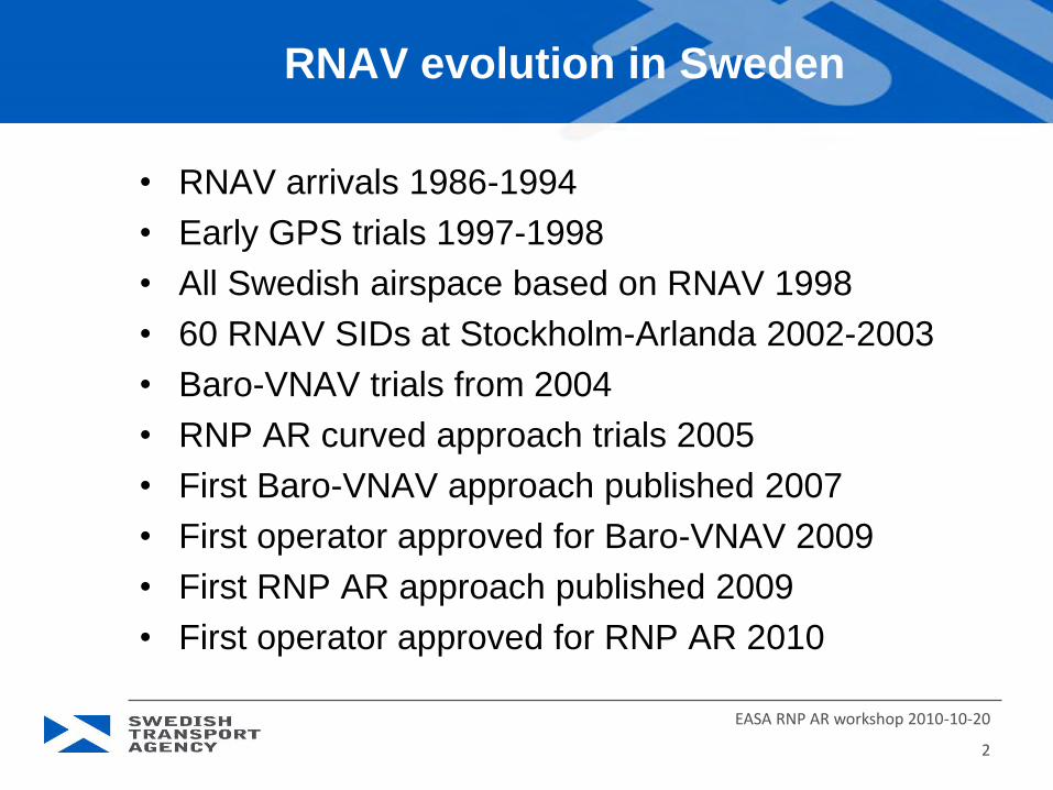
RNAV evolution in Sweden
• RNAV arrivals 1986-1994
• Early GPS trials 1997-1998
• All Swedish airspace based on RNAV 1998
• 60 RNAV SIDs at Stockholm-Arlanda 2002-2003
• Baro-VNAV trials from 2004
• RNP AR curved approach trials 2005
• First Baro-VNAV approach published 2007
• First operator approved for Baro-VNAV 2009
• First RNP AR approach published 2009
• First operator approved for RNP AR 2010
2
EASA RNP AR workshop 2010-10-20

RNAV arrivals to ILS LOC
• CAA cooperation with SAAB 340 operator Swedair
led to trials with RNAV arrivals to ILS LOC
• After one year’s trials the procedure was approved
for operational use 1986
• Later two more RNAV arrivals were approved
• The procedure was based on the use of RNAV
equipment King KNS-660 with sensors:
• DME/DME with high accuracy
• VOR/DME with medium accuracy
• OMEGA/VLF always failed when most needed (Canada)
• Optional GPS not useful due to small number of satellites
3
EASA RNP AR workshop 2010-10-20
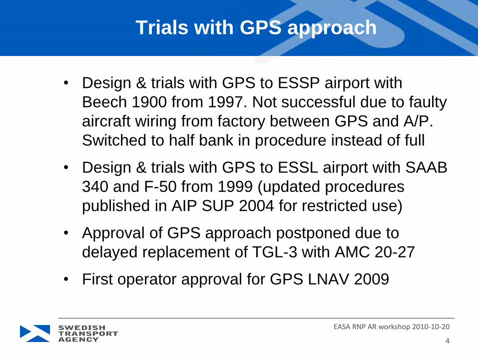
Trials with GPS approach
• Design & trials with GPS to ESSP airport with
Beech 1900 from 1997. Not successful due to faulty
aircraft wiring from factory between GPS and A/P.
Switched to half bank in procedure instead of full
• Design & trials with GPS to ESSL airport with SAAB
340 and F-50 from 1999 (updated procedures
published in AIP SUP 2004 for restricted use)
• Approval of GPS approach postponed due to
delayed replacement of TGL-3 with AMC 20-27
• First operator approval for GPS LNAV 2009
4
EASA RNP AR workshop 2010-10-20

Swedish airspace based on RNAV 1998
• B-RNAV was implemented in ECAC April 1998
• In October 1998, Swedish airspace changed from
old airway system to a B-RNAV based route system
• Several problems were discovered during first day
• Many big air carriers airplane FMS were not updated
• Some pilots had not brought new maps (AIS copied maps)
• Many pilots had not updated their Route Manuals (delays)
• Many company routes were not updated for new airspace
• One incident when a plane suddenly turned 90 degrees to
head for a beacon in Latvia instead of a Swedish VOR
caused by a mistake in manual input of FMS route
5
EASA RNP AR workshop 2010-10-20

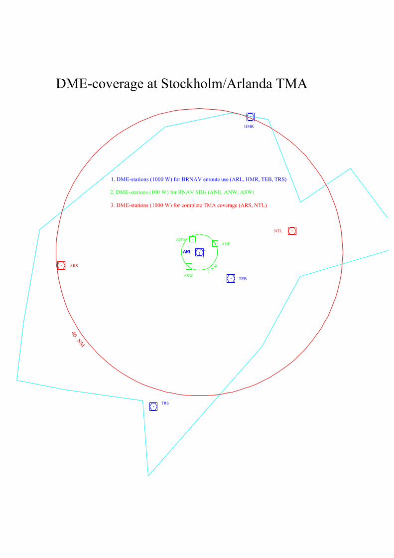
60 RNAV SIDs at Stockholm ESSA
• A new runway should open 2002 and needed 4 new
VORs and 2-3 new NDB beacons
• RNAV based SID/STAR system was investigated,
but SAS MD-80 FMS (without IRS) was not updated
in time to make the first turn in a SID
• With 3 new low-effect DME stations around the
airport, the MD-80s got an early DME/DME update
• Later two new DMEs on the TMA border made
Arlanda to be “probably the best DME-equipped
airport in the world”
6-1.pdf 6-2.pdf
6
EASA RNP AR workshop 2010-10-20
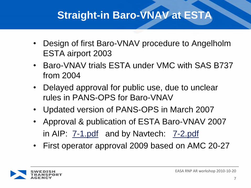
Straight-in Baro-VNAV at ESTA
• Design of first Baro-VNAV procedure to Angelholm
ESTA airport 2003
• Baro-VNAV trials ESTA under VMC with SAS B737
from 2004
• Delayed approval for public use, due to unclear
rules in PANS-OPS for Baro-VNAV
• Updated version of PANS-OPS in March 2007
• Approval & publication of ESTA Baro-VNAV 2007
in AIP: 7-1.pdf and by Navtech: 7-2.pdf
• First operator approval 2009 based on AMC 20-27
EASA RNP AR workshop 2010-10-20
7

TA602
TA601
RW32
TA602TA601 RW32
6381x147ft
768
217
847
Hoganas
417 AH
ESMH
0 1 2 3 4 5 6 7 8 9 10 12 13
314°
Climb on 314° to ,
699
14 15
10
20
11
234
turn right to 417 AH
312°
132°
3.8
6
nm
Change:
3°climbing to .
TCH 50
RNAV RWY 32 RNP 0.3P
AN
S O
PS
ANGELHOLMSweden - ESTA / AGH22 MAY 09
360
180
ARP
Angelholm TMA TWR
RW32
2E
E012 40 E012 50 E013 00 E013 10
N56
N56
10nm
RNAV FAT ° THR Elev AD Elev TL TA
LDA 1945x45
P 3° (54)
420
TA602 N56 10.1 E013 04.0TA601 N56 12.8 E012 59.3
RW32 N56 17.1 E012 52.0
with GNSS and IRS required.For details see reverse side.
Nav
tech
EA
G -
IALS
Min
1200
2000
314°
2000
WPT Coordinates
IAF
2000
50 - 5
18 19
132.45 127.1
MAPt
NOT TO BE USED BELOW -20°C1200
314 52 60 ATC 5000
Approval for Baro VNAV
EU
OP
S
ACFT
C
D
(350)
1200m
GS
ROD 3.0°FAF-MAPt
100
530
120
640
140
740
160
850
Not Authorised
THR 3.0°ALT
65432
A/B
(RNP 0.3)32
esta
05ia
ip00
Min
0.9
4002000169013701060
740400
LNAV/VNAV

RNP AR approach trials at ESGG
• Design of an RNP AR arrival for Gothenburg
ESGG airport started 2009
• Two RF turns lead in to an Baro-VNAV approach
from 1000 ft 8.1.pdf
• Trial flights in VMC started 2010 with Novair A321
• Today 50 successful flights have been completed
• Goal for this project is 100 flights
• Benefit is a 3 min shorter flight, 150 kg less fuel
burn and 500 kg less CO2 emissions
• 8.2 Novair A321.ppt
EASA RNP AR workshop 2010-10-20
8


RNP AR Operation
Novair A321
Error sources associated with RNAV operation
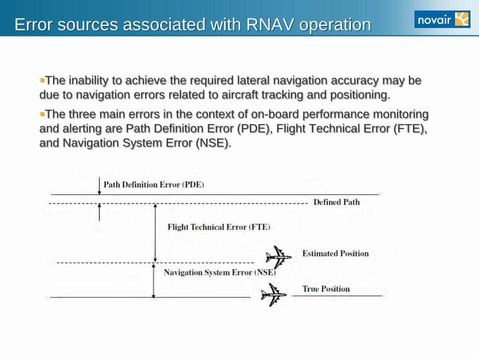
The inability to achieve the required lateral navigation accuracy may be
due to navigation errors related to aircraft tracking and positioning.
The three main errors in the context of on-board performance monitoring
and alerting are Path Definition Error (PDE), Flight Technical Error (FTE),
and Navigation System Error (NSE).

Path Definition Error (PDE) occurs when the path defined in the RNAV
system does not correspond to the desired path, i.e. the path expected to be
flown over the ground. The PDE has been demonstrated negligible, provided
there is no systematic error such as navigation database coding error or error
due to inadequate geodetic reference (other than WGS84).
Flight Technical Error (FTE) is a characteristic of the pilot performance
using FD or AP guidance performance in the steering of the aircraft on the
FMGS defined flight path.
Navigation System Error (NSE) is the error made by the navigation
system in the computation of the aircraft position. The NSE has a circular
statistical distribution around the aircraft true position. From this circular
distribution, it is possible to derive a cross-track component of the NSE,
which is relevant for the RNP lateral navigation.
Error sources associated with RNAV operation

Estimated Position Error (EPE)
EPE: The FMGC position is estimated with a 95 % probability to be within
a circle of uncertainty. The estimated circle radius is shown on the
PROGRESS page in the MCDU. By comparison of REQUIRED value
with ESTIMATED value, the system determines a HIGH/LOW accuracy
level.
Radius
95 %
Probability

EPE (Estimated Position Error) is a radial estimation of the navigation
error and is more conservative than the statistically demonstrated NSE.
Estimated Position Error (EPE)
EPE
NSE
NSE≤ EPE
RNP Crew Alerting
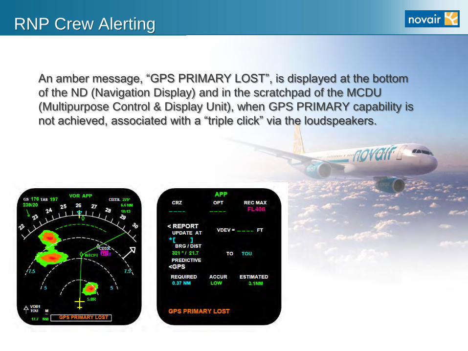
An amber message, “GPS PRIMARY LOST”, is displayed at the bottom
of the ND (Navigation Display) and in the scratchpad of the MCDU
(Multipurpose Control & Display Unit), when GPS PRIMARY capability is
not achieved, associated with a “triple click” via the loudspeakers.

RNP Crew Alerting
There is no automatic callout or alert when the FTE exceeds the budget
allocated to ensure that the RNP is achieved. To be monitored by crew.
(Extreme winds in the simulator is needed to generate this exceedance)
The FTE = XTK = 0,2 L NM

GNSS Navigation
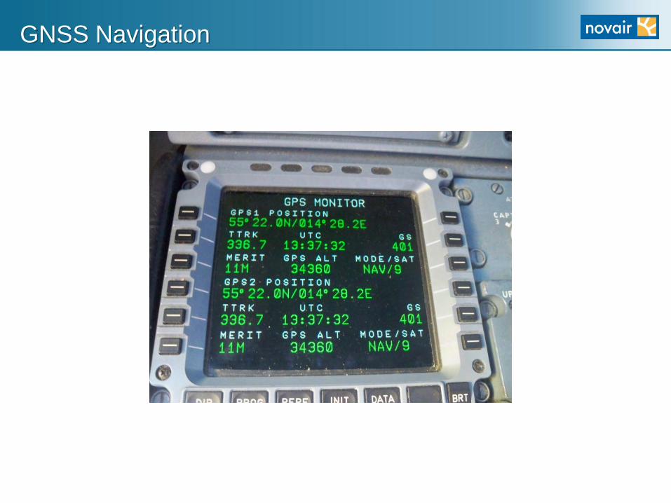
RNP AR approaches are
only authorised based on
GNSS as the primary
navaid infrastructure.
RADIONAV to be deselected in order to
use GPS/IRS as sole
navigation source.
GNSS Navigation

OSNAK 1X transition to RNAV (RNP) ESGG RWY21

After OSNAK (TMA entry point)

After IAF
RNP = 0,3
EPE typically 0,08
Flight guidance prior to FAP
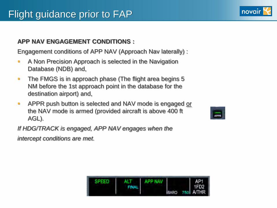
APP NAV ENGAGEMENT CONDITIONS :
Engagement conditions of APP NAV (Approach Nav laterally) :
A Non Precision Approach is selected in the Navigation
Database (NDB) and,
The FMGS is in approach phase (The flight area begins 5
NM before the 1st approach point in the database for the
destination airport) and,
APPR push button is selected and NAV mode is engaged or
the NAV mode is armed (provided aircraft is above 400 ft
AGL).
If HDG/TRACK is engaged, APP NAV engages when the
intercept conditions are met.

Flight guidance prior to FAP
APP NAV is identical to NAV mode in terms of logic and performance

Flight guidance after FAP
FINAL APP on the FMA (Flight Mode Annunciator)
Each dot represents 100 feet

RNP AR ESGG
Left base RWY21 ESGG 3 NM final RWY21 ESGG

THANKS TO NOVAIR
For questions, contact
Flight Captain Henrik Ekstrand
Performance & Ecology Manager
e-mail: [email protected]
mobile: + 46 708 87 02 08

Problems with Stockholm ESSA new rwy
• Was built too close to noise sensitive area
• Environment court has decided no flights allowed
to fly over sensitive area from year 2018 9.1.pdf
• Was planned for a curved MLS approach, but no
MLS is used for curved approach (risk of pilot error
when entering turn data into the MLS system)
• New plan for a VOR approach with a 25º turn at
400-500 ft was OK, until ICAO reduced the turn to
be max 15º (30º was allowed in old PANS-OPS)
• An offset LOC was tested in SIM for 15º turn at
500 ft. The result – not OK at night in low visibility !
EASA RNP AR workshop 2010-10-20
9


Solution for ESSA is RNP AR
EASA RNP AR workshop 2010-10-20
10
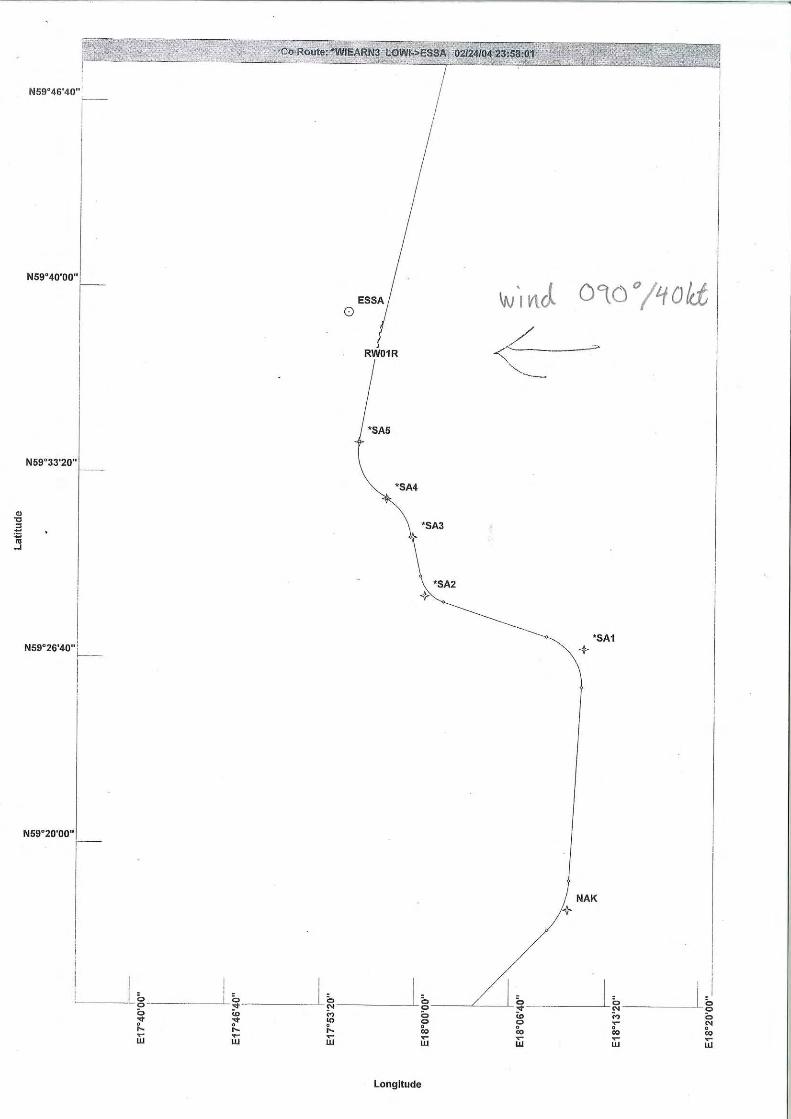
• RF leg coding developed for B737 in Smiths’ PDT
(Procedure Design Tool for standard PC). Good
result for heavy airplane in 40–50 knots crosswind
• Coding: 10.1.pdf and plotting: 10.2.pdf
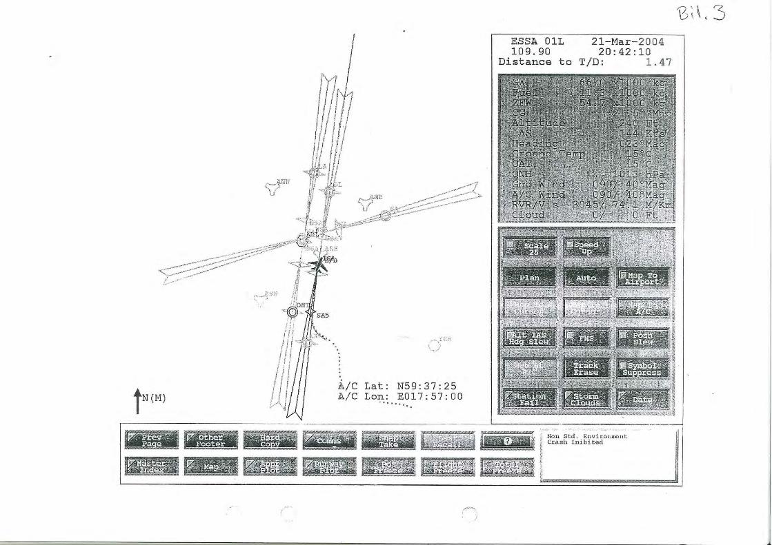
• SIM trials 2004: 10.3.pdf and plotting: 10.4.pdf
• 5 production flight trials in VMC 2005: 10.5.pdf
• 4 years waiting for ICAO RNP AR Procedure Design
Manual (Doc. 9905). Draft Nov 2007 & 1st ed. 2009
• Lateral procedure: 10.6.pdf and vertical: 10.7.pdf
• Publication of ESSA RNP AR 2009 in AIP: 10.8.pdf
and by Navtech: 10.9.pdf


1
1
2
2
3
3
8202x147ft
SA693
SA694
SA696SA697
RW01R
SA695
SA689
SA691
SA692
253
263
263319
246
181
453
Kungsangen1600PPR
A
B
C
10nm
114.45 ASE 040°
D1 ASE
DME
R16
RAD vectors for new APCH.
Climb on 006°. At or
Change:
PA
NS
OP
S
RNAV FAT ° THR Elev AD Elev TL TA
5E
FA
LS
LDA 2500x45
P 3°R (57)
Stockholm APP GND DLV (D) ATIS ARR (D)Arlanda TWR
RWY 01R/19L
RWY 01L/19R, CTR West
RWY 08/26, CTR East
see proc on IAC 10
090 27036
0ARP
MAX 210kt
MAX 190kt
286° 5.7240°
22.7
241°36
0°
31.3
037°
212°
44.2
178°
7.1
7.1
HMR
XIL
AN
TRS
30
40
E017 50 E018 00 E018 10 E018 20 E018 30
N59
N59
STOCKHOLMArlanda
Sweden - ESSA / ARN25 AUG 10
7.5
Rev
erse
sid
e bl
ank
2.32.1
2.6
Scale distorted
Noisesensitivearea
MAX 175kt
012345678910111213nm
RW01RSA697SA696SA695
006°
3°
SeeChart
RW01R
Nav
tech
-
RNAV (RNP) RWY 01R
Baro-VNAV Proc NA below -15°C
MNM
MNM
MNM
D1 after ASE whichever,
tclimbing to .is latest, turn right o 040°
Min, spec.
006°
600
600
006 137 137 ATC 5000
123.75 124.1126.65
121.7 121.925121.975
121.825 119.0125.125118.5128.725
In case of COM FAILURE
1500
19
2217
Special Authorization forRNP AR required fromSwedish CAA. Approval for Baro VNAV required.
RNP 0.3 and RF-leg required.
50 - 11
2680
2680
1170
MAPt
IAF
IF
TEMP RESTRICTION
5000
5000
5000
EU
OP
S
ACFT
C
D
(470)
1500m
essa
11ia
ip00
Note: Circling NA
610
LNAV/VNAV RNP 0.3

First RNP AR approval in Sweden
EASA RNP AR workshop 2010-10-20
11
• 5 years waiting for AMC 20-26 (and 20-27)
• Compliance list for 20-26 on request: 11.1.pdf
• SAS B737 RNP indicators: SAS B737 NPS.ppt
• RNP AR approval of SAS 2010
• SAS has now made 100 RNP AR approaches

B737 RNP INDICATORS

FMC RNP values• Cruise - 2,0 nm (default)
• Off route/Oceanic - 5,0/12,0 nm (default)
• TMA <FL150 - 1,0 nm (default)
• Appr - 0,5 nm (default)
• Appr - 0,3 nm (default)
• Appr w F/D - 0,15 nm
• Appr w A/P - 0,11 nm
• Appr w F/D or A/P - 0,10 nm (NPS req.)

Navigation Source
LNAV/VNAV is displayed as
navigation source when either
AFDS (Autopilot Flight Director
System) LNAV or VNAV mode is
engaged
ILS
ILS is displayed as navigation
source when APP or LOC is
armed or active.

Navigation Performance Scales (NPS)Magenta Deviation pointer:
Indicate lateral path relative to
the airplane. (X-track error)
White ANP bar indicates Actual
(estimated) Nav Performance.
If the ANP value increases, the
ANP bars extend towards the
centre indicator
White vertical index has a fixed
position and represents current
FMC lateral RNP

Lateral NPS on PFD (Primary Flight Display)
When entering airspace with
different RNP, the new RNP is
displayed on the MCDU (Multi-
function Control & Display Unit)
The RNP approach value (0.3)
is automatically set as the
FMC approaches the FAP or
at a point programmed
in the Nav Data Base
RNP / ACTUAL -------------------------
0.30/0.15NM RTE DATA>
Deviation pointer sensitivity is
changed
Room for manoeuvre changes
with current ANP value

XTK Deviation (Flight Technical Error)
As long as the NPS pointer is
within the manoeuvrable area
(RNP–ANP = manoeuvrable area),
the ANP Bars are white
If the NPS pointer enters the ANP
Bar, the scales turn AMBER after
10 seconds and the NPS pointer
start to flash at the same time.
If inside FAP: perform a missed
approach as soon as the NPS
pointer touch the ANP Bar

Navigation Performance Scales
RNP
Low ANP
value
Increased ANP
value
High ANP
value
X-Track Error
RNP / ACTUAL -------------------------1.00/0.75NM RTE DATA>
RNP / ACTUAL -------------------------1.00/0.25NM RTE DATA>
RNP / ACTUAL -------------------------1.00/0.05NM RTE DATA>
RNP / ACTUAL -------------------------1.00/0.75NM RTE DATA>

Vertical NPS on PFD
White Vertical ANP
Bars indicate vertical
ANP the same way as
lateral ANP
Magenta Vertical
NPS pointer indicates
vertical path relative
to the airplane
Vertical RNP default
value is 400 feet.
Can be manually
changed in FMC

Indications on Navigation Display (1)
White Path Deviation Band is a fixed line which always represents 400 ft
Magenta Vertical Deviation Band, with a fixed pointer in the centre, represents the chosen RNP value. Here the value is set to 400 ft
White triangle is airplane position.
Here the XTK error is 1.8 L
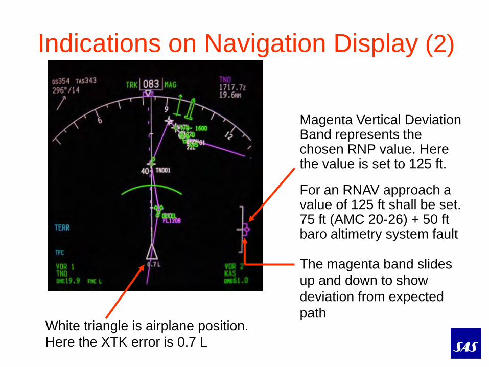
Indications on Navigation Display (2)
Magenta Vertical Deviation Band represents the chosen RNP value. Here the value is set to 125 ft.
For an RNAV approach a value of 125 ft shall be set. 75 ft (AMC 20-26) + 50 ft baro altimetry system fault
White triangle is airplane position.
Here the XTK error is 0.7 L
The magenta band slides
up and down to show
deviation from expected
path

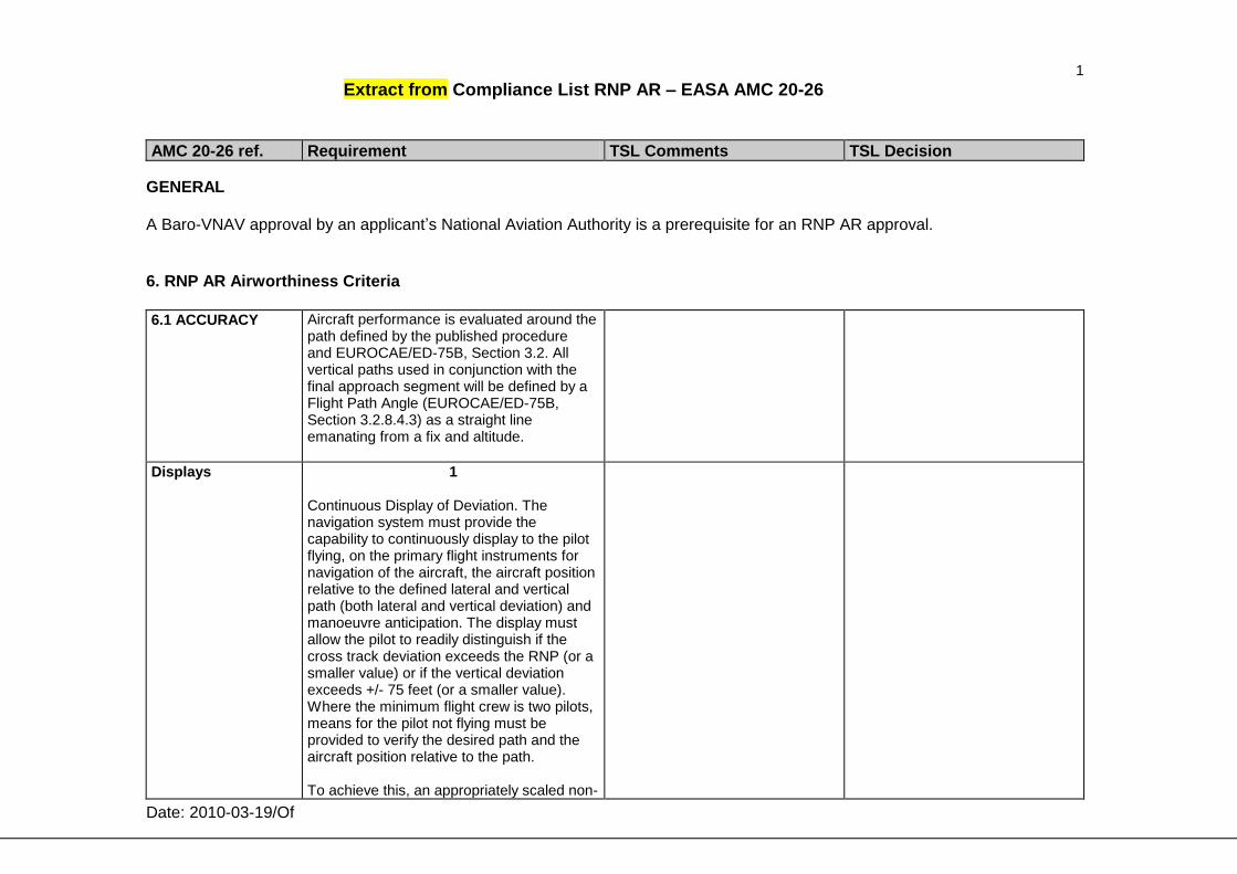
1 Extract from Compliance List RNP AR – EASA AMC 20-26
AMC 20-26 ref. Requirement TSL Comments TSL Decision
Date: 2010-03-19/Of
GENERAL A Baro-VNAV approval by an applicant’s National Aviation Authority is a prerequisite for an RNP AR approval.
6. RNP AR Airworthiness Criteria
6.1 ACCURACY
Aircraft performance is evaluated around the path defined by the published procedure and EUROCAE/ED-75B, Section 3.2. All vertical paths used in conjunction with the final approach segment will be defined by a Flight Path Angle (EUROCAE/ED-75B, Section 3.2.8.4.3) as a straight line emanating from a fix and altitude.
Displays
1 Continuous Display of Deviation. The navigation system must provide the capability to continuously display to the pilot flying, on the primary flight instruments for navigation of the aircraft, the aircraft position relative to the defined lateral and vertical path (both lateral and vertical deviation) and manoeuvre anticipation. The display must allow the pilot to readily distinguish if the cross track deviation exceeds the RNP (or a smaller value) or if the vertical deviation exceeds +/- 75 feet (or a smaller value). Where the minimum flight crew is two pilots, means for the pilot not flying must be provided to verify the desired path and the aircraft position relative to the path. To achieve this, an appropriately scaled non-

2 Extract from Compliance List RNP AR – EASA AMC 20-26
AMC 20-26 ref. Requirement TSL Comments TSL Decision
Date: 2010-03-19/Of
numeric deviation display (i.e. lateral deviation indicator and vertical deviation indicator) located in the pilot’s primary field of view may be provided. Alternatively: For lateral data presentation only For RNP 0.3 and above, - a navigation map display, readily visible to the flight crew, with appropriate map scales, giving equivalent functionality to an appropriately scaled non-numeric lateral deviation display, except that scaling may be set manually by the flight crew. or - a numeric display of the lateral deviation, readily visible to the flight crew, with a minimum resolution of 0.1 NM and direction relative to the track. For RNP <0.3 - a numeric display of the lateral deviation, in the primary field of view, with a resolution of 0.01 NM and direction relative to the track Note 1: A fixed-scale CDI is acceptable as long as the CDI demonstrates appropriate scaling and sensitivity for the intended navigation accuracy and operation. With a scalable CDI, the scale should be derived from the selection of RNP, and shall not require the separate selection of a CDI scale. Where a CDI is relied upon, alerting and annunciation limits must also match the

3 Extract from Compliance List RNP AR – EASA AMC 20-26
AMC 20-26 ref. Requirement TSL Comments TSL Decision
Date: 2010-03-19/Of
scaling values. If the equipment uses default navigation accuracy to describe the operational mode (e.g. en-route, terminal area and approach), then displaying the operational mode is an acceptable means from which the flight crew may derive the CDI scale sensitivity.
Video from a SAS flight 2005
• In the video from 2005, the arrival from the north
was not the same as today (RF turns not changed)
• The video will be stopped to view indicators
• Captain Orjan Goteman in the left seat has since
been a PhD with a doctoral thesis on:
“Airborne Cognitive Systems in Search of an
Appropriate Context” 12.1.pdf
• The “sweaty” pilot in the right seat is now SAS
Director Flight Operations
• Conclusion: Work with RNP AR procedures,
and your life will be successful !
EASA RNP AR workshop 2010-10-20
12


RNP AR in Sweden
Christer Ullvetter
Senior Adviser OPS & NAV
E-mail: [email protected]
Mobile: +46 708 19 23 12
EASA RNP AR workshop 2010-10-20
13
Related Documents