*** RMIS View/Print Document Cover Sheet *** This document was retrieved from the Documentation and Records Manaqement (DRM) ISEARCH System, It is intended for Information only and may not be the most recent or updated version. Contact a Document Service Center (see Hanford Info for locations) if you need additional retrieval information. Accession #: D196229548 Document # WHC-SA-3024-FP Title/Desc: REPORT ON THE DESIGN OF FREEZE PROTECTION FOR HANFORD NUCLEAR RESERVATION FIRE SUPPRESSION SYS Pages: 35

Welcome message from author
This document is posted to help you gain knowledge. Please leave a comment to let me know what you think about it! Share it to your friends and learn new things together.
Transcript

*** RMIS View/Print Document Cover Sheet ***
This document was retrieved from the Documentation and RecordsManaqement (DRM) ISEARCH System, It is intended for Informationonly and may not be the most recent or updated version. Contact aDocument Service Center (see Hanford Info for locations) if you needadditional retrieval information.
Accession #: D196229548
Document # WHC-SA-3024-FP
Title/Desc:REPORT ON THE DESIGN OF FREEZE PROTECTION FORHANFORD NUCLEAR RESERVATION FIRE SUPPRESSION SYS
Pages: 35

WHC-SA-3024-FP
Report on the Design of FreezeProtection for Hanford NuclearReservation Fire SuppressionSystems
S. M. Korslund
Date Published
February 1996
To Be Presented at
DOE Fire Protection Conference
Chicago, Illinois
April 29-May 2, 1996
Prepared for the U.S. Department of EnergyAssistant Secretary for Environmental Management
Westinghouse P.O BOX 1970Hanford Company Richland, Washington
Management and Operations Contractor for theU.S. Department of Energy under Contract DE-AC06-8VRL10930
i By eooBptance of tha arbda. the pubiahar and /or iwapMnt acknowWffw * •U S Govamment'i nght to retan * nonnctuanro, royatv-free ictnae In and to any oopynght covanhg thai papar
Approved for public release; distribution is unlimited

Data Received byIIMFORMATION RELEASE REQUEST - (Long Form)
(GRAY SHADED AREAS NOT TO BE FILLED IN BY INITIATOR)
1. COMPLETE THIS SECTION FOR ALL DOCUMENTS
A Information Category
Speech or Presentation I
[J] Full Paper j
r~\ Summarv j
Q Abstract '
Q Visual Aid
Journal Article
Multimedia Presentation
Software
Other
B, Document ID Number (include rev vol , etc!
WHC-SA-3O24-FP, REV. 0
C List attachments |i e , copyright permiision copynght transfer)
DATA SHEET FOR RTD-G ROOM TEMPERATURE DETECTOR DATA SHEETFOR RTD SERIES ROOM TEMPERATURE DETECTOR DATA SHEET FOR RTSROOM TEMPERATURE DETEC1OR FS-OO25; PROCEDURE FOR PROGRAMMINGAND TESTING, BILL OF MATERIAL, CVI 12244, SHEET 69
D Document Title
REPORT ON THE DESIGN OF FREEZE PROTECTION FOR THE HANFCRD NUCLEARRESERVATION FIRE SUPPRESSION SYSTEMS
E. WHC Project or Program
PSS/HFD/FP
F New or novel I patent able) subject matter?If "Yes" has disclosure bean submitted by WHC?
\ \ No or Ves If "Vet" Disclosure No(t|
No or YesG Information received from others in confidence such as proprietary data
and/or inventions?
No or Vet If "Ves", contact WHC General Counsel
H Copyrights? ND or Yes If "Yes" attach permission I Trademarks? No or Yes If "Vet* identify in document
2 COMPLETE THIS SECTION FOfl ALL DOCUMENTS REQUIRING SUBMISSION TO OSTI
<\ Unclassified Category UC - 630 B. Budget & Fe port ing Code B&R - YN01000003 COMPLETE THIS SECVON ONL r FOR A JOURNAL SUBMISSION
A Title of Journal
4 COMPLETE THIS SECVON ONL V FOR A SPEECH OR PRESENTATION
A Title tor Conference or Meeting
DOE FIRE PROTECTION CONFERENCEB Group at Society Sponsonng
DOE FIRE PROTECTION GROUPC Date|s) of Conference
or Meeting
4/29/96-5/02/96
D City/State
CHICAGO, ILLINOIS
E Will materiel be published in proceedings? \j£j No or Ves
Will matenul be handed out? [JJ No or Yas
5 REVIEWS
Signature indicates Approval a* Requested unlens otherwise IndicatedVes Name (print) Signature/Date Limited-Use Info
General Counsel
DOERL
Communications
Applied TechnoloQ^-Enport Controlled j—i
ion or International Praaram L_J
Other
Other
n•
6 Applied Technology Materiel Referenced
7 Release Level
Public J_J Limited Distribution
8 Author/Requestor
STEVEN M KORSLUND(Print and Sign) Date
3 Responsible Manager
W (MAC) h NIGHT(Print and Stgnl
WFORMA VON RELEASE ADMINISTRATION APPROVAL
fftA Approval n required before release Release is contingent upon resolution ofmandatory comment* NOTE: This block for WA u u only
Date Cancelled Date Disapproved
A-6OO1-401 (07/94)

WHC-SA-3024-FP, REV. 0Document 10 Number
W LEGENDSsMOWCES/MARKINGS {Required by WHC-CM-3-4 or Reviewer). Reviewer indicates applicable marking! to be affixed or removed.
Aff ix Remove
D •• •• •• •• •• •• •• D
.* • •
Applied Technology
Availability - OSTI
Avail abilrty - ESTSC
Availability - NTIS
BiisirtBS(-5ensitiV0 Information
Computer Software Notice
Copyright Licenae Notice
Export Controlled Information
Legal Disclaimer
Limited DisclotuTe
Officul Use Only
Patent Status
Pmdsctstonat Information
Programmatic Notice
Proprietary Information
Purpoie and Use
Them O*«»ert«ton
Traderurfc Disclaimer
Other
f MANDATORY COMMENTS { b i t onry mandntory comments horeAll other comments ehall be mad* on the document and returnedto the author |
An, trademarked item must be 1| replaced bva generic equivalent 2) noted as a trademarkthe l int time used e g "Trademark of
" eithei in the te*t or as a footnote1 or2\ listed elsen-herc in the document e g
I I a t ademark of
Reviewer(Print & Sfgnl Date
Resolved bj*Author/RequestorIPflnt & Sign!
JDate
II ADDITIONAL INFORMATION, COMMENTS.
d
A7 1
A 6O01-401R (07/941

S2/9F3>1M2 15#
comb., * . Pre,K,u.
U - S - DEPARTMENT OF ENERGY gJ^No.RECOMMENDATIONS FOR THE ANNOUNCEMENT AND DISTRIBUTION * ?
OF DEPARTMENT OF ENERGY {DOE) SCIENTIFIC AND TECHNICAL INFORMATION {STI)16 All other
editions are obsoleteStatement on
' £ ' e e instructions on reverse side Use plain bond paper if additional space is needed for explanations! reverse side
P A R T 1 (DOE, DOE Contractors, Grantees, and Awardees complete!
A. Product/Report Data1. (Amardl Contract No. DE-ACQ6-87RL1 0930
c Software - Additional forme are required Follow instructions on theback of this farm.
2. T.ti« Report on the Design of FreezeProtection for Hanford Nuclear ReservationFire Suppression Systems
{ ] d Othar fProntfe complete description!
3 Product/Report Descriplion
Q a Report (Complete all that apply!
I'll Q Print Q Nonprint (specify!
[2\ ]_J Quarterly f_] Semiannual \_j Annual
\ | Topical L J Phase I |_J Phase II
Other (specify!
B. Patent InformationVas N.
F'nal
Is any new equipment, process, or material disclosed?
If yes, identify page numbers
Dates coueied thru
b Conffirence/Meeting/Presentation (Complete all that apply!
HI [XI P rmt O Nonprint (specify!
\l\ Published proceedings
Q Other (specify!
| I
Has an muention disclosure been submitted?
If yes, identify the disclosure number and to whom it was submitted.
Duclosure number
Submitted to
Are there patent-ralated ob|ections to the release of this STI product?
If so state the objections
(2) Conference
DOE F i i
Location <ci
Title
'~e
tv sti
(no abbreviations!
Pr
ite
otection Conference
co^m'Chicaqo, 11C . C o n t a c t (Person knowledgeable of content!
Name S ,. M. Kl
Phone 509-373-1639Date|s]/mWyl 4 / 2 9 / 9 6 thru Im d rl 5 / 2 / 9 6
Sponsor UUt.
position A u t h o r
rganisation Westinghouse Hanford Company
P A R T II (DOE DOE Contractors complete or as instructed by DOE contracting officer!
A. DOE Identifiers1 Product/Report No* WHC~SA-3024-FP
2 Funding Qffice(s) (NOTE. Essential data! EM
B. Copies for Transmittal to AD-21 (OSTI)I STI must be of sufficient quality for microfilming copying I
| 1 I One for classitied piocossinQ
| | 2 {number! for itandard classified distribution
|X) 3 Two unclassified for processinfl
|_ I 4 /number! for program unclassified distribution
\X\ 5 UC/C Category UC- 6 3 0BSR CODE - YN0100000
| [ i Special Handling /Legal basis must be noted below)
f I a Unclassified Controlled Nuclear Information |UCNI|
Q b E.port Control/ITAR/EAR
[_[ c Temporary hold pending patent review
| ] d Translations of copyrighted material
| | e Small Business Innovation Research (5BIR)
[ | f Commercialnable information
| I (1| Proprietary
Q | I2| Protected CPADA information
Release date
Q | (3) Other tetphml
j_J 6 Additional instnjctiDns/e*planationi
(Do not identify Sigma categories for Nuclear Weapons Data reports, and donot provide additional instructions that ate inconsistent with C be/on I
C. Recommendation rx'atkastonet
|X1 1 Program'Standard Announcement/Distribution{Available to U S. end foreign public!
I I 2 Classified (Standard -Announcement only!
| | A. Program Directed Special Handling (copy attached!
D. Releasing OfficialA Patent Clearance ("*" one'
[ | H K been submitted for DOE patent clearance
IXl C*OE patent clearance has been grantedB Releasnd by
KapaBroz
(Date!

WHC-SA-3024-FP Rev. 0
REPORT ON THE DESIGN OF FREEZE PROTECTION FOR HANFORD NUCLEARRESERVATION FIRE SUPPRESSION SYSTEMS
S. M. KorslundFire Systems Administrator, Hanford Fire Department
BACKGROUND
The National Fire Protection Association (NFPA) 72 (1993) requires using temperaturesensing equipment to monitor water supplies for fire suppression and water-based fireextinguishing systems for freezing temperatures based on the requirements of NFPA 13(1994). NFPA 72 also requires that testing of freezing temperature detection equipment toverify that the sensor causes a supervisory signal at 40 degrees Fahrenheit (°F) (± 5 °F).The required test method must ensure operation of the device at 40 °F. NFPA 72requirements and test methods cannot reasonably be interpreted to allow an unmeasuredtemperature lowering agent to cause operation of the device as a valid test of the device.
Commercial Equipment supplied as cold temperature sensors includes a variety of single-point spot detectors described as actuating at 40 °F. However, there is no manufacturer-recommended, field-usable procedure compliant with NFPA 72 that can provide properactuation point verification within the test method requirements of NFPA 72. Themanufacturer does not recommend a suitable test to verify point of actuation, except to placethe detector in a temperature controlled environment and verify that it trips at or higher than40 °F. This test, which consumes time, manpower, equipment and money, is less thansatisfactory,
Cold temperature detection at the Hanford Site is used to monitor the temperature in riserrooms for dry sprinkler systems and to monitor portions cf wet sprinkler systems that passthrough unheated areas.
TEST METHODS
The current, widely used test method is to apply a freezing spray of canned "air" to thedevice. The Hair" consists of 100 percent chlorodiflouromethane, an inert gas. By invertingthe can and releasing the gas propellant, temperatures as low as - 3 0 °F can be obtained.Although this method actuates the device, the extremely low temperature and rapid rate ofdescent do not prove the device actuated at 40 °F. In addition, the possible ill effects of theextreme cold temperature on the device have not been ascertained. These shortcomings havebeen issued as an audit finding by the Department of Energy-Richland Operations. Thefinding cites that NFPA 72 requires room temperature switches be tested to verify that thedevice operates and results in a signal that indicates the room temperature decrease to 40 °Fand restoration to above 40 °F. The Fire Protection Manual (WHC-CM-4-41) for the

WHC-SA-3024-FP Rev. 0
Westinghouse Hanford Company specifies that testing activities for high and low temperatureswitches verity that an alarm occurs within ± 7 percent or 5 °F, whichever is greater, of thedesired setpoint in the direction that the switch would alarm.
It is important to note that single-point devices currently available to the industry are notUnderwaters Laboratory (UL) listed for freeze protection for fire suppression systems. Theymay, however, contain UL listed components.
EXISTING TYPES OF FREEZING TEMPERATURE DETECTORS
The main supplier of freezing temperature detectors has provided three types of devices inrecent years.
The first type was the Model RTD-G, a mercury-thermometer type not available in anormally open configuration to comply with NFPA 72 (1993). For this reason, apparentlythey were discontinued. (ATT. 5)
The second type, designated Model RTD-N.O. or RTD-N.C, operated on the thermistorsemi-conductor principle. The operation of this model psirtially depended on the controlequipment. Because the electrical resistance of the device Lowers as the sensed temperaturedecreases, the control panel determines the point of actuation. It is possible that onemanufacturer or type of control panel would tnp at 50 °F while another would not trip until30 °F. (Hie data sheet for this specific device refers to it as a bimetallic disk, but field testsindicate otherwise.) This potential controversy introduces quality control questions. Thesedevices are no longer available through the fire systems component distributor. (ATT- 7)
The third and currently available type is a simple bimetallic strip, Model RTS-0 or RTS-C.(ATT, 9)
There is no apparent consensus on the construction or mode of operation of these devices.
RECENT TECHNOLOGY
An exception to the poor test ability of cold temperature devices is the recent development ofanalog systems which use linear temperature sensors to supply the control panel withtemperature information. The control panel is programmed to determine whether thecondition sensed is a heat increase within the parameters of a fire alarm device or atemperature decrease within the parameters of an incipient freeze condition. These sensors(detectors) are UL listed for freeze protection for fire alarm suppression systems, but theymust be used with their specific control panel thus precluding universal application.
The lack of UL listed equipment, which can be readily tested to verify the actual point ofactuation has become a nationwide end user concern.

WHC-SA-3024-FP Rev. 0
NEW EQUIPMENT AT THE HANFORD SITE
The Hanford Fire Department Fire Systems Testing and Maintenance Engineering Divisionhas adapted an application using a currently manufactured industrial process temperaturecontroller which fiilly complies with the intent of NFPA requirements including thefollowing:
Supervision of the power supply
Monitoring of sensing circuits
Tests to verify the point of actuation
Programmable to a single point of actuation, with the set point protected fromunauthorized alteration
Readily visible local annunciation with a digital readout of actual detected ormonitored temperature and local indication of off-normal condition
This controller is a Red Lion Model TCU temperature controller with an optional relayoutput that connects to a local fire alarm control panel. The relay provides normally opencontacts for systems in compliance with NFPA 72 (1993) and normally closed contacts forsystems complying with earlier codes of record.
A supervisory (off-normal) signal is generated when there is an open circuit or shortedcircuit for the sensing element, loss of primary power, or a temperature lower than deviceset point.
The Hanford Fire Department Fire Systems Testing and Maintenance Engineering Divisionwrote procedure FS-0025 to program and test the unit. This procedure is attached to thisarticle for information purposes.
The controller can be installed in approximately four hours. The cost of materials isapproximately $275.
The temperature controller includes a 5 amp fuse housed in a safe electrical inline fuseholder. The fuse holder pulls apart with the energized portion insulated and shielded fromaccidental contact in compliance with 29 CFR 1910 for j»ersonnel protection duringmaintenance.
The Hanford Nuclear Reservation has installed 70 of these systems in 55 locations with azero failure rate during the first six months of operation. The ability of these systems todetect a failure in the area or pipe heating system prior to dropping to 40 °F is an addedbenefit. A surveillance program can monitor and track ihe sensed temperature duringinclement weather as it continually displays on the digital readout.

WHC-SA-3024-FP Rev. 0
The Red Lion Company has been contacted about submilting the Model TCU unit to UL forlisting for freeze protection for fire suppression systems. The high quality unit is UL listedas a temperature monitor and controller for industrial and process control applications.Another model, whose design is under consideration, would receive power directly from afire control panel and could operate as a supervisory initiating device. This would be similarto operating an alarm initiator that requires separately derived 24 vdc power, such as a ductsmoke detector.
NEW TEST METHOD
The Hanford procedure for testing the Red Lion unit compares the sensed temperaturereading with the programmed set point. Both temperature readings display, one above theother in a digital format. A front panel button is used to raise the set point to .2 °F abovethe sensed temperature, at which time the receipt of the supervisory signal is verified.Therefore, by interference, the sprinkler system is protected at the set point level of 40 °F.The set point is programmed to prevent the temperature jxom being lowered below 40 °F,and it can be password protected. Leaving the set point raised provides a higher degree ofprotection. See Attachment 11 for the formal programming and testing procedure.
COMPARING TEST COSTS
The previous test method required two persons: one to monitor the control panel for thesupervisor)' signal, the other to apply the canned "air" to the temperature sensor. Becausethe device is frozen to —30 °F, the reset is delayed until the unit warms to more than 40 °F.It also may be necessary to remove insulation thereby adding personnel and costs to thetesting. Therefore, in addition to being inefficient and inaccurate in certifying that a systemis actually protected from freezing temperatures, the old method also waste manpower.
The test procedure associated with the Red Lion equipment can be performed by a singleperson in less than two minutes.
Costs associated with testing are reduced to a fraction because only one person is requiredand a shorter test time is required. This depends on specific application circumstances, butin no case is it less than half again. Thus, testing costs iire reduced by 75 percent, or onequarter of the original cost. Recovery of procurement and installation costs is recovered inone or two test cycles.
In this case, meeting the code requirements is less expensive than not.

WHC-SA-3024-FP Rev. 0
REFERENCES
29 CFR 1910, "Occupational Safety and Health Standard:*/ Code of Federal Regulations, asamended.
NFPA 1994, Standards for the Installation of Sprinkler Systems, NFPA 13, National FireProtection Association, Quincy, Massachusetts.
NFPA 1993, National Fire Alarm Code, NFPA 72, National Fire Protection Association,Quincy, Massachusetts
WHC-CM-4-41, Fire Protection Program Manual, Westinghouse Hanford Company,Richland, Washington.

WHC-SA-3024-FP Rev. 0
This page intentionally left blank.
6

WHC-SA-3024-FP Rev. 0
ATTACHMENTS
ATT-1

WHC-SA-3024-FP Rev. 0
This page intentionally left blank.
ATT-2

WHC-SA-3024-FP Rev 0
CONTENTS
1 Data sheet for RTD-G room temperature detector 52 Data sheet for RTD series room temperature detector . 73 Data sheet for RTS room temperature detector 94 FS-0025 Procedure for programming and testing 115 Bill of Material . . . . . . 196 CVL 12244 (sheet 69), a typical wiring diagram . 21
ATT-3

WHC-SA-3024-FP Rev. 0
This page intentionally left blank.
ATT-4

WHC-SA-3024-FP Rev. 0
POTTERRTS-G
ROOM TEMPERATURE SWITCHGLASS
Potter Electric Signal Company2081 Craig RcUP.O Box 28480St. Louis, MO 63146(314)878-4321 / (BOO) 325-3936
Potter Electric Signal & Mfg. LTD1967 Leslie StreetDon Mills, Ontario, Canada M3B2M3(416) 441-1833
Temperature Setting: 40°F
Accuracy: ± 1 5°F
Contacts: S P.ST. rated 100 MA 24VAC OR 24V DCOpens on temperature dropCloses on temperature rise
Dimensions. 4 3/4T x 1 " W x 1 1/4"D
STK. NO. 1010036
The Model RTS-G is a mercury column type switch designed for use with a supervisorytransmitter to monitor temperature The unit is normally used in areas where there arewet sprinkler systems, so that an indication is given before the temperature drops to thefreezing point.
PRINTED IN USA CO91 606-A PAGE 1 OF 1
ATT-5

WHC-SA-3024-FP Rev. 0
This page intentionally left blank,
ATT-6

WHC-SA-3024-FP Rev, 0
POTTER RTD SERIESROOM TEMPERATURE DEVICE
Potter Electric Signal Company2061 Craig RdJP.Q, Box 28480SL Louis, MO 63146-4161(314)878-4321 / (800) 325-3936
Potter Electric Stgnai & Mfg LTD1967 Leslie StreetDon Mills, Ontario, Canada M3B2M3(416)441-1833
RTD-H.C STK. #1010109
Base,; Molded White plastic
Dimensions,; 1 7/B" diameter, 7/8" high
Sensor; Stainless steel cap, compression welded tobrass shell with bimetallic operating mechanismnested within.
Contacts: Sliver clad phosphor bronze, (normallyopen or normally closed}
ElectricalRai.ing: 3A@125VAC, 1A@6to24VDC
Temperature Setting1 40° F fixed
Terminals; Dual brass screw terminals
Mounting Semi-flush on standard electric bo*
The RTD Series Room Temperature Detectorsare precision engineered, designed and manu-factured for commercial or residential use
Each unit consists of a tn-metal operating mech-anism, featuring herrrteticaily sealed preciousmetal contacts, N.O orN.C .which automaticallyreset for repetitive operation, eliminating trieneed tor sensing eJement replacement.
Small compact design, highly resistant to vibra-tion and corrosion Easily installed on standardelectrical outlet Do*es.
Availaole at factory preset temperature rating of40J F. Designed to warn ot potential sprinkler pipefreezing or oiner cold detection applications
Dual screw terminals permit easy installation in, smgie or multiple detectcr circuits.
ACCESSOHYITEMS: Protective coversfor usewhere mechanical protection requirea
FEATURES;• Easily installed• Completely sealed, mois_ture_and vapor resis-
tant• Highly resistant to vibration and corrosion• Highly sensitive to temperature changes• No sensit vity loss due to aging• Repetitive' operation without the need to re-
place sensing elements• Small compact design• Precision and quality at low cost
ManuTactured Tor Potter Elecmc Signal CoTherm-L-Miitic, Hatbora, PA.
PRINTED IN USA MITT (tftazoooa - HEV AMFG. #S4Q053T
PAGE 1 Ot-
ATT-7

WHC-SA-3024-FP Rev. 0
TTER RTD SERIESROOM TEMPERATURE DEVICE
INSTALLATION
OPERATION; When the temperature at the detector drops to 403 the normally open contacts closeand the normally dosed contacts will open, The aetector will automatically reset to the normal statewren the temperature rises above 40".
— f a 5cre*s
STK |1010108 OR 1010109
|fo -c
ORDERING INFORMATION
OPTIONAL EQUIPMENT
Mounting plate, metalProtective CapRTD-N CRTD-N.OMounting plate, plastic
PRINTED IN USA
1010109101011210101081010109101011U
MKT. PBB2OO0B- REV AMFG. • j*uua:r
ATT-8

WHC-SA-3024-FP Rev. 0
TTER RTS-0 / RTS-CROOM TEMPERATURE SWITCH
Potter Electric Signal Company20B1 Craig Rd .P.O.Box 284B0St. Louis, MO 63146-4161(314) 87B-4321 • (800) 325-3936
Potter Electric Signal & Mfg. LTD1567 Leslie StreetDon Mills, Ontario, Canada M3B2M3(416)441-1833
RT5-G5TC_ •IQ1QIU8RTS-C STK. #1010109
Enclosure: WhiteABS
Dimensions: 2 1/16"W x3 7H6"Lx 1 1/4"H
Sensor: EEpoxy sealed stainless steel case,bi-metaflic opera ring mechanism.
Contact!;: Silver clad, available normally open ornormally closed.
Electrical Rating: 1A @ 24VDC
Temperature Setting: 4u"±5uF, 5°±5°C
Terminals; Screw Terminals
Mounting: Surface
The RTS Senes Room Temperature Sensors areprecision engineered, designed and manufacturedtor commerciaJ or residential use.
Available at factory preset temperature rating of 40°F. Oesgned to warn of potential sprinkler pipefreezing or other cold detection applications
Each unit consists of a bi-metai operating mecha-nism , teatunng hermetically sealed precious metaicontacts, N, O.,orN.C, which automatically resetrorrepetitive operation, eliminating the need for sens-ing element replacement
Small compact design, highly resistant to vibraticnand corrosion Easily installed us.ng the enclosedhardware or adhesive mounting pad.
Screw terminals permit easy installation inmultiple detector circuits.
ingle or
FEATURES:
• Easily installed• Completely sealed sensor, moisture and vapor
resists nt• Highly resistant to vibration and corrosion• Highly sensitive to temperature changes• No sensitivity loss due to aging• Repetitive operation without the need to replace
sensing elements• Small compact design• Precision and quality at low cost
OPERATION
Tne normally open detector, RTS-O, will close thecontact v/hen the temperature drops below 40°F.The normally closed detector, RTS-C, will open thecontact when the temperature drops below 40uFThe detector will automatically reset to the normalstate when tne temDerature rises above 40uF
PRINTED IK USA MIT. MIUU013- REV BMFG.. • S401U19- 10*4
PftGE 1 OF
ATT-9

WHC-SA-3024-FP Rev. 0
This page intentionally left blank.
ATT-10

WHC-SA-3024-FP Rev. 0
FIRE SYSTEMS TESTING AMD MAINTENANCE(FST1M)
SITE-WIDE:
TEST AND MAINTENANCE PROCEDURE
FS0025
Revision 0Change 0
PERFORM COLD TEMPERATURE DETECTORPROGRAMMING AND TESTING
Approval Level S
Prepared by: FST&M K.M Pittman, Engineer
Validated by: FS Maintenance E. Blankingship, Manager
Approved by: Safety P.J. KcKenna, Engineer
FST&M Manager W.M. Knight, Manager
Cog. Engineer S.M. Korsiund
Released-by: ^otedure Coordinator K.M PHtman
Release Date: 08/]5/95
Page 1 of 8
DATE
08/03/95
08/08/95
08/10/95
08/03/95
ATT-11

WHC-SA-3024-FP Rev. 0
FSTIH TEST I NAINTENANCE PROCEDURE APPROVAL LEVEL S PROC. NO. FS0025PERFORM COLD TEMPERATURE DETECTOR REV, 0, CHfi. 0PROGRAMMING AND TESTING PAGE 2 OF 8
Change Record
ChangeNumber Date Document Paae(s) Description
Rev. 0 08/03/95 950060 ALL New procedure.
Hanford Fire Dteartiwnt Tnttna md Mtintim«nc«
ATT-12

WHC-SA-3024-FP Rev. 0
FSTIM TEST & HAIHTENANCE PROCEDURE APPROVAL LEVEL S PROC. NO. FSOO25PERFORM COLD TEMPERATURE DETECTOR REV. 0, CHG. 0PROGRAMMING AND TESTING PAGE 3 OF 8
1.0 PURPOSE AM) SCOPE
1.1 This procedure provides instructions for a safe, uniform method toperform Cold Detector programming and testing.
2.0 REFERENCES
None.
3.0 PERSONNEL REQUIREMENTS
3.1 Hanford Fire Department (HFD) Testing and Services Personnel.
3.2 Health Physics Technician (HPT), as required.
3.3 FSM Electricians.
4.0 PRECAUTIONS AND LIMITATIONS
4.1 If abnormal conditions occur, or deviation from specified work isrequired, stop all work and immediately notify Person-In-Charge (PIC).DO NOT go on without authorization fro* PIC. - ..
4.2 If performance of any steps in this procedure is not required forprocedure completion, steps not performed shall be shown as such byentering "N/A" in appropriate Data Sheet space and explained inCOMMENTS/REMARKS section of Data Sheet.
4.3 Sections or steps within sections of this procedure may be done out ofsequence, as required for testing or plant conditions.
4.4 HFD shall bypass all fans, dampers, interlocks, and accessories requiredto do maintenance and testing of system
<"— • • — - - - - Hanford Ftr> D«oirtmtnt Twtina md mntfnanct Procaduri
ATT-L3

WHC-SA-3024-FP Rev, 0
FSTU TEST & MAINTENANCE PROCEDURE APPROVAL LEVEL S PROC. NO. FSOO25PERFORM COLD TEMPERATURE DETECTOR REV. 0, CHG. 0PROGRAMMING AND TESTING PAGE 4 OF 8
5.0 TOOLS. EQUIPMENT AND MATERIALS
NOTEAll MITE used for this working-level procedure shall meet the followingrequirements:a. Be within Its current calibration cycle, as evidence by an affixed
calibration label.b. Be capable of desired range and within input tolerance specified by
Calibration Control authority.
5.1 Temperature probe for Multi Meter with S% tolerance.
5.2 Calibrated Digital Multi Meters (DMM) with 5% tolerance.
6.0 PREREQUISITES
6.1 Notify Operations Manager/Building Administrator of intent to completethis Maintenance and Test Procedure (M&TP).
6.2 Notify all locations to which remote annunciators transmit.
6.3 HFD set the Fire Alarm System for Building/Zones tested in test form.Bypass functions necessary for test. List bypassed funtions on DataSheet in space provided in Prerequisites Section, Initial Data Sheetwhen functions are bypassed.
6 4 Comply with building specific Lock and Tag requirements.
< - — — — — — Hanford f i r t Depart—nt Twting and Nt utterance Procedures
ATT-14
WHC-SA-3024-FP Rev. 0
FST&H TEST I MAINTENANCE PROCEDUREPERFORM COLD TEMPERATURE DETECTORPROGRAMMING AND TESTING
APPROVAL LEVEL S PROC. NO. FSOO25REV. 0, CHG. 0PAGE 5 OF 8
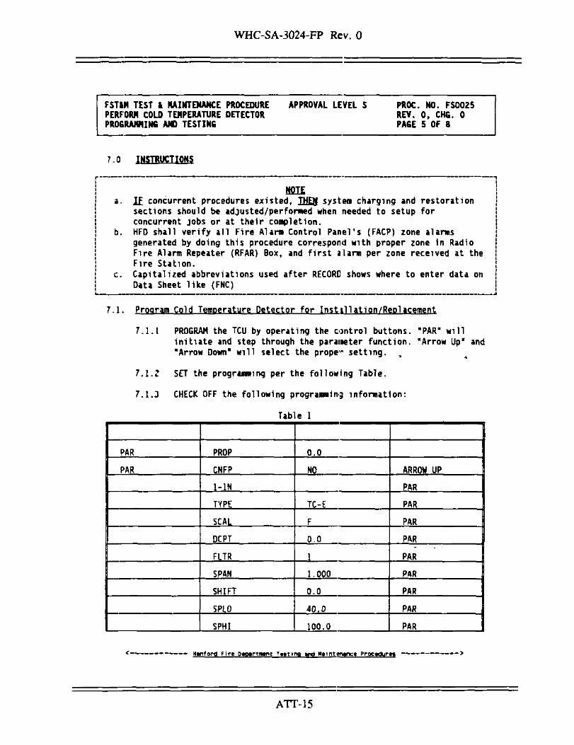
7.0 INSTRUCTIONS
NOTEa- If concurrent procedures existed, THEN system charging and restoration
sections should be adjusted/performed when needed to setup forconcurrent jobs or at their completion.
b. HFD shall verify all Fire Alarm Control Panel's (FACP) zone alarmsgenerated by doing this procedure correspond with proper zone in RadioFire Alarm Repeater (RFAR) Box, and first alarm per zone received at theFire Station.
c. Capitalized abbreviations used after RECORC shows where to enter data onData Sheet like (FNC)
7.1. Program Cold Temperature Detector for Instillation/Replacement
7.1.[ PROGRAM the TCU by operating the control buttons. "PAR" willinitiate and step through the parameter function. "Arrow Up" and"Arrow Down" will select the proper setting. ,
7.1.2 SET the programming per the following Table.
7.1.3 CHECK OFF the following programming information:
Table 1
PAR
PAR
PROP
CNFP
1-1N
TYPE
SCAL
DCPT
FLTR
SPAN
SHIFT
SPIQ
SPHI
0.0
NO
TC-E
F
0,0
1
1.000
0.0
40.0
100.0
ARROW UP
PAR
PAR
PAR
PAR
PAR
PAR
PAR
PAR
PAR
H*nford Fire Dwrtiwm Twting >nd WinMwnct Procadurtt
ATT-15

WHC-SA-3024-FP Rev. 0
FSTUt TEST & NAINTENANCE PROCEDUREPERFORM COLD TEMPERATURE DETECTORPROGRAMMING AND TESTING
APPROVAL LEVEL S PROC. NO. FSOO25REV. 0, CHG. 0PAGE 6 OF 8
SPRP
CNFP
1-1N
2-OP
CYCLE
OPAC
OPLO
OPHI
OPFL
CHYS
TCOO
CNFP
run
0.0
0
DRCT
100
0
0
.1
0
PAR
ARROW UP
ARROW UP
PAR
PAR
PAR
PAR
PAR
PAR
PAR
PAR
PAR
7.2 Testing
7.2.1 PRESS the "Arrow Up" button until the setpomt temperatureexceeds the control temperature by .2 to .5 degrees.
7.2.2 VERIFY receipt of trouble signal.
7.2.3 RESTORE the setpoint temperature to 40 degrees F. by pressing"Arrow Down".
7.2.4 RECORD results on the Data Sheet.
7.2.5 VERIFY trouble signal clears on FACP.
7-2.6 RESET FACP and verify normal supervisory service condition.
* — - . — - — Hanford ftrt Dtormtnt Ttiting and Hminttnanet' Proctdur—
ATT-16

WHC-SA-3024-FP Rev 0
FSTU TEST & MAINTENANCE PROCEDURE APPROVAL LEVEL S PROC. NO. FSOO25PERFORM COLD TEMPERATURE DETECTOR REV. 0, CHG. 0PROGRAMMING AND TESTING PAGE 7 OF 8
8.0 RESTORATION
8.1 Restore system to normal.
8.2 Reset and restore building iiam bell switch and all applicable fans,dampers, Interlocks and accessory function:, to normal position; recordrestoration of equipment on Data Sheet under PREREQUISITES FUNCTIONS(RESTORED).
8.3 If RFAR box has Bell Card Module, reset and restore bell silence switchto normal position,
8.4 Verify no abnormal conditions exist inside RFAR box; shut and lock RFARbox.
8.5 Ensure no alarm or trouble LED's are lit on FACP,
8.6 Notify building personnel that HFD and Maintenance have completedtesting and have returned alarm system to normal operation.
8.7 Notify HFD dispatcher testing has been completed and request all zonesbe restored, identify building and RFAR box number.
8.8 Request HFD dispatcher to bypass front button alarm on RFAR box.
8.9 After acknowledgement, press front button on RFAR box and verify threerounds of fire front button are received at fire stations. Initial DataSheet (RESTORATIONS 1).
8.10 Notify HFD dispatcher RFAR box is restored and the test has beencompleted.
8.11 Remain at RFAR box until light goes out on front of RFAR and InitialData Sheet (RESTORATIONS 2).
9.0 TESTING AND ACCEPTANCE
None.
< - - — — Hanford Firt Daoartwnt Ttitfnq »nd Mimtifrnce
ATT-17

WHC-SA-3024-FP Rev. 0
FST&H TEST k MAINTENANCE PROCEDURE APPROVAL LEVEL S PROC. NO. FSOO25PERFORM COLD TEMPERATURE DETECTOR REV. 0, CHG. 0PROGRAMMING AND TESTING PAGE 8 OF 8
10.0 DISPOSITION
10 ] Advise Building Manager/Administrator of any system impairments orabnormal conditions, Initial Data Sheet (RISTORATIONS 3).
20.;' HFD personnel complete and return all Fire System Alarm Test Reportforms to Fire Station #2 for file,
10.3 Report deficiencies or cause of early failure to Supervision.
10-4 Return Data Sheet(s) to Supervision and inform Supervision preventivemaintenance is complete.
11.0 BIBLIOGRAPHY
11/11 WHC-CM-4-3, Industrial Safety Manual. Section TE, "Tools and Equipment*,Standard No. PP-7, "Personal Protective Equipment", and Standard 6-1,"Lock and Tag".
11.2 HSRCM-1, Hanford Site Radiological Control Manual. Chapter 2, Part 3,"Posting", and Chapter 3, Part Zt "Work Preparation."
11.3 WHC-CM-4-3, Vol. 1, Standard FS-2, "Fire Protection System Inspection.Testing, and Maintenance",
Hanford F i r » amomrtmtnx T—ti'na and
ATT-18

B O M B.ippl
Paoa ol
BILL OF MATERIAL u.. FREEZING TEMPERATURE DETECTION m * • H" 2G-95-550
09/01/95 "•'"'"' SM KORSLUND Priority
It BinNO
Quantity
Untt
EitlmatadCoH
Raq /Stor* No
Eip DaHvary D « *
AppmvalO«(tSnatot
QCApproval
Slock No
Etoraga Locatton
70 RED LION TEMPERATURE CONTROL UNIT (TCU) P/N
EATCU0000. 1B6.00
56 HOFFMAN ENCLOSURE, NEMA 4, 6X6X1245.00 NA
ea
70 TYPE "E* THERMOCOUPLE P/N AX1008B0813.00
EA
70 FUSE HOLDERS; In-line Breakaway; p/n 6F453;
EAwith Insulating Boot; p/n 6F454 20,00
70 RELAY MODULE FOR RED LION MODEL TCU; P/N
FAOMD00000 9,30
1000 THERMOCOUPLE EXTENSION CABLE, TYPE E; P/N
FTE2O-5-5O2 .27 NA
D M . Raqutrad 09/01/95
Q Mandatory ffl Da.lrad
DaHvary location
2721EA
OA Clauaaa
E14,E22,CO2
andor
BRANOM INSTRUMENTS PO BOX80307 SEATTLE, WA 98108
SpaclM Intirucikin*
EmargancT
Coda/Cnat Crxla
3C600/MFMPM
Malarial Coonltnator
Cognlianl Enfltnaar IK •ppMcmbM
Cognbant Managar IK ippttetbtel
Plannar
Data
Data
Data
Data
M S W
MS IN
MSIN
M5IN
Phona No
PhonaNo
Phana No
PhonaNo
Qu aBt» A««uranca MSIN Phana No
Malarial flabaiad To and Racaivad By BC 66CW 174 1 fO7/94l

BILL OF MATERIALContinuation Shaat
hamNo
7
8
Quantity
Unit
70
EA
70
EA
Malarial Oaacriptton
CONNECTOR, THERMOCOUPLE. MALE AND FEMALE MALE
P/N 900E; FEMALE P/N 9 0 I E ; TYPE E
CABLE CLAMP, P/N 921
Cttknat*dCoat
5.00
.85
Aaq /Stom No
Exp Dalivary DataSafatv•N I
4
4
•KB"1
natot
NA
NA
QCApproval
Wort Raquact No
B O M Suppl
Pao* ol
Ontorad
Racalvad
Slack No
Bt«aga Locatkin
BC6rJ(»174

TYPICAL HOOK-UP FOR EACH ZONE
Not* 1Tfor • ft tea* unabl* to sufjport H 0. operation,H C May be used. S«t detail 1.
Note 2;I t U peraltsable to connect AC power via a conveniencereceptable. Us* cord cop,This option Is to be used InInstances where It Is not cose effective to run powerwiring back I D the FACP.
115 VAC(MAIN POWER) FROM PACP
O
FUSE 5 AMP
TO FACP SUPERVISORY ZONE
EOL TUD D¥ FACP MANUFACTURE!*
detail 1.
See Note 2
1234567B
910111213U1516
AL2/DP2-A
ALZ/OPZ-B
AL2 /0PZ-C
0P1-A
0P1-B
OP1-C
PGMDIS.
COMM
N/C
AL1-A
AL1-B
AL1-C
NOT USED
CONNECTION IS N\O.NORMAL SUPERVISORY CONDITIONSHELF CONDITION IS N.C.
_J See Note 1.
THERMOCOUPLE INPUTTYPE " E "
NOT USED
Oo
H»ntoKtoH
Related Documents