APPLICATION NOTE R01AN1665ES0101 Rev.1.01 Page 1 of 39 March 06, 2015 RL78 Family Digital Signal Controller Library - Filter Introduction This document presents the specifications for a Digital Signal Controller Library (DSCL) function library for the Renesas RL78 which includes generic specifications, detailed specifications for filter algorithm kernels and guidelines for the DSCL Library API. In this document, the word kernel refers to a common DSCL function such as FIR filter. In the DSCL library, several different C-language function calls may be associated with a single DSP kernel. To avoid confusion, the word kernel refers to the DSP algorithm, including the collection of functions that implement the DSP algorithm in the DSCL Library. Specific DSCL Library function names are used to refer to individual functions. The specification of this application is similar to RX DSP library V1.0, thus newer versions of RX DSP Library may have different specifications. Target Device RL78 core S3 - Unspecified Contents R01AN1665ES0101 Rev.1.01 March 06, 2015

Welcome message from author
This document is posted to help you gain knowledge. Please leave a comment to let me know what you think about it! Share it to your friends and learn new things together.
Transcript
APPLICATION NOTE
R01AN1665ES0101 Rev.1.01 Page 1 of 39
March 06, 2015
RL78 Family
Digital Signal Controller Library - Filter
Introduction
This document presents the specifications for a Digital Signal Controller Library (DSCL) function library for the
Renesas RL78 which includes generic specifications, detailed specifications for filter algorithm kernels and guidelines
for the DSCL Library API. In this document, the word kernel refers to a common DSCL function such as FIR filter. In
the DSCL library, several different C-language function calls may be associated with a single DSP kernel. To avoid
confusion, the word kernel refers to the DSP algorithm, including the collection of functions that implement the DSP
algorithm in the DSCL Library. Specific DSCL Library function names are used to refer to individual functions. The
specification of this application is similar to RX DSP library V1.0, thus newer versions of RX DSP Library may have
different specifications.
Target Device
RL78 core S3 - Unspecified
Contents
R01AN1665ES0101 Rev.1.01
March 06, 2015

RL78 Family Digital Signal Controller Library - Filter
R01AN1665ES0101 Rev.1.01 Page 2 of 39
March 06, 2015
1. DSCL Library Kernels........................................................................................................................ 3
1.1 List of Abbreviations and Acronyms .................................................................................................. 3
1.2 DSCL Library Build information ......................................................................................................... 3
1.2.1 Tool Chain Information ............................................................................................................. 3
2. DSCL Library API .............................................................................................................................. 4
2.1 Terminology ....................................................................................................................................... 4
2.2 Data structures .................................................................................................................................. 4
2.2.1 Vectors ..................................................................................................................................... 4
2.2.2 Algorithm kernel handles .......................................................................................................... 5
2.3 Function arguments........................................................................................................................... 6
2.4 Error handling .................................................................................................................................... 6
2.5 Rounding Support ............................................................................................................................. 7
3. Filter Function API ............................................................................................................................. 8
3.1 FIR Data Structure Definition ............................................................................................................ 8
3.2 FIR Initialize API ................................................................................................................................ 9
3.3 FIR Filter API ................................................................................................................................... 10
3.4 IIR Biquad Data Structure Definition ............................................................................................... 14
3.5 IIR Biquad State Size API ............................................................................................................... 15
3.6 IIR Biquad Initialize API ................................................................................................................... 16
3.7 IIR Biquad Filter API ........................................................................................................................ 17
3.8 Single Pole IIR Data Structure Definition ........................................................................................ 21
3.9 Single-Pole IIR Filter API ................................................................................................................ 22
4. Sample Workspace on CubeSuite+ ................................................................................................ 26
4.1 16-bit Fixed-point library only .......................................................................................................... 26
4.2 Resource Requirements ................................................................................................................. 29
4.2.1 Code Size and Stack Size ...................................................................................................... 29
4.2.2 Cycles and Accuracy .............................................................................................................. 30
5. Sample Workspace on IAR Embedded Workbench ....................................................................... 31
5.1 16-bit Fixed-point library only .......................................................................................................... 31
5.2 Resource Requirements ................................................................................................................. 34
5.2.1 Code Size and Stack Size ...................................................................................................... 34
5.2.2 Cycles and Accuracy .............................................................................................................. 35
General Precautions in the Handling of MPU/MCU Products ................................................................... 2

RL78 Family Digital Signal Controller Library - Filter
R01AN1665ES0101 Rev.1.01 Page 3 of 39
March 06, 2015
1. DSCL Library Kernels
Filter kernels defined in this document include:
1. Generic FIR
2. IIR Biquad
3. Single-pole IIR
1.1 List of Abbreviations and Acronyms
Abbreviation Full Form
DSC Digital Signal Controller
DSP Digital Signal Processor
FIR Finite Impulse Response
GPIO General Purpose I/O
I/O Input/Output
LSB Least Significant Bit
MSB Most Significant Bit
1.2 DSCL Library Build information
1.2.1 Tool Chain Information
The DSCL Library was built and tested using the following:
CubeSuite+ Version 1.02.00; Build tool: CA78K0R (V1.40)
IAR Embedded Workbench for Renesas RL78 Version 1.40.1; Build tool: IAR Compiler (V1.40.1.x)

RL78 Family Digital Signal Controller Library - Filter
R01AN1665ES0101 Rev.1.01 Page 4 of 39
March 06, 2015
2. DSCL Library API
In this document we outline aspects of the Renesas DSCL Library API design that are common to all functions within
the DSCL Library.
2.1 Terminology
In this document we use the word “kernel” to refer to a DSP algorithm (or a variant of a DSP algorithm) implemented
in the DSCL library. We use the word “function” to refer to a single, specific function call in the DSCL library API.
Note that a kernel’s implementation may require multiple functions. For example, a filter kernel typically requires one
or more functions for initialization and/or other housekeeping tasks, and a main function for the filter processing.
2.2 Data structures
The library will define the following categories of data structures:
Vectors
Algorithm kernel handles
2.2.1 Vectors
Vector data structures contain vector dimensions, and a pointer to the actual array of data:
typedef struct
{
uint32_t n;
void *data;
} vector_t;
Note: the user is responsible for allocating buffer memory for the vector data. In addition, because the “data” member
of the vector structure is declared as (void *), there is no need for separate vector structures for the different data types
supported by the library.

RL78 Family Digital Signal Controller Library - Filter
R01AN1665ES0101 Rev.1.01 Page 5 of 39
March 06, 2015
2.2.2 Algorithm kernel handles
For kernel functions that require state information, constant data, and/or various run-time parameters, all such data is
aggregated in a “handle” data structure specific to the kernel function (or class of functions, e.g. transforms). For
example, an FIR filter handle may be defined as follows:
typdef struct
{
uint16_t taps; // number of filter taps
void *coefs; // pointer to filter coefficients
void *state; // pointer to filter state data, including
// the filter’s delay line and any other
// implementation-dependent state
uint16_t options; // option flags that may specify rounding,
// saturation, or other behaviors
} r_dscl_firfilter_t;
Note: the handle data structure contains only members that need to be visible to the user. Some kernels may need to
maintain additional implementation-specific states.
All members of kernel “handle” data structures must be initialized by the user. This includes pointers to coefficient
and/or state memory. Coefficient and/or state memory must be allocated by the user. Some DSP kernels have
implementation-dependent memory requirements for the state and/or coefficients. In such cases, API functions are
provided that return the amount of memory to be allocated, given the desired parameters for the kernel.
Also note that many functions will have to perform run-time checks on handle structure members such as ‘options,’ in
order to branch to the appropriate implementation of the kernel for the given parameters. To ensure that the most
common implementation selections accrue the smallest overhead from these run-time checks, a default value of NULL
is defined wherever possible. The default value provides the most common desired behavior (often the fastest possible
implementation of the kernel).
Kernel parameters supplied in a handle structure must not be changed by the user without re-initializing the kernel. For
example, changing the rounding mode or number of taps of an FIR filter “on the fly” is prohibited. When changing
such kernel parameters, users must ensure that sufficient memory is allocated for the kernel’s internal state, given the
new parameters, and must re-initialize the kernel. Note that this restriction does not apply to changes to filter
coefficient values. Filter coefficients can be always changed “on the fly.”

RL78 Family Digital Signal Controller Library - Filter
R01AN1665ES0101 Rev.1.01 Page 6 of 39
March 06, 2015
2.3 Function arguments
All functions accept arguments in the following order:
<handle>: a pointer to a kernel handle data structure containing kernel-specific state, coefficients, parameters,
and options.
<input1>…<inputN>: one or more input arguments passed as pointers for most data types, except scalar data.
Scalar data values may be passed directly.
<output1>…<outputN>: one or more output pointers
<additional options>: any kernel parameters or options that are not included in the kernel handle data structure.
Note: a function call may not include all of the above elements. For example a FIR filter initialization function does not
have inputs or outputs.
Most functions return a 16-bit integer result. The integer result may contain an error code or other information required
for application housekeeping tasks. For example, the return value may indicate the amount of memory that the user
must allocate for a kernel’s internal state, or may indicate the occurrence of kernel-specific special conditions.
Exceptions to this rule occur where functions compute a single real-valued scalar result, and no error conditions can
occur. In such cases, the result may be returned by the function instead of a status code.
Functions whose return value indicates the amount of memory that the user must allocate for some task may also return
a negative value to indicate an error condition (see section 2.4 Error handling). Since C99, the malloc() function expects
size_t, which is an unsigned data type. The actual bit-width of size_t is platform dependent. Therefore, care must be
taken to ensure that a valid (non-error) result has been returned by the DSCL Library function before passing the result
to malloc().
In summary, most function calls have the following format:
int16_t <status/size> = function(<handle>, <input1>,…, <inputN>, <output1>,…,
<outputN>, <additional options>);
Where most functions will include only a subset of the above argument classes.
2.4 Error handling
All functions perform checks on input arguments and kernel parameters to the greatest extent possible. Most functions
return a 16-bit integer status code. Functions that return the size of a kernel’s internal state (for memory allocation
purposes) are a noteworthy exception. For example, the R_DSCL_FIR_stateSize_i16i16 functions fall in this latter
category.
All functions return a negative integer value to indicate an error condition. Specific error conditions are assigned
unique negative integer values specified on a per-function basis. Functions may return zero for success, or may return a
positive integer value to indicate non-error result or special condition. For example, the
R_DSCL_FIR_stateSize_i16i16 functions return the memory size requirement for the FIR filter’s state. Other functions
may return positive integer values indicating special non-error conditions such as the occurrence of overflow.
Functions that return a memory size result for memory allocation purposes may return zero if no memory is required for
the given kernel parameters.
Note the distinction between error and status conditions: error conditions (declared with
R_DSCL_ERR_<description>) always have a negative integer value and indicate conditions that prevent operation of a
kernel, e.g. a NULL input pointer. In contrast, status conditions (declared with R_DSCL_STATUS_<description>)
have positive integer values (or zero for R_DSCL_STATUS_OK) and indicate conditions that may impact the kernel’s
output, but do not prevent the arithmetic operations of the kernel from proceeding. For example, arithmetic overflow is
indicated with a status condition. Thus, status conditions can be ignored in some applications, while error conditions
always require attention. The assignment of negative values to error codes and positive (or zero) values to status codes
allows the user’s code to easily distinguish between these two types of conditions.
Error and status codes will be defined by an enum declaration in the header file r_dscl_types.h.
The following common formats will be used for error codes of all functions:
R_DSCL_STATUS_OK: No issues encountered. This code has a value of zero.
R_DSCL_ERR_<pointer>_NULL: A null pointer was encountered by the function. <pointer> names the
offending pointer, e.g. R_DSCL_ERR_INPUT_NULL means that the pointer to an input argument is null. If
input is a vector or matrix, this code would also be used if the data pointer within the vector/matrix struct is null.
RL78 Family Digital Signal Controller Library - Filter
R01AN1665ES0101 Rev.1.01 Page 7 of 39
March 06, 2015
R_DSCL_ERR_INVALID_<x>: an option or parameter passed to the function (via a handle or directly) is not
supported by the implementation. <x> identifies the offending function argument, kernel parameter, or struct
member. For example, if a filter’s handle structure has an ‘options’ member that specified rounding modes, and
this member has an unsupported value, then the R_DSCL_ERR_INVALID_OPTIONS code would be used.
In addition, some function-specific error and status codes are defined. The error and status codes defined in Phase 1 of
the DSCL library specification include:
R_DSCL_STATUS_OK = Status Ok, no issues encountered.
R_DSCL_ERR_HANDLE_NULL = If the pointer to the handle is NULL.
R_DSCL_ERR_INPUT_NULL = If the pointer to the input vector or the data therein is NULL.
R_DSCL_ERR_OUTPUT_NULL = If the pointer to the output vector or the data therein is NULL.
R_DSCL_ERR_STATE_NULL = If the pointer to the FIR or IIR filter internal state is NULL.
R_DSCL_ERR_COEFF_NULL = If the pointer to the coefficient array is NULL.
R_DSCL_ERR_INVALID_TAPS = The number of filter taps is zero or is not supported by the implementation.
R_DSCL_ERR_INVALID_STAGES = The number of filter stages is zero or is not supported by the
implementation.
R_DSCL_ERR_INVALID_OPTIONS = options value in handle specified a mode not currently supported.
2.5 Rounding Support
Some kernels in the DSCL Library provide support for multiple rounding mode. These modes apply to the fixed-
point data types.
Rounding modes are supported via an options element in the kernel’s handle structure. The following bit-fields
in options are reserved for rounding and saturation modes:
Bits 0-2: rounding mode
R_DSCL_ROUNDING_DEFAULT = 0
R_DSCL_ROUNDING_TRUNC = 1
R_DSCL_ROUNDING_NEAREST = 2
reserved = 3-7
Note: R_DSCL_ROUNDING_DEFAULT is the default behaviors of the kernals. For all the filter types in the
library, the default behavior is the truncation.
RL78 Family Digital Signal Controller Library - Filter
R01AN1665ES0101 Rev.1.01 Page 8 of 39
March 06, 2015
3. Filter Function API
This section covers the filter functions implemented in the RL78 DSCL Library.
3.1 FIR Data Structure Definition
The FIR kernel uses a handle to the filter of type r_dscl_firfilter_t. This handle is passed as part of the call to the filter.
The data structure for the handle type is as follows:
typedef struct
{
uint16_t taps; // number of filter taps
void * coefs; // pointer to filter coefficients
void * state; // pointer to filter state data, including the filter’s
delay line
// and any other implementation-dependent state
uint16_t options;// options that specify rounding, saturation, or other
behaviors
} r_dscl_firfilter_t;
Each member of the data structure is explained below:
taps = Number of filter taps
coefs = Pointer to the coefficient vector (must be the same data type as the input vector). The content of this array
is maintained by the user.
state = Pointer to the internal state of the filter, including the delay line and any other implementation-dependent
state. The memory for the internal state is allocated by the user and the content of the internal state is maintained by
the kernel.
options = A bit-mapped parameter controlling options. See “Rounding Support” in software overview section, for
the definition of available modes.

RL78 Family Digital Signal Controller Library - Filter
R01AN1665ES0101 Rev.1.01 Page 9 of 39
March 06, 2015
3.2 FIR Initialize API
This is a function used to initialize the filter state (including zeroing the delay line and other parameters), given the
options specified in the handle. It must be called once prior to invoking the run-time calling function.
Format
int16_t R_DSCL_FIR_Init_i16i16 (r_dscl_firfilter_t * handle)
Parameters
handle Pointer to an instance of the r_dscl_firfilter_t data structure.
handle →state Pointer to the starting address of delay line, which shall be on the same array as the input data.
Return Values
R_DSCL_STATUS_OK = Status OK, no issues encountered.
R_DSCL_ERR_HANDLE_NULL = Pointers to the handle is NULL.
R_DSCL_ERR_STATE_NULL = Pointer to delay-line, is NULL.
R_DSCL_ERR_INVALID_TAPS = Number of taps is 0.
R_DSCL_ERR_INVALID_OPTIONS = options value in handle specified a mode not currently supported.
Others = Reserved.
NOTE: This function initializes only the contents of the FIR state pointed to by the state element of the handle structure.
It does not initialize the filter coefficients or any other contents of the handle structure, which must be initialized
separately.
Example
Since this function is not used by itself, see FIR filter example for the use of this in Context.
Restrictions
Handle must have already been instantiated. See FIR example for more details.

RL78 Family Digital Signal Controller Library - Filter
R01AN1665ES0101 Rev.1.01 Page 10 of 39
March 06, 2015
3.3 FIR Filter API
The block finite impulse response (FIR) filter kernel operates on a user selectable number of input samples and
produces the same number of output samples each time it is invoked.
Format
int16_t R_DSCL_FIR_i16i16 (const r_dscl_firfilter_t * handle, const vector_t *
input, vector_t * output)
Parameters
handle Pointer to an instance of the r_dscl_firfilter_t data structure.
input Pointer to an instance of vector_t data structure for the input data. Neither the instance nor the actual
input data will be altered by the function.
input→n Number of input samples to be processed by the function. This value must be set before the function call.
input→data Pointer to starting address of the input data. This pointer must be set before the function call.
output Pointer to an instance of vector_t data structure for the output data. Both the instance and the actual
output data will be altered by the function.
output→n Number of output samples produced by the function. This value will be filled by the function.
output→data Pointer to the output data buffer. This pointer must be set before the function call. The output data
buffer will be filled by the function.
Return Values
R_DSCL_STATUS_OK = Status OK, no issues encountered.
R_DSCL_ERR_HANDLE_NULL = If the pointer to the handle is NULL.
R_DSCL_ERR_INPUT_NULL = If the pointer to the input vector or the data therein is NULL.
R_DSCL_ERR_OUTPUT_NULL = If the pointer to the output vector or the data therein is NULL.
R_DSCL_ERR_STATE_NULL = If the pointer to the filter internal state is NULL.
R_DSCL_ERR_COEFF_NULL = If the pointer to the coefficient array is NULL.
R_DSCL_ERR_INVALID_TAPS = The number of filter taps is zero.
R_DSCL_ERR_INVALID_OPTIONS = options value in handle specified a mode not currently supported.
Others = Reserved.
Description
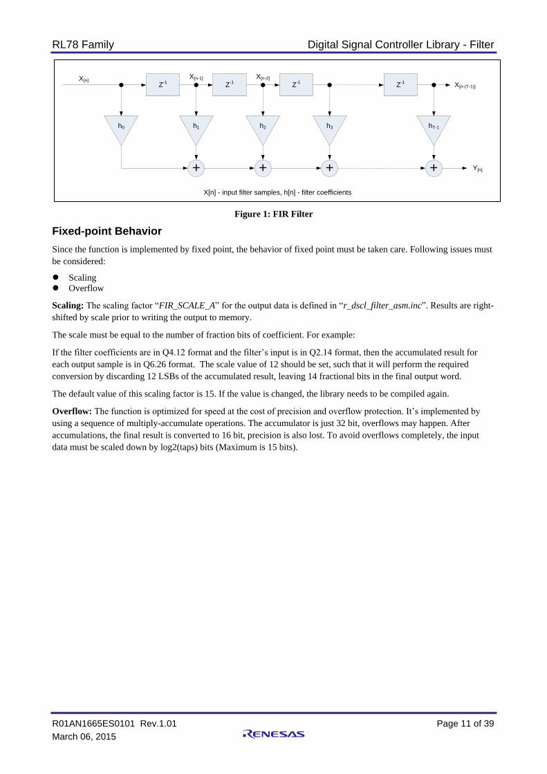
The Block FIR filter kernels implement a finite impulse response filter on each input sample. The following equation
shows the general structure of a T-tap FIR filter where h represents the coefficients, x represents the input data, and y
represents the output data.
𝑦(𝑛) = ∑ ℎ(𝑖) ∗ 𝑥(𝑛 − 𝑖)
𝑇−1
𝑖=0
Each output sample is the result of performing FIR filter of n taps. This is shown graphically in Figure 1.
RL78 Family Digital Signal Controller Library - Filter
R01AN1665ES0101 Rev.1.01 Page 11 of 39
March 06, 2015
Figure 1: FIR Filter
Fixed-point Behavior
Since the function is implemented by fixed point, the behavior of fixed point must be taken care. Following issues must
be considered:
Scaling
Overflow
Scaling: The scaling factor “FIR_SCALE_A” for the output data is defined in “r_dscl_filter_asm.inc”. Results are right-
shifted by scale prior to writing the output to memory.
The scale must be equal to the number of fraction bits of coefficient. For example:
If the filter coefficients are in Q4.12 format and the filter’s input is in Q2.14 format, then the accumulated result for
each output sample is in Q6.26 format. The scale value of 12 should be set, such that it will perform the required
conversion by discarding 12 LSBs of the accumulated result, leaving 14 fractional bits in the final output word.
The default value of this scaling factor is 15. If the value is changed, the library needs to be compiled again.
Overflow: The function is optimized for speed at the cost of precision and overflow protection. It’s implemented by
using a sequence of multiply-accumulate operations. The accumulator is just 32 bit, overflows may happen. After
accumulations, the final result is converted to 16 bit, precision is also lost. To avoid overflows completely, the input
data must be scaled down by log2(taps) bits (Maximum is 15 bits).
X[n]Z
-1
h0
+
h1
Z-1
+
h2
Z-1
+
h3
Z-1
+
hT-1
X[n-(T-1)]
X[n-1] X[n-2]
X[n] - input filter samples, h[n] - filter coefficients
Y[n]
RL78 Family Digital Signal Controller Library - Filter
R01AN1665ES0101 Rev.1.01 Page 12 of 39
March 06, 2015
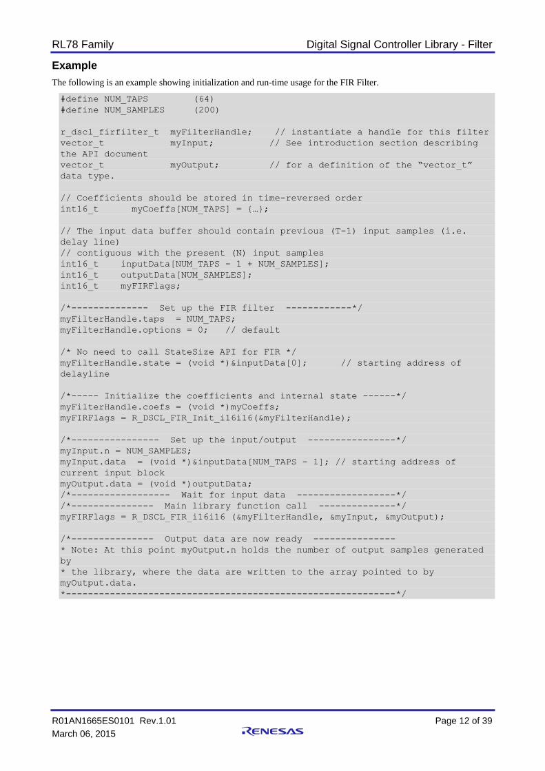
Example
The following is an example showing initialization and run-time usage for the FIR Filter.
#define NUM_TAPS (64)
#define NUM_SAMPLES (200)
r_dscl_firfilter_t myFilterHandle; // instantiate a handle for this filter
vector_t myInput; // See introduction section describing
the API document
vector_t myOutput; // for a definition of the “vector_t”
data type.
// Coefficients should be stored in time-reversed order
int16_t myCoeffs[NUM_TAPS] = {…};
// The input data buffer should contain previous (T-1) input samples (i.e.
delay line)
// contiguous with the present (N) input samples
int16_t inputData[NUM_TAPS - 1 + NUM_SAMPLES];
int16_t outputData[NUM_SAMPLES];
int16_t myFIRFlags;
/*-------------- Set up the FIR filter ------------*/
myFilterHandle.taps = NUM_TAPS;
myFilterHandle.options = 0; // default
/* No need to call StateSize API for FIR */
myFilterHandle.state = (void *)&inputData[0]; // starting address of
delayline
/*----- Initialize the coefficients and internal state ------*/
myFilterHandle.coefs = (void *)myCoeffs;
myFIRFlags = R_DSCL_FIR_Init_i16i16(&myFilterHandle);
/*---------------- Set up the input/output ----------------*/
myInput.n = NUM_SAMPLES;
myInput.data = (void *)&inputData[NUM_TAPS - 1]; // starting address of
current input block
myOutput.data = (void *)outputData;
/*------------------ Wait for input data ------------------*/
/*--------------- Main library function call --------------*/
myFIRFlags = R_DSCL_FIR_i16i16 (&myFilterHandle, &myInput, &myOutput);
/*--------------- Output data are now ready ---------------
* Note: At this point myOutput.n holds the number of output samples generated
by
* the library, where the data are written to the array pointed to by
myOutput.data.
*------------------------------------------------------------*/
RL78 Family Digital Signal Controller Library - Filter
R01AN1665ES0101 Rev.1.01 Page 13 of 39
March 06, 2015
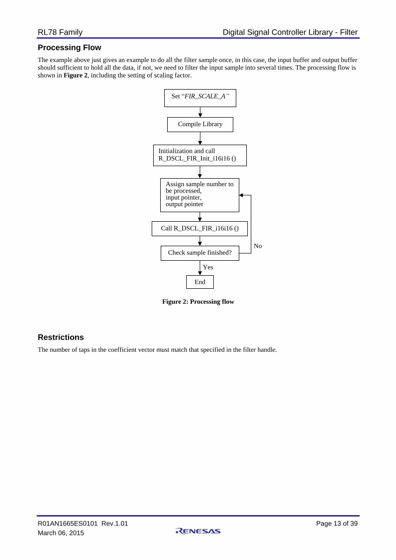
Processing Flow
The example above just gives an example to do all the filter sample once, in this case, the input buffer and output buffer
should sufficient to hold all the data, if not, we need to filter the input sample into several times. The processing flow is
shown in Figure 2, including the setting of scaling factor.
Figure 2: Processing flow
Restrictions
The number of taps in the coefficient vector must match that specified in the filter handle.
Set “FIR_SCALE_A”
Compile Library
Initialization and call R_DSCL_FIR_Init_i16i16 ()
Assign sample number to be processed, input pointer, output pointer
Call R_DSCL_FIR_i16i16 ()
Check sample finished?
End
No
Yes

RL78 Family Digital Signal Controller Library - Filter
R01AN1665ES0101 Rev.1.01 Page 14 of 39
March 06, 2015
3.4 IIR Biquad Data Structure Definition
The following is the definition of the filter handle r_dscl_iirbiquad_t.
typedef struct
{
uint16_t stages; // number of biquad stages
void * coefs; // pointer to filter coefficients
void * state; // pointer to filter’s internal state (delay line)
uint16_t options; // options that specify rounding, saturation, or other behaviors
} r_dscl_iirbiquad_t;
Each member of the data structure is explained below:
stages = Number of biquad stages
coefs = Pointer to the coefficient vector (must be the same data type as the input vector). The content of this array
is maintained by the user.
state = Pointer to the internal state of the filter, including the delay line and any other implementation-dependent
state. The memory for the internal state is allocated by the user and the content of the internal state is maintained by
the kernel.
options = A bit-mapped parameter controlling options. See “Rounding Support” section, for the definition of
available modes.
RL78 Family Digital Signal Controller Library - Filter
R01AN1665ES0101 Rev.1.01 Page 15 of 39
March 06, 2015
3.5 IIR Biquad State Size API
This is a “maintenance” function for the IIR filters. This function returns the size (in bytes) that must be allocated by
the user to maintain the internal state (including the delay line) of the filter.
Format
int16_t R_DSCL_IIRBiquad_StateSize_i16i16 (const r_dscl_iirbiquad_t * handle)
Parameters
handle Pointer to an instance of the r_dscl_iirbiquad_t data structure.
Return Values
Buffer Size in Bytes (type int16_t) required by the filter.
Note: The size returned should allow the implementer to use this buffer to maintain any private information associated
with the filter including items such as pointers, a record of input and output data types, etc. Also the size returned by
this function does not include the filter handle, nor does it include the coefficient array.
Description
The function can be used as part of the filter initialization to decide the buffer size a user must allocate. Alternatively,
the user can use this function to determine the required memory size during development, and allocate a static array of
that size for the internal state (for example, in the faster on-chip RAM).
Note: Since C99, the malloc() function expects size_t, which is an unsigned data type. The actual bit-width of size_t is
platform dependent. If malloc(R_DSCL_IIRBiquad_StateSize_i16i16()) is used to allocate the memory for the internal
state, and R_DSCL_IIRBiquad_StateSize_i16i16() returns a negative value, unexpected behavior could happen.
Example
Since this function is not used by itself, see IIR filter example for the use of this in Context.
Restrictions
IIRHandle must have already been instantiated. See IIR example for more details.
RL78 Family Digital Signal Controller Library - Filter
R01AN1665ES0101 Rev.1.01 Page 16 of 39
March 06, 2015
3.6 IIR Biquad Initialize API
This is a function used to initialize the filter state (including zeroing the delay line and other parameters), given the
options specified in the handle. It must be called once prior to invoking the run-time calling function.
Format
int16_t R_DSCL_IIRBiquad_Init_i16i16 (r_dscl_iirbiquad_t * handle)
Parameters
handle Pointer to an instance of the r_dscl_iirbiquad_t data structure.
Return Values
R_DSCL_STATUS_OK = Status OK, no issues encountered.
R_DSCL_ERR_HANDLE_NULL = Pointers to the handle is NULL.
R_DSCL_ERR_STATE_NULL = Pointer to delay-line, is NULL.
R_DSCL_ERR_INVALID_STAGES= Number of biquad stages is 0.
R_DSCL_ERR_INVALID_OPTIONS = options value in handle specified a mode not currently supported.
Others = Reserved.
NOTE: This function initializes only the contents of the IIR state pointed to by the state element of the handle structure.
It does not initialize the filter coefficients or any other contents of the handle structure, which must be initialized
separately.
Description
This is a function used to initialize the filter state (including zeroing the delay line and possibly other implementation-
dependent parameters). It must be called once prior to invoking the run-time calling function.
Example
Since this function is not used by itself, see IIR filter example for the use of this in Context.
Restrictions
IIRHandle must have already been instantiated. See IIR example for more details.
RL78 Family Digital Signal Controller Library - Filter
R01AN1665ES0101 Rev.1.01 Page 17 of 39
March 06, 2015
3.7 IIR Biquad Filter API
This kernel implements the IIR (Infinite Impulse Response) filter in the form of cascaded biquads. A biquad is a section
of the 2nd-order IIR filter. For higher order IIR filters, cascaded biquads often generate smaller numerical errors than a
direct-form implementation.
A biquad can have many forms, such as direct-forms I and II, transposed direct-forms I and II. Each has its advantages
and disadvantages. The IIR biquad API is designed by using direct-forms I.
This kernel operates on a user selectable number of input samples and produces the same number of output samples
each time it is invoked. The number of cascaded biquads is also selectable by the user.
FORMAT
int16_t R_DSCL_IIRBiquad_i16i16 (const r_dscl_iirbiquad_t * handle, const
vector_t * input, vector_t * output)
Parameters
handle Pointer to an instance of the r_dscl_iirbiquad_t data structure.
input Pointer to an instance of vector_t data structure for the input data. Neither the instance nor the actual
input data will be altered by the function.
input→n Number of input samples to be processed by the function. This value must be set before the function call.
input→data Pointer to the input data buffer. This pointer must be set before the function call.
output Pointer to an instance of vector_t data structure for the output data. Both the instance and the actual
output data will be altered by the function.
output→n Number of output samples produced by the function. This value will be filled by the function.
output→data Pointer to the output data buffer. This pointer must be set before the function call. The output data
buffer will be filled by the function.
Return Values
R_DSCL_STATUS_OK = Status OK, no issues encountered.
R_DSCL_ERR_HANDLE_NULL = If the pointer to the handle is NULL.
R_DSCL_ERR_INPUT_NULL = If the pointer to the input vector or the data therein is NULL.
R_DSCL_ERR_OUTPUT_NULL = If the pointer to the output vector or the data therein is NULL.
R_DSCL_ERR_STATE_NULL = If the pointer to the filter internal state is NULL.
R_DSCL_ERR_COEFF_NULL = If the pointer to the coefficient array is NULL.
R_DSCL_ERR_INVALID_STAGES= Number of biquad stages is 0.
R_DSCL_ERR_INVALID_OPTIONS = options value in handle specified a mode not currently supported.
Others = Reserved.
Description
The IIR biquad filter is in the form of cascaded biquads. Each biquad is a section of the 2nd-order IIR filter with the
following equation between its input and output:
𝑦(𝑛) = 𝑏0 ∗ 𝑥(𝑛) + 𝑏1 ∗ 𝑥(𝑛 − 1) + 𝑏2 ∗ 𝑥(𝑛 − 2) − 𝑎1 ∗ 𝑦(𝑛 − 1) − 𝑎2 ∗ 𝑦(𝑛 − 2)
where y(n) is the output sample, x(n) is the input sample, y(n-1) and x(n-1) are output and input samples delayed by one
sampling period, respectively, y(n-2) and x(n-2) are output and input samples delayed by two sampling periods,
respectively, b0, b1, and b2 are feed forward coefficients, and a1 and a2 are feedback coefficients.
The overall transfer function is as below:

RL78 Family Digital Signal Controller Library - Filter
R01AN1665ES0101 Rev.1.01 Page 18 of 39
March 06, 2015
𝐻(𝑧) = ∏𝑏0 + 𝑏1𝑧−1 + 𝑏2𝑧−2
1 + 𝑎1𝑧−1 + 𝑎2𝑧−2
𝑁−1
0
where N is the number of cascaded biquad stages. Note that each stage has a different set of coefficients b0, b1, b2, a1,
and a2.
Figure 3 shows the diagram of IIR biquad Direct Form I.
Figure 3: IIR Bi-Quad, Direct Form I
Fixed-point Behavior
Since the function is implemented by fixed point, the behavior of fixed point must be taken care. Following issues must
be considered:
Scaling
Overflow
Scaling: The scaling factor “IIR_BQ_SCALE_A” for the output data is defined in “r_dscl_filter_asm.inc”. Results are
right-shifted by scale prior to writing the output to memory.
The scale must be equal to the number of fraction bits of coefficient. For example:
If the filter coefficients are in Q4.12 format and the filter’s input is in Q2.14 format, then the accumulated result for
each output sample is in Q6.26 format. The scale value of 12 should be set, such that it will perform the required
conversion by discarding 12 LSBs of the accumulated result, leaving 14 fractional bits in the final output word.
The default value of this scaling factor is 14. This means the coefficients can represent the value in the range of [-2, 2).
If all the coefficients values are in the range of [-1, 1), the scaling factor can be changed to 15. To do this, the library
needs to be compiled again.
Overflow: The function is optimized for speed at the cost of precision and overflow protection. It’s implemented by
using a sequence of multiply-accumulate operations. The accumulator is just 32 bit, overflows may happen. After
accumulations, the final result is converted to 16 bit, precision is also lost. To avoid overflows completely, the input
data must be scaled down by 3 bits (Maximum is 15 bits).
Z-1
Z-1
+
X[n]b
k0 +
+
Yk[n]
Z-1
-ak2
Z-1
-ak1
Xk[n] – Input Samples, Y
k[n] Output Samples, b
k[n]/a
k[n] Filter Coefficients, Z
-1 – Delay Line
bk2
bk1
RL78 Family Digital Signal Controller Library - Filter
R01AN1665ES0101 Rev.1.01 Page 19 of 39
March 06, 2015
Example
The following is an example showing how to use IIR biquad function.
#define NUM_TAPS_PER_BIQUAD (5)
#define NUM_BIQUAD_STAGES (3)
r_dscl_iirbiquad_t myFilterHandle; // instantiate a handle for my use
vector_t myInput; // See introduction section API section
vector_t myOutput; // for a definition of the “vector_t”
data type
int16_t myCoeffs[NUM_TAPS_PER_BIQUAD * NUM_BIQUAD_STAGES]
= {b0, b1, b2, a1, a2,…};
int16_t myDLine[NUM_TAPS_PER_BIQUAD * NUM_BIQUAD_STAGES];
int16_t inputData[NUM_SAMPLES];
int16_t outputData[NUM_SAMPLES];
int16_t myIIRFlags;
int16_t dynMemSize, staMemSize;
/*-------------- Set up the IIR filter biquads ------------*/
myFilterHandle.stages = NUM_BIQUAD_STAGES;
/* Setup data format and options */
myFilterHandle.options = 0; // default
/* !!! It is important to setup the stages and the form before */
/* !!! calling function R_DSCL_IIRBiquad_StateSize_i16i16 () */
staMemSize = NUM_TAPS_PER_BIQUAD * NUM_BIQUAD_STAGES * sizeof(int16_t);
dynMemSize = R_DSCL_IIRBiquad_StateSize_i16i16(&myFilterHandle);
if (staMemSize >= dynMemSize)
{
myFilterHandle.state = (void *)myDLine; // probably more common
}
else
{
myFilterHandle.state = malloc((size_t) dynMemSize); //malloc expects size_t
}
/* Initialize the coefficients and internal state */
myFilterHandle.coefs = (void *)myCoeffs;
myIIRFlags = R_DSCL_IIRBiquad_Init_i16i16(&myFilterHandle);
/*---------------- Set up the input/output ----------------*/
myInput.n = NUM_SAMPLES;
myInput.data = (void *)inputData;
myOutput.data = (void *)outputData;
/*------------------ Wait for input data ------------------*/
/*--------------- Main library function call --------------*/
myIIRFlags = R_DSCL_IIRBiquad_i16i16(&myFilterHandle, &myInput, &myOutput);
/*--------------- Output data are now ready ---------------*/
/* Note: At this point myOutput.n holds the number of output samples generated
by
* the library, where the data are written to the array pointed to by
myOutput.data.
*------------------------------------------------------------*/
RL78 Family Digital Signal Controller Library - Filter
R01AN1665ES0101 Rev.1.01 Page 20 of 39
March 06, 2015
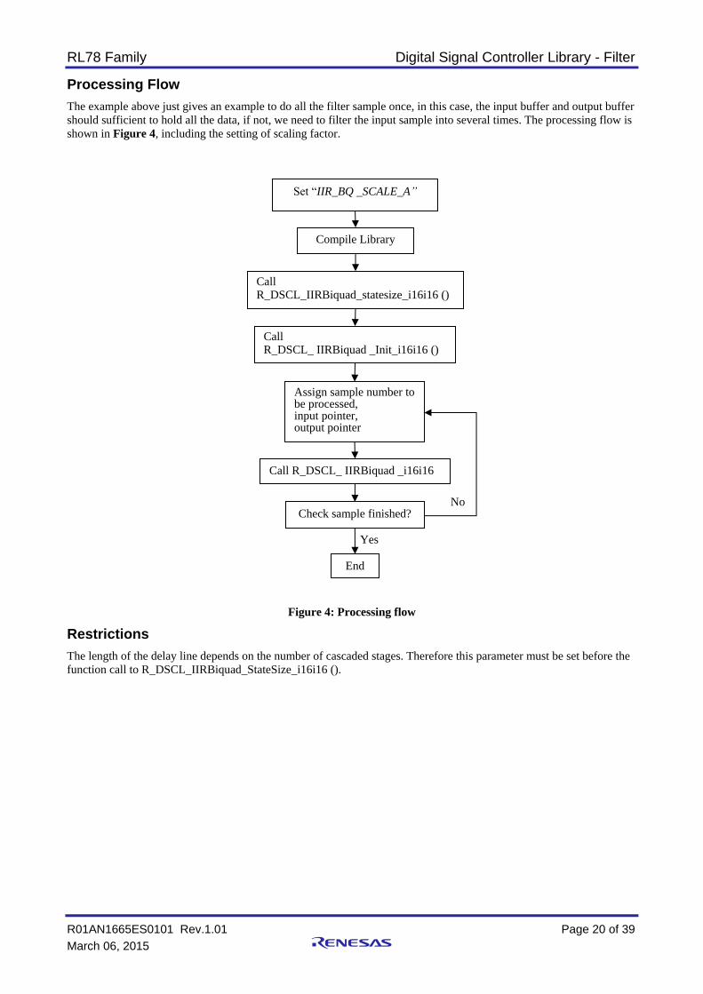
Processing Flow
The example above just gives an example to do all the filter sample once, in this case, the input buffer and output buffer
should sufficient to hold all the data, if not, we need to filter the input sample into several times. The processing flow is
shown in Figure 4, including the setting of scaling factor.
Figure 4: Processing flow
Restrictions
The length of the delay line depends on the number of cascaded stages. Therefore this parameter must be set before the
function call to R_DSCL_IIRBiquad_StateSize_i16i16 ().
Set “IIR_BQ _SCALE_A”
Compile Library
Call R_DSCL_ IIRBiquad _Init_i16i16 ()
Assign sample number to be processed, input pointer, output pointer
Call R_DSCL_ IIRBiquad _i16i16
()
Check sample finished?
End
No
Yes
Call R_DSCL_IIRBiquad_statesize_i16i16 ()
RL78 Family Digital Signal Controller Library - Filter
R01AN1665ES0101 Rev.1.01 Page 21 of 39
March 06, 2015
3.8 Single Pole IIR Data Structure Definition
The following is the definition of the filter handle r_dscl_iirsinglepole_t, which is used for all variants of the single-pole
filter kernel.
typdef struct
{
void * coefs; // pointer to filter coefficient
void * state; // pointer to filter’s internal state (delay
line)
uin16_t options; // options that specify rounding, saturation,
or other behaviors
} r_dscl_iirsinglepole_t;
Each member of the data structure is explained below:
coefs = Pointer to the coefficient of the feedback tap (must be the same data type as the input). The coefficient is
maintained by the user.
state = Pointer to the state of the feedback tap. The state is maintained by the kernel.
options = A bit-mapped parameter controlling options. See “Rounding Support” section, for the definition of
available modes.
RL78 Family Digital Signal Controller Library - Filter
R01AN1665ES0101 Rev.1.01 Page 22 of 39
March 06, 2015
3.9 Single-Pole IIR Filter API
This kernel implements the single-pole filter, which is an IIR (Infinite Impulse Response) filter with one feedback tap.
The maximum gain is unity.
Format
int16_t R_DSCL_IIRSinglePole_i16i16 ( const r_dscl_iirsinglepole_t * handle,
const vector_t * input, vector_t * output)
Parameters
handle Pointer to an instance of the r_dscl_iirsinglepole_t data structure.
input Pointer to an instance of vector_t data structure for the input data. Neither the instance nor the actual
input data will be altered by the function.
input→n Number of input samples to be processed by the function. This value must be set before the function call.
input→data Pointer to the input data buffer. This pointer must be set before the function call.
output Pointer to an instance of vector_t data structure for the output data. Both the instance and the actual
output data will be altered by the function.
output→n Number of output samples produced by the function. This value will be filled by the function.
output→data Pointer to the output data buffer. This pointer must be set before the function call. The output data
buffer will be filled by the function.
Return Values
R_DSCL_STATUS_OK = Status OK, no issues encountered.
R_DSCL_ERR_HANDLE_NULL = If the pointer to the handle is NULL.
R_DSCL_ERR_INPUT_NULL = If the pointer to the input vector or the data therein is NULL.
R_DSCL_ERR_OUTPUT_NULL = If the pointer to the output vector or the data therein is NULL.
R_DSCL_ERR_INVALID_OPTIONS = options value in handle specified a mode not currently supported.
Others = Reserved.
Note: this kernel does not provide an init function. It is the user’s responsibility to initialize the internal state to 0.
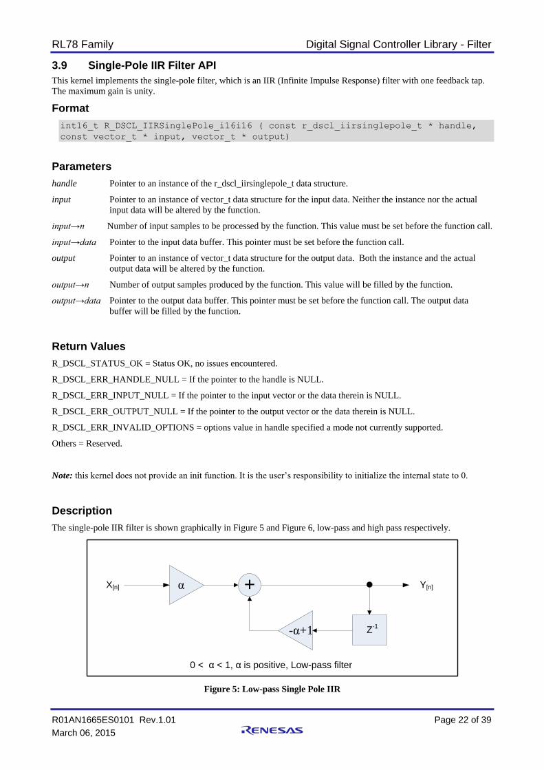
Description
The single-pole IIR filter is shown graphically in Figure 5 and Figure 6, low-pass and high pass respectively.
Figure 5: Low-pass Single Pole IIR
X[n] α + Y[n]
Z-1
-α+1
0 < α < 1, α is positive, Low-pass filter
RL78 Family Digital Signal Controller Library - Filter
R01AN1665ES0101 Rev.1.01 Page 23 of 39
March 06, 2015
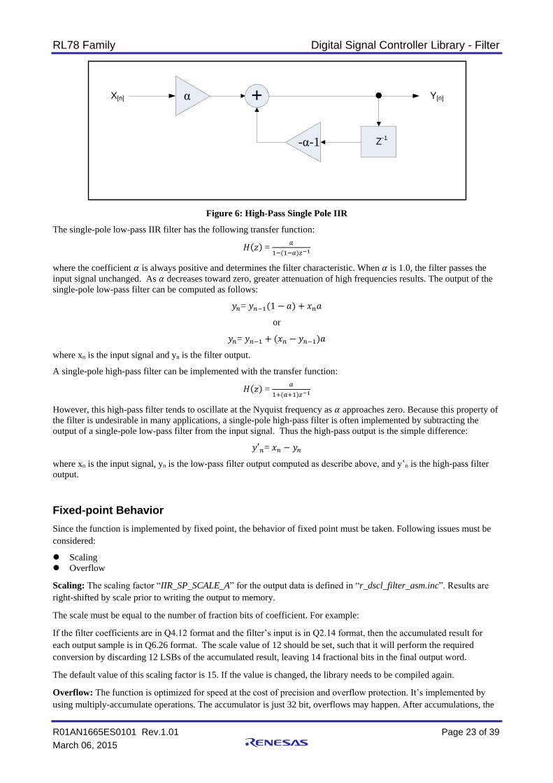
Figure 6: High-Pass Single Pole IIR
The single-pole low-pass IIR filter has the following transfer function:
𝐻(𝑧) = 𝑎
1−(1−𝑎)𝑧−1
where the coefficient 𝛼 is always positive and determines the filter characteristic. When 𝛼 is 1.0, the filter passes the
input signal unchanged. As 𝛼 decreases toward zero, greater attenuation of high frequencies results. The output of the
single-pole low-pass filter can be computed as follows:
𝑦𝑛= 𝑦𝑛−1(1 − 𝑎) + 𝑥𝑛𝑎
or
𝑦𝑛= 𝑦𝑛−1 + (𝑥𝑛 − 𝑦𝑛−1)𝑎
where xn is the input signal and yn is the filter output.
A single-pole high-pass filter can be implemented with the transfer function:
𝐻(𝑧) = 𝑎
1+(𝑎+1)𝑧−1
However, this high-pass filter tends to oscillate at the Nyquist frequency as 𝛼 approaches zero. Because this property of
the filter is undesirable in many applications, a single-pole high-pass filter is often implemented by subtracting the
output of a single-pole low-pass filter from the input signal. Thus the high-pass output is the simple difference:
𝑦′𝑛= 𝑥𝑛 − 𝑦𝑛
where xn is the input signal, yn is the low-pass filter output computed as describe above, and y’n is the high-pass filter
output.
Fixed-point Behavior
Since the function is implemented by fixed point, the behavior of fixed point must be taken. Following issues must be
considered:
Scaling
Overflow
Scaling: The scaling factor “IIR_SP_SCALE_A” for the output data is defined in “r_dscl_filter_asm.inc”. Results are
right-shifted by scale prior to writing the output to memory.
The scale must be equal to the number of fraction bits of coefficient. For example:
If the filter coefficients are in Q4.12 format and the filter’s input is in Q2.14 format, then the accumulated result for
each output sample is in Q6.26 format. The scale value of 12 should be set, such that it will perform the required
conversion by discarding 12 LSBs of the accumulated result, leaving 14 fractional bits in the final output word.
The default value of this scaling factor is 15. If the value is changed, the library needs to be compiled again.
Overflow: The function is optimized for speed at the cost of precision and overflow protection. It’s implemented by
using multiply-accumulate operations. The accumulator is just 32 bit, overflows may happen. After accumulations, the
X[n] α + Y[n]
Z-1
-α-1

RL78 Family Digital Signal Controller Library - Filter
R01AN1665ES0101 Rev.1.01 Page 24 of 39
March 06, 2015
final result is converted to 16 bit, precision is also lost. To avoid overflows completely, the input data must be scaled
down by 1 bit (Maximum is 15 bits).
Example
The following is an example showing how to use the single-pole IIR function with real 16-bit fixed-point input and
output data.
r_dscl_iirsinglepole_t myFilterHandle;
vector_t myInput; // See introduction section describing the API document
vector_t myOutput; // for a definition of the “vector_t” data type.
int16_t inputData[NUM_SAMPLES];
int16_t outputData[NUM_SAMPLES];
int16_t myIIRFlags;
int16_t mystate;
int16_t mycoeff;
/*-------------- Set up the single-pole IIR filter ------------*/
mystate = 0; // initialize state
mycoeff = (int16_t) (-0.15 * 0x7FFF);
myFilterHandle.coefs = &mycoeff;
myFilterHandle.state = &mystate;
myFilterHandle.options = R_DSCL_ROUNDING_TRUNC;
/*---------------- Set up the input/output ----------------*/
myInput.n = NUM_SAMPLES;
myInput.data = (void *)inputData;
myOutput.data = (void *)outputData;
/*------------------ Wait for input data ------------------*/
/*--------------- Main library function call --------------*/
myIIRFlags = R_DSCL_IIRSinglePole_i16i16(&myFilterHandle, &myInput,
&myOutput);
/*--------------- Output data are now ready ---------------*/
/* Note: At this point myOutput.n holds the number of output samples generated
by
* the library, where the data are written to the array pointed to by
myOutput.data.
*------------------------------------------------------------*/

RL78 Family Digital Signal Controller Library - Filter
R01AN1665ES0101 Rev.1.01 Page 25 of 39
March 06, 2015
Processing Flow
The example above just gives an example to do all the filter sample once, in this case, the input buffer and output buffer
should sufficient to hold all the data, if not, we need to filter the input sample into several times. The processing flow is
shown in Figure 7, including the setting of scaling factor.
Figure 7: Processing flow
Restrictions
The magnitude of the coefficient must be less than 1.0.
Set “IIR_SP_SCALE_A”
Compile Library
Initialization
Assign sample number to be processed, input pointer, output pointer
Call R_DSCL_ IIRSinglePole _i16i16 ()
Check sample finished?
End
No
Yes
RL78 Family Digital Signal Controller Library - Filter
R01AN1665ES0101 Rev.1.01 Page 26 of 39
March 06, 2015
4. Sample Workspace on CubeSuite+
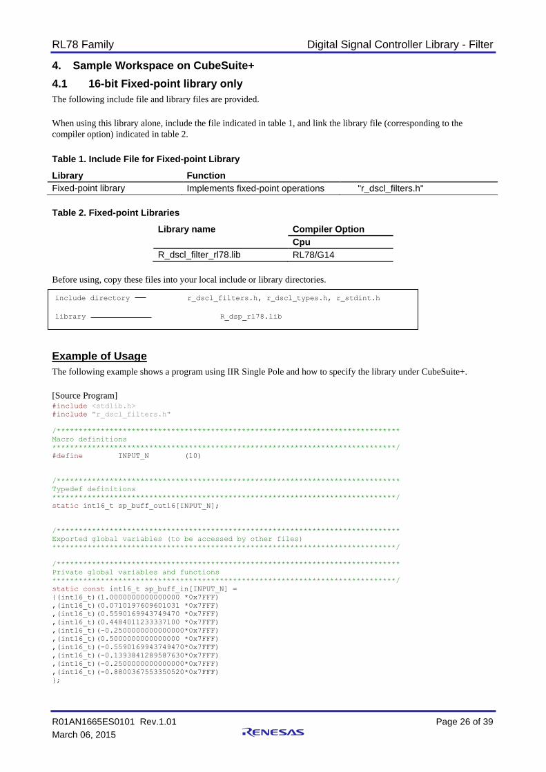
4.1 16-bit Fixed-point library only
The following include file and library files are provided.
When using this library alone, include the file indicated in table 1, and link the library file (corresponding to the
compiler option) indicated in table 2.
Table 1. Include File for Fixed-point Library
Library Function
Fixed-point library Implements fixed-point operations "r_dscl_filters.h"
Table 2. Fixed-point Libraries
Library name Compiler Option
Cpu
R_dscl_filter_rl78.lib RL78/G14
Before using, copy these files into your local include or library directories.
Example of Usage
The following example shows a program using IIR Single Pole and how to specify the library under CubeSuite+.
[Source Program] #include <stdlib.h>
#include "r_dscl_filters.h"
/******************************************************************************
Macro definitions
******************************************************************************/
#define INPUT_N (10)
/******************************************************************************
Typedef definitions
******************************************************************************/
static int16_t sp_buff_out16[INPUT_N];
/******************************************************************************
Exported global variables (to be accessed by other files)
******************************************************************************/
/******************************************************************************
Private global variables and functions
******************************************************************************/
static const int16_t sp_buff_in[INPUT_N] =
{(int16_t)(1.0000000000000000 *0x7FFF)
,(int16_t)(0.0710197609601031 *0x7FFF)
,(int16_t)(0.5590169943749470 *0x7FFF)
,(int16_t)(0.4484011233337100 *0x7FFF)
,(int16_t)(-0.2500000000000000*0x7FFF)
,(int16_t)(0.5000000000000000 *0x7FFF)
,(int16_t)(-0.5590169943749470*0x7FFF)
,(int16_t)(-0.1393841289587630*0x7FFF)
,(int16_t)(-0.2500000000000000*0x7FFF)
,(int16_t)(-0.8800367553350520*0x7FFF)
};
include directory r_dscl_filters.h, r_dscl_types.h, r_stdint.h
library R_dsp_rl78.lib

RL78 Family Digital Signal Controller Library - Filter
R01AN1665ES0101 Rev.1.01 Page 27 of 39
March 06, 2015
/******************************************************************************
* Function Name: sample_dscl_iirsinglepole
* Description : Sample code to demonstrate single-pole IIR filter
* Arguments : none
* Return Value : r_dsp_status_t Function status code
******************************************************************************/
int16_t sample_dscl_iirsinglepole (void)
{
int16_t result;
vector_t input;
vector_t * input_ptr;
vector_t output;
vector_t * output_ptr;
int16_t state;
int16_t coeff;
/*---------------------------*/
/* Single-pole IIR filter */
/*---------------------------*/
r_dscl_iirsinglepole_t sp_handle;
r_dscl_iirsinglepole_t * sp_handle_ptr;
/*---------------------------*/
/* Single-pole IIR filter */
/*---------------------------*/
state = 0;
coeff = (int16_t) (-0.15 * 0x7FFF);
sp_handle.options = R_DSCL_ROUNDING_TRUNC;
sp_handle.coefs = &coeff;
sp_handle.state = &state;
sp_handle_ptr = &sp_handle;
input.n = INPUT_N;
input.data = (void*)(&sp_buff_in[0]);
input_ptr = &input;
output_ptr = &output;
output.data = (void *)sp_buff_out16;
result = R_DSCL_IIRSinglePole_i16i16 (sp_handle_ptr,input_ptr,output_ptr);
return (result);
}
RL78 Family Digital Signal Controller Library - Filter
R01AN1665ES0101 Rev.1.01 Page 28 of 39
March 06, 2015
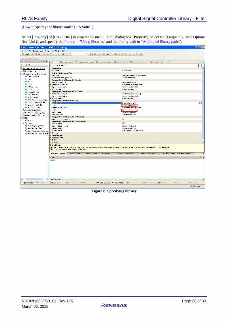
[How to specify the library under CubeSuite+]
Select [Property] of [CA78K0R] in project tree menu. In the dialog box [Property], select tab [Frequently Used Options
(for Link)], and specify the library in "Using libraries" and the library path in “Additional library paths”.
Figure 8. Specifying library

RL78 Family Digital Signal Controller Library - Filter
R01AN1665ES0101 Rev.1.01 Page 29 of 39
March 06, 2015
4.2 Resource Requirements
4.2.1 Code Size and Stack Size No. Kernel
Category
Kernel Type In/Out Format Function Options Code size
(Dec)
Total Code
size (Dec)
Stack size
(Dec)
Overall Stack
size (Dec)R_DSP_FIR_StateSize_i16i16 - 13 13 4 4
R_DSP_FIR_Init_i16i16 - 111 111 8 8
R_DSP_FIR_i16i16 c interface 189 4
R_DSP_FIR_i16i16 nr 137 20
R_DSP_FIR_i16i16 r 151 22
R_DSP_IIRBiquad_StateSize_i16i16 - 8 8 2 4
R_DSP_IIRBiquad_Init_i16i16 - 109 109 12 4
R_DSP_IIRBiquad_i16i16 c interface 174 4
R_DSP_IIRBiquad_i16i16 nr 222 28
R_DSP_IIRBiquad_i16i16 r 239 30
R_DSP_IIRSinglePole_i16i16 c interface 173 6
R_DSP_IIRSinglePole_i16i16 nr 143 22
R_DSP_IIRSinglePole_i16i16 r 172 26
i16i16
Filter Generic FIR1 i16i16
IIR-Biquad
Single-pole-IIR i16i16 488 32
635 34
477 26
Notes:
nr = R_DSP_ROUNDING_TRUNC (or no option)
r = R_DSP_ROUNDING_NEAREST
RL78 Family Digital Signal Controller Library - Filter
R01AN1665ES0101 Rev.1.01 Page 30 of 39
March 06, 2015
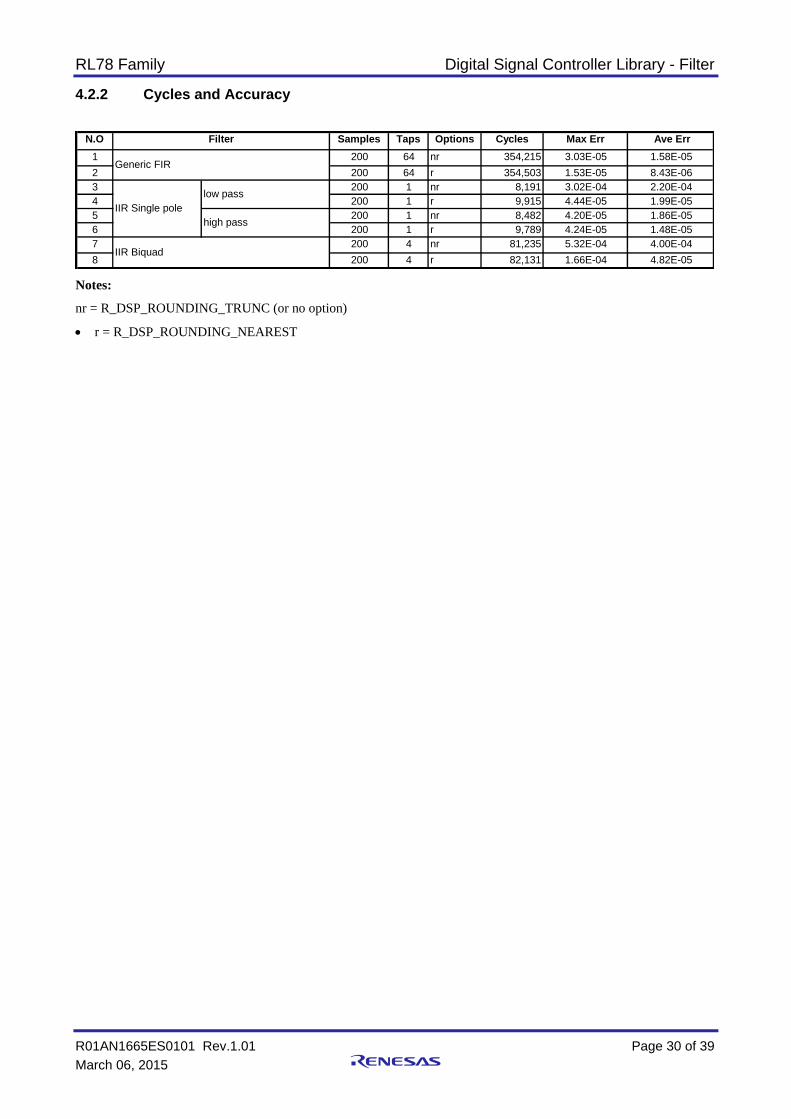
4.2.2 Cycles and Accuracy
N.O Samples Taps Options Cycles Max Err Ave Err
1 200 64 nr 354,215 3.03E-05 1.58E-05
2 200 64 r 354,503 1.53E-05 8.43E-06
3 200 1 nr 8,191 3.02E-04 2.20E-04
4 200 1 r 9,915 4.44E-05 1.99E-05
5 200 1 nr 8,482 4.20E-05 1.86E-05
6 200 1 r 9,789 4.24E-05 1.48E-05
7 200 4 nr 81,235 5.32E-04 4.00E-04
8 200 4 r 82,131 1.66E-04 4.82E-05IIR Biquad
low pass
high pass
Filter
Generic FIR
IIR Single pole
Notes:
nr = R_DSP_ROUNDING_TRUNC (or no option)
r = R_DSP_ROUNDING_NEAREST

RL78 Family Digital Signal Controller Library - Filter
R01AN1665ES0101 Rev.1.01 Page 31 of 39
March 06, 2015
5. Sample Workspace on IAR Embedded Workbench
5.1 16-bit Fixed-point library only
The following include files and library file are provided.
When using this library alone, include the file indicated in table 3, and add the library file (corresponding to the
compiler option) indicated in table 4.
Table 3. Include File for Fixed-point Library
Library Function
Fixed-point library Implements fixed-point operations "r_dscl_filters.h"
Table 4. Fixed-point Libraries
Library name Compiler Option
Cpu
R_dscl_filter_rl78.r87 RL78 core S3 - Unspecified
Before using, copy these files into your local include and library directories.
Example of Usage
The following example shows a program using IIR Single Pole and how to specify the library under IAR Embedded
Workbench.
[Source Program] #include <stdlib.h>
#include "r_dscl_filters.h"
/******************************************************************************
Macro definitions
******************************************************************************/
#define INPUT_N (10)
/******************************************************************************
Typedef definitions
******************************************************************************/
static int16_t sp_buff_out16[INPUT_N];
/******************************************************************************
Exported global variables (to be accessed by other files)
******************************************************************************/
/******************************************************************************
Private global variables and functions
******************************************************************************/
static const int16_t sp_buff_in[INPUT_N] =
{(int16_t)(1.0000000000000000 *0x7FFF)
,(int16_t)(0.0710197609601031 *0x7FFF)
,(int16_t)(0.5590169943749470 *0x7FFF)
,(int16_t)(0.4484011233337100 *0x7FFF)
,(int16_t)(-0.2500000000000000*0x7FFF)
,(int16_t)(0.5000000000000000 *0x7FFF)
include directory r_dscl_filters.h, r_dscl_types.h, r_stdint.h
library R_dscl_filter_rl78.r87

RL78 Family Digital Signal Controller Library - Filter
R01AN1665ES0101 Rev.1.01 Page 32 of 39
March 06, 2015
,(int16_t)(-0.5590169943749470*0x7FFF)
,(int16_t)(-0.1393841289587630*0x7FFF)
,(int16_t)(-0.2500000000000000*0x7FFF)
,(int16_t)(-0.8800367553350520*0x7FFF)
};
/******************************************************************************
* Function Name: sample_dscl_iirsinglepole
* Description : Sample code to demonstrate single-pole IIR filter
* Arguments : none
* Return Value : r_dsp_status_t Function status code
******************************************************************************/
int16_t sample_dscl_iirsinglepole (void)
{
int16_t result;
vector_t input;
vector_t * input_ptr;
vector_t output;
vector_t * output_ptr;
int16_t state;
int16_t coeff;
/*---------------------------*/
/* Single-pole IIR filter */
/*---------------------------*/
r_dscl_iirsinglepole_t sp_handle;
r_dscl_iirsinglepole_t * sp_handle_ptr;
/*---------------------------*/
/* Single-pole IIR filter */
/*---------------------------*/
state = 0;
coeff = (int16_t) (-0.15 * 0x7FFF);
sp_handle.options = R_DSCL_ROUNDING_TRUNC;
sp_handle.coefs = &coeff;
sp_handle.state = &state;
sp_handle_ptr = &sp_handle;
input.n = INPUT_N;
input.data = (void*)(&sp_buff_in[0]);
input_ptr = &input;
output_ptr = &output;
output.data = (void *)sp_buff_out16;
result = R_DSCL_IIRSinglePole_i16i16 (sp_handle_ptr,input_ptr,output_ptr);
return (result);
}
RL78 Family Digital Signal Controller Library - Filter
R01AN1665ES0101 Rev.1.01 Page 33 of 39
March 06, 2015
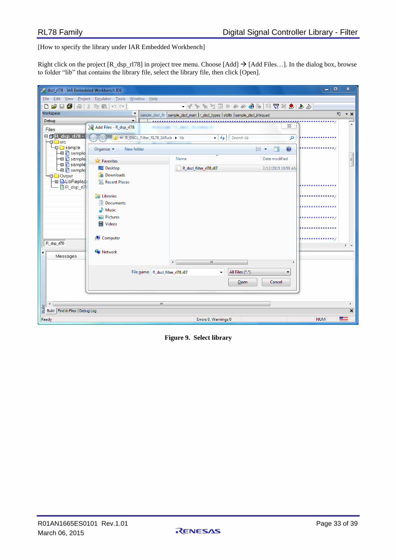
[How to specify the library under IAR Embedded Workbench]
Right click on the project [R_dsp_rl78] in project tree menu. Choose [Add] [Add Files…]. In the dialog box, browse
to folder “lib” that contains the library file, select the library file, then click [Open].
Figure 9. Select library

RL78 Family Digital Signal Controller Library - Filter
R01AN1665ES0101 Rev.1.01 Page 34 of 39
March 06, 2015
5.2 Resource Requirements
5.2.1 Code Size and Stack Size
Notes:
nr = R_DSP_ROUNDING_TRUNC (or no option)
r = R_DSP_ROUNDING_NEAREST

RL78 Family Digital Signal Controller Library - Filter
R01AN1665ES0101 Rev.1.01 Page 35 of 39
March 06, 2015
5.2.2 Cycles and Accuracy
Notes:
nr = R_DSP_ROUNDING_TRUNC (or no option)
r = R_DSP_ROUNDING_NEAREST
RL78 Family Digital Signal Controller Library - Filter
R01AN1665ES0101 Rev.1.01 Page 36 of 39
March 06, 2015
Website and Support
Renesas Electronics Website
http://www.renesas.com/ Inquiries
http://www.renesas.com/contact/
All trademarks and registered trademarks are the property of their respective owners.

A-1
Revision Record
Rev. Date
Description
Page Summary
1.00 May 7, 2012 - First Edition
1.01 March 6, 2015 - Second Edition

General Precautions in the Handling of MPU/MCU Products
The following usage notes are applicable to all MPU/MCU products from Renesas. For detailed usage notes on the
products covered by this document, refer to the relevant sections of the document as well as any technical updates that
have been issued for the products.
1. Handling of Unused Pins
Handle unused pins in accordance with the directions given under Handling of Unused Pins in the
manual.
The input pins of CMOS products are generally in the high-impedance state. In operation with an
unused pin in the open-circuit state, extra electromagnetic noise is induced in the vicinity of LSI, an
associated shoot-through current flows internally, and malfunctions occur due to the false
recognition of the pin state as an input signal become possible. Unused pins should be handled as
described under Handling of Unused Pins in the manual.
2. Processing at Power-on
The state of the product is undefined at the moment when power is supplied.
The states of internal circuits in the LSI are indeterminate and the states of register settings and
pins are undefined at the moment when power is supplied.
In a finished product where the reset signal is applied to the external reset pin, the states of pins
are not guaranteed from the moment when power is supplied until the reset process is completed.
In a similar way, the states of pins in a product that is reset by an on-chip power-on reset function
are not guaranteed from the moment when power is supplied until the power reaches the level at
which resetting has been specified.
3. Prohibition of Access to Reserved Addresses
Access to reserved addresses is prohibited.
The reserved addresses are provided for the possible future expansion of functions. Do not access
these addresses; the correct operation of LSI is not guaranteed if they are accessed.
4. Clock Signals
After applying a reset, only release the reset line after the operating clock signal has become stable.
When switching the clock signal during program execution, wait until the target clock signal has
stabilized.
When the clock signal is generated with an external resonator (or from an external oscillator)
during a reset, ensure that the reset line is only released after full stabilization of the clock signal.
Moreover, when switching to a clock signal produced with an external resonator (or by an external
oscillator) while program execution is in progress, wait until the target clock signal is stable.
5. Differences between Products
Before changing from one product to another, i.e. to a product with a different part number, confirm
that the change will not lead to problems.
The characteristics of an MPU or MCU in the same group but having a different part number may
differ in terms of the internal memory capacity, layout pattern, and other factors, which can affect
the ranges of electrical characteristics, such as characteristic values, operating margins, immunity
to noise, and amount of radiated noise. When changing to a product with a different part number,
implement a system-evaluation test for the given product.
Notice1. Descriptions of circuits, software and other related information in this document are provided only to illustrate the operation of semiconductor products and application examples. You are fully responsible for
the incorporation of these circuits, software, and information in the design of your equipment. Renesas Electronics assumes no responsibility for any losses incurred by you or third parties arising from the
use of these circuits, software, or information.
2. Renesas Electronics has used reasonable care in preparing the information included in this document, but Renesas Electronics does not warrant that such information is error free. Renesas Electronics
assumes no liability whatsoever for any damages incurred by you resulting from errors in or omissions from the information included herein.
3. Renesas Electronics does not assume any liability for infringement of patents, copyrights, or other intellectual property rights of third parties by or arising from the use of Renesas Electronics products or
technical information described in this document. No license, express, implied or otherwise, is granted hereby under any patents, copyrights or other intellectual property rights of Renesas Electronics or
others.
4. You should not alter, modify, copy, or otherwise misappropriate any Renesas Electronics product, whether in whole or in part. Renesas Electronics assumes no responsibility for any losses incurred by you or
third parties arising from such alteration, modification, copy or otherwise misappropriation of Renesas Electronics product.
5. Renesas Electronics products are classified according to the following two quality grades: "Standard" and "High Quality". The recommended applications for each Renesas Electronics product depends on
the product's quality grade, as indicated below.
"Standard": Computers; office equipment; communications equipment; test and measurement equipment; audio and visual equipment; home electronic appliances; machine tools; personal electronic
equipment; and industrial robots etc.
"High Quality": Transportation equipment (automobiles, trains, ships, etc.); traffic control systems; anti-disaster systems; anti-crime systems; and safety equipment etc.
Renesas Electronics products are neither intended nor authorized for use in products or systems that may pose a direct threat to human life or bodily injury (artificial life support devices or systems, surgical
implantations etc.), or may cause serious property damages (nuclear reactor control systems, military equipment etc.). You must check the quality grade of each Renesas Electronics product before using it
in a particular application. You may not use any Renesas Electronics product for any application for which it is not intended. Renesas Electronics shall not be in any way liable for any damages or losses
incurred by you or third parties arising from the use of any Renesas Electronics product for which the product is not intended by Renesas Electronics.
6. You should use the Renesas Electronics products described in this document within the range specified by Renesas Electronics, especially with respect to the maximum rating, operating supply voltage
range, movement power voltage range, heat radiation characteristics, installation and other product characteristics. Renesas Electronics shall have no liability for malfunctions or damages arising out of the
use of Renesas Electronics products beyond such specified ranges.
7. Although Renesas Electronics endeavors to improve the quality and reliability of its products, semiconductor products have specific characteristics such as the occurrence of failure at a certain rate and
malfunctions under certain use conditions. Further, Renesas Electronics products are not subject to radiation resistance design. Please be sure to implement safety measures to guard them against the
possibility of physical injury, and injury or damage caused by fire in the event of the failure of a Renesas Electronics product, such as safety design for hardware and software including but not limited to
redundancy, fire control and malfunction prevention, appropriate treatment for aging degradation or any other appropriate measures. Because the evaluation of microcomputer software alone is very difficult,
please evaluate the safety of the final products or systems manufactured by you.
8. Please contact a Renesas Electronics sales office for details as to environmental matters such as the environmental compatibility of each Renesas Electronics product. Please use Renesas Electronics
products in compliance with all applicable laws and regulations that regulate the inclusion or use of controlled substances, including without limitation, the EU RoHS Directive. Renesas Electronics assumes
no liability for damages or losses occurring as a result of your noncompliance with applicable laws and regulations.
9. Renesas Electronics products and technology may not be used for or incorporated into any products or systems whose manufacture, use, or sale is prohibited under any applicable domestic or foreign laws or
regulations. You should not use Renesas Electronics products or technology described in this document for any purpose relating to military applications or use by the military, including but not limited to the
development of weapons of mass destruction. When exporting the Renesas Electronics products or technology described in this document, you should comply with the applicable export control laws and
regulations and follow the procedures required by such laws and regulations.
10. It is the responsibility of the buyer or distributor of Renesas Electronics products, who distributes, disposes of, or otherwise places the product with a third party, to notify such third party in advance of the
contents and conditions set forth in this document, Renesas Electronics assumes no responsibility for any losses incurred by you or third parties as a result of unauthorized use of Renesas Electronics
products.
11. This document may not be reproduced or duplicated in any form, in whole or in part, without prior written consent of Renesas Electronics.
12. Please contact a Renesas Electronics sales office if you have any questions regarding the information contained in this document or Renesas Electronics products, or if you have any other inquiries.
(Note 1) "Renesas Electronics" as used in this document means Renesas Electronics Corporation and also includes its majority-owned subsidiaries.
(Note 2) "Renesas Electronics product(s)" means any product developed or manufactured by or for Renesas Electronics.
http://www.renesas.com
Refer to "http://www.renesas.com/" for the latest and detailed information.
Renesas Electronics America Inc.2801 Scott Boulevard Santa Clara, CA 95050-2549, U.S.A.Tel: +1-408-588-6000, Fax: +1-408-588-6130
Renesas Electronics Canada Limited9251 Yonge Street, Suite 8309 Richmond Hill, Ontario Canada L4C 9T3Tel: +1-905-237-2004
Renesas Electronics Europe LimitedDukes Meadow, Millboard Road, Bourne End, Buckinghamshire, SL8 5FH, U.KTel: +44-1628-585-100, Fax: +44-1628-585-900
Renesas Electronics Europe GmbH
Arcadiastrasse 10, 40472 Düsseldorf, GermanyTel: +49-211-6503-0, Fax: +49-211-6503-1327
Renesas Electronics (China) Co., Ltd.Room 1709, Quantum Plaza, No.27 ZhiChunLu Haidian District, Beijing 100191, P.R.ChinaTel: +86-10-8235-1155, Fax: +86-10-8235-7679
Renesas Electronics (Shanghai) Co., Ltd.Unit 301, Tower A, Central Towers, 555 Langao Road, Putuo District, Shanghai, P. R. China 200333Tel: +86-21-2226-0888, Fax: +86-21-2226-0999
Renesas Electronics Hong Kong LimitedUnit 1601-1611, 16/F., Tower 2, Grand Century Place, 193 Prince Edward Road West, Mongkok, Kowloon, Hong KongTel: +852-2265-6688, Fax: +852 2886-9022
Renesas Electronics Taiwan Co., Ltd.13F, No. 363, Fu Shing North Road, Taipei 10543, TaiwanTel: +886-2-8175-9600, Fax: +886 2-8175-9670
Renesas Electronics Singapore Pte. Ltd.80 Bendemeer Road, Unit #06-02 Hyflux Innovation Centre, Singapore 339949Tel: +65-6213-0200, Fax: +65-6213-0300
Renesas Electronics Malaysia Sdn.Bhd.Unit 1207, Block B, Menara Amcorp, Amcorp Trade Centre, No. 18, Jln Persiaran Barat, 46050 Petaling Jaya, Selangor Darul Ehsan, MalaysiaTel: +60-3-7955-9390, Fax: +60-3-7955-9510
Renesas Electronics India Pvt. Ltd.No.777C, 100 Feet Road, HALII Stage, Indiranagar, Bangalore, IndiaTel: +91-80-67208700, Fax: +91-80-67208777
Renesas Electronics Korea Co., Ltd.12F., 234 Teheran-ro, Gangnam-Gu, Seoul, 135-080, KoreaTel: +82-2-558-3737, Fax: +82-2-558-5141
SALES OFFICES
© 2015 Renesas Electronics Corporation. All rights reserved.
Colophon 5.0
Related Documents