1 RITES LTD. E-TENDERING DOCUMENT FOR WORKS “Construction of (12 nos Type –II, 9 nos Type-III and 4 nos Type-IV) Quarters, Railway office, Trip Shed, OHE Depot, Tower Wagon Shed, P-way works and other Building works, Road works & General Electrical work including all other Civil & Electrical ancillary works between LMG(Excl) and BPB in connection with Rly Electrification of Lumding - Badarpur Single section under Lumding Division of Northeast Frontier Railway (NFR), Assam, India.” PART-I (TECHNICAL BID) TENDER No.: 16/OT/RITES/NFR/LMG-BPB/Civil-P-way-GE/2021 Dated. 25.09.2021 SEPTEMBER - 2021 (A GOVT. OF INDIA ENTERPRISE) RITES LIMITED, Regional Project Office, KOLKATA 56, C. R. Avenue, 2nd floor, Kolkata – 700 012 Email: [email protected] Phone No: (033) 2236 7118/7146/7162/7143(Fax)

Welcome message from author
This document is posted to help you gain knowledge. Please leave a comment to let me know what you think about it! Share it to your friends and learn new things together.
Transcript

1
RITES LTD.
E-TENDERING DOCUMENT
FOR WORKS
“Construction of (12 nos Type –II, 9 nos Type-III and 4 nos
Type-IV) Quarters, Railway office, Trip Shed, OHE Depot,
Tower Wagon Shed, P-way works and other Building works,
Road works & General Electrical work including all other
Civil & Electrical ancillary works between LMG(Excl) and
BPB in connection with Rly Electrification of Lumding -
Badarpur Single section under Lumding Division of
Northeast Frontier Railway (NFR), Assam, India.”
PART-I (TECHNICAL BID)
TENDER No.: 16/OT/RITES/NFR/LMG-BPB/Civil-P-way-GE/2021
Dated. 25.09.2021
SEPTEMBER - 2021
(A GOVT. OF INDIA ENTERPRISE)
RITES LIMITED,
Regional Project Office, KOLKATA 56, C. R. Avenue, 2nd floor, Kolkata – 700 012
Email: [email protected] Phone No: (033) 2236 7118/7146/7162/7143(Fax)

2
SECTION- 1
NOTICE INVITING TENDER AND
INSTRUCTIONS TO TENDERERS

3
SECTION 1
NOTICE INVITING TENDER AND INSTRUCTIONS TO TENDERERS TENDER No.: 16/OT/RITES/NFR/LMG-BPB/Civil-P-way-GE/2021 Dt. 25.09.2021
1.0 GENERAL
1.1 Tender Notice
Tenders are invited through E-Tendering system by RITES Ltd., a Public Sector Enterprise
under the Ministry of Railways, acting for and on behalf of Northeast Frontier Railway, Ministry of Railways (Railway Board)(Employer) as an Agent/Power of Attorney Holder,
from working contractors (including contractors who have executed works within the last seven years reckoned from the scheduled date of opening of tender) of Railways, CPWD,
MES, DOT, RITES, State PWD or any other Central/State Government Department,
Central/State Government Undertaking or their subsidiaries, Municipal Body, Autonomous
Body of Central / State Governments or Public Ltd., Companies listed on Stock Exchange
in India or Abroad or subsidiaries of such companies for the work of “Construction of (12
nos Type –II, 9 nos Type-III and 4 nos Type-IV) Quarters, Railway office, Trip Shed,
OHE Depot, Tower Wagon Shed, P-way works and other Building works, Road
works & General Electrical work including all other Civil & Electrical ancillary
works between LMG(Excl) and BPB in connection with Rly Electrification of
Lumding - Badarpur Single section under Lumding Division of Northeast Frontier
Railway (NFR), Assam, India.”
(Note: Throughout these bidding documents, the terms ‘bid’ and ‘tender’ and their
derivatives are synonymous)
1.2 Estimated Cost of Work
The work is estimated to cost Rs. 43,97,81,242/- (Rupees Forty Three Crore
Ninety Seven Lakh Eighty One Thousand Two Hundred Forty Two only) excluding
GST. The estimate is generally based on approved rates of NFR-USSOR-2010, DSR-2018,
LAR of RITES etc. This Estimate, however, is given merely as a rough guide.
1.3 Time for Completion
The time allowed for completion will be 14 (Fourteen) months from the date of start
whichis defined in Schedule- F under Clause 5.1(a) of Clauses of Contract. 1.4 Brief Scope of Work
• Construction of Staff Quarters, Office, OHE Depot, TSS, TWS, IPS, Battery Rooms,
Trip Shed , Road work and other Building works etc.
• Supply of Cement and Steel Reinforcement.
• Any arrangements required for holding OHE Masts/structures on Bridge
proper/Tunnels.
• P-way work including linking, lowering of Track, Construction of Inspection Pit and
other allied P-Way works.
• Supply of Rail, Ballast, Sleepers Points & Crossings, P-Way fittings etc.
The proposed work also includes General Electrical Works which are as follows:
• Electrification of Staff Qtrs. & Colony., T/W Shed, AEE/ASTE Office, OHE/PSI Depot, Relay Room ,Trip Shed, TSS Control Room & Yard Lighting
4
• Provision of Drawing & Design (Location Drawing, Lux Calculation, Cable/wire
laying route design) for Internal electrification work &30 mtr long High Mast
with LED luminaries and 7 mtr long Octagonal pole for Pathway Illumination at
colony/township.
• Supply, Erection, Testing & commissioning of High Mast & Octagonal poles.
• Training for maintenance of High Mast along with Luminaries, substation items
etc.
• Preparation of “As Erected Drawings” (Layout Plan of high mast and cable,
Connection diagram, Single Line Diagram, lux calculation) furnishing 4 copies
and 1 nos. of Tracing for each drawing after approval.
• Co-ordination & Liaisioning with the office of Sr.DEE and CEE regarding design drawing execution and commissionng of Electrical General work as well as with
state electricity authorities regarding power supply if any.
• And all allied works necessary for successful completion and commissioning of
the project including Maintenance & supervision of entire system during defect
liability period of the project
1.5 Availability of Site
The site for the subject work is mostly available.
1.6 Deadline for submission of bids is 11:00 hrs on 18.10.2021
The Employer may extend the deadline for submission of Tenders by issuing an
amendment in writing in accordance with Clause 6.3. The Employer may extend the
deadline for submission of bids and/or the bid opening date and time, even otherwise, if
it considers the same to be desirable / expedient. In case of such extension, all rights and
obligations of the Employer and the Tenderer previously subject to the original deadline
will be subject to new deadline. All Bidders are advised to see the website
https://etenders.gov.in/eprocure/app for extension of deadline for submission of tenders
and/or the bid opening date.
CRITICAL DATA SHEET
Published Date 27.09.2021 at 18:00 hrs
Bid Document Download / Sale Start Date 27.09.2021 at 18:30 hrs
Pre-bid Query Receipt Start Time & Date NOT APPLICABLE
Pre-bid Query Receipt End Time & Date NOT APPLICABLE
Bid submission Start Date & Time 28.09.2021 AT 11:00 HRS
Bid submission End Date & Time 18.10.2021 AT 11;00 HRS
Bid Opening Date & Time 19.10.2021 AT 11:30 HRS
*‘Bid opening date and time’ should not be less than 24 hours of the ‘Bid submission End Date
& Time’
2.0 QUALIFICATION CRITERIA TO BE SATISFIED
2.1 The Qualification Criteria to be satisfied are given at Annexure-I enclosed.
2.2 The Qualification Criteria to be satisfied will depend on the category of works, whether
Small, Normal or Large. Small Works are those costing up to and including Rs. 3 Crore,
Normal Works are those costing above Rs. 3 Crore and up to and including Rs. 100 Crore
each and Large Works are those costing above Rs. 100 Crore. The work for which the
Tender is being invited falls under the category of Normal Works

5
2.3 The Qualification Criteria to be satisfied will also depend on whether the Work falls in
Normal area or difficult area. Difficult area includes North East States, Jammu & Kashmir,
Ladakh, Andaman & Nicobar Islands and the 60 districts requiring Integrated Action Plan
of Government of India (List available at Annexure X). Normal area covers all areas other
than difficult area. The work for which this Tender has been invited falls under Difficult
area.
(*Strike out whichever is not applicable)
2.4 In this tender Joint Venture is not allowed
+
In case joint Venture is allowed the following will apply:
a) If JV is successful in the Bid, the Contract will be awarded in the name of JV. The JV
Agreement should be executed within 15 days of receipt of Letter of Acceptance and
the JV Agreement duly registered in accordance with law so as to be legally valid and
binding on the members. The JV shall also open a Bank account in the name of JV
and all payments due to the JV shall be credited by the Employer to that account only.
To facilitate statutory deductions such as towards Income Tax etc. made from the
amounts due to the JV being credited to the concerned Government Departments, the JV shall arrange to obtain in the name of JV, PAN/TIN etc. as required.
b) Bid submitted by a Joint Venture of two or more firms as Partners/Members shall be
accompanied by the following documents:
I. A copy of Joint Venture MOU/Agreement duly notarized so as to be legally valid and binding on all the Partners/Members and incorporating the following
provisions (Suggested format at Annexure II) should be uploaded:
i. The Bid and, in case of a successful Bid, the Agreement shall be signed so as to
be legally binding on all Partners/Members.
ii. One of Partners/Members shall be nominated as being in charge and this
authorization shall be evidenced by submitting Power of Attorney signed by
legally authorized signatories of all the Partners/Members.
iii. The Partner-in-charge/Lead Member shall be authorized to incur liabilities and
receive instructions for and on behalf of any and all partners/members of the Joint
Venture and entire execution of the Contract, shall be done exclusively with the
Partner in charge.
iv. All the partners of the Joint Venture shall be liable jointly and severally for the execution of the contract in accordance with the Contract terms and a statement to
this effect shall be included in the authorization through a Power of Attorney in favour of the Partner-in-charge/Lead Member as well as in the Bid and in the
Agreement (in case of a successful bid).
v. Indication of the precise responsibility of all the Partners/Members of the Joint
Venture in respect of planning, design, construction equipment, key personnel,
work execution and financing of the Project duly indicating the percentage in
financing of JV by each Partner.

6
vi. In case of Large Works, the maximum number of Partners can be only three and
the Partner-in-Charge/Lead Member shall have more than 50% participation in
financing of the JV and each of the other Members minimum 20% participation in
financing of JV. In case of ‘Normal Works’ the Partner-in-Charge/Lead Partner
shall be responsible for 100% financing of the JV.
vii. All partners/members of the JV shall comply with the provisions in the Integrity Pact and any violation of the Pact by any partner/member shall be construed as a
violation by the JV.
II. Power of Attorney in favour of the Partner-in-charge/Lead Member on the lines mentioned in item “a” above. (Suggested format at Annexure IV)
2.5 The documents to be furnished by the Bidder to prove that he is satisfying the qualification
Criteria laid down should all be in the Bidder’s name, except in cases where through the
name has changed, the owners continued to remain the same and in cases of amalgamation
of entities.
3.0 FORMAT AND CHECK LIST FOR SUBMISSION OF INFORMATION ON
QUALIFICATION CRITERIA
3.1 The information to be furnished and the documents to be enclosed shall be as per Clause
28.0
Herein after. Documents/information complete in all respects, in support of meetingthe
Qualification Criteria should be submitted in one go. Submission of additional documents
shall not be permitted. Only clarifications and filling of gaps/missing information in the
submitted documents, may be permitted.
4.0 CONTENTS OF TENDER DOCUMENT
4.1 Each set of Tender or Bidding Document will comprise the documents listed below and addenda issued in accordance with Clause 6:
PART-1: - Technical Bid Packet
(Read with Correction Slip Nos. 1 to 9)
Section-1 Notice Inviting Tender andInstructions to Tenderers including Annexures
Section-2 Tender and Contract Form [DELETED]
Section-3 Special Conditions
Section-4 Schedules A to F
Section-5 TECHNICAL SPECIFICATIONS
Section-6 Drawing
PART-2: - FINANCIAL BID PACKET
Schedule of Quantities (Bill of Quantities)

7
PART-3: - General Conditions of Contract
(Read with Correction Slip Nos. 1 up to 10)
Section-7 Conditions of Contract
Section-8 Clauses of Contract
Section-9 RITES Safety Code
Section-10 RITES Model Rules for Protection of Health and Sanitary Arrangements
for Workers
Section-11 RITES Contractor’s Labour Regulations
4.2 Part-3:General Conditions of Contract (Compilation of section 7 to 11) as also Correction
Slips to GCC are available on RITES websitewww.rites.com under the link
‘Tenders’.
4.3 Part-3 of the tender, i.e., General Conditions of Contract (Compilation of Section 7 to 11) is
not uploaded as a part of this tender document because as stated in sub-clause 4.2 above,
the same is available separately on RITES’ website and can be seen/downloaded from
there. The bidder need not submit/upload Part 3 of the tender as a part of his offer. So
far as Part-1 is concerned, the bidder is required to submit/upload only the
documents mentioned in Clause 28.0 of Section 1 thereof. Rest of the Part-1 need not
be uploaded. The bidder must, nevertheless, read the same. It shall bepresumed that
the bidder has read the contents of Part 1: Technical Bid Packet and Part 3: General
Conditions of Contract and upto date Correction Slips thereto and the same will be
binding upon him. The successful bidder will be required to sign the complete tender document i.e., Part 1, Part 2, Part 3 and Correction Slips, if any, thereto.
5.0 INSTRUCTIONS ON ACCESSING/PURCHASING OF BID DOCUMENTS AND
SUBMISSION THEREOF
5.1 To participate in the E-Bid submission for RITES, it is mandatory for the bidders to get their firms registered with E-Procurement Portal https://etenders.gov.in/eprocure/app
5.2 The bidders are required to submit soft copies of their bids electronically on the CPP
Portal, using valid Digital Signature Certificates. The instructions given below are meant to
assist the bidders in registering on the CPP Portal, prepare their bids in accordance with the
requirements and submitting their bids online on the CPP Portal.
5.3 REGISTRATION
a) Bidders are required to enroll on the e-Procurement module of the Central Public
Procurement Portal (URL: https://etenders.gov.in/eprocure/app) by clicking on the
link “Online Bidder Enrolment” on the CPP Portal which is free of charge.
b) As part of the enrolment process, the bidders will be required to choose a unique username and assign a password for their accounts.
c) Bidders are advised to register their valid email address and mobile numbers as part
of the registration process. These would be used for any communication from the CPP Portal.

8
d) Upon enrolment, the bidders will be required to register their valid Digital Signature
Certificate (Class III Certificates with signing key usage) issued by any Certifying
Authority recognized by CCA India with their profile.
e) Only one valid DSC should be registered by a bidder. Please note that the bidders are
responsible to ensure that they do not lend their DSC’s to others which may lead to
misuse.
f) Bidder can log in to the site through the secured log-in by entering their user ID/Password and the password of the DSC/e-Token.
5.4 SEARCHING FOR TENDER DOCUMENTS
a) There are various search options built in the CPP Portal, to facilitate bidders to
search active tenders by several parameters. These parameters could include Tender
ID, Organization Name, Location, Date, Value, etc. There is also an option of
advanced search for tenders, wherein the bidders may combine a number of search
parameters such as Organization Name, Form of Contract, Location, Date, Other
keywords etc. to search for a tender published on the CPP Portal.
b) Once the bidders have selected the tenders they are interested in, they may download
the required documents/tender schedules. These tenders can be moved to the
respective ‘My Tenders’ folder. This would enable the CPP Portal to intimate the
bidders through SMS/E-mail in case there is any corrigendum issued to the tender
document.
c) The bidder should make a note of the unique Tender ID assigned to each tender, in case they want to obtain any clarification/help from the Helpdesk.
5.5 PREPARATION OF BIDS
a) Bidder should take into account any corrigendum published on the tender document
before submitting their bids.
b) Bidder is advised to go through the tender advertisement/NIT and the tender
document carefully to understand the documents required to be submitted as part of
the bid. Bidder may please note the number of covers in which the bid documents
have to be submitted, the number of documents – including the names and content of
each of the document that need to be submitted. Any deviations from these may lead
to rejection of the bid.
c) Bidder, in advance, should get ready the bid document to be submitted as indicated in
the tender document/schedule and generally, they can be in PDF/XLS/RAR/JPG
formats. Bid documents may be scanned with 100 dpi with black and white option
which helps in reducing size of the scanned document.
d) To avoid the time and effort required in uploading the same set of standard documents which are required to be submitted as a part of every bid, a provision of uploading
such standard documents (e.g. PAN Card copy, Annual Reports, Auditor Certificates etc.) has been provided to the bidders. Bidders can use “My Space” or “Other
Important Documents” area available to them to upload such documents. These documents may be directly submitted from the “My Space” area while submitting a
bid, and need not be uploaded again and again. This will lead to a reduction in the time required for bid submission process.

9
5.6 SUBMISSION OF BIDS
a. Bid can be submitted only during validity of registration of bidder with CPPP E-
Procurement Portal.
b. Bidder should log into the site well in advance for bid submission so that they can upload the bid in time i.e. on or before the bid submission time. Bidder will be
responsible for any delay due to other issues.
c. The Bidder has to digitally sign and upload the required bid documents one by one as indicated in the tender document.
d. Bidder has to select the payment option as “offline” to pay the cost of tender
document and EMD as applicable and enter details of the instruments.
e. Bidder should prepare the financial instruments of the Cost of Tender Documents and
EMD as per the instructions specified in Clause 7.0 (f) hereinafter. The original
should be posted/couriered/given in person to the concerned official, so as to reach
him within a week from the date of opening. The details of the DD/any other accepted
instrument, physically sent, should tally with the details available in the scanned copy
and the data entered during bid submission time. If the date of issue of DD/any other
accepted instrument, physically sent, is on or before the bid submission end date, the
same shall also be accepted even if the details are differentfrom the scanned copy
uploaded along with the bid. Otherwise, the uploaded bid will be rejected.
f. Bidders are requested to note that they should necessarily submit their financial bids in the format provided and no other format is acceptable. If the price bid has been
given as a standard BOQ format with the tender documents, then the same is to be downloaded and to be filled by all the bidders. Bidders are required to download the
BOQ file, open it and complete the Sky Blue coloured (unprotected) cells with their respective financial quotes and other details (such as name of the bidder). No other
cells should be changed. Once the details have been completed, the bidder should save it and submit it online, without changing the filename. If the BOQ file is found
to be modified by the bidder, the bid will be rejected.
g. The server time (which is displayed on the bidders’ dashboard) will be considered as
the standard time for referencing the deadlines for submission of the bids by the
bidders, opening of bids etc. The bidders should follow this time during bid
submission.
h. All the documents being submitted by the bidders would be encrypted using PKI
encryption techniques to ensure the secrecy of the data. The data entered cannot be
viewed by unauthorized persons until the time of bid opening. The confidentiality of
the bids is maintained using the secured Socket Layer 128 Bit encryption technology.
Data storage encryption of sensitive fields is done. Any bid document that is uploaded
to the server is subjected to symmetric encryption using a system generated symmetric key. Further this key is subjected to asymmetric encryption using
buyers/bid opener’s public keys.
i. The uploaded tender documents become readable only after the tender opening by the authorized bid openers.

10
j. Upon the successful and timely submission of bids (i.e. after clicking “Freeze Bid
Submission” in the portal), the portal will give a successful bid submission
message&a bid ID to the bid. A bid summary will be displayed with the bid ID and
the date&time of submission of the bid with all other relevant details.
k. The bid summary has to be printed and kept as an acknowledgement of the
submission of the bid. This acknowledgement may be used as an entry pass for any bid opening meetings.
5.7 ASSISTANCE TO BIDDERS
a) Any queries relating to the process of online bid submission or queries relating to CPP Portal in general may be directed to the 24x7 CPP Portal Help Desk Number
0120-4200462, 0120-4001002, 0120-4001005, 0120-6277787, E-mail id: [email protected]
b) Bidders information useful for submitting online bids on the CPP Portal may be
obtained at: https://etenders.gov.in/eprocure/app?page=BiddersManualKit &service=page
c) It is mandatory for all bidders to have Class-III Digital Signature Certificate (DSC) in
the name of the person along with name of Company who will digitally sign thebid
from any of licensed Certifying Agency (CA). Bidders can see the list of licensed
CAs from the link https://www.cca.gov.in
d) Bidder shall ensure use of registered Digital Signature Certificate (DSC) only and safety of the same.
e) In case the Digital Signature Certificate (DSC) holder who is digitally signing the bid and the person having Authority to Sign as per Clause 11 are different, even then all
the terms and conditions of the tender document will be binding upon the bidder.
5.8 CLARIFICATIONS ON TENDER DOCUMENTS
A prospective Tenderer requiring any clarification on the Tender Document may notify
through queries, on line only within the specified period (refer clause 1.6-Critical Date
Sheet hereinbefore) Request for clarifications including request for Extension of Time for submission of Bid,
if any, must be received not later than 10 (ten) days prior to the deadline for submission of tenders. Details of such queries raised and clarifications furnished will be uploaded in
CPP website https://etenders.gov.in/eprocure/app without identifying the names of the bidders who had raised the queries. Any modification of the Tender Document arising out
of such clarifications will also be uploaded on CPP website.
6.0 AMENDMENT OF TENDER DOCUMENT
6.1 Before the deadline for submission of tenders, the Tender Document may be modified by
RITES Ltd. by issue of addenda/corrigendum.
6.2 Addendum/Corrigendum, if any, will be hosted on website
https://etenders.gov.in/eprocure/app and shall become a part of the tender document. All
tenderers are advised to see the website for addendum/corrigendum to the tender
document which may be uploaded up to 7 days prior to the deadline for submission of
tender as finally stipulated.

11
6.3 To give prospective tenderers reasonable time in which to take the addenda/corrigenda
into account in preparing their tenders, extension of the deadline for submission of
tenders may be given before bid submission end date and time as considered necessary by
RITES. Sometimes due to administrative reasons, the deadline for submission of tenders
may be extended latest by the deadline for opening of tender as stipulated including
extension given earlier. All tenderers are advised to see the website for extension of deadline for submission of tenders.
6.4 Tenderer who has downloaded the tender from Central Public Procurement Portal (CPPP)
website https://etenders.gov.in/eprocure/app shall not tamper/modify the tender form including downloaded Price Bid Template in any manner. In case if the same is found to
be tampered/modified in any manner, tender will be completely rejected and EMD would be forfeited and tenderer is liable to be banned from doing business with RITES Ltd.
7.0 PREPARATION AND SUBMISSION OF BIDS
(a) Part-1 and Part-2 of tender document may be downloaded from CPPP and Part-3 from
RITES website https://www.rites.com under the link ‘Tender’ – ‘RITES GCCfor
Works’ well before the deadline for submission of bids. The bids (Part-2 only)
alongwith the information and documents specified in Clause 28.0hereinafter shall be
submitted online following the instructions appearing on the screen. Documents
specified in Clause 28.0 of Section 1, Part-1 are required to be uploaded along
with Part-2 (Financial Bid); the rest of Part-1 and the whole of Part-3 of the
tender document need not be submitted online but it shall be deemed to have
been submitted. Users are requested to map their system as per the System
settingsavailable on the link https://etenders.gov.in/eprocure/app?page=BiddersManualKit&service=page on the
CPP portal.
(b)Afterdownloading/getting the tender document/schedules from https://etenders.gov.in/eprocure/app the Bidder should go through them carefully and
then submit the documents as asked, otherwise bid will be rejected. It is construed that the bidder has read all the terms and conditions before submitting their offer.
Bidders are advised that prior to bid submission they should read the bidsubmission
manual available on CPP Portal
https://etenders.gov.in/eprocure/app?page=BiddersManualKit&service=pageweb
site
(c) Bidders may ensure that all the pages of the documents mentioned in Clause 28.0
must be signed & stamped by authorized signatory and serially numbered. In case, it
is found that bidder has not complied with the same, the documents shall be deemed
to be signed and stamped as this is a digitally signed e-tender.
(d) The bids shall be submitted online following the instructions appearing on the screen.
Bidders may insert their e-Token/Smart Card in their computer and Log onto CPP
portal https://etenders.gov.in/eprocure/app using the User-Id and Password chosen during registration. Then they may enter the password of the e-Token/Smart Card to
access the DSC.
(e) Prior to bid submission, bidder should get ready with the documents to be uploaded as part of the bid as indicated in the tender document/schedule. Generally, they can be in
Excel/PDF/RAR/JPG formats. No other format is accepted. If there is more than one PDF document, then they can be clubbed together in a Zip file for uploading. There is

12
no limit for uploading file. Bids shall be submitted online only at CPP website
https://etenders.gov.in/eprocure/app
Tenderer/Contractor are advised to follow the instructions provided in the
‘Instructions to the Contractors/Tenderer for the e-submission of the bids online
through the Central Public Procurement Portal for e procurement at
https://etenders.gov.in/eprocure/app
Bid documents may be scanned with 100 dpi with black and white option which helps in reducing size of the scanned document.
Intending tenderers are advised to visit CPPP website
https://etenders.gov.in/eprocure/app till the specified date and time of opening of tender to check if there is any extension of deadline of submission of tender.
(f) Cost of Tender Document & Earnest Money Deposit (EMD)
During bid submission the bidder has to select the payment option as offline to pay
the Cost of Tender Document and EMD and enter details of the instruments. In case
of exemption from payment of cost of tender document and EMD as a matter of Govt.
Policy, the scanned copy of document in support of exemption will have to be
uploaded by the bidder during bid submission. In case the bidder is registered as a
vendor under the category of Micro, Small and Medium Enterprises (MSME), he
must state his Udyog Aadhar Memorandum (UAM) number as registered on CPPP.
The onus of proving that the bidder is exempted from payment of cost of tender
document and/or EMD lies on the bidder. In this connection, it should be noted that
mere opening of bid does not mean that the bid has to be considered by RITES as a valid bid. If later, it is discovered from the uploaded documents that bidder is not
exempted from payment of cost of tender and/or EMD, his bid shall be treated as non-responsive. It may be noted that the benefits under Public Procurement Policy for
Micro and Small Enterprises (MSEs) Order, 2012 are applicable to only Supply and Service Contracts.
i. Cost of Tender Document: The Cost of Tender Document is Rs.18,000/-
(Rupees Eighteen Thousand only) which is non-refundable. It shall be in the
form of a Banker’s Cheque/Pay Order/Demand draft favouring “RITES Ltd.”
issued by a scheduled Commercial Bank, payable at KOLKATA. No other mode
of payment will be acceptable.
Earnest Money Deposit (EMD):
I. The Bidders/tenderers are not required to deposit the Earnest Money (Bid
Security) along with the bid documents. In place of Earnest Money, it is
mandatory that the Bidders/ tenderers shall submit Bid Security Declaration
(As per Annexure XI to NIT & ITT) along with the Bid Documents. Refer
GCC July-2019 Correction Slip No- 9
II. Any tender not accompanied by Bid Security Declaration shall be rejected
outright.
III. Other terms and conditions related to Security Deposit will remain
unchanged.

13
Bidders are required to upload scanned copy of acceptable instruments for cost of
Tender document in different files (Either in PDF or Zip format) during on-line
submission of Bid. These documents shall be deposited in “ORIGINAL” in a
sealed envelope within a week from the date of opening of Technical bid to:
The General Manager (P)/RPO-Kolkata, Project Office, RITES Ltd., 56, C.R. Avenue, 2nd Floor, Kolkata – 700012.
Failing which the bid shall be rejected and the bidder shall be debarred from
tendering in RITES Ltd. for a period of 02 (two) years unless the lapse is
condoned by the Accepting Authority at the request of the bidder for valid
reasons. The envelope should bear the tender details (Tender No., Tender
Name etc.)
(g) The bid should be submitted online in the prescribed format. No other mode of
submission is accepted.
(h) Bid shall be digitally signed by a representative of the bidder and submitted “on-line”.
No hard copies of the documents (except those specifically asked for in the tender
document) are required to be submitted.
(i) The bidders will have to accept unconditionally the online user portal agreement
which contains the Terms and Conditions of NIT including General and Special Terms & Conditions and other conditions, if any, along with on-line undertaking in
support of the authenticity regarding the facts, figures, information and documents furnished by the bidder on-line in order to become an eligible bidder.
(j) The bidder has to digitally sign and upload the required bid documents one by one as
indicated. Bidders to note that the very act of using DSC for downloading the bids and uploading their offers shall be deemed to be a confirmation that they have read all
sections and pages of the tender/bid document including terms and conditions without
any exception and have understood the entire document and are clear about tender
requirements which will be binding upon the bidder.
(k) The bidders are requested to submit the bids through online e-tendering system before
the deadline for submission of bids (as per Server System Clock displayed on the
portal). RITES will not be held responsible for any sort of delay or the difficulties
faced during online submission of bids by the bidders at the eleventh hour.
(l) The bidder may seek clarification online only within the specified period. The identity
of bidder will not be disclosed by the system. RITES Ltd. will clarify the relevant queries of bidders as far as possible. The clarifications given will be visible to all the
bidders intending to participate in that tender. The clarifications may be asked from the day of “Pre Bid Query Receipt Start Date and Time” till “Pre Bid Query Receipt
End Date and Time”.
8.0 TENDER VALIDITY
8.1 The Tender shall be valid for a period of 90 days from the due date for submission of
Tender or any extended date as indicated in sub para below.

14
8.2 In exceptional circumstances, during the process of evaluation of tenders and prior to the
expiry of the original time limit for Tender Validity, the Employer may request that the
Tenderers may extend the period of validity unconditionally for a specified additional
period. The request and the tenderer’s response shall be made in writing/ e-mail. A
Tenderer may refuse the request without forfeiting his Earnest Money. A Tenderer
agreeing to the request will not be permitted to modify his Bid but will be required to
extend the validity of the Earnest Money for the period of the extension.
9.0 EARNEST MONEY - Refer GCC July-2019 Correction Slip No. 9
9.1 The Bidders/tenderers are not required to deposit the Earnest Money (Bid Security) along with the bid documents. In place of Earnest Money, it is mandatory that the Bidders/
tenderers shall submit Bid Security Declaration (Annexure XI to NIT & ITT) along with the Bid Documents. Refer GCC July-2019 Correction Slip No. 9
9.2 Any Tender not accompanied by scanned copies of the instruments for payment of Earnest Money(Earnest Money now to be replaced by Bid Security Declaration as per Annexure – XI) and cost of tender document in an acceptable form (or, if applicable, the scanned copy of document in support of exemption) shall be rejected by the Employer as non-responsive.
9.3 Refund of Earnest Money (DELETED) (Refer GCC July-2019 Correction Slip No.
9)
9.4 The Earnest Money is liable to be forfeited- DELETED
10.0 MODIFICATION/ SUBSTITUTION/WITHDRAWL OF BIDS
10.1 The Tenderers shall submit offers which comply strictly with the requirements of the Tender Document as amended from time to time as indicated in Clause 6.0 above.
Alternatives or any modifications by the tenderer shall render the Tender invalid.
10.2 The bidder can modify, substitute, re-submit or withdraw its E–bid after submission but
prior to the deadline for submission of bids or the extended deadline, as the case may be.
No Bid shall be modified, substituted or withdrawn by the bidder on or after the deadline
for submission of bids or the extended deadline, as the case may be. Withdrawal of bid
after such deadline would result in the forfeiture of EMD.
10.3 Any modification in the Bid or additional information supplied subsequently to the
deadline for submission of bids or the extended deadline, as the case may be, unless the same has been explicitly sought for by RITES, shall be disregarded.
10.4 For modification of E–bid (Technical Bid), bidder has to detach its old bid from CPP
portal and upload / re-submit digitally signed modified bid.
10.5 For withdrawal of bid, bidder has to click on withdrawal icon at CPP portal and can
withdraw its E–bid.
10.6 After the bid submission on the portal, an acknowledgement number will be generated by
the system which should be printed by the bidder and kept as a record of evidence for
online submission of bid for the particular tender and will also act as an entry pass to
participate in the bid opening.
10.7 The time settings fixed in the server side & displayed at the top of the tender site, will be
valid for bid submission, in the e-tender system. The bidders should follow this time during bid submission.
15
10.8 All the data being entered by the bidders would be encrypted using PKI encryption
techniques to ensure the secrecy of the data. The data entered will not be viewable by
unauthorized persons during bid submission & will not be viewable by any one until the
date & time specified for bid opening.
10.9 The bidder should logout of the tendering system using the normal logout option
available in the portal and not by selecting the (X) exit option in the browser.
11.0 AUTHORITY TO SIGN
a) If the applicant is an individual, he should sign above his full type written name and current address.
b) If the applicant is a proprietary firm, the Proprietor should sign above his full type
written name and the full name of his firm with its current address.
c) If the applicant is a firm in partnership, the Documents should be signed by all the
partners of the firm above their full type written names and current addresses.
Alternatively, the Documents should be signed by the person holding Power of
Attorney for the firm in the Format at Annexure III.
d) If the applicant is a limited Company, or a Corporation, the Documents shall be
signed by a duly authorized person holding Power of Attorney for signing the
Documents in the Format at Annexure III.
e) If the applicant is a Joint Venture, the Documents shall be signed by the Lead
Member holding Power of Attorney for signing the Document in the Format at
Annexure IV. The signatory on behalf of such Lead Partner shall be the one holding the Power of Attorney in the Format at Annexure III.
11.1 Points to be kept in mind while preparing the bid
While filling in Qualification Information documents and the Financial Bid, following
should be kept in mind:
i. There shall be no additions or alterations except those to comply with the instructions
issued by the Employer or as necessary to correct errors, if any, made by the
Tenderers.
ii. Conditional Offer/ Tender will be rejected. Unconditional rebate/discounts in the
Financial offer will however be accepted.
iii. The Employer reserves the right to accept or reject any conditional rebate/discounts.
While evaluating the Bid Price, the conditional rebates/discounts which are in excess of the requirements of the bidding documents or otherwise result in accrual of
unsolicited benefits to the Employer, shall not be taken into account.
iv. The bidder has to quote value only in figures in the BOQ.
v. In case of Item Rate Tenders, the bidders have to compulsorily quote rates of all the BOQ items as also all items of Item Rate Schedule/Sheet in a Mixed (Item Rate
Schedule and Percentage Schedule) Tender.

16
vi. In case of Item Rate Tenders, if the same item figures in more than one section/part
of Schedule of Quantities, the Tenderer should quote the same rate for that item in all
sections/parts. If different rates are quoted for the same item, the least of the different
rates quoted only shall be considered for evaluation of that item in all sections/parts
of the Schedule of Quantities.
vii. In case of item wise BOQ, the bidder is required to quote his rate for all items. For the items not quoted by the bidder, it will be presumed that the bidder has included
the cost of that/those item(s) in the rates of other items and the rate for such item(s) shall be considered as Zero and the tender will be evaluated by the Employer
accordingly and the work executed by the successful bidder accordingly.
viii. In case of Percentage Rate BOQ, the bidder has to select Excess (+) or Less (-) and enter the valid percentage for that BOQ.
ix. Deduction/recovery/credit items, if any, are placed in a separate sub-head and in a
separate sheet of BOQ. In case of credit items/recovery items/deduction items for
which the bidder has to pay the amount to Employer, the bidder is not allowed to
make negative entry and the rate quoted by the bidder shall be taken as negatively
default. The amount so calculated shall be considered as negative and deducted from
the total of other sub-heads of BOQ to work out the total bid amount.
11.2 INTEGRITY PACT: APPLICABLE
(i) The Bidder/Contractor is required to enter into an Integrity Pact with the Employer,
in the Format at Annexure VI. The Integrity Pact enclosed as Annexure VI will be
signed by RITES for and on behalf of Employer as its Agent/Power of Attorney
Holder at the time of execution of Agreement with the successful Bidder. While
submitting the Bid, the Integrity Pact shall be signed by the duly authorized signatory
of the Bidder/Lead Member of JV. In case of failure to submit the Integrity Pact duly
signed and witnessed, along with the Bid, the Bid is likely to be rejected.
(ii) In case of any contradiction between the Terms and Conditions of the Bid Document
and the Integrity Pact, the former will prevail.
Provided always that provision of this Clause 11.2 – Integrity Pact, shall be
applicable only when so provided in Clause 11.2A below which will also stipulate
the name and address of the Independent External Monitor as well as the Name,
designation and address of the official nominated by the Employer to act as the
Liaison Officer between the Independent External Monitor and the Engineer-in-
Charge as well as the Contractor/Bidder.
11.2A Whether Clause 11.2 (Integrity Pact) shall be applicable:- YES (Applicable)
*Strike out whichever is not applicable
In case Integrity Pact is applicable, (when estimated cost put to tender is Rs. 10 crores or more), the following Independent External Monitors who have been appointed by
the Central Vigilance Commission, shall monitor implementation of IP-
If Yes, Name and Address of theIndependent External Monitor:
Name and Address of

17
IEM 1:Shri. Aditya Prakash Mishra IRSE (Retd.)
IEM Address: Flat No.24, ASTER-1,
Vatika City, Sohna Road, Sector-49, Gurgaon-122003
Name and Address of
IEM 2: Sh. Abhay Kumar Khanna,IRAS (Retd.),
IEM Address: S-410, UGF,GK-II, New Delhi-110048
(In case estimated cost put to tender is above Rs. 10 Crore or more)
Name, Designation and Address of RITES’ Liaison Officer:
Sri Pawan Chowdhury, Executive Director (B&A) & Co-Ordinator of IP,
RITES Ltd./Gurgaon.
11.2B The Guidelines on Banning of Business Dealings as per Annexure-A of Annexure- VI are applicable to all Tenders/contracts irrespective of applicability of Integrity Pact.
If business dealings with the Bidder/Contractor have been banned as per “The Guidelines
on Banning of Business Dealings as per Annexure -A of Annexure VI”, then such a
Bidder/contractor individually and also any Joint Venture wherein such Bidder/contractor
is a member, will not be eligible during the period till such ban is in force to participate in
tenders of any work(s) which may be invited by RITES. In case the Bidder/contractor is a
Joint Venture, the JV as well as all the members of the JV individually or as member(s)
of any other Joint Venture (JV) will not be so eligible. In case the Bidder/contractor is a
company then, in addition to the aforesaid provisions, the Associate Companies and
Subsidiary Companies (as defined under Companies Act , 2013) , of the company with
whom Business Dealings have been banned , will also not be eligible”.
12.0 TENDER OPENING, EVALUATION AND CLARIFICATIONS
12.1 The Employer will open all the Tenders received, in the presence of the Tenderers or their representatives who choose to attend at 11.30 Hrs. on 19.10.2021 in the office of
General Manager (P)/RPO-KOL, RITES Ltd., 56, C. R. Avenue, 2nd Floor, Kolkata
– 700 012. India. In the event of the specified date ofthe opening being declared a
holiday by the Employer, the Tenders will be opened at the appointed time and location
on the next working day.
12.2 Opening of bids will be done through online process. RITES reserve the right to postpone
or cancel a scheduled bid opening at any time prior to its opening. Information of the
same will be displayed at https://etenders.gov.in/eprocure/app CPP portal.
12.3 Bid opening committee will open the bids online in the presence of bidders or their
authorized representatives who choose to attend on opening date and time. Also, the
bidders can participate online during the bid opening process from their remote end
through their dashboard. The bidder’s representatives, who are present, shall sign in an
attendance register. At the time of technical bid opening, each bidder will be able to view
on-line through CPPP, the technical bids of the bidders who have participated in the
tender and whose bids have been opened.
12.4 Bids will be opened as per date/time as mentioned in the Tender Critical Date Sheet
unless the same is extended. On completion of Technical Bid Opening, each bidder will
be able to view the technical bid documents of the bidders whose bids have been opened.

18
Similarly, on the completion of Financial Bid Opening each bidder will be able to view
the Financial as well as technical bid documents of the bidders whose bids have been
opened.
12.5 RITES shall subsequently examine and evaluate the bids in accordance with the provision
set out in the tender document.
12.6 The results of technical and financial qualification of bidders will be available on the CPP Portal at https://etenders.gov.in/eprocure/app and intimated to the bidder through system
generated email or SMS.
12.7 It will be the bidder’s responsibility to check the status of their Bid on-line regularly after
the opening of bid till award of work.
12.8 The bids will be evaluated for qualification criteria as mentioned in Clause 2 hereinbefore
and also in conjunction with provisions of sub-clause 12.15. RITES shall not be
responsible for any postal delay in receipt of all original documents including the cost of tender document. In case of non-receipt of these documents in original within the
specified period, the bid will be treated as non-responsive.
12.9 Request for clarification/deficient documents from the bidder can be asked for either
through the system or through E-mail. A system generated SMS alert will be sent to the
bidder when clarifications/deficient documents are called through the system. In such a
case, no separate communication will be sent in this regard. Non-receipt of email and/or
SMS will not be accepted as a reason of non-submission of deficient documents or
confirmatory documents within prescribed time. The date and time of submission of deficient documents cannot be extended.
12.10 After evaluation of Technical-Bid, the bidder will be able to view uploaded Tender Committee evaluation results as also the date and time of Financial Bid Opening.
12.11 The bidder will be able to view (through his Login Id) BOQ Sheets of other bidders,
Comparative Chart and Financial Evaluation Summary uploaded by Tender Evaluation Committee. Without login, bidder will be able to view only Comparative Chart.
12.12 SINGLE PACKET SYSTEM: NOTAPPLICABLE
Envelope 1 containing scanned copy of Earnest Money along with Mandate Form as per
Annexure VII, Cost of tender document of all the Tenderers and Authority to Sign as per
Clause 11.0 will be opened first and checked. If Earnest Money and Cost of Tender
Document are not furnished as per tender stipulations, the Envelope 2 of Technical bid
and Envelope 3 containing financial bid will not be opened and the bid will be rejected as
non-responsive unless the bidder has established that it is exempted from payment of Cost
of Tender Document and Earnest Money Deposit. The Envelope 2 containing Technical
Bid and Envelope 3 containing Financial Bid of other Tenderers who have furnished
scanned copies of Earnest Money and cost of Tender document as per tender stipulations
will then be opened.
12.13 TWO PACKET SYSTEM: APPLICABLE
(a) Envelope 1 of Packet I containing scanned copy of Earnest Money along with
Mandate Form as per Annexure VII, Cost of Tender Document of all the Tenderers
and Authority to Sign as per Clause 11.0 will be opened first and checked. If Earnest
Money and cost of Tender Document are not furnished as per tender stipulations, the
Envelope 2 of PACKET-I (Technical Bid) and PACKET-II (Financial Bid) will not
be opened and the bid will be considered as non-responsive and rejected unlessthe
bidder has established that it is exempted from payment of Cost of Tender Document
19
and Earnest Money Deposit. The Envelope 2 of PACKET-I (Technical Bid) of other
Tenderers who have furnished scanned copies of Earnest Money and cost of Tender
document as per tender stipulations will then be opened.
(b) The Employer will scrutinize the Technical Bids accepted for evaluation to determine
whether each Tenderer
(i) has submitted ‘Authority to sign’ as per Clause 11.0 above and Integrity Pact
(where applicable) duly signed and witnessed as per Clause 11.2 above;
(ii) meets the Qualification Criteria stipulated in Clause 2.0
(c) If required, the Employer may ask any such Tenderer for clarifications on his
Technical Bid through CPPP or through E-mail. The tenderer shall furnish the same
online only in case clarifications are sought through CPPP and through E-mail if
clarifications are sought through E-mail. If a Tenderer does not submit the
clarification/document requested, by the specified time, the bid of such Tenderer is
likely to be rejected. PACKET-II (Financial Bid) of Tenderers whose Technical Bids
are not found acceptable will not be opened. Such tenderers will be informed about
non-acceptance of their Technical Bid through system generated SMS/E-mail. The
tenderers whose Technical Bids are found acceptable will be advised accordingly and
will also be intimated through e-mail the time and date and place where and when PACKET-II (Financial Bid) will be opened.
(d) At the appointed place, time and date, in the presence of the Tenderers or their
representatives who choose to be present, the Employer will open the online PACKET-II (Financial Bid).
12.14 Mere Opening of Bid to be No Guarantee of its Validity
It may be noted that mere opening of a bid does not mean that the bid has to be
considered by RITES as a valid bid. All bids will be evaluated to decide whether the bids
are responsive or non- responsive.
12.15 In order to give effect to the policy of Government of India to encourage ‘Make in India’,
price preference shall be accorded to Local Supplier/Bidder in accordance with Order No. P-45021/2/2017-PP(BE-II) dated 04.06.2020 on Public Procurement (Preference to Make in India) Order 2017 as amended upto date of the Department of Industrial Policy and Promotion, Ministry of Commerce and Industry. RITES Ltd being a CPSU adopted the guidelines given in the above-mentioned Order dated 04.06.2020 and the following shall be applicable in this tender:
1. Definitions:
‘Local content’ means the amount of value added in India which shall be total value of the item procured (excluding the net domestic indirect taxes) minus the value of imported content in the item (including all customs duties) as a proportion of the total value, in percent. ‘Class-I local supplier’ means a supplier or service provider, whose goods, services or works offered for the procurement, has local content equal to or more than 50%, as defined under this clause.

20
‘Class-II local supplier’ means a supplier or service provider, whose goods, services or works offered for the procurement, has local content equal to more than 20% but less than 50%, as defined under this clause.
‘Non-local supplier’ means a supplier or service provider, whose goods, services or works offered for the procurement, has local content less than or equal to 20%, as defined under this clause. ‘L-1’ means the lowest tender or lowest bid or the lowest quotation received in a tender, bidding process or other procurement solicitation as adjudged in the evaluation process as per the tender or other procurement solicitation. ‘Margin of purchaser preference’ means the maximum extent to which the price quoted by a “Class-I local supplier” may be above the L1 for the purpose of purchase preference. ‘Procuring entity’ means RITES Ltd. ‘Works’ means all works covered in the scope of work in this tender.
2. Eligible bidder in this tender: Class-I local supplier’ / ‘Class-II local supplier’ /
Non-local suppliers
3. Purchase Preference (a) In the procurements of goods or works which are divisible in nature, the ‘Class-I local
supplier’ shall get purchase preference over ‘Class-II local supplier’ as well as ‘Non-local supplier’, as per the following procedure: i. Among all qualified bids, the lowest bid will be termed as L-1. If L-1 is ‘Class-I local
supplier’, the contractor for full quantity will be awarded to L1.
ii. If L1 bid is not a ‘Class-I local supplier’, 50% of the order quantity shall be awarded to L-1. Thereafter, the lowest bidder among the ‘Class-I local supplier will be invited to match the L1 price for the remaining 50% quantity subject to the class -1 local supplier’s quoted price falling within the margin of purchase preference, and contract for that quantity shall be awarded to such ‘Class-1 local supplier’ subject to matching the L-1 price. In case such lowest eligible ‘Class-I local supplier’ fails to match the L1 price or accepts less than the offered quantity, the next higher ‘Class-1 local supplier’ within the margin of purchase preference shall be invited to match the L-1 price for remaining quantity and so on, and contract shall be awarded accordingly. In case some quantity is still left uncovered on Class-1 local suppliers, then such balance quantity may also be ordered on the L1 bidder.
(b) In the procurements of goods or works which are not divisible in nature, and in
procurement of services where the bid is evaluated on price alone, the ‘Class-I local supplier; shall get the purchase preference over ‘Class-II supplier’ as well as ‘Non-supplier’, as per following procedure: i) Among all the qualified bids, the lowest bid will be termed as L1. If L1 is ‘Class-1
local supplier’ the contract will be awarded to L1.
ii) If L1 is not a ‘Class-1 local supplier’, the lowest bidder among the ‘Class-1 local supplier’, will be invited to match the L-1 price subject to Class-1 local supplier’s quoted price falling within the margin of purchase preference, and the contract shall be awarded to such ‘Class-1 local supplier’ subject to matching the L1 price.

21
iii) In case such lowest eligible ‘Class-1 local supplier’ face to match the L-1 price, the ‘Class-1 local supplier’ with the next higher bid within the margin of purchase preference shall be invited to match the L1 price and so on and the contract shall be awarded accordingly. In case none of the ‘Class-1 local supplier’ within the margin of purchase preference matches the L1 price, the contract may be awarded to the L1 bidder.
(c) “Class-II local supplier” will not get purchase preference in any procurement,
undertaken by procuring entity.
4. Applicability of purchase preference in this tender as per Para 3(a)/3(b)
5. Type of this Tender/Work: Works
6. Margin of Purchase Preference: The margin of purchase preference shall be-NOT Applicable.
7. The minimum local content for this tender shall be - Not Applicable
8. Verification of local content: (NOT APPLICABLE) a. The‘Class-1 local supplier’/ ‘Class-II local supplier’ at the time of tender, bidding or
solicitation shall be required to indicate percentage of local content and provide self-certification that the item offered meets the local content requirement for ‘Class-I local supplier’/’Class-II local supplier’, as the case may be. They shall also give details of the location(s) at which the local value addition is made.
b. In case of procurement for a value in excess of 10 crores, the ‘Class-I local
supplier’/’Class-II local supplier shall be required to provide a certificate from the statutory auditor or cost auditor of the company (in the cases of companies) or from a practicing cost accountant or practicing chartered accountant (in respect of suppliers other than companies) giving the percentage of local content.
c. In case of false declaration by Class-I local supplier/Class-II local supplier or
submission of false certificate, Banning of Business Dealings shall be done with defaulter as per the Guidelines given in Sub-clause 11.2B.
12.16 Definitions
1. “ Bidder” for the purpose of this Order (including the term ‘tenderer’, ‘consultant’ ‘vendor’ or ‘service provider’ in certain contexts) means any person or firm or company, including any member of a consortium or joint venture ( that is an association of several persons, or firms or companies), every artificial juridicial person not falling in any of the descriptions of bidders stated hereinbefore, including any agency, branch or office controlled by such person, participating in a procurement process.
2. “Tender” for the purpose of this Order will include other forms of procurement, except where the
context requires otherwise.
3. “Procuring entity” means RITES Ltd.
4. “Bidder from a country which shares a land border with India” for the purpose of this Order means a) An entity incorporated, established or registered in such a country; or b) A subsidiary of an entity incorporated, established or registered in such a country; or

22
c) An entity substantially controlled through entities incorporated, established or registered in such a country: or
d) An entity whose beneficial owner is situated in such a country; or e) An Indian (or other) agent of such an entity; or f) A natural person who is a citizen of such a country; or g) A consortium or joint venture where any member of the consortium or joint venture falls under
any of the above.
5. “Beneficial owner” for the purpose of paragraph 4 above will be as under:
i. In case of a company or Limited Liability Partnership, the beneficial owner is the natural person(s), who, whether acting alone or together, or through one or more juridicial person(s), has a controlling ownership interest or who exercises control through other means Explanation----- a) “Controlling ownership interest” means ownership of, or entitlement to, more than
twenty-five percent of shares or capital or profits of the company;
b) “Control” shall include the right to appoint the majority of the directors or to control the management or policy decisions, including by virtue of their shareholding or management rights or shareholders agreements or voting agreements;
ii. In case of a partnership firm, the beneficial owner is the natural person(s) who, whether
acting alone or together, or through one one or more juridicial person, has ownership of entitlement to more than fifteen percent of capital or profits of the partnership:
iii. In case of an unincorporated association ore body of individuals, the beneficial owner is the natural person(s), who, whether acting alone or together, or through one or more juridicial person, has ownership of or entitlement to more than fifteen percent of the property or capital or profits of such association or body of individuals.
iv. Where no natural person is identified under (i) or (ii) or (iii) above, the beneficial owner is the relevant natural person who holds the position of senior managing official;
v. In case of a trust, the identification of a beneficial owner(s), shall include identification of the author of the trust, the trustee, the beneficiaries with fifteen percent or more interest in the trust and any other natural person exercising ultimate effective control over the trust through a chain of control or ownership..
6. “Agent”for the purpose of this Order is a person employed to do any act for another, or to represent another in dealing with third persons.
Requirement of registration
7. Any bidder from a country which shares a land border with India will be eligible to bid in any procurement whether of goods, services ( including consultancy services and non-consultancy services) or works (including turnkey projects) only if the bidder is registered with the Competent Authority i.e.Department for Promotion of Industry and Internal Trade (DPIIT).
8. This Order will not apply to bidders from those countries ( even if sharing a land border with India) to which the Government of India has extended lines of credit or in which the Government of India is engaged in development projects.
9. Updated lists of countries to which lines of credit have been extended or in which development projects are undertaken are given in the website or the Ministry of External Affairs.
10. This Order shall not apply to (i) cases where orders have been placed or contract has been concluded or letter/notice of award/ acceptance (LoA) has been issued on or before the date of this order; and (ii) in special cases mentioned hereinunder:
A. Till 31
st December 2020, procurement of medical supplies directly related to containment of the
Covid 19 pandemic shall be exempt from the provision of this Order.
B. Bona fide procurements made through GeM without knowing the country of the bidder till the date fixed by GeM for this purpose, shall not be invalidated by this order.
C. Bona fidesmall procurements, made without knowing the country of the bidder, shall not be
invalidated by this order.

23
D. In projects which receive international funding with the approval of the Department of Economic Affairs (DEA), Ministry of Finance, the procurement guidelines to the project shall normally be followed, notwithstanding anything contained in this Order and without reference to the Competent Authority. Exceptions to this shall be decided in consultation with DEA.
E. This order shall not apply to procurement by Indian missions and by office of government
agencies / undertakings located outside India.
Transitional cases
11. Tenders where no contract has been concluded or no LoA has been issued so far shall be handled in following manner : a) In tenders which are yet to be opened, or where evaluation of technical bid of the first
exclusionary qualificatory stage (i.e. the first stage at which the qualifications of tenderers are evaluated and unqualified bidders are excluded) has not been completed :No contracts shall be placed on bidders from such countries. Tenders received from bidders from such countries shall be dealt with as if they are non-compliant with the tender conditions and the tender conditions and the tender shall be processed accordingly.
b) If the tendering process has crossed the first exclusionary qualificatory stage: If the qualified bidders include bidders from such countries, the entire process shall be scrapped and initiated de novo. The de novo process shall adhere to the conditions prescribed in this Order.
c) As far as practicable, and in cases of doubt about whether a bidder falls under paragraph 7 , a certificate shall be obtained from the bidder whose bid is proposed to be considered or accepted, in terms of Paras 4,5 & 6read with Para 7 of this order.
Certificate regarding compliance
12. A certificate shall be taken from bidders in the tender documents regarding their compliance with this order. If such certificate given by a bidder whose bid is accepted is found to be false, this would be a ground for immediate termination and further legal action in accordance with law.
Sub-contracting in works contracts
13. In works contracts, including turnkey contracts, contractors shall not be allowed to sub-contract works to any contractor from a country which shares a land border with India unless such contractor is registered with the Competent Authority i.e. Department for Promotion of Industry and Internal Trade (DPIIT).
14. The definition of “Contractor from a country which shares a land border with India” shall be as in paragraph 4 above. This shall not apply to sub-contracts already awarded on or before the date of this Order.
Validity of registration
15. In respect of tenders, registration should be valid at the time of submission of bids and at the time of acceptance of bids. In respect of supply otherwise than by tender, registration should be valid at the time of placement of order. In the bidder was validly registered at the time of acceptance/ placement of order, registration shall not be a relevant consideration during contract execution.
Government E-Market place
16. The Government E-Marketplace shall, as soon as possible, require all vendors/ bidders registered with GeM to give a certificate regarding compliance with this Order, and after the date fixed by it, shall remove non-compliant entities from GeM unless / until they are registered in accordance with this order.
Model Certificates
17. Model Certificates which may be inserted in tenders / obtained from bidders are as under; a. Model Certificate for Tenders (for transitional cases as stated in Para 10 of this Order).

24
“ I have read the clause regarding restrictions on procurement from a bidder of a country which shares a land border with India; I hereby certify that this bidder is not from such a country and is eligible to be considered.”
b. Model Certificate for Tenders “ I have read the clause regarding restrictions on procurement from a bidder of a country which shares a land border with India; I certify that this bidder is not from such a country or, if from such a country, has been registered with the competent Authority i.e. DPIIT. I hereby certify that this fulfils all requirements in this regard and is eligible to be a considered. ( Where applicable, evidence of valid registration by the Competent Authority i.e DPIIT shall be attached)”.
c. Model Certificate for Tenders for Works involving possibility of sub-contracting
“I have read the clause regarding restrictions on procurement from a bidder of a country which shares a land border with India and on sub-contracting to contractors from such countries; I certify that this bidder is not from such a country or, if from such a country, has been registered with the competent Authority i.e. DPIIT and will not sub-contract any work to a contractor from such countries unless such contractor is registered with the Competent Authority i.e DPIIT. I hereby certify that this bidder fulfils all requirements in this regard and is eligible to be considered. (Where applicable, evidence of valid registration by the Competent Authority i.e DPIIT shall be attached.)”
d. Model Certificate for GeM : “ I have read the clause regarding restrictions on procurement from a bidder of country which shares a land border with India; I certify that this vendor / bidder is not from such a country or, if from such country, has been registered with the Competent Authority i.e DPIIT. I hereby certify that this vendor/ bidder fulfil all requirements in this regard and is eligible to be considered from procurement on GeM( Where applicable, evidence of valid registration by the Competent Authority i.e DPIIT shall be attached.)”
Note: In case of any clarification is needed, the Office Memorandums / Orders issued by Govt. of India, Department of Expenditure, Public Procurement Division, Ministry of Finance and Department of Public Enterprises, Ministry of Heavy Industries & Public Enterprises as mentioned above in this Correction Slip may be referred.
13.0 INSPECTION OF SITE BY THE TENDERERS
Tenderers are advised to inspect and examine the site and its surroundings and satisfy
themselves before submitting their Tenders, as to the nature of the ground and sub-soil (as
far as is practicable), the form and nature of the site, the means of access to the site, the
accommodation they may require and in general shall themselves obtain all necessary
information as to risks, contingencies and other circumstances which may influence or
affect their Tender. A Tenderer shall be deemed to have full knowledge of the site
whether he inspects it or not and no extra charges consequent on any misunderstanding or
otherwise shall be allowed. The Tenderer shall be responsible for arranging and
maintaining at his own cost all materials, tools & plants, water, electricity, access,
facilities for workers and all other services required for executing the work unless
otherwise specifically provided for in the contract documents. Submission of a tender by
a Tenderer implies that he has read this notice and all other contract documents and has made himself aware of the scope and specifications of the work to be done and of
conditions and rates at which stores, tools and plant etc. will be issued to him by the Employer and local conditions and other factors having a bearingon the execution of the
work.
The bidders may contact
25
(Name and designation of officer) Sri Koushik Chakraborty, Joint. General Manager(E)/RITES
Ltd., 56, C.R. Avenue, 2nd
Floor, Kolkata – 700012, Phone No.9163346157.
14.0 EMPLOYER’S RIGHT ON ACCEPTANCE OF ANY TENDER
(i) If required, the Employer may ask any Tenderer the breakdown of unit rates. If the
Tenderer does not submit the clarification by the date and time set in the Employers request for clarification, such Tender is likely to be rejected.
(ii) The competent authority on behalf of the Employer does not bind himself to accept
the lowest or any other Tender and reserves to himself the authority to reject any or all the Tenders received without the assignment of any reason. All Tenders in which
any of the prescribed conditions is not fulfilled or any condition is put forth by the Tenderer shall be summarily rejected.
15.0 CANVASSING PROHIBITED
Canvassing whether directly or indirectly, in connection with tenders is strictly prohibited
and the tenders submitted by the Contractors who resort to canvassing will be liable to
rejection.
16.0 EMPLOYER’S RIGHT TO ACCEPT WHOLE OR PART OF THE TENDER
The competent authority on behalf of the Employer reserves to himself the right of
accepting the whole or any part of the tender and the Tenderer shall be bound to perform
the same at the rates quoted.
17.0 MISCELLANEOUS RULES AND DIRECTIONS
17.1 The Tenderer shall not be permitted to tender for works if his near relative is posted as
Associated Finance Officer between the grades of AGM (F) and J.M (F) in the concerned
SBU Unit of RITES or as an officer in any capacity between the grades of GGM/GM and
Engineer (both inclusive) of the concerned SBU of the Employer. He shall also intimate
the names of persons who are working with him in any capacity or are subsequently
employed by him and who are near relatives to any Officer of Engineer rank and above in
the organization of the Employer. Any breach of this condition by the Tenderer would
render his Tender to be rejected.
No Officer of Engineer rank and above employed in Engineering or Administrative duties
in an Engineering Department of the Organization of the Employer is allowed to work as
a contractor for a period of one year after his retirement from the Employer’s service
without the previous permission of the Employer in writing. The contract is liable to be
cancelled if either the Contractor or any of his employees is found any time to be such a person who had not obtained the permission of the Employer as aforesaid before
submission of the tender or engagement in the Contractor’s service.
17.2 If required by the Employer, the Tenderers shall sign a declaration under the officials
Secret Act 1923, for maintaining secrecy of the tender documents drawings or other
records connected with the work given to them. The unsuccessful Tenderers shall return
all the drawings given to them.
17.3 In the case of any Item rate tender where unit rate of any item/items appears unrealistic,
such tender will be considered as unbalanced and in case the Tenderer is unable to
provide satisfactory explanation, such a tender is liable to be disqualified and rejected.

26
17.4 Price/rates quoted by the contractor in respect of the contract shall be after considering all
input credits and inclusive of all taxes and cess etc. other than GST on Contract Price.
The GST leviable on Contract Price shall be paid in addition to the Contract Price as
mentioned below.
In the bill for the works done, the contractor shall charge GST separately. It is the
responsibility of the contractor to pay GST to the Government concerned and file statutory return within due date prescribed under the respective Act. For RITES to get
input credit, it is necessary that the amount get reflected in the return. In case the next Running Account Bills (RA Bills) are submitted before due date of filing of return,
documentary evidence is to be submitted by the contractor/agency in the subsequent running account bill. The procedure for payment of bills shall be as under:
i. The contractor may be asked to charge GST separately in his bills.
ii. The GST amount so claimed shall be paid along with payment of running account bill.
iii. The contractor has to furnish the documentary evidence of the deposit of the GST or a
copy of the return in case of adjustment of available input credit, whichever is earlier,
before processing of subsequent RA bills. Else, the Engineer-in-Charge shall withhold
the GST amount so paid in the previous bill(s), in the subsequent/next RA bill(s).
iv. Amount to be withheld shall relate only to the extent of GST not deposited or adjusted
within due date of filling of return.
In case of final bill, GST amount so deposited shall be reimbursed by the Engineer-in-
Charge only after the contractor furnishes the documentary evidence of actual deposit of GST to the credit of Government and is reflected against the GSTIN of the
employer.
Regarding payment of GST to the contractor, the decision of Engineer-in-Charge shall be binding on the contractor.
17.5 Each Bidder shall submit only one Bid either as an individual or as a Proprietor in a
Proprietary firm or as a Partner in a Partnership firm or as a Director of a Limited Company/Corporation or as a Partner in a Joint Venture. Any Bidder who has submitted a
Bid for a work shall not be a witness for any other Bidder for the same work. Failure to observe the above stipulations would render all such Tenders submitted as a Bidder
and/or as a witness, liable to summary rejection.
17.6 The Contractor shall be fully responsible for all matters arising out of the Performance of
the Contract and shall, at his own expense, comply with all
laws/acts/enactments/orders/regulations/obligations whatsoever of the Government of
India, State Government, Local Body and any Statutory Authority.
17.7 In case the bidder does not quote his rate for any item(s) containing one or more Item
Wise Schedules, it will be presumed that the bidderhas included the cost of that/those item(s) in the rates of other items and the rate for such item(s) shall be considered as Zero
and the tender will be evaluated by the Employer accordingly and the work executed by the successful bidder accordingly.
17.8 In case of credit items/recovery items/deduction items for which the bidder has to pay the
amount to RITES/Employer, the rate quoted by the bidder shall be taken as negative (bidder is allowed to make positive entry only) and the negative amount so calculated
shall be considered to work out the total bid amount.

27
18.0 SIGNING OF CONTRACT AGREEMENT
18.1 The Tenderer whose tender has been accepted will be notified of the award by the Employer by issue of a ‘Letter of Acceptance’ prior to expiration of the Bid Validity
period.
The Letter of Acceptance will be sent to the Contractor in two copies one of which he
should return promptly, duly signed and stamped. The Letter of Acceptance will be a
binding Contract between the Employer and the Contractor till the formal Contract
Agreement is executed.
18.2 Within the period as specified in Clause 1 of ‘Clauses of Contract’, from the date of issue of Letter of Acceptance, the successful Tenderer shall deliver to the Employer,
Performance Guarantee and Additional Performance Guarantee (where applicable) in the format prescribed.
18.3 The Tenderer whose Tender is accepted shall be required to submit at his cost stamp
papers of appropriate value as per the provisions of Indian Stamp Act within 15 days of the date of issue of Letter of Acceptance.
18.4 At the same time the Employer notifies the successful Tenderer that his Tender has been
accepted, the Employer will direct him to attend the Employer’s office within 28 days of
issue of Letter of Acceptance for signing the Agreement in the proforma at Annexure V.
The Agreement will however be signed only after the Contractor furnishes Performance
Guarantee and Additional Performance Guarantee (where applicable) and hence, where
justified, the period of 28 days stipulated above will be extended suitably.
18A Amendment to Contract
The conditions and clauses of this contract cannot be varied except through a written
Supplementary Agreement with mutual consent of both the parties to the contract.
19.0 PRE-QUALIFICATION PERFORMA
The bidder shall fill the pre-qualification Performa at Annexure IX. The bid will be
evaluated only considering those details and corresponding documents as mentioned in Annexure IX and no other details/certificate/document will be taken in to consideration
while evaluating the bid to decide whether the bidder is qualified or not. For similar work
experience the details of only those works mentioned in Annexure IX may be given in Performa no. 1 attached to Annexure-I.
20.0 BRIEF NOTICE INVITING E-TENDERS
General Manager/P., RITES Ltd. invites on behalf of “Northeast Frontier Railway
”Online percentage rate on Two Packet System for the following work. No other mode of submission shall be accepted.
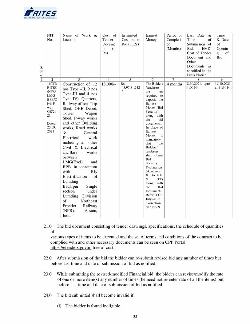
28
S.N
o
NIT No.
Name of Work & Location
Cost of Tender
Docume
nt (in
Rs)
Estimated Cost put to
Bid (in Rs)
Earnest Money
Period of Completi
on
(Months)
Last Date & Time of
Submission of
Bid, EMD,
Cost of Tender
Document and
Other
Documents as
specified in the
Press Notice
Time & Date
of
Openin
g of
Bid
1 2 3 4 5 6 7 8 9
1. 16/OT/RITES
/NFR/LMG-
BPB/C
ivil-P-way-
GE/2021
Dated. 25.09.
2021
Construction of (12
nos Type –II, 9 nos
Type-III and 4 nos
Type-IV) Quarters,
Railway office, Trip
Shed, OHE Depot, Tower Wagon
Shed, P-way works
and other Building
works, Road works
& General
Electrical work including all other
Civil & Electrical
ancillary works
between
LMG(Excl) and
BPB in connection
with Rly
Electrification of
Lumding -
Badarpur Single
section under
Lumding Division
of Northeast
Frontier Railway
(NFR), Assam,
India.”
18,000/- Rs. 43,97,81,242
/-
The Bidders /tenderers
are not required to
deposit the
Earnest Money (Bid
Security) along with
the bid documents. In place of
Earnest
Money, it is
mandatory that the Bidders/
tenderers shall submit
Bid Security
Declaration (Annexure XI to NIT
& ITT) along with
the Bid Documents. Refer GCC
July-2019 Correction
Slip No. 9.
14 months 18.10.2021. upto 11:00 Hrs
19.10.2021.at 11:30 Hrs
21.0 The bid document consisting of tender drawings, specifications, the schedule of quantities
of various types of items to be executed and the set of terms and conditions of the contract to be
complied with and other necessary documents can be seen on CPP Portal https://etenders.gov.in free of cost.
22.0 After submission of the bid the bidder can re-submit revised bid any number of times but
before last time and date of submission of bid as notified.
23.0 While submitting the revised/modified Financial bid, the bidder can revise/modify the rate
of one or more item(s) any number of times (he need not re-enter rate of all the items) but
before last time and date of submission of bid as notified.
24.0 The bid submitted shall become invalid if:
(i) The bidder is found ineligible.

29
(ii) The bidder does not upload all the documents as stipulated in the bid document
including the undertaking about deposition of Bid Security Declaration (Annexure
XI) and Cost of Tender Document uploaded.
(iii) If any discrepancy is noticed between the documents as uploaded at the time of
submission of bid and hard copies as submitted physically by the lowest bidder in the
office of bid opening authority.
(iv) The bidder does not deposit physical instruments of Cost of Tender Document within a week of opening of technical bid.
25.0 Those contractors not registered on the website mentioned above, are required to get
registered beforehand. If needed they can go to CPP Portal https:// eprocure.gov.in/eprocure/app?page=BiddersManualKit&service=page bidders manual
Kit.
26.0 The intending bidder must have valid Class-III digital signature to submit the bid.
27.0 On opening date, the bidder can login and see the bid opening process. After opening of
bids he will be able to view the competitors’ bid documents.
28.0 List of Documents to be scanned and uploaded within the period of bid submission:
-
1. Banker’s Cheque/Pay Order/Demand Draft towards cost of Tender Document in
accordance with Clause 7.0 (f) hereinbefore.
OR Document in support of exemption from payment of cost of Tender Document and
UdyogAadhar Memorandum (UAM) number.
2. The Bidders/tenderers are not required to deposit the Earnest Money (Bid Security) along
with the bid documents. In place of Earnest Money, it is mandatory that the Bidders/
tenderers shall submit Bid Security Declaration (Annexure XI to NIT & ITT) along with the
Bid Documents. Refer GCC July-2019 Correction Slip No. 9.
OR Document in support of exemption from payment of EMD and UdyogAadhar
Memorandum (UAM) number.
3. Authority to Sign (if required as per Clause 11.0 hereinbefore) in the format given at
Annexure III/Annexure IV as applicable.
4. RTGS/NEFT details as per Annexure- VII.
5. Self-attested copy of Documents in support of meeting the criterion of Annual
Financial Turnover in accordance with Para 1 of Annexure I.
6. Self-attested copy of Certificates in support of meeting the criterion of Similar Work
Experience in accordance with Para 2(a) of Annexure I.
7. Details of Similar Works completed in the format given at Performa 1 in Annexure I.
8. Self-attested copy of Certificates in support of meeting the criterion of Construction
Experience in key activities/specified components in accordance with Para 2(b) of
Annexure-I.

30
9. Self-attested copy of Documents (Audited Balance Sheets, Profit & Loss Statements
and Auditor’s Reports) in support of meeting the Profitability criterion in accordance
with Para 4 of Annexure I.
10. Self-attested copy of Documents in support of meeting the criterion of Net Worth in
accordance with Para 5 of Annexure I.
11. Declaration by the Bidder in the format given in Performa 3 of Annexure I.
12. Integrity Pact as per Annexure VI
13. Self-attested copy of Guidelines on Banning of Business Dealings as per Annexure-A.
14. Annexure IX duly filled in.
15. Self-attested copy of a certificate, confirming that the applicant is working contractor
or has executed any work within the last seven years reckoned from the date of
opening of tender, issued by Railways, CPWD, MES, DOT, RITES, State PWD or
any other Central/State Government Undertaking, Municipal Body of Central/State
Government or Public Limited Company listed in Stock Exchange in India &
Abroad.
16. Self-Attested Copy of Partnership Deed/Memorandum and Articles of Association of
the firm.
17. Self-Attested copy of Corrigendum(s), if any.
18. Self-attested copy of any other document if specified in the correction slips to the
Tender Document.
19. Self-certified copy of the Joint Venture Agreement/Memorandum of Understanding as per Annexure II & Annexure IV (where Joint Venture is allowed).
20. Power of Attorney in favour of Lead Member as the Lead Member of JV executed by
the authorized representatives of all the members of JV (where Joint Venture is
allowed).
21. Self-attested copy of a certificate, confirming that the Partners including Lead
Partner duly signed by the Authorized representative of each Partner/Member of
Joint Venture is a working contractor or has executed any work within the last seven
years reckoned from the date of opening of Tender, issued by Railways, CPWD,
MES, DOT, RITES, State PWD or any other Central/State Government Undertaking,
Municipal Body, Autonomous Body of Central or State Government or Public
Limited Company listed on NSE/BSE (where Joint Venture is allowed)
22. Self-attested copy of GST Registration Certificate (As applicable).
Note: - Any clarification / deficient document(s) sought by RITES Ltd. as per Clause
shall be submitted by the bidder online only.
29.0 List of Documents to be submitted physically by Lowest (L1) Bidder within a week
of the Opening of Financial Bid: -

31
1. Self-attested copy of PAN/TAN issued by income Tax Department.
2. Self-attested copy of registration under Labour Laws like PF, ESI etc.
3. Self-attested copy of ISO 9000 Certificate. (if any)
4. Self-attested copies of all the documents specified in Clause 28.0 above.
30.0 RITES Ltd. may approach any Bank, Individual, Employer, Firm or Corporation, whether mentioned in the documents submitted by bidders or not, to verify the credentials and
general reputation of the bidder and where JV is allowed the credentials and general reputation of lead member & each Member of Joint Venture.
31.0 With reference to Clause 3, Sub-clause 3(a) , 3(a) (i), 3(b) and Clause 52.7 of Clauses of
Contract of RITES GCC for works (Section-8) , the name of the contractor declared as “Poor Performer” as per 52.7 and the contractor, whose Contract is determined as per
clause 3 and deemed to be declared as “Poor Performer” as per Sub-clause 3(a)(i) will be
placed in RITES “Negative List of Contractors” and then such a contractor individually
and also any Joint Venture wherein such contractor is a member, will not be eligible for a
period of up to two years , to participate in tenders of other works and in the tendering
process for balance works as per sub-clause 3(b) which may be invited by RITES. In case
the contractor is a Joint Venture, the JV as well as all members of the JV individually or
as member(s) of any other Joint Venture (JV) will not be so eligible. In case the
contractor is a company then, in addition to the aforesaid provisions, the Associate
Companies and Subsidiary Companies (as defined under Companies Act, 2013), of the
company included in the Negative List, will also not be eligible.

32
ANNEXURE – I
QUALIFYING CRITERIA FOR WORKS CONTRACTS
1. ANNUAL FINANCIAL TURNOVER- APPLICABLE
The bidder should have achieved a minimum annual financial turnover of Rs. 18,84,77,675/-
in any one of the last 3 Financial Years.
Notes:
a) The financial turnover will be taken as given under the head “Income” in audited Profit and Loss
Account and excluding non-recurring income, income from other sources and stock. It is clarified that the Financial Turnover means relevant revenue as recorded in the Income side of
Profit and Loss Account. It does not mean Profit.
b) Closing stocks in whatsoever manner should not form part of turnover.
c) Weightage of 7% (compounded annually) shall be given for equating the financial turnover of
the previous years to the current year.
d) For considering the Financial Years, for example for a work for which the last stipulated date for
submission of the bids is in Financial Year 2014-15, the last three Financial Years will be 2013-
14, 2012-13 and 2011-12. For a work for which the last stipulated date for submission of the bids
is on (say) 05.09.14 (F.Y. 2014-15), with weightage of 7% compounded annually, the
weightages to be applied on the Turnover of the previous three Financial Years will be: F.Y.
2013-14 = 1.070; F.Y. 2012-13 = 1.145; F.Y. 2011-12 = 1.225
e) The Bidder should furnish Annual Financial Turnover for each of the last 3 Financial Years in tabular form and give reference of the document (with page no.) relied upon in support of
meeting the Qualification Criterion.
f) The Bidder should submit self-attested copy of Auditor’s Report along with Balance Sheet and Profit and Loss Statement along with Schedules for the relevant Financial Year in which the
minimum criterion is met. Provisional Audit Reports or certified statements will not be accepted.
g) If the Audited Balance Sheet for the immediately preceding year is not available in case of work
for which the last stipulated date for submission of the bids is before 30th September audited
Balance Sheets, Profit and Loss Statements and other financial statements of the three Financial
Years immediately preceding the previous Financial Year may be adopted for evaluating the
credentials of the Bidder.
h) In case JV is permitted the following provisions will apply: -
i) Normal Works
The Partner-in-charge/Lead Member shall singly meet this criterion.

33
2. WORK EXPERIENCE
For Works in Difficult Areas
The Bidder should have satisfactorily completed in his own name or proportionate share as a
member of a Joint Venture, at least one similar work of minimum value of Rs. 17,59,12,497/-
OR at least two similar works each of minimum value of Rs 10,99,45,310/- during the last 7
(seven) years prior to the last stipulated date for submission of the Bid. Works completed prior to the cut-off date shall not be considered.
Similar Works
Similar Works shall mean “Any Civil Engineering work involving construction of residential/service Buildings for Railways, CPWD, MES, DOT, RITES, State PWD or any other Central/State Government Department, Central/State Government Undertaking or their subsidiaries, Municipal Body, Autonomous Body of Central / State Governments or Public Ltd., carried out in India” under a single contract (including additional work carried out under the contract).”
“Similar nature of works”. The works other than those specified above will not be
considered in term “Similar nature of works”
In case the Bidder (Indian Company) wishes to rely on a work completed abroad, the value of
such completed work in foreign convertible currency shall be converted into Indian Rupees. The
conversion rate shall be decided by RITES based on the rates of currency on the date of
completion of work (the bidder to also submit the currency conversion rate as on completion date
of the Credential Certificate relied upon by the bidder for the purpose of work experience).
Further, such a bidder (Indian Company) should have also completed at least one similar work of
value minimum 25% of estimated cost of work, in India in the last Seven years prior to the last
stipulated date for submission of the Bids
(strike out (a) or (aa) as applicable)
Notes:
I. A weightage of 7% (compounded annually from the date of completion of the work to the last stipulated date for submission of the Bids) shall be given for equating the value of works to the
last stipulated date for submission of the Bids. For example, for a similar work of Rs. 1,00,000/- completed on 31.12.2017 and the last stipulated date for submission of the bids was 31.08.2020,
the value of work shall be considered after giving weightage is (Rs. 1,00,000 * 1.07*1.07) { 1+[(7/100)*(244/366)]} = Rs. 119832.87, rounded off to Rs. 119833/-
II. Only such works shall be considered where physical completion of entire work is over or
commissioning of work has been done, whichever is earlier.
III. The Bidder should submit the details of such similar completed works as per the format at
Proforma-1 enclosed.
IV. Works carried out by another Contractor on behalf of the Bidder on a back to back basis will not
be considered for satisfaction of the Qualification Criterion by the Bidder.
V. Credential certificates issued by Government Organizations/Semi Government Organizations
of Central or State Government; or by Public Sector Undertakings/ Autonomous Bodies of
Central/State Government or their subsidiaries/by Public Ltd. Companies listed in Stock

34
exchange in India or Abroad or subsidiaries of such companies shall only be accepted for
assessing the eligibility of a Tenderer. Certificates issued by one of the aforesaid organizations as
a lead member (having equity stake of 51% or more) of a Joint Venture (JV) for a work executed
for the JV, will also be acceptable. In case of PPP projects, if the bidder has executed a work for
a concessionaire who is one of the aforesaid organizations, then the certificate issued by such
concessionaire or by the public authority concerned, will also be acceptable.
VI. The cutoff date shall be calculated backwards from the last stipulated date for submission of
Tender i.e. for a Tender having the last stipulated date for submission on 06.08.2014, the cutoff date shall be 07.08.2009.
VII. In case JV is permitted the following provisions will apply:
Large Works
All the partners shall jointly meet this criterion.
Normal Works
The Partner-in-charge/Lead Member shall singly meet this criterion.
a) Construction Experience in Key Activities/Specified Components - APPLICABLE
S.No. Nature of Work Required Criteria
1 General
Electrification
Must have valid electrical Contractor license from appropriate
Govt. Authority
If one or more Subcontractor is deployed for Electrical General Work then such subcontractors for above General Electrical works shall require prior approval of RITES
before start of work.
Notes:
I. Credential certificates issued by Government Organizations/Semi Government
Organizations of Central or State Government; or by Public Sector Undertakings/
Autonomous Bodies of Central/State Government or their subsidiaries/by Public Ltd.
Companies listed in Stock exchange in India or Abroad or subsidiaries of such companies
shall only be accepted for assessing the eligibility of a Tenderer. Certificates issued by
one of the aforesaid organizations as a lead member (having equity stake of 51% or
more) of a Joint Venture (JV) for a work executed for the JV, will also be acceptable. In
case of PPP projects, if the bidder has executed a work for a concessionaire who is one of
the aforesaid organizations, then the certificate issued by such concessionaire or by the
public authority concerned, will also be acceptable.
II. When key activities/specified components are expressed/ specified in monetary terms, a
weightage of 7% (compounded annually from the date of completion of the key activity to the last stipulated date for submission of the Bids). For example, for a key activity of
Rs. 1,00,000/- completed on 31.12.2017 and the last stipulated date for submission of the bids was 31.08.2020, the value of key activity that shall be considered after giving
weightage is (Rs.1,00,000*1.07*1.07){1+[(7/100)*(244/366)]} = Rs. 119832.87, rounded off to Rs. 119833/-
III. The work satisfying the criterion for a particular key activity may be different from a work satisfying the criterion for another key activity.

35
IV. The Bidder should furnish with his Bid a tabular statement giving contract-wise
quantities/amount of key activities (mentioning date of start and date of completion of
key activities) executed in the last 7 years prior to the last stipulated date for submission
of the bids which meet the Qualification Criterion along with documentary proof in
support thereof (indicating page nos.).
V. Even if a work has not been completed but if the specified quantity / specified value in
monetary terms of the key activity has been completed, the same shall be taken into consideration for the purpose of this criterion.
VI. Any work executed by the Bidder as a member of a Joint Venture will be accepted
provided there is documentary proof in support of the same either in the MOU/Agreement of the JV or in a declaration by the other Members of that JV or the
Client confirming that the key activity was actually executed by the Bidder.
In case JV is permitted the following provisions will apply:
Large Works.
All the partners shall jointly meet this criterion.
Normal Works
All the partners shall jointly meet this criterion.
3. SERVICING OF LOAN / CREDIT LIMIT
(i) The bidder should furnish a declaration that he has not failed to service the principal amount or interest or both of a loan amount / credit limit from any Bank or Financial
Institution during a period of one year prior to the deadline for submission of bids the last stipulated date for submission of bids.
Notes:
a) In case a bidder has defaulted in servicing his loan/credit limit during past one year,
he shall be disqualified.
b) The declaration may be included in the Declaration to be submitted in Performa 3
tothis Annexure.
c) In case JV is permitted the following provisions will apply:
Large Works
Each partner shall sign the declaration.
Normal Works
The Partner-in-charge/Lead Member shall sign the declaration.
4. PROFITABILITY: APPLICABLE

36
The Bidder should be a profit (net) making firm and should have made profit during any
two of the past 3 Financial Years immediately preceding the last stipulated date for
submission of bids. If the audited Balance Sheet for the immediately preceding year is
not available in case of the work for which the last stipulated date for submission of the
bids is before 30th September, Audited Balance Sheets of the three financial Years
immediately preceding the previous Financial Year shall be considered.
The Bidder should furnish figures of net profit of last 3 years in a tabular form and submit attested copies of Auditor’s Reports along with audited Balance Sheets and Profit
and Loss Statements for the last three Financial Years. Specific reference with page no. of document which proves satisfaction of this Qualifying Criterion should be indicated
in the tabular statement.
Notes:
- In case JV is permitted, the following provisions will apply: Large Works
All the partners shall meet individually this criterion.
Normal Works
The Partner-in-charge/Lead Member shall singly meet this criterion.
5. NET WORTH: APPLICABLE
The Bidder should have positive Net Worth of at least Rs. 6,59,67,186/- (15% of the
estimated cost)
Notes:
a) Net Worth shall be computed from the bidder’s audited balance sheet of the
lastfinancial year ending on a date not prior to 18 months from the due date ofsubmission of the tender (or, if the date is extended, such extended date of
submission).
b) In case JV is permitted, the following provisions will apply:
Large Works
All the partners shall jointly meet this criterion.
Normal Works
The Partner-in-charge/Lead Member shall singly meet this criterion
6. POINTS TO NOTE ON SATISFACTION OF QUALIFYING CRITERIA IN CASE
OF BOTH LARGE AND NORMAL WORKS
a) Sub-Contractor’s Experiences and Resources
Sub-Contractors’ Experiences and Resources will not be taken into account in
determining the Bidder’s compliance with the qualifying criteria.
37
b) Experiences and Resources of the Parent Company and other subsidiary
companies
If the Bidder is a wholly owned subsidiary of a company, the experience and
resources of the owner/parent company or its other subsidiaries will not be taken
into account. However, if the Bidder is a Company, only the Experience (and not
the Financial Resources) of its subsidiaries will be taken into consideration.
7. DISQUALIFICATION ON CERTAIN GROUNDS
Even though the Bidders may meet the above qualifying criteria, they are subject to be
disqualified if they have
a) Concealed any information/document which may result in the Bidder’s disqualification or if any statement/information/document furnished by the Bidder
or issued by a Bank/Agency/Third party and submitted by the Bidder, is
subsequently found to be false or fraudulent or repudiated by the said
Bank/Agency/Third Party. In such a case, besides Bidder’s liability to action under
para 9.4 of Instructions to Tenderers, the Bidder is liable to face the penalty of
banning of business dealings with him by RITES.
b) Records of any contract awarded to them, having been determined during the past
three years prior to the dead line for submission of bids.
c) Been declared as Poor Performer by RITES and their name is currently in the
‘Negative List’ of RITES.
d) Their business banned or suspended by any Central/State Government Department/ Public Undertaking or Enterprise of Central/State Government and
such ban is in force.
e) Not submitted all the supporting documents or not furnished the relevant details as per the prescribed format.
A declaration to the above effect in the form of affidavit on stamp paper of Rs.
10/-duly attested by Notary/Magistrate should be submitted as per format given in
Proforma 3 enclosed.
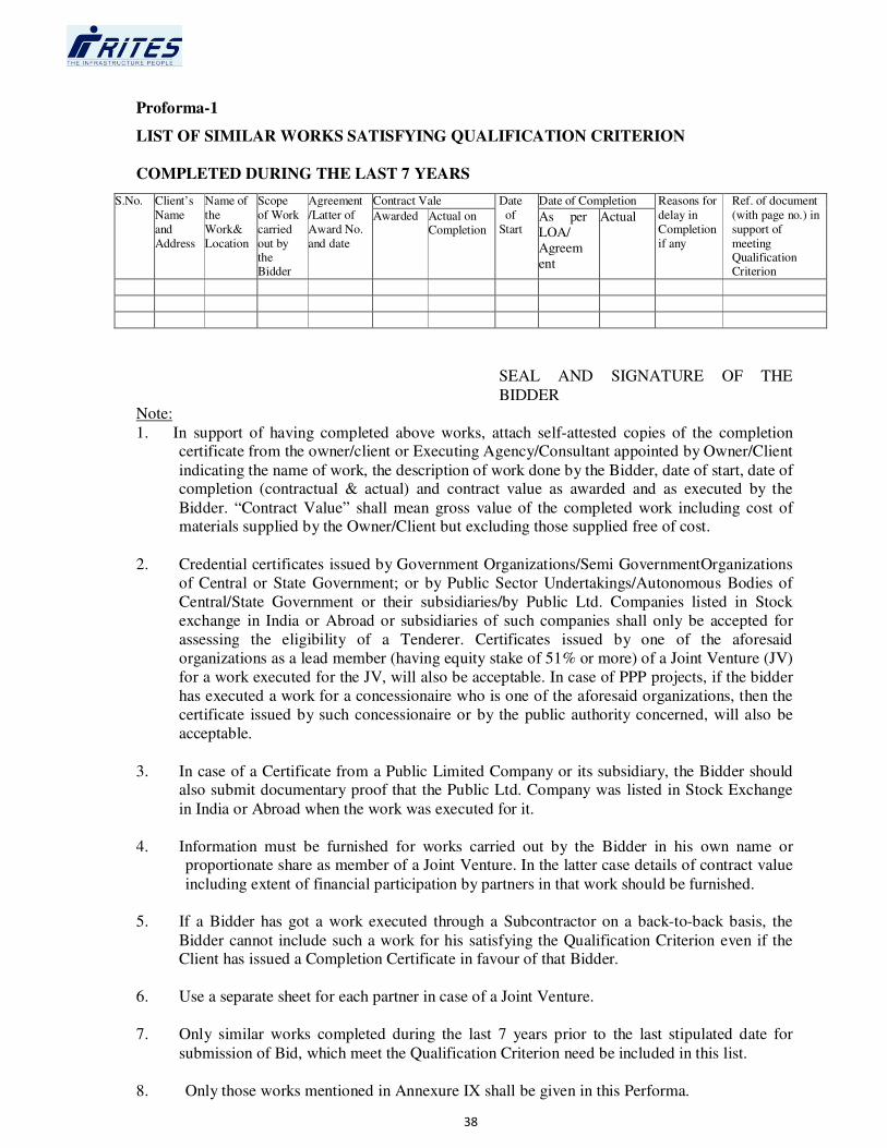
38
Proforma-1
LIST OF SIMILAR WORKS SATISFYING QUALIFICATION CRITERION
COMPLETED DURING THE LAST 7 YEARS
S.No. Client’s
Name
and
Address
Name of
the
Work&
Location
Scope
of Work
carried
out by the Bidder
Agreement
/Latter of
Award No.
and date
Contract Vale Date
of
Start
Date of Completion Reasons for
delay in
Completion
if any
Ref. of document
(with page no.) in
support of
meeting Qualification Criterion
Awarded Actual on Completion
As per
LOA/
Agreem
ent
Actual
SEAL AND SIGNATURE OF THE
BIDDER Note:
1. In support of having completed above works, attach self-attested copies of the completion certificate from the owner/client or Executing Agency/Consultant appointed by Owner/Client
indicating the name of work, the description of work done by the Bidder, date of start, date of completion (contractual & actual) and contract value as awarded and as executed by the
Bidder. “Contract Value” shall mean gross value of the completed work including cost of materials supplied by the Owner/Client but excluding those supplied free of cost.
2. Credential certificates issued by Government Organizations/Semi GovernmentOrganizations
of Central or State Government; or by Public Sector Undertakings/Autonomous Bodies of
Central/State Government or their subsidiaries/by Public Ltd. Companies listed in Stock
exchange in India or Abroad or subsidiaries of such companies shall only be accepted for
assessing the eligibility of a Tenderer. Certificates issued by one of the aforesaid
organizations as a lead member (having equity stake of 51% or more) of a Joint Venture (JV)
for a work executed for the JV, will also be acceptable. In case of PPP projects, if the bidder
has executed a work for a concessionaire who is one of the aforesaid organizations, then the
certificate issued by such concessionaire or by the public authority concerned, will also be
acceptable.
3. In case of a Certificate from a Public Limited Company or its subsidiary, the Bidder should also submit documentary proof that the Public Ltd. Company was listed in Stock Exchange
in India or Abroad when the work was executed for it.
4. Information must be furnished for works carried out by the Bidder in his own name or proportionate share as member of a Joint Venture. In the latter case details of contract value
including extent of financial participation by partners in that work should be furnished.
5. If a Bidder has got a work executed through a Subcontractor on a back-to-back basis, the
Bidder cannot include such a work for his satisfying the Qualification Criterion even if the Client has issued a Completion Certificate in favour of that Bidder.
6. Use a separate sheet for each partner in case of a Joint Venture.
7. Only similar works completed during the last 7 years prior to the last stipulated date for
submission of Bid, which meet the Qualification Criterion need be included in this list.
8. Only those works mentioned in Annexure IX shall be given in this Performa.

39
Proforma 2
Solvency Certificate from a Nationalized or a Scheduled Bank
-Deleted-
40
Performa 3
DECLARATION BY THE BIDDER
(Affidavit on Non-Judicial Stamp Paper of Rs.10/- duly attested by Notary/Magistrate)
This is to certify that We, M/s……………………………… in submission of this offerconfirm
that: -
i) We have visited the site of work and seen the working conditions, approach road/path, availability of water, electricity, construction labour, construction materials and other
relevant requirements connected with the work.
ii) We have neither concealed any information/document which may result in our
disqualification nor made any misleading or false representation in the forms, statements
and attachments in proof of the qualification requirements;
iii) During the past three years prior to the deadline for submission of bids, no contract
awarded to us has been determined.
iv) No Central/State Government Department/Public Sector Undertaking or Enterprise of
Central/State Government has banned/suspended business dealings with us as on date.
v) We have submitted all the supporting documents and furnished the relevant details as per
prescribed format and we agree to submit, without delay additional information/documents
which may be demanded by RITES Ltd.
vi) List of Similar Works satisfying Qualification Criterion indicated in Proforma 1 does not include any work which has been carried out by us through a Subcontractor on a back to
back basis.
vii) The information and documents submitted with the Tender and those to be submitted subsequently by way of clarifications are correct and we are fully responsible for the
correctness of the information and documents submitted by us.
viii) We have not failed to service the principal amount or interest or both of a loan
account/credit limit from any Bank or Financial Institution during a period of one year
prior to the deadline for submission of bids.
ix) *The original instruments of EMD (The Bidder is required to submit Bid Security
Declaration (Annexure XI to NIT & ITT) Refer GCC July-2019 Correction Slip No.
9) and Cost of Tender Document, in physical form shall be deposited by us with RITES
Ltd. within a week from the date of opening of Technical Bid failing which RITES Ltd.
may reject the bid and also take action to debar us from participating in Tenders invited by
RITES Ltd. for a period of two years.
OR
*We are exempted from payment of cost of Tender Document and EMD and the certified
copies of original documents in support of such exemption shall be deposited by us with RITES Ltd. within a week from the date of opening of Technical Bids and original
documents produced on demand, failing which RITES Ltd. may reject the bid and also

41
take action to debar us from participating in Tenders invited by RITES Ltd. for a period of
two years.
(* Delete whichever is not applicable)
x) We understand that in case any information/document which may result in our
disqualification is concealed by us or any statement/information/document furnished by us or to be furnished by us in connection with this offer, or issued by Bank/Agency/Third
Party is subsequently found to be false or fraudulent or repudiated by the said Bank/Agency/Third Party, business dealings with us may be banned.
SEAL, SIGNATURE & NAME OF THE BIDDER
Signing this document
42
ANNEXURE II
DRAFT MEMORANDUM OF UNDERSTANDING EXECUTED BY MEMBERS OF
THE JOINT VENTURE
(On each firm’s Letter Head)
From
……………………… ………………………
To
RITES Ltd.
………………………
Dear Sir,
Re: RITES Tender Notice No………………….. dated ………….. for
……………………………………… (Name of Work)
We wish to conform that our company/firm (delete as appropriate) has formed a Joint Venture with
………………………………………. (insert names of all other members of the group)
for purposes associated with your Tender No ..............................................................................
(Members who are not the Lead Member of the Joint Venture should add the following paragraph)
* * The Joint Venture is led by ………………………………. (insert name of the Lead Member)
whom we hereby authorize to act as leader on our behalf for the purposes of submission of Bid for ………………………. (name of work) and to incur liabilities and receive instructions for and on
behalf of any and all the partners of the Joint Venture. For this purpose, we have executed a Power
of Attorney in favour of ……………………………. (name of the Lead Member)
(Member who is the Lead Member of the Joint Venture should add the following paragraph) **
** In this Joint Venture we act as Lead Member and for the purposes of bidding for the work,
represent the Joint Venture.
Till the award of work, the Lead Partner shall furnish Bid bond and all other bonds/guarantees to
the Employer on behalf of the Joint Venture, which shall be legally binding on all the partners of
the Joint Venture.
In the event of our Joint Venture being awarded the contract we agree to be jointly with
…………………………… (insert names of all other members of the Joint Venture) and
severally liable to RITES, its successors and assigns for all obligations, liabilities, duties and responsibilities arising from or imposed by the contract subsequently entered into between RITES
and our Joint Venture.

43
The precise responsibility of the Lead Member and other Members of the Joint Venture in respect
of planning, design, construction equipment, key personnel, work execution andfinancing of the
Work including Percentage of financial participation by each Member will be as indicated in the
Annexure. These shall not be varied/ modified subsequently without your prior approval.
We further agree that entire execution of the contract shall be carried out exclusively through the
Lead Member.
In case our Bid is successful, the Joint Venture Agreement incorporating the above provisions will be executed within 15 days of receipt of Letter of Acceptance from you and shall be registered at
the place where the Agreement will be signed, so as to be legally valid and binding on all Members of the Joint Venture.
We agree that the Joint Venture Agreement shall be valid during the entire currency of the Contract
including the period of extension if any, and the maintenance period after the work is completed.
We further confirm that we shall open a Bank Account in the name of JV and all payments due to
the JV shall be made by you by crediting to that Account. To facilitate statutory deductions such as
towards Income Tax and VAT made from the amounts due to us against our bills, being credited to
the concerned Government departments, we shall obtain PAN/TIN number etc. as required and
advise you the details before claiming our first on-account bill.
We affirm that the Integrity Pact with the Employer in the format at Annexure VI (if applicable)
shall be signed by the Lead Member duly witnessed, on behalf of the Joint Venture. All Members
including the Lead Member shall comply with the provision in the Integrity Pact and any violation
of the Integrity Pact by any Member shall be construed as violation by the Joint Venture.
Encl: Annexure.
Yours faithfully,
Signature ………………………….……….
(Name of Signatory) …………….……….…
(Capacity of Signatory) …………………….
Seal
Witness 1 Witness 2
Name Name
Address Address
Occupation Occupation
Not
e:
1. To be executed by each Member of the Joint Venture individually.

44
ANNEXURE III
FORMAT FOR POWER OF ATTORNEY TO AUTHORISED SIGNATORY
POWER OF ATTORNEY
(To be executed on non-judicial stamp paper of the appropriate value in accordance with relevant
Stamp Act. The stamp paper to be in the name of the firm/company who is issuing the Power of
Attorney)
We, M/s………………………………………. (name of the firm/company with address of
the registered office) hereby constitute, appoint and authorize Mr./Ms.……………………….
(Name and residential address) who is presently employed with us and holding the position of
…………………………. and whose signature is given below as our Attorney to do in our
name and our behalf all or any of the acts, deeds or things necessary or incidental to our bid for
the work “Construction of (12 nos Type –II , 9 nos Type-III and 4 nos Type-IV) Quarters,
Railway office, Trip Shed ,OHE depot , Tower Wagon Shed , P-way works , other Building
works , road works including all ancillary works between LMG(Excl) and BPB Single Line
under Lumding Division of under Northeast Frontier Railway(NFR),Assam, India.”including
signing and submission of application/proposal, participating in the meetings, responding to
queries, submission of information/documents and generally to represent us in all the dealings
with RITES or any other Government Agency or any person, in connection with the works until
culmination of the process of bidding, till the Contract Agreement is entered into with RITES and
thereafter till the expiry of the Contract Agreement.
We hereby agree to ratify all acts, deeds and things lawfully done by our said Attorney pursuant to
this Power of Attorney and that all acts, deeds and things done by our aforesaid Attorney shall always be deemed to have been done by us.
(Add in the case of a Joint Venture)
Our firm is a Member/Lead Member of the Joint Venture of ………………………,
……………. and ………………
Dated this the ……………… day of ………………… 20…….
……………………………………………..
(Signature and name of authorized signatory being given Power of Attorney)
……………………………………………..
(Signature and name in block letters of *All the partners of the firm, *Authorized Signatory for
the Company)
(*Strike out whichever is not applicable)
Seal of firm/ Company

45
Name:
Address:
Occupation:
Notes:
- In case the Firm/Company is a Member of a Joint Venture, the authorized signatory has to be the one employed by the Lead Member.
- The mode of execution of the Power of Attorney should be in accordance with the procedure, if
any, laid down by the applicable law and the charter documents of the executants (s) and when it
is so required the same should be under common seal affixed in accordance with the required
procedure.

46
ANNEXURE IV
FORMAT FOR POWER OF ATTORNEY TO LEAD MEMBER OF JOINTVENTURE:
(To be executed on non-judicial stamp paper of the appropriate value in accordance with relevant Stamp Act. The stamp paper to be in the name of the company who is issuing the Power of
Attorney)
Whereas ………………. RITES Ltd. has invited bids for ………………. (Name of work) for
and on behalf of ………………. as an Agent /Power of Attorney Holder.
Whereas, the Members of the Joint Venture (JV) comprising of M/s………….,
M/s……………, M/s…………. and M/s …………. (the respective names and addresses of the
registered offices to be given) are interested in bidding for the work and implementing the same in
accordance with the terms and conditions contained in the bid documents.
Whereas, it is necessary for the members of the JV to designate one of them as the Lead Member
with all necessary power and authority to do, for and on behalf of the JV, all acts, deeds and things as may be necessary in connection with the JV’s bid for the work.
NOW THIS POWER OF ATTORNEY WITNESSETH THAT
We, M/s …………., M/s …………. and M/s ……………. hereby designate M/s. ……… being
one of the members of the JV, as the Lead Member of the JV, to do on behalf of the JV, all or any
of the acts, deeds or things necessary or incidental to the JV’s bid for the work, including submission of application proposal, participating in meetings, responding to queries, submission of
information/documents and generally to represent the JV in all its dealings with RITES or any other
Government Agency or any person, in connection with the work until culmination of the process of
bidding till the contract agreement is entered into with RITES and thereafter till the expiry of the
contract agreement.
We hereby agree to ratify all acts, deeds and things lawfully done by our said Attorney pursuant to
this Power of Attorney and that all acts, deeds and things done by our aforesaid Attorney shall and
shall always be deemed to have been done by us/JV.
Dated this the …………. day of …………. 20
……………………………….
(Signature and Name in Block letters of *All the Partners of the firm / * Authorized Signatory for
the Company)
………………………………..
(* Strike out whichever is not applicable)
Seal of firm / Company
47
Name:
Address:
Occupation:
Notes: - To be executed by all the members individually, in case of a JV.
- The mode of execution of the Power of Attorney should be in accordance with the
procedure, if any laid down by the applicable law and the charter documents of the executant (s) and when it is so required the same should be under common seal affixed in
accordance with the required procedure.

48
ANNEXURE V
FORM OF AGREEMENT
(ON NON-JUDICIAL STAMP PAPER OF APPROPRIATE VALUE)
Agreement No. ……………………………… dated ………………….
THIS AGREEMENT is made on ………… day of …………………… Two thousand
………………. between RITES Ltd. a Government of India Enterprise and a Company
registered under Companies Act, 1956 having its registered office at SCOPE Minar, Laxmi Nagar,
Delhi-110092 and its Corporate Office at RITES BHAWAN, Plot No.1, Sector 29, Gurgaon
(Haryana) representing through ………………………………, RITES LIMITED
acting for and on behalf of and as an Agent /Power of Attorney Holder of “……………”hereinafter
called the Employer (which expression shall, wherever the context so demands or requires, include
their successors in office and assigns) on one part and M/s……………………hereinafter called the
Contractor (which expression shall wherever the context so demands or requires, include his/ their
successors and assigns) of the other part.
WHEREAS the Employer is desirous that certain works should be executed
viz.……………………………………….. (brief description of work) and has by Letter of
Acceptance
dated ……………………accepted a tender submitted by the Contractor for the execution,completion, remedying of any defects therein and maintenance of such works at a total
Contract Price of Rs. …………………. (Rupees ………………………… only)
NOW THIS AGREEMENT WITNESSETH as follows: -
1. In this Agreement words and expressions shall have the same meaning as are respectively
assigned to them in the Conditions of Contract hereinafter referred to.
2. The following documents in conjunction with addenda/corrigenda to Tender Documents shall be
deemed to form and be read and construed as part of this agreement viz.
The Letter of Acceptance dated …………………….
Priced Schedule (Bill) of Quantities
Notice Inviting Tender and Instructions to Tenderers. RITES Tender and Contract Form
[DELETED]
Special Conditions
Schedules A to F Technical Specifications Drawings
Amendments to Tender Documents (List enclosed)
General Conditions of Contract (read with Correction Slip Nos. 1 to --) comprising of
(i) Conditions of Contract

49
(ii) Clauses of Contract
(iii) RITES Safety Code
(iv) RITES – ModelRules for the protection of Health and Sanitary arrangements for Workers
(v) RITES – Contractor’s Labour Regulations
3. In consideration of the payment to be made by the Employer to the Contractor as hereinafter
mentioned, the Contractor hereby covenants with the Employer to execute, complete, remedy defects therein and maintain the works in conformity in all respects with the provisions of the
Contract.
4. The Employer hereby covenants to pay to the Contractor in consideration of the execution,
completion, remedying of any defects therein and maintenance of the works, the contract price or
such other sum as may become payable under the provisions of the contract at the time and in the
manner prescribed by the Contract.
IN WITNESS whereof the parties hereto have caused their respective common seals to be hereinto
affixed (or have herewith set their respective hands and seals) the day and year first above written.
SIGNED, SEALED AND DELIVERED BY
…………………………………………. ………………………………………….
In the capacity of ……………………… Representing RITES LIMITED In the capacity of Agent/Power of Attorney
Holder
On behalf of M/s ……………………… For and on behalf of ………………………
(The Contractor) (The Employer)
In the presence of In the presence of
Witness (Signature, Name & Designation) Witness (Signature, Name & Designation)
1. 1.
2. 2.
50
ANNEXURE VI
`
INTEGRITY PACT
Between RITES LTD. acting for and on behalf of and as an Agent / Power of Attorney Holder of____________ hereinafter called the “Employer” AND ____________ hereinafter referred to as "The Bidder/Contractor" Preamble
The Employer intends to award, under laid down organizational procedures, contract/s for
______________. The Employer values full compliance with all relevant laws and regulations, and
economic use of resources, and of fairness and transparency in his relations with the Bidder/s
and/or contractor/s.
In order to achieve these goals, the Employer will appoint an Independent External Monitor (IEM)
who will monitor the Tender process and execution of the contract for compliance with the principles
mentioned above.
Section 1 – Commitments of the Employer
1 The Employer commits himself to take all measures necessary to prevent corruption and to observe the following principles:-
4. No employee of the Employer, personally or through family members, will in connection with the
tender or for the execution of the contract, demand, take a promise for or accept, for self or third person, any material or immaterial benefit which the person is not legally entitled to.
5. The Employer will, during the tender process, treat all Bidders with equity and reason. The Employer will in particular, before and during the tender process, provide to all Bidders the same information and will not provide to any Bidder confidential/additional information through which the Bidder could obtain an advantage in relation to the tender process or the contract execution.
6. The Employer will exclude from the process all known prejudiced persons.
a) If the Employer obtains information on the conduct of any of his employees which is a criminal offence under the IPC (Indian Penal Code) /PC (Prevention of Corruption) Act, or if there be a substantive suspicion in this regard, the Employer will inform its Chief Vigilance Officer and in addition can initiate disciplinary action.
Section 2 – Commitments of the Bidder/Contractor
11. The Bidder/Contractor commits himself to take all measures necessary to prevent corruption. He
commits himself to observe the following principles during his participation in the tender process
and during the contract execution.
1. The Bidder/Contractor will not directly or through any other person or firm, offer, promise or give to any of the Employer’s employees involved in the tender process or the execution of the contract or
to any third person any material or other benefit which he is not legally entitled to, in order to obtain
in exchange any advantage of any kind whatsoever during the tender process or during the
execution of the contract.

51
2. The Bidder/Contractor will not enter with other Bidders into any undisclosed agreement or
understanding, whether formal or informal. This applies in particular to prices, specifications,
certifications, subsidiary contracts, submission or non-submission of bids or any other actions, to
restrict competitiveness or to introduce cartelization in the bidding process.
3. The Bidder/Contractor will not commit any offence under the relevant IPC/PC Act; further the
Bidder/ Contractor will not use improperly, for purposes of competition or personal gain, or pass on
to others, any information or document provided by the Employer as part of the business
relationship, regarding plans, technical proposals and business details, including information
contained or transmitted electronically.
4. The Bidder/Contractor will, when presenting his bid, disclose any and all payments he has made, is
committed to or intends to make to agents, brokers or any other intermediaries in connection with
the award of the contract.
5. Foreign bidders shall disclose the name and address of agents and representatives in India.
6. Indian Bidders shall disclose their foreign principals or associates.
(2) The Bidder/ Contractor will not instigate third persons to commit offences outlined above or be an
accessory to such offences.
Section 3- Disqualification from tender process and exclusion from future contracts
If the Bidder/Contractor, before award or during execution has committed a transgression through a
violation of Section 2 above, or in any other form such as to put his reliability or credibility in
question, the Employer is entitled to disqualify the Bidder/Contractor from the tender process or
take action as per the procedure mentioned in the "Guideline on banning of business dealing"
annexed and marked as Annexure "A".
Section 4- Compensation for Damages
(1) If the Employer has disqualified in terms of the provisions in Section 3, the Bidder/Contractor from the tender process prior to the award of contract, the Employer is entitled to demand and recover the damages equivalent to Earnest Money Deposit/ Bid Security.
(2) If the Employer has terminated the contract during execution in terms of the provisions under Section 3, the Employer shall be entitled to demand and recover from the Contractor the damages equivalent to Earnest Money Deposit, Security Deposits already recovered and Performance Guarantee, which shall be absolutely at the disposal of the Employer.
Section -5 Previous transgression
(1) The Bidder/ Contractor declares that no previous transgression occurred in the last 3 years with any other Company in any country conforming to the Anti-Corruption approach or with any other Public Sector Enterprise in India that could justify his exclusion from the tender process.
(2) If the Bidder/Contractor makes incorrect statement on this subject, he can be disqualified from the tender process or action can be taken as per the procedure mentioned in "Guideline on banning of business dealing".
Section -6 Equal treatment of all Bidders/Contractors/Sub-Contractors
(1) The Bidder/Contractor undertakes to demand from all partners/sub-contractors (if permitted under
the conditions/ clauses of the contract) a commitment to act in conformity with this Integrity Pact
and to submit it to the Employer before signing the contract.

52
(2) The Bidder/ Contractor confirms that any violation by any of his partners/sub-contractors to act in conformity with the provisions of this Integrity Pact can be construed as a violation by the Bidder/Contractor himself, leading to possible Termination of Contract in terms of Section 4.
(3) The Employer will disqualify from the tender process all bidders who do not sign this Pact or violate its provisions.
Section 7- Criminal charges against violating Bidders/Contractors/Sub- Contractors
If the Employer obtains knowledge of conduct of a Bidder, Contractor or Partners/Sub Contractor, or of an employee or a representative or an associate of a Bidder, Contractor or Sub Contractor, which constitutes corruption, or if the Employer has substantive suspicion in this regard, the Employer will inform the same to its Chief Vigilance Officer.
Section -8 Independent External Monitor/Monitors
(1) The Employer shall appoint competent and credible Independent External Monitor for this Pact. The task of the Monitor is to review independently and objectively, whether and to what extent the parties comply with the obligations under this agreement.
(2) The Monitor is not subject to instructions by the representatives of the parties and will perform his functions neutrally and independently. He will report to the CMD/RITES Ltd.
(3) The Bidder/Contractor accepts that the Monitor has the right of access without restriction to all Project documentation of the Employer including that provided by the Contractor. The Contractor will also grant the Monitor, upon his request and demonstration of a valid interest, unrestricted and unconditional access to his project documentation. The same is applicable to Partners/Sub-Contractors. The Monitor is under contractual obligation to treat the information and documents of the Bidder/Contractor/Partners/Sub-Contractor with confidentiality.
(4) The Employer will provide to the Monitor sufficient information about all meetings among the parties related to the Project provided such meetings could have an impact on the contractual relations between the Employer and the Contractor. The parties offer to the Monitor the option to participate in such meetings.
(5) As soon as the Monitor notices or has reason to believe that violation of the agreement by the Employer or the Bidder/ Contractor, has taken place, he will request the Party concerned to discontinue or take corrective action, or to take any other relevant action. The Monitor can in this regard submit non-binding recommendations. Beyond this, the Monitor has no right to demand from the parties that they act in a specific manner or refrain from action or tolerate action. The role of the monitor will be advisory and his advise will not be legally binding.
(6) As far as possible, the Monitor will submit a written report to the CMD/RITES Ltd. within 10 days from the date of reference or intimation to him by the Employer and should the occasion arise, submit proposal for correcting problematic situations.
(7) If the Monitor has reported to the CMD/RITES Ltd. of a substantiated suspicion of an offence under relevant IPC/PC Act, and the CMD/RITES Ltd. has not, within reasonable time, taken visible action to proceed against such offender or reported it to the Chief Vigilance Officer, the Monitor may also transmit this information directly to the Central Vigilance Commissioner.
(8) Issues like warranty/ guarantee etc. Shall be outside the purview of the IEMs.
(9) The word Monitor would include both singular and plural.
Section – 9 Pact Duration This pact begins when both parties have legally signed it. It expires for the Contractor when his Security Deposit is released on completion of the Maintenance Period and for all other Tenderers Six months after the Contract has been awarded.

53
If any claim is made/lodged during this time the same shall be binding and continue to be valid despite the lapse of this pact specified above, unless it is discharged/determined by CMD/RITES Ltd.
Section 10 Other Provisions
(1) This agreement is subject to Indian Law. Place of performance and jurisdiction shall be as stated in the Contract Agreement.
(2) Changes and supplements as well as termination notices need to be made in writing.
(3) If the Contractor is a partnership or a Joint Venture, this agreement must be signed by the Partner in charge/ Lead Member nominated as being incharge and who holds the Power of Attorney signed by legally authorised signatories of all the partners/Members. The Memorandum of Understanding /Joint Venture Agreement will incorporate a provision to the effect that all Members of the Joint Venture will comply with the provisions in the Integrity Pact to be signed by the Lead Member on behalf of the Joint Venture. Any violation of Section 2 above by any of the Partners/Members will be construed as a violation by the Joint Venture leading to possible Termination of Contract in terms of Section 3
(4) Should one or several provisions of this agreement turn out to be invalid, the remainder of this agreement remains valid. In this case, the parties will strive to come to an agreement to their original intentions.
(5) A person signing the IP shall not approach courts while representing the matters to IEMs and he/she will await their decision in the matter. (6) In case of sub-contracting, the principal contractor shall take the responsibility of the adoption of IP by the sub-contractor.
RITES Ltd. Agent / Power of Attorney Holder _________________________ _________________________ (For & on behalf of the Employer) (For the Bidder/Contractor) (Office Seal) (Office Seal) Place:………………………… Date:……………………….
Witness 1:
(Name & Address)----------------------------- ----------------------------- ----------------------------- ----------------------------- Witness 2
(Name & Address)----------------------------- ----------------------------- ----------------------------- -----------------------------

54
ANNEXURE-A Guidelines on Banning of Business Dealings
1. Introduction 1.1 RITES, being a Public Sector Enterprise and ‘State’, within the meaning of Article 12 of
Constitution of India, has to ensure preservation of rights enshrined in Chapter III of the Constitution. RITES has also to safeguard its commercial interests. It is not in the interest of RITES to deal with Agencies who commit deception, fraud or other misconduct in the execution of contracts awarded / orders issued to them. In order to ensure compliance with the constitutional mandate, it is incumbent on RITES to observe principles of natural justice before banning the business dealings with any Agency.
1.2 Since banning of business dealings involves civil consequences for an Agency concerned, it
is incumbent that adequate opportunity of hearing is provided and the explanation, if tendered, is considered before passing any order in this regard keeping in view the facts and circumstances of the case.
2. Scope 2.1 The procedure of (i) Suspension and (ii) Banning of Business Dealing with Agencies, has
been laid down in these guidelines. 2.2 It is clarified that these guidelines do not deal with the decision of the Management not to
entertain any particular Agency due to its poor / inadequate performance or for any other reason.
2.3 The banning shall be with prospective effect, i.e., future business dealings. 3. Definitions
In these Guidelines, unless the context otherwise requires: i) `Bidder / Contractor / Supplier' in the context of these guidelines is indicated as ‘Agency’. ii) ‘Competent Authority’ and ‘Appellate Authority’ shall mean the following: a) The Director shall be the ‘Competent Authority’ for the purpose of these guidelines. CMD,
RITES shall be the ‘Appellate Authority’ in respect of such cases. b) CMD, RITES shall have overall power to take suo-moto action on any information available
or received by him and pass such order(s) as he may think appropriate, including modifying the order(s) passed by any authority under these guidelines.
iii) ‘Investigating Department’ shall mean any Department, Division or Unit investigating into the
conduct of the Agency and shall include the Vigilance Department, Central Bureau of Investigation, the State Police or any other department set up by the Central or State Government having powers to investigate.
iv) ‘Banning Committee’ shall mean a Committee constituted for the purpose of these
guidelines by the competent authority. The members of this Committee shall not, at any stage, be connected with the tendering process under reference.
4. Initiation of Banning / Suspension:
Action for banning / suspension business dealings with any Agency should be initiated by the department/ unit having business dealings with them after noticing the irregularities or misconduct on their part.

55
5. Suspension of Business Dealings 5.1 If the conduct of any Agency dealing with RITES is under investigation by any department,
the Competent Authority may consider whether the allegations under investigation are of a serious nature and whether pending investigation, it would be advisable to continue business dealing with the Agency. If the Competent Authority, after consideration of the matter including the recommendation of the Investigating Department/Unit, if any, decides that it would not be in the interest to continue business dealings pending investigation, it may suspend business dealings with the Agency. The order to this effect may indicate a brief of the charges under investigation. The order of such suspension would operate for a period not more than six months and may be communicated to the Agency as also to the Investigating Department.
The Investigating Department/Unit may ensure that their investigation is completed and whole process of final order is over within such period.
5.2 As far as possible, the existing contract(s) with the Agency may be continued unless the
Competent Authority, having regard to the circumstances of the case, decides otherwise. 5.3 If the Agency concerned asks for detailed reasons of suspension, the Agency may be
informed that its conduct is under investigation. It is not necessary to enter into correspondence or argument with the Agency at this stage.
5.4 It is not necessary to give any show-cause notice or personal hearing to the Agency before
issuing the order of suspension. However, if investigations are not complete in six months time, the Competent Authority may extend the period of suspension by another three months, during which period the investigations must be completed.
6. Grounds on which Banning of Business Dealings can be initiated 6.1 If the security consideration, including questions of loyalty of the Agency to the State, so
warrants; 6.2 If the Director / Owner of the Agency, proprietor or partner of the firm, is convicted by a
Court of Law for offences involving moral turpitude in relation to its business dealings with the Government or any other public sector enterprises or RITES, during the last five years;
6.3 If there is strong justification for believing that the Directors, Proprietors, Partners, owner of
the Agency have been guilty of malpractices such as bribery, corruption, fraud, substitution of tenders, interpolations, etc;
6.4 If the Agency employs a public servant dismissed / removed or employs a person convicted
for an offence involving corruption or abetment of such offence; 6.5 If business dealings with the Agency have been banned by the Govt. or any other public
sector enterprise;
6.6 In case any information/document which may result in the tenderer’s disqualification is concealed by the Tenderer or any statement/information/document furnished by the Tenderer or issued by a Bank/Agency/third party and submitted by the tenderer, is subsequently found to be false or fraudulent or repudiated by the said Bank/Agency/Third party.
6.7 If the Agency uses intimidation / threatening or brings undue outside pressure on the Company (RITES) or its official in acceptance / performances of the job under the contract;
6.8 If the Agency indulges in repeated and / or deliberate use of delay tactics in complying with contractual stipulations;

56
6.9 Based on the findings of the investigation report of CBI / Police against the Agency for malafide / unlawful acts or improper conduct on his part in matters relating to the Company (RITES) or even otherwise;
6.10 Established litigant nature of the Agency to derive undue benefit;
6.11 Continued poor performance of the Agency in several contracts;
(Note: The examples given above are only illustrative and not exhaustive. The Competent Authority may decide to ban business dealing for any good and sufficient reason).
7. Banning of Business Dealings
7.1 A decision to ban business dealings with any Agency shall apply throughout the Company.
7.2 If the Competent Authority is prima-facie of view that action for banning business dealings with the Agency is called for, a show-cause notice may be issued to the Agency as per paragraph 8.1 and an enquiry held accordingly.
8. Show-cause Notice
8.1 In case where the Competent Authority decides that action against an Agency is called for, a show-cause notice has to be issued to the Agency. Statement containing the imputation of misconduct or mis- behaviour may be appended to the show-cause notice and the Agency should be asked to submit within 30 days a written statement in its defence. If no reply is received, the decision may be taken ex-parte.
8.2 If the Agency requests for inspection of any relevant document in possession of RITES, necessary facility for inspection of documents may be provided.
8.3 On receipt of the reply of the Agency, or in case no reply is received within the prescribed time, the Competent Authority shall refer the case along with relevant details to the Banning Committee, which shall examine the reply of the Agency and other facts and circumstances of the case and submit its final recommendation to the Competent Authority for banning or otherwise. In case the action contemplated against the Agency includes forfeiture of EMD also besides Banning of Business Dealings, the Banning Committee will also examine whether Clause 9.4 of Tender and Contract Document is attracted and recommended forfeiture or otherwise of EMD considering all facts and circumstances of the case. A final decision on forfeiture or otherwise of the EMD and for company-wide banning or otherwise shall be taken by the Competent Authority. The Competent Authority may consider and pass an appropriate speaking order:
a) For completely exonerating the Agency; or b) For forfeiture of EMD but for not banning of business dealings with the Agency; or c) For forfeiture of EMD and banning the business dealing with the Agency.
8.4 The decision should be communicated to the Agency concerned along with a reasoned
order. If it decided to ban business dealings, the period for which the ban would be operative may be mentioned.
9. Appeal against the Decision of the Competent Authority 9.1 The Agency may file an appeal against the order of the Competent Authority banning
business dealing, etc. The appeal shall lie to Appellate Authority. Such an appeal shall be preferred within one month from the date of receipt of the order banning business dealing, etc.
9.2 Appellate Authority would consider the appeal and pass appropriate order which shall be
communicated to the Agency as well as the Competent Authority. 10. Review of the Decision by the Competent Authority
57
Any petition / application filed by the Agency concerning the review of the banning order passed originally by Competent Authority under the existing guidelines either before or after filing of appeal before the Appellate Authority or after disposal of appeal by the Appellate Authority, the review petition can be decided by the Competent Authority upon disclosure of new facts /circumstances or subsequent development necessitating such review.
11. Circulation of the names of Agencies with whom Business Dealings have been
banned.
11.1 Depending upon the gravity of misconduct established, the Competent Authority of RITES may circulate the names of Agency with whom business dealings have been banned, to the Ministry of Railways and PSUs of Railways, for such action as they deem appropriate.
11.2 If Ministry of Railways or a Public Sector Undertaking of Railways request for more
information about the Agency with whom business dealings have been banned a copy of the report of Inquiring Authority together with a copy of the order of the Competent Authority/ Appellate Authority may be supplied.
12. Restoration 12.1 The validity of the banning order shall be for a specific time & on expiry of the same, the
banning order shall be considered as "withdrawn". 12.2 In case any agency applies for restoration of business prior to the expiry of the ban order,
depending upon merits of each case, the Competent Authority which had passed the original banning orders may consider revocation of order of suspension of business/lifting the ban on business dealings at an appropriate time. Copies of the restoration orders shall be sent to all those offices where copies of Ban Orders had been sent.

58
ANNEXURE VII
MANDATE FORM To
RITES Ltd. …………………………….
Dear Sir,
Authorization for payments through Electronic Fund Transfer System (RTGS/NEFT)
We hereby authorize RITES Ltd. to make all our payments, including refund of Earnest Money, through Electronic Fund Transfer
System (RTGS/NEFT). The details for facilitating the payments are given below: (TO BE FILLED IN CAPITAL LETTERS)
I / We hereby declare that the particulars given above are correct and complete. If the transaction is delayed or credit it not effected at all for reasons of incomplete or incorrect information, I / We would not hold RITES Ltd. responsible. Bank charges for such transfer
will be borne by us.
SIGNATURE
(AUTHORISED SIGNATORY)
Date: Name …………….…………
BANK CERTIFICATION
It is certified that the above-mentioned beneficiary holds bank account No………………………. with our branchand the Bank
particulars above are correct.
Date:
SIGNATURE
(AUTHORISED SIGNATORY)
Name …………….………… OFFICIAL STAMP
1 NAME OF THE BENEFICIARY
2 ADDRESS WITH PIN CODE
3 (A) TELEPHONE NO. WITH STD CODE
(B) MOBILE NO.
4 BANK PARRTICULARS
A BANK NAME
B BANK TELEPHONE NO. WITH STD CODE
C BRANCH ADDRESS WITH PIN CODE
D BANK FAX NO. WITH STD CODE
E 11 CHARACTER IFSC CODE OF THE BANK (EITHERE
ENCLOSE A CANCELLED CHEQUE OR OBTAIN CERTIFICATE AS APPENDED)
F FBANK ACCOUNT NUMBER AS APPEARING IN THE
CHEQUE BOOK
G BANK ACCOUNT TYPE (TICK ONE) SAVING/CURRENT/LOAN CASH CREDITOTHERS
H IF OTHERS, SPECIFY
5 PERMANENT ACCOUNT NUMBER (PAN)
6 E-MAIL ADDRESS

59
ANNEXURE VIII
-BLANK-

60
ANNEXURE IX
PRE-QUALIFICATION PERFORMA
Name of work Construction of (12 nos Type –II, 9 nos Type-III and 4 nos Type-IV) Quarters, Railway office, Trip Shed, OHE Depot, Tower Wagon Shed,
P-way works and other Building works, Road works & General
Electrical work including all other Civil & Electrical ancillary works
between LMG(Excl) and BPB in connection with Rly Electrification of
Lumding - Badarpur Single section under Lumding Division of
Northeast Frontier Railway (NFR), Assam, India.”
Tender No.
Name of the Bidder
Details of Cost of
Tender Document
paid by Banker’s
Cheque/Pay Order/Demand Draft
Name & Address
of Issuing Bank
Amount Date of Issue Instrument placed at
Details of EMD paid
by
Banker’sCheque/Pay Order/Demand Draft
The Bidders/tenderers
are not required to
deposit the Earnest
Money (Bid Security)
along with the bid
documents. In place of
Earnest Money, it is
mandatory that the
Bidders/ tenderers shall
submit Bid Security
Declaration (Annexure
XI) along with the Bid
Documents. Refer GCC
July-2019 Correction
Slip No. 9.)
Annual Financial Turnover: APPLICABLE
Profitability: APPLICABLE
S. No Financial Years Profit with (+) sign
or Loss with
(-) sign (In
Lacs)
Documents placed
at:
Remarks
1
2
3
S. No. Financial Years Turn Over (Rs. In Lacs)
Documents placed at:
Remarks
1
2
3
61
Similar Work Experience
S. No. Name of work
Name of Client
Actual Date of
Start
Actual Date of
Completion
Actual Completion
Cost
Completion Certificates
placed at:
Remarks
1
2
3
4
Construction Experience in Key Activities/Specified Components (applicable)
S. No.
Key Activity/
Component
Quantity of Key
Activity/ Component
Executed
Amount of Key
Activity/ Component
Executed
Name of
work
Name of
Client
Actual Date of Start and
Date of Completion
of Key
Activity
Certificate placed at:
Remarks
1
2
3
4
Net Worth: APPLICABLE
S. No. Financial Years Net Worth
(inRs.)
Documents
placed at:
Remarks
1
Other Documents to be submitted along with Tender Documents:
S. No. Particulars Documents placed
at:
Remarks
1 Declaration by the Bidder as per Proforma-3
2 Self-attestedcopy of Partnership Deed/Memorandum and Articles of
Association of the Firm
3 Self-attested copy of a Written Power of
Attorney of the signatory of the Tender on behalf of the tenderer. (Annexure-III or
Annexure IV as applicable)
4 Self-attested copy of a certificate, confirming that
the applicant is working contractor or has executed any work within the last seven years reckoned from
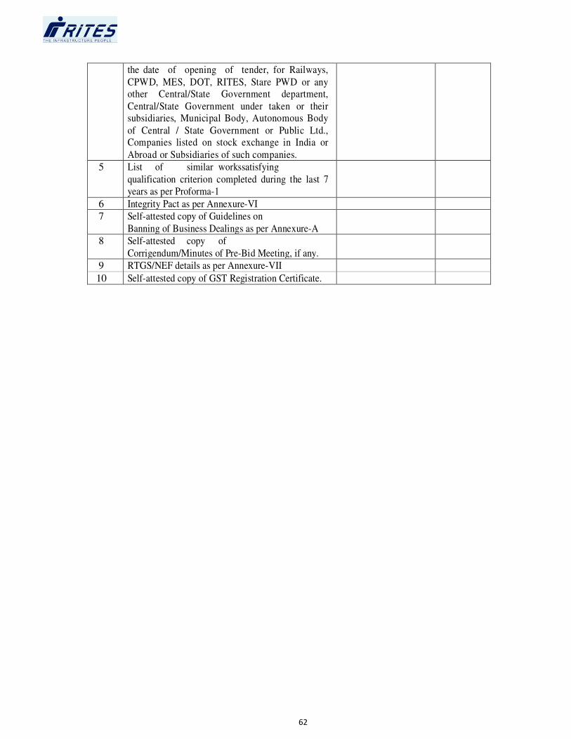
62
the date of opening of tender, for Railways,
CPWD, MES, DOT, RITES, Stare PWD or any other Central/State Government department,
Central/State Government under taken or their subsidiaries, Municipal Body, Autonomous Body
of Central / State Government or Public Ltd., Companies listed on stock exchange in India or
Abroad or Subsidiaries of such companies.
5 List of similar workssatisfying
qualification criterion completed during the last 7
years as per Proforma-1
6 Integrity Pact as per Annexure-VI
7 Self-attested copy of Guidelines on
Banning of Business Dealings as per Annexure-A
8 Self-attested copy of
Corrigendum/Minutes of Pre-Bid Meeting, if any.
9 RTGS/NEF details as per Annexure-VII
10 Self-attested copy of GST Registration Certificate.

63
ANNEXURE X
List of 60 Districts covered under IAP:
S.No. State District
1 Andhra Pradesh Adilabad
2 Andhra Pradesh Khammam
3 Bihar Arwal
4 Bihar Aurangabad
5 Bihar Gaya
6 Bihar Jamui
7 Bihar Jehanabad
8 Bihar Nawada
9 Bihar Rohtas
10 Chhatisgarh Bastar
11 Chhatisgarh Bijapur
12 Chhatisgarh Dantewada
13 Chhatisgarh Jashpur
14 Chhatisgarh Kanker
15 Chhatisgarh Kawardha
16 Chhatisgarh Koriya
17 Chhatisgarh Narayanpur
18 Chhatisgarh Rajnandgaon
19 Chhatisgarh Surguja
20 Jharkhand Bokaro
21 Jharkhand Chatra
22 Jharkhand Garhwa
23 Jharkhand Gumla
24 Jharkhand Hazaribagh
25 Jharkhand Kodarma
26 Jharkhand Latehar
27 Jharkhand Lohardaga
28 Jharkhand PachimSinghbhum
29 Jharkhand Palamu
30 Jharkhand PurbiSinghbhum
31 Jharkhand Ram Garh
32 Jharkhand Saraikela
33 Jharkhand Simdega
34 Madhya Pradesh Anuppur
35 Madhya Pradesh Balaghat
36 Madhya Pradesh Dindori
37 Madhya Pradesh Mandla
38 Madhya Pradesh Seoni
39 Madhya Pradesh Shahdol
40 Madhya Pradesh Sidhi
41 Madhya Pradesh Umaria
42 Maharashtra Gadchiroli
43 Maharashtra Gondiya
44 Orissa Balangir
45 Orissa Debagarh / Deogarh
46 Orissa Gajapati

64
47 Orissa Kalahandi
48 Orissa Kandhamal / Phulbani
49 Orissa Kendujhar / Keonjhar
50 Orissa Koraput
51 Orissa Malkangiri
52 Orissa Mayurbhanj
53 Orissa Nabarangapur
54 Orissa Nuapada
55 Orissa Rayagada
56 Orissa Sambalpur
57 Orissa Sonapur
58 Orissa Sundargarh
59 Uttar Pradesh Sonbhadra
60 West Bengal PaschimMedinipur

65
Annexure XI
Bid Security Declaration
(Affidavit on Non-Judicial Stamp Paper of Rs 10/- duly attested by Notary/Magistrate)
Date:................................. Tender No........................................................................
To
RITES Ltd.
…………….
The undersigned, declare that:
I/We understand that, according to your tender conditions, bids must be supported by a Bid Security Declaration.
I/We accept that I/We may be disqualified from participating for any tender of RITES Ltd. for a
period upto two years from the date of issue of LOA, if I am /We are in a breach of any obligation under the tender conditions, because I/We
a) Have withdrawn/modified/amended, impairs or derogates from the Bid in any respect during
the period of bid validity of your Bid; or
b) Fail or refuse to furnish the Performance Guarantee within the period specified under Clause
1 of “Clauses of Contract” or fails to commence the work without valid reasons within the
period as specified in Schedule F after the date of issue of Letter of Acceptance or from the
first date of handing over of the site, whichever is later.
I/We understand this Bid Security Declaration shall cease to be valid if I am/We are not the
successful bidder , upon the earlier of (i) the receipt of your notification of the name of the
successful bidder : or (ii) thirty days after the expiration of the validity of my/our Bid.
SEAL, SIGNATURE & NAME OF THE BIDDER
Signing this document
(Note: It is mandatory to submit the Bid Security Declarationalong with the bid documents
in place of Earnest Money. In case of a Joint Venture, the Bid Securing Declaration must be in the name of all partners to the Joint Venture that submits the bid)

66
SECTION- 2
TENDER AND CONTRACT FORM FOR WORKS
-DELETED-

67
SECTION-3
1. Special Conditions relating to existing Clauses of Contract
1.1 The construction/renovation of proposed siding falls in difficult area having scarce approach
road, limited space for labour/vehicle movement due to work to be executed in operation
yard.
1.2 The Contractor has to work along with other agencies in and around the area allotted for his
works. He should execute all his works in complete co-ordination and co-operation with all
such agencies and provide access to other agencies so that at no time either his work or the
work of other agencies is stopped or delayed. In case of any dispute in this regard, the
decision of Engineer-in-charge or his representative will be final and binding on the
Contractor. No Claim for idle labour, plant and machineries under any circumstances, will be
entertained by the NFR/RITES.
1.3 For work close to railway line, road telephone line, power line (both underground and
overhead) and structures, all precautions should be taken for ensuring that during the
excavation of foundation / execution of the work no damage is caused to such assets and
also no obstruction is caused to the movement of trains/road traffic.
1.4 APPROACH ROAD: - Contractor will provide approach road/roads for movement of materials
as per direction of Engineer-in-charge. Contractor will also maintain these approach roads in
safe and fit condition at his own cost. He will however have no authority to prevent use of
such roads by NFR/RITES and other bonafide contractors working at site. RITES will, however,
have the authority to disallow any movement on the road, which in their opinion is not in the
interest of work. If the contractor fails to provide service road to the satisfaction of the
Engineer-in-charge it will be provided by the Engineer-in-charge at Contractor’s cost.
However in case any such road is not required for the purpose of the work, nothing shall be
deducted from contractor’s payments on this account.
1.5 The contractor is required to execute the work in stretches/areas which are made available
to him and which may or may not be in continuous stretches. Decision of Engineer-in-charge
shall be final in this regard and binding on the contractor.
1.6 Contractor shall have no claim if the stretches /areas are not available for the construction
/repair at the same time. Extra time where requested by the Contractor on this account shall
be considered by the Engineer-in-charge on case to case basis.
1.7 The contractor shall provide a detailed schedule of work along with material and labour
deployment on monthly basis and revise or update the same every month.
1.8 The contractor will be required to establish a field laboratory for testing of compaction of
earth work/blanketing material, aggregate, cement, concrete, and other materials etc. The
contract shall provide qualified personnel to run the laboratory for the duration of the
contract. The number of staff and equipment available must at all times be sufficient to keep
pace with the sampling and testing program as required by the Engineer-In-charge or his
authorized representative.

68
1.9 The contractor shall procure all the materials well in advance (unless otherwise instructed by
RITES) so that there is sufficient time for testing of the materials and clearance of the same
before using in the works. Testing of the materials i.e. concrete cubes/reinforcement
steel/moorum/earth/cement/aggregate/ballast and any other materials shall be carried out
in Govt Engineering College, National Test House, RITES Laboratory at Liluah, or any other
approved laboratories as directed by Engineer In charge or authorized representative and as
per the frequency mentioned in relevant IS Code/QAP. Cost of testing of materials shall be
borne by the contractor.
1.10 The concreting work shall be done with proper and assured system of curing in duly
identified areas with date of concreting marked in paint. In hot weather the contractor shall
take relevant care to cover the work with wet gunny bags/ Hessian cloth or use continuous
sprinkling of water on surface so as to keep the surface wet.
1.11 The contractor shall, after completion of work, clear the site of all debris and left over
materials, at his own expense to the entire satisfaction of Engineer In charge or his
authorized representative.
1.12 Contractor should be registered with the concerned department of Employees Provident
Fund Organisation (EPFO). No payment shall be released to the contractor until and unless
the contractor submits the registration certificate and upto date deposit receipt of
provident fund due to be deposited by him.
1.13 At the time of submission of RA/Final bill a certificate shall be submitted by the contractor
regarding up to date clearance of payment to his/their sub-contractors, vendors, suppliers,
labour contractor etc. if any.
1.14 Contractor shall submit to RITES/NFR the entry challan of incoming materials like cement,
steel structural and reinforcement, ballast etc. for verification of Stores and record.
1.15 Contractor should maintain the daily cement consumption register. Engineer - in - charge or
his representative may check the registers and the challans at any time.
1.16 NIGHT WORK:- The contractor would be required to carry out the work even at night, without
conferring any right on the contractor for claiming for extra payment for introducing night
working. The decision of the Engineer-in-charge in this regard will be final and binding on the
contractor. Contractor shall make his own arrangement for sufficient illumination at site.
Nothing extra will be paid for doing works at night.
1.17 FIRST AID:-The contractor shall maintain in a readily accessible place first aid appliance
including an adequate supply of sterilized dressing and sterilized cotton wool. The appliances
shall be placed under the charge of responsible person who shall be readily available during
working hours.
1.18 The contractor shall also provide, fix & be responsible for the maintenance of all stakes,
templates profiles, levels marks, points etc. and must take all necessary precautions to
prevent these being removed altered or disturbed and will be held responsible for the
consequences of such removal, alteration or disturbances should the same take place and for
their efficient reinstatement.

69
1.19 HANDING OVER OF SITE:-
1.19.1 Efforts will be made by the Employer to hand over the site to the Contractor free of
encumbrance. However, in case of any delay in handing over of the site to the
Contractor, the Employer shall only consider suitable extension of time for the execution of
the work. It should be clearly understood that the Employer shall not consider any other
compensation whatsoever viz. towards idleness of contractor’s labour equipment etc.
1.19.2 The Employer reserves the right to hand over the site in parts progressively to the
Contractor. The Contractor will be required to do the work on such released-fronts in
parts without any reservation whatsoever.
1.19.3 The access roads near to the work site may not be available at the time of mobilization by
the Contractor. The Contractor shall plan his work within as per available roads at site. All
drainage of works area and all other weather truckable/haulage roads as required by the
Contractor shall be constructed and maintained during the construction period by the
Contractor at his own cost.
1.20 The Contractor has to make temporary diversion of course of water during execution of any
work conveniently free of cost.
1.21 The Contractor will bear all the charges for testing of materials, in site laboratory or from
other approved laboratories as certified by Engineer-in-Charge. Minimum 4 nos laboratory to
be set up within the entire stretch.
1.22 An experienced surveyor should be deployed at site by the contractor along with the Total
Station or equivalent equipment. Nothing extra will be paid for deploying experience surveyor
or equipment.
1.23 The Contractor will bear all the charges of design mix and the charges for testing of materials.
1.24 Contractor will have to arrange water supply and electricity connection at his own expenses
for his own establishments.
1.25 Contractor’s rate shall inclusive of cost of dewatering/shoring wherever required. No extra
payment shall be made for any type of dewatering/shoring during execution of the work.
2. The tenderer shall hold the offer open till such date as may be specified in the tender. It is
understood that the tender documents have been sold/issued to the tenderer and the
tenderer is being permitted to tender in consideration of the stipulations on his part that after
submitting his tender, he will not resile from his offer or modify the terms and conditions
thereof, in a manner not acceptable to RITES/NFR.
3. If a tenderer expires after the submission of his tender or after the acceptance of his tender, RITES shall deem such tender as cancelled. If a partner of a firm expires after the submission
of their tender or after the acceptance of their tender, RITES shall deem such tender as
cancelled unless the firm retains its character.

70
4. NFR/RITES also reserve the right to accept tender either for full quantity of work or part
thereof or divide the work amongst more than one without assigning any reason for any such
action.
5. When the tender is submitted by the tenderer(s), it will be understood that the tenderer(s)
has/have gone through carefully in detail all the instructions, conditions, General and
Special conditions of contract all General and Special instructions/ specifications for execution
of the work and that the tenderer(s) has/have got himself/ themselves clarified on all points
and doubts and interpretations by the proper authority of RITES.
6. Contractor's store houses, yards etc. for stocking materials issued by RITES shall be located in the site premises only at locations approved by Engineer-in-charge.
7. The laying & linking of railway track work consists of linking/laying of track ,PSC sleepers and
points & crossings including supply of hard stone ballast(machine crushed) of approved quality
and other P.Way materials. The work shall confirm to various specification indicated in Indian
Railway P.Way manual, track manual and permanent way IRS Drawing in use by Indian
Railway for such works, and should be fit for use of broad gauge engines, Rolling stock etc.
8. If there is any conflict between description given in schedule of quantity and conditions
mentioned in the special conditions, the schedule of quantity shall prevail.
9. Before commencing the work, joint inventory of existing materials in the track if any, are
to be taken by the representatives of RITES/NFR & the contractor and to be entered in the inventory register with jointly signed.
10. The P. Way materials as per “Schedule of Quantities” in the tender documents required for the
work and to be supplied by the contractor as per BOQ shall have to be supplied from RDSO
approved manufactures duly inspected by Railways/RDSO/RITES.
11. All P.Way materials required for the works and to be supplied free of cost by the employer as
per contract conditions will be issued to any of RITES/NF RAILWAY store Depot. or in stacks from time to time during the period of work. The contract should transport these materials for
use in the work by his own means of suitable transport, including loading, unloading, sorting, stacking with all lead, lift, crossing railway tracks etc.
12. Adequate protection should be made while moving on public Roads or adjacent and across
railway tracks. The rates quoted shall include cost of such items. Similarly the excess materials supplied free by the Employer shall be returned to the nominated stores of the NF
RAILWAY/RITES. No separate payments will be made extra for these items except where otherwise mentioned. The contractor shall include such expenses for items while quoting his
rates for the "SCHEDULE OF QUANTITIES".
13. It should be clearly understood that it is entirely the contractor’s responsibility and liability
to find, procure and use the required tools and plants and accessories at his own cost for
efficient and methodical execution of the work. RITES shall have the right to check the
sufficiency or quality of the Contractor's tools from time to time and the Contractor shall carry
out all reasonable instructions of RITES in this respect.
14. In the event of any accident at the works pot, or while transporting materials, if it is established
by the enquiry by RITES representative/Clients' representatives or Railway/local Civil
authority that the accident occurred wholly or partly due to any act tantamount to negligence on part of the contractor, he shall render himself liable for all damages and also legal proceedings.
71
15. In case the released P. Way materials are left over at site, the contractor has to employ
security/chowkidars day and night at his own cost till the P. Way materials are handed over to
the Engineer-in-Charge of work at his nominated depot. Till they are returned/handed over at
the nominated depot, the released materials will continue to remain in the custody of the
contractor.
16. The labour engaged by the contract for the works should be headed by a Railway retired permanent way inspector, employed by the contractor, who is conversant with the execution
and maintenance of P.Way works including safety rules.
17. Shifting of labour camp from place to place as the work advances will be at the cost of the
contractor.
18. The contractor will co-operate with the Engineer-in-Charge or his authorized representative in
maintaining various registers, charts and records etc. in connection with the works.
19. RITES representative should sign and maintain the following register and the contractor or his
authorized representative must sign on the registers as token of his acceptance of the entries
made therein.
(a) Register of materials issued
(b) Register of Ballast Stacks
(c) Register of Through packing
(d) Other relevant registers.
20. A separate register should also be maintained by the contractor for the deployment of contract
labour at site. The registers should be made available to Employer/RITES personnel, as and
when required.
21. While stacking P. Way materials (new or second hand or released) on cess/side, care should be
exercised to ensure that those stacks do not infringe the Railway's moving dimensions.
22. Time shall be regarded as the essence of the contract and failure on the part of contractor to
complete the work by the date stipulated in the agreement and work order will entitle
RITES Administration to recover liquidated damages/penalty.
23. RITES Administration reserve the right to alter the detailed plan and sections and to carry
out minor alteration in the plans resulting in corresponding increase or decrease in the
quantity of works without being liable to pay enhanced rates for the work or to allow extra time for completion of the work.
24. No new facilities such as roads, level crossing etc, other than those already in existence will be
made available to the contractor.
25. The Schedule of items of work to be carried out, provided in the SCHEDULE OF QUANTITIES” gives only brief description of each of the items. Execution of these items will
be governed by the Technical specifications. For detailed specifications reference may be
made to Section 5 “Technical Specifications” in general and in particular to the various
Guidelines and Specifications listed in Para 1.0 “Preamble to Technical Specification” of
Section 5. RITES' representative at site will be fully empowered to provide guidance in the matter of execution of the works and his instructions will be final and binding in this regard.

72
26. In case any workman is found incompetent or otherwise undesirable by the RITES'
representative at site, he should not be allowed to work under the Contractor. In this matter, the
opinion of the Engineer-in-Charge will be final and binding on the contractor. Any violation of
this requirement by the Contractor shall be treated as fundamental breach of contract entitling
RITES to rescind the contract by giving 7 days notice.
27. Particulars of work done during each day, with location where the work is done, will have to be
recorded in a register by the Contractor’s site in charge and the register will be kept available
for inspection/scrutiny by RITES’ representative. A site order book will also have to be
maintained where instructions regarding work to be carried out will be recorded by RITES'
representative at site.
28. RITES's representative shall have the right at all times to supervise the contractor's work and instruct the contractor and the contractor shall execute the work as per the instructions without
any lapse of time. For this purpose the Contractor shall maintain a Site Order Book. Failure to comply with RITES' representative's instructions shall be deemed to be a fundamental
breach of contract on the part of the Contractor entitling RITES to rescind the Contract at the Contractor's risk and cost after serving a notice of 7 days.
29. On-account payments to Contractor shall be made periodically based on the quantity and item
of work executed at the rates accepted under this contract, and upon a certificate by the
RITES' representative that work has been done to proper specification and to the
satisfaction of its representative.
30. The Contractor will make all arrangements for getting passes/authorities for his men including
making necessary application with photos for each labourer deployed for this work and will
bear all costs, if any. Housing accommodation and watering arrangements for contractor's
labour will have to be arranged by the contractor.
31. The Contractor will bear all medical expenses and make immediate arrangement for medical
attention to his labours, if injured on duty. He will provide "Medical Aid" Box at site of work at his cost.
32. Employer will only for supply items provide 'e-Way Bill' if applicable. The tenderers are
requested to quote their rates accordingly.
33. The rates quoted shall be inclusive of all taxes (Excluding GST) etc as applicable. You have to
raise Tax Invoice as per provision of GST rules and GST amount has to be charged separately in
bills. For all the above purposes your own GSTIN and GSTIN of the employer (NF RAILWAY) will
have to be used and not GSTIN of RITES in any case.
You are requested to furnish documentary evidence of deposit of GST or a copy of return in
case of adjustment of available input credit, whichever is earlier, before processing subsequent RA Bill. Else, the Engineer-in-Charge shall withhold the GST amount so paid in the previous
RA Bills, in the subsequent RA Bills.
Inspection charges and the charges for loading, transportation, unloading and stacking of
materials at store should not be quoted separately. The quoted rates should remain firm till
completion of the entire work.
34. The contract shall submit royalty clearance certificate and paid challan wherever applicable
along with every 3rd on account bill/running account bill and final bill. If the contractor fails to submit the royalty clearance certificate, requisite amount will be withheld as per extant
Government rules from his bill and to be released after submission of royalty clearance

73
certificate from the concerned department. Final bill shall be paid after submission of royalty
clearance certificate. And it is also governed by the Clauses of RITES GCC.
35. The tender is being invited on behalf of NF RAILWAY , payment will be made to the
Contractor only after fund is made available by NF RAILWAY/Client.
36. STORES TO BE SUPPLIED BY THE CONTRACTOR
i) All the P. Way items should be as per RDSO Drawing Numbers and shall comprise of all parts
and accessories listed in the Drawing except where otherwise stated. All P. way fittings &
fixtures, PSC Sleepers, Point & Crossings, DS etc. should be procured from RDSO approved
manufacturers only.
ii) The quoted rates should be inclusive of Inspection Charges and all taxes and duties of
Central, State, Local bodies (Excluding GST) including Loading, transportation, unloading and
stacking at site store as per the direction of Engineer-in-Charge or his authorized
representative of RITES Ltd. at RITES LTD, Lumding-Badarpur site. The quoted rates shall
remain firm during the currency of the Contract.
iii) Actual quantity delivered at site will be considered for the purpose of effecting payment.
iv) Inspection is to be carried out by the RITES Quality Assurance (QA) Division, Kolkata/New
Delhi/ Chennai/ Mumbai or Zonal Railways, as the case may be, before effecting dispatch of
the materials. Original Inspection certificates of the RITES Inspection Wing/Zonal Railways will
have to be submitted along with the bills as documentary evidence.
v) RITES Ltd on behalf of Northeast Frontier Railway (NFR) reserves the right to undertake any
test, if required, before acceptance of the materials on contractor's cost.
vi) Any materials and accessories, found to be damaged at the time of receipt will not be
accepted and shall have to be replaced by good ones free of cost after being duly inspected.
vii) Terms of payment: - 90% payment of P. Way materials will be made against delivery of
materials at site and on submission of bills along with the receipt / delivery challan, Inspection
Certificate. The bills in triplicate are to be raised in favour of RITES A/c, NF RAILWAY and are
to be submitted to Site-In-Charge, RITES Ltd. of NF RAILWAY at Lumding-Badarpur site
Balance 10% payment of P. way materials& Ballast shall be released after put into on track.
NOTE: In case of delay in fixing of P. Way materials on track for the reason not attributable to the
contractor, balance 10% payment will be released on receipt of the unused materials in good
condition and delivery at RITES/NF RAILWAY store as per the direction of Engineer In charge.
viii) Consignee of materials: - Site In-Charge, RITES Ltd, Lumding-Badarpur site / NF RAILWAY, or
his authorized representative on behalf of Employer/NF RAILWAY. However, on receipt of the
materials the same will be issued to the contractor and the contractor will be the custodian till
completion of the project.
ix) No Escalation will be paid for supply of P.way fittings & materials under Schedule-6
x) Secured advance, Mobilization advance will not be paid. As such relevant GCC clauses to be
treated as deleted.
37. Defect Liability period: As per clause 17 of clauses of contract in GCC applicable to this
work, the period of maintenance/defect liability period for this work shall be 24 (Twenty Four)
months from the date of issue of final completion certificate or till the final bill has been passed whichever is later.
74
38. After handing over of the existing section to the contractor, the same section will be maintained
and guarded by the contractor, till all the works are completed in all respect and handed over
back to the Engineer-in-charge.
39. Completion Drawings:
Completion drawings for the works executed shall be prepared by the contractor at his cost on
tracing paper. The contractor will supply five copies of ammonia print of completion drawing
duly signed along with original tracing plan and soft copy with the final bill.
40. The contractor will submit the following documents to RITES Site office within 15 days from
the date of commencement of work:
i) Performance Guarantee Bond
ii) Additional Performance Guarantee Bond If any
iii) License under the contract labour(R&A) Act and Rules
iv) Indemnity bond against patent Rights
v) Registration with Sale Tax department
vi) Insurance Policy on cost of works
vii) Third Party Insurance
viii) Workmen’s Insurance
ix) Indemnity bond on damages to persons and property
x) Registration with GST department
xi) Registration with labour department
xii)Bank Guarantee bond on free supply of materials, if any.
xiii)Indemnity bond against obeying Labour Law.
xiv) Indemnity bond against paying of Royalty against minor minerals.
41. The agency will mobilize men & machineries as per requirement at all front subject to
availability of front.
42. Rail will be free supplied to the contractor.
43. The contractor will be responsible for the safe custody of P. Way materials including Rails
issued to him till completion of the works and handing over the Track. The contractor will also
be responsible to account for the P-Way materials issued to him and surplus if any, has to be
returned by him at his cost at the depot from which these were issued. For P .Way materials
remaining not accounted for by being laid on track or returned to the depot, recovery will
be effected from the contractor's dues at accepted rates of the materials plus 25% on the
same. No wastage, breakage allowance or loss is permitted for fixing of P. Way fittings and
materials supplied by the contractor.
44. The work of track linking at existing level crossings will be taken up only when specifically
authorized by RITES representative after giving due notice to road users. The road surface will
be made good on completion of works at contractor’s cost, to the original standard. No extra
payment for digging up road surface for the work and restoring the road surface will be
admissible for work at level crossings.
45. The contractor should indemnify and save harmless RITES/NF RAILWAY against any claims on
account of accident to laborers similar occurrence for any reason whatsoever.
46. Tenderers may please note: -
i)Client of RITES Ltd. also termed as “Employer” is “NF Railway”.
ii)It should also be stated that the Client is the Principal as well as Employers for this work.
iii)In case of any dispute between RITES Ltd. and Contractor, RITES Ltd. being merely an agent,
client should be made first respondent and should be liable for all monetary losses.
iv)RITES Ltd. is only agent/consultant acting on behalf of the client/employer and in case of
arbitration, the client shall be the first respondent.

75
47. Every month the contractor will issue a certificate to RITES about having made full payment to
all labours/suppliers/venders under him engaged for this work.
48. EMPLOYMENT OF LOCAL LABOUR
Contracts are to employ, to the extent possible, only local project affected people and pay
wages not less than the minimum wages fixed by the Law of Land.
49. Contractor shall provide a four wheeler (Bolero/Scorpio) with driver & Fuel in running
condition to RITES/Railway/NF RAILWAY official for day to day site inspection/ supervision of
work. Vehicle make should not be more than 02 years old. No payment shall be made against
the supply of vehicle, driver & fuel. Maintenance of vehicle is the responsibility of contractor.
Average running per day shall be 100 Km.
76
2. Special conditions for supply of Ballast
1.1 The rates, as per the Schedule, are inclusive of all taxes viz. commercial sales tax, octroi etc.
and other charges levied by the State / Central government. The rate also includes all lead,
lift, ascent, descent, loading, unloading, royalty etc. and all other incidental charges.
1.2 The contractor shall stack the ballast, normally over the entire length of the section at
specified locations duly certified by the Engineer-in-Charge except at those certain locations
which are found to be inaccessible for certain reasons. The decision of Engineer-in-Charge at
site will be final and binding on the contract for the locations, inaccessible for supply of
ballast.
1.3 The ballast shall be supplied as per the requirement given by the In-Charge at site.
1.4 The ballast shall be in conformity with the latest “Specifications for Track Ballast”.
However, the RITES administration may alter these conditions of technical nature, which do
not have bearing on rates.
1.5 The tenderer/contractor undertakes that the ballast supply at all times shall conform to the
latest specifications for track ballast as specified by RITES.
1.6 The contractor shall make his own arrangement at his own cost for the construction of
service roads within the Project site as well as outside Project site for transportation of
ballast, if required. No separate payment shall be admissible to the contractor for the
construction of such roads and its repairs & maintenance.
1.7 The contractor shall have to make necessary arrangement for levelling the nominated
grounds for stacking of ballast at cess, as per the direction and to the satisfaction of
Engineer-in-Charge, without any additional claim of payment.
1.8 The contractor shall submit the name of the quarry/quarries along with the tender from
where the contractor is intending to supply the ballast, for acceptance of the same by RITES
Engineer.
1.9 The cost of routine testing of ballast, as per RDSO guidelines shall be payable by the
contractor. However RITES/NF RAILWAY is at liberty to collect the ballast sample as and
when, required and send the same for testing at the cost of Contractor.
1.10 The quantities of ballast mentioned in the schedule are approximate. RITES reserves the
right to alter the quantity as per the actual requirement and nothing extra will be payable
over and above the accepted rates.
1.11 The contractor shall make necessary arrangement for the security of the ballast supplied
during the progress of the work till final bill is paid. No separate payment shall be admissible
to the contractor for guarding the ballast.
1.12 The ballast shall be supplied as per the requirement given by the Site Engineer. Quantity
supplied extra over the required quantity may not be paid.

77
1.13 Safety of ballast against any theft or loss remains solely with the contractor during the entire
period of the contract agreement and the same has to be made good by contractor. This
responsibility of the contractor remains even if the ballast stacks are measured and paid for,
unless RITES /EMPLOYER takes over measured ballast stacks from the contractor with a clear
taking over certificate.
1.15 The Stone ballast should be machine crushed and shall consist of hard and durable and as
far as possible angular along edges/corners, free from weathered portions of parent rock,
organic impurities and inorganic residues.
1.16 The Tenderer should mention in the tender the name of quarry from where the ballast is
proposed to be supplied and the distance of the quarry from site.
1.17 The stone ballast should be got inspected by the Engineer at regular intervals/as per
frequency of testing in Railway/RITES specification to ensure quality and samples tested for
physical properties (abrasion test, impact test and water absorption test values). Necessary
Test charges shall be borne by the agency.
1.18 Attempts should be made to have ballast of the best available quality.
1.19 90% of the payment will be paid in R.A. bills prepared against supply of ballast duly certified
by Engineer-in-Charge of RITES Ltd or his authorized representative supported with
measurement details, test certificates, royalties and all other necessary statutory taxes,
clearance certificates etc. Balance 10% shall be released after spreading the same in to the
track
NOTE: In case of delay in spreading of Ballast on track for the reason not attributable to the
contractor, balance 10% payment will be released as per the direction of Engineer In
charge.
1.20 The rates in this schedule are entirely inclusive so as to cover any purchase and/or royalties
and / or compensation for surface charges incurred by him whatsoever. The accepted rate
includes all quarry charges monopoly fee and other charges if any and tools and plants for
clearing site for stacking, test and testing screens, carriage of materials to the site of stacking
and removal of any material rejected by the Engineer to any site when the rejected materials
are to be thrown.
1.21 The rates quoted are inclusive of all charges including all taxes (excluding GST) levied by Union
of India or State Government or local bodies etc.

78
3. SPECIAL CONDITIONS OF CONTRACT FOR THERMIT WELDING
The work consists of welding in situ 60 /52 Kg. rail (72 UTS/90 UTS) joints by Fusion Welding
of Rails by Alumino-Thermic Process.
1. The 'portion' used for welding shall conform to the technical requirements as mentioned in
IRST-19-2012 incorporating up to date A&C SLIP The suitability of the 'portion' for the
welding process in respect of the type and section of rails to be welded shall be ensured
before commencing welding. Only RDSO certified/passed portions should be used for
welding.
2. The contractor shall execute the work at the rates and terms and conditions specified in the
contract and within the time schedule as indicated in the Work Orders.
3. The work done shall conform to IRS Specification No. IRST-19-2012 for fusion welding of
rails by Alumino Thermit process using Single shot crucible. A copy of this specification is
attached as Annexure "2" stipulation laid down therein shall apply to this except as modified
or clause herein under.
4. No payment will be made for the spoilt joint exceeds 2% of the total of good joints.
5. The NF RAILWAY/RITES will provide rails for making welds.
6. A guarantee as specified in clause 3.6.1/3.5.2 of Annexure 2 shall be furnished by the
contractor for the completed weld joints against Work Order.
7. The marking of welded joints as specified in clause 3.6.3 of the Annexure "2" shall be done
by the contractor at his cost.
8. The contractor shall procure all the necessary welding materials as well as all the equipments
for the welding works so as to use a finished weld including the necessary planning
equipments at his own cost and he will be paid only for the finished work at rates quoted in
the Schedule of items.
9. The contractor shall provide all labour required for the work and the contractor shall
arrange to train the labour in the welding technique and shall also be responsible for
providing constant technical supervision during the process of welding work. The welder
should be RDSO trained and certified by RDSO. The welder’s certificate obtained from RDSO
shall have to be furnished prior to start of work for welding.
10. The contractor shall be responsible for the correct alignment and welding of the rails and for
the proper plain by hand filing of the welds and their finish. The files are to be supplied by
the contractor at his cost.
a) The contractor shall provide pieces of wooden sleeper wedges and such other tools
which are required for lifting or making or placing rail in position for welding purpose
and also hammer and hot and cold sets required for the works.
79
(b) The contractor shall provide fuel like petrol required for welding at the rate of 2.00
liters of petrol per joint. The quantities may vary within 10%.
c) All other equipments& machineries used by the contractor in grinding or plaining etc.
should be worked out by him at his own cost including labour for this work.
11. The contractor shall arrange his own facilities for carrying out of all plants & equipment and
materials from nearest store to site of work.
12. The Contractor shall arrange storage accommodation for his plants &equipments as close to
the site of work.
13. The contractor shall not carry out any works between sunset and sunrise. He should make
his own arrangement to protect the work against wind and weather in the course of
execution of work.
14. The security deposit shall be retained by the RITES free of interest for the guarantee period
of one year (Para 3.6 of Technical Specifications for Thermit Welding) from the date of
welding the joints in track or from the date such welded joints made 'in cess' are inserted
in the track. Any such welded joint which fails within the guarantee period shall be rewelded
free of cost by firm as per stipulations of para 3.4 of Technical Specifications for Thermit
Welding.
15. Payment shall be made for acceptable joints in terms of the agreement and for the spoilt
joints upto 2% of the total of good joints. Further joints which will be put for tests, the
contractor will be paid provided they stand the test. Test joints which will be failed will not
be paid for.
16. The rate for welding work shall be excluding GST.
17. The contractor shall be responsible for the welded joints remaining satisfactory for the
guarantee periods as specified and every joint failing during this period 3 times the cost of
one weld will be recovered from the amount due to him.
18. The account of sealed approved portions and statement of issue of approved portion shall be
maintained by the RITES representative of the welding but the account and statement in
question will have to be countersigned by the authorized representative of the contractor.
The account shall correlate the welding panel on the pieces number with the approved
portion and the date of welding.
19. In the event of failure of weld joints which are not possible to weld on that very day, the
joints must invariably be fastened with joggled fish plates duly clamped. The joggle fish
plates and clamps are to be arranged by the contractor at his own cost.
20. The plants, equipments, consumables materials, Technical Supervisors, Artisan staff, Welders
and other labours required for the work shall have to be arranged by the contractor at his
own cost.

80
21. Any electric supply required at site for what-so-ever purpose shall be arranged by the
contractor at his own cost and rates quoted shall include the cost of providing electric supply
arrangements required for the work.
22 Sample test joint.
22.1 One out of every 100 joints welded shall be selected at random by the purchaser or by the
inspecting officer within one month of welding and subjected to hardness,
transverse load/ deflection tests and porosity as per clause 4.2 of IRST-19-2012 ( reproduced
partly as Annexure 9 for ready reference) and the joint shall comply with the provisions
laid downs therein.
22.2 If the sample test joint fails to satisfy any of the requirements of specification IRST-19-
2012, the RITES will be at liberty to suspend further welding. However, two more
randomly selected joints from the same lot of 100 joints shall be subjected to re-tests as per
clause 4.2 of IRST-19-2012. Both the joints should clear all the tests. If this report is also not
satisfactory, further welding of joints shall be suspended until the firm's welding technique
has been examined and the same satisfies the requirements of Clause 4 by welding one test
joint as per IRST-19-2012.
23 Guarantee
23.1 Rail joints welded by a firm shall be guaranteed against failure which includes failures in
execution, acceptance, acceptance & regular ultrasonic testing and during service up to one
year from the date of welding the joints in track or from the date such welded joints made ‘in
cess’ and inserted in the track. Any such welded joints which fail in the criteria given above
within the guarantee period shall be re-welded free of cost by firm as per stipulations Para
3.4
23.2 In case of failure of sample test joint (refer Para 3.5), the period of guarantee for 100 joints
represented by the sample joint shall be extended for a further period of one year. In case of
failure of joints or joints exhibiting signs of failure by cracking within extended period of
guarantee, the joints shall be re-welded free of cost by the supplier as per stipulations of
Para 3.4.
23.3 The welded joints with the extended period of guarantee shall be marked 'X' with yellow
paint one the outer side of the web of the rail near the joint in addition to the marking
prescribed in Para 2.6. Such marked joints shall be kept under careful observation by the
purchaser.

81
(2) Additional Special Conditions
SPECIAL CONDITION RELATING TO UPLOADING OF PAYMENT OF WAGES AND OTHER
PAYMENTS TO CONTRACT LABOUR ON RAILWAY WORKS
A) Contractor is to abide by the provisions of Payment of Wages act & Minimum
Wages act in terms of clause 19 B of RITES’ General Conditions of Contract for
Works. In order to ensure the same, an application has been developed and hosted
on website ‘www.shramikkalyan.indianrailways.gov.in’. Contractor shall register his
firm/company etc. and upload requisite details of labour and their payment in this
portal. These details shall be available in public domain. The Registration/updation
of Portal shall be done asunder:
a) Contractor shall apply for onetime registration of his company/firm etc. in the
Shramikkalyan portal with requisite details subsequent to issue of Letter of
Acceptance. Engineer-in-Charge shall approve the contractor’s registration on the
portal within 7 days of receipt of such request.
b) Contractor once approved by the Engineer-in-Charge can create password with
login ID (PAN No.) for subsequent use of portal for all LOAs pertaining to Railway
works issued in his favour.
c) The contractor once registered on the portal, shall provide details of his Letter of
Acceptances (LoA)/Contract Agreements on shramikkalyan portal within15 days
of issue of any LoA for approval of concerned engineer. Engineer-in- Charge shall
update (if required) and approve the details of LoA filled by contactor within 7
days of receipt of such request.
d) After approval of LoA by Engineer-in-Charge, contractor shall fill the salient
details of contract labours engaged in the contract and ensure updating of each
wage payment to them on shramikkalyan portal on monthly basis.
e) It shall be mandatory upon the contractor to ensure correct and prompt
uploading of all salient details of engaged contractual labour& payments made
thereof after each wage period.
B) While processing payment of any ‘On Account bill’ or ‘Final bill’ or release of
‘Advances’ or ‘Performance Guarantee/Security deposit’, contractor shall submit a
certificate to the Engineer-in-Charge or his representatives that “I have uploaded
the correct details of contract labours engaged in connection with this contract and
payments made to them during the wage period in Railway’s Shramik kalyan portal
at ‘www.shramikkalyan.indianrailways.gov.in’ till Month, Year”

82
SECTION- 4
SCHEDULES A to F
83
SECTION 4 PROFORMA OF SCHEDULES
SCHEDULE ‘A’
Schedule of Quantities (As per Bill of Quantities attached)
SCHEDULE ‘B’ – NOT APPLICABLE
Schedule of materials to be issued to the contractor. (Refer Clause 10 of Clauses of Contract)
S.No Description of items Quantity Rates in Figures & words at
which the material will be
charged to the contractor
Place of Issue
1 2 3 4 5
SCHEDULE ‘C’ –- NOT APPLICABLE
Tools and plants to be hired to the contractor. (Refer clause 34 of Clauses of Contract).
S.No Description Hire charges per day Place of Issue
1 2 3 4
SCHEDULE ‘D’ - NOT APPLICABLE -
Extra schedule for specific requirements/documents for the work, if any.
SCHEDULE ‘E’–
Schedule of component of Cement, Steel, Other materials, POL, Labour etc. for price escalation. (Refer Clause
10CC of Clauses of Contract).:
CLAUSE 10 CC APPLICABLE
Component of Cement (Xc),
expressed as percent of total value of work.
: 10 %
Component of Steel (Xs),
expressed as percent of total value of work.
: 20 %
Component of other Materials (XM),
(Except cement & steel) expressed as percent
of total value of work.
:
35 %
Component of Labour (Y),
expressed as percent of total value of work.
: 20 %

84
Component of P.O.L (Z),
expressed as percent of total value of work
: 15 %
TOTAL : 100 %
SCHEDULE ‘F’
Reference to General Conditions of contract
Name of Work - :
Estimated cost of work - : Rs. 43,97,81,242/-
Earnest money: : Bid security declaration as per Annexure XI to be
submitted.
Performance Guarantee (Ref. Clause 1) - : 3% of Tender value.
Security Deposit: (Refer clause 1A) - : 5% of Tender value.
Notice Inviting Tender and Instruction to
Tenderers - Officer inviting tender:
:
General Manager (Project), RITES Ltd, Regional
Project Office, Kolkata
CONDITIONS OF CONTRACT
Definitions
2 (iv) Employer : Northeast Frontier Railway (NFR)
2 (v) Engineer-in-Charge : General Manager (Project), RITES Ltd, RITES Ltd,
Regional Project Office, Kolkata
2 (vi) Engineer : The Person to whom the Engineer-in-charge
entrusts as his authorized representative his
responsibility to act on his behalf and perform any
or all the functions of the Engineer-in-charge
under the Contract.
2 (vii) Accepting Authority : ED/RP, RITES Ltd, Corporate Office, RITES Bhawan,
No.1, Sector-29, Gurgaon-122001
2 (ix) Percentage on cost of materials and
labour to cover all overheads and
profits.
:
15%
2 (x) Standard Schedule of Rates : NORTHEAST FRONTIER RAILWAY - UNIFIED
STANDARD SCHEDULE OF RATES -2010, DSR-2018
2(xiii) Date of commencement of work 15 days from the date of issue of LOA or the first
date of handing over of site whichever is later.
9(a)(ii) General Conditions of Contract : RITES General Conditions of Contract, July’ 2019.
(Read up to CS - 10)
85
CLAUSES OF CONTRACT.
Clause 1.
:
i) Time allowed for submission of
Performance Guarantee (P.G.) from the
date of issue of Letter of Acceptance.
:
15 days
ii) Maximum allowable extension beyond the
period provided in (i) above.
:
07 days.
Clause 2.
Authority for fixing compensation under
Clause 2
: ED/RP, RITES Ltd, Corporate Office, RITES
Bhawan, No.1, Sector-29, Gurgaon-122001
Clause 2A.
Whether Clause 2A shall be applicable
:
NO
Clause 5.
5.1(a) Time allowed for execution of work
Date of start
:
:
14 (Fourteen) months from the date of
start
15 Days from the date of issue of Letter of
Acceptance or the first day of handing over
of the site whichever is later.
5.1 (b) TABLE OF MILESTONE(S) – NOT APPLICABLE.
Clause 5A – Shifting of stipulated date of completion.
Competent Authority
:
ED/RP, RITES Ltd, Corporate Office, RITES
Bhawan, No.1, Sector-29, Gurgaon-122001
Clause 6A (Computerized Measurement book): NOT APPLICABLE.
Clause 7 (Payment on intermediate
certificates to be regarded as
Advances) Gross work to be done together with net
payment/adjustment of advances for material collected, if any, since the last
such payment for being eligible to interim payment
:
Rs. 2.50 Crore

86
Clause 10A (Materials to be provided
by the Contractor):
i. Whether Material Testing
Laboratory is to be provided at site.
ii. If “YES” list of equipment to be provided
:
:
Yes, minimum 4 Nos of Laboratory should
be set up in the entire stretch. Contractor shall at his own expense, provide a
fully equipped material testing lab at the site for
conducting routine field tests.
Clause 10 B Whether Clause 10 B(ii) to (vi)
applicable.
:
Not Applicable
Clause 10 CC. Whether Clause 10CC is applicable.
: Applicable
Clause 11 Specifications to be followed for execution
of work
:
Civil Work :(Considering Latest revisions)
a) RDSO Guideline on earth work
b) RITES Technical Specification c) CPWD Specification d) Relevant IRS Bridge Codes e) Concrete Code IS 456:2000 f) IRPWM
g) RDSO Specification on Alumino Thermit
Welding
h) RDSO Specification on Track ballast
Clause 12 :
Clause 12.2,12.3 & 12.5
Deviation Limit beyond which Clauses
12.2,12.3 & 12.5 shall apply
:
i) For Non-foundation items.
Plus 25%
Minus No limit
: ii) For Foundation Items.
Plus 100%
Minus No limit
: Note: For Earthwork, individual classification
quantity can vary to any extent but overall
Deviation Limits will be as above.
12.5 Definition of Foundation item if
other than that described in Clause 12.5
: All Excavation in Bridge/Building /Sheds /Drain
Foundation.
Clause 16 Competent Authority for
deciding reduced rates
: ED/RP, RITES Ltd, Corporate Office, RITES
Bhawan, No.1, Sector-29, Gurgaon-122001
Clause 17 Maintenance Period : 24 (Twenty Four) Months.
Clause 18 List of mandatory machinery,
tools & plants to be deployed
: As decided by Engineer-in-Charge during

87
by the Contractor at site:-
execution of work.
Clause 25
25 (i) Appellate Authority:
: Executive Director
RITES Ltd, Corporate Office, RITES Bhawan,
No.1, Sector-29, Gurgaon-122001.
Appointing Authority:
: Director Projects, RITES Ltd, Corporate Office,
RITES Bhawan, No.1, Sector-29, Gurgaon-
122001
Whether Clause 31A or 32 is applicable : APPLICABLE.
Clause 36 (i) & (iii)
Minimum Qualifications & Experience
required and Discipline to which should
belong.
:
APPLICABLE.
Designation. Minimum Qualification. Minimum
working
experience
(Years).
Discipline to
which should
belong.
Numb
er.
Principal
Technical
Representative
Degree in Civil Engineering 10 years Civil 1
Principal
Technical
Representative
Degree in Electrical
Engineering
5 years Electrical 1
Deputy Technical
Representative
Degree in Civil Engineering 5 years Civil 1
Site Engineer Degree in Civil Engineering
Or,
Diploma in Civil Engineering
2 years
Or,
5 years
Civil 2
P-way Expert Degree/Diploma/Retired PWI
from Indian Railway
5 years Civil 1
Surveyor Graduate 2 years - 1
Chainman Graduate - - 1
Note: Chainman shall work under EIC/RITES to assist in inspection & measurement.
Clause 36 (iv)
Recovery for non-deployment of Principal
Technical Representative/ Deputy
Technical Representative/Project
/site/Planning/Billing Engineer:
APPLICABLE.
Designation. Rate of recovery per month (in Rs.) for non-
deployment.
Principal Technical Representative. : Rs. 50,000.00
Dy. Principal Technical Representative : Rs. 40,000.00
Site Engineer / P-way expert : Rs. 25,000.00

88
Surveyor / Chainman : Rs. 15,000.00
Clause 42 Not Applicable
i)(a) Schedule / statement for
determining theoretical quantity of
cement & bitumen on the basis of Delhi
Schedule of Rates printed by CPWD.
: NORTHEAST FRONTIER RAILWAY-UNIFIED
STANDARD SCHEDULE OF RATES -2010, DSR-2018
ii) Variations permissible on
theoretical quantities:
a) Cement
- for works with estimated cost put
to tender not more than Rs. 5
lakhs.
:
3% (plus/minus)
- for works with estimated cost put
to tender more than Rs.5 lakhs.
: 2% (plus/minus)
b) Bitumen for All Works.
: 2.5% plus only & nil on
minus side.
c) Steel Reinforcement and structural
steel sections for each diameter,
section and category.
: 2% (plus/minus)
d) All other materials. : NIL
RECOVERY RATES FOR QUANTITIES BEYOND PERMISSIBLE VARIATION.
Sl.
No.
Description of Item. Rates in figures and words at which recovery shall be
made from the Contractor.
Excess beyond
permissible variation.
Less use beyond the
permissible variation.
1 Cement
NOT APPLICABLE.
2 Steel reinforcement
3 Structural Sections
4 Bitumen issued free
5 Bitumen issued at stipulated
fixed price
Clause 46
Whether Clause 46.10 shall be applicable
Details of temporary accommodation
including number of rooms and their sizes
as well as furniture to be made available
by the Contractor
:
NOT APPLICABLE.

89
Whether Clause 46.11.1A shall be
applicable. : Yes
Whether Clause 46.13A shall be
applicable. : NO
Clause 46.17 :
City of Jurisdiction of Court. : Kolkata
Clause 47.2.1
Sum for which Third Party Insurance to be
obtained.
: Rs. 5.0 lakhs per occurrence with the
number of occurrences limited to four.
Clause 55 :
Whether clause 55 shall be applicable. : NO
If yes, time allowed for completion of
sample floor/unit. : NO

90
SECTION-5
TECHNICAL SPECIFICATIONS
91
SECTION 5.
TECHNICAL SPECIFICATIONS
PREAMBLE: ALL TECHNICAL SPECIFICATION SHALL BE GOVERNED BY THE
RELEVANT IS CODE/ RDSO GUIDELINES/IRS BRIDGE CODE/IRPWM
WITH UPTO DATE CORRECTION SLIP.
� EARTHWORK IN RAILWAY FORMATION
1.1 EARTHWORK – GENERAL
1.1.1 RDSO Guidelines: For survey, design and execution of earthwork in railway formations,
RDSO has issued detailed guidelines as “Comprehensive Guidelines and Specification for
Railway Formation – Specification No. RDSO/2020/GE: IRS-0004, Sep-2020. These
Guidelines including their subsequent amended/revised versions, if any, shall apply to
execution of earthwork in railway formations. These guidelines or their amended/revised versions have subsequently been referred to in this chapter as ‘RDSO Guidelines’. In case of
any conflict between provisions of this chapter and those of RDSO Guidelines, the latter shall prevail.
1.1.2 Site Clearance: - Before work is started, the whole area between the toes of banks or tops of cuttings
plus 1m additional width on both sides shall be properly and effectively cleared by the contractor of
all vegetation, small trees of girth upto 30 cm (measured at a height of 1m above ground level),
roots, bushes, heavy grass etc; The Contractor shall also clear the site of all buildings, abandoned
structures etc as directed by the Engineer, for which extra payment will be made. The Contractor
shall arrange removal of rubbish and other excavated material excluding earth upto a distance of 100
metres outside the periphery of the area under site clearance. Top soil obtained from site clearance
as well as top layer of borrow pits which is rich in organic content and suitable for plant growth, if
directed by the Engineer, may be stored for covering slopes of embankment and cuttings after
construction. High portions of the ground shall be cut down and hollow depressions, if any, filled up
with suitable excavated soil duly compacted and the ground dressed and levelled. The work of this
nature will be covered by the initial rate for earth work, unless stated to the contrary in the
agreement.
1.1.2.1 Trees of girth over 30 cm, measured at a height of 1m above ground level, shall be considered
as large trees. Cutting down of large trees shall be paid extra at the rate specified in the Schedule of Rates. The rate shall include lopping of branches, trimming, removal from and
clearing of site when stumps are grubbed up in addition. Large trees shall not be cut without specific orders from the Engineer. As few trees shall be cut as is absolutely necessary for the
execution of work. The roots of trees and saplings shall be removed to a depth of 60 cm below ground level or 30 cm below formation level or 15 cm below subgrade level,
whichever is lower. All holes or hollows formed due to removal of roots shall be filled up with earth rammed and levelled. Trees, shrubs, poles, fences, signs, monuments, pipe lines,
cable, etc adjacent to the area which are not required to be disturbed during site clearance
shall be properly protected by the contractor at his own cost and nothing extra shall be
payable.
1.1.2.2 Any trees cut down or building materials released from dismantling of structures shall be
stacked by the contractor within a distance of 100 metres outside the periphery of the area
under site clearance as per instructions of the Engineer. The contractor shall have no claim to

92
the trees or other material removed during site clearance and the same shall be the property of
the Railway.
1.1.3 DATA AND SETTING OUT:
(a) Initial Data
At the commencement of work, the Engineer In charge shall give to the contractor the
following data/ guidance.
(i) Concrete centre line pillars fixed on the alignment at intervals of 250m
Pucca level bench marks fixed along the alignment, about 30 m away from the centre line
at intervals of 500m. These bench marks shall have been connected by levelling to
available GTS bench marks and the reduced level of each shall be communicated.
(iii) Longitudinal section of the proposed formation to scale 1:2500 horizontal and 1:500
vertical with the existing ground level and the proposed formation level marked at
intervals of 50m along the alignment and with the location of each curve, bridge, culvert,
and level crossing on the entire alignment indicated.
(v) Existing ground level would be jointly recorded by the Engineer-in-Charge or his
representative and the contractor or his representative by taking cross section at an
interval of 25m or as suitable so as to produce the general existing ground profile. The
Contractor will have to sign the level book as a token of acceptance of the level and it will form the original record for payment.
(vi) Ground levels recorded as above would be plotted to a natural scale 1:100 at a subsequent date and desired profile of bank/cutting would also be plotted on it. This will also be
signed by contractor and would be the basis for the final payment of earth work to be done.
(vii) The contractor shall be responsible for subsequent preservation of all the above mentioned pillars and drawings and shall pay for the cost of their replacement, if
necessary.
(b) Setting out:
Before commencement of earth work, the Contractor shall demarcate with a furrow, at least
20 cm wide and 15 cm deep, at 50 cms from the the toes of slopes of banks and outside limits of tops of cuttings on both sides of centre line and the boundaries of the bottom and top of the
borrow pits. The “dag belling” is to be maintained and renewed when necessary, throughout the duration of earth work. The cost of this is included in the rate for earth work.
Concrete pillars of 30 cms square at 50 cms away from and on both sides of the toe of the
bank / top of cutting at each cross section would be constructed and maintained by the
contractor at his own cost as a part of the setting out works. These concrete pillars should be embedded to a depth of 50 cms. No extra payment on this account is permissible. He will also
provide and maintain templates, burjies, reference pillars etc and shall take all necessary precautions to prevent these being removed, altered or disturbed and will be responsible for
the consequence of such removal, alteration or disturbance and for their efficient reinstatement. No extra payment will be made on this account.
(c) Profiles:
In accordance with cross sections supplied, the Contractor shall at his own expense provide
all stakes, bamboos, strings, pegs and labour for setting out profiles at every 25m or as
directed for correct execution of the work. This will include provision of side drains and catch water drains as necessary in cutting and / or as marked in the cross sections supplied to
the Contractor. The top of formation shall invariably have cross slopes of 1:30.

93
1.1.4 Mechanised construction of Earthwork: Manual methods of construction can not achieve
the desired quality of earthwork. Therefore in all projects, it is necessary to deploy
mechanised equipments such as earthmovers, dozers, hydraulic excavators, motor graders,
scrapers, dumpers, mobile water sprinklers, vibratory rollers, sheep foot rollers etc. so that
quality of work meets laid down standards.
1.1.5 Maintenance: Banks and cuttings are to be correctly dressed and finished in profile with
slopes as specified in each case. Where gullies or water-cuts commence to form on the slopes
of embankments or cuttings, the erosion is to be checked as early as practicable and made
good with suitable material well rammed into place. Where a gully or water-cut has not been
checked at its commencement, it may be advisable to cut it out or step it before filling it in, and to further protect the place by turfing, pitching or other means as may be ordered by the
Engineer. Work, before being finally paid for, is to be checked by the Engineer as having been correctly brought up, or carried down, to the proper level and to be otherwise complete
in all respects in accordance with the specifications.
1.1.5.1 As soon as the work has been satisfactorily completed, the Engineer shall issue a certificate of completion in respect of the work as specified in relevant Clause of the General Conditions of
Contract. Unless otherwise specified in the Tender conditions, the contractor shall maintain
the banks / cuttings, for a period of Twelve months from the date of completion of work as
indicated in the certificate of completion. The contractor shall be responsible for the handing
over of the banks/cuttings to the Railway in proper condition, and, where necessary, for their
restoration to such condition, at the end of the maintenance period. Until then, the contractor
is responsible for all losses due to subsidence, wastage or guttering due to rain, wind, wear,
wash or from any other cause whatsoever, and he shall have no claim for any extra work or
payment on this account.
1.1.6 Spoil from cutting to bank:- Up to the initial lead specified in the BOQ item, material from
each end of every cutting – subject to its suitability for use in railway embankment- shall be
led forward into the adjoining bank as a matter of course, and the rate to be paid for such
material shall be the rate for cutting only. The Engineer shall specify in each case from what point in each cutting to what point in the adjoining bank, spoil shall be led out, payment being
made only for the excess lead over and above the initial lead included in the rate for cutting. The Engineer can modify these limits at any stage of the work and all such changes shall be
binding on the contractor without any claim for any extra payment on this account. Dressing
and compaction of the bank will, however, be paid for in addition.
1.1.7 Classification of soils:- The classification of soil/rock met with in executing the work, if not
made by the Engineer, shall be made by the his representative authorized by him for this
purpose subject to the approval and final decision of the Engineer,. The rates to be paid to the contractor in his bills shall be based on these classifications.
Earth work shall be classified under the following heads:-
1.1.7.1 All kinds of Soils:- Generally any strata such as sand, gravel, loam, clay, mud, black cotton,
moorum, shingle, river or nallah bed boulders, soling of roads, paths etc. macadam surface of any description, lime concrete, mud concrete and their mixtures which for excavation yields
to the application of picks, shovels, jumpers, scarifiers, ripper and other manual digging implements.
1.1.7.2 Ordinary Rock: Generally any rock which can be excavated by splitting with crowbars or
picks and does not require blasting, wedging or similar means for excavation, such as lime
stone, sand stone, hard laterite, hard conglomerate and unreinforced cement concrete below ground level. If required light blasting may be resorted to, for loosening the materials but this
will not in any way entitle the material to be classified as ‘Hard rock’.

94
1.1.7.3 Hard Rock (Requiring Blasting):- Generally any rock or boulder for the excavation of
which blasting is required Such as granite, quartzite, basalt, reinforced cement concrete below
ground level and the like.
1.1.7.4 Hard Rock (Blasting Prohibited):- Hard rock requiring blasting as described under sub
para 1.1.7.3, but where blasting is prohibited for any reason and excavation has to be carried
out by chiselling, wedging or any other agreed method.
1.1.8 Measurements:- Cutting and banks are to be excavated and made up neatly to the lines
shown in the cross section as per approved construction drawing. No payment will be made for excess work done outside these lines except when such work is so ordered in writing by
the Engineer. However, in case of embankments, extra width constructed, as per Para 1.2.5.6, to ensure proper rolling and compaction which is subsequently cut and dressed to avoid loose
earth on the slopes shall not be paid for.
1.1.8.1 Should the Engineer so desire, he may, at any stage of the work, order the Contractor to increase or reduce the slopes of any cutting or bank or alter the formation level, in which case
the amount of work actually done will be paid for in accordance with the specifications and
the Schedule of Rates.
1.1.8.2 Unless otherwise specified the rate for Earth work is inclusive of an initial lead and lift as
specified in the BOQ.
1.1.8.3 Additional lead for the purpose of payment will be measured from the centre of gravity of
excavation to the centre of gravity of the bank or spoil heap, and shall be measured along the
shortest practicable route and not necessarily the route actually taken.
1.1.8.4 Where initial lift is specified, additional lift for the purpose of payment will be estimated by dividing
the cross section of the bank or cutting into successive stages of 1.5m high or deep respectively from
the natural ground level and only the quantity contained in each strip shall be paid for at the rate
appertaining to its height or depth above or below the natural ground level, respectively. Lift from
the borrow-pit to the ground level or from ground level to the spoil bank shall not be taken into
account in any payment for lift unless the depth of the borrow- pit or the height of the spoil bank has
been made in excess of 1.5m under instructions from the Engineer, and in such cases, only the
portion of the borrow-pit below 1.5m depth or of the spoil bank above 1.5m height as measured
from the natural ground level, shall be, measured separately for payment of lift on the same basis as
for cuttings or banks respectively.
1.1.8.5 For the purpose of above para, the natural ground level shall be reckoned as that obtaining at the
toe of the bank nearest to borrow pits or at toe of spoil bank nearest to the cutting as the case may
be. No payment shall be made for any lift from the ground level at the borrow pit to that at the bank,
or from the ground level at the cutting to that at the spoil bank, where such lift is inherent in the lead
on account of natural ground slope and no obvious act of lifting is involved, in the opinion of the
Engineer. Obvious lifts such as involved in crossing of existing pits or banks, which cannot be avoided,
will be measured and taken into account for payment. In such cases, the additional lift thus
measured shall be taken into account in fixing the successive stage of 1.5m, whether in the bank or in
the cutting. In sidelong ground where borrow-pits or spoil banks, as the case may be, are made on
both sides, any payment for lift shall be a matter of special agreement.
1.1.8.6 For purpose of payment, cuttings shall be assumed to be composed of such soil / rock only, as
stand exposed on both or one side of the finished cuttings, depending upon whether the cutting is box type or one sided on a transversely sloping ground. The content of each type of

95
soil/rock thus assigned to any cross section shall be determined as indicated below. It is to be
noted that no portion of cutting will be payable for any such type of soil/rock as is not
exhibited on the finished side slope, where the side slope exists.
(a) For box type cutting:- The centre line of the alignment will be marked vertically on the
cross section and the content of each type of soil/rock will be determined by computing the
area of the strip, formed by joining the points, which form the extremity of occurrence of the
particular soil on the finished side slope of cutting, by straight horizontal lines terminating on
the centre line. Figure No.1.1 is illustrative of the manner in which payment is to be made.
(b) For one sided cutting on a transversely sloping ground:- Content of each type of soil/rock will be determined by computing the area of the strip, formed by joining the points, which
form the extremity of occurrence of the particular soil on the finished side slope of the cutting, by straight lines to the zero point. Figure No.1.2 is illustrative of the manner in which the
payment for the cutting will be made.
(c) For widening of existing cuttings for one or more lines where the existing cutting slope disappears and a fresh slope stands:- Before undertaking widening of the cutting, pre-
classification of the existing cutting slope (which will disappear) should be done after clearing
and cleaning the surface and the strata met marked on the cross-section sheets. After
completion of the work various strata as stand exposed on the new finished slope of the
cutting shall again be marked on the cross-sections. Then the demarcation points of adjacent
strata as determined by classification of the existing slope and the final slope should be joined
as shown in Figure No.1.3. The cross-sectional areas for different strata may be worked out
and quantities payable classification-wise assessed accordingly.
(d) For extension to the existing cutting where no fresh cutting slope is available after work:-
Before execution of the work pre-classification of the existing cutting slope which will not be
finally available, should be done and recorded in the initial cross-section. Figure No.1.4 is
illustrative of the manner in which the payment for the cutting is to be made for soil of
different classifications.
1.1.8.7 Classification in the above manner shall be made only at such points where the cross sections giving the ground profile have been recorded. The classification as recorded in the above
manner in case of cuttings shall be signed by the contractor in token of his acceptance. The classification as recorded by the Authorized representative of the Engineer in the above cases
for cuttings is subject to confirmation by the Engineer, whose decision shall be final and binding on the contractor. Where there is disagreement between the Contractor and the
Authorized representative of the Engineer on classification of soil, payment shall be effected “on account” as per lower classification as made by the Authorised representative of the
Engineer. Payment for extra at the rate for higher classification shall be made after final
decision by the Engineer on the admissibility of the Contractor’s claim for higher
classification.
1.1.8.8 In computing the quantity of earth work in cuttings and side drains, no cognizance will be
taken of the additional excavation, which may be necessitated during the progress of the work
due to the presence of boulders or other material, and payment will only be made for the
quantity as per cross sections required to be provided.
1.1.8.9 Where cutting spoil is utilised for making the bank, stones over 75mm size, which are not to
be used in the bank, shall be stacked separately at a site to be indicated by the Engineer. To
determine the quantity of cutting spoil led out for making the bank, the sectional quantity of
the cutting shall be reduced by the volume of stones and boulders stacked outside, which will
96
be arrived at by deducting 50% for voids from the stack measurements of these stones and
boulders. The stacking of these stones and boulders, including initial lead and lift specified in
the item, is covered by the initial rate of Earth work.
1.1.8.10 It must be clearly understood that the Contract rates are intended to cover the full cost
of finished work as per approved drawings or as directed by the Engineer with nothing extra
payable for work carried out in excess of the requirements. Banks and cuttings are to be
carefully dressed to formation with such slopes as may be specified in each case. The
payment for the quantity of earth work in cutting / bank shall normally be made on cross
sectional measurements. The existing ground / bank profile shall be taken and plotted by the
Authorised representative of the Engineer in the presence of contractor or his authorized agent before commencement of the work. The profile of the bank or the cutting required to be
provided shall also be plotted on the same sheets. The levels and cross sections shall be signed by both the Authorised representative of the Engineer and the contractor / his
authorized agent. (The profiles of the bank or cutting as required to be provided are for the guidance of the contractor and not for the purpose of measurements).
The profiles of the finished and plotted bank/ cutting shall like-wise be taken in the presence
of the contractor or his authorised agent and super-imposed on the original ground profile.
These profiles are to be taken at locations as directed by the Engineer, at least at 25m
intervals on straight and every 15m on Curves with radii sharper than 600m and at extra
locations in special cases such as irregular or side long ground etc. The gross volume of earth
work shall be calculated from the original and finished profile of the bank/ cutting.
As it may, at times, be difficult to measure by means of cross sections the quantity of rock excavated
by blasting or chiselling, owing to its irregular configuration or intermixture with other materials, the
quantity of rock may be measured after stacking the excavated rock spoil. The same procedure also
applies to any other type of soil/rock, which requires to be measured separately from the material
constituting the bulk of the spoil. In all such cases, the payable quantity of the stacked material is to
be arrived at by making suitable deductions for voids from the measured cubical contents of the
stacks as specified below:-
Type of soil stacked Deduction
(a) Rock spoil of different sizes 30 per cent
(b) Sandy materials 7 ½ per cent
(c) Black cotton soil 20 per cent
(d) Other soils, including coal ashes 15 per cent
To facilitate measurement, all stacks to be measured shall be made rectangular in plan and of
uniform height, on level ground or ground levelled for this purpose. The stacking of spoil shall be
done in a compact manner to the satisfaction of the Engineer. The rates provided shall include all
charges on account of such stacking as well as any lead or lift, as also the re-stacking of stacks or
portions of stacks which the Engineer considers, in his sole discretion, as not properly stacked.
Where earthwork is required to be done from borrow pits for repairs to bank to make up cess, to fill
rain cuts etc., the payment for such earthwork will be effected on borrow pit measurements.

97
As far as possible spoils from cuttings fit for embankment shall be used to make up the bank. If however, this is found to be uneconomical due to excessive lead or lift, or if sufficient
quantity of good earth fit for embankment is not available from the source of cut spoils contractor’s earth approved by Engineer or earth from borrow pits in railway land as directed
by Engineer shall be utilised. As far as possible each stretch of bank should be made of earth
from only one source so as to avoid mix up. If however, this is not possible due to exigencies
of work, earth from one source should be utilised first and compaction done before earth from
the next source is allowed to be dumped. Initial cross section of bank and cross section after
compaction of earth from each of the sources should be taken. Based on the cross sectional
areas, the gross quantity of earth work in embankment executed by utilising the earth from
different sources shall be determined. Final measurements shall be taken only after the bank/
cutting has been completed to the required profile as directed by the Engineer irrespective of
the period of completion and number of monsoons that may pass during execution.
1.1.8.11 Where, for any reason at the discretion of the Engineer, borrow-pit measurements are
resorted to, all roads and excess earth work, such as bulges in the slopes of the banks, shall be
excluded from the measurements.
1.1.8.12 Nothing extra shall be paid for :- i)Excavation for insertion of planking and strutting.
ii) Removing slips or falls in excavations ii) Bailing out water in excavations from rains, ordinary springs not requiring pumping
etc. (Note:- Pumping out water caused by powerful springs, tidal or river seepage, broken
water mains or drains and the like, shall be paid separately if provided for in the
Agreement)
iii) Unauthorised battering or benching of excavations.
iv) Forming steps in sides of deep excavations and their removal after measurements.
v) Protective measures for protection against risk of accidents to the public due to open
excavation.
vi) Protective measures / precautions taken to avoid damage to existing Signal / Electrical /
Telecom / other Miscellaneous Cables, Pipes, installations etc.
1.1.8.13 On account payment
1.1.8.13.1 Running on account payments will normally be made only for such length of banks as
in the opinion of the Engineer-in-Charge have been finally executed in terms of the conditions of contract. On account payments may however he made at the discretion of the Engineer-in-
Charge if uncompleted bank is high or there are other circumstances which may result in heavy investment on the part of the contractor, before he is able to complete a stretch of bank
in all respect. Such on account payment will be made to the extent of only 90% of the total quantity of earthwork. Contractor shall submit royalty clearance certificate along with
Running Account bill, if the agency fails to submit the royalty clearance certificate, the required amount will be deducted as per extant Govt. rule, from his bill and will be deposited
with the concerned dept.
1.1.9 Dressing Surface:-
1.1.9.1 This specification is applicable to Surface dressing executed as a separate work for purposes
other than earthwork for embankment or cutting. In case of earthwork for embankment or
cutting, provisions of Para 1.1.2 will apply and the surface dressing will be covered by the
initial rate of earthwork unless stated to the contrary in the Agreement. This specification
shall also be applicable only to earthwork involving soil.

98
1.1.9.2 The terms “Dressing Surface” shall be taken to mean the cutting down of high portion of a
specified area of ground and using the excavated earth to fill up the hollows and the
depressions. The maximum depth of excavation or filling shall be restricted to 15 cms.
1.1.9.3 The levels to which the ground is to be dressed shall be such that the quantity filled is nearly
equal to the quantity cut and the finished surface is even and tidy with such slopes as may be
necessary for proper drainage. Before the work is commenced the proposed levels shall be
set up at regular intervals both for the cuts and for the fills, by suitable means as directed by
the Engineer and these shall be got checked and approved by him.
1.1.9.4 Unless otherwise provided for in the Contract, the rates shall be inclusive of removal of
rubbish upto a distance of 50m outside the periphery of the area cleared.
1.2 EARTHWORK IN EMBANKMENTS
1.2.1 Profiles:- Profiles for banks shall be set out where every cross section has been taken. These
profiles shall be set up at least every 25m on the straight and every 15m on curves with radii
shorter than 600m. Profiles shall also be set up at any additional places if ordered by the
Engineer.
1.2.2 Formation Width:- The formation widths are to be as shown in the drawings.
1.2.3 Side Slopes: - The side slopes will ordinarily be as shown in the drawing, but the Engineer or
his Authorised representative may, by order in writing, vary this slope to suit local conditions.
1.2.4 Selection of Earth: - Fill material proposed to be used, either from railway land or from
outside shall be assessed for its suitability at contractor’s expense, in accordance with RDSO Guidelines. The contractor shall get the prior approval of the Engineer for the quality of the
fill material. Soil groups falling under the classifications GB, GW, GC, GM, GP, SB, SW and SC under IS Code 1498 are generally considered suitable.
1.2.5 Execution of Earthwork:
1.2.5.1 The spreading of material in layers of desired thickness over the entire width of embankment should
be done by mechanical means and finished by a motor grader. The motor grader blade shall have
hydraulic control suitable for initial adjustment and maintain the same so as to achieve the slope and
grade.
1.2.5.2 Thickness of layer is to be decided in accordance with RDSO Guidelines. However, as a good practice
thickness of layer should be generally kept as 300mm for fill material and 250mm for blanket
material in loose state before compaction.
1.2.5.3 Efforts, in accordance with RDSO Guidelines, should be made to keep moisture content level of the
soil in the range of OMC + 2% at the time of compaction.
1.2.5.4 The rate of progress should be, as far as possible, uniform so that the work is completed to final level
almost at the same time.
99
1.2.5.5 The rolling for compaction of fill material should commence from edges towards center with
minimum overlap of 200mm between each run of the roller. In final pass, roller should simply move
over the surface without vibration so that top surface is properly finished.
1.2.5.6 Extra bank width of 500mm on either side shall be rolled to ensure proper compaction at the edges.
The extra soil would be cut and dressed to avoid any loose earth at the slopes. This should
preferably be done with help of grade cutter. In case of widening of embankments the extra width to
be rolled shall be 300mm instead of 500mm.
1.2.5.7 At the end of the working day, fill material should not be left uncompacted. Care should be taken
during rolling to avoid ponding on formation.
1.2.5.8 During construction of formation, there may be rainfall to the extent that rain cuts may develop on
the surface of formation due to erosion of soil. Care should be taken that these rain cuts are not
allowed to develop wide and deep otherwise these locations will remain weak spots.
1.2.5.9 Top of the formation should be finished to cross slope as provided in contract drawings.
1.2.5.10 Once the top surface of the formation has been finished to proper slope and level,
movement of material vehicle for transportation of ballast, sleepers etc. should be avoided since
these movements will cause development of unevenness, ruts on the surface which will accumulate
water and weaken the formation.
1.2.5.11 At locations where the water table is high and the fill soil is fine-grained, it may be desirable
to provide a granular layer of about 30 cm thickness at the base, above subsoil across the full width
of formation. This work will be carried out if directed by the Engineer for which extra rate will be
paid.
1.2.5.12 At places where embankment material are not conducive to plant growth, top soil obtained
from site clearance as well as top layer of borrow pits which is rich in organic content and suitable for
plant growth, may be stored for covering slopes of embankment and cuttings after construction or
other disturbed areas, where re-vegetation is required as far as practicable.
1.2.5.13 In conversion / doubling / rehabilitation projects, suitable benching of existing slope, in steps
30cm in height and 60cm deep, shall be cut in the existing bank before any new earth is placed, to
form a bond between the new and old earth work. It should be ensured that there is no humus
material left on the benched slope. Care needs to be taken to avoid entry of rainwater into the
formation from this weak junction, otherwise this would result in development of weak formation,
slope failure, maintenance problem due to uneven settlement etc.
1.2.5.14 Similar benching is to be provided in side-long ground of which the slope at right angles to
the alignment of the banks is 3 Horizontal to 1 vertical or steeper or if ordered by the Engineer. The
benching in side long ground will not be separately measured or paid for, but is deemed to be
covered by the initial rate for earth work.
1.2.6 Embankment in Water-logged ground etc:- When embankments are to be carried across
water-logged or swampy ground or to be made in soil which requires special protective

100
measures, it rests with the Contractor in all such cases to bring these facts to the notice of the
Engineer concerned who will direct on the methods to be adopted and the rates to be paid, and
will arrange for a special agreement for the same if necessary.
1.2.7 Borrow Pits:- The Engineer concerned will direct from where material is to be obtained As
far as possible, Bank should be made of homogeneous material with no mix of rubble or
boulders with soil. In case of land provided by the Employer, no excavation for borrow pits
shall be made within 2m of the limits of the acquired land. Borrow pits shall not be dug close
to level crossings, bridges or culverts, telegraph poles, electric poles, or close to inhabited
areas, unless they can be properly drained to prevent water stagnating. Borrow pits within
station limits shall be avoided as far as possible. The earth is to be excavated and thrown to such width, depth and height and in such places as may be from time to time decided.
1.2.7.1 During excavation, the contractor shall take particular care to avoid damage to drains, water
mains, cables or other underground work. Should any damage be caused, the Engineer shall be notified immediately and the damage shall be made good at the contractor’s expense.
1.2.7.2 Where Earthwork is to be carried out within Railway land and where borrowing of Earth from
Railway land is agreed to by the Railway as confirmed in writing by the Engineer-in-charge,
Borrow pits shall be excavated within the limits of railway land as directed by the Engineer.
The pits must be rectangular or conform to the land boundaries. The sides of the pits next to
the toe of the bank are to be sloped down at 2:1, and elsewhere at a slope of 1:1 unless
otherwise directed by the Engineer. Any pits wrongly excavated shall be refilled by the
contractor at his own cost, and in such a manner as the Engineer directs.
1.2.7.3 Borrow pits are not to be made of uneven depth but the whole area of each pit is to be neatly
excavated to the same level. The outer or the most distant half of the borrow pits is to be
excavated first, so that in the event of the pits being flooded by rain, there will still be ground
available for work.
1.2.7.4 A berm 15m wide is to be left untouched initially at every 80m between edges of borrow pits, and is not to be encroached upon for any excavation except under the instructions of the
Engineer. If it is necessary for drainage purposes to cut through the berm, the channel will be made on the side remote from the Bank.
1.2.7.5 In side long ground, the borrow pits are to be dug on the upper side of the bank, and are to be continuous to
serve as catch water drains; and, if so ordered, the contractor shall get the earth for the bank exclusively from
such pits till the catch water drain is complete to the required length, section and level as prescribed by the
Engineer.
1.2.7.6 When doing repair work to banks it is absolutely essential that diagonal bunds be kept, when
digging fresh borrow-pits in the old ones, as a precautionary measure for correct assessment
of the work. Diagonal bunds are also to be kept in borrow-pits for new works where
payments are to be made on borrow-pit measurements. When doing earthwork repairs,
Authorised representative of the Engineer should bear this point in mind and refuse to
measure up any pit in which a diagonal bund has not been kept. For repair works it would
save a large amount of unnecessary detailed measurements if all pits were excavated to a
uniform size as far as practicable.
1.2.8 Stream diversions: - When it has been decided to divert a stream adjoining the bank, the excavation
for this work is to be undertaken and completed before any borrow pit work is done at site and all
earth from such diversion is to be put into the main bank, if so ordered. If earth excavated from the
drain is led into the bank, payment will only be made for the quantity excavated including lead and

101
lift if any and not for both cut and fill. In excavating for diversion of stream, care must be exercised
by the Engineer that such diversion does not start a land slip.
1.2.9 Bank executed manually:- All railway embankments shall be constructed only by
mechanical means in accordance with RDSO Guidelines. Other embankments, when executed
manually, shall be made in successive layers, of not more than 30cm un compacted depth,
over the whole width. The subsequent layer shall be started only when the previous layer has
been completed for a length not less than 30m along the embankment. All large clods shall be
broken up in the borrow pits or bank by labour specially detailed for this work. This shall be
strictly ensured.
1.2.10 Backing to bridges:- In carrying embankments over a bridge or a culvert intended to be covered by the
work, the earth work shall be brought up evenly on both sides of the structure so that the pressure
may be equalized. In filling in the approaches of a bridge, or the spandrels between small arches, the
earth filling shall be raised simultaneously with the wing walls in the former case and with the face
walls in the latter, in order that the filling may be well trodden down under the feet of the labourers;
and in filling in foundations and backing to revetments, the earth work shall similarly be brought up
level as the masonry proceeds. Filling for the backing of bridges or culverts will conform to
specifications under Para 1.6.3 or as ordered by the Engineer.
1.2.11 Dressing:- After completion of earth work the slopes shall be neatly dressed to the correct profiles,
and shall be made up where required during the maintenance period. The top should be neatly
dressed off sloping at an inclination of 1 in 30 either side from the centre line unless otherwise
specified in the drawings.
1.2.12 Turfing:- Turfing of banks shall be done during the monsoon season, preferably after a heavy shower,
when it can be ensured that the bank slopes will remain wet for a long time after planting the grass.
Turfing shall be paid for separately. Turfing shall not be commenced without the prior written
permission of the Engineer.
1.2.12.1Before turfing is commenced, the side slopes are to be dressed to the specified section. This dressing
is included in the initial rate for earth work, and should a contractor stop work before dressing the
bank, he shall be debited with the estimated cost of the dressing to be done by another contractor or
departmental labour, as decided by the Engineer. Where the slope is already consolidated, it should
be loosened for a depth of about 4 cms before the sods are laid.
1.2.12.2 Turfing shall consist of sods, not less than 10 cm thick and 20 cm square well beaten into the bank till
they get a proper hold and form a level and compact mat. The contractor shall be responsible for
watering where necessary to ensure that the turf grows properly; and in the event of it not doing so,
he will returf such parts as have not grown, at his own cost. The turfing shall be measured and taken
over only after the grass has rooted well and has formed a sufficiently dense growth over the earth
slopes.

102
1.2.12.3 Turfing of side slopes of cuttings if ordered by the Engineer shall be carried out in a manner similar
to Turfing of bank.
1.2.13 Sarkanda or similar type of planting on bank slopes:- Where Sarkanda is planted on bank slopes, the
minimum distance centre to centre in rows shall be 75 cm in either direction. The plantation in
adjacent rows will be staggered for proper coverage of the area. For other types of plantation, the
local practice shall be followed as directed by the Engineer. Where directed to be done, this item will
be paid for extra.
1.2.14 Erosion Control of Slopes on Banks by use of Geo-jute
Where stipulated, particularly in areas having high erosion problems, the slope may be protected by
use of Geo-jute, an eco-friendly, bio degradable material made of jute yarn with a coarse open mesh
structure. On degradation it helps in growth of vegetation. The Type of Geo-jute to be used 1, 2 or 3
will be as stipulated. The work of laying and maintaining Geo-jute should be carried out strictly in
accordance with the provisions in RDSO’s guidelines for Application of Jute Geo-textiles in Railway
embankments and hill slopes issued under RDSO/2007/GE:G-008 read with all upto date
amendments / revisions.
1.3 EARTH WORK IN CUTTINGS
1.3.1 Formation width:- The formation widths, exclusive of side drains, are to be as shown in the
drawings. The top width of each side drain will ordinarily be 120 cm at formation level and depth 30
cm, unless shown otherwise in the drawing.
1.3.2 Side Slopes: The side slopes will ordinarily be 1:1, unless otherwise shown in the drawing or ordered
by the Engineer.
1.3.3 Excavation:
1.3.3.1 When so ordered, the centre portion of gullet of the cutting shall be first taken out to the full width
of formation to enable the Engineer to determine the slopes suitable to the full length of the
particular cutting or to different lengths of it. When the gullet is cut out to its full depth in shallow
cuttings, or to the depth of the first cut in deep cuttings, the side portions or triangular sections up to
the slopes may be excavated. In deep cuttings, the, second cut will not be started until the top
portion is thus completed.
The necessity of excavating cuttings in this manner is evident as, in the event of heavy rain occurring
with work partly completed, and the bottom of the excavation uneven and incapable of drainage,
excessive delay might occur or excessive pumping might become necessary. The contractor is solely
responsible for any such contingency and the railway will not be liable for any compensation.

103
1.3.3.2 All cuttings shall be taken down carefully to the precise level and section as delineated in the
drawings or as ordered by the Engineer. In case the bottom of the cutting is taken down deeper than
is necessary by over sight or neglect of the contractor, the hollow must be filled up to true depth
with selected material and rammed, at his expense. Cuttings with the formation in rock will be
excavated to 15 cm below the true formation and filled up to true level with cutting spoil to ensure
that no lumps of solid rock project above formation level. The bottom sloping from centre towards
side drains shall be as given in Sub Para 1.3.3.3 below. Payment will, however be made for earth
work in cutting up to the true formation level only.
1.3.3.3 In soft soil the excavation of cuttings shall, in the first instances be carried to about 15 cm short of
the full depth, so much being left for dressing the bottom true to the formation. The side slopes
shall be dressed true and straight and the bottom shall then be completed by sloping if from the
centre line towards the side drains to a slope of 1 in 24 or any other slope as shown in the drawing.
1.3.4 Drainage of cuttings:
1.3.4.1 In excavating cuttings, special precautions are to be taken to ensure that the excavations drain
themselves automatically. To ensure this, the central block of earth or gullet is to be excavated first.
This will be done in such a manner that the bottom of the excavation shall, where possible, slope
downwards from the centre of the cutting towards the ends. It will be made in such cuts or steps as
may from time to time, be directed. Generally, in deep cuttings the first cut or step will
approximately follow the surface of the ground, where this will secure the necessary slope for
drainage, and will be excavated to such depth not exceeding 3m as may be ordered, with
perpendicular sides leaving pathways for workmen along the sides of the cut parallel to the central
line about every 15 m. In shallow cuttings, not exceeding 2m in the deepest part, the gullet may be
cut out at once to formation level.
1.3.4.2 Side drains shall be provided, according to the cross section shown in the drawing, at the toe of the
slope in all cuttings to ensure proper drainage. Excavation to the required cross section and
longitudinal slope to form the side drain will be paid for at the same rates as the cutting.
1.3.5 Catch-water drains:- Where required, catch water drains cut to the section and profile prescribed,
shall be constructed on the uphill side leaving a berm of one metre from the boundary of the railway
land and shall be paid for at the same rates as for cutting. The cross sectional area of the catch
water drain shall normally not exceed 0.75 sqm. The spoil from the catch water drain will be
deposited to make a uniform slope from the edge of the cutting towards the drain. The material
derived from the catch water drain will be used to the extent required to provide the slope and the
surplus earth should be deposited in the spoil bank of the cuttings. Unless ordered to the contrary by
the Engineer, the Catch water drain must be excavated before the cutting is started.
1.3.6 Berms and spoil banks:- No spoil shall be deposited within a distance of 9m from the top edge of the
slope of any cutting duly taking into account the location of the catch water drain, if any. While
doing so, the Engineer may bear in mind the side on which the doubling may eventually be done.
1.3.6.1 The spoil heap shall be roughly but neatly dressed off to a slope of 1 ½ : 1, and shall form a
continuous bund along the top of the cutting. In country where there is any cross fall, sufficient spoil

104
shall be thrown on the up hill side of the cutting to supplement the catch water drain and assist in
keeping drainage out. This work must be done first.
1.3.6.2 (a) All material excavated from cuttings suitable for pitching, ballast, masonry or any other purpose
whatever, shall be the property of the Railway, and shall be stacked, as also disposed off, as directed
by the Engineer, within the limits of lead specified for stacking of spoil. This is included in the rate for
cutting.
(b) Any finds of archaeological interest such as relics of antiquity, coins, fossils or other articles of
value shall be delivered to the Engineer and shall be the property of the Railways.
1.3.7 Springs or Inflow: Should springs or inflow of water appear in cuttings, or should they be flooded,
the contractor must arrange for bailing, pumping or drainage of water, without obstruction to
adjacent works. Payment for the same shall not be made unless otherwise provided for in the
Agreement with the Contractor.
1.3.8 Protections: - Excavation, where directed by the Engineer, shall be securely fenced and provided
with proper caution signs, conspicuously displayed during the day and properly illuminated with red
lights during the night, to avoid accidents. The Contractor shall take adequate protective measures
to see that the excavation operations do not damage the adjoining structures or dislocate the
services. Water supply pipes, sluice valve chambers, sewerage pipes, manholes, drainage pipes &
chambers, communication cables, power supply cables etc. met within the course of excavation shall
be properly supported and adequately protected, so that these services remain functional. No extra
payment will be made for taking such measures unless otherwise specifically provided for in the
Contract.
Excavation shall not be carried out below the foundation level of adjacent buildings until
underpinning, shoring etc. is done as per the directions of the Engineer for which payment shall be
made separately.
1.3.9 Blasting:- If any blasting operations are necessary, they shall be carried out in accordance with the
Explosives Act and the Rules as amended upto date. Explosives Rules 1983 should be strictly adhered
to by the Contractor’s staff as well as Railway employees engaged in blasting operations. For general
guidance, the instructions contained in Chapter X of Indian Railways Works Manual may be referred
to. The following specifications are supplementary to the above.
1.3.9.1 Where hard rock is met with and blasting operations are considered necessary, the contractor shall
obtain the approval of the Engineer in writing for resorting to blasting operation.
Note: In ordinary rock, not requiring blasting, blasting operations shall not be generally adopted. However,
the contractor may resort to blasting with the permission of the Engineer, but nothing extra shall be
paid for such blasting operations.
The contractor shall obtain license from the competent authority for undertaking blasting work as
well as for containing and storing the explosive as per the Explosive Act, 1884 as amended upto date
and the Explosive Rules, 1983. The contractor shall purchase the explosives fuses, detonators etc.
only from a licenced dealer. Transportation and storage of explosive at site shall conform to the
aforesaid Explosive Act and Explosive Rules. The contractor shall be responsible for the safe custody
and proper accounting of the explosive materials. Fuses and detonators shall be stored separately
and away from the explosives. The Engineer or his authorised representative shall have the right to

105
check the contractor’s store and account of explosives. The contractor shall provide necessary
facilities for this.
The contractor shall be responsible for any damage arising out of accident to workmen public or
property due to storage, transportation and use of explosive during blasting operation.
1.3.9.2 Blasting operations shall be carried out under the supervision of a responsible authorized agent of
the contractor (referred subsequently as agent on duty), during specified hours as approved in
writing by the Engineer. The agent shall be a licensed blaster. In case of blasting with dynamite or
any other high explosive, the position of all the bore holes to be drilled shall be marked in circles with
white paint. These shall be inspected by the Contractor’s agent. Bore holes shall be of a size that the
cartridge can easily pass down. After the drilling operation, the agent shall inspect the holes to
ensure that drilling has been done only at the marked locations and no extra hole has been drilled.
The agent shall then prepare the necessary charge separately for each bore hole. The bore holes
shall be thoroughly cleaned before a cartridge is inserted. Only cylindrical wooden tamping rods shall
be used for tamping. Metal rods or rods having pointed ends shall never be used for tamping. One
cartridge shall be placed in the bore hole and gently pressed but not rammed down. Other cartridges
shall then be added as may be required to make up the necessary charge for the bore hole. The top
most cartridge shall be connected to the detonator which shall in turn be connected to the safety
fuses of required length. All fuses shall be cut to the length required before being inserted into the
holes. Joints in fuses shall be avoided. Where joints are unavoidable, a semi-circular nitch shall be
cut in one piece of fuse about 2 cm deep from the end and the end of other piece inserted into the
nitch. The two pieces shall then be wrapped together with string. All joints exposed to dampness
shall be wrapped with rubber tape.
The maximum of eight bore holes shall be loaded and fired at one occasion. The charges shall be
fired successively and not simultaneously. Immediately before firing, warning shall be given and the
agent shall see that all persons have retired to a place of safety. The safety fuses of the charged
holes shall be ignited in the presence of the agent, who shall see that all the fuses are properly
ignited.
Careful count shall be kept by the agent and others of each blast as it explodes. In case all the
charged bore holes have exploded, the agent shall inspect the site soon after the blast but in case of
misfire, the agent shall inspect the site after half an hour and mark red crosses (X) over the holes
which have not exploded. During this interval of half an hour, nobody shall approach the misfired
holes. No driller shall work near such bore until either of the following operations have been done
by the agent for the misfired boreholes.
(a) The contractor’s agent shall very carefully (when the tamping is of damp clay) extract the
tamping with a wooden scraper and withdraw the fuse, primer and detonator.
(b) The holes shall be cleaned for 30 cm of tamping and its direction ascertained by placing a stick in
the hole. Another hole shall then be drilled 15cm away and parallel to it. This hole shall be
charged and fired. The misfired holes shall also explode along with the new one.

106
Before leaving the site of work, the agent of one shift shall inform the another agent relieving him for
the next shift, of any case of misfire and each such location shall be jointly inspected and the action
to be taken in the matter shall be explained to the relieving agent.
The Engineer shall also be informed by the agent of all cases of misfires, their causes and steps taken
in that connection.
1.3.9.3 General Precautions:- For the safety of persons red flags shall be prominently displayed around the
area where blasting operations are to be carried out. All the workers at site, except those who
actually ignite the fuse, shall withdraw to a safe distance of atleast 150 metres from the blasting site.
Audio warning by blowing whistle shall be given before igniting the fuse.
Blasting work shall be done under careful supervision of licensed blaster and trained personnel shall
be employed. Blasting shall not be done within 100 metres of an existing structure, unless
specifically permitted by the Engineer in writing. In such cases, the Authorized representative of the
Engineer must be present to ensure that special precautions as may be prescribed by the Engineer
and those stipulated by the licensing authority are taken and that necessary warning is given to the
inhabitants.
All procedures and safety precautions for the use of explosives drilling and loading of explosives
before and after shot firing and disposal of explosives shall be taken by the contractor as detailed in
IS 4081, Safety code for blasting and related drilling operation.
1.3.9.4 Precautions against misfire: - The safety fuse shall be cut in an oblique direction with a knife. All saw
dust shall be cleared from inside of the detonator. This can be done by blowing down the detonator
and tapping the open end. No tools shall be inserted into the detonator for this purpose.
If there is water present or if the bore hole is damp, the junction of the fuse and detonator shall be
made water tight by means of tough grease or any other suitable material.
The detonator shall be inserted into the cartridge so that about one-third of the copper tube is left
exposed outside the explosive. The safety fuse just above the detonator shall be securely tied in
position in the cartridge. Water proof fuse only shall be used in the damp bore hole or when water is
present in the bore hole.
If a misfire has been found to be due to defective fuse, detonator or dynamite, the entire
consignment from which the fuse, detonator or dynamite was taken shall be got inspected by the
Engineer or his authorised representative before resuming the blasting or returning the
consignment.
1.9 MECHANICAL COMPACTION OF EARTHWORK
Note: Based on RDSO’s “Comprehensive Guidelines and Specifications for Railway Formation” (Sep-
2020 – Specification No. RDSO/2020/GE:IRS-0004 to which reference may be made for further details.)

107
1.9.1 Orders for compaction:- Depending upon the height of the embankment the type of the soil, time
available for completing the embankment, the importance of the line and other relevant factors such as
axle load, permitting higher speeds within a limited time etc, the Engineer shall decide whether
Mechanical compaction is to be done for the full or part height of the embankment.
1.9.2 Advantages of Compaction:-
1.9.2.1 Compaction is the process of increasing the density of soil by mechanical means by packing the soil
particles closer together with reduction of air voids and to obtain a homogeneous soil mass having
improved soil properties. Compaction brings many desirable changes in the soil properties as follows:
a) Helps soils to acquire increase in strength in both bearing resistance 6and shear strength.
b) Reduces compressibility, thus minimizing uneven settlement during services.
c) Increased density and reduces permeability, thereby reducing susceptibility to change in moisture
content.
d) Reduction in erodibility
e) Results in homogeneous uniform soil mass of known properties.
f) Reduction in frost susceptibility in cold regions.
1.9.3 Factors affecting Compaction in the filed: -
Compaction of a particular soil is affected by moisture content, compacting effort, type of roller etc.
as explained below:
(a) Compacting Effort: - In modern construction projects, heavy compaction machinery are deployed to
provide compaction energy. Types of machinery required are decided based on type of soil to be
compacted. The method of compaction is primarily of four types viz kneading compaction, static
compaction, dynamic or impact compaction and vibratory compaction. Different type of action is
effective in different type of soils such as for cohesive soils, Sheeps foot rollers or pneumatic rollers
provide the kneading action. Silty soil can be effectively compacted by Sheeps-foot roller / pneumatic
roller or smooth wheel roller. For compacting sandy and gravelly soil, vibratory rollers are most
effective. If granular soil has some fines both smooth wheeled and pneumatic rollers can be used.
(b) Moisture Control: Proper control of moisture content in soil is necessary for achieving desired
density. Maximum density with minimum compacting effort can be achieved by compaction of soil
near its OMC (Optimum Moisture Content). If natural moisture content of the soil is less than the
OMC, calculated amount of water should be added with sprinkler attached to water tanker and
mixed with soil by motor grader for uniform moisture content. When soil is too wet it is required to
be dried by aeration to reach upto OMC.
(c) Soil Type: Type of soil has a great influence on its compaction characteristics. Normally, heavy clays,
clays and silts offer higher resistance to compaction, whereas, sandy soils and coarse grained or
gravelly soils are amenable for easy compaction. Coarse-grained soils yield higher densities in
comparison to clay. A well-graded soil can be compacted to higher density.
(d) Thickness of Layer: Suitable thickness of soil of each layer is necessary to achieve uniform
compaction. Layer thickness depends upon type of soil involved and type of roller, its weight and

108
contact pressure of its drums. Normally, 200-300mm layer thickness is optimum in the field for
achieving homogeneous compaction.
(e) Number of Passes: Density of soil will increase with the number of passes of roller but after
optimum number of passes, further increase in density is insignificant for additional number of
passes. For determination of optimum number of passes for given type or roller and optimum
thickness of layer at a predetermined moisture content, a field trial for compaction is necessary
which will be arranged by the Engineer for which the Contractor shall make all arrangements and
bear the cost of test / tests as required.
1.9.4 Compaction procedure for Different soils
The embankments are constructed with locally available soil provided it fulfils the specified
requirements. Procedure of compaction to be adopted will depend on the type of soil being used in
construction. General guidelines to deal with compaction of various types of soils for attaining
optimum dry density/ relative density at minimum effort, have been briefly given as under. The
procedure to be adopted will be decided by the Engineer for strict adherence by the Contractor.
1.9.4.1 Compaction of Cohesion less gravely and Sandy soil
i) Sandy & gravely soils should be compacted with vibratory rollers. If fines are less in these types of
soils, it can be compacted with minimum number of passes of vibratory rollers without strict control
of moisture to achieve desired Relative Density. With higher percentage of fines, sandy and gravely
soils need to be brought to OMC level to get effective compaction. Uniformly graded sand and
gravel are difficult to be compacted. Top layer of sand and gravel remains loose in vibrating
compaction. Therefore, in final pass the roller should move smoothly without vibration. Dry
densities attained in field trials normally should be around MDD/ specified Relative Density as
obtained from laboratory tests and should form the basis for specification and quality control.
ii) Poorly graded sand and gravel with Cu<2.0, should not be used in earthwork for the banks to
safeguard against liquefaction under moving loads or especially due to earthquake tremor.
Generally, fine sand is prone to liquefaction. This aspect should be specifically examined to prevent
possibility of any liquefaction.
1.9.4.2 Compaction of Silty- Clayey Soils
Silty soil is a fine-grained soil. These can be plastic or non-plastic depending upon the clay content in
it. Silts and fine sands with high water content have a tendency to undergo liquefaction under
vibrating rolling due to the pore water pressure generated by mechanical work. Silty soils can be
compacted satisfactorily near about OMC either with smooth rollers or vibratory rollers. Vibratory
roller will give high degree of compaction and higher lift. Compaction of silty clays will have to be
handled in a manner similar to clays.
1.9.4.3 Compaction of Clays

109
i) Water content plays very important role in compaction of clays. Main objective of compacting
predominantly clays is to achieve uniform mass of soil with no voids between the lumps of clays. If
moisture content is too high, roller tends to sink into the soil and if too low the chunks would not
yield to rolling by rollers. Appropriate water content i.e. OMC of the soil is in the range of about
plastic limit plus two percent. Sheep- foot rollers are most effective in breaking the clods and filling
large spaces.
ii) Thickness of layer should not be more than depth of feet of roller plus 50mm. Pad foot vibratory
roller with drum module weight of 7 tonne (total static weight of 11 tons) for a lift thickness of 30 cm
is found quite effective for compaction of clays. For better results, initial rolling with static pad foot
roller followed by 15 tons vibratory roller can be tried.
iii) In case of such soils, the MDD and OMC as determined in the Laboratory may not be very relevant
and therefore achievable MDD and practicable moisture content at which such soils can be
compacted should be determined by conducting field trials for which the Contractor shall make all
arrangements and bear the cost of field trials as required.
1.9.5 Selection of Compacting Equipment:
The performance of roller is dependent mainly on type of soil used in construction. Guidelines on
selection of compacting equipment are given in Appendix-F of Comprehensive Guidelines and
Specification for Railway Formation – Specification No. RDSO/2020/GE: IRS-0004, Sep-2020.
Vibratory rollers which can be used in static as well as dynamic mode with plain and pad drum, are
now being manufactured by reputed Indian Companies also. Salient features of some of models are
given in Annexure E of above mentioned RDSO Guidelines. The Contractor should get the Engineer’s
approval for the type of equipment to be deployed for compaction.
1.9.6 General aspects of Mechanical Compaction
a) The spreading of material in layers of desired thickness over the entire width of embankment
should be done by mechanical means and finished by a motor grader. The motor grader blade
shall have hydraulic control suitable for initial adjustment and maintain the same so as to
achieve the slope and grade.
b) Thickness of layer is decided based on field compaction trials. However, as a good practice
thickness of layer should be generally kept as 300mm for fill material and 250mm for blanket
material in loose state before compaction.
c) If natural moisture content (NMC) of the soil is less than the OMC, calculated amount of water
based on the difference between OMC and NMC and quantity of earthwork being done at a
time, should be added with sprinkler attached to water tanker and mixed with soil by motor
grader or by other means for obtaining uniform moisture content. When soil is too wet, it is
required to be dried by aeration to reduce moisture content near to OMC. Efforts should be
made to keep moisture content level of the soil in the range of OMC + 2% at the time of
compaction.

110
d) Fill shall be placed and compacted in layers of specified thickness. The rate of progress should be,
as far as possible, uniform so that the work is completed to final level almost at the same time.
e) The rolling for compaction of fill material should commence from edges towards center with
minimum overlap of 200mm between each run of the roller. In final pass, roller should simply
move over the surface without vibration so that top surface is properly finished.
f) Extra bank width of 500mm on either side shall be rolled to ensure proper compaction at the
edges. The extra soil would be cut and dressed to avoid any loose earth at the slopes. This
should preferably be done with help of grade cutter.
g) At the end of the working day, fill material should not be left uncompacted. Care should be
taken during rolling to provide suitable slope on toe of the bank to facilitate quick shedding of
water and avoid ponding on formation.
h) During construction of formation, there may be rainfall to the extent that rain cuts may develop
on the surface of formation due to erosion of soil. Care should be taken that these rain cuts are
not allowed to develop wide and deep otherwise these locations will remain weak spots.
i) Top of the formation should be finished to cross slope of 1 in 30 from one end to other towards
cess / drain in multiple lines and from center of formation to both sides in single line.
j) Once the top surface of the formation has been finished to proper slope and level, movement of
material vehicle for transportation of ballast, sleepers etc. should be avoided since these
movements will cause development of unevenness, ruts on the surface which will accumulate
water and weaken the formation.
k) In conversion / doubling / rehabilitation projects, suitable benching of existing slope shall be
done as provided for in the contract before new earthwork is taken up to provide proper
bonding between old and new earthworks. It should be ensured that there is no humus material
left on the benched slope. Care needs to be taken to avoid entry of rainwater into the formation
from this weak junction, otherwise this would result in development of weak formation, slope
failure, maintenance problem due to uneven settlement etc.
l) At locations where the water table is high and the fill soil is fine-grained, it may be desirable to
provide a granular layer of about 30 cm thickness at the base, above subsoil across the full width
of formation. This work will be carried out if directed by the Engineer for which extra rate will be
paid.
1.9.7 Quality Control of Compacted Earth / Blanket layer
1.9.7.1 Compacted Earth: Degree of compaction of each layer of compacted soil should be ascertained by
measurement of dry density / Relative Density of soil at locations selected in specified pattern. The
method of sampling, frequency of tests, method of tests to be conducted and acceptance criteria to
be adopted are as under.

111
a) Method of Sampling:
i) Various methods of selection of sample points for check of in-situ dry density are in practice. The
sampling adopted has to be such that effectiveness of proper compaction having been done for the
entire area under consideration can be judged. For this, the Engineer will lay down in detail the
method to be adopted in detail depending on site conditions and accordingly records of checks done
are to be properly maintained. However, in absence of such procedure laid down, following method
should be adopted.
Suggested Method of Sampling: For each layer, a minimum of one sample at a predetermined
interval (in compliance with the requirement stated in next para) along the centerline of the
alignment, would be taken in a staggered pattern so as to attain a minimum frequency of tests as
given in sub para “b” below. For subsequent layer, the stagger should be such that the point of
sampling does not fall vertically on the earlier sampling points of the layer immediately below.
Additional sampling points can be taken, as considered necessary.
ii) In case of bank widening, sampling should be done at an interval of minimum 200 metres on
widened side(s) of embankment.
b) Frequency of Tests:
Density check would be done for every layer of compacted fill/blanket material as per following
minimum frequency:
a) At least one density check for every 30 m length for blanket layers and top one metre of prepared
subgrade/subgrade along the alignment in a staggered pattern of each compacted layer.
ii) At least one density check for layers other than as specified in(i) above, every 500 m2 or 75 m c/c
whichever occurs earlier along the alignment in a staggered pattern of each compacted layer.
iii) In case of important bridge approaches (100 m length on either side), at least one density check for
every 25 m length shall be adopted.
c) Method of In-situ Dry Density Measurements
Any of the following methods could be adopted as per the requirements at site. RDSO’s guidance
may be taken for adoption of other methods such as by use of Nuclear Moisture Density gauge and
Compact Meter fitted on rollers.
Method of
Measurement
Procedure of test Parameters to be
measured
Remarks
i) Sand Replacement
Method
As per IS-2720
(Part 28) 1974
Latest version
a) In situ Dry
Density
b) Moisture
content
May be adopted for
all type of soils
ii) Core Cutter As per IS-2720 -do- In some of the coarse-
grained soils (with

112
Method (Part 29) 1975
Latest version
little fines) taking core
cutter samples is
difficult. In such
cases, sand
replacement method
may be used for
density
measurement.
d) Acceptance Criteria:
i) Coarse grained soils which contains fines passing 75 microns IS Sieve, upto 5 percent should
have the Density Index (Relative Density) a minimum of 70% as obtained in accordance with
IS:2720 (Part-14)-1983 (Reaffirmed 2015).
ii) For other soils, field dry density should not be less than maximum attainable dry density
obtained in field compaction trial. However, in field compaction trial, the maximum
attainable dry density should not be less than 98% of MDD values as obtained by Heavy
Compaction Test (IS 2720 (part 8) – 1983 (Reaffirmed 2015) in the laboratory.
In case, there are difficulties in achieving 98% of the MDD values as obtained by Laboratory
test, in the field trials, the same may be relaxed upto 95% of MDD with the specific approval
of the Engineer, recording reasons of such relaxation.
iii) During widening of bank in case of gauge conversion and rehabilitation of unstable
formation, compaction of earthwork should be minimum 95% of MDD as obtained by
Laboratory test as per Heavy Compaction Test (IS:2720 (part 8) – 2013) or 70% Relative
Density for coarsed grained soils which contains fines (passing 75 micron IS sieve) upto 5%
(IS:2720 (Part 14) –1983 (Reaffirmed 2015)
1.9.7.2 Formation Level: Finished top of sub-grade level may have variation from design level by + 25 mm
and finished top of blanket layer may also be permitted to have variation from design level by plus
25mm. The ballast should be placed only on level formation without ruts or low pockets.
1.9.7.3 Cross Slope: Cross slope should be within 1 in 28 to 1 in 30.
1.9.7.4 Side Slopes: Side slope should be 2H: 1V or flatter as per design.
1.9.7.5 Formation Width: Formation width should not be less than the specified width.
� Technical Specifications for blanketing materials in Railway Formation
1.0 GENERAL
1.1 The Technical Specifications to be followed for Blanketing Material in Railway Formation shall be as stipulated in enclosed Annexure A. In those Specifications, wherever there is

113
reference to approval by Railway, it should be replaced by approval by RITES/ Engineer-in-
charge.
1.1.1 The Specifications at Annexure A should be read in conjunction with the Schedule (Bill) of
Quantities. Where there is conflict between the provisions in Annexure A and in BOQ, the
provisions in BOQ shall prevail.
ANNEXURE A
1.1 Specifications of Blanket Material
Blanket material produced in a plant should generally conform to following specifications:
a) It should be coarse, granular and well graded.
b) Skip graded material is not permitted.
c) Non -plastic fines (particles of size less than 75 micron) are limited maximum to 12%, whereas plastic
fines are limited maximum to 5%.
d) The blanket material should have particle size distribution curve within one of the bands of enveloping
curves or the percent passing of the material through each IS sieves should lie between the upper and
lower limit of blanket material as given in the Table 1.1(a)
e) The material should be well graded with Cu & Cc as under:
Uniformity coefficient, Cu = D 60/D10 > 7
Coefficient of curvature,
1060
2
30
xDD
DCC = between 1 and 3
f) Los Angeles Abrasion value < 40%
g) Minimum soaked CBR value ≥ 25 (Soil compacted at 100% of MDD in Lab.)
h) Filter Criteria (Optional) should be satisfied with subgrade layer, as given below:
Criteria–1: D15 (blanket)< 5x D85 (Prepared subgrade)
Criteria–2: D15 (blanket)> 4 to 5 D15 (Prepared subgrade)
Criteria–3: D50 (blanket)> 25x D50 (Prepared subgrade)
i) Particle size Gradation- within the specified range as tabulated below.
Table 1.1(a): Particle size Gradation Percentage of Blanket Material
S.No IS Sieve size Percent Passing (by weight)
1. 40 mm 100
2. 20 mm 80-100
3. 10 mm 63-85
4. 4.75 mm 42-68
5. 2 mm 27-52
6. 600 micron 13-35
7. 425 micron 10-32
8. 212 micron 6-22
9. 75 micron 3-10
1.2 Selection of Blanket Material
Depending on the source of material, the blanket material can be categorized in the following categories:
• Natural material

114
• Machine manufactured material
• Crushed material
• Blended material
1.2.1 Proper survey of area close to projects needs to be carried out to identify suitable sources of blanket material required
for the project. Aim of such source identification survey is to use naturally available material, or select alternatives of
machine manufactured blanket material
through crushing, blending or a combination, which is cheap and conforms to the specifications laid down.
1.2.2 The parent material of the blanket material so chosen should be chemically inactive and sturdy in normal working
environment. Brickbats, factory slag, weak dissolvable stones like lime, shale, laterite etc. need not be selected as
blanket material.
1.2.3 The choice of gradation as provided in 1.1 (f), above, may be exercised judiciously, based on the availability of
material. It may be advisable to choose the grade A for finest subgrade soils (requiring 1.0m thick layer of blanket), and
grade B or C for coarser subgrades (requiring less thickness of blanket).
1.2.4 Sample for Material:- The successful contractor should submit for approval by the Engineer samples of the Blanketing
material in three wide mouth sealed glass jars of a quantity of 0.0035 Cum. each. The material to be used by the
contractor for blanketing should strictly adhere to the quality of material as approved by the Engineer.
1.3 Mechanical Production:-
The Blanket can be produced by adopting either crushing methodology or Blending Methodology as
described in Appendix-A of Comprehensive Guidelines and Specification for Railway Formation –
Specification No. RDSO/2020/GE: IRS-0004, Sep-2020 and to which reference can be made for any
details. Crushing Methodology is resorted to in the event of non availability of natural source of blanket
materials and involves crushing the rock / boulder to produce crushed blanket material. Blending
methodology involves proper blending of two or more soils or in combination with soils crushed material
like stone chips or quarry dust.
1.4 Quality Control on Blanket Material at Production site
1.4.1 The source of blanket material, detailed in para 1.2, needs to be identified based on tests & studies
conducted and conformity of the material to the Specification as laid down in para 1.1.
1.4.2 It is desirable to have a check on quality of material at source/manufacturing point so that major deviation
in quality of the material being sent to site does not exist. It would be in the interest of the supplier to
have such tests conducted on his own to avoid any complication at a later stage.
1.4.3 The frequency of such test could be laid down by the engineer in-charge, if need be. In the absence of any
other instructions, at least one test may be performed per day to check the particle size gradation at the
point of loading into the trucks. However, the final acceptance of the blanket material should be at the
site where it is laid, as per para 1.6.
1.4.4 The supplier/ Engineer may also lay down proforma for 'Incoming Material Register ' to be maintained at
manufacturing point for having a control on utilization of different grades of material, especially where
blending is done using crushed as well as local material.
1.4.5 The thickness of blanketing layer shall be fixed in light of the Guidelines RDSO’s Specification No. GE.IRS.2
(Final) dated July 2005 on “Mechanically produced Blanketing Material for Railway formation including
Guidelines for Laying”.
1.5 Test for Quality: Blanket material should be tested as per IS: 2720 (Part 4) of a minimum of one test per 500
cum. or part thereof to plot particle size distribution curve, so as to assess its suitability. It would be
necessary to carry out wet analysis to assess actual percentage of fines. To expedite testing work, dry

115
sieve analysis may be carried out if variation between results of dry and wet analysis are not significant
and adequate margin exists with respect to acceptance criteria. However, in such cases also, wet analysis
has to be carried out at frequent interval to verify the extent of variation. In any situation, acceptance of
blanket material would be based on wet analysis only. The sample for wet analysis should be prepared as
per para 4.3 of IS: 2720 (Part 4).
1.6 Acceptance Criteria:
The material should generally conform to specification as given at para 1.1.
1.7 Transportation:
The blanket material should be transported wet after mixing water in order to achieve OMC, in
tippers for direct unloading on formation.
1.8 Laying, Spreading and Compacting 1.8.1 The blanket material must be spread with a tractor mounted grader or a paver-finisher in layers of
uniform thickness, before allowing compaction.
The blanketing should generally cover the entire width of formation from shoulder to
shoulder. In case of sand or non-cohesive material it should be confined within a trench with berms of 60 to 75 cm width and sand drains across the cess to drain the track and the blanket.
The cross drains should be with adequate slope at 5 to 10 cm below the bottom of the blanket and spaced 3 m apart. The thickness of the blanket shall be at least 30 cms but may be
increased depending on local conditions.
1.8.2 Compaction to specified levels of RD or percentage of MDD (para 1.10.10.3) will be carried
out through a number of passes of vibratory rollers of 100-120 kN static weight or equivalent
capacity. A combination of vibrating rolling initially and static finishing rolling may be
established through trials. Speed of roller shall not exceed 5 km/hr.
1.8.3 Proper control of moisture is required to optimize the compaction effort. Optimum moisture
content may be established through Modified Proctor Apparatus (IS:2720, part 8) and
moisture may be added by sprinkling at the plant or at site as per the requirement.
1.8.4 Rolling is to be carried out in layers of not more than 300 mm each, following the same
camber profile as provided in the sub grade layer and to be maintained upto the top layer.
1.8.5 No provision for un compacted portion may be made on the edges of embankment. The sides
may be hand rammed with a suitable rammer.
Note: The engineer should generally expect to get MDD above 2.1 gm/cc, and OMC in the range of
5-9%, as matter of guidance.
1.9 Quality Control Checks on Finished blanket work: 1.9.1 Degree of compaction of each layer of compacted blanket should be ascertained by
measurement of dry density/Relative Density of soil at locations selected in specified pattern. The method of sampling, frequency of tests, method of tests to be conducted and acceptance
criteria to be adopted are as under.
1.9.2 Method of Sampling: (a) The sampling adopted has to be such that effectiveness of proper compaction having been done
for the entire area under consideration can be judged. For this, the Engineer in-charge should
lay down the method adopted in detail depending on site conditions and accordingly records
of checks done are properly maintained. However, in absence of such procedure laid down,
following method should be adopted:

116
(b) Suggested method of sampling: For each layer, a minimum of one sample at a predetermined
interval (in compliance with the requirement stated in next para) along the centreline of the
alignment would be taken. The checking points may be staggered to the extent possible.
(c) Frequency of Tests: Density check would be done for every layer of blanket material as per
following minimum frequency: At least one density check for every 200 sqm of blanket layer. (say, every 18 to 30 m for single line, or doubling
work and every 12 to 16 m for a double line construction.
1.9.3 Method of in-situ dry density measurements: Any of the following methods could be adopted as per the requirements at site.
Method of
measurement
Procedur
e of test
Parameters to
be measured
Remarks
i) Sand
Replacement
Method
As per IS-
2720 (Part
28) 1974
a) In situ Dry
Density
b) Moisture
content
May be adopted for all type of
material
ii) Core Cutter
Method
As per IS-
2720 (Part
29) 1975
-do-
In some of the coarse-grained
soils (with little fines) taking
core cutter samples is difficult.
In such cases, sand replacement
method may be used for density
measurement.
iii) Nuclear
Moisture
Density Gauge
As issued
by RDSO
a) Bulk density
b) Moisture
content
c) Dry density
d) Degree of
compaction
It is a faster Method and should
be widely used for large
construction projects.
iv) Compactor
meters fitted on roller (On roller
continuous compaction control)
As issued
by RDSO
As issued by
RDSO
May be used in consultation
with RDSO.
1.10 Acceptance Criteria:
1.10.1 The material should pass the test criteria laid under Para 1.6 above.
1.10.2 The blanket material, which contains fines passing 75 micron IS Sieve, upto 5% should have the Density Index
(Relative Density) a minimum of 70% as obtained in accordance with IS: 2720 (Part 14) – 1983 (Reaffirmed 2015).
1.10.3 For other materials, field dry density should not be less than maximum attainable dry density obtained in field
compaction trial. However, in field compaction trial, the maximum attainable dry density should not be less
than 98% of MDD values as obtained by Heavy Compaction Test (IS: 2720 (part 8) – 1983 (Reaffirmed 2015)
in the laboratory. In case, there are difficulties in achieving 98% of the MDD values as obtained by Laboratory
test, in the field trials, the same may be relaxed upto 95% of MDD with the specific approval of Chief
Engineer/construction, recording reasons of such relaxation.
1.10.4 During widening of bank in case of gauge conversion and rehabilitation of unstable formation, compaction of
blanket layer should be minimum 95% of MDD as obtained by Laboratory test as per Heavy Compaction Test
(IS: 2720 (part 8) – 1983) or 70% Relative Density for cohesionless soil (IS: 2720 ( Part 14) – 1983
(Reaffirmed 2015).
1.11 Measurement:

117
1.11.1 Measurement of blanket material should be done on the basis of finished cross section after
the material and workmanship have been accepted as per the above criteria. No deduction is
to be made towards voids.
1.11.2 In very rare cases, where it is not possible to take blanket material on finished subgrade,
measurement may be done on the basis of stack measurement with the permission of
Engineer in-charge. It may be necessary to frame different schedule items for different
methods of measurement. There should be no occasion to change the method of
measurement unless specifically provided for in the tender documents duly approved by
competent authority.
1.11.3 Method of measurement in case of stack measurement may be the same as in case of ballast
incorporated in "Specification for track ballast-1999". 1.11.4 It is advisable to tally the quantity and quality measured at site with the ' Incoming Materials
Register' maintained at plant (para 1.10.6.4) as a means of double check.
1.12 Formation Level: Finished top of sub-grade level may have variation from design level by + 25 mm and
finished top of blanket layer may also be permitted to have variation from design level by plus
25mm. The ballast should be placed only on level formation without ruts or low pockets.
1.13 Cross Slope: Cross slope should be within 1 in 28 to 1 in 30.
1.14 General aspects of Mechanical Compaction
a) The spreading of material in layers of desired thickness over the entire width of embankment
should be done by mechanical means and finished by a motor grader. The motor grader blade
shall have hydraulic control suitable for initial adjustment and maintain the same so as to
achieve the slope and grade.
b) Thickness of layer is decided based on field compaction trials. However, as a good practice
thickness of layer should be generally kept as 250mm for blanket material in loose state before
compaction.
b) The rolling for compaction of fill material should commence from edges towards center with
minimum overlap of 200mm between each run of the roller. In final pass, roller should simply
move over the surface without vibration so that top surface is properly finished.
c) Top of the formation should be finished to cross slope of 1 in 30 from one end to other towards
cess / drain in multiple lines and from center of formation to both sides in single line.
d) Once the top surface of the formation has been finished to proper slope and level, movement of
material vehicle for transportation of ballast, sleepers etc. should be avoided since these
movements will cause development of unevenness, ruts on the surface which will accumulate
water and weaken the formation.

118
� TECHNICAL SPECIFICATIONS FOR BUILDING WORK
1.0 GENERAL
1.1 General requirement

119
The contractor shall furnish all labour, equipment and materials required for complete performance
of the work in accordance with the drawings and as described herein.
1.2 Reference Points and Bench Marks
Permanent reference pillars established and fixed in the area shall not be removed or
disturbed under any circumstances without the approval of the Engineer. The Engineer-in-
Charge will locate initially the centre line of the bridges and set out the centre point.
Contractor will provide all labour and materials required for this purpose. The contractor
shall set out details of position/profile of individual foundations, piers, abutments etc. and
be responsible for accuracy thereof. The contractor shall carefully maintain and protect all
benchmarks and reference points and shall lay out all his work by accurate reference there
to. The relevant level of structure at different part will be checked by Engineer-in-charge or
his representative.
2.0 EXCAVATION
2.1 Site Clearance
The contractor shall remove all vegetation, trees, structures and any foreign material existing
at the site of proposed work. The area shall be stripped to remove roots of grass/trees, and
other organic materials which shall be burnt and/or removed to approved disposal areas or
other locations as indicated by the Engineer-in-Charge. Cost of labour, tools, transport etc.
required for this is deemed to be included in the overall rate.
2.2 General Requirements
The contractor shall furnish all labour, equipment and materials required for complete
performance of the work in accordance with the approved drawings and as described herein.
2.3 Drainage in the Vicinity of Excavations
The contractor shall control the surface grade in the vicinity of all excavations so that the
surface of the ground in vicinity is properly sloped or diked to prevent surface water from
running into the excavated areas during the progress of the construction.
2.4 Excavations shall include the removal of all materials as per direction of the Engineer-in-
Charge, as may be required to execute the work properly. Excavation shall be made with
sufficient clearance to permit the placing, inspection and setting of forms and completion of
all works for which the excavation is made.
2.5 Sides and bottoms of excavation shall be cut sharp and true. Undercutting shall not be
permitted. Earth sides of excavation shall not be used in lieu of formwork for placement of
concrete unless otherwise authorised in special cases, by the Engineer-in-Charge where
limitations of space for larger excavation necessitate such a decision.
2.6 When machines are used for excavation, the last 300 mm before reaching the required level
shall be excavated by hand or by such equipment that will leave the soil at the required final
level, in its natural condition.
2.7 The Bearing capacity of the soil at the bottom of excavation shall be determined by the
Engineer-in-Charge, so as to decide on the depth of foundation.
2.8 The bottom of excavation shall be trimmed to the required levels and when carried below
such levels by error shall be brought to level by filling with concrete 1:3:6 or as specified, at
the contractor's cost.

120
2.9 If the contractor is directed by the Engineer-in-Charge to excavate to a lower level than that
indicated on the drawings and covered by through rates, such additional excavation shall be paid
for at the applicable unit rate.
2.10 The contractor shall be responsible for assumptions and conditions regarding the nature of
materials to be excavated and the difficulty of making and maintaining the required excavations
and performing the work required as shown on the drawing and in accordance with these
specifications. Coffer-dams, sheeting, shoring, bracing, draining, dewatering, etc. shall be
arranged and installed as required and the cost thereof shall be included in the unit rate quoted
for the item of excavation. The contractor shall be held responsible for any damage to any part
of the work and property caused by collapse of sides of excavations. Material used for
temporary works may be salvaged if it can be done without jeopardising safety of the work and
structures and subject to approval of the Engineer-in-Charge. However, no extra claim shall be
entertained for material not salvaged or any other damage to contractor's property as a result of
the collapse. He shall not be entitled to any claim for additional payment for having to re-do the
excavation as a result of the same.
2.11 All excavation for installation of underground facilities, such as piping, sewing, sewer lines,
tunnels, ducts, drain lines etc. shall be open cuts.
2.12 Where excavation requires bracing, sheeting, or shoring etc. the contractor shall submit to
the Engineer-in-Charge, drawings showing arrangements and details of proposed
installations and shall not proceed until he has received approval from the Engineer-in-
Charge.
2.13 For purposes of excavation of earthwork, the following definitions shall apply, when a
through rate is not specified.
a) Ordinary Soil
All kinds of soil except soil containing 50% or more of kankar, moorum and/or shingle and rock.
b) Hard Soil
Soil containing 50% or more of kankar, moorum and/or shingle and boulders
upto 150 mm size, without binding material, shall be classified as hard soil,
but the decision of the Engineer-in-Charge in the matter of classification of
the soil shall be final and binding on the contractor.
2.14 Measurement
Measurement for payment will be based on volume calculations determined by the existing grade,
(ground level) and the bottom elevation (level) of structure/lean concrete with lateral
dimensions (vertical sides) 0.3 m outside concrete outline of lowest footing for depths upto 1 m
below existing grade and 1 m outside concrete outline of lowest footing for depths more than 1
m below existing grade (ground level). (Concrete dimensions determined from drawings). The
unit of measurement shall be cubic metre. Nothing extra would be payable for slope, shoring,
strutting etc. irrespective of the fact that they are actually provided. Payment includes leading
excavated soil to a spoil dump or for reuse in a location in the vicinity as directed by Engineer-
in-Charge.
2.15 Excavation in Rock- Hard, Soft or Decomposed
2.15.1 For the purpose of classification of rock in excavation, the following definitions shall apply:
a) Hard rock requiring blasting
Any rock excavation for which blasting is required.
b) Soft or Decomposed rock
121
Lime stone, sand stone, laterite, hard conglomerate or other soft or disintegrated rock which
can be quarried or split with crow bars or wedges.
2.15.2 Excavation
The specifications for excavation the Clause No.2.0 to 2.13 above shall apply to excavation
work in rock also, except for the bottom of excavation, where depending on the type of
rock, over-breaks upto a maximum depth of 0.3 m below the required level may be
allowed by the Engineer-in-Charge at his discretion and paid accordingly. Concrete backfill
in such over-breaks shall also be paid for. No payment shall, however, be allowed for
backfilling, if such overbreaks are required to be brought to grade by filling with only soil
including its proper compaction.
2.15.3 Blasting material required for excavation work included in this tender shall be arranged by
the contractor at his cost, from any authorised dealer of such approved material.
Necessary assistance for obtaining approval for procurement of the material will be given
by the RITES/Employer. The contractor shall be fully responsible for entering into
agreement with any authorised magazine contractor in respect of rates, regularity of supply
etc. Contractor will also obtain necessary license for transporting, stocking and use of
explosives and draft only suitable qualified and licensed personnel for handling the
explosives.
2.15.4 Blasting
All rules under the Explosives Act or other local rules in force shall be fully observed. All
blasting works shall be done in accordance with the stipulations contained in the Indian
Standard Specification No. IS:4081. Blasting shall be done by employing qualified
personnel and under careful supervision. Blasting shall only be carried out at certain
specified times as directed by the Engineer-in-Charge. Proper precautions for safety of
persons and property shall be taken. Where blasting is to be carried out in the proximity of
other structures, sand bags etc. shall be used on top of the blast holes to prevent the rock
fragments, from causing damage to adjacent structures and other property. The unit rate for
excavation involving blasting shall be inclusive of the cost of providing all necessary
materials, labour and arranging for such precautions.
2.15.5 Unexploded charge
The number of blasts to be fired and the actual number of shots heard shall be compared
and the person responsible shall satisfy himself by site examination that all blasts have exploded before any person working in the area is permitted to re-approach the work site.
The withdrawal of the unexploded charge shall not be permitted under any circumstances. The unexploded charge shall be flooded with water and the hole marked in a distinguishable
manner. Another hole shall be made at a distance of about 450 mm off the old hole and fired
in the usual way. This process shall be continued till the original blast is exploded.
2.15.6 Decomposed or Soft rock
Excavation in "decomposed or soft rock" shall be carried out by blasting, by crow bars, by shovel and pick axes etc. or by both the methods. No extra shall be paid for the use of any
particular method.
2.15.7 Chiseling in Hard Rock :
Where blasting is prohibited or not practicable, excavation shall be carried out by chiseling
and payment shall be made at the same rate as provided for hard rock requiring blasting.
The decision of the Engineer-in-Charge in this regard shall be final.
122
2.15.8 All excavated materials obtained from excavation shall remain client's property. The
useful portion shall be separated from the useless ones and deposited in regular stacks at
places indicated and as directed by the Engineer- in-Charge.
2.16 Measurement
(i) As soon as level of rock is reached, the contractor shall intimate the Engineer-in-
Charge, who shall record the level for calculating quantities of excavation in rock.
(ii) When "hard rock" and "decomposed or soft rock" are mixed together, the entire
quantity of excavation done below rock level shall be recorded from cross-section
taken before commencement and after completion of rock excavation, payment lines
being as provided in clauses 2.14 and 2.15.2. The hard rock excavated shall be
stacked, measured and reduced by 30% to allow for bulking and voids to arrive at
the quantity payable under "hard rock". The difference between the entire
excavation below rock level (between the pay lines) and the quantity payable under
"hard rock" shall be paid for as "decomposed or soft rock".
(iii) In case, the quantity of "hard rock" alone as measured above is in excess of the
theoretical total payable quantity of excavation below rock level, then payment
under "hard rock" shall be restricted to the total theoretical payable quantity.
(iv) All excavated material, rock or soil, obtained as a result of over-excavation and for
which payment shall not be made, shall also be carried and disposed of as directed
and stacked at places shown by the Engineer-in-Charge, at the cost of the contractor.
(v) In the case of stray boulders which are classified as "hard rock", measurements of
such outcrops shall be made on the basis of linear measurements of the outcrop
made before excavation. Such measurements shall be signed by the contractor as
token of acceptance before excavation is taken in hand.
(vi) When the excavation in rock is paid for as a single item for all classes of rock, the
measurement will be made based on cross-sectional area after recording rock level at
commencement and finishing.
2.17 Excavation below water Table
2.17.1 Wherever water table is met with during the excavation. the Contractor shall
immediately report the fact to the Engineer-in-Charge who shall arrange to record the
exact level of the water table. The decision of the Engineer-in-Charge in the matter shall
be final.
1.4.1 The Contractor shall dewater and maintain the water table below the bottom of the
excavation level during excavation. concreting and back-filling.
2.18 Methods of Measurements
In the case of excavation in rock, payment for overbreaks upto a maximum depth of
0.3 m below the required level may be allowed by the Engineer-in-Charge at his
discretion. No extra is payable for dewatering operation during execution of work.
3.0 RUBBLE BACKING
3.1 A backing of dry rubble walling will be provided behind abutments and wing walls for
facilitating proper drainage. It shall be provided to dimensions in accordance with the
drawings.
3.2 The materials used should be broken stone of quality approved by Engineer-in-
Charge. The stones used will be of least dimension of 15 cm in any direction and not
friable. Materials selected from out of excavated material may be permitted to be

123
used by Engineer-in-Charge, in which case only labour rate is payable for the work.
Otherwise, the cost will include supply of all materials, labour and tools.
4.0 BACKFILL
4.1 The contractor shall furnish all labour, equipment and materials required for
complete performance of the work in accordance with the drawings and as described
herein.
4.2 After completion of foundation footings, abutments and wing walls and other
constructions below the elevation of the final grades and prior to backfilling, all
forms, temporary shoring, timber etc. shall be removed and the excavation cleaned
of all trash, debris, and perishable materials. Backfilling shall begin only with the
approval of the Engineer-in-Charge.
4.3 Backfilling shall be done with inorganic materials, obtained from the excavation or
borrow pits, if suitable, and subject to the approval of the Engineer-in-Charge. Filling
behind abutments and wing walls shall be done with sandy materials to be obtained
from approved source.
4.4 Backfill shall not be dropped directly upon or against any structure in locations where
there is danger of displacement or damage.
4.5 Backfill shall be placed in horizontal layers not exceeding 20 cm in thickness. Each
layer shall be compacted under proper moisture content and with such equipment as
may be required to obtain a density equal to or greater than 94% of maximum as
determined by the relevant Indian Standards. Trucks or heavy equipment for
depositing or compacting backfill shall not be used within 1.5 m of building walls,
piers, or other facilities which may be damaged by their weight or operation. The
methods of compaction shall be subject to the approval of the Engineer-in-Charge.
Pushing of earth for backfilling shall not be adopted under any circumstances.
4.6 Backfill adjacent to pipes shall be hand placed, free of stones, concrete, etc.
compacted uniformly on both sides of the pipe and where practicable, to a depth of
300 mm over the top of pipes. While tamping around piping, care shall be taken to
avoid unequal pressures.
4.7 On completion of structures, the earth surrounding them shall be accurately finished
to line and grade as shown on the drawings. Finished surface shall be free of
irregularities and depressions and shall be within 50 mm of the specified level.
4.8 Measurements
Measurements shall be based on the volume by computed cross-sections.
5.0 CONCRETE
5.1 Scope
5.1.1 This section of the Specification covers the technical requirements for furnishing,
forming, placing and finishing all concrete, plain and reinforced complete for all structures at all elevations, superstructures, tunnels, ducts and trenches and including
encasement of steel section as shown on the drawings except as otherwise specified, and
providing necessary recesses, weepholes etc.
5.1.2 All concrete works as indicated in the scope of this contract shall be carried out as per
these specifications.
5.2 General Requirements
5.2.1 The contractor shall furnish all labour, material and equipment to form, place and finish
all structural concrete and miscellaneous items complete, as indicated on the drawings
and as described herein.
5.2.2 All materials, tests, mixing, placing, formwork, reinforcing and workmanship shall
conform to the Indian Railway Standard Code of Practice for Plain and Reinforced

124
Concrete for General Bridge Construction (Revised latest edition) (Concrete Bridge
Code) and subsequent amendments and other relevant codes of the Bureau of Indian
Standards and/or as shown on drawings and/or described herein, or quoted in the
Concrete Bridge Code.
5.3 Materials. 5.3.1 Cement - The contractor shall procure 43 grade (conforming IS 8112 latest version)
Ordinary Portland Cement or 53 grade OPC (conforming to IS 12269, latest version, for
RCC work of mix richer than M30) from reputed manufacturers of cement having a valid
Certification Marks License from Bureau of Indian Standards (BIS), such as - ACC,
Ultra Tech, J. P. Rewa, Vikram, Shri Cement, Birla Jute & Cement Corporation of
India etc., as approved by the Ministry of Industry, Government of India. At the time of
bid submission, the tenderers may submit a list of name(s) of cement manufacturer(s)
along with a copy of their valid Certification Marks License from BIS, which they
propose to use in the work. The Tender Accepting Authority reserves the right to accept or reject name(s) of cement manufacturer(s), which the tenderer proposes to use in the
work, if satisfactory evidence in respect of cement manufacturer’s license issued by BIS, is not furnished. No change in the tendered rates will be accepted if the Tender Accepting
Authority does not accept the list of cement manufacturers, given by the tenderer, fully or partially. In case the names of brand/cement manufacturers are not submitted at the time
of bid submission, the brand/cement manufacturer meeting the criterion mentioned above, shall be got approved from the Engineer-in-Charge before use of cement of such
brand/manufacturer on the work. For Bridge Work Cement shall conform to IRS Concrete
Bridge Code of year 1997 (incorporating A&C Slip No. 11, Year 2007) clause 4.1. Only
one type of cement shall be used in any one mix. The source of supply of type or brand of
cement within the same structure or portion thereof shall not be changed without approval
from Engineer-in-Charge or his authorized representative. Cement which is not used
within 90 days from the date of manufacture shall be tested at a laboratory approved by
RITES & until the result of such tests are found satisfactory, it shall not be used in any
work.
5.3.2 Concrete aggregates shall conform to "Specification for Coarse and Fine Aggregate from
Natural Sources for Concrete" IS: 383 (Latest Edition).
5.3.3 Water used in mixing concrete shall be clean and free from injurious amounts of oils,
acids, alkalies, organic materials, or other deleterious substances.
5.3.4 Reinforcement - The contractor shall procure TMT bars of grade Fe 415/Fe 500/Fe
550 grade (as specified) from any producer approved/empanelled by BIS/RDSO of
Indian Railways, such as – SAIL, RINL/Vizag Steel Plant, Tata Steel Ltd., Essar Steel
Ltd., JSW Steel Ltd., Jindal Steel & Power Ltd., Electrosteel Steels Ltd., SRMB
Srijan Ltd., Real Ispat & Power Ltd., Shri Bajrang Power & Ispat Ltd. and Shyam
Steel Industries Limited. TMT bars shall meet the provisions of IS:1786:2008
pertaining to Fe 415D or Fe 500D or Fe 550D grade of steel as specified in the
tender. The contractor shall have to obtain and furnish manufacturer’s test
certificates to the Engineer-in-charge in respect of all supplies of Steel brought by
him to the site of work. All reinforcement shall be clean, free from pitting , oil,
grease , paint, loose mill scales , rust , dirty, dust or any other substance that will
destroy or reduce bond. If permitted by Engineer –In – Charge of RITES , welding of
reinforcement shall be done in accordance with IS : 2751 or IS: 9417.
5.3.5 Reinforcement accessories shall be furnished by the contractor. Binding wire shall be
annealed from wire quality not less than No. 16 S.W. gauge (1.65 mm dia). Bar
supports, chairs and bolsters (as approved by the Engineer- in-Charge) shall be
sufficiently strong to support the steel properly.

125
5.4 Concrete Mix
The compression strength as measured by works test at 28 days, shall be as indicated on
the drawings for the different areas and types of construction or as indicated in IRS-
Concrete Bridge Code 1997. Wherever , there is any difference of any technical ingredient of IRS-Concrete Bridge Code 1997 and IS-456-2000 , the former will prevail.
5.4.1 Where controlled concrete is used, the minimum cement content will be as per IRS
Concrete Bridge Code 1997.
5.4.2 Concrete grade up to M-20 will be Nominal Mix Concrete with proportions of materials
as per Clause-9.3 and Table-9 of I.S. 456: 2000. Concrete grade above M-20 will be as
per mix design to be submitted by the contractor from the Govt. recognised laboratory
as per direction of Engineer-in-charge conforming to Code IS-10262:1982(SP-23:1982, P-
122). Trial mix will be carried out jointly by the Contractor and the Site Engineer of RITES
and cement consumption thereon will be decided on the basis of Trial mix (minimum
cement content 400 Kg/cum for RCC and 350 Kg/cum for PCC or as per trail mix
whichever is higher). No extra payment will be made for this mix design or trial mix of
any grade.
5.5 Sampling and Testing in the Field
5.5.1 Samples of concrete shall be taken at the direction of Engineer-in-Charge in the field
in accordance with IS : 1199 "Methods of sampling and analysis of concrete".
5.5.2 These samples shall be tested for strength and consistency at testing laboratory set up
at the Project site or at any other Government Laboratory, approved by the Engineer-
in-Charge, in accordance with IS : 516. The moulds, labour and material for cubes shall
be supplied by the contractor who shall also arrange to transport the cubes to
laboratory at his cost. Actual cost of the testing shall be borne by the contractor.
5.5.3 The acceptance criteria for concrete shall be as given in subsequent paras. Only the
slumps indicated in the approved design mix shall be adopted. However, larger slumps
than those indicated in the approved design mix of concrete of a specified grade
(strength) may be necessary to get a workable consistency for concrete in the case of
beams, walls columns and other heavily reinforced members. No extra payment
shall be made for extra cement that may have to be added in such cases to get the
concrete of the same specified grade (strength) with larger slumps. The decision of
Engineer-in-Charge regarding the degree of consistency or the amount of slump shall
be final.
5.5.4 Samples shall be cured under laboratory conditions, except when in the opinion of the
Engineer-in-Charge extreme weather condition may prevail at which time the
Engineer-in-Charge may require curing under job conditions.
5.5.5 If the 'test strength' of the laboratory controlled cubes for any portion of the concrete
work falls below the compressive strength specified, the Engineer-in-Charge shall
have the right to order a change in the proportions or the water content for the
remaining portion of the structure.
5.5.6 If the 'test strength' of the job cubes falls below the specified strength, the Engineer-
in-Charge shall have the right to require provisions for temperature and moisture
control during the period of curing as necessary to secure the required strength, and
may require re-tests in accordance with "standard method of securing, preparing
and testing specimens for hardened concrete for compressive and flexural strengths".
5.5.7 When the cubes tested reveal a strength lower than those specified, the acceptance
criteria for such concrete shall be decided as stipulated in subsequent paras. The
Engineer-in-Charge shall also reserve the right to reject whole or any part of the work.
In case of acceptance of such works the standard deviations shall be worked out, and
126
examined by the Engineer-in-Charge and if he is satisfied only then such works can be
accepted at the accepted or at the reduced rate.
5.5.8 For the purposes of statistical analysis any cube result, which in the opinion of
Engineer-in-Charge is due to improper sampling, moulding or testing shall be discarded
and a dummy result shall be substituted. The value of dummy result shall be
equivalent to the average value of the cubes from the same grade of concrete tested
immediately before and after the discarded value.
5.6 General Storage
5.6.1 All materials shall be stored by the contractor in a manner affording convenient access
for identification and inspection at all times. The storage facilities arrangements
shall be subject to the approval of the Engineer-in-Charge.
5.6.2 Cement shall be stored by the contractor in silos or suitable weather-proof buildings
with dry floors, to be provided by the contractor, in a manner to prevent deterioration.
5.6.3 Aggregate shall be stored by the contractor in areas floored with tightly laid wooden
planks or other approved hard, smooth and clean surface, in a manner precluding
intrusion of any foreign material. Aggregates of different classes shall be stored in
separate piles sufficiently removed from each other to prevent the material at edges
of the piles from getting intermixed.
5.6.4 Reinforcement shall be stored off the ground in a manner to prevent objectionable
changes in original surface characteristics in separate piles or racks above grade.
5.7 Mixing and Placing Concrete
5.7.1 Concrete shall not be placed in any unit of the work until after the forms, bracing,
reinforcing steel and other preparations for casting have been approved by the
Engineer-in-Charge and approval given in writing to proceed with the casting.
Concreting under severe cold conditions shall not be permitted.
5.7.2 No concrete shall be placed except in the presence of the Engineer-in-Charge or his
authorised representative. Concrete which is not placed in accordance with the
specifications or which is of inferior quality as determined by the Engineer-in-Charge
shall be removed and replaced by the contractor at his cost.
5.7.3 It is imperative that all excavations prepared for concrete construction are maintained
free of water until such concrete work is completed. The contractor shall make
provisions and furnish equipment as required for such dewatering, subject to approval
by the Engineer-in-Charge. Water used for flushing concrete placing equipment shall
be discharged clear of the concrete and forms.
5.7.4 All concrete shall be mixed until there is a uniform distribution of materials, and shall
be discharged completely before the mixer is recharged. Mixing shall be done in a
mechanical mixer and the type and size shall be subject to the approval by the
Engineer-in-Charge. The mixer shall be rotated at a speed recommended by the
manufacturer and mixing shall be continued at least two minutes after all materials
are in the drum. For batches larger than 0.75 cum, mixing time shall be increased at
the rate of 15 seconds for each additional 0.75 cum or fraction thereof. All concrete
shall be discharged within 3 minutes after the introduction of mixing water to the
cement and aggregates unless a different time is specified by the Engineer-in-Charge.
5.7.5 Before beginning a run of concrete all hardened concrete and foreign materials shall be
removed from the inner surfaces of mixing and conveying equipment. The first
batch of concrete through a cleaned mixer for use in the works shall contain 15% less
coarse aggregates than normal in order to compensate for coating the interior of the

127
mixer. All conveyance buggies and borrows shall be thoroughly cleaned at frequent
intervals during the placing of concrete. Concrete shall be rapidly handled from the
mixer to the place of final deposit and shall not be delivered by spout or troughs nor
dumped into carriers with a free fall from the mixer of more than 1 m. Every possible
precaution shall be taken to prevent separation or loss of the ingredients while
transporting the concrete.
5.7.6 The placing of concrete shall be a continuous operation with no interruption in excess of
30 minutes between the placing of continuous portions of concrete. Concrete shall be
deposited in such a manner as would prevent displacement of forms or reinforcement
above the level of the fresh concrete, and the formation of seams or planes of
weakness within the sections. Each layer shall be plastic where a new layer is placed
upon it. Concrete shall be deposited as close to its final position as practicable in order
to prevent segregation. After initial set of concrete the forms shall not be jarred
and no strain or vibrating equipment shall be placed on the ends of projecting
reinforcement. Chutes used to convey concrete shall be surfaced with metal or other
material, and there slopes shall not be such as to cause segregation. Suitable spouts or
baffles shall be provided to prevent segregation during discharge. Where concrete is
placed manually by use of pans, the entire pan with the concrete shall be dropped to
the surface where concrete is to be deposited instead of emptying the pan manually.
5.7.7 Concrete shall not ordinarily be placed under water. In unavoidable cases, such
concreting shall be done only with the specific approval of procedure and application by
the Engineer-in-Charge Additional cement shall be added as necessary and shall be
paid for only at issue rate.
5.7.8 To secure maximum density and eliminate formation of air pockets the concrete shall
be thoroughly vibrated and worked around all reinforcement, embedded facilities
and into corners of forms. Unless other methods are authorized by the Engineer-in-
Charge, mechanical vibrators shall be used for the purpose, the type and operation of
which is subject to the approval of the Engineer-in-Charge. The extent of vibration
shall be through the entire depth of each new layer and several inches into the layer
below. With vibration applied at the point of deposit and uniformly throughout the
freshly placed concrete, not farther apart then the radius over which the vibration
shall be sufficient to accomplish thorough compaction and complete embedment of
reinforcement. The tendency for large aggregate to gravitate to lower elevations due
to vibration shall not relieve the contractor from his responsibility of obtaining a
uniform density throughout the mass. Excess cement paste thus formed at the top of
each layer shall be removed before the succeeding layer is deposited. Hand tamping
shall not be permitted. Contractor shall provide proper equipment other similar areas
where conventional methods would not be adequate. Immersion type vibrators shall
be provided at the rate of at least one 65 mm unit per 4 cum per hour together with at
least one stand-by vibrator of the appropriate size. Vibrators shall be inserted in the
concrete at a sufficient number of places so that their fields of influence overlap and
shall not be used to work the concrete along the forms or screens. Vibrators shall
be withdrawn in time to prevent the formation of voids. Over-vibration causing
segregation, surface laitance, or leakage through the forms shall be avoided. Where
electrically operated vibrators are used, diesel or petrol driven stand-by vibrators shall
be available for carrying on uninterrupted vibration in case of power failure.

128
5.7.9 The contractor shall establish/arrange for concrete batching plant of adequate capacity
for speedy execution of the work and shall have adequate number of transit
mixture/concrete pump etc for transportation & placement of concrete.
5.8 Construction Joints.
5.8.1 The location and details of construction joints not indicated on the drawings must be
approved of by the Engineer-in-Charge before concrete is poured.
5.8.2 Construction joints in foundations shall not be provided without specific concurrence
of the Engineer-in-Charge.
5.8.3 When the work has to be resumed on a surface which has hardened, such surface
shall be roughened. It shall then be swept clean with wire brushes etc. thoroughly
wetted, and covered with a 10 mm layer of neat cement slurry. This 10 mm layer of
mortar shall be freshly mixed and placed immediately before the placing of the
concrete.
5.8.4 Where the concrete has not fully hardened, all laitance shall be removed by
scrubbing the wet surface with wire or bristle brushes, care being taken to avoid
dislodgment of particles of aggregate. The surface shall be thoroughly wetted for 24
hours beforehand and all free water removed. The surface shall then be coated with
neat cement grout. The first layer of concrete to be placed on this surface shall not
exceed 150 mm in thickness and shall be well-rammed against old work, particular
attention being paid to corners and close spots.
5.8.5 The unit rate of concrete work shall include the cost of preparation of construction
joints as mentioned above and no extra payment shall be admissible on this account.
5.9 Inserts.
5.9.1 All anchors, anchor bolts, inserts, pipes, conduits, sleeves, brackets, frames,
nosings, bolts, etc. and any other items that are required to be embedded in the concrete
shall be placed in correct position before pouring. Extra care shall be taken during
pouring operation to maintain their location. Blockouts and openings shall be kept as
indicated in the drawings. These inserts shall be welded to the nearest reinforcement to
keep them in position and all such weldings shall be deemed to be included in the unit
rate quoted and no extra shall be payable on this account.
5.9.2 Provision will be made for insertion of holding down bolts on piers/bed-blocks in form
of necessary holes by leaving a suitable insert before concreting and removing the
same after the concrete attains adequate strength. These holes will be filled with
cement sand mortar after the girders are aligned and holding down bolt is inserted
and fixed in position.
5.10 Curing.
5.10.1 Unless otherwise specified, all concrete shall be moist, cured by keeping all exposed
surfaces, edges and corners continuously moist for at least seven days after being placed by spraying, ponding or covering with waterproof paper or moisture retaining
fabric.

129
5.10.2 Immediately after stripping of the forms, water shall be applied directly to the
concrete surfaces, the wetting down operations shall be continuous within the curing
time specified. As an alternative to continual wetting down of pier/abutment/girder
faces, the use of a sprayed-on membrane may be substituted subject to approval by the
Engineer-in-Charge.
5.11 Method of Measurement.
Measurement shall be in cubic metres correct upto second place of decimal.
Deductions shall be made for all block outs and openings but not for embedments,
reinforcements, and weep holes.
6.0 FORMWORK.
6.1 All details of formwork, placing, tieing etc. shall be subject to the approval of the
Engineer-in-Charge and the contractor when required shall submit drawings,
showing details of form construction. The contractor shall be responsible for the
adequacy of the formwork to withstand the pressure of freshly placed concrete or
other loads imposed without failure, movement or deflection of the component
parts. Forms shall be true to the shape, lines and dimensions of the concrete work as
shown on the drawings.
6.2 For concrete surfaces that are exposed to view and for all other concrete surfaces that
are to be finished smooth, the lining of forms shall be of smooth, non-absorbent
lining material. The type and conditions of such lining for forms shall be subject to the
approval of the Engineer-in-Charge. All edges of panels shall be square and straight in
both directions, and all panels shall match perfectly in length, width and alignment as
required.
6.3 All forms shall be sufficiently tight to prevent the loss of liquid from the concrete. All
rubbish particularly chipping, shaving and saw dust shall be removed from the
interior of the forms before the concrete is placed and the formwork in contact with
concrete shall be cleaned and thoroughly wetted or treated with an approved
composition to prevent absorption of water from adherence of form to the
concrete. Such composition shall be kept out of contact with reinforcement and shall be
non-staining and non- injurious to concrete.
6.4 Form lumber may be reused, provided it is true unwarped, thoroughly clean and
without broken or damaged edges and equal in every respect to new lumber. All
reform lumber shall have the contact surfaces re-oiled or recoated with an approved
composition prior to usage.
6.5 Contractor shall keep an accurate record of the date on which the concrete is cast for
each part of the work and the date on which the form work is removed.
6.6 Removal of forms from structural concrete shall be in accordance with the following
requirements.
6.7 No supporting forms shall be removed suddenly in such a manner as to create shock-
loading.
6.8 Form work for sides shall not be removed before 2 days.

130
6.9 Bottom forms shall not be removed before 28 days unless this period is reduced with
specific concurrence of Engineer-in-Charge.
6.10 Method of Measurement.
Measurement of form work where separately provided for and so included in the
Schedule shall be based on contact area of concrete work from dimensions shown on
the drawings. The unit of measurement shall be sq. metres correct to second place of
decimal. Otherwise, the cost will be part of rate quoted for concrete works.
7.0 BENDING AND PLACING REINFORCEMENT.
7.1 Contractor shall as per instruction of Engineer-in-Charge, fabricate and place
reinforcement to shapes and dimensions as indicated or required to carry out intent of
drawings and specifications.
7.2 The contractor shall prepare bar-bending Schedule on the basis of the drawings
marked "released for construction" and submit the same for approval. No work shall
be commenced without the approval of the Schedule.
7.3 Any adjustments in reinforcement to suit field conditions and construction joints other
than shown on drawings shall be subject to the approval of the Engineer-in-Charge.
7.4 The contractor shall adhere strictly to requirements for concrete cover over steel
reinforcement, protection of bars for bonding with future extensions, columns ties,
splices, laps, spacer bars, temperature reinforcement, mesh reinforcement and other
items in connection with proper placing.
7.5 Reinforcement shall be placed accurately, tied or welded securely at intersections and
splices, and held in position with spacers or other approved supports during concrete
placement. Tie wire ends shall be pointed away from surface. Where bars at laps are
welded, the length of weld shall be minimum 8xd welded on both sides of the joint
and shall be in accordance with the relevant Indian Standards. The contractor will not
be entitled to any extra payment for welding the reinforcements.
7.6 Payment for steel reinforcement bars shall be on the basis of weight of bare steel
irrespective of any coating applied in metric tonnes. The weight of the bar shall be
derived from the sizes and corresponding unit weights given in hand book of BIS.
Standard hook lengths, chairs, spacer bars and authorised laps only shall be included in
the weight calculated. Binding wires shall not be weighed nor otherwise measured.
Measurements for weight shall not include cutting allowance etc.
7.7 Bending of bars will normally be done 'cold'. Engineer-in-Charge's specific approval will
be obtained for hot-bending of bars. Torsteel/Deformed bars will under no
circumstances be hot-bent. No extra will be payable for hot-bending in lieu of cold
bending.
8.0 TESTING OF GRADE MIX CONCRETE.
For Grades M-20 and above Sampling, Strength Test and Acceptance Criteria shall be as
stipulated in Para 8.7 of Concrete Bridge Code-197, extracts at Annexure A. Procedure
for carrying out Cube Compressive Test is at Annexure B.

131
9.0 PIPE CULVERTS.
9.1 General.
9.1.1 The pipe used shall be in accordance with IS:458-56 "Concrete Pipes" and the type will
generally be to class NP-4, unless otherwise specified in the drawing. They shall also be
provided with collar unless otherwise specified or permitted by the Engineer-in-Charge.
9.1.2 The laying of pipes will be in accordance with IS:783 Code of Practice for laying of
concrete pipes and guidelines in Section 2300 of Ministry of Shipping and Transport
Specification for Road and Bridge works.
9.2 Materials and Handling.
9.2.1 All materials used in the manufacture of pipes as well as laying in the pipe culverts
shall conform to the general requirements contained in the IS Specification mentioned
above and indicated in the foregoing sections.
9.2.2 Each consignment of the pipes shall be inspected, tested where considered necessary
and approved by the Engineer-in-Charge before their incorporation in the works. If
the pipes are not being cast in the vicinity of the works, suitable facilities shall be
provided for the Engineer-in-Charge to inspect them during the process of manufacture
and at the place of manufacture. Necessary test certificates for the material used shall
be produced to the Engineer-in-Charge when demanded.
9.3 Excavation.
9.3.1 The foundation bed for the pipes shall be excavated true to the levels and grades shown
in the drawing or as directed by the Engineer-in-Charge. The pipes shall be placed in
shallow excavation made in natural ground, or in trenches cut in the previously made
embankments. Where the height of fill exceeds 3 times the external diameter of the
pipe before excavating for pipe laying, the embankment shall first be made and
properly consolidated upto a level of one pipe diameter above the proposed top of
the pipe for length equal to 5 pipe diameters on either side of centre line, trenching
being done thereafter. The sides of the trench shall be nearly vertical as possible, and
the clearance between sides, and pipe shall not be less than 150 mm or more than
1/3rd the pipe diameter.
9.3.2 If soft, spongy or other type of unstable soil is met with during such excavation, the
unsuitable material shall be removed to depth, width and length as directed by the
Engineer-in-Charge and be back filled with approved granular soil which shall be
thoroughly compacted and shaped to the specified level and shape.
9.3.3 Where bed-rock-boulder, hard clay, shale or other hard material is met with, the
excavation shall be taken for at least 20 mm below the bottom level of the pipe and
space filled with approved soil, free of stone, fragmented material etc. and compacted
for providing adequate support unless concrete bedding is specified otherwise.
9.3.4 Generally pipes for railway culverts will be laid on concrete bedding unless otherwise
specified in the drawing.
9.4 Bedding for Pipe.
132
The concrete used for the bedding shall have mix which shall have a 28-day
compressive strength of not less then 140 Kg/Sq.cm. Unless otherwise specified
bedding shall have a minimum thickness of 1/4th of the normal diameter of the pipe
and form a cradle extending for 1/4th of the diameter of the pipe above the lowest
bedding level. Suitable recess will be provided in the bedding for resting the projection,
collars, etc. for the pipe.
9.5 Back Filling.
9.5.1 Trenches shall be back filled soon after the jointing material has hardened. Back filling shall be made of selected good soil free of stones, roots or other organic matter and the
soil shall be approved by the Engineer-in-Charge. The back filling shall be done carefully with selected/approved material upto 30 cm above the top of pipe and entirely
rammed and consolidated at optimum moisture content. It shall be laid in layers not exceeding 150 mm. Care should be taken particularly while consolidating the soil
under the haunches of the pipe. Consolidation below and above haunches of the back fill shall be done by foot, light tampers or hand-operated mechanical equipment approved
by Engineer-in-Charge.
9.5.2 Filling shall be done simultaneously on both sides of the pipe so that unequal
pressures do not occur. No walking or working out the completed pipe shall be
permitted till it is back-filled upto 30 cm over the pipe except for purpose of
consolidation of fill.
9.5.3 In case of high embankment after filling the trench upto the top of the pipe, a loose fill
of a depth equal to the external diameter of the pipe shall be placed over the pipe
before further layers are added and compacted. This shall be done for the full width
of the trench. Only further layers placed above this level, shall be compacted.
9.6 Face Walls and Wing Walls.
Face walls, wing walls and aprons, etc. shall be constructed in accordance with the details
shown in the drawing or as approved by the Engineer-in-Charge. No traffic shall be
permitted over the pipe culvert unless the filling over the pipe is at least 60 cm.
9.7 Measurements for Payment
9.7.1 RCC pipe culverts shall be measured along their centre between the inlet and outlet
ends in linear meters. Length for supply and laying includes supply of collars jointing
material and all labour required for laying, aligning, jointing and curing joints.
9.7.2 Selected granular material and cement concrete for pipe bedding shall be measured
as laid in cubic metres. Ancillary work like head walls, etc. shall be measured as
provided under the respective sections.
9.8 Rates.
9.8.1 The rate for the pipe shall include the cost of pipe and matching collars including
loading, unloading hauling handling, storing, laying in position and jointing complete.
9.8.2 Ancillary work such as excavation including back filling, concrete and masonry shall be
paid for separately, as provided under the respective clauses.
133
10.0 PROTECTION WORKS.
10.1 Pitching.
General.
Pitching shall not be laid until the banks on which it is to be laid have become
consolidated. Before slope pitching is commenced, unless a floor apron is also
provided, a trench is to be dug at the toe of the bank, 50 cm deep, or to the depth
shown on the drawings, and 15 cm layer of quarry chips or ballast must be laid in
trench, on the bed of the pitching.
All earth surfaces that are to be pitched and subsequently exposed to the action of
running water, must be covered with a rammed layer of gravel, moorum or quarry
refuse to a depth of about 15 cm or as ordered by the Engineer In charge. This under
layer prevents the finer material of the bank of being sucked out by the flowing
water.
10.2 Stone pitching and flooring.
The stones for stone pitching shall be set in the work as received from the quarry, and
without any dressing except knocking off weak corners and edges with a mason's
hammer. A small proportion of chips may be allowed to show in the face work. The
face stones must in general weigh at least 30 Kg and not more than 60 Kg unless
otherwise specified, and be well-bedded and hand set in the earth or dry stone
backing, which must be brought up at the same time as the hand set face work. If the
backing is of earth, it shall be rammed in 30 cm layers. For bank protection, only
rough stone pitching should be used for reasons of economy.
Stone pitching in continuous lengths will be divided suitably in panel by stone masonry
walls 45 cm wide and equal to a depth of pitching with cement mortar 1 : 6 or
otherwise specified in such a way that total enclosed area does not exceed 10 sq.m.
11.0 FLOORING .
11.1 Base.
The base shall consist of dry rammed moorum or dry rammed quarry refuse of 15 cm thickness as decided by the Engineer- in-Charge.
11.2 Drop Walls & Curtain walls.
The drop walls both on the upstream and down stream shall be built in Cement
concrete as specified in the Drawing. On the upstream side the foundation shall be
taken to a depth of 90 cm below the bed level while on the down stream side it shall
be taken to a sufficient depth and to effectively dissipate the hydraulic head due to
high flood level and afflux thereby preventing seepage underneath the flooring
towards the down stream side. Alternatively the depth of the drop walls and the
length of the flooring should be as shown in the drawings so that the minimum flow is
longer than the piping gradient line. The foundation for the drop wall shall also be laid
in cement concrete and dimensions shall be in accordance with the drawings.
11.3 Aprons.
11.3.1 Aprons are provided at the toes of Banks in continuation of the slope pitching for
affording protection to the banks. These are provided to overcome the effects of scour
that will be caused in the bed of the river at this location due to high velocities, whirls
etc. Aprons are provided in such a manner that they can launch slope pitching below
bed level and extending beyond scour level. Hence such aprons are provided in form
of loose stones to a predetermined thickness and width.

134
11.3.2 A base consisting of smaller stones not exceeding 25 Kg in weight and not exceeding 20
cm in any direction shall be laid first over a layer of stones varying from 25 to 60 Kg in
weight. The stones in the pitching shall be laid in such a way that the longest side is
bedded vertically. Aprons shall be grouted by the cement mortar as specified in the
drawing.
11.4 Payment.
Measurement will be taken in Cubic meters for pitching and flooring where thickness is predetermined and specified uniformly in drawing.
12.0 MISCELLANEOUS.
Stone masonry random rubble/coursed rubble/dry course rubble would be used in
breast/retaining walls, drop and curtain walls, top, toe and intermediate walls of
supporting panels in pitching and flooring in bridges as shown in the drawing and/or as
directed by the Engineer-in-Charge.
12.1 Weep Holes
75/100 mm dia weep hole along with filter media at back would be provided in retaining
walls at regular intervals as specified in the drawings/directed by the Engineer-in-
Charge. Keeping these holes would be a part of the masonry work/ concrete but no
deduction would be made in the quantities for holes.
12.2 The following IS codes apply for the special works :-
a) IS-2911 code of practice for construction of pile foundation (with bored piles)
13.0 The contractor shall submit royalty clearance certificate for the material used in RCC, PCC,
boulder work etc with related R/A Bill. If the agency fails to do so, the required amount will
be deducted as per extant Govt rule, from his bill and will be deposited with the concerned
dept.
14.0 WATER BOUND MACADAM ROAD WORKS
14.1 General
The works shall be carried out in accordance with provisions in CPWD Specifications.
Chapter 17 on Road Works.
14.2 Materials
14.2.1 Coarse Aggregates
Para 17.1.1 of CPWD Specifications may be referred to. The Physical requirements have
been outlined in Table 17.1 and Grading requirements of size range 90mm to 45mm and
63mm to 45mm in Table 17.2.
14.2.2 Fine Aggregates
Para 17.1.2 of Specifications may be referred to.
14.3 Preparation of Sub-Grade
Para 17.6 may be referred to.
14.4 Sub Base
The Sub Base shall consist of Water Bound Macadam with Stone aggregate of size 90mm to
45mm. Para 17.7.2 of CPWD Specifications may be referred to. Base

135
The Base Course shall consist of Water Bound Macadam with Stone aggregate of size 63mm
to 45mm. Para 17.8.1 of CPWD Specifications may be referred to.
14.5 Surface Course
100mm thick Surface course over Water Bound Macadam surface shall be provided as
detailed in the relevant item in the BOQ.

136
Annexure A GRADE MIX CONCRETE
WORKS TESTS ON CONCRETE SAMPLING, STRENGTH TESTING AND
ACCEPTANCE CRITERIA AS PER REVISED IRS CONCRETE BRIDGE CODE (WITH
UPTO DATE CORRECTION)
Note: Unless otherwise specified in the Contract the cost of tests including Materials, labour and
testing charge in Laboratory will be borne by the contractor.
8.7. Sampling, Strength Tests and Acceptance Criteria 8.7.1. General:
Samples from fresh concrete shall be taken as per IS: 1199 and cubes shall be made, cured and tested
at 28 days in accordance with IS: 516.
8.7.1.1.In order to get a relatively quick idea of the quality of concrete, optional tests on beams for
modulus of rupture at 72 + 2 hours or at 7 days, or compressive strength tests at 7 days may be
carried out in addition to 28 days compressive strength tests. For this purpose, the values
given in Table 7 may be taken for general guidance in case of concrete made with ordinary
Portland cement. In all cases, the 28 days compressive strength specified in Table 2 of grades
of concrete of IS 456 shall alone be the criterion for acceptance or rejection of the concrete.
(Note:-Table 2 is on “Grading Concrete” in terms of which the specified characteristic compressive
strength at 28 days in N/mm2
is 20 in case of M-20, 25 in case of M-25 and so on).
TABLE 7
OPTIONAL TESTS REQUIREMENTS OF CONCRETE (Clause 8.7.1.1)
GRADE OF
CONCRETE
COMPRESSIVE
STRENGTH ON 15
CM CUBES (N/mm2)
MODULUS OF RUPTURE BY BEAM
TEST Min. (N/mm2)
Min. at 7 days At 72 + 2 h At 7 days
(1) (2) (3) (4)
M 20 13.5 1.7 2.4
M 25 17.0 1.9 2.7
M 30 20.0 2.1 3.0
M 35 23.5 2.3 3.2
M 40 27.0 2.5 3.4
M 45 30.0 2.7 3.6
M 50 33.5 2.9 3.8
M 55 37.0 3.1 4.0
M 60 40.0 3.3 4.2
8.7.2. Frequency of sampling
8.7.2.1.Sampling Procedure - A random sampling procedure shall be adopted to ensure that each concrete batch shall have a reasonable chance of being tested: that is, the sampling should be
spread over the entire period of concreting and cover all mixing units.
8.7.2.2. Frequency - The minimum frequency of sampling of concrete of each grade shall be in accordance with the following:-
Quantity of concrete in the work m3 Number of Samples

137
1-5 1
6-15 2
16-30 3
31-50 4
51 and above 4 plus one additional sample for each
additional 50m3 or part thereof.
NOTE - At least one sample comprising of 3 cubes shall be taken from each shift. Where concrete is
produced at continuous production unit, such as ready-mixed concrete plant, frequency of
sampling may be agreed upon mutually by suppliers and purchasers.
8.7.3. Test Specimen - Three test specimens shall be made from each sample for testing at 28 days.
Additional cubes may be required for various purposes such as to determine the strength of
concrete at 7 days or at the time of striking the form work, or to check the testing error.
Additional cubes may also be required for testing cubes cured by accelerated methods as
described in IS: 9013. The specimen shall be tested as described in IS: 516.
8.7.4. Test Strength of Samples – The test strength of the sample shall be the average of the strength
of three specimens. The individual variation should not be more than + 15 percent of the average. If more, the test results of the sample are invalid. When individual variation exceeds this limit, the
procedure for the fabrication of specimen and calibration of the testing machine should be checked.
8.7.5 Standard Deviation
8.7.5.1. Standard Deviation Based on Test strength of Sample
(a) Number of Test Results: The total number of test results required to constitute an
acceptable record for calculation of standard deviation shall not be less than 30. Attempts should be
made to obtain 30 test results, as early as possible, when a mix is used for the first time.
(b) Standard Deviation to be brought up to date
The calculation of the standard deviation shall be brought up to date after every change of mix design
and at least once a month.
8.7.5.2 Determination of Standard Deviations (Not given in this Annexure)
8.7.5.3 Assumed Standard Deviation – Where sufficient test results for a particular grade of concrete are not available, the value of standard deviation given in Table 8 may be assumed.
TABLE 8
ASSUMED STANDARD DEVIATION (Clause 8.7.5.2)
GRADE OF CONCRETE ASSUMED STANDARD DEVIATION
N/mm2
M 20 4.6
M 25 5.3
M 30 6.0
M 35 6.3
M 40 6.6
M 45 7.0
M 50 7.4
M 55 7.6
M 60 7.8

138
However, when adequate past records for a similar grade exist and justify to the designer a value of
standard deviation different from that shown in Table 8, it shall be permissible to use that value.
8.7.6 Acceptance Criteria
8.7.6.1. Compressive Strength
When both the following conditions are met, the concrete complies with the specified compressive
strength:
(a) The mean strength determined from any group of four consecutive test results complies with
the appropriate limits in column A of Table.9.; and
(b) Any individual test result complies with the appropriate limits in column B of Table.9.
8.7.6.2. Flexural strength: when both the following conditions are met, the concrete complies with
the specified flexural strength: (a) The mean strength determined from any group of four consecutive test results exceeds the
specified characteristic strength by at least 0.3 N/mm2.
(b) The strength determined from any test result is not less than the specified characteristic strength
less 0.3 N/mm2.
TABLE 9 CHARACTERISTIC COMPRESSIVE STRENGTH COMPLIANCE REQUIREMENTS
(Clauses 8.7.6.1 & 8.7.6.2)
Specified grade
Group of test results
A
The mean of the group of test results
exceeds the specified
characteristic
compressive
strength by at least
B
Any individual test result is not less
than the specified characteristic
compressive
strength less
N/mm2. N/mm2.
M20 & above Any consecutive
4 Tests
3 3
Special note for Table. 9
8.7.6.3 Quantity of Concrete Represented by Strength Test Results
The quantity of concrete represented by a group of 4 consecutive test results shall include the batches
from which the first and last samples where taken together with all intervening batches.
For the individual test result requirements given in column B of Table 9 or in item (b) of para 8.7.6.2. only the particular batch from which the sample was taken shall be at risk.
Where the mean rate of sampling is not specified the maximum quantity of concrete that four
consecutive test results represent shall be limited to 60 m3.
8.7.6.4. If the concrete is deemed not to comply pursuant to para 8.7.6.2. the structural adequacy of the parts affected shall be investigated and any consequential action as needed shall be taken.
8.7.6.5. Concrete of each grade shall be assessed separately.
8.7.6.6. Concrete shall be assessed daily for compliance.

139
8.7.6.7. Concrete is liable to be rejected if it is porous or honey combed; its placing has been
interrupted without providing a proper construction joint, the reinforcement has been displaced
beyond the tolerances specified; or construction tolerances have not been met. However, the
hardened concrete may be accepted after carrying out suitable remedial measures to the satisfaction of
the Engineer.
140
CUBE TEST FOR COMPRESSIVE STRENGTH OF CONCRETE
A-0 One sample (consisting of six cubes 15 x 15 x 15 cm) shall be taken for every 20 cum or part thereof of
concrete work, ignoring any part less than 5 cum or as often as considered necessary by the Engineer. The
test of concrete cubes shall be carried out in accordance with the procedure as described below. A register of
cubes shall be maintained at the site of work. The casting of cubes, concrete used for cubes and all other
incidental charges such as curing, carriage to the testing laboratory shall be borne by the Contractor The
testing fee for the cubes, if any, shall also be borne by the Contractor unless the contract provides otherwise.
A-1 Test procedure
A – 1.1 Mould
The mould shall be of size 15 cm x 15 cm x 15 cm for the maximum nominal size of aggregate not exceeding
40 mm. For concrete with aggregate size more than 40 mm. Size of mould shall be specified by the Engineer,
keeping in view the fact that the length of size of mould should be about four times the size of aggregate.
The moulds for test specimens shall be made of non-absorbent material and shall be substantially strong
enough to hold their form during the moulding of test specimens. They shall not vary from the standard
dimensions by more than one percent. The moulds shall be so constructed that there is no leakage of water
from the test specimen during moulding. All the cube moulds for particular site should, prior to use, by
checked for accuracy in dimensions and geometric form and such test should at least be made once a year.
Each mould shall be provided with a base plate having a plane surface and made of non-absorbent material.
This plate shall be large enough in diameter to support the moulds properly without leakage. Glass plates not
less than 6.5 mm thick or plain metal not less than 12 mm thick shall be used for this purpose. A similar plate
shall be provided for covering the top surface of the test specimen when moulded.
Note Satisfactory moulds can be made from machine or steel castings, rolled metal plastes or galvanized iron.
A.1.2. Sample of Concrete
Sample of concrete for test specimen shall be taken at the mixer or in the case of ready mixed concrete from
the transportation vehicle discharge or as directed by the Engineer. Such samples shall be obtained by
repeatedly passing a scoop or pail through the discharge stream of concrete. The sampling operation should
be spread over evenly to the entire discharging operation. The samples thus obtained shall be transported to
the place of moulding of the specimen. To counteract segregation, the concrete shall be mixed with a shovel
until it is uniform in appearance. The location in the work of the batch of concrete thus sampled shall be
noted for further reference. In case of paving concrete, samples shall be taken from the batch immediately
after deposition of the sub-grade. At least five samples shall be taken from different portion of the pile and
these samples shall be thoroughly mixed before being used to form the test specimen The sampling shall be
spread as evenly possible through out the day. When wide changes occur during concreting, additional
samples shall be taken if so desired by the Engineer.

141
A.1.3. Preparation of Test Specimens
The interior surfaces of the mould and base plate shall be lightly oiled before the concrete is placed in the
mould. The samples of concrete obtained as described under the test specimen shall be immediately
moulded by one of the following methods as indicated below:-
When the job concrete is compacted by manual methods, the test specimen shall be moulded by placing the
fresh concrete in the mould in three layers, each approximately one third of the volume of the mould. In
placing each scoopful of concrete the scoop shall be moved around the top edge of the mould as the
concrete there slides from it, in order to ensure a uniform distribution of concrete within the mould. Each
layer shall be pounded 35 time with 16mm rod, 60 cm in length, bullet pointed at the lower end. The strokes
shall be distributed in uniform manner over the cross section of the mould and shall penetrate into
underlying layer. The bottom layer shall be pounded through its depth. After the top layer has been rodded,
the surface of the concrete shall be struck off with a trowel and covered with a glass plate at least 6.5 mm
thick or a machined plate. The whole process of moulding shall be carried out in a such a manner as to
preclude the alteration of water- cement ratio of the concrete by loss of water, either by leakage from the
bottom or everflow from the top of the mould.
When the job concrete is placed by vibration and the consistency of the concrete is such that the test
specimens cannot be properly moulded by handrodding as described above, the specimens shall be vibrated
to give a compaction corresponding to that of the job concrete. The fresh concrete shall be placed in mould
in two layers, each approximately half the volume of the mould. In placing each scoopful of concrete the
scoop shall be moved around the top edge of the mould as the concrete there slides from it, in order to
ensure a symmetrical distribution of concrete within the mould. Either internal or external vibrators may be
used. The vibration of each layer shall not be continued longer than is necessary to secure the required
density. The internal vibrators shall vibrate only the layer to be compacted. In compacting the first layer, the
vibrators shall not be allowed to rest on the bottom of the mould. In placing the concrete for top layer there
should be no mortar loss during vibrations. After vibrating the second layer enough concrete shall be added
to bring level above the top of the mould. The surface of the concrete shall then be struck off with a trowel
and covered with a glass or steel plate as specified above. The whole process of moulding shall be carried out
in such a manner as to preclude the alteration of water-cement ratio of the concrete by loss of water, either
by leakage from the bottom or over flow from the top of the mould.
A 1-4 Curing and Storage of Specimen
In order to ensure reasonably uniform temperature and moisture conditions during the first 24
hours for curing the specimen and to protect them from damage, moulds shall be covered with
wet straw or gunny sacking and placed in a storage box so constructed and kept on the work site
that its air temperature when containing concrete shall remain 22oC to 33oC , Other suitable
means which provide such a temperature and moisture conditions may be used.

142
NOTE: - It is suggested that the storage box be made of 25 mm dressed tongued and grooved timber, well
braced with battens to avoid warping. The box should be well painted inside and outside and
should be provided with a hinged cover and padlock.
The test specimen shall be removed from the moulds at the end of 24 hours and stored in a moist
condition at a temperature within 24oC to 30oC until the time of test. If storage in water is desired,
a saturated lime solution shall be used.
A – 1.5 Testing
The specimens shall be tested in accordance with procedure as described below:-
(a) The tests shall be made at an age of concrete corresponding to that for which the strengths are
specified.
(b) Compression tests shall be made immediately upon removal of the concrete test specimen from the
curing room i.e. the test specimen shall be loaded in damp condition. The dimensions of the test
specimens shall be measured in mm accurate to 0.5 mm.
(c) The metal bearing plates of the testing machine shall be placed in contact with the ends of the test
specimens. Cushioning materials shall not be used. In the case of cubes, the test specimen shall be
placed in the machine in such a manner that the load is applied to sides of the specimens as cast. An
adjustable bearing block shall be used to transmit the load to the test specimen. The size of the
bearing block shall be the same or slightly larger than that of test specimen. The upper or lower
section of the bearing block shall be kept in motion as the head of the testing machine is brought to a
bearing on the test specimen.
(d) The load shall be applied axially without shock at the rate of approximately 140 kgs. per/ Sq.cm. per
minute. The total load indicated by the testing machine at failure of test specimen shall be recorded
and the unit compressive strength is calculated in kg per sq.cm. using the area computed from the
measured dimensions of the test specimen. The type of failure and appearance of the concrete shall
be noted.
2.4 MATERIAL STORAGE
IS: 4082 – Recommendations on stacking & storing of construction material at site
2.5 CONCRETE MIX DESIGN
1) Recommendation guidelines for concrete Mix Design IS: 10262
2) Sp: 23 (S & T) – Hand book on Concrete Mixes.
2.6 CONCRETE TESTING
1) IS: 1199 – Method of sampling & analysis of concrete.
2) IS: 516 - Methods for test for strength of concrete.
3)
2.7 EQUIPMENT
1) IS: 2438 – Specification for roller pan mixer
2) IS: 5892 - Specification for concrete transit mixer & agitator. 3) IS: 2506 - General requirement for concrete vibrators, immersion type

143
2.8 CODE OF PRACTICE
1) IS: 456-2000 – Code of practice for plain & reinforced concrete.
2) IS: 2502 – Code of practice for bending & fixing of bars for concrete reinforcement.
4) IS: 7861 – Code of practice for extreme weather concreting
Part – I – Recommended practice for hot weather concreting
Part – II – Recommended practice for cold weather concreting
2.9 MEASUREMENTS
IS: 1200(Part2, 5 & 23) – Method of measurement of building & engineering works
3.0 GENERAL 3.1 Engineer – In- Charge or his authorized representative shall have the Right at all times to
inspect all operations including the source of materials, procurement, layout, & storage of materials, the concrete batching & mixing equipment, & the quality control system. Such an
inspection shall be arranged & RITES representatives approval obtained, prior to starting the concrete work. This shall however, not relieve contractor of any of his responsibilities. All
materials, which do not conform to this specification, shall be rejected.
3.2 Materials should be selected so that they can satisfy the design requirement of strength,
serviceability, safety, durability & finish with due regards to the functional requirements &
the environmental conditions to which the structure will be subjected. Materials complying
with codes /standards shall generally be used. Other materials may be used after approval of
the RITES representative and after establishing their performance suitability based on
previous data, experience or tests.
4.0 MATERIALS
4.1 CEMENT
4.1.1 As per RITES General Conditions of Contract, July’ 2019. (Read upto CS 05, Annexure B-2
(Refer Clause 10A).The Contractor shall procure 43 grade (conforming to IS 8112 latest
version) IS 12269) ordinary Portland cement of 53 grade OPC (conforming to IS 12269, latest version, for RCC work of Mix Reacher than M-30) from reputed manufacturers of cement
having a valid Certification Marks Licence from Bureau of Indian standard (BIS). At the time of bid submission, the tenderers may submit a list of names of cement manufacture’s along
with a copy of their valid Certification Marks from (BIS), which they proposed to use in the
work. The Tender Accepting Authority reserves the right to accept or reject name(s) of
Cement manufacture(s) which the tenderer proposes to use in the work if satisfactory
evidence in respect of cement manufactures’ license issued by BIS, is not furnished. No
change in the tendered rates will be accepted if the tender accepting authority does not accept
the list of cement manufactures, given by the tenderer, fully or partially. In case the names of brand/cement manufactures are not submitted at the time of bid submission, the brand/
cement manufacturer meeting the criterion mentioned above, shall be got approved from the engineer-in-charge before use of cement of such brand/manufacturer on the work. All other
matters will be as per RITES General Conditions of Contract, July’ 2019. (Read upto CS-06, Annexure B-2 (Refer Clause 10A).
4.1.2 Only one type of cement shall be used in any one mix. The source of supply of type or brand
of cement within the same structure or portion thereof shall not be changed without approval
from Engineer-in-Charge or his authorized representative.
4.1.3 Cement which is not used within 90 days from the date of manufacture shall be tested at a
laboratory approved by RITES & Until the result of such tests are found satisfactory, it shall
not be used in any work.

144
4.2 AGGREGATES (GENERAL)
4.2.1 Aggregates shall consist of naturally occurring stones (crushed or uncrushed), gravel & sand.
They shall be chemically inert, strong, hard, clean, durable against weathering, of limited
porosity, free from dust/silt/organic impurities / deleterious materials & conform to IS: 383.
4.2.2 Aggregates shall be washed and screened before use where necessary or if directed by
the Engineer – In- Charge of RITES or his authorized representative.
4.2.3 Aggregates containing reactive materials shall be used only after tests conclusively prove that there will be no adverse effect on strength, durability & finish, including long term effects,
on the concrete. However, in general such aggregates containing reactive material shall not be used.
4.2.4 The maximum size of coarse aggregate shall be as stated on the drawings but in no case
greater than ¼ of minimum thickness of member.
4.2.5 Plums 160mm & above of a reasonable size may be used where directed. Plums shall not
constitute more than 20% by volume of the concrete.
4.3 WATER
4.3.1 Water used for both mixing & curing shall conform to IS-456-2000. Potable waters are
generally satisfactory. Water containing any excess of acid, alkali, sugar or salt shall not be
used.
4.4 REINFORCEMENT
4.4.1 Reinforcement bars shall conform IS: 1786 – 1985 (Fe-500) and make of SAIL/RINL/TATA
Steel Ltd./ESSAR Steel Ltd./JSW Steel Ltd.,/Jindal Steel & Power Ltd./Electro Steel
Ltd./SRMB Srijan Ltd./Real Ispat & Power Ltd./Sri Brajrang Power & Ispat Ltd/ M/s. Shyam Steel Industries Limited etc. All other matters will be as per RITES General Conditions of
Contract, July’ 2019. (Read upto CS 06, Annexure B-2 (Refer Clause 10A).
4.4.2 All reinforcement shall be clean, free from pitting , oil, grease , paint, loose mill scales , rust ,
dirty, dust or any other substance that will destroy or reduce bond.
4.4.3 If permitted by Engineer –In – Charge of RITES , welding of reinforcement shall be done in
accordance with IS : 2751 or IS: 9417
4.5 SAMPLES & TESTING
4.5.1 All materials used for the works shall be tested before use in accordance with RITES Quality
assurance Plan which are enclosed herewith
4.5.2 Manufacturers test certificate shall be furnished for each batch of cement, steel and when directed by Engineer – In- Charge samples shall also be got tested by the contractor in a
laboratory approved by state/ central government at no extra cost to RITES.
4.5.3 Sampling & Testing shall be as per RITES Quality Assurance Plan under the supervision of
Engineer- In- Charge or his authorized representative. The cost of all test sampling etc. shall
be borne by the contractor.
4.5.4 Water to be used shall be tested to comply with requirements of IS: 456-2000.

145
5. STORING OF MATERIALS
5.1 All materials shall be stored in a manner so as to prevent its deterioration and contamination,
which would prevent its use in the works. Requirements of IS: 4082 shall be complied with.
5.2 Contractor will have to make his own arrangement for the storage of adequate quantity of
cement. If such cement is not stored properly & has , deteriorated , the material shall be
rejected. Cement bags shall be stored in dry weather proof shed with a raised floor, well away
from the outer wall & insulated from the floor to avoid moisture from ground. Not more than
15 bags shall be stacked in any tier. Engineer- In- Charge or his authorized representative shall approve storage arrangement. Storage under tarpaulins shall not be permitted. Each
consignment of cement shall be stored separately & consumed in its order of receipt.
5.3 Each size of coarse & fine aggregate shall be stacked separately and shall be protected from leaves & contamination with foreign materials. The stacks shall be on hard clean, free
draining away from the concrete mixing area.
5.4 Contractor shall make his own arrangement for storing water at site in tanks to prevent
contamination.
5.5 The reinforcement shall be stacked on top of timber sleepers to avoid contact with ground /
water. Each type & size shall be stacked separately.
6.0 DESIGN MIX CONCRETE
6.1 MIX DESIGN TESTING
6.1.1 For Design Mix Concrete, the mix shall be designed according to IS: 10262 & SP:23 to
provide the grade of concrete having the required workability & characteristic strength not
less than appropriate values given in IS: 456-2000 . The design mix shall in addition be such
that it is cohesive & does not segregate & should result in a dense & durable concrete & also
capable of giving the finish as specified. For liquid retaining structures the mix shall also result in watertight concrete. The contractor shall exercise great care while designing the
concrete mix & executing the works to achieve the desired result.
6.1.2 Unless otherwise specifically mentioned the minimum cement content for design mix
concrete shall be as per IS: 456-2000 (Table No.-5)
The minimum cement content stipulated above shall be adopted irrespective of whether the
contractor achieves the desired strength with less quantity of cement. The contractor’s quoted rates for concrete shall provide for the above eventuality & nothing extra shall become
payable to the contractor in this account. Even in the case where the quantity of cement required is higher than that specified above to achieve desired strength based on an approved
mix design, nothing extra shall become payable to the contractor.
6.1.3 It shall be contractor’s sole responsibility to carry out the mix design at his own cost. He shall
furnish to Engineer – In- Charge at least 30 days before concreting operation, a statement of
GRADE OF
CONCRETE
MINIMUM CEMENT CONTENT IN
KG/CU.M OF CONCRETE
M20 300
M25 320
M35 340

146
proportions to be used for the various concrete mixes & the strength results obtained. The
strength requirements of the concrete mixes ascertained on 150mm cubes as per IS: 516 shall
comply with IS: 456-2000
GRADE OF
CONCRETE
MINIMUM
COMPRE-SSIVE
STRENGTH
(N/SQMM)AT
7DAYS
SPECIFIED
CHARACTERISTIC
COMPRESSIVE STRENGTH
( N/SQMM) AT 28 DAYS
M 20 13.5 20
M25 17 25
M 35 23.50 35
6.1.4 A range of slumps which shall generally be used for various types of construction unless otherwise instructed by the Engineer – In – Charge.
STRUCTURE /MEMBER SLUMP IN MILLIMETER
MAXIMU
M
MINIMUM
Reinforced foundation walls &Footings 75 25
Plain footings, caissons & substructure walls 75 25
D.G & Massive compressor foundations 50 25
Slabs, beams & reinforced Walls 100 25
Pump & miscellaneous equipment Foundations 75 25
Building Columns 100 25
6.1.5 BATCHING & MIXING OF CONCRETE
6.1.5.1 Proportions of aggregate & cement, as decided by the concrete mix design shall be by volume. These proportions shall be maintained during subsequent concrete batching.
6.1.5.2 Amount of water added shall be such as to produce dense concrete of required consistency,
specified strength & satisfactory workability & shall be so adjusted to account for moisture content in the aggregates. Water – cement ratio specified for use by Engineer- In- Charge
shall be maintained. Each time the work stops, the mixer shall be cleaned out, and while recommending, the first batch shall have 10% additional cement to allow for sticking in the
drum.
6.1.5.3 Arrangement should be made by the contractor to have the cubes tested in an approved
laboratory or laboratory set up by contractor at site. Sampling & testing of strength &
workability of concrete shall be as per IS:1199, IS:516 & IS:456-2000.
6.2 NOMINAL MIX CONCRETE
6.2.1 MIX DESIGN & TESTING
6.2.2 Mix design & Preliminary test are not necessary for nominal mix concrete. However works tests shall be carried out as per IS: 456-2000. However it will be Contractor’s sole
responsibility to adopt appropriate nominal mix proportions to yield the specified strength.
6.2.3 BATCHING & MIXING OF CONCRETE 6.2.4 Based on the adopted nominal mixes aggregates shall be measured by volume.
However cement shall be by weight only.

147
6.2.5 If nominal mix concrete made in accordance with the proportions given for a particular
grade does not yield the specified strength, such concrete shall be classified as belonging to
the appropriate lower grade. Nominal mix concrete proportioned for a given grade in
accordance with IS: 456-2000, shall not however, be placed in higher grade on the ground
that the test strengths are higher than the minimum specified.
7.0 FORM WORK
7.1 Form work shall be inclusive & shall consist of but not limited to shores, bracings, sides of
footings, walls, beams & columns, bottom of slabs etc. including ties, anchors, hangers,
inserts, false work, wedges etc.
7.2 The design & engineering of the form work as well as its construction shall be the responsibility of the contractor. However, if so desired by the Engineer-in- Charge the
drawings & calculations for the design of the formwork shall be submitted to Engineer-in-Charge.
7.3 Form work shall be designed to fulfil the following requirements:
a) Sufficiently rigid & tight to prevent loss of grout or mortar from the concrete at all
stages & appropriate to the methods of placing & compacting.
b) Made of suitable materials.
c) Capacity of providing concrete of the correct shape & surface finish within the
specified tolerance limits.
d) Self weight , reinforcement & concrete weight , all loads & dynamic effects arising
from construction & compacting activities ,wind & weather forces.
e) Capable of easily striking without shock, disturbance damage to the concrete.
f) Soffit forms capable of imparting a camber if required.
g) Soffit forms & supports capable of being left in position, if required
h) Capable of being cleaned & /or coated immediately prior to casting the concrete;
design temporary where necessary for these purposes & to facilitate the preparation of construction joints.
7.4 The formwork may be steel or Plywood depending upon type of finish specified. Joints
between formwork & formwork & between formwork & structure shall be sufficiently tight
to prevent loss of slurry from concrete, using seals if necessary.
7.5 The faces of formwork coming in contact with concrete shall be cleaned & two coats of
approved mould oil applied before fixing reinforcement. All rubbish, particularly chipping,
shavings, sawdust, wire pieces dust etc. shall be removed from the interior of the forms before the concrete is placed. Where directed, cleaning of forms shall be done by blasting
with a jet of compressed air at no extra cost.
7.6 Forms intended to refuse shall be treated with care. Forms that have deteriorated shall not be used. Before refuse, all forms shall be thoroughly scrapped, cleaned, nails removed,
holes suitably plugged, joints repaired & warped lumber replaced to the specification of Engineer – In- Charge. Contractor shall equip himself with enough shuttering to allow for
wastage so as to complete the job in time.
7.7 Permanent formwork shall be checked for its durability & compatibility with adjoining
concrete before it is used in the structure. It shall be properly anchored in the concrete.
148
7.8 Wire ties passing through beams, columns & walls shall not be allowed. In their place
bolts passing through sleeves shall be used. Formwork spacers left in situ shall not impair
the desired appearance or durability of the structure by causing spalling, rust staining or
allowing the passage of moisture.
7.9 Formwork showing excessive distortion, during any stage of construction, shall be
repositioned & strengthened. Placed concrete affected by faulty formwork, shall be
entirely removed & formwork corrected prior to placement to new concrete at
Contractor’s cost.
7.10 The striking time for formwork shall be determined based on the following requirements: a) Development of adequate concrete strength.
b) Permissible deflection at time of striking formwork. c) Curing procedure employed – Its efficiency & effectiveness.
d) Subsequent surface treatment to be done. e) Prevention of thermal cracking at re–entrant angles.
f) Ambient temperatures. g) Aggressiveness of the environment (Unless immediate adequate steps are taken to
prevent damage to the concrete.)
7.11 Under normal circumstances (generally where temperatures are above 200C forms may be
struck after expiry of the time period given In IS: 456-2000 unless directed otherwise by
Engineer – In- Charge. For Portland Slag Cement the stripping time shall be suitably
modified as directed by the Engineer-in- Charge. It is the contractors responsibility to
ensure that forms are not struck until the concrete has developed sufficient strength to
support itself, does not undergo excessive deformation & resist surface damage & any
stresses arising during the constructional period.
8.0 FINISHES
8.1 GENERAL 8.1.1 The formwork for concrete works shall be such as to give the finish as specified. The
contractor shall make good as directed any unavoidable defects consistent with the type of concrete & finish specified; defects due to bad workman ship (e.g. damaged or
misaligned forms, defective or poor compacted concrete) will not be accepted.
Contractor shall construct the formwork using the correct materials & to meet the
requirements of the design & to produce finished concrete to required dimensions,
plumbs, planes & finishes.
8.2 SURFACE FINISH TYPE – F1
8.2.1 This type of finish shall be non exposed concrete surface against which back fill or
concrete is to be placed. The main requirement is that of dense, well compacted concrete. No treatment is required except repair of defective areas, filling all form holes & cleaning
up of loose or adhering debries. For surfaces below grade, which will receive waterproofing treatment, the concrete shall be free of surface irregularities, which would
interfere with proper & effective application of waterproofing material specified for use.
8.3 SURFACE FINISH TYPE – F2
8.3.1 This type of finish shall be for all concrete work, which will be exposed to view upon
completion of the job. The appearance shall be that of smooth dense , well- compacted
concrete showing the slight marks of well fitted shuttering joints. The Contractor shall
make good any blemishes.
149
9.0 REINFORCEMENT WORKMANSHIP
9.1 Reinforcing bars bent or in coils shall be straightened cold without damage at no extra
cost. No bending shall be done when ambient temperature is below 5 0C. Local warming
may be permitted if steel is kept below 100 0C.
9.2 All bars shall be accurately bent gradually & according to the sizes & shapes shown on the
drawings /schedules or as directed by Engineer.
9.3 Re-bending or straightening incorrectly bent bars shall not be done without approval of
engineer.
9.4 Reinforcement shall be accurately fixed & maintained firmly in the correct position by the
use of blocks, spacers, chairs, binding wire etc. to prevent displacement during placing & compaction of concrete. The tied in place reinforcement shall be approved by the Engineer
– In- Charge prior to concrete placement. Spacers shall be of such materials & designs as will be durable not lead to corrosion of the reinforcement & not cause spalling of the
concrete cover. The concrete cover shall be constructed at the same proportion of original concrete.
9.5 Binding Wire shall be 16gauge soft annealed wire. Ends of the binding wire shall be bent
away from the concrete surface & in no case encroach into the concrete cover.
9.6 Substitution of reinforcement, laps/splices not shown on the drawing shall be subject to
Engineer-in-charge’s approval.
10.0 TOLERANCE
10.1 Tolerance for form work & concrete dimensions shall be as per IS: 456-2000 unless
specified otherwise.
11.0 PREPARATION PRIOR TO CONCRETE PLACEMENT
11.1 Before concrete is actually placed in position, the inside of the form work shall be cleaned & mould oil applied, inserts & reinforcement shall be correctly positioned & securely held,
necessary openings, pockets etc provided.
11.2 All arrangement, formwork, equipment & proposed procedure, shall be approved by
Engineer–In–Charge. Contractor shall maintain separate pour card for each pour as per the
format supplied by RITES.
12.0 TRANSPORTING, PLACING & COMPACTING CONCRETE
12.1 Concrete shall be transported from the mixing plant to the form work with minimum time lapse by methods that maintain the required workability & will prevent segregation, loss of
any ingredients or ingress of foreign matter of water.
12.2 In all cases concrete shall be deposited as nearly as practicable directly in its final position. Concrete shall not be re-handled or caused to flow to avoid segregation. For locations where
direct placement is not possible & in narrow forms Contractor shall provide suitable drops
& ‘Elephant Trunks’. Concrete shall not be dropped from a height of more than 1.0 m.
12.3 Concrete shall not be placed in flowing water. Under water, concrete shall be placed in
position by tremies or by pipe line from the mixer & shall never be allowed to fall freely
through the water.

150
12.4 While placing concrete the contractor shall proceed as specified below & also ensure the
following:
a) Continuously between construction joints
b) Without disturbance to forms or reinforcement.
c) Without disturbance to pipes, ducts, fixings & like to be cast in ; ensure that such
items are securely fixed. Ensure that concrete cannot enter open ends of pipes &
conduits.
d) Without dropping in a manner that could cause segregation or shock.
e) In deep pours only when the concrete & formwork designed for this purpose & by
using suitable chutes or pipes. f) Do not place if the workability is such that full compaction can not be achieved.
g) Without disturbing the unsupported sides of excavations; prevent contamination of concrete with earth. Provide sheeting if necessary. In supported excavation withdraw
the linings progressively as concrete is placed. h) If placed directly into hardcore or any other porous material, dampen the surface to
reduce the loss of water from the concrete. i) Record the time & placing of structural concrete.
12.5 Concrete shall normally be compacted in its final position within thirty minutes of leaving
the mixer. Concrete shall be compacted during placing with approved vibrating equipment
without causing segregation until it forms a solid mass free from voids thoroughly worked
around reinforcement & embedded fixtures & into all concern of formwork. Immersion
vibrator shall be inserted vertically at points not more than 450 mm apart withdrawn slowly
till air bubbles ceases to come to the surface, leaving no voids. When placing concrete in
layers advancing horizontally, care shall be taken to ensure adequate vibration, blending &
moulding of the concrete between successive layers. Vibrators shall not be allowed to come
in contact with reinforcement, formwork & finished surfaces after start of initial set. Over
vibration shall be avoided.
12.6 Except when placing with slip form, each placement of concrete in multiple lift work , shall be allowed to set for at least 24 hours after the final set of concrete before the start of
subsequent placement. Placing shall stop when concrete reaches the top of the opening in walls or bottom surface of slab , in slab & beam construction , and it shall be resumed
before concrete takes initial set but not until it has time to settle as determined by
Engineer–In–Charge. Concrete shall be protected against damage until final acceptance.
13.0 CURING
Curing and protection shall start immediately after the completion of the concrete to
protect it from: a) Premature drying out, particularly by solar radiation & wind.
b) Leaching out by rain & flowing water; c) rapid cooling during the first few days after placing.
d) high internal thermal gradients; e) Low temperature or frost;
f) Vibration & impact which may disrupt the concrete & interfere with its bond to the reinforcement.
13.1 All concrete, unless directed otherwise by Engineer-in-Charge, shall be cured by use of
continuous sprays or ponded water or continuously saturated coverings of sacking,
canvas, hessian, or other absorbent material for the period of complete hydration with a
minimum of Ten days. The quality of curing water shall be the same as that used for
mixing.
151
13.2 Where a curing membrane is directed to be used by the Engineer-in-Charge, the same shall
be of non-wax base & shall not impair the concrete finish in any member. The curing
compound to be used shall be got approved from Engineer -in-Charge before use & shall
be applied with spraying equipment capable of a smooth, even textured coat.
13.3 Covering the surface with an impermeable material such as polyethylene, which shall be
well sealed & fastened, may also do curing.
13.4 Extra precautions shall be exercised in curing concrete during cold & hot weather.
14.0 CONSTRUCTION JOINTS & KEYS
14.1 Construction joints will be as shown on the drawing or as approved by Engineer-in–Charge. Concrete shall be placed without interruption until Completion of work between
construction joints. If stopping of concreting becomes unavoidable anywhere, a properly formed construction joint shall be made with the approval of Engineer–in–Charge.
14.2 Dowels for concrete work, not likely to be taken up in the near future, shall be coated with
cement slurry and encased in lean concrete as indicated on the drawings or as directed by
the Engineer – In- Charge.
14.3 Before resuming concreting on a surface which has hardened all laitance & loose stone
shall be thoroughly removed by wire brush / hacking & surface washed with high pressure
water jet & treated with thin layer of cement slurry for vertical joints & a 15mm thick layer
of cement sand mortar for horizontal layers, the ratio of cement & sand being the same as
in the concrete mix.
14.4 When concrete is to be resumed on a surface, which has not fully hardened, all laitance
shall be removed by wire brushing, the surface wetted, free water removed and a coat of
cement slurry applied. On this a layer of concrete not exceeding 150mm thickness shall be
placed & well rammed against the old work. There after work shall proceed in the normal way.
15.0 REPAIR & REPLACEMENT OF UNSATISFACTORY CONCRETE
15.1 Immediately after the shuttering is removed, all the defective areas such as honeycombed
surfaces, rough patches, holes left by form bolts etc. Shall be brought to the notice of the
Engineer–In–Charge who may permit patching of the defective areas or reject the concrete
work.
15.2 All through holes for shuttering shall be filled for full depth & neatly Plugged flush with surface.
15.3 Rejected concrete shall be removed & replaced by contractor at no additional cost to
RITES
15.4 For patching of defective areas all loose materials shall be removed and the surface shall be prepared as directed by the Engineer–In–Charge.
15.5 Bonding between hardened & fresh concrete shall be done either by placing cement
mortar or by epoxy . The decision of the Engineer–In-Charge as to the method of repairs to
be adopted shall be final & binding on the contractor & no extra claim shall be entertained
on this account. The surface shall be saturated with water for 24 hours before patching is

152
done with 1:5 cement sand mortar. The use of epoxy for bonding fresh concrete shall be
carried out as directed by Engineer–In–Charge.
16.0 HOT WEATHER RERQIREMENT
16.1 Concreting during hot weather shall be carried out as per IS: 7861(Part -I).
16.2 Adequate provisions shall be made to lower concrete temperature, which shall not exceed
400 C at the time of placement of fresh concrete.
16.3 Where directed by Engineer–In–Charge, Contractor shall spray non-wax based curing
compound on unformed concrete surfaces at no extra cost.
17.0 COLD WEATHER REQUIREMENTS
17.1 Concreting during cold weather shall be carried out as per IS: 7861 (part- II)
17.2 The ambient temperature during placement & up to final set shall not fall below 50 C.
Approved antifreeze /accelerating additives shall be used where directed.
17.3 For major & large scale concreting works the temperature of concrete at times of mixing &
placing , the thermal conductivity of the formwork and its insulation and stripping period
shall be closely monitored

153
TECHNICAL SPECIFICATIONS FOR P.WAY WORKS.
1. All works - linking of Railway tracks, assembly, laying and linking at points and
crossings, ballasting, through packing and connected works shall confirm to the various
instructions and specifications stipulated in "Indian Railways Permanent Way Manual with
upto date correction slips, IRS drawings, track manual and other relevant Railway
Codes/Manuals.
2. The proposed sidings will be mostly upgraded with 60 Kg/52 Kg/90R rails on PSC/Metal/
Wooden sleepers in single rails as the case may be.
3. The Turn-outs/Diamond double slip (1 in 8½) assembly i.e. switch assembly, lead portion
and crossing assembly will be laid by 52 Kg/90 R/ 60 Kg rails as the case may be to the Indian Railway Standard on PSC sleepers/STO/Wooden with a ballast cushion as directed
by Engineer in-charge or his authorized representative at site. 4. The operation of dumping ballast, lifting and packing should continue till such time the track
attains final level and shape of ballast section. 5. Pack the sleeper with ballast as directed by Engineer in-charge or his authorized
representative at site. 6. Lift the track to the required level as directed by Engineer in-charge or his authorized
representative at site.
7. Rails shall be connected by means of pair of fish plate in the first in stance only with two bolts
and nuts, one in each rail. The fishing planes of the fish plates and rail are to be greased.
Proper size of expansion liners are to be provided at the joints to ensure correct expansion
gaps. Cutting of rails where necessary, will be done to suit squaring of joints.
8. On curves sharper than 5º (radius less than 360m) the rail joints will be mid-staggered and
check rails to be provided. All the sleepers of the sharper curves (radius less than 360m) to be
provided with PSC sleepers having provision with check rail.
9. All the drilled bolt holes are to be chamfered by chamfering tools.
10. Paint mark shall be made on the rails showing the spacing of sleepers as directed by Engineer-
in-Charge at site.
11. Full quantities of small fittings are to be fitted completely after slewing the track to correct alignment as directed by Engineer-in-Charge at Site.
12. The track so linked shall be aligned correctly to the alignment pegs given or as directed by
Engineer till it takes correct position and the remaining two bolts to be fixed in fish plated
joints.
13. During the above process, alignment, adjustment and squaring of sleepers, gauging, Cross
level and longitudinal levels should be checked and rectified by doing packing as directed.
14. The operation of spreading of stone ballast, lifting and packing should continue till such time
the track attains final level and shape.
15. Greasing of fish plates, fish bolts and nuts with lubricating oil and graphite grease to be done
by cleaning fishing planes of rail ends with wire brush.
16. Screening of Track , if required , should be done as per Indian Railways Permanent Way
Manual and as per direction of Engineer- in- Charge. For screening work, required wooden
blocks & wedges are to be arranged by the contractors. No extra payment will be made
for arranging wooden blocks.

154
17. The works should be executed in a workman like manner to the satisfaction of the
Engineer-in-Charge at site. The contractor will be primarily responsible for Safety of traffic
that moves on opened up track, notwithstanding the presence of RITES representative at site.
18. Good quality track ballast as per specification and of approved quality will have to be
supplied and stacked on ‘Cess’ of formation or at the toe of bank or at suitable places as
directed by RITES representative. Stacks will be measured jointly by the contractor and
RITES' s representative and entered in a register to be signed jointly by them.
19. Lifting and spreading of stone ballast includes all lead, lift, ascent, descent, crossing
road/ railway, handling as required for packing tracks from the stacks measured and passed already including all labour, tools and plants for the operation and the same
will be arranged by the contractor at his own cost. The payment for spreading will be made based on measurement of ballast supplied in stacks, less shrinkage.
20. Pulling out of ballast on to the formation by ballast rakes and boxing is to be done as per
specified profiles. Proper templates and loglines should be used. The width at the shoulder should be as directed by Engineer-in-Charge which will normally be not
less than 3.55 metre (11'-0") and not more than 3.66 metre (12'-0").
21. No ballast should be wasted on the slopes of banks or in cuttings or any places.
22. After the ballast is measured, the Contractor shall spread it on top of the blanketing
surface/formation/in the track with standard profile. After spreading, the ballast profile
should be consolidated.
23. The thickness of the finished ballast spread should be as specified by the Field
Engineer, and the layer should be dressed and boxed to proper profile and dimensions.
24. While spreading the ballast on the finished formation, care shall be taken
that the formation/blanketing surfaces is not damaged. In no circumstances, vehicular carts/trucks shall be permitted to ply on the finished blanketing/ formation. In case some
damage to the surface is done, the Contractor shall repair the damages at his own cost before spreading the ballast.
25. Through packing of railway track on any type and any density of sleepers which will
consist of –
(i) Opening of the road,
(ii) Examination of rails, sleepers and fastenings,
(iii) Squaring of sleepers, (iv) Slewing of track to correct alignment,
(v) Gauging, (vi) Packing of sleepers including lifting & leveling,
(vii) Repacking of joint sleepers, (viii) Boxing of ballast section & tidying.
26. The length of track to be opened out on any day must not be more than that can be efficiently
tackled by the end of the day. Broken or missing fittings are to be replaced and loose ones
tightened. Cross drains are to be provided at mid-section each rail except sharper curve track.
On sharper curve track the cross drains are to be provided as per direction of Engineer in-
charge.

155
27. Through packing of points and crossings 1 in 8.1/2 or diamond x-over / derailing switch will
comprise opening out of ballast, squaring of sleepers, replacing or readjusting fittings to
keep correct gauge clearances of check rail, wing rails, etc. including lifting or lowering as
necessary and packing all the sleepers in the points and crossings efficiently and finishing all
works with boxing and dressing of the shoulder ash ballast neatly. All bolts and nuts
including crossing bolts, check rail bolts, slide chairs, tongue rails, heel block bolts etc. are
to be properly oiled and greased also.
28. Picking up slacks will include lifting and packing of sleepers where necessary, attention to all
fittings and fastenings, adjusting gauge, cross level and longitudinal level,
cleaning of drain etc. as directed by the RITES' representative at site at specified scattered locations. The work should be neatly finished with proper boxing.
29. Any sleeper which have shifted from correct spacing or gone out of square shall be moved
back and square after loosening the fastenings. The fastenings shall be tightened again after squaring.
30. The track shall be slewed to correct alignment by sighting along the rail head of the base rail.
It should be ensured that track does not get lifted in the process of slewing.
31. The track shall then be given a final packing. For this, sighting shall be done along the base
rail and any dip or low joint are found, the same are to be attended for its correction by
packing of sleepers. After the base rail is thus packed for two or three rails length, the cross
level should be checked and the opposite rail lifted wherever necessary and sleepers under the
rail seat packed.
32. The joint and shoulder sleepers shall be re-packed and cross level adjusted at the time of
each through packing of sleepers.
33. Oiling and greasing hand operated points will include adjusting the point Roding and fixing
hand lever frame, where found necessary by means of spikes with the sleepers for smooth operation of the point and adjusting the opening between tongue rail and stock rail. For any
bent tongue rail, if required, Jim-crowing may have to be done and the gap adjusted as required. Blacksmith and other staff for this work, as required, will be deputed by the
Contractor at his cost. Oil & Grease to be supplied by the Contractor at his own cost.
34. Gauge:
Will be with standard broad gauge on straight and curves upto 350 m radius and 5 mm
slack on sharper curves with a Permissible variation with (+) or (-) 3mm. But not exceeding 1 mm between consecutive sleepers.
35. Alignment:
Should be perfectly straight verified by sighting. On curves, the alignment should be correct of versine or as directed by the Engineer-in-Charge, who will pass the work.
i) Straight on 10M chord = (+) or (-) 2mm;
ii) Curves of radius 600M on 10M chord = (+) or (-) 5mm;
iii) Curves of radius 600M on 20M chord = (+) or (-) 10mm.
36. Level:
156
To be checked by level board and spirit level. Track should be free from sag and low joints.
Permissible variation of Cross levels being (+) or (-) 3 mm. but not exceeding 1 mm
between consecutive sleepers.
37. Joint out of square :
i) On straight = (+) or (-) 10mm;
ii) On curves = 1/2 pitch of fish bolt holes.
38. High Joint: Permissible upto 2mm.
39. Low Joint: Not permissible.
40. All the elastic rail clips should be thoroughly cleaned. Grease to IS:400-1981 (Specifications
for Grease No. 'O' Graphite) should then be applied on Central leg of the E.R.C. and eye of Inserts and then the clip should be driven at the time of assembly. The rate accepted includes
the cost of the grease as per specifications and labour.
41. During execution of the work, contractor should arrange for protection of track and
displaying the signals as per extent rule of Indian Railways.
42. All the P. Way tools such as (a) Rail tongs, (b) Crow bars, (c) Fishing spanners, (d)
Hammers, (e) Keying hammers, (f) Cotter splitters, (g) Shovels, (h) Mortar Pans, (i)
Beaters, (j) Track Lifting Jacks, (k) Gauges, (l) Level Board, (m) Spirit levels, (n) Cant
Board, (o) Expansion Liners, (p) Wooden Squares, (q) Steel Tape ® Wire brushes, (s)
Cotton waster, (t) Rake Ballast, (u) Chamfering tools, (v) Soap as required for the work as
assessed by the Engineer- in-Charge depending on the labour strength will be arranged by
the contractor at his own cost

157
SPECIFICATION FOR TRACK BALLAST
RDSO Guidelines to be use for Track ballast is “Specification For Track Ballast: IRS-GE-1,
June 2004 with upto date correction slip.
1. SCOPE: These specifications will be applicable for stone ballast to be used for all types of
sleepers on normal track, turnouts, tunnels and deck slabs etc on all routes.
2. DETAILED SPECIFICATIONS:
2.1 GENERAL
2.1.1 Basic Quality: Ballast should be hard durable and as far as possible angular along edges/corners, free from weathered portions of parent rock, organic impurities and inorganic residues.
2.1.2 Particle shape: Ballast should be cubical in shape as far as possible. Individual pieces should
not be flaky and should have generally flat faces with not more than two rounded/ sub rounded faces.
2.1.3 Mode of manufacture: Ballast for all BG main lines and running lines, except on ‘E’ routes
but including ‘E’ special routes, shall be machine crushed. For other BG lines and MG/NG routes
planned/sanctioned for conversion, the ballast shall preferably be machine crushed. Hand broken
ballast can be used in exceptional cases with prior approval of Chief Track Engineer/CAO/C. Such
approval shall be obtained prior to invitation of tenders.
On other MG and NG routes not planned/sanctioned for conversion hand broken ballast can be used
for which no approval shall be required.
2.2 PHYSICAL PROPERTIES
2.2.1 Ballast sample should satisfy the following physical properties in accordance with IS:2386 Pt.IV-1963 when tested as per the procedure given in Annexure-I & II.
BG, MG & NG(planned/sanctioned NG & MG(other than those
For conversion) planned for conversion)
Aggregate 30% Max.* 35% Max.
Abrasion value
Aggregate 20% Max.* 30% Max. Impact value
* In exceptional cases, on technical and/or economic grounds relaxable upto 35% and
25%respectively by CTE in open line and CAO/C for construction projects. The relaxation in Abrasion and Impact values shall be given prior to invitation of tender and should be incorporated in
the Tender document.
2.2.2 The ‘Water Absorption’ tested as per IS 2386 Pt.III-1963 following the procedure given in
Annexure III should not be more than 1%. This test however, to be prescribed at the discretion of
CE/CTE in open line and CAO/Con. For construction projects.

158
2.3 SIZE AND GRADATION
2.3.1 Ballast should satisfy the following size and gradation:
a) Retained on 65mm Sq.mesh sieve 5% Maximum
b) Retained on 40mm Sq.mesh sieve* 40%-60%
c) Retained on 20mm Sq.mesh sieve Not less than 98% for machine crushed
Not less than 95% for hand broken * For machine crushed ballast only.
2.3.2 Oversize ballast
i) Retention on 65mm square mesh sieve.
A maximum of 5% ballast retained on 65mm sieve shall be allowed without deduction in payment.
In case ballast retained on 65mm sieve exceeds 5% but does not exceed 10%, payment at 5%
reduction in contracted rate shall be made for the full stack. Stacks having more than 10% retention of
ballast on 65mm sieve shall be rejected.
i) In case ballast retained on 40mm square mesh sieve (machine crushed case only)
exceeds 60% limit prescribed in 2.3.1 (b) above, payment at the following reduced
rates shall be made for the full stack in addition to the reduction worked out at i)
above.
5% reduction in contracted rates if retention on 40mm square mesh sieve is between
60% (excluding) and 65% (including).
10% reduction in contracted rates if retention on 40mm square mesh sieve is between 65% (excluding) and 70% (including).
ii) In case retention on 40mm square mesh sieve exceeds 70%, the stack shall be rejected.
iv) In case of hand broken ballast supply, 40mm sieve analysis may not be carried out.
The executive may however ensure that the ballast is well graded between 65mm and
20mm size.
2.3.3 Under Size Ballast: The Ballast shall be treated as undersize and shall be rejected if i) Retention on 40mm Sq. Mesh sieve is less than 40%.
ii) Retention on 20mm square mesh sieve is less than 98% (for machine crushed) or 95% (for hand broken).
2.3.4 Method of Sieve Analysis: i) Sieve sizes mentioned in this specification are nominal sizes. The following tolerances in
the size of holes for 65, 40 and 20mm nominal sieves sizes shall be permitted.
65mm Square Mesh Sieve Plus Minus 1.5mm
40mm Square Mesh Sieve Plus Minus 1.5mm
20mm Square Mesh Sieve Plus Minus 1.0mm
Mesh sizes of the sieves should be checked before actual measurement.

159
The screen for sieving the ballast shall be of square mesh and shall not be less than 100cm in
length, 70cm in breadth and 10cm in height on sides.
ii) While carrying out sieve analysis, the screen shall not be kept inclined, but held
horizontally and shaken vigorously. The pieces of ballast retained on the screen can be turned
with hand to see if they pass through but should not be pushed through the sieve.
iii) The percentage passing through or retained on the sieve shall be determined by
weight.
3. CONDITIONS FOR SUBMISSION OF TENDER
3.1 Each tenderer at the time of tendering shall submit the test report of Impact Value. Abrasion Value, Water Absorption Value from approved laboratories and the list of these laboratories shall be
mentioned in the tender documents.
3.2 The tenderer shall also furnish an undertaking as incorporated in the tender document that the ballast supply at all times will conform to Specifications for Track Ballast as specified by Railway.
4. METHOD OF MEASUREMENT
4.1 Stack Measurement
Stacking shall be done on a neat, plain and firm ground with good drainage. The height of stack shall
not be less than 1m except in hilly areas where it may be 0.5m. The height shall not be more than
2.0m. Top width of stack shall not be less than 1.0m. Top of stack shall be kept parallel to the ground
plane. The side slopes of stack should not be flatter than 1.5:1 (Horizontal: Vertical). Cubical content
of each stack shall normally be not less than 30 cum in plain areas and 15 cum in hilly areas.
4.2 Wagon Measurement
4.2.1 In case of ballast supply taken by direct loading into wagons, a continuous white line should be painted inside the wagon to indicate the level to which the ballast should be loaded. The cubical
content in cubic meter corresponding to white line should also be painted on both sides outside the wagon.
4.2.2 In addition to painted line, mentioned in para 4.2.1, short pieces of flats (cut pieces of tie bars or
otherwise) with cubical contents punched shall be welded at the centre of all the four sides as
permanent reference. In case the supply is taken in general service wagon, actual measurements will
be taken.
Welded Flat White line
CUM 28.85
4.3 Shrinkage Allowance
Payment shall be made for the gross measurements either in stacks or in wagons without any
deduction for shrinkage/voids. However, when ballast supply is made in wagons, shrinkage upto 8%
shall be permitted at destination while verifying the booked quantities by the consignee.

160
5. SAMPLING AND TESTING
5.1 A minimum of 3 samples of ballast for sieve analysis shall be taken for measurement done on any
particular date even if the numbers of stacks to be measured are less than three.
5.2 The test viz. Determination of Abrasion Value, Impact Value and Water Absorption should be got
done through approved laboratories or Railway’s own laboratories (List of these laboratories shall be
mentioned in the tender document).
5.3 In order to ensure supply of uniform quality of ballast, the following norms shall be followed in
respect of sampling, testing and acceptance.
5.3.1 On supply of the first 100 cum, the tests for size gradation, Abrasion value, Impact value and water absorption (if prescribed) shall be carried out by the bidder. Further supply shall be accepted
only after this ballast satisfies the specifications for these tests. RITES reserve the right to terminate the contract as per GCC at this stage itself in case the ballast supply fails to conform with any of these
specifications.
5.3.2 Subsequent tests shall be carried out as follows:
Supply in stacks Supply in Wagons
a) Size and Gradation Tests
- No of Tests
- Size of one sample
One for each 100 Cum or
part thereof in any stack
** 0.027 Cum
One for each 100 Cum or
part thereof for quality to
be loaded in wagons.
** 0.027 Cum
b) Abrasion Value, Impact
Value and Water Absorption
test @Testing Frequency.
One test for every 2000 cum
** This sample should be collected using a wooden box of internal dimensions 0.3m x 0.3m x 0.3m
from different parts of the stack/wagon.
@ These tests shall be done for the purpose of monitoring quality during supply. In case of the test results not being as per the prescribed specifications at any stage, further supplies shall be suspended
till suitable corrective action is taken and supplies ensured as per specifications. The above tests may be carried out more frequently if warranted at the discretion of Railway.
5.3.3 All tests for Abrasion value Impact value and water absorption conducted subsequently to
award of contract shall be done at Railway’s cost.

161
ANNEXURE-I
Aggregate Abrasion Value
(Based on IS:2386 Part IV-1963)
1. Apparatus
1.1 The abrasion test for track ballast shall be carried out using Los-Angles Machine.
1.2 The abrasive charge shall consist of 12 nos. cast iron or steel spheres approx. 48mm dia and each
weighing between 390 and 445 gm ensuring total weight of charge as 5,000 ± 25gm.
1.3 IS sieves of sizes 50mm, 40mm, 25mm and 1.70mm.
1.4 Drying Oven
2. Test Sample
2.1 The test sample of 10,000gm shall consist of clean ballast conforming to the following grading:
Passing 50mm and retained on 40mm square mesh sieve 5,000 gm@
Passing 40mm and retained on
25mm square mesh sieve 5,000 gm@
@ tolerance of ±2% permitted.
2.2 The sample shall be dried in oven at 100 – 110 °C to a constant weight and weighed
(Weight ‘A’).
3. Test Procedure
The test sample and the abrasive charge shall be placed in the Los-Angeles abrasion testing machine
and the machine rotated at a speed of 20-33 revolutions/minute for 1000 revolutions. At the
completion of test, the material shall be discharged and sieved through 1.70mm IS sieve.
4. Analysis and reporting of the Result
4.1 The material coarser than 1.70mm IS sieve shall be washed, dried in oven at 100 - 110°C to a constant weight and weighed (weight B).
4.2 The proportion of loss between Weight “A” and Weight “B” of the test sample shall be expressed
as a percentage of the original weight of the test sample. This value shall be reported as:
A-B
Aggregate Abrasion Value = ------------------- X 100
A

162
ANNEXURE-II
Aggregate impact value
(Based on IS:2386 Part IV-1963)
1. Apparatus
The apparatus shall consist of the following
a) Impact testing machine conforming to IS:2386 part IV-1963.
b) IS Sieve of sizes 12.5mm, 10mm and 2.36mm.
c) A cylindrical metal measure of 75mm dia & 50mm depth.
d) A tamping rod 10mm circular cross section and 230mm length, rounded at one end.
e) Drying Oven
2. Test Sample
2.1 The test sample shall be prepared out of track ballast so as to conform to following grading: - Passing 12.5mm IS sieve 100%
- Retention 10mm IS sieve 100%
2.2 The sample shall be oven dried for 4 hours at a temperature of 100-110°C and cooled.
2.3 The measure shall be filled about one-third full with the prepared aggregate and tamped with 25
strokes of the tamping rod. A further similar quantity of aggregate shall be added and a further
tamping of 25 strokes given. The measure shall finally be filled to overflowing, tamped 25 times and
the surplus aggregate struck off, using and tamping rod as a straight edge. The net weight of the
aggregate in the measure shall be determined to the nearest gm (weight ’A’).
3. Test Procedure
3.1 The cup of impact testing machine shall be fixed firmly in the position on the base of the machine
and the whole of the test sample placed in it and compacted by 25 strokes of the tamping rod.
3.2 The hammer shall be raised 380mm above the upper surface of the aggregate in the cup and allowed to fall freely on to the aggregate. The test sample shall be subjected to a total of 15 such
blows, each being delivered at an interval of not less than one second.
4. Analysis and Reporting of the result
4.1 The sample shall be removed and sieved through 2.36mm IS sieve. The fraction passing through
shall be weighed ( Weight ‘B’ ). The fraction retained on the sieve shall also be weighed ( Weight ‘C’
) and if the total weight (B+C ) is less than the initial weight ( Weight ‘A’ ) by more than one gm, the
result shall be discarded and a fresh test made.
4.2 The ratio of the weight of the fines formed to the total sample weight shall be expressed as a
percentage. Aggregate Impact Value = (B/A) X 100
4.3 Two such tests shall be carried out and the mean of the results shall be reported to the nearest whole number as the Aggregate Impact Value of the tested material.
ANNEXURE-III
Water Absorption
(Based on IS: 2386 Part III-1963)
1. Apparatus
The apparatus shall consist of the following:

163
a) Wire Basket- Perforated, electroplated or plastic coated, with wire hangers for suspending it from
the balance.
b) Water tight container for suspending the basket.
c) Dry soft Absorbent cloth 75x45 cm size 2 nos.
d) Shallow Tray of minimum 650 square cm area.
e) Air tight container of capacity similar to basket.
f) Drying Oven.
2. Test Sample
A sample of not less than 2000gm shall be used.
3. Test Procedure
3.1 The sample shall be thoroughly washed to remove finer particle and dust, drained and then placed in the wire basket and immersed in distilled water at a temperature between 22-32°C.
3.2 After immersion the entrapped air shall be removed by lifting the basket and allowing it to drop
25 times in 25 seconds. The basket and sample shall remain immersed for a period of 24 ± ½ hours afterwards.
3.3 The basket and aggregate shall then be removed from the water, allowed to drain for few minutes,
after which the aggregate shall be gently emptied from the basket on to one of dry clothes and gently
surface dried with the cloth transferring it to second dry cloth when the first will remove no further
moisture. The stone aggregate shall be spread on the second cloth and exposed to atmosphere (away
from direct sunlight) until it appears to be completely surface dry. The aggregate then shall be
weighed (Weight ‘A’).
3.4 The aggregate shall then be placed in an oven at a temperature 100 - 110°C for 24 hours. It shall
then be removed from oven, cooled and weighed (weight ‘B’).
4. Analysis and Reporting of the Result
Water Absorption = {(A-B)/ B}x100
4.1 Two such tests shall be made and individual and mean results shall be reported.

164
TECHNICAL SPECIFICATION FOR THERMIT WELDING.
1.0 Portion for welding.
1.1 The 'portion' used for welding shall conform to the technical requirements as mentioned in
IRST-19-2020 (With upto date correction slip if any). The suitability of the 'portion' for the
welding process in respect of the type and section of rails to be welded shall be ensured
before commencing welding. Only RDSO certified/passed portions should be used for
welding.
1.2 Equipment and staff for welding: The list for one set of A.T. welding equipment by short
preheating process is given in Annexure 1. The composition of thermit welding team is given in Annexure 2.
1.3 Preparation of rail ends to be welded : The rail end face and adjacent sides at foot (top
and bottom), web and head up to 50 mm shall be thoroughly cleaned using kerosene oil and brushing with wire brush to remove all dirt, grease and rust before welding. Any burrs at
the rail ends shall be removed by chiseling or grinding.
Normally, no alumino -thermic welded joint shall be located closer than 4 m from any other
welded or fish plated joint.
1.4 Gap between rail ends : The two rail ends to be welded shall be held in position with a
uniform and vertical gap as per RDSO Standard. The uniformity and verticality of the gap
shall be measured by a gauge prior to welding. In case of wide gap 50 + 1 / 75 + 1 mm
welding, for repairing fractured /defective welds, it shall be ensured that the end faces are
vertical. In LWR/CWR territory, hydraulic/mechanical rail tensor of suitable and approved
design should be used for maintaining correct rail gap during welding.
1.5 Preliminary work prior to welding. 1.5.1 In case of in-situ welding the rail fastenings for at least five sleepers on either side of the
proposed weld shall be loosened. The sleepers adjacent to the joint to be welded shall be shifted to obtain a clear working space of 250 mm on either side to accommodate the moulds,
clamps, preheating equipment, etc. The rails shall then be properly aligned, both
horizontally and vertically.
1.5.2 When the welding work is carried out on cess, full rail length shall be levelled by supporting
on at least ten wooden blocks on either side. The rails shall be properly aligned in horizontal
and vertical direction and held in position. 1.6 Alignment of rail ends before welding
1.6.1 The rail ends to be welded shall be aligned in horizontal and vertical planes to the dimensional limits indicated below.
1.6.1.1 Lateral alignment : The two rail ends, after alignment shall be within + 0.5 mm. when
checked with a 1.0 m straight edge at rail ends [ Fig. 4.7.1.1(a) & (b)]. Any difference in the widths of rail heads shall always be fully kept on the non-gauge side, correctly aligning the
rail ends on the gauge face.
1.6.1.2 Vertical alignment:The joint shall be kept higher by 3 to 4 mm for 72 UTS rails and 2 to
2.4 mm for higher UTS rails when measured at the end of 1 m straight edge ( as
compensation against sagging caused by differential shrinkage on cooling) (Fig. 4.7.1.2).

165
This shall be achieved by wedges applied on the rail supporting blocks on both sides of the
joint.
1.7 Fixing of mould
1.7.1 Only prefabricated moulds supplied by the portion manufacturer shall be used for welding.
These are to be made by mixing high silica sand to IS:1987 with sodium silicate to the
required consistency, followed by passage of carbon dioxide gas. These prefabricated moulds
shall have adequate permeability for escape of mould gases and adequate reinforcement to
avoid mould crushing during transportation and welding.
1.7.2 Before mounting on the rail ends to be welded, each pair of moulds shall be examined for defects, dampness, cracks, blocked vents, etc. and defective moulds discarded. The
prefabricated moulds shall be handled with care as they are fragile and liable to breakage.
1.7.3 During fixing the moulds, it shall be ensured that the Centre line of the rail gap coincides with Centre line of the mould to avoid cross joint. The mould jackets/shoes holding the pre-
fabricated mould in a snug fit condition, after fixing, shall be tightened by the application of adequate pressure. Excessive pressure may cause breakage of mould and dropping of sand
inside the mould cavity. Care shall be taken during application of adequate pressure, it is
essential for the moulds to fit flush to each other across the bottom of the rail flange which
can be checked by feeling with fingers across the junction of the two halves of the moulds and
by looking down the riser aperture. The moulds should touch the bottom of rail foot to ensure
proper size of collar at the bottom.
1.7.4 After fixing the moulds, the gap between mould and the rail shall be packed firmly with luting
sand to prevent leakage of liquid weld metal. To protect the rail top table from metal splashes
during reaction, the adjacent rail surface on either side of the moulds shall be covered with
metal cover or smeared with luting sand upto 15 cm. on either side.
1.8 Preheating
1.8.1 After fixing and luting of the moulds, the rail ends shall be uniformly pre-heated throughout
the rail section with specially designed air petrol/compressed air petrol/ oxygen-LPG burner as the case may be. The flame shall be properly adjusted to achieve the desired rail
temperature. The pre-heating shall be done from the top of the mould box for stipulated period for welding technique adopted, so as to achieve a temperature of around 600 + 200C.
1.8.2 In welding process using air petrol burner, the compressor tank pressure during operation of
the burner shall be maintained at 7 + 0.70 kg/cm2
(100 + 10 lb per sq. in). In case of pre-
heating by oxygen and LPG cylinders shall be adjusted in the range of 7.0-8.0 kg/cm2 and
2.0-2.5 kg/cm2 respectively. While preheating with oxy-LPG burner LPG supply should be
opened first and the gas ignited, thereafter oxygen supply should be opened. While closing, oxygen supply should be stopped first followed by LPG supply. The burner shall be properly
adjusted during preheating to ensure that the head, web and foot of both the rail ends are heated uniformly.
1.8.3 Preheating time : Preheating time would be about 10 to 12 minutes and 2 to 2.5 minutes for
air-petrol and oxy-LPG preheating techniques respectively. The actual preheating time would depend upon the rail section and welding technique adopted.
1.8.4 Special emphasis shall be given to the tank pressure, efficiency of burner and flame
condition for achieving required rail temperature within the stipulated time. From time to time
or in case of any doubt with a view to maintain proper quality control, temperature measuring
devices like optical pyrometer, contact type pyrometer or temperature indicating crayons may

166
be used for measuring rail end temperature just after completion of preheating i.e. after
removal of burner.
1.9 Welding
1.9.1 The crucible lined with refractory material (magnesite/crushed alumina slag) and fitted with
bottom stone and thimble shall be preheated before making the first weld of the day to ensure
freedom from moisture.
1.9.2 Slag shall be cleaned from the crucible after each reaction, if necessary. During cleaning, care
shall be taken not to damage the refractory crucible lining. The lining shall be examined
regularly and patch repairing, or relining as necessary shall be carried out. 1.9.3 The crucible shall be positioned relative to the pouring gate with respect to its height from the
mould after it has been placed on the stand mounted on the rail head. The tap hole in the crucible shall be sealed with closing pin, asbestos powder and stag power. The 'portion', for
the required technique, shall be thoroughly hand mixed and poured into the crucible striking the crucible wal so that the bottom plugging remains undisturbed. The portion shall be coned
to the Centre of the crucible and a sparkler be placed at the top. The crucible shall then be brought to the proper position over the mould in line with the pouring gate of the mould with
a vertical distance of about 50 mm. between the tap hole and sand core/top of the pouring
gate.
1.9.4 After preheating the rail joint, the sparkler shall be ignited and inserted in the portion at the
Centre top to start the reaction. The reaction shall not be vigorous or boiling. By the time the
reaction is completed the burner shall be removed quickly and the gap closed with a dried
sand core in case of central pouring to prevent loss of heat and turbulence during flow of
metal. The time period between removal of burner and tapping of metal should be as
minimum as possible. After the reaction subsides, about three seconds shall be allowed for
the separation of slag from the metal, which may be judged by looking into the crucible
through coloured glass to IS:5983. Thereafter, the molten steel shall be tapped into the mould
by striking the closing pin with a tapping rod. It shall be ensured that since the
commencement of the reaction, thermit steel is tapped within the time limit as specified RDSO specification. Care shall be taken to ensure that the crucible does not move from its
position during tapping. When pouring is over, the crucible and swivel stand shall be removed and kept aside without disturbing the joint. If the reaction is found to be boiling, the metal
shall be out-tapped. Vivorous reaction and loose closing of crucible may cause self tapping. In
this case also, the metal shall be out tapped. If, in any case, self tapped metal enters the mould,
the joint shall be rejected, cut and rewelded. In cases of out tapping, the joint should be
cooled to ambient temperature and the process of welding restarted a fresh. However, if
temperature can be measured, the rail end may be heated to an extent so as to achieve
temperature of about 600 +
200 and welding of joint may be completed.
1.9.5 After pouring, molten metal shall be allowed to cool and solidify with mould intact for the stipulated time (mould waiting time) depending upon the rail section and ambient
temperature. In case of alloy steel rails, full rail section up to 300 mm on either side of the joint shall be heated by using burner during this period. The mould shoes shall be
removed just prior to completion of mould waiting time. The mould waiting time is generally four to six minutes for 25 mm gap joints. After the mould waiting time has
elapsed, the trimming should be done by using weld trimmer of suitable and approved
design without knocking out the mould.
In the ventuality of sudden failure of weld trimmer, manual chipping may be resorted to. In
case of welding of old rails, if it is not possible to use weld trimmer due to flow of metal at
rail head, manual chipping should be done.

167
1.9.6 During the trimming operation, it shall be ensured that the wedges used in aligning are in
their proper places without loosening, and they are not removed for at least 20 minutes
after stripping. The runner and riser must not be removed until cold, and that too only by
knocking towards the rail.
1.9.7 No welding shall be carried out if it is raining. In case, the rains start while the joint is
under execution, immediate arrangement to adequately cover the site shall be made.
2.0 Operations subsequent to welding.
2.1 Post weld cooling
In case of welding of head hardened rails, the average hardness of the HAZ of the rail
becomes considerably less than the parent rail hardness. This lower hardness is due to transformation of rail steel occurring at cooling rate much lower than that achieved during
the original head hardening operation. Such a hardness difference can lead to differential plastic deformation during wheel rail contact which may cause localized cupping. head
hardened rails, therefore, must be subjected to controlled quenching for a specific time by the arrangement approved for the technique.
2.2 Post weld packing of sleeper : Before the passage of traffic, the wedges used for aligning
should be removed and joint sleepers which were shifted to obtain the clear gap of 250 mm
on either side as per para 1.5.2 shall be re-shifted to the original location and repacked.
Packing of these re-shifted sleepers should be carried out gently and carefully.
2.3 Passing of traffic : The first train should be allowed to pass on the newly welded joint only
after 30 minutes have elapsed since pouring of weld metal. Necessary speed restriction shall
be observed until the grinding operation is over.
2.4. Grinding
2.4.1 After the excess metal is trimmed off, the grinding of the remaining metal on the rail table
and the sides of the rail head shall be carried out only with rail profile guided grinding
trolley of approved design. Use of hand files should not be resorted to except in unavoidable
circumstances. In the case of in-situ joints, the grinding shall commence only after the sleeper fastenings are reflexed, after the removal of wedges. The rail table shall first be
ground down to original profile and checked by a one metre straight edge. This should be followed by grinding of the sides of rail head. The accuracy of grinding shall be checked
by using 10 cm straight edge. While grinding, only light pressure should be applied and
grinding wheel should be moved to and fro to avoid local over heating.
2.4.2 Tolerances on finished welds : All the finished joints shall be checked to ensure that the
joint geometry is within the following tolerances:
(i) Vertical alignment : Variation not more than + 1.0 mm,-0 mm measured at the end of
one metre straight edge.
(ii) Lateral alignment : Variation not more than + 0.4 mm. -0 mm measured at the end of 10 cm straight edge.
(iii) Finishing of top surface :+ 0.4 mm, -0 mm measured at the end of 10 cm straight
edge.
(iv) Head finishing on sides :+ 0.3 mm over gauge side of the rail head measured at the
Centre of 10 cm straight edge.

168
Note : In specific cases, for joint geometry, in case of old rails, dispensations may be
permitted by Chief Engineer.
The method of checking the geometry of welded joints is illustrated in Fig. 5.4.2.
2.5 Record of joint geometry: The details of geometry of each joint shall be jointly signed by the
firm's and RITES' representative and kept as record. Any joint found not conforming to the
above stipulations shall be cut and re-welded, free of cost, by the firm.
2.6 Marking.
Each joint shall have a distinctive mark indicating month, year, agency, welder's code and weld number of the welded joint in the following manner.
Month Last two Agency Specific Weld No. digits of person
Year number This should be done by punching on an aluminium strip of suitable thickness and dimension
of 30 x 100 mm which should be fixed to the web of the rail with epoxy adhesive at
approximately 300 mm from the joint. The welded joints shall be serially numbered. Repair
welds/additional welds done at a later date may be given continuing weld number. For
example, the last thermit weld number 88 and subsequently a thermit weld has been executed,
it shall be numbered 89, irrespective of its location. Engineer-in-Charge shall maintain
'Thermit Weld Register' as per proforma given in Annexure 4. No punch marking should be
done on the rail.
2.7 Painting of Thermit welds
Painting of weld collar should be done on all welds to protect them against normal and severe
corrosion immediately after the welding. The procedure of painting and specification of paint is outlined in Annexures 5 and 6.
3.0 Accepted tests
3.1 Visual Inspection : All the welded joints shall be examined carefully to detect any visible
defect like cracks, blow holes, etc. Any joint, which shows any visible defect should be
rejected.
3.2 Dimensional check: All finished joints shall be checked for dimensional tolerances which
should be within the tolerances as specified in para 2.4.2.
3.3 Ultrasonic flaw detection test: All the fusion welded joints shall be ultrasonically tested and accepted by the purchaser or his representative as per the 'Procedure for ultrasonic testing of
thermit welded rail joints' given at Annexure 7. This testing shall be completed as early as possible but in any case before the contractor/welding team leaves the welding site.
3.4 Re-welding of defective joints.
3.4.1 All the joints found to be defective as per acceptance tests as given in paras 3.1, 3.2 & 3.3
and/or joints failed in guarantee period as specified in para 4.3 will be cut and re-
welded by the firm free of cost using their portions, equipment, labour and consumables.

169
3.4.2 Where one bad joint is required to be replaced by two new joints, the entire cost of both
the joints shall be borne by the firm.
3.4.3 All the re-welded joints should meet the acceptance tests as indicated in paras 3.1 to 3.3.
3.5 Sample test joint.
3.5.1 One out of every 100 joints welded shall be selected at random by the purchaser or by the
inspecting officer within one month of welding and subjected to hardness,
transverse load/ deflection tests and porosity as per clause 4 of IRS:T-19-2020 and the joint
shall comply with the provisions laid downs therein.
3.5.2 If the sample test joint fails to satisfy any of the requirements of specification IRS-T-19-2020, the RITES will be at liberty to suspend further welding. However, two more
randomly selected joints from the same lot of 100 joints shall be subjected to re-tests as per clause 1.1 of IRS-T-19-2020. Both the joints should clear all the tests. If this report is also
not satisfactory, further welding of joints shall be suspended until the firm's welding technique has been examined and the same satisfies the requirements of IRS:T-19-2020.
3.6 Guarantee
3.6.1 Rail joints welded by a firm shall be guaranteed against failure for a period of one year
from the date of welding the joints in track or from the date such welded joints made 'in
cess' are inserted in the track. Any such welded joint which fails within the guarantee
period shall be re-welded free of cost by firm as per stipulations of para 3.4
3.6.2 In case of failure of sample test joint ( refer para 3.5), the period of guarantee for 100 joints
represented by the sample joint shall be extended for a further period of one year. In case
of failure of joints or joints exhibiting signs of failure by cracking within extended period of
guarantee, the joints shall be re-welded free of cost by the supplier as per stipulations
of para 3.4.
3.6.3 The welded joints with the extended period of guarantee shall be marked 'X' with yellow
paint one the outer side of the web of the rail near the joint in addition to the marking prescribed in para 2.6. Such marked joints shall be kept under careful observation by the
purchaser.
3.7 Other requirements
3.7.1 Welding shall be supervised by trained welding supervisor and carried out by trained
welder having valid competency certificate from RDSO/TPP, NR, Lucknow in their
possession.
3.7.2 A welding supervisor shall supervise not more than two welding teams deployed within 50 m distance at a time.
3.8 Precautions.
While carrying out welding at site, the following precautions shall be observed:
i) It should be ensured that the portion being used matches with type and chemistry
of rail.
ii) Rail ends should be square.
iii) Alignment of rail ends should be perfect as checked by straight edge.
iv) Rail ends should be properly cleaned with kerosene oil and wire brushes.

170
v) Stop watch should be provided to the welding supervisor at each welding site.
vi) Pressure in the tanks/cylinder should be properly maintained during pre-heating.
vii) Correct gap between rail ends at head, web and foot shall be ensured.
viii) Correct gap between rail ends at head, web and foot shall be ensured.
ix) Tightness of clips fitted with hose connections to compressor tank and burner shall
be checked before commencing preheating.
x) Nozzles of burners shall be cleaned periodically to avoid back-fire.
xi) The compressor tank shall be kept at least 2 to 3 m away from the burner to prevent fire hazard.
xii) The tapping shall be done within the time specified for that particular technique.
Welding parameters for techniques presently being used are available. For special
type of welding i.e. 75 mm gap, combination joint, etc. the time of reaction and
tapping shall be as stipulated by RDSO for that particular welding technique.
xiii) Arrangements for giving first aid shall be available at site.
xiv) Welders should be provided with gloves and coloured glasses.
xv) Boiling portion shall be out tapped.
xvi) No moist portion/torned portion bag shall be used for welding.
xvii) Dampness in moulds can lead to porosity and early fatigue failure of welds.
xviii) Only those contractual agencies as have clearance from the RDSO /Railway Board can execute welding work. Supply of portions must be from sources approved
by RDSO/Railway Board.
xix) Many weld failures show evidence of badly cut rail ends. The evenness and
verticality of a rail cut depends solely upon the skill of the welder. With portable
disc cutters, very little skill is required to produce good cut.
The Variants for various parameters of A.T welding technique of are given below:
Permitted combination of following variants shall be treated as a welding technique.
S.No Parameter Variants
1. Rail section/ grade/ chemistry Rail section/ grade/chemistry chosen shall be as per
their respective latest version of IRST-12.
2. Parameters Pre-heating
system
Compressed Air petrol/ Compressed
Air LPG (Mechanical
pressurization) or similar
Oxy LPG/ Oxy
Propane or
simila
3. Prefabricated
mould
3 piece mould
Manually pressed Core shooted

171
4. Tapping
system
Auto tapping
5. Crucible
system
Single shot
NOTE:-
(i) The firm shall furnish the details of preheating equipment along with drawing of preheating burner
and its position with respect to rail top and center line of mould for preheating.
( ) The firm shall furnish the details and drawing for positioning of single shot crucible with respect
to rail top and center line of mould. The tapping height with respect to rail top shall also be mentioned in the drawing.
(i) The agency / firm shall furnish critical process timing viz. Preheating time, tapping time, mould waiting time, time for passage of First train on AT weld etc for AT welding technique. The
complete welding process starting from the cutting of rail to passage of first train shall be completed within the time period of 70 minutes for one AT weld.
(iv) Pre heating system deployed shall have facility to record and save the pre heating parameters viz.
pressure and time, firm details, welder details and weld location details for a particular weld along
with facility to send these preheating parameters and related details automatically as SMS to concerned Railway officials immediately after finishing of preheating. It shall be possible to send
this SMS simultaneously up to 10 mobile numbers. This facility should be developed and implemented in all Pre heating equipment by the firm within a time period of one year from date
of implementation of this specification i.e. IRST-19:2020.

172
ANNEXURE-1
LIST OF EQUIPMENT FOR ALLUMINO-THERMIC WELDING OF RAIL JOINTS BY
SHORT PRE-HEATING PROCESS PER WELDING TEAM.
Sl.
No.
Description Quantity
Mass welding
Repair welding.
A.
A-1
1.
2.
3.
4.
5.
6.
A-2
1.
2.
3.
4.
5.
A-3
1.
2. 3.
4. 5.
B. 1.
2.
3.
4.
5.
6.
7.
8.
9.
10.
11.
12.
PRE-HEATING EQUIPMENT
Air-petrol pre-heating
Pressure tanks with pressure gauges complete
Vaporisers (burner) complete
Nozzle crickers
Nozzle keys
Vaporiser stand
Goose neck attachment to vaporiser
Compressed air-petrol pre-heating
Suitable compressor system with pressure gauges
Torch (burner) complete
Torch (burner) keys
Torch (burner) stand
Goose neck attachment to vaporiser
Oxy-LPG pre-heating
Oxy-LPG torch (burner)
Oxygen cylinder with pressure gauge LPG cylinder with pressure gauge
Torch (burner) stand Connecting hose pipe.
OTHER EQUIPMENT Crucible complete
Crucible caps
Crucible forks
Crucible stands
Crucible rings
Mould pressure (clamp)
Cleaning rod round
Tapping rod
Straight edge 1m long
Straight edge 10 cm long
Aluminium steel rod for thermal plugging
Leather washers for pump
2 Nos.
2 Nos.
4 Nos
1 No.
2 Nos.
4 Nos.
2 Nos.
2 Nos.
1 No.
2 Nos.
4 Nos.
2 Nos.
2 Nos. 2 Nos.
2 Nos. 4 Nos.
2 Nos.
2 Nos.
2 Nos.
2 Nos.
2 Nos.
2 Nos.
2 Nos.
1 No.
2 Nos.
2 Nos.
2 Nos.
4 Nos.
1 No.
1 No.
2 Nos.
1 No.
1 No.
2 Nos.
1 No.
1 No.
1 No.
1 No.
2 Nos.
1 No.
1 No. 1 No.
1 No. 2 Nos.
1 No.
1 No.
1 No.
1 No.
1 No.
1 No.
1 No.
1 No.
1 No.
1 No.
2 Nos.
2 Nos.
Annexure-1(C0NTD.)

173
Sl.
No
.
Description Quantity
Mass welding
Repair welding
.
13.
14. 15.
16. 17.
18.
19.
20.
21.
22.
i)
ii)
iii)
iv)
v)
vi)
vii)
viii)
ix) x)
xi) xii)
xii) 23.
24.
25.
26.
Gap gauges and height gauge
Filler gauge Tools for punching the marking
Mould shoes Stop watches
Pyrometer/thermal chalk for measurement of rail temperature
Wooden wedges for rail alignment
First aid box filled with medicines, bandages, cotton etc.
Mirror 150 X 100 mm with handle
Tool box containing :
Hot sets (chisels) (For emergency use only)
Funnel tin (for pouring petrol)
Adjustable spanner
Hammer 1 Kg.
Sledge hammer double panel 5 Kg.
Steel wire brush
Blue goggles
Paint brush 50 mm Slag container (bowl)
Asbestos gloves Hose clips
Pliers Rail file 350 X 40 X 6 mm (For emergency use only)
Weld trimmer Insulation hood for control cooling (for 110 UTS rail welding)
Rail profile guided grinding trolley
To ensure quality, protective clothing, shoes gear & leather
gloves
2 Nos.
2 Nos. 2 Nos.
6 Pairs 1 No.
1 No.
24 Nos.
1 No.
2 Nos.
2 Nos.
1 No.
1 No.
1 No.
2 Nos.
1 No.
2 Pairs
1 No. 2 Nos.
4 Nos. 4 Nos.
1 No. 4 Nos.
1 No. 1 No.
1 No.
1 No.
1 No. 1 No.
2 Nos. 1 No.
1 No.
12 Nos.
1 No.
1 No.
2 Nos.
1 No.
1 No.
1 No.
2 Nos.
1 No
1 Pair
1 No. 1 No.
2 Pairs 4 Nos.
1 No. 2 Nos.
1 No. 1 No.
1 No.
ANNEXURE-2
COMPOSITION OF THERMIT WELDING TEAM (COMPRESSOR TANK-WISE)
Description Numbers
Welder Grade-I/Grade-II
Welder Grade-III / Skilled Artisan
Helper Khalasi / Khalasi
Gangman
1
2
5
As per work load.
Note : The composition of welding team has been framed taking into account that trimming and grinding operation would be done by weld trimmer and rail profile grinder.

174
ANNEXURE-4
PROFORMA FOR THERMIT WELD REGISTER
Sl.
No.
Date of
welding
Location details Rail Bolt hole
dist.(mm) Cess/situ Location Line No.
L/R Sect. UTS
1 2 3 4
Portion details Welding details
Agenc
y code
Batch
No.
Portion
No.
Date of
manufacture
Agency
code
Process Supervisor Welder
Code.
5 6
Weld
No.
Block time Date of
finish grinding
Dimensional toler on finished
joint
USFD testing after
welding
Fro
m
To On 1m On 10 Cm Date Result
(Pass/F) Lat Ver. Top Side
7 8 9 10 11
Not applicable
In service failure
details
Test joint
date removed
Repl. Weld Ref. Signature of
Engineer-in-charge Weld Weld 2
Failure
12 13 14 15
Date of
sending
test Jt.
With
refer
Test joint results
Date of
results
with
ref.
Hardness
(BHN)
Transverse
load
Porosit
y (%)
Date of
marking ‘X’
for extended
guarantee
Remarks
Rail Weld HAZ Load(t)
Def
(mm)
16 17

175
ANNEXURE-5
PROCEDURE FOR PAINTING OF WELD COLLAR FOR THERMIT WELDED
RAIL JOINTS TO PROTECT AGAINST NORMAL CORROSION
A. NEW WELDED JOINT.
1. Surface Preparation.
1.1 Remove dust, loose rust and mill scale by wire brushing.
1.2 Scrub welded area with water to make it free from slag and other water soluble compounds. Make it dry.
2. Painting procedure
2.1 Apply one coat of ready mixed paint, brushing, bituminous black, lead free, acid, alicali, water and chlorine resisting, conforming to IS:9862-1981 on the welded area and 10 cm
on either side.
2.2 After eight hours drying, apply a second coat of the same paint.
2.3 Painting should be carried out by brush only.
B. MAINTENANCE PAINTING (FOR OLD PAINTED JOINTS)
1. Surface preparation
1.1 Remove dust, dirt, and flaked paint from the welded joint by wire brushing.
1.2 Degrease the surface by petroleum hydrocarbon or any other suitable solvent, if oil or
grease is present. Allow it to dry.
1. Painting Procedure 2.1 Apply one coat of ready mixed paint, brushing, bituminous black, lead free, acid, alkali
and chlorine resistant to IS.9862-1981 or bituminous emulsion to IRS: P-30-1996 on welded area and 10 cm on either side.
2.2 If required, a second coat of the same paint may be applied after a minimum of eight
hours drying.
2.3 Painting should be carried out by brush.
2. The list of approved manufacturers for the above quality of paints is issued every year by
the Director General(M&C),RDSO, Lucknow to Zonal Railways.

176
ANNEXURE-6
PROCEDURE FOR PAINTING OF WELD COLLAR FOR THERMIT WELDED
RAIL JOINTS TO PROTECT AGAINST SEVERE CORROSION
A. NEW WELDED JOINT
1. SURFACE PREPARATION
1.1 Remove dust, loose rust and mill scale by wire brushing.
1.2 Scrub welded area with water to make it free from slag and other water soluble compounds. Make it dry.
2. Painting procedure
2.1 Apply one coat of high build epoxy paint (two pack) conforming to RDSO specification No. M&C/PCN-111/88 on the welded area up to 10 cm on either side.
NOTE:
1. The epoxy based paint recommended is a two pad system with a pot life of around five hours.
Hence, prepare only that much quantity of paint which can be consumed in less than five
hours.
2. The paint should be procured along with the thinner recommended by the manufacturer of
the paint. No other thinner i.e. kerosene oil, etc. should be used.
3. The painting shall be carried out by brush only. Brush shall be cleaned by the thinner after
use.

177
ANNEXURE 7
PROCEDURE FOR ULTRASONIC TESTING OF ALUMINO THERMIC RAIL JOINTS
1. This procedure covers the requirement of ultrasonic testing of alumino thermic (AT) welded
rail joints immediately after execution of the weld.
2. General conditions of test
2.1 Surface preparation
After execution of the AT weld, the welded zone shall be dressed properly to facilitate
placement of probes and to avoid incidence of spurious signals on the CRT. The rail table shall be dressed to obtain reasonably flat and smooth surface. The flange and the web, up
to a distance of 200 mm on either side of the weld collar shall be thoroughly cleaned with a wire brush to ensure freedom from dust, dirt, surface unevenness, etc.
2.2 Couplant:
Water/soft grease shall be used as couplant.
2.3 Sensitivity :
The equipment sensitivity shall be set for normal, 700 and 800 probes in accordance with the
procedure laid down in para 4. The sensitivity so adjusted shall be considered as normal gain
setting and shall be utilised during AT weld testing. The sensitivity level shall not be altered
during the course of testing.
3. Apparatus required
3.1 Equipment :
Any model of RDSO approved rail tester shall be considered suitable for testing of AT welded rail joints.
3.2 Probes :
During ultrasonic examination of AT welded joints, the following probes shall be utilised :
(a) Normal (00), 4MHz Double crystal fitted in trolley
(b) 700,2 MHz, Double crystal fitted in trolley
(c) 800, 1.25 MHz Single crystal for hand probing.

178
3.3 Cable :

179
Cable : One co-axial cable of suitable length for connecting 800 probe to flaw detector shall
be used. The length should not exceed more than 5m.
4. Sensitivity setting procedure
4.1 Calibration :
The equipment shall be set for a depth range of 250 mm by manipulating the depth control
knob suitably. Each main scale division, therefore, shall correspond to 25 mm.
4.2 Test rail The sensitivity of the ultrasonic equipment shall be set with the help of a standard AT
welded rail piece of 1.5 m length having a simulated flaw at standard locations as shown in Fig.1.
4.3 Alignment of probes:
Alignment of normal and 70 o probes fitted with the trolley may be checked by placing
the rail tester on the test rail using water/oil as a couplant and ensuring that the probes travel
along the vertical axis of the rail.
4.4 Sensitivity setting for 700 probes
4.4.1 Place the trolley on the test rails shown in Fig.1. Keep the switches of all the probes in off
positions and turn the potentiometer knobs of all the probes to 50% of their highest working
range.
4.4.2 Switch on only 700 towards probe and move the equipment towards the drilled hole of 3 mm
dia in rail head. When the probe is just in the reflecting range, a pulse corresponding to the
hole shall appear on the screen which during onward traveling shall show higher amplitude.
The pulse shall appear moving from right to left. The equipment should be progressively
moved forward till maximum height of the pulse is obtained. At this location the height
of the pulse shall be adjusted to 50% of full screen height by suitably manipulation of the gain knob.
4.4.3 The forward probe shall be switched off and the 70% backward probe shall now be switched
on. In this case a flaw signal shall appear moving from left to right. The signal height in this
position shall also be adjusted to 60% of full screen height. This can be accomplished
through suitable manipulation of relevant potentiometer.
4.4.4 The sensitivity setting for the normal problem has to be done while keeping all other probes
in off position Switch on only the normal probe and bring if above 3 mm dia hole drilled in the head of the test rail. Manipulate the potentiometer control knob to obtain echo eight of
60% of full screen height at 1.0 division horizontal scale.
4.4.5 800 probe shall be connected to the socket available in the ultrasonic equipment. The selectors
switch may be set to single crystal mode. Move the probe towards the 3 mm dia hole drilled
at the middle of the flange through in the AT weld and manipulate knobs to obtain a 60% full screen height on the CRT.
5. Criteria for defect classification
5.1 Any flaw signal obtained by normal probe of 40% height or more from head location shall be
treated as a defective AT welded joint and any flaw signal obtained from the normal probe
either from the web or the foot location shall also be a cause for rejection of the AT weld.

180
5.2 In the case of lack of fusion, inclusions, blow holes, etc. in the rail head, moving signal shall
be obtained while testing with 700 probe. The position of onset of the signal and its
corresponding range on the horizontal screen as well as their maximum amplitude shall be
recorded.
A welded joint showing the moving signal of 40% or more of the full screen height shall be
considered as a defective welded joint.
5.3 800 probe shall be placed on the flange at a distance of 180 mm corresponding to
position 'L' in Fig.2 such that ultrasonic waves are directed towards the weld. The probe shall
thereafter be moved slowly in zigzag patter towards the weld. A welded joint showing a flaw echo of 40% vertical height or more with the stipulated gain setting shall be treated as a
defective welded joint. Similar testing shall be carried out of 'C' and 'U' regions as shown in Fig.2. In these cases also the criteria for rejection shall remain the same.
6. The defective joints based on the criteria mentioned at para 5 shall not be allowed to remain
in service and shall be cropped, re-welded and tested again. This execution shall be done by the contractor free of cost. The re-welded joints shall be scanned ultrasonically again
with the same set of acceptance criteria to ensure freedom any harmful defects.
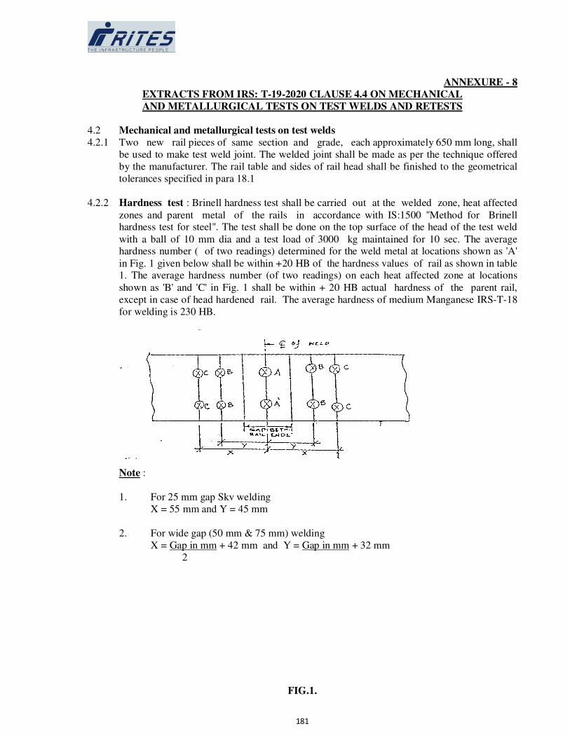
181
ANNEXURE - 8
EXTRACTS FROM IRS: T-19-2020 CLAUSE 4.4 ON MECHANICAL
AND METALLURGICAL TESTS ON TEST WELDS AND RETESTS
4.2 Mechanical and metallurgical tests on test welds
4.2.1 Two new rail pieces of same section and grade, each approximately 650 mm long, shall
be used to make test weld joint. The welded joint shall be made as per the technique offered
by the manufacturer. The rail table and sides of rail head shall be finished to the geometrical
tolerances specified in para 18.1
4.2.2 Hardness test : Brinell hardness test shall be carried out at the welded zone, heat affected
zones and parent metal of the rails in accordance with IS:1500 "Method for Brinell hardness test for steel". The test shall be done on the top surface of the head of the test weld
with a ball of 10 mm dia and a test load of 3000 kg maintained for 10 sec. The average hardness number ( of two readings) determined for the weld metal at locations shown as 'A'
in Fig. 1 given below shall be within +20 HB of the hardness values of rail as shown in table 1. The average hardness number (of two readings) on each heat affected zone at locations
shown as 'B' and 'C' in Fig. 1 shall be within + 20 HB actual hardness of the parent rail,
except in case of head hardened rail. The average hardness of medium Manganese IRS-T-18
for welding is 230 HB.
Note :
1. For 25 mm gap Skv welding
X = 55 mm and Y = 45 mm
2. For wide gap (50 mm & 75 mm) welding
X = Gap in mm + 42 mm and Y = Gap in mm + 32 mm
2
FIG.1.

182
TABLE 1
Type of rail 72 UTS rail 90 UTS rail UIC Cr-Mn or
Cr-V. Alloy
steel rail
Head
hardened rail
Average
hardness
(BHN)
230
265
310
365
4.2.3 Transverse breaking load test
4.2.3.1 The test weld shall be supported on cylindrical or semi-cylindrical supports having a
distance of one metre between them from Centre to Centre. The weld shall be at the Centre
of the span and loaded in such a manner that the foot of the rail is in tension. The diameter of
mandrel and the supports shall be between 30 to 50 mm. The load shall be gradually
increased ( rate of loading shall not exceed 2.5 t/sec) till rupture occurs.
The test weld shall withstand a minimum load and show corresponding minimum
defection as stipulated in Table 2 for different sections and types of rails.
TABLE 2
Rail type
( 1 )
Rail Section
( 2 )
Min. transverse
breaking load (t)
( 3 )
Min. deflection at the centre
at the load in col.3 (mm) ( 4 )
1. 72 UTS to IRS:T-12-
1996 -do-
2. 90 UTS to
IRS:T-12-
1996/860-0
or eqv.
52 Kg.
60 Kg.
52 Kg.
60 Kg.
85
95
90
115
18
18
15
15
4.2.3.2 If the fracture does not occur through weld slice shall be cut transversely at the weld and
etched boiling 1 : 1 hydrochloric acid for about 20 minutes determine casting defects if any.
4.2.3.3 The fractured surface of the weld, or in case while macro-etching is done on transverse section
through joint, shall not show defects such as blow holes, porosite inclusions, etc. exceeding
total permissible area of defects shown in Table 3. However, the size of any individual defect
shall not exceed 2 mm diameter. The defects should not exceed 2 mm diameter. The defects
should not be interconnected and none of these shall extend upon the outer surface of the welded There shall not be any lack of fusion. The fractured surface shall also not shown the
presence of accretions or mirror like structure and should be crystalline in acceptance.
TABLE 3
Area of permissible defects
Rail Section Permissible total area of defect (mm)
183
52 Kg.
60 Kg.
33.0
38.4
4.3 Re-tests
4.3.1 If the results of any of the tests referred to in para 4.1 and 4.2 are found to be unsatisfactory,
the batch will stand rejected. However, re-tests can be carried out at the manufacturer's
request. These re-tests shall be carried out as pera 4.1 and 4.2 on twice the original sample
size.
4.3.2 If the results of all the re-tests samples are satisfactory, the batch represented by the sample
portions shall be accepted. If any sample fails to meet the requirements of any of the tests, the
batch shall be rejected.

184

185

186
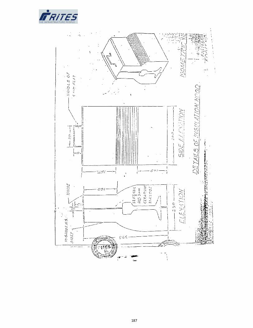
187
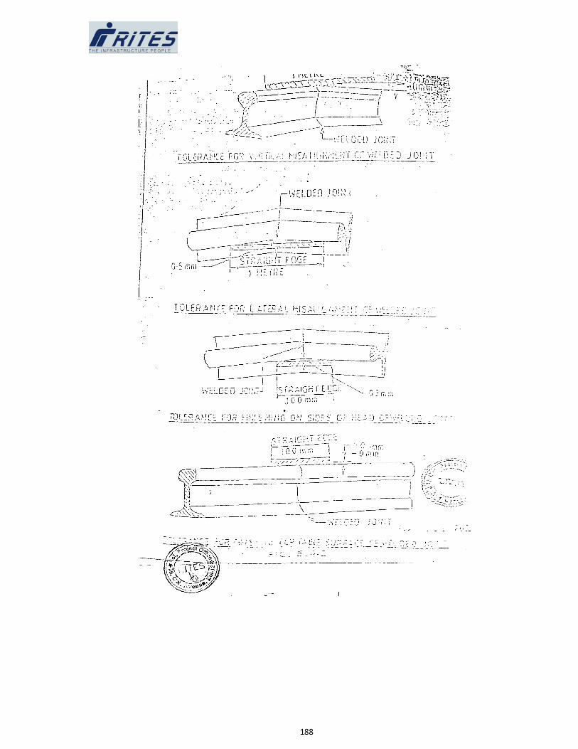
188

189
MATERIALS
DETAILED MAKE LIST & SPECIFICATION OF CIVIL ITEMS
Sl.No. Item Make
1 Brick : 1st Class brick .
2 Cement : OPC (LAFARGE , ULTRATECH , ACC , GUJRAT
AMBUJA,DALMIA , BIRLA , COROMANDEL,
BINANI , RAMCO , JAYPEE etc.).
3 Super Plasticizer : Cico,Sika, Pedilite , or equivalent & Conforming BIS.
4 Steel : TISCON, SAIL, RINL, Jindal, Shyam Steel, Electro
Steel as per RDSO latest guideline.
5 Stone Chips : Pakur variety or equivalent & Conforming BIS.
6 Sand : Conforming BIS with due approval.
7 Vitrified Tiles : Kajaria, ,Johnsons,Orient,NITCO .
10 Ceramic Tiles : Kajaria, ,Johnsons,Orient,NITCO .
11 Acid,alkali resistant tiles : Conforming BIS with due approval.
12 Granite : Black Granite or any approved colour..
13 Sal Wood : Malayasian Sal Wood.
14 Chequered tiles PoddarTiles,UNISTONE,HINDUSTAN TILES or
equivalent & Conforming BIS.
15
Zn-Al alloy coating roof
sheet
: Tata Bluescope, or equivalent & Conforming BIS .
16 Waterproofing : Sika,FOSROC,PIDILITE,DR FIXIT or equivalent &
Conforming BIS.
17 Structural Steel TISCON,SAIL,RINL,JINDAL, or equivalent &
Conforming BIS.
18 MS Grill : Conforming BIS.
19 Stainless steel railing : Conforming BIS.
20 Woodwork : Malaysian Sal
21 Door fittings & fixtures : Conforming BIS.
22 Putty : JK White,Berger or equivalent & Conforming BIS.
23 Paint,Distemper : Asian,ICI,Berger, Nerolac or equivalent & Conforming
BIS.
24 Water proofing cement
paint
: ICI,Nerolac,Snowcem India or equivalent &
Conforming BIS.
25 UPVC,CPVC -
pipes,fittings
: Ashivad,Astral,Supreme or equivalent & Conforming
BIS.
26 Aluminium sections : Hindalco,Century,Jindal or equivalent & Conforming BIS.
27 GI pipes : JIndal,TATA,Sail or equivalent & Conforming BIS.
28 GI fittings : Conforming BIS.
29 Plumbing fittings,PTMT : Prayag or equivalent & Conforming BIS.
30 Vitreous China Sanitary
ware
: Parryware, Hindware,Cera or equivalent &
Conforming BIS.
31 WC seats & covers : Parryware,Hindware,Johnson,Commander or
equivalent & Conforming BIS.
32 Mirror : Saint Gobain,Atul, Modifloat, or equivalent &
Conforming BIS.
33 Glazing : Float glass of Saint Gobain,Modiguard, Asahi
IndiaSafety Glass or equivalent & Conforming BIS.
34 Hydraulic Door Closer : Hardwyn,Everite,Garnish or equivalent & Conforming

190
BIS.
35 RCC pipes : Indian Hume pipe,Spun pipe co,Pragati Concrete
Udyog or equivalent & Conforming BIS.
36 Polythelene water storage
tank
: Sintex,Paton,Rotex,Rotomac Plus or equivalent &
Conforming BIS.
37 Flush Door : Century ,GreenPly,Tycoonor equivalent & Conforming
BIS.
38 Sewege Pipe : Supreme, Astral or equivalent & Conforming BIS.
39 Stainless steel sinks : Neerali,Neelkanth,Prestige,AMC,Kingston or
equivalent & Conforming BIS.
40 Manhole covers : KK,SK precast concrete,Daya concrete or equivalent &
Conforming BIS.
B ANY ITEM NOT
MENTIONED ABOVE
: Conforming BIS with due approval.
(Any other brand which are not listed above, will be operated as per direction/approval of Engineer-In-
Change)
Related Documents