1 RIT-μX - The New Modular High Precision Micro Ion Propulsion System Hans Leiter 1 and Rainer Killinger. 2 Astrium GmbH BL Equipment and Propulsion, P.O. 1119, 74215 Möckmühl, Germany Michael Boss 3 , Michael Braeg 4 and Matthias Gollor 5 Astrium Satellites GmbH, 88039 Friedrichshafen, Germany Stefan Weis 6 and Davar Feili 7 University of Gießen, Heinrich Buff Ring 16, 35392 Gießen, Germany Michael Tartz 8 and Horst Neumann 9 IOM Leipzig, Permoserstr. 15, 04318 Leipzig Germany Jens Haderspeck 10 and Dagmar Bock 11 IRS Stuttgart Pfaffenwaldring31, 70569 Stuttgart, Germany and Davina Maria Di Cara 12 ESA ESTEC, Keplerlaan 1, 2201 AZ Noordwijk, The Netherlands RIT-μX is a radio frequency ion engine for micro propulsion applications. The ionization of the propellant by electro magnetic fields offers inherently highest thrust control, -stability and resolution. The function principle of the engine and the specific advantages are explained and the layout of a propulsion system is presented. Challenges for system design are the selection and development of appropriate electronics, neutralization and Xenon flow management. Principle approaches are provided and discussed. I. Introduction ini ion engines are considered as suitable solution to overcome difficulties and limitations of existing propulsion concepts for low and lowest thrust application. A crowing number of missions combines the demand for high specific impulse, long lifetime, high total impulse and last but not least highest thrust resolution, accuracy and controllability. Reducing the altitude of earth observing satellites in low earth orbits evidently increases the resolution of the data from the measuring instrumentation. On the other hand the atmosphere's influence on the spacecraft increases. A compensation of the atmospheric drag becomes mandatory. This is challenging for the propulsion system, as high 1 Development Electric Propulsion, TP 42, [email protected]. 2 Head of TP 42 Electric Propulsion, TP 42, [email protected] 3 Business Development, Dept. Electronics Equipment G. & Solar Generators, [email protected] 4 Dept. Electronics Equipment G. & Solar Generators, [email protected] 5 Consultant and Professor at the University of Applied Science Konstanz: e-mail [email protected] 6 1st Institute of Physics [email protected] 7 1st Institute of Physics [email protected] 8 Senior Researcher [email protected] 9 HoG [email protected] 10 Institute for Raumfahrtsysteme [email protected] and [email protected] 11 Institute for Raumfahrtsysteme [email protected] 12 TOS/MPE, [email protected] M

Welcome message from author
This document is posted to help you gain knowledge. Please leave a comment to let me know what you think about it! Share it to your friends and learn new things together.
Transcript

1
RIT-µX - The New Modular High Precision Micro Ion
Propulsion System
Hans Leiter1 and Rainer Killinger.
2
Astrium GmbH BL Equipment and Propulsion, P.O. 1119, 74215 Möckmühl, Germany
Michael Boss3, Michael Braeg
4 and Matthias Gollor
5
Astrium Satellites GmbH, 88039 Friedrichshafen, Germany
Stefan Weis6 and Davar Feili
7
University of Gießen, Heinrich Buff Ring 16, 35392 Gießen, Germany
Michael Tartz8 and Horst Neumann
9
IOM Leipzig, Permoserstr. 15, 04318 Leipzig Germany
Jens Haderspeck10
and Dagmar Bock11
IRS Stuttgart Pfaffenwaldring31, 70569 Stuttgart, Germany
and
Davina Maria Di Cara12
ESA ESTEC, Keplerlaan 1, 2201 AZ Noordwijk, The Netherlands
RIT-µX is a radio frequency ion engine for micro propulsion applications. The ionization
of the propellant by electro magnetic fields offers inherently highest thrust control, -stability
and resolution. The function principle of the engine and the specific advantages are
explained and the layout of a propulsion system is presented. Challenges for system design
are the selection and development of appropriate electronics, neutralization and Xenon flow
management. Principle approaches are provided and discussed.
I. Introduction
ini ion engines are considered as suitable solution to overcome difficulties and limitations of existing
propulsion concepts for low and lowest thrust application. A crowing number of missions combines the
demand for high specific impulse, long lifetime, high total impulse and last but not least highest thrust resolution,
accuracy and controllability.
Reducing the altitude of earth observing satellites in low earth orbits evidently increases the resolution of the
data from the measuring instrumentation. On the other hand the atmosphere's influence on the spacecraft increases.
A compensation of the atmospheric drag becomes mandatory. This is challenging for the propulsion system, as high
1 Development Electric Propulsion, TP 42, [email protected].
2 Head of TP 42 Electric Propulsion, TP 42, [email protected]
3 Business Development, Dept. Electronics Equipment G. & Solar Generators, [email protected]
4 Dept. Electronics Equipment G. & Solar Generators, [email protected]
5 Consultant and Professor at the University of Applied Science Konstanz: e-mail [email protected]
6 1st Institute of Physics [email protected]
7 1st Institute of Physics [email protected]
8 Senior Researcher [email protected]
9 HoG [email protected]
10 Institute for Raumfahrtsysteme [email protected] and [email protected]
11 Institute for Raumfahrtsysteme [email protected]
12 TOS/MPE, [email protected]
M
2
thrust controllability and resolution is required combined with sufficient total impulse. Moreover the high amount of
atomic Oxygen requires a robustness of the engine against this aggressive element. Concerns with respect to any
technology which requires (hot) cathodes exists.
The installation of formation flying satellites forming one large virtual instrument offering a significant higher
resolution than any large single instrument is considered as a break through for several types of (deep) space
observation missions. Such experiments will deliver important impacts for fundamental physics and our
understanding of the universe. For these formations again the controllability and the thrust resolution are from
importance. High specific impulse and total impulse are highly desirable to maintain the experiments over years.
Ultra fine thrust control is required for some missions dealing with the measurement of gravity waves. Goal is a
propulsion system with a thrust starting with zero to some tenth (hundreds) of micro Newtons. As these experiments
will take place far from Earth, for example at the Lagrangian point L2 also a higher thrust in the range of some milli
Newtons for the cruise phase to the destination is required.
The strong need for micro-propulsion is identified by the scientific community, industry and the space agencies.
Astrium's micro propulsion solution is called RIT-µX. The name "RIT-µX" follows Astrium's convention to label
the Radio Frequency Ion Thrusters with an X as long as the thruster is in an early development status (see RIT-XT
and RIT-22). The Greek "µ" emphasizes the special abilities of the engine for micro propulsion.
The work presented in this publication is performed under a contract granted by the European Space Agency
ESA in the frame of the GSTP programs. Under lead of Astrium, Business Line "Equipment and Propulsion" a study
and development team has been formed bringing together the competences in all relevant fields. Astrium is a well
known system house with a long term heritage in electric propulsion. For more than 3 decades a fruitful co-operation
with Giessen University exists. The Radio Frequency principle was invented in Giessen in the early sixties of the
last century by professor Horst.W. Loeb, later-on a whole family of ion engine prototypes was developed under his
lead[ 8][ 9] [ 10].
During the last 3 years Giessen University has focused its activities on micro-propulsion [3]. The successful
work has been the basis for the activities described here. Naturally, Giessen University is a strong partner in this
project. Giessen University provides knowledge of thruster physics, scaling and layout. Moreover Giessen provides
test services for development and endurance testing. Another experienced long-term partner in RIT development is
the Institute for Surface Modification (IOM) Leipzig. The IOM has the lead for ion optics and lifetime analysis.
Although hardware activities are limited to the ion engine itself the RIT-µX project comprises system
engineering too. An essential part for any ion engine is the required power supply and control logic (PSCU).
Elaboration of the electronics system is performed by Astrium Satellites GmbH (Friedrichshafen). Design and layout
of the flow management system is supported by University of Stuttgart, Institute for Space Systems (IRS).
II. Micro Propulsion Missions and Requirements
A. Missions
''The use of electric propulsion is now commonly recognised within ESA for application on Telecommunication
Satellites (ARTEMIS, ALPHABUS), Scientific Spacecraft (SMART1, BepiColombo and LISA Pathfinder) and
Earth Observation Missions (GOCE). Over the last few years another emerging market has been recognised which implement a distributed spacecraft to
improve instrument resolution. In order to achieve adequate signal reconstruction, this application requires close
control of the spacecraft separation and attitude through formation flying. This typically implies fine thrust control
of the order of µN. Moreover, in order to reduce the time for re-pointing manoeuvres higher thrust levels of the order
of mN are beneficial. The ESA Science Directorate has recently issued a call for future scientific missions, Cosmic Vision 2015-2025.
Two of the candidate astrophysics missions are formation flying observatories, DARWIN and XEUS. ESA is currently preparing in the frame of the GST-Programme the formation flying technologies and techniques
which will be proven within the ESA PROBA3 project, the first Agency Formation Flying Technology
Demonstration mission. PROBA 3 will be used also as test bench for micro-propulsion systems in order to verify
3
compliance to the specific propulsion and control needs of formation flying applications.
B. Requirements for micro propulsion Based on the on-going studies on the above described application, the critical performance requirements
identified for a micro-propulsion system include high specific impulse, precise thrust modulation in the µN to low
mN range, very precise thrust level resolution and response rate. A preliminary set of requirements is summarized in
Table 1
Moreover the design of the propulsion system needs to comply with the need of those spacecraft to perform full
3-axis (6DoF) attitude control, with their limitation in mass, volume and power availability and with the very high
total impulse required.
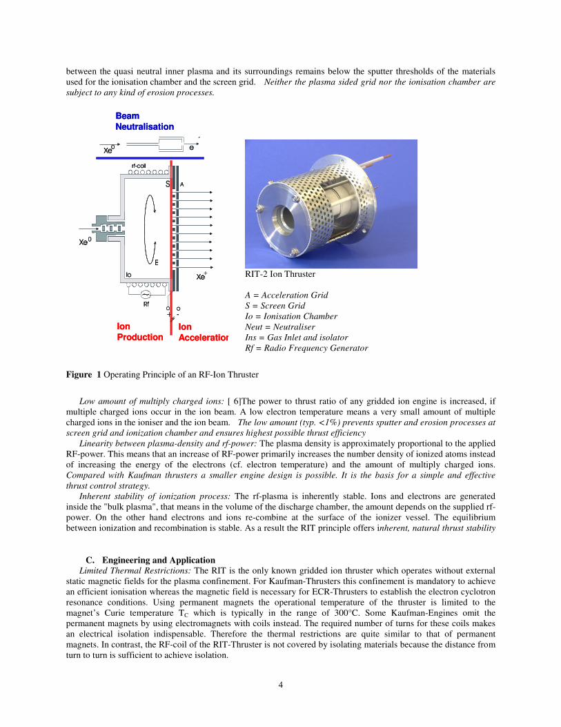
Thrust range (fine) (1) 5µN-150µN
Thrust range (coarse), (3) 200µN-4mN
Thrust resolution ~0.1 µN
Thrust noise, ~0.1µN/ � Hz for thrusts under
150 µN
Thrust regulation capability <0.5 µN At least 0.7% full range
Thrust response time <10mS
Total Impulse
Fine:
Course
<1400Ns tbc @ 30 µN
< 40kNs @ 3000µN
Table 1 Summary of preliminary requirements for RIT-µX ion engine development.
III. The RIT-µX Ion Propulsion System
A. RIT-µX Basics
Heart of the new RIT-µX small ion propulsion system is the radio frequency ion thruster RIT-µX with the
unique electrodeless ionization of the propellant by electromagnetic waves. RF-ionization is known as a very
effective way to ionise neutral gases. The implementation of this ionisation principle is very simple as merely two
components are necessary: An ionisation chamber made of an isolating material and an RF-coil which surrounds
this chamber. No other parts are required inside or outside the ioniser with respect to ionisation of the propellant!
This makes the overall concept very simple, robust and erosion free.
If an RF-current is applied to the the thrusters RF-coil a primary axial magnetic field is induced inside the
ioniser. This field generates a secondary circular electric field (E). Whereas the effect of this electro-magnetic field
on neutrals or ions is negligible, free electrons gain sufficient energy for impact ionisation of the propellant: The
propellant is set into the plasma state. Once the ionisation process is initially triggered the process is self-sustaining.
All electrons required for a steady state operation are generated in the discharge itself. There is no need for an
additional electron source, e.g. a main cathode, inside the ionisation chamber.
In ion thruster technology the rf-principle is unique, but there exists a broad field of applications where rf-
ionization is used. It is employed in plasma- and ion sources for material processing (solid state physics,
semiconductors, plasma chemistry…) as well as for neutral injector sources for fusion plasma heating. So the
physics behind are well understood. Some special properties, which also apply for ion thrusters, make the RF-
plasma very favourable for propulsion purposes and especially for micro propulsion.
B. Physical Background High Discharge Efficiency: The plasma generation by RF is one of the most efficient methods to set a gas in the
ionized plasma state. The efficiency is so high that no additional support, like external magnetic fields for plasma
confinement is required. RF-thrusters work without permanent magnets or additional solenoid.
Low Electron Temperature: [ 6][ 7]The plasma’s electron temperature is comparably lower than for Kaufman
thrusters. Therefore the potential drop, which in a first order is directly proportional to the electron temperature,
4
between the quasi neutral inner plasma and its surroundings remains below the sputter thresholds of the materials
used for the ionisation chamber and the screen grid. Neither the plasma sided grid nor the ionisation chamber are
subject to any kind of erosion processes.
Beam
Neutralisation
Ion
Acceleration
Ion
Production
Beam
Neutralisation
Ion
Acceleration
Ion
Production
RIT-2 Ion Thruster
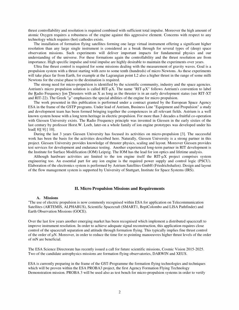
A = Acceleration Grid
S = Screen Grid
Io = Ionisation Chamber
Neut = Neutraliser
Ins = Gas Inlet and isolator
Rf = Radio Frequency Generator
Figure 1 Operating Principle of an RF-Ion Thruster
Low amount of multiply charged ions: [ 6]The power to thrust ratio of any gridded ion engine is increased, if
multiple charged ions occur in the ion beam. A low electron temperature means a very small amount of multiple
charged ions in the ioniser and the ion beam. The low amount (typ. <1%) prevents sputter and erosion processes at
screen grid and ionization chamber and ensures highest possible thrust efficiency
Linearity between plasma-density and rf-power: The plasma density is approximately proportional to the applied
RF-power. This means that an increase of RF-power primarily increases the number density of ionized atoms instead
of increasing the energy of the electrons (cf. electron temperature) and the amount of multiply charged ions.
Compared with Kaufman thrusters a smaller engine design is possible. It is the basis for a simple and effective
thrust control strategy.
Inherent stability of ionization process: The rf-plasma is inherently stable. Ions and electrons are generated
inside the "bulk plasma", that means in the volume of the discharge chamber, the amount depends on the supplied rf-
power. On the other hand electrons and ions re-combine at the surface of the ionizer vessel. The equilibrium
between ionization and recombination is stable. As a result the RIT principle offers inherent, natural thrust stability
C. Engineering and Application
Limited Thermal Restrictions: The RIT is the only known gridded ion thruster which operates without external
static magnetic fields for the plasma confinement. For Kaufman-Thrusters this confinement is mandatory to achieve
an efficient ionisation whereas the magnetic field is necessary for ECR-Thrusters to establish the electron cyclotron
resonance conditions. Using permanent magnets the operational temperature of the thruster is limited to the
magnet’s Curie temperature TC which is typically in the range of 300°C. Some Kaufman-Engines omit the
permanent magnets by using electromagnets with coils instead. The required number of turns for these coils makes
an electrical isolation indispensable. Therefore the thermal restrictions are quite similar to that of permanent
magnets. In contrast, the RF-coil of the RIT-Thruster is not covered by isolating materials because the distance from
turn to turn is sufficient to achieve isolation.
5
RIT µX Thruster Unit (TU)
=
RIT 22 Thruster (T)
+
Radiofrequency Generator (RFG)
+
? Neutralizer (NTR) ?
Power Supply&ControlUnit (PSCU/PPU…)
Positive High Voltage
Negative High Voltage
RFG Voltage
NTR Voltage
Control-Logic+IF
Power Supply&ControlUnit (PSCU/PPU…)
Positive High Voltage
Negative High Voltage
RFG Voltage
NTR Voltage
Control-Logic+IF
Flow Control Unit (FCU)Flow Control Unit (FCU)
RIT-µX IPSRIT-µX IPS
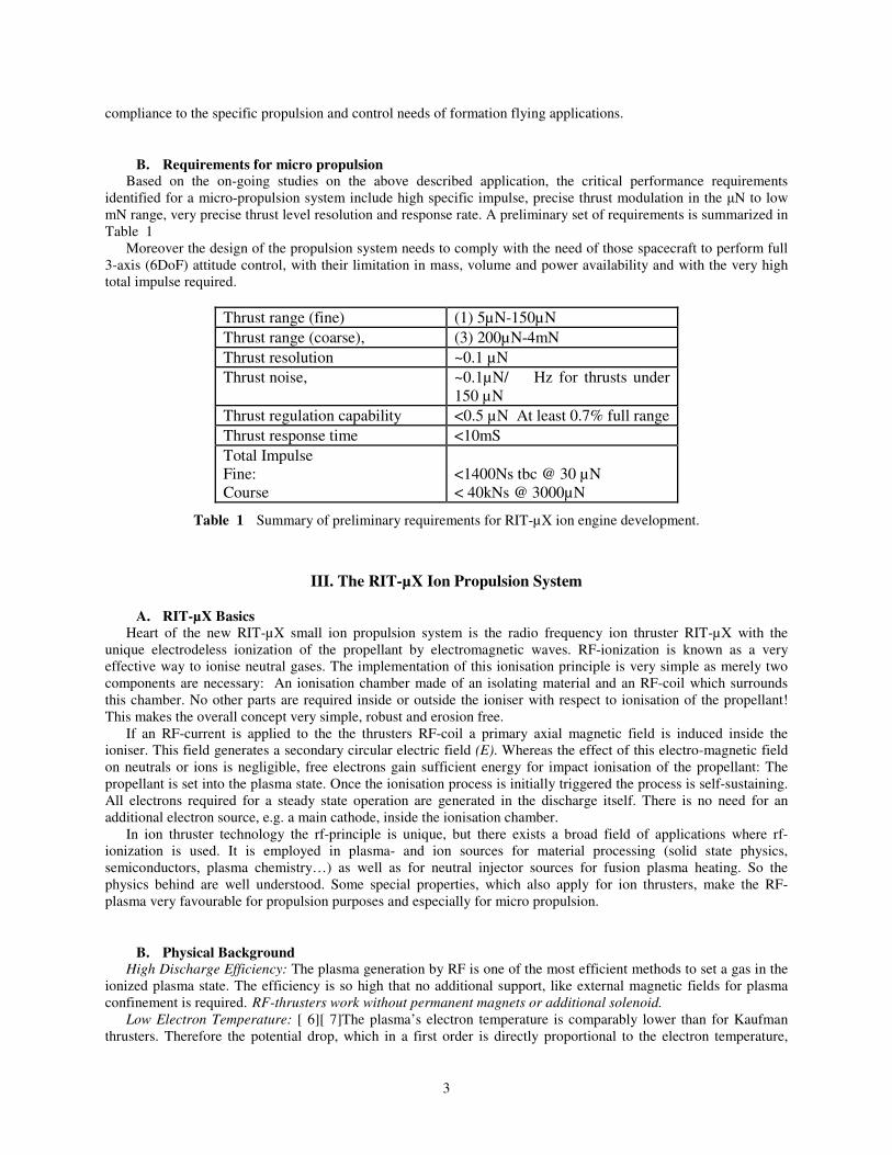
Figure 2 Generic RIT-µX IP System Layout
Inherent High Voltage Isolation: The ionized propellant (plasma) is an excellent electrical conductor. So the
high voltage provided to the screen grid (or an anode) is "visible" for any component in contact with the plasma. In
case of the RIT this voltage is inherently isolated from surroundings. The non-conductive ionizer vessel is a natural
barrier. In a RIT system only the cabling to the grid is on high voltage potential. In Kaufman engines also the entire
cathode system and the anode are on high potential. Special care is required, also for the layout of the PPU where
several modules are on high voltage potential.
Thrust control: The clear relationship between applied RF-power and extractable ion current and the inherent
stability of the ionisation offer an effective thrust control strategy. Also without any regulation the beam current is
constant as long as no other operational parameters alter (e.g. mass flow). For example, stability better than 0.3%
over 100h was multiply demonstrated with the large RIT-22 engine. During this test no active thrust regulation was
employed. With a simple closed loop between ion beam and RF-supply a high precision thrust control is realized.
The stability only depends on the accuracy of the employed electronics. Neither external magnetic fields have to be
controlled nor does any restriction by additional fields apply. Using high precision laboratory power supplies and the
closed loop concept the thrust stability achieved with RIT-22 is better than 0.1‰ (+/- 1mA @ 2380mA beam current)
Ultra Fast Thrust Control: If the rf-power is varied the ionization responses to a new equilibrium within some
rf-periods. So within a few microseconds the thrust reaches a new state. The time thrust resolution of the overall
propulsion system depends on the speed of the electronics around the engine. It is not limited by the thruster itself.
In contrast to the rf-ionization any engines requiring cathodes are limited in there response by the thermal capacity
of the cathode.
Thrust noise: The inherent thrust stability in combination with the fast thrust response offers excellent low thrust
noise. The extreme low thrust noise is a challenge for any measurement.
D. Generic RIT-µX System
A RIT µX ion engine requires propellant and
electricity for operation. The propellant flow to
the engine and the neutralizer is controlled by a
flow control unit (FCU), the required electric
power is provided by the power processing unit
(PPU). Beside the thruster unit the PPU controls
also the FCU.
A system consisting of the thruster unit, the
power processing unit and the flow control unit is
called "Radio Frequency Ion Thruster Assembly -
RITA". Function and tasks of all RITA
components are explained in the following
section.
IV. System Aspects
A. First elaborated RIT-µX Electronics System
The availability of suitable electronics is a key factor for the RIT-µX Ion Propulsion System (IPS). As the
thruster physics ensure highest thrust stability, ultra fast thrust response and high thrust resolution the system
performance is driven by far more by the engine's electronics than by the thruster itself. When the engine is operated
with a beam voltage of 900V a beam current of 1mA is corresponding to a thrust of 5µN. It means the operational
range of the electronics for the RIT-µX is very different in terms of current and power from previously developed
electronics for engines like RIT-10 and RIT-22.
Another principle difference is the number of engines to be operates simultaneously. For north-south-station
keeping, typically only one engine is operated. For extended orbital maneuvers (orbit toping etc.) the operation of
two engines is considered. A similar picture is shown considering interplanetary probes. Typically, one or two
engines are operated at the same time.
For a mini ion engine system the situation is different. The system shall provide full 6-axis control. Taking into
account all circumstances, systems operating up to eight thrusters simultaneously are under discussion. As the
system studies are not finalized and the demands might differ from mission to mission a flexible modular approach
is required. The answer is a modular scalable Power Supply and Control Unit (PSCU).

6
For each engine the following elements are required:
• Positive High Voltage Supply (PHV)
• Negative High Voltage Supply (NHV)
• Hardware Beam Current Controller including Beam Current Sensor, Beam Current Reference, Regulator
• Power Supply for the Radio-Frequency Generator
In addition the PSCU has to provide the interfaces to the spacecraft's power and data bus. The PSCU has to
control also the Flow Control System and the neutralization.
Figure 3 Principle Layout of a Power Supply and Control Logic for a RIT-µX Ion Engine System.
B. Neutralization
As any other gridded ion thruster RIT-µX expels positively charged ions only through its grid system.
Consequently a source of negative charges is required in order to compensate the ion current. Different technologies
are available with specific pros and cons.
Plasma bridge neutralizer:
This is the classical device as used today for larger ion engines. An inert gas (typ. Xenon), flows into the cathode
chamber where it is ionised by electrons emitted from an insert (made of porous tungsten for example, impregnated
with chemicals to reduce the work function for electron extraction). The insert is brought to termionic emission
7
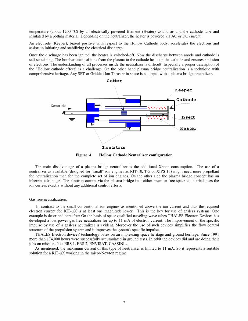
temperature (about 1200 °C) by an electrically powered filament (Heater) wound around the cathode tube and
insulated by a potting material. Depending on the neutralizer, the heater is powered via AC or DC current.
An electrode (Keeper), biased positive with respect to the Hollow Cathode body, accelerates the electrons and
assists in initiating and stabilizing the electrical discharge.
Once the discharge has been ignited, the heater is switched-off. Now the discharge between anode and cathode is
self sustaining. The bombardment of ions from the plasma to the cathode heats up the cathode and ensures emission
of electrons. The understanding of all processes inside the neutralizer is difficult. Especially a proper description of
the "Hollow cathode effect" is a challenge. On the other hand plasma bridge neutralization is a technique with
comprehensive heritage. Any SPT or Gridded Ion Thruster in space is equipped with a plasma bridge neutralizer.
Keeper
Insert
Cathode
H eater
Xenon inlet
Getter
Insulators
Figure 4 Hollow Cathode Neutralizer configuration
The main disadvantage of a plasma bridge neutralizer is the additional Xenon consumption. The use of a
neutralizer as available (designed for "small" ion engines as RIT-10, T-5 or XIPS 13) might need more propellant
for neutralization than for the complete set of ion engines. On the other side the plasma bridge concept has an
inherent advantage: The electron current via the plasma bridge into either beam or free space counterbalances the
ion current exactly without any additional control efforts.
Gas free neutralization:
In contrast to the small conventional ion engines as mentioned above the ion current and thus the required
electron current for RIT-µX is at least one magnitude lower. This is the key for use of gasless systems. One
example is described hereafter: On the basis of space qualified traveling wave tubes THALES Electron Devices has
developed a low power gas free neutralizer for up to 11 mA of electron current. The improvement of the specific
impulse by use of a gasless neutralizer is evident. Moreover the use of such devices simplifies the flow control
structure of the propulsion system and it improves the system's specific impulse.
THALES Electron devices' technology bases on an impressing space heritage and ground heritage. Since 1991
more than 174,000 hours were successfully accumulated in ground tests. In orbit the devices did and are doing their
jobs on missions like ERS 1, ERS 2, ENVISAT, CASSINI….
As mentioned, the maximum current of this type of neutralizer is limited to 11 mA. So it represents a suitable
solution for a RIT-µX working in the micro-Newton regime.

8
Figure 5 Emission characteristics of gas free cathode developed by Thales Electron Devices.
RF sources as neutralizer:
Availability of classic plasma bridge neutralizers as well as gasless systems ensure that there will not be any
deadlock for the further RIT-µX development and most probably one of these two options will be selected, but it is
worth to mention a third option.
Although the plasma bridge neutralizer and the gasless Thales system are working fine on ground on and in
space they have a common disadvantage: The cathodes are very sensitive against contamination by humidity and
oxygen. In worst case a contamination leads to a full loss of function. So, special care is required during storage,
handling and operation of the neutralizers. Another concern is the process of ground verification onboard the
complete spacecraft: For operation high vacuum conditions are mandatory.
The sensitivity against ATOX might become a strict show stopper for missions in low and lowest Earth Orbit.
The high amount of atomic oxygen might reduce the system lifetime drastically.
Following the rf-principle of the RIT-technology the idea of an 'RF electron source' was born. The ionization is
similar to an RF- thruster. Instead of ions electrons are extracted from the discharge plasma. This technology is
cathode free. Under research contracts of the German Space Agency, these types of electron sources are under
development at the 1st Institute of Physics of Giessen University and the IOM Leipzig.
C. Flow Control Management
A real challenge for the development of an RIT-µX system is the Xenon management. The use of an
conventional Flow control systems is not satisfying mainly for three reasons:
• The mass of the required valves is high compared with the mass of a RIT-µX ion engine
• The power consumption of conventional valves compared with the total system is high too
• Open and close of the valves might introduce additional momentum to the spacecraft. For most
application this aspect is negligible, but for some advanced scientific missions intended to investigate
extremely small forces it might be relevant.
In the following, the design of a traditional flow control system is described and the tasks of the system are
derived. This is the point to start over with advanced concepts.
The Xenon feed system represents the interface between Xenon tank and ion engine. It reduces the high pressure
at the tank to an adequate level and it controls on of the engine's key parameters, the Xenon mass flow. The
accurate control of the Xenon flow is mandatory to ensuring engine operation with maximum specific impulse and
minimized grid erosion. The Xenon feed system consists of fill and drain valves, isolation valves, filters, tubing and
the pressure and flow control system.
Gun emission
0
2
4
6
8
10
12
14
-5 0 5 10 15 20 25 30
Grid Voltage / V
Em
issio
n C
urr
en
t /
mA
9
Classical pressure and flow control systems have dual stage architecture: a pressure regulating stage feeds the
propellant into a flow restrictor downstream. As electric propulsion gains currency, the xenon feed systems are
evolving but the dual stage architecture is remaining.
The pressure control stage is typically either a mechanical or an electrical pressure regulator and the flow control
stage contains a fixed restrictor, a proportional valve or a thermal restrictor.
Pressure Control Stage
Pulsed Valve Regulation System
The Pulsed Valve Regulation System (Bang-Bang) is a simple electronic pressure regulator. It includes the use
of a solenoid valve in conjunction with an accumulator tank (plenum). The solenoid valve is the “regulator” in the
system and the plenum reduces the pressure spikes and smoothes oscillation. Nevertheless the resulting flow
characteristic is a saw tooth (e.g. Moog Model 51E186 (200g)) [2].
Proportional Valve
Evolved from the Pulsed Valve Regulation System, the proportional valves offer a compacter design and a faster
response time. There are plenty of different valves available which differ among others in the type of actuator used.
Designs base on magnet- restriction, proportional solenoids, piezo effect and squeezed flexible tube exist.
Flow Control Stage
Proportional Valve
A typical flow regulation method is the use of a valve. The flow rate varies as the distance between a valve seat
and a valve cap is changed [ 12.
Fixed Restrictor
Fixed restrictors like an orifice, a capillary or a tube with build-in wire are throttling the flow depending on the
attached pressure and temperature. Flow control is achieved by regulating the system pressure upstream of the
restrictor, which responses with a specified flow rate at a given pressure and temperature.
Thermal Restrictor
Controlling the flow via a Thermal Restrictor is a very simple technique used for fine control. Gaseous xenon is
directed through a capillary which is in contact with a heater. An increasing gas temperature leads to an increasing
viscosity and a decreasing density. Therewith the mass flow declines and the achievable turn down ratio is around
1:5 (e.g. Marotta UK Capillary Thermal Flow Controller (20g)) [ 12]. The effect of thermal expansion is negligible
with the use of a capillary. While on the contrary flow through an annular gap with a sufficient radius uses the
thermal expansion in addition to the change in density and viscosity (e.g. Marotta Thermal Throttle(11g)). The flow
turn down ratio coming along with this design is infinite.
Integrated Pressure and Flow Control System
As mentioned before a complete AOCS system consists of numerous engines, up to 8 in the case of 6-DoF
operation, not counting the redundant ones. To prevent unnecessary grid erosion and loss of specific impulse each
RIT-µX demands for separate control of the Xenon flow. Using conventional components leads to a heavy and
power consumptive flow control unit. Both, mass and power demand can be significantly reduced by use of fully
integrated miniaturized design. Savings in the order of a magnitude seem feasible. [ 14].
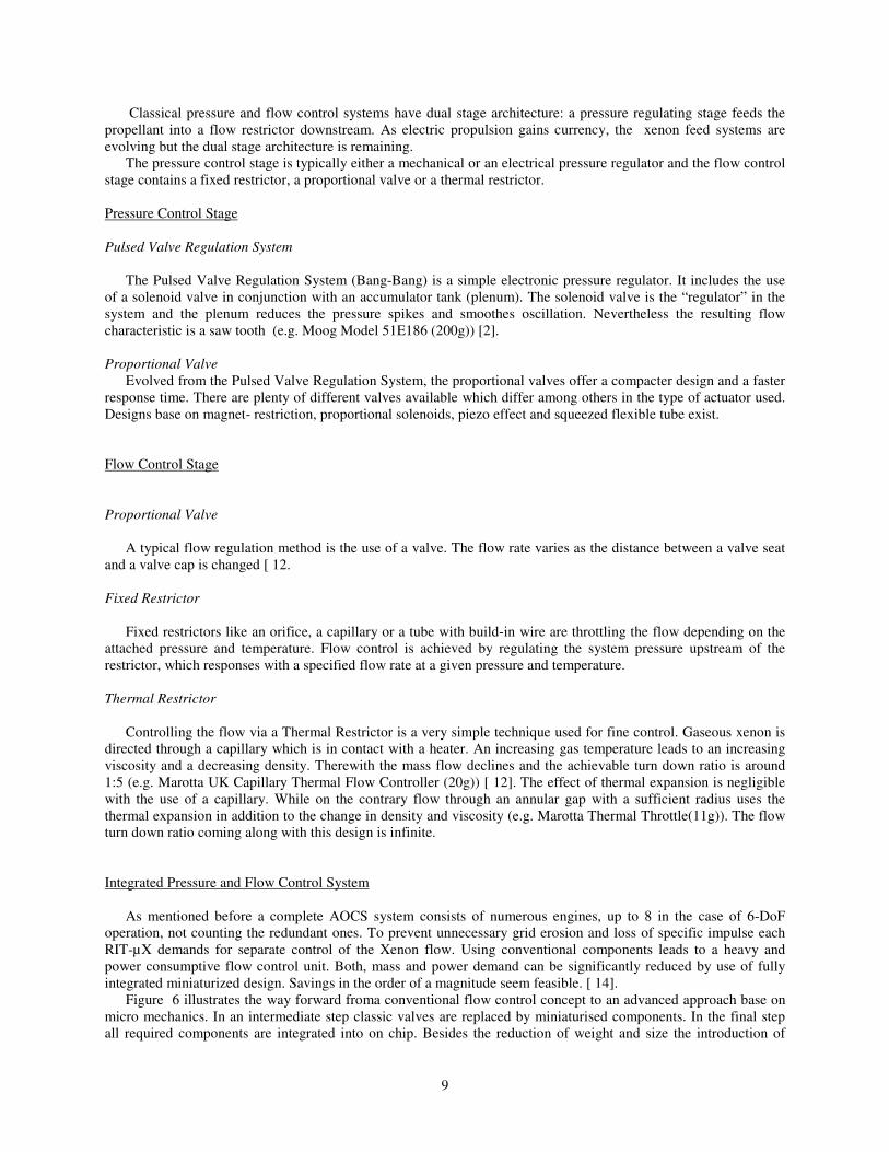
Figure 6 illustrates the way forward froma conventional flow control concept to an advanced approach base on
micro mechanics. In an intermediate step classic valves are replaced by miniaturised components. In the final step
all required components are integrated into on chip. Besides the reduction of weight and size the introduction of
10
micro structures might lead to a significant cost reduction. NanoSpace is one of the European companies working in
the field of Micro Electro Mechanical System based (MEMS) xenon feed systems: Silicon wafers are stacked
together in a modular building concept. The different wafer stacks contain several components and functions such as
isolation valves, filters, flow control valves, and thermal flow restrictors. The feed system uses a flow regulation
valve for coarse tuning. In addition, fine tuning is achieved by a thermally-actuated flow restrictor. The fine tuning
modulation is in the order of 25-30% at constant inlet pressure [ 14].
A similar system is under development at Thales Alenia Space (Florence, Italy)
Figure 6 Schematics of a generic xenon feed system using discrete components, schematics of the xenon feed
system based on Micro Mechanical Xenon Feed System by Nanospace and schematics of the next integrated xenon
feed system (from left to right) [ 14].
Eurostar 3000 Artemis SMART-1 MEMS Integrated
Xenon Feed system
Pressure stage mass 5,62 kg 2,8 kg
Flow control unit mass 4 x 0,58 kg 4 x 2 kg 8 kg 0,8 kg
Total mass of XFS 7,94 kg 10,8 kg 8 kg 0,8 kg
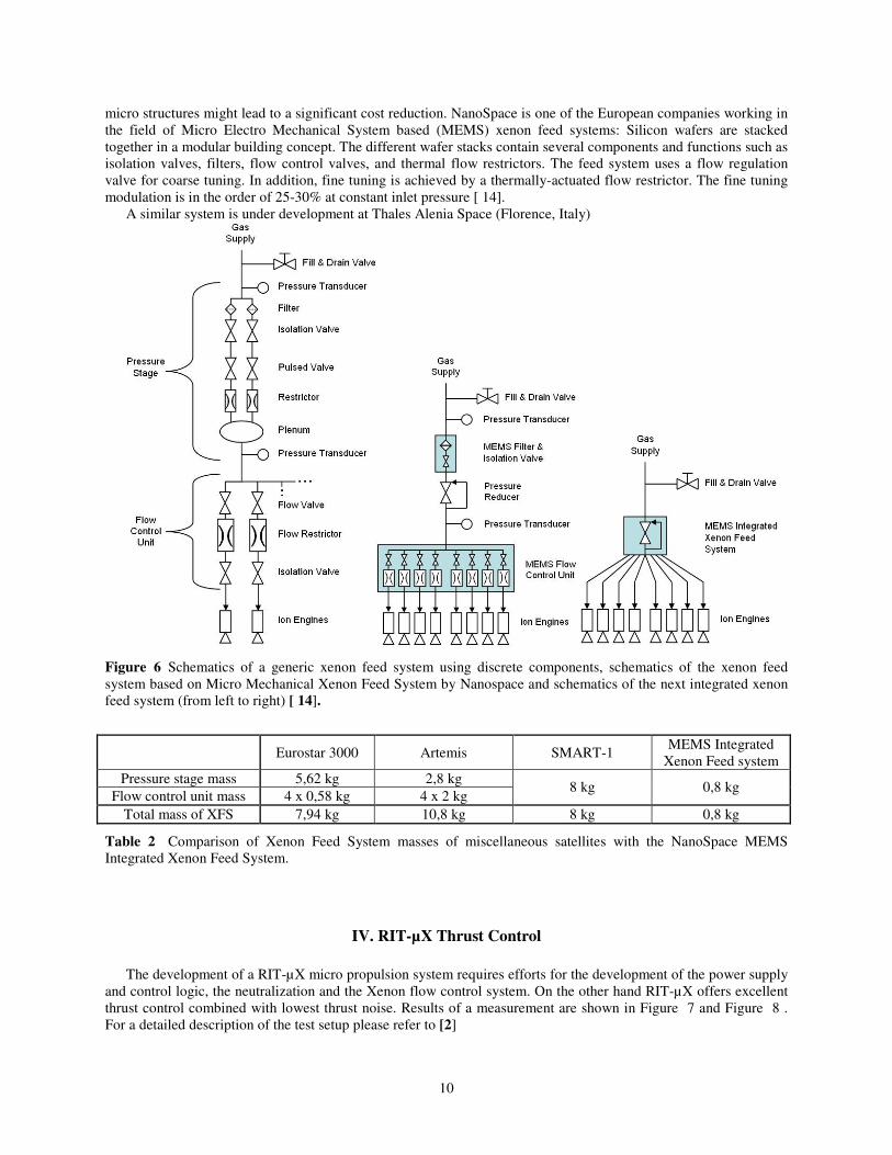
Table 2 Comparison of Xenon Feed System masses of miscellaneous satellites with the NanoSpace MEMS
Integrated Xenon Feed System.
IV. RIT-µX Thrust Control
The development of a RIT-µX micro propulsion system requires efforts for the development of the power supply
and control logic, the neutralization and the Xenon flow control system. On the other hand RIT-µX offers excellent
thrust control combined with lowest thrust noise. Results of a measurement are shown in Figure 7 and Figure 8 .
For a detailed description of the test setup please refer to [2]

11
The thruster was operated at a constant thrust level using the stabilization of the BCC device. As any RIT allows
a trade-off , power versus mass efficiency, a high mass efficiency has been selected to reach an ISP of 2700s.
The beam current has been sampled over a period of about 10 hours at a data acquisition rate of 50Hz
(integrating) and finally the equivalent thrust was calculated.
As displayed in Figure 7, the thrust is very constant over the measured period. The typical noise is in a band of
10nN, but it seems there is also an amount of spikes of higher amplitude. For a better understanding of these spikes a
histogram of the thrust values of the full dataset has been compiled. Figure 8 shows the frequency of the
measurement of a specific thrust level. In contrast to the thrust versus time plot the histogram clearly indicates, that
the above-mentioned spikes are rare in occurrence. The optical impression of the simple thrust vs. time plot is
misleading. The standard deviation of the thrust is only 2.3nN. Although the spikes seem high compared to the
average noise all of them are covered in a band of less than 0.1µN. This demonstrates the potential of the RIT
technology to provide reliably a very constant thrust even over long periods and at low thrust levels.
Figure 7 Thrust over a period of 10 hours, sampling
frequence 50Hz
Figure 8 Histogram of the Thrust measurement
References
[1] D. Feili et al.: Testing of New µN-RITs at Giessen, AIAA-2005-4263
41st AIAA/ASME/SAE/ASEE Joint Propulsion Conference, Tucson, Arizona, July 10-13, 2005
[2] H.Leiter et al. “RIT-µX - High Precision Micro Ion Propulsion System Based on RF-Technology”, 43rd
AIAA/ASME/SAE/ASEE Joint Propulsion Conference and Exhibit, Cincinnati, OH, July 8-11, 2007, No. AIAA-
2007-5250
[3]Horst W. Loeb et al.: Development of a RIT-Millithruster, IAC-04-S.4.04
55th International Astronautical Congress, Vancouver, Canada, Oct. 4-8, 2004
[4] Hans J. Leiter et al.: RIT15S - A radio frequency ion engine for high specific impulse operation, AIAA-2001-3491, 37th
Joint Propulsion Conference, Salt Lake City, UT, July 8-11, 2001
[5] M. Gollor et al.: Micro-Newton Electric Propulsion Subsystems for Ultra-Stable Platforms, AIAA-2006-4825, 42nd Joint
Propulsion Conference and Exhibit, Sacramento, California, July 9-12, 2006
[ 6] M. Zeuner et al.: Ion Beam Characterisation of the RIT 10 Ion Thruster, AIAA-2003-5009, 39th AIAA/ASME/SAE/ASEE
Joint Propulsion Conference and Exhibit, Huntsville, Alabama, July 20-23, 2003
[ 7] S. Weis et al.: An Imaging Spectroscopy System Based On Multi-Fiber Optic For Investigation Of Ion- And Plasma
Thrusters, Proceedings Space Propulsion, 2.- 9.Juni 2004, Chia Laguna (Cagliari) Sardinien (Italien)

12
[ 8] [H.J. Leiter et al.:Perfomance Inprovement of Radiofrequency Ion Thrusters - The Evolution of the RIT 15 Ion, Engine, 26th
International Electric Propulsion Conference, Kokuro-kita, Kitkyushu, Japan, 17.-21. Oktober 1999, Paper No. IEPC-99-154
[ 9] H.J. Leiter et al.: RIT 15 S und RIT 15 LP - The Development of High Performance Mission Optimized Ion Thrusters, 35th
Joint Propulsion Conference, Los Angeles, CA, 20.-24. Juni 1999, AIAA-Paper, No. 99-2444
[ 10] Horst Loeb et al.: Forty-years of Giessen EP-Activities and the recent µN-RIT, IEPC-2005-031
[ 11]Davar Feili et al.: Performance Mapping of new µN-RITs at Giessen, IPEC-2005-252
[ 12] P. Smith, Xenon Flow Control Unit Development and Qualification Programme, AIAA-2006-4847.
[ 13] H. Gray, Design and Development of an Electronic Pressure Regulator for the Use on Ion Propulsion Systems, IEPC-1997-
033.
[ 14]NanoSpace Summary Report, Micro Mechanical Xenon Feed System Phase 2.
Related Documents