VERSION 0.9 MAY, 2010 TECHNICAL MANUAL Copyright : 2010 Riso Kagaku Corporation All Rights Reserved. This Technical Manual was prepared and written for the exclusive use of RISO International Group Certified Dealers. Reproduction and/or transmittal of this material in any form or by any means, including photocopying or recording of the information is strictly prohibited without the consent of a member of RISO International Group. RISO RISO INTERNATIONAL GROUP RISO KAGAKU CORPORATION (JAPAN) RISO DEUTSCHLAND GMBH (GERMANY) RISO, INC. (U.S.A.) RISO FRANCE (FRANCE) RISO EUROPE LIMITED (U.K.) RISO IBERICA (SPAIN) RISO HONG KONG (HONG KONG) RISO CANADA (CANADA) RISO UK (U.K.) ZHUHAI RISO TECHNOLOGY (CHINA) RISO THAILAND LIMITED (THAILAND) RISO AFRICA (SOUTH AFRICA) RISO KOREA LIMITED (KOREA) RISOGRAPH ITALIA (ITALY) MZ870 / MZ890 MZ1070 / MZ1090 Differential information compared to the existing MZ7 & MZ9 Series. MZ870 / MZ890 / MZ1070 / MZ1090 (Revision 0.9)

Riso+Mz870,+Mz890,+Mz1070,+Mz1090+Technical+Difference+ +Mz7,+Mz9
Nov 30, 2015
RISO MZ870 / MZ890
RISO MZ1070 / MZ1090
Technical Manual
Differential information compared to the existing MZ7 & MZ9 Series.
RISO MZ1070 / MZ1090
Technical Manual
Differential information compared to the existing MZ7 & MZ9 Series.
Welcome message from author
This document is posted to help you gain knowledge. Please leave a comment to let me know what you think about it! Share it to your friends and learn new things together.
Transcript

VERSION 0.9MAY, 2010
TECHNICAL MANUAL
Copyright : 2010 Riso Kagaku CorporationAll Rights Reserved. This Technical Manual was prepared and written for the exclusive use of RISO International Group Certified Dealers. Reproduction and/or transmittal of this material in any form or by any means, including photocopying or recording of the information is strictly prohibited without the consent of a member of RISO International Group.
RISO
RISO INTERNATIONAL GROUP RISO KAGAKU CORPORATION (JAPAN) RISO DEUTSCHLAND GMBH (GERMANY)RISO, INC. (U.S.A.) RISO FRANCE (FRANCE)RISO EUROPE LIMITED (U.K.) RISO IBERICA (SPAIN)RISO HONG KONG (HONG KONG) RISO CANADA (CANADA)RISO UK (U.K.) ZHUHAI RISO TECHNOLOGY (CHINA)RISO THAILAND LIMITED (THAILAND) RISO AFRICA (SOUTH AFRICA)RISO KOREA LIMITED (KOREA) RISOGRAPH ITALIA (ITALY)
MZ870 / MZ890MZ1070 / MZ1090
Differential informationcompared to the existing MZ7 & MZ9 Series.
MZ870 / MZ890 / MZ1070 / MZ1090 (Revision 0.9)

MZ870 / MZ890 / MZ1070 / MZ1090 (Revision 0.9)

MZ870 / MZ890 / MZ1070 / MZ1090 (Revision 0.9)
INTRODUCTION
The existing MZ7 & MZ9 Series machines are based on RZ Series.
The new MZ870, MZ890, MZ1070 and MZ1090 Models are based on EZ Series.
Many of the parts used on the new MZ models are those of EZ machines.
It is therefore important to use the Spare Parts List for MZ870, MZ890, MZ1070 and MZ1090 Models in
ordering the parts for these new MZ models.
Though the parts are replaced from RZ type to EZ type, the removal of parts, etc. remains very similar.
This technical manual covers the major differences between the existing MZ (MZ7 & MZ9) and the new MZ
(MZ8 & MZ10) models.
The information on the small changes, such as replacement of RZ based parts to EZ based parts are omitted
in this manual.
MZ870 / MZ890 / MZ1070 / MZ1090 (Revision 0.9)
INDEX
Chapter 2 ........... Machine Summary
Chapter 3 ........... Machine Drive Section
Chapter 4 ........... First Paper Feed Section
Chapter 5 ........... Second Paper Feed Section
Chapter 11 ........... Master Removal Section
Chapter 14 ........... Master Making Section
Chapter 15 ........... Test Mode
Chapter 16 ........... Panel Message
Chapter 17 ........... Other Precautions

[ 2-5 ] MZ870 / MZ890 / MZ1070 / MZ1090 (Revision 0.9)
MACHINE SUMMARY
CHAPTER 2: MACHINE SUMMARY
CONTENTS
Machine Specifications ................................................................................2-3Optional Accessories ..............................................................................2-3RISO MZ 870 ..........................................................................................2-4RISO MZ 890 ..........................................................................................2-6RISO MZ 1070 ........................................................................................2-8RISO MZ 1090 ......................................................................................2-10

[ 2-6 ]MZ870 / MZ890 / MZ1070 / MZ1090 (Revision 0.9)
MACHINE SUMMARY
MEMO

[ 2-7 ] MZ870 / MZ890 / MZ1070 / MZ1090 (Revision 0.9)
MACHINE SUMMARY
Optional AccessoriesA variety of optional accessories are available to enhance the capabilities of the machine.For details about the optional accessories, see your dealer (or authorized service representative).
Auto Document Feeder AF-VI:IIFeed up to 50 sheets of originals automatically.
Auto Document Feeder DX-1Feed up to 50 sheets of originals automatically. Both sides of original can be scanned automatically.
Color Drum (Cylinder)Simply change the Drum (Cylinder) to print in multiple colors (colours). (Case included)
Key Card CounterWith a single button press, shows the numbers of printed copies and consumed masters within a given period of time. This can help you manage costs.
Job SeparatorWith the Programed Printing function, allows the machine to print and sort into groups separated by tape.
RISO Network CardUse to directly connect the machine to the network.This comes with the RISO-MONITOR software that allows you to check the status of the machine from computers.
Document Storage Card DM-128CFA Storage Card for using the Storage Memory function.
RISO Controller IS300A custom controller enabling the machine to be used as a network-connected PostScript 3 printer.
RISO Stand D type (II)RISO Stand N type (II)Wide Stacking TrayPaper Receiving Tray for sizes A6 - A3/Ledger 340 mm 555 mm (133/8" 2113/16").
Cover Kit: Paper Feed/EjectionCard Feed KitEnvelope Feed Kit
Machine Specifications
[ 2-8 ]MZ870 / MZ890 / MZ1070 / MZ1090 (Revision 0.9)
MACHINE SUMMARY
Machine Specifications
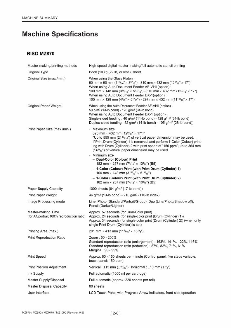
RISO MZ870
Master-making/printing methods High-speed digital master-making/full automatic stencil printing
Original Type Book (10 kg (22 lb) or less), sheet
Original Size (max./min.) When using the Glass Platen : 50 mm 90 mm (115/16" 39/16") - 310 mm 432 mm (123/16" 17")When using Auto Document Feeder AF-VI:II (option) : 100 mm 148 mm (315/16" 513/16") - 310 mm 432 mm (123/16" 17")When using Auto Document Feeder DX-1(option) : 105 mm 128 mm (41/8" 51/16") - 297 mm 432 mm (1111/16" 17")
Original Paper Weight When using the Auto Document Feeder AF-VI:II (option) : 50 g/m2 (13-lb bond) - 128 g/m2 (34-lb bond)When using Auto Document Feeder DX-1 (option) : Single-sided feeding : 40 g/m2 (11-lb bond) - 128 g/m2 (34-lb bond)Duplex-sided feeding : 52 g/m2 (14-lb bond) - 105 g/m2 (28-lb bond))
Print Paper Size (max./min.) • Maximum size320 mm 432 mm (129/16" 17")**Up to 555 mm (2113/16") of vertical paper dimension may be used.If Print Drum (Cylinder) 1 is removed, and perform 1-Color (Colour) print-ing with Drum (Cylinder) 2 with print speed of “150 ppm”, up to 364 mm (145/16") of vertical paper dimension may be used.
• Minimum size– Dual-Color (Colour) Print
182 mm 257 mm (73/16" 101/8") (B5)– 1-Color (Colour) Print (with Print Drum (Cylinder) 1)
100 mm 148 mm (315/16" 513/16")– 1-Color (Colour) Print (with Print Drum (Cylinder) 2)
182 mm 257 mm (73/16" 101/8") (B5)
Paper Supply Capacity 1000 sheets (64 g/m2 (17-lb bond))
Print Paper Weight 46 g/m2 (13-lb bond) - 210 g/m2 (110-lb index)
Image Processing mode Line, Photo (Standard/Portrait/Group), Duo (Line/Photo/Shadow off), Pencil (Darker/Lighter)
Master-making Time(for A4/portrait/100% reproduction ratio)
Approx. 57 seconds (for Dual-Color print)Approx. 24 seconds (for single-color print (Drum (Cylinder) 1))Approx. 34 seconds (for single-color print (Drum (Cylinder) 2)) (when only single Print Drum (Cylinder) is set)
Printing Area (max.) 291 mm 413 mm (117/16" 161/4")
Print Reproduction Ratio Zoom : 50 - 200%Standard reproduction ratio (enlargement) : 163%, 141%, 122%, 116%Standard reproduction ratio (reduction) : 87%, 82%, 71%, 61%Margin+ : 90 - 99%
Print Speed Approx. 60 - 150 sheets per minute (Control panel: five steps variable, touch panel: 150 ppm)
Print Position Adjustment Vertical : ±15 mm (±19/32") Horizontal : ±10 mm (±3/8")
Ink Supply Full automatic (1000 ml per cartridge)
Master Supply/Disposal Full automatic (approx. 220 sheets per roll)
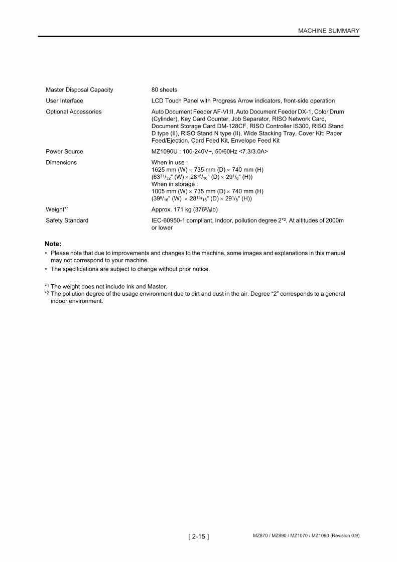
Master Disposal Capacity 80 sheets
User Interface LCD Touch Panel with Progress Arrow indicators, front-side operation

[ 2-9 ] MZ870 / MZ890 / MZ1070 / MZ1090 (Revision 0.9)
MACHINE SUMMARY
Note:• Please note that due to improvements and changes to the machine, some images and explanations in this manual
may not correspond to your machine. • The specifications are subject to change without prior notice.
*1 The weight does not include Ink and Master.*2 The pollution degree of the usage environment due to dirt and dust in the air. Degree “2” corresponds to a general
indoor environment.
Optional Accessories Auto Document Feeder AF-VI:II, Auto Document Feeder DX-1, Color Drum (Cylinder), Key Card Counter, Job Separator, RISO Network Card, Document Storage Card DM-128CF, RISO Controller IS300, RISO Stand D type (II), RISO Stand N type (II), Wide Stacking Tray, Cover Kit: Paper Feed/Ejection, Card Feed Kit, Envelope Feed Kit
Power Source MZ870A : 100-240V~, 50/60Hz <7.3/3.0A>
Dimensions When in use : 1625 mm (W) 735 mm (D) 740 mm (H) (6331/32" (W) 2815/16" (D) 291/8" (H))When in storage : 1005 mm (W) 735 mm (D) 740 mm (H) (399/16" (W) 2815/16" (D) 291/8" (H))
Weight*1 Approx. 171 kg (3765/8lb)
Safety Standard IEC-60950-1 compliant, Indoor, pollution degree 2*2, At altitudes of 2000m or lower

[ 2-10 ]MZ870 / MZ890 / MZ1070 / MZ1090 (Revision 0.9)
MACHINE SUMMARY
Machine Specifications
RISO MZ890
Master-making/printing methods High-speed digital master-making/full automatic stencil printing
Original Type Book (10 kg (22 lb) or less), sheet
Original Size (max./min.) When using the Glass Platen : 50 mm 90 mm (115/16" 39/16") - 310 mm 432 mm (123/16" 17")When using Auto Document Feeder AF-VI:II (option) : 100 mm 148 mm (315/16" 513/16") - 310 mm 432 mm (123/16" 17")When using Auto Document Feeder DX-1(option) : 105 mm 128 mm (41/8" 51/16") - 297 mm 432 mm (1111/16" 17")
Original Paper Weight When using the Auto Document Feeder AF-VI:II (option) : 50 g/m2 (13-lb bond) - 128 g/m2 (34-lb bond)When using Auto Document Feeder DX-1 (option) : Single-sided feeding : 40 g/m2 (11-lb bond) - 128 g/m2 (34-lb bond)Duplex-sided feeding : 52 g/m2 (14-lb bond) - 105 g/m2 (28-lb bond))
Print Paper Size (max./min.) • Maximum size320 mm 432 mm (129/16" 17")**Up to 555 mm (2113/16") of vertical paper dimension may be used.If Print Drum (Cylinder) 1 is removed, and perform 1-Color (Colour) print-ing with Drum (Cylinder) 2 with print speed of “150 ppm”, up to 364 mm (145/16") of vertical paper dimension may be used.
• Minimum size– Dual-Color (Colour) Print
182 mm 257 mm (73/16" 101/8") (B5)– 1-Color (Colour) Print (with Print Drum (Cylinder) 1)
100 mm 148 mm (315/16" 513/16")– 1-Color (Colour) Print (with Print Drum (Cylinder) 2)
182 mm 257 mm (73/16" 101/8") (B5)
Paper Supply Capacity 1000 sheets (64 g/m2 (17-lb bond))
Print Paper Weight 46 g/m2 (13-lb bond) - 210 g/m2 (110-lb index)
Image Processing mode Line, Photo (Standard/Portrait/Group), Duo (Line/Photo/Shadow off), Pencil (Darker/Lighter)
Master-making Time(for A4/portrait/100% reproduction ratio)
Approx. 57 seconds (for Dual-Color print)Approx. 24 seconds (for single-color print (Drum (Cylinder) 1))Approx. 34 seconds (for single-color print (Drum (Cylinder) 2)) (when only single Print Drum (Cylinder) is set)
Printing Area (max.) 291 mm 425 mm (117/16" 163/4")
Print Reproduction Ratio Zoom : 50 - 200%Standard reproduction ratio (enlargement) : 200%, 154%, 129%, 121%Standard reproduction ratio (reduction) : 78%, 65%, 61%, 50%Margin+ : 90 - 99%
Print Speed Approx. 60 - 150 sheets per minute (Control panel: five steps variable, touch panel: 150 ppm)
Print Position Adjustment Vertical : ±15 mm (±19/32") Horizontal : ±10 mm (±3/8")
Ink Supply Full automatic (1000 ml per cartridge)
Master Supply/Disposal Full automatic (approx. 215 sheets per roll)
Master Disposal Capacity 80 sheets
User Interface LCD Touch Panel with Progress Arrow indicators, front-side operation

[ 2-11 ] MZ870 / MZ890 / MZ1070 / MZ1090 (Revision 0.9)
MACHINE SUMMARY
Note:• Please note that due to improvements and changes to the machine, some images and explanations in this manual
may not correspond to your machine. • The specifications are subject to change without prior notice.
*1 The weight does not include Ink and Master.*2 The pollution degree of the usage environment due to dirt and dust in the air. Degree “2” corresponds to a general
indoor environment.
Optional Accessories Auto Document Feeder AF-VI:II, Auto Document Feeder DX-1, Color Drum (Cylinder), Key Card Counter, Job Separator, RISO Network Card, Document Storage Card DM-128CF, RISO Controller IS300, RISO Stand D type (II), RISO Stand N type (II), Wide Stacking Tray, Cover Kit: Paper Feed/Ejection, Card Feed Kit, Envelope Feed Kit
Power Source MZ890U : 100-240V~, 50/60Hz <7.3/3.0A>
Dimensions When in use : 1625 mm (W) 735 mm (D) 740 mm (H) (6331/32" (W) 2815/16" (D) 291/8" (H))When in storage : 1005 mm (W) 735 mm (D) 740 mm (H) (399/16" (W) 2815/16" (D) 291/8" (H))
Weight*1 Approx. 171 kg (3765/8lb)
Safety Standard IEC-60950-1 compliant, Indoor, pollution degree 2*2, At altitudes of 2000m or lower

[ 2-12 ]MZ870 / MZ890 / MZ1070 / MZ1090 (Revision 0.9)
MACHINE SUMMARY
Machine Specifications
RISO MZ1070
Master-making/printing methods High-speed digital master-making/full automatic stencil printing
Original Type Book (10 kg (22 lb) or less), sheet
Original Size (max./min.) When using the Glass Platen : 50 mm 90 mm (115/16" 39/16") - 310 mm 432 mm (123/16" 17")When using Auto Document Feeder AF-VI:II (option) : 100 mm 148 mm (315/16" 513/16") - 310 mm 432 mm (123/16" 17")When using Auto Document Feeder DX-1(option) : 105 mm 128 mm (41/8" 51/16") - 297 mm 432 mm (1111/16" 17")
Original Paper Weight When using the Auto Document Feeder AF-VI:II (option) : 50 g/m2 (13-lb bond) - 128 g/m2 (34-lb bond)When using Auto Document Feeder DX-1 (option) : Single-sided feeding : 40 g/m2 (11-lb bond) - 128 g/m2 (34-lb bond)Duplex-sided feeding : 52 g/m2 (14-lb bond) - 105 g/m2 (28-lb bond))
Print Paper Size (max./min.) • Maximum size320 mm 432 mm (129/16" 17")**Up to 555 mm (2113/16") of vertical paper dimension may be used.If Print Drum (Cylinder) 1 is removed, and perform 1-Color (Colour) print-ing with Drum (Cylinder) 2 with print speed of “150 ppm”, up to 364 mm (145/16") of vertical paper dimension may be used.
• Minimum size– Dual-Color (Colour) Print
182 mm 257 mm (73/16" 101/8") (B5)– 1-Color (Colour) Print (with Print Drum (Cylinder) 1)
100 mm 148 mm (315/16" 513/16")– 1-Color (Colour) Print (with Print Drum (Cylinder) 2)
182 mm 257 mm (73/16" 101/8") (B5)
Paper Supply Capacity 1000 sheets (64 g/m2 (17-lb bond))
Print Paper Weight 46 g/m2 (13-lb bond) - 210 g/m2 (110-lb index)
Image Processing mode Line, Photo (Standard/Portrait/Group), Duo (Line/Photo/Shadow off), Pencil (Darker/Lighter)
Master-making Time(for A4/portrait/100% reproduction ratio)
Approx. 57 seconds (for Dual-Color print)Approx. 24 seconds (for single-color print (Drum (Cylinder) 1))Approx. 34 seconds (for single-color print (Drum (Cylinder) 2)) (when only single Print Drum (Cylinder) is set)
Printing Area (max.) 291 mm 413 mm (117/16" 161/4")
Print Reproduction Ratio Zoom : 50 - 200%Standard reproduction ratio (enlargement) : 163%, 141%, 122%, 116%Standard reproduction ratio (reduction) : 87%, 82%, 71%, 61%Margin+ : 90 - 99%
Print Speed Approx. 60 - 150 sheets per minute (Control panel: five steps variable, touch panel: 150 ppm)
Print Position Adjustment Vertical : ±15 mm (±19/32") Horizontal : ±10 mm (±3/8")
Ink Supply Full automatic (1000 ml per cartridge)
Master Supply/Disposal Full automatic (approx. 220 sheets per roll)
Master Disposal Capacity 80 sheets
User Interface LCD Touch Panel with Progress Arrow indicators, front-side operation

[ 2-13 ] MZ870 / MZ890 / MZ1070 / MZ1090 (Revision 0.9)
MACHINE SUMMARY
Note:• Please note that due to improvements and changes to the machine, some images and explanations in this manual
may not correspond to your machine. • The specifications are subject to change without prior notice.
*1 The weight does not include Ink and Master.*2 The pollution degree of the usage environment due to dirt and dust in the air. Degree “2” corresponds to a general
indoor environment.
Optional Accessories Auto Document Feeder AF-VI:II, Auto Document Feeder DX-1, Color Drum (Cylinder), Key Card Counter, Job Separator, RISO Network Card, Document Storage Card DM-128CF, RISO Controller IS300, RISO Stand D type (II), RISO Stand N type (II), Wide Stacking Tray, Cover Kit: Paper Feed/Ejection, Card Feed Kit, Envelope Feed Kit
Power Source MZ1070E : 220-240V~, 50/60Hz <3.0A>MZ1070A : 100-240V~, 50/60Hz <7.3/3.0A>
Dimensions When in use : 1625 mm (W) 735 mm (D) 740 mm (H) (6331/32" (W) 2815/16" (D) 291/8" (H))When in storage : 1005 mm (W) 735 mm (D) 740 mm (H) (399/16" (W) 2815/16" (D) 291/8" (H))
Weight*1 Approx. 171 kg (3765/8lb)
Safety Standard IEC-60950-1 compliant, Indoor, pollution degree 2*2, At altitudes of 2000m or lower

[ 2-14 ]MZ870 / MZ890 / MZ1070 / MZ1090 (Revision 0.9)
MACHINE SUMMARY
Machine Specifications
SpecificationsRISO MZ1090
Master-making/printing methods High-speed digital master-making/full automatic stencil printing
Original Type Book (10 kg (22 lb) or less), sheet
Original Size (max./min.) When using the Glass Platen : 50 mm 90 mm (115/16" 39/16") - 310 mm 432 mm (123/16" 17")When using Auto Document Feeder AF-VI:II (option) : 100 mm 148 mm (315/16" 513/16") - 310 mm 432 mm (123/16" 17")When using Auto Document Feeder DX-1(option) : 105 mm 128 mm (41/8" 51/16") - 297 mm 432 mm (1111/16" 17")
Original Paper Weight When using the Auto Document Feeder AF-VI:II : 50 g/m2 (13-lb bond) - 128 g/m2 (34-lb bond)When using Auto Document Feeder DX-1 : Single-sided feeding : 40 g/m2 (11-lb bond) - 128 g/m2 (34-lb bond)Duplex-sided feeding : 52 g/m2 (14-lb bond) - 105 g/m2 (28-lb bond)
Print Paper Size (max./min.) • Maximum size320 mm 432 mm (129/16" 17")**Up to 555 mm (2113/16") of vertical paper dimension may be used.If Print Drum (Cylinder) 1 is removed, and perform 1-Color (Colour) print-ing with Drum (Cylinder) 2 with print speed of “150 ppm”, up to 364 mm (145/16") of vertical paper dimension may be used.
• Minimum size– Dual-Color (Colour) Print
182 mm 257 mm (73/16" 101/8") (B5)– 1-Color (Colour) Print (with Print Drum (Cylinder) 1)
100 mm 148 mm (315/16" 513/16")– 1-Color (Colour) Print (with Print Drum (Cylinder) 2)
182 mm 257 mm (73/16" 101/8") (B5)
Paper Supply Capacity 1000 sheets (64 g/m2 (17-lb bond))
Print Paper Weight 46 g/m2 (13-lb bond) - 210 g/m2 (110-lb index)
Image Processing mode Line, Photo (Standard/Portrait/Group), Duo (Line/Photo/Shadow off), Pencil (Darker/Lighter)
Master-making Time(for A4/portrait/100% reproduction ratio)
Approx. 57 seconds (for Dual-Color print)Approx. 24 seconds (for single-color print (Drum (Cylinder) 1))Approx. 34 seconds (for single-color print (Drum (Cylinder) 2)) (when only single Print Drum (Cylinder) is set)
Printing Area (max.) 291 mm 425 mm (117/16" 163/4")
Print Reproduction Ratio Zoom : 50 - 200%Standard reproduction ratio (enlargement) : 200%, 154%, 129%, 121%Standard reproduction ratio (reduction) : 78%, 65%, 61%, 50%Margin+ : 90 - 99%
Print Speed Approx. 60 - 150 sheets per minute (Control panel: five steps variable, touch panel: 150 ppm)
Print Position Adjustment Vertical : ±15 mm (±19/32") Horizontal : ±10 mm (±3/8")
Ink Supply Full automatic (1000 ml per cartridge)
Master Supply/Disposal Full automatic (approx. 215 sheets per roll)
[ 2-15 ] MZ870 / MZ890 / MZ1070 / MZ1090 (Revision 0.9)
MACHINE SUMMARY
Note:• Please note that due to improvements and changes to the machine, some images and explanations in this manual
may not correspond to your machine. • The specifications are subject to change without prior notice.
*1 The weight does not include Ink and Master.*2 The pollution degree of the usage environment due to dirt and dust in the air. Degree “2” corresponds to a general
indoor environment.
Master Disposal Capacity 80 sheets
User Interface LCD Touch Panel with Progress Arrow indicators, front-side operation
Optional Accessories Auto Document Feeder AF-VI:II, Auto Document Feeder DX-1, Color Drum (Cylinder), Key Card Counter, Job Separator, RISO Network Card, Document Storage Card DM-128CF, RISO Controller IS300, RISO Stand D type (II), RISO Stand N type (II), Wide Stacking Tray, Cover Kit: Paper Feed/Ejection, Card Feed Kit, Envelope Feed Kit
Power Source MZ1090U : 100-240V~, 50/60Hz <7.3/3.0A>
Dimensions When in use : 1625 mm (W) 735 mm (D) 740 mm (H) (6331/32" (W) 2815/16" (D) 291/8" (H))When in storage : 1005 mm (W) 735 mm (D) 740 mm (H) (399/16" (W) 2815/16" (D) 291/8" (H))
Weight*1 Approx. 171 kg (3765/8lb)
Safety Standard IEC-60950-1 compliant, Indoor, pollution degree 2*2, At altitudes of 2000m or lower

[ 2-16 ]MZ870 / MZ890 / MZ1070 / MZ1090 (Revision 0.9)
MACHINE SUMMARY
MEMO
MACHINE SUMMARY

[ 3-17 ] MZ870 / MZ890 / MZ1070 / MZ1090 (Revision 0.9)
MAIN DRIVE SECTION
CHAPTER 3: MAIN DRIVE SECTION
CONTENTS
Main Motor Belt Drive ..................................................................................3-2B-Position of No. 1 Print Drum Air Pump Gear Assembly ......................3-3Removing the Main Motor Assembly .........................................................3-4Removing the Main Belt ...............................................................................3-7

[ 3-18 ]MZ870 / MZ890 / MZ1070 / MZ1090 (Revision 0.9)
MAIN DRIVE SECTION
Main Motor Belt Drive
The Main motor drive is changed from Gear drive to Belt drive.
This is to reduce the noise during the printing.
Main motor Gear drive
on the existing MZ7 & MZ9 series.
Main motor Belt drive
on the new MZ8 & MZ10 series.
[ 3-19 ] MZ870 / MZ890 / MZ1070 / MZ1090 (Revision 0.9)
MAIN DRIVE SECTION
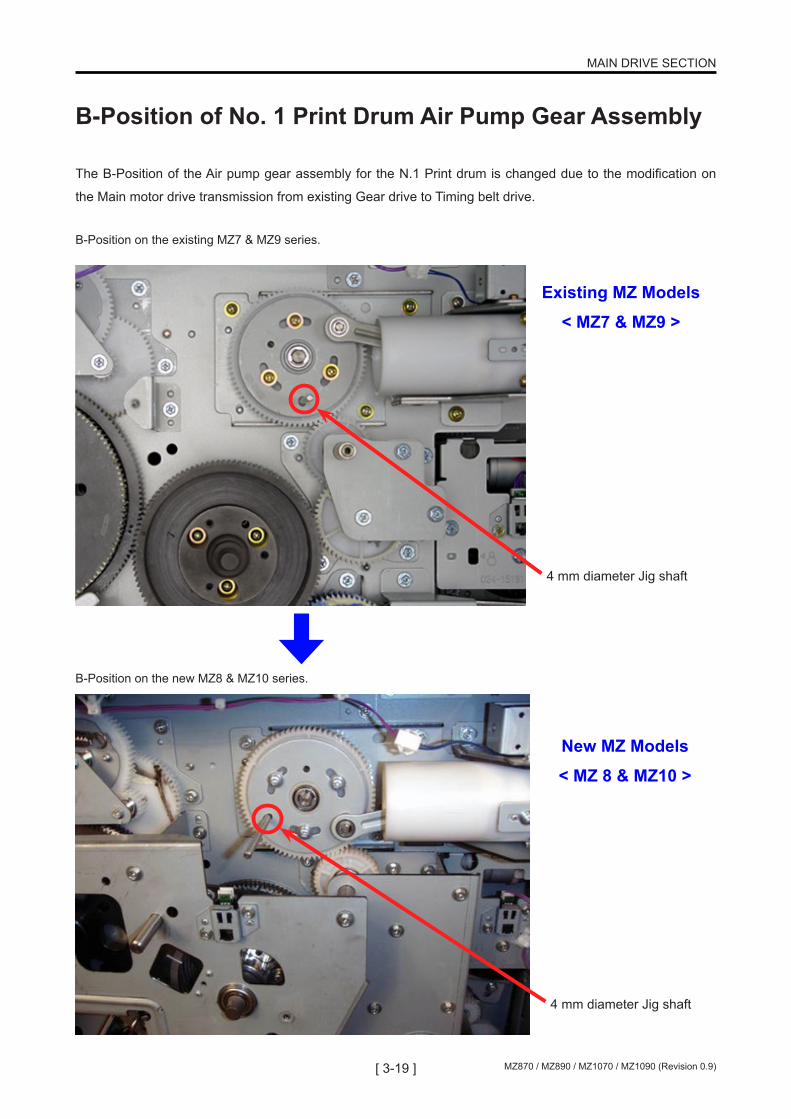
B-Position of No. 1 Print Drum Air Pump Gear Assembly
The B-Position of the Air pump gear assembly for the N.1 Print drum is changed due to the modification on
the Main motor drive transmission from existing Gear drive to Timing belt drive.
B-Position on the existing MZ7 & MZ9 series.
B-Position on the new MZ8 & MZ10 series.
4 mm diameter Jig shaft
4 mm diameter Jig shaft
Existing MZ Models
< MZ7 & MZ9 >
New MZ Models
< MZ 8 & MZ10 >

[ 3-20 ]MZ870 / MZ890 / MZ1070 / MZ1090 (Revision 0.9)
MAIN DRIVE SECTION
Removing the Main Motor Assembly
1. Turn OFF the machine power and disconnect the power cord from the machine.2. Remove the rear left and rear right covers and open the Mechanical control PCB.3. Remove the two Pressure springs, one for the No.1 Print drum and the other for the No.2 Print drum.4. Remove the mounting screws (4 pcs) from the Pressure control unit and push the unit away to the left to make working space.
5. Remove the Main belt tensioner plate assembly. (2 screws & 2 cap screws) Caution: Before loosening the screws and cap screws, make sure to memo down the belt tension scale setting. The tension should be made a little tighter after the assembly.
Pressure spring of Print drum No.1 Remove also that for Print drum No. 2
Pressure control unit
Main belt tensioner plate

[ 3-21 ] MZ870 / MZ890 / MZ1070 / MZ1090 (Revision 0.9)
MAIN DRIVE SECTION
Belt load reinforce plate
6. Remove the Main motor shaft bracket. (4 screws)7. Remove the Belt load reinforce plate. (4 screws)
Main motor shaft bracket
View after the two parts shown on the left are removed.
Tensioner base plate
8. Remove the Tensioner base plate. (4 screws)
[ 3-22 ]MZ870 / MZ890 / MZ1070 / MZ1090 (Revision 0.9)
MAIN DRIVE SECTION
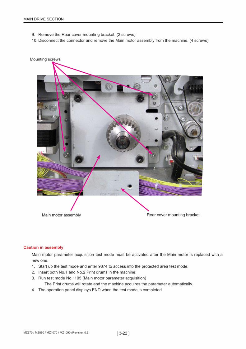
9. Remove the Rear cover mounting bracket. (2 screws)10. Disconnect the connector and remove the Main motor assembly from the machine. (4 screws)
Mounting screws
Main motor assembly Rear cover mounting bracket
Caution in assembly
Main motor parameter acquisition test mode must be activated after the Main motor is replaced with a new one.1. Start up the test mode and enter 9874 to access into the protected area test mode.2. Insert both No.1 and No.2 Print drums in the machine.3. Run test mode No.1105 (Main motor parameter acquisition) The Print drums will rotate and the machine acquires the parameter automatically.4. The operation panel displays END when the test mode is completed.

[ 3-23 ] MZ870 / MZ890 / MZ1070 / MZ1090 (Revision 0.9)
MAIN DRIVE SECTION
Removing the Main Belt
1. Turn OFF the machine power and disconnect the power cord from the machine.2. Remove the rear left and rear right covers and open the Mechanical control PCB.3. Remove the two Pressure springs, one for the No.1 Print drum and the other for the No.2 Print drum.4. Remove the mounting screws (4 pcs) from the Pressure control unit and push the unit away to the left to make working space.5. Remove the Main belt tensioner plate assembly. (2 screws & 2 cap screws) Caution: Before loosening the screws and cap screws, make sure to memo down the belt tension scale setting. The tension should be made a little tighter after the assembly.6. Remove the Main motor shaft bracket. (4 screws)7. Remove the Belt load reinforce plate. (4 screws)8. Remove the Tensioner base plate. (4 screws)9. Remove the Main cover. (7 screws)10. Remove the Pressure cam assembly for the No.1 Print drum. (3 screws)11. Remove the Main belt.
< Following steps No.1 through No.8 are the steps taken in removing the Main motor assembly.>
Pressure cam assembly
Main belt

[ 3-24 ]MZ870 / MZ890 / MZ1070 / MZ1090 (Revision 0.9)
MAIN DRIVE SECTION
MEMO
MAIN DRIVE SECTION

[ 4-1 ] MZ870 / MZ890 / MZ1070 / MZ1090 (Revision 0.9)
FIRST PAPER FEED SECTION
CHAPTER 4: FIRST PAPER FEED SECTION
CONTENTS
Initial Paper Feed Operation ........................................................................4-2

[ 4-2 ]MZ870 / MZ890 / MZ1070 / MZ1090 (Revision 0.9)
FIRST PAPER FEED SECTION
Initial Paper Feed Operation
At the start of a print job, the main motor switches ON and rotates the print drum via Timing belt and drives the Print drum pulley.The paper feed clutch gear rotates continuously when the main motor is ON.When the print drum rotates from position-B to a certain angle (angle set by adjusting the paper feed clutch ON angle during test mode or by the custom paper feed ON timing), the paper feed clutch switches ON, turning the scraper and pickup roller and transporting paper from the paper feed tray into the machine.When the print drum rotates through a certain angle (angle set by adjusting the paper feed clutch OFF angle in test mode or by the amount of slack set during custom paper feed adjustment) after the paper is fed into the machine and the paper sensor senses light, the paper feed clutch switches OFF, and the first paper feed operation stops.In this process, the leading edge of the paper contacts the guide roller and timing roller. When paper transport stops, some slack is left in the paper.Additionally, when the print drum rotates to the paper feed jam detection angle/IN angle after the paper feed clutch switches ON, the machine polls the paper sensor for a paper failure feed error.The scraper and pickup roller are equipped with a one-way clutch to enable free rotation and to keep the first paper feed section from halting or slowing paper feeding after the paper is fed to the second paper feed section.
Main motor
Drum pulley
Paper feed clutch
Pickup rollerScraper
Scraper
Pickup roller
Paper sensor (receive)
Paper sensor (light emitter)
Stripper pad
Guide roller
Timing roller

[ 5-3 ] MZ870 / MZ890 / MZ1070 / MZ1090 (Revision 0.9)
SECOND PAPER FEED SECTION
CHAPTER 5: SECOND PAPER FEED SECTION
CONTENTS
Removing the Timing Roller ........................................................................5-2

[ 5-4 ]MZ870 / MZ890 / MZ1070 / MZ1090 (Revision 0.9)
SECOND PAPER FEED SECTION
Removing the Timing Roller
1. Remove Print drum No.1, turn oFF the machine power and disconnect the Power cable from the machine.2. Remove the rear left and rear right covers and open the Mechanical control PCB.3. Remove the Paper sensor (send).4. Insert 8 mm Jig shaft through the Main cover, Pressure cam and machine frame on the Print drum No.1 side.
IMPORTANT ! This is to prevent injury from the sudden movements of the gears when working on the drive area, especially when the Pressure springs are hooked on the Pressure lever assembly.
8 mm Jig shaft
B-position 8 mm Jig shaft inserting hole
[ 5-5 ] MZ870 / MZ890 / MZ1070 / MZ1090 (Revision 0.9)
SECOND PAPER FEED SECTION
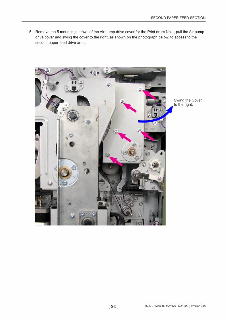
5. Remove the 5 mounting screws of the Air pump drive cover for the Print drum No.1, pull the Air pump drive cover and swing the cover to the right, as shown on the photograph below, to access to the second paper feed drive area.
Swing the Cover to the right.

[ 5-6 ]MZ870 / MZ890 / MZ1070 / MZ1090 (Revision 0.9)
SECOND PAPER FEED SECTION
6. Remove the second idler spring, loosen the two mounting screws, slide the second idler assembly, then loosen the tension of the second paper feed drive belt and remove the second paper feed drive belt.7. Remove the E-ring and bearing on the front side.
Second idler spring
Second idler assembly
S e c o n d p a p e r feed drive belt
Guide roller pressure spring
E-ring Bearing

[ 5-7 ] MZ870 / MZ890 / MZ1070 / MZ1090 (Revision 0.9)
SECOND PAPER FEED SECTION
8. Remove the T-roller bracket mounting screws (3 screws) and pull the timing roller towards the front through the larger end of the keyhole-shaped opening in the machine frame.
< Timing Roller >
Timing roller
Key-shaped opening
T-roller bracket

[ 5-8 ]MZ870 / MZ890 / MZ1070 / MZ1090 (Revision 0.9)
SECOND PAPER FEED SECTION
MEMO

[ 11-9 ] MZ870 / MZ890 / MZ1070 / MZ1090 (Revision 0.9)
MASTER REMOVAL SECTION
CHAPTER 11: MASTER REMOVAL SECTION
CONTENTS
Master Disposal Box ..................................................................................11-2

[ 11-10 ]MZ870 / MZ890 / MZ1070 / MZ1090 (Revision 0.9)
MASTER REMOVAL SECTION
Master Disposal Box
The Master disposal unit is changed to that of EZ type.Small parts on the Master disposal box is different from the EZ unit, so as a unit, the Master disposal box on MZ8 & MZ10 Series differs from that of EZ machine.
With the change on the Master disposal box, the Master disposal box is changed to that of EZ type.The No.1 Print drum master disposal box is identical to the EZ.The No.2 Print drum master disposal box is also EZ type, but is new, as the master throw away direction is opposite from the No.1 print drum master disposal box.
Existing MZ7 & MZ9 Series Master disposal box.
New MZ8 & MZ10No.1 Drum master disposal box
New MZ8 & MZ10No.2 Drum master disposal box

[ 14-1 ] MZ870 / MZ890 / MZ1070 / MZ1090 (Revision 0.9)
MASTER MAKING SECTION
CHAPTER 14: MASTER MAKING SECTION
CONTENTS
Removing the Master Making Upper Cover Safety Switch .....................14-2Removing the Master Positioning Sensor ...............................................14-3

[ 14-2 ]MZ870 / MZ890 / MZ1070 / MZ1090 (Revision 0.9)
MASTER MAKING SECTION
Master making unit upper cover set sensor, located on the Cutter cover assembly is changed from an interrupt sensor to a Micro switch, as it is on the EZ machines.
Removal Procedure
1. Pull out the Master making unit from the machine, turn OFF the machine power and disconnect the power cord from the machine.2. Open the Master making upper unit and remove the Cutter cover assembly.3. Disconnect the connector and remove the Master making upper cover safety switch together with the switch bracket. (1 screw)
Removing the Master Making Upper Cover Safety Switch
Maser making unit upper cover safety switch
Cutter Cover Assembly (Top View)

[ 14-3 ] MZ870 / MZ890 / MZ1070 / MZ1090 (Revision 0.9)
MASTER MAKING SECTION
1. Pull out the Master making unit from the machine, turn OFF the machine power and disconnect the power cord from the machine.2. Open the Master making upper unit and remove the Cutter cover assembly.3. Remove the Master positioning sensor cover. (1 screw)4. Disconnect the connector, and remove the Master positioning sensor.
Removing the Master Positioning Sensor
Master positioning sensor cover
Master positioning sensor
Master positioning sensor cover
Master positioning sensor bracketThe mounting screw on this bracket must not be loosened.The mounting position is set by a JIG at the factory.
DO NOT LOOSEN THIS SCREW !Master positioning sensor bracketThe mounting screw on this bracket must not be loosened.The mounting position is set by a JIG at the factory.

[ 14-4 ]MZ870 / MZ890 / MZ1070 / MZ1090 (Revision 0.9)
MASTER MAKING SECTION
MEMO

[ 15-5 ] MZ870 / MZ890 / MZ1070 / MZ1090 (Revision 0.9)
TEST MODE
CHAPTER 15: TEST MODE
CONTENTS
1. Operating Method ......................................................................................15-31) Launching Test Mode .........................................................................15-32) Operation ............................................................................................15-33) Ending Test Mode ...............................................................................15-3
2. Testing Methods ........................................................................................15-41) Sensor/switch check ...........................................................................15-42) Motor/solenoid check ..........................................................................15-43) Unit operation check ...........................................................................15-44) Data clear ............................................................................................15-45) Data check ..........................................................................................15-46) Data set ...............................................................................................15-4
3. System Panel Test Mode ...........................................................................15-54. Imaging/Scanning Test Mode .................................................................15-145. Master-making/Master-disposal Test Mode ..........................................15-186. Paper-feed/Paper-eject Test Mode .........................................................15-237. Print Drum/ Print Adjustment Test Mode ..............................................15-298. Protected Area Test Mode ......................................................................15-389. Test Mode for Optional Unit (AF) ...........................................................15-4210. Test Mode for Optional Unit (Job Separator) .......................................15-4511. Test Mode for Optional Unit (Storage Memory) ...................................15-4612. Test Mode for Optional Unit (Linked Printer) .......................................15-47

[ 15-6 ]MZ870 / MZ890 / MZ1070 / MZ1090 (Revision 0.9)
TEST MODE
MEMO

[ 15-7 ] MZ870 / MZ890 / MZ1070 / MZ1090 (Revision 0.9)
TEST MODE
1. Operating Method
1) Launching Test Mode
To start Test Mode, switch on power while simultaneously pressing the < > and < > keys for first print drum position adjustment on the operation panel. This sets the machine in Test Mode standby status.
2) Operation
A Test Mode No. can be entered (selected) via keys or by selecting from the menu.
a) Using keys
(1) When the machine is in standby status, enter a desired Test Mode No. using the ten-key pad. To cor-rect input, press the < C > key and press the desired key.
(2) Press the Start key to start Test Mode operations.
(3) Press the Stop or Start key to exit Test Mode operations and to set the machine in non-operating or standby status.
* When parameters are being set, pressing the Start key after changing data registers the input data and sets the machine in standby status. Pressing the Stop key cancels the setting and places the machine in standby.
b) Selecting from the menu
(1) When the machine is in the standby status, select a unit from the Test Mode menu that includes the test item to be executed.
* Press with a finger on the name of a desired unit on the LCD screen. (This highlights the selected unit name.)
* The screen displays the Test Mode sub-menu.
(2) Select the test item to be executed from the Test Mode sub-menu.
* Press with a finger on Test Mode operations on the LCD screen. (This highlights the selected test name.)
(3) Press the Start key to start the Test Mode operations.
(4) Press the Stop or Start key to exit Test Mode and set the machine in non-operating or standby status.
* When parameters are being set, pressing the Start key after changing data registers the data and sets the machine in standby status. Pressing the Stop key cancels the setting and places the machine in standby.
3) Ending Test Mode
When the machine is in Test Mode standby status or in Test Mode non-operating status, depress the Reset key for 1 or more seconds to exit Test Mode.

[ 15-8 ]MZ870 / MZ890 / MZ1070 / MZ1090 (Revision 0.9)
TEST MODE
2. Testing Methods
1) Sensor/switch check
The statuses of the sensors and switches are indicated by a buzzer.
• Detecting condition: The buzzer beeps at intervals of 0.1 seconds (quick successive beeps)
• Non-detecting condition: The buzzer beeps at intervals of 0.5 seconds (slightly-prolonged successive beeps)
2) Motor/solenoid check
Pressing the Start key switches the motor/solenoid ON. Pressing the Start or Stop keys halts the motor/solenoid.
* Note that since error checks are not performed during operations, the moving section may become locked at a limit position if one is set.
3) Unit operation check
(1) Press the Start key to operate the unit. In general, ordinary error checks will be performed. Some units will stop after completing a series of operations, while others continue operating until a key (Stop key or Start key) is pressed.
(2) An error will result in a continuous buzzer sound. Press the Reset key to clear the error.
4) Data clear
Press the Start key to start the operation. The screen will display <In Action>. After a brief period during which this indication is displayed, the operation halts automatically, and the screen displays <End>.
5) Data check
Press the Start key to display settings and parameters.
* Set values are displayed but cannot be changed during data check operation.
6) Data set
(1) Pressing the Start key to change the currently displayed settings and parameters.
(2) Change the data using the ten-key pad. Use the < * > key to switch between +/- indications.
(3) After changing a set value, press the Start key to register the data. The machine will enter standby sta-tus. Pressing the Stop key cancels the setting and places the machine in standby.
* Entering a value outside the permissible range will return the setting to the default value. Entering a value incompatible with the setting unit will return the setting to the default value.
[ 15-9 ] MZ870 / MZ890 / MZ1070 / MZ1090 (Revision 0.9)
TEST MODE
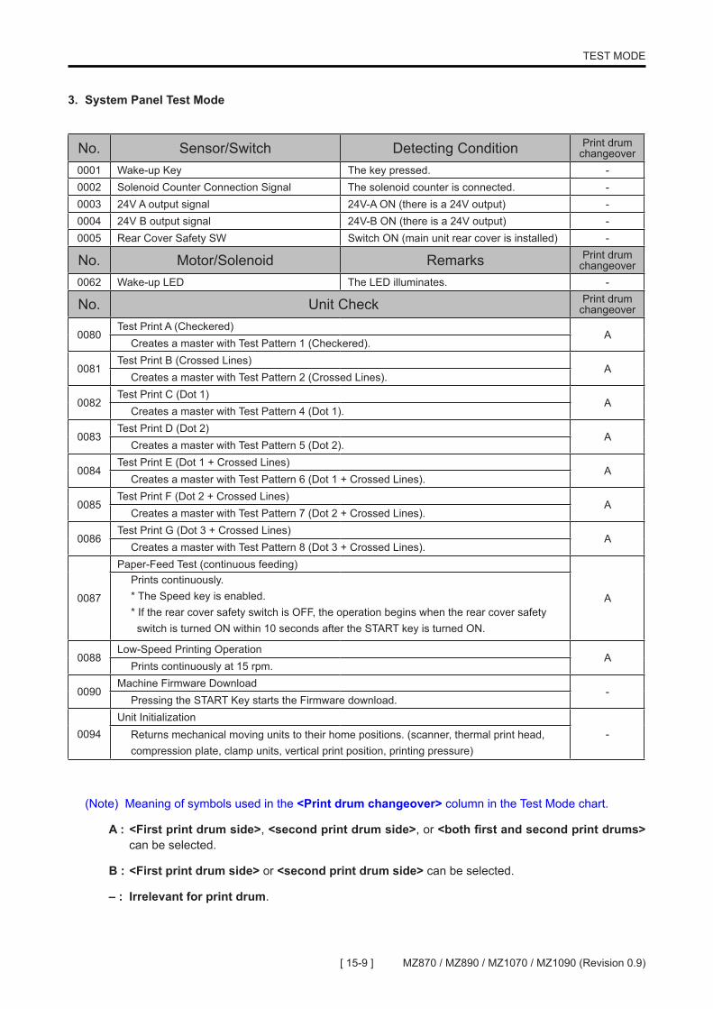
3. System Panel Test Mode
No. Sensor/Switch Detecting Condition Print drum changeover
0001 Wake-up Key The key pressed. -0002 Solenoid Counter Connection Signal The solenoid counter is connected. -0003 24V A output signal 24V-A ON (there is a 24V output) -0004 24V B output signal 24V-B ON (there is a 24V output) -0005 Rear Cover Safety SW Switch ON (main unit rear cover is installed) -
No. Motor/Solenoid Remarks Print drum changeover
0062 Wake-up LED The LED illuminates. -
No. Unit Check Print drum changeover
0080Test Print A (Checkered)
ACreates a master with Test Pattern 1 (Checkered).
0081Test Print B (Crossed Lines)
ACreates a master with Test Pattern 2 (Crossed Lines).
0082Test Print C (Dot 1)
ACreates a master with Test Pattern 4 (Dot 1).
0083Test Print D (Dot 2)
ACreates a master with Test Pattern 5 (Dot 2).
0084Test Print E (Dot 1 + Crossed Lines)
ACreates a master with Test Pattern 6 (Dot 1 + Crossed Lines).
0085Test Print F (Dot 2 + Crossed Lines)
ACreates a master with Test Pattern 7 (Dot 2 + Crossed Lines).
0086Test Print G (Dot 3 + Crossed Lines)
ACreates a master with Test Pattern 8 (Dot 3 + Crossed Lines).
0087
Paper-Feed Test (continuous feeding)
A
Prints continuously.* The Speed key is enabled. * If the rear cover safety switch is OFF, the operation begins when the rear cover safety switch is turned ON within 10 seconds after the START key is turned ON.
0088Low-Speed Printing Operation
APrints continuously at 15 rpm.
0090Machine Firmware Download
-Pressing the START Key starts the Firmware download.
0094Unit Initialization
-Returns mechanical moving units to their home positions. (scanner, thermal print head, compression plate, clamp units, vertical print position, printing pressure)
(Note) Meaning of symbols used in the <Print drum changeover> column in the Test Mode chart.
A : <First print drum side>, <second print drum side>, or <both first and second print drums> can be selected.
B : <First print drum side> or <second print drum side> can be selected.
– : Irrelevant for print drum.

[ 15-10 ]MZ870 / MZ890 / MZ1070 / MZ1090 (Revision 0.9)
TEST MODE
No. Unit Check Print drum changeover
0095System Configuration Data Output
BCreates a master for CI system data.
0097System Parameter & Error Record Print
BCreates a master of the list of data setting changes and error history. * The master is created by the first print drum.
0101
Machine Clock Activation
-Writes the time information set in Test No. 0171 to No. 0173 to the RTC and starts the time count. Pressing the Start key begins the operation and automatically stops it after 0.5 seconds.
0102DSP Download (Main, Secondary)
-Pressing the Start key begins download of the DSP program for controlling the main motor and second paper feed.
0103
Machine Test-Mode Data Recording
-Stores the maine Test Mode setting in NeoROSA PCB into CF card.<Excludes the test modes for Duplex Scanner Unit TM2760-TM2999.>
0104Print Drum Test-Mode Data Recording
BStores the print-drum Test Mode Settings now in the EEPROM of the Print Drum into CF card. <This test mode is not displayed on the Operation Panel.>
0105Machine Test-Mode Data Re-store
-Writes the test mode settings retrieved in CF card by test-mode No.0103 into the SH PCB.
0106Print Drum Test-Mode Data Re-store
BWrites the test mode settings retrieved in CF card by test-mode No.0104 into the Print Drum PCB EEPROM. <This test mode is not displayed on the Operation Panel.>
0107
Test Mode Data Back-up
-Stores all the test mode numbers and settings, which are changed from the program default, are stored in CF card for record keeping purpose. <This test mode is not displayed on the Operation Panel.>
No. Data Clear Details Print drum changeover
0110 Clearing Jam Status Data
Normally, when a paper jam occurs, the error can be cleared only by following the jam reset procedure and removing the cause of the jam. However, this setting will force an error caused by jamming to be cleared. Note that errors involving consumables cannot be cleared.
-
0111 Clearing User Memory
Clears data (memory function, programs, properties settings, etc.) in the user area (data returned to default values). * Be sure to record all data before executing this function. * Data relating to Authentication settings cannot be cleared <TM118 needs to be used.>
-
0112Clearing Normal Area Test-Mode DataMemory (Machine)
Returns all settings stored in the main unit FRAM and main unit EEPROM in the Test Mode to their default values.<This test mode is not displayed on the Operation Panel.> * Does not clear data in protected areas. * Be sure to record all data before executing this function.
-
[ 15-11 ] MZ870 / MZ890 / MZ1070 / MZ1090 (Revision 0.9)
TEST MODE
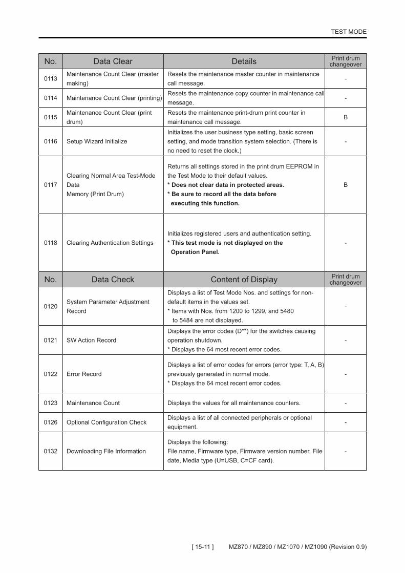
No. Data Clear Details Print drum changeover
0113Maintenance Count Clear (master making)
Resets the maintenance master counter in maintenance call message.
-
0114 Maintenance Count Clear (printing)Resets the maintenance copy counter in maintenance call message.
-
0115Maintenance Count Clear (print drum)
Resets the maintenance print-drum print counter in maintenance call message.
B
0116 Setup Wizard InitializeInitializes the user business type setting, basic screen setting, and mode transition system selection. (There is no need to reset the clock.)
-
0117Clearing Normal Area Test-Mode DataMemory (Print Drum)
Returns all settings stored in the print drum EEPROM in the Test Mode to their default values. * Does not clear data in protected areas. * Be sure to record all the data before executing this function.
B
0118 Clearing Authentication SettingsInitializes registered users and authentication setting.* This test mode is not displayed on the Operation Panel.
-
No. Data Check Content of Display Print drum changeover
0120System Parameter Adjustment Record
Displays a list of Test Mode Nos. and settings for non-default items in the values set. * Items with Nos. from 1200 to 1299, and 5480 to 5484 are not displayed.
-
0121 SW Action RecordDisplays the error codes (D**) for the switches causing operation shutdown. * Displays the 64 most recent error codes.
-
0122 Error RecordDisplays a list of error codes for errors (error type: T, A, B) previously generated in normal mode. * Displays the 64 most recent error codes.
-
0123 Maintenance Count Displays the values for all maintenance counters. -
0126 Optional Configuration CheckDisplays a list of all connected peripherals or optional equipment.
-
0132 Downloading File InformationDisplays the following:File name, Firmware type, Firmware version number, File date, Media type (U=USB, C=CF card).
-

[ 15-12 ]MZ870 / MZ890 / MZ1070 / MZ1090 (Revision 0.9)
TEST MODE
No. Data Check Content of Display Print drum changeover
0135Paper size on feed tray is displayed by ID numbers.
Identifies and displays a paper ID determined based on information from the paper width potentiometer and paper size detection sensor. * Paper IDs and paper sizes
-
00: No paper 01: A3 03: A4 05: B5 07: A5 09: B6 11: Postcard 13: Ledger 15: Letter
02: B4 04: A4 landscape 06: B5 landscape 08: A5 landscape 10: B6 landscape 12: Postcard landscape 14: Legal 16: Letter landscape
17: Statement 18: Statement landscape 19: Foolscap30: Chinese paper K1631: Chinese paper K16 Landscape32: Chinese paper K8 50: Paper size undefined 1 (paper size detection sensor: ON) 51: Paper size undefined 2 (paper size detection sensor: OFF)
No. Data Setting Print drum changeover
0141Counter Display Control
-Description Selection to display or not display the counter.Setting Setting range: 0: (Not displayed) 1: (Displayed) - default.
0142
Test Mode Language
-Description Selects the language for the Test Mode display.
SettingSetting range: 0: (Normal) 1: (Japanese) 2: (English) 3: (Chinese). Default: 0: (Normal)
0143
Maintenance-Master Count Entry
-Description
Sets the number of masters at which the maintenance call message is displayed.
SettingSetting range: 0 to 9999 (x 100) masters Setting unit: 1 (x 100) masters Default: 0 master <does not display maintenance call message>.
0144
Maintenance-Copy Count Entry
-Description Sets the number of prints at which the maintenance call message is displayed.
SettingSetting range: 0 to 9999 (x 1000) sheets Setting unit: 1 (x 1000) sheets Default: 0 sheet <does not display maintenance call message>.
0145
Maintenance-Drum Meter Entry
BDescription
Sets the number of print-drum pressurizing times at which the maintenance call message is displayed (data stored in print drum PCB).
SettingSetting range: 0 to 9999 (x 1000) sheets Setting unit: 1 (x 1000) sheets Default: 0 sheet <does not display maintenance call message>.

[ 15-13 ] MZ870 / MZ890 / MZ1070 / MZ1090 (Revision 0.9)
TEST MODE
No. Data Setting Print drum changeover
0146
Scan First
-Description
Selects whether scanning is done before master-removal, or do the scanning and master-removal at the same time.
SettingSetting range: 0 (Inactive - both done at the same time) - default 1 (Active - scanning is done before master-making)
0149
Authentication Enable/Disable Selection
-Description
Selects whether to enable or disable the authentication function.<This test mode is not displayed on the Operation Panel.>
SettingSetting range: 0 (Disable) 1 (Enable) - default.
0150
Print Quantity Reset Setting
-Description
Sets whether the print count value is reset or not when continuous print is set to OFF.
SettingSetting range: 0 (Reset disabled), 1 (Reset enabled) Default: 0 (Reset disabled)
0151
Print Speed After Short Interval
-Description Enables/disables the gradual print speed acceleration operation.
SettingSetting range: 0 (Disabled), 1 (Enabled) Default: 0 (Disabled)
0152
Lighten Print Display Selection [Only on MZ9/MV9 Series]
-Description Enables/disables the Lighten Print display in the Function tab.
SettingSetting range: 0 (Hide), 1 (Display) Default: 0 (Hide)
0153
Special Paper Control Basic Display Selection
-Description Selects whether to display the Special Paper Control button in the Admin. Tab.
SettingSetting range: 0 (Hide), 1 (Display) Default: 0 (Hide)
0154
Minimum Print Quantity Control
-Description Enables/disables the Minimum Print Quantity setting in the Admin. tab.
SettingSetting range: 0 (Setting change disabled), 1 (Setting change enabled) Default: 0 (Setting change enabled)
[ 15-14 ]MZ870 / MZ890 / MZ1070 / MZ1090 (Revision 0.9)
TEST MODE
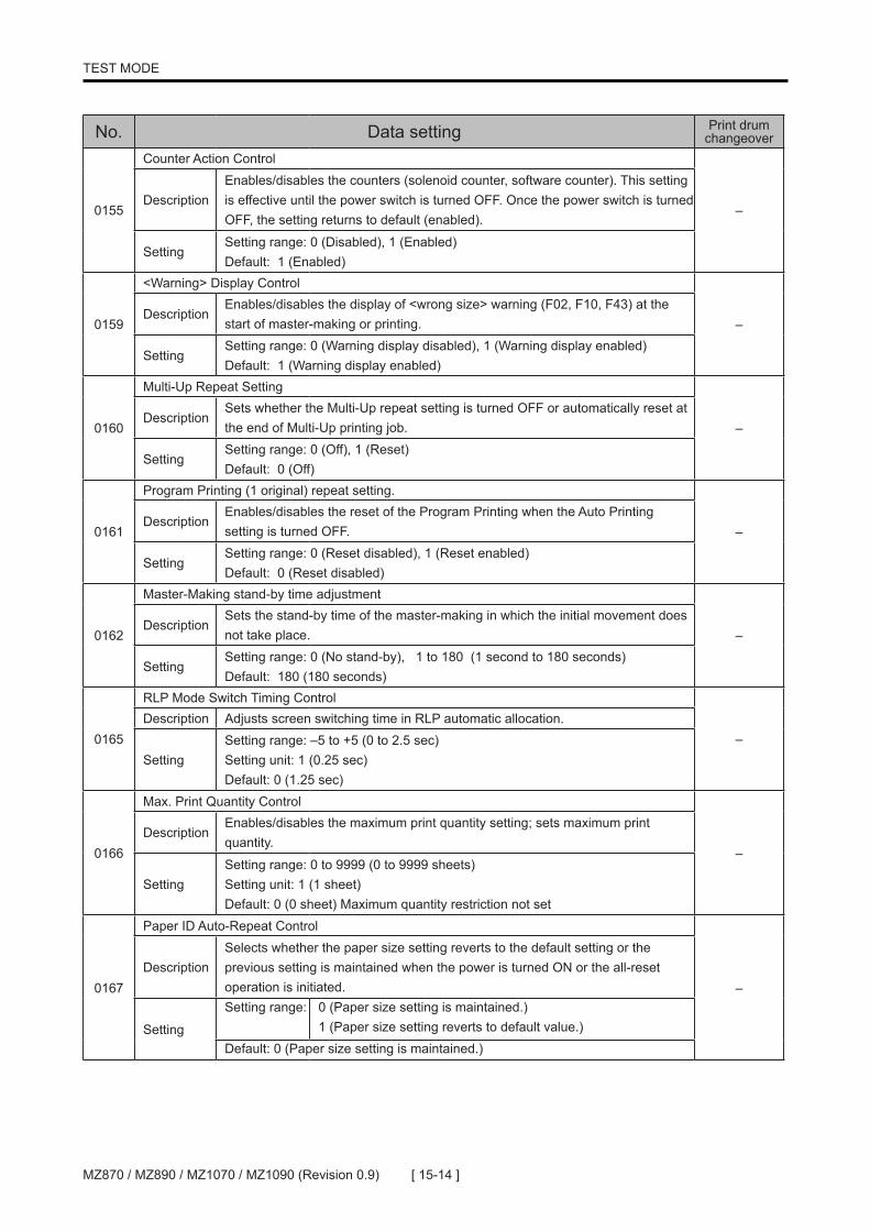
No. Data setting Print drum changeover
0155
Counter Action Control
–Description
Enables/disables the counters (solenoid counter, software counter). This setting is effective until the power switch is turned OFF. Once the power switch is turned OFF, the setting returns to default (enabled).
SettingSetting range: 0 (Disabled), 1 (Enabled) Default: 1 (Enabled)
0159
<Warning> Display Control
–Description
Enables/disables the display of <wrong size> warning (F02, F10, F43) at the start of master-making or printing.
SettingSetting range: 0 (Warning display disabled), 1 (Warning display enabled) Default: 1 (Warning display enabled)
0160
Multi-Up Repeat Setting
–Description
Sets whether the Multi-Up repeat setting is turned OFF or automatically reset at the end of Multi-Up printing job.
SettingSetting range: 0 (Off), 1 (Reset) Default: 0 (Off)
0161
Program Printing (1 original) repeat setting.
–Description
Enables/disables the reset of the Program Printing when the Auto Printing setting is turned OFF.
SettingSetting range: 0 (Reset disabled), 1 (Reset enabled) Default: 0 (Reset disabled)
0162
Master-Making stand-by time adjustment
–Description
Sets the stand-by time of the master-making in which the initial movement does not take place.
SettingSetting range: 0 (No stand-by), 1 to 180 (1 second to 180 seconds) Default: 180 (180 seconds)
0165
RLP Mode Switch Timing Control
–Description Adjusts screen switching time in RLP automatic allocation.
SettingSetting range: –5 to +5 (0 to 2.5 sec) Setting unit: 1 (0.25 sec) Default: 0 (1.25 sec)
0166
Max. Print Quantity Control
–Description
Enables/disables the maximum print quantity setting; sets maximum print quantity.
SettingSetting range: 0 to 9999 (0 to 9999 sheets) Setting unit: 1 (1 sheet) Default: 0 (0 sheet) Maximum quantity restriction not set
0167
Paper ID Auto-Repeat Control
–Description
Selects whether the paper size setting reverts to the default setting or the previous setting is maintained when the power is turned ON or the all-reset operation is initiated.
Setting
Setting range: 0 (Paper size setting is maintained.) 1 (Paper size setting reverts to default value.)
Default: 0 (Paper size setting is maintained.)

[ 15-15 ] MZ870 / MZ890 / MZ1070 / MZ1090 (Revision 0.9)
TEST MODE
No. Data setting Print drum changeover
0168
Fine Adjustment Button Display Control
–Description Used to display or hide the fine adjustment button.
Setting
Setting range: 0 (Hidden) 1 (Display)
Default: 0 (Hidden)
0169
<Properties> Tab Display Control
–Description Display or hide the properties setting tab.
Setting
Setting range: 0 (Hidden) 1 (Display)
Default: 1 (Display)
0170
Stock Management
–Description Display or hide the Stock Management display in Admin. Tab.
Setting
Setting range: 0 (Hide) 1 (Display)
Default: 0 (Hide)
0171
Machine Clock Setting (YEAR)
–
Sets the <year> in the <year/month/date> setting in the RTC. * Test Mode No. 0101 must be activated after values are entered in Test Mode No. 0171 through No. 0173. Executing Test No. 0101 registers the values set in
Setting
Setting range: 2000 to 2199 (Year 2000 to 2199) Setting unit: 1 (1 year) Default: 2000 before RTC is set (before Test No. 0101 is executed).
RTC measured value at the time of test activation after RTC is set (after Test No. 0101 is executed).
0172
Machine Clock Setting (MONTH & DATE)
–
Sets the <month/date> in the <year/month/date> setting in the RTC. * Test Mode No. 0101 must be activated after values are entered in Test Mode No. 0171 through No. 0173. Executing Test No. 0101 registers the values set in
Setting
0101 before RTC is set (before Test No. 0101 is executed) RTC measured value at the time of test activation after RTC is set (after Test No. 0101 is executed)
Default: 0101 before RTC is set (before Test No. 0101 is executed) RTC measured value at the time of test activation after RTC is set (after Test No. 0101 is executed)
0173
Machine Clock Setting (HOUR & MINUTE)
–
Sets <hour/minute> in the RTC. * Test Mode No. 0101 must be activated after values are entered in Test Mode No. 0171 through No. 0173. Executing Test No. 0101 registers the values set in Test Mode No. 0171 through No. 0173 into the RTC.
Setting
Setting range: Two upper digits: 00 to 23 (0 to 23 o’clock), two lower digits: 00 to 59 (00 to 59 minutes) Setting unit: 1
Default: 0000 before RTC is set (before Test No. 0101 is executed) RTC measured value at the time of test activation after RTC is set (after Test No. 0101 is executed)

[ 15-16 ]MZ870 / MZ890 / MZ1070 / MZ1090 (Revision 0.9)
TEST MODE
No. Data setting Print drum changeover
0174
Chinese Paper No.16 (Width data setting)
–Description Sets paper width data.
Setting
Setting range: 191 to 199 (191mm to 199mm) Setting unit: 1 = 1mmDefault: 195 (195mm)
0175
Chinese Paper No.8 (Width data setting)
–Description Sets paper width data.
Setting
Setting range: 266 to 276 (266mm to 276mm) Setting unit: 1 = 1mmDefault: 271 (271mm)
0176
Chinese Paper No.8 (Length data setting)
–Description Sets paper length data.
Setting
Setting range: 385 to 395 (385mm to 395mm) Setting unit: 1 = 1mmDefault: 390 (390mm)
0180
Proof Print Quantity Selection
–
Description Selects proof print quantity in two color printing
Setting
Setting range: 0 (1st proof print for No.1 drum & 2nd proof print for No.1 and No.2 overlapped). 1 (1st for No.1 drum, 2nd for No.2 drum & 3rd for No.1 and No.2 overlapped).
Default: 0 (1st proof print for No.1 drum & 2nd proof print for No.1 and No.2 overlapped).
0181
Service Info. File Mail Control <This test mode is not available on China models.>
–Description
Enable or disables the service information mail sending. <NET-D;GII network card must be installed to enable.>
SettingSetting range: 0 (Disable) 1 (Enable)
Default: 0 (Disable)
0182
Supply Stock Mail Transfer (NET-D;GII)
–Description
Enable or disable the supply stock information by e-mail (NET-D;GII) <NET-D;GII network card must be installed to enable.>
SettingSetting range: 0 (Disable) 1 (Enable)Default: 0 (Disable)
0183
Count Charge Display Selection
–Description
Selects whether to display the [COUNT CHARGE] button on the User Mode display.
SettingSetting range: 0 (Disable) 1 (Enable ) Default: 0 (Disable)

[ 15-17 ] MZ870 / MZ890 / MZ1070 / MZ1090 (Revision 0.9)
TEST MODE
No. Data setting Print drum changeover
0184
Count Charge Mail Transmit Date Selection
–
DescriptionSets the Warning display date to indicate the Count Charge information mail sending.
Setting
Setting range: 0 to 31 (191mm to 199mm) Setting unit: 1 = First date of each monthDefault: 0 <No warning display.>
If the date selected is 29, 30 or 31, and if particular month does not include the selected date, the warning appears on the last day of the month.
0185
Counter Info Mail Setting <Not available on the China model>
–Description
Selects whether to enable of disable the counter mail sending function.
<ID Counter Report E-Mail Sending>Both this test mode and Test Mode No. 149 must be set to [1].Net-D:G;G2 or RISO Network Card must be connected.[E-Mail] button will appear on the Count Display in the Functions Tab.
<Counter Report E-Mail Sending>Both this test mode and Test Mode No. 183 must be set to [1].Net-D:G;G2 or RISO Network Card must be connected.[Send Mail] button will appear on the Count Charge display in the Functions Tab.
SettingSetting range: 0 (Disable) 1 (Enable )Default: 0 (Disable)
0186
Private MIB Function Setting (MIB = Management Information Base)
–Description Selects whether to enable or disable the RISO Private MIB Function.
SettingSetting range: 0 (Disable) 1 (Enable )Default: 1 (Enable )
0187
D to P Job Receiving Mode
–Description
Selection between Spool or Delete of the printing job when the Printer cannot receive the print job data via LAN or USB.
When [0: Job Spool] is selected, the job stays even though the Printer cannot receive the data from PC. The print data is not deleted, but the PC may give time-out error, in which case some image may be lost in the printing when the Printer becomes able to receive the print job.
When [1: Delete] is selected, the job is deleted when the Printer is unable to receive the data from PC. This prevents the possibility of lost image in the prints when the PC gives time-out error.
SettingSetting range: 0 (Job Spool) 1 (Job Delete)Default: 0 (Job Spool)
0190
150 ppm Printing Speed Button
–Description Selects whether to display the 150 ppm fast speed printing button.
SettingSetting range: 0 (No Display) 1 (Display)Default: 1 (Display)
0199
Software Option Enable Control (Soft Digitizer)
–Description
The software option is enabled when the key code (8 digits) is entered and the Start key is pressed. [For Japanese Machines Only]
Setting
Setting range: 00000000 to 99999999Setting unit: 1Default: 00000000
[ 15-18 ]MZ870 / MZ890 / MZ1070 / MZ1090 (Revision 0.9)
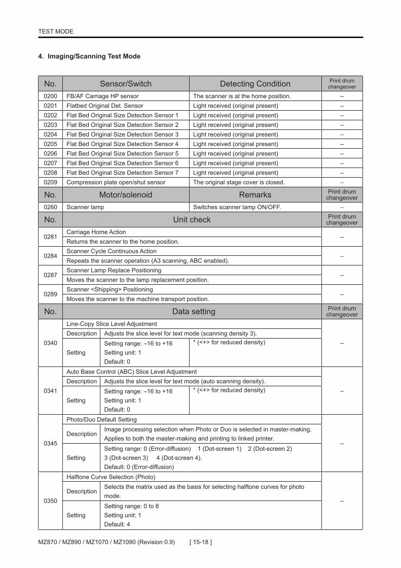
TEST MODE
No. Sensor/Switch Detecting Condition Print drum changeover
0200 FB/AF Carriage HP sensor The scanner is at the home position. –0201 Flatbed Original Det. Sensor Light received (original present) –0202 Flat Bed Original Size Detection Sensor 1 Light received (original present) –0203 Flat Bed Original Size Detection Sensor 2 Light received (original present) –0204 Flat Bed Original Size Detection Sensor 3 Light received (original present) –0205 Flat Bed Original Size Detection Sensor 4 Light received (original present) –0206 Flat Bed Original Size Detection Sensor 5 Light received (original present) –0207 Flat Bed Original Size Detection Sensor 6 Light received (original present) –0208 Flat Bed Original Size Detection Sensor 7 Light received (original present) –0209 Compression plate open/shut sensor The original stage cover is closed. –
No. Motor/solenoid Remarks Print drum changeover
0260 Scanner lamp Switches scanner lamp ON/OFF. –
No. Unit check Print drum changeover
0281Carriage Home Action
–Returns the scanner to the home position.
0284Scanner Cycle Continuous Action
–Repeats the scanner operation (A3 scanning, ABC enabled).
0287Scanner Lamp Replace Positioning
–Moves the scanner to the lamp replacement position.
0289Scanner <Shipping> Positioning
–Moves the scanner to the machine transport position.
No. Data setting Print drum changeover
0340
Line-Copy Slice Level Adjustment
–Description Adjusts the slice level for text mode (scanning density 3).
SettingSetting range: –16 to +16 Setting unit: 1 Default: 0
* (<+> for reduced density)
0341
Auto Base Control (ABC) Slice Level Adjustment
–Description Adjusts the slice level for text mode (auto scanning density).
SettingSetting range: –16 to +16 Setting unit: 1 Default: 0
* (<+> for reduced density)
0345
Photo/Duo Default Setting
–Description
Image processing selection when Photo or Duo is selected in master-making. Applies to both the master-making and printing to linked printer.
SettingSetting range: 0 (Error-diffusion) 1 (Dot-screen 1) 2 (Dot-screen 2) 3 (Dot-screen 3) 4 (Dot-screen 4). Default: 0 (Error-diffusion)
0350
Halftone Curve Selection (Photo)
–Description
Selects the matrix used as the basis for selecting halftone curves for photo mode.
SettingSetting range: 0 to 8 Setting unit: 1 Default: 4
4. Imaging/Scanning Test Mode
[ 15-19 ] MZ870 / MZ890 / MZ1070 / MZ1090 (Revision 0.9)
TEST MODE
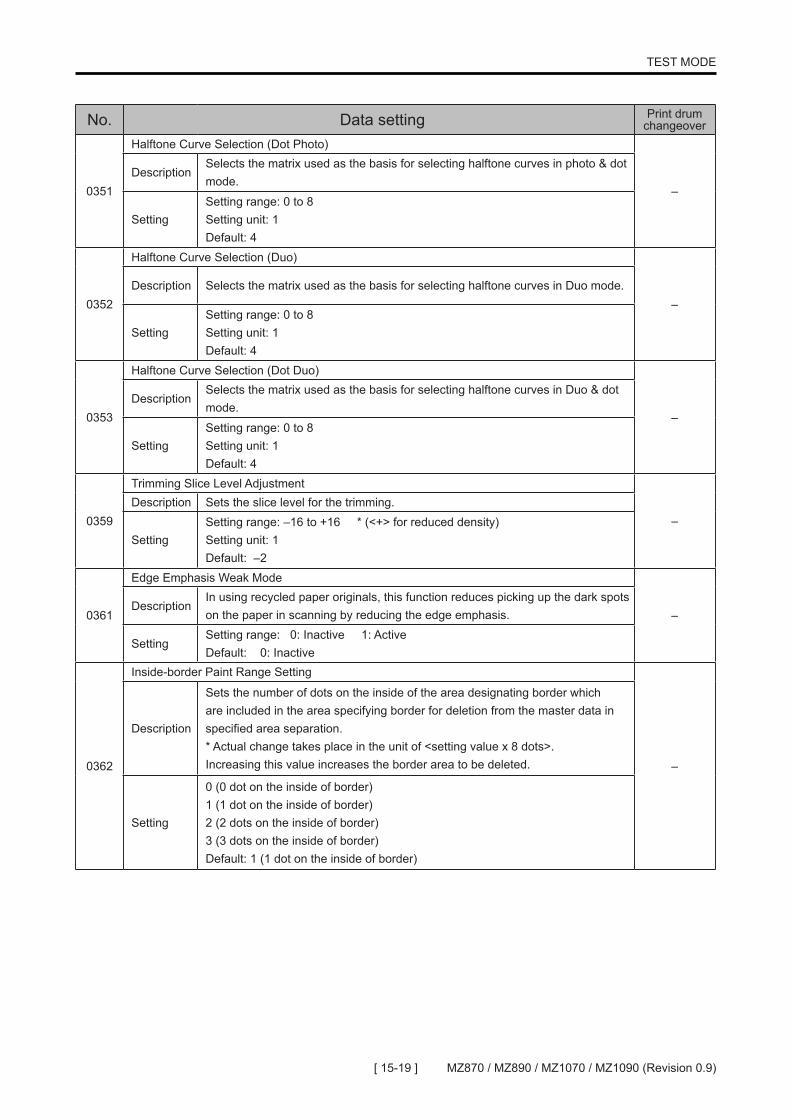
No. Data setting Print drum changeover
0351
Halftone Curve Selection (Dot Photo)
–Description
Selects the matrix used as the basis for selecting halftone curves in photo & dot mode.
SettingSetting range: 0 to 8 Setting unit: 1 Default: 4
0352
Halftone Curve Selection (Duo)
–Description Selects the matrix used as the basis for selecting halftone curves in Duo mode.
SettingSetting range: 0 to 8 Setting unit: 1 Default: 4
0353
Halftone Curve Selection (Dot Duo)
–Description
Selects the matrix used as the basis for selecting halftone curves in Duo & dot mode.
SettingSetting range: 0 to 8 Setting unit: 1 Default: 4
0359
Trimming Slice Level Adjustment
–Description Sets the slice level for the trimming.
SettingSetting range: –16 to +16 * (<+> for reduced density)Setting unit: 1Default: –2
0361
Edge Emphasis Weak Mode
–Description
In using recycled paper originals, this function reduces picking up the dark spots on the paper in scanning by reducing the edge emphasis.
SettingSetting range: 0: Inactive 1: ActiveDefault: 0: Inactive
0362
Inside-border Paint Range Setting
–
Description
Sets the number of dots on the inside of the area designating border which are included in the area specifying border for deletion from the master data in specified area separation. * Actual change takes place in the unit of <setting value x 8 dots>. Increasing this value increases the border area to be deleted.
Setting
0 (0 dot on the inside of border) 1 (1 dot on the inside of border) 2 (2 dots on the inside of border) 3 (3 dots on the inside of border)Default: 1 (1 dot on the inside of border)
[ 15-20 ]MZ870 / MZ890 / MZ1070 / MZ1090 (Revision 0.9)
TEST MODE
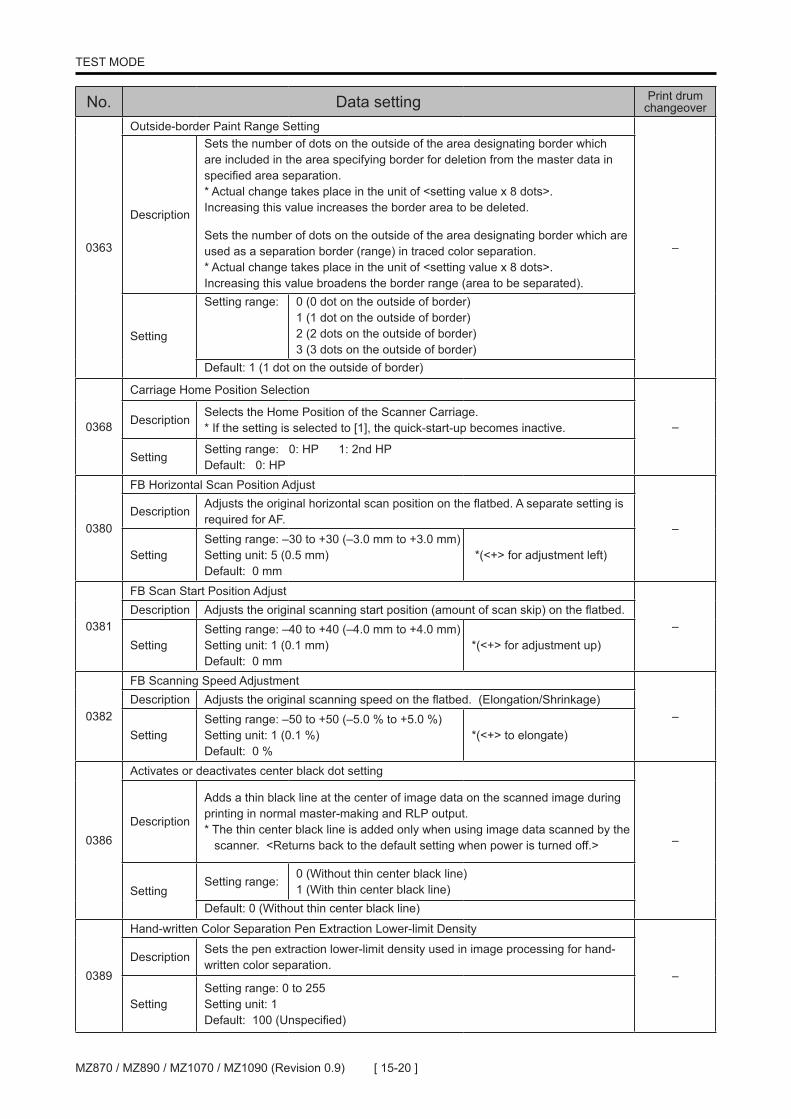
No. Data setting Print drum changeover
0363
Outside-border Paint Range Setting
–
Description
Sets the number of dots on the outside of the area designating border which are included in the area specifying border for deletion from the master data in specified area separation. * Actual change takes place in the unit of <setting value x 8 dots>. Increasing this value increases the border area to be deleted. Sets the number of dots on the outside of the area designating border which are used as a separation border (range) in traced color separation. * Actual change takes place in the unit of <setting value x 8 dots>. Increasing this value broadens the border range (area to be separated).
Setting
Setting range: 0 (0 dot on the outside of border) 1 (1 dot on the outside of border) 2 (2 dots on the outside of border) 3 (3 dots on the outside of border)
Default: 1 (1 dot on the outside of border)
0368
Carriage Home Position Selection
–DescriptionSelects the Home Position of the Scanner Carriage.* If the setting is selected to [1], the quick-start-up becomes inactive.
SettingSetting range: 0: HP 1: 2nd HPDefault: 0: HP
0380
FB Horizontal Scan Position Adjust
–Description
Adjusts the original horizontal scan position on the flatbed. A separate setting is required for AF.
SettingSetting range: –30 to +30 (–3.0 mm to +3.0 mm) Setting unit: 5 (0.5 mm) Default: 0 mm
*(<+> for adjustment left)
0381
FB Scan Start Position Adjust
–Description Adjusts the original scanning start position (amount of scan skip) on the flatbed.
SettingSetting range: –40 to +40 (–4.0 mm to +4.0 mm) Setting unit: 1 (0.1 mm) Default: 0 mm
*(<+> for adjustment up)
0382
FB Scanning Speed Adjustment
–Description Adjusts the original scanning speed on the flatbed. (Elongation/Shrinkage)
SettingSetting range: –50 to +50 (–5.0 % to +5.0 %) Setting unit: 1 (0.1 %) Default: 0 %
*(<+> to elongate)
0386
Activates or deactivates center black dot setting
–Description
Adds a thin black line at the center of image data on the scanned image during printing in normal master-making and RLP output. * The thin center black line is added only when using image data scanned by the scanner. <Returns back to the default setting when power is turned off.>
SettingSetting range:
0 (Without thin center black line) 1 (With thin center black line)
Default: 0 (Without thin center black line)
0389
Hand-written Color Separation Pen Extraction Lower-limit Density
–Description
Sets the pen extraction lower-limit density used in image processing for hand-written color separation.
SettingSetting range: 0 to 255 Setting unit: 1 Default: 100 (Unspecified)

[ 15-21 ] MZ870 / MZ890 / MZ1070 / MZ1090 (Revision 0.9)
TEST MODE
No. Data setting Print drum changeover
0390
Hand-written Color Separation Pen Extraction Upper-limit Density
–Description Sets the pen extraction upper-limit density used in image processing for hand-
written color separation.
SettingSetting range: 0 to 255 Setting unit: 1 Default: 220
0391
Hand-written Color Separation (Ink) Pen Extraction Lower-limit Density
–Description Sets the pen extraction lower-limit density used in image processing for hand-
written color separation (ink).
SettingSetting range: 0 to 255 Setting unit: 1 Default: 90
0392
Hand-written Color Separation (Ink) Pen Extraction Upper-limit Density
–Description Sets the pen extraction upper-limit density used in image processing for hand-
written color separation (ink).
SettingSetting range: 0 to 255 Setting unit: 1 Default: 180
0393
Red-color Separation Pen Extraction Lower-limit Density
–Description Sets the pen extraction lower-limit density used in image processing for red-color
separation.
SettingSetting range: 0 to 255 Setting unit: 1 Default: 100
0394
Red-color Separation Pen Extraction Upper-limit Density
–Description Sets the pen extraction upper-limit density used in image processing for red-
color separation.
SettingSetting range: 0 to 255 Setting unit: 1 Default: 220
0395
Specified Area Separation Density Extraction Threshold (Lower-limit Value)
–Description Sets the pen extraction lower-limit density used in image processing for specified
area separation.
SettingSetting range: 0 to 255 Setting unit: 1 Default: 125
0396
Specified Area Separation Density Extraction Threshold (Upper-limit Value)
–Description Sets the pen extraction upper-limit density used in image processing for specified
area separation.
SettingSetting range: 0 to 255 Setting unit: 1 Default: 220
0397
Traced Color Separation Density Extraction Threshold (Lower-limit Value)
–Description Sets the pen extraction lower-limit density used in image processing for traced
color separation.
SettingSetting range: 0 to 255 Setting unit: 1 Default: 100
0398
Traced Color Separation Density Extraction Threshold (Upper-limit Value)
–Description Sets the pen extraction upper-limit density used in image processing for traced
color separation.
SettingSetting range: 0 to 255 Setting unit: 1 Default: 255
0399
Edge Emphasis Threshold Offset
–Description Sets the offset for the following Test Mode setting value.
SettingSetting range: –128 to 127 Setting unit: 1 Default: 0

[ 15-22 ]MZ870 / MZ890 / MZ1070 / MZ1090 (Revision 0.9)
TEST MODE
No. Sensor/switch Detecting condition Print drum changeover
0400 Master-positioning sensor Light received (master detected) –0401 Master detection sensor Light path blocked (master detected) –0402 Master end sensor Light path blocked (master end mark detected) –0403 Cutter HP SW Switch OFF (cutter at home position) –0406 TPH pressure sensor Light path blocked (blocked by shield plate) –0407 Master-making-unit top cover safety switch Switch ON (master making unit top cover closed) –0410 Master-making-unit releasing button Switch ON (button depressed) –0411 Master-making Unit Position Sensor Light path blocked (blocked by shield plate) B0412 Master-making Unit Pull-out Position Sensor Light path blocked (blocked by shield plate) –
0413 Master-making Unit Drawer Cover Safety Switch
Switch ON (master making unit cover closed) * The rear cover safety SW must be ON during this procedure.
–
0420 Master-disposal Jam Sensor Light received (master detected) B
0421 Master-compression HP Sensor Light path blocked (master compression plate at home position) B
0423 Master-disposal box safety SW
Switch ON (master disposal box set in machine) * For inspections of the first print drum side, the rear cover safety switch and the master-making unit drawer cover safety switch must be ON during this procedure. * For inspections of the second print drum side, the rear cover safety switch, the master-making unit drawer cover safety switch, and the first master disposal box safety switch must be ON during this procedure.
B
0424 Master disposal box set sensor Light path blocked (disposal bix is set in place) B0425 Master-compression motor FG sensor Light path blocked (blocked by shield plate) B0426 Master-removal motor FG sensor Light path blocked (blocked by shield plate) B
No. Motor/solenoid Remarks Print drum changeover
0460 Thermal-pressure motor (CW) Rotates clockwise (CW). –0461 Thermal-pressure motor (CCW) Rotates counterclockwise (CCW). –0462 Write pulse motor (CW) Rotates clockwise (master feeding). –0463 Write pulse motor (CCW) Rotates counterclockwise (master returning). –0464 Load pulse motor (CW) Rotates clockwise (master feeding). –0465 Load Pulse Motor CCW (Reverse) Rotates counterclockwise (master returning). –
0466 Write pulse motor + Load pulse motor (CW) Rotate both write pulse motor and load pulse motor in master-feed direction. –
0467 Master-making-unit release button LED The LED of the master-making unit release button illuminates. –
0468 Master Stocker Fan ON & OFF <Stop Key = OFF> –0470 Master removal motor (CW) Rotates to feed master into the master disposal box. B
No. Unit check Print drum changeover
0480Cutter motor 1 cycle motion
–Cuts the master.
0481Thermal pressure motor action (TPH down)
–Moves the TPH to the pressure application position.
0482Thermal pressure motor action (TPH up)
–Moves the thermal print head to the pressure-releasing position (i.e., moves it out of the way).
0483Master-making Unit Positioning
BMoves master-making unit to the master-making position on the first or second print drum side.
0484Master-making Unit Pull-Out Position
–Moves the master-making unit to the pull-out position.
5. Master-making/Master-disposal Test Mode

[ 15-23 ] MZ870 / MZ890 / MZ1070 / MZ1090 (Revision 0.9)
TEST MODE
No. Unit check Print drum changeover
0490Master compression-plate home positioning
BReturns the compression plate to the home position.
0491Master compression-plate protection positioning
BMoves the master compression-plate to the Protection Mode position, when the Protection Mode is enabled.
0493Master compression-plate continuous movement
BRepeats the removed master compacting operation. A cycle consisting of compacting cycle action -> 3-second standby is repeated.
0494
Cutter motor ON action (cut direction)
–Rotates the cutter motor in the cutting direction. (maximum time: 10 sec)Caution: Disconnect the Cutter motor from the machine before activating this test
mode, or the machine will be damaged.
No. Data clear Details Print drum changeover
0510Master removal software count clear
Resets the master removal software count.(Resets the count to 0)
B
No. Data check Content of display Print drum changeover
0521TPH thermistor temperature data
Displays the temperature value (Degrees Celsius) of the TPH thermistor.
–
0524 TPH power voltageDisplays the voltage (x 100) applied to the thermal print head immediately after power is supplied to the thermal print head.(Example: 1000 = 10V)
–
0527 Master usage start date
Displays the master start date (year/month/date) stored in the master tag. * For example, <2010/2/28> is displayed by alternating indications of <2010> and <0228>.
–
0528Master removal software count
Displays the master removal software count. B
No. Data setting Print drum changeover
0540
Master Front-End Position Adjust
–Description
Adjusts the distance of the slight return movement activated after the master positioning sensor switches OFF to perform the incremental movement required following the master cutting operation during master setting.
SettingSetting range: 0 to +100 (0 mm to +10.0 mm) * (<+> for return direction) Setting unit: 1 (0.1 mm) Default: 50 (5.0 mm)
0541
Write start-position adjustment
–Description
Adjusts the master-making start position. (Adjusts the master stop position immediately before write start operation by modifying the distance of the return movement from the master positioning sensor.)
SettingSetting range: –50 to +50 (–5.0 mm to +5.0 mm) * (<+> for adjustment up) Setting unit: 1 (0.1 mm) Default: 0 (0 mm)
0542
Master-making length adjustment
–
Description Adjusts the master-making area (length).
Setting
Setting range: –100 to +100 (–10.0 mm to +10.0 mm) * (<+> to increase length) Setting unit: 1 (0.1 mm) Default: 0 (0 mm)

[ 15-24 ]MZ870 / MZ890 / MZ1070 / MZ1090 (Revision 0.9)
TEST MODE
No. Data setting Print drum changeover
0543
Master-clamp-range adjustment
BDescription Adjusts the master clamp range during master-loading.
SettingSetting range: –100 to +100 (–10.0 mm to +10.0 mm) * (<+> to increase) Setting unit: 1 (0.1 mm) Default: 0 (0 mm)
0544
Master cut length adjustment
BDescription Adjusts the length of a single master (cutting timing).
Setting
Setting range: –100 to +100 (–10.0° to +10.0°) Setting unit: 5 (0.5°) * (1°= approx. 1.5 mm, <+> for increased master length) Default: 0 (0°)
0545
TPH Thermal Power Adjustment
–Description Adjusts the TPH power.
SettingSetting range: 0 to 8 * (Smaller the number the higher the TPH power)Default: MZ8/MV8 = 2 MZ10/MV10 = 4
No. Data setting Print drum changeover
0547
Master-making speed adjustment
BDescription
Regulates the speed of the write pulse motor to adjust image stretching/shrinkage during master-making.
SettingSetting range: –100 to +100 (–10.0% to +10.0%) * (<+> to elongate) Setting unit: 1 (0.1%) Default: 3 (0.3%)
0548
Write Roller Diameter Reference Adjustment
–
DescriptionInput the diameter of the Write roller to compensate the fluctuation in diameter between the rollers.
Setting
Setting range:2305 (23.05mm) to 2315 (23.15mm) * (input the diameter in millimeters x 100) Setting unit: 1 (0.01mm) Default: 2310 (23.10mm)
0550
Master-making Unit Adjustment
BDescription Adjusts the master-making unit stop position for master-making.
SettingSetting range: –20 to +20 (–2.0 mm to +2.0 mm) Setting unit: 1 (0.1 mm) Default: 10 (1.0 mm)
0551
Master-making Unit Pull-Out Position Adjustment
–Description Adjusts the master-making unit stop position for removal.
SettingSetting range: –20 to +20 (–2.0 mm to +2.0 mm) Setting unit: 1 (0.1 mm) Default: 0 (0 mm)
0570
M.-Rmv. Roller Stop Timing
BDescription Sets the timing for vertical transport rollers to stop in relation to print drum angle.
SettingSetting range: –50 to +50 (–50 degrees to +50 degrees) Setting unit: 1 (1 degree) Default: No.1 Drum = 0 (0 degree) No.2 Drum = 30 (30 degrees)

[ 15-25 ] MZ870 / MZ890 / MZ1070 / MZ1090 (Revision 0.9)
TEST MODE
No. Data setting Print drum changeover
0572
Master Removal Box Set-Motion
–Description
Activates or deactivates the master removal box set-motion when the machine power is turned, when the machine wakes up from sleep mode or when the box is inserted.
SettingSetting range: 0 (Deactivated) 1 (Activated). Default: 0 (Deactivated)
0573
Master compression-limit position (maximum end position)
B
Description Sets the pulse count for the compacting limit position.
Setting
Setting range: 106 to 163 (106 to 163 pulses) (Compression plate angle from home position: 65° to 100°)Setting unit: 1 (1 pulse) Default: A3/Ledger = 155 / Other sizes = 147
0575
Master compression duration adjustment
BDescription
Sets the time (time for single cycle of compacting FG) for the detection of compacting. * The compacting operation finishes when the one cycle time of the compacting FG exceeds the set time.
Setting
Setting range: 500 to 7000 (5 msec to 70 msec) Setting unit: 25 (0.25 msec)Default: 4000 (40 msec)
0576
Master disposal box full detection position adjustment
B
Description Sets the pulse count for the full box compacting position.
Setting
Setting range: 100 to 162 (100 to 162 pulses) Setting unit: 1 (1 pulse) Default: A3/Ledger Drum = 120 pulses <MZ8/MV8> A3/Ledger Drum = 110 pulses <MZ10/MV10> B4/Legal Drum = 146 pulses <MZ8/MV8 & MZ10/MV10>
0577
Master Compression PROTECT Position Adjustment
BDescription
Adjusts the position of the Master compression plate when the PROTECT is ON.
Setting
Setting range: -30 to +30 (-30 pulses to +30 pulses)Setting unit: 5 (5 pulses) Default: 0 <39.6° from the HP position.)
0578
Master disposal motor speed selection
B
DescriptionSelects the master disposal motor speed table relative to master removal print drum speed.
Setting
Setting range: 0 (0.9 times the speed) 1 (1.0 times the speed) 2 (1.1 times the speed) 3 (1.2 times the speed) 4 (1.3 times the speed)
Default: No 1 Drum = 2 No 2 Drum = 1
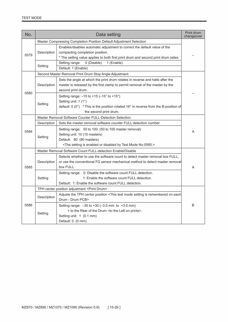
[ 15-26 ]MZ870 / MZ890 / MZ1070 / MZ1090 (Revision 0.9)
TEST MODE
No. Data setting Print drum changeover
0579
Master Compressing Completion Position Default Adjustment Selection
–Description
Enables/disables automatic adjustment to correct the default value of the compacting completion position. * The setting value applies to both first print drum and second print drum sides.
SettingSetting range: 0 (Disable) 1 (Enable)Default: 1 (Enable)
0580
Second Master Removal Print Drum Stop Angle Adjustment
–
DescriptionSets the angle at which the print drum rotates in reverse and halts after the master is released by the first clamp to permit removal of the master by the second print drum.
Setting
Setting range: –15 to +15 (–15° to +15°) Setting unit: 1 (1°) default: 0 (0°) * This is the position rotated 16° in reverse from the B-position of the second print drum.
0584
Master Removal Software Counter FULL-Detection Selection
A
Description Sets the master removal software counter FULL detection number.
Setting
Setting range: 50 to 100 (50 to 100 master removal) Setting unit: 10 (10 masters) Default: 80 (80 masters) <The setting is enabled or disabled by Test Mode No.0585.>
0585
Master Removal Software Count FULL-detection Enable/Disable
ADescription
Selects whether to use the software count to detect master removal box FULL, or use the conventional FG sensor mechanical method to detect master removal box FULL.
SettingSetting range: 0: Disable the software count FULL detection. 1: Enable the software count FULL detection. Default: 1: Enable the software count FULL detection.
0586
TPH center position adjustment <Print Drum>
B
DescriptionAdjusts the TPH center position <This test mode setting is remembered on each Drum - Drum PCB>
Setting
Setting range: –30 to +30 (–3.0 mm to +3.0 mm) + to the Rear of the Drum <to the Left on prints>. Setting unit: 1 (0.1 mm) Default: 0 (0 mm)

[ 15-27 ] MZ870 / MZ890 / MZ1070 / MZ1090 (Revision 0.9)
TEST MODE
No. Sensor/switch Detecting condition Print drum changeover
0600 Paper detection sensor Light received (paper detected) –0601 Paper-length detection sensor Light received (paper detected) –0602 Elevator upper-limit sensor A Light path blocked (blocked by shield plate) –0603 Elevator upper-limit sensor B Light path blocked (blocked by shield plate) –0604 Elevator lower-limit sensor Light path blocked (blocked by shield plate) –0605 Paper sensor Light path blocked (paper detected) –0606 Paper-ejection sensor Light received (paper detected) –0607 Paper-feed-tray upper safety SW ON (Safety switch not triggered.) –0608 Paper-feed-tray lower safety SW ON (Safety switch not triggered.) –0609 Paper-feed tray elevation button Switch ON (button depressed) –0610 Remaining Paper Volume Sensor A Light path blocked (blocked by shield plate) –0611 Remaining Paper Volume Sensor B Light path blocked (blocked by shield plate) –0612 Paper-ejection FG sensor Light path blocked (blocked by shield plate) –
0613Card feeder (Option) attachment detection
Light path blocked (Card feeder detected)
0614 Paper-feed pressure sensor Light path blocked (Lever to the Card) –0615 Registration Sensor Light path blocked (paper detected) –
0616Guide Roller Release Home Position Sensor
Light path blocked (blocked by shield plate) –
0617 Central Transport Sensor Light path blocked (paper detected) –
0618Paper Ejection Wing Home Position Sensor
Light path blocked (blocked by shield plate) –
0619Second Paper Feed Motor FG Sensor
Light path blocked (blocked by shield plate) –
0620 Central Flap Home Position Sensor Light path blocked (blocked by shield plate) –
No. Motor/solenoid Remarks Print drum changeover
0660 Paper ejection motor ON & OFF <Stop Key = OFF> –0661 Suction fan ON & OFF <Stop Key = OFF> –0662 Separation fan ON & OFF <Stop Key = OFF> (All safety SW must be ON) –0663 Second Paper Feed Motor ON & OFF <Stop Key = OFF> –0664 Central Suction Fan ON & OFF <Stop Key = OFF> –0665 First Separation Fan ON & OFF <Stop Key = OFF> –
0666Paper Ejection Wing Pulse Motor (CW)
ON & OFF <Stop Key = OFF> –
0667Paper Ejection Wing Pulse Motor (CCW)
ON & OFF <Stop Key = OFF> –
0668 Feed Tray Button LED The LED illuminates. –
6. Paper-feed/Paper-eject Test Mode

[ 15-28 ]MZ870 / MZ890 / MZ1070 / MZ1090 (Revision 0.9)
TEST MODE
No. Unit check Print drum changeover
0681Paper feed tray maximum up positioning
–Raises the paper feed tray to the paper feed position when the Start key is pressed.
0682Paper feed tray elevation up & down
–Repeats the paper feed tray raising and lowering operations.
0683Paper feed tray maximum down positioning
–Lowers the paper feed tray to the lower-limit position when the Start key is pressed.
0684Separation Pump Solenoid ON/OFF Action
BTurns the solenoid ON when the Start key is pressed. The solenoid automatically switches OFF after 10 seconds.
0687Paper Feed Reverse-rotation Prevention Solenoid ON/OFF Action
–Turns the solenoid ON when the Start key is pressed. The solenoid automatically switches OFF after 10 seconds.
0688Paper-feed clutch ON/OFF action
–Turns the clutch ON when the Start key is pressed. The clutch automatically switches OFF after 10 seconds.
0702Guide Roller Release Motor
–Repeats nipping and releasing operations when the Start key is pressed.
0703Paper Ejection Wing Home Action
–Moves the paper ejection wings to the home positions.
0704Paper Ejection Wing Target Shift
–Moves the wings to the positions set in Test Mode No. 780.
0705Multiple Paper Feed Detection Sensor Sensitivity Automatic Adjustment
–One sheet of thin RISO paper must be set at the multiple paper feed sensor position during this procedure.
0707Central Flap Motor (Normal)
–Repeats the flat movement between the up and down positions when the Start key is pressed.
0708
Elevator motor ON action
–Rotates the elevator motor for raising operation (maximum time: 10 sec).Caution: Disconnect the Elevator motor from the machine before activating this test mode, or the machine will be damaged.
0709Registration Sensor Sensitivity Automatic Adjustment
–One sheet of thin RISO paper must be set at the registration sensor position during this procedure.
0721 Paper width potentiometer dataDisplays the paper width (mm) to the first decimal place after adjustment.
–
0722 Multiple Paper Feed SensorDisplays the A/D value of the multiple paper feed sensor (paper sensor).
–
0723 Registration Sensor Displays the A/D value of the registration sensor. –
No. Data setting Print drum changeover
0740
Elevator upper-limit position selection
–
DescriptionSelects the paper feed tray stop position (paper feed position). In the case of <Auto>, the upper-limit position is linked to the paper feed pressure lever position. The position is fixed in settings <1> through <3>.
Setting
Setting range: 0 (Auto. Linked to paper feed pressure lever position) 1 (Normal position) 2 (Card position) 3 (Custom position) Default: 0 (Auto. Linked to paper feed pressure lever position)

[ 15-29 ] MZ870 / MZ890 / MZ1070 / MZ1090 (Revision 0.9)
TEST MODE
No. Data setting Print drum changeover
0741
Paper-feed-clutch ON angle
–
Description Sets the activation angle for the paper feed clutch.
Setting
Setting range: –200 to +200 (–20.0° to +20.0°) * (<+> for slower ON timing) Setting unit: 5 (0.5°) Default: 0 (0°)
0742
Paper-feed-clutch OFF angle
–
DescriptionSets the deactivation angle for the paper feed clutch when the paper type is normal.
Setting
Setting range: –200 to +200 (–20.0° to +20.0°) * (<+> for slower OFF timing) Setting unit: 5 (0.5°) Default: 0 (0°)
0744
Paper Feed Clutch OFF Angle (card)
–
DescriptionSets the deactivation angle for the paper feed clutch when the paper type is <CARD>.
Setting
Setting range: –200 to +200 (–20.0° to +20.0°) * (<+> for slower OFF timing) Setting unit: 5 (0.5°) Default: 0 (0°)
0749
FP Paper Feed Clutch ON Angle
–Description Sets the activation angle for the paper feed clutch for proof print.
SettingSetting range: –100 to +100 (–10.0° to +10.0°) * <+> for slower ON timing Setting unit: 5 (0.5°) Default: 0 (0°)
0750
Paper feed reverse-rotation prevention solenoid Activate/Deactivate selection.
–Description Activates or Deactivates the Paper feed reverse-rotation prevention solenoid.
SettingSetting range: 0: Deactivates the solenoid. 1: Activates the solenoid.Default: 1: Activates the solenoid.<Paper Feed Pressure Lever must be selected to Card to activate the solenoid.>
0751
Paper feed jam detection angle. (Paper IN)
–
Description Sets the detection angle for paper feed jam (paper feed IN).
Setting
Setting range: –200 to +200 (–20.0° to +20.0°) * <+> for slower detection timing Setting unit: 5 (0.5°) Default: 0 (0°)
0752
Paper feed jam detection angle. (Paper OUT)
–
Description Sets the detection angle for paper feed jam (paper feed OUT).
Setting
Setting range: –200 to +200 (–20.0° to +20.0°) * <+> for slower detection timing Setting unit: 5 (0.5°) Default: 0 (0°)
0753
Paper receiving jam detection angle. (Paper IN)
–
Description Sets the detection angle for paper ejection jam (paper ejection IN).
Setting
Setting range: –500 to +500 (–50.0° to +50.0°) * (<+> for slower detection timing) Setting unit: 5 (0.5°) Default: 0 (0°)
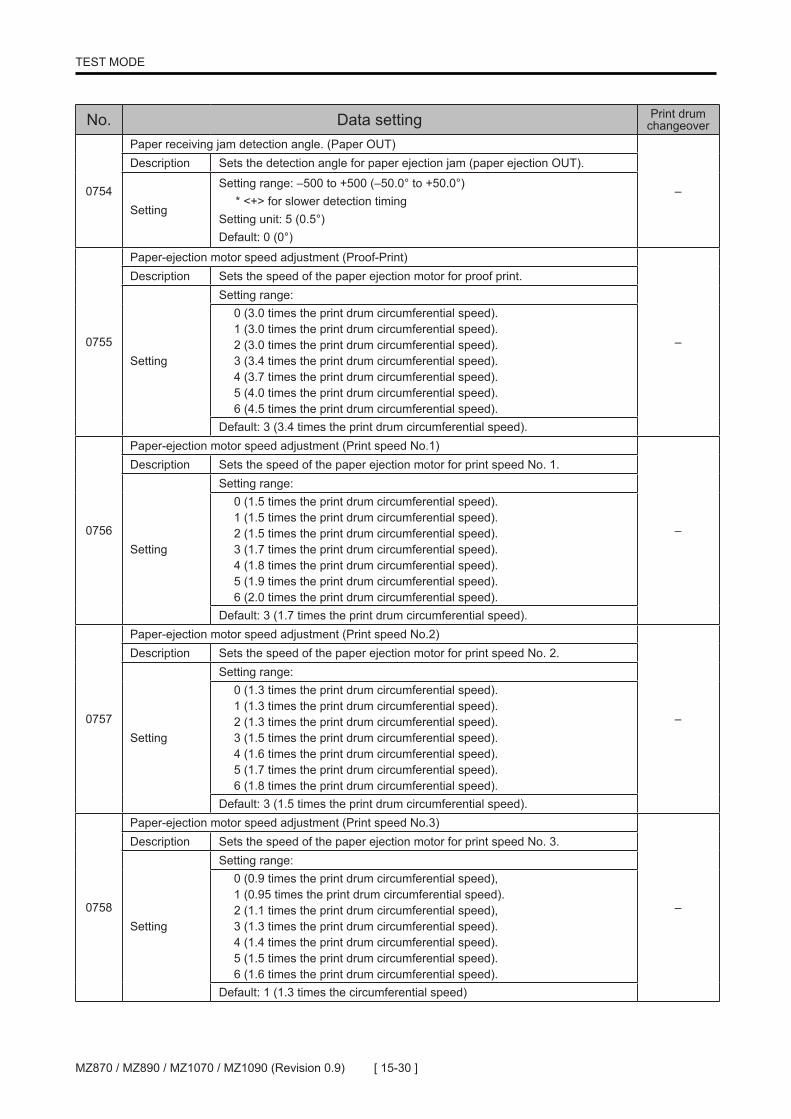
[ 15-30 ]MZ870 / MZ890 / MZ1070 / MZ1090 (Revision 0.9)
TEST MODE
No. Data setting Print drum changeover
0754
Paper receiving jam detection angle. (Paper OUT)
–
Description Sets the detection angle for paper ejection jam (paper ejection OUT).
Setting
Setting range: –500 to +500 (–50.0° to +50.0°) * <+> for slower detection timing Setting unit: 5 (0.5°) Default: 0 (0°)
0755
Paper-ejection motor speed adjustment (Proof-Print)
–
Description Sets the speed of the paper ejection motor for proof print.
Setting
Setting range:0 (3.0 times the print drum circumferential speed).1 (3.0 times the print drum circumferential speed). 2 (3.0 times the print drum circumferential speed).3 (3.4 times the print drum circumferential speed). 4 (3.7 times the print drum circumferential speed).5 (4.0 times the print drum circumferential speed). 6 (4.5 times the print drum circumferential speed).
Default: 3 (3.4 times the print drum circumferential speed).
0756
Paper-ejection motor speed adjustment (Print speed No.1)
–
Description Sets the speed of the paper ejection motor for print speed No. 1.
Setting
Setting range:0 (1.5 times the print drum circumferential speed).1 (1.5 times the print drum circumferential speed). 2 (1.5 times the print drum circumferential speed). 3 (1.7 times the print drum circumferential speed). 4 (1.8 times the print drum circumferential speed). 5 (1.9 times the print drum circumferential speed). 6 (2.0 times the print drum circumferential speed).
Default: 3 (1.7 times the print drum circumferential speed).
0757
Paper-ejection motor speed adjustment (Print speed No.2)
–
Description Sets the speed of the paper ejection motor for print speed No. 2.
Setting
Setting range:0 (1.3 times the print drum circumferential speed).1 (1.3 times the print drum circumferential speed). 2 (1.3 times the print drum circumferential speed).3 (1.5 times the print drum circumferential speed). 4 (1.6 times the print drum circumferential speed).5 (1.7 times the print drum circumferential speed). 6 (1.8 times the print drum circumferential speed).
Default: 3 (1.5 times the print drum circumferential speed).
0758
Paper-ejection motor speed adjustment (Print speed No.3)
–
Description Sets the speed of the paper ejection motor for print speed No. 3.
Setting
Setting range:0 (0.9 times the print drum circumferential speed),1 (0.95 times the print drum circumferential speed). 2 (1.1 times the print drum circumferential speed),3 (1.3 times the print drum circumferential speed). 4 (1.4 times the print drum circumferential speed).5 (1.5 times the print drum circumferential speed). 6 (1.6 times the print drum circumferential speed).
Default: 1 (1.3 times the circumferential speed)

[ 15-31 ] MZ870 / MZ890 / MZ1070 / MZ1090 (Revision 0.9)
TEST MODE
No. Data setting Print drum changeover
0759
Paper-ejection motor speed adjustment (Print speed No.4)
–
Description Sets the speed of the paper ejection motor for print speed No. 4.
Setting
Setting range:
0 (0.9 times the print drum circumferential speed).1 (0.9 times the print drum circumferential speed). 2 (1.0 times the print drum circumferential speed).3 (1.1 times the print drum circumferential speed). 4 (1.2 times the print drum circumferential speed).5 (1.3 times the print drum circumferential speed). 6 (1.4 times the print drum circumferential speed).
Default: 4 (1.2 times the print drum circumferential speed).
0760
Paper-ejection motor speed adjustment (Print speed No.5)
–
Description Sets the speed of the paper ejection motor for print speed No. 5.
Setting
Setting range:
0 (0.9 times the print drum circumferential speed).1 (0.95 times the print drum circumferential speed). 2 (1.0 times the print drum circumferential speed). 3 (1.1 times the print drum circumferential speed). 4 (1.2 times the print drum circumferential speed).5 (1.3 times the print drum circumferential speed). 6 (1.4 times the print drum circumferential speed).
Default: 4 (1.2 times the print drum circumferential speed).
0761
High-speed printing paper ejection motor speed selection.
–
Description Sets the speed of the paper ejection motor for high-speed printing.
Setting
Setting range:
0 (0.9 times the print drum circumferential speed). 1 (0.95 times the print drum circumferential speed). 2 (1.0 times the print drum circumferential speed). 3 (1.1 times the print drum circumferential speed). 4 (1.2 times the print drum circumferential speed). 5 (1.3 times the print drum circumferential speed). 6 (1.4 times the print drum circumferential speed).
Default: 3 (1.1 times the print drum circumferential speed).
0777
Print drum acceleration control selection
–DescriptionSelection of the print drum acceleration when the printing starts. The choice of 10 rpm acceleration per one drum rotation, or stepless acceleration.
Setting Setting range: 0: Accelerates in steps 1: Stepless acceleration
0779
Paper Ejection Wing Position Adjustment
–Description Sets the adjustment value for the amount of paper ejection wing motion.
SettingSetting range: –20 to +20 (–20 to +20 pulses) Setting unit: 1 (1 pulse) Default: 0 (0 pulse)

[ 15-32 ]MZ870 / MZ890 / MZ1070 / MZ1090 (Revision 0.9)
TEST MODE
No. Data setting Print drum changeover
0780
Paper Ejection Wing Target Position
–Description
Sets the positions of the paper ejection wings when the custom paper ejection position is selected. This setting is reflected in the operation set in Test Mode No. 704.
SettingSetting range: 0 to 2150 (0 to 2150 pulses) Setting unit: 1 (1 pulse) Default: 1434 (1434 pulses)
0781
Central Transport Jam Angle/IN
–
DescriptionAdjusts the detection angle for paper input jams for the central transport sensor.
Setting
Setting range: –200 to +200 (–20.0° to +20.0°) * (<+> for slower detection timing) Setting unit: 5 (0.5°) Default: 0 (0°)
0782
Central Transport Jam Angle/OUT
–
DescriptionAdjusts the detection angle for paper output jams for the central transport sensor.
Setting
Setting range: –200 to +200 (–20.0° to +20.0°) * (<+> for slower detection timing) Setting unit: 5 (0.5°) Default: 0 (0°)
0786
Second Paper Feed Speed Ratio (for all area)
BDescription Changes the speed of the timing roller.
SettingSetting range: -20 to +20 (-2.0% to +2.0%) Setting unit: 2 (0.2%) Default: 0 (0.0%)
0787
Second Paper Feed Speed Ratio (for first 160mm of the paper)
–Description
Changes the speed of the timing roller fo the distance of 160mm from the leading edge for each paper.
SettingSetting range: -20 to +20 (-2.0% to +2.0%) Setting unit: 2 (0.2%) Default: 0 (0.0%)
0788
Paper Feeder Active/Inactive Selection
–Description
Allows master making and printing action without Paper feed tray movement. The selected setting is not stored. The setting returns to the default once the machine goes out of test mode.
SettingSetting range: 0: Inactive 1: Active Default: 0: Inactive
0793
Second Separation Fan Control in Printing with No.1 Print Drum Only
–Description
Selects whether to activate or deactivate the Separation fan for the No.2 print drum when printing with only No1 print drum.
SettingSetting range: 0: OFF (No.2 Separation fan stays OFF) 1: ON (No.2 Separation fan stays ON) Default: 0: OFF (No.2 Separation fan stays OFF)

[ 15-33 ] MZ870 / MZ890 / MZ1070 / MZ1090 (Revision 0.9)
TEST MODE
No. Sensor/switch Detecting condition Print drum changeover
0801 Position-B sensor Light path blocked (blocked by shield plate) B0802 Main-motor FG sensor Light path blocked (blocked by shield plate) –0803 Clamp sensor A Light path blocked (blocked by shield plate) B0804 Clamp sensor B Light path blocked (blocked by shield plate) –0805 Print Drum FG Sensor Light path blocked (blocked by shield plate) B0806 Master loading sensor Light received (master detected) B0807 Print-drum lock-position sensor Light path blocked (blocked by shield plate) B0808 Drive Lock Release Sensor Light path blocked (blocked by shield plate) B0809 Ink sensor In contact with ink B0810 Overflow sensor In contact with ink B0811 Ink-cartridge set SW Switch ON (button depressed) B0812 Ink pump FG sensor Light path blocked (blocked by shield plate) B0816 Drum free rotation SW Switch ON (button depressed) –0818 Print-drum release button Switch ON (button depressed) –
0819 Print-drum connection signal The print drum is connected to the main unit drawer connector. B
0820 Print-drum safety switch Switch ON (print drum set in machine) B0821 Front Cover Safety SW Switch ON (front cover closed) –0830 Print-Pressure HP Sensor Light path blocked (blocked by shield plate) B0832 Horizontal Home Position Sensor Light path blocked (blocked by shield plate) B
No. Motor/solenoid Remarks Print drum changeover
0861 Main-motor action (30 rpm) Main motor stops when STOP key is pressed. –0863 Clamp-motor action (Normal direction) CCW (counterclockwise rotation) B0864 Clamp-motor action (Opposite direction) CW (clockwise rotation) B0866 Print-drum release SW (button) The LED illuminates. –0867 Print-drum brake fan ON / OFF <Stop key = OFF> –
No. Unit check Print drum changeover
0880Variable print-drum rotation
– Rotates the print drum with the Speed selection key enabled.
0881Position-A action of the print drum
B Stops the print drum at position A.
0882
Inking motor ON action
B Operates the inking motor (maximum time: 1 sec).Caution: Disconnect the inking motor from the machine before activating this test mode, or the machine will be damaged.
0883Clamp home positioning action
B Returns the clamp unit to the home position.
0884
Clamp unit cycle action (3 step cycle)
B
Caution: Prior to executing this test mode, bring the Print Drum to Position-A by Test Mode No. 881, and to Clamp home position by Test Mode No. 883, otherwise the machine will be damaged.
Pressing the Start key once performs a single cycle of the following operations: << First clamp unit >> Step 1: Clamp home position –> Clamp open Step 2: Clamp open Position A adjustment Step 3: Position A adjustment –> Clamp closed (clamp at home position) << Second clamp unit >> Step 1: Clamp home position –> Clamp open Step 2: Clamp open –> Clamp closed (clamp at home position)
7. Print Drum/ Print Adjustment Test Mode
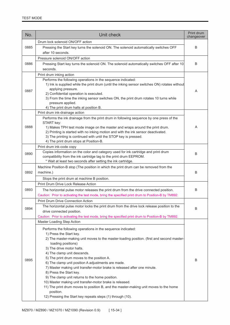
[ 15-34 ]MZ870 / MZ890 / MZ1070 / MZ1090 (Revision 0.9)
TEST MODE
No. Unit check Print drum changeover
0885Drum lock solenoid ON/OFF action
B Pressing the Start key turns the solenoid ON. The solenoid automatically switches OFF after 10 seconds.
0886Pressure solenoid ON/OFF action
B Pressing Start key turns the solenoid ON. The solenoid automatically switches OFF after 10 seconds.
0887
Print drum inking action
A
Performs the following operations in the sequence indicated: 1) Ink is supplied while the print drum (until the inking sensor switches ON) rotates without applying pressure. 2) Confidential operation is executed. 3) From the time the inking sensor switches ON, the print drum rotates 10 turns while pressure applied. 4) The print drum halts at position B.
0888
Print drum ink-drainage action
A
Performs the ink drainage from the print drum in following sequence by one press of the START key: 1) Makes TPH test mode image on the master and wraps around the print drum. 2) Printing is started with no inking motion and with the ink sensor deactivated. 3) The printing is continued with until the STOP key is pressed. 4) The print drum stops at Position-B.
0890
Print drum ink-code copy
B Copies information on the color and category used for ink cartridge and print drum compatibility from the ink cartridge tag to the print drum EEPROM. * Wait at least two seconds after setting the ink cartridge.
0892Machine Position-B stop (The position in which the print drum can be removed from themachine.) B
Stops the print drum at machine B position.
0893Print Drum Drive Lock Release Action
B The horizontal pulse motor releases the print drum from the drive connected position.Caution: Prior to activating the test mode, bring the specified print drum to Position-B by TM892.
0894
Print Drum Drive Connection Action
B The horizontal pulse motor locks the print drum from the drive lock release position to the drive connected position.Caution: Prior to activating the test mode, bring the specified print drum to Position-B by TM892.
0895
Master Loading Step Action
B
Performs the following operations in the sequence indicated: 1) Press the Start key. 2) The master-making unit moves to the master-loading position. (first and second master- loading positions) 3) The drive motor halts. 4) The clamp unit descends. 5) The print drum moves to the position A. 6) The clamp unit position A adjustments are made. 7) Master making unit transfer-motor brake is released after one minute. 8) Press the Start key. 9) The clamp unit returns to the home position. 10) Master making unit transfer-motor brake is released. 11) The print drum moves to position B, and the master-making unit moves to the home position. 12) Pressing the Start key repeats steps (1) through (10).

[ 15-35 ] MZ870 / MZ890 / MZ1070 / MZ1090 (Revision 0.9)
TEST MODE
No. Unit check Print drum changeover
0896
Print Drum Free Rotation
– Rotates the print drum at 10 rpm. The rear cover safety SW must be pressed (buzzer will sound until the safety SW is pressed). To stop the drum rotation, press the Stop Key or release the Rear cover safety switch.
0899Master Making Unit Position-A Movement.
– Press Start Key for each Master Making Unit movement.
0900Vertical-centering action
– Brings the vertical print positioning motor to the HP position.
0901Vertical print position one cycle action
– Operates the vertical print positioning motor to one extreme to the other and stops at HP position..
0902Print Drum Horizontal Home Action
B Returns the print drum horizontal position to the center (home position).
0903Print Drum Horizontal Cycle Action
B Performs a single horizontal movement cycle.
0904Print-pressure home positioning
B Returns the pressure control unit to the home position.
0905Print-pressure one cycle action
B Performs a single print pressure control cycle.
0906
Pressure Roller Maintenance Position
B Pressing the Start key raises the pressure roller. * This operation is activated only if the Start key is pressed with the print drum removed and the front cover closed.
0907
Pressure Roller Maintenance Positioning
– Pressing the Start key lowers the pressure roller. * This operation is activated only if the Start key is pressed with the print drum removed and the front cover closed.
0908Print-pressure maintenance positioning
B Operates the pressure control pulse motor until the pressure spring removal position (-8130 pulses) is reached.
No. Data check Content of display Print drum changeover
0921 Print-drum angle display Displays the current print drum angle (x 10). B
0923 Print-drum ink temperature display Displays the temperature value (°C) converted from the A/D value of the ink thermistor. B
0925 Ink remaining volume displayDisplays the amount of ink left in the ink cartridge as a percent (%) value read from the ink cartridge tag.
B
0926 Ink motor FG count Displays the inking motor FG count value read from the ink cartridge tag. (1 count = 0.1 ml) B
0928 Displays the Ink use starting date.
Displays the ink use start date stored in the ink cartridge tag. * For example, <2010/2/28> is displayed by alternating indications of <2010> and <0228>.
B
0929 Main motor offset voltage informationDisplays the main motor offset voltage information acquired by test mode adjustment No.1105.
–

[ 15-36 ]MZ870 / MZ890 / MZ1070 / MZ1090 (Revision 0.9)
TEST MODE
No. Data check Content of display Print drum changeover
0930 Main motor setting informationDisplays the main motor setting information acquired by test mode adjustment No.1105.
–
0931Second paper feed motor offset voltage information
Displays the second paper feed motor offset voltage information acquired by test mode adjustment No.1106.
–
0932 Second paper feed motor setting informationDisplays the second paper feed motor setting information acquired by test mode adjustment No.1106.
–
No. Data setting Print drum changeover
0940
Master loading sensor detection timing adjustment
BDescription Adjusts the master-loading detection angle.
Setting
Setting range: –200 to +100 (–20.0° to +10.0°) Setting unit: 5 (0.5°) Default: 0 (0°)
* (<+> for slower detection timing)
0941
Print-drum Position-A adjustment
B
Description Adjusts the print drum position-A stop position.
Setting
Setting range: MZ8: –40 to +40 (–4.0° to +4.0°) MZ10: -60 to +40 (–6.0° to +4.0°) Setting unit: MZ8: 5 (0.5°) MZ10: 1 (0.1°) Default: MZ8 Drum No.1: 10 (1.0°) MZ8 Drum No.2: 0 (0°) MZ10 Drum No.1: -25 (-2.5°) MZ10 Drum No.2: -35 (-3.5°)
* (<+> for overrun)
0942
Print-drum position-B adjustment
BDescription Adjusts the print drum position-B stop position.
SettingSetting range: –40 to +40 (–4.0° to +4.0°) Setting unit: 5 (0.5°) Default: 0 (0°)
* (<+> for overrun)
0943
Inking time adjustment (when over X% of ink is consumed from the ink tube.)
BDescription
Sets the continuous ink sensor OFF detection time that prompts the inkless detection signal if the amount of ink consumed exceeds a set percent value (value set in Test Mode No. 948) (data stored in print drum PCB).
SettingSetting range: 5 to 60 (5 to 60 sec) Setting unit: 1 (1 sec) Default: 10 (10 sec)
0944
Inking time adjustment (right after the ink tube is replaced)
BDescription
Sets the continuous ink sensor OFF detection time that prompts the inkless detection signal after ink cartridge replacement (data stored in print drum PCB). * This information is recorded in the print drum EEPROM.
SettingSetting range: 5 to 60 (5 to 60 sec) Setting unit: 1 (1 sec) Default: 30 (30 sec)

[ 15-37 ] MZ870 / MZ890 / MZ1070 / MZ1090 (Revision 0.9)
TEST MODE
No. Data setting Print drum changeover
0945
Ink overflow detection frequency adjustment
BDescription
Sets how frequently overflow sensor detection operations are performed to determine ink overflows. * This information is recorded in the print drum EEPROM.
SettingSetting range: 1 to 200 (1 to 200 times) Setting unit: 1 (Once) Default: 50 (50 times)
0946
Inking time adjustment (when under X% of ink is consumed from the ink tube.)
BDescription
Sets the continuous ink sensor OFF detection time that prompts the inkless detection signal when the consumed ink volume is less than the set percentage (value set in Test Mode No. 948) (data stored in print drum PCB). * This information is recorded in the print drum EEPROM.
SettingSetting range: 1 to 60 (1 to 60 sec) Setting unit: 1 (1 sec) Default: 15 (15 sec)
0947
Inking drum rotation quantity (while inking) after ink tube is pulled out and put back.
BDescription
Specifies the number of print drum rotations to be performed after ink cartridge removal/installation.<Machine power must be turned OFF and back ON for the newly set parameter to become effective.>
SettingSetting range: 0 to 10 (0 to 10 times) Setting unit: 1 (Once) Default: 1 (Once)
0948
Selection of X% for test modes No. 0943 and 0946.
BDescription
Determines the inkless detection timing switching condition (ink consumption) based on remaining ink volume.
SettingSetting range: 1 to 100 (1% to 100%) Setting unit: 1 (1%) Default: 80 (80%)
0949
Print pressure setting for Proof-read printing (black ink)
–
DescriptionSelects the print pressure table for determining the density of the first print (using black ink).
Setting
Setting range: 0 (very low density), 1 (low density), 2 (normal), 3 (high density), 4 (very high density), 5 (maximum density)
Default: MZ8: 2 (normal) MZ10: 1 (low density)
0950
Print pressure setting for Proof-read printing (color ink)
–
DescriptionSelects the print pressure table for determining the density of the first print (using color ink).
Setting
Setting range: 0 (very low density), 1 (low density), 2 (normal), 3 (high density), 4 (very high density), 5 (maximum density) Default: MZ8: 2 (normal) MZ10: 0 (very low density)

[ 15-38 ]MZ870 / MZ890 / MZ1070 / MZ1090 (Revision 0.9)
TEST MODE
No. Data setting Print drum changeover
0951
Ink Color Code
B
Description Sets the color of ink to be set in the print drum (data stored in print drum PCB).
Setting
Setting range: 0 (Not specified) 64 (Black) 67 (Blue3) 70 (Red2) 73 (Green) 76 (Yellow) 79 (Brown2) 82 (Gray) 85 (Light gray2) 88 (Gold) 91 (Silver2) 94 (Special color) Default: 0 (Not specified)
65 (Blue) 68 (Blue4) 71 (Red3) 74 (Green2) 77 (Yellow2) 80 (Purple) 83 (Gray2) 86 (Orange) 89 (Gold2) 92 (Pink)
66 (Blue2) 69 (Red) 72 (Red4) 75 (Green3) 78 (Brown) 81 (Purple2) 84 (Light gray) 87 (Orange2) 90 (Silver) 93 (Pink2)
0955
Print Drum Insertion Angle Fine Adjustment
BDescription
This adjustment is performed if the print drum cannot be inserted even after making the adjustment in Test Mode No. 942 (Print-drum Position-B adjustment) (data stored in print drum PCB). * The position-B positioning operation is based on a value equal to the sum of the values in Test Mode No. 942 and No. 955. This value is between –40 and +40. The same value also applies when the print drum does engage.
SettingSetting range: –40 to +40 (–4.0° to +4.0°) Setting unit: 1 (0.1°) Default: 0 (0°)
0956
Automatic Print Position Reset Condition Setting
–
Description
Selects the condition for automatic print position reset after master-making or renewal. * After automatic reset, a proof copy is output and the TC count is incremented. * In dual-color printing, an automatic reset is performed after master-making by both print drums, and a proof copy is output.
Setting
Setting range:0 (No automatic reset) * Remains at center after master-making/renewal 1 (Automatic reset only after master renewal) 2 (Automatic reset after master-making and renewal)
Default: 1 (Automatic reset only after master renewal)
0959
Master Loading Drum Angle Compensation
B
DescriptionCompensates the Position-A of the print drum at the start of the master loading on the drum.
Setting
Setting range: +80 to -80 (+8.0° to -8.0°)Setting unit: 1 (0.1°)
Default: MZ8 A3/Ledger machine = No.1 drum: -30 No.2 drum: 0 MZ8 B4 machine = No.1 drum: -20 No.2 drum: 0 MZ10 all machines = No.1 drum: -50 No.2 drum: 0

[ 15-39 ] MZ870 / MZ890 / MZ1070 / MZ1090 (Revision 0.9)
TEST MODE
No. Data setting Print drum changeover
0960
Position-A Drum Angle Fine Adjustment <for each print drum>
BDescription
Makes fine adjustment of the Position-A angle for each print drum. * The actual Position-A angle of the print drum is the sum of Test Mode No. 0941 and 0960.
SettingSetting range: -40 to +40 (-4.0° to +4.0°)Setting unit: 1 (0.1°)Default: 0 (0°)
0968
Vertical Print Position HP Compensation <for each print drum>
BDescription Adjusts the offset amount in the vertical print position for each print drum.
SettingSetting range: -50 to +50 (-5mm to +5mm)Setting unit: 1 (0.1mm)Default: 0 (0mm)
0968
Vertical Print Position HP Compensation <on the machine>
–Description Adjusts the offset amount in the vertical print position for each print drum.
SettingSetting range: -50 to +50 (-5mm to +5mm)Setting unit: 1 (0.1mm)Default: 0 (0mm)
0969
Vertical Print HP Position Adj
–Description Sets the home position offset value for the vertical print position phase difference.
SettingSetting range: –50 to +50 (–5.0 to +5.0 mm) Setting unit: 1 (0.1 mm) Default: 0 (0 mm)
* (<+> for adjustment up)
0971
Vertical HP Paper Feed Timing Adj
BDescription
Sets the home position offset value for the vertical print position (second paper feed timing).
SettingSetting range: –50 to +50 (–5.0 to +5.0 mm) Setting unit: 1 (0.1 mm) Default: 0 (0 mm)
* (<+> for adjustment up)
0972
Printing pressure HP adjustment (Print Drum)
B
Description
Sets the offset value for the print pressure position (data stored in print drum PCB). * This setting should be made only when required by the print drum. * Printing pressure HP adjustment is based on a value equal to the sum of the values in Test Mode No. 972 and No. 975. This value is between –500 and +500.
Setting
Setting range: –500 to +500 (–5000 to +5000 pulses)
* (<+> for increased print pressure)
Setting unit: 1 (10 pulses) Default: 0 (0 pulse)
0973
Horizontal HP Adjustment (Print Drum)
BDescription
Sets the offset value for the horizontal print home position (data stored in print drum PCB). * This setting should be made only when required by the print drum. * Horizontal print HP adjustments are made based on a value equal to the sum of the values in Test Mode No. 973 and No. 974. This value is between –20 and +20.
SettingSetting range: –20 to +20 (–2.0 to +2.0 mm) Setting unit: 1 (0.1 mm) Default: 0 (0 mm)
* (<+> for adjustment left)

[ 15-40 ]MZ870 / MZ890 / MZ1070 / MZ1090 (Revision 0.9)
TEST MODE
No. Data setting Print drum changeover
0974
Horizontal HP Adjustment (Machine)
BDescription
Sets the offset value for the horizontal print home position. * This setting should be made only when required by the machine. * Horizontal print HP adjustments are made based on a value equal to the sum of the values in Test Mode No. 973 and No. 974. This value is between –20 and +20.
SettingSetting range: –20 to +20 (–2.0 to +2.0 mm) Setting unit: 1 (0.1 mm) Default: 0 (0 mm)
* (<+> for adjustment left)
No. Data setting Print drum changeover
0975
Printing Pressure HP Position Adjustment (Machine)
B
Description
Sets the offset value for the print pressure position. * This setting should be made only when required by the machine. * The printing pressure HP adjustments are made based on a value equal to the sum of the values in Test Mode No. 972 and No. 975. This value is between –500 and +500.
Setting
Setting range: –500 to +500 (–5000 to +5000 pulses)
* (<+> for increased print pressure)
Setting unit: 1 (10 pulses) Default: 0 (0 pulse)
0976
Print Drum Inside Adjustment Selection
BDescription
Selects the area for storing adjustment values specific to each print drum. Set a unique number if two or more machines are used. Each print drum can recognize up to three machines.
SettingSetting range: 0 to 2 Setting unit: 1 Default: 0
0977
Vertical and Horizontal Motion Distance Switching
–Description
Selects whether the motion increment is set to 0.1 mm or 0.5 mm if the fine adjustment button is not displayed.
SettingSetting range: 0 (0.5 mm) Setting unit: 1 (0.1 mm) Default: 0 (0.5 mm)
0978
Number of Idling Selection
–Description
Selection of the print drum rotation quantity table between Japan and Overseas. <The Overseas setting makes more drum idling rotation after the machine is not in use for 4 or more days.>
SettingSetting range: 0 (Japan) 1 (Overseas) Default: 1 (Overseas)
0979
Pressure Table Configuration
–
Description Shifts the printing density table to darker printing.
SettingSetting range: 0 = Normal density table. 1 = 1.5 times darker. 2 = 2.0 times darker. Default: 0 (Normal density table)

[ 15-41 ] MZ870 / MZ890 / MZ1070 / MZ1090 (Revision 0.9)
TEST MODE
No. Data setting Print drum changeover
0981
Print Pressure Idle Position Adjustment (When printing with only No.2 Print Drum.)
–Description
Sets the print pressure idle position of No.1 print drum side when printing with No.2 print drum only.
SettingSetting range: -1170 to 0. Setting unit: 10 (10 pulses) Default: -968 (-968 pulses)
0989
Interval Upper Limit Setting
–Description
Selects the maximum print drum rotation between printing in Interval printing mode.
SettingSetting range: 0 (maximum 10 times) 1 (maximum 99 times) Default: 0 (maximum 10 times)
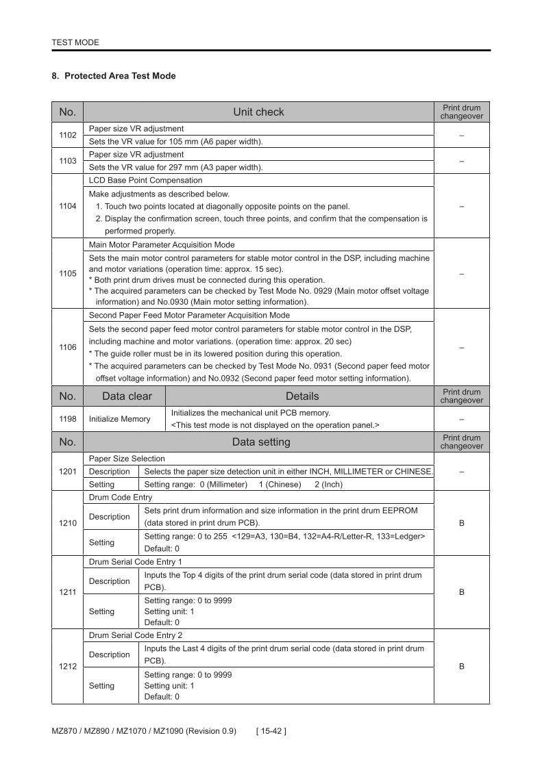
[ 15-42 ]MZ870 / MZ890 / MZ1070 / MZ1090 (Revision 0.9)
TEST MODE
No. Unit check Print drum changeover
1102Paper size VR adjustment
–Sets the VR value for 105 mm (A6 paper width).
1103Paper size VR adjustment
–Sets the VR value for 297 mm (A3 paper width).
1104
LCD Base Point Compensation
–Make adjustments as described below. 1. Touch two points located at diagonally opposite points on the panel. 2. Display the confirmation screen, touch three points, and confirm that the compensation is performed properly.
1105
Main Motor Parameter Acquisition Mode
–
Sets the main motor control parameters for stable motor control in the DSP, including machine and motor variations (operation time: approx. 15 sec). * Both print drum drives must be connected during this operation.* The acquired parameters can be checked by Test Mode No. 0929 (Main motor offset voltage information) and No.0930 (Main motor setting information).
1106
Second Paper Feed Motor Parameter Acquisition Mode
–
Sets the second paper feed motor control parameters for stable motor control in the DSP, including machine and motor variations. (operation time: approx. 20 sec) * The guide roller must be in its lowered position during this operation.* The acquired parameters can be checked by Test Mode No. 0931 (Second paper feed motor offset voltage information) and No.0932 (Second paper feed motor setting information).
No. Data clear Details Print drum changeover
1198 Initialize MemoryInitializes the mechanical unit PCB memory.<This test mode is not displayed on the operation panel.>
–
No. Data setting Print drum changeover
1201Paper Size Selection
–Description Selects the paper size detection unit in either INCH, MILLIMETER or CHINESE.Setting Setting range: 0 (Millimeter) 1 (Chinese) 2 (Inch)
1210
Drum Code Entry
BDescription
Sets print drum information and size information in the print drum EEPROM (data stored in print drum PCB).
SettingSetting range: 0 to 255 <129=A3, 130=B4, 132=A4-R/Letter-R, 133=Ledger> Default: 0
1211
Drum Serial Code Entry 1
BDescription
Inputs the Top 4 digits of the print drum serial code (data stored in print drum PCB).
SettingSetting range: 0 to 9999 Setting unit: 1 Default: 0
1212
Drum Serial Code Entry 2
BDescription
Inputs the Last 4 digits of the print drum serial code (data stored in print drum PCB).
SettingSetting range: 0 to 9999 Setting unit: 1 Default: 0
8. Protected Area Test Mode

[ 15-43 ] MZ870 / MZ890 / MZ1070 / MZ1090 (Revision 0.9)
TEST MODE
No. Data setting Print drum changeover
1214
Drum Color Code Entry
B
DescriptionSets the print drum color information in the print drum EEPROM (data stored in print drum PCB).
Setting
Setting range: 0 (Not specified) 2 (Blue) 4 (Red) 6 (Riso Federal Blue) 8 (Riso Marine Red) 10 (Green) 12 (Brown) 14 (Light Gray) 16 (Fluorescence Pink) 17 (Fluorescence Orange) 18 (Orange) 20 (Hunter Green) 30 (Custom color) 32 (Order: paper not specified)
1 (Black) 3 (Medium Blue) 5 (Bright Red) 7 (Purple) 9 (Burgundy) 11 (Teal) 13 (Yellow) 15 (Gray) 19 (Flat Gold) 21 (Crimson) 31 (Order: paper specified) 63 (Any color)
Default: 0 (Not specified)
1215
Drum Ink Category Entry
B
DescriptionSets the ink category code (3 bits) stored in the print drum EEPROM (data stored in print drum PCB). <This test mode is not displayed on the operation panel.>
SettingSetting range:
0 (Not specified) 1 (normal) 2 (HD) 3 N 4 (Spare 2) 5 (Spare 3) 6 (Spare 4) 7 (Spare 5)
Default: 0 (Not specified)
1220
Scanner Adjustment (1) Sub-Scanning Position Compensation
–Description Sets the value indicated on the sticker affixed to the scanner unit.
SettingSetting range: MZ8: 0 to 255 MZ10: 89 to167 Setting unit: 1 (0.0508mm) * (<+> for image to the top.) Default: 128
1221
Scanner Adjustment (2) Main-Scanning Position Compensation
–Description Sets the value indicated on the sticker affixed to the scanner unit.
SettingSetting range: MZ8: 0 to 255 MZ10: 81 to 175 Setting unit: 1 (0.0432mm = Approx. 24 dots) * (<+> for image to the left.) Default: 128
1222
Scanner Adjustment (3) Sub-Scanning Ratio Compensation
–Description Sets the value indicated on the sticker affixed to the scanner unit.
SettingSetting range: MZ8: 0 to 100 MZ10: 46 to 54 Setting unit: 1 (0.1%) * (<+> to shrink.) Default: 50

[ 15-44 ]MZ870 / MZ890 / MZ1070 / MZ1090 (Revision 0.9)
TEST MODE
No. Data setting Print drum changeover
1223
Scanner Adjustment (4) Offset
–
Description Sets the value indicated on the sticker affixed to the scanner unit.
Setting
Setting range: -255 to +255 Setting unit: 1 Default: 64 * The setting value varies automatically after offset adjustment, and the most recent setting value is used for the next offset adjustment. However, the value displayed in Test Mode does not change until the machine is restarted.
1224
Scanner Adjustment (5) Gain
–
Description Sets the value indicated on the sticker affixed to the scanner unit.
Setting
Setting range: 0 to 63Setting unit: 1 Default: 0 * The setting value varies automatically after gain adjustment, and the most recent setting value is used for the next gain adjustment. However, the value displayed in Test Mode does not change until the machine is restarted.
1229
Linked Printer (RLP) Enable Control
–Description Enables/disables linked printer function.
SettingSetting range: 0 (Disabled), 1 (Enabled) Default: 0 (Disabled)
1231
LCD Contrast Adjustment
–Description Adjusts panel contrast.
SettingSetting range: –120 to +120 Setting unit: 1 Default: 0
1232
LCD Backlight Adjustment
–Description Adjusts panel backlighting.
SettingSetting range: 50 to 115 Setting unit: 1 Default: 85
1233
TPH master-making horizontal position adjustment
B
Description Adjusts the horizontal print position of the thermal print head.
Setting
Setting range: –30 to +30 (–3.0 mm to +3.0 mm) Setting unit: 1 (0.1 mm) Default: 0 (0 mm)
* <+> moves the image to the back on the print drum (left on the prints).
1234
TPH resistance input
–
Description Sets thermal print head resistance.
Setting
Setting range: MZ8 (300x600 dpi) =1200 to 2300 (1200 ohm to 2300 ohm) MZ10 (600x600 dpi) = 1200 to 5920 (1200 ohm to 5920 ohm) Setting unit: 1 (1 ohm) Default: 1200 ohm

[ 15-45 ] MZ870 / MZ890 / MZ1070 / MZ1090 (Revision 0.9)
TEST MODE
No. Data setting Print drum changeover
1242
Scanning Adjustment (7) Offset-2
–
Description Sets the value indicated on the sticker affixed to the scanner unit.
Setting
Setting range: -255 to +255 Setting unit: 1 Default: 255* The setting value varies automatically after offset adjustment, and the most recent setting value is used for the next offset adjustment. However, the value displayed in Test Mode does not change until the machine is restarted.
1243
Scanning Adjustment (8) Gain-2
–
Description Sets the value indicated on the sticker affixed to the scanner unit.
Setting
Setting range: 0 to +64 Setting unit: 1 Default: 0* The setting value varies automatically after gain adjustment, and the most recent setting value is used for the next gain adjustment. However, the value displayed in Test Mode does not change until the machine is restarted.
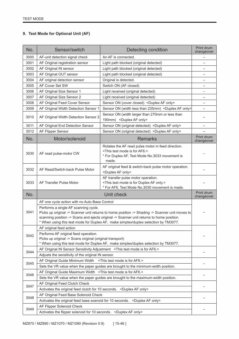
[ 15-46 ]MZ870 / MZ890 / MZ1070 / MZ1090 (Revision 0.9)
TEST MODE
No. Sensor/switch Detecting condition Print drum changeover
3000 AF-unit detection signal check An AF is connected. –3001 AF Original registration sensor Light path blocked (original detected) –3002 AF Original IN sensor Light path blocked (original detected) –3003 AF Original OUT sensor Light path blocked (original detected) –3004 AF original detection sensor Original is detected. –3005 AF Cover Set SW Switch ON (AF closed) –3006 AF Original Size Sensor 1 Light received (original detected) –3007 AF Original Size Sensor 2 Light received (original detected) –3008 AF Original Feed Cover Sensor Sensor ON (cover closed) <Duplex AF only> –3009 AF Original Width Detection Sensor 1 Sensor ON (width less than 235mm) <Duplex AF only> –
3010 AF Original Width Detection Sensor 2Sensor ON (width larger than 270mm or less than 190mm) <Duplex AF only>
–
3011 AF Original End Detection Sensor Sensor ON (original detected) <Duplex AF only> –3012 AF Flipper Sensor Sensor ON (original detected) <Duplex AF only> –
No. Motor/solenoid Remarks Print drum changeover
3030 AF read pulse-motor CW
Rotates the AF read pulse motor in feed direction.<This test mode is for AF6.>* For Duplex AF, Test Mode No.3033 movement is made.
–
3032 AF Read/Switch-back Pulse MotorAF original feed & switch-back pulse motor operation. <Duplex AF only>
–
3033 AF Transfer Pulse MotorAF transfer pulse motor operation.<This test mode is for Duplex AF only.>* For AF6, Test Mode No.3030 movement is made.
–
No. Unit check Print drum changeover
3041
AF one cycle action with no Auto Base Control
–Performs a single AF scanning cycle. Picks up original -> Scanner unit returns to home position -> Shading -> Scanner unit moves to scanning position -> Scans and ejects original -> Scanner unit returns to home position.* When using this test mode for Duplex AF, make simplex/duplex selection by TM3077.
3042
AF original feed action
–Performs AF original feed operation. Picks up original -> Scans original (original transport)* When using this test mode for Duplex AF, make simplex/duplex selection by TM3077.
3044AF Original IN Sensor Sensitivity Adjustment <This test mode is for AF6.>
–Adjusts the sensitivity of the original IN sensor.
3045AF Original Guide Minimum Width <This test mode is for AF6.>
–Sets the VR value when the paper guides are brought to the minimum-width position.
3046AF Original Guide Maximum Width <This test mode is for AF6.>
–Sets the VR value when the paper guides are brought to the maximum-width position.
3047AF Original Feed Clutch Check
–Activates the original feed clutch for 10 seconds. <Duplex AF only>
3048AF Original Feed Base Solenoid Check
–Activates the original feed base soenoid for 10 seconds. <Duplex AF only>
3049AF Flipper Solenoid Check
–Activates the flipper solenoid for 10 seconds. <Duplex AF only>
9. Test Mode for Optional Unit (AF)

[ 15-47 ] MZ870 / MZ890 / MZ1070 / MZ1090 (Revision 0.9)
TEST MODE
No. Data check Content of display Print drum changeover
3060 AF Original Width (A/D)Displays the A/D value of the AF original width. <This test mode is for AF6.>
–
3061 AF Original Size Code
AF6 Unit 00: No paper 01: A3 02: B4 03: A4 04: A4 Landscape 05: B5 06: B5 Landscape 07: A5 08: A5 Landscape 09: B611: Post Card (Japan size)13: Ledger 14: Legal 15: Letter 16: Letter Landscape 17; Statement 18: Statement Landscape 19: Foolscap 53: Custom Size
Duplex AF Unit 00: No paper 01: A3 02: B4 03: A4 04: A4 Landscape 05: B5 06: B5 Landscape 07: A5 08: A5 Landscape - - - - - - - - - - - -13: Ledger 14: Legal 15: Letter 16: Letter Landscape 17; Statement 18: Statement Landscape 19: Foolscap 53: Custom Size
–
No. Data setting Print drum changeover
3070
Scanner unit scanning position adjustment (AF scanning) <For both AF6 & Duplex scanner>
–Description Adjusts mirror (carriage) stop position in AF scanning operation.
Setting
Setting range: –20 to +20 (–2.0 mm to +2.0 mm) Setting unit: 1 (0.1 mm) Default: 0 (0 mm)
* <+> brings mirror carriage down = brings the printed image up.
3071
Mirror carriage position adjustment for Auto-Base-Control (AF scanning) <This test mode is for AF6.>
–Description Adjusts AF Auto-Base-Control mirror stop position.
Setting
Setting range: 0 to 30 (0 mm to 3.0 mm) Setting unit: 1 (0.1 mm) Default: 0 (0 mm)
* <+> brings mirror carriage down = brings the printed image up.
3072
Scanning horizontal position adjustment (AF scanning) <For both AF6 & Duplex scanner>
–Description
Adjusts horizontal position for scanning of original by the AF. (Separate test mode setting exist for the flatbed scanning.)
Setting
Setting range: –30 to +30 (–3.0 mm to +3.0 mm) Setting unit: 5 (0.5 mm) Default: 0 (0 mm)
* <+> for adjustment to the back of the print drum = to the left on the printout.
3073
Scanning start-position adjustment. (AF scanning)
–
DescriptionAdjusts original scanning start position (amount of scan skip) for the AF. <For both AF6 & Duplex scanner>
Setting
Setting range: –60 to +60 (–6.0 mm to +6.0 mm) Setting unit: 1 (0.1 mm) Default: 0 (0 mm)
* <+> brings the printed image up.

[ 15-48 ]MZ870 / MZ890 / MZ1070 / MZ1090 (Revision 0.9)
TEST MODE
No. Data setting Print drum changeover
3074
Scanning-speed adjustment to control Elongation & Shrinkage in scanning. <For both AF6 & Duplex scanner>
–
DescriptionAdjusts original scanning speed for the AF. (Adjusts AF read pulse motor speed.)
Setting
Setting range: AF6 Scanner: –50 to +50 (–5.0% to +5.0%). Duplex Scanner: –30 to +30 (–3.0% to +3.0%). Setting unit: 1 (0.1%) Default: 0 (0%)
* <+> to elongate
3076
AF Original END Signal Timing. <For both AF6 & Duplex scanner>
–
Description Adjusts original scanning end position.
Setting
Setting range: AF6 Scanner: –63 to +63 (–6.3 mm to +6.3 mm) Duplex Scanner: –30 to +30 (–3.0mm to +3.0mm). Setting unit: 1 (0.1 mm) Default: 0 (0 mm)
* <+> for scanning to continue further down.
3077
AF Original Feed Sequence Change <Duplex AF only>
–
Description AF original transfer action selection (1 cycle action).
Setting
Setting range: 0: Simplex 1: Duplex 2: Simplex (overside) for ejection to Sorter. Default: 0 (Simplex)
This test mode setting applies to Test Mode No. 3041 & 3042 operation.

[ 15-49 ] MZ870 / MZ890 / MZ1070 / MZ1090 (Revision 0.9)
TEST MODE
No. Sensor/switch Detecting condition Print drum changeover
3100 Job separator tape jam sensor ON when tape is jammed. –
3101 Job separator tape detection sensor ON where tape is detected. –
3102 Job separator power switch ON when powered ON –
3103 Job separator connection signal Job separator is connected. –
No. Unit check Print drum changeover
3140
Tape output
–Outputs one tape.* Test Mode No. 3170 Stamping Quantity is enabled
No. Data setting Print drum changeover
3170
Stamping quantity
–
DescriptionSets the number of stamping operations during Test Mode No. 3140 (Tape Output).
SettingSetting range:
0 (No stamping) 1 (1 stamping) 2 (2 stamping)* Returns back to the default setting when powered OFF.
Default: 0 (No stamping)
3171
Tape jammed message <activate or deactivate>
–
Description Displays/Hides the tape jam error display in tape output.
SettingSetting range:
0 (Disable) 1 (Enable)
Default: 1 (Enable)
10. Test Mode for Optional Unit (Job Separator)

[ 15-50 ]MZ870 / MZ890 / MZ1070 / MZ1090 (Revision 0.9)
TEST MODE
No. Unit check Print drum changeover
3340
Storage Memory Configuration Change
–Processing for changing the card used by the RP to a configuration compatible with the current machine. * Reconfigured card cannot be used by the RP. * Only one storage device should be set in the slot to permit configuration adjustments. (Two cards cannot be processed simultaneously.)
3341
Externally Connected Controller Status Printout
–With an external controller connected, the controller status page master is made and printed out.
No. Data clear Details Print drum changeover
3355 Storage Memory Initialize (32M)
Initializes the storage device to delete data from the 32M storage device or when an error related to storage device prevents data restoration. * Only one storage device can be set in the slot for initialization.
–
3356 Storage Memory Initialize (128M)
Initializes the storage device to delete data from the 128M storage device or when an error related to storage device prevents data restoration. * Only one storage device can be set in the slot for initialization.
–
3357 Storage Memory Initialize (FAT32)
Initializes the storage device to delete data from the 256M to 8GByte storage device or when an error related to storage device prevents data restoration. * Only one storage device can be set in the slot for initialization.
–
No. Data check Content of display Print drum changeover
3361 Storage Memory InformationDisplays the volume label, capacity, area used, and available storage volume. * Only one storage device can be set in the slot.
–
11. Test Mode for Optional Unit (Storage Memory)

[ 15-51 ] MZ870 / MZ890 / MZ1070 / MZ1090 (Revision 0.9)
TEST MODE
No. Data setting Print drum changeover
3570
RLP Print Position Adjustment (Main)
–Description
Adjusts RLP print position (main scanning direction = Horizontal adjustment). * If multiple RLP units are installed, this setting will affect all units.
SettingSetting range: –50 to +50 (–5.0 mm to +5.0 mm) Setting unit: 1 (0.1 mm) Default: 0 (0 mm)
* <+> moves to the left.
3571
RLP Print Position Adjustment (sub scanning direction = Vertical adjustment))
–Description
Adjusts RLP print position (sub scanning direction). * If multiple RLP units are installed, this setting will affect all units.
SettingSetting range: –50 to +50 (–5.0 mm to +5.0 mm) Setting unit: 1 (0.1 mm) Default: 0 (0 mm)
* <+> moves up
3572
Zero Print Master-making Warning
–
DescriptionWhen auto-link is turned ON and if master-making is performed with the print quantity set to 0 in PtoP mode (scan-to-print), this setting determines whether the warning (F60) is displayed or not.
Setting
Setting range:
0: (No warning message display.) 1: (Warning message is displayed.)
Default: 0: (No warning message display.)
3579
RLP Duplex Print Auto-Repeat
–
DescriptionSelection of whether the duplex printing selection is reset to simplex (OFF) or the duplex printing is automatically recalled for the next print job.
Setting
Setting range:
0: (OFF) 1: (Duplex setting is recalled)
Default: 1: (Duplex setting is recalled)
12. Test Mode for Optional Unit (Linked Printer)

[ 15-52 ]MZ870 / MZ890 / MZ1070 / MZ1090 (Revision 0.9)
TEST MODE
MEMO

[ 16-53 ] MZ870 / MZ890 / MZ1070 / MZ1090 (Revision 0.9)
PANEL MESSAGE
CHAPTER 16: PANEL MESSAGE
CONTENTS
Error Code Display .....................................................................................16-31. Error type .........................................................................................16-32. Error point ........................................................................................16-3
1) List of panel messages .........................................................................16-42) Details of error codes ............................................................................16-7
1. Service engineer call errors (T**) ....................................................16-72-1. Jam errors (A**) ...........................................................................16-252-2. Jam errors (A**: Indicates the detail of J-type error) ....................16-283. Option errors (B**) .........................................................................16-304. Consumable errors (C**) ...............................................................16-345. Set check errors (D**) ...................................................................16-366. Warning (E**: Service engineer call) .............................................16-437. Warning (F**: Others) ....................................................................16-448. Parameter Errors (H**) ..................................................................16-599. J-type Error Display (J**) ...............................................................16-6010. Errors Saved in Memory ................................................................16-60

[ 16-54 ]MZ870 / MZ890 / MZ1070 / MZ1090 (Revision 0.9)
PANEL MESSAGE
MEMO
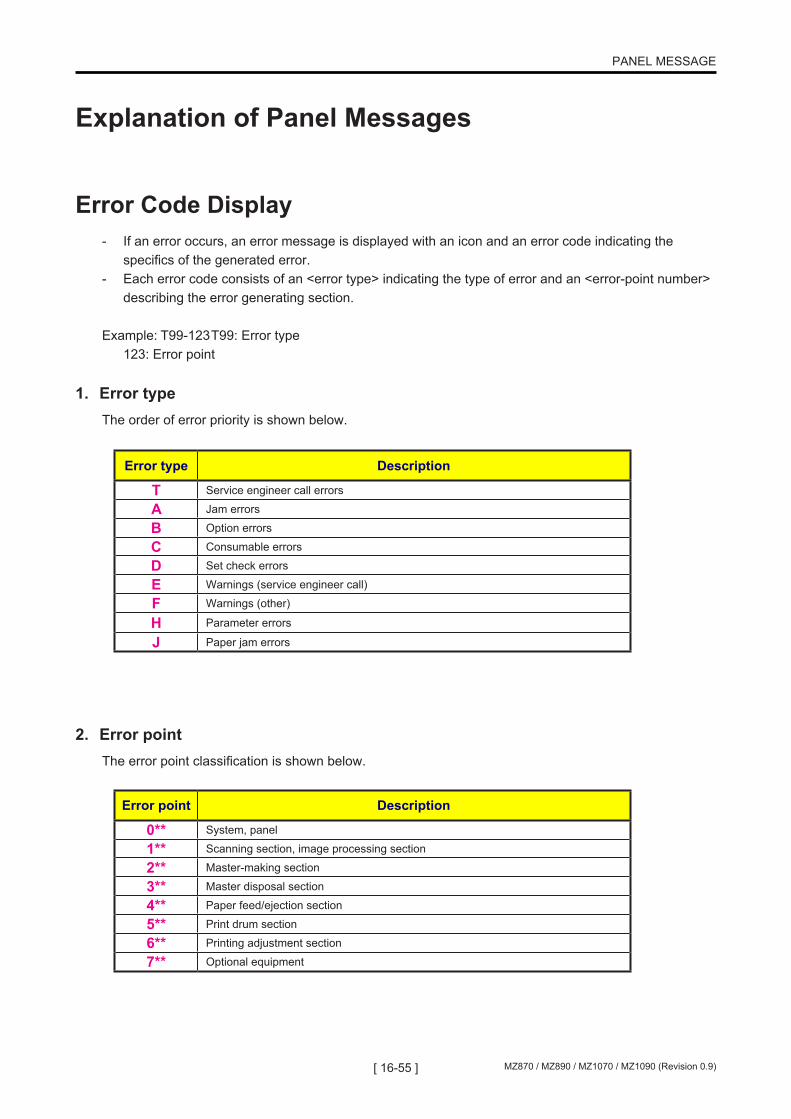
[ 16-55 ] MZ870 / MZ890 / MZ1070 / MZ1090 (Revision 0.9)
PANEL MESSAGE
Explanation of Panel Messages
Error Code Display- If an error occurs, an error message is displayed with an icon and an error code indicating the specifics of the generated error.- Each error code consists of an <error type> indicating the type of error and an <error-point number> describing the error generating section.
Example: T99-123 T99: Error type 123: Error point
1. Error typeThe order of error priority is shown below.
2. Error pointThe error point classification is shown below.
Error type Description
T Service engineer call errors
A Jam errors
B Option errors
C Consumable errors
D Set check errors
E Warnings (service engineer call)
F Warnings (other)
H Parameter errors
J Paper jam errors
Error point Description
0** System, panel
1** Scanning section, image processing section
2** Master-making section
3** Master disposal section
4** Paper feed/ejection section
5** Print drum section
6** Printing adjustment section
7** Optional equipment
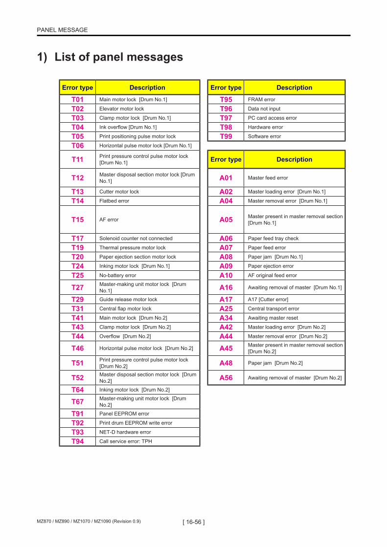
[ 16-56 ]MZ870 / MZ890 / MZ1070 / MZ1090 (Revision 0.9)
PANEL MESSAGE
1) List of panel messages
Error type Description Error type Description
T01 Main motor lock [Drum No.1] T95 FRAM error
T02 Elevator motor lock T96 Data not input
T03 Clamp motor lock [Drum No.1] T97 PC card access error
T04 Ink overflow [Drum No.1] T98 Hardware error
T05 Print positioning pulse motor lock T99 Software error
T06 Horizontal pulse motor lock [Drum No.1]
T11 Print pressure control pulse motor lock [Drum No.1] Error type Description
T12 Master disposal section motor lock [Drum No.1] A01 Master feed error
T13 Cutter motor lock A02 Master loading error [Drum No.1]
T14 Flatbed error A04 Master removal error [Drum No.1]
T15 AF error A05 Master present in master removal section [Drum No.1]
T17 Solenoid counter not connected A06 Paper feed tray check
T19 Thermal pressure motor lock A07 Paper feed error
T20 Paper ejection section motor lock A08 Paper jam [Drum No.1]
T24 Inking motor lock [Drum No.1] A09 Paper ejection error
T25 No-battery error A10 AF original feed error
T27 Master-making unit motor lock [Drum No.1] A16 Awaiting removal of master [Drum No.1]
T29 Guide release motor lock A17 A17 [Cutter error]
T31 Central flap motor lock A25 Central transport error
T41 Main motor lock [Drum No.2] A34 Awaiting master reset
T43 Clamp motor lock [Drum No.2] A42 Master loading error [Drum No.2]
T44 Overflow [Drum No.2] A44 Master removal error [Drum No.2]
T46 Horizontal pulse motor lock [Drum No.2] A45 Master present in master removal section [Drum No.2]
T51 Print pressure control pulse motor lock [Drum No.2] A48 Paper jam [Drum No.2]
T52 Master disposal section motor lock [Drum No.2] A56 Awaiting removal of master [Drum No.2]
T64 Inking motor lock [Drum No.2]
T67 Master-making unit motor lock [Drum No.2]
T91 Panel EEPROM error
T92 Print drum EEPROM write error
T93 NET-D hardware error
T94 Call service error: TPH
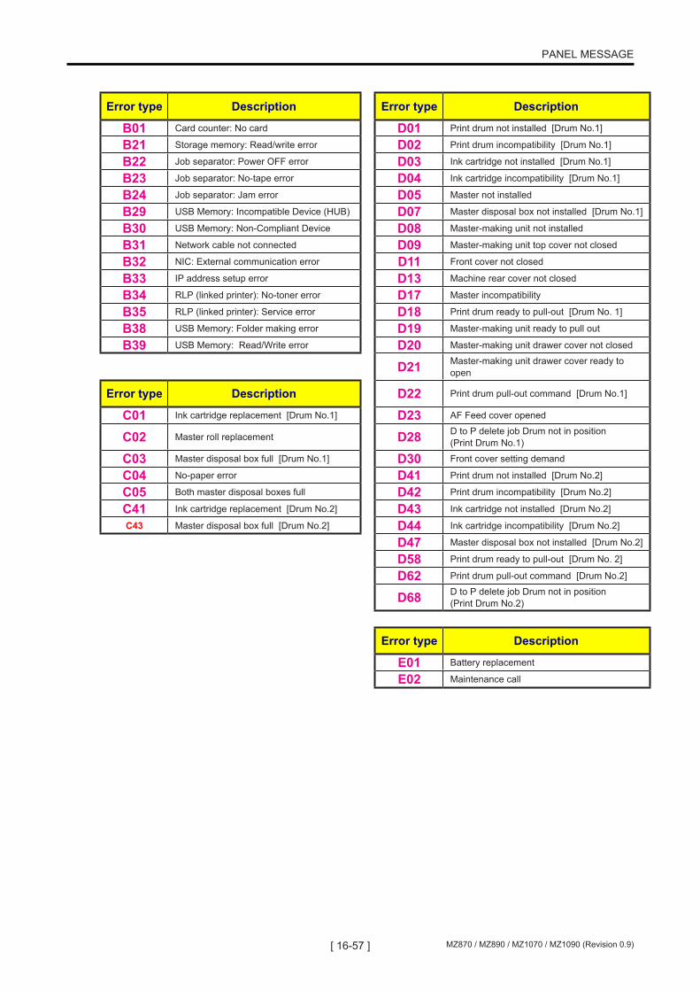
[ 16-57 ] MZ870 / MZ890 / MZ1070 / MZ1090 (Revision 0.9)
PANEL MESSAGE
Error type Description Error type Description
B01 Card counter: No card D01 Print drum not installed [Drum No.1]
B21 Storage memory: Read/write error D02 Print drum incompatibility [Drum No.1]
B22 Job separator: Power OFF error D03 Ink cartridge not installed [Drum No.1]
B23 Job separator: No-tape error D04 Ink cartridge incompatibility [Drum No.1]
B24 Job separator: Jam error D05 Master not installed
B29 USB Memory: Incompatible Device (HUB) D07 Master disposal box not installed [Drum No.1]
B30 USB Memory: Non-Compliant Device D08 Master-making unit not installed
B31 Network cable not connected D09 Master-making unit top cover not closed
B32 NIC: External communication error D11 Front cover not closed
B33 IP address setup error D13 Machine rear cover not closed
B34 RLP (linked printer): No-toner error D17 Master incompatibility
B35 RLP (linked printer): Service error D18 Print drum ready to pull-out [Drum No. 1]
B38 USB Memory: Folder making error D19 Master-making unit ready to pull out
B39 USB Memory: Read/Write error D20 Master-making unit drawer cover not closed
D21 Master-making unit drawer cover ready to open
Error type Description D22 Print drum pull-out command [Drum No.1]
C01 Ink cartridge replacement [Drum No.1] D23 AF Feed cover opened
C02 Master roll replacement D28 D to P delete job Drum not in position (Print Drum No.1)
C03 Master disposal box full [Drum No.1] D30 Front cover setting demand
C04 No-paper error D41 Print drum not installed [Drum No.2]
C05 Both master disposal boxes full D42 Print drum incompatibility [Drum No.2]
C41 Ink cartridge replacement [Drum No.2] D43 Ink cartridge not installed [Drum No.2]
C43 Master disposal box full [Drum No.2] D44 Ink cartridge incompatibility [Drum No.2]
D47 Master disposal box not installed [Drum No.2]
D58 Print drum ready to pull-out [Drum No. 2]
D62 Print drum pull-out command [Drum No.2]
D68 D to P delete job Drum not in position (Print Drum No.2)
Error type Description
E01 Battery replacement
E02 Maintenance call

[ 16-58 ]MZ870 / MZ890 / MZ1070 / MZ1090 (Revision 0.9)
PANEL MESSAGE
Error type Description Error type Description
F01 No master on Drum No.1 F67 RLP rotation sorting not possible
F02 Paper/master-making size incompatibility 1 F68 Specified area/traced color separation: Excess number of specified areas
F03 Multi-up: Paper size error F69Specified area/traced color separation: Distance of border for specified area longer than master-making size
F04 Admin. Setting: Maximum setting reached F70 Specified area/traced color separation: Image processing time-out error
F06 N-Up: Incorrect paper size F71 No master on Drum No.2
F07 N-Up: Incorrect original size F72 Hand-written/red-color separation: Image processing time-out error
F09 Booklet: Incorrect paper size F73 Auto tray selection not possible, RLP tray designation disabled
F10 Paper/master-making size incompatibility 2 F74 150ppm not possible due to low temperature
F11 Auto size reproduction disabled (falls outside range of possible size reproduction) F75 Combined use of specified area separation
and AF not possible
F13 4P Booklet was selected with wrong size paper on the paper feed tray] F76 Print drum color not matching with DtoP job
color [Drum No.2]
F14 4P Booklet was selected with wrong size original F77 Print drum color not matching with DtoP job
color [Drum No.1]
F20 Binding margin: Wrong paper size F78 Digitizer: Stage cover open
F24 Auto size reproduction disabled (falls outside range of possible size reproduction) F79 Digitizer: No original during re-scanning
F30 Multiple feed check F80 Paper not compatible with dual-color printing
F32 Storage memory: No space available F81 Dual-color printing: Ink-saving mode set on only one print drum
F33 USB memory: No space available F82 Paper not compatible for Drum No.2 printing
F37 Combined use of book mode and AF not possible F83 Use of Drum No.2 mode not possible
F43 DtoP original/paper incompatibility F85 Scanning not possible: External CI not connected
F44 Auto size reproduction disabled (exceeds original size detection range) F90 Supply stock management (ink)
F45 Presence of original unknown/no original F91 Supply stock management (master)
F46 Print drum color not matching with DtoP job color [Drum No. 1] F93 Reproduction ratio is larger than master
making area
F47 Combined use of AF and postcard size reproduction not possible F94 Protect confirmation (compulsory)
F48 Multi-up: Outside original size detection range F95 Protect confirmation
F49 Multi-up: No original when Start key pressed F96 Admin. Mode: Due Date for the ID Counter
Report
F52 Use of RLP mode not possible (RLP information not acquired) F97 Admin. Mode: Due Date for the Counter
Report
F58 Use of RLP mode not possible (NET-D initialization in process)
F60 RLP auto-link/master-making continuation confirmation (when printing quantity is 0) Error type Description
F61 RLP paper/original size incompatibility H01 Generic supply parameter input (Drum No.1)
F62 RLP auto-link/RLP error H04 Generic supply parameter input (master)
F63 RLP auto tray selection/nonstandard-size original H07 Generic supply parameter input (Drum No.2)
F64 Specified function disabled, at job reception
F65 Scan mode auto-saving size selection/non-standard size original
F66 RLP saddle stitching not possible

[ 16-59 ] MZ870 / MZ890 / MZ1070 / MZ1090 (Revision 0.9)
PANEL MESSAGE
2) Details of error codes1. Service engineer call errors (T**)
Error type T01 [Main motor lock] (Drum No.1)
Panel displayT01-*** !!System Error!! Press Reset Key If Recovery has Failed, Call Service
Error reset method Press the Reset key.
Error point Error detecting condition
520 Main motor lock [1] detected. The main motor FG sensor count reduced to 50% from the set speed.
521 The position B sensor does not change status within 2910 pulses while the main motor is ON.
523 Main motor lock [2] detected. (The main motor lock detected by DSP)
537 The print drum fails to stop at position B.
538 The print drum is not locked during operations.
Error type T02 [Elevator motor lock]
Panel displayT02-*** !!System Error!! Press Reset Key If Recovery has Failed, Call Service
Error reset method Press the Reset key or switch power OFF, then ON.
Error point Error detecting condition
400 The elevator upper-limit position detection and the elevator lower-limit detection are switches ON simultaneously.
401 Elevator motor overload detected. The elevator motor overcurrent port was activated 5 consecutive times (polling at 10-msec intervals).
404 The elevator lower-limit sensor does not switch OFF within 2 seconds after the elevator motor applies a lifting force from the elevator lower-limit position.
405 The elevator upper-limit sensor does not switch ON within 12 seconds after the elevator motor applies a lifting force.
406 The elevator upper-limit sensor does not switch OFF within 2 seconds after the elevator motor applies a lowering force from the elevator upper-limit position.
407 The elevator lower-limit sensor does not switch ON within 12 seconds after the elevator motor applies a lowering force.
408 The elevator upper-limit sensor remained OFF for more than 2 seconds during elevator servo action.

[ 16-60 ]MZ870 / MZ890 / MZ1070 / MZ1090 (Revision 0.9)
PANEL MESSAGE
Error type T03 [Clamp motor lock] (Drum No.1)
Panel displayT03-*** !!System Error!! Press Reset KeyIf Recovery has Failed, Call Service
Error reset method Press the Reset key.
Error point Error detecting condition
500 The clamp sensor A of the Clamp No.1 is OFF at the end of the clamp movement.
501 The clamp sensor B of the Clamp No.1 does not change status within 1 second after the clamp motor operates in the forward direction.
502 The clamp sensor B does not change status within 1 second after the clamp motor operates in the reverse direction.
503 The clamp sensor A of the Clamp No.1 does not switch ON within 3 seconds during clamp unit initialization.
504 The logical values of the clamp sensors A and B of the Clamp No.1 do not match at the start of the clamp releasing operation.
505 The logical values of the clamp sensors A and B of the Clamp No.1 do not match at the start of the print drum position-A compensation operation.
506 The logical values of the clamp sensors A and B of the Clamp No.1 do not match at the start of the clamp unit home positioning operation.
507 The clamp sensor A of the Clamp No.1 is ON after completion of the clamp releasing operation.
508 The clamp sensor A of the Clamp No.1 is ON after completion of the print drum position-A compensation operation.
514 The print drum is not at the horizontal home position while the clamp unit operates.
545 The clamp unit is not at the specified position at the start of print drum rotation.
546 The clamp unit is not at the home position at the start of print drum horizontal movement.
547 The clamp unit is not at the home position when the master-making unit slides.
Error type T04 [Ink overflow]
Panel displayT04-*** !!System Error!! Press Reset Key If Recovery has Failed, Call Service
Error reset method Press the Reset key with the overflow sensor switched OFF.
Error point Error detecting condition
513 The overflow sensor switches ON successively for the set number of times during the 10-ms-interval overflow sensor check.
Error type T05 [Print positioning pulse motor lock]
Panel displayT05-*** !!System Error!! Press Reset Key If Recovery has Failed, Call Service
Error reset method Press the Reset key or switch power OFF, then ON.
Error point Error detecting condition
603 The Vertical Print Positioning Pulse Motor did not complete the movement within the set time when the motor rotated in the print image downward direction.
604 The Vertical Print Positioning Pulse Motor did not complete the movement within the set time when the motor rotated in the print image upward direction.

[ 16-61 ] MZ870 / MZ890 / MZ1070 / MZ1090 (Revision 0.9)
PANEL MESSAGE
Error type T06 [Horizontal pulse motor lock] (Drum No.1)
Panel displayT06-*** !!System Error!! Press Reset Key If Recovery has Failed, Call Service
Error reset method Press the Reset key or switch power OFF, then ON.
Error point Error detecting condition
607 The horizontal home position sensor detects no light within the set period after the print drum drive releasing operation started.
608 Athe light path of he horizontal home position sensor is not blocked within the set time after the print drum connecting operation started.
609Although the horizontal pulse motor has completed the operation in sensor stop mode, the logical value of the sensor at the arrival point does not match the design value, or the operation fails to complete in counter stop mode within the specified time.
627 The light path of the drive release home position sensor is not blocked during print drum drive connecting operation.
628 The light path of the drive release home position sensor is not detected during print drum drive release operation.
Error type T11 [Print pressure control pulse motor lock] (Drum No.1)
Panel display
T11-*** !!System Error!! Press Reset Key If Recovery has Failed, Call Service
Error reset method Press the Reset key or switch power OFF, then ON.
Error point Error detecting condition
600 The print pressure control sensor does not change from OFF to ON within 3.9 seconds after the print pressure control motor activates to increase pressure during home positioning.
601 The print pressure control sensor does not change from ON to OFF within 4.6 seconds after the print pressure control motor activates to reduce pressure during home positioning.
602Although the print pressure control pulse motor has completed the operation in sensor stop mode, the logical value of the sensor at the arrival point does not match the design value, or the operation fails to complete in counter stop mode within the specified time.

[ 16-62 ]MZ870 / MZ890 / MZ1070 / MZ1090 (Revision 0.9)
PANEL MESSAGE
Error type T12 [Master disposal section motor lock] (Drum No.1)
Panel displayT12-*** !!System Error!! Press Reset Key If Recovery has Failed, Call Service
Error reset method Press the Reset key.
Error point Error detecting condition
300 Overload current detected in master disposal motor. The master disposal motor over current was detected 5 consecutive times (polling at 10-msec intervals).
301 Master compression motor lock detected. The compression detection switch went ON while lifting the compression plate.
302 The compression FG value was larger than normal when the compression plate made HP movement preparation.
305 The master compression HP sensor does not switch ON within 7.5 seconds after the master compression motor activates to lift the compression plate.
306 The master compression HP sensor does not switch OFF within 2 seconds after the master compression motor activates in the compressing direction.
307
[1] The compression detection does not switch ON within 7.5 seconds after the master compression motor activates in the compressing direction. (Within 5 seconds if moving to the Protect position.). [2] The master compression FG sesnor does not count 20 pulses even after the master compression motor rotated in the compressing direction for 800ms.
309The FG count value does not change when the master compression motor applies a force to begin the compression, after moving away from the home position sensor. (The master compression motor FG sensor status does not change.)
316 Master disposal motor lock detected. The master disposal motor FG count reduced to half the value from the set speed.
Error type T13 [Cutter motor lock]
Panel displayT13-*** !!System Error!! Press Reset Key If Recovery has Failed, Call Service
Error reset method Press the Reset key.
Error point Error detecting condition
203 The cutter home position switch does not change from ON to OFF within 100 ms after the cutter unit moves from the home position.
204 The cutter home position switch does not switch ON within 300 ms after the cutter begins operating.
205 The master positioning sensor is ON even when the print drum rotates to the specified angle after cutting the master.
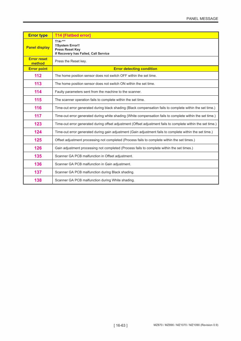
[ 16-63 ] MZ870 / MZ890 / MZ1070 / MZ1090 (Revision 0.9)
PANEL MESSAGE
Error type T14 [Flatbed error]
Panel displayT14-*** !!System Error!! Press Reset Key If Recovery has Failed, Call Service
Error reset method Press the Reset key.
Error point Error detecting condition
112 The home position sensor does not switch OFF within the set time.
113 The home position sensor does not switch ON within the set time.
114 Faulty parameters sent from the machine to the scanner.
115 The scanner operation fails to complete within the set time.
116 Time-out error generated during black shading (Black compensation fails to complete within the set time.)
117 Time-out error generated during white shading (White compensation fails to complete within the set time.)
123 Time-out error generated during offset adjustment (Offset adjustment fails to complete within the set time.)
124 Time-out error generated during gain adjustment (Gain adjustment fails to complete within the set time.)
125 Offset adjustment processing not completed (Process fails to complete within the set times.)
126 Gain adjustment processing not completed (Process fails to complete within the set times.)
135 Scanner GA PCB malfunction in Offset adjustment.
136 Scanner GA PCB malfunction in Gain adjustment.
137 Scanner GA PCB malfunction during Black shading.
138 Scanner GA PCB malfunction during White shading.

[ 16-64 ]MZ870 / MZ890 / MZ1070 / MZ1090 (Revision 0.9)
PANEL MESSAGE
Error type T15 [AF error]
Panel displayT15-*** !!System Error!! Turn Main Power SW OFF Then ON If Recovery has Failed, Call Service
Error reset method Switch power OFF, then ON.
Error point Error detecting condition
100 Original IN sensor adjustment error in the AF.
101 AF-EEPROM error.
110Time-out error generated at the ABC standby position. This error is issued if the original stops at the ABC standby position after the start of AF scanning operation (with ABC), and the original remains electrically charged for the set time. * Error issued from AF.
130AF command reception time-out error generated in the main printer unit. After a command is sent from the printer to the AF, if no response is transmitted within the set time, the same command is retransmitted. This error is generated if no response is made to this retransmitted command within the set time.
131 The main printer unit received an undefined command from the AF.
132 The main printer unit detected a communication sequence error in the AF unit. * Error issued from AF.
133 AF communication error in the main printer unit (ACK or NAK error).
134The main printer unit did not transmit a signal to the AF within the set time. After a command is sent from the AF to the printer, if no response is transmitted within the set time, the same command is retransmitted. This error is generated if no response is made to this retransmitted command within the set time.
143 Original width VR value error in the AF.
161 AF unit not connected.
Error type T17 [Solenoid counter not connected]
Panel displayT17-*** !!System Error!! Press Reset Key If Recovery has Failed, Call Service
Error reset method Solenoid counter connection signal: ON
Error point Error detecting condition
020 The solenoid counter is not connected.

[ 16-65 ] MZ870 / MZ890 / MZ1070 / MZ1090 (Revision 0.9)
PANEL MESSAGE
Error type T19 [Thermal pressure motor lock]
Panel displayT19-*** !!System Error!! Press Reset Key If Recovery has Failed, Call Service
Error reset method Press the Reset key.
Error point Error detecting condition
207 The TPH pressure sensor does not change from ON to OFF within 2 seconds after the thermal pressure motor operates to reduce pressure (or during home positioning).
208 The TPH pressure sensor does not change from OFF to ON within 2 seconds after the thermal pressure motor operates to reduce pressure.
216 The TPH pressure sensor does not change from ON to OFF within 2 seconds after the thermal pressure motor operates to apply pressure.
217 The TPH pressure sensor does not change from OFF to ON within 2 seconds after the thermal pressure motor operates to apply pressure.
Error type T20 [Paper ejection section motor lock]
Panel displayT20-*** !!System Error!! Press Reset Key If Recovery has Failed, Call Service
Error reset method Press the Reset key.
Error point Error detecting condition
414 The paper ejection wing home position sensor does not change status within the set time after the paper ejection wing pulse motor starts operation.
415The paper ejection wing home position sensor does not switch OFF within the set time after the paper ejection wing pulse motor operates when the paper ejection wings are at the home position (home position sensor ON).
416Paper ejection motor overload current detected. The motor over-current port switches ON 2 consecutive times after the paper ejection motor switches ON (polling at 10-msec intervals).
437 Paper ejection motor lock detected. The paper ejection motor FG sensor count reduced to half from the set count.
442Although the paper ejection wing pulse motor has completed the operation in sensor stop mode, the logical value of the sensor at the arrival point does not match the design value, or the operation fails to complete in counter stop mode within the specified time.
Error type T24 [Inking motor lock] (Drum No.1)
Panel displayT24-*** !!System Error!! Press Reset Key If Recovery has Failed, Call Service
Error reset method Press the Reset key or switch power OFF, then ON.
Error point Error detecting condition
539Inking motor lock detected. The inking motor FG sensor status did not change even after 200msec from the operation of the inking motor.

[ 16-66 ]MZ870 / MZ890 / MZ1070 / MZ1090 (Revision 0.9)
PANEL MESSAGE
Error type T25 [No-battery error]
Panel displayT25-*** !!Low Battery!! Call Service
Error reset method Replace the battery.
Error point Error detecting condition
026 No battery power. * Readjust the machine clock after resetting the error.
Error type T27 [Master-making unit motor lock] (Drum No.1)
Panel displayT27-*** !!System Error!! Press Reset Key If Recovery has Failed, Call Service
Error reset method Press the Reset key.
Error point Error detecting condition
248 The master-making unit position sensor does not change status as specified within the set time after the master-making unit begins moving to the standby position.
249 The light path of the master-making unit pull-out position sensor was not blocked within the set time when the master-making unit moved to the pull-out position.
250 The master-making unit position sensor does not change status as specified within the set time after the master-making unit begins moving to the master-making position.
251Although the master-making unit transport pulse motor has completed the operation in sensor stop mode, the logical value of the sensor at the arrival point does not match the design value. Or the operation fails to complete in counter stop mode within the specified time.
252 The top cover of the master-making unit opened at a location other than the master-making unit pull-out position. (The pressure plate opened when the master-making-unit was moving.)
257 The top cover of the master-making unit opened at a location other than the master-making unit pull-out position. (The master-making-unit tried to move with its top cover opened.)
Error type T29 [Guide release motor lock]
Panel displayT29-*** !!System Error!! Press Reset Key If Recovery has Failed, Call Service
Error reset method Press the Reset key.
Error point Error detecting condition
438 The guide roller release home position sensor detects no light within 3.8 seconds after the guide roller begins operating.
439 The light path of the guide roller release home position sensor is not blocked within 3.8 seconds after the guide roller begins operating.
450Overload current detected in the guide roller release motor. The guide roller release motor overcurrent port switches ON 20 consecutive times (polling at 10-msec intervals).

[ 16-67 ] MZ870 / MZ890 / MZ1070 / MZ1090 (Revision 0.9)
PANEL MESSAGE
Error type T31 [Central flap motor lock]
Panel displayT31-*** !!System Error!! Press Reset Key If Recovery has Failed, Call Service
Error reset method Press the Reset key.
Error point Error detecting condition
445 The central flap home position sensor detects no light within the set time after the central flap motor begins operating.
446 The light path of the central flap home position sensor is not blocked within the set time after the central flap motor begins operating.
451 Overload current detected in the central flap motor. The central flap motor overcurrent port switches ON 20 consecutive times (polling at 10-msec intervals).
Error type T41 [Main motor lock] (Drum No.2)
Panel displayT41-*** !!System Error!! Press Reset Key If Recovery has Failed, Call Service
Error reset method Press the Reset key.
Error point Error detecting condition521 The position-B sensor does not change status within 2910 pulses while the main motor is ON.
523 Main motor lock [2] detected by DPS.
537 The position-B stop operation failed.
538 The print drum is not locked during print drum operation.
Error type T43 [Clamp motor lock] (Drum No.2)
Panel displayT43-*** !!System Error!! Press Reset Key If Recovery has Failed, Call Service
Error reset method Press the Reset key.
Error point Error detecting condition500 The Second clamp sensor logical value is incorrect when the Second clamp completes the movement.
501 The Second clamp sensor does not change status within 1 second after the clamp motor begins rotating in the forward direction.
502 The Second clamp sensor does not change status within 1 second after the clamp motor begins rotating in the reverse direction.
504 The logical values of the Second clamp sensor is incorrect at the start of the clamp releasing operation.
506 The logical values of the Second clamp sensor is incorrect at the start of the clamp unit home positioning operation.
514 The print drum is not at the horizontal home position while the clamp unit is operating.
545 The clamp unit is not at the specified position when the print drum begins rotating.
546 The clamp unit is not at the home position when the print drum initiates horizontal movement.
547 The clamp unit is not at the home position when the master-making unit begins its motion.
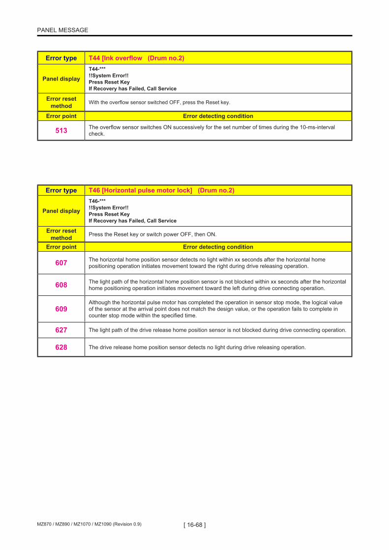
[ 16-68 ]MZ870 / MZ890 / MZ1070 / MZ1090 (Revision 0.9)
PANEL MESSAGE
Error type T44 [Ink overflow (Drum no.2)
Panel displayT44-*** !!System Error!! Press Reset Key If Recovery has Failed, Call Service
Error reset method With the overflow sensor switched OFF, press the Reset key.
Error point Error detecting condition
513 The overflow sensor switches ON successively for the set number of times during the 10-ms-interval check.
Error type T46 [Horizontal pulse motor lock] (Drum no.2)
Panel displayT46-*** !!System Error!! Press Reset Key If Recovery has Failed, Call Service
Error reset method Press the Reset key or switch power OFF, then ON.
Error point Error detecting condition
607 The horizontal home position sensor detects no light within xx seconds after the horizontal home positioning operation initiates movement toward the right during drive releasing operation.
608 The light path of the horizontal home position sensor is not blocked within xx seconds after the horizontal home positioning operation initiates movement toward the left during drive connecting operation.
609Although the horizontal pulse motor has completed the operation in sensor stop mode, the logical value of the sensor at the arrival point does not match the design value, or the operation fails to complete in counter stop mode within the specified time.
627 The light path of the drive release home position sensor is not blocked during drive connecting operation.
628 The drive release home position sensor detects no light during drive releasing operation.

[ 16-69 ] MZ870 / MZ890 / MZ1070 / MZ1090 (Revision 0.9)
PANEL MESSAGE
Error type T51 [Print pressure control pulse motor lock] (Drum No.2)
Panel displayT51-*** !!System Error!! Press Reset Key If Recovery has Failed, Call Service
Error reset method Press the Reset key or switch power OFF, then ON.
Error point Error detecting condition
600The print pressure control sensor does not change from OFF to ON within 3.9 seconds after the print pressure control pulse motor activates to increase pressure during home positioning.
601The print pressure control sensor does not change from ON to OFF within 4.6 seconds after the print pressure control pulse motor activates to reduce pressure during home positioning.
602Although the print pressure control pulse motor has completed the operation in sensor stop mode, the logical value of the sensor at the arrival point does not match the design value, or the operation fails to complete in counter stop mode within the specified time.
Error type T52 [Master disposal section motor lock] (Drum No.2)
Panel displayT52-*** !!System Error!! Press Reset Key If Recovery has Failed, Call Service
Error reset method Press the Reset key.
Error point Error detecting condition
300Overload current detected in master disposal motor. The master disposal motor over current was detected 5 times consecutively (polling at 10-msec intervals).
301 Master compression motor lock detected. The compression detection switch went ON while lifting the compression plate.
305 The master compression HP sensor does not switch ON within 7.5 seconds after the master compression motor activates to lift the compression plate.
306 The master compression HP sensor does not switch OFF within 2 seconds after the master compression motor activates in the compressing direction.
307
[1] The compression detection does not switch ON within 7.5 seconds after the master compression motor activates in the compressing direction. (Within 5 seconds if moving to the Protect position.). [2] The master compression FG sesnor does not count 20 pulses even after the master compression motor rotated in the compressing direction for 800ms.
309The FG count value does not change when the master compression motor applies a force to begin the compression, after moving away from the home position sensor. (The master compression motor FG sensor status does not change.)
316 Master disposal motor lock detected. The master disposal motor FG count reduced to half the value from the set speed.
Error type T64 [Inking motor lock] (Drum No.2)
Panel displayT64-*** !!System Error!! Press Reset Key If Recovery has Failed, Call Service
Error reset method Press the Reset key or switch power OFF, then ON.
Error point Error detecting condition
539Inking motor lock detected. The inking motor FG sensor does not change status within 20 ms after the inking motor switches ON.

[ 16-70 ]MZ870 / MZ890 / MZ1070 / MZ1090 (Revision 0.9)
PANEL MESSAGE
Error type T67 [Master-making unit motor lock] (Drum No.2)
Panel displayT67-*** !!System Error!! Press Reset Key If Recovery has Failed, Call Service
Error reset method Press the Reset key.
Error point Error detecting condition
248 The master-making unit position sensor does not change status as specified within the set time after the master-making unit begins moving to the standby position.
250 The master-making unit position sensor does not change status as specified within the set time after the master-making unit begins moving to the master-making position.

[ 16-71 ] MZ870 / MZ890 / MZ1070 / MZ1090 (Revision 0.9)
PANEL MESSAGE
Error type T91 [Panel EEPROM error]
Panel displayT91-*** !!System Error!! Press Reset Key If Recovery has Failed, Call Service
Error reset method Press the Reset key.
Error point Error detecting condition
013 The date information data is incorrect
968 Read error generated in the panel EEPROM.
969 Write error generated in the panel EEPROM.
976 Checksum error generated in the panel EEPROM.
977 Verification error generated in the panel EEPROM.
Error type T92 [Print drum EEPROM write error]
Panel displayT92-*** !!System Error!! Press Reset Key If Recovery has Failed, Call Service
Error reset method Press the Reset key.
Error point Error detecting condition
570 The print drum EEPROM is being accessed while the print drum is performing a releasing action.
Error type T93 [NET-D hardware error]
Panel displayT93-*** !!System Error!! Turn Main Power SW OFF Then ON If Recovery has Failed, Call Service
Error reset method Switch power OFF, then ON.
Error point Error detecting condition
932 No response from the NIC (Network Interface Card) when NIC is accessed.
Error type T94 [Call service error: TPH]
Panel displayT94-*** !!System Error!! Turn Main Power SW OFF Then ON If Recovery has Failed, Call Service
Error reset method Switch power OFF, then ON.
Error point Error detecting condition
225The TPH code does not correspond to the machine model code when the power is switched ON (only when the master-making unit is in the operating position) or when the master-making unit is inserted in the operating position.

[ 16-72 ]MZ870 / MZ890 / MZ1070 / MZ1090 (Revision 0.9)
PANEL MESSAGE
Error type T95 [FRAM error]
Panel displayT95-*** !!System Error!! Turn Main Power SW OFF Then ON If Recovery has Failed, Call Service
Error reset method Switch power OFF, then ON.
Error point Error detecting condition
059 The machine serial number information sent from the SH-PCB does not correspond to the machine serial number information in the mechanical control PCB.
Error type T96 [Data not input]
Panel displayT96-*** !!System Error!! Turn Main Power SW OFF Then ON If Recovery has Failed, Call Service
Error reset method Enter parameters in Test Mode.
Error point Error detecting condition
171 TPH resistance not set.
172 Scanner adjustment not completed.
433 Paper width potentiometer (VR) not set.
569 Print drum color or ink category not set.
613 Print pressure compensation not set.
972 REv data storage area not initialized.
Error type T97 [PC card access error]
Panel displayT97-*** !!System Error!! Press Reset Key If Recovery has Failed, Call Service
Error reset method Press the Reset key.
Error point Error detecting condition939 PC card access error: PC card not set.
940 PC card access error: Device information multiple-ID error (PCMCIA card information error).
941 PC card access error: Device error (incompatible CF card error).
942 PC card access error: File creation failed (File with the same name already exists).
943 PC card access error: Unformatted.
944 PC card access error: Media ID error.
945 PC card access error: Media error (CF card cannot be accessed).
946 PC card access error: Insufficient disc capacity (Not enough space available on the CF card to write data).
990 PC card access error: Specified file not found on the selected drive.
991 PC card access error: The file accessed is not currently open.
992 PC card access error: File information storage folder already in use.
993 PC card access error: Incorrect read address setting for data transfer to mechanical unit.
994 PC card access error: File deletion failed.

[ 16-73 ] MZ870 / MZ890 / MZ1070 / MZ1090 (Revision 0.9)
PANEL MESSAGE
Error type T98 [Hardware error]
Panel displayT98-*** !!System Error!! Turn Main Power SW OFF Then ON If Recovery has Failed, Call Service
Error reset method Switch power OFF, then ON.
Error point Error detecting condition005 Hardware error (Machine model code error).
006 FRAM checksum error.
025 Faulty tag RF PCB on the print durm (initial communication with the tag RF PCB failed).
028 Test Mode NO. 103 [Machine Test-Mode Data Recording] failed.
029 Test Mode NO. 105 [Machine Test-Mode Data Re-store] failed.
034 Unable to write data to the main unit EEPROM (EEPROM cannot be accessed).
035 CRC <cyclic redundancy check> error generated in the main unit EEPROM (EEPROM data error).
039 Incorrect EEPROM.
051 Communication error with touch-panel controller.
053 Unsuccessful attempt to read memory parameters (program, mode, user paper).
054 Unsuccessful attempt to write memory parameters (program, mode, user paper).
055 The machine model code sent from the SH-PCB does not correspond to the machine model information in the mechanical control PCB.
063The test mode parameter setting data in the memory is out of selectable range. CAUTION: When this error displays, make sure to go into Test Mode and activate Test Mode No.112 [Clearing Normal Area Test Mode Dara Memory], or the machine mechanical mechanism may damage.
064 Communication between SH PCB and mechanical control PCB: Undefined command was issued.
065 Communication error between SH PCB and mechanical control PCB (01) (on mechanical control PCB side): Incorrect number of bytes exist in received command.
067 Communication error between SH PCB and mechanical control PCB (03) (on mechanical control PCB side): RNK received.
068 Communication error between SH PCB and mechanical control PCB (04) (on mechanical control PCB side): NAK received 3 times.
069 Communication error between SH PCB and mechanical control PCB (05) (on mechanical control PCB side): No ACK response.
070 Communication error between SH PCB and mechanical control PCB (06) (on mechanical control PCB side): Transmission prevented by SH PCB.
071 Communication error between SH PCB and mechanical control PCB (07) (on mechanical control PCB side): Command received while awaiting response.
072 Communication error between SH PCB and mechanical control PCB (08) (on mechanical control PCB side): FB command received in mode other than download mode.
073 Communication error between SH PCB and mechanical control PCB (09) (on mechanical control PCB side): FC/FD command received in mode other than download mode.
074 Communication error between SH PCB and mechanical control PCB (10) (on SH PCB side): FE command received (No mechanical control PCB program).
075 Communication error between SH PCB and mechanical control PCB (11) (on SH PCB side): Incorrect number of bytes in received command.
076 Communication error between SH PCB and mechanical control PCB (12) (on SH PCB side): Received ACK not specified in sequence.
077 Communication error between SH PCB and mechanical control PCB (13) (on SH PCB side): RNK received.
078 Communication error between SH PCB and mechanical control PCB (14) (on SH PCB side): NAK received 3 times.
079 Communication error between SH PCB and mechanical control PCB (15) (on SH PCB side): No ACK response.
080 Communication error between SH PCB and mechanical control PCB (16) (on SH PCB side): Transmission prevented by the mechanical control PCB (CTS = 1).

[ 16-74 ]MZ870 / MZ890 / MZ1070 / MZ1090 (Revision 0.9)
PANEL MESSAGE
Error type T98 [Hardware error]
Panel displayT98-*** !!System Error!! Turn Main Power SW OFF Then ON If Recovery has Failed, Call Service
Error reset method Switch power OFF, then ON.
Error point Error detecting condition
081 Communication error between SH PCB and mechanical control PCB (17) (on SH PCB side): Mechanical control download mode was transmitted by error.
082 Communication error between SH PCB and mechanical control PCB (18) (on SH PCB side): Mechanical CTS remained at <1> for 2 seconds.
083 Communication error between SH PCB and mechanical control PCB (19) (on SH PCB side): FA command received at time other than startup.
084 Communication error between SH PCB and mechanical control PCB (20) (on SH PCB side): <80> command not received within 10 seconds after power ON.
094 Communication sequence error between SH PCB and mechanical control PCB. (Mechanical control PCB error).
097 The Test Mode adjustment value set in the print drum memory lies outside the adjustment range.
098 The machine serial number information in the main unit EEPROM does not correspond to the machine serial number information in the FRAM.
099 SH4F PCB: Undefined interrupt processing was generated.
119 Faulty image PCB (Memory check of the image processing IC failed). (Image processing IC check timing: during initialization)
120
Time-out error generated while awaiting scanner serial communication interrupt command (The CPU failed to receive interrupt command from FORCE device within 100 ms).
Scanner serial communication timing:
Transmission of data to AK8412 (A/D converter). Transmission of data to scanner gate array. Reading of data from scanner gate array. Reading of TPH thermister A/D converter data.
129 Faulty scanner gate array PCB (Error generated in the memory check of the scanner gate array).
245 Time-out error (action other than sensor standard) for the write pulse motor during master transport in master-making operation.
246 Time-out error (action other than sensor standard) for the load pulse motor during master transport in master-making operation.
422The DA setting for adjustment of the light-emitting section reached the upper-limit value during automatic multiple paper feed adjustment in Test Mode No. 705 [Multiple Paper Feed Detection Sensor Sensitivity Automatic Adjustment].
423The DA setting for adjustment of the light-emitting section reached the lower-limit value during automatic multiple paper feed sensor adjustment in Test Mode No. 705 [Multiple Paper Feed Detection Sensor Sensitivity Automatic Adjustment].
448The DA setting for adjustment of the light-emitting section reached the upper-limit value during automatic registration sensor adjustment in Test Mode No. 709 [Registration Sensor Sensitivity Automatic Adjustment].
449The DA setting for adjustment of the light-emitting section reached the lower-limit value during automatic registration sensor adjustment in Test Mode No. 709 [Registration Sensor Sensitivity Automatic Adjustment].
453 Timeout during multiple feed sensor sensitivity automatic adjustment. (Error displays when the adjustment is made without paper.)
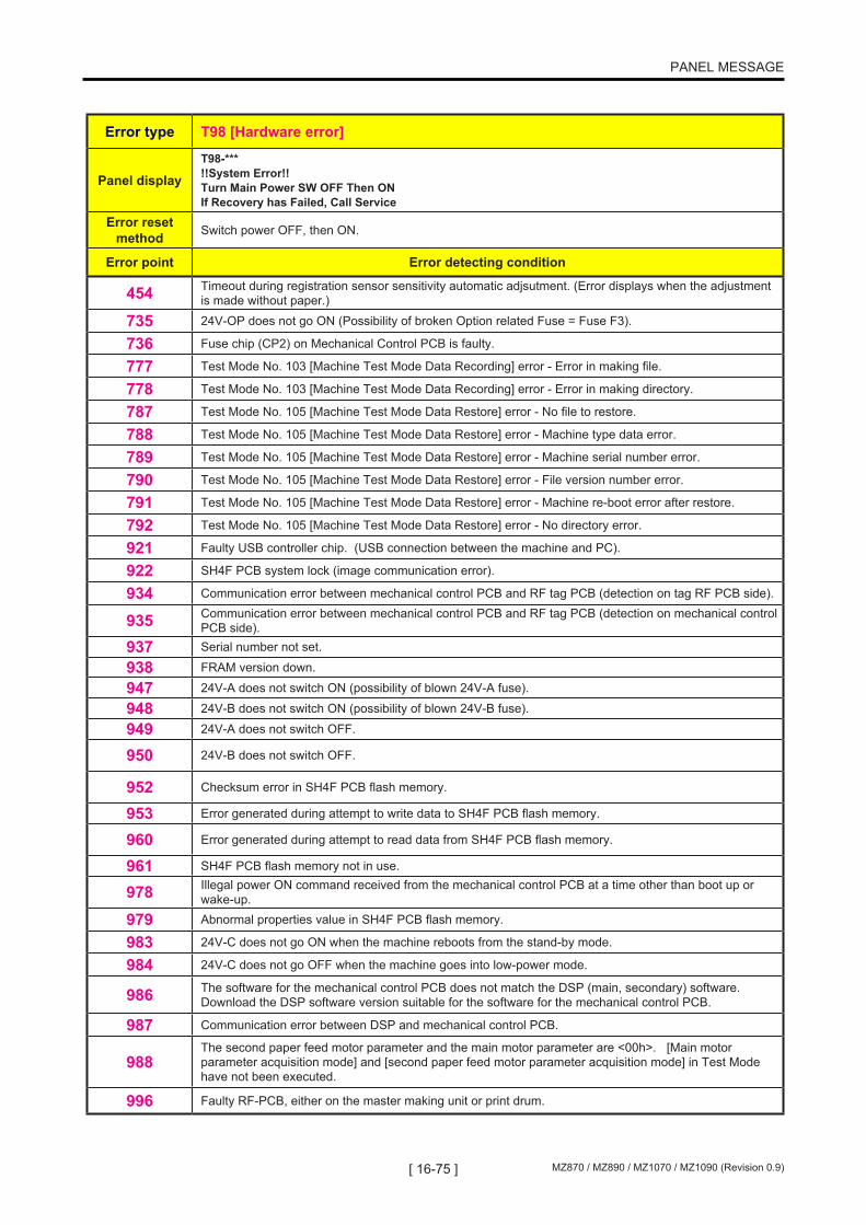
[ 16-75 ] MZ870 / MZ890 / MZ1070 / MZ1090 (Revision 0.9)
PANEL MESSAGE
Error type T98 [Hardware error]
Panel displayT98-*** !!System Error!! Turn Main Power SW OFF Then ON If Recovery has Failed, Call Service
Error reset method Switch power OFF, then ON.
Error point Error detecting condition
454 Timeout during registration sensor sensitivity automatic adjsutment. (Error displays when the adjustment is made without paper.)
735 24V-OP does not go ON (Possibility of broken Option related Fuse = Fuse F3).
736 Fuse chip (CP2) on Mechanical Control PCB is faulty.
777 Test Mode No. 103 [Machine Test Mode Data Recording] error - Error in making file.
778 Test Mode No. 103 [Machine Test Mode Data Recording] error - Error in making directory.
787 Test Mode No. 105 [Machine Test Mode Data Restore] error - No file to restore.
788 Test Mode No. 105 [Machine Test Mode Data Restore] error - Machine type data error.
789 Test Mode No. 105 [Machine Test Mode Data Restore] error - Machine serial number error.
790 Test Mode No. 105 [Machine Test Mode Data Restore] error - File version number error.
791 Test Mode No. 105 [Machine Test Mode Data Restore] error - Machine re-boot error after restore.
792 Test Mode No. 105 [Machine Test Mode Data Restore] error - No directory error.
921 Faulty USB controller chip. (USB connection between the machine and PC).
922 SH4F PCB system lock (image communication error).
934 Communication error between mechanical control PCB and RF tag PCB (detection on tag RF PCB side).
935 Communication error between mechanical control PCB and RF tag PCB (detection on mechanical control PCB side).
937 Serial number not set.
938 FRAM version down.
947 24V-A does not switch ON (possibility of blown 24V-A fuse).
948 24V-B does not switch ON (possibility of blown 24V-B fuse).
949 24V-A does not switch OFF.
950 24V-B does not switch OFF.
952 Checksum error in SH4F PCB flash memory.
953 Error generated during attempt to write data to SH4F PCB flash memory.
960 Error generated during attempt to read data from SH4F PCB flash memory.
961 SH4F PCB flash memory not in use.
978 Illegal power ON command received from the mechanical control PCB at a time other than boot up or wake-up.
979 Abnormal properties value in SH4F PCB flash memory.
983 24V-C does not go ON when the machine reboots from the stand-by mode.
984 24V-C does not go OFF when the machine goes into low-power mode.
986 The software for the mechanical control PCB does not match the DSP (main, secondary) software. Download the DSP software version suitable for the software for the mechanical control PCB.
987 Communication error between DSP and mechanical control PCB.
988The second paper feed motor parameter and the main motor parameter are <00h>. [Main motor parameter acquisition mode] and [second paper feed motor parameter acquisition mode] in Test Mode have not been executed.
996 Faulty RF-PCB, either on the master making unit or print drum.

[ 16-76 ]MZ870 / MZ890 / MZ1070 / MZ1090 (Revision 0.9)
PANEL MESSAGE
Error type T99 [Software error]
Panel displayT99-*** !!System Error!! Turn Main Power SW OFF Then ON If Recovery has Failed, Call Service
Error reset method Switch power OFF, then ON.
Error point Error detecting condition
014 Sub-microcomputer is physically broken.
510 Angle control error.
899 Wrong type mechanical control PCB attached.
982 The program loader on the Mechanical Control PCB is for another machine model.

[ 16-77 ] MZ870 / MZ890 / MZ1070 / MZ1090 (Revision 0.9)
PANEL MESSAGE
Error type A01 [Master feed error]
Panel displayA01-*** Master Mis-Feed Pull Out Master Making Unit and Rewind Master Roll, then Reset Master in Place.
Error reset method
Master-making unit sensor: OFF -> ON and Master positioning sensor: OFF << Reset the master to cancel the error. >> (Or switch power OFF, then ON.)
Error point Error detecting condition
201 During master settings, cutting, or making, the master positioning sensor does not switch ON, even after the master is sent.
202 During master setting or at the start of the master-making operation, the master positioning sensor does not switch OFF, even when the master is rewound for the set time.
211 The master positioning sensor is ON during standby.
215Although the write pulse motor has completed the operation in sensor stop mode, the logical value of the sensor at the arrival point does not match the design value, or the operation fails to complete in counter stop mode within the specified time (faulty gate array control).
258 Master end sensor went OFF after detecting the master end tape, but the master end sensor detected the end tape again.
Error type A02 [Master loading error] (Drum No.1)
Panel displayA02-*** Master Loading Error Pull Out Print Cylinder 1 and Discard Master
Error reset method
First print drum connection signal: ON -> OFF and first print drum safety SW: ON -> OFF << Pull out the print drum to cancel the error. >> * If the print drum is at position B when this error occurs, the print drum lock is automatically released.
Error point Error detecting condition
509 The master loading sensor was OFF when the presence of master was checked at the specified angle during master-loading operation.
Error type A04 [Master removal error] (Drum No.1)
Panel displayA04-*** Master Disposal Error Pull Out Print Cylinder 1 and Discard Master
Error reset method
First print drum connection signal: ON -> OFF and first print drum safety SW: ON -> OFF << Pull out the print drum to cancel the error. >> * If the print drum is at position B when this error occurs, the print drum lock is automatically released.
Error point Error detecting condition
303 Print drum check request when the master removal error or removed master jam detected.
2-1. Jam errors (A**)

[ 16-78 ]MZ870 / MZ890 / MZ1070 / MZ1090 (Revision 0.9)
PANEL MESSAGE
Error type A05 [Master present in master removal section] (Drum No.1)
Panel displayA05-*** Master Jammed in Disposal Unit Pull Out Master Disposal Box 1 and Remove Jammed Master
Error reset method
First master disposal box safety SW: OFF and first master disposal jam sensor: OFF << When the master disposal box is pulled out, the error is cancelled if the master has been removed. >> (Or switch power OFF, then ON.)
Error point Error detecting condition
304 Master disposal box check request when Master removal error or removed master jam detected.
312 The master disposal jam sensor was ON at the start of the master-making operation.
315 The master disposal jam sensor was ON at the completion of the recovery operation.
Error type A06 [Paper feed tray check]
Panel displayA06-*** Safety SW on Standard Feed Tray is Activated Reset paper on Standard Feed Tray
Error reset method
Paper feed tray upper safety SW: ON or Paper feed tray lower safety SW: ON (Or switch power OFF, then ON.)
Error point Error detecting condition
403 The paper feed tray safety switch is OFF.
Error type A16 [Awaiting removal of master] (Drum No.1)
Panel displayA16-*** Master Remains on Print Cylinder 1 Pull Out Print Cylinder 1 and Remove Master
Error reset method
First print drum connection signal: ON -> OFF and first print drum safety SW: ON -> OFF << Pull out the print drum to cancel the error. >> * If the print drum is at position B when this error occurs, the print drum lock is automatically released.
Error point Error detecting condition
525 Waiting for master to be removed.
Error type A17 [Cutter error]
Panel displayA17-*** System Error in Master Making Unit Take Out Master and then Close Master Making Unit Cover
Error reset method
Master-making unit sensor: OFF -> ON and Master detection sensor: OFF << When the master making unit cover is closed without a master, the error is cancelled. >>
Error point Error detecting condition
209 The cutter home position switch is OFF when the machine enters standby, at the start of the master-making operation, or when the master material is set.
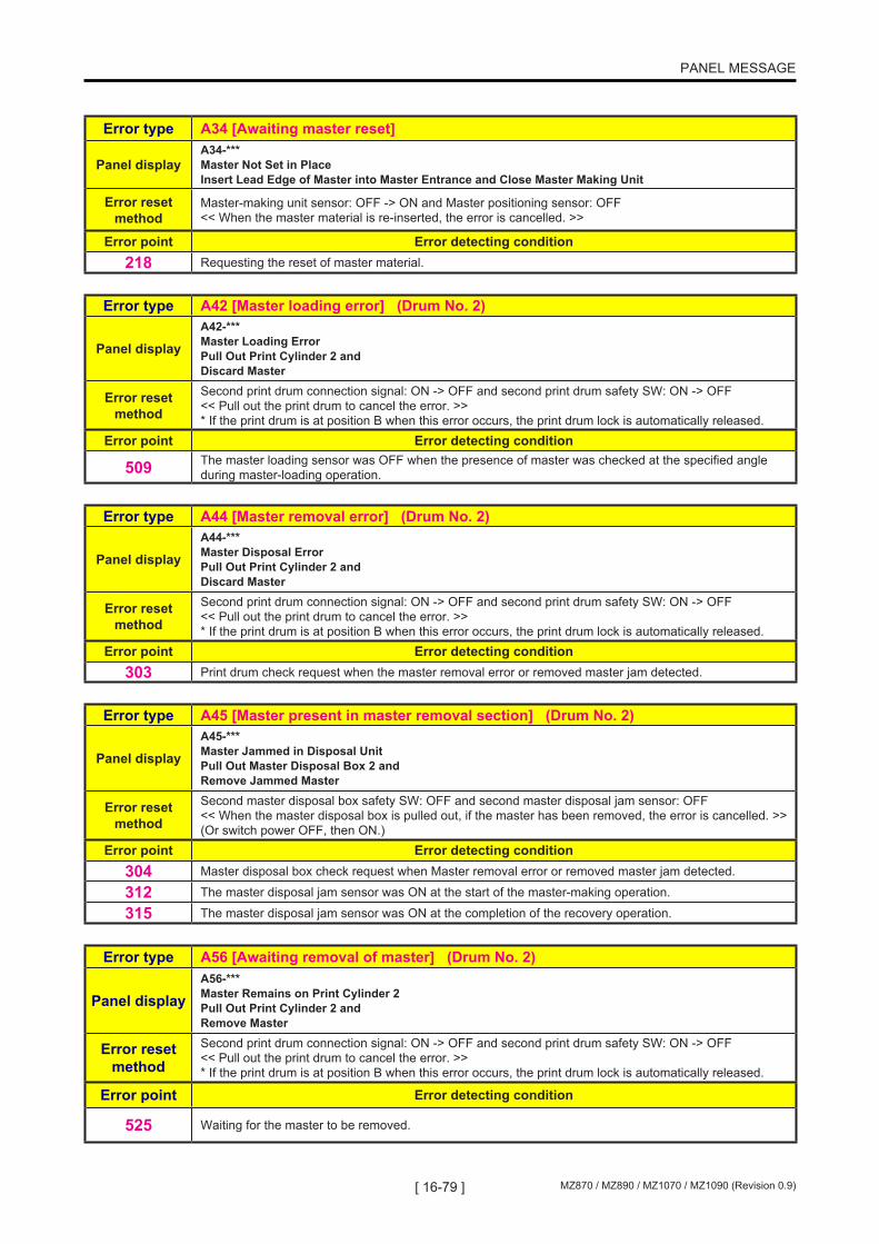
[ 16-79 ] MZ870 / MZ890 / MZ1070 / MZ1090 (Revision 0.9)
PANEL MESSAGE
Error type A34 [Awaiting master reset]
Panel displayA34-*** Master Not Set in Place Insert Lead Edge of Master into Master Entrance and Close Master Making Unit
Error reset method
Master-making unit sensor: OFF -> ON and Master positioning sensor: OFF << When the master material is re-inserted, the error is cancelled. >>
Error point Error detecting condition218 Requesting the reset of master material.
Error type A42 [Master loading error] (Drum No. 2)
Panel displayA42-*** Master Loading Error Pull Out Print Cylinder 2 and Discard Master
Error reset method
Second print drum connection signal: ON -> OFF and second print drum safety SW: ON -> OFF << Pull out the print drum to cancel the error. >> * If the print drum is at position B when this error occurs, the print drum lock is automatically released.
Error point Error detecting condition
509 The master loading sensor was OFF when the presence of master was checked at the specified angle during master-loading operation.
Error type A44 [Master removal error] (Drum No. 2)
Panel displayA44-*** Master Disposal Error Pull Out Print Cylinder 2 and Discard Master
Error reset method
Second print drum connection signal: ON -> OFF and second print drum safety SW: ON -> OFF << Pull out the print drum to cancel the error. >> * If the print drum is at position B when this error occurs, the print drum lock is automatically released.
Error point Error detecting condition303 Print drum check request when the master removal error or removed master jam detected.
Error type A45 [Master present in master removal section] (Drum No. 2)
Panel displayA45-*** Master Jammed in Disposal Unit Pull Out Master Disposal Box 2 and Remove Jammed Master
Error reset method
Second master disposal box safety SW: OFF and second master disposal jam sensor: OFF << When the master disposal box is pulled out, if the master has been removed, the error is cancelled. >> (Or switch power OFF, then ON.)
Error point Error detecting condition304 Master disposal box check request when Master removal error or removed master jam detected.
312 The master disposal jam sensor was ON at the start of the master-making operation.
315 The master disposal jam sensor was ON at the completion of the recovery operation.
Error type A56 [Awaiting removal of master] (Drum No. 2)
Panel displayA56-*** Master Remains on Print Cylinder 2 Pull Out Print Cylinder 2 and Remove Master
Error reset method
Second print drum connection signal: ON -> OFF and second print drum safety SW: ON -> OFF << Pull out the print drum to cancel the error. >> * If the print drum is at position B when this error occurs, the print drum lock is automatically released.
Error point Error detecting condition
525 Waiting for the master to be removed.

[ 16-80 ]MZ870 / MZ890 / MZ1070 / MZ1090 (Revision 0.9)
PANEL MESSAGE
Error type A07 [Paper feed error]
Error point Error detecting condition
409 The central transport sensor was OFF when the paper reached the central transport sensor, and the paper feed sensor was ON when the operation stopped (paper feed error).
412 The paper feed sensor switched OFF consecutively for n number of times at the time of the initial paper feed jam detection (no-paper feed error).
413 The paper feed sensor was ON when the paper left the paper feed sensor (extra-long paper error).Or the fuse for the Second paper feed motor is burnt.
418 The paper feed sensor was ON at the start of the operation.
443 The registration sensor was OFF at the time the paper reached the registration sensor.
444 The registration sensor was ON even though there was no paper.
Error type A08 [Paper jam] (Drum No. 1)
Error point Error detecting condition
410The central transport sensor was OFF at the timing when the paper should have arrived at the central transport sensor, and the Paper sensor was OFF when the machine stopped. (Either a paper jammed on the drum or the fuse for the Second paper feed motor is burnt).
Error type A09 [Paper ejection error]
Error point Error detecting condition
411 The paper ejection sensor was ON when the paper left the paper ejection sensor. Or the fuse for the Second paper feed motor is burnt.
417 The paper ejection sensor was ON at the start of the operation.
2-2. Jam errors (A**: Indicates the detail of J-type error)

[ 16-81 ] MZ870 / MZ890 / MZ1070 / MZ1090 (Revision 0.9)
PANEL MESSAGE
Error type A10 [AF original feed error]
Error point Error detecting condition
102
Original jam error resulting from pulled-out original. - The original IN sensor switched OFF while the original registration sensor and the original IN sensor were ON during scanning. - The original ejection sensor switched OFF before completion of scanning (prior to SIG_C output). - The original registration sensor switched OFF from the time of completion of leading edge insertion operation to the time of scanning start. * Error issued from AF.
103Original jam at the AF registration sensor (extra-long paper error). Simplex AF: The original registration sensor fails to switch OFF after the original IN sensor switched ON. Duplex AF: AF registration sensor did not go OFF after the original started to feed. * Error issued from AF.
105Original jam at the original IN sensor The original IN sensor fails to switch OFF after the original registration sensor switched OFF (max: movement of 84 mm). * Error issued from AF.
106
Original jam at the original OUT sensor Simplex AF: The original OUT sensor fails to switch OFF after the original IN sensor switched OFF. Duplex AF: The original OUT sensor fails to switch OFF after the original registration sensor switched OFF. * Error issued from AF.
107Original registration sensor non-arrival jam Original fails to reach the original registration sensor after the feed operation started. * Error issued from AF.
108Original IN sensor non-arrival jam Original fails to reach the original IN sensor after the scanning operation started (max.: movement of 42 mm). * Error issued from AF.
109Original OUT sensor non-arrival jam Simplex AF: Original fails to reach the original OUT sensor after the original IN sensor switched ON. Duplex AF: Oiginal fails to reach the original OUT sensor after the original started to feed. * Error issued from AF.
169 Original jammed in the AF unit due to the reason that the AF unit was opened during the operation.
178Original flipper sensor non-arrival jam Original fails to reach the Original flipper sensor after the original was fed. * Only on Duplex AF.
179Original jam at the original flipper sensor. Original flipper sensor fails to switch OFF after the original was fed. * Only on Duplex AF.
180 Gap between the originals not constant. * Only on Duplex AF.
Error type A25 [Central transport error]Error point Error detecting condition
419 The central transport sensor was ON at the start of the operation.
441 The central transport sensor was ON at the timing the paper should have left the central transport sensor (central transport error).
447 The paper ejection sensor did not detect the paper at the timing when the paper should have arrived, and when the machine stops, the central transport sensor was ON (central transport error).
455 Central transport error (during the recovery movement).
Error type A48 [Paper jam] (Drum No. 2)Error point Error detecting condition
410 The paper ejection sensor was OFF at the timing when the paper should have arrived to the sensor and when the machine stopped, the central transport sensor was OFF. (Paper jammed on Drum No.2)

[ 16-82 ]MZ870 / MZ890 / MZ1070 / MZ1090 (Revision 0.9)
PANEL MESSAGE
Error type B01 [Card counter: No card]
Panel display B01-*** Insert Card in Key/Card Counter
Error reset method Insert the card.
Error point Error detecting condition
730 Card counter: No card
Error type B21 [Storage memory: Read/write error]
Panel displayB21-*** !!System Error!! Turn Main Power SW OFF Then ON If Recovery has Failed, Call Service
Error reset method Switch power OFF, then ON.
Error point Error detecting condition
715 Storage memory access error.
Error type B22 [Job separator: Power OFF]
Panel displayB22-*** !! Job Separator is OFF !! Turn On Power Switch of it
Error reset method Press the Reset key. (Confirm that the job separator is switched ON.)
Error point Error detecting condition
721 With the tape separation setting switched ON, the job separator is in a Power OFF state when the Start key is pressed.
727 The BUSY signal remains at <L> (powe is switches OFF during job separator tape output) for more than 7 seconds after the cluster-A signal switches ON.
Error type B23 [Job separator: No-tape error]
Panel displayB23-*** No Paper Tape in Job Separator Replace Tape Roll
Error reset method Press the Reset key. (Confirm that the job separator is switched ON.)
Error point Error detecting condition
722 With the BUSY signal at <H> (Power ON) and the tape separation setting switched ON, the tape detection signal is at <H> (no tape) when the Start key is pressed.
723 The tape detection signal is at <H> (no tape) after the tape output command is issued, and the BUSY signal changed from <L> to <H> (after completion of operation).
3. Option errors (B**)

[ 16-83 ] MZ870 / MZ890 / MZ1070 / MZ1090 (Revision 0.9)
PANEL MESSAGE
Error type B24 [Job separator: Jam error]
Panel displayB24-*** Paper Tape Jam in Job Separator Remove Paper Tape
Error reset method Press the Reset key. (Confirm that the job separator jam is reset.)
Error point Error detecting condition
724 With the BUSY signal at <H> (Power ON) and the tape separation setting switched ON, the tape detection signal is at <L> (tape remaining) when the Start key is pressed.
725 The tape jam detection signal remains at <H> for more than 1.2 seconds after cluster-A signal switched ON (tape transport error).
726 The tape jam detection signal was at <L> when the BUSY signal changed from <L> to <H> or it remains at <L> for more than 7 seconds after the cluster-A signal switched ON (tape ejection error).
Error type B29 [USB Memory: Incompatible Device (HUB)]
Panel displayB29-*** Unable to Recognize (HUB) Remove Paper Tape
Error reset method Touch [Close] button, Press the Reset key, or remove the USB device.
Error point Error detecting condition
926 USB-HUB is inserted.
Error type B30 [USB Memory: Non-Compliant Device]
Panel displayB30-*** Unable to Recognize Remove Paper Tape
Error reset method Touch [Close] button, Press the Reset key, or remove the USB device.
Error point Error detecting condition
910 Non-Compliant USB device is inserted.

[ 16-84 ]MZ870 / MZ890 / MZ1070 / MZ1090 (Revision 0.9)
PANEL MESSAGE
Error type B31 [Network cable not connected]
Panel displayB31-*** !! No Linked Printer Detected !! Check Cable Connection and Power Supply for Linked Printer
Error reset method Press the Reset key.
Error point Error detecting condition
916 The network cable was not connected when the machine starts up.
920Error detected by NET-D (NAK received). * No response from communication destination, interruption by communication destination, TCP/IP not operating in the NET-D, or unauthorized interrupt received from the main unit, etc.
Error type B32 [NIC: External communication error]
Panel displayB32-*** !! No Linked Printer Detected !! Check Cable Connection and Power Supply for Linked Printer
Error reset method Press the Reset key. << Remove the cause of the error in the printer to cancel the error. >>
Error point Error detecting condition
914MIB information request error. * Transmission not possible after waiting 3 seconds (WAK), no response from communication destination, interruption by communication destination, TCP/IP not operating in the NET-D, or unauthorized interrupt received from the main unit, etc.
915 No MIB information returned. * No response from the NET-D (communication destination) for 50 seconds (error detected in main unit).
917 Network communication error.
Error type B33 [IP address setup error]
Panel displayB33-*** No IP Address Assigned to This Printer Contact Your Network Administrator
Error reset method Press the Reset key.
Error point Error detecting condition
931 The DHCP is ON, but the DHCP server cannot be found.

[ 16-85 ] MZ870 / MZ890 / MZ1070 / MZ1090 (Revision 0.9)
PANEL MESSAGE
Error type B34 [RLP: No-toner error]
Panel display B34-*** No Toner in Linked Printer
Error reset method Press the Reset key.
Error point Error detecting condition
919 No toner in the linked printer.
Error type B35 [RLP: Service error]
Panel display B35-*** Linked Printer in Error
Error reset method Press the Reset key.
Error point Error detecting condition
970 Service error in the linked printer.
Error type B38 [USB Memory: Folder making error]
Panel display B38-*** USB Memory Folder Error
Error reset method Touch [Close] button, Press the Reset key, or remove the USB device.
Error point Error detecting condition
911 Error in making RISO Folder.
Error type B39 [USB Memory: Read/Write error]
Panel display B39-*** USB Memory Read/Write Error
Error reset method Touch [Close] button, Press the Reset key, or remove the USB device.
Error point Error detecting condition
999 Error in USB file system.

[ 16-86 ]MZ870 / MZ890 / MZ1070 / MZ1090 (Revision 0.9)
PANEL MESSAGE
Error type C01 [Ink cartridge replacement] (Drum No. 1)
Panel displayC01-*** No Ink in Print Cylinder 1 Replace Ink Cartridge
Error reset method
First ink cartridge set SW: OFF -> ON << Install a new ink cartridge to cancel the error. >> Or first print drum safety SW: OFF, first print drum connection signal: OFF, and first print drum lock sensor: OFF << Pull out the print drum to cancel the error. >>
Error point Error detecting condition
512 The ink sensor does not switch ON when the inking operation is conducted for the set time (inkless).
563 The remaining volume information in the ink tag reached the maximum value.
574 Inkless error was generated 5 times for the same ink cartridge.
Error type C02 [Master roll replacement]
Panel displayC02-*** No Master Replace Master Roll
Error reset method Master-making unit sensor: OFF -> ON << Open and close the master-making unit to cancel the error. >>
Error point Error detecting condition
200 The 10-ms-interval master end check detected 2 consecutive times during the master transport.
240 The remaining volume information in the master tag reached the maximum value.
253 [No-master] error was generated twice for the same master.
Error type C03 [ Master disposal box full (Drum No. 1)
Panel displayC03-*** Master Disposal Box 1 is Full Empty Master Disposal Box
Error reset method Switch OFF the first master disposal box sensor OFF, then turn ON after waiting at least 5 seconds.
Error point Error detecting condition
308 After the master compression motor activates in the compressing direction, the compression detection switches ON before the FG count exceeds the specified volume.
311 The master compression software counter reached the full detection set count.
Error type C04 [No-paper error]
Panel display C04-*** Add Paper
Error reset method The paper detection sensor is ON.
Error point Error detecting condition
402 The paper detection sensor is OFF.
4. Consumable errors (C**)

[ 16-87 ] MZ870 / MZ890 / MZ1070 / MZ1090 (Revision 0.9)
PANEL MESSAGE
Error type C05 [Both master disposal boxes full]
Panel displayC05-*** Master Disposal Box 1 and 2 are Full Empty Both Master Disposal Boxes
Error reset method
Switch OFF the first master disposal box sensor, then switch it back ON after waiting at least 5 seconds. Switch OFF the second master disposal box sensor, then switch ON after waiting at least 5 seconds.
Error point Error detecting condition
317After the master compression motor on the first print drum side or second print drum side begins to apply a compression force, the compression detection activates and the other disposal box exceeds 90% capacity before the FG count exceeds the specified volume (Expected disposal box full).
Error type C41 [Ink cartridge replacement] (Drum No. 2)
Panel displayC41-*** No Ink in Print Cylinder 2 Replace Ink Cartridge
Error reset method
Second ink cartridge set SW: OFF -> ON << Install a new ink cartridge to cancel the error. >> Or second print drum safety SW: OFF, second print drum connection signal: OFF, and second print drum lock sensor: OFF << Pull out the print drum to cancel the error. >>
Error point Error detecting condition
512 The ink sensor does not turn ON when inking is performed for the set time (inkless).
563 The remaining volume information in the ink tag reached the maximum value.
574 An inkless error was generated 5 consecutive times for the same ink cartridge.
Error type C43 [Master disposal box full] (Drum No. 2)
Panel displayC43-*** Master Disposal Box 2 is Full Empty Master Disposal Box
Error reset method Switch OFF the second master disposal box sensor, then switch back ON after waiting at least 5 seconds.
Error point Error detecting condition
308 After the master compression motor activates in the compressing direction, the compression detection switches ON before the FG count exceeds the specified volume.

[ 16-88 ]MZ870 / MZ890 / MZ1070 / MZ1090 (Revision 0.9)
PANEL MESSAGE
Error type D01 [Print drum not installed] (Drum No. 1)
Panel display D01-*** Set Print Cylinder in Place
Error reset method
First print drum safety SW: ON, first print drum connection signal: ON, and first print drum lock sensor: ON << Install the print drum to clear the error. >>
Error point Error detecting condition526 The print drum is removed. (The connection signal, safety SW, and lock sensor are OFF.)
527 The print drum connection signal is OFF after the print drum is installed.
528 The print drum safety switch is OFF after the print drum is installed.
529 The print drum lock sensor is OFF after the print drum is installed (time-out during insertion: 5 sec).
530 The print drum connection signal does not switch OFF within 5 seconds after the print drum safety switch switches OFF, when the print drum is removed.
581 The drum safety switch turned OFF during machine operation.
Error type D02 [Print drum incompatibility] (Drum No. 1)
Panel displayD02-*** Wrong-Type Print Cylinder Installed in Cylinder Position 1 Replace with Correct Type
Error reset method Replace with the correct print drum. (The print drum code must match the machine model.)
Error point Error detecting condition532 The print drum is incompatible. (Drum code not correct)
580 The print drum is incompatible. (Drum style not correct)
Error type D03 [Ink cartridge not installed] (Drum No. 1)
Panel displayD03-*** Install Ink Cartridge in Print Cylinder 1
Error reset method First ink cartridge set SW: ON
Error point Error detecting condition
533 The ink cartridge set switch is OFF.
Error type D04 [Ink cartridge incompatibility] (Drum No. 1)
Panel display
D04-*** Wrong-type Ink Cartridge Installed in Cylinder 1 or Cannot Read Ink Info Replace Ink Cartridge or Contact Dealer/Riso Office
Error reset method Replace with a correct ink cartridge.
Error point Error detecting condition534 The ink cartridge is incompatible.
560 Error due to missing ink cartridge tag.
561 Ink tag communication error (tag communication error due to noise).
562 Abnormal ink tag information. Checksum error, verification error, storage of master information, etc.
564 Serial number mismatch detected during the periodic ink tag serial number check.
575 Software error involving ink tag. Antenna CH selection error, erroneous writing of data to write-protected area.
5. Set check errors (D**)
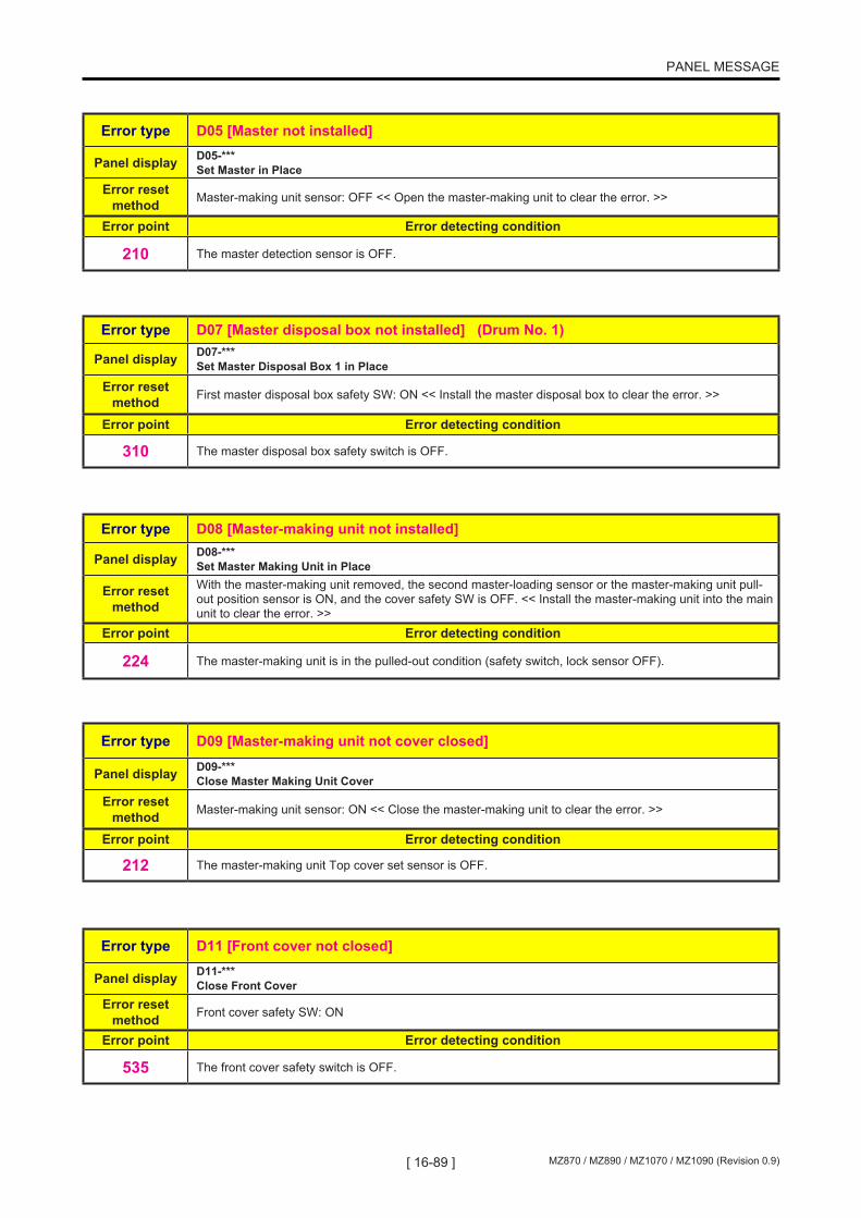
[ 16-89 ] MZ870 / MZ890 / MZ1070 / MZ1090 (Revision 0.9)
PANEL MESSAGE
Error type D05 [Master not installed]
Panel display D05-*** Set Master in Place
Error reset method Master-making unit sensor: OFF << Open the master-making unit to clear the error. >>
Error point Error detecting condition
210 The master detection sensor is OFF.
Error type D07 [Master disposal box not installed] (Drum No. 1)
Panel display D07-*** Set Master Disposal Box 1 in Place
Error reset method First master disposal box safety SW: ON << Install the master disposal box to clear the error. >>
Error point Error detecting condition
310 The master disposal box safety switch is OFF.
Error type D08 [Master-making unit not installed]
Panel display D08-*** Set Master Making Unit in Place
Error reset method
With the master-making unit removed, the second master-loading sensor or the master-making unit pull-out position sensor is ON, and the cover safety SW is OFF. << Install the master-making unit into the main unit to clear the error. >>
Error point Error detecting condition
224 The master-making unit is in the pulled-out condition (safety switch, lock sensor OFF).
Error type D09 [Master-making unit not cover closed]
Panel display D09-*** Close Master Making Unit Cover
Error reset method Master-making unit sensor: ON << Close the master-making unit to clear the error. >>
Error point Error detecting condition
212 The master-making unit Top cover set sensor is OFF.
Error type D11 [Front cover not closed]
Panel display D11-*** Close Front Cover
Error reset method Front cover safety SW: ON
Error point Error detecting condition
535 The front cover safety switch is OFF.

[ 16-90 ]MZ870 / MZ890 / MZ1070 / MZ1090 (Revision 0.9)
PANEL MESSAGE
Error type D13 [Machine rear cover not closed]
Panel displayD13-*** Rear Cover of Main Body is Off Call Service
Error reset method Rear cover safety SW: ON
Error point Error detecting condition
009 The rear cover of the main unit is not closed. (The rear cover safety switch is OFF.)
Error type D17 [Master incompatibility]
Panel display
D17-*** Wrong-type Master Installed or Cannot Read Master Info Replace Master Roll or Contact dealer/Riso office
Error reset method
Master-making unit safety SW: ON -> OFF and Master-making unit lock sensor: ON -> OFF << Pull out the master-making unit to clear the error. >>
Error point Error detecting condition236 The master is incompatible.
237 Error due to missing master tag.
238 Master tag communication error (tag communication error due to noise).
239 Abnormal master tag information. Checksum error, verification error, storage of ink information, etc.
241 Serial number mismatch detected during the periodic master tag serial number check.
256 Software error involving master tag. Antenna CH selection error, erroneous writing of data to write-protected area.
Error type D18 [Print drum ready to pull-out] (Drum No. 1)
Panel display D18-*** Print Cylinder 1 has been Unlocked
Error reset method
First print drum connection signal: ON -> OFF and first print drum safety SW: ON -> OFF << Pull out the print drum to clear the error. >> Or Front cover set SW: ON << Close the front cover to clear the error. >> Or master-making unit release button: ON << Press the master-making unit release button to clear the error. >>
Error point Error detecting condition
522 The print drum is in the pull-out position. (The print drum lock solenoid is ON.)
Error type D19 [Master-making unit ready to pull out]
Panel display D19-*** Master Making Unit has been Unlocked
Error reset method
Second master-loading sensor: OFF; Master-making unit pull-out position sensor: OFF; and Cover safety SW: OFF Or master-making unit drawer cover safety SW: OFF -> ON
Error point Error detecting condition
223 The master-making unit is in the pull-out position (The master making unit lock solenoid ON).

[ 16-91 ] MZ870 / MZ890 / MZ1070 / MZ1090 (Revision 0.9)
PANEL MESSAGE
Error type D20 [Master-making unit drawer cover not closed]
Panel display D20-*** Close Master Making Unit Access Cover
Error reset method Master-making unit drawer cover safety SW: OFF -> ON
Error point Error detecting condition
254The master-making unit drawer cover is not in position. (Master-making unit removed (second master-loading position sensor: ON or master-making unit pull-out position sensor: ON) and cover safety SW: OFF)
Error type D21 [Master-making unit drawer cover ready to open]
Panel displayD21-*** Ready to Open Master Making Unit Access Cover
Error reset method
Master-making unit drawer cover safety SW: ON -> OFF Or Pull-out position sensor: ON -> OFF
Error point Error detecting condition
255 The master-making unit drawer cover ready to open. (Master-making unit pull-out position sensor: ON and Cover safety SW: ON)
Error type D22 [Print drum pull-out command] (Drum No. 1)
Panel display
D22-*** Print Cylinder 1 is not Set in Place Press Cylinder Release Button and Pull Out Print Cylinder Once after Button Lights
Error reset method
First print drum safety SW: OFF; first print drum connection signal: OFF; and first print drum lock sensor: OFF
Error point Error detecting condition
531 The print drum lock sensor is ON when the print drum lock solenoid is ON. (The check is performed 100 ms after the print drum lock solenoid switches ON.)
540 Data cannot be written to or read from the EEPROM on the print drum. (EEPROM cannot be accessed.)
542 CRC error in the EEPROM on the print drum (data error in the EEPROM).
577 The print drum is not set into position properly.
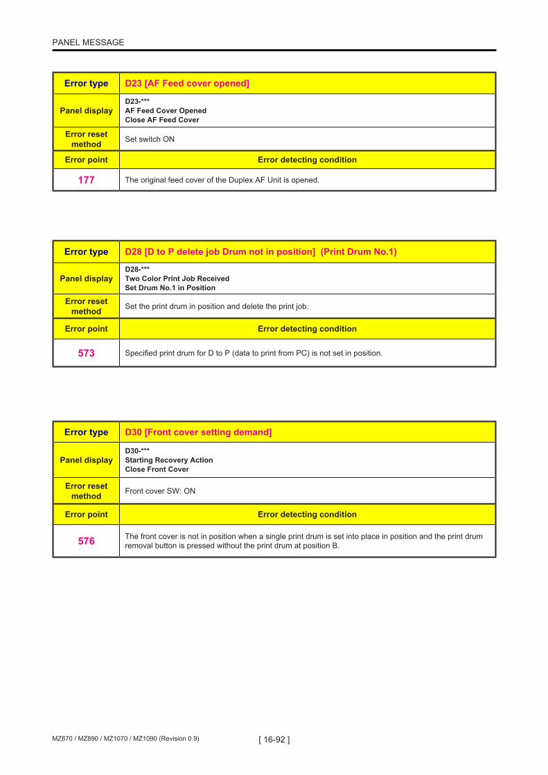
[ 16-92 ]MZ870 / MZ890 / MZ1070 / MZ1090 (Revision 0.9)
PANEL MESSAGE
Error type D23 [AF Feed cover opened]
Panel displayD23-*** AF Feed Cover Opened Close AF Feed Cover
Error reset method Set switch ON
Error point Error detecting condition
177 The original feed cover of the Duplex AF Unit is opened.
Error type D28 [D to P delete job Drum not in position] (Print Drum No.1)
Panel displayD28-*** Two Color Print Job Received Set Drum No.1 in Position
Error reset method Set the print drum in position and delete the print job.
Error point Error detecting condition
573 Specified print drum for D to P (data to print from PC) is not set in position.
Error type D30 [Front cover setting demand]
Panel displayD30-*** Starting Recovery Action Close Front Cover
Error reset method Front cover SW: ON
Error point Error detecting condition
576 The front cover is not in position when a single print drum is set into place in position and the print drum removal button is pressed without the print drum at position B.

[ 16-93 ] MZ870 / MZ890 / MZ1070 / MZ1090 (Revision 0.9)
PANEL MESSAGE
Error type D41 [Print drum not installed] (Drum No. 2)
Panel display D41-*** Set Print Cylinder 2 in Place
Error reset method
Second print drum safety SW: ON, second print drum connection signal: ON, and second print drum lock sensor: ON << Install the print drum to clear the error. >>
Error point Error detecting condition526 The print drum has been pulled out. (The connection signal, safety SW, and lock sensor are OFF.)
527 The print drum connection signal is OFF after the print drum is installed.
528 The print drum safety switch is OFF after the print drum is installed.
529 The print drum lock sensor is OFF after the print drum is installed (time-out during insertion: 5 sec).
530 The print drum connection signal does not switch OFF within 5 seconds after the print drum safety switch switched OFF when the print drum is removed.
581 The print drum safety switch turned OFF during machine operation.
Error type D42 [Print drum incompatibility] (Drum No. 2)
Panel displayD42-*** Wrong-Type Print Cylinder Installed in Cylinder Position 2 Replace with Correct Type
Error reset method Replace with the correct print drum. (The print drum code must match the machine model.)
Error point Error detecting condition
532 The print drum is incompatible. (Drum code is not correct)
580 The print drum is incompatible. (Drum style is not correct)
Error type D43 [Ink cartridge not installed] (Drum No. 2)
Panel displayD43-*** Install Ink Cartridge in Print Cylinder 2
Error reset method Second ink cartridge set SW: ON
Error point Error detecting condition
533 The ink cartridge set switch is OFF.
Error type D44 [Ink cartridge incompatibility] (Drum No. 2)
Panel display
D44-*** Wrong-type Ink Cartridge Installed in Cylinder 2 or Cannot Read Ink Info Replace Ink Cartridge or Contact Dealer/Riso Office
Error reset method Replace with the correct ink cartridge.
Error point Error detecting condition534 The ink cartridge is incompatible.
560 Error due to missing ink cartridge tag.
561 Ink tag communication error (tag communication error due to noise).
562 Abnormal ink tag information. Checksum error, verification error, storage of master information, etc.
564 Serial number mismatch detected during periodic ink tag serial number check.
575 Software error involving ink tag. Antenna CH selection error, erroneous writing of data to write-protected area.

[ 16-94 ]MZ870 / MZ890 / MZ1070 / MZ1090 (Revision 0.9)
PANEL MESSAGE
Error type D47 [Master disposal box not installed] (Drum No. 2)
Panel display D47-*** Set Master Disposal Box 2 in Place
Error reset method Second master disposal box safety SW: ON << Install the master disposal box to clear the error. >>
Error point Error detecting condition
310 The master disposal box safety switch is OFF.
Error type D58 [Print drum ready to pull-out] (Drum No. 2)
Panel display D58-*** Print Cylinder 2 has been Unlocked
Error reset method
Second print drum connection signal: ON -> OFF and second print drum safety SW: ON -> OFF << Pull out the print drum to clear the error. >> Or front cover SW: ON << Close the front cover to clear the error. >> Or master-making unit release button: ON << Press the master-making unit release button to clear the error. >>
Error point Error detecting condition
522 The print drum is in the pull-out position. (The print drum lock solenoid is ON.)
Error type D62 [Print drum pull-out command] (Drum No. 2)
Panel display
D62-*** Print Cylinder 2 is not Set in Place Press Cylinder Release Button and Pull Out Print Cylinder Once after Button Lights
Error reset method
Second print drum safety SW: OFF; second print drum connection signal: OFF; and second print drum lock sensor: OFF
Error point Error detecting condition
531 The print drum lock sensor is ON when the print drum lock solenoid is ON. (The check is performed 100 ms after the print drum lock solenoid switches ON.)
540 Data cannot be written to or read from the EEPROM on the print drum. (EEPROM cannot be accessed.)
542 CRC error in the EEPROM on the print drum (data error in the EEPROM).
577 The print drum is not set in position properly.
Error type D68 [D to P delete job Drum not in position] (Print Drum No.2)
Panel displayD68-*** Two Color Print Job Received Set Drum No.2 in Position
Error reset method Set the print drum in position and delete the print job.
Error point Error detecting condition
573 Specified print drum for D to P (data to print from PC) is not set in position.
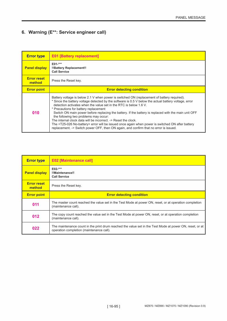
[ 16-95 ] MZ870 / MZ890 / MZ1070 / MZ1090 (Revision 0.9)
PANEL MESSAGE
Error type E01 [Battery replacement]
Panel displayE01-*** !!Battery Replacement!! Call Service
Error reset method Press the Reset key.
Error point Error detecting condition
010
Battery voltage is below 2.1 V when power is switched ON (replacement of battery required). * Since the battery voltage detected by the software is 0.5 V below the actual battery voltage, error detection activates when the value set in the RTC is below 1.6 V. * Precautions for battery replacement Switch ON main power before replacing the battery. If the battery is replaced with the main unit OFF the following two problems may occur: The internal clock data will be incorrect. -> Reset the clock. The <T25-026 No-battery> error will be issued once again when power is switched ON after battery replacement. -> Switch power OFF, then ON again, and confirm that no error is issued.
Error type E02 [Maintenance call]
Panel displayE02-*** !!Maintenance!! Call Service
Error reset method Press the Reset key.
Error point Error detecting condition
011 The master count reached the value set in the Test Mode at power ON, reset, or at operation completion (maintenance call).
012 The copy count reached the value set in the Test Mode at power ON, reset, or at operation completion (maintenance call).
022 The maintenance count in the print drum reached the value set in the Test Mode at power ON, reset, or at operation completion (maintenance call).
6. Warning (E**: Service engineer call)
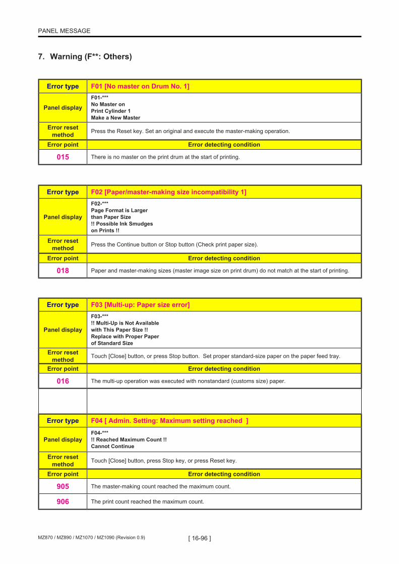
[ 16-96 ]MZ870 / MZ890 / MZ1070 / MZ1090 (Revision 0.9)
PANEL MESSAGE
Error type F01 [No master on Drum No. 1]
Panel displayF01-*** No Master on Print Cylinder 1 Make a New Master
Error reset method Press the Reset key. Set an original and execute the master-making operation.
Error point Error detecting condition
015 There is no master on the print drum at the start of printing.
Error type F02 [Paper/master-making size incompatibility 1]
Panel display
F02-*** Page Format is Larger than Paper Size !! Possible Ink Smudges on Prints !!
Error reset method Press the Continue button or Stop button (Check print paper size).
Error point Error detecting condition
018 Paper and master-making sizes (master image size on print drum) do not match at the start of printing.
Error type F03 [Multi-up: Paper size error]
Panel display
F03-*** !! Multi-Up is Not Available with This Paper Size !! Replace with Proper Paper of Standard Size
Error reset method Touch [Close] button, or press Stop button. Set proper standard-size paper on the paper feed tray.
Error point Error detecting condition
016 The multi-up operation was executed with nonstandard (customs size) paper.
Error type F04 [ Admin. Setting: Maximum setting reached ]
Panel displayF04-*** !! Reached Maximum Count !! Cannot Continue
Error reset method Touch [Close] button, press Stop key, or press Reset key.
Error point Error detecting condition
905 The master-making count reached the maximum count.
906 The print count reached the maximum count.
7. Warning (F**: Others)

[ 16-97 ] MZ870 / MZ890 / MZ1070 / MZ1090 (Revision 0.9)
PANEL MESSAGE
Error type F06 [ N-Up: Incorrect paper size ]
Panel display
F06-*** !! N-Up is Not Available with This Paper Size !! Replace with Proper Paper of Standard Size
Error reset method Press the Close button. Set standard-size paper on the paper feed tray.
Error point Error detecting condition
004 The multi-up operation was executed with nonstandard (customs size) paper.
Error type F07 [ N-Up: Incorrect original size ]
Panel display
F07-*** !! Multi-Up is Not Available with This Original Size !! Replace with Original of Proper Size
Error reset method Press the Reset button or Stop button. Use correct size original.
Error point Error detecting condition
023 N-Up operation was executed with wrong size original or custom size original.
Error type F09 [ Booklet: Incorrect paper size ]
Panel display
F09-*** !! Booklet is Not Available with This Paper Size !! Replace with Original of Proper Size
Error reset method
Touch [Close] button, or press Stop button. Set proper standard-size paper on the paper feed tray.
Error point Error detecting condition
810 Booklet operation was executed with wrong size non-standard (customs size) paper.
Error type F10 [Paper/master-making size incompatibility 2]
Panel display
F10-*** Page Format is Larger than Paper Size !! Possible Ink Smudges on Prints !! (Continue->PROOF Key)
Error reset method Press the Continue button or Stop button. (Check print paper size.)
Error point Error detecting condition
021 Paper and master-making sizes (image size on print drum) do not match at the start of proof printing.

[ 16-98 ]MZ870 / MZ890 / MZ1070 / MZ1090 (Revision 0.9)
PANEL MESSAGE
Error type F11 [Auto size reproduction disabled (falls outside range of possible size reproduction)]
Panel displayF11-*** !! Original Size Exceeds Limitation of Booklet !! Specify the original size
Error reset method Press the Reset key or Stop key.
Error point Error detecting condition
717 When Booklet was selected, the original size was out of range or not in standard size.
Error type F13 [4P Booklet was selected with wrong size paper on the paper feed tray]
Panel display
F13-*** !! 4P booklet is not available with this paper size !! Replace with proper paper of standard size
Error reset method Touch the [Close] key, or press the Reset or Stop key. Place appropriate size paper on feed tray.
Error point Error detecting condition
718 4P Booklet was selected with non-standard size paper on the paper feed tray.
Error type F14 [4P Booklet was selected with wrong size original]
Panel displayF14-*** !! Original size exceeds limitation of 4P booklet !! Specify the original size
Error reset method Press the Reset or Stop key.
Error point Error detecting condition
719 When Booklet was selected, the original size was out of range or not in standard size.

[ 16-99 ] MZ870 / MZ890 / MZ1070 / MZ1090 (Revision 0.9)
PANEL MESSAGE
Error type F20 [Binding margin: Wrong paper size ]
Panel display
F20-*** !! Reproduction Cannot be made with this paper size !! Replace with proper paper of standard size
Error reset method Touch the [Close] key, or press the Reset or Stop key. Place appropriate size paper on feed tray.
Error point Error detecting condition
30 Wrong size paper or non-stadard size paper is used for Binding margin with auto reduce-reproduction enabled.
Error type F24 [Auto size reproduction disabled (falls outside range of possible size reproduction)]
Panel display
F24-*** !! Images may not fit in Frame of Paper with This Reproduction Size !! Re-perform the size setting
Error reset method Press the Reset key. (Manually enter the size reproduction setting.)
Error point Error detecting condition
037 Size reproduction setting falls outside the permissible range when the operation started based on the auto size reproduction setting.
Error type F30 [Multiple feed check]
Panel displayF30-*** !! Possible Multiple Paper Feed !! Check Printed Copies
Error reset method Press the Multiple Feed Detection OFF button or Reset key.
Error point Error detecting condition
425 Multiple feed with the first sheet.
426 Multiple feed.

[ 16-100 ]MZ870 / MZ890 / MZ1070 / MZ1090 (Revision 0.9)
PANEL MESSAGE
Error type F32 [Storage memory: No space available]
Panel displayF32-*** !! The Data Storage Area has Become Full !! Clear Old Storage Data
Error reset method Press the Reset key. (Check the available capacity.)
Error point Error detecting condition
713 Inadequate storage memory during data write.
Error type F33 [Storage memory: No space available]
Panel display
F33-*** !! The file size is too large to store on USB flash drive !! Change the USB flash drive or delete some files to make spaces
Error reset method Touch the [Cancel] key, or press the Reset or Stop key.
Error point Error detecting condition
913 Inadequate USB flash drive memory during data write.
Error type F37 [Combined use of book mode and AF not possible]
Panel display
F37-*** !! Book Shadow Editor is Not Available with ADF !! Place Original on Stage Glass
Error reset method Press the Close button.
Error point Error detecting condition
050 With book mode set, an original was found on the AF at the start of the master-making operation.
Error type F43 [DtoP original/paper incompatibility]
Panel display
F43-*** !! Unmatched Size-- Current Page and Printing Paper !! Check Paper Size
Error reset method Press the Continue button or Stop button. (Check print paper size.)
Error point Error detecting condition
902 Paper and original sizes do not correspond at the start of DtoP master-making.

[ 16-101 ] MZ870 / MZ890 / MZ1070 / MZ1090 (Revision 0.9)
PANEL MESSAGE
Error type F44 [Auto size reproduction disabled (exceeds original size detection range)]
Panel display
F44-*** !! No Auto Reproduction with This Original and Printing Paper !! Select Size Manually
Error reset method Touch the [Cancel] key, or press the Reset or Stop key. (Manually enter the size reproduction setting.)
Error point Error detecting condition
901 The original size detection failed. (The original did not conform to the detection specification.)
Error type F45 [Presence of original unknown/no original]
Panel displayF45-*** Original Undetected Reset Original
Error reset method Reset the original. Press the Continue button or Stop button.
Error point Error detecting condition
954 Master-making operation or RLP output was executed with the auto tray or auto size reproduction setting set to ON, and the presence of an original could not be detected.
959 Master-making operation or RLP output was executed without an original.
981 When the Next button was clicked on the multi-up count entry screen of Multi-up Wizard, no original was detected.
Error type F46 [Print drum color not matching with DtoP job color] (Drum No. 1)
Panel display
F46-*** !! Unmatched Color -- Data Color and Cylinder Color 1 !! Change Print Cylinder Color: (Color name)
Error reset method Press the Reset key or the Continue button. (Replace the print drum.)
Error point Error detecting condition
903 The color of the print drum fails to match between the color specified for DtoP job and the color set for the specified print mode.
Error type F47 [Combined use of AF and postcard size reproduction not possible]
Panel display
F47-*** [A4->Card] Reproduction is Not Available in combination with ADF Place Original on Stage Glass
Error reset method Remove the original from the AF and press the Close button.
Error point Error detecting condition
904 Master-making operation or RLP output was performed with <A4 to Postcard> size reproduction selected and original set on the AF.

[ 16-102 ]MZ870 / MZ890 / MZ1070 / MZ1090 (Revision 0.9)
PANEL MESSAGE
Error type F48 [Multi-up: Outside original size detection range]
Panel displayF48-*** Original Size Exceeds Limitation of Multi-Up Specify Original Size
Error reset method Press the Reset key.
Error point Error detecting condition
955 Multi-up is selected with non-applicable original size or customs size original.
Error type F49 [Multi-up: No original when Start key pressed]
Panel displayF49-*** Original Undetected Reset Original
Error reset method Press the Stop button.
Error point Error detecting condition
989 No original is detected when the Enter key is pressed for the single original/multi-original multi-up setting.
Error type F52 [Use of RLP mode not possible (RLP information not acquired)]
Panel displayF52-*** Acquiring Linked Printer Configuration Data Please Wait a Moment
Error reset method Press the Close button.
Error point Error detecting condition
912 RLP mode cannot be used. (RLP information has not been acquired.)
Error type F58 [Use of RLP mode not possible (NET-D initialization in process)]
Panel displayF58-*** Starting Up RISORINC-NET Please Wait a Moment
Error reset method Press the Close button.
Error point Error detecting condition
927 RLP mode cannot be used. (The NET-D is being initialized.)

[ 16-103 ] MZ870 / MZ890 / MZ1070 / MZ1090 (Revision 0.9)
PANEL MESSAGE
Error type F60 [RLP auto-link/master-making continuation confirmation (when printing quantity is 0)]
Panel display
F60-*** !! Number of Copies is set to “0”!! Printing Operation will Start on this Printer (Continue -> START key)
Error reset method Press the Start key or Stop button.
Error point Error detecting condition
929 Confirmation of auto-link operation/master-making continuation (when printing quantity is 0).
Error type F61 [RLP paper/original size incompatibility]
Panel displayF61-*** Set Proper Paper Size in the Linked Printer
Error reset method Select paper using Manual Feed or Paper Selection.
Error point Error detecting condition
930 RLP paper/original size is incompatible.
Error type F62 [RLP auto-link/RLP error]
Panel display
F62-*** !!Auto-Link Operation is Not Available!! Specified Linked Printer may be in Error or Turned OFF
Error reset method Press the Stop button
Error point Error detecting condition
956 Error generated on the RLP side during RLP auto-link operation.
Error type F63 [RLP auto tray selection/nonstandard-size original]
Panel display
F63-*** !! No Auto Paper Size Selection with Irregular Size Original !! Select Paper Size and then Restart
Error reset method Press the Reset key. (Manually select paper.)
Error point Error detecting condition
971 RLP output was performed with a nonstandard-size original and auto paper size selection.
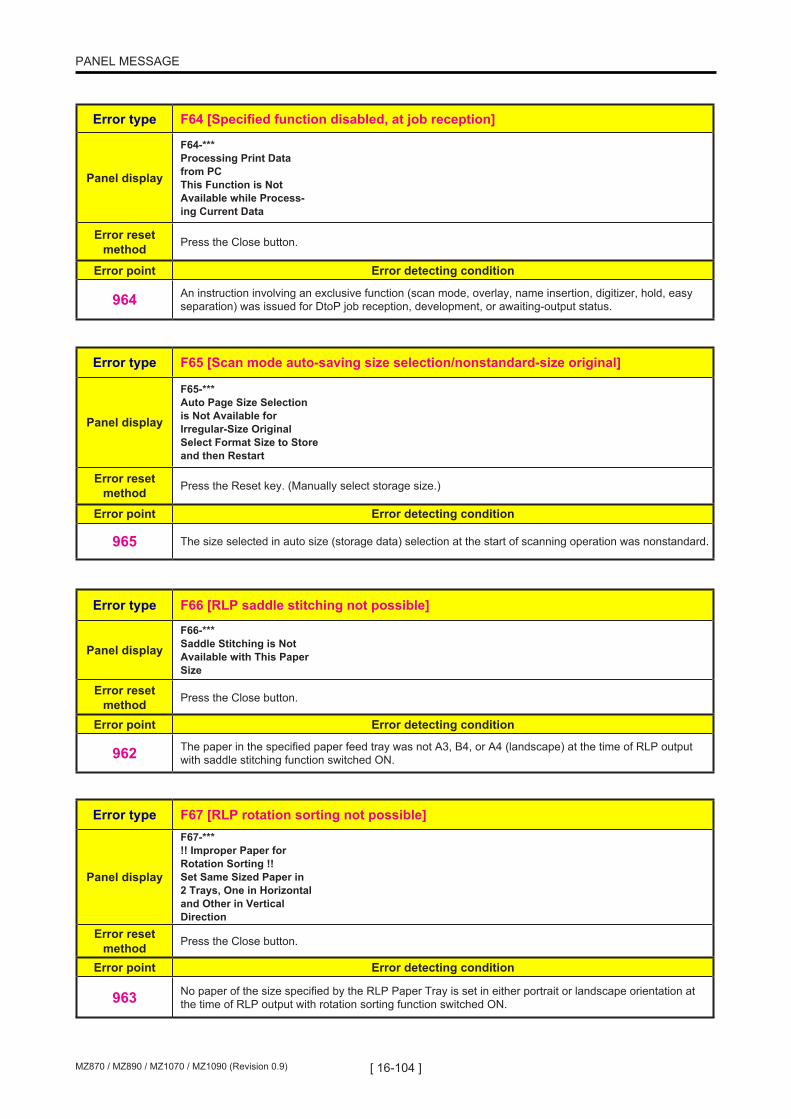
[ 16-104 ]MZ870 / MZ890 / MZ1070 / MZ1090 (Revision 0.9)
PANEL MESSAGE
Error type F64 [Specified function disabled, at job reception]
Panel display
F64-*** Processing Print Data from PC This Function is Not Available while Process- ing Current Data
Error reset method Press the Close button.
Error point Error detecting condition
964 An instruction involving an exclusive function (scan mode, overlay, name insertion, digitizer, hold, easy separation) was issued for DtoP job reception, development, or awaiting-output status.
Error type F65 [Scan mode auto-saving size selection/nonstandard-size original]
Panel display
F65-*** Auto Page Size Selection is Not Available for Irregular-Size Original Select Format Size to Store and then Restart
Error reset method Press the Reset key. (Manually select storage size.)
Error point Error detecting condition
965 The size selected in auto size (storage data) selection at the start of scanning operation was nonstandard.
Error type F66 [RLP saddle stitching not possible]
Panel displayF66-*** Saddle Stitching is Not Available with This Paper Size
Error reset method Press the Close button.
Error point Error detecting condition
962 The paper in the specified paper feed tray was not A3, B4, or A4 (landscape) at the time of RLP output with saddle stitching function switched ON.
Error type F67 [RLP rotation sorting not possible]
Panel display
F67-*** !! Improper Paper for Rotation Sorting !! Set Same Sized Paper in 2 Trays, One in Horizontal and Other in Vertical Direction
Error reset method Press the Close button.
Error point Error detecting condition
963 No paper of the size specified by the RLP Paper Tray is set in either portrait or landscape orientation at the time of RLP output with rotation sorting function switched ON.

[ 16-105 ] MZ870 / MZ890 / MZ1070 / MZ1090 (Revision 0.9)
PANEL MESSAGE
Error type F68 [Specified area/traced color separation: Excess number of specified areas]
Panel display
F68-*** !! Exceeding Number of Editing Areas Selected !! Deselect Some Areas and Redo Color Separation
Error reset method Press the Reset key.
Error point Error detecting condition
173 The number of specified areas for specified area/traced color separation exceeded the maximum value.
Error type F69 [Specified area/traced color separation: Distance of border for specified area longer than master-making size]
Panel displayF69-*** Cannot Read Selection Area Reset Original Correctly
Error reset method Press the Reset key.
Error point Error detecting condition
174 The distance of the border of the specified area for specified area/traced color separation exceeds the length against the master being made.
Error type F70 [Specified area/traced color separation: Image processing time-out error]
Panel displayF70-*** !! Complicated Area Form !! Re-circle Editing Areas and Redo Color Separation
Error reset method Press the Reset key.
Error point Error detecting condition
175 Image processing time-out error during specified area/traced color separation.
Error type F71 [No master on Drum No. 2]
Panel displayF71-*** No Master on Print Cylinder 2 Make a New Master
Error reset method Press the Reset key. Set an original and execute the master-making operation.
Error point Error detecting condition
015 No master is found on the print drum at the start of printing.

[ 16-106 ]MZ870 / MZ890 / MZ1070 / MZ1090 (Revision 0.9)
PANEL MESSAGE
Error type F72 [Hand-written/red-color separation: Image processing time-out error]
Panel displayF72-*** !! Complicated Area Form !! Re-circle Editing Areas and Redo Color Separation
Error reset method Press the Reset key.
Error point Error detecting condition
176 Image processing time-out error during hand-written/hand-written (ink)/red-color separation.
Error type F73 [Auto tray selection not possible, RLP tray designation disabled]
Panel display
F73-*** Paper Size cannot be Defined by Specified Reproduction Size Select Paper Size Manually
Error reset method Select paper using Manual Feed or Paper Selection. Press the Reset key.
Error point Error detecting condition
975 The specified fixed size reproduction and the detected original size do not match at the start of RLP. Or zoom/independent size reproduction was specified.
Error type F74 [50ppm not possible due to low temperature]
Panel displayF74-*** Printer Temperature is Low <150ppm> is Not Available [Cancel] [Continue]
Error reset method Press the Stop button or Continue button.
Error point Error detecting condition
980 150ppm printing was selected at temperatures below 15°C while using the second print drum.
Error type F75 [Combined use of specified area separation and AF not possible]
Panel display
F75-*** Specified Area Separation is Not Available in Combination with ADF Place Original on Stage Glass
Error reset method Press the Reset key.
Error point Error detecting condition
985 With specified area separation selected, an original was on the AF at the start of master-making.

[ 16-107 ] MZ870 / MZ890 / MZ1070 / MZ1090 (Revision 0.9)
PANEL MESSAGE
Error type F76 [Print drum color not matching with DtoP job color] (Drum No. 2)
Panel display
F76-*** !! Unmatched Color -- Data Color and Cylinder Color 2 !! Change Print Cylinder Color: (Color name)
Error reset method Press the Reset key or Continue button. (Replace the print drum.)
Error point Error detecting condition
903 The color of the print drum to be used fails to match with the DtoP job specified print color.
Error type F77 [Print drum color not matching with DtoP job color] (Drum No. 1)
Panel display
F77-*** !! Unmatched Color -- Data Color and Cylinder Colors !! Change Print Cylinders Color: (Color name)
Error reset method Press the Reset key or Continue button. (Replace the print drum.)
Error point Error detecting condition
903 The color of the print drum to be used fails to match with the DtoP job specified color.
Error type F78 [Digitizer: Stage cover open]
Panel display
F78-*** Close Stage Cover If original moves you may not get desired result
Error reset method Close the stage cover. Press the Close button.
Error point Error detecting condition
731 The stage cover was opened during the digitizing operation.
Error type F79 [Digitizer: No original during rescanning]
Panel display
F79-*** Set Original and Press Start Key Re-scanning will be Started to Add Image Processing
Error reset method Press the Start key or Stop button.
Error point Error detecting condition
732 No original was detected at the start of digitizer re-scanning.

[ 16-108 ]MZ870 / MZ890 / MZ1070 / MZ1090 (Revision 0.9)
PANEL MESSAGE
Error type F80 [Paper not compatible with dual-color printing]
Panel display
F80-*** Dual-Color Printing is Not Available for This Paper Size Load Paper Larger than B5 (Portrait )
Error reset method Press the Reset key. (Use paper larger than the minimum size.)
Error point Error detecting condition
966 The paper size is smaller than the minimum paper size for dual-color printing.
Error type F81 [Dual-color printing: Ink-saving setting only for one print drum]
Panel display
F81-*** Either of Masters is Made in Ink Saving Process Operate Dual-Color Printing?
Error reset method Press the Stop button or Continue button.
Error point Error detecting condition
967 At the start of dual-color printing operation, the master was made with one print drum in ink-saving master-making mode and the other in normal master-making mode.
Error type F82 [Paper not compatible for Drum No. 2 printing]
Panel display
F82-*** Printing is Not Available for This Paper Size with Print Cylinder 2 Set Print Cylinder to be Used in Cylinder Position 1 and Re-select Printing Mode
Error reset method Press the Reset key.
Error point Error detecting condition
974 The paper size is smaller than the minimum paper size for printing with Drum No. 2.
Error type F83 [Use of Drum No. 2 mode not possible]
Panel display
F83-*** Printing is Not Available for This Setting with Print Cylinder 2 Set Print Cylinder to be Used in Cylinder Position 1 and Re-select Printing Mode
Error reset method Press the Reset key.
Error point Error detecting condition
973 There is no confidential master on Drum No. 1 at the start of printing/proof-printing operation with Drum No. 2.

[ 16-109 ] MZ870 / MZ890 / MZ1070 / MZ1090 (Revision 0.9)
PANEL MESSAGE
Error type F85 [Scanning not possible: External CI not connected]
Panel display
F85-*** ! Scanning is Not Possible ! External CI is not Connected or Processing Connection Check Cable Connection
Error reset method Press the Close button or Start key.
Error point Error detecting condition
995 The PS7R is not connected.
997 Jog is unsuccessfully deleted from PS7R.
998 Sanned data unsuccessfully received by PS7R.
Error type F90 [Supply stock management (ink)]
Panel displayF90-*** Check Stock of Required Ink and Please Order If Needed
Error reset method Press the Close button.
Error point Error detecting condition
957 Stock management counter for the relevant color ink is over the Specified quantity (setting value).
Error type F91 [Supply stock management (master)]
Panel displayF91-*** Check Stock of Required Master and Please Order If Needed
Error reset method Press the Close button.
Error point Error detecting condition
958 Stock management counter for the master is over the Specified quantity (setting value).
Error type F93 [Reproduction ratio is larger than the master making area]
Panel displayF93-*** Present reproduction ratio may not fit in the master making area Please check Please Order If Needed
Error reset method Press START key to continue, or press CANCEL key to stop. (Change the reproduction ratio manually)
Error point Error detecting condition
936 With the reproduction ratio set to AUTO, the reproduction image size became larger than the master making area.

[ 16-110 ]MZ870 / MZ890 / MZ1070 / MZ1090 (Revision 0.9)
PANEL MESSAGE
Error type F94 [Protect confirmation (compulsory)]
Panel displayF94-*** - protect - The master will be removed Please Order If Needed
Error reset method Press START key.
Error point Error detecting condition
007 The protect function is active when the machine power is turned ON, waking up from sleep, or when the print drum is inserted in the machine.
Error type F95 [Protect confirmation]
Panel displayF95-*** - protect - The master will be removed Please Order If Needed
Error reset method Press START key to remove the master, or press STOP key to keep the master on the drum.
Error point Error detecting condition
008 The message displays after current job is finished with the protect function active.
Error type F96 [Admin. Mode: Due Date for the ID Counter Report]
Panel display
F96-*** Please inform this message to your administrator Due date for ID counter report
Error reset method Touch [Close] key, or Press Stop or Reset key.
Error point Error detecting condition
918 The due date came for the ID counter report set by the Admin. setting.
Error type F97 [Admin. Mode: Due Date for the Counter Report]
Panel displayF97-*** Please inform this message to your administrator Due date for counter report
Error reset method Touch [Close] key, or Press Stop or Reset key.
Error point Error detecting condition
928 The due date came for the counter report set by the Admin. setting.

[ 16-111 ] MZ870 / MZ890 / MZ1070 / MZ1090 (Revision 0.9)
PANEL MESSAGE
Error type H01 [General supply parameter input] (Drum No. 1)
Panel displayInk (Cylinder 1) Cannot Get Consumable Info Input Values Required
Error reset method Enter the parameters and press the Start key.
Error point Error detecting condition
566 Enter parameters, since first ink tag color information, steady-state viscosity information, and FP viscosity information are unreliable.
Error type H04 [General supply parameter input (master)]
Panel displayInk (Master) Cannot Get Consumable Info Input Values Required
Error reset method Enter the parameters and press the Start key.
Error point Error detecting condition
242 Enter parameters, since master tag sensitivity information, steady-state viscosity information, and FP viscosity information are unreliable.
Error type H07 [General supply parameter input] (Drum No. 2)
Panel displayInk (Cylinder 2) Cannot Get Consumable Info Input Values Required
Error reset method Enter parameters and press the Start key.
Error point Error detecting condition
571 Enter parameters, since second ink tag color information, steady-state viscosity information, and FP viscosity information are unreliable.
8. Parameter Errors (H**)

[ 16-112 ]MZ870 / MZ890 / MZ1070 / MZ1090 (Revision 0.9)
PANEL MESSAGE
Paper jam (including AF original feed error) generates an internal [A**] error. However, since this type of error is combined with another error code, the panel displays a [J**] error code.<**> in the [J**] error code is a value obtained by assigning a bit to each error (one of four types shown in the table below) subject to paper jam processing and adding the numeric values corresponding to the assigned bits.The detailed error code is displayed by pressing the < * > key on the Operation Panel.
Example: When <A10> and <A08> are generated, [J05] is displayed.
10. Errors Saved in Memory
9. J-type Error Display (J**)
Error type J** [Paper jam error]
Panel display
J** Paper Jam Remove Paper in Indicated Areas and Press [OK] Button
Error type Error name Bit Numeric value
A10 AF original feed error Bit 0 1
A09 Paper ejection error Bit 1 2
A08 Paper jam on print drum (No.1 Drum) Bit 2 4
A07 Paper feed error Bit 3 8
A25 Central transport error Bit 4 16
A48 Paper jam on print drum (No.2 Drum) Bit 5 32
The following errors are saved in memory and cannot be cleared simply by switching off the power.
Error type DescriptionA04 Master removal error on first print drum side
A44 Master removal error on second print drum side
A08 Paper jam on first print drum
A48 Paper jam on second print drum
A25 Central transport error
C01 First ink cartridge replacement
C41 Second ink cartridge replacement
C02 Master roll replacement
C03 First master disposal box full
C43 Second master disposal box full
C05 Both master disposal boxes full

[ 17-1 ] MZ870 / MZ890 / MZ1070 / MZ1090 (Revision 0.9)
OTHER PRECAUTIONS
CHAPTER 17: OTHER PRECAUTIONS
CONTENTS
1. Downloading the DSP Software ...........................................................17-2

[ 17-2 ]MZ870 / MZ890 / MZ1070 / MZ1090 (Revision 0.9)
OTHER PRECAUTIONS
1. Downloading the DSP Software
NOTE: The DSP Software is required to synchronize the Second Paper Feed Motor to the Main Motor. The DSP Software is download in the Extension-PCB2. If the Extension-PCB2 is replaced, the DSP Software must be downloaded.
The DSP Software changes the speed of the Second Paper Feed Motor when feeding the paper from the second paper feed area to the print drum, according to the print drum angle when the Timing Roller and Guide Roller start feeding the paper. This control action keeps the image print position constant on all the prints. The DSP Software also controls the Second Paper Feed Mo-tor speed the moment the print drum pinches the leading edge of the paper. When the leading edge of the paper arrives at the print drum, according to the paper size and to which print drum the paper is sent to, the trailing edge of the paper is still pinched by the Timing Roller and Guide Roller. The DSP Software makes sure that the Second Paper Feed Motor feeds the paper in the same speed as the print drum to ensure smooth paper feeding through the printing area to prevent smeared image which may occur if the Timing Roller and Guide Roller pull on the paper during the printing.
The DSP Software version should match with that of the Mechanical Control PCB and NeoROSA PCB firmware. The compatibility information on the firmware program versions will be issued at the same time when updated DSP Software is announced.
(1) With the appropriate firmware for the mechanical control PCB and for the NeoROASA PCB download-ed, turn ON the machine in test mode to confirm that the machine properly goes into Test Mode.
(2) Switch OFF the machine power and insert the download CF Card in an adopter or in USB Memory Stick, containing the DSP software.
(3) Launch Test Mode and run Test Mode No. 102 [DSP Download (Main, Secondary)].
(4) Check the operation panel and make sure that the download is completed (The download should take around one minute).
(5) Switch OFF the machine power and remove the CF card or USB memory stick.
(6) Launch Test Mode again and run Test Mode No. 126 (Optional Configuration Check). Check the soft-ware version on the display to confirm that the DSP Software is upgraded.
MZ7 & MZ9 Series contain the DSP Software in the Mechanical Control PCB.
MZ8 & MZ10 Series contain the DSP Software in the Extension-PCB2.

MZ870 / MZ890 / MZ1070 / MZ1090 (Revision 0.9)

MZ870 / MZ890 / MZ1070 / MZ1090 (Revision 0.9)
RISO MZ870/MZ890/MZ1070/MZ1090 Technical Manual<Differential information compared to the existing MZ7 & MZ9 Series.>
(Rev. 0.9)
Published May 2010Reproduction and duplication prohibited
Edited and published by: Overseas Technical Department, RISO KAGAKU CORPORATION
The contents of this manual are subject to change without notice
Related Documents