Risk Assessment for RAPEX General Information Product Product name: Portas giratórias detectoras de metais Product category: Description: Interferência eletromagnética Risk assessor First name: Alexsandro Nogueira Reis Last name: Reis Organisation: INMETRO Address: Product risks - Overview Scenario 1 : Low risk - Uma pessoa encontra-se perto de uma fonte de CEM, o corpo (sistema nervoso central) fica exposto ao CEM Scenario 2 : Low risk - A pele ou os olhos de uma pessoa são expostos a radiação emitida pelo produto Overall risk : Risco baixo Documento (0170900) SEI 0052600.010084/2018-61 / pg. 1

Welcome message from author
This document is posted to help you gain knowledge. Please leave a comment to let me know what you think about it! Share it to your friends and learn new things together.
Transcript
Risk Assessment for RAPEX
General Information
Product
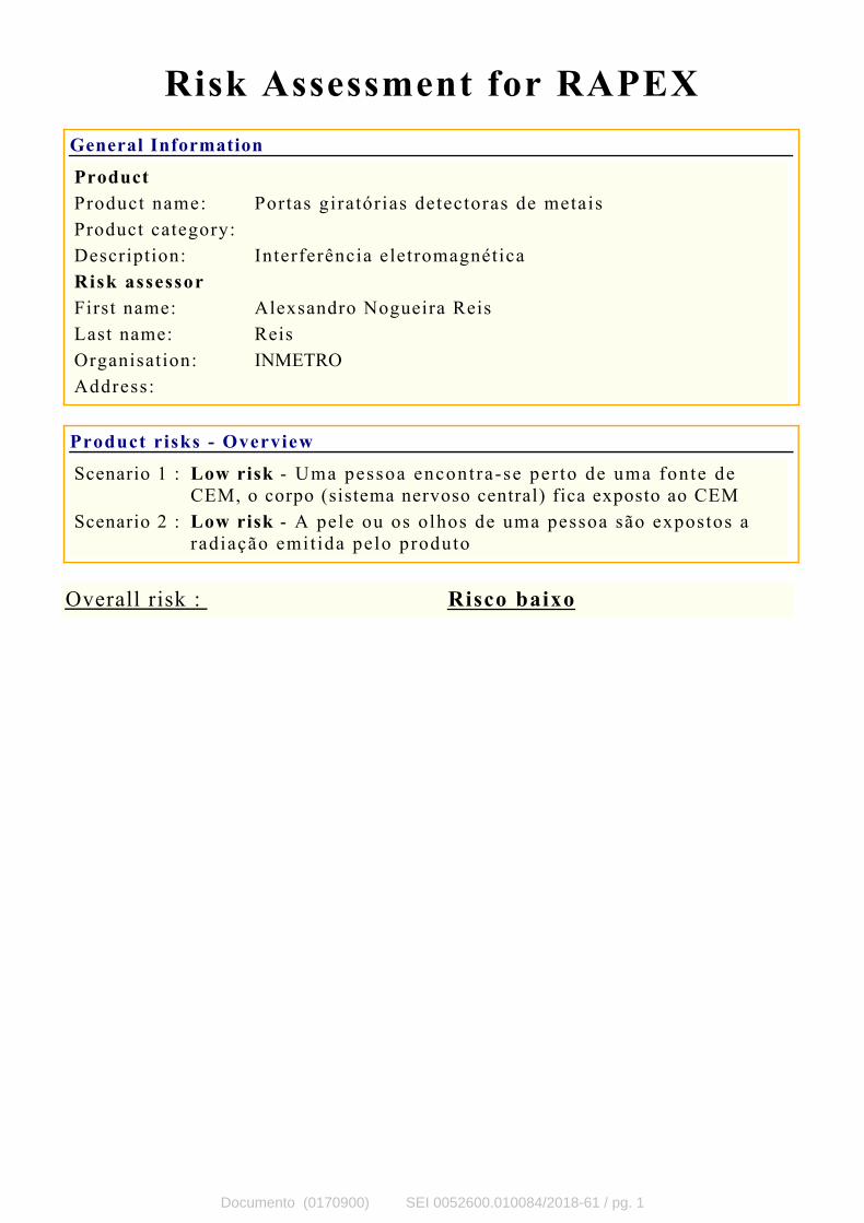
Product name: Portas giratórias detectoras de metais
Product category:
Description: Interferência eletromagnética
Risk assessor
First name: Alexsandro Nogueira Reis
Last name: Reis
Organisation: INMETRO
Address:
Product risks - Overview
Scenario 1 : Low risk - Uma pessoa encontra-se per to de uma fonte de
CEM, o corpo (sistema nervoso central) fica exposto ao CEM
Scenario 2 : Low risk - A pele ou os olhos de uma pessoa são expostos a
radiação emit ida pelo produto
Overall risk : Risco baixo
Documento (0170900) SEI 0052600.010084/2018-61 / pg. 1
anreis
Texto digitado
anreis
Texto digitado
anreis
Texto digitado
APÊNDICE II
anreis
Texto digitado
anreis
Texto digitado
anreis
Texto digitado
anreis
Texto digitado
anreis
Texto digitado
anreis
Texto digitado
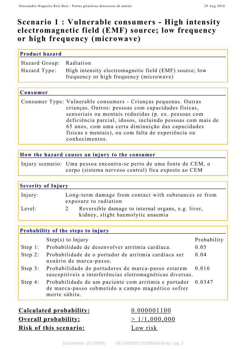
Scenario 1 : Vulnerable consumers - High intensityelectromagnetic field (EMF) source; low frequencyor high frequency (microwave)
Product hazard
Hazard Group: Radiat ion
Hazard Type: High intensity electromagnetic field (EMF) source; low
frequency or high frequency (microwave)
Consumer
Consumer Type: Vulnerable consumers - Crianças pequenas. Outras
crianças. Outros: pessoas com capacidades físicas,
sensoriais ou mentais reduzidas (p. ex. pessoas com
deficiência parcial, idosos, incluindo pessoas com mais de
65 anos, com uma certa diminuição das capacidades
físicas e mentais), ou com falta de experiência ou
conhecimentos .
How the hazard causes an injury to the consumer
Injury scenario: Uma pessoa encontra-se perto de uma fonte de CEM, o
corpo (sistema nervoso central) fica exposto ao CEM
Severity of Injury
Injury: Long-term damage from contact wi th substances or f rom
exposure to radiat ion
Level: 2 Reversible damage to internal organs, e.g. liver,
kidney, sl ight haemolytic anaemia
Probability of the steps to injury
Step(s) to Injury Probability
Step 1: Probabilidade de desenvolver arritmia cardíaca. 0 .05
Step 2: Probabil idade de o portador de arri tmia cardíaca ser
usuár io de marca-passo .
0 .04
Step 3: Probabi l idade de por tadores de marca-passo es tarem
suscepitíveis a interferências eletromagnéticas diversas.
0 .016
Step 4: Probabil idade de um paciente com arr i tmia e portador
de marca-passo submet ido a campo magnét ico sofrer
morte súbi ta .
0 .0347
Calculated probability: 0.000001100
Overall probability: > 1 /1 ,000 ,000
Risk of this scenario: Low risk
Alexsandro Nogueira Reis Reis : Portas giratórias detectoras de metais 29 Aug 2016
Documento (0170900) SEI 0052600.010084/2018-61 / pg. 2

Alexsandro Nogueira Reis Reis : Portas giratórias detectoras de metais 29 Aug 2016
Documento (0170900) SEI 0052600.010084/2018-61 / pg. 3

Scenario 2 : Vulnerable consumers - Ultravioletradiation
Product hazard
Hazard Group: Radiat ion
Hazard Type: Ultraviolet radiation
Consumer
Consumer Type: Vulnerable consumers - Crianças pequenas. Outras
crianças. Outros: pessoas com capacidades físicas,
sensoriais ou mentais reduzidas (p. ex. pessoas com
deficiência parcial, idosos, incluindo pessoas com mais de
65 anos, com uma certa diminuição das capacidades
físicas e mentais), ou com falta de experiência ou
conhecimentos .
How the hazard causes an injury to the consumer
Injury scenario: A pele ou os olhos de uma pessoa são expostos a radiação
emit ida pelo produto
Severity of Injury
Injury: Long-term damage from contact wi th substances or f rom
exposure to radiat ion
Level: 2 Reversible damage to internal organs, e.g. liver,
kidney, sl ight haemolytic anaemia
Probability of the steps to injury
Step(s) to Injury Probability
Step 1: Probabilidade de desenvolver arritmia cardíaca. 0 .05
Step 2: Probabil idade de o portador de arri tmia cardíaca ser
usuár io de marca-passo .
0 .04
Step 3: Probabi l idade de por tadores de marca-passo es tarem
suscepitíveis a interferências eletromagnéticas diversas.
0 .016
Step 4: Probabil idade de um paciente com arr i tmia e portador
de marca-passo submet ido a campo magnét ico sofrer
morte súbi ta .
0 .0347
Calculated probability: 0.000001100
Overall probability: > 1 /1 ,000 ,000
Risk of this scenario: Low risk
Alexsandro Nogueira Reis Reis : Portas giratórias detectoras de metais 29 Aug 2016
Documento (0170900) SEI 0052600.010084/2018-61 / pg. 4

5 4 3 2 1 0
GRAVIDADE (G) Nota Atribuída Gravidade Urgência Tendência
Extremo Alto Moderado Baixo máximo 24 25 23
5 4 2 1 1 Mínimo 3 3 2
Calçados de Segurança 17 4 5
Sim Não
3 0 3
Sim Não
4 0 4
Sim Não
4 0 0
Sim Não
4 0 4
Sim Não
4 2 4
TOTAL (G) 16
URGÊNCIA (U) Nota Atribuída
Sim Não
4 0 0
Sim Não
2 0 0
Sim Não
4 0 0
Sim Não
4 0 0
Curto Médio Longo
3 2 1 3
Sim Não
4 1 1
Sim Não
4 1 1
TOTAL (U) 5
TENDÊNCIA (T) Nota Atribuída
Sim Não
4 1 1
Sim Não
3 1 1
Não Sim
3 0 0
Sim Não
3 0 3
Sim Não
5 0 0
Sim Não
5 0 0
TOTAL (T) 5
400
Não Ação < 537
AIR 538 até 5370
Direto Desenvolvimento 5371 até 10800
APÊNDICE III
D) Inmetro tem competência
legal
A)Risco
D)Impacto Meio Ambiente
D) Apelo Midiático
B) Similares fora do país
C) Impacto sobre saúde
E) Práticas enganosas
F) Utilização por crianças e/ou
idosos
B) Pressão do Setor
C) Pressão Sociedade
E) O PAP apontou problemas
em relação ao objeto
Escores
PONTUAÇÃO DO PROBLEMA
MATRIZ GUT
Valor da Pontuação/ Tratamento
A)Problema já apresentado
antes (recorrente)
B) Acidente nos últimos 12
meses
C) Possivel resolução sem
Inmetro intervir
F) Diretriz Governamental/
Politica Pública
E) Prazo dos impactos
F) Não tratamento causa
impacto econômico
A)Pressão Política
G) Não tratamento causa
impacto social
0
5
10
15
20
25Gravidade
UrgênciaTendência
máximo
Mínimo
Calçados de
Segurança
Documento (0171036) SEI 0052600.010084/2018-61 / pg. 5
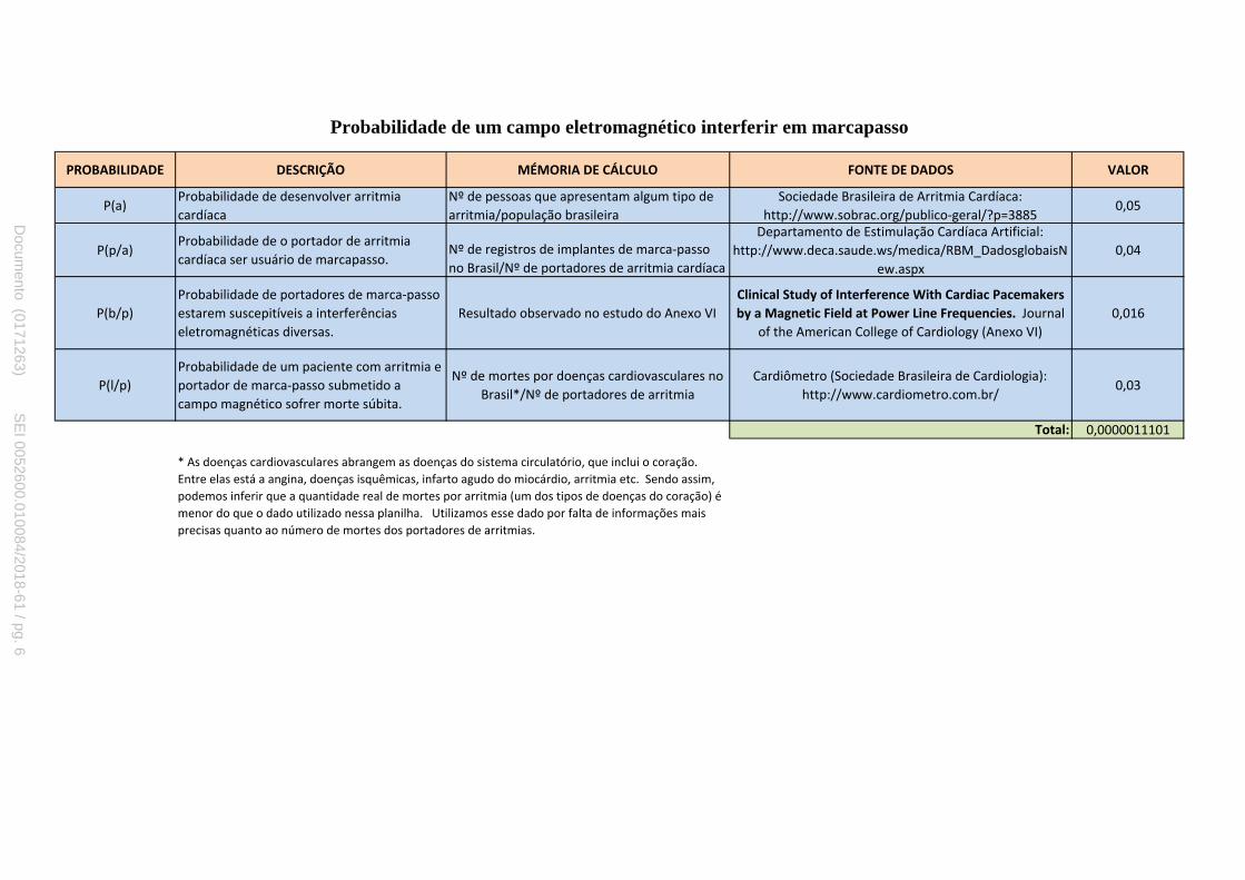
PROBABILIDADE DESCRIÇÃO MÉMORIA DE CÁLCULO FONTE DE DADOS VALOR
P(a)Probabilidade de desenvolver arritmia
cardíaca
Nº de pessoas que apresentam algum tipo de
arritmia/população brasileira
Sociedade Brasileira de Arritmia Cardíaca:
http://www.sobrac.org/publico-geral/?p=38850,05
P(p/a)Probabilidade de o portador de arritmia
cardíaca ser usuário de marcapasso.Nº de registros de implantes de marca-passo
no Brasil/Nº de portadores de arritmia cardíaca
Departamento de Estimulação Cardíaca Artificial:
http://www.deca.saude.ws/medica/RBM_DadosglobaisN
ew.aspx
0,04
P(b/p)
Probabilidade de portadores de marca-passo
estarem suscepitíveis a interferências
eletromagnéticas diversas.
Resultado observado no estudo do Anexo VI
Clinical Study of Interference With Cardiac Pacemakers
by a Magnetic Field at Power Line Frequencies. Journal
of the American College of Cardiology (Anexo VI)
0,016
P(l/p)
Probabilidade de um paciente com arritmia e
portador de marca-passo submetido a
campo magnético sofrer morte súbita.
Nº de mortes por doenças cardiovasculares no
Brasil*/Nº de portadores de arritmia
Cardiômetro (Sociedade Brasileira de Cardiologia):
http://www.cardiometro.com.br/0,03
Total: 0,0000011101
* As doenças cardiovasculares abrangem as doenças do sistema circulatório, que inclui o coração.
Entre elas está a angina, doenças isquêmicas, infarto agudo do miocárdio, arritmia etc. Sendo assim,
podemos inferir que a quantidade real de mortes por arritmia (um dos tipos de doenças do coração) é
menor do que o dado utilizado nessa planilha. Utilizamos esse dado por falta de informações mais
precisas quanto ao número de mortes dos portadores de arritmias.
Probabilidade de um campo eletromagnético interferir em marcapasso
Docum
ento (0171263) SE
I 0052600.010084/2018-61 / pg. 6
anreis
Texto digitado
APÊNDICE IV
anreis
Texto digitado

Frequência (GHz)Profundiade de
penetração (mm)
1 15,9
1,5 11,9
1,8 10,0
2,5 7,3
17
12
Profundida de penetração de onda eletromagnética na pele
Comprimento de onda (λ cm)
30
20
Documento (0171263) SEI 0052600.010084/2018-61 / pg. 7
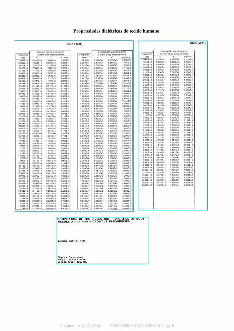
Propriedades dielétricas do tecido humano
Documento (0171263) SEI 0052600.010084/2018-61 / pg. 8

CIbAIM
EmsEvscfihaesemust
p
MFLwE
2
Journal of the American College of Cardiology Vol. 45, No. 6, 2005© 2005 by the American College of Cardiology Foundation ISSN 0735-1097/05/$30.00P
Cardiac Pacemakers
linical Study ofnterference With Cardiac Pacemakersy a Magnetic Field at Power Line Frequencieslexandre Trigano, MD,* Olivier Blandeau, BS,* Martine Souques, MD,† Jean Pierre Gernez, BS,‡
sabelle Magne, PHD‡arseille, Paris, and Moret-sur-Loing, France
OBJECTIVES This study examined the risk of interference by high magnetic flux density with permanentpacemakers.
BACKGROUND Several forms of electromagnetic energy may interfere with the functions of implantedpacemakers. No clinical study has reported specific and relevant information pertaining tomagnetic fields near power lines or electrical appliances.
METHODS A total of 250 consecutive tests were performed in 245 recipients of permanent pacemakersduring 12-lead electrocardiographic monitoring. A dedicated exposure system generated a50-Hz frequency and maximum 100-�T flux density, while the electrical field was kept atvalues on the order of 0.10 V/m.
RESULTS A switch to the asynchronous mode was recorded in three patients with devices programmedin the unipolar sensing configuration. A sustained mode switch was followed by symptomaticpacing inhibition in one patient. No effect on devices programmed in bipolar sensing wasobserved, except for a single interaction with a specific capture monitoring algorithm.
CONCLUSIONS The overall incidence of interaction by a magnetic field was low in patients tested with a widevariety of conventionally programmed pacemaker models. A magnetic field pulsed at powerfrequency can cause a mode switch and pacing inhibition in patients with devices pro-grammed in the unipolar sensing configuration. The risk of interference appears negligible inpatients with bipolar sensing programming. (J Am Coll Cardiol 2005;45:896–900) © 2005
ublished by Elsevier Inc. doi:10.1016/j.jacc.2004.10.072
by the American College of Cardiology Foundation
t1E(dip
M
PEStawoapmrfdpb
lectromagnetic interference (EMI) with implanted pace-akers has been studied in vitro and in several clinical
tudies or reported from anecdotal daily life observations.lectromagnetic interference may be observed near high-
oltage power lines and plants, transformers, or othertructures or may be caused by electrical appliances heldlose to the chest. Although interference by strong electricalelds has been widely reported, EMI from magnetic fieldsas not been studied as intensively. Strong magnetic fieldsre present in industrial or occupational environments andmitted in day-to-day life by household appliances andome electronic surveillance articles. The safe limits ofxposure to magnetic flux in recipients of implanted pace-akers remain to be established. Although simulations
sing a model of the human body have been presented, aingle, nondefinitive clinical study has been published onhis subject (1–3).
This study was designed to examine, in a large patientopulation, the behavior of implanted cardiac pacemakers in
From the *Department of Cardiology, Centre Hospitalier Universitaire Nord,arseille; †Department of Medical Studies, Electricité de France, EDF-Gaz de
rance, Paris; and ‡Electricité de France Research and Development, Electricalaboratories, Electromagnetic Compatibility Group, Moret-sur-Loing, France. Thisork was supported by a grant from Le Réseau de Transport de l’Electricité andlectricité de France, Department of Medical Studies, Paris, France.
oManuscript received August 22, 2004; revised manuscript received September 19,
004, accepted October 18, 2004.
Documento (0171417) SEI 0052
he presence of magnetic fields at power line frequency and00-�T flux density, the value retained at 50 Hz in theuropean recommendations for general public exposure
1999/519/EC) (4). The objectives were to provide clinicalata to international organizations responsible for establish-ng specific limits of exposure for recipients of permanentacemakers.
ETHODS
atient population. The study design was approved by thethical Committee for Human Research of La Pitié-alpétrière Hospital, University of Paris, France. All pa-ients between 18 and 85 years of age presenting for routinembulatory pacemaker follow-up during the study periodere invited to participate. Written, informed consent wasbtained from all patients. Pretesting examination included12-lead electrocardiogram (ECG), device interrogation,
acing and sensing threshold measurements, exclusion ofyopotential interference, and evaluation of the intrinsic
hythm. The optimal pacing/sensing parameters determinedor each patient were programmed and remained unchangeduring testing. Pacing dependency was defined as a 2-seriod of asystole or an escape rhythm at a rate �40eats/min during pacing inhibition or during measurement
f the capture threshold.600.010084/2018-61 / pg. 9
anreis
Texto digitado
ANEXO II
anreis
Texto digitado
anreis
Texto digitado
anreis
Texto digitado

Toms(cImaEscoflG
nvdwbptt
atiostrtmdac
FBi
897JACC Vol. 45, No. 6, 2005 Trigano et al.March 15, 2005:896–900 Magnetic Field and Cardiac Pacemakers
esting protocol. The exposure system consisted of a pairf rectangular, 120 � 140 cm, Helmholtz coils, 80 cm apart,ounted at the level of the patient’s chest. A programmable
ource of alternative current was connected to the coilsmodel 6530, Chroma, Taipei-Hsien, Taiwan). Under theontrol of a computer using a LabView program (Nationalnstruments, Austin, Texas), the source generated a 50-Hzagnetic field with a flux density programmable between 0
nd 100 �T. The nominal voltage of the circuit was 16 V.ach coil consisted of 29 wires, 1.53 mm2 in the cross-
ectional area, receiving 5-V tension, generating 3-Ampurrent. The electrical field between the gates was on therder of 0.10 V/m. Three-dimensional calculation of theux density with the EFC 400 software (Wandel andoltermann, Eningen, Germany) confirmed the homoge-
Abbreviations and AcronymsAVB � atrioventricular blockECG � electrocardiogramEMI � electromagnetic interference
igure 1. Exposure of the pacing systems and configuration of the magnetic
y, and vertical Bz axes. A homogeneous 100-�T flux density was also measuren the horizontal plane at Z0 (Helmholtz coils center). The high values corresp
Documento (0171417) SEI 0052
eity of the magnetic field at the center of the inductionolume (Fig. 1). The flux density, calculated as the total fluxivided by the cross-sectional area of the volume throughhich it flows, was monitored through the exposure systemy a sensor fixed on one of the gates at the level of theatient’s chest. The room flux density was measured by ahree-axial detector placed at a distance of 3 m away fromhe system.
No component of the system under tension was exposed,nd the installation of the exposure system was approved byhe local electrical safety commission. The patients werenstructed to walk through the system at a normal pace,nce parallel and once perpendicular to the gates, as well astand at least 20 s inside the system. Thus, six exposures,hree with and three without magnetic field generated, wereandomly assigned to each patient, during each test. Duringhe test, the time/density of the continuous signal of theagnetic field in the exposure system was monitored. The
ata collection included the frequency of the signal, voltagemplitude from the source, root mean square voltage, andurrent in the coils. The position of the patient, signal
The flux density (�T) was calculated along the longitudinal Bx, transversal
field. d between the gates at the level of the chest. The flux density was shownond to the proximity of the coils.600.010084/2018-61 / pg. 10

fw(wcgcmd1rrfllp
TP
MAHWP
S
Y
U
T
S
P
S
A
V
U
T
B
E
G
I
M
P
S
S
TV
Total � 250 20 230
898 Trigano et al. JACC Vol. 45, No. 6, 2005Magnetic Field and Cardiac Pacemakers March 15, 2005:896–900
requency, and flux densities in the room and in the gateere recorded every second in an Excel program application
Microsoft Corp., Seattle, Washington). A 12-lead ECGas continuously monitored using an independent
omputer-based ECG with an optical fiber connection touarantee complete insulation of the patient from theomputer. Attention was paid to select recordings free ofotion or 50-Hz artifacts, which might have precluded a
etailed analysis of the ECG. All tests were performed at a00-�T maximum flux density. The test could be inter-upted at any time, if necessary, or repeated to study itseproducibility. In case of interference, the control of theux density between 0 and 100 �T was used to identify the
owest value causing the interference. Interrogation of theulse generator was repeated after each test.
able 1. Demographic and Clinical Characteristics of theatient Population
en/women, number (%) of tests 151/99 (60.4/39.6)ge (yrs) 72.2 � 10.6 (18–85)eight (cm) 165.8 � 8.5 (142–188)eight (kg) 72.4 � 15.1 (41–135)
acing indications, number (%) of testsSinus node dysfunction 99 (39.6)Atrioventricular block 134 (53.6)Sinus node dysfunction and
atrioventricular block11 (4.4)
Other 6 (2.4)ide of implant, number (%) of testsLeft 221 (88.4)Right 29 (11.6)
ears of implant, number (%) of tests1984–1994 16 (6.4)1995–1999 83 (33.2)2000–2004 151 (60.4)
nless specified otherwise, data are expressed as the mean value � SD (range).
able 2. Electrocardiographic and Pacing Variables
urface electrocardiogram, number (%) oftests
Atrial and or ventricular pacing 204 (81.6)Pacing dependency 133 (53)Spontaneous rhythm 46 (18.4)Atrial flutter or fibrillation 47 (18.8)
acing mode, number (%) of testsDDD(R) 164 (65.6)DDI(R) 25 (10)AAI(R) 4 (1.6)VVI(R) 47 (18.8)VDD(R) 10 (4)
ensing configuration, number (%) of testsBipolar 153 (61.2)Unipolar 52 (20.8)Bipolar combined with unipolar 45 (18)
trial sensitivity (mV)Bipolar (n � 165) 0.60 � 0.27 (0.10–3.0)Unipolar (n � 38) 1.35 � 0.21 (0.40–1.20)
entricular sensitivity (mV)Bipolar (n � 163) 2.54 � 0.75 (1.0–5.6)Unipolar (n � 83) 2.60 � 0.83 (1.0–8.0)
nless specified otherwise, data are expressed as the mean value � SD (range).
Documento (0171417) SEI 0052
able 3. Pacemaker Models Tested
ManufacturerSingle-
Chamber nDual-
Chamber n
iotronik (6) ACTROS DR 1AXIOS SLR 3
DROMOS DR 1PHYLOS DR 1
la Medical (56) 112 2 213 11113 1 230 1133 1 233 12
4621 1 2550 26004 26234 87034 37234 57334 7
uidant (43) 972 11270 21274 131280 151298 12
ntermedics (4) 291-09 1 292-07 1292-09 1293-03 1
edtronic (67) 701 SR 1 303 18423 1 701 VDD 18960 3 706 2
731 23733 3906 1931 7
7005 17085 17107 17940 17941 17950 27952 17960 67961 17962 77966 18948 1
acesetter (5) 242-6 1 283 12010 22011 1
t. Jude (47) 2400 3 2364 85130 1 5230 15172 1 5330 13
5346 95376 95430 2
orin (5) MINIOR 100 1 MINISWING DR1 1ELECT D 2LIVING 1
electronics (1) 1256 1itatron (16) 530 1 620 2
611 1 640 1800 1
900 E 79000 2C60 1
600.010084/2018-61 / pg. 11
w
R
Awf3trpdu7wtfalirbas
esc0mpa
D
I6wTfotmctuipfip
T
TPSMMYPPPAAVVE
*
FD
899JACC Vol. 45, No. 6, 2005 Trigano et al.March 15, 2005:896–900 Magnetic Field and Cardiac Pacemakers
The data are presented as number and percentage of test,ith the mean value � SD and range.
ESULTS
total of 250 tests were performed in 245 patients, five ofhom had a second test after pulse generator replacement
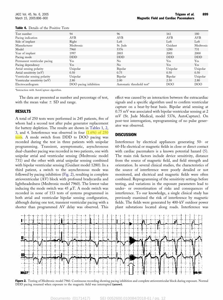
or battery depletion. The results are shown in Tables 1, 2,, and 4. Interference was observed in four (1.6%) of 250ests. A mode switch from DDD to DOO pacing wasecorded during the test in three patients with unipolarrogramming. Transient, asymptomatic, asynchronousual-chamber pacing was recorded in two patients, one withnipolar atrial and ventricular sensing (Medtronic model31) and the other with atrial unipolar sensing combinedith bipolar ventricular sensing (Guidant model 1280). In a
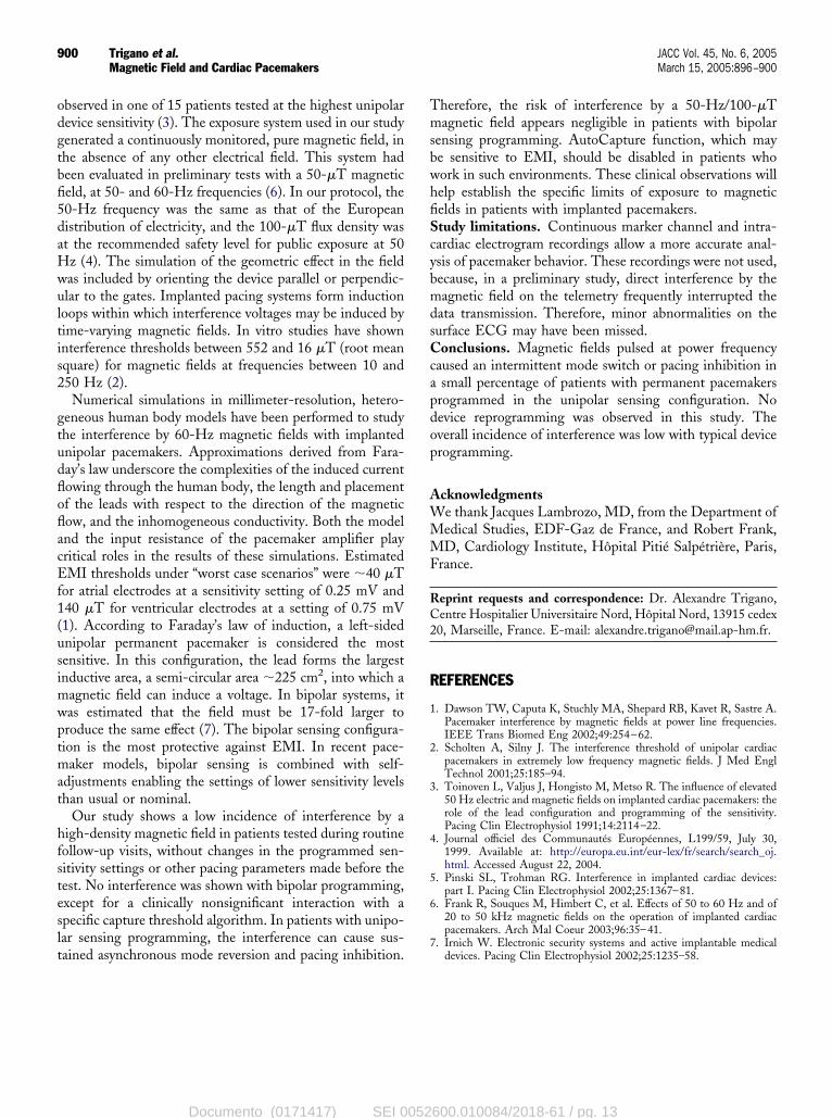
hird patient, a switch to the asynchronous mode wasollowed by pacing inhibition (Fig. 2), resulting in completetrioventricular (AV) block with profound bradycardia andightheadedness (Medtronic model 7960). The lowest valuenducing the mode switch was 45 �T. A mode switch wasecorded in none of 153 tests of systems programmed inoth atrial and ventricular bipolar sensing configuration,lthough during one test, transient ventricular pacing with ahorter than programmed AV delay was observed. This
able 4. Details of the Positive Tests
est number 94acing indication AVBide of implant Rightanufacturer Medtronicodel 7960
ear of implant 1997acing mode DDDermanent ventricular pacing Yesacing dependency Yestrial sensing polarity Unipolartrial sensitivity (mV) 0.50entricular sensing polarity Unipolarentricular sensitivity (mV) 2.80lectrocardiogram DOO pacing inhibition
Interaction with AutoCapture algorithm.
igure 2. Testing of Medtronic model 7960. Continuous recording showing paciDD pacing resumed when exposure to the magnetic field was interrupted (ar
Documento (0171417) SEI 0052
ffect was caused by an interaction between the extracardiacignals and a specific algorithm used to confirm ventricularapture on a beat-by-beat basis. Bipolar atrial sensing at.75 mV was associated with bipolar ventricular sensing at 2V (St. Jude Medical, model 5376, AutoCapture). On
ost-test interrogation, reprogramming of no pulse gener-tor was observed.
ISCUSSION
nterference by electrical appliances generating 50- or0-Hz electrical or magnetic fields in close or direct contactith cardiac pacemakers is a known potential hazard (5).he main risk factors include device sensitivity, distance
rom the source of magnetic field, and field strength andrientation. In several clinical studies, the characteristics ofhe source of interference were poorly detailed or notonitored, and electrical and magnetic fields were often
ombined. Reprogramming of the sensitivity settings beforeesting, and variations in the exposure parameters lead tonder- or overestimation of risks and consequences ofnterference. To our knowledge, a single clinical study hasreviously examined the risk of interference by magneticelds. The fields were generated by 400-kV outdoor powerlant substations located along roads. Interference was
96 161 180AVB AVB AVBLeft Left LeftSt. Jude Guidant Medtronic5376 1280 7312003 2001 2000DDD DDD DDDNo Yes YesNo Yes YesBipolar Unipolar Unipolar0.75 0.50 0.50Bipolar Bipolar Unipolar2.00 2.50 2.80Automatic threshold test* DOO DOO
ng inhibition and complete atrioventricular block during exposure. Normalrow).
600.010084/2018-61 / pg. 12
Administrador
Realce
odgtbfi5daHwultis2
gtudfloflacEf1(usimwptmat
hfsteslt
TmsbwhfiScybmdsCcapdop
AWMMF
RC2
R
1
2
3
4
5
6
900 Trigano et al. JACC Vol. 45, No. 6, 2005Magnetic Field and Cardiac Pacemakers March 15, 2005:896–900
bserved in one of 15 patients tested at the highest unipolarevice sensitivity (3). The exposure system used in our studyenerated a continuously monitored, pure magnetic field, inhe absence of any other electrical field. This system hadeen evaluated in preliminary tests with a 50-�T magneticeld, at 50- and 60-Hz frequencies (6). In our protocol, the0-Hz frequency was the same as that of the Europeanistribution of electricity, and the 100-�T flux density wast the recommended safety level for public exposure at 50z (4). The simulation of the geometric effect in the fieldas included by orienting the device parallel or perpendic-lar to the gates. Implanted pacing systems form inductionoops within which interference voltages may be induced byime-varying magnetic fields. In vitro studies have shownnterference thresholds between 552 and 16 �T (root meanquare) for magnetic fields at frequencies between 10 and50 Hz (2).Numerical simulations in millimeter-resolution, hetero-
eneous human body models have been performed to studyhe interference by 60-Hz magnetic fields with implantednipolar pacemakers. Approximations derived from Fara-ay’s law underscore the complexities of the induced currentowing through the human body, the length and placementf the leads with respect to the direction of the magneticow, and the inhomogeneous conductivity. Both the modelnd the input resistance of the pacemaker amplifier playritical roles in the results of these simulations. EstimatedMI thresholds under “worst case scenarios” were �40 �T
or atrial electrodes at a sensitivity setting of 0.25 mV and40 �T for ventricular electrodes at a setting of 0.75 mV1). According to Faraday’s law of induction, a left-sidednipolar permanent pacemaker is considered the mostensitive. In this configuration, the lead forms the largestnductive area, a semi-circular area �225 cm2, into which a
agnetic field can induce a voltage. In bipolar systems, itas estimated that the field must be 17-fold larger toroduce the same effect (7). The bipolar sensing configura-ion is the most protective against EMI. In recent pace-aker models, bipolar sensing is combined with self-
djustments enabling the settings of lower sensitivity levelshan usual or nominal.
Our study shows a low incidence of interference by aigh-density magnetic field in patients tested during routineollow-up visits, without changes in the programmed sen-itivity settings or other pacing parameters made before theest. No interference was shown with bipolar programming,xcept for a clinically nonsignificant interaction with apecific capture threshold algorithm. In patients with unipo-ar sensing programming, the interference can cause sus-
ained asynchronous mode reversion and pacing inhibition.7
Documento (0171417) SEI 0052
herefore, the risk of interference by a 50-Hz/100-�Tagnetic field appears negligible in patients with bipolar
ensing programming. AutoCapture function, which maye sensitive to EMI, should be disabled in patients whoork in such environments. These clinical observations willelp establish the specific limits of exposure to magneticelds in patients with implanted pacemakers.tudy limitations. Continuous marker channel and intra-ardiac electrogram recordings allow a more accurate anal-sis of pacemaker behavior. These recordings were not used,ecause, in a preliminary study, direct interference by theagnetic field on the telemetry frequently interrupted the
ata transmission. Therefore, minor abnormalities on theurface ECG may have been missed.onclusions. Magnetic fields pulsed at power frequency
aused an intermittent mode switch or pacing inhibition insmall percentage of patients with permanent pacemakers
rogrammed in the unipolar sensing configuration. Noevice reprogramming was observed in this study. Theverall incidence of interference was low with typical devicerogramming.
cknowledgmentse thank Jacques Lambrozo, MD, from the Department ofedical Studies, EDF-Gaz de France, and Robert Frank,D, Cardiology Institute, Hôpital Pitié Salpétrière, Paris,
rance.
eprint requests and correspondence: Dr. Alexandre Trigano,entre Hospitalier Universitaire Nord, Hôpital Nord, 13915 cedex0, Marseille, France. E-mail: [email protected].
EFERENCES
. Dawson TW, Caputa K, Stuchly MA, Shepard RB, Kavet R, Sastre A.Pacemaker interference by magnetic fields at power line frequencies.IEEE Trans Biomed Eng 2002;49:254–62.
. Scholten A, Silny J. The interference threshold of unipolar cardiacpacemakers in extremely low frequency magnetic fields. J Med EnglTechnol 2001;25:185–94.
. Toinoven L, Valjus J, Hongisto M, Metso R. The influence of elevated50 Hz electric and magnetic fields on implanted cardiac pacemakers: therole of the lead configuration and programming of the sensitivity.Pacing Clin Electrophysiol 1991;14:2114–22.
. Journal officiel des Communautés Européennes, L199/59, July 30,1999. Available at: http://europa.eu.int/eur-lex/fr/search/search_oj.html. Accessed August 22, 2004.
. Pinski SL, Trohman RG. Interference in implanted cardiac devices:part I. Pacing Clin Electrophysiol 2002;25:1367–81.
. Frank R, Souques M, Himbert C, et al. Effects of 50 to 60 Hz and of20 to 50 kHz magnetic fields on the operation of implanted cardiacpacemakers. Arch Mal Coeur 2003;96:35–41.
. Irnich W. Electronic security systems and active implantable medicaldevices. Pacing Clin Electrophysiol 2002;25:1235–58.
600.010084/2018-61 / pg. 13
Related Documents


