RISK ASSESSMENT FOR CO2 GEOLOGICAL SEQUESTRATION Yan Zhang Department of Chemical Engineering Carnegie Mellon University Panagiotis Vouzis Department of Chemical Engineering Carnegie Mellon University Nick Sahinidis National Energy Technology Laboratory Department of Chemical Engineering Carnegie Mellon University [email protected]

Welcome message from author
This document is posted to help you gain knowledge. Please leave a comment to let me know what you think about it! Share it to your friends and learn new things together.
Transcript

RISK ASSESSMENT FOR CO2 GEOLOGICAL SEQUESTRATION
Yan Zhang Department of Chemical Engineering
Carnegie Mellon University
Panagiotis Vouzis Department of Chemical Engineering
Carnegie Mellon University
Nick Sahinidis National Energy Technology Laboratory
Department of Chemical Engineering Carnegie Mellon University

OUTLINE
• Introduction to CO2 sequestration • A sequestration simulator • Risk assessment work • GPU parallel computing • Conclusions and future work
2�

INTRODUCTION TO CO2 SEQUESTRATION
• Effect of anthropogenic CO2 on global warming • Carbon mitigation portfolio
– Improved efficiency vehicles – Decarbonization
• renewable, nuclear
– Sequestration
• CO2 sequestration options – Ocean
• large capacity, ecological impact
– Mineral • permanently, energy penalty
– Geological: mature technology • oil/ gas reservoir • deep saline formation • deep coal seam
3�
http://esd.lbl.gov/GCS/gcs-edu-out.html

REVIEW OF SEQUESTRATION MODELING
• Assess the feasibility of CO2 sequestration • Models for
– Pre-injection estimation: capacity evaluation, injection rate, etc – Post-injection prediction: evolution of the sequestration system
4�
Reference Model Modeled problems Formation Trapping mechanism
Bickle et al., 2007 analytical Calibration of model to seismic monitoring data from the Sleipner injection site in the North Sea
homogeneous
Bromhal et., 2005 numerical : PSU-COALCOMP
Storage with enhanced coal-bed methane recovery homogeneous sorption
Doughty and Pruess, 2004
Numerical: TOUGH2
Simulated injection at Frio, TX, test site, evaluated effects of numerical artifacts, choice of characteristic curves
Stochastic three-dimensional heterogeneous
Capillary trapping dissolution
Fiett et al., 2007 Numerical CHEARS
Injection into saline aquifer, assessed impact of varying heterogeneity(sand/shale ratio) on migration
Stochastic three-dimensional heterogeneous
Dissolution, capillary trapping
Gaus et al., 2005 Numerical
Considered impact of geochemical reactions induced by CO2 injection on caprock integrity, based on the Sleipner site
Layered heterogeneity Dissolution, mineralization
*: G.Schnaar and D. C. Digiulio, Vadose Zone Journal, 2009
*

REVIEW OF SEQUESTRATION MODELING (CONT’D)
5�
Reference Model Modeled problems Formation Trapping mechanism
Gheraidi et al., 2005
Numerical: TOUGHREACT
Assessed impact of mineral precipitation and dissolution reactions on migration through caprock; sensitivity analysis for initial mineralogy, kinetic parameters, caprock permeability
Layered heterogeneity Dissolution, mineralization
Izgec et al., 2005 Numerical: STARS
Calibrated model of mineral precipitation and decrease in permeability to data from core experiments; sensitivity analysis for mineralization rate parameters
Homogeneous Dissolution, mineralization
Jessen et al., 2005 Numerical:ECLIPSE300
Injection with enhanced oil recovery operation, analyzed different operation strategies for maximizing storage
Stochastic heterogeneity Dissolution, capillary trapping
Juanes et al., 2006 Numerical:ECLIPSE100
Injection into PUNQ-S3 oil production test-case model; sensitivity analyses for hysteresis
Heterogeneous Dissolution, capillary trapping
Kovscek and Wang, 2005 ECLIPSE300
Geologic sequestration with enhanced oil recovery, evaluation of project design alternatives
Stochastic heterogeneity Dissolution, capillary trapping
Knauss et al.,2005 Numerical: CRUNCH
One-dimensional radial injection into Frio formation, TX; evaluated impact of co-contaminants in injected CO2 stream
Heterogeneous Mineralization, dissolution
*: G.Schnaar and D. C. Digiulio, Vadose Zone Journal, 2009
*

REVIEW OF SEQUESTRATION MODELING (CONT’D)
6�
Reference Model Modeled problems Formation Trapping mechanism
Lagneau et al., 2005
Numerical: Hytec
One- and two-dimensional simulation of evolution of fixed circular zone of high dissolved-CO2 water
Homogeneous Dissolution, mineralization
Leonenko and Keith, 2008
Numerical: CMG IMEX
Assessed efficiency of brine circulation at accelerating dissolution of CO2
Homogeneous Dissolution
LeNeveu, 2008 Semianalytical: CQUESTRA
Semianalytical solutions for assessment of leakage through abandoned well bores and fractures; applied to data from Weyburn basin, Saskathewan
Layered heterogeneity Dissolution, mineralization, capillary trapping
Lindeberg, 1997 Numerical: ECLIPSE100
Injection in formation similar to North Sea; sensitivity analysis for permeability; assessed leakage through penetration; migration under non-flat caprock
Homogeneous, layered heterogeneity cases Dissolution
Nordbotten et al., 2004, 2005a, 2005b, 2006a, 2006b
Analytical Analytical solutions for CO2 leakage through abandoned wells Homogeneous
Oldenburg et al., 2001
Numerical: TOUGH2
Injection into formation based on Rio Vista gas field in California for sequestration and enhanced natural gas recovery
Homogeneous
*: G.Schnaar and D. C. Digiulio, Vadose Zone Journal, 2009
*
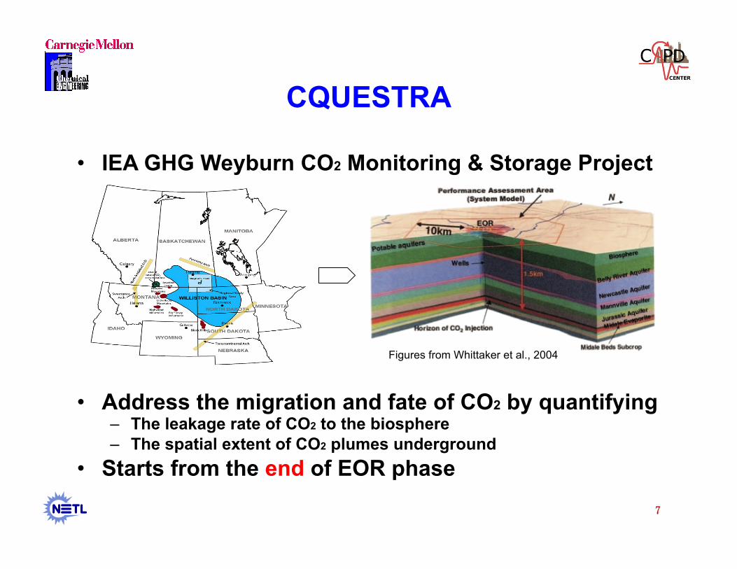
CQUESTRA
• IEA GHG Weyburn CO2 Monitoring & Storage Project
• Address the migration and fate of CO2 by quantifying – The leakage rate of CO2 to the biosphere – The spatial extent of CO2 plumes underground
• Starts from the end of EOR phase
7�
Figures from Whittaker et al., 2004

REVIEW OF RISK ASSESSMENT WORK
• What is the risk associated with sequestration?
• Models are used for quantitative risk analysis to predict CO2 movement in response to varying conditions or scenarios – Walton et al., 2005, used probabilistic risk assessment to
understand and evaluate the performance of CO2 geological sequestration.
– Raza et al., 2009, performed uncertainty analysis using Monte Carlo simulation for capacity estimates and leakage potential for a saline aquifer.
8�

PHYSICAL SYSTEM
9�
>800
Approx. Depth (m) 300
Radius ~0.1m
Aquifer 1 Aquifer 2
Aquifer 4
Aquifer 3
Aquifer 5
Aquifer 6
Aquitard 2
Aquitard 4
Aquitard 3
Aquitard 5 Aquitard 6
Biosphere
Upper Formations
Lower Formations
Oil Reservoir
CO2 Source Pool
Simplified geological structure
Annulus cement
Steel casing
Cement plug
Caprock Low permeability

PROCESS DESCRIPTION
10�
• Viability of a sequestration system:
Leakage
vs .
Sequestration
M: CO2 mass Fi: inflow rate = 0 Fo: outflow rate = leakage-sequestration
Failed seals of wellbore
Open fractures and faults
Dissolution of source pool
Mineralization & geological trapping
Migration of CO2 into surrounding formations
Wellbore
Caprock
Celia et al., 2004

LEAKAGE THROUGH WELLBORE
• Non-penetrating well equation
11�
Wellbore
Caprock
CO2 movement
Fluid pressure
Buoyancy CO2 source pool

MOVEMENT THROUGH CAPROCK
• Equation for drainage in tunnels
12�
Wellbore
Caprock
Fluid pressure
Buoyancy CO2 source pool

DISSOLUTION OF SOURCE POOL
• Dissolution of source pool to the formations below or above the source
13�
CO2 source pool
A layer of stagnant formation fluids
CO2 source pool
A layer of moving formation fluids
Diffusion through a semi-infinite plane
Diffusion through a falling film
Steady state dissolution rate =
Diffusion through a semi-infinite plane
+
Diffusion through a falling film

MIGRATION THROUGH FAILED SEALS
• Migration of CO2 to surrounding formations through failed seals on the way of rising up – Failure times are unpredictable
• If the cement annulus fails first… • If the cement plug fails first…
– Physical model Heat conduction from a thin wire
• Aquifer with advection, dispersion and reaction • Aquitard with diffusion and reaction
Apply solution for temperature profile
Get CO2 concentration in the formation
Obtain steady state flux at the wall of the wellbore
Migration rate = steady state flux * concentration at the wall * thickness 14�
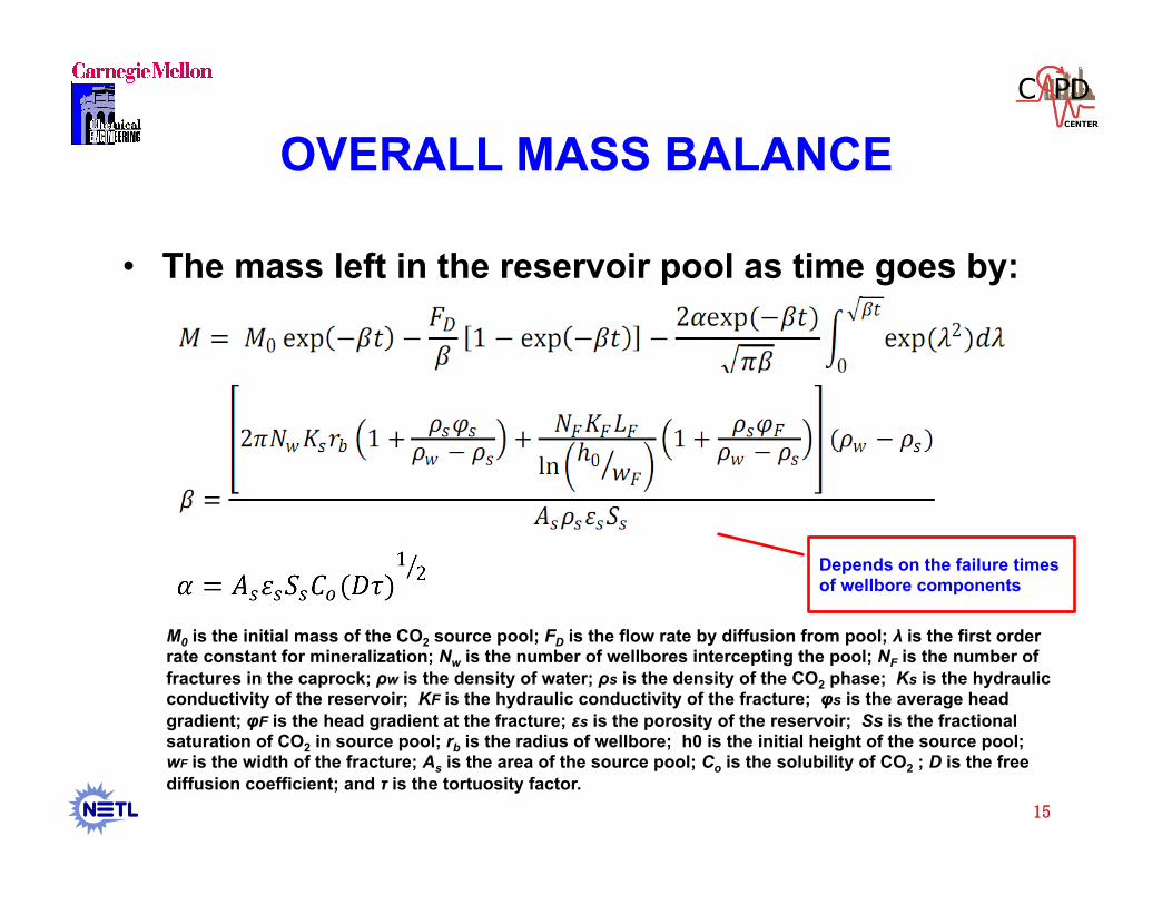
OVERALL MASS BALANCE
• The mass left in the reservoir pool as time goes by:
15�
M0 is the initial mass of the CO2 source pool; FD is the flow rate by diffusion from pool; λ is the first order rate constant for mineralization; Nw is the number of wellbores intercepting the pool; NF is the number of fractures in the caprock; ρw is the density of water; ρs is the density of the CO2 phase; Ks is the hydraulic conductivity of the reservoir; KF is the hydraulic conductivity of the fracture; φs is the average head gradient; φF is the head gradient at the fracture; εs is the porosity of the reservoir; Ss is the fractional saturation of CO2 in source pool; rb is the radius of wellbore; h0 is the initial height of the source pool; wF is the width of the fracture; As is the area of the source pool; Co is the solubility of CO2 ; D is the free diffusion coefficient; and τ is the tortuosity factor.
Depends on the failure times of wellbore components

MODEL PARAMETERS
• Parameters: – Main independent parameters
– Main calculated parameters: formation fluid density, free phase density, viscosity, solubility, etc.
16�
Formation Brine water CO2 phase Wellbore
• Depth • Thickness • Permeability • Porosity • Tortuosity • Mineralization rate • …
• Salinity • Pressure • Surface tension of the free phase • Temperature gradient • Darcy velocity • Capillary pressure in reservoir • Dispersion coefficients • …
• Mass • Composition • Thermo-property • Permeability • Effective saturation • …
• Cement seal failure times • Casing failure times • Permeability of degraded cement • Effective crack diameter of degraded cement • Surface tension • Wellbore radius

RESULTS FOR ONE SET OF PARAMETERS
17�
CO2 mass fractions vs. time CO2 leakage rate (kg/a) vs. time
Sequestered in the formations
Left in the reservoir
Released to the biosphere
Leakage rate through the wellbore
Leakage rate to the surface
400 years
< 5%
Loss rate due to migration
500 years Loss rate due to migration

RISK ASSESSMENT
• Probabilistic risk assessment provides risk distribution due to the uncertainty
18�
Monte Carlo
simulation
Input: Randomly Sampled from probability distribution function of independent parameters
Output: Statistical Analysis

MONTE CARLO SIMULATION
19�
Generated inputs with independent parameters
sample #
x1 x2 x3 x4 x5 … xn
Permeability Porosity Leakage time
Darcy Velocity
Fracture #’s
…
1
2
…
5000
Model Outputs
y1 y2 y3 … ym
Mass left Mass released Leakage rate
1
2
…
5000
Sim
ulat
or

RESULTS FOR MONTE CARLO SIMULATION
20�
Frequency histogram showing fraction released to the biosphere at 5000 years
Freq
uenc
y
Mass fraction released to the biosphere

CONVERGENCE OF MONTE CARLO SIMULATION
21�
0.0419
0.0420
0.0421
0.0422
0.0423
0.0424
0.0425
0.0426
0 5000 10000 15000 20000 25000 30000 35000 40000 45000 50000 M
ass
(%) M
ean
Valu
e
MC Simulations
MassReleased
0.42
0.44
0.46
0.48
0.50
0.52
0.54
0 10000 20000 30000 40000 50000
Mas
s (%
) Mea
n Va
lue
MC Simulations
MassLeft MassLayer
Mean value of mass fractions vs. numbers of simulations

GPU PARALLEL COMPUTING
• Multi-core and many-core
CPU
GPU
22�
http://www.nvidia.com/object/GPU_Computing.html
Lecture Notes, David Kirk/NVIDIA and Wen-mei Hwu, 2006-2008
Dynamic Random Access Memory
CORE CORE
CORE CORE

GPU SPEEDUPS
23�
0
0.1
0.2
0.3
0.4
0.5
0 10000 20000 30000 40000 50000
Tim
e (s
ec)
MC Simulations
GPU Mem Transfer GPU Processing GPU Total Time
0
30
60
90
120
150
0 10000 20000 30000 40000 50000
Tim
e (s
ec)
MC Simulations
hipp 1 t hread hipp 4 threads
Intel Core2 Quad @ 2.83 GHz
0 50
100 150 200 250 300 350
0 10000 20000 30000 40000 50000
Spee
dup
MC Simulations
Speedup hipp 1 threads Speedup hipp 4 threads
Tesla C1060 series GPUs, 240 Processors

CONCLUSIONS AND FUTURE WORK
• Developed a CO2 sequestration simulator – Based mostly on the ideas of the CQUESTRA model
• Performed deterministic simulation and probabilistic risk assessment – Over 90% of the injected CO2 is safely trapped underground after
5000 years in our simulations
• Parallel implementation of Monte Carlo simulation on GPUs – 350 times speedups
• Future work – Conduct extensive scenario analysis – Identify parameters/failure scenarios using derivative-free
optimization algorithms
24�

25�
Related Documents