Qualität Sicherheit Erfahrung Zuverlässigkeit Quality Security Know how Reliability Qualité Sécurité Expérience Confiance Qualität Sicherheit Erfahrung Zuverlässigkeit Quality Security Know how Reliability Qualité Sécurité Expérience Confiance Original SEEGER ® Original SEEGER ® ISO / TS 16949 · DIN ISO 14001 · OHSAS 18001: 1999 KATALOG SEEGER ® -RINGE CATALOGUE SEEGER ® -RINGS CATALOGUE ANNEAUX SEEGER ® SEEGER ® -RINGE · SEEGER ® -RINGS · ANNEAUX SEEGER ® Seeger-Orbis GmbH & Co. OHG Postfach 1460 Wiesbadener Str. 243 – 247 D-61454 Königstein Telefon + 49 - 61 74 - 205 - 0 Telefax + 49 - 61 74 - 205 - 209 Internet http://www.seeger-orbis.de e-mail [email protected] An Associated Spring Company An Associated Spring Company

Welcome message from author
This document is posted to help you gain knowledge. Please leave a comment to let me know what you think about it! Share it to your friends and learn new things together.
Transcript

Qualität Sicherheit Erfahrung
Zuverlässigkeit
Quality Security
Know howReliability
Qualité Sécurité
ExpérienceConfiance
Qualität Sicherheit Erfahrung
Zuverlässigkeit
Quality Security
Know howReliability
Qualité Sécurité
ExpérienceConfiance
Original SEEGER ®Original SEEGER ®
ISO / TS 16949 · DIN ISO 14001 · OHSAS 18001: 1999
K ATA L O G S E E G E R ® - R I N G E
CATALOGUE S E E G E R ® - R I N G S
CATALOGUE ANNEAUX SEEGER ®
SE
EG
ER
®-R
ING
E·
SE
EG
ER
®-R
ING
S·
AN
NEA
UX
SEEG
ER
®
Seeger-Orbis GmbH & Co. OHG
Postfach 1460Wiesbadener Str. 243 – 247D-61454 Königstein
Telefon + 49 - 61 74 - 205 - 0Telefax + 49 - 61 74 - 205 - 209
Internet http://www.seeger-orbis.dee-mail [email protected] An Associated Spring CompanyAn Associated Spring Company
Seeger-Orbis mit Sitz in Königstein/T s.,Deutschland, ist ein Unternehmen derBarnes Group Inc., Bristol, Connecticut, USAund gehört zu dem GeschäftsbereichAssociated Spring, USA. Associated Springist einer der weltweit größten Hersteller vonPräzisionsfedern.Seeger-Orbis entwickelt, produziert und ver-kauft ein umfangreiches Sortiment vonBefestigungselementen, Sicherungsringen,Sprengringen, Stütz- und Paßscheiben.Seeger-Orbis vertreibt die Produkte im Inlandund Ausland über ein flächendeckendes Netzvon V ertragshändlern und beliefert die ge-samte Automobil- und Zulieferindustrie welt-weit. Damit ist gewährleistet, dass weltweitSeeger-Produkte mit Seeger-Qualität undder gewünschten technischen Beratung zurVerfügung stehen. Bitte sprechen Sie schonim Planungstadium unsere technischenBerater an.Wenn Sie tiefer in die Seeger-Befestigungs-technik einsteigen wollen, empfehlen wirIhnen das Seeger-Handbuch anzufordern.
Seeger-Orbis, based in Königstein/T s.,Germany, is a company belonging to theBarnes Group Inc., Bristol, Connecticut,USAand is part of the Associated Springgroup, USA. Associated Spring is one ofthe biggest producers of precisionsprings worldwide.Seeger-Orbis develops, produces andmarkets a comprehensive range of fa-stenings, circlips, retaining rings, sup-porting rings and shims.Seeger-Orbis markets these products na-tionally and internationally through an ex-tensive network of appointed dealers andsupplies all of the automobile industry andits ancillaries worldwide. This guaranteesthat Seeger products with Seeger qualityand the necessary technical support areavailable throughout the world. You mayeven take advantage of our technical sup-port when planning new developments.If you wish to explore Seeger fasteningstechnology further, we advise you to ob-tain our Seeger handbook.
Seeger-Orbis dont le siège se trouve àKönigstein/Ts, Allemagne, est une société dugroupe Barnes Inc., Bristol, Connecticut, USAetfait partie du secteur commercial AssociatedSpring, USA. Associated Spring est l’un des plusgrands fabricants du monde de ressorts de pré-cision.Seeger-Orbis développe, produit et vend unegamme étendue d’éléments de fixation, de ba-gues de sûreté, de circlips, de bagues d’appuiet de rondelles d’ajustage.Seeger-Orbis distribue ces produits enAllemagne et à l’étranger par l’intermédiaired’un réseau global de concessionnaires et four-nit l’ensemble de l’industrie automobile et dessous-traitants dans le monde entier. Ainsi est ga-ranti que, dans le monde entier , les produitsSeeger, ayant la qualité Seeger et le conseiltechnique souhaité soient disponibles partoutdans le monde. Veuillez vous adresser dès l’éta-pe de planification à nos conseillers techniques. Si vous désirez pénétrer plus loin dans la tech-nique de fixation Seeger , nous vous recom-mandons de demander le manuel Seeger.
Seeger-Orbis GmbH & Co. OHG
Postfach 1460D-61454 Königstein (Taunus)
Wiesbadener Straße 243-247D-61462 Königstein (Taunus)
Telefon: +49 -(0)-6174-205-0Telefax: +49 -(0)-6174-205-209E-mail: [email protected]: http://www.seeger-orbis.de
© Seeger-Orbis, Neuauflage 2007
Nachdruck, auch auszugsweise oder inanderen Sprachen, nur mit unsererGenehmigung.
Sämtliche Urheberrechte: Seeger-Orbis GmbH & Co. OHG, D-61642 Königstein (Taunus).
Die Angaben in diesem Katalog wur-den mit größter Sorgfalt auf ihreRichtigkeit hin überprüft. Für eventu-elle fehlerhafte oder unvollständigeAngaben kann keine Haftung über-nommen werden. Die Bezeichnungen „Seeger“ + „Seeger-Ring“ + Original Seeger + Seeger-Logosind gesetzlich geschützt.
8. überarbeitete Auflage
© Seeger-Orbis, new edition 2007
No part of this catalogue may be repro-duced or translated into foreign languagesin any form without express permission.
All copyrights: Seeger-Orbis GmbH & Co. OHG, D-61642 Königstein (Taunus).
Whilst information in this cataloguehas been checked for accuracy , noliability can be accepted by Seegerfor any incorrect or incomplete infor-mation.
The name „Seeger“ + „Seeger-Ring“ +„Original Seeger“ + Seeger-Logo areprotected by copyright.
8th revised edition
© Seeger-Orbis, nouvelle édition 2007
Toute reproduction même partielle ou end’autres langues doit être soumise ànotre autorisation.
Tous droits réservés: Seeger-Orbis GmbH & Co. OHG, D-61642 Königstein (Taunus).
L'exactitude des indications figurantdans ce catalogue a été contrôléeavec le plus grand soin. Nous décli-nons toute responsabilité pour leséventuelles erreurs et lacunes de cesindications. Les termes „Seeger“ + „Seeger-Ring“ +„Original Seeger“ + le logo Seeger sontprotégés par la loi.
8ème édition révisée
SEEGER-ORBIS
Überreicht durch: / Obtained from:Vente par:
1
InhaltsverzeichnisTable of contents
Table des matières
Allgemeine Anmerkungen . . . . . . . . . . . . . . . . . . . . . . . . . . . . .2
1. Qualitätsmanagement . . . . . . . . . . . . . . . . . . . . . . . . . . . . . .3
2. ProduktübersichtStandardsortiment und Spezialteile . . . . . . . . . . . . . . . . . . . . .4Zubehör . . . . . . . . . . . . . . . . . . . . . . . . . . . . . . . . . . . . . . . . .13
3. Begriffe und Bezeichnungen . . . . . . . . . . . . . . . . . . . . . . . .14
4. MaßlistenGruppe 1 Seeger-Ringe Grundtypen . . . . . . . . . . . . . . . . . .18Gruppe 2 Selbstsperrende Seeger-Ringe . . . . . . . . . . . . . . .56Gruppe 3 Radialmontierbare Seeger-Ringe . . . . . . . . . . . . .66Gruppe 4 Seeger-Ringe zum Ausgleich axialen Spiels . . . . .73Gruppe 5 Seeger-Sprengringe . . . . . . . . . . . . . . . . . . . . . . .81Gruppe 6 Paß- und Stützscheiben DIN 988 . . . . . . . . . . . . .94
5. Montagezangen und -geräte . . . . . . . . . . . . . . . . . . . . . . . .109
6. Produktinformation6.1 Qualitätsanforderungen . . . . . . . . . . . . . . . . . . . . . . . . .1 12
6.2 Werkstoffe . . . . . . . . . . . . . . . . . . . . . . . . . . . . . . . . . . .1 136.3 Härteverfahren . . . . . . . . . . . . . . . . . . . . . . . . . . . . . . . .1 166.4 Oberflächen . . . . . . . . . . . . . . . . . . . . . . . . . . . . . . . . . .1 17
7. Berechnung der Seeger-Ring-Verbindung7.1 Tragfähigkeit der Seeger-Ring-Verbindung . . . . . . . . . .1 197.2 Ablösedrehzahl der Seeger-Ringe für Wellen . . . . . . . .1267.3 Axiale Verschiebung . . . . . . . . . . . . . . . . . . . . . . . . . . .127
8. Konstruktive Einzelheiten8.1 Gestaltung der Nut . . . . . . . . . . . . . . . . . . . . . . . . . . . .1288.2 Ausgleich von axialem Spiel . . . . . . . . . . . . . . . . . . . . .1308.3 Radial formschüssig festgelegte Seeger-Ringe . . . . . . .130
9. Montage von Seeger-Sicherungsringen . . . . . . . . . . . . .132
10. TabellenHärteumrechnung . . . . . . . . . . . . . . . . . . . . . . . . . . . . . . . .135
11. Stichwortverzeichnis . . . . . . . . . . . . . . . . . . . . . . . . . . . .138
General comments . . . . . . . . . . . . . . . . . . . . . . . . . . . . . . . . . . .2
1. Quality management . . . . . . . . . . . . . . . . . . . . . . . . . . . . . . .3
2. Product overviewStandard range and special parts . . . . . . . . . . . . . . . . . . . . . . .4Accessoires . . . . . . . . . . . . . . . . . . . . . . . . . . . . . . . . . . . . . .13
3. Definitions and symbols . . . . . . . . . . . . . . . . . . . . . . . . . . .14
4. Data chartsGroup 1 Seeger-Rings-, basic types . . . . . . . . . . . . . . . . . . .18Group 2 Self-locking Seeger-Rings . . . . . . . . . . . . . . . . . . . .56Group 3 Seeger-Rings for radial assembly . . . . . . . . . . . . . .66Group 4 Seeger-Rings for compensating of axial play . . . . . .73Group 5 Seeger circlips . . . . . . . . . . . . . . . . . . . . . . . . . . . .81Group 6 Shim and support washers to DIN 988 . . . . . . . . . .94
5. Assembly pliers and tools . . . . . . . . . . . . . . . . . . . . . . . . .109
6. Product information6.1 Quality requirements . . . . . . . . . . . . . . . . . . . . . . . . . . .1 12
6.2 Materials . . . . . . . . . . . . . . . . . . . . . . . . . . . . . . . . . . . .1 136.3 Hardening processes . . . . . . . . . . . . . . . . . . . . . . . . . . .1 166.4 Surface finishes . . . . . . . . . . . . . . . . . . . . . . . . . . . . . . .1 17
7. Calculation of Seeger-Ring assemblies7.1 Load bearing capacity of a Seeger-Ring assembly . . . .1197.2 Detaching speed of Seeger-Rings for shafts . . . . . . . .1267.3 Axial displacement . . . . . . . . . . . . . . . . . . . . . . . . . . . .127
8. Design details8.1 Design of the groove . . . . . . . . . . . . . . . . . . . . . . . . . .1288.2 Compensating axial play . . . . . . . . . . . . . . . . . . . . . . .1308.3 Positive radial retention of Seeger-Rings . . . . . . . . . . .130
9. Assembly of Seeger retaining rings . . . . . . . . . . . . . . . .132
10. TablesHardness conversion table . . . . . . . . . . . . . . . . . . . . . . . . .135
11. Index . . . . . . . . . . . . . . . . . . . . . . . . . . . . . . . . . . . . . . . . .138
Remarques générales . . . . . . . . . . . . . . . . . . . . . . . . . . . . . . . .2
1. Gestion de la qualité . . . . . . . . . . . . . . . . . . . . . . . . . . . . . . .3
2. Gamme de produitsProgramme standard et pièces spéciales . . . . . . . . . . . . . . . . .4Accessoires . . . . . . . . . . . . . . . . . . . . . . . . . . . . . . . . . . . . . .13
3. Termes techniques et désignations . . . . . . . . . . . . . . . . . .14
4. Tables dimensionnellesGroupe 1 Types standards . . . . . . . . . . . . . . . . . . . . . . . . . . .18Groupe 2 Segments d’arrêt autobloquants . . . . . . . . . . . . . . .56Groupe 3 Segments d’arrêt montage radial . . . . . . . . . . . . . .66Groupe 4 Segments d’arrêt compensation de jeu axial . . . . .73Groupe 5 Anneaux Expansifs . . . . . . . . . . . . . . . . . . . . . . . .81Groupe 6 Rondelles d’appui et d’ajustage DIN 988 . . . . . . . .94
5. Pinces et outils de montage . . . . . . . . . . . . . . . . . . . . . . . .109
6. Information produits6.1 Critères de qualité . . . . . . . . . . . . . . . . . . . . . . . . . . . . .1 126.2 Matériaux utilisés . . . . . . . . . . . . . . . . . . . . . . . . . . . . . .1 13
6.3 Procédés de trempe . . . . . . . . . . . . . . . . . . . . . . . . . . .1 166.4 Traitements de Surface . . . . . . . . . . . . . . . . . . . . . . . . .1 17
7. Calcul d’un montage7.1 Capacité de charge . . . . . . . . . . . . . . . . . . . . . . . . . . .1 197.2 Vitesse de rotation admissible des segments d’arrêt
pour arbres . . . . . . . . . . . . . . . . . . . . . . . . . . . . . . . . . .1267.3 Déplacement axial . . . . . . . . . . . . . . . . . . . . . . . . . . . .127
8. Recommandations de construction8.1 Conception de la gorge . . . . . . . . . . . . . . . . . . . . . . . .1288.2 Compensation du jeu axial . . . . . . . . . . . . . . . . . . . . . .1308.3 Conception avec segment d’arrêt Seeger
fixé radialement . . . . . . . . . . . . . . . . . . . . . . . . . . . . . .130
9. Montage des segments d’arrêt . . . . . . . . . . . . . . . . . . . .132
10. TablesTables d’équivalence des valeurs de dureté de l’acier/millimètres . . . . . . . . . . . . . . . . . . . . . . . . . . . . . . . . . . . . .135
11. Index . . . . . . . . . . . . . . . . . . . . . . . . . . . . . . . . . . . . . . . . .138
2
Allgemeine AnmerkungenGeneral comments
Remarques générales
Seeger-Standardsortiment
Das Standard-Programm entnehmenSie bitte der jeweils gültigen Seeger-Preisliste. Dieses Programm wird lau-fend dem jeweiligen Marktbedarf ange-passt. Für Artikel aus diesem Katalog, dienicht in der jeweils gültigen Seeger-Preisliste enthalten sind, fordern Siebitte ein Angebot an.
Edelstahl, Bronze, diverseOberflächen-Beschichtungen
Standardsortiment siehe jeweils gültigeSeeger-Preisliste. Für andere Artikel fordern Sie bitte einAngebot an.
Spezialteile nachKundenanforderung
Wir entwickeln, berechnen und fertigenSonderteile für den wirtschaftlichenEinsatz, ausgerichtet auf den spezifi-schen Anwendungsfall.
Im Internet
Seeger-KatalogSeeger-Handbuch
http://www.seeger-orbis.de
Seeger Standard ProductRange
The Seeger Standard Programme isidentical to the product range shown inthe Seeger price list.Any catalogue items not included inthe price list are available on request.Our programme is being continuous-ly adapted to meet changing marketrequirements.
Stainless Steel, Bronze, various surface coatings
Standard product range items in the abo-ve materials are shown in the Seegerprice list.Other items are available on request.
Special Items to Customer’s request
We can quote for development and pro-duction of special parts for commercialapplications, tailored to specific require-ments.
On the Internet
Seeger CatalogueSeeger Handbook
http://www.seeger-orbis.de
Gamme standard Seeger
Vous trouverez le programme standarddans le tarif Seeger correspondant envigueur. Ce programme est constam-ment réadapté aux besoins du marchéet complété. Certains articles disparais-sent ou sont rajoutés. Les articles du catalogue ne figurantpas dans le tarif ne peuvent être misen fabrication que pour une quantitééconomique. Veuillez vous faire éta-blir une offre.
Acier inox, bronze, divers re-vêtements de surface
Assortiment standard, voir le tarif Seegercorrespondant en vigueur. Pour les autres articles faites-vous éta-blir une offre.
Pièces spéciales selonles exigences du client
Nous développons, calculons et fabri-quons des pièces spéciales pour l´ap-plication économique, en fonction descas d’utilisations spécifiques.
Sur Internet
Catalogue SeegerManuel Seeger
http://www.seeger-orbis.de
3
Quality Management System (QMS)The QMS at Seeger-Orbis is in accor-dance with the latest national and inter-national customers’ requirements and iscertified according to ISO TS 16949.
The production processes of each groupof products is monitored by the use ofStatistical Process Control (SPC). thestatistical process control is part of a to-tal computer-assisted system (CAQ)which stores all important quality dataand documents the processes.
Regular product and quality audits mo-nitor the processes laid down in theQMS.
The object of the quality policy atSeeger-Orbis is the continuous impro-vement of processes and products, in-volving all our staff, for the benefit of ourcustomers.
Environmental Management System(EMS)Seeger-Orbis has developed an ef fec-tive EMS which is certified to ISO 14001.The aim is to fulfil all the relevant envi-ronmental laws and regulations and totrain staff in environmental protection.
All processing operations are monitoredwith regard to environmental, energyand resource-saving considerations.This applies in particular to recycling ofmaterials and keeping waste, emissi-ons, and water consumption and dis-charges to a minimum. Environmental-ly friendly packaging is also used.
Work & Health Security SystemSeeger-Orbis emphasises on both se-curity and health of its employees, visi-tors as well as the neighbourhood com-munities.To ensure this we evaluate all risks con-cerning work places and processes. Asa result from that we permanently opti-mize our work & health security sy-stems.
Système de gestion de la qualité (SGQ)Le SGQ de Seeger-Orbis correspond auxexigences les plus récentes aussi biennationales qu’internationales selon lesbesoins des clients et est certifié confor-mément à la norme ISO TS 16949.
Les processus de fabrication de chaquegroupe de production sont surveillés parl’emploi du contrôle statistique des pro-cessus (CSP). Le contrôle statistique desprocessus fait partie d’un système d’en-semble assisté par ordinateur (CAO) quigarde en archive toutes les données im-portantes de qualité et documente lesprocessus.
Les processus déterminés par le SGQsont contrôlés par des audits réguliers auniveau des produits et des processus.
Le but de la politique de la qualité estchez Seeger-Orbis une amélioration con-tinuelle des produits et des processusavec la participation de tous les collabo-rateurs et à l’avantage de nos clients.
Système de gestion de l’environnement (SGE)Seeger-Orbis a établi un SGE efficace eta obtenu le certificat ISO 14001. La tâcheconsiste à satisfaire aux lois et prescrip-tions écologiques correspondantes et deformer tous les collaborateurs en écolo-gie.
Tous les déroulements des processussont également vérifiés en fonction desaspects de ménagement de l’environne-ment, de l’économie d’énergie et des res-sources. Ceci vaut en particulier pour lerecyclage des matériaux, la diminution dela quantité de déchets, des émissions, dela consommation d’eau et de la surchar-ge des eaux usées. On pratique aussil’utilisation d’emballages écologiques.
Travail, santé et sécuritéL’une des priorités de S-O est la Santé etla Sécurité de ses employés, des visiteurset des communautés environnantes.Pour en être sur nous évaluons les ris-ques en permanence, à tous les postesde travail et tous les processus de pro-duction. Le résultat est que nous optimi-sons nos systèmes continuellement.
1.Qualität, Umwelt und ArbeitssicherheitQuality, environment and work security
Qualité, environnement et sécurité de travail
Qualitätsmanagement System (QMS)Das QMS von Seeger-Orbis entsprichtden neuesten Forderungen sowohlnach internationalen als auch nationa-len Kundenanforderungen und ist nachISO TS 16949 zertifiziert.
Die Herstellungsprozesse jeder Pro-duktgruppe werden durch den Einsatzder statistischen Prozesslenkung (SPC)überwacht. Die statistische Prozess-lenkung ist Bestandteil eines gesamtencomputerunterstützten System (CAQ),daß alle wichtigen Qualitätsdaten archi-viert und die Prozesse dokumentiert.
Durch regelmäßige Produkt- undProzess-Audits werden die in dem QMSfestgelegten Verfahren überwacht.
Das Ziel der Qualitäts-Politik beiSeeger-Orbis ist die ständige V erbes-serung von Prozessen und Produktenunter Mitwirkung aller Mitarbeiter zumVorteil unserer Kunden.
Umweltmanagement System (UMS)Seeger-Orbis hat ein wirksames UMSaufgebaut und ist zertifiziert nach ISO14001. Aufgabe ist es, die Einhaltungder relevanten Umweltgesetze und-Vorschriften zu erfüllen und alle Mitar-beiter im Umweltschutz zu schulen.
Alle Prozessabläufe werden auch hin-sichtlich umweltgerechter , energiespa-render und ressourcenschonender As-pekte überprüft. Insbesondere gilt diesfür das Recycling der Materialien, dieMinimierung der Abfallmengen, derEmissionen, des W asserverbrauchsund der Abwasserbelastung. Auch derEinsatz umweltgerechter V erpack-kungen wird praktiziert.
Arbeitssicherheits- und Gesundheitsschutz System (AGS)Eine der Prioritäten von Seeger-Orbisist die Sicherheit und Gesundheit seinerMitarbeiter, Besucher und der Gemein-den in der Nachbarschaft.Dies stellen wir sicher, in dem wir Gefähr-dungsbeurteilungen aller Arbeitsplätzeund Prozesse durchführen. Durch die daraus resultierenden Maß-nahmen optimieren wir ständig die Leis-tung des Arbeitssicherheits- und Ge-sundheitsschutz Systems.

4
Bezeichnung / Designation Seegerring / Seeger rings DIN 471/472 Seeger-V-Ringe / Seeger V rings Seeger-K-Ringe / Seeger K ringsDésignation Segments d’arrêts Seeger DIN 471/472 Segments d’arrêt type V Segments d’arrêt type K
für Wellen für Bohrungen für Wellen für Bohrungen für Wellen für Bohrungenfor shafts for bores for shafts for bores for shafts for bores
pour arbres pour alésages pour arbres pour alésages pour arbres pour alésages
A 3 – A1000 J 8 – J 1000 AV 12 – AV 100 JV 12 – JV 100 AK 16 – AK 140 JK 16 – JK 170
Bezeichnung / Designation Seegerringe schwere Ausführung Greifringe KlemmscheibenDésignation Seeger rings heavy-duty Grip rings Reinforced circular self locking rings
Segments d’arrêt renforcés Colliers d’étranglement Anneaux dentelés renforcés KSDIN 471/472
AS 12 – AS 100 JS 20 – JS 100 G 1,5 – G 30 KS 1,5 – KS 10
Bezeichnung / Designation Seeger-Sprengringe / Seeger circlips Sprengringe / circlips DIN 7993 Stützscheiben PaßscheibenDésignation Anneaux expansifs Anneaux expansifs DIN 7993 Support washers Shim washers
für Wellen für Bohrungen für Wellen für Bohrungen Rondelles d’appui Rondelles d’ajustagefor shafts for bores for shafts for bores
pour arbres pour alésages pour arbres pour alésagesSW 4 – SW 460 SB 7 – SB 440 RW 4 – RW 125 RB 7 – RB 125 SS 3 – SS 170 PS 3 – PS170
Bezeichnung / Designation Spezial Teile, Special components, Montagezange / Assembly pliers Ringspender / Ring DispenserDésignation Pièces spéciales Pinces de montage Distributeur et fourchette de pose
nach Kunden-Zeichnung, auf Anfrage für Wellen für Bohrungenmanufactured on request for shafts for boresfabriquées sur demande pour arbres pour alésages
DIN 5254 ZGA DIN 5256 ZGJ
Bezeichnung / Designation Seeger-L-Ringe / Seeger L rings Keil-Ringe / Bevelled rings Seeger-Sprengringe / Seeger circlipsDésignation Segments d’arrêt L Segments chanfreinés Anneaux expansifs
für Wellen für Bohrungen für Bohrungenfor shafts for bores for bores
pour arbres pour alésages pour alésages
AL 16 – AL 100 JL 16 – JL 100 JB 40 – JB 140 SP 30 – SP 400
Bezeichnung / Designation Zackenrringe / Tooth rings Sicherungsscheiben Halbmondringe Désignation Anneaux dentelés Retaining rings Crescent rings
für Wellen für Bohrungen Colliers d’épaulement Croissantsfor shafts for bores DIN 6799
pour arbres pour alésages
ZA 1,5 – ZA 45 ZJ 8,0 – ZJ 50 RA 1,2 – RA 24,0 H 3 – H 55
Maßliste / Data chart10 11 14 15 16 17Table dimensionnelle
Maßliste / Data chart51 52 53 54 61 62Table dimensionnelle
Maßliste / Data chart18 19 21 23Table dimensionnelle
Maßliste / Data chart24 25 32 33Table dimensionnelle
Maßliste / Data chart40 41 45 50Table dimensionnelle
DIN 5417

5
2.
Seeger-Ringe DIN 471/472 A .../J...für Wellen und Bohrungen sind die amvielseitigsten anwendbaren Sicherungs-elemente. Diese Seeger-Ringe sind diegünstigste Lösung bzgl. Dicke und ra-dialer Breite. Sie übertragen großeAxialkräfte von dem andrückenden Ma-schinenteil auf die Nutwand. Die W el-lenringe können auch bei sehr hohenDrehzahlen verwendet werden.
Anwendung: – Maschinenbau, Fahrzeugbau,
Getriebe, Elektrotechnik,Feinwerktechnik, Apparatebau.
Maßliste 10/11, Seite 22 – 41
Seeger-V-Ringe AV.../JV...für Wellen und Bohrungen haben einekleinere radiale Bauhöhe als dieSeeger-Ringe DIN 471/472. Sie habenzur Achse der Welle bzw. des Gehäuseseine zentrisch begrenzte Schulter undsomit eine wesentlich geringere Un-wucht. Seeger-V -Ringe übertragengleichzeitig axiale Kräfte und dienen alsradiale Führung. Sie sind nach demSeeger-Prinzip des gekrümmten Bal-kens gleicher Festigkeit konstruiert. Diehierzu erforderlichen Ausstanzungenbefinden sich jeweils auf der Nutseite.
Anwendung: – in Konstruktionen mit geringen
radialen Bauhöhen,– zur Festlegung von Nadellagern,
Dichtungen,– Einsatz auch aus optischen
Erwägungen.
Maßliste 14/15, Seite 42 – 45
Seeger-Rings to DIN 471/472 A.../J...for shafts and bores are the most uni-versally applicable retaining systems.These Seeger rings are the most favor-able solution as regards thickness andradial width. They transfer large axialforces from the located machine com-ponent onto the groove wall. The exter-nal rings can also be used for very highspeeds.
Applications: – Mechanical engineering, automotive
engineering, gear systems, electricalengineering, precision mechanicsand apparatus engineering.
Data chart 10/11, Pages 22 – 41
Seeger-V-Rings AV.../JV...for shafts and bores requiring a smallerradial mounting height than the Seegerrings to DIN 471/472. They have a con-centric shoulder with respect to the axisof the shaft or housing and thus sub-stantially less imbalance. Seeger Vrings simultaneously transmit axial for-ces and serve as radial guides. They aredesigned in accordance with the Seegerprinciple of the curved beam of equalstrength. The required recesses areeach located on the groove side.
Applications: – in designs with small radial moun-
ting heights,– for securing needle bearings and
seals,– also for use based on optical consi-
derations.
Data chart 14/15, Pages 42 – 45
Segments d’arrêt Seeger, DIN 471/472A.../J...Pour arbres et alésages. Ce sont lessegments d’arrêt universels. Ces seg-ments sont la solution la plus intéres-sante sur le plan de l’épaisseur et de lalargeur radiale. Ils sont capables detransmettre des ef forts axiaux élevésentre l’élément de machine exerçant lapression et la paroi de la gorge et peu-vent être utilisés sur des arbres tournantà vitesse élevée
Applications: – Construction mécanique, construc-
tion automobile, engrenages, électro-technique, mécanique de précision.électrotechnique, construction d‘ap-pareils.
Table dimensionnelle 10/11, pages 22–41
Segments d’arrêt Seeger type AV.../JV...Pour arbres et alésages. Ces segmentsprésentent une hauteur radiale de mon-tage inférieure à celle des segmentsSeeger DIN 471/472. Ils forment en ou-tre un épaulement concentrique à l’axede l’arbre ou de l’alésage, ce qui réduitconsidérablement leur balourd. Lessegments d’arrêt type V sont de ce faiten mesure de transmettre des ef fortsaxiaux et en même temps, de servird‘épaulement-guide radial. Leur con-ception est basée sur le principe Seegerde la poutre fléchie d’égale résistance.Les découpes nécessaires sont situéesdu côté du fond de gorge.
Applications:– Constructions à faible hauteur
radiale de montage,– Fixation de roulements à aiguilles,
joints,– Egalement pour des raisons
esthétiques.
Table dimensionnelle 14/15, pages 42–45
ProduktübersichtProduct overview
Gamme de produits
6
2.
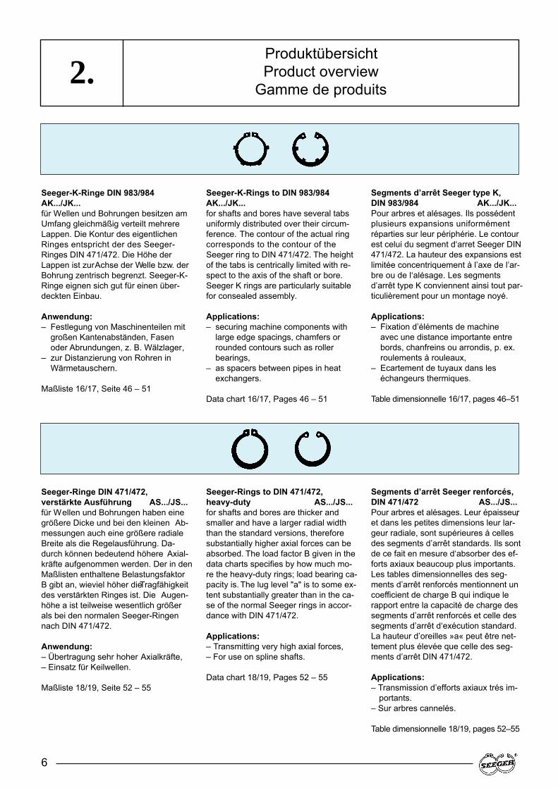
Seeger-K-Ringe DIN 983/984AK.../JK...für Wellen und Bohrungen besitzen amUmfang gleichmäßig verteilt mehrereLappen. Die Kontur des eigentlichenRinges entspricht der des Seeger-Ringes DIN 471/472. Die Höhe derLappen ist zur Achse der Welle bzw. derBohrung zentrisch begrenzt. Seeger-K-Ringe eignen sich gut für einen über-deckten Einbau.
Anwendung:– Festlegung von Maschinenteilen mit
großen Kantenabständen, Fasenoder Abrundungen, z. B. Wälzlager,
– zur Distanzierung von Rohren inWärmetauschern.
Maßliste 16/17, Seite 46 – 51
Seeger-Ringe DIN 471/472, verstärkte Ausführung AS.../JS...für Wellen und Bohrungen haben einegrößere Dicke und bei den kleinen Ab-messungen auch eine größere radialeBreite als die Regelausführung. Da-durch können bedeutend höhere Axial-kräfte aufgenommen werden. Der in denMaßlisten enthaltene BelastungsfaktorB gibt an, wieviel höher die Tragfähigkeitdes verstärkten Ringes ist. Die Augen-höhe a ist teilweise wesentlich größerals bei den normalen Seeger-Ringennach DIN 471/472.
Anwendung:– Übertragung sehr hoher Axialkräfte,– Einsatz für Keilwellen.
Maßliste 18/19, Seite 52 – 55
Seeger-K-Rings to DIN 983/984AK.../JK...for shafts and bores have several tabsuniformly distributed over their circum-ference. The contour of the actual ringcorresponds to the contour of theSeeger ring to DIN 471/472. The heightof the tabs is centrically limited with re-spect to the axis of the shaft or bore.Seeger K rings are particularly suitablefor consealed assembly.
Applications:– securing machine components with
large edge spacings, chamfers orrounded contours such as rollerbearings,
– as spacers between pipes in heatexchangers.
Data chart 16/17, Pages 46 – 51
Seeger-Rings to DIN 471/472, heavy-duty AS.../JS...for shafts and bores are thicker andsmaller and have a larger radial widththan the standard versions, thereforesubstantially higher axial forces can beabsorbed. The load factor B given in thedata charts specifies by how much mo-re the heavy-duty rings; load bearing ca-pacity is. The lug level "a" is to some ex-tent substantially greater than in the ca-se of the normal Seeger rings in accor-dance with DIN 471/472.
Applications:– Transmitting very high axial forces,– For use on spline shafts.
Data chart 18/19, Pages 52 – 55
Segments d’arrêt Seeger type K,DIN 983/984 AK.../JK...Pour arbres et alésages. Ils possédentplusieurs expansions uniformémentréparties sur leur périphérie. Le contourest celui du segment d‘arret Seeger DIN471/472. La hauteur des expansions estlimitée concentriquement à l’axe de l’ar-bre ou de l‘alésage. Les segmentsd’arrêt type K conviennent ainsi tout par-ticulièrement pour un montage noyé.
Applications:– Fixation d’éléments de machine
avec une distance importante entrebords, chanfreins ou arrondis, p. ex.roulements à rouleaux,
– Ecartement de tuyaux dans leséchangeurs thermiques.
Table dimensionnelle 16/17, pages 46–51
Segments d’arrêt Seeger renforcés,DIN 471/472 AS.../JS...Pour arbres et alésages. Leur épaisseur,et dans les petites dimensions leur lar-geur radiale, sont supérieures à cellesdes segments d’arrêt standards. Ils sontde ce fait en mesure d‘absorber des ef-forts axiaux beaucoup plus importants.Les tables dimensionnelles des seg-ments d’arrêt renforcés mentionnent uncoefficient de charge B qui indique lerapport entre la capacité de charge dessegments d’arrêt renforcés et celle dessegments d’arrêt d‘exécution standard.La hauteur d’oreilles »a« peut être net-tement plus élevée que celle des seg-ments d’arrêt DIN 471/472.
Applications:– Transmission d’efforts axiaux trés im-
portants.– Sur arbres cannelés.
Table dimensionnelle 18/19, pages 52–55
ProduktübersichtProduct overview
Gamme de produits
7
2.
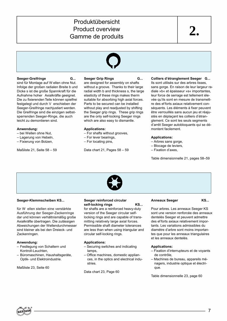
Seeger-Greifringe G...sind für Montage auf W ellen ohne Nut.Infolge der großen radialen Breite b undDicke s ist die große Spannkraft für dieAufnahme hoher Axialkräfte geeignet.Die zu fixierenden Teile können spielfreifestgelegt und durch V erschieben derSeeger-Greifringe nachjustiert werden.Die Greifringe sind die einzigen selbst-sperrenden Seeger-Ringe, die auchleicht zu demontieren sind.
Anwendung:– bei Wellen ohne Nut,– Lagerung von Hebeln,– Fixierung von Bolzen,
Maßliste 21, Seite 58 – 59
Seeger-Klemmscheiben KS...
für W ellen stellen eine verstärkteAusführung der Seeger-Zackenringedar und können verhältnismäßig großeAxialkräfte übertragen. Die zulässigenAbweichungen der Wellendurchmessersind kleiner als bei den Dreieck- undZackenringen.
Anwendung:– Festlegung von Schaltern und
Kontroll-Leuchten,– Büromaschinen, Haushaltsgeräte,
Optik- und Elektroindustrie.
Maßliste 23, Seite 60
Seeger Grip Rings G...are designed for assembly on shaftswithout a groove. Thanks to their largeradial width b and thickness s, the largeelasticity of these rings makes thermsuitable for absorbing high axial forces.Parts to be secured can be installedwithout play and readjusted by shiftingthe Seeger grip rings. These grip ringsare the only self-locking Seeger ringswhich are also easy to dismantle.
Applications:– For shafts without grooves,– For lever bearings,– For locating pins,
Data chart 21, Pages 58 – 59
Seeger reinforced circular self-locking rings KS...for shafts are a reinforced heavy-dutyversion of the Seeger circular self-locking rings and are capable of trans-mitting relatively large axial forces.Permissible shaft diameter tolerancesare less than when using triangular andcircular self-locking rings.
Applications:– Securing switches and indicating
lamps,– Office machines, domestic applian-
ces, in the optics and electrical indu-stries.
Data chart 23, Page 60
Colliers d’étranglement Seeger G...Ils sont utilisés sur des arbres lisses,sans gorge. En raison de leur largeur ra-diale »b« et épaisseur »s« importantes,leur force de serrage est tellement éle-vée qu’ils sont en mesure de transmett-re des ef forts axiaux relativement con-séquents. Les éléments à fixer peuventêtre verrouillés sans aucun jeu et réaju-stés en déplaçant les colliers d’étran-glement. Ce sont les seuls segmentsd’arrêt Seeger autobloquants qui se dé-montent facilement.
Applications:– Arbres sans gorge,– Blocage de leviers,– Fixation d’axes,
Table dimensionnelle 21, pages 58–59
Anneaux Seeger KS...
Pour arbres. Les anneaux Seeger KSsont une version renforcée des anneauxdentelés Seeger et peuvent admettredes ef forts axiaux relativement impor-tants. Les variations admissibles dudiamètre d’arbre sont moins importan-tes que pour les anneaux triangulaireset les anneaux dentelés.
Applications:– Fixation d’interrupteurs et de voyants
de contrôle,– Machines de bureau, appareils mé-
nagers, industrie optique et électri-que.
Table dimensionnelle 23, page 60
ProduktübersichtProduct overview
Gamme de produits
8
2.
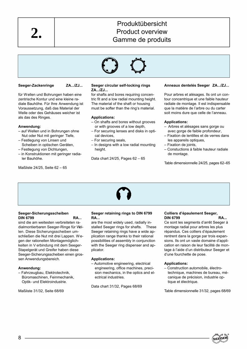
Seeger-Zackenringe ZA.../ZJ...
für Wellen und Bohrungen haben einezentrische Kontur und eine kleine ra-diale Bauhöhe. Für Ihre Anwendung istVoraussetzung, daß das Material derWelle oder des Gehäuses weicher istals das des Ringes.
Anwendung:– auf Wellen und in Bohrungen ohne
Nut oder Nut mit geringer Tiefe,– Festlegung von Linsen und
Scheiben in optischen Geräten,– Festlegung von Dichtungen,– in Konstruktionen mit geringer radia-
ler Bauhöhe.
Maßliste 24/25, Seite 62 – 65
Seeger-Sicherungsscheiben DIN 6799 RA...sind die am weitesten verbreiteten ra-dialmontierbaren Seeger-Ringe für Wel-len. Diese Sicherungsscheiben um-schließen die Nut mit drei Lappen. We-gen der rationellen Montagemöglich-keiten in V erbindung mit dem Seeger-Stapelgerät und Greifer haben dieseSeeger-Sicherungsscheiben einen gros-sen Anwendungsbereich.
Anwendung:– Fahrzeugbau, Elektrotechnik,
Büromaschinen, Feinmechanik,Optik- und Elektroindustrie.
Maßliste 31/32, Seite 68/69
Seeger circular self-locking ringsZA.../ZJ...for shafts and bores requiring concen-tric fit and a low radial mounting height.The material of the shaft or housingmust be softer than the ring‘s material.
Applications:– On shafts and bores without grooves
or with grooves of a low depth,– For securing lenses and disks in opti-
cal devices,– For securing seals,– In designs with a low radial mounting
height.
Data chart 24/25, Pages 62 – 65
Seeger retaining rings to DIN 6799RA...are the most widely used, radially in-stalled Seeger rings for shafts. TheseSeeger retaining rings have a wide ap-plication range thanks to their rationalpossibilities of assembly in conjunctionwith the Seeger ring dispenser and ap-plicator.
Applications:– Automotive engineering, electrical
engineering, office machines, preci-sion mechanics, in the optics and el-ectrical industries.
Data chart 31/32, Pages 68/69
Anneaux dentelés Seeger ZA.../ZJ...
Pour arbres et alésages. Ils ont un con-tour concentrique et une faible hauteurradiale de montage. Il est indispensableque la matière de l’arbre ou du cartersoit moins dure que celle de l’anneau.
Applications:– Arbres et alésages sans gorge ou
avec gorge de faible profondeur,– Fixation de lentilles et de verres dans
les appareils optiques,– Fixation de joints,– Constuctions à faible hauteur radiale
de montage.
Table dimensionnelle 24/25, pages 62–65
Colliers d’épaulement Seeger, DIN 6799 RA...Ce sont les segments d’arrêt Seeger àmontage radial pour arbres les plusrépandus. Ces colliers d’épaulementrentrent dans la gorge par trois expan-sions. Ils ont un vaste domaine d’appli-cation en raison de leur facilité de mon-tage à l’aide d’un distributeur Seeger etd’une fourchette de pose.
Applications:– Construction automobile, électro-
technique, machines de bureau, mé-canique de précision, industrie op-tique et électrique.
Table dimensionnelle 31/32, pages 68/69
ProduktübersichtProduct overview
Gamme de produits

9
2.
Seeger-Halbmondringe H...für Wellen sind die einzigen radial mon-tierbaren Sicherungsringe, die nach demSeeger-Prinzip des gekrümmten Bal-kens gleicher Festigkeit aufgebaut sind.Aufgrund der hieraus folgenden hohenElastizität ist der Umschlingungswinkelverhältnismäßig groß. Die Schulterhöheist nicht so hoch wie bei der AusführungDIN 6799. Die Halbmondringe werdenfür Wellendurchmesser bis 55 mm ge-fertigt.
Anwendung:– im Gelenkwellenbau für innere
Fixierung der Nadelbüchsen,– in Laschenketten.
Maßliste 33, Seite 70/71
Seeger-L-Ringe AL.../JL...
für Wellen und Bohrungen entsprechenin ihrer Form den Seeger-K-Ringen. Siesind jedoch tellerfederartig geprägt undso in der Lage, Axialspiel geringen Aus-maßes federnd auszugleichen.
Anwendung:– Ausgleich von Axialspiel bei Wellen
und Bohrungen,– Andruck von Nilos-Ringen an
Wälzlagern,– Festlegung der Endscheiben von
Lamellenkupplungen.
Maßliste 40/41, Seite 74 – 77
Seeger crescent rings H...for shafts are the only radially installedlocking rings designed in accordancewith the Seeger principle of the curvedbeam of equal strength. The envelop-ment angle is relatively large due to theconsequently resulting high elasticity .The shoulder height of these rings is notas large as in the STand DIN 6799 ver-sions. These crescent rings are manu-factured for shaft diameters up to 55 mm.
Applications:– In universal-joint propeller shaft con-
structions for internally securing theneedle bushes,
– in flat link articulated chains.
Data chart 33, Pages 70/71
Seeger-L-Rings AL../JL...
for shafts and bores correspond in sha-pe to the Seeger K rings. However, theyare stamped to function as tab springsand are thus capable of compensatingfor slight axial play by spring action.
Applications:– Compensating for axial play of shafts
and bores,– Pressing Nilos rings onto roller bea-
rings,– Securing the end plates of multiple
disc clutches.
Data chart 40/41, Pages 74 – 77
Croissants Seeger H...Pour arbres. Ce sont les seuls seg-ments d’arrêt à montage radial conçusselon le principe Seeger de la poutrefléchie d’égale résistance. En raison del’élastictité élevée qui en résulte, l’angled’enserrement est relativement grand.Leur hauteur d’épaulement n’est pasaussi importante que celle des types STet DIN 6799. Les croissants sont fabri-qués pour des diamètres d’arbre jusqu’à 55 mm.
Applications:– Fixation d’arbres articulés,– Axes de chaines mécaniques,– Fixation de douilles à aiguilles.
Table dimensionnelle 33, pages 70/71
Segments d’arrêt Seeger type LAL.../JL...Pour arbres et alésages. La forme deces segments correspond à celle dessegments d’arrêt Seeger type K. Ils onttoutefois des expansions du type ron-delles Belleville qui leur permettent decompenser élastiquement un jeu axialde faible importance.
Applications:– Compensation du jeu axial d’arbres
et d’alésages,– Application d‘anneaux Nilos contre
des roulements à rouleaux,– Fixation des disques terminaux
d‘embrayages à disques.
Table dimensionnelle 40/41, pages 74–77
ProduktübersichtProduct overview
Gamme de produits

Seeger bevelled rings JB...
for bores have the same characteristicsas the Seeger rings to DIN 472, but of-fer the additional advantage of rigidlycompensating axial tolerances. ThisSeeger ring acts like a wedge betweenthe slanted load side of the groove andthe machine part to be secured. By me-ans of its spring force, the ring springsinto the groove to such an extent as tocompensate for any play.
Applications:– Compensating axial play in bores,– Gear systems and wheel bearings,– Automotive engineering,– Mechanical engineering.
Data chart 45, Pages 78/79
Seeger circlips DIN 5417 SP...
for shafts serve to secure roller bearingsin accordance with DIN 616 in whoseouter race a groove has been cut.
Applications:– Roller bearing housings can be drilled
through smoothly,– The housing has a short axial moun-
ting length,– Roller bearings in accordance with
DIN 616.
Data chart 50, Pages 82 – 85
10
2.
Seeger-Keilringe JB...
für Bohrungen besitzen die gleichenEigenschaften wie die Seeger-Ringenach DIN 472, bieten jedoch als zu-sätzlichen V orteil die Möglichkeit desstarren Ausgleichs von axialen Toleran-zen. Dieser Seeger-Ring wirkt wie einKeil zwischen der geschrägten Last-seite der Nut und dem festzulegendenMaschinenteil. Aufgrund seiner Feder-kraft springt der Ring so tief in die Nutein, bis das vorhandene Spiel ausgegli-chen ist.
Anwendung:– Ausgleich von Axialspiel in
Bohrungen,– Getriebe, Radlagerung,– Fahrzeugbau,– Maschinenbau.
Maßliste 45, Seite 78/79
Seeger-Sprengringe DIN 5417 SP...
für W ellen dienen zur Festlegung vonWälzlagern nach DIN 616, in derenAußenring eine Nut eingestochen ist.
Anwendung:– Gehäuse für Wälzlager kann glatt
durchgebohrt werden,– Gehäuse hat kurze axiale Baulänge,– Wälzlager nach DIN 616.
Maßliste 50, Seite 82 – 85
Segments d’arrêt chanfreinés SeegerJB...Pour alésages. Ils ont les mêmes pro-priétés que les segments d’arrêt SeegerDIN 472, mais ont l’avantage de per-mettre une compensation rigide destolérances axiales. Cet anneau Seegerfait fonction de clavette entre le côtéchanfreiné de la gorge et l’élément demachine à fixer. Grâce à son élasticité,l’anneau pénètre aussi profondémentque nécessaire dans la gorge pour com-penser le jeu.
Applications:– Compensation du jeu axial d’alésages,– Engrenages, logements de roues,– Construction automobile.
Table dimensionnelle 45, pages 78/79
Anneaux expansifs Seeger, DIN 5417SP...Ils servent à fixer les roulements à rou-leaux DIN 616 dont la cage extérieurecomporte une gorge.
Applications:– Logements de roulements à rou-
leaux pouvant être alésés lisses,– Logements ayant une faible longueur
axiale de montage,– Roulements à rouleaux selon
DIN 616.
Table dimensionnelle 50, pages 82 – 85
ProduktübersichtProduct overview
Gamme de produits

11
2.
Seeger-Sprengringe SW.../SB...
für Wellen und Bohrungen sind, mit Aus-nahme der Runddrahtringe, die Siche-rungselemente mit der kleinsten radia-len Breite. Die Ablösedrehzahlen derWellenringe SW sind bei den größerenAbmessungen nur gering. Bei dem Ein-satz der Sprengringe SW/SB für dieÜbertragung größerer Axialkräfte ist vonder Möglichkeit der Wahl tieferer NutenGebrauch zu machen.
Anwendung:– Getriebebau,– Festlegung von Nadellagern,
Nadelkäfige undDichtungselementen,
– Einsatz als Distanzelemente.
Maßliste 51/52, Seite 86 – 91
Seeger-Sprengringe DIN 7993RW.../RB...für Wellen und Bohrungen werden auspatentgehärteten Drähten mit rundemQuerschnitt gefertigt. Ihr Einsatz erfolgtvorzugsweise in halbrunden Nuten inVerbindung mit einer viertelkreisförmi-gen Überdeckung des andrückendenMaschinenteiles.
Anwendung:– Festlegung von Kolbenbolzen
(Sonderformen),– Getriebe,– Fahrzeugbau,– als Montagehilfselemente,– Beschlagindustrie.
Maßliste 53/54, Seite 92 – 93
Seeger snap rings SW.../SB...
for shafts and bores are, with the ex-ception of the circular wire rings, the re-taining systems with the smallest radialwidth. In the larger dimensions, the loo-sening speeds of the SW shaft rings arelow. When using SW/SB circlips for thetransmission of larger axial forces, usemust be made of the possibility of choo-sing deeper grooves.
Applications:– Gear system construction,– Securing needle bearings, needle
cages and sealing elements,– Used as spacer elements.
Data chart 51/52, Pages 86 – 91
Seeger snap rings DIN 7993RW.../RB...for shafts and bores are manufacturedfor cold-worked wires with a round crosssection. They are predominantly used insemicircular grooves in conjunction withquarter-circle coverage of the locatedmachine component.
Applications:– Securing gudgeon pins (special
shapes),– Gear systems,– Automotive engineering,– As auxiliary installation elements,– In the fittings industry.
Data chart 53/54, Pages 92 – 93
Anneaux expansifs SeegerSW.../SB...Pour arbres et alésages. De tous les ty-pes d’anneaux de sécurité, à l’exceptiondes joncs d’arrêt, ce sont ceux qui pos-sèdent la plus petite largeur radiale.Dans les dimensions assez importan-tes, les vitesses de rotation admissiblespour les anneaux expansifs SW sont fai-bles. En cas d’utilisation d’anneaux ex-pansifs SW/SB pour des ef forts axiauximportants, il est préférable d’opter pourune gorge plus profonde.
Applications:– Fabrication d’engrenages– Fixation de roulements à aiguilles,
de cages de paliers à aiguilles etd’éléments d’étanchéité,
– Comme éléments d’écartement
Table dimensionnelle 51/52, pages 86–91
Joncs d’arrêt Seeger, DIN 7993RW.../RB...Pour arbres et alésages. Ils sont fabri-qués à partir de fils calibrés de sectionronde. Ils sont utilisés de préférencedans des gorges demi-rondes, en liai-son avec un recouvrement en quart decercle de l’élément de machine qui exer-ce la pression.
Applications:– Fixation d’axes de pistons (Formes
spéciales),– Engrenages,– Construction automobile,– Accessoire de montage,– Ferronnerie, serrurerie.
Table dimensionnelle 53/54, pages 92–93
ProduktübersichtProduct overview
Gamme de produits

12
2.
Seeger-Stützscheiben DIN 988 SS...
werden aus Federstahl gefertigt und ha-ben eine Härte von HRC 44–49. Diegrößeren Abmessungen haben ge-schliffene Seitenflächen.
Anwendung:– zwischen Maschinenteilen mit
großen Rundungen, Fasen oderKantenabständen und Seeger-Ringen, zur Schaffung einer scharf-kantigen Anlage, z. B. beiWälzlagern.
Maßliste 61, Seite 96 – 97
Seeger-Paßscheiben DIN 988 PS...
Das Axialspiel, das sich aus Fertigungs-toleranzen ergibt, kann stufenweisedurch Paßscheiben verschiedener Dik-ken starr reduziert werden. Jede erfor-derliche Kombination in Dickenstufungvon 0,1 mm ist zusammenstellbar . DiePaßscheiben werden über DIN 988 hin-aus auch in den Dicken 0,15 mm und0,25 mm hergestellt; die Dicken 1,1 bis1,9 mm werden nur auf Anfrage gefer-tigt.
Anwendung:– Ausgleich von Axialspiel,– Maschinenbau,– Fahrzeugbau,– Getriebe.
Maßliste 62, Seite 98 – 108
Seeger support washers to DIN 988SS...are manufactured from spring steel andhave a hardness of HRC 44–49. The lar-ger dimensions have ground side faces.
Applications:– between machine components with
larger rounded faces, chamfers oredge spacings and Seeger rings orfor creating a sharp-edged face sur-face, e. g. on roller bearings.
Data chart 61, Pages 96 – 97
Seeger shim washers to DIN 988PS...Axial play resulting from manufacturingtolerances can be rigidly reduced insteps by using various thicknesses ofshim washers. All required combinati-ons in staggered steps of 0,1 mm canbe used. Over and above DIN 988, the-se shim washers are also manufacturedin thicknesses of 0.15 mm and 0.25 mm;the thicknesses from 1.1 to 1.9 mm aremanufactured on request only.
Applications:– Compensating for axial play,– Mechanical engineering,– Automotive engineering,– Gear systems
Data chart 62, Pages 98 – 108
Rondelles d’appui Seeger, DIN 988SS...Elles sont fabriquées en acier à ressortet ont une dureté 44–49 HRC. Dans lesgrandes dimensions, les faces latéralessont rectifiées.
Applications:– Entre des éléments de machine pré-
sentant des arrondis importants, deschanfreins ou des distances entrebords et des segments d’arrêtSeeger, pour obtenir un appui àangles vifs, comme par exemplepour les roulements à rouleaux.
Table dimensionnelle 61, pages 96 – 97
Rondelles d’ajustage Seeger, DIN 988PS....Grâce aux rondelles d’ajustage d’épais-seurs variables, il est possible de rédui-re progressivement le jeu axial résultantdes tolérances de fabrication. Les ron-delles, dont l’épaisseur varie par degrésde 0,1 mm, peuvent être combinées àvolonté. Les rondelles d’ajustage normeDIN 988 sont également fabriquéesdans des épaisseurs de 0,15 et 0,25 mm.Les rondelles de 1,1 à 1,9 mm d’épais-seur ne sont fabriquées que sur de-mande.
Applications:– Compensation du jeu axial,– Construction mécanique,– Construction automobile,– Engrenages.
Table dimensionnelle 62, pages 98 – 108
ProduktübersichtProduct overview
Gamme de produits
13
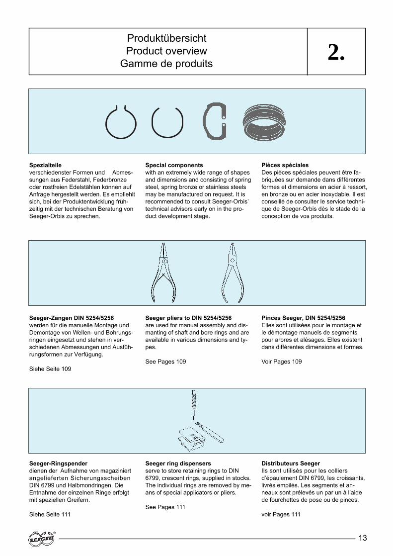
Spezialteileverschiedenster Formen und Abmes-sungen aus Federstahl, Federbronzeoder rostfreien Edelstählen können aufAnfrage hergestellt werden. Es empfiehltsich, bei der Produktentwicklung früh-zeitig mit der technischen Beratung vonSeeger-Orbis zu sprechen.
Seeger-Zangen DIN 5254/5256werden für die manuelle Montage undDemontage von Wellen- und Bohrungs-ringen eingesetzt und stehen in ver-schiedenen Abmessungen und Ausfüh-rungsformen zur Verfügung.
Siehe Seite 109
Seeger-Ringspenderdienen der Aufnahme von magaziniertangelieferten SicherungsscheibenDIN 6799 und Halbmondringen. DieEntnahme der einzelnen Ringe erfolgtmit speziellen Greifern.
Siehe Seite 111
Special componentswith an extremely wide range of shapesand dimensions and consisting of springsteel, spring bronze or stainless steelsmay be manufactured on request. It isrecommended to consult Seeger-Orbis’technical advisors early on in the pro-duct development stage.
Seeger pliers to DIN 5254/5256are used for manual assembly and dis-manting of shaft and bore rings and areavailable in various dimensions and ty-pes.
See Pages 109
Seeger ring dispensersserve to store retaining rings to DIN6799, crescent rings, supplied in stocks.The individual rings are removed by me-ans of special applicators or pliers.
See Pages 111
Pièces spécialesDes pièces spéciales peuvent être fa-briquées sur demande dans différentesformes et dimensions en acier à ressort,en bronze ou en acier inoxydable. Il estconseillé de consulter le service techni-que de Seeger-Orbis dès le stade de laconception de vos produits.
Pinces Seeger, DIN 5254/5256Elles sont utilisées pour le montage etle démontage manuels de segmentspour arbres et alésages. Elles existentdans différentes dimensions et formes.
Voir Pages 109
Distributeurs SeegerIls sont utilisés pour les colliersd’épaulement DIN 6799, les croissants,livrés empilés. Les segments et an-neaux sont prélevés un par un à l’aidede fourchettes de pose ou de pinces.
voir Pages 111
2.ProduktübersichtProduct overview
Gamme de produits
14
3.Seeger-Ring:Sicherungsring, dessen radiale Breitesich nach den freien Enden verklei-nert, entsprechend dem Gesetz desgekrümmten Balkens gleicher Festig-keit, so daß er sich im gespanntenZustand rund verformt.
Sprengring:Sicherungsring mit konstanter radialerBreite.
Breite (b):Radiale Breite des Sicherungsringes.
Dicke (s):In Achsrichtung der Welle bzw. desGehäuses gemessene Dicke desSicherungsringes.
AN (mm2) Nutfläche AN = �/4 (d12 – d22).
a (mm) Radiale Breite des Augesder Seeger-Ringe.
B ( – ) Belastungsfaktor, derangibt, wieviel mal höherdie Tragfähigkeit des ver-stärkten Seeger-Ringesals die des normalen ist.
b (mm) ≈ Maximale radiale Brei-te des Seeger-Ringes.
C (N/mm) Federkonstante des axi-al belasteten Seeger-Ringes.
d1 (mm) Nennmaß = Wellen- bzw.Bohrungsdurchmesser.
d1’ (mm) Wellendurchmesser, aufden sich FN bezieht.
d2 (mm) Nutdurchmesser.
d3 (mm) Innendurchmesser derSeeger-Ringe für Wellenbzw. Außendurchmesserder Seeger-Ringe fürBohrungen, jeweils imungespannten Zustand.
Seeger-Ring:Circlip/retaining ring with a radial widthwhich diminishes towards the freeends, in accordance with the law ofthe curved beam of uniform strength,so that it deforms in a circular mannerin the stressed state.
Snap rings, plain wire rings:Retaining ring with a constant radialwidth.
Width (b):Radial width of the retaining ring.
Thickness (s):The thickness of the retaining ringmeasured in the axial direction of theshaft or housing.
AN (mm2) Groove area AN = �/4 (d12 – d22).
a (mm) Radial width of the Seeger-Rings‘s lug.
B (–) Load factor indicating how many times the loadbearing capacity of the reinforced Seeger ring ishigher than that of the standard one.
b (mm) Maximum radial width of the Seeger-Ring.
C (N/mm) Spring rate of the axially loaded Seeger-Ring.
d1 (mm) Nominal dimension = shaft or bore diameter.
d1’ (mm) Shaft diameter to which FN refers.
d2 (mm) Groove diameter.
d3 (mm) Inner diameter of Seeger-Rings for shafts or outer diameter of Seeger-Rings for bores in the unstressed state.
Segment d’arrêt Seeger:Segment d’arrêt dont la largeur radiales’amincit vers les extrémités afin que,sous tension, il reste circulaire confor-mément au principe de cintrage d’unepoutre fléchie d’égale résistance.
Anneau expansif:Anneau d’arrêt à largeur radiale cons-tante.
Largeur (b):Hauteur radiale du segment d’arrêt.
Epaisseur (s):Epaisseur du segment d’arrêt mesuréedans l’axe de l’arbre ou du logement.
AN (mm2) Surface de la gorge AN = �/4 (d12 – d22).
a (mm) Hauteur radiale de l’oreilledes segments d’arrêt.
B (–) Coefficient multiplicateur de charge d’un segment renforcé comparé à un segment standard.
b (mm) Hauteur radiale maxima-le du segment d’arrêt.
C (N/mm) Constante d’élasticité du segment d’arrêt exposé à une charge axiale.
d1 (mm) Diamètre nominal de l’arbre ou de l’alésage.
d’1 (mm) Diamètre de référence pour le calcul de la capacité de charge FN.
d2 (mm) Diamètre de la gorge.
d3 (mm) Diamètre intérieur (segment extérieur) ou diamètre extérieur (seg-ment intérieur) à l’état lib-re.
Begriffe und BezeichnungenDefinitions and symbols
Termes techniques et désignations
15
3.d4 (mm) Achsenzentrischer
Durchmesser derSeeger-Ringe im unge-spannten Zustand, dersich aus der maximalenradialen Bauhöhe a oderb ergibt.
d41 (mm) Durchmesser d4 bei derMontage über oder inNenndurchmesser d1.
d42 (mm) Durchmesser d4 bei Sitzin der Nut d2.
d5 (mm) Durchmesser der Mon-tagelöcher bzw. der ent-sprechenden halbkreis-förmigen Ausnehmun-gen.
d7 (mm) Drahtdurchmesser vonRunddraht-Sprengringen.
E (N/mm2) Elastizitätsmodul.
FL (N) Axiale Federkraft derSeeger-L-Ringe.
FN (N) Tragfähigkeit der Nut (�s= 200 N/mm2).
FR (N) Tragfähigkeit desSeeger-Ringes beischarfkantiger Anlage.
FRg (N) Tragfähigkeit desSeeger-Ringes beiAnlage eines Maschi-nenteils mit einer Fase,einem Kantenabstandoder einer Rundung vong mm.
F1 (N) Axiale Federkraft derSeeger-W-Ringe undder SL-Scheiben bei W1(maximale Kraft).
F2 (N) Axiale Federkraft derSeeger-W-Ringe undder SL-Scheiben bei W2(minimale Kraft).
d4 (mm) Centre line diameter of Seeger-Rings in the un-stressed state derived from the maximum radial space requirement a or b.
d41 (mm) Diameter d4 during assembly over or into nominal diameter d1.
d42 (mm) Diameter d4 fitted in the groove d2.
d5 (mm) Diameter of the assembly holes or correspondingsemi- circular recesses.
d7 (mm) Wire diameter for round-wire circlips.
FL (N) Axial spring force of Seeger-L-Rings.
FN (N) Load bearing capacity of the groove (�s = 200 N/mm2).
FR (N) Load bearing capacity of the ring with sharp-cornered abutment.
FRg (N) Load bearing capacity of the Seeger-Ring abutting amachine component with achamfer, a corner distance or a radius of g mm.
F1 (N) Axial spring force of Seeger-W-Rings and SLwashers at W1 (maximum force).
F2 (N) Axial spring force of Seeger-W-Rings and SLwashers at W2 (minimum force).
d4 (mm) Encombrement du seg-ment à l’état libre, résul-tant de la hauteur radialemaximum a ou b.
d41 (mm) Encombrement d4 du segment au montage surou dans le diamètre no-minal d1.
d42 (mm) Encombrement d4 du segment monté dans la gorge d2.
d5 (mm) Diamètre des trous de montage ou des décou-pes en demi-cercle.
d7 (mm) Diamètre du fil utilisé pour les joncs d’arrêt.
E (N/mm2) Module d’élasticité.
FL (N) Force élastique axiale des segments d’arrêt Seeger type L.
FN (N) Capacité de charge de lagorge (�S = 200 N/mm2).
FR (N) Capacité de charge du segment avec appui à angle vif.
FRg (N) Capacité de charge du segment avec appui chanfreiné, à bord arron-di ou distant (voir g).
F1 (N) Force élastique axiale des segments d’arrêt W et des rondelles de sûreté Seeger type SLpour W1 (force maxi-mum).
F2 (N) Force élastique des seg-ments d’arrêt Seeger W et des rondelles de sûreté Seeger type SLpour W2 (force mini-mum).
Begriffe und BezeichnungenDefinitions and symbols
Termes techniques et désignations

16
3.f (mm) Federweg der Seeger-L-
Ringe. Axiale Verschie-bung.
g (mm) Fase, Kantenabstandoder Rundung des anden Seeger-Ring an-drückenden Maschinen-teiles.
Gew. Gewicht der Seeger-(kg/1000 St.) Ringe.
H (N) Haltekraft von selbst-sperrenden Seeger-Ringen.
h (mm) Hebelarm des Umstülp-momentes.
K (N · mm) Rechnungswert für dieBerechnung der Trag-fähigkeit des Seeger-Ringes.
L (mm) Spielausgleich derSeeger-Ringe.
m (mm) Nutbreite.
n (mm) Bundlänge.
nabl (1/min) Ablösdrehzahl derSeeger-Ringe fürWellen.
n/t ( – ) Bundlängenverhältnis.
p ( – ) Korrekturfaktor, berück-sichtigt Bundlängen-verhältnis, wenn FN vor-handen.
q ( – ) Beanspruchungszahl,berücksichtigt Bund-längenverhältnis.
s (mm) Dicke der Seeger-Ringe.
t (mm) Nuttiefe t = 1/2 (d1 – d2).
f (mm) Spring distance of Seeger-L-Rings. Axial displace-ment.
g (mm) Chamfer, corner distance or radius of the machine component abutting the Seeger-Ring.
Weight Weight of Seeger-Rings.(kg/1000 pc.)
H (N) Retaining force of self-locking Seeger-Rings.
h (mm) Lever arm of the dishing moment.
K (N · mm) Value for calculating the lo-ad bearing capacity of the Seeger Ring.
L (mm) Compensation of play of Seeger-Rings.
m (mm) Groove width.
n (mm) Shoulder length.
ndet (rpm) Detaching speed of Seeger shaft rings.
n/t (–) Shoulder length ratio.
p (–) Correction factor taking the shoulder length ratio into account when FN is available.
q (–) Load factor taking into account the shoulder length ratio.
s (mm) Thickness of Seeger-Rings.
t (mm) Groove depth t = 1/2 (d1 – d2).
f (mm) Déplacement axial des segments d’arrêt type L.
g (mm) Chanfrein, distance entrebords ou arrondi de l’élé-ment de machine à ap-pliquer contre le seg-ment d’arrêt Seeger.
Masse(kg/1000 pièces) Masse au mille des
segments.
H (N) Effort axial admissible par des segments d’arrêtautobloquants.
h (mm) Bras de levier du mo-ment de gauchissement.
K (N · mm) Coefficient pour le calcul de charge d’un segment d’arrêt.
L (mm) Plage de rattrapage de jeu des segments d’arrêt.
m (mm) Largeur de gorge.
n (mm) Longueur cisaillée à fondde gorge.
nabl. (T/mn) Vitesse de rotation (tours/minute) admissiblepour segments d’arrêt extérieurs.
n/t (–) Rapport de longueur ci-saillée sur profondeur degorge.
P (–) Coefficient de correction de la longueur cisaillée àfond de gorge si FN dis-ponible.
q (–) Coefficient de contrainte compte tenu du rapport de longueur cisaillée à fond de gorge.
s (mm) Epaisseur du segment d’arrêt.
t (mm) Profondeur de gorge t = 1/2 (d1 – d2).
Begriffe und BezeichnungenDefinitions and symbols
Termes techniques et désignations

17
3.u (mm) Für die Montage der
Seeger-L-Ringe erfor-derliche Reduzierungvon L.
V (mm) Anfangsverschiebungdes axial belastetenSeeger-Ringes.
W0 (mm) Wölbung der Seeger-W-Ringe und der SL-Schei-ben im ungespanntenZustand.
W1 (mm) Minimale Wölbung dermontierten Seeger-W-Ringe und der SL-Scheiben.
W2 (mm) Maximale Wölbung dermontierten Seeger-W-Ringe und der SL-Scheiben.
X (mm) Abstand des festgeleg-ten Teiles von dem Endeder Welle oder desGehäuses.
�K ( – ) Kerbwirkungszahl derSeeger-Ring-Nut
�K = � Dbw glatt� Dbw gekerbt
∆ (mm) Toleranz.
Re (N/mm2) Streckgrenze.
Rm (N/mm2) Bruchfestigkeit.
� (%) Dehnung
u (mm) The required reduction of L for assembly of Seeger-L-Rings.
V (mm) Initial displacement of the axially loaded Seeger-Ring.
W0 (mm) Curvature of Seeger-W-Rings and SL washers in the unstressed state.
W1 (mm) Minimum curvature of assembled Seeger-W-Rings and SL washers.
W2 (mm) Maximum curvature of assembled Seeger-W-Rings an SL washers.
X (mm) Distance of the retained part from end of the shaft or housing.
�K (–) Fatigue notch factor of the Seeger-Ring groove
�K = � Dbw smooth� Dbw notched
∆ (mm) Tolerance.
Re (N/mm2) Yield point.
Rm (N/mm2) Ultimate tensile strength
� (%) Elastic elongation
u (mm) Minoration de L néces-saire pour le montage des segments d’arrêt Seeger type L.
V (mm) Déplacement initial d’un segment d’arrêt Seeger sous charge.
W0 (mm) Encombrement axial dessegments d’arrêt SeegerW et rondelles Seeger SL à l’état libre.
W1 (mm) Encombrement minimal des segments Seeger Wet des rondelles SLaprès montage.
W2 (mm) Encombrement maximal des segments Seeger Wet des rondelles SLaprès montage.
X (mm) Ecart entre la pièce blo-quée et l’extrémité de l’arbre ou du logement.
�K (–) Coefficient de cissaille-ment des gorges
�K = � Dbw lisse� DbW entaillé
∆ (mm) Plage de tolérance.
Re (N/mm2) Limite d’élasticité.
Rm (N/mm2) Résistance de rupture.
� (%) Allongement.
Begriffe und BezeichnungenDefinitions and symbols
Termes techniques et désignations
18
4.Maßlisten
Data chartsTables dimensionnelles
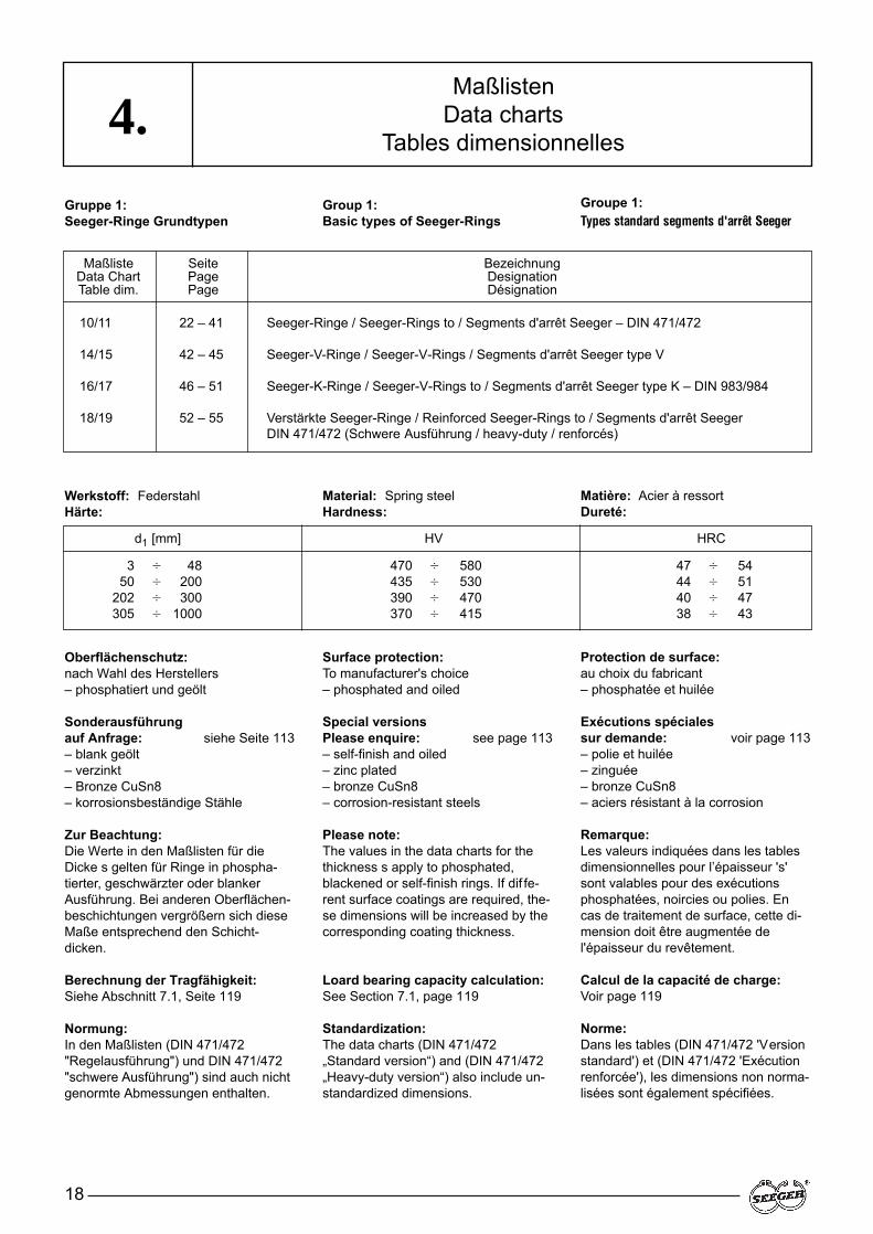
Gruppe 1:Seeger-Ringe Grundtypen
Werkstoff: FederstahlHärte:
Oberflächenschutz:nach Wahl des Herstellers– phosphatiert und geölt
Sonderausführungauf Anfrage: siehe Seite 113– blank geölt– verzinkt– Bronze CuSn8– korrosionsbeständige Stähle
Zur Beachtung:Die Werte in den Maßlisten für dieDicke s gelten für Ringe in phospha-tierter, geschwärzter oder blankerAusführung. Bei anderen Oberflächen-beschichtungen vergrößern sich dieseMaße entsprechend den Schicht-dicken.
Berechnung der Tragfähigkeit:Siehe Abschnitt 7.1, Seite 119
Normung:In den Maßlisten (DIN 471/472"Regelausführung") und DIN 471/472"schwere Ausführung") sind auch nichtgenormte Abmessungen enthalten.
Group 1:Basic types of Seeger-Rings
Material: Spring steelHardness:
Surface protection:To manufacturer's choice– phosphated and oiled
Special versionsPlease enquire: see page 113– self-finish and oiled– zinc plated– bronze CuSn8– corrosion-resistant steels
Please note:The values in the data charts for thethickness s apply to phosphated,blackened or self-finish rings. If dif fe-rent surface coatings are required, the-se dimensions will be increased by thecorresponding coating thickness.
Loard bearing capacity calculation:See Section 7.1, page 119
Standardization:The data charts (DIN 471/472„Standard version“) and (DIN 471/472„Heavy-duty version“) also include un-standardized dimensions.
Groupe 1:Types standard segments d'arrêt Seeger
Matière: Acier à ressortDureté:
Protection de surface:au choix du fabricant– phosphatée et huilée
Exécutions spécialessur demande: voir page 113– polie et huilée– zinguée– bronze CuSn8– aciers résistant à la corrosion
Remarque:Les valeurs indiquées dans les tablesdimensionnelles pour l’épaisseur 's'sont valables pour des exécutionsphosphatées, noircies ou polies. Encas de traitement de surface, cette di-mension doit être augmentée del'épaisseur du revêtement.
Calcul de la capacité de charge:Voir page 119
Norme: Dans les tables (DIN 471/472 'Versionstandard') et (DIN 471/472 'Exécutionrenforcée'), les dimensions non norma-lisées sont également spécifiées.
Maßliste Seite BezeichnungData Chart Page DesignationTable dim. Page Désignation
10/11 22 – 41 Seeger-Ringe / Seeger-Rings to / Segments d'arrêt Seeger – DIN 471/472
14/15 42 – 45 Seeger-V-Ringe / Seeger-V-Rings / Segments d'arrêt Seeger type V
16/17 46 – 51 Seeger-K-Ringe / Seeger-V-Rings to / Segments d'arrêt Seeger type K – DIN 983/984
18/19 52 – 55 Verstärkte Seeger-Ringe / Reinforced Seeger-Rings to / Segments d'arrêt SeegerDIN 471/472 (Schwere Ausführung / heavy-duty / renforcés)
d1 [mm] HV HRC
3 � 48 470 � 580 47 � 5450 � 200 435 � 530 44 � 51
202 � 300 390 � 470 40 � 47305 � 1000 370 � 415 38 � 43
19
4.
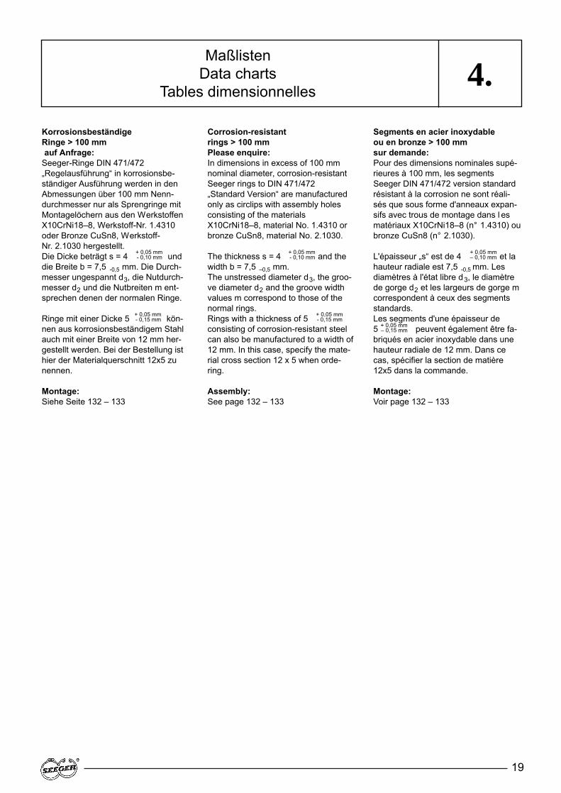
Korrosionsbeständige Ringe > 100 mmauf Anfrage:
Seeger-Ringe DIN 471/472„Regelausführung“ in korrosionsbe-ständiger Ausführung werden in denAbmessungen über 100 mm Nenn-durchmesser nur als Sprengringe mitMontagelöchern aus den WerkstoffenX10CrNi18–8, Werkstoff-Nr. 1.4310oder Bronze CuSn8, Werkstoff-Nr. 2.1030 hergestellt.
+ 0,05 mmDie Dicke beträgt s = 4 - 0,10 mm unddie Breite b = 7,5 -0,5 mm. Die Durch-messer ungespannt d3, die Nutdurch-messer d2 und die Nutbreiten m ent-sprechen denen der normalen Ringe.
+ 0,05 mmRinge mit einer Dicke 5 - 0,15 mm kön-nen aus korrosionsbeständigem Stahlauch mit einer Breite von 12 mm her-gestellt werden. Bei der Bestellung isthier der Materialquerschnitt 12x5 zunennen.
Montage:Siehe Seite 132 – 133
Corrosion-resistant rings > 100 mm Please enquire:In dimensions in excess of 100 mmnominal diameter, corrosion-resistantSeeger rings to DIN 471/472„Standard Version“ are manufacturedonly as circlips with assembly holesconsisting of the materials X10CrNi18–8, material No. 1.4310 orbronze CuSn8, material No. 2.1030.
+ 0,05 mmThe thickness s = 4 - 0,10 mm and thewidth b = 7,5 –0,5 mm.The unstressed diameter d3, the groo-ve diameter d2 and the groove widthvalues m correspond to those of thenormal rings.
+ 0,05 mmRings with a thickness of 5 - 0,15 mm
consisting of corrosion-resistant steelcan also be manufactured to a width of12 mm. In this case, specify the mate-rial cross section 12 x 5 when orde-ring.
Assembly:See page 132 – 133
Segments en acier inoxydable ou en bronze > 100 mm sur demande:Pour des dimensions nominales supé-rieures à 100 mm, les segmentsSeeger DIN 471/472 version standardrésistant à la corrosion ne sont réali-sés que sous forme d'anneaux expan-sifs avec trous de montage dans l esmatériaux X10CrNi18–8 (n° 1.4310) oubronze CuSn8 (n° 2.1030).
+ 0,05 mmL'épaisseur „s“ est de 4 – 0,10 mm et lahauteur radiale est 7,5 -0,5 mm. Lesdiamètres à l'état libre d3, le diamètrede gorge d2 et les largeurs de gorge mcorrespondent à ceux des segmentsstandards.Les segments d'une épaisseur de 5 + 0,05 mm peuvent également être fa-briqués en acier inoxydable dans unehauteur radiale de 12 mm. Dans cecas, spécifier la section de matière12x5 dans la commande.
Montage:Voir page 132 – 133
MaßlistenData charts
Tables dimensionnelles
– 0,15 mm
20
4.Maßlisten
Data chartsTables dimensionnelles
Seeger-Box DIN 471/472
Original Seeger-Ringe in der unver-wüstlichen Kunststoffbox, ideal fürWerkstatt und Betrieb. Übersichtlichangeordnet, leicht zu entnehmen, je-derzeit nachfüllbar. BedarfsorientierteSortierung in den Größen:
DIN 471 Wellendurchmesser 6 – 40 mmDIN 472 Bohrungsdurchmesser 14 – 47 mm
Seeger box to DIN 471/472
Original Seeger-Rings stored ideallyfor the workshop and production shopin an undestructible plastic box.Clearly arranged, easy to remove andcapable of refilling at all times. Thebox contains an assortment orientatedto requirements in the following sizes:
DIN 471 Shaft diameters 6 – 40 mmDIN 472 Bore diameters 14 – 47 mm
Coffret Seeger DIN 471/472
Le coffret en matière plastique indes-tructible, est idéal pour le rangementdes segments Seeger en atelier etdans l'entreprise. Les segments dis-posés de façon très claire peuvent enêtre retirés d'un seul geste et êtrecomplétés à volonté. Classificationcompte tenu des besoins dans les tail-les:DIN 471 Diamètre d'arbre 6 – 40 mmDIN 472 Diamètre d'alésage 14 – 47 mm
Wellen-ø Stückzahl Wellen-ø Stückzahl Bohr-ø Stückzahl Bohr-ø StückzahlShaft ø Quantity Shaft ø Quantity Bore ø Quantity Bore ø Quantity
ø d’arbre Quantité ø d’arbre Quantité ø d’alésage Quantité ø d’alésage Quantitémm mm mm mm
6 25 20 15 14 18 28 158 22 22 15 15 18 30 1510 18 24 15 16 18 32 1511 18 25 15 18 18 35 1212 18 28 12 20 18 36 1214 18 30 12 22 18 38 1215 18 32 12 24 15 40 1016 18 35 12 25 15 42 1017 18 36 10 26 15 47 1018 15 40 10 27 15

21
NotizenNotesNotes
Seeger-Ringe für WellenSeeger-Rings for shafts
Segments extérieurs Seeger
22
10Maßliste
Data chartTable
dimentionelle NennmaßNominal
dimensionDimention nominale
Toleranz Toleranz Gew.Tolerance Tolerance a b d 5 WeightTolérance Tolérance Masse
d1 S d3 max ≈ min kg/1000
BezeichnungDesignationDésignation
A 3 – A 56 / DIN 471
Ring, Ring, Anneau
UngespanntUnstressedA l’état libre
nach Wahl des Herstellers
to manufacturer’s choice
suivant les disponibilitésdu fabricant
A 3 3 0,40 –0,05 2,7 +0,04 –0,15 1,9 0,8 1,0 0,017A 4 4 0,40 –0,05 3,7 +0,04 –0,15 2,2 0,9 1,0 0,022A 5 5 0,60 –0,05 4,7 +0,04 –0,15 2,5 1,1 1,0 0,066A 6 6 0,70 –0,05 5,6 +0,04 –0,15 2,7 1,3 1,2 0,084A 7 7 0,80 –0,05 6,5 +0,06 –0,18 3,1 1,4 1,2 0,121
A 8 8 0,80 –0,05 7,4 +0,06 –0,18 3,2 1,5 1,2 0,158A 9 9 1,00 –0,06 8,4 +0,06 –0,18 3,3 1,7 1,2 0,300A 10 10 1,00 –0,06 9,3 +0,10 –0,36 3,3 1,8 1,5 0,340A 11 11 1,00 –0,06 10,2 +0,10 –0,36 3,3 1,8 1,5 0,410A 12 12 1,00 –0,06 11,0 +0,10 –0,36 3,3 1,8 1,7 0,500
A 13 13 1,00 –0,06 11,9 +0,10 –0,36 3,4 2,0 1,7 0,530A 14 14 1,00 –0,06 12,9 +0,10 –0,36 3,5 2,1 1,7 0,640A 15 15 1,00 –0,06 13,8 +0,10 –0,36 3,6 2,2 1,7 0,670A 16 16 1,00 –0,06 14,7 +0,10 –0,36 3,7 2,2 1,7 0,700A 17 17 1,00 –0,06 15,7 +0,10 –0,36 3,8 2,3 1,7 0,820
A 18 18 1,20 –0,06 16,5 +0,10 –0,36 3,9 2,4 2,0 1,110A 19 19 1,20 –0,06 17,5 +0,10 –0,36 3,9 2,5 2,0 1,220A 20 20 1,20 –0,06 18,5 +0,13 –0,42 4,0 2,6 2,0 1,300A 21 21 1,20 –0,06 19,5 +0,13 –0,42 4,1 2,7 2,0 1,420A 22 22 1,20 –0,06 20,5 +0,13 –0,42 4,2 2,8 2,0 1,500
A 23 23 1,20 –0,06 21,5 +0,13 –0,42 4,3 2,9 2,0 1,630A 24 24 1,20 –0,06 22,2 +0,21 –0,42 4,4 3,0 2,0 1,770A 25 25 1,20 –0,06 23,2 +0,21 –0,42 4,4 3,0 2,0 1,900A 26 26 1,20 –0,06 24,2 +0,21 –0,42 4,5 3,1 2,0 1,960A 27 27 1,20 –0,06 24,9 +0,21 –0,42 4,6 3,1 2,0 2,080
A 28 28 1,50 –0,06 25,9 +0,21 –0,42 4,7 3,2 2,0 2,920A 29 29 1,50 –0,06 26,9 +0,21 –0,42 4,8 3,4 2,0 3,200A 30 30 1,50 –0,06 27,9 +0,21 –0,42 5,0 3,5 2,0 3,320A 31 31 1,50 –0,06 28,6 +0,21 –0,42 5,1 3,5 2,5 3,450A 32 32 1,50 –0,06 29,6 +0,21 –0,42 5,2 3,6 2,5 3,540
A 33 33 1,50 –0,06 30,5 +0,25 –0,50 5,2 3,7 2,5 3,690A 34 34 1,50 –0,06 31,5 +0,25 –0,50 5,4 3,8 2,5 3,800A 35 35 1,50 –0,06 32,2 +0,25 –0,50 5,6 3,9 2,5 4,000A 36 36 1,75 –0,06 33,2 +0,25 –0,50 5,6 4,0 2,5 5,000A 37 37 1,75 –0,06 34,2 +0,25 –0,50 5,7 4,1 2,5 5,370
A 38 38 1,75 –0,06 35,2 +0,25 –0,50 5,8 4,2 2,5 5,620A 39 39 1,75 –0,06 36,0 +0,25 –0,50 5,9 4,3 2,5 5,850A 40 40 1,75 –0,06 36,5 +0,39 –0,90 6,0 4,4 2,5 6,030A 41 41 1,75 –0,06 37,5 +0,39 –0,90 6,2 4,5 2,5 6,215A 42 42 1,75 –0,06 38,5 +0,39 –0,90 6,5 4,5 2,5 6,500
A 44 44 1,75 –0,06 40,5 +0,39 –0,90 6,6 4,6 2,5 7,000A 45 45 1,75 –0,06 41,5 +0,39 –0,90 6,7 4,7 2,5 7,500A 46 46 1,75 –0,06 42,5 +0,39 –0,90 6,7 4,8 2,5 7,600A 47 47 1,75 –0,06 43,5 +0,39 –0,90 6,8 4,9 2,5 7,500A 48 48 1,75 –0,06 44,5 +0,39 –0,90 6,9 5,0 2,5 7,900
A 50 50 2,00 –0,07 45,8 +0,39 –0,90 6,9 5,1 2,5 10,200A 52 52 2,00 –0,07 47,8 +0,39 –0,90 7,0 5,2 2,5 11,100A 54 54 2,00 –0,07 49,8 +0,39 –0,90 7,1 5,3 2,5 11,300A 55 55 2,00 –0,07 50,8 +0,46 –1,10 7,2 5,4 2,5 11,400A 56 56 2,00 –0,07 51,8 +0,46 –1,10 7,3 5,5 2,5 11,800

2,06 360 ZGA-01,93 211 ZGA-07,38 154 ZGA-0
10,40 114 ZGA-014,70 121 ZGA-0
14,20 96 ZGA-030,00 85 ZGA-028,20 84 ZGA-126,10 70 ZGA-124,00 75 ZGA-1
23,20 66 ZGA-122,90 58 ZGA–121,60 50 ZGA–121,00 45 ZGA–121,60 41 ZGA–1
37,10 39 ZGA–236,40 35 ZGA–236,30 32 ZGA–235,40 29 ZGA–235,40 27 ZGA–2
34,70 25 ZGA–233,40 27 ZGA–233,40 25 ZGA–232,90 24 ZGA–233,40 22 ZGA–2
65,00 21 ZGA–264,00 20 ZGA–264,20 19 ZGA–262,80 18 ZGA–261,80 17 ZGA–2
62,20 17 ZGA–261,30 16 ZGA–260,10 16 ZGA–295,80 15 ZGA–296,40 14 ZGA–2
95,00 14 ZGA–295,20 15 ZGA–297,00 14 ZGA–394,50 14 ZGA–393,70 13 ZGA–3
90,70 12 ZGA–391,00 11 ZGA–390,20 11 ZGA–390,70 11 ZGA–390,00 10 ZGA–3
133,00 11 ZGA–3133,00 10 ZGA–3129,00 9 ZGA–3130,00 9 ZGA–3129,00 9 ZGA–3
Seeger-Ringe für WellenSeeger-Rings for shafts
Segments extérieurs Seeger
23
10
Toleranz nabl. ZangeTolerance m* F N FR FRg AN K x1000 Pliers
d2* Tolérance min. t n kN kN g kN mm 2 kN · mm (1/min) Pince
* Siehe Abschnitt 8, Seite 128 · * See section 8, page 128 · * V oir paragraphe 8, page 128
A 3 – A 56 / DIN 471
Nut · Groove · Gorge Ergänzende Daten · Supplementary data · Données complémentaires
2,8 –0,04 0,50 0,10 0,3 0,1 0,47 0,5 0,27 0,93,8 –0,04 0,50 0,10 0,3 0,2 0,50 0,5 0,30 1,24,8 –0,04 0,70 0,10 0,3 0,2 1,00 0,5 0,80 1,55,7 –0,04 0,80 0,15 0,5 0,4 1,45 0,5 0,90 2,86,7 –0,06 0,90 0,15 0,5 0,5 2,60 0,5 1,40 3,2
7,6 –0,06 0,90 0,20 0,6 0,8 3,00 0,5 2,00 4,98,6 –0,06 1,10 0,20 0,6 0,9 3,50 0,5 2,40 5,59,6 –0,11 1,10 0,20 0,6 1,0 4,00 1,0 2,40 6,2
10,5 –0,11 1,10 0,25 0,8 1,4 4,50 1,0 2,40 8,411,5 –0,11 1,10 0,25 0,8 1,5 5,00 1,0 2,40 9,2
12,4 –0,11 1,10 0,30 0,9 2,0 5,80 1,0 2,40 11,913,4 –0,11 1,10 0,30 0,9 2,1 6,40 1,0 2,40 12,914,3 –0,11 1,10 0,35 1,1 2,6 6,90 1,0 2,40 16,115,2 –0,11 1,10 0,40 1,2 3,2 7,40 1,0 2,40 19,616,2 –0,11 1,10 0,40 1,2 3,4 8,00 1,0 2,40 20,8
17,0 –0,11 1,30 0,50 1,5 4,5 17,00 1,5 3,75 27,518,0 –0,11 1,30 0,50 1,5 4,8 17,00 1,5 3,80 29,119,0 –0,13 1,30 0,50 1,5 5,0 17,10 1,5 3,85 30,620,0 –0,13 1,30 0,50 1,5 5,3 16,80 1,5 3,75 32,221,0 –0,13 1,30 0,50 1,5 5,6 16,90 1,5 3,80 33,8
22,0 –0,15 1,30 0,50 1,5 5,9 16,60 1,5 3,80 35,422,9 –0,21 1,30 0,55 1,7 6,7 16,10 1,5 3,65 40,523,9 –0,21 1,30 0,55 1,7 7,0 16,20 1,5 3,70 42,324,9 –0,21 1,30 0,55 1,7 7,3 16,10 1,5 3,70 44,025,6 –0,21 1,30 0,70 2,1 9,6 16,40 1,5 3,80 57,8
26,6 –0,21 1,60 0,70 2,1 10,0 32,10 1,5 7,50 60,027,6 –0,21 1,60 0,70 2,1 10,3 31,80 1,5 7,45 62,028,6 –0,21 1,60 0,70 2,1 10,7 32,10 1,5 7,65 64,029,3 –0,21 1,60 0,85 2,6 13,4 31,50 2,0 5,60 81,030,3 –0,25 1,60 0,85 2,6 13,8 31,20 2,0 5,55 83,0
31,3 –0,25 1,60 0,85 2,6 14,3 31,60 2,0 5,65 86,032,3 –0,25 1,60 0,85 2,6 14,7 31,30 2,0 5,60 88,033,0 –0,25 1,60 1,00 3,0 17,8 30,80 2,0 5,55 107,034,0 –0,25 1,85 1,00 3,0 18,3 49,40 2,0 9,00 110,035,0 –0,25 1,85 1,00 3,0 18,8 50,00 2,0 9,15 113,0
36,0 –0,25 1,85 1,00 3,0 19,3 49,50 2,0 9,10 116,037,0 –0,25 1,85 1,00 3,0 19,9 49,80 2,0 9,25 119,037,5 –0,25 1,85 1,25 3,8 25,3 51,00 2,0 9,50 152,038,5 –0,25 1,85 1,25 3,8 26,0 50,10 2,0 9,40 156,039,5 –0,25 1,85 1,25 3,8 26,7 50,00 2,0 9,45 160,0
41,5 –0,25 1,85 1,25 3,8 28,0 48,50 2,0 9,20 168,042,5 –0,25 1,85 1,25 3,8 28,6 49,00 2,0 9,35 172,043,5 –0,25 1,85 1,25 3,8 29,4 48,90 2,0 9,40 177,044,5 –0,25 1,85 1,25 3,8 30,0 49,50 2,0 9,55 180,045,5 –0,25 1,85 1,25 3,8 30,7 49,40 2,0 9,55 184,0
47,0 –0,25 2,15 1,50 4,5 38,0 73,30 2,0 14,40 228,049,0 –0,25 2,15 1,50 4,5 39,7 73,10 2,5 11,50 238,051,0 –0,30 2,15 1,50 4,5 41,2 71,20 2,5 11,30 247,052,0 –0,30 2,15 1,50 4,5 42,0 71,40 2,5 11,40 252,053,0 –0,30 2,15 1,50 4,5 42,8 70,80 2,5 11,30 257,0

Seeger-Ringe für WellenSeeger-Rings for shafts
Segments extérieurs Seeger
24
10Maßliste
Data chartTable
dimentionelle NennmaßNominal
dimensionDimention nominale
Toleranz Toleranz Gew.Tolerance Tolerance a b d 5 WeightTolérance Tolérance Masse
d1 S d3 max ≈ min kg/1000
BezeichnungDesignationDésignation
A57 – A152 / DIN 471
Ring, Ring, Anneau
UngespanntUnstressedA l’état libre
nach Wahl des Herstellers
to manufacturer’s choice
suivant les disponibilitésdu fabricant
A 57 57 2,00 –0,07 52,8 +0,46 –1,10 7,3 5,5 2,5 12,200A 58 58 2,00 –0,07 53,8 +0,46 –1,10 7,3 5,6 2,5 12,600A 60 60 2,00 –0,07 55,8 +0,46 –1,10 7,4 5,8 2,5 12,900A 62 62 2,00 –0,07 57,8 +0,46 –1,10 7,5 6,0 2,5 14,300A 63 63 2,00 –0,07 58,8 +0,46 –1,10 7,6 6,2 2,5 15,900
A 65 65 2,50 –0,07 60,8 +0,46 –1,10 7,8 6,3 3,0 18,200A 67 67 2,50 –0,07 62,5 +0,46 –1,10 7,9 6,4 3,0 20,300A 68 68 2,50 –0,07 63,5 +0,46 –1,10 8,0 6,5 3,0 21,800A 70 70 2,50 –0,07 65,5 +0,46 –1,10 8,1 6,6 3,0 22,000A 72 72 2,50 –0,07 67,5 +0,46 –1,10 8,2 6,8 3,0 22,500
A 75 75 2,50 –0,07 70,5 +0,46 –1,10 8,4 7,0 3,0 24,600A 77 77 2,50 –0,07 72,5 +0,46 –1,10 8,5 7,2 3,0 25,700A 78 78 2,50 –0,07 73,5 +0,46 –1,10 8,6 7,3 3,0 26,200A 80 80 2,50 –0,07 74,5 +0,46 –1,10 8,6 7,4 3,0 27,300A 82 82 2,50 –0,07 76,5 +0,46 –1,10 8,7 7,6 3,0 31,200
A 85 85 3,00 –0,08 79,5 +0,46 –1,10 8,7 7,8 3,5 36,400A 87 87 3,00 –0,08 81,5 +0,54 –1,30 8,8 7,9 3,5 39,800A 88 88 3,00 –0,08 82,5 +0,54 –1,30 8,8 8,0 3,5 41,200A 90 90 3,00 –0,08 84,5 +0,54 –1,30 8,8 8,2 3,5 44,500A 92 92 3,00 –0,08 86,5 +0,54 –1,30 9,0 8,4 3,5 46,000
A 95 95 3,00 –0,08 89,5 +0,54 –1,30 9,4 8,6 3,5 49,000A 97 97 3,00 –0,08 91,5 +0,54 –1,30 9,4 8,8 3,5 50,200A 98 98 3,00 –0,08 91,5 +0,54 –1,30 9,4 8,8 3,5 50,200A 100 100 3,00 –0,08 94,5 +0,54 –1,30 9,6 9,0 3,5 53,700A 102 102 4,00 –0,10 95,0 +0,54 –1,30 9,7 9,2 3,5 78,000
A 105 105 4,00 –0,10 98,0 +0,54 –1,30 9,9 9,3 3,5 80,000A 107 107 4,00 –0,10 100,0 +0,54 –1,30 10,0 9,5 3,5 81,000A 108 108 4,00 –0,10 100,0 +0,54 –1,30 10,0 9,5 3,5 81,000A 110 110 4,00 –0,10 103,0 +0,54 –1,30 10,1 9,6 3,5 82,000A 112 112 4,00 –0,10 105,0 +0,54 –1,30 10,3 9,7 3,5 83,000
A 115 115 4,00 –0,10 108,0 +0,54 –1,30 10,6 9,8 3,5 84,000A 117 117 4,00 –0,10 110,0 +0,54 –1,30 10,8 10,0 3,5 85,000A 118 118 4,00 –0,10 110,0 +0,54 –1,30 10,8 10,0 3,5 85,000A 120 120 4,00 –0,10 113,0 +0,54 –1,30 11,0 10,2 3,5 86,000A 122 122 4,00 –0,10 115,0 +0,54 –1,30 11,2 10,3 4,0 88,000
A 125 125 4,00 –0,10 118,0 +0,54 –1,30 11,4 10,4 4,0 90,000A 127 127 4,00 –0,10 120,0 +0,54 –1,30 11,4 10,5 4,0 95,000A 128 128 4,00 –0,10 120,0 +0,54 –1,30 11,4 10,5 4,0 95,000A 130 130 4,00 –0,10 123,0 +0,63 –1,50 11,6 10,7 4,0 100,000A 132 132 4,00 –0,10 125,0 +0,63 –1,50 11,7 10,8 4,0 103,000
A 135 135 4,00 –0,10 128,0 +0,63 –1,50 11,8 11,0 4,0 104,000A 137 137 4,00 –0,10 130,0 +0,63 –1,50 11,9 11,0 4,0 107,000A 138 138 4,00 –0,10 130,0 +0,63 –1,50 11,9 11,0 4,0 107,000A 140 140 4,00 –0,10 133,0 +0,63 –1,50 12,0 11,2 4,0 110,000A 142 142 4,00 –0,10 135,0 +0,63 –1,50 12,1 11,3 4,0 112,000
A 145 145 4,00 –0,10 138,0 +0,63 –1,50 12,2 11,5 4,0 115,000A 147 147 4,00 –0,10 140,0 +0,63 –1,50 12,3 11,6 4,0 116,000A 148 148 4,00 –0,10 140,0 +0,63 –1,50 12,3 11,6 4,0 116,000A 150 150 4,00 –0,10 142,0 +0,63 –1,50 13,0 11,8 4,0 120,000A 152 152 4,00 –0,10 143,0 +0,63 –1,50 13,0 11,9 4,0 128,000
Seeger-Ringe für WellenSeeger-Rings for shafts
Segments extérieurs Seeger
25
10
Nut · Groove · Gorge Ergänzende Daten · Supplementary data · Données complémentaires
Toleranz nabl. ZangeTolerance m* F N FR FRg AN K x1000 Pliers
d2* Tolérance min. t n kN kN g kN mm 2 kN · mm (1/min) Pince
* Siehe Abschnitt 8, Seite 128 · * See section 8, page 128 · * V oir paragraphe 8, page 128
A 57 – A 152 / DIN 471
54,0 –0,30 2,15 1,50 4,5 43,7 70,90 2,5 11,40 262,055,0 –0,30 2,15 1,50 4,5 44,3 71,10 2,5 11,50 266,057,0 –0,30 2,15 1,50 4,5 46,0 69,20 2,5 11,30 276,059,0 –0,30 2,15 1,50 4,5 47,5 69,30 2,5 11,40 285,060,0 –0,30 2,15 1,50 4,5 48,3 70,20 2,5 11,60 290,0
62,0 –0,30 2,65 1,50 4,5 49,8 135,00 2,5 22,70 299,064,0 –0,30 2,65 1,50 4,5 51,3 136,00 2,5 23,00 308,065,0 –0,30 2,65 1,50 4,5 52,2 135,00 2,5 23,10 313,067,0 –0,30 2,65 1,50 4,5 53,8 134,00 2,5 23,00 323,069,0 –0,30 2,65 1,50 4,5 55,3 131,00 2,5 22,80 332,0
72,0 –0,30 2,65 1,50 4,5 57,6 130,00 2,5 22,80 346,074,0 –0,30 2,65 1,50 4,5 59,3 131,00 3,0 19,70 356,075,0 –0,30 2,65 1,50 4,5 60,0 131,00 3,0 19,70 360,076,5 –0,30 2,65 1,75 5,3 71,6 128,00 3,0 19,50 430,078,5 –0,30 2,65 1,75 5,3 73,5 128,00 3,0 19,60 441,0
81,5 –0,35 3,15 1,75 5,3 76,2 215,00 3,0 33,40 457,083,5 –0,35 3,15 1,75 5,3 78,2 222,00 3,0 34,80 469,084,5 –0,35 3,15 1,75 5,3 79,0 221,00 3,0 34,80 474,086,5 –0,35 3,15 1,75 5,3 80,0 217,00 3,0 34,40 485,088,5 –0,35 3,15 1,75 5,3 82,0 217,00 3,5 29,60 496,0
91,5 –0,35 3,15 1,75 5,3 85,0 212,00 3,5 29,20 513,093,5 –0,35 3,15 1,75 5,3 87,0 211,00 3,5 29,40 524,094,5 –0,35 3,15 1,75 5,3 88,0 208,00 3,5 29,00 529,096,5 –0,35 3,15 1,75 5,3 90,0 206,00 3,5 29,00 540,098,0 –0,54 4,15 2,00 6,0 104,0 482,00 3,5 68,50 628,0
101,0 –0,54 4,15 2,00 6,0 107,0 471,00 3,5 67,70 646,0103,0 –0,54 4,15 2,00 6,0 110,0 465,00 3,5 67,30 660,0104,0 –0,54 4,15 2,00 6,0 111,0 459,00 3,5 66,30 666,0106,0 –0,54 4,15 2,00 6,0 113,0 457,00 3,5 66,90 678,0108,0 –0,54 4,15 2,00 6,0 115,0 451,00 3,5 66,60 690,0
111,0 –0,54 4,15 2,00 6,0 118,0 438,00 3,5 65,50 709,0113,0 –0,54 4,15 2,00 6,0 120,0 437,00 3,5 65,60 722,0114,0 –0,54 4,15 2,00 6,0 121,0 430,00 3,5 64,80 728,0116,0 –0,54 4,15 2,00 6,0 123,0 424,00 3,5 64,50 741,0118,0 –0,54 4,15 2,00 6,0 125,0 418,00 4,0 56,60 753,0
121,0 –0,63 4,15 2,00 6,0 128,0 411,00 4,0 56,50 772,0123,0 –0,63 4,15 2,00 6,0 130,0 407,00 4,0 56,10 785,0124,0 –0,63 4,15 2,00 6,0 131,0 401,00 4,0 55,60 791,0126,0 –0,63 4,15 2,00 6,0 134,0 395,00 4,0 55,20 804,0128,0 –0,63 4,15 2,00 6,0 136,0 396,00 4,0 55,60 816,0
131,0 –0,63 4,15 2,00 6,0 139,0 389,00 4,0 55,40 835,0133,0 –0,63 4,15 2,00 6,0 141,0 380,00 4,0 54,40 848,0134,0 –0,63 4,15 2,00 6,0 142,0 381,00 4,0 54,70 854,0136,0 –0,63 4,15 2,00 6,0 144,0 376,00 4,0 54,40 867,0138,0 –0,63 4,15 2,00 6,0 146,0 370,00 4,0 54,00 880,0
141,0 –0,63 4,15 2,00 6,0 149,0 367,00 4,0 53,80 898,0143,0 –0,63 4,15 2,00 6,0 151,0 361,00 4,0 53,50 910,0144,0 –0,63 4,15 2,00 6,0 152,0 357,00 4,0 53,00 916,0145,0 –0,63 4,15 2,50 7,5 193,0 357,00 4,0 53,40 1158,0147,0 –0,63 4,15 2,50 7,5 195,0 356,00 4,0 53,10 1174,0
128,00 8 ZGA–3129,00 8 ZGA–3126,00 8 ZGA–3126,00 7 ZGA–3126,00 7 ZGA–3
245,00 7,0 ZGA-3245,00 7,0 ZGA-3244,00 7,0 ZGA-3241,00 7,0 ZGA-3236,00 6,0 ZGA-3
234,00 6,0 ZGA-3238,00 6,0 ZGA-3239,00 5,0 ZGA-3236,00 6,0 ZGA-3237,00 6,0 ZGA-3
405,00 6,0 ZGA-4405,00 5,0 ZGA-4406,00 5,0 ZGA-4401,00 5,0 ZGA-4404,00 5,0 ZGA-4
400,00 5,0 ZGA-4401,00 4,0 ZGA-4397,00 4,0 ZGA-4397,00 4,0 ZGA-4935,00 5,0 ZGA-4
925,00 5,0 ZGA-4920,00 5,0 ZGA-4912,00 4,0 ZGA-4914,00 4,0 ZGA-4910,00 4,0 ZGA-4
894,00 4,0 ZGA-4899,00 4,0 ZGA-4887,00 4,0 ZGA-4882,00 4,0 ZGA-4875,00 4,0 ZGA-5
870,00 3,0 ZGA-5868,00 3,0 ZGA-5859,00 3,0 ZGA-5852,00 3,0 ZGA-5859,00 3,0 ZGA-5
854,00 3,0 ZGA-5840,00 3,0 ZGA-5845,00 3,0 ZGA-5840,00 3,0 ZGA-5833,00 3,0 ZGA-5
833,00 3,0 ZGA-5826,00 3,0 ZGA-5820,00 2,0 ZGA-5825,00 2,0 ZGA-5822,00 3,0 ZGA-5

nach Wahl des Herstellers
manufacturer’s choice
suivant les disponibilitésdu fabricant
UngespanntUnstressedA l’état libre
Seeger-Ringe für WellenSeeger-Rings for shafts
Segments extérieurs Seeger
26
10Maßliste
Data chartTable
dimensionnelle NennmaßNominal
dimensionDimension nominale
Toleranz Toleranz Gew.Tolerance Tolerance a b d 5 WeightTolérance Tolérance Masse
d1 s d3 max. ≈ min. kg/1000
BezeichnungDesignationDésignation
A 155– A 252 / DIN 471
Ring, Ring, Anneau
A 155 155 4,00 –0,10 146,0 +0,63 –1,50 13,0 12,0 4,0 135,000A 157 157 4,00 –0,10 148,0 +0,63 –1,50 13,1 12,0 4,0 140,000A 158 158 4,00 –0,10 148,0 +0,63 –1,50 13,1 12,0 4,0 140,000A 160 160 4,00 –0,10 151,0 +0,63 –1,50 13,3 12,2 4,0 150,000A 162 162 4,00 –0,10 152,5 +0,63 –1,50 13,3 12,3 4,0 155,000
A 165 165 4,00 –0,10 155,5 +0,63 –1,50 13,5 12,5 4,0 160,000A 167 167 4,00 –0,10 157,5 +0,63 –1,50 13,5 12,9 4,0 163,000A 168 168 4,00 –0,10 157,5 +0,63 –1,50 13,5 12,9 4,0 163,000A 170 170 4,00 –0,10 160,5 +0,63 –1,50 13,5 12,9 4,0 170,000A 172 172 4,00 –0,10 160,5 +0,63 –1,50 13,5 12,9 4,0 170,000
A 175 175 4,00 –0,10 165,5 +0,63 –1,50 13,5 12,9 4,0 180,000A 177 177 4,00 –0,10 167,5 +0,63 –1,50 14,2 13,5 4,0 183,000A 178 178 4,00 –0,10 167,5 +0,63 –1,50 14,2 13,5 4,0 183,000A 180 180 4,00 –0,10 170,5 +0,63 –1,50 14,2 13,5 4,0 190,000A 182 182 4,00 –0,10 170,5 +0,63 –1,50 14,2 13,5 4,0 190,000
A 185 185 4,00 –0,10 175,5 +0,63 –1,50 14,2 13,5 4,0 200,000A 187 187 4,00 –0,10 177,5 +0,63 –1,50 14,2 14,0 4,0 203,000A 188 188 4,00 –0,10 177,5 +0,63 –1,50 14,2 14,0 4,0 203,000A 190 190 4,00 –0,10 180,5 +0,72 –1,70 14,2 14,0 4,0 210,000A 192 192 4,00 –0,10 180,5 +0,72 –1,70 14,2 14,0 4,0 210,000
A 195 195 4,00 –0,10 185,5 +0,72 –1,70 14,2 14,0 4,0 220,000A 197 197 4,00 –0,10 187,5 +0,72 –1,70 14,2 14,0 4,0 223,000A 198 198 4,00 –0,10 187,5 +0,72 –1,70 14,2 14,0 4,0 223,000A 200 200 4,00 –0,10 190,5 +0,72 –1,70 14,2 14,0 4,0 230,000A 202 202 5,00 –0,12 190,0 +0,72 –1,70 14,2 14,0 4,0 235,000
A 205 205 5,00 –0,12 193,0 +0,72 –1,70 14,2 14,0 4,0 243,000A 207 207 5,00 –0,12 193,0 +0,72 –1,70 14,2 14,0 4,0 243,000A 208 208 5,00 –0,12 193,0 +0,72 –1,70 14,2 14,0 4,0 243,000A 210 210 5,00 –0,12 198,0 +0,72 –1,70 14,2 14,0 4,0 248,000A 212 212 5,00 –0,12 198,0 +0,72 –1,70 14,2 14,0 4,0 248,000
A 215 215 5,00 –0,12 203,0 +0,72 –1,70 14,2 14,0 4,0 260,000A 217 217 5,00 –0,12 203,0 +0,72 –1,70 14,2 14,0 4,0 260,000A 218 218 5,00 –0,12 203,0 +0,72 –1,70 14,2 14,0 4,0 260,000A 220 220 5,00 –0,12 208,0 +0,72 –1,70 14,2 14,0 4,0 265,000A 222 222 5,00 –0,12 208,0 +0,72 –1,70 14,2 14,0 4,0 265,000
A 225 225 5,00 –0,12 213,0 +0,72 –1,70 14,2 14,0 4,0 280,000A 227 227 5,00 –0,12 213,0 +0,72 –1,70 14,2 14,0 4,0 280,000A 228 228 5,00 –0,12 213,0 +0,72 –1,70 14,2 14,0 4,0 280,000A 230 230 5,00 –0,12 218,0 +0,72 –1,70 14,2 14,0 4,0 290,000A 232 232 5,00 –0,12 218,0 +0,72 –1,70 14,2 14,0 4,0 290,000
A 235 235 5,00 –0,12 223,0 +0,72 –1,70 14,2 14,0 4,0 305,000A 237 237 5,00 –0,12 223,0 +0,72 –1,70 14,2 14,0 4,0 305,000A 238 238 5,00 –0,12 223,0 +0,72 –1,70 14,2 14,0 4,0 305,000A 240 240 5,00 –0,12 228,0 +0,72 –1,70 14,2 14,0 4,0 310,000A 242 242 5,00 –0,12 228,0 +0,72 –1,70 14,2 14,0 4,0 310,000
A 245 245 5,00 –0,12 233,0 +0,72 –1,70 14,2 14,0 4,0 325,000A 247 247 5,00 –0,12 233,0 +0,72 –1,70 14,2 14,0 4,0 325,000A 248 248 5,00 –0,12 233,0 +0,72 –1,70 14,2 14,0 4,0 325,000A 250 250 5,00 –0,12 238,0 +0,72 –1,70 14,2 14,0 4,0 335,000A 252 252 5,00 –0,12 238,0 +0,72 –1,70 16,2 16,0 5,0 335,000

Seeger-Ringe für WellenSeeger-Rings for shafts
Segments extérieurs Seeger
27
10
Nut · Groove · Gorge Ergänzende Daten · Supplementary data · Données complémentaires
Toleranz nabl. ZangeTolerance m* F N FR FRg AN K x1000 Pliers
d2* Tolérance min. t n kN kN g kN mm 2 kN · mm (1/min) Pince
* Siehe Abschnitt 8, Seite 128 · * See section 8, page 128 · * V oir paragraphe 8, page 128
A 155– A 252 / DIN 471
150,0 –0,63 4,15 2,50 7,5 199,0 352,00 4,0 52,60 1198,0152,0 –0,63 4,15 2,50 7,5 202,0 352,00 4,0 52,50 1212,0153,0 –0,63 4,15 2,50 7,5 203,0 353,00 4,0 52,70 1221,0155,0 –0,63 4,15 2,50 7,5 206,0 349,00 4,0 52,20 1237,0157,0 –0,63 4,15 2,50 7,5 208,0 348,00 5,0 41,70 1251,0
160,0 –0,63 4,15 2,50 7,5 212,0 345,00 5,0 41,40 1275,0162,0 –0,63 4,15 2,50 7,5 215,0 354,00 5,0 42,50 1291,0163,0 –0,63 4,15 2,50 7,5 216,0 353,00 5,0 42,40 1300,0165,0 –0,63 4,15 2,50 7,5 219,0 349,00 5,0 41,90 1315,0167,0 –0,63 4,15 2,50 7,5 221,0 344,00 5,0 41,30 1330,0
170,0 –0,63 4,15 2,50 7,5 225,0 340,00 5,0 40,70 1353,0172,0 –0,63 4,15 2,50 7,5 228,0 335,00 5,0 40,20 1370,0173,0 –0,63 4,15 2,50 7,5 229,0 349,00 5,0 42,00 1378,0175,0 –0,63 4,15 2,50 7,5 232,0 345,00 5,0 41,40 1393,0177,0 –0,63 4,15 2,50 7,5 235,0 341,00 5,0 41,00 1410,0
180,0 –0,63 4,15 2,50 7,5 238,0 336,00 5,0 40,40 1432,0182,0 –0,72 4,15 2,50 7,5 241,0 338,00 5,0 40,50 1449,0183,0 –0,72 4,15 2,50 7,5 242,0 337,00 5,0 40,60 1457,0185,0 –0,72 4,15 2,50 7,5 245,0 333,00 5,0 40,00 1471,0187,0 –0,72 4,15 2,50 7,5 248,0 330,00 5,0 39,60 1488,0
190,0 –0,72 4,15 2,50 7,5 251,0 325,00 5,0 39,00 1511,0192,0 –0,72 4,15 2,50 7,5 254,0 322,00 5,0 38,60 1528,0193,0 –0,72 4,15 2,50 7,5 255,0 322,00 5,0 38,70 1535,0195,0 –0,72 4,15 2,50 7,5 258,0 319,00 5,0 38,30 1550,0196,0 –0,72 5,15 3,00 9,0 312,0 624,00 6,0 62,50 1875,0
199,0 –0,72 5,15 3,00 9,0 317,0 611,00 6,0 61,30 1905,0201,0 –0,72 5,15 3,00 9,0 320,0 608,00 6,0 60,90 1921,0202,0 –0,72 5,15 3,00 9,0 321,0 605,00 6,0 60,50 1930,0204,0 –0,72 5,15 3,00 9,0 325,0 598,00 6,0 59,90 1951,0206,0 –0,72 5,15 3,00 9,0 328,0 593,00 6,0 59,50 1969,0
209,0 –0,72 5,15 3,00 9,0 332,0 585,00 6,0 58,50 1997,0211,0 –0,72 5,15 3,00 9,0 336,0 580,00 6,0 58,10 2018,0212,0 –0,72 5,15 3,00 9,0 337,0 577,00 6,0 57,80 2024,0214,0 –0,72 5,15 3,00 9,0 340,0 572,00 6,0 57,30 2045,0216,0 –0,72 5,15 3,00 9,0 343,0 567,00 6,0 56,80 2062,0
219,0 –0,72 5,15 3,00 9,0 349,0 559,00 6,0 56,00 2095,0221,0 –0,72 5,15 3,00 9,0 351,0 555,00 6,0 55,50 2110,0222,0 –0,72 5,15 3,00 9,0 353,0 552,00 6,0 55,40 2120,0224,0 –0,72 5,15 3,00 9,0 356,0 548,00 6,0 55,00 2140,0226,0 –0,72 5,15 3,00 9,0 359,0 543,00 6,0 54,50 2155,0
229,0 –0,72 5,15 3,00 9,0 364,0 537,00 6,0 53,80 2185,0231,0 –0,72 5,15 3,00 9,0 367,0 532,00 6,0 53,40 2202,0232,0 –0,72 5,15 3,00 9,0 369,0 530,00 6,0 53,00 2215,0234,0 –0,72 5,15 3,00 9,0 372,0 530,00 6,0 53,00 2236,0236,0 –0,72 5,15 3,00 9,0 375,0 520,00 6,0 52,20 2250,0
239,0 –0,72 5,15 3,00 9,0 380,0 515,00 6,0 51,50 2280,0241,0 –0,72 5,15 3,00 9,0 383,0 511,00 6,0 51,20 2300,0242,0 –0,72 5,15 3,00 9,0 385,0 508,00 6,0 50,90 2310,0244,0 –0,72 5,15 3,00 9,0 388,0 504,00 6,0 50,50 2330,0244,0 –0,72 5,15 4,00 12,0 519,0 563,00 6,0 56,40 3115,0
814,00 3,0 ZGA-5814,00 3,0 ZGA-5815,00 3,0 ZGA-5806,00 3,0 ZGA-5804,00 3,0 ZGA-5
797,00 3,0 ZGA-5819,00 3,0 ZGA-5815,00 2,0 ZGA-5806,00 2,0 ZGA-5795,00 2,0 ZGA-5
785,00 2,0 ZGA-5774,00 2,0 ZGA-5807,00 2,0 ZGA-5797,00 2,0 ZGA-5789,00 2,0 ZGA-5
777,00 2,0 ZGA-5781,00 2,0 ZGA-5779,00 2,0 ZGA-5770,00 2,0 ZGA-5763,00 2,0 ZGA-5
751,00 2,0 ZGA-5744,00 2,0 ZGA-5739,00 2,0 ZGA-5731,00 2,0 ZGA-5
1430,00 2,0 ZGA-5
1401,00 2,0 ZGA-51392,00 2,0 ZGA-51385,00 2,0 ZGA-51370,00 2,0 ZGA-51359,00 2,0 ZGA-5
1340,00 2,0 ZGA-51330,00 2,0 ZGA-51322,00 2,0 ZGA-51311,00 2,0 ZGA-51300,00 2,0 ZGA-5
1282,00 2,0 ZGA-51271,00 1,0 ZGA-51265,00 1,0 ZGA-51257,00 1,0 ZGA-51243,00 1,0 ZGA-5
1230,00 1,0 ZGA-51220,00 1,0 ZGA-51214,00 1,0 ZGA-51214,00 1,0 ZGA-51193,00 1,0 ZGA-5
1180,00 1,0 ZGA-51171,00 1,0 ZGA-51164,00 1,0 ZGA-51155,00 1,0 ZGA-51290,00 1,0 ZGA-6

nach Wahl des Herstellers
manufacturer’s choice
suivant les disponibilitésdu fabricant
UngespanntUnstressedA l’état libre
Seeger-Ringe für WellenSeeger-Rings for shafts
Segments extérieurs Seeger
28
10Maßliste
Data chartTable
dimensionnelle NennmaßNominal
dimensionDimension nominale
BezeichnungDesignationDésignation
A 255 – A 460 / DIN 471
Ring, Ring, Anneau
A 255 255 5,00 –0,12 240,0 +0,72 –1,70 16,2 16,0 5,0 348,000A 257 257 5,00 –0,12 240,0 +0,72 –1,70 16,2 16,0 5,0 348,000A 258 258 5,00 –0,12 240,0 +0,72 –1,70 16,2 16,0 5,0 348,000A 260 260 5,00 –0,12 245,0 +0,72 –1,70 16,2 16,0 5,0 355,000A 262 262 5,00 –0,12 245,0 +0,72 –1,70 16,2 16,0 5,0 355,000
A 265 265 5,00 –0,12 250,0 +0,72 –1,70 16,2 16,0 5,0 370,000A 267 267 5,00 –0,12 250,0 +0,72 –1,70 16,2 16,0 5,0 370,000A 268 268 5,00 –0,12 250,0 +0,72 –1,70 16,2 16,0 5,0 370,000A 270 270 5,00 –0,12 255,0 +0,81 –2,00 16,2 16,0 5,0 375,000A 272 272 5,00 –0,12 255,0 +0,81 –2,00 16,2 16,0 5,0 375,000
A 275 275 5,00 –0,12 260,0 +0,81 –2,00 16,2 16,0 5,0 390,000A 277 277 5,00 –0,12 260,0 +0,81 –2,00 16,2 16,0 5,0 390,000A 278 278 5,00 –0,12 260,0 +0,81 –2,00 16,2 16,0 5,0 390,000A 280 280 5,00 –0,12 265,0 +0,81 –2,00 16,2 16,0 5,0 398,000A 282 282 5,00 –0,12 265,0 +0,81 –2,00 16,2 16,0 5,0 398,000
A 285 285 5,00 –0,12 270,0 +0,81 –2,00 16,2 16,0 5,0 410,000A 287 287 5,00 –0,12 270,0 +0,81 –2,00 16,2 16,0 5,0 410,000A 288 288 5,00 –0,12 270,0 +0,81 –2,00 16,2 16,0 5,0 410,000A 290 290 5,00 –0,12 275,0 +0,81 –2,00 16,2 16,0 5,0 418,000A 292 292 5,00 –0,12 275,0 +0,81 –2,00 16,2 16,0 5,0 418,000
A 295 295 5,00 –0,12 280,0 +0,81 –2,00 16,2 16,0 5,0 430,000A 297 297 5,00 –0,12 280,0 +0,81 –2,00 16,2 16,0 5,0 430,000A 298 298 5,00 –0,12 280,0 +0,81 –2,00 16,2 16,0 5,0 430,000A 300 300 5,00 –0,12 285,0 +0,81 –2,00 16,2 16,0 5,0 440,000A 305 305 6,00 –0,15 288,0 +0,81 –2,00 20,0 6,0 738,000
A 310 310 6,00 –0,15 293,0 +0,81 –2,00 20,0 6,0 750,000A 315 315 6,00 –0,15 298,0 +0,81 –2,00 20,0 6,0 760,000A 320 320 6,00 –0,15 303,0 +0,81 –2,00 20,0 6,0 770,000A 325 325 6,00 –0,15 308,0 +0,81 –2,00 20,0 6,0 787,000A 330 330 6,00 –0,15 313,0 +0,81 –2,00 20,0 6,0 800,000
A 335 335 6,00 –0,15 318,0 +0,90 –2,00 20,0 6,0 826,000A 340 340 6,00 –0,15 323,0 +0,90 –2,00 20,0 6,0 840,000A 345 345 6,00 –0,15 328,0 +0,90 –2,00 20,0 6,0 845,000A 350 350 6,00 –0,15 333,0 +0,90 –2,00 20,0 6,0 850,000A 355 355 6,00 –0,15 338,0 +0,90 –2,00 20,0 6,0 865,000
A 360 360 6,00 –0,15 343,0 +0,90 –2,00 20,0 6,0 880,000A 365 365 6,00 –0,15 348,0 +0,90 –2,00 20,0 6,0 885,000A 370 370 6,00 –0,15 353,0 +0,90 –2,00 20,0 6,0 890,000A 375 375 6,00 –0,15 358,0 +0,90 –2,00 20,0 6,0 910,000A 380 380 6,00 –0,15 363,0 +0,90 –2,00 20,0 6,0 930,000
A 385 385 6,00 –0,15 368,0 +0,90 –2,00 20,0 6,0 940,000A 390 390 6,00 –0,15 373,0 +0,90 –2,00 20,0 6,0 950,000A 395 395 6,00 –0,15 378,0 +0,90 –2,00 20,0 6,0 990,000A 400 400 6,00 –0,15 383,0 +0,90 –2,00 20,0 6,0 1040,000A 410 410 7,00 –0,15 390,0 +0,90 –2,00 26,0 6,0 1320,000
A 420 420 7,00 –0,15 400,0 +0,90 –2,00 26,0 6,0 1360,000A 430 430 7,00 –0,15 410,0 +1,00 –2,00 26,0 6,0 1390,000A 440 440 7,00 –0,15 420,0 +1,00 –2,00 26,0 6,0 1420,000A 450 450 7,00 –0,15 430,0 +1,00 –2,00 26,0 6,0 1450,000A 460 460 7,00 –0,15 440,0 +1,00 –2,00 26,0 6,0 1520,000
Toleranz Toleranz Gew.Tolerance Tolerance a b d 5 WeightTolérance Tolérance Masse
d1 S d3 max ≈ min kg/1000
Seeger-Ringe für WellenSeeger-Rings for shafts
Segments extérieurs Seeger
29
10
Nut · Groove · Gorge Ergänzende Daten · Supplementary data · Données complémentaires
Toleranz nabl. ZangeTolerance m* F N FR FRg AN K x1000 Pliers
d2* Tolérance min. t n kN kN g kN mm 2 kN · mm (1/min) Pince
* Siehe Abschnitt 8, Seite128 · * See section 8, page 128 · * V oir paragraphe 8, page 128
A 255 – A 460 / DIN 471
247,0 –0,72 5,15 4,00 12,0 525,0 557,00 6,0 55,70 3150,0249,0 –0,72 5,15 4,00 12,0 529,0 551,00 6,0 55,20 3175,0250,0 –0,72 5,15 4,00 12,0 531,0 550,00 6,0 55,10 3190,0252,0 –0,81 5,15 4,00 12,0 535,0 540,00 6,0 54,60 3215,0254,0 –0,81 5,15 4,00 12,0 540,0 542,00 6,0 54,40 3240,0
257,0 –0,81 5,15 4,00 12,0 546,0 536,00 6,0 53,70 3280,0259,0 –0,81 5,15 4,00 12,0 550,0 532,00 6,0 53,30 3300,0260,0 –0,81 5,15 4,00 12,0 553,0 529,00 6,0 53,00 3320,0262,0 –0,81 5,15 4,00 12,0 556,0 525,00 6,0 52,50 3340,0264,0 –0,81 5,15 4,00 12,0 560,0 522,00 6,0 52,00 3365,0
267,0 –0,81 5,15 4,00 12,0 566,0 516,00 6,0 51,00 3400,0269,0 –0,81 5,15 4,00 12,0 571,0 513,00 6,0 51,00 3430,0270,0 –0,81 5,15 4,00 12,0 574,0 510,00 6,0 51,00 3445,0272,0 –0,81 5,15 4,00 12,0 576,0 508,00 6,0 50,00 3460,0274,0 –0,81 5,15 4,00 12,0 580,0 503,00 6,0 50,00 3485,0
277,0 –0,81 5,15 4,00 12,0 587,0 499,00 6,0 50,00 3525,0279,0 –0,81 5,15 4,00 12,0 591,0 494,00 6,0 49,00 3550,0280,0 –0,81 5,15 4,00 12,0 594,0 493,00 6,0 49,00 3565,0282,0 –0,81 5,15 4,00 12,0 599,0 490,00 6,0 49,00 3595,0284,0 –0,81 5,15 4,00 12,0 603,0 487,00 6,0 48,00 3620,0
287,0 –0,81 5,15 4,00 12,0 609,0 481,00 6,0 48,00 3655,0289,0 –0,81 5,15 4,00 12,0 613,0 479,00 6,0 48,00 3680,0290,0 –0,81 5,15 4,00 12,0 615,0 476,00 6,0 47,00 3695,0292,0 –0,81 5,15 4,00 12,0 619,0 475,00 6,0 47,00 3715,0295,0 –0,81 6,20 5,00 15,0 785,0 1036,00 7,0 89,00 4712,0
300,0 –0,81 6,20 5,00 15,0 796,0 1016,00 7,0 87,00 4780,0305,0 –0,81 6,20 5,00 15,0 811,0 1007,00 7,0 86,00 4869,0310,0 –0,81 6,20 5,00 15,0 825,0 988,00 7,0 85,00 4950,0315,0 –0,81 6,20 5,00 15,0 837,0 975,00 7,0 83,00 5027,0320,0 –0,89 6,20 5,00 15,0 850,0 958,00 7,0 82,00 5100,0
325,0 –0,89 6,20 5,00 15,0 864,0 945,00 7,0 81,00 5184,0330,0 –0,89 6,20 5,00 15,0 876,0 932,00 7,0 80,00 5260,0335,0 –0,89 6,20 5,00 15,0 890,0 917,00 7,0 79,00 5341,0340,0 –0,89 6,20 5,00 15,0 903,0 906,00 7,0 77,00 5420,0345,0 –0,89 6,20 5,00 15,0 916,0 894,00 7,0 76,00 5498,0
350,0 –0,89 6,20 5,00 15,0 928,0 880,00 7,0 75,00 5570,0355,0 –0,89 6,20 5,00 15,0 942,0 868,00 7,0 74,00 5655,0360,0 –0,89 6,20 5,00 15,0 955,0 856,00 7,0 73,00 5730,0365,0 –0,89 6,20 5,00 15,0 968,0 847,00 7,0 72,00 5812,0370,0 –0,89 6,20 5,00 15,0 980,0 833,00 7,0 71,00 5880,0
375,0 –0,89 6,20 5,00 15,0 994,0 823,00 7,0 70,00 5969,0380,0 –0,89 6,20 5,00 15,0 1008,0 814,00 7,0 70,00 6050,0385,0 –0,89 6,20 5,00 15,0 1021,0 803,00 7,0 69,00 6126,0390,0 –0,89 6,20 5,00 15,0 1033,0 793,00 7,0 69,00 6200,0398,0 –0,89 7,20 6,00 18,0 1269,0 1616,00 7,0 139,00 7615,0
408,0 –1,00 7,20 6,00 18,0 1300,0 1569,00 7,0 135,00 7803,0418,0 –1,00 7,20 6,00 18,0 1332,0 1540,00 7,0 132,00 7992,0428,0 –1,00 7,20 6,00 18,0 1363,0 1500,00 7,0 129,00 8181,0438,0 –1,00 7,20 6,00 18,0 1393,0 1472,00 7,0 126,00 8360,0448,0 –1,00 7,20 6,00 18,0 1426,0 1443,00 7,0 124,00 8557,0
1276,00 1,0 ZGA-61264,00 1,0 ZGA-61260,00 1,0 ZGA-61250,00 1,0 ZGA-61242,00 1,0 ZGA-6
1228,00 1,0 ZGA-61219,00 1,0 ZGA-61213,00 1,0 ZGA-61203,00 1,0 ZGA-61196,00 1,0 ZGA-6
1183,00 1,0 ZGA-61175,00 1,0 ZGA-61170,00 1,0 ZGA-61164,00 1,0 ZGA-61152,00 1,0 ZGA-6
1143,00 1,0 ZGA-61133,00 1,0 ZGA-61131,00 1,0 ZGA-61124,00 1,0 ZGA-61116,00 1,0 ZGA-6
1103,00 1,0 ZGA-61098,00 1,0 ZGA-61092,00 1,0 ZGA-61088,00 1,0 ZGA-62374,00 1,0 ZGA-6
2329,00 1,0 ZGA-62307,00 1,0 ZGA-62264,00 1,0 ZGA-62233,00 1,0 ZGA-62195,00 1,0 ZGA-6
2166,00 1,0 ZGA-62136,00 1,0 ZGA-62102,00 1,0 ZGA-62074,00 1,0 ZGA-62048,00 1,0 ZGA-6
2017,00 1,0 ZGA-61990,00 1,0 ZGA-61962,00 1,0 ZGA-61943,00 1,0 ZGA-61909,00 1,0 ZGA-6
1886,00 1,0 ZGA-61865,00 1,0 ZGA-61841,00 1,0 ZGA-61817,00 1,0 ZGA-63701,00 1,0 ZGA-7
3595,00 1,0 ZGA-73527,00 1,0 ZGA-73448,00 1,0 ZGA-73373,00 1,0 ZGA-73305,00 1,0 ZGA-7
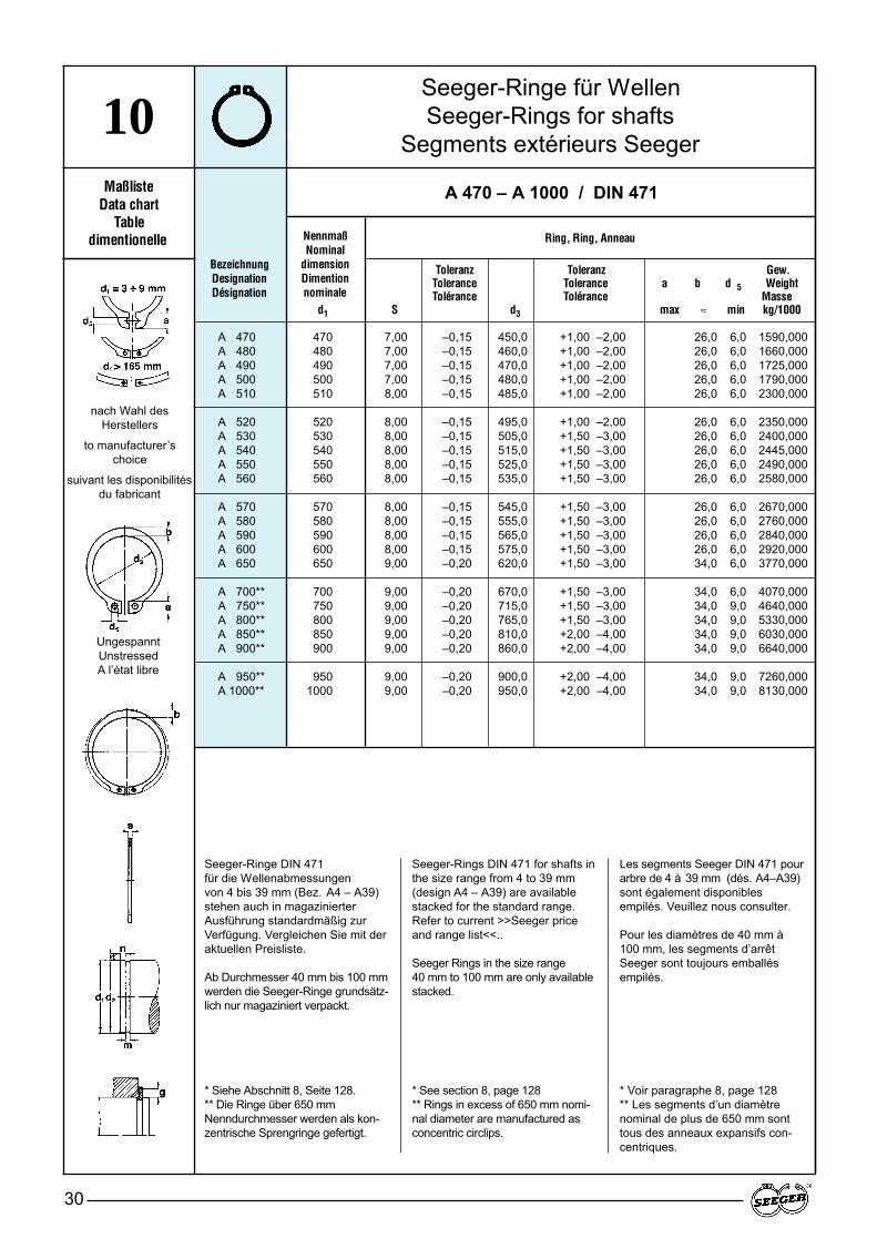
Seeger-Ringe für WellenSeeger-Rings for shafts
Segments extérieurs Seeger
30
10Maßliste
Data chartTable
dimentionelle NennmaßNominal
dimensionDimention nominale
Toleranz Toleranz Gew.Tolerance Tolerance a b d 5 WeightTolérance Tolérance Masse
d1 S d3 max ≈ min kg/1000
BezeichnungDesignationDésignation
Ring, Ring, Anneau
UngespanntUnstressedA l’état libre
nach Wahl des Herstellers
to manufacturer’s choice
suivant les disponibilitésdu fabricant
A 470 – A 1000 / DIN 471
A 470 470 7,00 –0,15 450,0 +1,00 –2,00 26,0 6,0 1590,000A 480 480 7,00 –0,15 460,0 +1,00 –2,00 26,0 6,0 1660,000A 490 490 7,00 –0,15 470,0 +1,00 –2,00 26,0 6,0 1725,000A 500 500 7,00 –0,15 480,0 +1,00 –2,00 26,0 6,0 1790,000A 510 510 8,00 –0,15 485,0 +1,00 –2,00 26,0 6,0 2300,000
A 520 520 8,00 –0,15 495,0 +1,00 –2,00 26,0 6,0 2350,000A 530 530 8,00 –0,15 505,0 +1,50 –3,00 26,0 6,0 2400,000A 540 540 8,00 –0,15 515,0 +1,50 –3,00 26,0 6,0 2445,000A 550 550 8,00 –0,15 525,0 +1,50 –3,00 26,0 6,0 2490,000A 560 560 8,00 –0,15 535,0 +1,50 –3,00 26,0 6,0 2580,000
A 570 570 8,00 –0,15 545,0 +1,50 –3,00 26,0 6,0 2670,000A 580 580 8,00 –0,15 555,0 +1,50 –3,00 26,0 6,0 2760,000A 590 590 8,00 –0,15 565,0 +1,50 –3,00 26,0 6,0 2840,000A 600 600 8,00 –0,15 575,0 +1,50 –3,00 26,0 6,0 2920,000A 650 650 9,00 –0,20 620,0 +1,50 –3,00 34,0 6,0 3770,000
A 700** 700 9,00 –0,20 670,0 +1,50 –3,00 34,0 6,0 4070,000A 750** 750 9,00 –0,20 715,0 +1,50 –3,00 34,0 9,0 4640,000A 800** 800 9,00 –0,20 765,0 +1,50 –3,00 34,0 9,0 5330,000A 850** 850 9,00 –0,20 810,0 +2,00 –4,00 34,0 9,0 6030,000A 900** 900 9,00 –0,20 860,0 +2,00 –4,00 34,0 9,0 6640,000
A 950** 950 9,00 –0,20 900,0 +2,00 –4,00 34,0 9,0 7260,000A 1000** 1000 9,00 –0,20 950,0 +2,00 –4,00 34,0 9,0 8130,000
Seeger-Ringe DIN 471 für die Wellenabmessungen von 4 bis 39 mm (Bez. A4 – A39)stehen auch in magazinierterAusführung standardmäßig zurVerfügung. Vergleichen Sie mit deraktuellen Preisliste.
Ab Durchmesser 40 mm bis 100 mmwerden die Seeger-Ringe grundsätz-lich nur magaziniert verpackt.
* Siehe Abschnitt 8, Seite 128.** Die Ringe über 650 mmNenndurchmesser werden als kon-zentrische Sprengringe gefertigt.
Seeger-Rings DIN 471 for shafts inthe size range from 4 to 39 mm(design A4 – A39) are availablestacked for the standard range.Refer to current >>Seeger priceand range list<<..
Seeger Rings in the size range 40 mm to 100 mm are only availablestacked.
* See section 8, page 128** Rings in excess of 650 mm nomi-nal diameter are manufactured asconcentric circlips.
Les segments Seeger DIN 471 pourarbre de 4 à 39 mm (dés. A4–A39)sont également disponiblesempilés. Veuillez nous consulter.
Pour les diamètres de 40 mm à100 mm, les segments d’arrêtSeeger sont toujours emballésempilés.
* Voir paragraphe 8, page 128** Les segments d’un diamètrenominal de plus de 650 mm sonttous des anneaux expansifs con-centriques.
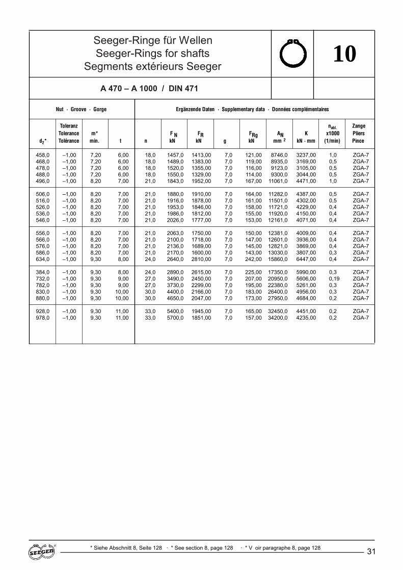
Seeger-Ringe für WellenSeeger-Rings for shafts
Segments extérieurs Seeger
A 470 – A 1000 / DIN 471
31
10
Nut · Groove · Gorge Ergänzende Daten · Supplementary data · Données complémentaires
Toleranz nabl. ZangeTolerance m* F N FR FRg AN K x1000 Pliers
d2* Tolérance min. t n kN kN g kN mm 2 kN · mm (1/min) Pince
* Siehe Abschnitt 8, Seite 128 · * See section 8, page 128 · * V oir paragraphe 8, page 128
458,0 –1,00 7,20 6,00 18,0 1457,0 1413,00 7,0 121,00 8746,0468,0 –1,00 7,20 6,00 18,0 1489,0 1383,00 7,0 119,00 8935,0478,0 –1,00 7,20 6,00 18,0 1520,0 1355,00 7,0 116,00 9123,0488,0 –1,00 7,20 6,00 18,0 1550,0 1329,00 7,0 114,00 9300,0496,0 –1,00 8,20 7,00 21,0 1843,0 1952,00 7,0 167,00 11061,0
506,0 –1,00 8,20 7,00 21,0 1880,0 1910,00 7,0 164,00 11282,0516,0 –1,00 8,20 7,00 21,0 1916,0 1878,00 7,0 161,00 11501,0526,0 –1,00 8,20 7,00 21,0 1953,0 1846,00 7,0 158,00 11721,0536,0 –1,00 8,20 7,00 21,0 1986,0 1812,00 7,0 155,00 11920,0546,0 –1,00 8,20 7,00 21,0 2026,0 1777,00 7,0 153,00 12161,0
556,0 –1,00 8,20 7,00 21,0 2063,0 1750,00 7,0 150,00 12381,0566,0 –1,00 8,20 7,00 21,0 2100,0 1718,00 7,0 147,00 12601,0576,0 –1,00 8,20 7,00 21,0 2136,0 1689,00 7,0 145,00 12821,0586,0 –1,00 8,20 7,00 21,0 2170,0 1600,00 7,0 143,00 13030,0634,0 –1,00 9,30 8,00 24,0 2640,0 2810,00 7,0 242,00 15860,0
384,0 –1,00 9,30 8,00 24,0 2890,0 2615,00 7,0 225,00 17350,0732,0 –1,00 9,30 9,00 27,0 3490,0 2450,00 7,0 207,00 20950,0782,0 –1,00 9,30 9,00 27,0 3730,0 2299,00 7,0 195,00 22380,0830,0 –1,00 9,30 10,00 30,0 4400,0 2166,00 7,0 183,00 26400,0880,0 –1,00 9,30 10,00 30,0 4650,0 2047,00 7,0 173,00 27950,0
928,0 –1,00 9,30 11,00 33,0 5400,0 1945,00 7,0 165,00 32450,0978,0 –1,00 9,30 11,00 33,0 5700,0 1851,00 7,0 157,00 34200,0
3237,00 1,0 ZGA-73169,00 0,5 ZGA-73105,00 0,5 ZGA-73044,00 0,5 ZGA-74471,00 1,0 ZGA-7
4387,00 0,5 ZGA-74302,00 0,5 ZGA-74229,00 0,4 ZGA-74150,00 0,4 ZGA-74071,00 0,4 ZGA-7
4009,00 0,4 ZGA-73936,00 0,4 ZGA-73869,00 0,4 ZGA-73807,00 0,3 ZGA-76447,00 0,4 ZGA-7
5990,00 0,3 ZGA-75606,00 0,19 ZGA-75261,00 0,3 ZGA-74956,00 0,3 ZGA-74684,00 0,2 ZGA-7
4451,00 0,2 ZGA-74235,00 0,2 ZGA-7
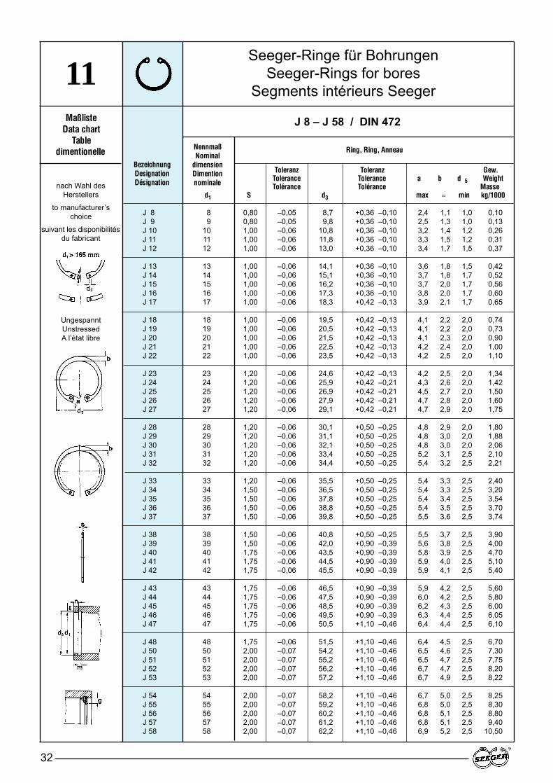
Seeger-Ringe für BohrungenSeeger-Rings for bores
Segments intérieurs Seeger
32
11Maßliste
Data chartTable
dimentionelleBezeichnungDesignationDésignation
J 8 – J 58 / DIN 472
UngespanntUnstressedA l’état libre
nach Wahl des Herstellers
to manufacturer’s choice
suivant les disponibilitésdu fabricant
NennmaßNominal
dimensionDimention nominale
Toleranz Toleranz Gew.Tolerance Tolerance a b d 5 WeightTolérance Tolérance Masse
d1 S d3 max ≈ min kg/1000
Ring, Ring, Anneau
J 8 8 0,80 –0,05 8,7 +0,36 –0,10 2,4 1,1 1,0 0,10J 9 9 0,80 –0,05 9,8 +0,36 –0,10 2,5 1,3 1,0 0,13J 10 10 1,00 –0,06 10,8 +0,36 –0,10 3,2 1,4 1,2 0,26J 11 11 1,00 –0,06 11,8 +0,36 –0,10 3,3 1,5 1,2 0,31J 12 12 1,00 –0,06 13,0 +0,36 –0,10 3,4 1,7 1,5 0,37
J 13 13 1,00 –0,06 14,1 +0,36 –0,10 3,6 1,8 1,5 0,42J 14 14 1,00 –0,06 15,1 +0,36 –0,10 3,7 1,8 1,7 0,52J 15 15 1,00 –0,06 16,2 +0,36 –0,10 3,7 2,0 1,7 0,56J 16 16 1,00 –0,06 17,3 +0,36 –0,10 3,8 2,0 1,7 0,60J 17 17 1,00 –0,06 18,3 +0,42 –0,13 3,9 2,1 1,7 0,65
J 18 18 1,00 –0,06 19,5 +0,42 –0,13 4,1 2,2 2,0 0,74J 19 19 1,00 –0,06 20,5 +0,42 –0,13 4,1 2,2 2,0 0,73J 20 20 1,00 –0,06 21,5 +0,42 –0,13 4,1 2,3 2,0 0,90J 21 21 1,00 –0,06 22,5 +0,42 –0,13 4,2 2,4 2,0 1,00J 22 22 1,00 –0,06 23,5 +0,42 –0,13 4,2 2,5 2,0 1,10
J 23 23 1,20 –0,06 24,6 +0,42 –0,13 4,2 2,5 2,0 1,34J 24 24 1,20 –0,06 25,9 +0,42 –0,21 4,3 2,6 2,0 1,42J 25 25 1,20 –0,06 26,9 +0,42 –0,21 4,5 2,7 2,0 1,50J 26 26 1,20 –0,06 27,9 +0,42 –0,21 4,7 2,8 2,0 1,60J 27 27 1,20 –0,06 29,1 +0,42 –0,21 4,7 2,9 2,0 1,75
J 28 28 1,20 –0,06 30,1 +0,50 –0,25 4,8 2,9 2,0 1,80J 29 29 1,20 –0,06 31,1 +0,50 –0,25 4,8 3,0 2,0 1,88J 30 30 1,20 –0,06 32,1 +0,50 –0,25 4,8 3,0 2,0 2,06J 31 31 1,20 –0,06 33,4 +0,50 –0,25 5,2 3,1 2,5 2,10J 32 32 1,20 –0,06 34,4 +0,50 –0,25 5,4 3,2 2,5 2,21
J 33 33 1,20 –0,06 35,5 +0,50 –0,25 5,4 3,3 2,5 2,40J 34 34 1,50 –0,06 36,5 +0,50 –0,25 5,4 3,3 2,5 3,20J 35 35 1,50 –0,06 37,8 +0,50 –0,25 5,4 3,4 2,5 3,54J 36 36 1,50 –0,06 38,8 +0,50 –0,25 5,4 3,5 2,5 3,70J 37 37 1,50 –0,06 39,8 +0,50 –0,25 5,5 3,6 2,5 3,74
J 38 38 1,50 –0,06 40,8 +0,50 –0,25 5,5 3,7 2,5 3,90J 39 39 1,50 –0,06 42,0 +0,90 –0,39 5,6 3,8 2,5 4,00J 40 40 1,75 –0,06 43,5 +0,90 –0,39 5,8 3,9 2,5 4,70J 41 41 1,75 –0,06 44,5 +0,90 –0,39 5,9 4,0 2,5 5,10J 42 42 1,75 –0,06 45,5 +0,90 –0,39 5,9 4,1 2,5 5,40
J 43 43 1,75 –0,06 46,5 +0,90 –0,39 5,9 4,2 2,5 5,60J 44 44 1,75 –0,06 47,5 +0,90 –0,39 6,0 4,2 2,5 5,80J 45 45 1,75 –0,06 48,5 +0,90 –0,39 6,2 4,3 2,5 6,00J 46 46 1,75 –0,06 49,5 +0,90 –0,39 6,3 4,4 2,5 6,05J 47 47 1,75 –0,06 50,5 +1,10 –0,46 6,4 4,4 2,5 6,10
J 48 48 1,75 –0,06 51,5 +1,10 –0,46 6,4 4,5 2,5 6,70J 50 50 2,00 –0,07 54,2 +1,10 –0,46 6,5 4,6 2,5 7,30J 51 51 2,00 –0,07 55,2 +1,10 –0,46 6,5 4,7 2,5 7,75J 52 52 2,00 –0,07 56,2 +1,10 –0,46 6,7 4,7 2,5 8,20J 53 53 2,00 –0,07 57,2 +1,10 –0,46 6,7 4,9 2,5 8,22
J 54 54 2,00 –0,07 58,2 +1,10 –0,46 6,7 5,0 2,5 8,25J 55 55 2,00 –0,07 59,2 +1,10 –0,46 6,8 5,0 2,5 8,30J 56 56 2,00 –0,07 60,2 +1,10 –0,46 6,8 5,1 2,5 8,80J 57 57 2,00 –0,07 61,2 +1,10 –0,46 6,8 5,1 2,5 9,40J 58 58 2,00 –0,07 62,2 +1,10 –0,46 6,9 5,2 2,5 10,50

Seeger-Ringe für BohrungenSeeger-Rings for bores
Segments intérieurs Seeger
33
11
Nut · Groove · Gorge Ergänzende Daten · Supplementary data · Données complémentaires
Toleranz ZangeTolerance m* F N FR FRg AN K nabl. Pliers
d2* Tolérance min. t n kN kN g kN mm 2 kN · mm x1000 Pince
* Siehe Abschnitt 8, Seite 128 · * See section 8, page 128 · * V oir paragraphe 8, page 128
J 8 – J 58 / DIN 472
8,4 + 0,09 0,90 0,20 0,6 0,86 2,0 0,5 1,5 5,19,4 + 0,09 0,90 0,20 0,6 0,96 2,0 0,5 1,5 5,7
10,4 + 0,11 1,10 0,20 0,6 1,08 4,0 0,5 2,2 6,411,4 + 0,11 1,10 0,20 0,6 1,17 4,0 0,5 2,3 7,012,5 + 0,11 1,10 0,25 0,8 1,60 4,0 0,5 2,3 9,6
13,6 + 0,11 1,10 0,30 0,9 2,10 4,2 0,5 2,3 12,514,6 + 0,11 1,10 0,30 0,9 2,25 4,5 0,5 2,3 13,415,7 + 0,11 1,10 0,35 1,1 2,80 5,0 0,5 2,3 16,816,8 + 0,11 1,10 0,40 1,2 3,40 5,5 1,0 2,6 20,617,8 + 0,11 1,10 0,40 1,2 3,60 6,0 1,0 2,5 21,8
19,0 + 0,13 1,10 0,50 1,5 4,80 6,5 1,0 2,6 29,020,0 + 0,13 1,10 0,50 1,5 5,10 6,8 1,0 2,6 30,621,0 + 0,13 1,10 0,50 1,5 5,40 7,2 1,0 2,6 32,222,0 + 0,13 1,10 0,50 1,5 5,70 7,6 1,0 2,6 33,823,0 + 0,13 1,10 0,50 1,5 5,90 8,0 1,0 2,7 35,3
24,1 + 0,13 1,30 0,55 1,7 6,80 8,0 1,0 4,6 40,725,2 + 0,21 1,30 0,60 1,8 7,70 13,9 1,0 4,6 46,326,2 + 0,21 1,30 0,60 1,8 8,00 14,6 1,0 4,7 48,227,2 + 0,21 1,30 0,60 1,8 8,40 13,8 1,0 4,6 50,128,4 + 0,21 1,30 0,70 2,1 10,10 13,3 1,0 4,5 60,9
29,4 + 0,21 1,30 0,70 2,1 10,50 13,3 1,0 4,5 63,130,4 + 0,25 1,30 0,70 2,1 10,90 13,6 1,0 4,6 65,331,4 + 0,25 1,30 0,70 2,1 11,30 13,7 1,0 4,6 67,532,7 + 0,25 1,30 0,85 2,6 14,10 13,8 1,0 4,7 84,833,7 + 0,25 1,30 0,85 2,6 14,60 13,8 1,0 4,7 87,9
34,7 + 0,25 1,30 0,85 2,6 15,00 14,3 1,0 4,9 90,335,7 + 0,25 1,60 0,85 2,6 15,40 26,2 1,5 6,3 92,637,0 + 0,25 1,60 1,00 3,0 18,80 26,9 1,5 6,4 113,038,0 + 0,25 1,60 1,00 3,0 19,40 26,4 1,5 6,4 116,039,0 + 0,25 1,60 1,00 3,0 19,80 27,1 1,5 6,5 119,0
40,0 + 0,25 1,60 1,00 3,0 22,50 28,2 1,5 6,7 123,041,0 + 0,25 1,60 1,00 3,0 26,00 28,8 1,5 6,9 126,042,5 + 0,25 1,85 1,25 3,8 27,00 44,6 2,0 8,3 162,043,5 + 0,25 1,85 1,25 3,8 27,60 45,0 2,0 8,3 166,044,5 + 0,25 1,85 1,25 3,8 28,40 44,7 2,0 8,4 170,0
45,5 + 0,25 1,85 1,25 3,8 28,80 44,5 2,0 8,4 173,046,5 + 0,25 1,85 1,25 3,8 29,50 43,3 2,0 8,3 177,047,5 + 0,25 1,85 1,25 3,8 30,20 43,1 2,0 8,2 181,048,5 + 0,25 1,85 1,25 3,8 30,80 42,9 2,0 8,2 185,049,5 + 0,25 1,85 1,25 3,8 31,40 43,5 2,0 8,3 189,0
50,5 + 0,30 1,85 1,25 3,8 32,00 43,2 2,0 8,4 193,053,0 + 0,30 2,15 1,50 4,5 40,50 60,8 2,0 12,1 243,054,0 + 0,30 2,15 1,50 4,5 41,20 60,2 2,0 12,0 247,055,0 + 0,30 2,15 1,50 4,5 42,00 60,2 2,0 12,0 252,056,0 + 0,30 2,15 1,50 4,5 42,90 60,7 2,0 12,1 257,0
57,0 + 0,30 2,15 1,50 4,5 43,60 60,4 2,0 12,3 262,058,0 + 0,30 2,15 1,50 4,5 44,40 60,3 2,0 12,5 266,059,0 + 0,30 2,15 1,50 4,5 45,20 60,3 2,0 12,6 271,060,0 + 0,30 2,15 1,50 4,5 46,00 60,8 2,0 12,7 276,061,0 + 0,30 2,15 1,50 4,5 46,70 60,8 2,0 12,7 280,0
9,2 ZGJ-08,4 ZGJ-0
19,6 ZGJ-121,0 ZGJ-120,2 ZGJ-1
20,3 ZGJ-119,7 ZGJ-119,0 ZGJ-118,4 ZGJ-118,1 ZGJ-1
18,2 ZGJ-217,2 ZGJ-216,9 ZGJ-217,2 ZGJ-217,6 ZGJ-2
28,8 ZGJ-228,4 ZGJ-229,0 ZGJ-227,8 ZGJ-226,6 ZGJ-2
26,3 ZGJ-226,8 ZGJ-226,6 ZGJ-226,8 ZGJ-226,6 ZGJ-2
27,0 ZGJ-250,0 ZGJ-250,5 ZGJ-250,2 ZGJ-251,0 ZGJ-2
51,7 ZGJ-252,4 ZGJ-280,1 ZGJ-381,2 ZGJ-380,9 ZGJ-3
80,5 ZGJ-378,6 ZGJ-378,1 ZGJ-377,8 ZGJ-378,9 ZGJ-3
78,5 ZGJ-3111,0 ZGJ-3109,0 ZGJ-3108,0 ZGJ-3110,0 ZGJ-3
110,0 ZGJ-3111,0 ZGJ-3111,0 ZGJ-3112,0 ZGJ-3112,0 ZGJ-3

Seeger-Ringe für BohrungenSeeger-Rings for bores
Segments intérieurs Seeger
34
11Maßliste
Data chartTable
dimensionnelle
Toleranz Toleranz Gew.Tolerance Tolerance a b d 5 WeightTolérance Tolérance Masse
d1 s d3 max. ≈ min. kg/1000
BezeichnungDesignationDésignation
J 60 – J 150 / DIN 472
UngespanntUnstressedA l’état libre
nach Wahl des Herstellers
manufacturer’s choice
suivant les disponibilitésdu fabricant
NennmaßNominal
dimensionDimention nominale
Ring, Ring, Anneau
J 60 60 2,00 –0,07 64,2 +1,10 –0,46 7,3 5,4 2,5 11,10J 62 62 2,00 –0,07 66,2 +1,10 –0,46 7,3 5,5 2,5 11,20J 63 63 2,00 –0,07 67,2 +1,10 –0,46 7,3 5,6 2,5 12,40J 64 64 2,00 –0,07 68,2 +1,10 –0,46 7,4 5,7 2,5 12,45J 65 65 2,50 –0,07 69,2 +1,10 –0,46 7,6 5,8 3,0 14,30
J 67 67 2,50 –0,07 71,5 +1,10 –0,46 7,7 6,0 3,0 15,30J 68 68 2,50 –0,07 72,5 +1,10 –0,46 7,8 6,1 3,0 16,00J 70 70 2,50 –0,07 74,5 +1,10 –0,46 7,8 6,2 3,0 16,50J 72 72 2,50 –0,07 76,5 +1,10 –0,46 7,8 6,4 3,0 18,10J 75 75 2,50 –0,07 79,5 +1,10 –0,46 7,8 6,6 3,0 18,80
J 77 77 2,50 –0,07 82,5 +1,30 –0,54 8,5 6,8 3,0 20,40J 78 78 2,50 –0,07 82,5 +1,30 –0,54 8,5 6,8 3,0 20,40J 80 80 2,50 –0,07 85,5 +1,30 –0,54 8,5 7,0 3,0 22,00J 81 81 2,50 –0,07 86,5 +1,30 –0,54 8,5 7,0 3,0 23,00J 82 82 2,50 –0,07 87,5 +1,30 –0,54 8,5 7,0 3,0 24,00
J 83 83 2,50 –0,07 88,5 +1,30 –0,54 8,5 7,0 3,0 25,00J 85 85 3,00 –0,08 90,5 +1,30 –0,54 8,6 7,2 3,5 25,30J 87 87 3,00 –0,08 93,5 +1,30 –0,54 8,6 7,4 3,5 31,00J 88 88 3,00 –0,08 93,5 +1,30 –0,54 8,6 7,4 3,5 31,00J 90 90 3,00 –0,08 95,5 +1,30 –0,54 8,6 7,6 3,5 33,00
J 92 92 3,00 –0,08 97,5 +1,30 –0,54 8,7 7,8 3,5 35,00J 95 95 3,00 –0,08 100,5 +1,30 –0,54 8,8 8,1 3,5 37,00J 97 97 3,00 –0,08 103,5 +1,30 –0,54 9,0 8,3 3,5 41,00J 98 98 3,00 –0,08 103,5 +1,30 –0,54 9,0 8,3 3,5 41,00J 100 100 3,00 –0,08 105,5 +1,30 –0,54 9,2 8,4 3,5 42,00
J 102 102 4,00 –0,10 108,0 +1,30 –0,54 9,5 8,5 3,5 55,00J 105 105 4,00 –0,10 112,0 +1,30 –0,54 9,5 8,7 3,5 56,00J 107 107 4,00 –0,10 115,0 +1,30 –0,54 9,5 8,9 3,5 60,00J 108 108 4,00 –0,10 115,0 +1,30 –0,54 9,5 8,9 3,5 60,00J 110 110 4,00 –0,10 117,0 +1,30 –0,54 10,4 9,0 3,5 64,50
J 112 112 4,00 –0,10 119,0 +1,30 –0,54 10,5 9,1 3,5 72,00J 115 115 4,00 –0,10 122,0 +1,50 –0,63 10,5 9,3 3,5 74,50J 117 117 4,00 –0,10 125,0 +1,50 –0,63 10,7 9,6 3,5 75,50J 118 118 4,00 –0,10 125,0 +1,50 –0,63 10,7 9,6 3,5 75,50J 120 120 4,00 –0,10 127,0 +1,50 –0,63 11,0 9,7 3,5 77,00
J 122 122 4,00 –0,10 129,0 +1,50 –0,63 11,0 9,8 4,0 78,00J 125 125 4,00 –0,10 132,0 +1,50 –0,63 11,0 10,0 4,0 79,00J 127 127 4,00 –0,10 135,0 +1,50 –0,63 11,0 10,0 4,0 81,00J 128 128 4,00 –0,10 135,0 +1,50 –0,63 11,0 10,2 4,0 81,00J 130 130 4,00 –0,10 137,0 +1,50 –0,63 11,0 10,2 4,0 82,00
J 132 132 4,00 –0,10 139,0 +1,50 –0,63 11,0 10,3 4,0 83,00J 135 135 4,00 –0,10 142,0 +1,50 –0,63 11,2 10,5 4,0 84,00J 137 137 4,00 –0,10 145,0 +1,50 –0,63 11,2 10,6 4,0 86,00J 138 138 4,00 –0,10 145,0 +1,50 –0,63 11,2 10,6 4,0 86,00J 140 140 4,00 –0,10 147,0 +1,50 –0,63 11,2 10,7 4,0 87,50
J 142 142 4,00 –0,10 149,0 +1,50 –0,63 11,3 10,8 4,0 89,00J 145 145 4,00 –0,10 152,0 +1,50 –0,63 11,4 10,9 4,0 93,00J 147 147 4,00 –0,10 155,0 +1,50 –0,63 11,8 11,1 4,0 100,00J 148 148 4,00 –0,10 155,0 +1,50 –0,63 11,8 11,1 4,0 100,00J 150 150 4,00 –0,10 158,0 +1,50 –0,63 12,0 11,2 4,0 105,00

Seeger-Ringe für BohrungenSeeger-Rings for bores
Segments intérieurs Seeger
35
11
Nut · Groove · Gorge Ergänzende Daten · Supplementary data · Données complémentaires
Toleranz ZangeTolerance m* F N FR FRg AN K nabl. Pliers
d2* Tolérance min. t n kN kN g kN mm 2 kN · mm x1000 Pince
* Siehe Abschnitt 8, Seite 128 · * See section 8, page 128 · * V oir paragraphe 8, page 128
J 60 – J 150 / DIN 472
63,0 + 0,30 2,15 1,50 4,5 48,30 61,0 2,0 13,0 290,065,0 + 0,30 2,15 1,50 4,5 49,80 60,9 2,0 13,0 299,066,0 + 0,30 2,15 1,50 4,5 50,60 60,8 2,0 13,0 304,067,0 + 0,30 2,15 1,50 4,5 51,40 60,6 2,0 13,0 308,068,0 + 0,30 2,65 1,50 4,5 51,80 121,0 2,5 20,8 313,0
70,0 + 0,30 2,65 1,50 4,5 53,80 121,0 2,5 21,1 323,071,0 + 0,30 2,65 1,50 4,5 56,20 119,0 2,5 21,0 337,073,0 + 0,30 2,65 1,50 4,5 56,20 119,0 2,5 21,0 337,075,0 + 0,30 2,65 1,50 4,5 58,00 119,0 2,5 21,0 346,078,0 + 0,30 2,65 1,50 4,5 60,00 118,0 2,5 21,0 360,0
80,0 + 0,30 2,65 1,50 4,5 61,60 121,0 2,5 21,5 370,081,0 + 0,35 2,65 1,50 4,5 62,30 122,0 2,5 21,8 374,083,5 + 0,35 2,65 1,75 5,3 74,60 120,0 2,5 21,8 448,084,5 + 0,35 2,65 1,75 5,3 75,80 119,0 2,5 21,6 455,085,5 + 0,35 2,65 1,75 5,3 76,60 119,0 2,5 21,4 460,0
86,5 + 0,35 2,65 1,75 5,3 77,50 118,0 2,5 21,2 466,088,5 + 0,35 3,15 1,75 5,3 79,50 201,0 3,0 31,2 477,090,5 + 0,35 3,15 1,75 5,3 81,30 204,0 3,0 31,8 488,091,5 + 0,35 3,15 1,75 5,3 82,00 209,0 3,0 32,7 493,093,5 + 0,35 3,15 1,75 5,3 84,00 199,0 3,0 31,4 504,0
95,5 + 0,35 3,15 1,75 5,3 85,00 201,0 3,0 32,0 515,098,5 + 0,35 3,15 1,75 5,3 88,00 195,0 3,0 31,4 532,0
100,5 + 0,35 3,15 1,75 5,3 90,00 193,0 3,0 31,2 543,0101,5 + 0,35 3,15 1,75 5,3 91,00 191,0 3,0 31,0 548,0103,5 + 0,35 3,15 1,75 5,3 93,00 188,0 3,0 30,8 559,0
106,0 + 0,54 4,15 2,00 6,0 108,00 439,0 3,0 72,6 653,0109,0 + 0,54 4,15 2,00 6,0 112,00 436,0 3,0 73,0 672,0111,0 + 0,54 4,15 2,00 6,0 114,00 425,0 3,0 71,6 684,0112,0 + 0,54 4,15 2,00 6,0 115,00 419,0 3,0 71,0 691,0114,0 + 0,54 4,15 2,00 6,0 117,00 415,0 3,0 71,0 704,0
116,0 + 0,54 4,15 2,00 6,0 119,00 418,0 3,0 72,0 715,0119,0 + 0,54 4,15 2,00 6,0 122,00 409,0 3,0 71,2 735,0121,0 + 0,63 4,15 2,00 6,0 124,00 399,0 3,0 70,0 747,0122,0 + 0,63 4,15 2,00 6,0 125,00 394,0 3,0 69,3 754,0124,0 + 0,63 4,15 2,00 6,0 127,00 396,0 3,0 70,0 767,0
126,0 + 0,63 4,15 2,00 6,0 129,00 399,0 3,0 71,0 779,0129,0 + 0,63 4,15 2,00 6,0 132,00 385,0 3,0 70,0 797,0131,0 + 0,63 4,15 2,00 6,0 135,00 383,0 3,0 70,0 810,0132,0 + 0,63 4,15 2,00 6,0 136,00 378,0 3,0 69,0 816,0134,0 + 0,63 4,15 2,00 6,0 138,00 374,0 3,0 69,0 829,0
136,0 + 0,63 4,15 2,00 6,0 140,00 366,0 3,0 68,0 842,0139,0 + 0,63 4,15 2,00 6,0 143,00 358,0 3,0 67,0 860,0141,0 + 0,63 4,15 2,00 6,0 145,00 356,0 3,0 67,0 874,0142,0 + 0,63 4,15 2,00 6,0 146,00 352,0 3,0 66,5 880,0144,0 + 0,63 4,15 2,00 6,0 148,00 350,0 3,0 66,5 892,0
146,0 + 0,63 4,15 2,00 6,0 150,00 342,0 3,0 65,5 905,0149,0 + 0,63 4,15 2,00 6,0 153,00 336,0 3,0 65,0 923,0151,0 + 0,63 4,15 2,00 6,0 156,00 336,0 3,0 65,0 936,0152,0 + 0,63 4,15 2,00 6,0 157,00 331,0 3,0 64,5 942,0155,0 + 0,63 4,15 2,50 7,5 191,00 326,0 3,0 64,0 1198,0
113,0 ZGJ-3112,0 ZGJ-3112,0 ZGJ-3112,0 ZGJ-3220,0 ZGJ-3
222,0 ZGJ-3218,0 ZGJ-3218,0 ZGJ-3217,0 ZGJ-3215,0 ZGJ-3
220,0 ZGJ-3221,0 ZGJ-3219,0 ZGJ-3216,0 ZGJ-3214,0 ZGJ-3
213,0 ZGJ-3364,0 ZGJ-4370,0 ZGJ-4380,0 ZGJ-4364,0 ZGJ-4
371,0 ZGJ-4365,0 ZGJ-4364,0 ZGJ-4361,0 ZGJ-4359,0 ZGJ-4
846,0 ZGJ-4850,0 ZGJ-4834,0 ZGJ-4825,0 ZGJ-4824,0 ZGJ-4
837,0 ZGJ-4829,0 ZGJ-4814,0 ZGJ-4807,0 ZGJ-4818,0 ZGJ-4
829,0 ZGJ-5809,0 ZGJ-5808,0 ZGJ-5802,0 ZGJ-5801,0 ZGJ-5
789,0 ZGJ-5781,0 ZGJ-5780,0 ZGJ-5775,0 ZGJ-5775,0 ZGJ-5
764,0 ZGJ-5757,0 ZGJ-5757,0 ZGJ-5753,0 ZGJ-5748,0 ZGJ-5
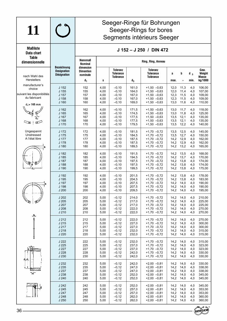
Seeger-Ringe für BohrungenSeeger-Rings for bores
Segments intérieurs Seeger
36
11Maßliste
Data chartTable
dimensionnelle
Toleranz Toleranz Gew.Tolerance Tolerance a b d 5 WeightTolérance Tolérance Masse
d1 s d3 max. ≈ min. kg/1000
BezeichnungDesignationDésignation
J 152 – J 250 / DIN 472
UngespanntUnstressedA l’état libre
nach Wahl des Herstellers
manufacturer’s choice
suivant les disponibilitésdu fabricant
NennmaßNominal
dimensionDimention nominale
Ring, Ring, Anneau
J 152 152 4,00 –0,10 161,0 +1,50 –0,63 12,0 11,3 4,0 106,00J 155 155 4,00 –0,10 164,0 +1,50 –0,63 12,0 11,4 4,0 107,00J 157 157 4,00 –0,10 167,0 +1,50 –0,63 12,3 11,5 4,0 109,00J 158 158 4,00 –0,10 167,0 +1,50 –0,63 12,3 11,5 4,0 109,00J 160 160 4,00 –0,10 169,0 +1,50 –0,63 13,0 11,6 4,0 110,00
J 162 162 4,00 –0,10 171,5 +1,50 –0,63 13,0 11,7 4,0 118,00J 165 165 4,00 –0,10 174,5 +1,50 –0,63 13,0 11,8 4,0 125,00J 167 167 4,00 –0,10 177,5 +1,50 –0,63 13,5 12,1 4,0 135,00J 168 168 4,00 –0,10 177,5 +1,50 –0,63 13,5 12,1 4,0 135,00J 170 170 4,00 –0,10 179,5 +1,50 –0,63 13,5 12,2 4,0 140,00
J 172 172 4,00 –0,10 181,5 +1,70 –0,72 13,5 12,5 4,0 145,00J 175 175 4,00 –0,10 184,5 +1,70 –0,72 13,5 12,7 4,0 150,00J 177 177 4,00 –0,10 187,5 +1,70 –0,72 14,2 12,9 4,0 162,00J 178 178 4,00 –0,10 187,5 +1,70 –0,72 14,2 12,9 4,0 162,00J 180 180 4,00 –0,10 189,5 +1,70 –0,72 14,2 13,2 4,0 165,00
J 182 182 4,00 –0,10 191,5 +1,70 –0,72 14,2 13,5 4,0 168,00J 185 185 4,00 –0,10 194,5 +1,70 –0,72 14,2 13,7 4,0 170,00J 187 187 4,00 –0,10 197,5 +1,70 –0,72 14,2 13,8 4,0 174,00J 188 188 4,00 –0,10 197,5 +1,70 –0,72 14,2 13,8 4,0 174,00J 190 190 4,00 –0,10 199,5 +1,70 –0,72 14,2 13,8 4,0 175,00
J 192 192 4,00 –0,10 201,5 +1,70 –0,72 14,2 13,8 4,0 178,00J 195 195 4,00 –0,10 204,5 +1,70 –0,72 14,2 13,8 4,0 183,00J 197 197 4,00 –0,10 207,5 +1,70 –0,72 14,2 14,0 4,0 190,00J 198 198 4,00 –0,10 207,5 +1,70 –0,72 14,2 14,0 4,0 190,00J 200 200 4,00 –0,10 209,5 +1,70 –0,72 14,2 14,0 4,0 195,00
J 202 202 5,00 –0,12 214,0 +1,70 –0,72 14,2 14,0 4,0 210,00J 205 205 5,00 –0,12 217,0 +1,70 –0,72 14,2 14,0 4,0 225,00J 207 207 5,00 –0,12 217,0 +1,70 –0,72 14,2 14,0 4,0 225,00J 208 208 5,00 –0,12 222,0 +1,70 –0,72 14,2 14,0 4,0 270,00J 210 210 5,00 –0,12 222,0 +1,70 –0,72 14,2 14,0 4,0 270,00
J 212 212 5,00 –0,12 222,0 +1,70 –0,72 14,2 14,0 4,0 270,00J 215 215 5,00 –0,12 227,0 +1,70 –0,72 14,2 14,0 4,0 300,00J 217 217 5,00 –0,12 227,0 +1,70 –0,72 14,2 14,0 4,0 300,00J 218 218 5,00 –0,12 232,0 +1,70 –0,72 14,2 14,0 4,0 315,00J 220 220 5,00 –0,12 232,0 +1,70 –0,72 14,2 14,0 4,0 315,00
J 222 222 5,00 –0,12 232,0 +1,70 –0,72 14,2 14,0 4,0 315,00J 225 225 5,00 –0,12 237,0 +1,70 –0,72 14,2 14,0 4,0 323,00J 227 227 5,00 –0,12 237,0 +1,70 –0,72 14,2 14,0 4,0 323,00J 228 228 5,00 –0,12 242,0 +1,70 –0,72 14,2 14,0 4,0 330,00J 230 230 5,00 –0,12 242,0 +1,70 –0,72 14,2 14,0 4,0 330,00
J 232 232 5,00 –0,12 242,0 +2,00 –0,81 14,2 14,0 4,0 330,00J 235 235 5,00 –0,12 247,0 +2,00 –0,81 14,2 14,0 4,0 338,00J 237 237 5,00 –0,12 247,0 +2,00 –0,81 14,2 14,0 4,0 338,00J 238 238 5,00 –0,12 252,0 +2,00 –0,81 14,2 14,0 4,0 345,00J 240 240 5,00 –0,12 252,0 +2,00 –0,81 14,2 14,0 4,0 345,00
J 242 242 5,00 –0,12 252,0 +2,00 –0,81 14,2 14,0 4,0 345,00J 245 245 5,00 –0,12 257,0 +2,00 –0,81 14,2 14,0 4,0 353,00J 247 247 5,00 –0,12 257,0 +2,00 –0,81 14,2 14,0 4,0 353,00J 248 248 5,00 –0,12 262,0 +2,00 –0,81 14,2 14,0 4,0 360,00J 250 250 5,00 –0,12 262,0 +2,00 –0,81 14,2 14,0 4,0 360,00
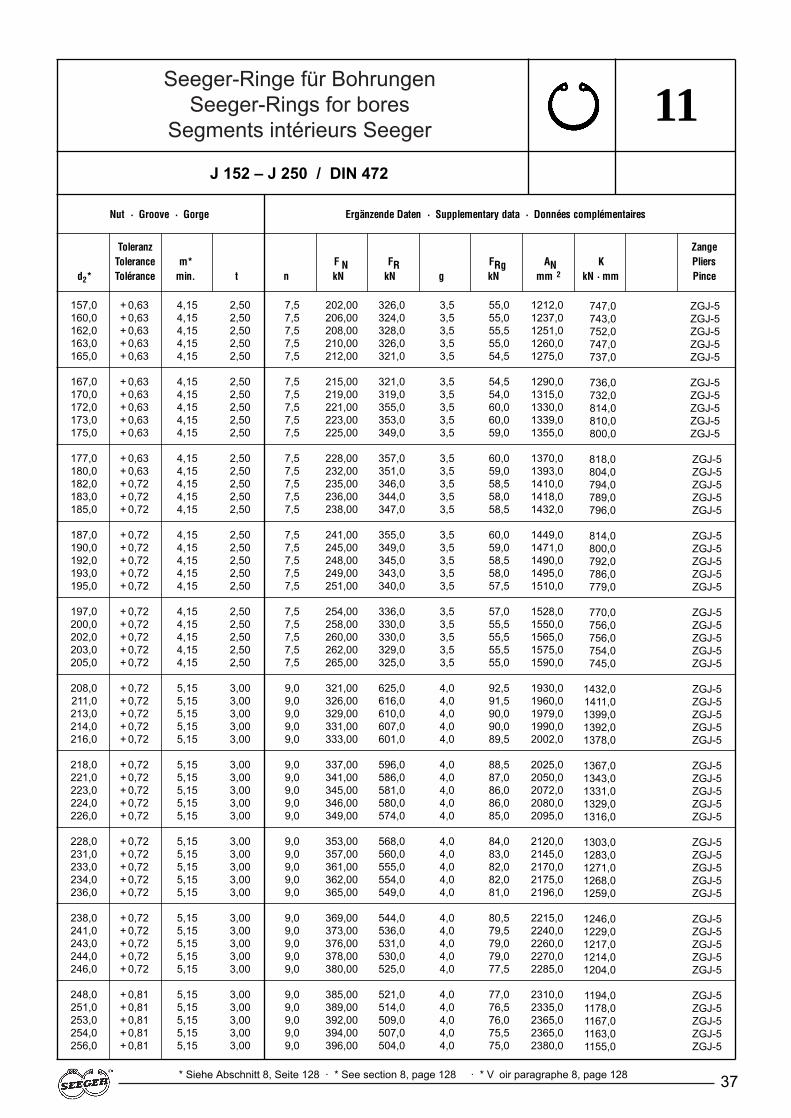
Seeger-Ringe für BohrungenSeeger-Rings for bores
Segments intérieurs Seeger
37
11
Nut · Groove · Gorge Ergänzende Daten · Supplementary data · Données complémentaires
Toleranz ZangeTolerance m* F N FR FRg AN K nabl. Pliers
d2* Tolérance min. t n kN kN g kN mm 2 kN · mm x1000 Pince
* Siehe Abschnitt 8, Seite 128 · * See section 8, page 128 · * V oir paragraphe 8, page 128
J 152 – J 250 / DIN 472
157,0 + 0,63 4,15 2,50 7,5 202,00 326,0 3,5 55,0 1212,0160,0 + 0,63 4,15 2,50 7,5 206,00 324,0 3,5 55,0 1237,0162,0 + 0,63 4,15 2,50 7,5 208,00 328,0 3,5 55,5 1251,0163,0 + 0,63 4,15 2,50 7,5 210,00 326,0 3,5 55,0 1260,0165,0 + 0,63 4,15 2,50 7,5 212,00 321,0 3,5 54,5 1275,0
167,0 + 0,63 4,15 2,50 7,5 215,00 321,0 3,5 54,5 1290,0170,0 + 0,63 4,15 2,50 7,5 219,00 319,0 3,5 54,0 1315,0172,0 + 0,63 4,15 2,50 7,5 221,00 355,0 3,5 60,0 1330,0173,0 + 0,63 4,15 2,50 7,5 223,00 353,0 3,5 60,0 1339,0175,0 + 0,63 4,15 2,50 7,5 225,00 349,0 3,5 59,0 1355,0
177,0 + 0,63 4,15 2,50 7,5 228,00 357,0 3,5 60,0 1370,0180,0 + 0,63 4,15 2,50 7,5 232,00 351,0 3,5 59,0 1393,0182,0 + 0,72 4,15 2,50 7,5 235,00 346,0 3,5 58,5 1410,0183,0 + 0,72 4,15 2,50 7,5 236,00 344,0 3,5 58,0 1418,0185,0 + 0,72 4,15 2,50 7,5 238,00 347,0 3,5 58,5 1432,0
187,0 + 0,72 4,15 2,50 7,5 241,00 355,0 3,5 60,0 1449,0190,0 + 0,72 4,15 2,50 7,5 245,00 349,0 3,5 59,0 1471,0192,0 + 0,72 4,15 2,50 7,5 248,00 345,0 3,5 58,5 1490,0193,0 + 0,72 4,15 2,50 7,5 249,00 343,0 3,5 58,0 1495,0195,0 + 0,72 4,15 2,50 7,5 251,00 340,0 3,5 57,5 1510,0
197,0 + 0,72 4,15 2,50 7,5 254,00 336,0 3,5 57,0 1528,0200,0 + 0,72 4,15 2,50 7,5 258,00 330,0 3,5 55,5 1550,0202,0 + 0,72 4,15 2,50 7,5 260,00 330,0 3,5 55,5 1565,0203,0 + 0,72 4,15 2,50 7,5 262,00 329,0 3,5 55,5 1575,0205,0 + 0,72 4,15 2,50 7,5 265,00 325,0 3,5 55,0 1590,0
208,0 + 0,72 5,15 3,00 9,0 321,00 625,0 4,0 92,5 1930,0211,0 + 0,72 5,15 3,00 9,0 326,00 616,0 4,0 91,5 1960,0213,0 + 0,72 5,15 3,00 9,0 329,00 610,0 4,0 90,0 1979,0214,0 + 0,72 5,15 3,00 9,0 331,00 607,0 4,0 90,0 1990,0216,0 + 0,72 5,15 3,00 9,0 333,00 601,0 4,0 89,5 2002,0
218,0 + 0,72 5,15 3,00 9,0 337,00 596,0 4,0 88,5 2025,0221,0 + 0,72 5,15 3,00 9,0 341,00 586,0 4,0 87,0 2050,0223,0 + 0,72 5,15 3,00 9,0 345,00 581,0 4,0 86,0 2072,0224,0 + 0,72 5,15 3,00 9,0 346,00 580,0 4,0 86,0 2080,0226,0 + 0,72 5,15 3,00 9,0 349,00 574,0 4,0 85,0 2095,0
228,0 + 0,72 5,15 3,00 9,0 353,00 568,0 4,0 84,0 2120,0231,0 + 0,72 5,15 3,00 9,0 357,00 560,0 4,0 83,0 2145,0233,0 + 0,72 5,15 3,00 9,0 361,00 555,0 4,0 82,0 2170,0234,0 + 0,72 5,15 3,00 9,0 362,00 554,0 4,0 82,0 2175,0236,0 + 0,72 5,15 3,00 9,0 365,00 549,0 4,0 81,0 2196,0
238,0 + 0,72 5,15 3,00 9,0 369,00 544,0 4,0 80,5 2215,0241,0 + 0,72 5,15 3,00 9,0 373,00 536,0 4,0 79,5 2240,0243,0 + 0,72 5,15 3,00 9,0 376,00 531,0 4,0 79,0 2260,0244,0 + 0,72 5,15 3,00 9,0 378,00 530,0 4,0 79,0 2270,0246,0 + 0,72 5,15 3,00 9,0 380,00 525,0 4,0 77,5 2285,0
248,0 + 0,81 5,15 3,00 9,0 385,00 521,0 4,0 77,0 2310,0251,0 + 0,81 5,15 3,00 9,0 389,00 514,0 4,0 76,5 2335,0253,0 + 0,81 5,15 3,00 9,0 392,00 509,0 4,0 76,0 2365,0254,0 + 0,81 5,15 3,00 9,0 394,00 507,0 4,0 75,5 2365,0256,0 + 0,81 5,15 3,00 9,0 396,00 504,0 4,0 75,0 2380,0
747,0 ZGJ-5743,0 ZGJ-5752,0 ZGJ-5747,0 ZGJ-5737,0 ZGJ-5
736,0 ZGJ-5732,0 ZGJ-5814,0 ZGJ-5810,0 ZGJ-5800,0 ZGJ-5
818,0 ZGJ-5804,0 ZGJ-5794,0 ZGJ-5789,0 ZGJ-5796,0 ZGJ-5
814,0 ZGJ-5800,0 ZGJ-5792,0 ZGJ-5786,0 ZGJ-5779,0 ZGJ-5
770,0 ZGJ-5756,0 ZGJ-5756,0 ZGJ-5754,0 ZGJ-5745,0 ZGJ-5
1432,0 ZGJ-51411,0 ZGJ-51399,0 ZGJ-51392,0 ZGJ-51378,0 ZGJ-5
1367,0 ZGJ-51343,0 ZGJ-51331,0 ZGJ-51329,0 ZGJ-51316,0 ZGJ-5
1303,0 ZGJ-51283,0 ZGJ-51271,0 ZGJ-51268,0 ZGJ-51259,0 ZGJ-5
1246,0 ZGJ-51229,0 ZGJ-51217,0 ZGJ-51214,0 ZGJ-51204,0 ZGJ-5
1194,0 ZGJ-51178,0 ZGJ-51167,0 ZGJ-51163,0 ZGJ-51155,0 ZGJ-5
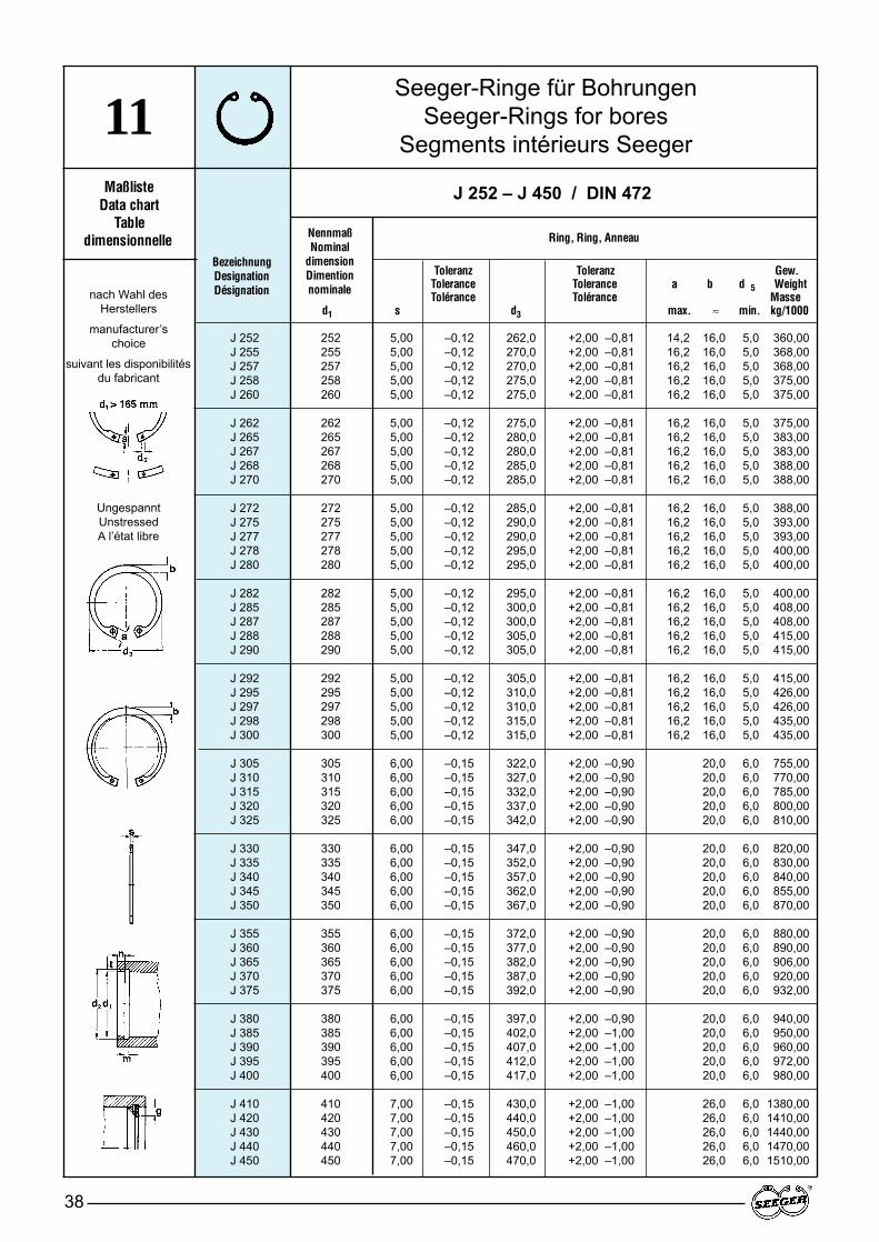
Seeger-Ringe für BohrungenSeeger-Rings for bores
Segments intérieurs Seeger
38
11Maßliste
Data chartTable
dimensionnelle
Toleranz Toleranz Gew.Tolerance Tolerance a b d 5 WeightTolérance Tolérance Masse
d1 s d3 max. ≈ min. kg/1000
BezeichnungDesignationDésignation
J 252 – J 450 / DIN 472
UngespanntUnstressedA l’état libre
nach Wahl des Herstellers
manufacturer’s choice
suivant les disponibilitésdu fabricant
NennmaßNominal
dimensionDimention nominale
Ring, Ring, Anneau
J 252 252 5,00 –0,12 262,0 +2,00 –0,81 14,2 16,0 5,0 360,00J 255 255 5,00 –0,12 270,0 +2,00 –0,81 16,2 16,0 5,0 368,00J 257 257 5,00 –0,12 270,0 +2,00 –0,81 16,2 16,0 5,0 368,00J 258 258 5,00 –0,12 275,0 +2,00 –0,81 16,2 16,0 5,0 375,00J 260 260 5,00 –0,12 275,0 +2,00 –0,81 16,2 16,0 5,0 375,00
J 262 262 5,00 –0,12 275,0 +2,00 –0,81 16,2 16,0 5,0 375,00J 265 265 5,00 –0,12 280,0 +2,00 –0,81 16,2 16,0 5,0 383,00J 267 267 5,00 –0,12 280,0 +2,00 –0,81 16,2 16,0 5,0 383,00J 268 268 5,00 –0,12 285,0 +2,00 –0,81 16,2 16,0 5,0 388,00J 270 270 5,00 –0,12 285,0 +2,00 –0,81 16,2 16,0 5,0 388,00
J 272 272 5,00 –0,12 285,0 +2,00 –0,81 16,2 16,0 5,0 388,00J 275 275 5,00 –0,12 290,0 +2,00 –0,81 16,2 16,0 5,0 393,00J 277 277 5,00 –0,12 290,0 +2,00 –0,81 16,2 16,0 5,0 393,00J 278 278 5,00 –0,12 295,0 +2,00 –0,81 16,2 16,0 5,0 400,00J 280 280 5,00 –0,12 295,0 +2,00 –0,81 16,2 16,0 5,0 400,00
J 282 282 5,00 –0,12 295,0 +2,00 –0,81 16,2 16,0 5,0 400,00J 285 285 5,00 –0,12 300,0 +2,00 –0,81 16,2 16,0 5,0 408,00J 287 287 5,00 –0,12 300,0 +2,00 –0,81 16,2 16,0 5,0 408,00J 288 288 5,00 –0,12 305,0 +2,00 –0,81 16,2 16,0 5,0 415,00J 290 290 5,00 –0,12 305,0 +2,00 –0,81 16,2 16,0 5,0 415,00
J 292 292 5,00 –0,12 305,0 +2,00 –0,81 16,2 16,0 5,0 415,00J 295 295 5,00 –0,12 310,0 +2,00 –0,81 16,2 16,0 5,0 426,00J 297 297 5,00 –0,12 310,0 +2,00 –0,81 16,2 16,0 5,0 426,00J 298 298 5,00 –0,12 315,0 +2,00 –0,81 16,2 16,0 5,0 435,00J 300 300 5,00 –0,12 315,0 +2,00 –0,81 16,2 16,0 5,0 435,00
J 305 305 6,00 –0,15 322,0 +2,00 –0,90 20,0 6,0 755,00J 310 310 6,00 –0,15 327,0 +2,00 –0,90 20,0 6,0 770,00J 315 315 6,00 –0,15 332,0 +2,00 –0,90 20,0 6,0 785,00J 320 320 6,00 –0,15 337,0 +2,00 –0,90 20,0 6,0 800,00J 325 325 6,00 –0,15 342,0 +2,00 –0,90 20,0 6,0 810,00
J 330 330 6,00 –0,15 347,0 +2,00 –0,90 20,0 6,0 820,00J 335 335 6,00 –0,15 352,0 +2,00 –0,90 20,0 6,0 830,00J 340 340 6,00 –0,15 357,0 +2,00 –0,90 20,0 6,0 840,00J 345 345 6,00 –0,15 362,0 +2,00 –0,90 20,0 6,0 855,00J 350 350 6,00 –0,15 367,0 +2,00 –0,90 20,0 6,0 870,00
J 355 355 6,00 –0,15 372,0 +2,00 –0,90 20,0 6,0 880,00J 360 360 6,00 –0,15 377,0 +2,00 –0,90 20,0 6,0 890,00J 365 365 6,00 –0,15 382,0 +2,00 –0,90 20,0 6,0 906,00J 370 370 6,00 –0,15 387,0 +2,00 –0,90 20,0 6,0 920,00J 375 375 6,00 –0,15 392,0 +2,00 –0,90 20,0 6,0 932,00
J 380 380 6,00 –0,15 397,0 +2,00 –0,90 20,0 6,0 940,00J 385 385 6,00 –0,15 402,0 +2,00 –1,00 20,0 6,0 950,00J 390 390 6,00 –0,15 407,0 +2,00 –1,00 20,0 6,0 960,00J 395 395 6,00 –0,15 412,0 +2,00 –1,00 20,0 6,0 972,00J 400 400 6,00 –0,15 417,0 +2,00 –1,00 20,0 6,0 980,00
J 410 410 7,00 –0,15 430,0 +2,00 –1,00 26,0 6,0 1380,00J 420 420 7,00 –0,15 440,0 +2,00 –1,00 26,0 6,0 1410,00J 430 430 7,00 –0,15 450,0 +2,00 –1,00 26,0 6,0 1440,00J 440 440 7,00 –0,15 460,0 +2,00 –1,00 26,0 6,0 1470,00J 450 450 7,00 –0,15 470,0 +2,00 –1,00 26,0 6,0 1510,00
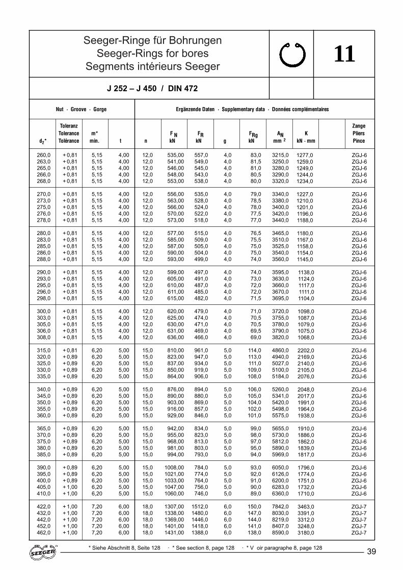
Seeger-Ringe für BohrungenSeeger-Rings for bores
Segments intérieurs Seeger
39
11
Nut · Groove · Gorge Ergänzende Daten · Supplementary data · Données complémentaires
Toleranz ZangeTolerance m* F N FR FRg AN K nabl. Pliers
d2* Tolérance min. t n kN kN g kN mm 2 kN · mm x1000 Pince
* Siehe Abschnitt 8, Seite 128 · * See section 8, page 128 · * V oir paragraphe 8, page 128
J 252 – J 450 / DIN 472
260,0 + 0,81 5,15 4,00 12,0 535,00 557,0 4,0 83,0 3215,0263,0 + 0,81 5,15 4,00 12,0 541,00 549,0 4,0 81,5 3250,0265,0 + 0,81 5,15 4,00 12,0 546,00 545,0 4,0 81,0 3280,0266,0 + 0,81 5,15 4,00 12,0 548,00 543,0 4,0 80,5 3290,0268,0 + 0,81 5,15 4,00 12,0 553,00 538,0 4,0 80,0 3320,0
270,0 + 0,81 5,15 4,00 12,0 556,00 535,0 4,0 79,0 3340,0273,0 + 0,81 5,15 4,00 12,0 563,00 528,0 4,0 78,5 3380,0275,0 + 0,81 5,15 4,00 12,0 566,00 524,0 4,0 78,0 3400,0276,0 + 0,81 5,15 4,00 12,0 570,00 522,0 4,0 77,5 3420,0278,0 + 0,81 5,15 4,00 12,0 573,00 518,0 4,0 77,0 3440,0
280,0 + 0,81 5,15 4,00 12,0 577,00 515,0 4,0 76,5 3465,0283,0 + 0,81 5,15 4,00 12,0 585,00 509,0 4,0 75,5 3510,0285,0 + 0,81 5,15 4,00 12,0 587,00 505,0 4,0 75,0 3525,0286,0 + 0,81 5,15 4,00 12,0 590,00 504,0 4,0 75,0 3540,0288,0 + 0,81 5,15 4,00 12,0 593,00 499,0 4,0 74,0 3560,0
290,0 + 0,81 5,15 4,00 12,0 599,00 497,0 4,0 74,0 3595,0293,0 + 0,81 5,15 4,00 12,0 605,00 491,0 4,0 73,0 3630,0295,0 + 0,81 5,15 4,00 12,0 610,00 487,0 4,0 72,0 3660,0296,0 + 0,81 5,15 4,00 12,0 611,00 485,0 4,0 72,0 3670,0298,0 + 0,81 5,15 4,00 12,0 615,00 482,0 4,0 71,5 3695,0
300,0 + 0,81 5,15 4,00 12,0 620,00 479,0 4,0 71,0 3720,0303,0 + 0,81 5,15 4,00 12,0 625,00 474,0 4,0 70,5 3755,0305,0 + 0,81 5,15 4,00 12,0 630,00 471,0 4,0 70,5 3780,0306,0 + 0,81 5,15 4,00 12,0 631,00 469,0 4,0 69,5 3790,0308,0 + 0,81 5,15 4,00 12,0 636,00 466,0 4,0 69,0 3820,0
315,0 + 0,81 6,20 5,00 15,0 810,00 961,0 5,0 114,0 4860,0320,0 + 0,89 6,20 5,00 15,0 823,00 947,0 5,0 113,0 4940,0325,0 + 0,89 6,20 5,00 15,0 837,00 934,0 5,0 111,0 5027,0330,0 + 0,89 6,20 5,00 15,0 850,00 919,0 5,0 109,0 5100,0335,0 + 0,89 6,20 5,00 15,0 864,00 906,0 5,0 108,0 5184,0
340,0 + 0,89 6,20 5,00 15,0 876,00 894,0 5,0 106,0 5260,0345,0 + 0,89 6,20 5,00 15,0 890,00 880,0 5,0 105,0 5341,0350,0 + 0,89 6,20 5,00 15,0 903,00 869,0 5,0 104,0 5420,0355,0 + 0,89 6,20 5,00 15,0 916,00 857,0 5,0 102,0 5498,0360,0 + 0,89 6,20 5,00 15,0 929,00 846,0 5,0 101,0 5575,0
365,0 + 0,89 6,20 5,00 15,0 942,00 834,0 5,0 99,0 5655,0370,0 + 0,89 6,20 5,00 15,0 955,00 823,0 5,0 98,0 5730,0375,0 + 0,89 6,20 5,00 15,0 968,00 813,0 5,0 97,0 5812,0380,0 + 0,89 6,20 5,00 15,0 981,00 803,0 5,0 95,0 5890,0385,0 + 0,89 6,20 5,00 15,0 994,00 793,0 5,0 94,0 5969,0
390,0 + 0,89 6,20 5,00 15,0 1008,00 784,0 5,0 93,0 6050,0395,0 + 0,89 6,20 5,00 15,0 1021,00 774,0 5,0 92,0 6126,0400,0 + 0,89 6,20 5,00 15,0 1033,00 764,0 5,0 91,0 6200,0405,0 + 1,00 6,20 5,00 15,0 1047,00 756,0 5,0 90,0 6283,0410,0 + 1,00 6,20 5,00 15,0 1060,00 746,0 5,0 89,0 6360,0
422,0 + 1,00 7,20 6,00 18,0 1307,00 1512,0 6,0 150,0 7842,0432,0 + 1,00 7,20 6,00 18,0 1338,00 1480,0 6,0 147,0 8030,0442,0 + 1,00 7,20 6,00 18,0 1369,00 1446,0 6,0 144,0 8219,0452,0 + 1,00 7,20 6,00 18,0 1401,00 1418,0 6,0 141,0 8407,0462,0 + 1,00 7,20 6,00 18,0 1431,00 1388,0 6,0 138,0 8590,0
1277,0 ZGJ-61259,0 ZGJ-61249,0 ZGJ-61244,0 ZGJ-61234,0 ZGJ-6
1227,0 ZGJ-61210,0 ZGJ-61201,0 ZGJ-61196,0 ZGJ-61188,0 ZGJ-6
1180,0 ZGJ-61167,0 ZGJ-61158,0 ZGJ-61154,0 ZGJ-61145,0 ZGJ-6
1138,0 ZGJ-61124,0 ZGJ-61117,0 ZGJ-61111,0 ZGJ-61104,0 ZGJ-6
1098,0 ZGJ-61087,0 ZGJ-61079,0 ZGJ-61075,0 ZGJ-61068,0 ZGJ-6
2202,0 ZGJ-62169,0 ZGJ-62140,0 ZGJ-62105,0 ZGJ-62076,0 ZGJ-6
2048,0 ZGJ-62017,0 ZGJ-61991,0 ZGJ-61964,0 ZGJ-61938,0 ZGJ-6
1910,0 ZGJ-61886,0 ZGJ-61862,0 ZGJ-61839,0 ZGJ-61817,0 ZGJ-6
1796,0 ZGJ-61774,0 ZGJ-61751,0 ZGJ-61732,0 ZGJ-61710,0 ZGJ-6
3463,0 ZGJ-73391,0 ZGJ-73312,0 ZGJ-73248,0 ZGJ-73180,0 ZGJ-7
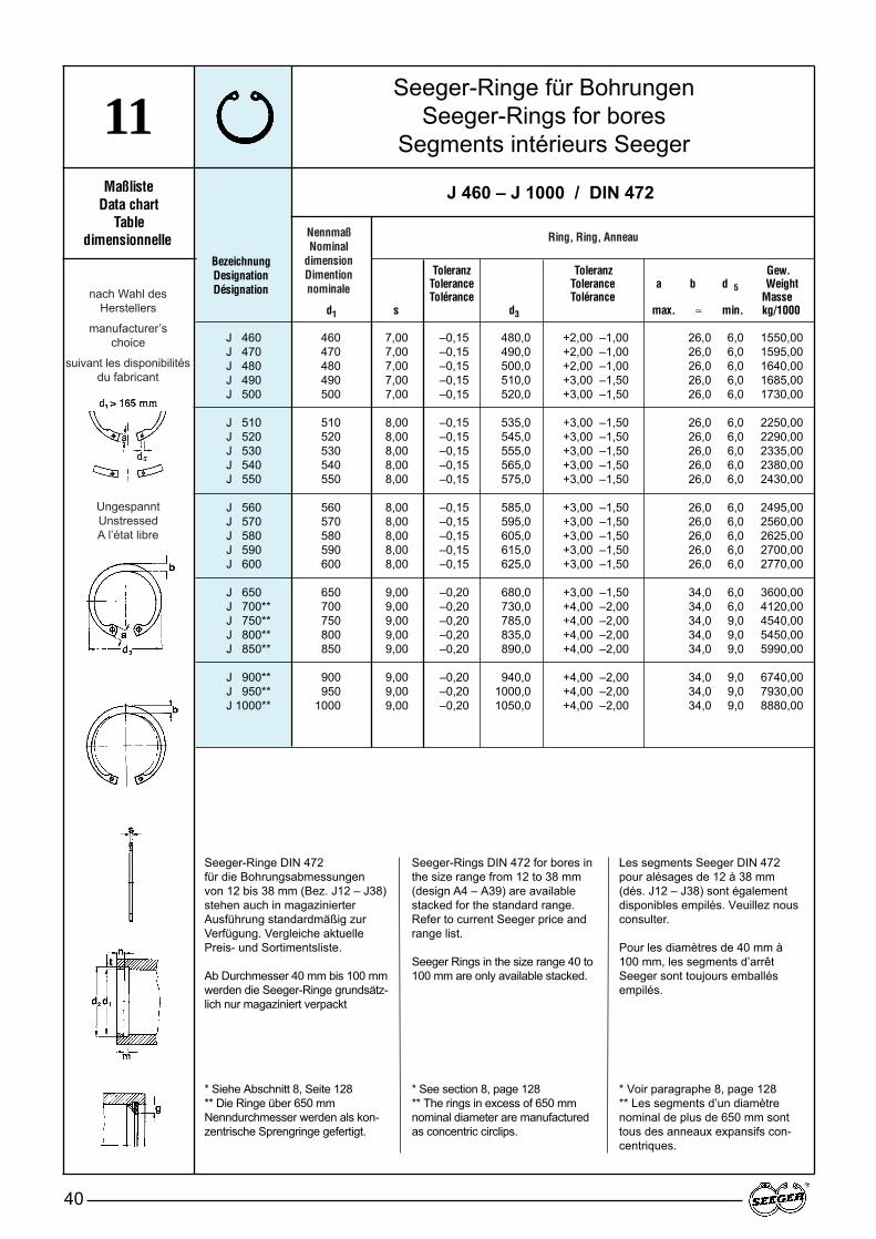
NennmaßNominal
dimensionDimention nominale
Ring, Ring, Anneau
UngespanntUnstressedA l’état libre
nach Wahl des Herstellers
manufacturer’s choice
suivant les disponibilitésdu fabricant
Seeger-Ringe für BohrungenSeeger-Rings for bores
Segments intérieurs Seeger
40
11Maßliste
Data chartTable
dimensionnelleBezeichnungDesignationDésignation
J 460 – J 1000 / DIN 472
J 460 460 7,00 –0,15 480,0 +2,00 –1,00 26,0 6,0 1550,00J 470 470 7,00 –0,15 490,0 +2,00 –1,00 26,0 6,0 1595,00J 480 480 7,00 –0,15 500,0 +2,00 –1,00 26,0 6,0 1640,00J 490 490 7,00 –0,15 510,0 +3,00 –1,50 26,0 6,0 1685,00J 500 500 7,00 –0,15 520,0 +3,00 –1,50 26,0 6,0 1730,00
J 510 510 8,00 –0,15 535,0 +3,00 –1,50 26,0 6,0 2250,00J 520 520 8,00 –0,15 545,0 +3,00 –1,50 26,0 6,0 2290,00J 530 530 8,00 –0,15 555,0 +3,00 –1,50 26,0 6,0 2335,00J 540 540 8,00 –0,15 565,0 +3,00 –1,50 26,0 6,0 2380,00J 550 550 8,00 –0,15 575,0 +3,00 –1,50 26,0 6,0 2430,00
J 560 560 8,00 –0,15 585,0 +3,00 –1,50 26,0 6,0 2495,00J 570 570 8,00 –0,15 595,0 +3,00 –1,50 26,0 6,0 2560,00J 580 580 8,00 –0,15 605,0 +3,00 –1,50 26,0 6,0 2625,00J 590 590 8,00 –0,15 615,0 +3,00 –1,50 26,0 6,0 2700,00J 600 600 8,00 –0,15 625,0 +3,00 –1,50 26,0 6,0 2770,00
J 650 650 9,00 –0,20 680,0 +3,00 –1,50 34,0 6,0 3600,00J 700** 700 9,00 –0,20 730,0 +4,00 –2,00 34,0 6,0 4120,00J 750** 750 9,00 –0,20 785,0 +4,00 –2,00 34,0 9,0 4540,00J 800** 800 9,00 –0,20 835,0 +4,00 –2,00 34,0 9,0 5450,00J 850** 850 9,00 –0,20 890,0 +4,00 –2,00 34,0 9,0 5990,00
J 900** 900 9,00 –0,20 940,0 +4,00 –2,00 34,0 9,0 6740,00J 950** 950 9,00 –0,20 1000,0 +4,00 –2,00 34,0 9,0 7930,00J 1000** 1000 9,00 –0,20 1050,0 +4,00 –2,00 34,0 9,0 8880,00
Seeger-Ringe DIN 472 für die Bohrungsabmessungen von 12 bis 38 mm (Bez. J12 – J38)stehen auch in magazinierterAusführung standardmäßig zurVerfügung. Vergleiche aktuellePreis- und Sortimentsliste.
Ab Durchmesser 40 mm bis 100 mmwerden die Seeger-Ringe grundsätz-lich nur magaziniert verpackt
* Siehe Abschnitt 8, Seite 128** Die Ringe über 650 mmNenndurchmesser werden als kon-zentrische Sprengringe gefertigt.
Seeger-Rings DIN 472 for bores inthe size range from 12 to 38 mm(design A4 – A39) are availablestacked for the standard range.Refer to current Seeger price andrange list.
Seeger Rings in the size range 40 to100 mm are only available stacked.
* See section 8, page 128** The rings in excess of 650 mmnominal diameter are manufacturedas concentric circlips.
Les segments Seeger DIN 472pour alésages de 12 à 38 mm(dés. J12 – J38) sont égalementdisponibles empilés. Veuillez nousconsulter.
Pour les diamètres de 40 mm à100 mm, les segments d’arrêtSeeger sont toujours emballésempilés.
* Voir paragraphe 8, page 128** Les segments d’un diamètrenominal de plus de 650 mm sonttous des anneaux expansifs con-centriques.
Toleranz Toleranz Gew.Tolerance Tolerance a b d 5 WeightTolérance Tolérance Masse
d1 s d3 max. ≈ min. kg/1000
Seeger-Ringe für BohrungenSeeger-Rings for bores
Segments intérieurs Seeger
41
11
Nut · Groove · Gorge Ergänzende Daten · Supplementary data · Données complémentaires
Toleranz ZangeTolerance m* F N FR FRg AN K nabl. Pliers
d2* Tolérance min. t n kN kN g kN mm 2 kN · mm x1000 Pince
* Siehe Abschnitt 8, Seite 128 · * See section 8, page 128 · * V oir paragraphe 8, page 128
J 460 – J 1000 / DIN 472
472,0 + 1,00 7,20 6,00 18,0 1464,00 1360,0 6,0 135,0 8784,0482,0 + 1,00 7,20 6,00 18,0 1495,00 1330,0 6,0 132,0 8973,0492,0 + 1,00 7,20 6,00 18,0 1526,00 1306,0 6,0 130,0 9161,0502,0 + 1,00 7,20 6,00 18,0 1558,00 1280,0 6,0 127,0 9349,0512,0 + 1,00 7,20 6,00 18,0 1588,00 1256,0 6,0 125,0 9530,0
524,0 + 1,00 8,20 7,00 21,0 1894,00 1834,0 7,0 156,0 11369,0534,0 + 1,00 8,20 7,00 21,0 1931,00 1802,0 7,0 153,0 11589,0544,0 + 1,00 8,20 7,00 21,0 1968,00 1768,0 7,0 150,0 11810,0554,0 + 1,00 8,20 7,00 21,0 2004,00 1738,0 7,0 148,0 12029,0564,0 + 1,00 8,20 7,00 21,0 2041,00 1711,0 7,0 145,0 12250,0
574,0 + 1,00 8,20 7,00 21,0 2078,00 1682,0 7,0 143,0 12469,0584,0 + 1,00 8,20 7,00 21,0 2114,00 1650,0 7,0 141,0 12689,0594,0 + 1,00 8,20 7,00 21,0 2151,00 1627,0 7,0 138,0 12909,0604,0 + 1,00 8,20 7,00 21,0 2188,00 1601,0 7,0 136,0 13129,0614,0 + 1,00 8,20 7,00 21,0 2221,00 1571,0 7,0 134,0 13330,0
666,0 + 1,00 9,30 8,00 24,0 2753,00 2654,0 7,0 226,0 16520,0716,0 + 1,00 9,30 8,00 24,0 2966,00 2471,0 7,0 210,0 17800,0768,0 + 1,00 9,30 9,00 27,0 3566,00 2310,0 7,0 196,0 21400,0818,0 + 1,00 9,30 9,00 27,0 3800,00 2176,0 7,0 184,0 22800,0870,0 + 1,00 9,30 10,00 30,0 4500,00 2045,0 7,0 173,0 27000,0
920,0 + 1,00 9,30 10,00 30,0 4766,00 1938,0 7,0 164,0 28600,0972,0 + 1,00 9,30 11,00 33,0 5608,00 1840,0 7,0 156,0 33650,0
1022,0 + 1,00 9,30 11,00 33,0 5825,00 1752,0 7,0 148,0 34950,0
3116,0 ZGJ-73048,0 ZGJ-72991,0 ZGJ-72931,0 ZGJ-72878,0 ZGJ-7
4201,0 ZGJ-74128,0 ZGJ-74049,0 ZGJ-73981,0 ZGJ-73919,0 ZGJ-7
3852,0 ZGJ-73790,0 ZGJ-73728,0 ZGJ-73668,0 ZGJ-73598,0 ZGJ-7
6078,0 ZGJ-75661,0 ZGJ-75285,0 ZGJ-74980,0 ZGJ-74680,0 ZGJ-7
4435,0 ZGJ-74210,0 ZGJ-74010,0 ZGJ-7
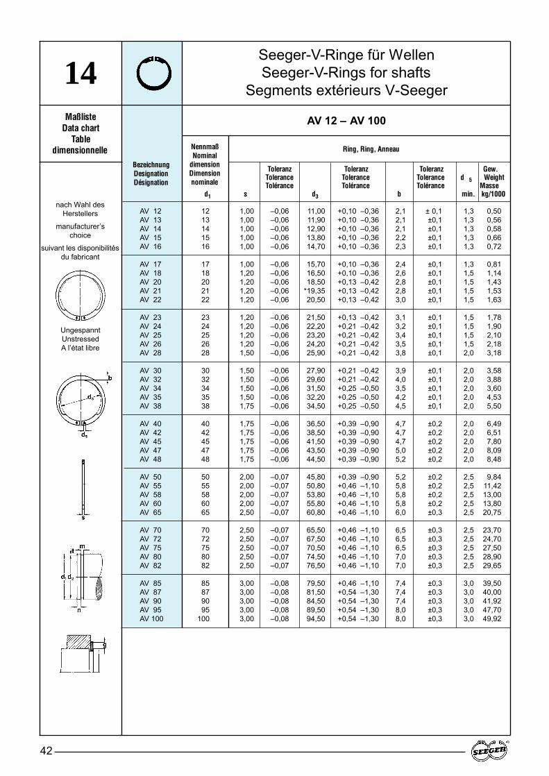
Seeger-V-Ringe für WellenSeeger-V-Rings for shafts
Segments extérieurs V-Seeger
42
14Maßliste
Data chartTable
dimensionnelle NennmaßNominal
dimensionDimension nominale
Toleranz Toleranz Toleranz Gew.Tolerance Tolerance Tolerance d 5 WeightTolérance Tolérance Tolérance Masse
d1 s d3 b min. kg/1000
BezeichnungDesignationDésignation
AV 12 – AV 100
Ring, Ring, Anneau
AV 12 12 1,00 –0,06 11,00 +0,10 –0,36 2,1 ± 0,1 1,3 0,50AV 13 13 1,00 –0,06 11,90 +0,10 –0,36 2,1 ±0,1 1,3 0,56AV 14 14 1,00 –0,06 12,90 +0,10 –0,36 2,1 ±0,1 1,3 0,58AV 15 15 1,00 –0,06 13,80 +0,10 –0,36 2,2 ±0,1 1,3 0,66AV 16 16 1,00 –0,06 14,70 +0,10 –0,36 2,3 ±0,1 1,3 0,72
AV 17 17 1,00 –0,06 15,70 +0,10 –0,36 2,4 ±0,1 1,3 0,81AV 18 18 1,20 –0,06 16,50 +0,10 –0,36 2,6 ±0,1 1,5 1,14AV 20 20 1,20 –0,06 18,50 +0,13 –0,42 2,8 ±0,1 1,5 1,43AV 21 21 1,20 –0,06 *19,35 +0,13 –0,42 2,8 ±0,1 1,5 1,53AV 22 22 1,20 –0,06 20,50 +0,13 –0,42 3,0 ±0,1 1,5 1,63
AV 23 23 1,20 –0,06 21,50 +0,13 –0,42 3,1 ±0,1 1,5 1,78AV 24 24 1,20 –0,06 22,20 +0,21 –0,42 3,2 ±0,1 1,5 1,90AV 25 25 1,20 –0,06 23,20 +0,21 –0,42 3,4 ±0,1 1,5 2,10AV 26 26 1,20 –0,06 24,20 +0,21 –0,42 3,5 ±0,1 1,5 2,18AV 28 28 1,50 –0,06 25,90 +0,21 –0,42 3,8 ±0,1 2,0 3,18
AV 30 30 1,50 –0,06 27,90 +0,21 –0,42 3,9 ±0,1 2,0 3,58AV 32 32 1,50 –0,06 29,60 +0,21 –0,42 4,0 ±0,1 2,0 3,88AV 34 34 1,50 –0,06 31,50 +0,25 –0,50 3,5 ±0,1 2,0 3,60AV 35 35 1,50 –0,06 32,20 +0,25 –0,50 4,2 ±0,1 2,0 4,53AV 38 38 1,75 –0,06 34,50 +0,25 –0,50 4,5 ±0,1 2,0 5,50
AV 40 40 1,75 –0,06 36,50 +0,39 –0,90 4,7 ±0,2 2,0 6,49AV 42 42 1,75 –0,06 38,50 +0,39 –0,90 4,7 ±0,2 2,0 6,51AV 45 45 1,75 –0,06 41,50 +0,39 –0,90 4,7 ±0,2 2,0 7,80AV 47 47 1,75 –0,06 43,50 +0,39 –0,90 5,0 ±0,2 2,0 8,09AV 48 48 1,75 –0,06 44,50 +0,39 –0,90 5,2 ±0,2 2,0 8,48
AV 50 50 2,00 –0,07 45,80 +0,39 –0,90 5,2 ±0,2 2,5 9,84AV 55 55 2,00 –0,07 50,80 +0,46 –1,10 5,8 ±0,2 2,5 11,42AV 58 58 2,00 –0,07 53,80 +0,46 –1,10 5,8 ±0,2 2,5 13,00AV 60 60 2,00 –0,07 55,80 +0,46 –1,10 5,8 ±0,2 2,5 13,80AV 65 65 2,50 –0,07 60,80 +0,46 –1,10 6,0 ±0,3 2,5 20,75
AV 70 70 2,50 –0,07 65,50 +0,46 –1,10 6,5 ±0,3 2,5 23,70AV 72 72 2,50 –0,07 67,50 +0,46 –1,10 6,5 ±0,3 2,5 24,70AV 75 75 2,50 –0,07 70,50 +0,46 –1,10 6,5 ±0,3 2,5 27,50AV 80 80 2,50 –0,07 74,50 +0,46 –1,10 7,0 ±0,3 2,5 28,90AV 82 82 2,50 –0,07 76,50 +0,46 –1,10 7,0 ±0,3 2,5 29,65
AV 85 85 3,00 –0,08 79,50 +0,46 –1,10 7,4 ±0,3 3,0 39,50AV 87 87 3,00 –0,08 81,50 +0,54 –1,30 7,4 ±0,3 3,0 40,00AV 90 90 3,00 –0,08 84,50 +0,54 –1,30 7,4 ±0,3 3,0 41,92AV 95 95 3,00 –0,08 89,50 +0,54 –1,30 8,0 ±0,3 3,0 47,70AV 100 100 3,00 –0,08 94,50 +0,54 –1,30 8,0 ±0,3 3,0 49,92
UngespanntUnstressedA l’état libre
nach Wahl des Herstellers
manufacturer’s choice
suivant les disponibilitésdu fabricant
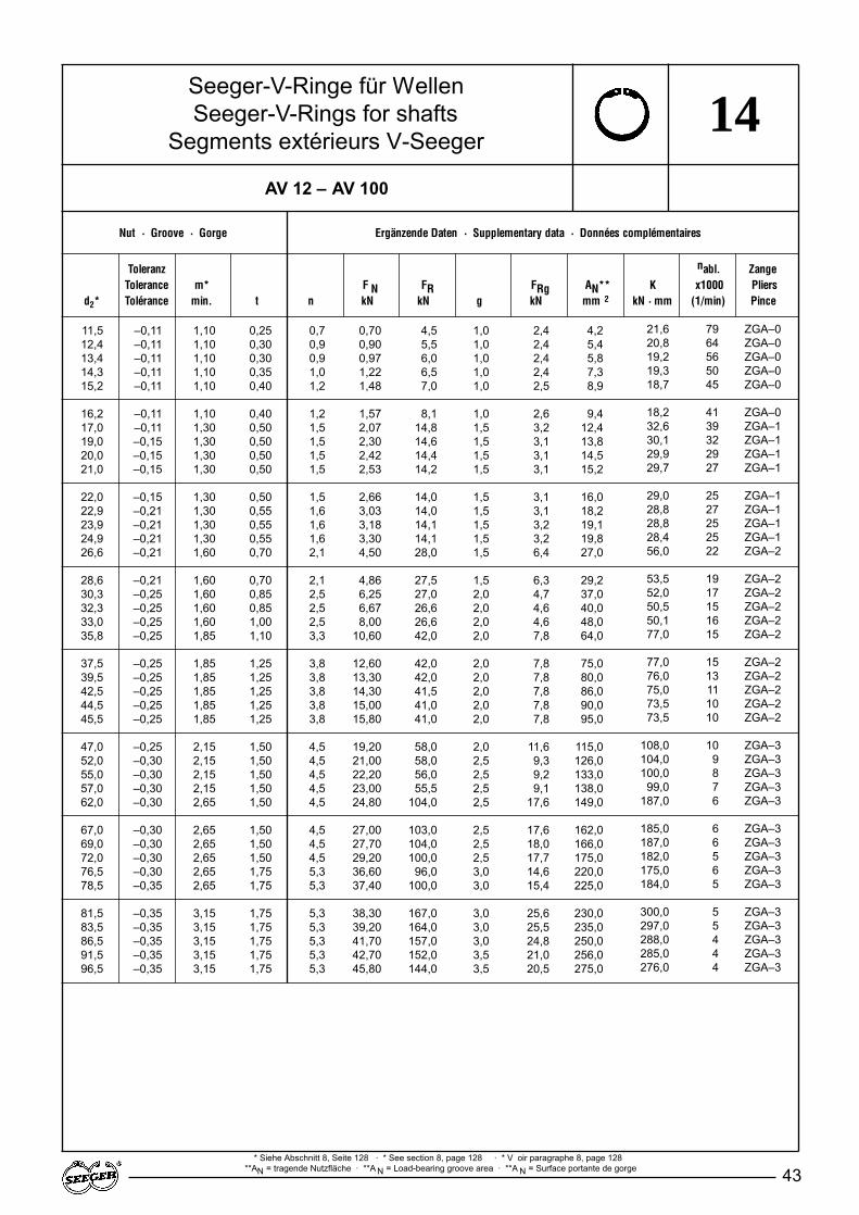
Seeger-V-Ringe für WellenSeeger-V-Rings for shafts
Segments extérieurs V-Seeger
43
14
Nut · Groove · Gorge Ergänzende Daten · Supplementary data · Données complémentaires
Toleranz nabl. ZangeTolerance m* F N FR FRg AN** K x1000 Pliers
d2* Tolérance min. t n kN kN g kN mm 2 kN · mm (1/min) Pince
* Siehe Abschnitt 8, Seite 128 · * See section 8, page 128 · * V oir paragraphe 8, page 128**AN = tragende Nutzfläche · **A N = Load-bearing groove area · **A N = Surface portante de gorge
AV 12 – AV 100
11,5 –0,11 1,10 0,25 0,7 0,70 4,5 1,0 2,4 4,212,4 –0,11 1,10 0,30 0,9 0,90 5,5 1,0 2,4 5,413,4 –0,11 1,10 0,30 0,9 0,97 6,0 1,0 2,4 5,814,3 –0,11 1,10 0,35 1,0 1,22 6,5 1,0 2,4 7,315,2 –0,11 1,10 0,40 1,2 1,48 7,0 1,0 2,5 8,9
16,2 –0,11 1,10 0,40 1,2 1,57 8,1 1,0 2,6 9,417,0 –0,11 1,30 0,50 1,5 2,07 14,8 1,5 3,2 12,419,0 –0,15 1,30 0,50 1,5 2,30 14,6 1,5 3,1 13,820,0 –0,15 1,30 0,50 1,5 2,42 14,4 1,5 3,1 14,521,0 –0,15 1,30 0,50 1,5 2,53 14,2 1,5 3,1 15,2
22,0 –0,15 1,30 0,50 1,5 2,66 14,0 1,5 3,1 16,022,9 –0,21 1,30 0,55 1,6 3,03 14,0 1,5 3,1 18,223,9 –0,21 1,30 0,55 1,6 3,18 14,1 1,5 3,2 19,124,9 –0,21 1,30 0,55 1,6 3,30 14,1 1,5 3,2 19,826,6 –0,21 1,60 0,70 2,1 4,50 28,0 1,5 6,4 27,0
28,6 –0,21 1,60 0,70 2,1 4,86 27,5 1,5 6,3 29,230,3 –0,25 1,60 0,85 2,5 6,25 27,0 2,0 4,7 37,032,3 –0,25 1,60 0,85 2,5 6,67 26,6 2,0 4,6 40,033,0 –0,25 1,60 1,00 2,5 8,00 26,6 2,0 4,6 48,035,8 –0,25 1,85 1,10 3,3 10,60 42,0 2,0 7,8 64,0
37,5 –0,25 1,85 1,25 3,8 12,60 42,0 2,0 7,8 75,039,5 –0,25 1,85 1,25 3,8 13,30 42,0 2,0 7,8 80,042,5 –0,25 1,85 1,25 3,8 14,30 41,5 2,0 7,8 86,044,5 –0,25 1,85 1,25 3,8 15,00 41,0 2,0 7,8 90,045,5 –0,25 1,85 1,25 3,8 15,80 41,0 2,0 7,8 95,0
47,0 –0,25 2,15 1,50 4,5 19,20 58,0 2,0 11,6 115,052,0 –0,30 2,15 1,50 4,5 21,00 58,0 2,5 9,3 126,055,0 –0,30 2,15 1,50 4,5 22,20 56,0 2,5 9,2 133,057,0 –0,30 2,15 1,50 4,5 23,00 55,5 2,5 9,1 138,062,0 –0,30 2,65 1,50 4,5 24,80 104,0 2,5 17,6 149,0
67,0 –0,30 2,65 1,50 4,5 27,00 103,0 2,5 17,6 162,069,0 –0,30 2,65 1,50 4,5 27,70 104,0 2,5 18,0 166,072,0 –0,30 2,65 1,50 4,5 29,20 100,0 2,5 17,7 175,076,5 –0,30 2,65 1,75 5,3 36,60 96,0 3,0 14,6 220,078,5 –0,35 2,65 1,75 5,3 37,40 100,0 3,0 15,4 225,0
81,5 –0,35 3,15 1,75 5,3 38,30 167,0 3,0 25,6 230,083,5 –0,35 3,15 1,75 5,3 39,20 164,0 3,0 25,5 235,086,5 –0,35 3,15 1,75 5,3 41,70 157,0 3,0 24,8 250,091,5 –0,35 3,15 1,75 5,3 42,70 152,0 3,5 21,0 256,096,5 –0,35 3,15 1,75 5,3 45,80 144,0 3,5 20,5 275,0
21,6 79 ZGA–020,8 64 ZGA–019,2 56 ZGA–019,3 50 ZGA–018,7 45 ZGA–0
18,2 41 ZGA–032,6 39 ZGA–130,1 32 ZGA–129,9 29 ZGA–129,7 27 ZGA–1
29,0 25 ZGA–128,8 27 ZGA–128,8 25 ZGA–128,4 25 ZGA–156,0 22 ZGA–2
53,5 19 ZGA–252,0 17 ZGA–250,5 15 ZGA–250,1 16 ZGA–277,0 15 ZGA–2
77,0 15 ZGA–276,0 13 ZGA–275,0 11 ZGA–273,5 10 ZGA–273,5 10 ZGA–2
108,0 10 ZGA–3104,0 9 ZGA–3100,0 8 ZGA–399,0 7 ZGA–3
187,0 6 ZGA–3
185,0 6 ZGA–3187,0 6 ZGA–3182,0 5 ZGA–3175,0 6 ZGA–3184,0 5 ZGA–3
300,0 5 ZGA–3297,0 5 ZGA–3288,0 4 ZGA–3285,0 4 ZGA–3276,0 4 ZGA–3
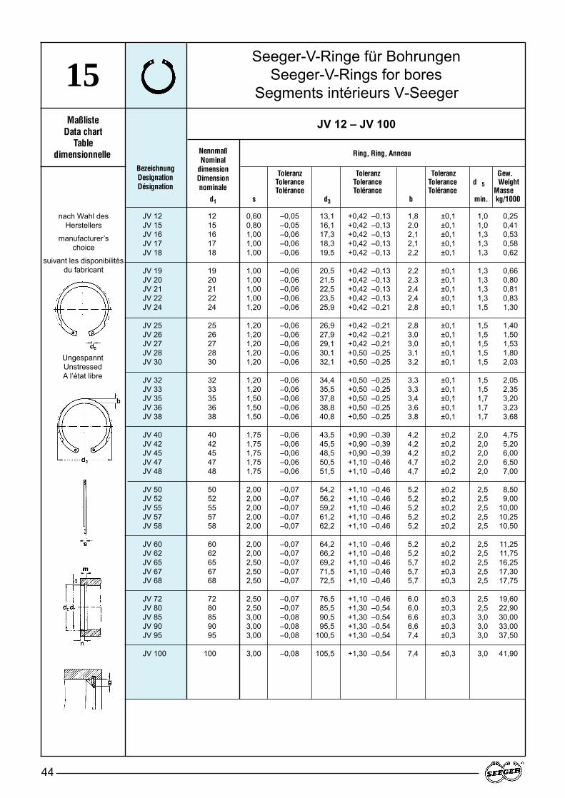
Seeger-V-Ringe für BohrungenSeeger-V-Rings for bores
Segments intérieurs V-Seeger
44
15Maßliste
Data chartTable
dimensionnelle NennmaßNominal
dimensionDimension nominale
Toleranz Toleranz Toleranz Gew.Tolerance Tolerance Tolerance d 5 WeightTolérance Tolérance Tolérance Masse
d1 s d3 b min. kg/1000
BezeichnungDesignationDésignation
JV 12 – JV 100
Ring, Ring, Anneau
JV 12 12 0,60 –0,05 13,1 +0,42 –0,13 1,8 ±0,1 1,0 0,25JV 15 15 0,80 –0,05 16,1 +0,42 –0,13 2,0 ±0,1 1,0 0,41JV 16 16 1,00 –0,06 17,3 +0,42 –0,13 2,1 ±0,1 1,3 0,53JV 17 17 1,00 –0,06 18,3 +0,42 –0,13 2,1 ±0,1 1,3 0,58JV 18 18 1,00 –0,06 19,5 +0,42 –0,13 2,2 ±0,1 1,3 0,62
JV 19 19 1,00 –0,06 20,5 +0,42 –0,13 2,2 ±0,1 1,3 0,66JV 20 20 1,00 –0,06 21,5 +0,42 –0,13 2,3 ±0,1 1,3 0,80JV 21 21 1,00 –0,06 22,5 +0,42 –0,13 2,4 ±0,1 1,3 0,81JV 22 22 1,00 –0,06 23,5 +0,42 –0,13 2,4 ±0,1 1,3 0,83JV 24 24 1,20 –0,06 25,9 +0,42 –0,21 2,8 ±0,1 1,5 1,30
JV 25 25 1,20 –0,06 26,9 +0,42 –0,21 2,8 ±0,1 1,5 1,40JV 26 26 1,20 –0,06 27,9 +0,42 –0,21 3,0 ±0,1 1,5 1,50JV 27 27 1,20 –0,06 29,1 +0,42 –0,21 3,0 ±0,1 1,5 1,53JV 28 28 1,20 –0,06 30,1 +0,50 –0,25 3,1 ±0,1 1,5 1,80JV 30 30 1,20 –0,06 32,1 +0,50 –0,25 3,2 ±0,1 1,5 2,03
JV 32 32 1,20 –0,06 34,4 +0,50 –0,25 3,3 ±0,1 1,5 2,05JV 33 33 1,20 –0,06 35,5 +0,50 –0,25 3,3 ±0,1 1,5 2,35JV 35 35 1,50 –0,06 37,8 +0,50 –0,25 3,4 ±0,1 1,7 3,20JV 36 36 1,50 –0,06 38,8 +0,50 –0,25 3,6 ±0,1 1,7 3,23JV 38 38 1,50 –0,06 40,8 +0,50 –0,25 3,8 ±0,1 1,7 3,68
JV 40 40 1,75 –0,06 43,5 +0,90 –0,39 4,2 ±0,2 2,0 4,75JV 42 42 1,75 –0,06 45,5 +0,90 –0,39 4,2 ±0,2 2,0 5,20JV 45 45 1,75 –0,06 48,5 +0,90 –0,39 4,2 ±0,2 2,0 6,00JV 47 47 1,75 –0,06 50,5 +1,10 –0,46 4,7 ±0,2 2,0 6,50JV 48 48 1,75 –0,06 51,5 +1,10 –0,46 4,7 ±0,2 2,0 7,00
JV 50 50 2,00 –0,07 54,2 +1,10 –0,46 5,2 ±0,2 2,5 8,50JV 52 52 2,00 –0,07 56,2 +1,10 –0,46 5,2 ±0,2 2,5 9,00JV 55 55 2,00 –0,07 59,2 +1,10 –0,46 5,2 ±0,2 2,5 10,00JV 57 57 2,00 –0,07 61,2 +1,10 –0,46 5,2 ±0,2 2,5 10,25JV 58 58 2,00 –0,07 62,2 +1,10 –0,46 5,2 ±0,2 2,5 10,50
JV 60 60 2,00 –0,07 64,2 +1,10 –0,46 5,2 ±0,2 2,5 11,25JV 62 62 2,00 –0,07 66,2 +1,10 –0,46 5,2 ±0,2 2,5 11,75JV 65 65 2,50 –0,07 69,2 +1,10 –0,46 5,7 ±0,2 2,5 16,25JV 67 67 2,50 –0,07 71,5 +1,10 –0,46 5,7 ±0,3 2,5 17,30JV 68 68 2,50 –0,07 72,5 +1,10 –0,46 5,7 ±0,3 2,5 17,75
JV 72 72 2,50 –0,07 76,5 +1,10 –0,46 6,0 ±0,3 2,5 19,60JV 80 80 2,50 –0,07 85,5 +1,30 –0,54 6,0 ±0,3 2,5 22,90JV 85 85 3,00 –0,08 90,5 +1,30 –0,54 6,6 ±0,3 3,0 30,00JV 90 90 3,00 –0,08 95,5 +1,30 –0,54 6,6 ±0,3 3,0 33,00JV 95 95 3,00 –0,08 100,5 +1,30 –0,54 7,4 ±0,3 3,0 37,50
JV 100 100 3,00 –0,08 105,5 +1,30 –0,54 7,4 ±0,3 3,0 41,90
UngespanntUnstressedA l’état libre
nach Wahl des Herstellers
manufacturer’s choice
suivant les disponibilitésdu fabricant

Seeger-V-Ringe für BohrungenSeeger-V-Rings for bores
Segments intérieurs V-Seeger
45
15
Nut · Groove · Gorge Ergänzende Daten · Supplementary data · Données complémentaires
Toleranz ZangeTolerance m* F N FR FRg AN** K nabl. Pliers
d2* Tolérance min. t n kN kN g kN mm 2 kN · mm x1000 Pince
* Siehe Abschnitt 8, Seite 128 · * See section 8, page 128 · * V oir paragraphe 8, page 128**AN = tragende Nutzfläche · **A N = Load-bearing groove area · **A N = Surface portante de gorge
JV 12 – JV 100
12,6 + 0,11 0,70 0,30 0,9 0,75 1,8 0,8 1,0 4,515,7 + 0,11 0,90 0,35 1,0 1,33 3,3 1,0 1,9 8,016,8 + 0,11 1,10 0,40 1,2 1,67 5,2 1,0 3,1 10,017,8 + 0,11 1,10 0,40 1,2 1,70 5,8 1,0 3,0 11,019,0 + 0,15 1,10 0,50 1,5 1,78 6,3 1,0 3,0 14,0
20,0 + 0,15 1,10 0,50 1,5 2,50 6,6 1,0 2,8 15,021,0 + 0,15 1,10 0,50 1,5 2,66 7,0 1,0 2,9 16,022,0 + 0,15 1,10 0,50 1,5 2,73 7,4 1,0 2,8 17,023,0 + 0,15 1,10 0,50 1,5 2,80 7,5 1,0 2,8 17,025,2 + 0,21 1,30 0,60 1,8 3,68 14,5 1,0 4,8 22,0
26,2 + 0,21 1,30 0,60 1,8 4,00 14,8 1,0 5,0 24,027,2 + 0,21 1,30 0,60 1,8 4,17 15,3 1,0 5,2 25,028,4 + 0,21 1,30 0,70 2,1 5,00 15,0 1,0 5,1 30,029,4 + 0,21 1,30 0,70 2,1 5,10 15,3 1,0 5,2 31,031,4 + 0,25 1,30 0,70 2,1 5,50 14,9 1,0 5,1 33,0
33,7 + 0,25 1,30 0,85 2,5 7,00 14,1 1,0 4,9 42,034,7 + 0,25 1,30 0,85 2,5 7,30 13,8 1,0 4,8 44,037,0 + 0,25 1,60 1,00 3,0 9,20 26,4 1,5 6,3 55,038,0 + 0,25 1,60 1,00 3,0 9,70 27,5 1,5 6,6 58,040,0 + 0,25 1,60 1,00 3,0 10,20 28,0 1,5 6,7 61,0
42,5 + 0,25 1,85 1,25 3,8 13,50 45,5 2,0 8,4 81,044,5 + 0,25 1,85 1,25 3,8 14,10 45,5 2,0 8,5 85,047,5 + 0,25 1,85 1,25 3,8 15,00 44,0 2,0 8,4 90,049,5 + 0,25 1,85 1,25 3,8 15,80 45,0 2,0 8,7 95,050,5 + 0,30 1,85 1,25 3,8 16,00 48,0 2,0 9,1 96,0
53,0 + 0,30 2,15 1,50 4,5 20,00 69,0 2,0 13,4 120,055,0 + 0,30 2,15 1,50 4,5 20,80 66,5 2,0 13,3 125,058,0 + 0,30 2,15 1,50 4,5 22,20 66,0 2,0 13,3 133,060,0 + 0,30 2,15 1,50 4,5 23,00 65,0 2,0 13,1 138,061,0 + 0,30 2,15 1,50 4,5 23,30 64,0 2,0 12,9 140,0
63,0 + 0,30 2,15 1,50 4,5 24,20 62,0 2,0 12,7 145,065,0 + 0,30 2,15 1,50 4,5 25,00 60,0 2,0 12,3 150,068,0 + 0,30 2,65 1,50 4,5 25,80 122,0 2,5 20,6 155,070,0 + 0,30 2,65 1,50 4,5 26,80 122,0 2,5 20,8 161,071,0 + 0,30 2,65 1,50 4,5 27,20 123,0 2,5 21,0 163,0
75,0 + 0,30 2,65 1,50 4,5 28,80 119,0 2,5 20,8 173,083,5 + 0,35 2,65 1,75 5,3 37,40 110,0 2,5 19,6 224,088,5 + 0,35 3,15 1,75 5,3 39,70 176,0 3,0 27,2 238,093,5 + 0,35 3,15 1,75 5,3 42,00 169,0 3,0 26,6 252,098,5 + 0,35 3,15 1,75 5,3 43,50 168,0 3,0 27,0 261,0
103,5 + 0,35 3,15 1,75 5,3 46,70 165,0 3,0 26,8 280,0
5,5 ZGJ–011,0 ZGJ–022,7 ZGJ–121,2 ZGJ–120,4 ZGJ–1
19,2 ZGJ–119,0 ZGJ–118,5 ZGJ–117,8 ZGJ–129,9 ZGJ–1
30,6 ZGJ–131,4 ZGJ–129,9 ZGJ–130,4 ZGJ–129,0 ZGJ–1
27,4 ZGJ–126,6 ZGJ–149,6 ZGJ–151,5 ZGJ–151,2 ZGJ–1
82,5 ZGJ–282,5 ZGJ–279,5 ZGJ–281,3 ZGJ–285,8 ZGJ–2
124,0 ZGJ–3121,0 ZGJ–3118,0 ZGJ–3115,0 ZGJ–3113,0 ZGJ–3
111,0 ZGJ–3107,0 ZGJ–3218,0 ZGJ–3218,0 ZGJ–3220,0 ZGJ–3
214,0 ZGJ–3196,0 ZGJ–3318,0 ZGJ–3309,0 ZGJ–3315,0 ZGJ–3
312,0 ZGJ–3
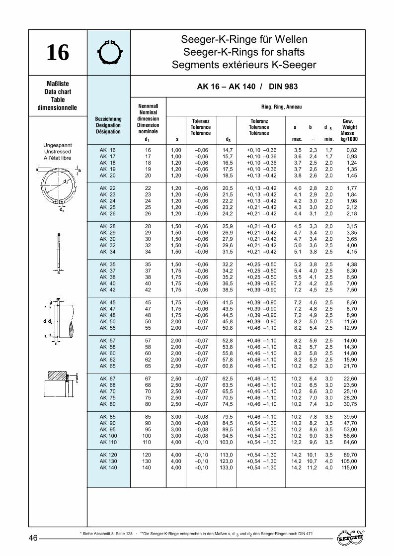
* Siehe Abschnitt 8, Seite 128 · **Die Seeger-K-Ringe entsprechen in den Maßen s, d 3 und d2 den Seeger-Ringen nach DIN 47146
16Maßliste
Data chartTable
dimensionnelle NennmaßNominal
dimensionDimension nominale
BezeichnungDesignationDésignation
Ring, Ring, Anneau
Seeger-K-Ringe für WellenSeeger-K-Rings for shafts
Segments extérieurs K-Seeger
AK 16 – AK 140 / DIN 983
AK 16 16 1,00 –0,06 14,7 +0,10 –0,36 3,5 2,3 1,7 0,82AK 17 17 1,00 –0,06 15,7 +0,10 –0,36 3,6 2,4 1,7 0,93AK 18 18 1,20 –0,06 16,5 +0,10 –0,36 3,7 2,5 2,0 1,24AK 19 19 1,20 –0,06 17,5 +0,10 –0,36 3,7 2,6 2,0 1,35AK 20 20 1,20 –0,06 18,5 +0,13 –0,42 3,8 2,6 2,0 1,45
AK 22 22 1,20 –0,06 20,5 +0,13 –0,42 4,0 2,8 2,0 1,77AK 23 23 1,20 –0,06 21,5 +0,13 –0,42 4,1 2,9 2,0 1,84AK 24 24 1,20 –0,06 22,2 +0,13 –0,42 4,2 3,0 2,0 1,98AK 25 25 1,20 –0,06 23,2 +0,21 –0,42 4,3 3,0 2,0 2,12AK 26 26 1,20 –0,06 24,2 +0,21 –0,42 4,4 3,1 2,0 2,18
AK 28 28 1,50 –0,06 25,9 +0,21 –0,42 4,5 3,3 2,0 3,15AK 29 29 1,50 –0,06 26,9 +0,21 –0,42 4,7 3,4 2,0 3,35AK 30 30 1,50 –0,06 27,9 +0,21 –0,42 4,7 3,4 2,0 3,65AK 32 32 1,50 –0,06 29,6 +0,21 –0,42 5,0 3,6 2,5 4,00AK 34 34 1,50 –0,06 31,5 +0,21 –0,42 5,1 3,8 2,5 4,15
AK 35 35 1,50 –0,06 32,2 +0,25 –0,50 5,2 3,8 2,5 4,38AK 37 37 1,75 –0,06 34,2 +0,25 –0,50 5,4 4,0 2,5 6,30AK 38 38 1,75 –0,06 35,2 +0,25 –0,50 5,5 4,1 2,5 6,50AK 40 40 1,75 –0,06 36,5 +0,39 –0,90 7,2 4,2 2,5 7,00AK 42 42 1,75 –0,06 38,5 +0,39 –0,90 7,2 4,5 2,5 7,50
AK 45 45 1,75 –0,06 41,5 +0,39 –0,90 7,2 4,6 2,5 8,50AK 47 47 1,75 –0,06 43,5 +0,39 –0,90 7,2 4,8 2,5 8,70AK 48 48 1,75 –0,06 44,5 +0,39 –0,90 7,2 4,9 2,5 8,90AK 50 50 2,00 –0,07 45,8 +0,39 –0,90 8,2 5,0 2,5 11,50AK 55 55 2,00 –0,07 50,8 +0,46 –1,10 8,2 5,4 2,5 12,99
AK 57 57 2,00 –0,07 52,8 +0,46 –1,10 8,2 5,6 2,5 14,00AK 58 58 2,00 –0,07 53,8 +0,46 –1,10 8,2 5,7 2,5 14,30AK 60 60 2,00 –0,07 55,8 +0,46 –1,10 8,2 5,8 2,5 14,80AK 62 62 2,00 –0,07 57,8 +0,46 –1,10 8,2 5,9 2,5 15,90AK 65 65 2,50 –0,07 60,8 +0,46 –1,10 10,2 6,2 3,0 21,70
AK 67 67 2,50 –0,07 62,5 +0,46 –1,10 10,2 6,4 3,0 22,60AK 68 68 2,50 –0,07 63,5 +0,46 –1,10 10,2 6,5 3,0 23,50AK 70 70 2,50 –0,07 65,5 +0,46 –1,10 10,2 6,6 3,0 25,10AK 75 75 2,50 –0,07 70,5 +0,46 –1,10 10,2 7,0 3,0 28,20AK 80 80 2,50 –0,07 74,5 +0,46 –1,10 10,2 7,4 3,0 30,75
AK 85 85 3,00 –0,08 79,5 +0,46 –1,10 10,2 7,8 3,5 39,50AK 90 90 3,00 –0,08 84,5 +0,54 –1,30 10,2 8,2 3,5 47,70AK 95 95 3,00 –0,08 89,5 +0,54 –1,30 10,2 8,6 3,5 53,00AK 100 100 3,00 –0,08 94,5 +0,54 –1,30 10,2 9,0 3,5 56,60AK 110 110 4,00 –0,10 103,0 +0,54 –1,30 12,2 9,6 3,5 84,60
AK 120 120 4,00 –0,10 113,0 +0,54 –1,30 14,2 10,1 3,5 89,70AK 130 130 4,00 –0,10 123,0 +0,54 –1,30 14,2 10,7 4,0 105,00AK 140 140 4,00 –0,10 133,0 +0,54 –1,30 14,2 11,2 4,0 115,00
UngespanntUnstressedA l’état libre
Toleranz Toleranz Gew.Tolerance Tolerance a b d 5 WeightTolérance Tolérance Masse
d1 s d3 max. ≈ min. kg/1000
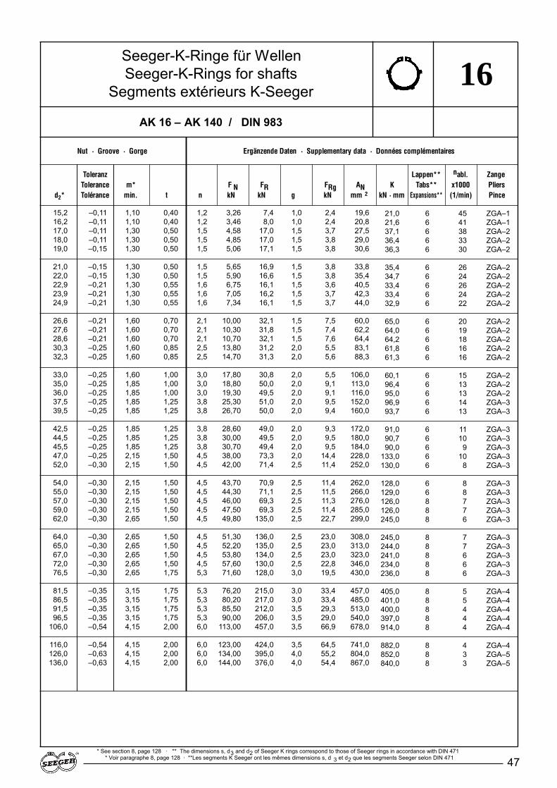
47
Nut · Groove · Gorge Ergänzende Daten · Supplementary data · Données complémentaires
Toleranz Lappen** nabl. ZangeTolerance m* F N FR FRg AN K Tabs** x1000 Pliers
d2* Tolérance min. t n kN kN g kN mm 2 kN · mm Expansions** (1/min) Pince
* See section 8, page 128 · ** The dimensions s, d3 and d2 of Seeger K rings correspond to those of Seeger rings in accordance with DIN 471* Voir paragraphe 8, page 128 · **Les segments K Seeger ont les mêmes dimensions s, d 3 et d2 que les segments Seeger selon DIN 471
AK 16 – AK 140 / DIN 983
Seeger-K-Ringe für WellenSeeger-K-Rings for shafts
Segments extérieurs K-Seeger16
15,2 –0,11 1,10 0,40 1,2 3,26 7,4 1,0 2,4 19,616,2 –0,11 1,10 0,40 1,2 3,46 8,0 1,0 2,4 20,817,0 –0,11 1,30 0,50 1,5 4,58 17,0 1,5 3,7 27,518,0 –0,11 1,30 0,50 1,5 4,85 17,0 1,5 3,8 29,019,0 –0,15 1,30 0,50 1,5 5,06 17,1 1,5 3,8 30,6
21,0 –0,15 1,30 0,50 1,5 5,65 16,9 1,5 3,8 33,822,0 –0,15 1,30 0,50 1,5 5,90 16,6 1,5 3,8 35,422,9 –0,21 1,30 0,55 1,6 6,75 16,1 1,5 3,6 40,523,9 –0,21 1,30 0,55 1,6 7,05 16,2 1,5 3,7 42,324,9 –0,21 1,30 0,55 1,6 7,34 16,1 1,5 3,7 44,0
26,6 –0,21 1,60 0,70 2,1 10,00 32,1 1,5 7,5 60,027,6 –0,21 1,60 0,70 2,1 10,30 31,8 1,5 7,4 62,228,6 –0,21 1,60 0,70 2,1 10,70 32,1 1,5 7,6 64,430,3 –0,25 1,60 0,85 2,5 13,80 31,2 2,0 5,5 83,132,3 –0,25 1,60 0,85 2,5 14,70 31,3 2,0 5,6 88,3
33,0 –0,25 1,60 1,00 3,0 17,80 30,8 2,0 5,5 106,035,0 –0,25 1,85 1,00 3,0 18,80 50,0 2,0 9,1 113,036,0 –0,25 1,85 1,00 3,0 19,30 49,5 2,0 9,1 116,037,5 –0,25 1,85 1,25 3,8 25,30 51,0 2,0 9,5 152,039,5 –0,25 1,85 1,25 3,8 26,70 50,0 2,0 9,4 160,0
42,5 –0,25 1,85 1,25 3,8 28,60 49,0 2,0 9,3 172,044,5 –0,25 1,85 1,25 3,8 30,00 49,5 2,0 9,5 180,045,5 –0,25 1,85 1,25 3,8 30,70 49,4 2,0 9,5 184,047,0 –0,25 2,15 1,50 4,5 38,00 73,3 2,0 14,4 228,052,0 –0,30 2,15 1,50 4,5 42,00 71,4 2,5 11,4 252,0
54,0 –0,30 2,15 1,50 4,5 43,70 70,9 2,5 11,4 262,055,0 –0,30 2,15 1,50 4,5 44,30 71,1 2,5 11,5 266,057,0 –0,30 2,15 1,50 4,5 46,00 69,3 2,5 11,3 276,059,0 –0,30 2,15 1,50 4,5 47,50 69,3 2,5 11,4 285,062,0 –0,30 2,65 1,50 4,5 49,80 135,0 2,5 22,7 299,0
64,0 –0,30 2,65 1,50 4,5 51,30 136,0 2,5 23,0 308,065,0 –0,30 2,65 1,50 4,5 52,20 135,0 2,5 23,0 313,067,0 –0,30 2,65 1,50 4,5 53,80 134,0 2,5 23,0 323,072,0 –0,30 2,65 1,50 4,5 57,60 130,0 2,5 22,8 346,076,5 –0,30 2,65 1,75 5,3 71,60 128,0 3,0 19,5 430,0
81,5 –0,35 3,15 1,75 5,3 76,20 215,0 3,0 33,4 457,086,5 –0,35 3,15 1,75 5,3 80,20 217,0 3,0 33,4 485,091,5 –0,35 3,15 1,75 5,3 85,50 212,0 3,5 29,3 513,096,5 –0,35 3,15 1,75 5,3 90,00 206,0 3,5 29,0 540,0
106,0 –0,54 4,15 2,00 6,0 113,00 457,0 3,5 66,9 678,0
116,0 –0,54 4,15 2,00 6,0 123,00 424,0 3,5 64,5 741,0126,0 –0,63 4,15 2,00 6,0 134,00 395,0 4,0 55,2 804,0136,0 –0,63 4,15 2,00 6,0 144,00 376,0 4,0 54,4 867,0
21,0 6 45 ZGA–121,6 6 41 ZGA–137,1 6 38 ZGA–236,4 6 33 ZGA–236,3 6 30 ZGA–2
35,4 6 26 ZGA–234,7 6 24 ZGA–233,4 6 26 ZGA–233,4 6 24 ZGA–232,9 6 22 ZGA–2
65,0 6 20 ZGA–264,0 6 19 ZGA–264,2 6 18 ZGA–261,8 6 16 ZGA–261,3 6 16 ZGA–2
60,1 6 15 ZGA–296,4 6 13 ZGA–295,0 6 13 ZGA–296,9 6 14 ZGA–393,7 6 13 ZGA–3
91,0 6 11 ZGA–390,7 6 10 ZGA–390,0 6 9 ZGA–3
133,0 6 10 ZGA–3130,0 6 8 ZGA–3
128,0 6 8 ZGA–3129,0 6 8 ZGA–3126,0 8 7 ZGA–3126,0 8 7 ZGA–3245,0 8 6 ZGA–3
245,0 8 7 ZGA–3244,0 8 7 ZGA–3241,0 8 6 ZGA–3234,0 8 6 ZGA–3236,0 8 6 ZGA–3
405,0 8 5 ZGA–4401,0 8 5 ZGA–4400,0 8 4 ZGA–4397,0 8 4 ZGA–4914,0 8 4 ZGA–4
882,0 8 4 ZGA–4852,0 8 3 ZGA–5840,0 8 3 ZGA–5
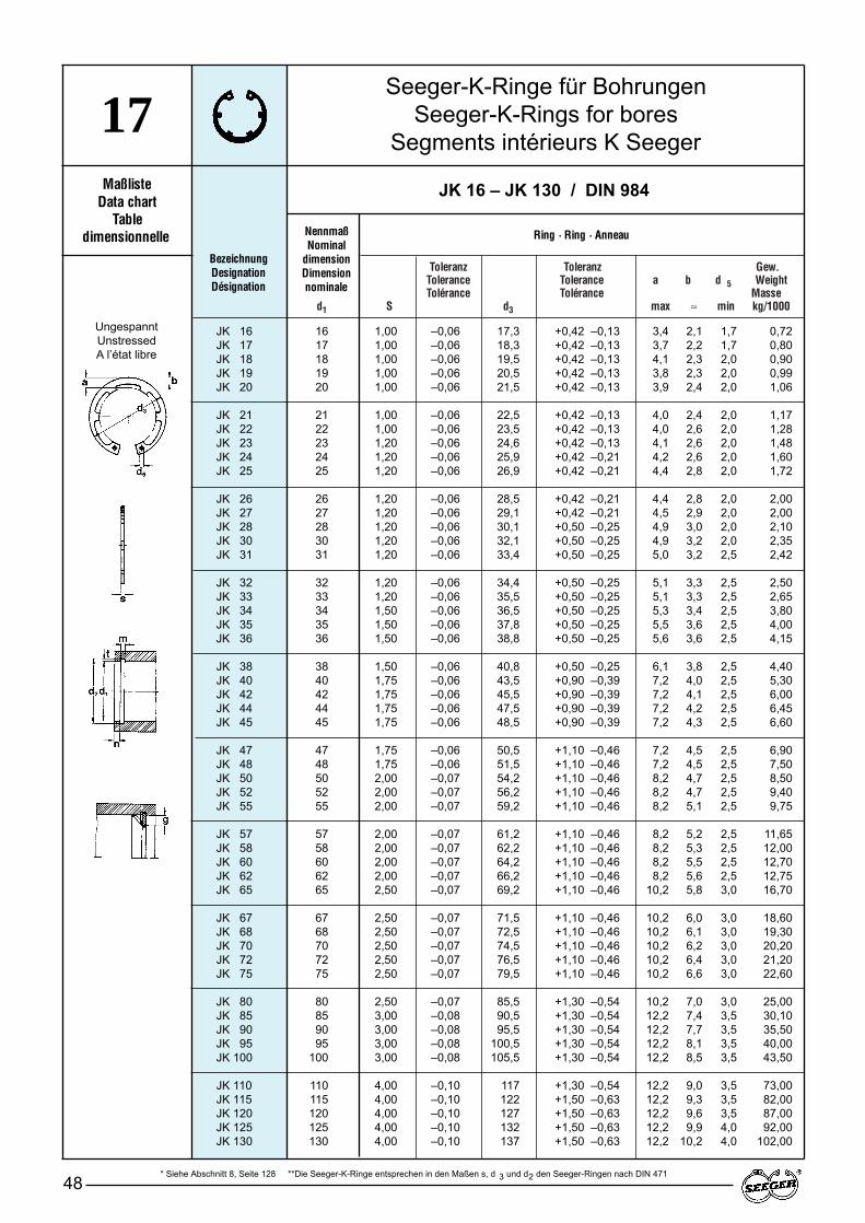
Toleranz Toleranz Gew.Tolerance Tolerance a b d 5 WeightTolérance Tolérance Masse
d1 S d3 max ≈ min kg/1000
Seeger-K-Ringe für BohrungenSeeger-K-Rings for bores
Segments intérieurs K Seeger
48
17Maßliste
Data chartTable
dimensionnelle NennmaßNominal
dimensionDimension nominale
BezeichnungDesignationDésignation
JK 16 – JK 130 / DIN 984
Ring · Ring · Anneau
UngespanntUnstressedA l’état libre
JK 16 16 1,00 –0,06 17,3 +0,42 –0,13 3,4 2,1 1,7 0,72JK 17 17 1,00 –0,06 18,3 +0,42 –0,13 3,7 2,2 1,7 0,80JK 18 18 1,00 –0,06 19,5 +0,42 –0,13 4,1 2,3 2,0 0,90JK 19 19 1,00 –0,06 20,5 +0,42 –0,13 3,8 2,3 2,0 0,99JK 20 20 1,00 –0,06 21,5 +0,42 –0,13 3,9 2,4 2,0 1,06
JK 21 21 1,00 –0,06 22,5 +0,42 –0,13 4,0 2,4 2,0 1,17JK 22 22 1,00 –0,06 23,5 +0,42 –0,13 4,0 2,6 2,0 1,28JK 23 23 1,20 –0,06 24,6 +0,42 –0,13 4,1 2,6 2,0 1,48JK 24 24 1,20 –0,06 25,9 +0,42 –0,21 4,2 2,6 2,0 1,60JK 25 25 1,20 –0,06 26,9 +0,42 –0,21 4,4 2,8 2,0 1,72
JK 26 26 1,20 –0,06 28,5 +0,42 –0,21 4,4 2,8 2,0 2,00JK 27 27 1,20 –0,06 29,1 +0,42 –0,21 4,5 2,9 2,0 2,00JK 28 28 1,20 –0,06 30,1 +0,50 –0,25 4,9 3,0 2,0 2,10JK 30 30 1,20 –0,06 32,1 +0,50 –0,25 4,9 3,2 2,0 2,35JK 31 31 1,20 –0,06 33,4 +0,50 –0,25 5,0 3,2 2,5 2,42
JK 32 32 1,20 –0,06 34,4 +0,50 –0,25 5,1 3,3 2,5 2,50JK 33 33 1,20 –0,06 35,5 +0,50 –0,25 5,1 3,3 2,5 2,65JK 34 34 1,50 –0,06 36,5 +0,50 –0,25 5,3 3,4 2,5 3,80JK 35 35 1,50 –0,06 37,8 +0,50 –0,25 5,5 3,6 2,5 4,00JK 36 36 1,50 –0,06 38,8 +0,50 –0,25 5,6 3,6 2,5 4,15
JK 38 38 1,50 –0,06 40,8 +0,50 –0,25 6,1 3,8 2,5 4,40JK 40 40 1,75 –0,06 43,5 +0,90 –0,39 7,2 4,0 2,5 5,30JK 42 42 1,75 –0,06 45,5 +0,90 –0,39 7,2 4,1 2,5 6,00JK 44 44 1,75 –0,06 47,5 +0,90 –0,39 7,2 4,2 2,5 6,45JK 45 45 1,75 –0,06 48,5 +0,90 –0,39 7,2 4,3 2,5 6,60
JK 47 47 1,75 –0,06 50,5 +1,10 –0,46 7,2 4,5 2,5 6,90JK 48 48 1,75 –0,06 51,5 +1,10 –0,46 7,2 4,5 2,5 7,50JK 50 50 2,00 –0,07 54,2 +1,10 –0,46 8,2 4,7 2,5 8,50JK 52 52 2,00 –0,07 56,2 +1,10 –0,46 8,2 4,7 2,5 9,40JK 55 55 2,00 –0,07 59,2 +1,10 –0,46 8,2 5,1 2,5 9,75
JK 57 57 2,00 –0,07 61,2 +1,10 –0,46 8,2 5,2 2,5 11,65JK 58 58 2,00 –0,07 62,2 +1,10 –0,46 8,2 5,3 2,5 12,00JK 60 60 2,00 –0,07 64,2 +1,10 –0,46 8,2 5,5 2,5 12,70JK 62 62 2,00 –0,07 66,2 +1,10 –0,46 8,2 5,6 2,5 12,75JK 65 65 2,50 –0,07 69,2 +1,10 –0,46 10,2 5,8 3,0 16,70
JK 67 67 2,50 –0,07 71,5 +1,10 –0,46 10,2 6,0 3,0 18,60JK 68 68 2,50 –0,07 72,5 +1,10 –0,46 10,2 6,1 3,0 19,30JK 70 70 2,50 –0,07 74,5 +1,10 –0,46 10,2 6,2 3,0 20,20JK 72 72 2,50 –0,07 76,5 +1,10 –0,46 10,2 6,4 3,0 21,20JK 75 75 2,50 –0,07 79,5 +1,10 –0,46 10,2 6,6 3,0 22,60
JK 80 80 2,50 –0,07 85,5 +1,30 –0,54 10,2 7,0 3,0 25,00JK 85 85 3,00 –0,08 90,5 +1,30 –0,54 12,2 7,4 3,5 30,10JK 90 90 3,00 –0,08 95,5 +1,30 –0,54 12,2 7,7 3,5 35,50JK 95 95 3,00 –0,08 100,5 +1,30 –0,54 12,2 8,1 3,5 40,00JK 100 100 3,00 –0,08 105,5 +1,30 –0,54 12,2 8,5 3,5 43,50
JK 110 110 4,00 –0,10 117 +1,30 –0,54 12,2 9,0 3,5 73,00JK 115 115 4,00 –0,10 122 +1,50 –0,63 12,2 9,3 3,5 82,00JK 120 120 4,00 –0,10 127 +1,50 –0,63 12,2 9,6 3,5 87,00JK 125 125 4,00 –0,10 132 +1,50 –0,63 12,2 9,9 4,0 92,00JK 130 130 4,00 –0,10 137 +1,50 –0,63 12,2 10,2 4,0 102,00
* Siehe Abschnitt 8, Seite 128 **Die Seeger-K-Ringe entsprechen in den Maßen s, d 3 und d2 den Seeger-Ringen nach DIN 471
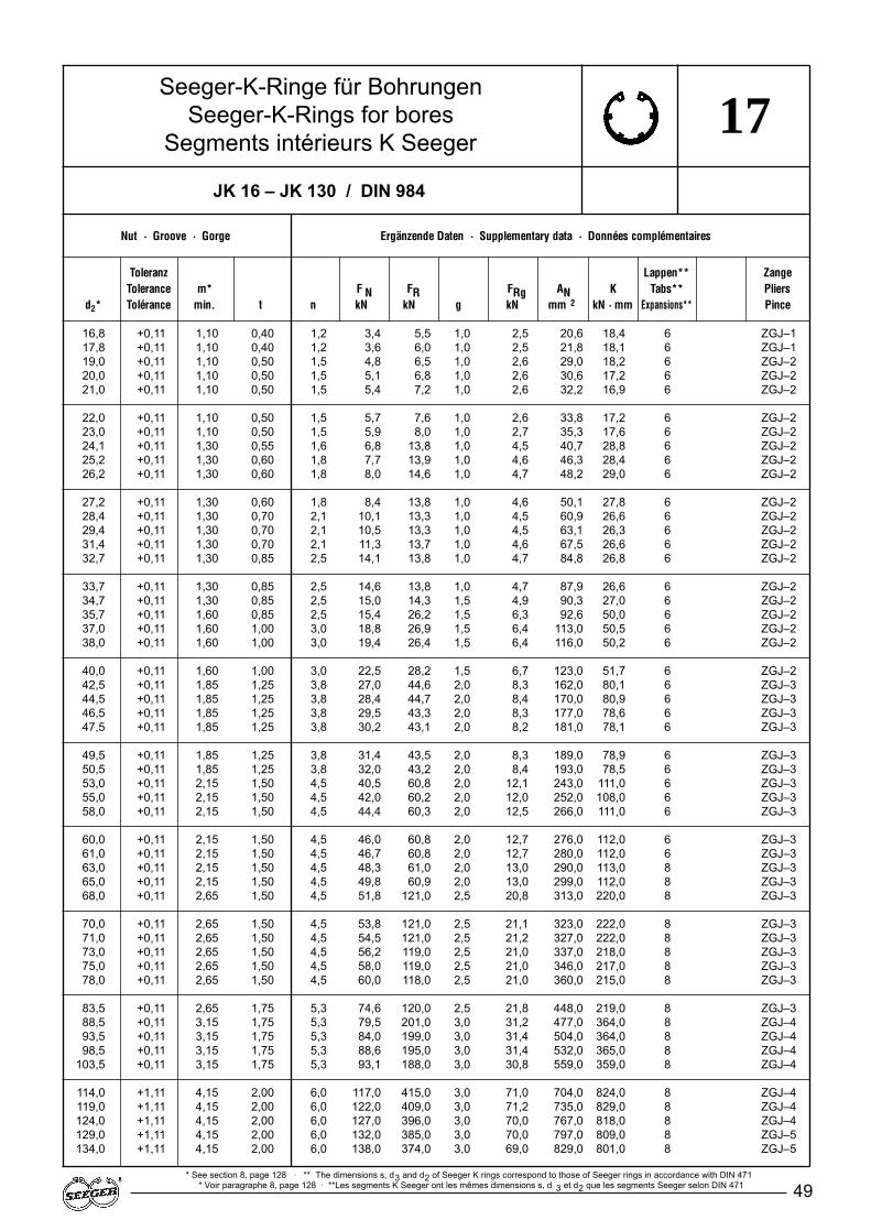
49
17
Nut · Groove · Gorge Ergänzende Daten · Supplementary data · Données complémentaires
Toleranz Lappen** nabl. ZangeTolerance m* F N FR FRg AN K Tabs** x1000 Pliers
d2* Tolérance min. t n kN kN g kN mm 2 kN · mm Expansions** (1/min) Pince
JK 16 – JK 130 / DIN 984
Seeger-K-Ringe für BohrungenSeeger-K-Rings for bores
Segments intérieurs K Seeger
16,8 +0,11 1,10 0,40 1,2 3,4 5,5 1,0 2,5 20,617,8 +0,11 1,10 0,40 1,2 3,6 6,0 1,0 2,5 21,819,0 +0,11 1,10 0,50 1,5 4,8 6,5 1,0 2,6 29,020,0 +0,11 1,10 0,50 1,5 5,1 6,8 1,0 2,6 30,621,0 +0,11 1,10 0,50 1,5 5,4 7,2 1,0 2,6 32,2
22,0 +0,11 1,10 0,50 1,5 5,7 7,6 1,0 2,6 33,823,0 +0,11 1,10 0,50 1,5 5,9 8,0 1,0 2,7 35,324,1 +0,11 1,30 0,55 1,6 6,8 13,8 1,0 4,5 40,725,2 +0,11 1,30 0,60 1,8 7,7 13,9 1,0 4,6 46,326,2 +0,11 1,30 0,60 1,8 8,0 14,6 1,0 4,7 48,2
27,2 +0,11 1,30 0,60 1,8 8,4 13,8 1,0 4,6 50,128,4 +0,11 1,30 0,70 2,1 10,1 13,3 1,0 4,5 60,929,4 +0,11 1,30 0,70 2,1 10,5 13,3 1,0 4,5 63,131,4 +0,11 1,30 0,70 2,1 11,3 13,7 1,0 4,6 67,532,7 +0,11 1,30 0,85 2,5 14,1 13,8 1,0 4,7 84,8
33,7 +0,11 1,30 0,85 2,5 14,6 13,8 1,0 4,7 87,934,7 +0,11 1,30 0,85 2,5 15,0 14,3 1,5 4,9 90,335,7 +0,11 1,60 0,85 2,5 15,4 26,2 1,5 6,3 92,637,0 +0,11 1,60 1,00 3,0 18,8 26,9 1,5 6,4 113,038,0 +0,11 1,60 1,00 3,0 19,4 26,4 1,5 6,4 116,0
40,0 +0,11 1,60 1,00 3,0 22,5 28,2 1,5 6,7 123,042,5 +0,11 1,85 1,25 3,8 27,0 44,6 2,0 8,3 162,044,5 +0,11 1,85 1,25 3,8 28,4 44,7 2,0 8,4 170,046,5 +0,11 1,85 1,25 3,8 29,5 43,3 2,0 8,3 177,047,5 +0,11 1,85 1,25 3,8 30,2 43,1 2,0 8,2 181,0
49,5 +0,11 1,85 1,25 3,8 31,4 43,5 2,0 8,3 189,050,5 +0,11 1,85 1,25 3,8 32,0 43,2 2,0 8,4 193,053,0 +0,11 2,15 1,50 4,5 40,5 60,8 2,0 12,1 243,055,0 +0,11 2,15 1,50 4,5 42,0 60,2 2,0 12,0 252,058,0 +0,11 2,15 1,50 4,5 44,4 60,3 2,0 12,5 266,0
60,0 +0,11 2,15 1,50 4,5 46,0 60,8 2,0 12,7 276,061,0 +0,11 2,15 1,50 4,5 46,7 60,8 2,0 12,7 280,063,0 +0,11 2,15 1,50 4,5 48,3 61,0 2,0 13,0 290,065,0 +0,11 2,15 1,50 4,5 49,8 60,9 2,0 13,0 299,068,0 +0,11 2,65 1,50 4,5 51,8 121,0 2,5 20,8 313,0
70,0 +0,11 2,65 1,50 4,5 53,8 121,0 2,5 21,1 323,071,0 +0,11 2,65 1,50 4,5 54,5 121,0 2,5 21,2 327,073,0 +0,11 2,65 1,50 4,5 56,2 119,0 2,5 21,0 337,075,0 +0,11 2,65 1,50 4,5 58,0 119,0 2,5 21,0 346,078,0 +0,11 2,65 1,50 4,5 60,0 118,0 2,5 21,0 360,0
83,5 +0,11 2,65 1,75 5,3 74,6 120,0 2,5 21,8 448,088,5 +0,11 3,15 1,75 5,3 79,5 201,0 3,0 31,2 477,093,5 +0,11 3,15 1,75 5,3 84,0 199,0 3,0 31,4 504,098,5 +0,11 3,15 1,75 5,3 88,6 195,0 3,0 31,4 532,0
103,5 +0,11 3,15 1,75 5,3 93,1 188,0 3,0 30,8 559,0
114,0 +1,11 4,15 2,00 6,0 117,0 415,0 3,0 71,0 704,0119,0 +1,11 4,15 2,00 6,0 122,0 409,0 3,0 71,2 735,0124,0 +1,11 4,15 2,00 6,0 127,0 396,0 3,0 70,0 767,0129,0 +1,11 4,15 2,00 6,0 132,0 385,0 3,0 70,0 797,0134,0 +1,11 4,15 2,00 6,0 138,0 374,0 3,0 69,0 829,0
18,4 6 ZGJ–118,1 6 ZGJ–118,2 6 ZGJ–217,2 6 ZGJ–216,9 6 ZGJ–2
17,2 6 ZGJ–217,6 6 ZGJ–228,8 6 ZGJ–228,4 6 ZGJ–229,0 6 ZGJ–2
27,8 6 ZGJ–226,6 6 ZGJ–226,3 6 ZGJ–226,6 6 ZGJ–226,8 6 ZGJ–2
26,6 6 ZGJ–227,0 6 ZGJ–250,0 6 ZGJ–250,5 6 ZGJ–250,2 6 ZGJ–2
51,7 6 ZGJ–280,1 6 ZGJ–380,9 6 ZGJ–378,6 6 ZGJ–378,1 6 ZGJ–3
78,9 6 ZGJ–378,5 6 ZGJ–3
111,0 6 ZGJ–3108,0 6 ZGJ–3111,0 6 ZGJ–3
112,0 6 ZGJ–3112,0 6 ZGJ–3113,0 8 ZGJ–3112,0 8 ZGJ–3220,0 8 ZGJ–3
222,0 8 ZGJ–3222,0 8 ZGJ–3218,0 8 ZGJ–3217,0 8 ZGJ–3215,0 8 ZGJ–3
219,0 8 ZGJ–3364,0 8 ZGJ–4364,0 8 ZGJ–4365,0 8 ZGJ–4359,0 8 ZGJ–4
824,0 8 ZGJ–4829,0 8 ZGJ–4818,0 8 ZGJ–4809,0 8 ZGJ–5801,0 8 ZGJ–5
* See section 8, page 128 · ** The dimensions s, d3 and d2 of Seeger K rings correspond to those of Seeger rings in accordance with DIN 471* Voir paragraphe 8, page 128 · **Les segments K Seeger ont les mêmes dimensions s, d 3 et d2 que les segments Seeger selon DIN 471
Toleranz Toleranz Gew.Tolerance Tolerance a b d 5 WeightTolérance Tolérance Masse
d1 S d3 max ≈ min kg/1000
UngespanntUnstressedA l’état libre
Seeger-K-Ringe für BohrungenSeeger-K-Rings for bores
Segments intérieurs K Seeger
50
17Maßliste
Data chartTable
dimensionnelle NennmaßNominal
dimensionDimension nominale
BezeichnungDesignationDésignation
JK 140 – JK 170 / DIN 984
Ring · Ring · Anneau
JK 140 140 4,00 –0,10 148 +1,50 –0,63 14,2 10,7 4,0 112,00JK 150 150 4,00 –0,10 158 +1,50 –0,63 14,2 11,1 4,0 123,00JK 160 160 4,00 –0,10 169 +1,50 –0,63 14,2 11,8 4,5 133,00JK 170 170 4,00 –0,10 179 +1,50 –0,63 14,2 12,3 4,5 145,00
* Siehe Abschnitt 8, Seite 128 · **Die Seeger-K-Ringe entsprechen in den Maßen s, d 3 und d2 den Seeger-Ringen nach DIN 471

Seeger-K-Ringe für BohrungenSeeger-K-Rings for bores
Segments intérieurs K Seeger
51
17
Nut · Groove · Gorge Ergänzende Daten · Supplementary data · Données complémentaires
Toleranz Lappen** nabl. ZangeTolerance m* F N FR FRg AN K Tabs** x1000 Pliers
d2* Tolérance min. t n kN kN g kN mm 2 kN · mm Expansions** (1/min) Pince
JK 140 – JK 170 / DIN 984
144,0 +1,11 4,15 2,00 6,0 148,0 350,0 3,0 66,5 892,0155,0 +1,11 4,15 2,50 7,5 191,0 326,0 3,0 64,0 1198,0165,0 +1,11 4,15 2,50 7,5 212,0 321,0 3,5 54,5 1275,0175,0 +1,11 4,15 2,50 7,5 225,0 349,0 3,5 59,0 1355,0
775,0 8 ZGJ–5748,0 8 ZGJ–5737,0 8 ZGJ–5800,0 8 ZGJ–5
* See section 8, page 128 · ** The dimensions s, d3 and d2 of Seeger K rings correspond to those of Seeger rings in accordance with DIN 471* Voir paragraphe 8, page 128 · **Les segments K Seeger ont les mêmes dimensions s, d 3 et d2 que les segments Seeger selon DIN 471

NennmaßNominal
dimensionDimention nominale
Toleranz Toleranz Gew.Tolerance Tolerance a b d 5 WeightTolérance Tolérance Masse
d1 S d3 max ≈ min kg/1000
AS 12 – AS 100 / DIN 471
Seeger-Ringe für Wellen, schwere AusführungSeeger-Rings for shafts (heavy duty)
Segments extérieurs renforcés Seeger
52
MaßlisteData chart
Tabledimensionnelle
BezeichnungDesignationDésignation
Ring · Ring · Anneau
AS 12 12 1,50 –0,06 11,0 +0,10 –0,36 3,4 1,8 1,7 0,75AS 15 15 1,50 –0,06 13,8 +0,10 –0,36 4,8 2,4 2,0 1,20AS 16 16 1,50 –0,06 14,7 +0,10 –0,36 5,0 2,5 2,0 1,20AS 17 17 1,50 –0,06 15,7 +0,10 –0,36 5,0 2,6 2,0 1,24AS 18 18 1,50 –0,06 16,5 +0,10 –0,36 5,1 2,7 2,0 1,54
AS 19 19 1,50 –0,06 17,5 +0,10 –0,36 5,1 2,7 2,0 1,45AS 20 20 1,75 –0,06 18,5 +0,13 –0,42 5,5 3,0 2,0 2,25AS 22 22 1,75 –0,06 20,5 +0,13 –0,42 6,0 3,1 2,0 2,30AS 24 24 1,75 –0,06 22,2 +0,21 –0,42 6,3 3,2 2,0 2,70AS 25 25 2,00 –0,07 23,2 +0,21 –0,42 6,4 3,4 2,0 3,35
AS 26 26 2,00 –0,07 23,6 +0,21 –0,42 6,6 3,3 2,0 3,65AS 27 27 2,00 –0,07 24,7 +0,21 –0,42 6,6 3,4 2,0 3,85AS 28 28 2,00 –0,07 25,9 +0,21 –0,42 6,5 3,5 2,0 3,90AS 29 29 2,00 –0,07 26,9 +0,21 –0,42 6,5 3,8 2,0 4,30AS 30 30 2,00 –0,07 27,9 +0,21 –0,42 6,5 4,1 2,0 5,00
AS 32 32 2,00 –0,07 29,6 +0,21 –0,42 6,5 4,1 2,5 5,40AS 34 34 2,50 –0,07 31,5 +0,25 –0,50 6,6 4,2 2,5 6,80AS 35 35 2,50 –0,07 32,2 +0,25 –0,50 6,7 4,2 2,5 7,10AS 36 36 2,50 –0,07 33,2 +0,25 –0,50 6,7 4,2 2,5 7,50AS 38 38 2,50 –0,07 35,2 +0,25 –0,50 6,8 4,3 2,5 8,00
AS 40 40 2,50 –0,07 36,5 +0,39 –0,90 7,0 4,4 2,5 8,20AS 42 42 2,50 –0,07 38,5 +0,39 –0,90 7,2 4,5 2,5 9,60AS 44 44 2,50 –0,07 40,5 +0,39 –0,90 7,2 4,5 2,5 10,40AS 45 45 2,50 –0,07 41,5 +0,39 –0,90 7,5 4,7 2,5 10,80AS 48 48 2,50 –0,07 44,5 +0,39 –0,90 7,8 5,0 2,5 12,20
AS 50 50 3,00 –0,08 45,8 +0,39 –0,90 8,0 5,1 2,5 14,80AS 52 52 3,00 –0,08 47,8 +0,39 –0,90 8,2 5,2 2,5 15,40AS 55 55 3,00 –0,08 50,8 +0,46 –1,10 8,5 5,4 2,5 17,00AS 58 58 3,00 –0,08 53,8 +0,46 –1,10 8,8 5,6 2,5 19,40AS 60 60 3,00 –0,08 55,8 +0,46 –1,10 9,0 5,8 2,5 20,00
AS 65 65 4,00 –0,10 60,8 +0,46 –1,10 9,3 6,3 3,0 31,00AS 70 70 4,00 –0,10 65,5 +0,46 –1,10 9,5 6,6 3,0 32,20AS 75 75 4,00 –0,10 70,5 +0,46 –1,10 9,7 7,0 3,0 39,80AS 80 80 4,00 –0,10 74,5 +0,46 –1,10 9,8 7,4 3,0 42,40AS 85 85 4,00 –0,10 79,5 +0,46 –1,10 10,0 7,8 3,5 47,00
AS 90 90 4,00 –0,10 84,5 +0,54 –1,30 10,2 8,2 3,5 55,60AS 95 95 4,00 –0,10 89,5 +0,54 –1,30 10,2 8,6 3,5 61,20AS 100 100 4,00 –0,10 94,5 +0,54 –1,30 10,5 9,0 3,5 72,00
18
nach Wahl des Herstellers
manufacturer’s choice
suivant les disponibilitésdu fabricant
UngespanntUnstressedA l’état libre
53
Nut · Groove · Gorge Ergänzende Daten · Supplementary data · Données complémentaires
Toleranz nabl. ZangeTolerance m* F N FR FRg AN x1000 Pliers
d2* Tolérance min. t n kN kN g kN mm 2 B (1/min) Pince
* Siehe Abschnitt 8, Seite 128 · * See section 8, page 128 · * V oir paragraphe 8, page 128
AS 12 – AS 100 / DIN 471
18
11,5 –0,11 1,60 0,25 0,7 1,53 11,30 1,0 4,5 9,214,3 –0,11 1,60 0,35 0,7 3,20 15,50 1,0 4,5 18,315,2 –0,11 1,60 0,40 1,2 3,26 16,70 1,0 4,5 19,616,2 –0,11 1,60 0,40 1,5 4,32 18,00 1,0 4,5 25,917,0 –0,11 1,60 0,50 1,8 5,50 26,60 1,5 5,8 33,0
18,0 –0,11 1,60 0,50 1,8 5,78 26,60 1,5 5,9 34,719,0 –0,13 1,85 0,50 1,6 5,60 36,30 1,5 8,2 33,821,0 –0,21 1,85 0,50 1,5 5,60 36,00 1,5 8,1 33,822,9 –0,21 1,85 0,55 1,9 7,95 34,20 1,5 7,6 47,723,9 –0,21 2,15 0,55 1,9 8,30 45,00 1,5 10,3 49,7
24,4 –0,21 2,15 0,80 2,4 10,70 44,00 1,5 10,0 63,025,5 –0,21 2,15 0,75 2,3 10,30 45,50 1,5 10,6 62,026,6 –0,21 2,15 0,70 2,1 10,00 57,00 1,5 13,4 60,027,6 –0,21 2,15 0,70 2,1 10,40 56,50 1,5 13,3 62,228,6 –0,21 2,15 0,70 2,1 10,70 57,00 1,5 13,6 64,4
30,3 –0,21 2,15 0,85 2,5 12,90 57,00 1,5 13,6 77,832,3 –0,25 2,65 0,85 2,8 16,40 87,00 1,5 15,6 99,033,0 –0,25 2,65 1,00 3,0 17,80 86,00 1,5 15,4 107,034,0 –0,25 2,65 1,00 3,3 20,10 101,50 2,0 18,3 121,036,0 –0,25 2,65 1,00 3,3 21,20 101,00 2,0 18,6 127,0
37,5 –0,25 2,65 1,25 3,8 25,30 104,00 2,0 19,3 152,039,5 –0,25 2,65 1,25 3,8 26,70 102,00 2,0 19,2 160,041,5 –0,25 2,65 1,25 3,8 27,90 101,00 2,0 19,1 168,042,5 –0,25 2,65 1,25 3,8 28,60 100,00 2,0 19,1 172,045,5 –0,25 2,65 1,25 3,8 30,70 101,00 2,0 19,5 184,0
47,0 –0,25 3,15 1,50 4,5 38,20 165,00 2,0 32,4 229,049,0 –0,25 3,15 1,50 4,5 39,70 165,00 2,5 26,0 238,052,0 –0,30 3,15 1,50 4,5 42,00 161,00 2,5 25,6 252,055,0 –0,30 3,15 1,50 4,5 44,30 160,00 2,5 26,0 266,057,0 –0,30 3,15 1,50 4,5 46,00 156,00 2,5 25,4 276,0
62,0 –0,30 4,15 1,50 4,5 49,80 346,00 2,5 58,0 299,067,0 –0,30 4,15 1,50 4,5 53,80 343,00 2,5 59,0 323,072,0 –0,30 4,15 1,50 4,5 57,60 333,00 2,5 58,0 346,076,5 –0,30 4,15 1,75 5,3 71,60 328,00 3,0 50,0 430,081,5 –0,35 4,15 1,75 5,3 76,30 383,00 3,0 59,4 458,0
86,5 –0,35 4,15 1,75 5,3 80,80 386,00 3,0 61,0 485,091,5 –0,35 4,15 1,75 5,3 85,50 378,00 3,5 52,0 513,096,5 –0,35 4,15 1,75 5,3 90,00 368,00 3,5 51,6 540,0
2,25 75,0 ZGA–12,25 57,0 ZGA–12,25 44,0 ZGA–12,25 46,0 ZGA–11,56 42,7 ZGA–2
1,56 36,0 ZGA–22,12 36,0 ZGA–22,12 29,0 ZGA–22,12 29,2 ZGA–22,78 25,0 ZGA–2
2,73 27,0 ZGA–22,78 25,0 ZGA–21,78 22,2 ZGA–21,78 22,0 ZGA–21,78 21,1 ZGA–2
1,78 18,4 ZGA–22,78 17,8 ZGA–32,78 16,5 ZGA–32,04 16,0 ZGA–32,04 14,5 ZGA–3
2,04 14,3 ZGA–32,04 13,0 ZGA–32,04 12,0 ZGA–32,04 11,4 ZGA–32,04 10,3 ZGA–3
2,25 10,5 ZGA–32,25 9,8 ZGA–32,25 9,0 ZGA–32,25 8,2 ZGA–32,25 7,6 ZGA–3
2,56 6,6 ZGA–32,56 6,5 ZGA–32,56 5,7 ZGA–32,56 6,1 ZGA–31,78 5,7 ZGA–4
1,78 5,0 ZGA–41,78 5,0 ZGA–41,78 4,0 ZGA–4
Seeger-Ringe für Wellen, schwere AusführungSeeger-Rings for shafts (heavy duty)
Segments extérieurs renforcés Seeger
NennmaßNominal
dimensionDimention nominale
Toleranz Toleranz Gew.Tolerance Tolerance a b d 5 WeightTolérance Tolérance Masse
d1 S d3 max ≈ min kg/1000
Seeger-Ringe für Bohrungen, schwere AusführungSeeger-Rings for bores (heavy duty)
Segments intérieurs renforcés Seeger
54
MaßlisteData chart
Tabledimensionnelle
BezeichnungDesignationDésignation
Ring · Ring · Anneau
JS 20 20 1,50 –0,06 21,5 +0,42 –0,21 4,5 2,4 2,0 1,4JS 22 22 1,50 –0,06 23,5 +0,42 –0,21 4,7 2,8 2,0 1,9JS 24 24 1,50 –0,06 25,9 +0,42 –0,21 4,9 3,0 2,0 2,0JS 25 25 1,50 –0,06 26,9 +0,42 –0,21 5,0 3,1 2,0 2,1JS 26 26 1,50 –0,06 27,9 +0,42 –0,21 5,1 3,1 2,0 2,3
JS 27 27 1,50 –0,06 29,1 +0,50 –0,25 5,1 3,2 2,0 2,4JS 28 28 1,50 –0,06 30,1 +0,50 –0,25 5,3 3,2 2,0 2,5JS 30 30 1,50 –0,06 32,1 +0,50 –0,25 5,5 3,3 2,0 2,7JS 32 32 1,50 –0,06 34,4 +0,50 –0,25 5,7 3,4 2,0 2,9JS 34 34 1,75 –0,06 36,5 +0,50 –0,25 5,9 3,7 2,5 4,1
JS 35 35 1,75 –0,06 37,8 +0,50 –0,25 6,0 3,8 2,5 4,5JS 37 37 1,75 –0,06 39,8 +0,50 –0,25 6,2 3,9 2,5 4,7JS 38 38 1,75 –0,06 40,8 +0,50 –0,25 6,3 3,9 2,5 4,8JS 40 40 2,00 –0,07 43,5 +0,90 –0,39 6,5 3,9 2,5 5,1JS 42 42 2,00 –0,07 45,5 +0,90 –0,39 6,7 4,1 2,5 5,6
JS 45 45 2,00 –0,07 48,5 +0,90 –0,39 7,0 4,3 2,5 6,3JS 47 47 2,00 –0,07 50,5 +1,10 –0,46 7,2 4,4 2,5 6,7JS 50 50 2,50 –0,07 54,2 +1,10 –0,46 7,5 4,6 2,5 8,8JS 52 52 2,50 –0,07 56,2 +1,10 –0,46 7,7 4,7 2,5 9,9JS 55 55 2,50 –0,07 59,2 +1,10 –0,46 8,0 5,0 2,5 10,4
JS 60 60 3,00 –0,08 64,2 +1,10 –0,46 8,5 5,4 2,5 15,9JS 62 62 3,00 –0,08 66,2 +1,10 –0,46 8,6 5,5 2,5 16,1JS 64 64 3,00 –0,08 68,2 +1,10 –0,46 8,7 5,6 3,0 16,5JS 65 65 3,00 –0,08 69,2 +1,10 –0,46 8,7 5,8 3,0 16,6JS 68 68 3,00 –0,08 72,5 +1,10 –0,46 8,8 6,1 3,0 17,2
JS 70 70 3,00 –0,08 74,5 +1,10 –0,46 9,0 6,2 3,0 18,0JS 72 72 3,00 –0,08 76,5 +1,10 –0,46 9,2 6,4 3,0 21,7JS 75 75 3,00 –0,08 79,5 +1,10 –0,46 9,3 6,6 3,0 22,6JS 80 80 4,00 –0,10 85,5 +1,30 –0,54 9,5 7,0 3,0 33,2JS 85 85 4,00 –0,10 90,5 +1,30 –0,54 9,7 7,2 3,5 33,8
JS 90 90 4,00 –0,10 95,5 +1,30 –0,54 10,0 7,6 3,5 41,3JS 95 95 4,00 –0,10 100,5 +1,30 –0,54 10,3 8,1 3,5 46,7JS 100 100 4,00 –0,10 105,5 +1,30 –0,54 10,5 8,4 3,5 50,7
19JS 20 – JS 100 / DIN 472
nach Wahl des Herstellers
manufacturer’s choice
suivant les disponibilitésdu fabricant
UngespanntUnstressedA l’état libre
Seeger-Ringe für Bohrungen, schwere AusführungSeeger-Rings for bores (heavy duty)
Segments intérieurs renforcés Seeger
55
Nut · Groove · Gorge Ergänzende Daten · Supplementary data · Données complémentaires
Toleranz ZangeTolerance m* F N FR FRg AN nabl. Pliers
d2* Tolérance min. t n kN kN g kN mm 2 B x1000 Pince
* Siehe Abschnitt 8, Seite 128 · * See section 8, page 128 · * V oir paragraphe 8, page 128
JS 20 – JS 100 / DIN 472
19
21,0 +0,15 1,60 0,50 1,5 5,4 16,2 1,0 5,8 3223,0 +0,15 1,60 0,50 1,5 5,9 18,0 1,0 6,1 3525,2 +0,21 1,60 0,60 1,8 7,7 21,7 1,0 7,2 4626,2 +0,21 1,60 0,60 1,8 8,0 22,8 1,0 7,3 4827,2 +0,21 1,60 0,60 1,8 8,4 21,6 1,0 7,2 50
28,4 +0,21 1,60 0,70 2,1 10,1 20,8 1,0 7,0 6029,4 +0,21 1,60 0,70 2,1 10,5 20,8 1,0 7,0 6331,4 +0,25 1,60 0,70 2,1 11,3 21,4 1,0 7,2 6733,7 +0,25 1,60 0,85 2,6 14,6 21,4 1,0 7,3 8735,7 +0,25 1,85 0,85 2,6 15,4 35,6 1,5 8,6 92
37,0 +0,25 1,85 1,00 3,0 18,8 36,6 1,5 8,7 11339,0 +0,25 1,85 1,00 3,0 19,8 36,8 1,5 8,8 11940,0 +0,25 1,85 1,00 3,0 22,5 38,3 1,5 9,1 12342,5 +0,25 2,15 1,25 3,8 27,0 58,4 2,0 10,9 16244,5 +0,25 2,15 1,25 3,8 28,4 58,5 2,0 11,0 170
47,5 +0,25 2,15 1,25 3,8 30,2 56,5 2,0 10,7 18149,5 +0,25 2,15 1,25 3,8 31,4 57,0 2,0 10,8 18953,0 +0,30 2,65 1,50 4,5 40,5 95,5 2,0 19,0 24355,0 +0,30 2,65 1,50 4,5 42,0 94,6 2,0 18,8 25258,0 +0,30 2,65 1,50 4,5 44,4 94,7 2,0 19,6 266
63,0 +0,30 3,15 1,50 4,5 48,3 137,0 2,0 29,2 29065,0 +0,30 3,15 1,50 4,5 49,8 137,0 2,0 29,2 29967,0 +0,30 3,15 1,50 4,5 51,4 137,0 2,0 30,0 30868,0 +0,30 3,15 1,50 4,5 51,8 174,0 2,5 30,0 31371,0 +0,30 3,15 1,50 4,5 54,5 174,0 2,5 30,6 327
73,0 +0,30 3,15 1,50 4,5 56,2 171,0 2,5 30,3 33775,0 +0,30 3,15 1,50 4,5 58,0 172,0 2,5 30,3 34678,0 +0,30 3,15 1,50 4,5 60,0 170,0 2,5 30,3 36083,5 +0,35 4,15 1,75 5,3 74,6 308,0 2,5 56,0 44888,5 +0,35 4,15 1,75 5,3 79,5 358,0 3,0 55,0 477
93,5 +0,35 4,15 1,75 5,3 84,0 354,0 3,0 56,0 50498,5 +0,35 4,15 1,75 5,3 88,6 347,0 3,0 56,0 532
103,5 +0,35 4,15 1,75 5,3 93,1 335,0 3,0 55,0 559
2,25 ZGJ–22,25 ZGJ–21,56 ZGJ–21,56 ZGJ–21,56 ZGJ–2
1,56 ZGJ–21,56 ZGJ–21,56 ZGJ–21,56 ZGJ–21,36 ZGJ–3
1,36 ZGJ–31,36 ZGJ–31,36 ZGJ–31,31 ZGJ–31,31 ZGJ–3
1,31 ZGJ–31,31 ZGJ–31,57 ZGJ–31,57 ZGJ–31,57 ZGJ–3
2,25 ZGJ–32,25 ZGJ–32,25 ZGJ–31,44 ZGJ–31,44 ZGJ–3
1,44 ZGJ–31,44 ZGJ–31,44 ZGJ–32,56 ZGJ–31,78 ZGJ–4
1,78 ZGJ–41,78 ZGJ–41,78 ZGJ–4
56
4.
Gruppe 2:Selbstsperrende Seeger-Ringe
Werkstoff: Federstahl
Härte: Siehe Maßlisten
Oberflächenschutz:nach Wahl des Herstellers– phosphatiert und geölt– brüniert und geölt
Sonderausführung auf Anfrage:– blank geölt– verzinkt– Bronze CuSn8siehe Seite 113
Zur Beachtung:Die Werte in den Maßlisten für dieDicke s gelten für Ringe in phospha-tierter, geschwärzter oder blanker Aus-führung. Bei anderen Oberflächenbe-schichtungen vergrößern sich dieseMaße entsprechend den Schichtdicken.
Beschreibung der Ringe:Siehe Seite 7 – 8
Haltekraft H:Die in den Maßlisten angegebenenWerte nennen die maximalen Halte-kräfte (ohne Sicherheit). Sie gelten fürein Wellen- bzw. Gehäusematerial miteiner maximalen Festigkeit von 650N/mm2 und einer Oberfläche, wie siesich durch Drehen ergibt und denRingwerkstoff Federstahl. Bei geschlif-fener, gehärteter oder galvanisch be-handelter Oberfläche (Schmier-wirkung) verringern sich die Halte-kräfte. Dies gilt auch für galvanisch be-handelte selbstsperrende Seeger-
Group 2:Self-locking Seeger-Rings
Material: Spring steel
Hardness: See data charts
Surface protection:To manufacturer's choice– phosphated and oiled– bleckened and oiled
Special versions Please enquire:– self-finish and oiled– zinc plated– bronze CuSn8see Page 113
Please note:The values given in the data charts forthickness s apply to phosphated,blackened or self-finish rings. In theevent of different surface coatingsbeing chosen, these dimensions willbe increased by the correspondingcoating thickness.
Description of the rings:See Pages 7 – 8
Retaining force H:The values given in the data chartsspecify the maximum retaining forces(without safety factor). They apply to ashaft or housing material with a maxi-mum strength of 650 N/mm 2 and a sur-face resulting from turning and usingspring steel stock. Retaining forces arereduced when using ground, hardenedor galvanically treated surfaces (lubri-cation effect). This also applies to gal-vanically treated self-locking Seegerrings. When using rings manufacturedfrom bronze CuSn8, the retaining force
Groupe 2:Segments d'arrêt Seeger autobloquants
Matière: Acier à ressort
Dureté: Voir tables dimensionnelles
Protection de surface:au choix du fabricant– phosphatée et huilée– noircie et huilée
Exécutions spéciales sur demande:– polie et huilée– zinguée– bronze CuSn8voir page 113
Remarque:Les valeurs indiquées dans les tablesdimensionnelles pour l'épaisseur 's'sont valables pour des exécutionsphosphatées, noircies ou polies. Encas de traitement de surface, cette di-mension doit être augmentée del'épaisseur du revêtement.
Description des segments d'arrêt:Voir pages 7 – 8
Force de retenue H: Les valeurs indiquées dans les tablesdimensionnelles donnent les forces deretenue maximum (sans marge de sé-curité). Elles sont valables pour desarbres ou alésages exécutés dans unematière présentant une résistance ma-ximum de 650 N/mm2 et un état desurface correspondant à celui obtenupar usinage au tour ainsi que pour dessegments d'arrêt exécutés en acier àressort. Dans les cas de surfaces rec-tifiées, trempées ou ayant subi un trai-tement de surface galvanique, les for-
MaßlistenData charts
Tables dimensionnelles
Maßliste Seite BezeichnungData Chart Page DesignationTable dim. Page Désignation
21 58 – 59 Seeger-Greifringe / Seeger Grip-Rings / Colliers d'étranglement Seeger G...
23 60 Seeger-Klemmscheiben / Seeger Reinforced Circular Self-locking Rings / KS...Anneaux dentelés Seeger renforcés
24/25 62 – 65 Seeger-Zackenringe / Seeger Circular Self-locking Rings / ZA.../ZJ...Anneaux dentelés Seeger
57
4.Maßlisten
Data chartsTables dimensionnelles
Ringe. Bei Anwendung von Ringenaus Bronze CuSn8 ergibt sich eben-falls eine Verkleinerung der Haltekraftentsprechend dem kleineren E-Moduldieses Werkstoffes.
Montage:Siehe Seite 132 – 133
is also reduced corresponding to thismaterial's lower modulus of elasticity.
Assembly: See Page 132 – 133
ces de retenue diminuent (effet degraissage). Ceci est également valablepour les segments d'arrêt autobloquantsayant subi un traitement de protectiongalvanique. En cas d'utilisation debronze CuSn8, une réduction de la for-ce de retenue interviendra en fonctiondu module d'élasticité plus réduit decette matière.
Montage: Voir page132 – 133
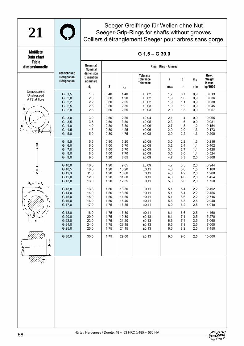
NennmaßNominal
dimensionDimention nominale
Toleranz Toleranz Gew.Tolerance Tolerance a b d 5 WeightTolérance Tolérance Masse
d1 S d3 max ≈ min kg/1000
58
MaßlisteData chart
Tabledimensionnelle
BezeichnungDesignationDésignation
Ring · Ring · Anneau
Seeger-Greifringe für Wellen ohne NutSeeger-Grip-Rings for shafts without grooves
Colliers d’étranglement Seeger pour arbres sans gorge
G 1,5 – G 30,0
G 1,5 1,5 0,40 1,40 ±0,02 1,7 0,7 0,9 0,013G 2,0 2,0 0,60 1,90 ±0,02 1,9 1,0 0,9 0,036G 2,2 2,2 0,60 2,05 ±0,02 1,9 1,1 0,9 0,038G 2,5 2,5 0,60 2,35 ±0,03 1,9 1,2 0,9 0,045G 2,8 2,8 0,60 2,65 ±0,03 2,0 1,3 0,9 0,057
G 3,0 3,0 0,60 2,85 ±0,04 2,1 1,4 0,9 0,065G 3,5 3,5 0,60 3,30 ±0,05 2,3 1,6 0,9 0,081G 4,0 4,0 0,80 3,80 ±0,06 2,7 1,8 1,2 0,154G 4,5 4,5 0,80 4,25 ±0,06 2,9 2,0 1,3 0,173G 5,0 5,0 0,80 4,75 ±0,08 2,9 2,2 1,3 0,200
G 5,5 5,5 0,80 5,20 ±0,08 3,0 2,2 1,3 0,216G 6,0 6,0 1,00 5,70 ±0,08 3,2 2,4 1,4 0,402G 7,0 7,0 1,00 6,70 ±0,09 3,4 2,7 1,4 0,428G 8,0 8,0 1,00 7,70 ±0,09 3,5 3,0 1,4 0,524G 9,0 9,0 1,20 8,65 ±0,09 4,7 3,3 2,0 0,808
G 10,0 10,0 1,20 9,65 ±0,09 4,7 3,5 2,0 0,944G 10,5 10,5 1,20 10,20 ±0,11 4,0 3,8 1,5 1,100G 11,0 11,0 1,20 10,60 ±0,11 4,8 4,2 2,0 1,208G 12,0 12,0 1,20 11,60 ±0,11 4,8 4,6 2,0 1,454G 13,0 13,0 1,20 12,55 ±0,11 5,3 5,0 2,0 1,750
G 13,8 13,8 1,50 13,30 ±0,11 5,1 5,4 2,2 2,492G 14,0 14,0 1,50 13,50 ±0,11 5,1 5,4 2,2 2,456G 15,0 15,0 1,50 14,50 ±0,11 5,1 5,6 2,2 2,716G 16,0 16,0 1,50 15,40 ±0,11 5,6 5,8 2,5 2,940G 17,0 17,0 1,75 16,35 ±0,11 6,0 6,2 2,5 4,010
G 18,0 18,0 1,75 17,30 ±0,11 6,1 6,6 2,5 4,460G 20,0 20,0 1,75 19,30 ±0,13 6,1 7,1 2,5 5,270G 22,0 22,0 1,75 21,20 ±0,13 6,6 7,4 2,5 6,060G 24,0 24,0 1,75 23,15 ±0,13 6,6 7,8 2,5 7,000G 25,0 25,0 1,75 24,15 ±0,13 6,6 8,2 2,5 7,450
G 30,0 30,0 1,75 29,00 ±0,13 9,0 9,0 2,5 10,000
21
UngespanntUnstressedA l’état libre
Härte / Hardeness / Dureté: 48 ÷ 53 HRC ^ 485 ÷ 560 HV=
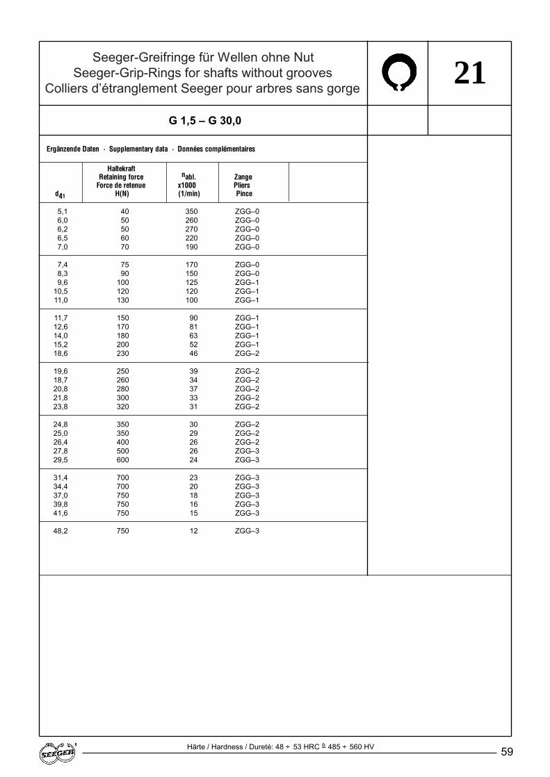
Seeger-Greifringe für Wellen ohne NutSeeger-Grip-Rings for shafts without grooves
Colliers d’étranglement Seeger pour arbres sans gorge
59
21
Ergänzende Daten · Supplementary data · Données complémentaires
HaltekraftRetaining force nabl. Zange
Force de retenue x1000 Pliersd41 H(N) (1/min) Pince
Härte / Hardness / Dureté: 48 ÷ 53 HRC = 485 ÷ 560 HV
G 1,5 – G 30,0
5,1 40 350 ZGG–06,0 50 260 ZGG–06,2 50 270 ZGG–06,5 60 220 ZGG–07,0 70 190 ZGG–0
7,4 75 170 ZGG–0 8,3 90 150 ZGG–09,6 100 125 ZGG–1
10,5 120 120 ZGG–111,0 130 100 ZGG–1
11,7 150 90 ZGG–112,6 170 81 ZGG–114,0 180 63 ZGG–115,2 200 52 ZGG–118,6 230 46 ZGG–2
19,6 250 39 ZGG–218,7 260 34 ZGG–220,8 280 37 ZGG–221,8 300 33 ZGG–223,8 320 31 ZGG–2
24,8 350 30 ZGG–225,0 350 29 ZGG–226,4 400 26 ZGG–227,8 500 26 ZGG–329,5 600 24 ZGG–3
31,4 700 23 ZGG–334,4 700 20 ZGG–337,0 750 18 ZGG–339,8 750 16 ZGG–341,6 750 15 ZGG–3
48,2 750 12 ZGG–3
^

NennmaßNominal
dimensionDimention nominale
Seeger-Klemmscheiben für Wellen und NutSeeger-Reinforced Circular Self-locking Rings for shafts without grooves
Colliers d’étranglement Seeger pour arbres sans gorge
60
MaßlisteData chart
Tabledimensionnelle
Toleranz Zacken Gewicht HaltekraftTolerance teeths Weight x Retaining forceTolérance dents Masse Force de retenue
d1*(h 9) s d3 d4 max kg/1000 ≈ H(N)
BezeichnungDesignationDésignation
KS 1,5 – KS 10
Ring · Ring · Anneau
KS 1,5 1,5 0,25 1,30 6,00 3 0,10 2,5 200KS 2 2,0 0,30 1,80 7,00 3 0,13 2,5 400KS 2,5 2,5 0,30 2,30 8,25 3 0,15 2,5 700KS 3 3,0 0,40 2,80 10,00 3 0,20 3,0 1200KS 3,5 3,5 0,40 3,25 11,50 3 0,25 3,0 1200
KS 4 4,0 0,50 3,75 13,00 4 0,50 3,5 1300KS 5 5,0 0,50 4,75 15,00 5 0,75 3,5 1500KS 6 6,0 0,60 5,75 16,50 6 1,15 4,0 1800KS 7 7,0 0,60 6,75 18,00 6 1,25 4,0 2000KS 8 8,0 0,70 7,75 19,50 6 1,40 4,0 3000
KS 9 9,0 0,70 8,75 21,00 6 1,50 4,5 3500KS 10 10,0 0,80 9,75 22,00 6 1,65 4,5 4000
23
Ergänzende Daten Supplementary data
Données complémentaires
^
* Wenn die Haltekraft nicht voll genutzt wird, kann h 9 durch h 10 ersetzt werden.* If full use is not made of the retaining force, h 9 can be replaced by h 10
* Si la capacité de charge n’est pas utilisée complètement, remplacer h 9 par h 10
Härte / Hardness / Dureté: 48 ÷ 52 HRC = 485 ÷ 545 HV

61
NotizenNotesNotes
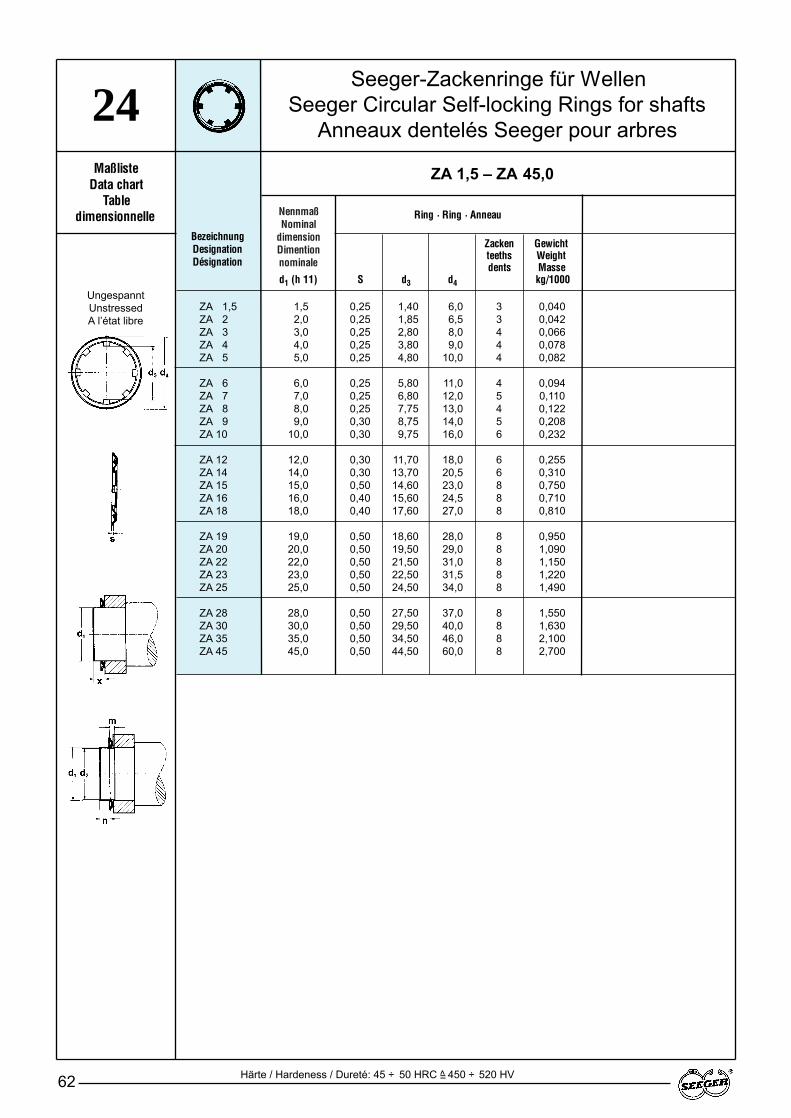
NennmaßNominal
dimensionDimention nominale
Toleranz Zacken GewichtTolerance teeths WeightTolérance dents Masse
d1 (h 11) S d3 d4 max kg/1000
Härte / Hardeness / Dureté: 45 ÷ 50 HRC ^ 450 ÷ 520 HV
Seeger-Zackenringe für WellenSeeger Circular Self-locking Rings for shafts
Anneaux dentelés Seeger pour arbres
62
MaßlisteData chart
Tabledimensionnelle
BezeichnungDesignationDésignation
ZA 1,5 – ZA 45,0
Ring · Ring · Anneau
ZA 1,5 1,5 0,25 1,40 6,0 3 0,040ZA 2 2,0 0,25 1,85 6,5 3 0,042ZA 3 3,0 0,25 2,80 8,0 4 0,066ZA 4 4,0 0,25 3,80 9,0 4 0,078ZA 5 5,0 0,25 4,80 10,0 4 0,082
ZA 6 6,0 0,25 5,80 11,0 4 0,094ZA 7 7,0 0,25 6,80 12,0 5 0,110ZA 8 8,0 0,25 7,75 13,0 4 0,122ZA 9 9,0 0,30 8,75 14,0 5 0,208ZA 10 10,0 0,30 9,75 16,0 6 0,232
ZA 12 12,0 0,30 11,70 18,0 6 0,255ZA 14 14,0 0,30 13,70 20,5 6 0,310ZA 15 15,0 0,50 14,60 23,0 8 0,750ZA 16 16,0 0,40 15,60 24,5 8 0,710ZA 18 18,0 0,40 17,60 27,0 8 0,810
ZA 19 19,0 0,50 18,60 28,0 8 0,950ZA 20 20,0 0,50 19,50 29,0 8 1,090ZA 22 22,0 0,50 21,50 31,0 8 1,150ZA 23 23,0 0,50 22,50 31,5 8 1,220ZA 25 25,0 0,50 24,50 34,0 8 1,490
ZA 28 28,0 0,50 27,50 37,0 8 1,550ZA 30 30,0 0,50 29,50 40,0 8 1,630ZA 35 35,0 0,50 34,50 46,0 8 2,100ZA 45 45,0 0,50 44,50 60,0 8 2,700
24
=
UngespanntUnstressedA l’état libre
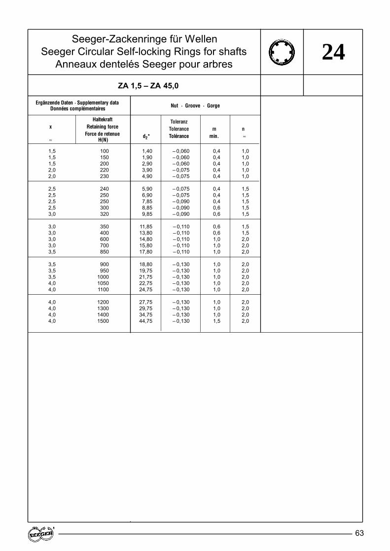
ToleranzTolerance m n FN
d2* Tolérance min. ≈ n kN
Seeger-Zackenringe für WellenSeeger Circular Self-locking Rings for shafts
Anneaux dentelés Seeger pour arbres
63
Nut · Groove · Gorge
ZA 1,5 – ZA 45,0
24
1,5 100 1,40 – 0,060 0,4 1,01,5 150 1,90 – 0,060 0,4 1,01,5 200 2,90 – 0,060 0,4 1,02,0 220 3,90 – 0,075 0,4 1,02,0 230 4,90 – 0,075 0,4 1,0
2,5 240 5,90 – 0,075 0,4 1,52,5 250 6,90 – 0,075 0,4 1,52,5 250 7,85 – 0,090 0,4 1,52,5 300 8,85 – 0,090 0,6 1,53,0 320 9,85 – 0,090 0,6 1,5
3,0 350 11,85 – 0,110 0,6 1,53,0 400 13,80 – 0,110 0,6 1,53,0 600 14,80 – 0,110 1,0 2,03,0 700 15,80 – 0,110 1,0 2,03,5 850 17,80 – 0,110 1,0 2,0
3,5 900 18,80 – 0,130 1,0 2,03,5 950 19,75 – 0,130 1,0 2,03,5 1000 21,75 – 0,130 1,0 2,04,0 1050 22,75 – 0,130 1,0 2,04,0 1100 24,75 – 0,130 1,0 2,0
4,0 1200 27,75 – 0,130 1,0 2,04,0 1300 29,75 – 0,130 1,0 2,04,0 1400 34,75 – 0,130 1,0 2,04,0 1500 44,75 – 0,130 1,5 2,0
Ergänzende Daten · Supplementary dataDonnées complémentaires
Haltekraftx Retaining force
Force de retenue≈ H(N)
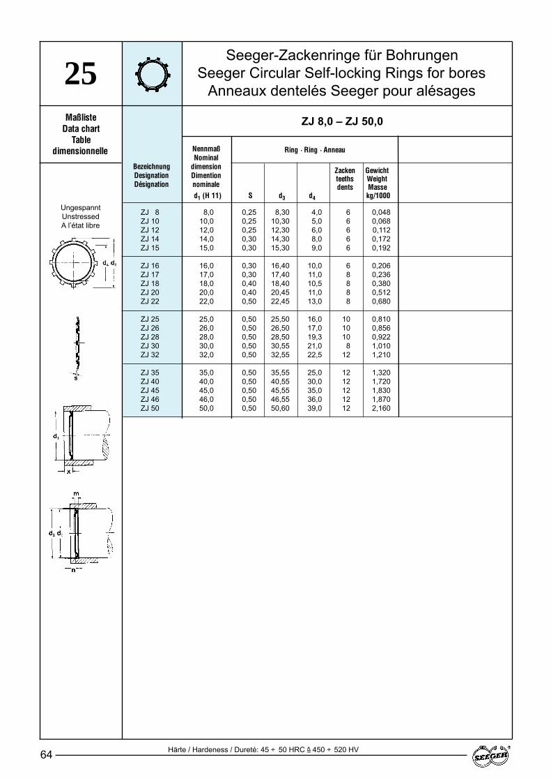
Seeger-Zackenringe für BohrungenSeeger Circular Self-locking Rings for bores
Anneaux dentelés Seeger pour alésages
64
MaßlisteData chart
Tabledimensionnelle
BezeichnungDesignationDésignation
ZJ 8,0 – ZJ 50,0
Ring · Ring · Anneau
25
Härte / Hardeness / Dureté: 45 ÷ 50 HRC ^ 450 ÷ 520 HV=
UngespanntUnstressedA l’état libre
ZJ 8 8,0 0,25 8,30 4,0 6 0,048ZJ 10 10,0 0,25 10,30 5,0 6 0,068ZJ 12 12,0 0,25 12,30 6,0 6 0,112ZJ 14 14,0 0,30 14,30 8,0 6 0,172ZJ 15 15,0 0,30 15,30 9,0 6 0,192
ZJ 16 16,0 0,30 16,40 10,0 6 0,206ZJ 17 17,0 0,30 17,40 11,0 8 0,236ZJ 18 18,0 0,40 18,40 10,5 8 0,380ZJ 20 20,0 0,40 20,45 11,0 8 0,512ZJ 22 22,0 0,50 22,45 13,0 8 0,680
ZJ 25 25,0 0,50 25,50 16,0 10 0,810ZJ 26 26,0 0,50 26,50 17,0 10 0,856ZJ 28 28,0 0,50 28,50 19,3 10 0,922ZJ 30 30,0 0,50 30,55 21,0 8 1,010ZJ 32 32,0 0,50 32,55 22,5 12 1,210
ZJ 35 35,0 0,50 35,55 25,0 12 1,320ZJ 40 40,0 0,50 40,55 30,0 12 1,720ZJ 45 45,0 0,50 45,55 35,0 12 1,830ZJ 46 46,0 0,50 46,55 36,0 12 1,870ZJ 50 50,0 0,50 50,60 39,0 12 2,160
NennmaßNominal
dimensionDimention nominale
Toleranz Zacken GewichtTolerance teeths WeightTolérance dents Masse
d1 (H 11) S d3 d4 max kg/1000
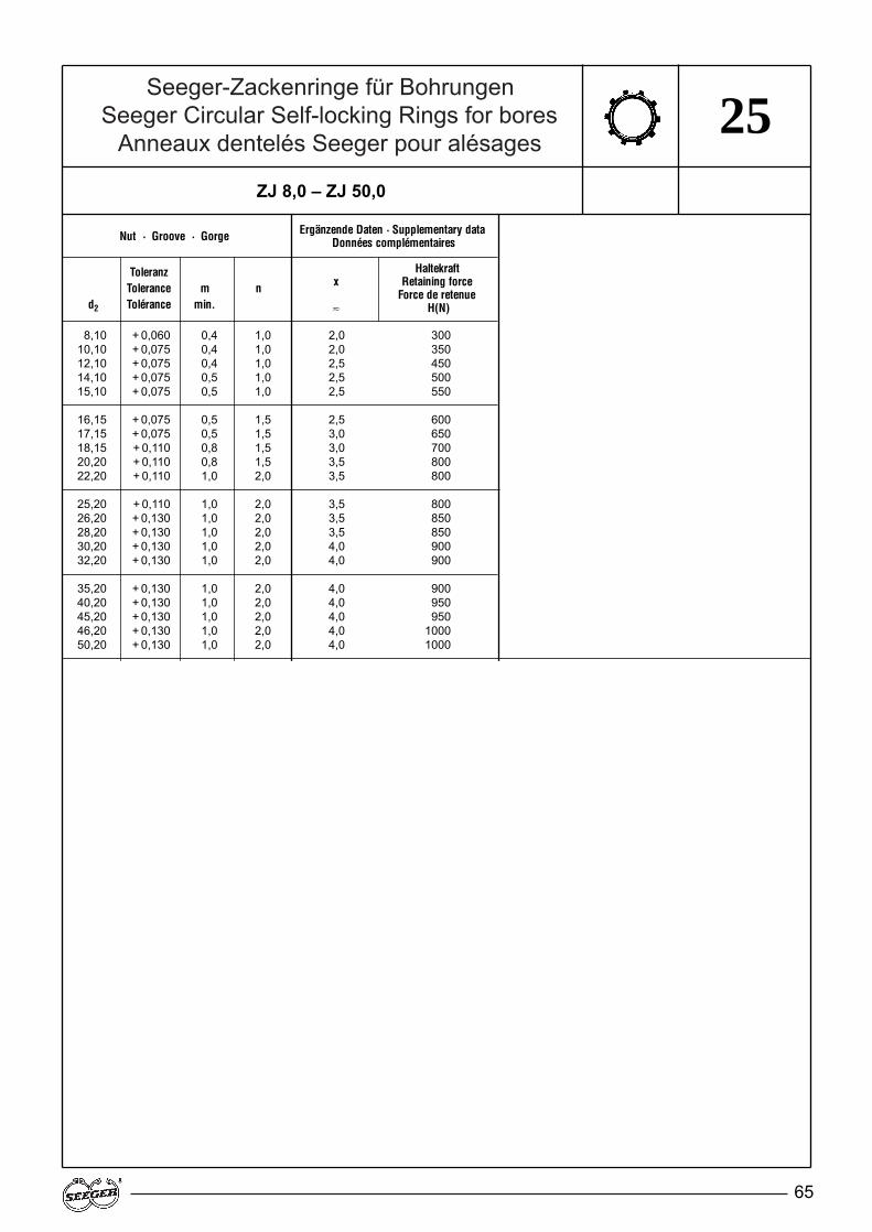
Seeger-Zackenringe für BohrungenSeeger Circular Self-locking Rings for bores
Anneaux dentelés Seeger pour alésages
65
ToleranzTolerance m n
d2 Tolérance min.
ZJ 8,0 – ZJ 50,0
25
Nut · Groove · Gorge Ergänzende Daten · Supplementary dataDonnées complémentaires
Haltekraftx Retaining force
Force de retenue≈ H(N)
8,10 + 0,060 0,4 1,0 2,0 30010,10 + 0,075 0,4 1,0 2,0 35012,10 + 0,075 0,4 1,0 2,5 45014,10 + 0,075 0,5 1,0 2,5 50015,10 + 0,075 0,5 1,0 2,5 550
16,15 + 0,075 0,5 1,5 2,5 60017,15 + 0,075 0,5 1,5 3,0 65018,15 + 0,110 0,8 1,5 3,0 70020,20 + 0,110 0,8 1,5 3,5 80022,20 + 0,110 1,0 2,0 3,5 800
25,20 + 0,110 1,0 2,0 3,5 80026,20 + 0,130 1,0 2,0 3,5 85028,20 + 0,130 1,0 2,0 3,5 85030,20 + 0,130 1,0 2,0 4,0 90032,20 + 0,130 1,0 2,0 4,0 900
35,20 + 0,130 1,0 2,0 4,0 90040,20 + 0,130 1,0 2,0 4,0 95045,20 + 0,130 1,0 2,0 4,0 95046,20 + 0,130 1,0 2,0 4,0 100050,20 + 0,130 1,0 2,0 4,0 1000
66
4.Gruppe 3:Radialmontierbare Seeger-Ringe
Werkstoff: Federstahl
Härte: Siehe Maßlisten
Oberflächenschutz:nach Wahl des Herstellers– phosphatiert und geölt
Sonderausführung auf Anfrage:– blank geölt– verzinkt– Bronze CuSn8– korrosionsbeständiger Stahlsiehe Seite 113
Zur Beachtung:Die Werte in den Maßlisten für dieDicke s gelten für Ringe in phospha-tierter, geschwärzter oder blanker Aus-führung. Bei galvanischen Überzügenvergrößern sich diese Maße entspre-chend den Schichtdicken.
Beschreibung der Ringe:Siehe Seite 8 – 9
Berechnung der Tragfähigkeit:Siehe Seite 119
Montage: Siehe Seite 132 – 133
DIN 6799 Tragfähigkeit der Nut FN:Die FN-Werte beziehen sich auf denWellendurchmesser d1'. Bei von d1'abweichendem Wellendurchmesser d1errechnet sich die Tragfähigkeit derNut FN' aus:
Group 3:Seeger-Rings for radial assembly
Material: Spring steel
Hardness: See data chart
Surface protection:To manufacturer's choice– Phosphated and oiled
Special versionsPlease enquire:– non-coated and oiled– zinc-plated– bronze CuSn8– corrosion-resistant steelsee Page 113
Please note:The values in the data charts for thethickness s apply to phosphated,blackened or self-finish rings. If galva-nic coatings are used, these valuesare increased corresponding to thecoating thicknesses involved.
Description of rings:See Page 8 – 9
Load bearing capacity calculations:See Page 119
Assembly: See Page 132 – 133
DIN 6799 load bearing capacity ofthe groove FN:The FN values refer to the shaft dia-meter d1'. If the shaft diameter d 1 de-viates from d1', the load bearing capa-city of the groove FN' is calculated asfollows:
Groupe 3:Segments d'arrêt Seeger à montage radial
Matière: Acier à ressort
Dureté: Voir tables dimensionnelles
Protection de surface:au choix du fabricant– phosphatée et huilée
Exécutions spéciales sur demande:– polie et huilée– zinguée– bronze CuSn8– acier résistant à la corrosionvoir page 113
Remarque:Les valeurs indiquées dans les tablesdimensionnelles pour l'épaisseur 's'sont valables pour des exécutionsphosphatées, noircies ou polies. Encas de traitement de surface, cette di-mension doit être augmentée del'épaisseur du revêtement.
Description des segments d'arrêt:Voir page 8 – 9
Calcul de la capacité de charge:Voir page 119
Montage: Voir page 132 – 133
DIN 6799 capacité de charge de lagorge FN:Les valeurs FN correspondent au dia-mètre de l'arbre d1'. Dans le cas où lediamètre d1 diffère de d1', la capacitéde charge de la gorge F N' se calculede la manière suivante:
Maßliste Seite BezeichnungData Chart Page DesignationTable dim. Page Désignation
32 68 – 69 Seeger-Sicherungsscheiben DIN 6799 / Seeger Retaining Rings to DIN 6799 /Colliers d'épaulement Seeger DIN 6799 RA...
33 70 – 71 Seeger-Halbmondringe / Seeger Crescent Rings / Croissants Seeger H...
FN' = F N d1 – d2d1' – d2
MaßlistenData charts
Tables dimensionnelles

67
4.
Seeger-Box DIN 6799
Seeger-Sicherungsscheiben in derpraktischen Klarsicht-Kunststoffbox.Übersichtlich sortiert, leicht nachfüll-bar, bequem zu entnehmen. Die be-darfsorientierte Sortierung in denGrößen 1.9 bis 10 macht diesesSortiment so wirtschaftlich.
Seeger box to DIN 6799
Seeger retaining rings in a practicaltransparent plastic box. Clearly arran-ged, easy to refill and allowing conve-nient removal. This assortment is soeconomical because it is arranged ac-cording to requirements in sizes from1,9 to 10.
Coffret Seeger DIN 6799
Le coffret en matière plastique trans-parente est idéal pour le rangementdes colliers d'épaulement Seeger enatelier et dans l'entreprise. Les colliersd'épaulement disposés de façon trèsclaire peuvent en être retirés d'un seulgeste et être complétés à volonté. Laclassification des colliers compte tenudes besoins (tailles 1,9 à10) confèresa rentabilité à cet assortiment.
MaßlistenData charts
Tables dimensionnelles
Nut-Durchmesser StückzahlGroove diameter Quantity
Diamètre de gorge Quantité
1,9 500
2,3 500
3,2 500
4,0 500
5,0 300
6,0 200
7,0 100
8,0 100
9,0 50
10,0 50

NennmaßNominal
dimensionDimention nominale
Seeger-SicherungsscheibenSeeger Retaining Rings
Colliers d’épaulement Seeger
68
MaßlisteData chart
Tabledimensionnelle
d1 Toleranz Toleranz Gew.von bis Tolerance Tolerance Weightfrom to Tolérance d 4 Tolérance Masse
d2 de a s max. a ± JT 10 kg/1000
BezeichnungDesignationDésignation
RA 1,2 – RA 24,0 / DIN 6799
32
RA 1,2 1,2 1,4 2,0 0,30 ± 0,02 2,90 1,01 ± 0,040 0,009RA 1,5 1,5 2,0 2,5 0,40 ± 0,02 3,90 1,28 ± 0,040 0,021RA 1,9 1,9 2,5 3,0 0,50 ± 0,02 4,40 1,61 ± 0,040 0,040RA 2,3 2,3 3,0 4,0 0,60 ± 0,02 5,90 1,94 ± 0,040 0,069RA 3,2 3,2 4,0 5,0 0,60 ± 0,02 6,90 2,70 ± 0,040 0,088
RA 4,0 4,0 5,0 7,0 0,70 ± 0,02 8,85 3,34 ± 0,048 0,158RA 5,0 5,0 6,0 8,0 0,70 ± 0,02 10,85 4,11 ± 0,048 0,236RA 6,0 6,0 7,0 9,0 0,70 ± 0,02 11,80 5,26 ± 0,048 0,255RA 7,0 7,0 8,0 11,0 0,90 ± 0,02 13,80 5,84 ± 0,048 0,474RA 8,0 8,0 9,0 12,0 1,00 ± 0,03 15,75 6,52 ± 0,058 0,660
RA 9,0 9,0 10,0 14,0 1,10 ± 0,03 18,20 7,63 ± 0,058 1,000RA 10,0 10,0 11,0 15,0 1,20 ± 0,03 19,70 8,32 ± 0,058 1,120RA 12,0 12,0 13,0 18,0 1,30 ± 0,03 22,70 10,45 ± 0,070 1,770RA 15,0 15,0 16,0 24,0 1,50 ± 0,03 28,70 12,61 ± 0,070 3,370RA 19,0 19,0 20,0 31,0 1,75 ± 0,03 36,50 15,92 ± 0,070 6,420
RA 24,0 24,0 25,0 38,0 2,00 ± 0,03 43,50 21,88 ± 0,084 8,550
AnwendungsbereichApplication range
Domaine d’application
SicherungsscheibeRetaining ring
Collier
Härte / Hardeness / Dureté: 46 ÷ 54 HRC ^ 470 ÷ 545 HV=
Auch in magazinierter Ausführunglieferbar. Siehe jeweils gültigeSeeger-Preisliste.
Ringspender und Greifer fürSeeger-Sicherungsscheiben RAsiehe Seite 111
Also available in magazinedesign. See relevant valid Seegerprice list.
Ring dispensers and applicatorsfor Seeger Retaining Rings seepage 111
Livrable également empilées surtige. Se reporter au tarif Seegercorrespondant en vigueur.
Distributeurs et fourchettes depose pour colliers d’épaulementSeeger RA, voir page 111
UngespanntUnstressedA l’état libre

69
Nut · Groove · Gorge Ergänzende Daten · Supplementary data · Données complémentaires
bei GreiferToleranz F N with FR FRg nabl. Applicator
Tolerance m d 42 avec d1 x1000 Fourchette d2 Tolérance min. n kN kN g kN (1/min.) de pose
Seeger-SicherungsscheibenSeeger-Rings for shafts
Segments extérieurs Seeger32
RA 1,2 – RA 24,0 / DIN 6799
1,2 – 0,060 0,34 3,0 0,6 0,04 1,5 0,12 0,4 0,061,5 – 0,060 0,44 4,0 0,8 0,07 2,0 0,22 0,6 0,111,9 – 0,060 0,54 4,5 1,0 0,10 2,5 0,35 0,7 0,172,3 – 0,060 0,64 6,0 1,0 0,15 3,0 0,50 0,9 0,243,2 – 0,075 0,64 7,0 1,0 0,22 4,0 0,65 0,9 0,32
4,0 – 0,075 0,74 9,0 1,2 0,25 5,0 0,95 1,0 0,475,0 – 0,075 0,74 11,0 1,2 0,90 7,0 1,15 1,0 0,606,0 – 0,075 0,74 12,0 1,2 1,10 8,0 1,35 1,1 0,707,0 – 0,090 0,94 14,0 1,5 1,25 9,0 1,80 1,3 1,008,0 – 0,090 1,05 16,0 1,8 1,42 10,0 2,50 1,5 1,25
9,0 – 0,090 1,15 18,5 2,0 1,60 11,0 3,00 1,6 1,5010,0 – 0,090 1,25 20,0 2,0 1,70 12,0 3,50 1,8 1,7512,0 – 0,110 1,35 23,0 2,5 3,10 15,0 4,70 1,9 2,3015,0 – 0,110 1,55 29,0 3,0 7,00 20,0 7,80 2,2 3,3019,0 – 0,130 1,80 37,0 3,5 10,00 25,0 11,00 2,5 3,60
24,0 – 0,130 2,05 44,0 4,0 13,00 30,0 15,00 3,0 4,00
47 GRA 1,242 GRA 1,540 GRA 1,938 GRA 2,335 GRA 3,2
32 GRA 428 GRA 525 GRA 622 GRA 720 GRA 8
17 GRA 915 GRA 1013 –11 –8 –
6 –
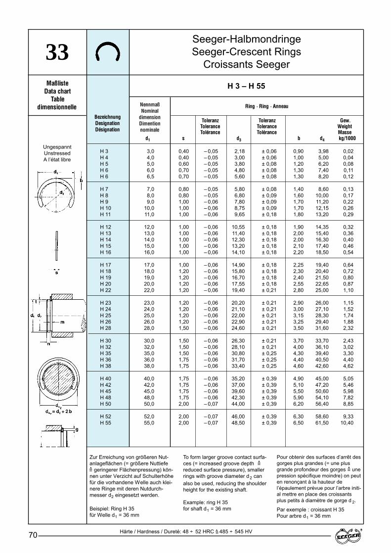
NennmaßNominal
dimensionDimention nominale
Seeger-HalbmondringeSeeger-Crescent Rings
Croissants Seeger
70
33Maßliste
Data chartTable
dimensionnelle
Toleranz Toleranz Gew.Tolerance Tolerance WeightTolérance Tolérance Masse
d1 s d3 b d4 kg/1000
BezeichnungDesignationDésignation
H 3 – H 55
Ring · Ring · Anneau
H 3 3,0 0,40 – 0,05 2,18 ± 0,06 0,90 3,98 0,02H 4 4,0 0,40 – 0,05 3,00 ± 0,06 1,00 5,00 0,04H 5 5,0 0,60 – 0,05 3,80 ± 0,08 1,20 6,20 0,08H 6 6,0 0,70 – 0,05 4,80 ± 0,08 1,30 7,40 0,11H 6 6,5 0,70 – 0,05 5,60 ± 0,08 1,30 8,20 0,12
H 7 7,0 0,80 – 0,05 5,80 ± 0,08 1,40 8,60 0,13H 8 8,0 0,80 – 0,05 6,80 ± 0,09 1,60 10,00 0,17H 9 9,0 1,00 – 0,06 7,80 ± 0,09 1,70 11,20 0,22H 10 10,0 1,00 – 0,06 8,75 ± 0,09 1,70 12,15 0,26H 11 11,0 1,00 – 0,06 9,65 ± 0,18 1,80 13,20 0,29
H 12 12,0 1,00 – 0,06 10,55 ± 0,18 1,90 14,35 0,32H 13 13,0 1,00 – 0,06 11,40 ± 0,18 2,00 15,40 0,36H 14 14,0 1,00 – 0,06 12,30 ± 0,18 2,00 16,30 0,40H 15 15,0 1,00 – 0,06 13,20 ± 0,18 2,10 17,40 0,46H 16 16,0 1,00 – 0,06 14,10 ± 0,18 2,20 18,50 0,54
H 17 17,0 1,00 – 0,06 14,90 ± 0,18 2,25 19,40 0,64H 18 18,0 1,20 – 0,06 15,80 ± 0,18 2,30 20,40 0,72H 19 19,0 1,20 – 0,06 16,70 ± 0,18 2,40 21,50 0,80H 20 20,0 1,20 – 0,06 17,55 ± 0,18 2,55 22,65 0,87H 22 22,0 1,20 – 0,06 19,40 ± 0,21 2,80 25,00 1,10
H 23 23,0 1,20 – 0,06 20,20 ± 0,21 2,90 26,00 1,15H 24 24,0 1,20 – 0,06 21,10 ± 0,21 3,00 27,10 1,52H 25 25,0 1,20 – 0,06 22,00 ± 0,21 3,15 28,30 1,74H 26 26,0 1,20 – 0,06 22,90 ± 0,21 3,25 29,40 1,88H 28 28,0 1,50 – 0,06 24,60 ± 0,21 3,50 31,60 2,32
H 30 30,0 1,50 – 0,06 26,30 ± 0,21 3,70 33,70 2,43H 32 32,0 1,50 – 0,06 28,10 ± 0,21 4,00 36,10 3,02H 35 35,0 1,50 – 0,06 30,80 ± 0,25 4,30 39,40 3,30H 36 36,0 1,75 – 0,06 31,70 ± 0,25 4,40 40,50 4,40H 38 38,0 1,75 – 0,06 33,40 ± 0,25 4,60 42,60 4,62
H 40 40,0 1,75 – 0,06 35,20 ± 0,39 4,90 45,00 5,05H 42 42,0 1,75 – 0,06 37,00 ± 0,39 5,10 47,20 5,46H 45 45,0 1,75 – 0,06 39,60 ± 0,39 5,50 50,60 5,98H 48 48,0 1,75 – 0,06 42,30 ± 0,39 5,90 54,10 7,82H 50 50,0 2,00 – 0,07 44,00 ± 0,39 6,20 56,40 8,85
H 52 52,0 2,00 – 0,07 46,00 ± 0,39 6,30 58,60 9,33H 55 55,0 2,00 – 0,07 48,50 ± 0,39 6,50 61,50 10,40
UngespanntUnstressedA l’état libre
Härte / Hardness / Dureté: 48 ÷ 52 HRC ^ 485 ÷ 545 HV=
Zur Erreichung von größeren Nut-anlageflächen (= größere Nuttiefe=̂ geringerer Flächenpressung) kön-nen unter Verzicht auf Schulterhöhefür die vorhandene Welle auch klei-nere Ringe mit deren Nutdurch-messer d2 eingesetzt werden.
Beispiel: Ring H 35 für Welle d1 = 36 mm
To form larger groove contact surfa-ces (= increased groove depth =̂reduced surface pressure), smallerrings with groove diameter d2 canalso be used, reducing the shoulderheight for the existing shaft.
Example: ring H 35for shaft d1 = 36 mm
Pour obtenir des surfaces d’arrêt desgorges plus grandes (= une plusgrande profondeur des gorges =̂ unepression spécifique moindre) on peuten renonçant à la hauteur del’épaulement prévue pour l’arbre initi-al mettre en place des croissantsplus petits à diamètre de gorge d 2.
Par exemple : croissant H 35 Pour arbre d1 = 36 mm

Seeger-HalbmondringeSeeger-Crescent Rings
Croissants Seeger
71
33
Nut · Groove · Gorge Ergänzende Daten · Supplementary data · Données complémentaires
Toleranz GreiferTolerance m* F N FR FRg nabl. ApplicatorTolérance x1000 Fourchette
d2* min. t d 42n (kN) (kN) g (kN) (1/min) de pose
* Siehe Abschnitt 8, Seite 128 · * See section 8, page 128 · * V oir paragraphe 8, page 128
H 3 – H 55
95 GRH 390 GRH 488 GRH 580 GRH 676 –
69 GRH 767 GRH 858 GRH 950 GRH 1040 GRH 11
35 GRH 1230 GRH 1327 GRH 1425 GRH 1524 GRH 16
23 GRH 1721 GRH 1821 GRH 1920 GRH 2017 GRH 22
15 GRH 2315 GRH 2415 GRH 2515 GRH 2613 –
13 –13 –11 –10 –10 –
9 –9 –8 –8 –7 –
7 –7 –
2,3 – 0,07 0,44 0,35 4,1 1,0 0,24 0,50 0,40 0,403,2 – 0,07 0,44 0,40 5,2 1,2 0,37 0,50 0,40 0,404,0 – 0,07 0,64 0,50 6,4 1,5 0,58 1,10 0,60 0,705,0 – 0,07 0,74 0,50 7,6 1,5 0,72 1,65 0,70 1,105,8 – 0,07 0,74 0,35 8,4 1,0 0,55 1,70 0,70 1,05
6,0 – 0,09 0,85 0,50 8,8 1,5 0,85 2,20 0,80 1,307,0 – 0,09 0,85 0,50 10,2 1,5 0,98 2,20 0,80 1,308,0 – 0,09 1,10 0,50 11,4 1,5 1,10 3,50 1,00 2,009,0 – 0,09 1,10 0,50 12,4 1,5 1,24 3,70 1,00 2,00
10,0 – 0,11 1,10 0,50 13,6 1,5 1,35 4,00 1,00 2,00
10,9 – 0,11 1,10 0,55 14,7 1,7 1,65 4,20 1,00 2,0011,8 – 0,11 1,10 0,60 15,8 1,8 1,90 4,50 1,00 2,0012,7 – 0,11 1,10 0,65 16,7 2,0 2,20 5,00 1,00 2,0013,6 – 0,11 1,10 0,70 17,8 2,1 2,60 5,50 1,00 2,0014,5 – 0,11 1,10 0,75 18,9 2,3 3,00 5,80 1,00 2,00
15,4 – 0,11 1,10 0,80 19,9 2,4 3,40 6,00 1,00 2,0016,3 – 0,11 1,30 0,85 20,9 2,6 3,70 8,50 1,20 2,8017,2 – 0,11 1,30 0,90 22,0 2,7 4,30 9,00 1,20 2,8018,1 – 0,21 1,30 0,95 23,2 2,9 4,70 9,40 1,20 3,0019,9 – 0,21 1,30 1,05 25,5 3,2 5,70 10,00 1,20 3,00
20,8 – 0,21 1,30 1,10 26,6 3,3 6,20 10,50 1,20 3,2021,7 – 0,21 1,30 1,15 27,7 3,5 6,80 11,00 1,20 3,2022,6 – 0,21 1,30 1,20 28,9 3,6 7,50 11,50 1,20 3,2023,5 – 0,21 1,30 1,25 30,0 3,8 8,00 12,00 1,20 3,2025,2 – 0,21 1,60 1,40 32,2 4,2 9,70 16,50 1,50 5,50
27,0 – 0,21 1,60 1,50 34,4 4,5 11,00 17,00 1,50 5,6028,8 – 0,21 1,60 1,60 36,8 4,6 12,50 18,00 1,50 5,8031,5 – 0,25 1,60 1,75 40,1 5,3 15,00 20,00 1,50 5,8032,4 – 0,25 1,85 1,80 41,2 5,4 16,00 25,00 1,75 8,3034,2 – 0,25 1,85 1,90 43,4 5,7 17,50 26,00 1,75 8,50
36,0 – 0,25 1,85 2,00 45,8 6,0 20,00 27,50 1,75 8,8037,8 – 0,25 1,85 2,10 48,0 6,3 21,50 28,00 1,75 8,9040,5 – 0,25 1,85 2,25 51,5 6,8 25,00 30,00 1,75 9,0043,2 – 0,25 1,85 2,40 55,0 7,2 28,00 32,00 1,75 9,045,0 – 0,25 2,15 2,50 57,4 7,5 31,00 39,50 2,00 12,00
47,0 – 0,25 2,15 2,50 59,6 7,5 32,00 41,00 2,00 12,0050,0 – 0,25 2,15 2,50 63,0 7,5 34,00 43,00 2,00 12,00

72
NotizenNotesNotes
73
4.
Gruppe 4:Seeger-Ringe zum Ausgleich axialen Spieles
Werkstoff: Federstahl
Härte: Siehe Maßlisten
Oberflächenschutz:nach Wahl des Herstellers– phosphatiert und geölt– geschwärzt und geölt
Sonderausführungauf Anfrage:– blank geölt– verzinkt
Zur Beachtung:Die Werte in den Maßlisten für dieDicke s gelten für Ringe in phospha-tierter, geschwärzter oder blankerAusführung. Bei anderen Oberflächen-beschichtungen vergrößern sich dieseMaße entsprechend der Schichtdicke.
Beschreibung der Ringe:Siehe Seite 9 – 10
Berechnung der Tragfähigkeit:Siehe Seite 119
Ausgleich Axialspiel:Voraussetzung für die spielfreie Fest-legung eines Maschinenteiles (odermehrerer) ist, daß die Summe derToleranzen ∆ der Axialmaße des fest-zulegenden Teiles (oder der Teile) desSeeger-Ringes und des Nuteinsticheskleiner ist als die Ausgleichsmöglich-keit des Seeger-Ringes. Gegebenen-falls ist das Axialspiel mit Hilfe vonPaßscheiben zu reduzieren.
Anwendung:Seeger-L-Ringe Seite 75Seeger-Keil-Ringe Seite 78/79
Group 4:Seeger-Rings for compensating axial play
Material: Spring steel
Hardness: See data charts
Surface protection:To manufacturer's choice– phosphated and oiled– bleckened and oiled
Special versionsPlease enquire:– non-coated and oiled– zinc-plated
Please note:The values given in the data charts forthe thickness s apply to phosphated,blackened or self-finish rings. In theevent of different surface coatings, the-se dimensions will be increased by thecorresponding coating thickness.
Description of the rings:See Page 9 – 10
Load bearing capacity calculation:See Page 119
Compensating axial play:A precondition for play-free securing ofa machine part (or of several) is thatthe total of tolerances ∆ of the axial di-mensions of the part to be secured (orof the parts), of the Seeger ring and ofthe cut groove is less than the Seegerring's compensation capabilities. If ne-cessary, reduce axial play using shimwashers.
Applications:Seeger-L-Rings Page 75Seeger Bevelled Rings Page 78/79
Groupe 4:Segments d'arrêt Seeger compensant le jeu axial
Matière: Acier à ressort
Dureté: Voir tables dimensionnelles
Protection de surface:au choix du fabricant– phosphatée et huilée– noircie et huilée
Exécutions spéciales sur demande:– polie et huilée– zinguée
Remarque:Les valeurs indiquées dans les tablesdimensionnelles pour l'épaisseur 's'sont valables pour des exécutionsphosphatées, noircies ou polies. Encas de traitement de surface, cette di-mension doit être augmentée del'épaisseur du revêtement.
Description des segments d'arrêt:Voir page 9 – 10
Calcul de la capacité de charge:Voir page 119
Compensation du jeu axial:Pour une fixation sans jeu d'une ouplusieurs pièces de machine, il est in-dispensable que la somme des tolé-rances ∆ sur les dimensions axiales dela ou des pièces à fixer, du segmentd'arrêt Seeger et de la gorge soit in-férieure aux possibilités d'absorptionde jeu qu'offre le segment d'arrêtSeeger.
Applications:Segments d'arrêt Seeger type L page 75Segments chanfreinés Seeger page 78/79
Maßliste Seite BezeichnungData Chart Page DesignationTable dim. Page Désignation
40/41 74 – 77 Seeger-L-Ringe / Seeger-L-Rings / Segments d'arrêt Seeger type L AL.../JL...
45 78 – 79 Seeger-Keil-Ringe / Seeger Bevelled Rings / Segments chanfreinés JB...
MaßlistenData charts
Tables dimensionnelles
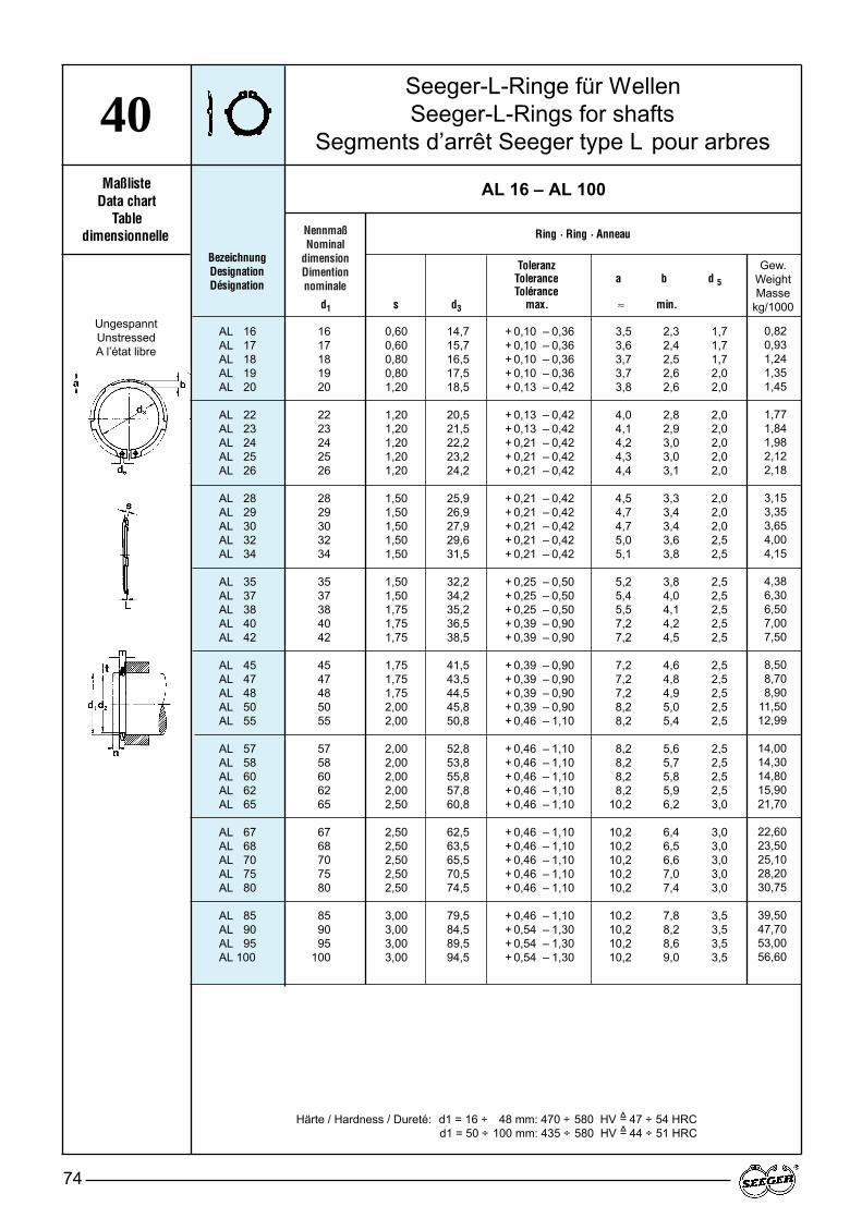
NennmaßNominal
dimensionDimention nominale
Seeger-L-Ringe für WellenSeeger-L-Rings for shafts
Segments d’arrêt Seeger type L pour arbres
74
40Maßliste
Data chartTable
dimensionnelle
Toleranz ToleranzTolerance Tolerance a b d 5Tolérance Tolérance
d1 s d3 max. ≈ min.
BezeichnungDesignationDésignation
AL 16 – AL 100
Ring · Ring · Anneau
AL 16 16 0,60 14,7 + 0,10 – 0,36 3,5 2,3 1,7AL 17 17 0,60 15,7 + 0,10 – 0,36 3,6 2,4 1,7AL 18 18 0,80 16,5 + 0,10 – 0,36 3,7 2,5 1,7AL 19 19 0,80 17,5 + 0,10 – 0,36 3,7 2,6 2,0AL 20 20 1,20 18,5 + 0,13 – 0,42 3,8 2,6 2,0
AL 22 22 1,20 20,5 + 0,13 – 0,42 4,0 2,8 2,0AL 23 23 1,20 21,5 + 0,13 – 0,42 4,1 2,9 2,0AL 24 24 1,20 22,2 + 0,21 – 0,42 4,2 3,0 2,0AL 25 25 1,20 23,2 + 0,21 – 0,42 4,3 3,0 2,0AL 26 26 1,20 24,2 + 0,21 – 0,42 4,4 3,1 2,0
AL 28 28 1,50 25,9 + 0,21 – 0,42 4,5 3,3 2,0AL 29 29 1,50 26,9 + 0,21 – 0,42 4,7 3,4 2,0AL 30 30 1,50 27,9 + 0,21 – 0,42 4,7 3,4 2,0AL 32 32 1,50 29,6 + 0,21 – 0,42 5,0 3,6 2,5AL 34 34 1,50 31,5 + 0,21 – 0,42 5,1 3,8 2,5
AL 35 35 1,50 32,2 + 0,25 – 0,50 5,2 3,8 2,5AL 37 37 1,50 34,2 + 0,25 – 0,50 5,4 4,0 2,5AL 38 38 1,75 35,2 + 0,25 – 0,50 5,5 4,1 2,5AL 40 40 1,75 36,5 + 0,39 – 0,90 7,2 4,2 2,5AL 42 42 1,75 38,5 + 0,39 – 0,90 7,2 4,5 2,5
AL 45 45 1,75 41,5 + 0,39 – 0,90 7,2 4,6 2,5AL 47 47 1,75 43,5 + 0,39 – 0,90 7,2 4,8 2,5AL 48 48 1,75 44,5 + 0,39 – 0,90 7,2 4,9 2,5AL 50 50 2,00 45,8 + 0,39 – 0,90 8,2 5,0 2,5AL 55 55 2,00 50,8 + 0,46 – 1,10 8,2 5,4 2,5
AL 57 57 2,00 52,8 + 0,46 – 1,10 8,2 5,6 2,5AL 58 58 2,00 53,8 + 0,46 – 1,10 8,2 5,7 2,5AL 60 60 2,00 55,8 + 0,46 – 1,10 8,2 5,8 2,5AL 62 62 2,00 57,8 + 0,46 – 1,10 8,2 5,9 2,5AL 65 65 2,50 60,8 + 0,46 – 1,10 10,2 6,2 3,0
AL 67 67 2,50 62,5 + 0,46 – 1,10 10,2 6,4 3,0AL 68 68 2,50 63,5 + 0,46 – 1,10 10,2 6,5 3,0AL 70 70 2,50 65,5 + 0,46 – 1,10 10,2 6,6 3,0AL 75 75 2,50 70,5 + 0,46 – 1,10 10,2 7,0 3,0AL 80 80 2,50 74,5 + 0,46 – 1,10 10,2 7,4 3,0
AL 85 85 3,00 79,5 + 0,46 – 1,10 10,2 7,8 3,5AL 90 90 3,00 84,5 + 0,54 – 1,30 10,2 8,2 3,5AL 95 95 3,00 89,5 + 0,54 – 1,30 10,2 8,6 3,5AL 100 100 3,00 94,5 + 0,54 – 1,30 10,2 9,0 3,5
UngespanntUnstressedA l’état libre
Härte / Hardness / Dureté: d1 = 16 ÷ 48 mm: 470 ÷ 580 HV ^ 47 ÷ 54 HRCHärte / Hardness / Dureté: d1 = 50 ÷ 100 mm: 435 ÷ 580 HV ^ 44 ÷ 51 HRC
==
Gew.WeightMasse
kg/1000
0,820,931,241,351,45
1,771,841,982,122,18
3,153,353,654,004,15
4,386,306,507,007,50
8,508,708,90
11,5012,99
14,0014,3014,8015,9021,70
22,6023,5025,1028,2030,75
39,5047,7053,0056,60
Seeger-L-Ringe für WellenSeeger-L-Rings for shafts
Segments d’arrêt Seeger type L pour arbres
75
40
Nut · Groove · Gorge Ergänzende Daten · Supplementary data · Données complémentaires
ToleranzTolerance m* F N FR FRg FLmax. L C
d2 Tolérance min. n (kN) (kN) g (kN) (kN) min. u (kN/mm)
* Siehe Abschnitt 8, Seite 128 · * See section 8, page 128 · * V oir paragraphe 8, page 128
AL 16 – AL 100
15,2 – 0,11 0,70 1,2 3,26 2,20 1,0 0,70 0,13 0,35 0,05 0,4316,2 – 0,11 0,70 1,2 3,46 2,10 1,0 0,65 0,12 0,35 0,05 0,3817,0 – 0,11 0,90 1,5 4,58 5,04 1,5 1,12 0,25 0,35 0,05 0,8218,0 – 0,11 0,90 1,5 4,85 5,04 1,5 1,13 0,24 0,35 0,05 0,8119,0 – 0,15 1,30 1,5 5,06 17,10 1,5 3,85 0,77 0,35 0,05 2,58
21,0 – 0,15 1,30 1,5 5,65 16,90 1,5 3,80 0,68 0,35 0,05 2,2722,0 – 0,15 1,30 1,5 5,90 16,60 1,5 3,80 0,65 0,35 0,05 2,1722,9 – 0,21 1,30 1,6 6,75 16,10 1,5 3,65 0,70 0,40 0,05 1,9923,9 – 0,21 1,30 1,6 7,05 16,20 1,5 3,70 0,66 0,40 0,05 1,8924,9 – 0,21 1,30 1,6 7,34 16,10 1,5 3,70 0,62 0,40 0,05 1,78
26,6 – 0,21 1,60 2,1 10,00 32,10 1,5 7,50 0,99 0,40 0,10 3,2827,6 – 0,21 1,60 2,1 10,37 31,80 1,5 7,45 0,91 0,40 0,10 3,0328,6 – 0,21 1,60 2,1 10,70 32,10 1,5 7,65 0,90 0,40 0,10 2,9730,3 – 0,25 1,60 2,5 13,85 31,20 2,0 5,55 0,90 0,45 0,10 2,5732,3 – 0,25 1,60 2,5 14,72 31,30 2,0 5,60 0,86 0,45 0,10 2,45
33,0 – 0,25 1,60 3,0 17,80 30,80 2,0 5,50 0,93 0,50 0,10 2,3235,0 – 0,25 1,60 3,0 18,80 30,00 2,0 5,40 0,83 0,50 0,10 2,0836,0 – 0,25 1,85 3,0 19,30 49,50 2,0 9,10 1,30 0,50 0,10 3,2637,5 – 0,25 1,85 3,8 25,30 51,00 2,0 9,50 1,00 0,60 0,10 1,9839,5 – 0,25 1,85 3,8 26,70 50,00 2,0 9,45 0,95 0,60 0,10 1,91
42,5 – 0,25 1,85 3,8 28,60 49,00 2,0 9,35 0,92 0,60 0,10 1,8644,5 – 0,25 1,85 3,8 30,00 49,50 2,0 9,50 0,92 0,60 0,10 1,8545,5 – 0,25 1,85 3,8 30,70 49,40 2,0 9,50 0,92 0,60 0,10 1,8447,0 – 0,25 2,15 4,5 38,00 73,30 2,0 14,40 1,33 0,80 0,15 2,0552,0 – 0,30 2,15 4,5 42,00 71,40 2,5 11,40 1,32 0,80 0,15 2,04
54,0 – 0,30 2,15 4,5 43,70 70,90 2,5 11,40 1,30 0,80 0,15 2,0155,0 – 0,30 2,15 4,5 44,30 71,10 2,5 11,50 1,30 0,80 0,15 2,0257,0 – 0,30 2,15 4,5 46,00 69,30 2,5 11,30 1,28 0,80 0,15 1,9759,0 – 0,30 2,15 4,5 47,50 69,30 2,5 11,40 1,28 0,80 0,15 1,9762,0 – 0,30 2,65 4,5 49,90 135,60 2,5 22,70 1,96 1,00 0,20 2,45
64,0 – 0,30 2,65 4,5 51,30 136,10 2,5 23,00 1,96 1,00 0,20 2,4565,0 – 0,30 2,65 4,5 52,20 135,90 2,5 23,10 1,95 1,00 0,20 2,4467,0 – 0,30 2,65 4,5 53,80 134,20 2,5 23,00 1,93 1,00 0,20 2,4172,0 – 0,30 2,65 4,5 57,60 130,00 2,5 22,80 1,88 1,00 0,20 2,3476,5 – 0,30 2,65 5,3 71,60 128,40 3,0 19,50 1,89 1,00 0,20 2,36
81,5 – 0,54 3,15 5,3 76,20 215,40 3,0 33,40 3,24 1,00 0,20 4,0586,5 – 0,54 3,15 5,3 80,80 217,20 3,0 34,40 3,21 1,00 0,20 4,0191,5 – 0,54 3,15 5,3 85,50 212,20 3,5 29,30 3,21 1,00 0,20 4,0096,5 – 0,54 3,15 5,3 90,00 206,40 3,5 29,00 3,18 1,00 0,20 3,97
amin. = bmax. + s1max. + u + smax.amax. = bmin. + ∆a
oder / or / ouamax. = bmin. + S1min. + L + smin.amin. = bmax. - ∆a
FL = C . ffmax. = L-ufmin. = L - (Σ∆ + u)
Für die Bemaßung gilt:The following applies to dimensions:Pour le calcul, procéder comme suit:
Σ∆ ≤ L-u
Anpresskraft:Pressure:Force de pression:
]
]
Maximale VorspannungMaximum prestressPression frontale maximum
Minimale VorspannungMinimum prestressPression frontale minimum
Zange PliersPince
ZGA–1ZGA–1ZGA–2ZGA–2ZGA–2
ZGA–2ZGA–2ZGA–2ZGA–2ZGA–2
ZGA–2ZGA–2ZGA–2ZGA–2ZGA–2
ZGA–2ZGA–2ZGA–2ZGA–3ZGA–3
ZGA–3ZGA–3ZGA–3ZGA–3ZGA–3
ZGA–3ZGA–3ZGA–3ZGA–3ZGA–3
ZGA–3ZGA–3ZGA–3ZGA–3ZGA–3
ZGA–4ZGA–4ZGA–4ZGA–4

Seeger-L-Ringe für BohrungenSeeger-L-Rings for bores
Segments d’arrêt Seeger type L pour alésages
76
41Maßliste
Data chartTable
dimensionnelleBezeichnungDesignationDésignation
JL 16 – JL 100
Ring · Ring · Anneau
JL 16 16 0,60 17,3 + 0,42 – 0,13 3,4 2,1 1,7JL 17 17 0,60 18,3 + 0,42 – 0,13 3,7 2,2 1,7JL 18 18 0,80 19,5 + 0,42 – 0,13 4,1 2,3 1,7JL 19 19 0,80 20,5 + 0,42 – 0,13 3,8 2,3 2,0JL 20 20 1,00 21,5 + 0,42 – 0,13 3,9 2,4 2,0
JL 21 21 1,00 22,5 + 0,42 – 0,13 4,0 2,4 2,0JL 22 22 1,00 23,5 + 0,42 – 0,13 4,0 2,6 2,0JL 23 23 1,20 24,6 + 0,42 – 0,13 4,1 2,6 2,0JL 24 24 1,20 25,9 + 0,42 – 0,21 4,2 2,6 2,0JL 25 25 1,20 26,9 + 0,42 – 0,21 4,4 2,8 2,0
JL 26 26 1,20 28,5 + 0,42 – 0,21 4,4 2,8 2,0JL 27 27 1,20 29,1 + 0,42 – 0,21 4,5 2,9 2,0JL 28 28 1,20 30,1 + 0,50 – 0,25 4,9 3,0 2,0JL 30 30 1,20 32,1 + 0,50 – 0,25 4,9 3,2 2,0JL 31 31 1,20 33,4 + 0,50 – 0,25 5,0 3,2 2,5
JL 32 32 1,20 34,4 + 0,50 – 0,25 5,1 3,3 2,5JL 33 33 1,20 35,5 + 0,50 – 0,25 5,1 3,3 2,5JL 34 34 1,50 36,5 + 0,50 – 0,25 5,3 3,4 2,5JL 35 35 1,50 37,8 + 0,50 – 0,25 5,5 3,6 2,5JL 36 36 1,50 38,8 + 0,50 – 0,25 5,6 3,6 2,5
JL 38 38 1,50 40,8 + 0,50 – 0,25 6,1 3,8 2,5JL 40 40 1,75 43,5 + 0,90 – 0,39 7,2 4,0 2,5JL 42 42 1,75 45,5 + 0,90 – 0,39 7,2 4,1 2,5JL 44 44 1,75 47,5 + 0,90 – 0,39 7,2 4,2 2,5JL 45 45 1,75 48,5 + 0,90 – 0,39 7,2 4,3 2,5
JL 47 47 1,75 50,5 + 1,10 – 0,46 7,2 4,5 2,5JL 48 48 1,75 51,5 + 1,10 – 0,46 7,2 4,5 2,5JL 50 50 2,00 54,2 + 1,10 – 0,46 8,2 4,7 2,5JL 52 52 2,00 56,2 + 1,10 – 0,46 8,2 4,7 2,5JL 55 55 2,00 59,2 + 1,10 – 0,46 8,2 5,1 2,5
JL 57 57 2,00 61,2 + 1,10 – 0,46 8,2 5,2 2,5JL 58 58 2,00 62,2 + 1,10 – 0,46 8,2 5,3 2,5JL 60 60 2,00 64,2 + 1,10 – 0,46 8,2 5,5 2,5JL 62 62 2,00 66,2 + 1,10 – 0,46 8,2 5,6 2,5JL 65 65 2,50 69,2 + 1,10 – 0,46 10,2 5,8 3,0
JL 67 67 2,50 71,5 + 1,10 – 0,46 10,2 6,0 3,0JL 68 68 2,50 72,5 + 1,10 – 0,46 10,2 6,1 3,0JL 70 70 2,50 74,5 + 1,10 – 0,46 10,2 6,2 3,0JL 72 72 2,50 76,5 + 1,10 – 0,46 10,2 6,4 3,0JL 75 75 2,50 79,5 + 1,10 – 0,46 10,2 6,6 3,0
JL 80 80 2,50 85,5 + 1,30 – 0,54 10,2 7,0 3,0JL 85 85 3,00 90,5 + 1,30 – 0,54 12,2 7,4 3,5JL 90 90 3,00 95,5 + 1,30 – 0,54 12,2 7,7 3,5JL 95 95 3,00 100,5 + 1,30 – 0,54 12,2 8,1 3,5JL 100 100 3,00 105,5 + 1,30 – 0,54 12,2 8,5 3,5
UngespanntUnstressedA l’état libre
NennmaßNominal
dimensionDimention nominale
Toleranz ToleranzTolerance Tolerance a b d 5Tolérance Tolérance
d1 s d3 max. ≈ min.
Gew.WeightMasse
kg/1000
0,720,800,900,991,06
1,171,281,481,601,72
2,002,002,102,352,42
2,502,653,804,004,15
4,405,306,006,456,60
6,907,508,509,409,75
11,6512,0012,7012,7516,70
18,6019,3020,2021,2022,60
25,0030,1035,5040,0043,50
Seeger-L-Ringe für BohrungenSeeger-L-Rings for bores
Segments d’arrêt seeger type L pour alésages
77
41
Nut · Groove · Gorge Ergänzende Daten · Supplementary data · Données complémentaires
ToleranzTolerance m* F N FR FRg FLmax. L C
d2 Tolérance min. n (kN) (kN) g (kN) (kN) min. u (kN/mm)
* Siehe Abschnitt 8, Seite 128 · * See section 8, page 128 · * V oir paragraphe 8, page 128
JL 16 – JL 100
16,8 + 0,11 0,70 1,2 3,40 1,75 1,0 0,56 0,05 0,25 0,05 0,4717,8 + 0,11 0,70 1,2 3,60 1,71 1,0 0,54 0,08 0,25 0,05 0,3819,0 + 0,15 0,90 1,5 4,80 4,20 1,0 1,33 0,14 0,25 0,05 0,7220,0 + 0,15 0,90 1,5 5,10 4,06 1,0 1,29 0,17 0,25 0,05 0,8621,0 + 0,15 1,10 1,5 5,40 7,80 1,0 2,50 0,31 0,25 0,05 1,55
22,0 + 0,15 1,10 1,5 5,70 8,10 1,0 2,60 0,30 0,25 0,05 1,5023,0 + 0,15 1,10 1,5 5,90 8,35 1,0 2,70 0,46 0,35 0,05 1,5224,1 + 0,15 1,30 1,6 6,80 13,80 1,0 4,50 0,60 0,35 0,10 2,4225,2 + 0,21 1,30 1,8 7,70 13,90 1,0 4,60 0,57 0,35 0,10 2,2626,2 + 0,21 1,30 1,8 8,00 14,60 1,0 4,70 0,53 0,35 0,10 2,12
27,2 + 0,21 1,30 1,8 8,40 13,80 1,0 4,60 0,51 0,35 0,10 2,0428,4 + 0,21 1,30 2,1 10,10 13,30 1,0 4,50 0,48 0,35 0,10 1,9429,4 + 0,21 1,30 2,1 10,50 13,30 1,0 4,50 0,40 0,35 0,10 1,5731,4 + 0,25 1,30 2,1 11,30 13,70 1,0 4,60 0,40 0,35 0,10 1,5832,4 + 0,25 1,30 2,5 14,10 13,80 1,0 4,60 0,41 0,35 0,10 1,63
33,7 + 0,25 1,30 2,5 14,60 13,80 1,0 4,60 0,39 0,35 0,10 1,5534,7 + 0,25 1,30 2,5 15,00 14,30 1,0 4,90 0,41 0,35 0,10 1,6535,7 + 0,25 1,60 2,5 15,40 26,20 1,5 6,30 0,93 0,45 0,10 2,6537,0 + 0,25 1,60 3,0 18,80 26,90 1,5 6,40 0,91 0,45 0,10 2,6138,0 + 0,25 1,60 3,0 19,40 26,40 1,5 6,40 0,87 0,45 0,10 2,48
40,0 + 0,25 1,60 3,0 22,50 28,20 1,5 6,70 0,73 0,45 0,10 2,0742,5 + 0,25 1,85 3,8 27,00 44,60 2,0 8,30 1,09 0,55 0,10 2,4244,5 + 0,25 1,85 3,8 28,40 44,70 2,0 8,40 1,10 0,55 0,10 2,4446,5 + 0,25 1,85 3,8 29,50 43,30 2,0 8,30 1,07 0,55 0,10 2,3847,5 + 0,25 1,85 3,8 30,20 43,10 2,0 8,20 1,06 0,55 0,10 2,36
49,5 + 0,25 1,85 3,8 31,40 43,50 2,0 8,30 1,07 0,55 0,10 2,3950,5 + 0,30 1,85 3,8 32,00 43,20 2,0 8,40 1,07 0,55 0,10 2,3853,0 + 0,30 2,15 4,5 40,50 60,80 2,0 12,10 1,45 0,65 0,10 2,6455,0 + 0,30 2,15 4,5 42,00 60,20 2,0 12,00 1,36 0,65 0,10 2,5758,0 + 0,30 2,15 4,5 44,40 60,30 2,0 12,50 1,45 0,65 0,10 2,64
60,0 + 0,30 2,15 4,5 46,00 60,80 2,0 12,70 1,47 0,65 0,10 2,6761,0 + 0,30 2,15 4,5 46,70 60,80 2,0 12,70 1,46 0,65 0,10 2,6663,0 + 0,30 2,15 4,5 48,30 61,00 2,0 13,00 1,47 0,65 0,10 2,6865,0 + 0,30 2,15 4,5 49,80 60,90 2,0 13,00 1,47 0,65 0,10 2,6768,0 + 0,30 2,65 4,5 51,80 121,00 2,5 20,80 2,72 0,90 0,15 3,62
70,0 + 0,30 2,65 4,5 53,80 121,00 2,5 21,10 2,32 0,90 0,15 3,0871,0 + 0,30 2,65 4,5 54,50 121,50 2,5 21,20 2,32 0,90 0,15 3,0873,0 + 0,30 2,65 4,5 56,20 119,00 2,5 21,00 2,27 0,90 0,15 3,0275,0 + 0,30 2,65 4,5 58,00 119,20 2,5 21,00 2,27 0,90 0,15 3,0178,0 + 0,30 2,65 4,5 60,00 118,00 2,5 21,00 2,25 0,90 0,15 2,99
83,5 + 0,35 2,65 5,3 74,60 120,90 2,5 21,80 2,44 0,90 0,15 3,2488,5 + 0,35 3,15 5,3 79,50 201,40 3,0 31,20 2,60 0,90 0,15 3,4693,5 + 0,35 3,15 5,3 84,00 199,00 3,0 31,40 2,60 0,90 0,15 3,4798,5 + 0,35 3,15 5,3 88,60 195,00 3,0 31,40 2,61 0,90 0,15 3,48
103,5 + 0,35 3,15 5,3 93,10 188,00 3,0 30,80 2,57 0,90 0,15 3,42
Härte / Hardness / Dureté: d1 = 16 ÷ 48 mm: 470 ÷ 580 HV ^ 47 ÷ 54 HRCHärte / Hardeness / Dureté:d1 = 50 ÷ 100 mm: 435 ÷ 580 HV ^ 44 ÷ 51 HRC
==
Zange PliersPince
ZGJ–1ZGJ–1ZGJ–2ZGJ–2ZGJ–2
ZGJ–2ZGJ–2ZGJ–2ZGJ–2ZGJ–2
ZGJ–2ZGJ–2ZGJ–2ZGJ–2ZGJ–2
ZGJ–2ZGJ–2ZGJ–2ZGJ–2ZGJ–2
ZGJ–2ZGJ–3ZGJ–3ZGJ–3ZGJ–3
ZGJ–3ZGJ–3ZGJ–3ZGJ–3ZGJ–3
ZGJ–3ZGJ–3ZGJ–3ZGJ–3ZGJ–3
ZGJ–3ZGJ–3ZGJ–3ZGJ–3ZGJ–3
ZGJ–3ZGJ–4ZGJ–4ZGJ–4ZGJ–4
NennmaßNominal
dimensionDimention nominale
Seeger-Keilringe für BohrungenSeeger-Rings for shafts
Segments extérieurs Seeger
78
45Maßliste
Data chartTable
dimensionnelleBezeichnungDesignationDésignation
JB 40 – JB 140
Ring · Ring · Anneau
Toleranz Toleranz Toleranz Gew.Tolerance Tolerance Tolerance a b d 5 WeightTolérance Tolérance Tolérance Masse
d1 s s1 d3 max. ≈ min. kg/1000
JB 40 40 1,65 –0,15 1,25 –0,050 44,0 +0,90 -0,60 5,3 4,0 1,9 0,18JB 41 41 1,65 –0,15 1,22 –0,050 45,8 +0,90 -0,60 5,9 4,0 1,9 0,20JB 42 42 1,65 –0,15 1,22 –0,050 46,6 +0,90 -0,60 5,9 4,2 1,9 0,20JB 43 43 1,65 –0,15 1,19 –0,050 47,6 +0,90 -0,60 5,9 4,3 1,9 0,20JB 44 44 1,65 –0,15 1,19 –0,050 49,3 +0,90 -0,60 6,1 4,3 1,9 0,20
JB 46 46 1,65 –0,15 1,19 –0,050 51,1 +0,90 -0,60 6,1 4,3 2,3 0,23JB 47 47 1,65 –0,15 1,19 –0,050 52,2 +0,90 -0,60 6,1 4,3 2,3 0,23JB 48 48 1,65 –0,15 1,19 –0,050 52,6 +0,90 -0,60 6,1 4,3 2,3 0,23JB 51 51 1,65 –0,15 1,15 –0,050 56,1 +0,90 -0,60 6,2 4,3 2,3 0,23JB 52 52 2,05 –0,15 1,50 –0,075 57,9 +1,00 -0,75 6,5 4,7 2,3 0,23
JB 54 54 2,05 –0,15 1,56 –0,075 59,7 +1,00 -0,75 6,7 4,9 2,3 0,25JB 56 56 2,05 –0,15 1,54 –0,075 61,3 +1,00 -0,75 6,8 5,0 2,3 0,25JB 57 57 2,05 –0,15 1,54 –0,075 63,2 +1,00 -0,75 7,0 5,2 2,3 0,25JB 60 60 2,05 –0,15 1,51 –0,075 66,8 +1,00 -0,75 7,0 5,3 2,3 0,28JB 62 62 2,05 –0,15 1,48 –0,075 68,6 +1,00 -0,75 7,2 5,2 2,7 0,30
JB 63 63 2,05 –0,15 1,48 –0,075 70,5 +1,00 -0,75 7,2 5,3 2,7 0,30JB 65 65 2,45 –0,15 1,88 –0,100 72,2 +1,00 -0,75 7,5 5,6 2,7 0,30JB 67 67 2,45 –0,15 1,85 –0,100 73,9 +1,00 -0,75 7,5 5,7 2,7 0,33JB 68 68 2,45 –0,15 1,85 –0,100 75,7 +1,00 -0,75 7,7 6,0 2,7 0,33JB 70 70 2,45 –0,15 1,83 –0,100 77,5 +1,00 -0,75 7,7 5,9 2,7 0,36
JB 72 72 2,45 –0,15 1,83 –0,100 79,3 +1,00 -0,75 7,7 5,8 2,7 0,36JB 78 78 2,85 –0,15 2,15 –0,130 86,8 +1,40 -1,40 8,1 6,5 3,1 0,38JB 80 80 2,85 –0,15 2,15 –0,130 89,5 +1,40 -1,40 8,1 6,7 3,1 0,38JB 82 82 2,85 –0,15 2,15 –0,130 92,0 +1,40 -1,40 8,9 6,8 3,1 0,41JB 85 85 2,85 –0,15 2,15 –0,130 94,8 +1,40 -1,40 8,9 7,0 3,1 0,41
JB 88 88 2,85 –0,15 2,15 –0,130 98,0 +1,40 -1,40 8,9 7,4 3,1 0,43JB 90 90 2,85 –0,15 2,15 –0,130 100,0 +1,40 -1,40 8,9 7,4 3,1 0,46JB 92 92 2,85 –0,15 2,15 –0,130 102,2 +1,40 -1,40 8,9 7,7 3,1 0,40JB 95 95 2,85 –0,15 2,15 –0,130 105,6 +1,65 -1,65 8,9 7,8 3,1 0,48JB 98 98 2,85 –0,15 2,15 –0,130 109,0 +1,65 -1,65 9,6 8,1 3,1 0,51
JB 100 100 2,85 –0,15 2,15 –0,130 110,7 +1,65 -1,65 9,6 8,1 3,1 0,53JB 102 102 2,85 –0,15 2,15 –0,130 112,4 +1,65 -1,65 9,6 8,4 3,1 0,53JB 105 105 2,85 –0,15 2,15 –0,130 115,8 +1,65 -1,65 9,6 8,4 3,1 0,53JB 108 108 2,85 –0,15 2,15 –0,130 119,2 +1,65 -1,65 9,6 8,5 3,1 0,53JB 110 110 2,85 –0,15 2,15 –0,130 120,8 +1,65 -1,65 10,5 8,6 3,8 0,53
JB 115 115 2,85 –0,15 2,15 –0,130 125,5 +1,65 -1,65 10,5 8,9 3,8 0,56JB 118 118 2,85 –0,15 2,15 –0,130 128,9 +1,65 -1,65 10,5 8,9 3,8 0,56JB 120 120 2,85 –0,15 2,15 –0,130 132,4 +1,65 -1,65 10,5 9,1 3,8 0,58JB 127 127 2,85 –0,15 2,15 –0,130 139,3 +1,65 -1,65 11,3 9,9 3,8 0,58JB 140 140 3,25 –0,20 2,49 –0,150 154,1 +1,65 -1,65 11,8 10,4 3,8 0,61

Seeger-Keilringe für BohrungenSeeger-Rings for shafts
Segments extérieurs Seeger
79
45
Nut · Groove · Gorge Ergänzende Daten · Supplementary data · Données complémentaires
Toleranz ToleranzTolerance m Tolerance F R FRg K
d2 Tolérance min. Tolérance t n (kN) g (kN) (kN·mm)
JB 40 – JB 140
4,6 47,24,3 44,24,4 45,54,3 44,24,2 42,9
4,0 40,93,9 40,03,5 35,53,4 35,29,1 81,3
9,1 81,58,8 78,78,9 80,17,8 79,77,8 70,0
7,8 70,211,9 132,911,6 128,612,0 133,411,4 126,3
10,8 119,620,2 197,520,2 198,420,0 196,516,6 195,3
16,9 199,316,5 194,516,8 198,016,6 194,316,6 195,4
16,3 191,416,6 194,816,1 183,115,8 185,815,7 184,9
15,6 183,215,2 178,515,3 179,215,7 184,922,7 266,9
Härte / Hardness / Dureté: d1 ≤ 34 mm: 48 ÷ 53 HRC, d1 ≥ 35 mm: 47 ÷ 51 HRC * Weitere Größen auf Anfrage. / Please enquire about other sizes. / Autres tailles sur demande.
Für die Bemaßung gilt:The following applies to dimensioning:Pour le calcul, procédez comme suit:
�� ≤ L = t/2· tan 15°amin. ≥ bmax. + S1max. + t1 tan 15°amax. ≤ bmin. + S1min. + t2 tan 15°L = amax. – amin.t1 = t/2t2 < t
42,8 + 0,13 1,30 + 0,025 1,40 4,5 24,8 2,044,0 + 0,13 1,30 + 0,025 1,50 4,7 23,2 2,045,0 + 0,13 1,30 + 0,025 1,50 4,8 23,7 2,046,0 + 0,13 1,27 + 0,025 1,50 4,9 22,9 2,047,2 +0,13 1,27 + 0,025 1,85 5,1 22,1 2,0
49,4 + 0,13 1,27 + 0,025 1,70 5,2 20,9 2,050,4 + 0,13 1,27 + 0,025 1,70 5,3 20,3 2,051,5 + 0,13 1,27 + 0,025 1,75 5,4 17,9 2,054,6 + 0,13 1,22 + 0,025 1,80 5,7 17,5 2,055,7 + 0,15 1,65 + 0,038 1,85 5,9 46,3 2,0
57,9 + 0,15 1,65 + 0,038 1,95 6,1 45,9 2,060,1 + 0,15 1,63 + 0,038 2,05 6,4 43,9 2,061,5 + 0,15 1,63 + 0,038 2,25 6,7 44,5 2,064,5 + 0,15 1,60 + 0,038 2,25 7,0 43,6 2,066,5 + 0,15 1,57 + 0,038 2,25 7,0 38,0 2,0
67,7 + 0,15 1,57 + 0,038 2,35 7,2 37,9 2,069,8 + 0,15 1,98 + 0,038 2,40 7,4 71,1 2,571,9 + 0,15 1,96 + 0,038 2,45 7,7 68,1 2,573,1 + 0,15 1,96 + 0,038 2,55 7,8 70,4 2,575,2 + 0,15 1,93 + 0,038 2,60 8,0 66,0 2,5
77,3 + 0,15 1,93 + 0,038 2,65 8,2 61,9 2,583,7 + 0,15 2,26 + 0,051 2,85 8,9 112,7 2,586,0 + 0,15 2,26 + 0,051 3,00 9,0 112,2 2,588,1 + 0,15 2,26 + 0,051 3,05 9,1 110,0 2,591,2 + 0,15 2,26 + 0,051 3,10 9,6 108,0 3,0
94,6 + 0,15 2,26 + 0,051 3,30 10,0 108,8 3,096,8 + 0,15 2,26 + 0,051 3,40 10,4 105,3 3,099,0 + 0,15 2,26 + 0,051 3,50 10,7 106,4 3,0
102,1 + 0,15 2,26 + 0,051 3,55 11,3 103,1 3,0105,5 + 0,15 2,26 + 0,051 3,75 11,5 102,4 3,0
107,6 + 0,15 2,26 + 0,051 3,80 11,6 99,5 3,0109,7 + 0,15 2,26 + 0,051 3,85 11,7 100,5 3,0112,8 + 0,15 2,26 + 0,051 3,90 12,0 96,4 3,0116,1 + 0,15 2,26 + 0,051 4,05 12,1 93,6 3,0118,0 + 0,15 2,26 + 0,051 4,00 12,3 92,5 3,0
123,2 + 0,15 2,26 + 0,051 4,10 12,6 89,8 3,0126,3 + 0,15 2,26 + 0,051 4,15 12,8 86,5 3,0128,6 + 0,15 2,26 + 0,051 4,30 13,0 86,3 3,0135,8 + 0,15 2,26 + 0,051 4,40 13,4 86,8 3,0149,2 + 0,15 2,29 + 0,051 4,60 14,1 119,6 3,0
80
NotizenNotesNotes
81
4.
Gruppe 5:Seeger-Sprengringe
Werkstoff: Siehe Maßlisten
Härte: Siehe Maßlisten
Oberflächenschutz:Nach Wahl des Herstellers– phosphatiert und geölt– geschwärzt und geölt– blank und geölt
Sonderausführung auf Anfrage:– verzinkt für SW.../SB...– korrosions-
beständiger Stahl für RW.../RB...
Bezeichnung von Sonderwerkstoffenund -oberflächen siehe Seite 113.
Zur Beachtung:Die Werte in den Maßlisten für dieDicke s gelten für Ringe in phospha-tierter, geschwärzter oder blanker Aus-führung. Bei anderen Oberflächenbe-schichtungen vergrößern sich dieseMaße entsprechend der Schichtdicke.
Beschreibung der Ringe:Siehe Seite 10 – 11
Berechnung der Tragfähigkeit:Siehe Seite 119
Zwischengrößen:Lieferbar auf Anfrage. Es gelten dieAnalogmaße des nächstgrößerenRinges.
Group 5:Seeger Circlips
Material: See data charts
Hardness: See data charts
Surface protection:To manufacturer's choice– phosphated and oiled– blackened and oiled– self-finish and oiled
Special versionsPlease enquire:– zinc plated for SW.../SB... – corrosion-resistant
steel for RW.../RB...
See Page 113 for the designations ofspecial materials and surfaces.
Please note:The values given in the data charts forthe thickness s apply to phosphated,blackened or self-finish rings. In theevent of different surface coatings, the-se dimensions will be increased by thecorresponding coating thickness.
Description of the rings:See Page 10 – 11
Load bearing capacity calculation:See Page 119
Intermediate sizes:Available on request. The dimensionsof the next largest ring apply.
Groupe 5:Anneaux expansifs Seeger
Matière: Voir tables dimensionnelles
Dureté: Voir tables dimensionnelles
Protection de surface:au choix du fabricant– phosphatée et huilée– noircie et huilée– polie et huilée
Exécutions spéciales sur demande:– zinguée pour SW.../SB...– bronze CuSn8 pour RW.../RB...Pour les références des matériaux ettraitements de surface spéciaux, voirpage 113.
Remarque:Les valeurs indiquées dans les tablesdimensionnelles pour l'épaisseur 's'sont valables pour des exécutionsphosphatées, noircies ou polies. Encas de traitement de surface, cette di-mension doit être augmentée del'épaisseur du revêtement.
Description des anneaux:Voir page 10 – 11
Calcul de la capacité de charge:Voir page 119
Dimensions intermédiaires:Livrables sur consultation. Les dimen-sions et tolérances sont celles du plusgrand diamètre approchant.
MaßlistenData charts
Tables dimensionnelles
Maßliste Seite BezeichnungData Chart Page DesignationTable dim. Page Désignation
50 82 – 85 Seeger-Sprengringe / Seeger- Circlips to / Anneaux expansifs Seeger DIN 5417 SP..
51/52 86 – 91 Seeger-Sprengringe / Seeger Circlips / Anneaux expansifs Seeger SW.../SB...
53/54 92 – 93 Seeger-Sprengringe / Seeger Circlips to / Joncs d'arrêt DIN 7993 RW.../RB...
}} }
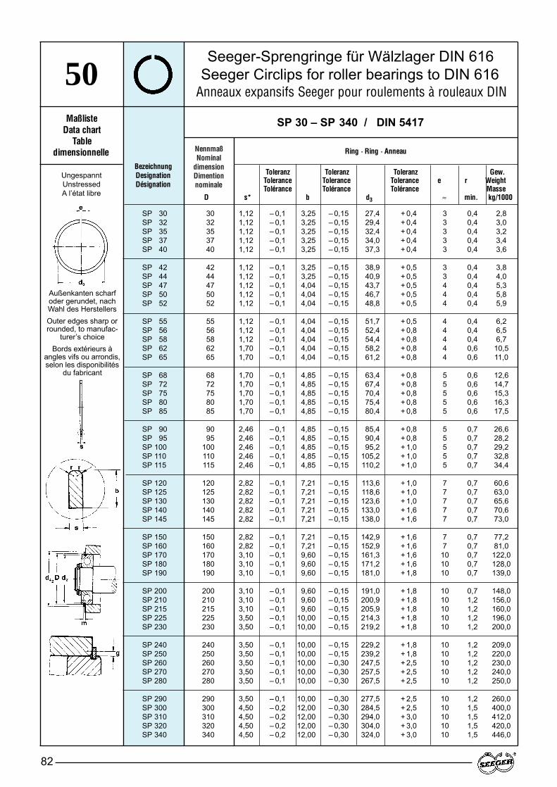
NennmaßNominal
dimensionDimention nominale
Seeger-Sprengringe für Wälzlager DIN 616Seeger Circlips for roller bearings to DIN 616
Anneaux expansifs Seeger pour roulements à rouleaux DIN
82
50Maßliste
Data chartTable
dimensionnelle
Toleranz Toleranz Toleranz Gew.Tolerance Tolerance Tolerance e r WeightTolérance Tolérance Tolérance Masse
D s* b d3 ≈ min. kg/1000
BezeichnungDesignationDésignation
SP 30 – SP 340 / DIN 5417
Ring · Ring · Anneau
Außenkanten scharfoder gerundet, nachWahl des HerstellersOuter edges sharp orrounded, to manufac-
turer’s choiceBords extérieurs à
angles vifs ou arrondis,selon les disponibilités
du fabricant
UngespanntUnstressedA l’état libre
SP 30 30 1,12 – 0,1 3,25 – 0,15 27,4 + 0,4 3 0,4 2,8SP 32 32 1,12 – 0,1 3,25 – 0,15 29,4 + 0,4 3 0,4 3,0SP 35 35 1,12 – 0,1 3,25 – 0,15 32,4 + 0,4 3 0,4 3,2SP 37 37 1,12 – 0,1 3,25 – 0,15 34,0 + 0,4 3 0,4 3,4SP 40 40 1,12 – 0,1 3,25 – 0,15 37,3 + 0,4 3 0,4 3,6
SP 42 42 1,12 – 0,1 3,25 – 0,15 38,9 + 0,5 3 0,4 3,8SP 44 44 1,12 – 0,1 3,25 – 0,15 40,9 + 0,5 3 0,4 4,0SP 47 47 1,12 – 0,1 4,04 – 0,15 43,7 + 0,5 4 0,4 5,3SP 50 50 1,12 – 0,1 4,04 – 0,15 46,7 + 0,5 4 0,4 5,8SP 52 52 1,12 – 0,1 4,04 – 0,15 48,8 + 0,5 4 0,4 5,9
SP 55 55 1,12 – 0,1 4,04 – 0,15 51,7 + 0,5 4 0,4 6,2SP 56 56 1,12 – 0,1 4,04 – 0,15 52,4 + 0,8 4 0,4 6,5SP 58 58 1,12 – 0,1 4,04 – 0,15 54,4 + 0,8 4 0,4 6,7SP 62 62 1,70 – 0,1 4,04 – 0,15 58,2 + 0,8 4 0,6 10,5SP 65 65 1,70 – 0,1 4,04 – 0,15 61,2 + 0,8 4 0,6 11,0
SP 68 68 1,70 – 0,1 4,85 – 0,15 63,4 + 0,8 5 0,6 12,6SP 72 72 1,70 – 0,1 4,85 – 0,15 67,4 + 0,8 5 0,6 14,7SP 75 75 1,70 – 0,1 4,85 – 0,15 70,4 + 0,8 5 0,6 15,3SP 80 80 1,70 – 0,1 4,85 – 0,15 75,4 + 0,8 5 0,6 16,3SP 85 85 1,70 – 0,1 4,85 – 0,15 80,4 + 0,8 5 0,6 17,5
SP 90 90 2,46 – 0,1 4,85 – 0,15 85,4 + 0,8 5 0,7 26,6SP 95 95 2,46 – 0,1 4,85 – 0,15 90,4 + 0,8 5 0,7 28,2SP 100 100 2,46 – 0,1 4,85 – 0,15 95,2 + 1,0 5 0,7 29,2SP 110 110 2,46 – 0,1 4,85 – 0,15 105,2 + 1,0 5 0,7 32,8SP 115 115 2,46 – 0,1 4,85 – 0,15 110,2 + 1,0 5 0,7 34,4
SP 120 120 2,82 – 0,1 7,21 – 0,15 113,6 + 1,0 7 0,7 60,6SP 125 125 2,82 – 0,1 7,21 – 0,15 118,6 + 1,0 7 0,7 63,0SP 130 130 2,82 – 0,1 7,21 – 0,15 123,6 + 1,0 7 0,7 65,6SP 140 140 2,82 – 0,1 7,21 – 0,15 133,0 + 1,6 7 0,7 70,6SP 145 145 2,82 – 0,1 7,21 – 0,15 138,0 + 1,6 7 0,7 73,0
SP 150 150 2,82 – 0,1 7,21 – 0,15 142,9 + 1,6 7 0,7 77,2SP 160 160 2,82 – 0,1 7,21 – 0,15 152,9 + 1,6 7 0,7 81,0SP 170 170 3,10 – 0,1 9,60 – 0,15 161,3 + 1,6 10 0,7 122,0SP 180 180 3,10 – 0,1 9,60 – 0,15 171,2 + 1,6 10 0,7 128,0SP 190 190 3,10 – 0,1 9,60 – 0,15 181,0 + 1,8 10 0,7 139,0
SP 200 200 3,10 – 0,1 9,60 – 0,15 191,0 + 1,8 10 0,7 148,0SP 210 210 3,10 – 0,1 9,60 – 0,15 200,9 + 1,8 10 1,2 156,0SP 215 215 3,10 – 0,1 9,60 – 0,15 205,9 + 1,8 10 1,2 160,0SP 225 225 3,50 – 0,1 10,00 – 0,15 214,3 + 1,8 10 1,2 196,0SP 230 230 3,50 – 0,1 10,00 – 0,15 219,2 + 1,8 10 1,2 200,0
SP 240 240 3,50 – 0,1 10,00 – 0,15 229,2 + 1,8 10 1,2 209,0SP 250 250 3,50 – 0,1 10,00 – 0,15 239,2 + 1,8 10 1,2 220,0SP 260 260 3,50 – 0,1 10,00 – 0,30 247,5 + 2,5 10 1,2 230,0SP 270 270 3,50 – 0,1 10,00 – 0,30 257,5 + 2,5 10 1,2 240,0SP 280 280 3,50 – 0,1 10,00 – 0,30 267,5 + 2,5 10 1,2 250,0
SP 290 290 3,50 – 0,1 10,00 – 0,30 277,5 + 2,5 10 1,2 260,0SP 300 300 4,50 – 0,2 12,00 – 0,30 284,5 + 2,5 10 1,5 400,0SP 310 310 4,50 – 0,2 12,00 – 0,30 294,0 + 3,0 10 1,5 412,0SP 320 320 4,50 – 0,2 12,00 – 0,30 304,0 + 3,0 10 1,5 420,0SP 340 340 4,50 – 0,2 12,00 – 0,30 324,0 + 3,0 10 1,5 446,0
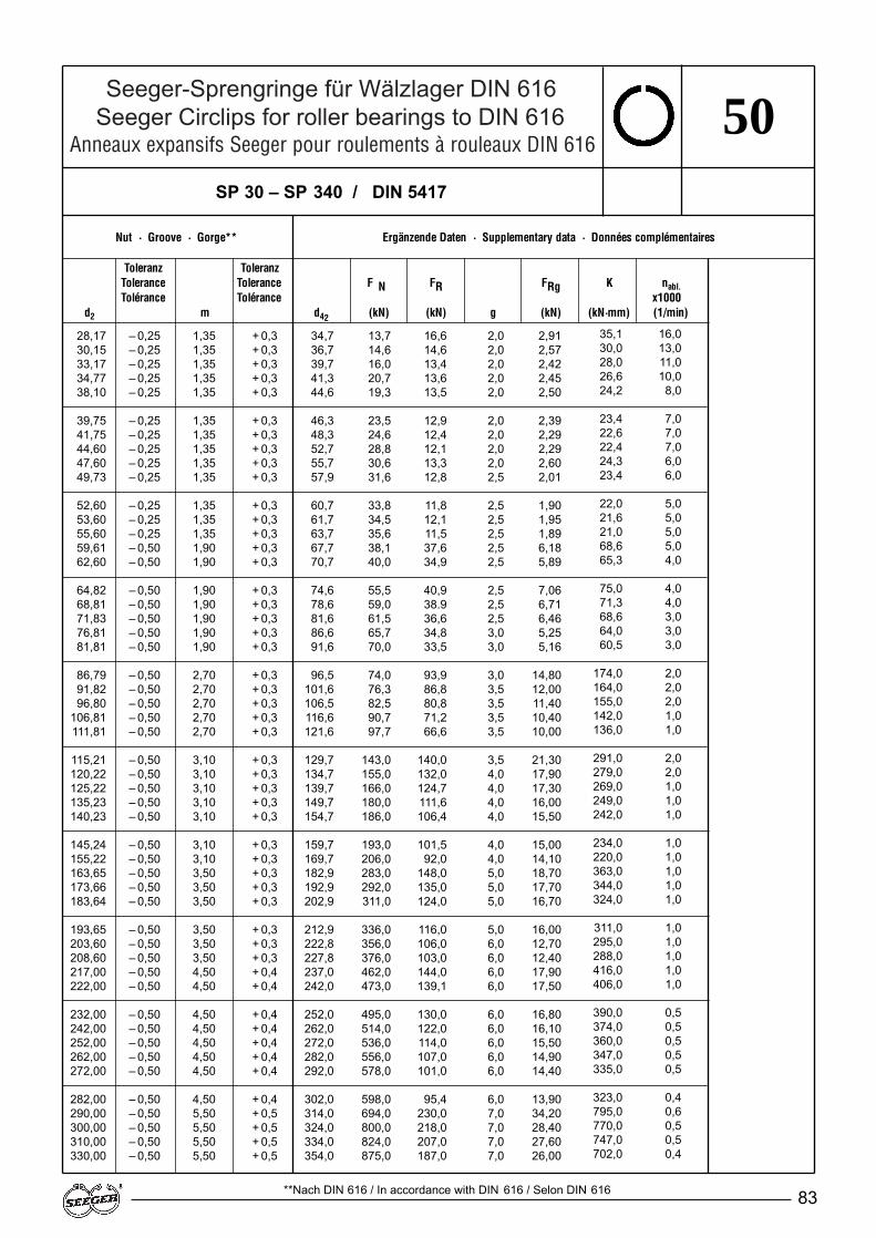
Seeger-Sprengringe für Wälzlager DIN 616Seeger Circlips for roller bearings to DIN 616
Anneaux expansifs Seeger pour roulements à rouleaux DIN 616
83
50
Nut · Groove · Gorge** Ergänzende Daten · Supplementary data · Données complémentaires
Toleranz ToleranzTolerance Tolerance F N FR FRg K nabl.Tolérance Tolérance x1000
d2 m d42 (kN) (kN) g (kN) (kN·mm) (1/min)
**Nach DIN 616 / In accordance with DIN 616 / Selon DIN 616
SP 30 – SP 340 / DIN 5417
35,1 16,030,0 13,028,0 11,026,6 10,024,2 8,0
23,4 7,022,6 7,022,4 7,024,3 6,023,4 6,0
22,0 5,021,6 5,021,0 5,068,6 5,065,3 4,0
75,0 4,071,3 4,068,6 3,064,0 3,060,5 3,0
174,0 2,0164,0 2,0155,0 2,0142,0 1,0136,0 1,0
291,0 2,0279,0 2,0269,0 1,0249,0 1,0242,0 1,0
234,0 1,0220,0 1,0363,0 1,0344,0 1,0324,0 1,0
311,0 1,0295,0 1,0288,0 1,0416,0 1,0406,0 1,0
390,0 0,5374,0 0,5360,0 0,5347,0 0,5335,0 0,5
323,0 0,4795,0 0,6770,0 0,5747,0 0,5702,0 0,4
28,17 – 0,25 1,35 + 0,3 34,7 13,7 16,6 2,0 2,9130,15 – 0,25 1,35 + 0,3 36,7 14,6 14,6 2,0 2,5733,17 – 0,25 1,35 + 0,3 39,7 16,0 13,4 2,0 2,4234,77 – 0,25 1,35 + 0,3 41,3 20,7 13,6 2,0 2,4538,10 – 0,25 1,35 + 0,3 44,6 19,3 13,5 2,0 2,50
39,75 – 0,25 1,35 + 0,3 46,3 23,5 12,9 2,0 2,3941,75 – 0,25 1,35 + 0,3 48,3 24,6 12,4 2,0 2,2944,60 – 0,25 1,35 + 0,3 52,7 28,8 12,1 2,0 2,2947,60 – 0,25 1,35 + 0,3 55,7 30,6 13,3 2,0 2,6049,73 – 0,25 1,35 + 0,3 57,9 31,6 12,8 2,5 2,01
52,60 – 0,25 1,35 + 0,3 60,7 33,8 11,8 2,5 1,9053,60 – 0,25 1,35 + 0,3 61,7 34,5 12,1 2,5 1,9555,60 – 0,25 1,35 + 0,3 63,7 35,6 11,5 2,5 1,8959,61 – 0,50 1,90 + 0,3 67,7 38,1 37,6 2,5 6,1862,60 – 0,50 1,90 + 0,3 70,7 40,0 34,9 2,5 5,89
64,82 – 0,50 1,90 + 0,3 74,6 55,5 40,9 2,5 7,0668,81 – 0,50 1,90 + 0,3 78,6 59,0 38.9 2,5 6,7171,83 – 0,50 1,90 + 0,3 81,6 61,5 36,6 2,5 6,4676,81 – 0,50 1,90 + 0,3 86,6 65,7 34,8 3,0 5,2581,81 – 0,50 1,90 + 0,3 91,6 70,0 33,5 3,0 5,16
86,79 – 0,50 2,70 + 0,3 96,5 74,0 93,9 3,0 14,8091,82 – 0,50 2,70 + 0,3 101,6 76,3 86,8 3,5 12,0096,80 – 0,50 2,70 + 0,3 106,5 82,5 80,8 3,5 11,40
106,81 – 0,50 2,70 + 0,3 116,6 90,7 71,2 3,5 10,40111,81 – 0,50 2,70 + 0,3 121,6 97,7 66,6 3,5 10,00
115,21 – 0,50 3,10 + 0,3 129,7 143,0 140,0 3,5 21,30120,22 – 0,50 3,10 + 0,3 134,7 155,0 132,0 4,0 17,90125,22 – 0,50 3,10 + 0,3 139,7 166,0 124,7 4,0 17,30135,23 – 0,50 3,10 + 0,3 149,7 180,0 111,6 4,0 16,00140,23 – 0,50 3,10 + 0,3 154,7 186,0 106,4 4,0 15,50
145,24 – 0,50 3,10 + 0,3 159,7 193,0 101,5 4,0 15,00155,22 – 0,50 3,10 + 0,3 169,7 206,0 92,0 4,0 14,10163,65 – 0,50 3,50 + 0,3 182,9 283,0 148,0 5,0 18,70173,66 – 0,50 3,50 + 0,3 192,9 292,0 135,0 5,0 17,70183,64 – 0,50 3,50 + 0,3 202,9 311,0 124,0 5,0 16,70
193,65 – 0,50 3,50 + 0,3 212,9 336,0 116,0 5,0 16,00203,60 – 0,50 3,50 + 0,3 222,8 356,0 106,0 6,0 12,70208,60 – 0,50 3,50 + 0,3 227,8 376,0 103,0 6,0 12,40217,00 – 0,50 4,50 + 0,4 237,0 462,0 144,0 6,0 17,90222,00 – 0,50 4,50 + 0,4 242,0 473,0 139,1 6,0 17,50
232,00 – 0,50 4,50 + 0,4 252,0 495,0 130,0 6,0 16,80242,00 – 0,50 4,50 + 0,4 262,0 514,0 122,0 6,0 16,10252,00 – 0,50 4,50 + 0,4 272,0 536,0 114,0 6,0 15,50262,00 – 0,50 4,50 + 0,4 282,0 556,0 107,0 6,0 14,90272,00 – 0,50 4,50 + 0,4 292,0 578,0 101,0 6,0 14,40
282,00 – 0,50 4,50 + 0,4 302,0 598,0 95,4 6,0 13,90290,00 – 0,50 5,50 + 0,5 314,0 694,0 230,0 7,0 34,20300,00 – 0,50 5,50 + 0,5 324,0 800,0 218,0 7,0 28,40310,00 – 0,50 5,50 + 0,5 334,0 824,0 207,0 7,0 27,60330,00 – 0,50 5,50 + 0,5 354,0 875,0 187,0 7,0 26,00
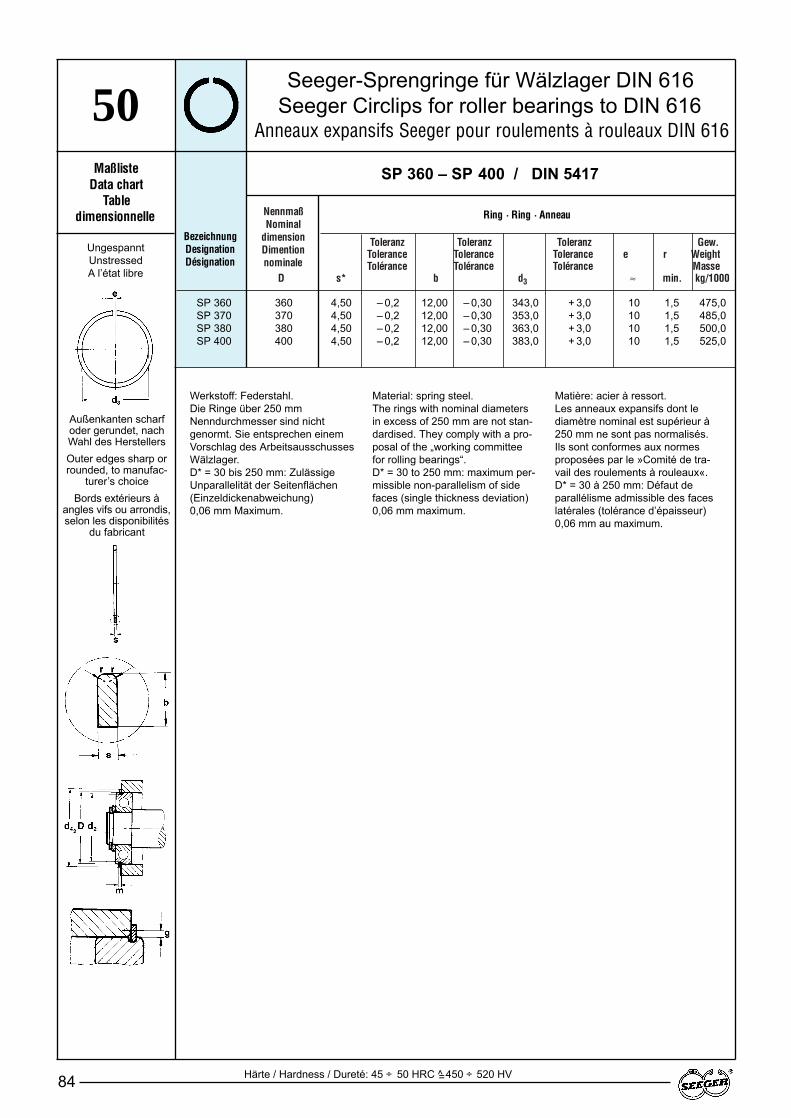
Toleranz Toleranz Toleranz Gew.Tolerance Tolerance Tolerance e r WeightTolérance Tolérance Tolérance Masse
D s* b d3 ≈ min. kg/1000
NennmaßNominal
dimensionDimention nominale
Seeger-Sprengringe für Wälzlager DIN 616Seeger Circlips for roller bearings to DIN 616
Anneaux expansifs Seeger pour roulements à rouleaux DIN 616
84
50Maßliste
Data chartTable
dimensionnelleBezeichnungDesignationDésignation
SP 360 – SP 400 / DIN 5417
Ring · Ring · Anneau
Außenkanten scharfoder gerundet, nachWahl des HerstellersOuter edges sharp orrounded, to manufac-
turer’s choiceBords extérieurs à
angles vifs ou arrondis,selon les disponibilités
du fabricant
UngespanntUnstressedA l’état libre
Werkstoff: Federstahl.Die Ringe über 250 mmNenndurchmesser sind nichtgenormt. Sie entsprechen einemVorschlag des ArbeitsausschussesWälzlager.D* = 30 bis 250 mm: ZulässigeUnparallelität der Seitenflächen(Einzeldickenabweichung) 0,06 mm Maximum.
Material: spring steel.The rings with nominal diametersin excess of 250 mm are not stan-dardised. They comply with a pro-posal of the „working committeefor rolling bearings“.D* = 30 to 250 mm: maximum per-missible non-parallelism of sidefaces (single thickness deviation)0,06 mm maximum.
Matière: acier à ressort.Les anneaux expansifs dont lediamètre nominal est supérieur à250 mm ne sont pas normalisés.Ils sont conformes aux normesproposées par le »Comité de tra-vail des roulements à rouleaux«.D* = 30 à 250 mm: Défaut deparallélisme admissible des faceslatérales (tolérance d’épaisseur)0,06 mm au maximum.
Härte / Hardness / Dureté: 45 ÷ 50 HRC ^ 450 ÷ 520 HV=
SP 360 360 4,50 – 0,2 12,00 – 0,30 343,0 + 3,0 10 1,5 475,0SP 370 370 4,50 – 0,2 12,00 – 0,30 353,0 + 3,0 10 1,5 485,0SP 380 380 4,50 – 0,2 12,00 – 0,30 363,0 + 3,0 10 1,5 500,0SP 400 400 4,50 – 0,2 12,00 – 0,30 383,0 + 3,0 10 1,5 525,0
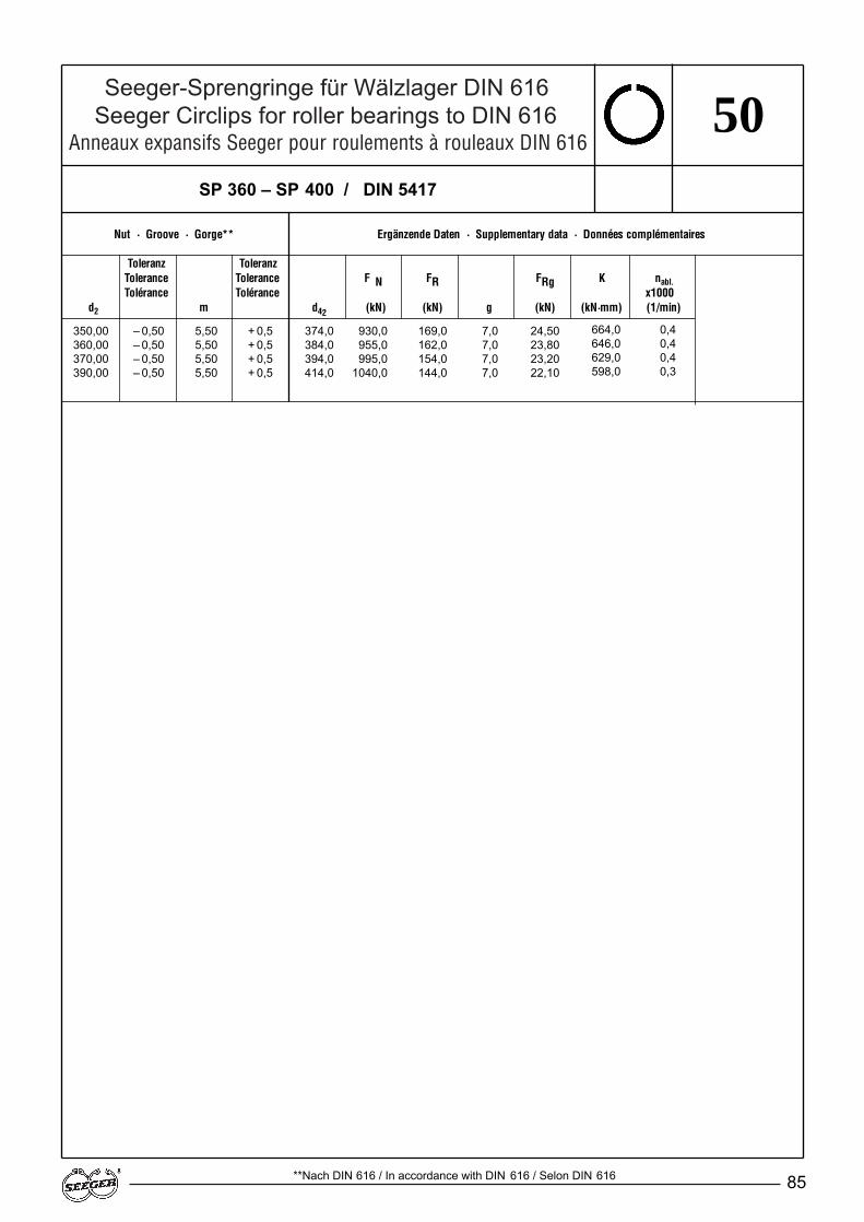
Seeger-Sprengringe für Wälzlager DIN 616Seeger Circlips for roller bearings to DIN 616
Anneaux expansifs Seeger pour roulements à rouleaux DIN 616
85
50
Nut · Groove · Gorge** Ergänzende Daten · Supplementary data · Données complémentaires
Toleranz ToleranzTolerance Tolerance F N FR FRg K nabl.Tolérance Tolérance x1000
d2 m d42 (kN) (kN) g (kN) (kN·mm) (1/min)
SP 360 – SP 400 / DIN 5417
664,0 0,4646,0 0,4629,0 0,4598,0 0,3
**Nach DIN 616 / In accordance with DIN 616 / Selon DIN 616
350,00 – 0,50 5,50 + 0,5 374,0 930,0 169,0 7,0 24,50360,00 – 0,50 5,50 + 0,5 384,0 955,0 162,0 7,0 23,80370,00 – 0,50 5,50 + 0,5 394,0 995,0 154,0 7,0 23,20390,00 – 0,50 5,50 + 0,5 414,0 1040,0 144,0 7,0 22,10
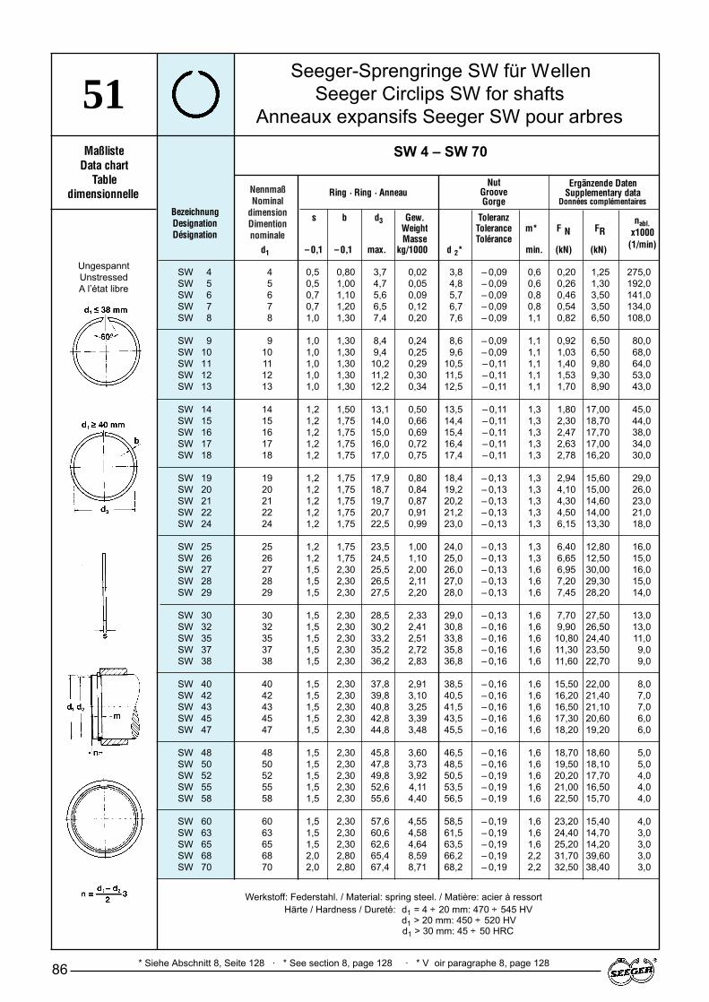
NennmaßNominal
dimensionDimention nominale
Seeger-Sprengringe SW für WellenSeeger Circlips SW for shafts
Anneaux expansifs Seeger SW pour arbres
86
51Maßliste
Data chartTable
dimensionnelle
s b d3 Gew. ToleranzWeight Tolerance m* F N FRMasse Tolérance
d1 – 0,1 – 0,1 max. kg/1000 d 2* min. (kN) (kN)
BezeichnungDesignationDésignation
* Siehe Abschnitt 8, Seite 128 · * See section 8, page 128 · * V oir paragraphe 8, page 128
SW 4 – SW 70
Ring · Ring · Anneau
SW 4 4 0,5 0,80 3,7 0,02 3,8 – 0,09 0,6 0,20 1,25 275,0SW 5 5 0,5 1,00 4,7 0,05 4,8 – 0,09 0,6 0,26 1,30 192,0SW 6 6 0,7 1,10 5,6 0,09 5,7 – 0,09 0,8 0,46 3,50 141,0SW 7 7 0,7 1,20 6,5 0,12 6,7 – 0,09 0,8 0,54 3,50 134,0SW 8 8 1,0 1,30 7,4 0,20 7,6 – 0,09 1,1 0,82 6,50 108,0
SW 9 9 1,0 1,30 8,4 0,24 8,6 – 0,09 1,1 0,92 6,50 80,0SW 10 10 1,0 1,30 9,4 0,25 9,6 – 0,09 1,1 1,03 6,50 68,0SW 11 11 1,0 1,30 10,2 0,29 10,5 – 0,11 1,1 1,40 9,80 64,0SW 12 12 1,0 1,30 11,2 0,30 11,5 – 0,11 1,1 1,53 9,30 53,0SW 13 13 1,0 1,30 12,2 0,34 12,5 – 0,11 1,1 1,70 8,90 43,0
SW 14 14 1,2 1,50 13,1 0,50 13,5 – 0,11 1,3 1,80 17,00 45,0SW 15 15 1,2 1,75 14,0 0,66 14,4 – 0,11 1,3 2,30 18,70 44,0SW 16 16 1,2 1,75 15,0 0,69 15,4 – 0,11 1,3 2,47 17,70 38,0SW 17 17 1,2 1,75 16,0 0,72 16,4 – 0,11 1,3 2,63 17,00 34,0SW 18 18 1,2 1,75 17,0 0,75 17,4 – 0,11 1,3 2,78 16,20 30,0
SW 19 19 1,2 1,75 17,9 0,80 18,4 – 0,13 1,3 2,94 15,60 29,0SW 20 20 1,2 1,75 18,7 0,84 19,2 – 0,13 1,3 4,10 15,00 26,0SW 21 21 1,2 1,75 19,7 0,87 20,2 – 0,13 1,3 4,30 14,60 23,0SW 22 22 1,2 1,75 20,7 0,91 21,2 – 0,13 1,3 4,50 14,00 21,0SW 24 24 1,2 1,75 22,5 0,99 23,0 – 0,13 1,3 6,15 13,30 18,0
SW 25 25 1,2 1,75 23,5 1,00 24,0 – 0,13 1,3 6,40 12,80 16,0SW 26 26 1,2 1,75 24,5 1,10 25,0 – 0,13 1,3 6,65 12,50 15,0SW 27 27 1,5 2,30 25,5 2,00 26,0 – 0,13 1,6 6,95 30,00 16,0SW 28 28 1,5 2,30 26,5 2,11 27,0 – 0,13 1,6 7,20 29,30 15,0SW 29 29 1,5 2,30 27,5 2,20 28,0 – 0,13 1,6 7,45 28,20 14,0
SW 30 30 1,5 2,30 28,5 2,33 29,0 – 0,13 1,6 7,70 27,50 13,0SW 32 32 1,5 2,30 30,2 2,41 30,8 – 0,16 1,6 9,90 26,50 13,0SW 35 35 1,5 2,30 33,2 2,51 33,8 – 0,16 1,6 10,80 24,40 11,0SW 37 37 1,5 2,30 35,2 2,72 35,8 – 0,16 1,6 11,30 23,50 9,0SW 38 38 1,5 2,30 36,2 2,83 36,8 – 0,16 1,6 11,60 22,70 9,0
SW 40 40 1,5 2,30 37,8 2,91 38,5 – 0,16 1,6 15,50 22,00 8,0SW 42 42 1,5 2,30 39,8 3,10 40,5 – 0,16 1,6 16,20 21,40 7,0SW 43 43 1,5 2,30 40,8 3,25 41,5 – 0,16 1,6 16,50 21,10 7,0SW 45 45 1,5 2,30 42,8 3,39 43,5 – 0,16 1,6 17,30 20,60 6,0SW 47 47 1,5 2,30 44,8 3,48 45,5 – 0,16 1,6 18,20 19,20 6,0
SW 48 48 1,5 2,30 45,8 3,60 46,5 – 0,16 1,6 18,70 18,60 5,0SW 50 50 1,5 2,30 47,8 3,73 48,5 – 0,16 1,6 19,50 18,10 5,0SW 52 52 1,5 2,30 49,8 3,92 50,5 – 0,19 1,6 20,20 17,70 4,0SW 55 55 1,5 2,30 52,6 4,11 53,5 – 0,19 1,6 21,00 16,50 4,0SW 58 58 1,5 2,30 55,6 4,40 56,5 – 0,19 1,6 22,50 15,70 4,0
SW 60 60 1,5 2,30 57,6 4,55 58,5 – 0,19 1,6 23,20 15,40 4,0SW 63 63 1,5 2,30 60,6 4,58 61,5 – 0,19 1,6 24,40 14,70 3,0SW 65 65 1,5 2,30 62,6 4,64 63,5 – 0,19 1,6 25,20 14,20 3,0SW 68 68 2,0 2,80 65,4 8,59 66,2 – 0,19 2,2 31,70 39,60 3,0SW 70 70 2,0 2,80 67,4 8,71 68,2 – 0,19 2,2 32,50 38,40 3,0
UngespanntUnstressedA l’état libre
nabl.x1000
(1/min)
Härte / Hardness / Dureté: d1 = 4 ÷ 20 mm: 470 ÷ 545 HVHärte / Hardeness / d1 > 20 mm: 450 ÷ 520 HV
d1 > 30 mm: 45 ÷ 50 HRC
Werkstoff: Federstahl. / Material: spring steel. / Matière: acier à ressort
Nut GrooveGorge
Ergänzende DatenSupplementary data
Données complémentaires

Seeger-Sprengringe SW für WellenSeeger Circlips SW for shafts
Anneaux expansifs Seeger SW pour arbres51Maßliste
Data chartTable
dimensionnelleBezeichnungDesignationDésignation
SW 72 – SW 340
UngespanntUnstressedA l’état libre
nabl.x1000
(1/min)
87* Siehe Abschnitt 8, Seite 128 · * See section 8, page 128 · * V oir paragraphe 8, page 128
SW 72 72 2,0 2,80 69,4 8,80 70,2 – 0,19 2,2 33,70 37,60 3,0SW 73 73 2,0 2,80 70,4 8,90 71,2 – 0,19 2,2 34,00 37,00 3,0SW 75 75 2,0 2,80 72,4 9,32 73,2 – 0,19 2,2 35,00 36,20 2,0SW 80 80 2,0 2,80 77,4 9,67 78,2 – 0,19 2,2 37,40 34,20 2,0SW 85 85 2,5 3,40 82,0 16,00 83,0 – 0,22 2,7 44,00 72,00 2,0
SW 90 90 2,5 3,40 87,0 16,00 88,0 – 0,22 2,7 46,50 66,30 2,0SW 95 95 2,5 3,40 92,0 18,20 93,0 – 0,22 2,7 49,20 61,80 2,0SW 100 100 2,5 3,40 97,0 18,90 98,0 – 0,22 2,7 51,90 57,30 2,0SW 105 105 2,5 3,40 101,7 20,70 102,7 – 0,22 2,7 65,00 54,00 2,0SW 110 110 2,5 3,40 106,6 20,90 107,7 – 0,22 2,7 69,00 50,40 1,0
SW 115 115 2,5 3,40 111,6 22,10 112,7 – 0,22 2,7 71,00 47,20 1,0SW 120 120 2,5 3,40 116,5 24,10 117,7 – 0,22 2,7 75,00 44,80 1,0SW 125 125 2,5 3,40 121,5 25,10 122,7 – 0,25 2,7 78,50 41,80 1,0SW 130 130 2,5 3,40 126,4 26,60 127,7 – 0,25 2,7 84,00 39,60 1,0SW 135 135 2,5 4,00 131,1 30,20 132,4 – 0,25 2,7 87,00 44,00 1,0
SW 140 140 2,5 4,00 136,0 31,10 137,4 – 0,25 2,7 91,50 41,60 1,0SW 145 145 2,5 4,00 141,0 32,60 142,4 – 0,25 2,7 95,00 39,60 1,0SW 150 150 2,5 4,00 145,9 32,80 147,4 – 0,25 2,7 98,00 37,50 1,0SW 155 155 2,5 4,00 150,9 34,70 154,4 – 0,25 2,7 100,00 36,30 1,0SW 160 160 2,5 4,00 155,8 36,60 157,4 – 0,25 2,7 103,00 35,60 1,0
SW 165 165 2,5 4,00 160,8 37,40 162,4 – 0,25 2,7 106,00 34,20 0,5SW 170 170 2,5 4,00 165,7 38,50 167,4 – 0,25 2,7 108,00 33,50 0,5SW 175 175 2,5 4,00 170,7 39,40 172,4 – 0,25 2,7 117,00 32,20 0,4SW 180 180 3,0 5,00 175,2 61,20 177,0 – 0,25 3,2 140,00 67,50 1,0SW 185 185 3,0 5,00 180,2 63,90 182,0 – 0,29 3,2 144,00 66,20 1,0
SW 190 190 3,0 5,00 185,1 65,90 187,0 – 0,29 3,2 148,00 64,00 1,0SW 195 195 3,0 5,00 190,1 67,50 192,0 – 0,29 3,2 152,00 62,60 1,0SW 200 200 3,0 5,00 196,0 68,40 197,0 – 0,29 3,2 156,00 61,40 0,5SW 210 210 3,0 5,00 204,9 72,00 207,0 – 0,29 3,2 164,00 58,00 0,5SW 220 220 3,0 5,00 214,8 76,30 217,0 – 0,29 3,2 171,00 55,50 0,4
SW 230 230 3,0 5,00 224,7 79,80 227,0 – 0,29 3,2 180,00 53,00 0,3SW 240 240 3,0 5,00 234,6 81,70 237,0 – 0,29 3,2 187,00 51,00 0,3SW 250 250 3,0 5,00 244,5 86,50 247,0 – 0,32 3,2 195,00 49,00 0,3SW 260 260 4,0 7,50 252,4 179,00 255,0 – 0,32 4,2 338,00 168,00 0,4SW 265 265 4,0 7,50 257,4 185,20 260,0 – 0,32 4,2 344,00 165,00 0,4
SW 270 270 4,0 7,50 262,3 197,70 265,0 – 0,32 4,2 350,00 162,00 0,4SW 280 280 4,0 7,50 272,2 198,70 275,0 – 0,32 4,2 362,00 155,00 0,4SW 285 285 4,0 7,50 277,2 199,50 280,0 – 0,32 4,2 370,00 151,00 0,3SW 290 290 4,0 7,50 282,1 205,30 285,0 – 0,32 4,2 377,00 148,00 0,3SW 300 300 4,0 7,50 292,1 214,20 295,0 – 0,32 4,2 390,00 145,00 0,3
SW 305 305 4,0 7,50 297,1 219,40 300,0 – 0,32 4,2 396,00 142,00 0,3SW 310 310 4,0 7,50 302,0 223,10 305,0 – 0,32 4,2 402,00 139,00 0,3SW 320 320 4,0 7,50 311,9 225,30 315,0 – 0,32 4,2 416,00 137,00 0,3SW 330 330 4,0 7,50 321,8 228,60 325,0 – 0,36 4,2 428,00 132,00 0,2SW 340 340 4,0 7,50 331,7 239,30 335,0 – 0,36 4,2 442,00 129,00 0,2
Härte / Hardness / Dureté: d1 = 4 ÷ 20 mm: 470 ÷ 545 HVHärte / Hardeness / d1 > 20 mm: 450 ÷ 520 HV
d1 > 30 mm: 45 ÷ 50 HRC
Werkstoff: Federstahl. / Material: spring steel. / Matière: acier à ressort
NennmaßNominal
dimensionDimention nominale
s b d3 Gew. ToleranzWeight Tolerance m* F N FRMasse Tolérance
d1 – 0,1 – 0,1 max. kg/1000 d 2* min. (kN) (kN)
Ring · Ring · AnneauNut
GrooveGorge
Ergänzende DatenSupplementary data
Données complémentaires

Nut GrooveGorge
Ergänzende DatenSupplementary data
Données complémentaires
* Siehe Abschnitt 8, Seite 128 · * See section 8, page 128 · * V oir paragraphe 8, page 128
SW 350 350 4,0 7,50 341,6 251,20 345,0 – 0,36 4,2 455,00 123,00 0,2SW 360 360 4,0 7,50 351,5 253,10 355,0 – 0,36 4,2 468,00 120,00 0,2SW 370 370 4,0 7,50 361,5 259,20 365,0 – 0,36 4,2 482,00 117,00 0,2SW 380 380 4,0 7,50 371,4 265,80 375,0 – 0,36 4,2 494,00 115,00 0,2SW 390 390 4,0 7,50 381,3 273,90 385,0 – 0,36 4,2 507,00 112,00 0,2
SW 400 400 4,0 7,50 391,2 281,10 395,0 – 0,36 4,2 521,00 109,00 0,1SW 420 420 4,5 12,00 410,0 531,00 415,0 – 0,36 4,8 547,00 133,00 0,3SW 460 460 4,5 12,00 449,5 582,00 455,0 – 0,36 4,8 600,00 126,00 0,2
Seeger-Sprengringe SW für WellenSeeger Circlips SW for shafts
Anneaux expansifs Seeger SW pour arbres51Maßliste
Data chartTable
dimensionnelle NennmaßNominal
dimensionDimension nominale
BezeichnungDesignationDésignation
SW 350 – SW 460
Ring · Ring · Anneau
UngespanntUnstressedA l’état libre
nabl.x1000
(1/min)
Härte / Hardness / Dureté: d1 = 4 ÷ 20 mm: 47 ÷ 52 HRC ^ 470 ÷ 545 HVHärte / Hardeness / d1 > 20 mm: 45 ÷ 50 HRC ^ 450 ÷ 520 HV
==
Werkstoff: Federstahl. / Material: spring steel. / Matière: acier à ressort
88
s b d3 Gew. ToleranzWeight Tolerance m* F N FRMasse Tolérance
d1 – 0,1 – 0,1 max. kg/1000 d 2* min. (kN) (kN)

Seeger-Sprengringe SB für BohrungenSeeger Circlips SB for bores
Anneaux expansifs Seeger SB pour alésages
89
52
NennmaßNominal
dimensionDimension nominale
s b d3 Gew. ToleranzWeight Tolerance m* F N FRMasse Tolérance
d1 – 0,1 – 0,1 min. kg/1000 d 2* min. (kN) (kN)
BezeichnungDesignationDésignation
SB 7 – SB 57
Ring · Ring · Anneau
SB 7 7 0,8 1,00 7,5 0,09 7,3 + 0,09 0,9 0,55 3,30SB 8 8 0,8 1,00 8,5 0,10 8,3 + 0,09 0,9 0,65 3,25SB 9 9 0,8 1,10 9,5 0,13 9,3 + 0,09 0,9 0,70 3,20SB 10 10 0,8 1,20 10,6 0,15 10,4 + 0,09 0,9 1,05 3,15SB 11 11 1,0 1,30 11,6 0,21 11,4 + 0,11 1,1 1,15 9,15
SB 12 12 1,0 1,30 12,7 0,25 12,4 + 0,11 1,1 1,30 8,90SB 13 13 1,0 1,30 13,8 0,28 13,5 + 0,11 1,1 1,75 8,80SB 14 14 1,0 1,30 14,8 0,31 14,5 + 0,11 1,1 1,90 8,20SB 15 15 1,0 1,30 15,8 0,34 15,5 + 0,11 1,1 2,00 7,70SB 16 16 1,2 1,75 16,8 0,53 16,5 + 0,11 1,3 2,10 15,50
SB 17 17 1,2 1,75 17,8 0,55 17,5 + 0,11 1,3 2,25 15,40SB 18 18 1,2 1,75 18,9 0,68 18,5 + 0,13 1,3 2,40 15,10SB 19 19 1,2 1,75 19,9 0,72 19,6 + 0,13 1,3 3,00 14,80SB 20 20 1,2 1,75 21,0 0,76 20,6 + 0,13 1,3 3,20 14,20SB 21 21 1,2 1,75 22,0 0,79 21,6 + 0,13 1,3 3,35 13,70
SB 22 22 1,2 1,75 23,0 0,81 22,6 + 0,13 1,3 3,50 13,10SB 23 23 1,2 1,75 24,0 0,88 23,6 + 0,13 1,3 3,65 12,80SB 24 24 1,2 1,75 25,2 0,90 24,8 + 0,13 1,3 5,10 12,50SB 25 25 1,2 1,75 26,2 0,91 25,8 + 0,13 1,3 5,30 12,00SB 26 26 1,2 1,75 27,2 0,98 26,8 + 0,13 1,3 5,50 11,50
SB 27 27 1,2 1,75 28,2 1,11 27,8 + 0,13 1,3 5,70 11,30SB 28 28 1,2 1,75 29,2 1,13 28,8 + 0,13 1,3 5,95 11,00SB 29 29 1,2 1,75 30,2 1,15 29,8 + 0,13 1,3 6,15 10,90SB 30 30 1,5 2,30 31,4 2,00 31,0 + 0,16 1,6 8,00 26,00SB 31 31 1,5 2,30 32,4 2,03 32,0 + 0,16 1,6 8,25 25,60
SB 32 32 1,5 2,30 33,4 2,11 33,0 + 0,16 1,6 8,50 25,00SB 33 33 1,5 2,30 34,4 2,26 34,0 + 0,16 1,6 8,75 24,60SB 34 34 1,5 2,30 35,4 2,34 35,0 + 0,16 1,6 9,00 23,80SB 35 35 1,5 2,30 36,4 2,36 36,0 + 0,16 1,6 9,30 23,30SB 37 37 1,5 2,30 38,8 2,53 38,2 + 0,16 1,6 11,75 22,00
SB 38 38 1,5 2,30 39,8 2,61 39,2 + 0,16 1,6 12,15 21,60SB 39 39 1,5 2,30 40,8 2,67 40,2 + 0,16 1,6 12,40 21,00SB 40 40 1,5 2,30 41,8 2,80 41,2 + 0,16 1,6 12,70 20,70SB 42 42 1,5 2,30 43,8 2,92 43,2 + 0,16 1,6 13,30 19,80SB 43 43 1,5 2,30 44,8 3,03 44,2 + 0,16 1,6 13,70 19,60
SB 44 44 1,5 2,30 45,8 3,11 45,2 + 0,16 1,6 14,00 19,30SB 45 45 1,5 2,30 46,8 3,25 46,2 + 0,16 1,6 14,25 19,00SB 46 46 1,5 2,30 47,8 3,28 47,2 + 0,16 1,6 14,65 18,40SB 47 47 1,5 2,30 48,8 3,29 48,2 + 0,16 1,6 14,90 18,10SB 48 48 1,5 2,30 49,8 3,45 49,2 + 0,16 1,6 15,30 17,60
SB 50 50 1,5 2,30 51,8 3,57 51,2 + 0,19 1,6 15,80 17,20SB 52 52 1,5 2,30 54,3 3,58 53,5 + 0,19 1,6 20,65 16,30SB 53 53 1,5 2,30 55,3 3,82 54,5 + 0,19 1,6 21,05 16,10SB 55 55 1,5 2,30 57,3 3,93 56,5 + 0,19 1,6 21,80 15,70SB 57 57 1,5 2,30 59,3 4,12 58,5 + 0,19 1,6 22,60 15,30
Nut · Groove · GorgeTragfähigkeit
Load bearing capacityCapacité de charge
* Siehe Abschnitt 8, Seite 128 · * See section 8, page 128 · * V oir paragraphe 8, page 128
UngespanntUnstressedA l’état libre
Härte / Hardness / Dureté: d1 = 4 ÷ 20 mm: 470 ÷ 545 HVHärte / Hardeness / d1 > 20 mm: 450 ÷ 520 HV
d1 > 30 mm: 45 ÷ 50 HRC
MaßlisteData chart
Tabledimensionnelle

NennmaßNominal
dimensionDimention nominale
Seeger-Sprengringe SB für BohrungenSeeger Circlips SB for bores
Anneaux expansifs Seeger SB pour alésages
90
52Maßliste
Data chartTable
dimensionnelleBezeichnungDesignationDésignation
SB 58 – SB 153
Ring · Ring · Anneau
SB 58 58 1,5 2,30 60,3 4,13 59,5 + 0,19 1,6 23,00 15,00SB 60 60 1,5 2,30 62,3 4,28 61,5 + 0,19 1,6 23,80 14,60SB 62 62 1,5 2,30 64,3 4,42 63,5 + 0,19 1,6 24,60 14,20SB 63 63 1,5 2,30 65,3 4,50 64,5 + 0,19 1,6 25,00 13,70SB 65 65 1,5 2,30 67,3 4,72 66,5 + 0,19 1,6 25,70 13,60
SB 68 68 1,5 2,30 70,3 4,90 69,5 + 0,19 1,6 26,90 12,90SB 70 70 1,5 2,30 72,3 4,93 71,5 + 0,19 1,6 27,70 12,80SB 72 72 2,0 2,80 74,6 8,49 73,8 + 0,19 2,2 34,20 35,70SB 73 73 2,0 2,80 75,6 8,52 74,8 + 0,19 2,2 34,70 35,30SB 74 74 2,0 2,80 76,6 8,60 75,8 + 0,19 2,2 35,30 34,80
SB 76 76 2,0 2,80 78,6 8,89 77,8 + 0,19 2,2 36,20 33,80SB 78 78 2,0 2,80 80,6 9,05 79,8 + 0,19 2,2 37,10 32,60SB 79 79 2,0 2,80 81,6 9,07 80,8 + 0,22 2,2 37,60 32,00SB 80 80 2,0 2,80 82,6 9,22 81,8 + 0,22 2,2 38,00 31,40SB 81 81 2,0 2,80 83,6 9,31 82,8 + 0,22 2,2 38,60 31,30
SB 82 82 2,0 2,80 84,6 9,45 83,8 + 0,22 2,2 39,00 30,70SB 83 83 2,0 2,80 85,6 9,63 84,8 + 0,22 2,2 39,50 30,10SB 85 85 2,0 2,80 87,6 9,81 86,8 + 0,22 2,2 40,40 29,60SB 86 86 2,0 2,80 88,6 9,91 87,8 + 0,22 2,2 40,90 29,00SB 88 88 2,5 3,40 91,0 15,40 90,0 + 0,22 2,7 46,50 65,80
SB 90 90 2,5 3,40 93,0 15,60 92,0 + 0,22 2,7 47,60 63,50SB 92 92 2,5 3,40 95,0 16,60 94,0 + 0,22 2,7 48,60 62,00SB 93 93 2,5 3,40 96,0 16,80 95,0 + 0,22 2,7 49,20 61,80SB 95 95 2,5 3,40 98,0 16,90 97,0 + 0,22 2,7 50,20 59,30SB 97 97 2,5 3,40 100,0 17,10 99,0 + 0,22 2,7 51,30 58,20
SB 98 98 2,5 3,40 101,0 17,50 100,0 + 0,22 2,7 51,80 56,60SB 100 100 2,5 3,40 103,0 17,90 102,0 + 0,22 2,7 52,80 55,50SB 102 102 2,5 3,40 105,3 18,40 104,3 + 0,22 2,7 62,00 53,60SB 103 103 2,5 3,40 106,3 18,50 105,3 + 0,22 2,7 62,60 53,20SB 105 105 2,5 3,40 108,3 18,70 107,3 + 0,22 2,7 63,80 51,80
SB 107 107 2,5 3,40 110,3 19,10 109,3 + 0,22 2,7 65,00 50,70SB 108 108 2,5 3,40 111,3 19,30 110,3 + 0,22 2,7 65,60 50,50SB 110 110 2,5 3,40 113,4 19,80 112,3 + 0,22 2,7 66,80 49,00SB 112 112 2,5 3,40 115,4 20,30 114,3 + 0,22 2,7 68,00 47,00SB 113 113 2,5 3,40 116,4 20,50 115,3 + 0,22 2,7 68,60 46,50
SB 115 115 2,5 3,40 118,4 20,60 117,3 + 0,22 2,7 69,40 45,50SB 117 117 2,5 3,40 120,4 20,80 119,3 + 0,22 2,7 71,00 44,60SB 118 118 2,5 3,40 121,4 21,10 120,3 + 0,25 2,7 71,70 44,20SB 120 120 2,5 3,40 123,5 21,40 122,3 + 0,25 2,7 72,80 43,30SB 123 123 2,5 3,40 126,5 22,00 125,3 + 0,25 2,7 74,70 41,20
SB 125 125 2,5 3,40 128,5 22,50 127,3 + 0,25 2,7 75,90 40,20SB 127 127 2,5 3,40 130,5 23,00 129,3 + 0,25 2,7 77,00 39,80SB 130 130 2,5 3,40 133,6 23,40 132,3 + 0,25 2,7 78,90 38,20SB 133 133 2,5 3,40 136,6 24,40 135,3 + 0,25 2,7 80,70 36,80SB 135 135 2,5 3,40 138,6 25,00 137,3 + 0,25 2,7 81,90 36,60
SB 137 137 2,5 3,40 140,6 25,30 139,3 + 0,25 2,7 83,00 35,60SB 140 140 2,5 4,00 144,0 29,30 142,6 + 0,25 2,7 96,10 40,20SB 143 143 2,5 4,00 147,0 30,10 145,6 + 0,25 2,7 98,10 38,60SB 150 150 2,5 4,00 154,1 31,90 152,6 + 0,25 2,7 102,00 36,20SB 153 153 2,5 4,00 157,1 32,60 155,6 + 0,25 2,7 104,00 35,60
Nut · Groove · GorgeTragfähigkeit
Load bearing capacityCapacité de charge
* Siehe Abschnitt 8, Seite 128 · * See section 8, page 128 · * V oir paragraphe 8, page 128
s b d3 Gew. ToleranzWeight Tolerance m* F N FRMasse Tolérance
d1 – 0,1 – 0,1 min. kg/1000 d 2* min. (kN) (kN)
UngespanntUnstressedA l’état libre

91* Siehe Abschnitt 8, Seite 128 · * See section 8, page 128 · * V oir paragraphe 8, page 128
Nut · Groove · GorgeTragfähigkeit
Load bearing capacityCapacité de charge
Seeger-Sprengringe SB für BohrungenSeeger Circlips SB for bores
Anneaux expansifs Seeger SB pour alésages52
BezeichnungDesignationDésignation
SB 160 – SB 440
SB 160 160 2,5 4,00 164,2 34,40 162,6 + 0,25 2,7 108,00 34,60SB 163 163 2,5 4,00 167,2 34,60 165,6 + 0,25 2,7 111,00 33,50SB 165 165 2,5 4,00 169,2 34,90 167,6 + 0,25 2,7 113,00 32,80SB 170 170 2,5 4,00 174,3 36,20 172,6 + 0,25 2,7 116,00 32,00SB 173 173 2,5 4,00 177,3 37,10 175,6 + 0,25 2,7 118,00 32,00
SB 175 175 2,5 4,00 179,3 37,30 177,6 + 0,25 2,7 119,00 31,40SB 180 180 2,5 4,00 184,5 38,30 182,6 + 0,29 2,7 123,00 30,80SB 183 183 2,5 4,00 187,5 41,00 185,6 + 0,29 2,7 125,00 30,00SB 190 190 3,0 5,00 194,9 61,30 193,0 + 0,29 3,2 150,00 62,80SB 195 195 3,0 5,00 199,9 61,60 198,0 + 0,29 3,2 154,00 61,50
SB 200 200 3,0 5,00 205,0 64,50 203,0 + 0,29 3,2 158,00 59,00SB 205 205 3,0 5,00 210,0 66,40 208,0 + 0,29 3,2 162,00 57,80SB 210 210 3,0 5,00 215,1 68,80 213,0 + 0,29 3,2 166,00 56,80SB 215 215 3,0 5,00 220,1 69,50 218,0 + 0,29 3,2 169,00 55,50SB 220 220 3,0 5,00 225,2 72,40 223,0 + 0,29 3,2 173,00 54,40
SB 225 225 3,0 5,00 230,2 72,90 228,0 + 0,29 3,2 177,00 53,30SB 230 230 3,0 5,00 235,3 75,20 233,0 + 0,29 3,2 181,00 52,00SB 240 240 3,0 5,00 245,4 80,90 243,0 + 0,29 3,2 189,00 49,60SB 250 250 3,0 5,00 255,5 84,20 253,0 + 0,32 3,2 197,00 48,50SB 260 260 4,0 7,50 267,6 165,00 265,0 + 0,32 4,2 343,00 162,00
SB 270 270 4,0 7,50 277,7 174,00 275,0 + 0,32 4,2 356,00 157,00SB 280 280 4,0 7,50 287,8 184,00 285,0 + 0,32 4,2 369,00 152,00SB 290 290 4,0 7,50 297,9 190,00 295,0 + 0,32 4,2 382,00 144,00SB 300 300 4,0 7,50 307,9 196,00 305,0 + 0,32 4,2 395,00 140,00SB 310 310 4,0 7,50 318,0 200,00 315,0 + 0,32 4,2 408,00 136,00
SB 320 320 4,0 7,50 328,1 203,00 325,0 + 0,36 4,2 422,00 132,00SB 325 325 4,0 7,50 333,1 206,00 330,0 + 0,36 4,2 428,00 129,00SB 330 330 4,0 7,50 338,2 209,00 335,0 + 0,36 4,2 435,00 126,00SB 340 340 4,0 7,50 348,3 219,00 345,0 + 0,36 4,2 448,00 123,00SB 350 350 4,0 7,50 358,4 229,00 355,0 + 0,36 4,2 452,00 121,00
SB 355 355 4,0 7,50 363,4 231,00 360,0 + 0,36 4,2 467,00 121,00SB 360 360 4,0 7,50 368,5 233,00 365,0 + 0,36 4,2 487,00 119,00SB 370 370 4,0 7,50 378,5 236,00 375,0 + 0,36 4,2 493,00 116,00SB 375 375 4,0 7,50 383,5 240,00 380,0 + 0,36 4,2 500,00 112,00SB 380 380 4,0 7,50 388,6 242,00 385,0 + 0,36 4,2 513,00 111,00
SB 390 390 4,0 7,50 398,7 253,00 395,0 + 0,36 4,2 520,00 110,00SB 395 395 4,0 7,50 403,7 257,00 400,0 + 0,36 4,2 526,00 109,00SB 400 400 4,0 7,50 408,9 260,00 405,0 + 0,40 4,2 529,00 106,00SB 410 410 4,0 7,50 419,0 266,00 415,0 + 0,40 4,2 546,00 105,00SB 420 415 4,0 7,50 424,0 273,00 420,0 + 0,40 4,2 552,00 104,00
SB 420 420 4,0 7,50 429,1 277,00 425,0 + 0,40 4,2 553,00 101,00SB 430 430 4,0 7,50 439,2 285,00 435,0 + 0,40 4,2 565,00 100,00SB 440 440 4,0 7,50 449,3 294,00 445,0 + 0,40 4,2 578,00 98,00
NennmaßNominal
dimensionDimention nominale
Ring · Ring · Anneau
s b d3 Gew. ToleranzWeight Tolerance m* F N FRMasse Tolérance
d1 – 0,1 – 0,1 min. kg/1000 d 2* min. (kN) (kN)
UngespanntUnstressedA l’état libre
Härte / Hardness / Dureté: d1 = 4 ÷ 20 mm: 470 ÷ 545 HVHärte / Hardeness / d1 > 20 mm: 450 ÷ 520 HV
d1 > 30 mm: 45 ÷ 50 HRC
MaßlisteData chart
Tabledimensionnelle
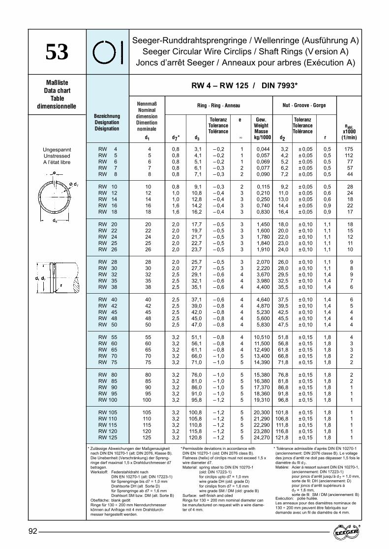
NennmaßNominal
dimensionDimention nominale
Seeger-Runddrahtsprengringe / Wellenringe (Ausführung A)Seeger Circular Wire Circlips / Shaft Rings (V ersion A)
Joncs d’arrêt Seeger / Anneaux pour arbres (Exécution A)
92
53Maßliste
Data chartTable
dimensionnelle
Toleranz e Gew. ToleranzTolerance Weight ToleranceTolérance Masse Tolérance
d1 d7* d3 ≈ kg/1000 d2 r
BezeichnungDesignationDésignation
RW 4 – RW 125 / DIN 7993*
Ring · Ring · Anneau
RW 4 4 0,8 3,1 – 0,2 1 0,044 3,2 ± 0,05 0,5 175RW 5 5 0,8 4,1 – 0,2 1 0,057 4,2 ± 0,05 0,5 112RW 6 6 0,8 5,1 – 0,2 1 0,069 5,2 ± 0,05 0,5 77RW 7 7 0,8 6,1 – 0,3 2 0,077 6,2 ± 0,05 0,5 57RW 8 8 0,8 7,1 – 0,3 2 0,090 7,2 ± 0,05 0,5 44
RW 10 10 0,8 9,1 – 0,3 2 0,115 9,2 ± 0,05 0,5 28RW 12 12 1,0 10,8 – 0,4 3 0,210 11,0 ± 0,05 0,6 24RW 14 14 1,0 12,8 – 0,4 3 0,250 13,0 ± 0,05 0,6 18RW 16 16 1,6 14,2 – 0,4 3 0,740 14,4 ± 0,05 0,9 22RW 18 18 1,6 16,2 – 0,4 3 0,830 16,4 ± 0,05 0,9 17
RW 20 20 2,0 17,7 – 0,5 3 1,450 18,0 ± 0,10 1,1 18RW 22 22 2,0 19,7 – 0,5 3 1,600 20,0 ± 0,10 1,1 15RW 24 24 2,0 21,7 – 0,5 3 1,780 22,0 ± 0,10 1,1 12RW 25 25 2,0 22,7 – 0,5 3 1,840 23,0 ± 0,10 1,1 11RW 26 26 2,0 23,7 – 0,5 3 1,910 24,0 ± 0,10 1,1 10
RW 28 28 2,0 25,7 – 0,5 3 2,070 26,0 ± 0,10 1,1 9RW 30 30 2,0 27,7 – 0,5 3 2,220 28,0 ± 0,10 1,1 8RW 32 32 2,5 29,1 – 0,6 4 3,670 29,5 ± 0,10 1,4 9RW 35 35 2,5 32,1 – 0,6 4 3,980 32,5 ± 0,10 1,4 7RW 38 38 2,5 35,1 – 0,6 4 4,400 35,5 ± 0,10 1,4 6
RW 40 40 2,5 37,1 – 0,6 4 4,640 37,5 ± 0,10 1,4 6RW 42 42 2,5 39,0 – 0,8 4 4,870 39,5 ± 0,10 1,4 5RW 45 45 2,5 42,0 – 0,8 4 5,230 42,5 ± 0,10 1,4 4RW 48 48 2,5 45,0 – 0,8 4 5,600 45,5 ± 0,10 1,4 4RW 50 50 2,5 47,0 – 0,8 4 5,830 47,5 ± 0,10 1,4 4
RW 55 55 3,2 51,1 – 0,8 4 10,510 51,8 ± 0,15 1,8 4RW 60 60 3,2 56,1 – 0,8 4 11,500 56,8 ± 0,15 1,8 3RW 65 65 3,2 61,1 – 0,8 4 12,490 61,8 ± 0,15 1,8 3RW 70 70 3,2 66,0 – 1,0 5 13,400 66,8 ± 0,15 1,8 2RW 75 75 3,2 71,0 – 1,0 5 14,390 71,8 ± 0,15 1,8 2
RW 80 80 3,2 76,0 – 1,0 5 15,380 76,8 ± 0,15 1,8 2RW 85 85 3,2 81,0 – 1,0 5 16,380 81,8 ± 0,15 1,8 2RW 90 90 3,2 86,0 – 1,0 5 17,370 86,8 ± 0,15 1,8 1RW 95 95 3,2 91,0 – 1,0 5 18,360 91,8 ± 0,15 1,8 1RW 100 100 3,2 95,8 – 1,2 5 19,310 96,8 ± 0,15 1,8 1
RW 105 105 3,2 100,8 – 1,2 5 20,300 101,8 ± 0,15 1,8 1RW 110 110 3,2 105,8 – 1,2 5 21,290 106,8 ± 0,15 1,8 1RW 115 115 3,2 110,8 – 1,2 5 22,290 111,8 ± 0,15 1,8 1RW 120 120 3,2 115,8 – 1,2 5 23,280 116,8 ± 0,15 1,8 1RW 125 125 3,2 120,8 – 1,2 5 24,270 121,8 ± 0,15 1,8 1
Nut · Groove · Gorge
* Zulässige Abweichungen der Maßgenauigkeit nach DIN EN 10270-1 (alt: DIN 2076, Klasse B).Die Unebenheit (Verschränkung) der Spreng-ringe darf maximal 1,5 x Drahtdurchmesser d7betragen.Werkstoff: Federstahldraht nach
DIN EN 10270-1 (alt: DIN 17223-1) für Sprengringe bis d7 = 1,0 mmDrahtsorte DH (alt Sorte D)für Sprengringe ab d7 = 1,6 mm Drahtsort SM bzw. DM (alt: Sorte B)
Obefläche: blank geöltRinge für 130 ÷ 200 mm Nenndurchmesserkönnen auf Anfrage mit 4 mm Drahtdurch-messer hergestellt werden.
*Permissible deviations in accordance with DIN EN 10270-1 (old: DIN 2076 class B).Flatness (helix) of circlips must not exceed 1,5 xwire diameter d7.Material: spring steel to DIN EN 10270-1
(old: DIN 17223-1)for circlips upto d7 = 1,0 mm wire grade DH (old: grade D)for cirslips from d7 = 1,6 mm wire grade SM / DM (old: grade B)
Surface: self-finish and oiledRings for 130 ÷ 200 mm nominal diameter canbe manufactured on request with a wire diame-ter of 4 mm.
* Tolérance admissible d’après DIN EN 10270-1(anciennement: DIN 2076 classe B). Le voilagedes joncs d’arrêt ne doit pas dépasser 1,5 fois lediamètre du fil d7.Matière: Acier à ressort suivant DIN EN 10270-1,
(anciennement: DIN 17223-1)pour joncs d’arrêt jusqu’à d7 = 1,0 mm,sorte de fil: DH (anciennement: D)pour joncs d’arrêt supérieurs à d7 = 1,6 mm, sorte de fil: SM / DM (anciennement: B)
Exécution: polie huilée.Les anneaux pour des diamètres nominaux de 130 ÷ 200 mm peuvent être fabriqués sur demande avec un fil de diamètre de 4 mm.
UngespanntUnstressedA l’état libre
nabl.x1000
(1/min)
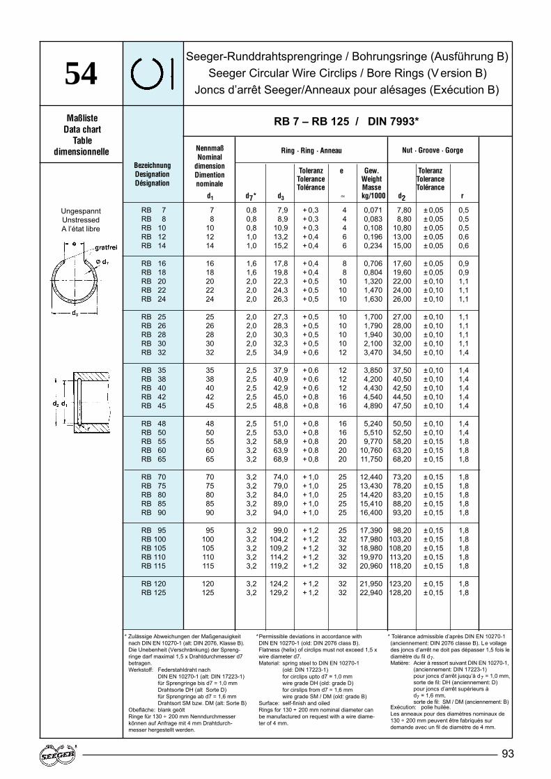
93
NennmaßNominal
dimensionDimention nominale
Toleranz e Gew. ToleranzTolerance Weight ToleranceTolérance Masse Tolérance
d1 d7* d3 ≈ kg/1000 d2 r
Ring · Ring · Anneau Nut · Groove · Gorge
Seeger-Runddrahtsprengringe / Bohrungsringe (Ausführung B)Seeger Circular Wire Circlips / Bore Rings (V ersion B)
Joncs d’arrêt Seeger/Anneaux pour alésages (Exécution B)54
BezeichnungDesignationDésignation
RB 7 – RB 125 / DIN 7993*
RB 7 7 0,8 7,9 + 0,3 4 0,071 7,80 ± 0,05 0,5RB 8 8 0,8 8,9 + 0,3 4 0,083 8,80 ± 0,05 0,5RB 10 10 0,8 10,9 + 0,3 4 0,108 10,80 ± 0,05 0,5RB 12 12 1,0 13,2 + 0,4 6 0,196 13,00 ± 0,05 0,6RB 14 14 1,0 15,2 + 0,4 6 0,234 15,00 ± 0,05 0,6
RB 16 16 1,6 17,8 + 0,4 8 0,706 17,60 ± 0,05 0,9RB 18 18 1,6 19,8 + 0,4 8 0,804 19,60 ± 0,05 0,9RB 20 20 2,0 22,3 + 0,5 10 1,320 22,00 ± 0,10 1,1RB 22 22 2,0 24,3 + 0,5 10 1,470 24,00 ± 0,10 1,1RB 24 24 2,0 26,3 + 0,5 10 1,630 26,00 ± 0,10 1,1
RB 25 25 2,0 27,3 + 0,5 10 1,700 27,00 ± 0,10 1,1RB 26 26 2,0 28,3 + 0,5 10 1,790 28,00 ± 0,10 1,1RB 28 28 2,0 30,3 + 0,5 10 1,940 30,00 ± 0,10 1,1RB 30 30 2,0 32,3 + 0,5 10 2,100 32,00 ± 0,10 1,1RB 32 32 2,5 34,9 + 0,6 12 3,470 34,50 ± 0,10 1,4
RB 35 35 2,5 37,9 + 0,6 12 3,850 37,50 ± 0,10 1,4RB 38 38 2,5 40,9 + 0,6 12 4,200 40,50 ± 0,10 1,4RB 40 40 2,5 42,9 + 0,6 12 4,430 42,50 ± 0,10 1,4RB 42 42 2,5 45,0 + 0,8 16 4,540 44,50 ± 0,10 1,4RB 45 45 2,5 48,8 + 0,8 16 4,890 47,50 ± 0,10 1,4
RB 48 48 2,5 51,0 + 0,8 16 5,240 50,50 ± 0,10 1,4RB 50 50 2,5 53,0 + 0,8 16 5,510 52,50 ± 0,10 1,4RB 55 55 3,2 58,9 + 0,8 20 9,770 58,20 ± 0,15 1,8RB 60 60 3,2 63,9 + 0,8 20 10,760 63,20 ± 0,15 1,8RB 65 65 3,2 68,9 + 0,8 20 11,750 68,20 ± 0,15 1,8
RB 70 70 3,2 74,0 + 1,0 25 12,440 73,20 ± 0,15 1,8RB 75 75 3,2 79,0 + 1,0 25 13,430 78,20 ± 0,15 1,8RB 80 80 3,2 84,0 + 1,0 25 14,420 83,20 ± 0,15 1,8RB 85 85 3,2 89,0 + 1,0 25 15,410 88,20 ± 0,15 1,8RB 90 90 3,2 94,0 + 1,0 25 16,400 93,20 ± 0,15 1,8
RB 95 95 3,2 99,0 + 1,2 25 17,390 98,20 ± 0,15 1,8RB 100 100 3,2 104,2 + 1,2 32 17,980 103,20 ± 0,15 1,8RB 105 105 3,2 109,2 + 1,2 32 18,980 108,20 ± 0,15 1,8RB 110 110 3,2 114,2 + 1,2 32 19,970 113,20 ± 0,15 1,8RB 115 115 3,2 119,2 + 1,2 32 20,960 118,20 ± 0,15 1,8
RB 120 120 3,2 124,2 + 1,2 32 21,950 123,20 ± 0,15 1,8RB 125 125 3,2 129,2 + 1,2 32 22,940 128,20 ± 0,15 1,8
* Zulässige Abweichungen der Maßgenauigkeit nach DIN EN 10270-1 (alt: DIN 2076, Klasse B).Die Unebenheit (Verschränkung) der Spreng-ringe darf maximal 1,5 x Drahtdurchmesser d7betragen.Werkstoff: Federstahldraht nach
DIN EN 10270-1 (alt: DIN 17223-1) für Sprengringe bis d7 = 1,0 mmDrahtsorte DH (alt Sorte D)für Sprengringe ab d7 = 1,6 mm Drahtsort SM bzw. DM (alt: Sorte B)
Obefläche: blank geöltRinge für 130 ÷ 200 mm Nenndurchmesserkönnen auf Anfrage mit 4 mm Drahtdurch-messer hergestellt werden.
*Permissible deviations in accordance with DIN EN 10270-1 (old: DIN 2076 class B).Flatness (helix) of circlips must not exceed 1,5 xwire diameter d7.Material: spring steel to DIN EN 10270-1
(old: DIN 17223-1)for circlips upto d7 = 1,0 mm wire grade DH (old: grade D)for cirslips from d7 = 1,6 mm wire grade SM / DM (old: grade B)
Surface: self-finish and oiledRings for 130 ÷ 200 mm nominal diameter canbe manufactured on request with a wire diame-ter of 4 mm.
* Tolérance admissible d’après DIN EN 10270-1(anciennement: DIN 2076 classe B). Le voilagedes joncs d’arrêt ne doit pas dépasser 1,5 fois lediamètre du fil d7.Matière: Acier à ressort suivant DIN EN 10270-1,
(anciennement: DIN 17223-1)pour joncs d’arrêt jusqu’à d7 = 1,0 mm,sorte de fil: DH (anciennement: D)pour joncs d’arrêt supérieurs à d7 = 1,6 mm, sorte de fil: SM / DM (anciennement: B)
Exécution: polie huilée.Les anneaux pour des diamètres nominaux de 130 ÷ 200 mm peuvent être fabriqués sur demande avec un fil de diamètre de 4 mm.
UngespanntUnstressedA l’état libre
MaßlisteData chart
Tabledimensionnelle
94
4.Gruppe 6:Scheiben DIN 988
Werkstoff:Paßscheiben: Stahl DIN EN 10139,Sorte DC 01C490 (Festigkeit min 490 N/mm2), Werkstoff Nr. 1.0330 (alt: St 2 K 50)Stützscheiben: Federstahl Härte: HRC 44–49
Ausführung: Ab 2 mm Dicke Seitenflächen geschlif-fen. Einzeldickenabweichung innerhalbder Dickentoleranz.
Oberfläche:Nach Wahl des HerstellersPaßscheiben: – blank und geöltStützscheiben: – blank und geölt
– phosphatiert u. geölt
Zur Beachtung:Die Werte in den Maßlisten für dieDicke gelten für die Scheiben in blan-ker und phosphatierter Ausführung.Wenn die Scheiben in Sonderaus-führung mit anderen Oberflächenbe-schichtungen geliefert werden, ver-größern sich diese Maße entspre-chend der Schichtdicke.
Anmerkung:Die Dickentoleranzen der Scheiben mitDicken 1.2/1.5/2.0 mm weichen vonDIN 988 ab. Die Scheiben 15 x 22 unddie Scheiben ab 100 x 125 sind nichtin DIN 988 enthalten. Das gleiche giltfür die Paßscheiben mit den Dicken0,15 und 0,25 mm.
Group 6:Washers DIN 988
Material:Shim washers: Steel DIN EN 10139,grade DC 01C490 (tensile strength min 490 N/mm 2), material No 1.0330 (old: St 2 K 50)Support washers: spring steel hardness: HRC 44–49.
Finish:From 2 mm thickness onwards, sidefaces are ground. Single thickness de-viations are within the thickness tole-rance.
Surface:To manufacturer's choiceShim washers – Self-finish and oiledSupport washers – Self-finish and oiled
– phosphated and oiled
Please note:The thickness tolerances of washerswith thickness of 1.2/1.5/2.0 mm devia-te from DIN 988. The 15 x 22 washersand the washers from 100 x 125 on-wards are not covered by DIN 988.The same applies to shim washerswith thickness of 0,15 and 0,25 mm.
Remarks:The thickness values specifed in thedata charts apply to the self-finish andphosphated washer versions. If specialversions of washers with dif ferent sur-face coatings are supplied, these di-mensions will be increassed by thecorresponding coating thickness.
Groupe 6:Rondelles DIN 988
Matière:Rondelles d’ajustage: acier DIN EN10139, sorte DC 01C490 (réstistance min 490 N/mm2), Matière No 1.0330 (anciennement: St 2 K 50) Rondelles d’appui: acier àressort dureté: HRC 44–49.
Exécution:A partir d'une épaisseur de 2 mm, fa-ces latérales rectifiées. Défaut de pa-rallélisme admissible dans la toléranced'épaisseur.
Surface:Selon les disponibilités du fabricantRondelles d'ajustage: – polie et huiléeRondelles d'appui: – polie et huilée
– phosphatée et huilée
Notice:Les tolérances d'épaisseur des rondel-les d'une épaisseur de 1.2/1.5/2.0 mmdiffèrent de la DIN 988. Les rondelles15 x 22 et les rondelles supérieures à100 x 125 ne figurent pas dans la DIN988. Cela est également valable pourles rondelles d'ajustage d'une épais-seur de 0,15 et 0,25 mm.
Remarque:Les valeurs indiquées dans les tablesdimensionnelles pour l'épaisseur 's'sont valables pour des rondelles polieset phosphatées. En cas d'exécutionspéciale avec revêtement de surface,cette dimension doit être augmentéede l'épaisseur du revêtement.
Maßliste Seite BezeichnungData Chart Page DesignationTable dim. Page Désignation
61 96 – 97 Seeger-Stützscheiben / Seeger support washers to / Rondelles d'appui Seeger DIN 988 SS...
62 98 – 108 Seeger-Paßscheiben m/ Seeger shim washers to / Rondelles d'ajustage Seeger DIN 988 PS...
MaßlistenData charts
Tables dimensionnelles

95
4.
Durchmessertoleranzen:
Pass-Scheiben in Sonderdicken Auf Anfrage können auch Pass-Scheiben in den Dicken: 1,1 / 1,3 / 1,4 / 1,6 / 1,7 / 1,8 / 1,9 / mmgeliefert werden.
AnlaufscheibenZur Verbesserung der Schmierwirkungkönnen Scheiben mit einer gleitphos-phatierten Oberfläche und mit radialverlaufenden Ölführungsnuten, zurbesseren Zuführung desSchmiermittels, versehen werden.
Distanz-ScheibenPass-Scheiben mit Dickentoleranzenvon – 0,02 oder ± 0,01 und eingeeng-ter Einzeldickenabweichung sind aufAnfrage lieferbar.
Verschleißfeste ScheibenWenn in der Konstruktion eine Pass-Scheibe mit einem hohen Verschleiß-Schutz gefordert ist und nicht durch-gehärtet werden sollen, können dieseauch tennifer oder carbonitriert behan-delt werden.
Diameter tolerances:
Shims in special thicknessesOn request shims can also be suppliedin the following thicknesses: 1,1 / 1,3 / 1,4 / 1,6 / 1,7 / 1,8 / 1,9 / mm.
Thrust washersFor better lubrication, washers can beprovided with a lubricated phosphatesurface and radial oil guide grooves forimproved lubricant supply.
Spacer washersOn request shims with thickness tole-rances of – 0.02 or ± 0.01 and restric-ted individual thickness tolerances canbe supplied.
Wear-resistant washersIf an application requires washers witha high wear resistance without beingthrough-hardened, they can be teniferor carbonitride treated.
Tolérances des diamètres:
Rondelles d’ajustage d’épaisseursparticulièresSur demande, des rondelles d’ajustagedans les épaisseurs: 1,1 / 1,3 / 1,4 / 1,6 / 1,7 / 1,8 / 1,9 / mmpeuvent aussi être livrées
Rondelles de butéePour améliorer l’effet de graissage, desrondelles peuvent être livrées avec unrevêtement en phosphate et être muniesde stries radiales permettant l’adductiondu lubrifiant.
EntretoisesRondelles d’ajustage avec tolérancesd'épaisseur de – 0,02 ou de ± 0,1 et va-riation réduite de l’épaisseur individuellepeuvent être livrées sur demande.
Rondelles résistant à l’usureSi, dans la construction, une rondelled’ajustage ayant une haute protectioncontre l’usure est exigée et que celle-cine doive par être trempée à cœur, cettedernière peut aussi être traitée par ten-nifer ou nitrocaburation.
MaßlistenData charts
Tables dimensionnelles
Nennmaßbereich: Außen ø D Innen ø dNominal diameter range: ø Outer.D ø Inner.D
Diamètre nominal: ø Extér.D ø Intér.D(ISO-Tol. d 12) (ISO-Tol. D 12)
3 bis/to/à 6 mm –0,030 +0,150–0,150 +0,030
über/more than/plus de 6 bis/to/à 10 mm –0,040 +0,190–0,190 +0,040
über/more than/plus de 10 bis/to/à 18 mm –0,050 +0,230–0,230 +0,050
über/more than/plus de 18 bis/to/à 30 mm –0,065 +0,275–0,275 +0,065
über/more than/plus de 30 bis/to/à 50 mm –0,080 +0,330–0,330 +0,080
über/more than/plus de 50 bis/to/à 80 mm –0,100 +0,400–0,400 +0,100
über/more than/plus de 80 bis/to/à 120 mm –0,120 +0,470–0,470 +0,120
über/more than/plus de 120 bis/to/à 180 mm -0,145 +0,545–0,545 +0,145
über/more than/plus de 180 bis/to/à 250 mm –0,170 +0,630–0,630 +0,170

Seeger-StützscheibenSeeger Support WashersRondelles d’appui Seeger
96
61Maßliste
Data chartTable
dimensionnelle
Gew.Toleranz Weight
d D S Tolerance MasseTolérance kg/1000
BezeichnungDesignationDésignation
SS 3 – SS 95 / DIN 988
DickeThicknessEpaisseur
SS 3 x 6 x 1,0 3 6 1,0 – 0,05 0,165SS 4 x 8 x 1,0 4 8 1,0 – 0,05 0,296SS 5 x 10 x 1,0 5 10 1,0 – 0,05 0,462SS 6 x 12 x 1,2 6 12 1,2 – 0,05 0,800SS 7 x 13 x 1,2 7 13 1,2 – 0,05 0,885
SS 8 x 14 x 1,2 8 14 1,2 – 0,05 0,980SS 9 x 15 x 1,2 9 15 1,2 – 0,05 1,070SS 10 x 16 x 1,2 10 16 1,2 – 0,05 1,150SS 11 x 17 x 1,2 11 17 1,2 – 0,05 1,233SS 12 x 18 x 1,2 12 18 1,2 – 0,05 1,330
SS 13 x 19 x 1,5 13 19 1,5 – 0,05 1,780SS 14 x 20 x 1,5 14 20 1,5 – 0,05 1,890SS 15 x 21 x 1,5 15 21 1,5 – 0,05 2,000SS 15 x 22 x 1,5 15 22 1,5 – 0,05 2,050SS 16 x 22 x 1,5 16 22 1,5 – 0,05 2,100
SS 17 x 24 x 1,5 17 24 1,5 – 0,05 2,650SS 18 x 25 x 1,5 18 25 1,5 – 0,05 2,780SS 19 x 26 x 1,5 19 26 1,5 – 0,05 2,910SS 20 x 28 x 2,0 20 28 2,0 – 0,05 4,720SS 22 x 30 x 2,0 22 30 2,0 – 0,05 5,140
SS 22 x 32 x 2,0 22 32 2,0 – 0,05 6,660SS 25 x 35 x 2,0 25 35 2,0 – 0,05 7,400SS 25 x 36 x 2,0 25 36 2,0 – 0,05 8,280SS 26 x 37 x 2,0 26 37 2,0 – 0,05 8,540SS 28 x 40 x 2,0 28 40 2,0 – 0,05 10,060
SS 30 x 42 x 2,5 30 42 2,5 – 0,05 13,400SS 32 x 45 x 2,5 32 45 2,5 – 0,05 15,500SS 35 x 45 x 2,5 35 45 2,5 – 0,05 12,300SS 36 x 45 x 2,5 36 45 2,5 – 0,05 11,300SS 37 x 47 x 2,5 37 47 2,5 – 0,05 12,900
SS 40 x 50 x 2,5 40 50 2,5 – 0,05 13,900SS 42 x 52 x 2,5 42 52 2,5 – 0,05 14,500SS 45 x 55 x 3,0 45 55 3,0 – 0,06 18,600SS 45 x 56 x 3,0 45 56 3,0 – 0,06 20,400SS 48 x 60 x 3,0 48 60 3,0 – 0,06 23,700
SS 50 x 62 x 3,0 50 62 3,0 – 0,06 24,900SS 50 x 63 x 3,0 50 63 3,0 – 0,06 27,300SS 52 x 65 x 3,0 52 65 3,0 – 0,06 28,200SS 55 x 68 x 3,0 55 68 3,0 – 0,06 29,300SS 56 x 70 x 3,0 56 70 3,0 – 0,06 32,700
SS 56 x 72 x 3,0 56 72 3,0 – 0,06 38,000SS 60 x 75 x 3,0 60 75 3,0 – 0,06 37,500SS 63 x 80 x 3,0 63 80 3,0 – 0,06 45,000SS 65 x 85 x 3,5 65 85 3,5 – 0,06 63,000SS 70 x 90 x 3,5 70 90 3,5 – 0,06 69,000
SS 75 x 95 x 3,5 75 95 3,5 – 0,06 73,200SS 80 x 100 x 3,5 80 100 3,5 – 0,06 77,800SS 85 x 105 x 3,5 85 105 3,5 – 0,06 82,000SS 90 x 110 x 3,5 90 110 3,5 – 0,06 86,500SS 95 x 115 x 3,5 95 115 3,5 – 0,06 90,700
DurchmesserDiameterDiamètre

97
Seeger-StützscheibenSeeger Support WashersRondelles d’appui Seeger
61Maßliste Standard
Data chart StandardTable Exécution
dimensionnelle standard
Gew.Toleranz Weight
d D S Tolerance MasseTolérance kg/1000
BezeichnungDesignationDésignation
SS 100 – SS 170 / DIN 988
DickeThicknessEpaisseur
DurchmesserDiameterDiamètre
SS 100 x 120 x 3,5 100 120 3,5 – 0,06 95,200SS 100 x 125 x 3,5 100 125 3,5 – 0,08 122,000SS 105 x 130 x 3,5 105 130 3,5 – 0,08 127,000SS 110 x 140 x 3,5 110 140 3,5 – 0,08 162,000SS 120 x 150 x 3,5 120 150 3,5 – 0,08 175,000
SS 130 x 160 x 3,5 130 160 3,5 – 0,08 188,000SS 140 x 170 x 3,5 140 170 3,5 – 0,08 201,000SS 150 x 180 x 3,5 150 180 3,5 – 0,08 214,000SS 160 x 190 x 3,5 160 190 3,5 – 0,08 227,000SS 170 x 200 x 3,5 170 200 3,5 – 0,08 240,000
Seeger-PassscheibenSeeger Shim Washers
Rondelles d’ajustage Seeger
98
62Maßliste
Data chartTable
dimensionnelle
BezeichnungDesignationDésignation
PS 3 – PS 10 / DIN 988
PS 3 x 6 x 0,10 3 6 0,10 – 0,03 0,016PS 3 x 6 x 0,15 3 6 0,15 – 0,04 0,024PS 3 x 6 x 0,20 3 6 0,20 – 0,04 0,032PS 3 x 6 x 0,25 3 6 0,25 – 0,04 0,040PS 3 x 6 x 0,30 3 6 0,30 – 0,05 0,050
PS 3 x 6 x 0,50 3 6 0,50 – 0,05 0,083PS 3 x 6 x 1,00 3 6 1,00 – 0,05 0,165PS 4 x 8 x 0,10 4 8 0,10 – 0,03 0,030PS 4 x 8 x 0,15 4 8 0,15 – 0,04 0,045PS 4 x 8 x 0,20 4 8 0,20 – 0,04 0,060
PS 4 x 8 x 0,25 4 8 0,25 – 0,04 0,075PS 4 x 8 x 0,30 4 8 0,30 – 0,05 0,089PS 4 x 8 x 0,50 4 8 0,50 – 0,05 0,148PS 4 x 8 x 1,00 4 8 1,00 – 0,05 0,296PS 5 x 10 x 0,10 5 10 0,10 – 0,03 0,046
PS 5 x 10 x 0,15 5 10 0,15 – 0,04 0,069PS 5 x 10 x 0,20 5 10 0,20 – 0,04 0,092PS 5 x 10 x 0,25 5 10 0,25 – 0,04 0,115PS 5 x 10 x 0,30 5 10 0,30 – 0,05 0,139PS 5 x 10 x 0,50 5 10 0,50 – 0,05 0,231
PS 5 x 10 x 1,00 5 10 1,00 – 0,05 0,462PS 6 x 12 x 0,10 6 12 0,10 – 0,03 0,067PS 6 x 12 x 0,15 6 12 0,15 – 0,04 0,101PS 6 x 12 x 0,20 6 12 0,20 – 0,04 0,134PS 6 x 12 x 0,25 6 12 0,25 – 0,04 0,168
PS 6 x 12 x 0,30 6 12 0,30 – 0,05 0,200PS 6 x 12 x 0,50 6 12 0,50 – 0,05 0,333PS 6 x 12 x 1,00 6 12 1,00 – 0,05 0,666PS 7 x 13 x 0,10 7 13 0,10 – 0,03 0,074PS 7 x 13 x 0,15 7 13 0,15 – 0,04 0,111
PS 7 x 13 x 0,20 7 13 0,20 – 0,04 0,148PS 7 x 13 x 0,25 7 13 0,25 – 0,04 0,185PS 7 x 13 x 0,30 7 13 0,30 – 0,05 0,221PS 7 x 13 x 0,50 7 13 0,50 – 0,05 0,369PS 7 x 13 x 1,00 7 13 1,00 – 0,05 0,738
PS 8 x 14 x 0,10 8 14 0,10 – 0,03 0,082PS 8 x 14 x 0,15 8 14 0,15 – 0,04 0,123PS 8 x 14 x 0,20 8 14 0,20 – 0,04 0,164PS 8 x 14 x 0,25 8 14 0,25 – 0,04 0,205PS 8 x 14 x 0,30 8 14 0,30 – 0,05 0,245
PS 8 x 14 x 0,50 8 14 0,50 – 0,05 0,408PS 8 x 14 x 1,00 8 14 1,00 – 0,05 0,815PS 9 x 15 x 0,10 9 15 0,10 – 0,03 0,089PS 9 x 15 x 0,15 9 15 0,15 – 0,04 0,134PS 9 x 15 x 0,20 9 15 0,20 – 0,04 0,178
PS 9 x 15 x 0,25 9 15 0,25 – 0,04 0,223PS 9 x 15 x 0,30 9 15 0,30 – 0,05 0,270PS 9 x 15 x 0,50 9 15 0,50 – 0,05 0,445PS 9 x 15 x 1,00 9 15 1,00 – 0,05 0,891PS 10 x 16 x 0,10 10 16 0,10 – 0,03 0,096
DickeThicknessEpaisseur
DurchmesserDiameterDiamètre
Gew.Toleranz Weight
d D s Tolerance MasseTolérance kg/1000
99
Seeger-PassscheibenSeeger Shim Washers
Rondelles d’ajustage Seeger62Maßliste
Data chartTable
dimensionnelle
BezeichnungDesignationDésignation
PS 10 – PS 15 / DIN 988
PS 10 x 16 x 0,15 10 16 0,15 – 0,04 0,144PS 10 x 16 x 0,20 10 16 0,20 – 0,04 0,192PS 10 x 16 x 0,25 10 16 0,25 – 0,04 0,240PS 10 x 16 x 0,30 10 16 0,30 – 0,05 0,290PS 10 x 16 x 0,50 10 16 0,50 – 0,05 0,481
PS 10 x 16 x 1,00 10 16 1,00 – 0,05 0,963PS 11 x 17 x 0,10 11 17 0,10 – 0,03 0,103PS 11 x 17 x 0,15 11 17 0,15 – 0,04 0,155PS 11 x 17 x 0,20 11 17 0,20 – 0,04 0,206PS 11 x 17 x 0,25 11 17 0,25 – 0,04 0,258
PS 11 x 17 x 0,30 11 17 0,30 – 0,05 0,310PS 11 x 17 x 0,50 11 17 0,50 – 0,05 0,515PS 11 x 17 x 1,00 11 17 1,00 – 0,05 1,030PS 12 x 18 x 0,10 12 18 0,10 – 0,03 0,111PS 12 x 18 x 0,15 12 18 0,15 – 0,04 0,167
PS 12 x 18 x 0,20 12 18 0,20 – 0,04 0,222PS 12 x 18 x 0,25 12 18 0,25 – 0,04 0,278PS 12 x 18 x 0,30 12 18 0,30 – 0,05 0,332PS 12 x 18 x 0,50 12 18 0,50 – 0,05 0,555PS 12 x 18 x 1,00 12 18 1,00 – 0,05 1,110
PS 13 x 19 x 0,10 13 19 0,10 – 0,03 0,119PS 13 x 19 x 0,15 13 19 0,15 – 0,04 0,179PS 13 x 19 x 0,20 13 19 0,20 – 0,04 0,237PS 13 x 19 x 0,25 13 19 0,25 – 0,04 0,296PS 13 x 19 x 0,30 13 19 0,30 – 0,05 0,357
PS 13 x 19 x 0,50 13 19 0,50 – 0,05 0,595PS 13 x 19 x 1,00 13 19 1,00 – 0,05 1,190PS 13 x 19 x 1,20 13 19 1,20 – 0,07 1,428PS 14 x 20 x 0,10 14 20 0,10 – 0,03 0,126PS 14 x 20 x 0,15 14 20 0,15 – 0,04 0,189
PS 14 x 20 x 0,20 14 20 0,20 – 0,04 0,252PS 14 x 20 x 0,25 14 20 0,25 – 0,04 0,315PS 14 x 20 x 0,30 14 20 0,30 – 0,05 0,378PS 14 x 20 x 0,50 14 20 0,50 – 0,05 0,630PS 14 x20 x 1,00 14 20 1,00 – 0,05 1,260
PS 14 x 20 x 1,20 14 20 1,20 – 0,07 1,512PS 15 x 21 x 0,10 15 21 0,10 – 0,03 0,133PS 15 x 21 x 0,15 15 21 0,15 – 0,04 0,199PS 15 x 21 x 0,20 15 21 0,20 – 0,04 0,266PS 15 x 21 x 0,25 15 21 0,25 – 0,04 0,333
PS 15 x 21 x 0,30 15 21 0,30 – 0,05 0,399PS 15 x 21 x 0,50 15 21 0,50 – 0,05 0,665PS 15 x 21 x 1,00 15 21 1,00 – 0,05 1,330PS 15 x 21 x 1,20 15 21 1,20 – 0,07 1,596PS 15 x 22 x 0,10 15 22 0,10 – 0,03 0,137
PS 15 x 22 x 0,15 15 22 0,15 – 0,04 0,205PS 15 x 22 x 0,20 15 22 0,20 – 0,04 0,274PS 15 x 22 x 0,25 15 22 0,25 – 0,04 0,342PS 15 x 22 x 0,30 15 22 0,30 – 0,05 0,410PS 15 x 22 x 0,50 15 22 0,50 – 0,05 0,683
DickeThicknessEpaisseur
DurchmesserDiameterDiamètre
Gew.Toleranz Weight
d D S Tolerance MasseTolérance kg/1000
100
Seeger-PassscheibenSeeger Shim Washers
Rondelles d’ajustage Seeger62Maßliste
Data chartTable
dimensionnelle
BezeichnungDesignationDésignation
PS 15 – PS 22 / DIN 988
PS 15 x 22 x 1,00 15 22 1,00 – 0,05 1,360PS 15 x 22 x 1,20 15 22 1,20 – 0,07 1,636PS 16 x 22 x 0,10 16 22 0,10 – 0,03 0,140PS 16 x 22 x 0,15 16 22 0,15 – 0,04 0,210PS 16 x 22 x 0,20 16 22 0,20 – 0,04 0,280
PS 16 x 22 x 0,25 16 22 0,25 – 0,04 0,350PS 16 x 22 x 0,30 16 22 0,30 – 0,05 0,420PS 16 x 22 x 0,50 16 22 0,50 – 0,05 0,700PS 16 x 22 x 1,00 16 22 1,00 – 0,05 1,400PS 16 x 22 x 1,20 16 22 1.20 – 0,07 1,680
PS 17 x 24 x 0,10 17 24 0,10 – 0,03 0,177PS 17 x 24 x 0,15 17 24 0,15 – 0,04 0,266PS 17 x 24 x 0,20 17 24 0,20 – 0,04 0,354PS 17 x 24 x 0,25 17 24 0,25 – 0,04 0,443PS 17 x 24 x 0,30 17 24 0,30 – 0,05 0,530
PS 17 x 24 x 0,50 17 24 0,50 – 0,05 0,885PS 17 x 24 x 1,00 17 24 1,00 – 0,05 1,770PS 17 x 24 x 1,20 17 24 1,20 – 0,07 2,124PS 18 x 25 x 0,10 18 25 0,10 – 0,03 0,185PS 18 x 25 x 0,15 18 25 0,15 – 0,04 0,278
PS 18 x 25 x 0,20 18 25 0,20 – 0,04 0,370PS 18 x 25 x 0,25 18 25 0,25 – 0,04 0,463PS 18 x 25 x 0,30 18 25 0,30 – 0,05 0,551PS 18 x 25 x 0,50 18 25 0,50 – 0,05 0,925PS 18 x 25 x 1,00 18 25 1,00 – 0,05 1,850
PS 18 x 25 x 1,20 18 25 1,20 – 0,07 2,220PS 19 x 26 x 0,10 19 26 0,10 – 0,03 0,194PS 19 x 26 x 0,15 19 26 0,15 – 0,04 0,291PS 19 x 26 x 0,20 19 26 0,20 – 0,04 0,388PS 19 x 26 x 0,25 19 26 0,25 – 0,04 0,485
PS 19 x 26 x 0,30 19 26 0,30 – 0,05 0,584PS 19 x 26 x 0,50 19 26 0,50 – 0,05 0,970PS 19 x 26 x 1,00 19 26 1,00 – 0,05 1,940PS 19 x 26 x 1,20 19 26 1,20 – 0,07 2,358PS 20 x 28 x 0,10 20 28 0,10 – 0,03 0,236
PS 20 x 28 x 0,15 20 28 0,15 – 0,04 0,354PS 20 x 28 x 0,20 20 28 0,20 – 0,04 0,472PS 20 x 28 x 0,25 20 28 0,25 – 0,04 0,590PS 20 x 28 x 0,30 20 28 0,30 – 0,05 0,710PS 20 x 28 x 0,50 20 28 0,50 – 0,05 1,180
PS 20 x 28 x 1,00 20 28 1,00 – 0,05 2,360PS 20 x 28 x 1,20 20 28 1,20 – 0,07 2,832PS 20 x 28 x 1,50 20 28 1,50 – 0,07 3,540PS 22 x 30 x 0,10 22 30 0,10 – 0,03 0,257PS 22 x 30 x 0,15 22 30 0,15 – 0,04 0,386
PS 22 x 30 x 0,20 22 30 0,20 – 0,04 0,514PS 22 x 30 x 0,25 22 30 0,25 – 0,04 0,643PS 22 x 30 x 0,30 22 30 0,30 – 0,05 0,770PS 22 x 30 x 0,50 22 30 0,50 – 0,05 1,280PS 22 x 30 x 1,00 22 30 1,00 – 0,05 2,570
DickeThicknessEpaisseur
DurchmesserDiameterDiamètre
Gew.Toleranz Weight
d D s Tolerance MasseTolérance kg/1000

101
Seeger-PassscheibenSeeger Shim Washers
Rondelles d’ajustage Seeger62
BezeichnungDesignationDésignation
PS 22 – PS 30 / DIN 988
PS 22 x 30 x 1,20 22 30 1,20 – 0,07 3,084PS 22 x 30 x 1,50 22 30 1,50 – 0,07 3,855PS 22 x 32 x 0,10 22 32 0,10 – 0,03 0,333PS 22 x 32 x 0,15 22 32 0,15 – 0,04 0,500PS 22 x 32 x 0,20 22 32 0,20 – 0,04 0,666
PS 22 x 32 x 0,25 22 32 0,25 – 0,04 0,833PS 22 x 32 x 0,30 22 32 0,30 – 0,05 1,000PS 22 x 32 x 0,50 22 32 0,50 – 0,05 1,660PS 22 x 32 x 1,00 22 32 1,00 – 0,05 3,330PS 22 x 32 x 1,20 22 32 1,20 – 0,07 3,996
PS 22 x 32 x 1,50 22 32 1,50 – 0,07 4,995PS 25 x 35 x 0,10 25 35 0,10 – 0,03 0,370PS 25 x 35 x 0,15 25 35 0,15 – 0,04 0,555PS 25 x 35 x 0,20 25 35 0,20 – 0,04 0,740PS 25 x 35 x 0,25 25 35 0,25 – 0,04 0,925
PS 25 x 35 x 0,30 25 35 0,30 – 0,05 1,110PS 25 x 35 x 0,50 25 35 0,50 – 0,05 1,850PS 25 x 35 x 1,00 25 35 1,00 – 0,05 3,700PS 25 x 35 x 1,20 25 35 1,20 – 0,07 4,440PS 25 x 35 x 1,50 25 35 1,50 – 0,07 5,550
PS 25 x 36 x 0,10 25 36 0,10 – 0,03 0,414PS 25 x 36 x 0,15 25 36 0,15 – 0,04 0,621PS 25 x 36 x 0,20 25 36 0,20 – 0,04 0,828PS 25 x 36 x 0,25 25 36 0,25 – 0,04 1,035PS 25 x 36 x 0,30 25 36 0,30 – 0,05 1,240
PS 25 x 36 x 0,50 25 36 0,50 – 0,05 2,070PS 25 x 36 x 1,00 25 36 1,00 – 0,05 4,140PS 25 x 36 x 1,20 25 36 1,20 – 0,07 4,968PS 25 x 36 x 1,50 25 36 1,50 – 0,07 6,210PS 26 x 37 x 0,10 26 37 0,10 – 0,03 0,427
PS 26 x 37 x 0,15 26 37 0,15 – 0,04 0,641PS 26 x 37 x 0,20 26 37 0,20 – 0,04 0,854PS 26 x 37 x 0,25 26 37 0,25 – 0,04 1,068PS 26 x 37 x 0,30 26 37 0,30 – 0,05 1,280PS 26 x 37 x 0,50 26 37 0,50 – 0,05 2,130
PS 26 x 37 x 1,00 26 37 1,00 – 0,05 4,270PS 26 x 37 x 1,20 26 37 1,20 – 0,07 5,124PS 26 x 37 x 1,50 26 37 1,50 – 0,07 6,400PS 28 x 40 x 0,10 28 40 0,10 – 0,03 0,503PS 28 x 40 x 0,15 28 40 0,15 – 0,04 0,755
PS 28 x 40 x 0,20 28 40 0,20 –0,04 1,006PS 28 x 40 x 0,25 28 40 0,25 – 0,04 1,258PS 28 x 40 x 0,30 28 40 0,30 – 0,05 1,510PS 28 x 40 x 0,50 28 40 0,50 – 0,05 2,510PS 28 x 40 x 1,00 28 40 1,00 – 0,05 5,030
PS 28 x 40 x 1,20 28 40 1,20 – 0,07 6,036PS 28 x 40 x 1,50 28 40 1,50 – 0,07 7,540PS 30 x 42 x 0,10 30 42 0,10 – 0,03 0,535PS 30 x 42 x 0,15 30 42 0,15 – 0,04 0,803PS 30 x 42 x 0,20 30 42 0,20 – 0,04 1,070
DickeThicknessEpaisseur
DurchmesserDiameterDiamètre
Gew.Toleranz Weight
d D s Tolerance MasseTolérance kg/1000
MaßlisteData chart
Tabledimensionnelle
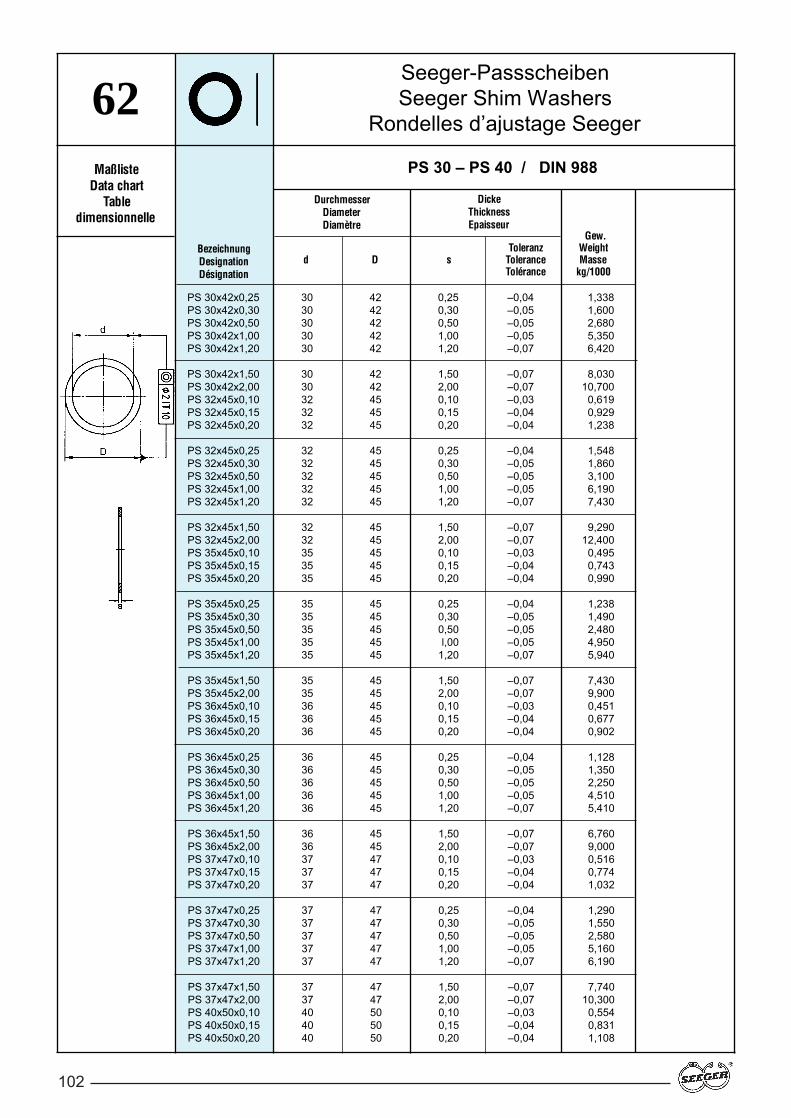
102
Seeger-PassscheibenSeeger Shim Washers
Rondelles d’ajustage Seeger62
BezeichnungDesignationDésignation
PS 30 – PS 40 / DIN 988
PS 30x42x0,25 30 42 0,25 –0,04 1,338PS 30x42x0,30 30 42 0,30 –0,05 1,600PS 30x42x0,50 30 42 0,50 –0,05 2,680PS 30x42x1,00 30 42 1,00 –0,05 5,350PS 30x42x1,20 30 42 1,20 –0,07 6,420
PS 30x42x1,50 30 42 1,50 –0,07 8,030PS 30x42x2,00 30 42 2,00 –0,07 10,700PS 32x45x0,10 32 45 0,10 –0,03 0,619PS 32x45x0,15 32 45 0,15 –0,04 0,929PS 32x45x0,20 32 45 0,20 –0,04 1,238
PS 32x45x0,25 32 45 0,25 –0,04 1,548PS 32x45x0,30 32 45 0,30 –0,05 1,860PS 32x45x0,50 32 45 0,50 –0,05 3,100PS 32x45x1,00 32 45 1,00 –0,05 6,190PS 32x45x1,20 32 45 1,20 –0,07 7,430
PS 32x45x1,50 32 45 1,50 –0,07 9,290PS 32x45x2,00 32 45 2,00 –0,07 12,400PS 35x45x0,10 35 45 0,10 –0,03 0,495PS 35x45x0,15 35 45 0,15 –0,04 0,743PS 35x45x0,20 35 45 0,20 –0,04 0,990
PS 35x45x0,25 35 45 0,25 –0,04 1,238PS 35x45x0,30 35 45 0,30 –0,05 1,490PS 35x45x0,50 35 45 0,50 –0,05 2,480PS 35x45x1,00 35 45 l,00 –0,05 4,950PS 35x45x1,20 35 45 1,20 –0,07 5,940
PS 35x45x1,50 35 45 1,50 –0,07 7,430PS 35x45x2,00 35 45 2,00 –0,07 9,900PS 36x45x0,10 36 45 0,10 –0,03 0,451PS 36x45x0,15 36 45 0,15 –0,04 0,677PS 36x45x0,20 36 45 0,20 –0,04 0,902
PS 36x45x0,25 36 45 0,25 –0,04 1,128PS 36x45x0,30 36 45 0,30 –0,05 1,350PS 36x45x0,50 36 45 0,50 –0,05 2,250PS 36x45x1,00 36 45 1,00 –0,05 4,510PS 36x45x1,20 36 45 1,20 –0,07 5,410
PS 36x45x1,50 36 45 1,50 –0,07 6,760PS 36x45x2,00 36 45 2,00 –0,07 9,000PS 37x47x0,10 37 47 0,10 –0,03 0,516PS 37x47x0,15 37 47 0,15 –0,04 0,774PS 37x47x0,20 37 47 0,20 –0,04 1,032
PS 37x47x0,25 37 47 0,25 –0,04 1,290PS 37x47x0,30 37 47 0,30 –0,05 1,550PS 37x47x0,50 37 47 0,50 –0,05 2,580PS 37x47x1,00 37 47 1,00 –0,05 5,160PS 37x47x1,20 37 47 1,20 –0,07 6,190
PS 37x47x1,50 37 47 1,50 –0,07 7,740PS 37x47x2,00 37 47 2,00 –0,07 10,300PS 40x50x0,10 40 50 0,10 –0,03 0,554PS 40x50x0,15 40 50 0,15 –0,04 0,831PS 40x50x0,20 40 50 0,20 –0,04 1,108
DickeThicknessEpaisseur
DurchmesserDiameterDiamètre
Gew.Toleranz Weight
d D s Tolerance MasseTolérance kg/1000
MaßlisteData chart
Tabledimensionnelle
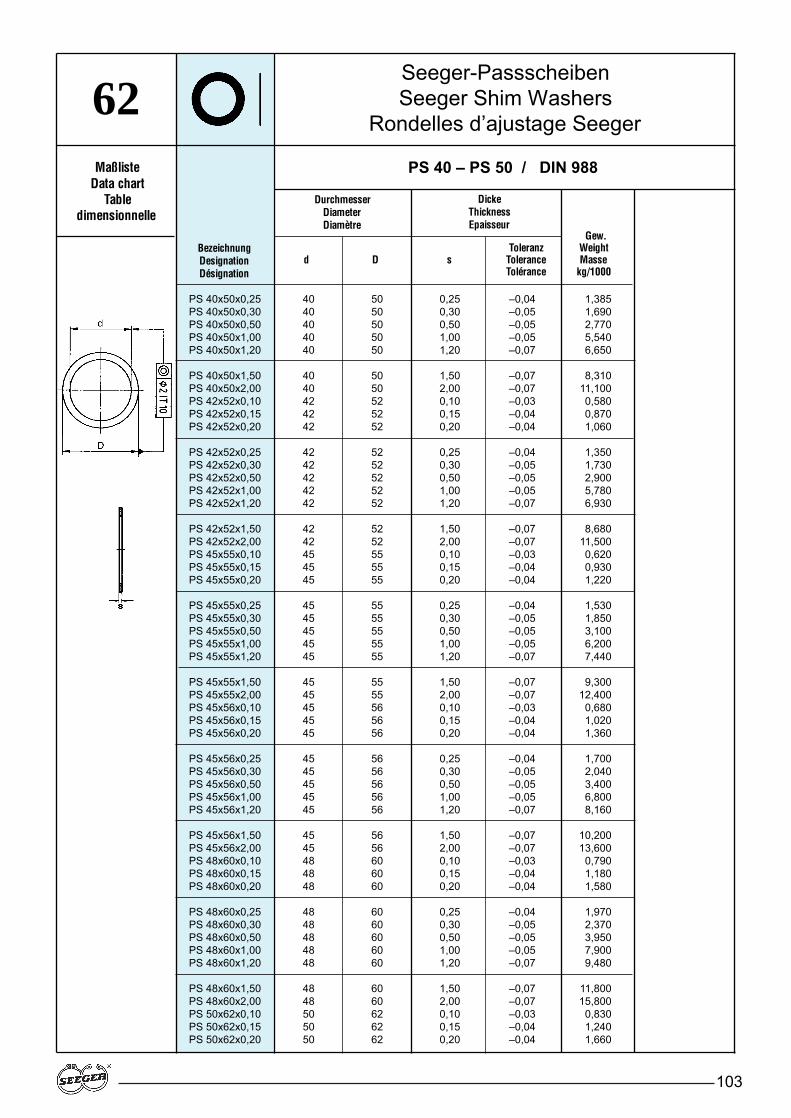
103
Seeger-PassscheibenSeeger Shim Washers
Rondelles d’ajustage Seeger62
BezeichnungDesignationDésignation
PS 40 – PS 50 / DIN 988
PS 40x50x0,25 40 50 0,25 –0,04 1,385PS 40x50x0,30 40 50 0,30 –0,05 1,690PS 40x50x0,50 40 50 0,50 –0,05 2,770PS 40x50x1,00 40 50 1,00 –0,05 5,540PS 40x50x1,20 40 50 1,20 –0,07 6,650
PS 40x50x1,50 40 50 1,50 –0,07 8,310PS 40x50x2,00 40 50 2,00 –0,07 11,100PS 42x52x0,10 42 52 0,10 –0,03 0,580PS 42x52x0,15 42 52 0,15 –0,04 0,870PS 42x52x0,20 42 52 0,20 –0,04 1,060
PS 42x52x0,25 42 52 0,25 –0,04 1,350PS 42x52x0,30 42 52 0,30 –0,05 1,730PS 42x52x0,50 42 52 0,50 –0,05 2,900PS 42x52x1,00 42 52 1,00 –0,05 5,780PS 42x52x1,20 42 52 1,20 –0,07 6,930
PS 42x52x1,50 42 52 1,50 –0,07 8,680PS 42x52x2,00 42 52 2,00 –0,07 11,500PS 45x55x0,10 45 55 0,10 –0,03 0,620PS 45x55x0,15 45 55 0,15 –0,04 0,930PS 45x55x0,20 45 55 0,20 –0,04 1,220
PS 45x55x0,25 45 55 0,25 –0,04 1,530PS 45x55x0,30 45 55 0,30 –0,05 1,850PS 45x55x0,50 45 55 0,50 –0,05 3,100PS 45x55x1,00 45 55 1,00 –0,05 6,200PS 45x55x1,20 45 55 1,20 –0,07 7,440
PS 45x55x1,50 45 55 1,50 –0,07 9,300PS 45x55x2,00 45 55 2,00 –0,07 12,400PS 45x56x0,10 45 56 0,10 –0,03 0,680PS 45x56x0,15 45 56 0,15 –0,04 1,020PS 45x56x0,20 45 56 0,20 –0,04 1,360
PS 45x56x0,25 45 56 0,25 –0,04 1,700PS 45x56x0,30 45 56 0,30 –0,05 2,040PS 45x56x0,50 45 56 0,50 –0,05 3,400PS 45x56x1,00 45 56 1,00 –0,05 6,800PS 45x56x1,20 45 56 1,20 –0,07 8,160
PS 45x56x1,50 45 56 1,50 –0,07 10,200PS 45x56x2,00 45 56 2,00 –0,07 13,600PS 48x60x0,10 48 60 0,10 –0,03 0,790PS 48x60x0,15 48 60 0,15 –0,04 1,180PS 48x60x0,20 48 60 0,20 –0,04 1,580
PS 48x60x0,25 48 60 0,25 –0,04 1,970PS 48x60x0,30 48 60 0,30 –0,05 2,370PS 48x60x0,50 48 60 0,50 –0,05 3,950PS 48x60x1,00 48 60 1,00 –0,05 7,900PS 48x60x1,20 48 60 1,20 –0,07 9,480
PS 48x60x1,50 48 60 1,50 –0,07 11,800PS 48x60x2,00 48 60 2,00 –0,07 15,800PS 50x62x0,10 50 62 0,10 –0,03 0,830PS 50x62x0,15 50 62 0,15 –0,04 1,240PS 50x62x0,20 50 62 0,20 –0,04 1,660
DickeThicknessEpaisseur
DurchmesserDiameterDiamètre
Gew.Toleranz Weight
d D s Tolerance MasseTolérance kg/1000
MaßlisteData chart
Tabledimensionnelle

104
Seeger-PassscheibenSeeger Shim Washers
Rondelles d’ajustage Seeger62
BezeichnungDesignationDésignation
PS 50 – PS 56 / DIN 988
PS 50x62x0,25 50 62 0,25 –0,04 2,070PS 50x62x0,30 50 62 0,30 –0,05 2,490PS 50x62x0,50 50 62 0,50 –0,05 4,150PS 50x62x1,00 50 62 1,00 –0,05 8,300PS 50x62x1,20 50 62 1,20 –0,07 9,960
PS 50x62x1,50 50 62 1,50 –0,07 12,400PS 50x62x2,00 50 62 2,00 –0,07 16,600PS 50x63x0,10 50 63 0,10 –0,03 0,910PS 50x63x0,15 50 63 0,15 –0,04 1,360PS 50x63x0,20 50 63 0,20 –0,04 1,820
PS 50x63x0,25 50 63 0,25 –0,04 2,270PS 50x63x0,30 50 63 0,30 –0,05 2,730PS 50x63x0,50 50 63 0,50 –0,05 4,550PS 50x63x1,00 50 63 1,00 –0,05 9,100PS 50x63x1,20 50 63 1,20 –0,07 10,900
PS 50x63x1,50 50 63 1,50 –0,07 13,600PS 50x63x2,00 50 63 2,00 –0,07 18,200PS 52x65x0,10 52 65 0,10 –0,03 0,940PS 52x65x0,15 52 65 0,15 –0,04 1,410PS 52x65x0,20 52 65 0,20 –0,04 1,880
PS 52x65x0,25 52 65 0,25 –0,04 2,350PS 52x65x0,30 52 65 0,30 –0,05 2,820PS 52x65x0,50 52 65 0,50 –0,05 4,700PS 52x65x1,00 52 65 1,00 –0,05 9,400PS 52x65x1,20 52 65 1,20 –0,07 11,300
PS 52x65x1,50 52 65 1,50 –0,07 14,100PS 52x65x2,00 52 65 2,00 –0,07 18,800PS 55x68x0,10 55 68 0,10 –0,03 0,980PS 55x68x0,15 55 68 0,15 –0,04 1,470PS 55x68x0,20 55 68 0,20 –0,04 1,960
PS 55x68x0,25 55 68 0,25 –0,04 2,450PS 55x68x0,30 55 68 0,30 –0,05 2,930PS 55x68x0,50 55 68 0,50 –0,05 4,900PS 55x68x1,00 55 68 1,00 –0,05 9,800PS 55x68x1,20 55 68 1,20 –0,07 11,700
PS 55x68x1,50 55 68 1,50 –0,07 14,700PS 55x68x2,00 55 68 2,00 –0,07 19,600PS 56x70x0,10 56 70 0,10 –0,03 1,090PS 56x70x0,15 56 70 0,15 –0,04 1,640PS 56x70x0,20 56 70 0,20 –0,04 2,180
PS 56x70x0,25 56 70 9,25 –0,04 2,730PS 56x70x0,30 56 70 0,30 –0,05 3,270PS 56x70x0,50 56 70 0,50 –0,05 5,450PS 56x70x1,00 56 70 1,00 –0,05 10,900PS 56x70x1,20 56 70 1,20 –0,07 13,100
PS 56x70x1,50 56 70 1,50 –0,07 16,400PS 56x70x2,00 56 70 2,00 –0,07 21,800PS 56x72x0,10 56 72 0,10 –0,03 1,270PS 56x72x0,15 56 72 0,15 –0,04 1,900PS 56x72x0,20 56 72 0,20 –0,04 2,540
DickeThicknessEpaisseur
DurchmesserDiameterDiamètre
Gew.Toleranz Weight
d D s Tolerance MasseTolérance kg/1000
MaßlisteData chart
Tabledimensionnelle
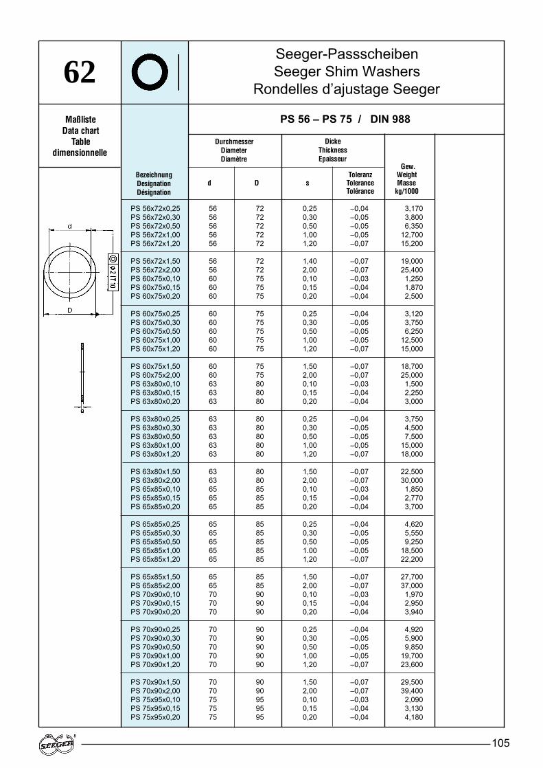
105
Seeger-PassscheibenSeeger Shim Washers
Rondelles d’ajustage Seeger62
BezeichnungDesignationDésignation
PS 56 – PS 75 / DIN 988
PS 56x72x0,25 56 72 0,25 –0,04 3,170PS 56x72x0,30 56 72 0,30 –0,05 3,800PS 56x72x0,50 56 72 0,50 –0,05 6,350PS 56x72x1,00 56 72 1,00 –0,05 12,700PS 56x72x1,20 56 72 1,20 –0,07 15,200
PS 56x72x1,50 56 72 1,40 –0,07 19,000PS 56x72x2,00 56 72 2,00 –0,07 25,400PS 60x75x0,10 60 75 0,10 –0,03 1,250PS 60x75x0,15 60 75 0,15 –0,04 1,870PS 60x75x0,20 60 75 0,20 –0,04 2,500
PS 60x75x0,25 60 75 0,25 –0,04 3,120PS 60x75x0,30 60 75 0,30 –0,05 3,750PS 60x75x0,50 60 75 0,50 –0,05 6,250PS 60x75x1,00 60 75 1,00 –0,05 12,500PS 60x75x1,20 60 75 1,20 –0,07 15,000
PS 60x75x1,50 60 75 1,50 –0,07 18,700PS 60x75x2,00 60 75 2,00 –0,07 25,000PS 63x80x0,10 63 80 0,10 –0,03 1,500PS 63x80x0,15 63 80 0,15 –0,04 2,250PS 63x80x0,20 63 80 0,20 –0,04 3,000
PS 63x80x0,25 63 80 0,25 –0,04 3,750PS 63x80x0,30 63 80 0,30 –0,05 4,500PS 63x80x0,50 63 80 0,50 –0,05 7,500PS 63x80x1,00 63 80 1,00 –0,05 15,000PS 63x80x1,20 63 80 1,20 –0,07 18,000
PS 63x80x1,50 63 80 1,50 –0,07 22,500PS 63x80x2,00 63 80 2,00 –0,07 30,000PS 65x85x0,10 65 85 0,10 –0,03 1,850PS 65x85x0,15 65 85 0,15 –0,04 2,770PS 65x85x0,20 65 85 0,20 –0,04 3,700
PS 65x85x0,25 65 85 0,25 –0,04 4,620PS 65x85x0,30 65 85 0,30 –0,05 5,550PS 65x85x0,50 65 85 0,50 –0,05 9,250PS 65x85x1,00 65 85 1.00 –0,05 18,500PS 65x85x1,20 65 85 1,20 –0,07 22,200
PS 65x85x1,50 65 85 1,50 –0,07 27,700PS 65x85x2,00 65 85 2,00 –0,07 37,000PS 70x90x0,10 70 90 0,10 –0,03 1,970PS 70x90x0,15 70 90 0,15 –0,04 2,950PS 70x90x0,20 70 90 0,20 –0,04 3,940
PS 70x90x0,25 70 90 0,25 –0,04 4,920PS 70x90x0,30 70 90 0,30 –0,05 5,900PS 70x90x0,50 70 90 0,50 –0,05 9,850PS 70x90x1,00 70 90 1,00 –0,05 19,700PS 70x90x1,20 70 90 1,20 –0,07 23,600
PS 70x90x1,50 70 90 1,50 –0,07 29,500PS 70x90x2,00 70 90 2,00 –0,07 39,400PS 75x95x0,10 75 95 0,10 –0,03 2,090PS 75x95x0,15 75 95 0,15 –0,04 3,130PS 75x95x0,20 75 95 0,20 –0,04 4,180
DickeThicknessEpaisseur
DurchmesserDiameterDiamètre
Gew.Toleranz Weight
d D s Tolerance MasseTolérance kg/1000
MaßlisteData chart
Tabledimensionnelle
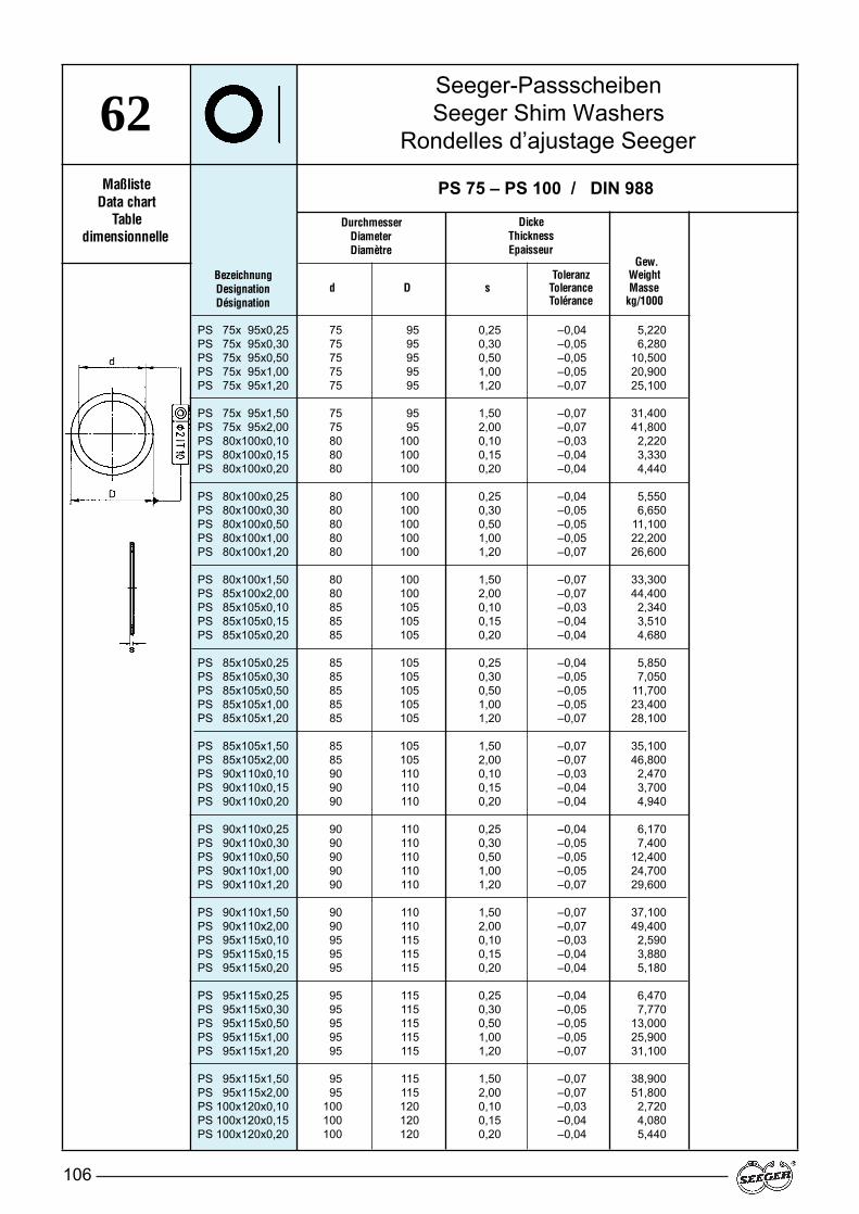
106
Seeger-PassscheibenSeeger Shim Washers
Rondelles d’ajustage Seeger62
BezeichnungDesignationDésignation
PS 75 – PS 100 / DIN 988
PS 75x 95x0,25 75 95 0,25 –0,04 5,220PS 75x 95x0,30 75 95 0,30 –0,05 6,280PS 75x 95x0,50 75 95 0,50 –0,05 10,500PS 75x 95x1,00 75 95 1,00 –0,05 20,900PS 75x 95x1,20 75 95 1,20 –0,07 25,100
PS 75x 95x1,50 75 95 1,50 –0,07 31,400PS 75x 95x2,00 75 95 2,00 –0,07 41,800PS 80x100x0,10 80 100 0,10 –0,03 2,220PS 80x100x0,15 80 100 0,15 –0,04 3,330PS 80x100x0,20 80 100 0,20 –0,04 4,440
PS 80x100x0,25 80 100 0,25 –0,04 5,550PS 80x100x0,30 80 100 0,30 –0,05 6,650PS 80x100x0,50 80 100 0,50 –0,05 11,100PS 80x100x1,00 80 100 1,00 –0,05 22,200PS 80x100x1,20 80 100 1,20 –0,07 26,600
PS 80x100x1,50 80 100 1,50 –0,07 33,300PS 85x100x2,00 80 100 2,00 –0,07 44,400PS 85x105x0,10 85 105 0,10 –0,03 2,340PS 85x105x0,15 85 105 0,15 –0,04 3,510PS 85x105x0,20 85 105 0,20 –0,04 4,680
PS 85x105x0,25 85 105 0,25 –0,04 5,850PS 85x105x0,30 85 105 0,30 –0,05 7,050PS 85x105x0,50 85 105 0,50 –0,05 11,700PS 85x105x1,00 85 105 1,00 –0,05 23,400PS 85x105x1,20 85 105 1,20 –0,07 28,100
PS 85x105x1,50 85 105 1,50 –0,07 35,100PS 85x105x2,00 85 105 2,00 –0,07 46,800PS 90x110x0,10 90 110 0,10 –0,03 2,470PS 90x110x0,15 90 110 0,15 –0,04 3,700PS 90x110x0,20 90 110 0,20 –0,04 4,940
PS 90x110x0,25 90 110 0,25 –0,04 6,170PS 90x110x0,30 90 110 0,30 –0,05 7,400PS 90x110x0,50 90 110 0,50 –0,05 12,400PS 90x110x1,00 90 110 1,00 –0,05 24,700PS 90x110x1,20 90 110 1,20 –0,07 29,600
PS 90x110x1,50 90 110 1,50 –0,07 37,100PS 90x110x2,00 90 110 2,00 –0,07 49,400PS 95x115x0,10 95 115 0,10 –0,03 2,590PS 95x115x0,15 95 115 0,15 –0,04 3,880PS 95x115x0,20 95 115 0,20 –0,04 5,180
PS 95x115x0,25 95 115 0,25 –0,04 6,470PS 95x115x0,30 95 115 0,30 –0,05 7,770PS 95x115x0,50 95 115 0,50 –0,05 13,000PS 95x115x1,00 95 115 1,00 –0,05 25,900PS 95x115x1,20 95 115 1,20 –0,07 31,100
PS 95x115x1,50 95 115 1,50 –0,07 38,900PS 95x115x2,00 95 115 2,00 –0,07 51,800PS 100x120x0,10 100 120 0,10 –0,03 2,720PS 100x120x0,15 100 120 0,15 –0,04 4,080PS 100x120x0,20 100 120 0,20 –0,04 5,440
DickeThicknessEpaisseur
DurchmesserDiameterDiamètre
Gew.Toleranz Weight
d D s Tolerance MasseTolérance kg/1000
MaßlisteData chart
Tabledimensionnelle
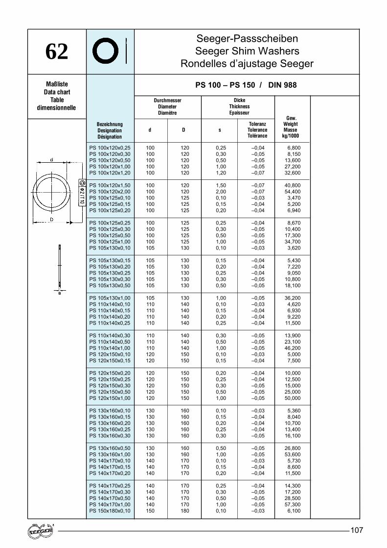
107
Seeger-PassscheibenSeeger Shim Washers
Rondelles d’ajustage Seeger62
BezeichnungDesignationDésignation
PS 100 – PS 150 / DIN 988
PS 100x120x0,25 100 120 0,25 –0,04 6,800PS 100x120x0,30 100 120 0,30 –0,05 8,150PS 100x120x0,50 100 120 0,50 –0,05 13,600PS 100x120x1,00 100 120 1,00 –0,05 27,200PS 100x120x1,20 100 120 1,20 –0,07 32,600
PS 100x120x1,50 100 120 1,50 –0,07 40,800PS 100x120x2,00 100 120 2,00 –0,07 54,400PS 100x125x0,10 100 125 0,10 –0,03 3,470PS 100x125x0,15 100 125 0,15 –0,04 5,200PS 100x125x0,20 100 125 0,20 –0,04 6,940
PS 100x125x0,25 100 125 0,25 –0,04 8,670PS 100x125x0,30 100 125 0,30 –0,05 10,400PS 100x125x0,50 100 125 0,50 –0,05 17,300PS 100x125x1,00 100 125 1,00 –0,05 34,700PS 105x130x0,10 105 130 0,10 –0,03 3,620
PS 105x130x0,15 105 130 0,15 –0,04 5,430PS 105x130x0,20 105 130 0,20 –0,04 7,220PS 105x130x0,25 105 130 0,25 –0,04 9,050PS 105x130x0,30 105 130 0,30 –0,05 10,800PS 105x130x0,50 105 130 0,50 –0,05 18,100
PS 105x130x1,00 105 130 1,00 –0,05 36,200PS 110x140x0,10 110 140 0,10 –0,03 4,620PS 110x140x0,15 110 140 0,15 –0,04 6,930PS 110x140x0,20 110 140 0,20 –0,04 9,220PS 110x140x0,25 110 140 0,25 –0,04 11,500
PS 110x140x0,30 110 140 0,30 –0,05 13,900PS 110x140x0,50 110 140 0,50 –0,05 23,100PS 110x140x1,00 110 140 1,00 –0,05 46,200PS 120x150x0,10 120 150 0,10 –0,03 5,000PS 120x150x0,15 120 150 0,15 –0,04 7,500
PS 120x150x0,20 120 150 0,20 –0,04 10,000PS 120x150x0,25 120 150 0,25 –0,04 12,500PS 120x150x0,30 120 150 0,30 –0,05 15,000PS 120x150x0,50 120 150 0,50 –0,05 25,000PS 120x150x1,00 120 150 1,00 –0,05 50,000
PS 130x160x0,10 130 160 0,10 –0,03 5,360PS 130x160x0,15 130 160 0,15 –0,04 8,040PS 130x160x0,20 130 160 0,20 –0,04 10,700PS 130x160x0,25 130 160 0,25 –0,04 13,400PS 130x160x0,30 130 160 0,30 –0,05 16,100
PS 130x160x0,50 130 160 0,50 –0,05 26,800PS 130x160x1,00 130 160 1,00 –0,05 53,600PS 140x170x0,10 140 170 0,10 –0,03 5,730PS 140x170x0,15 140 170 0,15 –0,04 8,600PS 140x170x0,20 140 170 0,20 –0,04 11,500
PS 140x170x0,25 140 170 0,25 –0,04 14,300PS 140x170x0,30 140 170 0,30 –0,05 17,200PS 140x170x0,50 140 170 0,50 –0,05 28,500PS 140x170x1,00 140 170 1,00 –0,05 57,300PS 150x180x0,10 150 180 0,10 –0,03 6,100
DickeThicknessEpaisseur
DurchmesserDiameterDiamètre
Gew.Toleranz Weight
d D s Tolerance MasseTolérance kg/1000
MaßlisteData chart
Tabledimensionnelle

108
Seeger-PassscheibenSeeger Shim Washers
Rondelles d’ajustage Seeger62
BezeichnungDesignationDésignation
PS 150 – PS 170 / DIN 988
PS 150x180x0,15 150 180 0,15 –0,04 9,150PS 150x180x0,20 150 180 0,20 –0,04 12,200PS 150x180x0,25 150 180 0,25 –0,04 15,200PS 150x180x0,30 150 180 0,30 –0,05 18,300PS 150x180x0,50 150 180 0,50 –0,05 30,500
PS 150x180x1,00 150 180 1,00 –0,05 61,000PS 160x190x0,10 160 190 0,10 –0,03 6,470PS 160x190x0,15 160 190 0,15 –0,04 9,700PS 160x190x0,20 160 190 0,20 –0,04 12,900PS 160x190x0,25 160 190 0,25 –0,04 16,200
PS 160x190x0,30 160 190 0,30 –0,05 19,400PS 160x190x0,50 160 190 0,50 –0,05 32,300PS 160x190x1,00 160 190 1,00 –0,05 64,700PS 170x200x0,10 170 200 0,10 –0,03 6,850PS 170x200x0,15 170 200 0,15 –0,04 10,300
PS 170x200x0,20 170 200 0,20 –0,04 13,700PS 170x200x0,25 170 200 0,25 –0,04 17,100PS 170x200x0,30 170 200 0,30 –0,05 20,600PS 170x200x0,50 170 200 0,50 –0,05 34,300PS 170x200x1,00 170 200 1,00 –0,05 68,500
DickeThicknessEpaisseur
DurchmesserDiameterDiamètre
Gew.Toleranz Weight
d D s Tolerance MasseTolérance kg/1000
MaßlisteData chart
Tabledimensionnelle
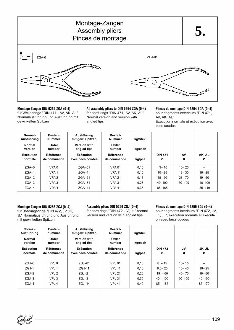
109
5.
Normal- Bestell- Ausführung Bestell-Ausführung Nummer mit gew. Spitzen Nummer kg/Stck.
Normal Order Version with Orderversion number angled tips number kg/each
Exécution Référence Exécution Référence DIN 471 AV AK, ALnormale de commande avec becs coudés de commande kg/pce ø ø ø
ZGA–0 VPA 0 ZGA–01 VPA 01 0,10 3– 10 10– 20 –ZGA–1 VPA 1 ZGA–11 VPA 11 0,10 10– 25 18– 30 16– 25ZGA–2 VPA 2 ZGA–21 VPA 21 0,18 18– 60 28– 70 19– 60ZGA–3 VPA 3 ZGA–31 VPA 31 0,28 40–100 50–100 40–100ZGA–4 VPA 4 ZGA–41 VPA 41 0,36 85–165 – 85–140
Montage-ZangenAssembly pliers
Pinces de montage
Montage-Zangen DIN 5256 ZGJ (0–4)für Bohrungsringe "DIN 472, JV JK,JL" Normalausführung und Ausführungmit gewinkelten Spitzen
Pinces de montage DIN 5254 ZGA (0–4)pour segments extérieurs "DIN 471,AV, AK, AL" Exécution normale et exécution avecbecs coudés
All assembly pliers to DIN 5254 ZGA (0-4)for shaft rings "DIN 471, AV, AK, AL" Normal version and version with angled tips
Assembly pliers DIN 5256 ZGJ (0–4)for bore rings "DIN 472, JV, JL" normalversion and version with angled tips
Pinces de montage DIN 5256 ZGJ (0–4)pour segments intérieurs "DIN 472, JV,JK, JL", exécution normale et exécuti-on avec becs coudés
Montage-Zangen DIN 5254 ZGA (0-4) für Wellenringe "DIN 471, AV, AK, AL" Normalausführung und Ausführung mitgewinkelten Spitzen
Normal- Bestell- Ausführung Bestell-Ausführung nummer mit gew. Spitzen Nummer kg/Stck.
Normal Order Version with Orderversion number angled tips number kg/each
Exécution Référence Exécution Référence DIN 472 JV JK, JLnormale de commande avec becs coudés de commande kg/pce ø ø ø
ZGJ–0 VPJ 0 ZGJ–01 VPJ 01 0,10 8 – 15 10– 15 –ZGJ-1 VPJ 1 ZGJ-11 VPJ 11 0,10 9,5– 25 16– 40 16– 25ZGJ–2 VPJ 2 ZGJ–21 VPJ 21 0,20 19 – 60 40– 70 19– 60ZGJ–3 VPJ 3 ZGJ–31 VPJ 31 0,30 40 –100 50–100 40–100ZGJ–4 VPJ 4 ZGJ–14 VPJ 41 0,42 85 –165 – 85–170
ZGA-01 ZGJ-01

110
5.
ZGJ (5–6) für Bohrungsringe "DIN 472, JK, JL" wahlweise mit aus-wechselbaren Spitzen für "J"-Ringe.Normalausführung und Ausführung mitgewinkelten Spitzen
ZGA (5–6) pour segments extérieurs"DIN 471,AW, AK, AL", en option avecbecs interchangeables pour anneaux"A". Exécution normale et exécutionavec becs coudés
ZGA (5–6) for shaft rings "DIN 471,AW, AK, AL", optionally with interchan-geable tips for "A" rings. Normal versi-on and version with angled tips
Normal- Bestell- Ausführung Bestell-Ausführung nummer mit gew. Spitzen Nummer kg/Stck.
Normal Order Version with Orderversion number angled tips number kg/each
Exécution Référence Exécution Référence DIN 471 AK, ALnormale de commande avec becs coudés de commande kg/pce ø ø
ZGA–5 VPA 5 ZGA–51 VPA 51 1,30 122–300 > 120ZGA-6 VPA 6 ZGA-61 VPA 62 1,40 252–400 –
ZGJ (5–6) for bore rings "DIN 472, JK, JL", optionally with interchangea-ble tips for "J" rings. Normal versionand version with angled tips
ZGJ (5-6) pour segments intérieurs"DIN 472, JK, JL", en option avec becsinterchangeables pour anneaux "J".Exécution normale et exécution avecbecs coudés
ZGA (5-6) für Wellenringe "DIN 471,AW, AK, AL" wahlweise mit auswech-selbaren Spitzen für "A"-Ringe.Normalausführung und Ausführung mitgewinkelten Spitzen
Normal- Bestell- Ausführung Bestell- kg/Stck.Ausführung Nummer mit gew. Spitzen Nummer
Normal Order Version with Order kg/eachversion number angled tips number
Exécution Référence Exécution Référence kg/pce DIN 472normale de commande avec becs coudés de commande JZ, JW ø JK, JL ø
ZGJ–5 VPJ 5 ZGJ-51 VPJ 51 1,30 122–300 > 120ZGJ–6 VPJ 6 ZGJ–61 VPJ 61 1,30 252–400 –
ZGA-51 / 61ZGJ-51 / 61
Montage-ZangenAssembly pliers
Pinces de montage
Eine Ratsche hält die ZangenZGA/ZGJ in jeder gewünschtenStellung unter Spannung. Für dieZangenkörper sind auch kleineSonderspitzen lieferbar.
Zange für Ringe DIN 471/472 über 400 mm auf Anfrage.
A rachet keeps the ZGA/ZGJ plierstensioned in all desired positions.Small special tips can also be suppliedfor the basic plier bodies.
Pincers for rings DIN 471/472 over 400 mm upon request.
Un cliquet maintient les pincesZGA/ZGJ à toutes les positions sou-haitées. De petits becs spéciaux sontégalement livrables pour les pinces.
Pince pour circlips DIN 471/472 deplus de 400 mm sur demande.

111
5.Ringspender und Greifer
Ring Dispensers and applicatorsDistributeurs et fourchettes de pose
Ringspender (Bild 1)Sicherungsscheiben DIN 6799
Anwendung:für Sicherungsscheiben RA 1,2 � RA 10
Die auf Steckleisten gestapeltenSicherungsscheiben werden mit derSteckleiste auf das Gerät aufgesetztund die Scheiben mit einem Greiferentnommen.Greifer siehe zugehörige Maßliste 32
Ringspender (Bild 2)Halbmondringe
Anwendung: für Halbmondringe H 3 � H 20
Die mit einem Klebestreifen zusam-mengehaltenen Ringe* werden auf dasGerät aufgesteckt, der Klebestreifenabgezogen und die Ringe mit einemGreifer entnommen.Greifer siehe zugehörige Maßliste 33
* Ringe nur phosphatiert, nicht geölt
Ring dispenser (figure 1)Retaining rings to DIN 6799
Application:for retaining rings RA 1,2 � RA 10
The retaining rings stacked on inserti-on strips are fitted on the device usingthe insertion strip and are removedusing an applicator.Gripper see accessory dimension list 32
Ring dispenser (figure 2)Crescent rings
Application: for crescent rings H 3 � H 20
The rings* held together by an adhesi-ve tape are slid onto the device, theadhesive tape is removed and therings are removed from the dispenserusing an applicator.
* Phosphated only, not oiled
Distributeur MRA (figure 1)Colliers d'épaulement DIN 6799
Application:Pour colliers d'épaulement RA 1,2 �RA 10
Les colliers d'épaulement sont mis enplace sur l'appareil avec la tige etprélevés à l'aide d'une fourchette depose, type GRA.Fourchette de pose, voir la liste des di-mensions 32 correspondante
Distributeur MWH (figure 2)Croissants
Application: Pour croissants H 3 � H 20
Les croisssants maintenus empilés*par une bande adhésive sont mis enplace sur l'appareil. On retire ensuitela bande adhésive puis on prélève lescroissants à l'aide d'une fourchette depose, type GRH
* Segments seulement phosphatés, non huilés
– 1 – – 2 –
112
6.6.1 Qualitätsforderungen
Befestigungselemente werden weltweit in allen Bereichen derIndustrie und insbesondere im Auto-mobilbau mit Erfolg eingesetzt. Sie wer-den häufig in Sicherheitskonstruktionenwie z.B. Lenkungen oder Bremsen ver-wendet und unterliegen über Jahre hin-weg großen Beanspruchungen.Neben den in der DIN 471/472 festge-legten Qualitätskriterien, die in vielenFällen den Ansprüchen der Anwendergenügen und Basis unserer Angebotesind, können für spezielle Anforderungenfür den jeweiligen Zweck abgestimmteVereinbarungen getroffen werden.Seeger-Orbis verfügt über umfangrei-che Erfahrungen auf dem Gebiet derSicherungselemente und berät Sie ger-ne bei Ihrem Anwendungsfall. Die tech-nische Beratung steht auch für dieFestlegung von spezifischen Qualitäts-merkmalen unter Berücksichtigung ihrerindividuellen Einbau- und Montage-situationen zu Ihrer Verfügung.
Nutzen Sie unsere Erfahrungen, sprechen Sie mit uns.
Die Zuverlässigkeit der Seeger-Pro-dukte ist das Ergebnis konsequenterEntwicklung, prozeßsicherer Ferti-gungsanlagen und eines ausgereiftenQualitätssicherungs-Systems.Das für die Herstellung eingesetzte Vor-material unterliegt den höchsten Qua-litätsansprüchen. Die Qualitätssiche-rung erfolgt in jeder Fertigungsstufe: vomWalzen, Wickeln, Stanzen, der Wärme-behandlung und von der Oberflächen-Technik bis zu den V erpackungsanla-gen und dem Warenausgang.Zertifiziert nach ISO/TS 16949 sind alleVerfahren und Abläufe festgelegt. Fürjede Produktgruppe existieren Qualitäts-management-Pläne mit Prüfabläufenund Prüffrequenzen.Alle Fertigungprozesse werden mittelsstatistischer Prozeßlenkung (SPC)überwacht und dokumentiert. SPC istein Teil des computerunterstützten Qua-litätssicherungs-Systems (CAQ), so daßalle wesentlichen Qualitätsdaten erfaßtund dokumentiert werden können.
Das Qualitätsmanagement-Systemvon Seeger-Orbis erfüllt die höch-sten Ansprüche der internationalenAutomobilindustrie und ist zertifi-ziert nach ISO / TS 16949.
QualitätQualityQualité
6.1 Quality requirements
FasteningsFastenings are used successfullythroughout the world in all areas of in-dustry and especially automobile con-struction. They are often used in safetycomponents such as steering and bra-kes and are subject to great stressesover many years. In addition to the quality criteria laid do-wn in DIN 471/472, which in many ca-ses are suf ficient to meet the require-ments of the user and form the basis ofour quotations, arrangements can alsobe agreed regarding special require-ments for particular applications.Seeger-Orbis has vast experience in thefield of fastenings and will gladly provi-de advice for your application. Technicaladvice can also be given on specificquality characteristics regarding yourparticular fitting or assembly applicati-ons.
Benefit from our experience. Feelfree to consult us.
The reliability of Seeger products is theresult of consistent development, pro-duction facilities with secure processesand a fully developed quality assurancesystem. Raw materials used in produc-tion are subject to the highest quality re-quirements. Quality assurance is part ofevery stage in production: from rolling,winding, pressing, during heat treatmentand for surface engineering to the pack-aging plants and dispatch.All processes and sequences are laiddown and certified by ISO/TS 16949.For each product group there are quali-ty management plans with testing se-quences and intervals.All production processes are monitoredand documented by means of statisticalprocess control (SPC) which is a part ofthe computer supported quality assu-rance system (CAQ) so that all signifi-cant quality data can be acquired anddocumented.
The Quality-Management system ofSeeger-Orbis meets the highestrequirements of the internationalautomobile industry and is certifiedaccording to ISO / TS 16949.
6.1 Critères de qualité
Éléments de fixationLes éléments de fixation sont utilisés dansle monde entier dans tous les secteurs del’industrie et en particulier dans l’industrieautomobile. Ils sont souvent utilisés dansdes constructions de sécurité comme lesdirections ou les freins et sont soumis du-rant des années à de grandes sollicitations.En plus des critères de qualité déterminéspar DIN 471/472 qui suf fisent dans denombreux cas aux exigences des utilisa-teurs et sont la base de nos offres, des ac-cords particuliers peuvent être concluspour des exigences spéciales en fonctiond’une utilisation particulière.Seeger-Orbis dispose d’une expériencetrès étendue dans le domaine des élé-ments de sécurité et vous conseille volon-tiers dans votre cas d’application. Le con-seil technique se trouve également à vot-re disposition pour des caractéristiques dequalité spécifiques en tenant compte devos conditions particulières de montage.
Profitez de notre expérience – consultez-nous.
La fiabilité des produits Seeger est le ré-sultat d'un travail systématique de mise aupoint et n'est possible que grâce à des in-stallations de fabrication assurant des pro-cessus sûrs et à un système de gestion dela qualité très mûri. Les matériaux utiliséspour la fabrication répondent aux plus hau-tes exigences de qualité.Des contrôles de qualité sont ef fectués àchaque niveau de fabrication : depuis lelaminage, le bobinage, l’estampage, letraitement thermique et le traitement dessurfaces jusqu'aux installations d'emballa-ge et à l'expédition des marchandises.Certifiés selon ISO/TS, tous les procédéset processus sont déterminés. Pour cha-que groupe de produit il existe des plansde gestion de la qualité comportant desprocédés et des fréquences de vérificati-on.Tous les processus de fabrication sont sur-veillés et documentés par l’emploi du con-trôle statistique des processus (CSP). Lecontrôle statistique des processus fait par-tie d’un système d’ensemble de gestion dela qualité assistée par ordinateur (CAO)qui permet de saisir et de documenter tou-tes les données importantes de qualité.
Le système de gestion de la qualitéde Seeger-Orbis répond aux hautesexigences de l’industrie automobileinternationale et est certifié selonISO / TS 16949.
113
6.2 Materials
Seeger retaining systems are manufac-tured as standard from high-gradespring steels which are best suitable forthe special characteristics of the varioustypes. Most of the rings and discs are coatedby heat treatment, so that they can co-pe with high axial forces when locatedin their groove. The hardness of the lar-ger rings is lower because they are sub-ject to less strain in the assembly: Thehardness of rings are indicated inRockwell or V ickers. The hardness ofrings with a thickness of < 1.1 mm canonly be measured with the assistance ofVickers.
Carbon spring steelThe demands placed on the material,such as a high modulus of elasticity ,high yield point, high elastic elongationand good hardening abilities, are achie-ved best by spring steels in accordancewith DIN EN 10132-1/4 (DIN 17222).Thematerial C 75S, material No. 1.1248with a low phosphorus and sulphur con-tent is especially used to manufactureSeeger rings. The Materials C 58D (1.0609), C 58D(1.1212), old: MK 58, DIN EN 10 016-2/-4* and spring steel wire in accor-dance with DIN EN 10270-1 (DIN17223-1) are also used to manufactureSeeger retaining systems.Patented drawn spring wire similar toDIN EN 10270-1 in various profiles canbe produced in our own rolling plant.
6.WerkstoffeMaterialsMatières
6.2 Werkstoffe
Die Seeger-Befestigungselemente wer-den serienmäßig aus hochwertigenFederstählen hergestellt, die für die spe-ziellen Eigenschaften der verschiede-nen Ausführungsarten am besten ge-eignet sind.Die meisten Ringe und Scheiben wer-den in der Wärmebehandlung vergütet,so daß sie bei Sitz in der Nut hohe axia-le Kräfte aufnehmen können. Die Härtevon größeren Ringen liegt niedriger, dasie bei der Montage nicht so hoch be-ansprucht werden. Die Härte der Ringewird in Rockwell oder V ickers angege-ben. Bei Ringen mit einer Dicke < 1,1mm ist die Härtemessung nur mit Hilfevon Vickers möglich.
Kohlenstoff-FederstahlDie an den W erkstoff gestellten Anfor-derungen, wie hohe elastische Deh-nung und gute Härtbarkeit, werdendurch die Feder stähle nach DIN EN10132-1/4 (DIN 17222)am besten erfüllt.Zur Herstellung von Seeger-Ringenwird speziell der Werkstoff C 75S,Werkstoffnummer 1.1248 mit gerin-gem Phosphor- und Schwefelgehaltverwendet. W eiterhin werden für dieHerstellung von Seeger-Befestigungs-elementen auch die Werkstoffe C 58D(1.0609), C 58D2 (1.1212) , alt: MK 58,DIN EN 10 016-2/-4* und Federstahl-draht nach DIN EN 10270-1 (DIN17223-1) eingesetzt.Auf eigenen W alzanlagen kann paten-tiert gezogener Federstahldraht, ähnlichDIN EN 10270-1, zu verschiedenenProfilen gewalzt werden.
Werkstoffe nach / Materials in accordance with / Matières selon: DIN EN 10132-4 DIN EN 10016-4* DIN EN 10016-2*
Bezeichnung / Designation / Désignation C 75 S C 58 D2 C 58 DWerkstoff-Nr. / Material No. / N° de Matière 1.1248 1.1212 1.0609
C % 0,70 – 0,80 0,56 – 0,60 0,55 – 0,60Mn % 0,60 – 0,90 0,50 – 0,70 0,50 – 0,80Si % 0,15 – 0,35 0,10 – 0,30 0,10 – 0,30P % ≤ 0,025 ≤ 0,020 ≤ 0,035S % ≤ 0,025 ≤ 0,025 ≤ 0,035
E-Modul / E-Mod of elasticity / E-Module d'élast. [N/mm2] 210.000 210.000 210.000spez. Gew. / specific gravity / Masse spécif. [g/cm3] 7,85 7,85 7,85Re [N/mm2] 1500 1450 1450Rm [N/mm2] 1750 1700 1700� [%] 0,715 0,69 0,69
6.2 Matières
Les éléments de fixation Seeger sont fa-briqués en série avec des aciers à res-sort de qualité supérieure, parfaitementadaptés aux différentes exécutions et àleurs propriétés spécifiques. La plupart des segments et rondellessont trempés pendant le traitement ther-mique, de façon à pouvoir supporter desefforts axiaux importants lorsqu'ils sontinstallés dans la gorge. La dureté dessegments plus grands est plus basse,puisque, lors du montage, ils subissentde moins grandes contraintes: La duretédes segments est indiquée selonRockwell ou V ickers. Dans le cas dessegments d'une épaisseur < 1.1 mm, ladureté ne peut être mesurée qu’à l’aidedu système Vickers.
Acier à ressort au carboneLes aciers à ressort selon DIN EN 10132-1/4 (DIN 17222) sont parfaitement adap-tés aux exigences (coefficient d'élasticitéélevé, limite d'élasticité élevée, allonge-ment élastique et bonne aptitude à latrempe). La matière C 75S, n° de ma-tière 1.1248, ayant une faible teneur enphosphore et en soufre, est utilisée toutspécialement pour la fabrication des seg-ments Seeger . Les matières C 58D(1.0609), C 58D2 (1.1212), ancienne-ment: MK 58, DIN EN 10 016-2/-4* etle fil d'acier à ressort selon DIN EN10270-1 (DIN 17223-1) sont égalementutilisés pour la fabrication des élémentsde fixation Seeger.Dans nos propres la-minoirs, l’acier à ressort tiré de manièrebrevetée, semblablement à DIN EN10270-1, peut être laminé selon diversprofils.
*nur Angaben zur chemischen Analyse · *Specifications only for chemical analysis · *Spécifications seulement pour analyse c himique
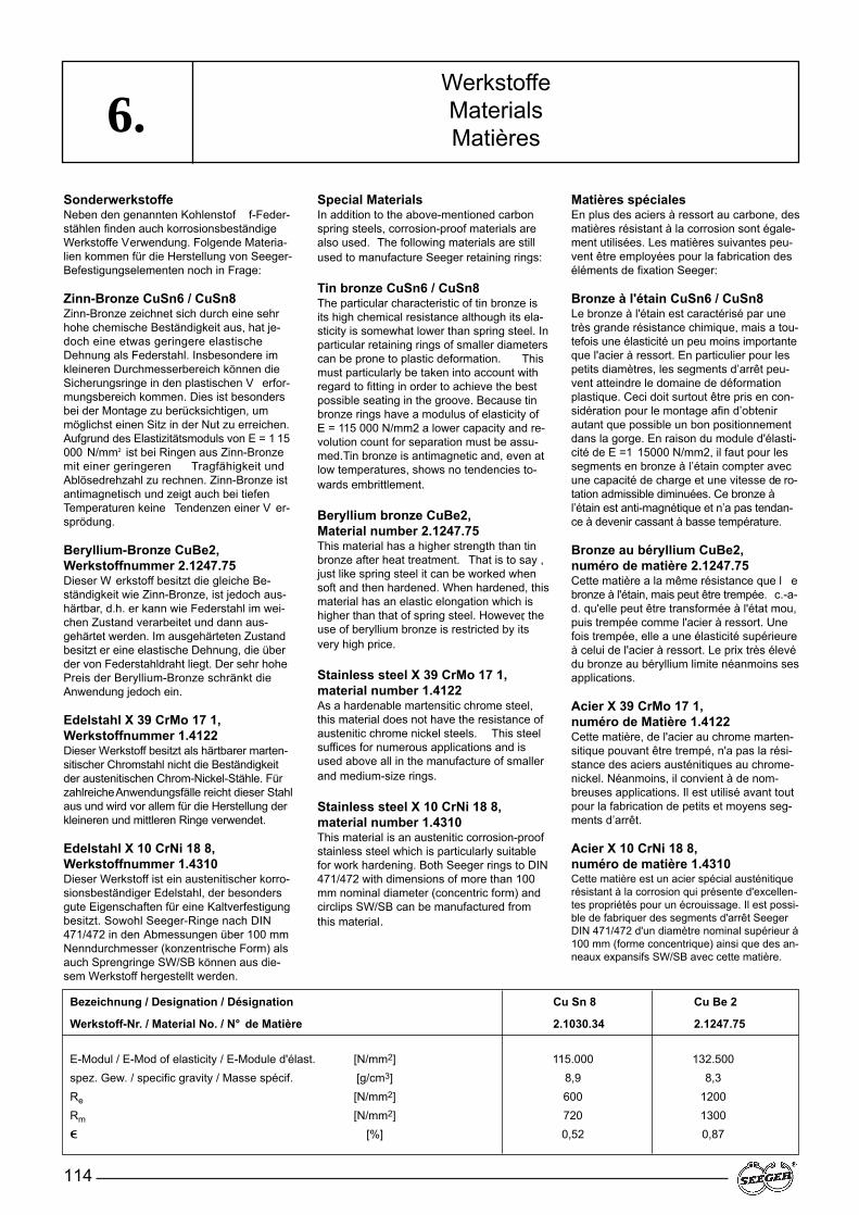
114
6.SonderwerkstoffeNeben den genannten Kohlenstof f-Feder-stählen finden auch korrosionsbeständigeWerkstoffe Verwendung. Folgende Materia-lien kommen für die Herstellung von Seeger-Befestigungselementen noch in Frage:
Zinn-Bronze CuSn6 / CuSn8Zinn-Bronze zeichnet sich durch eine sehrhohe chemische Beständigkeit aus, hat je-doch eine etwas geringere elastischeDehnung als Federstahl. Insbesondere imkleineren Durchmesserbereich können dieSicherungsringe in den plastischen V erfor-mungsbereich kommen. Dies ist besondersbei der Montage zu berücksichtigen, ummöglichst einen Sitz in der Nut zu erreichen.Aufgrund des Elastizitätsmoduls von E = 1 15000 N/mm2 ist bei Ringen aus Zinn-Bronzemit einer geringeren Tragfähigkeit undAblösedrehzahl zu rechnen. Zinn-Bronze istantimagnetisch und zeigt auch bei tiefenTemperaturen keine Tendenzen einer V er-sprödung.
Beryllium-Bronze CuBe2,Werkstoffnummer 2.1247.75Dieser W erkstoff besitzt die gleiche Be-ständigkeit wie Zinn-Bronze, ist jedoch aus-härtbar, d.h. er kann wie Federstahl im wei-chen Zustand verarbeitet und dann aus-gehärtet werden. Im ausgehärteten Zustandbesitzt er eine elastische Dehnung, die überder von Federstahldraht liegt. Der sehr hohePreis der Beryllium-Bronze schränkt dieAnwendung jedoch ein.
Edelstahl X 39 CrMo 17 1,Werkstoffnummer 1.4122Dieser Werkstoff besitzt als härtbarer marten-sitischer Chromstahl nicht die Beständigkeitder austenitischen Chrom-Nickel-Stähle. Fürzahlreiche Anwendungsfälle reicht dieser Stahlaus und wird vor allem für die Herstellung derkleineren und mittleren Ringe verwendet.
Edelstahl X 10 CrNi 18 8,Werkstoffnummer 1.4310Dieser Werkstoff ist ein austenitischer korro-sionsbeständiger Edelstahl, der besondersgute Eigenschaften für eine Kaltverfestigungbesitzt. Sowohl Seeger-Ringe nach DIN471/472 in den Abmessungen über 100 mmNenndurchmesser (konzentrische Form) alsauch Sprengringe SW/SB können aus die-sem Werkstoff hergestellt werden.
Special MaterialsIn addition to the above-mentioned carbonspring steels, corrosion-proof materials arealso used. The following materials are stillused to manufacture Seeger retaining rings:
Tin bronze CuSn6 / CuSn8The particular characteristic of tin bronze isits high chemical resistance although its ela-sticity is somewhat lower than spring steel. Inparticular retaining rings of smaller diameterscan be prone to plastic deformation. Thismust particularly be taken into account withregard to fitting in order to achieve the bestpossible seating in the groove. Because tinbronze rings have a modulus of elasticity ofE = 115 000 N/mm2 a lower capacity and re-volution count for separation must be assu-med.Tin bronze is antimagnetic and, even atlow temperatures, shows no tendencies to-wards embrittlement.
Beryllium bronze CuBe2, Material number 2.1247.75This material has a higher strength than tinbronze after heat treatment. That is to say ,just like spring steel it can be worked whensoft and then hardened. When hardened, thismaterial has an elastic elongation which ishigher than that of spring steel. However, theuse of beryllium bronze is restricted by itsvery high price.
Stainless steel X 39 CrMo 17 1, material number 1.4122As a hardenable martensitic chrome steel,this material does not have the resistance ofaustenitic chrome nickel steels. This steelsuffices for numerous applications and isused above all in the manufacture of smallerand medium-size rings.
Stainless steel X 10 CrNi 18 8, material number 1.4310This material is an austenitic corrosion-proofstainless steel which is particularly suitablefor work hardening. Both Seeger rings to DIN471/472 with dimensions of more than 100mm nominal diameter (concentric form) andcirclips SW/SB can be manufactured fromthis material.
Matières spécialesEn plus des aciers à ressort au carbone, desmatières résistant à la corrosion sont égale-ment utilisées. Les matières suivantes peu-vent être employées pour la fabrication deséléments de fixation Seeger:
Bronze à l'étain CuSn6 / CuSn8Le bronze à l'étain est caractérisé par unetrès grande résistance chimique, mais a tou-tefois une élasticité un peu moins importanteque l'acier à ressort. En particulier pour lespetits diamètres, les segments d’arrêt peu-vent atteindre le domaine de déformationplastique. Ceci doit surtout être pris en con-sidération pour le montage afin d’obtenirautant que possible un bon positionnementdans la gorge. En raison du module d'élasti-cité de E =1 15000 N/mm2, il faut pour lessegments en bronze à l’étain compter avecune capacité de charge et une vitesse de ro-tation admissible diminuées. Ce bronze àl’étain est anti-magnétique et n’a pas tendan-ce à devenir cassant à basse température.
Bronze au béryllium CuBe2, numéro de matière 2.1247.75Cette matière a la même résistance que l ebronze à l'étain, mais peut être trempée. c.-a-d. qu'elle peut être transformée à l'état mou,puis trempée comme l'acier à ressort. Unefois trempée, elle a une élasticité supérieureà celui de l'acier à ressort. Le prix très élevédu bronze au béryllium limite néanmoins sesapplications.
Acier X 39 CrMo 17 1, numéro de Matière 1.4122Cette matière, de l'acier au chrome marten-sitique pouvant être trempé, n'a pas la rési-stance des aciers austénitiques au chrome-nickel. Néanmoins, il convient à de nom-breuses applications. Il est utilisé avant toutpour la fabrication de petits et moyens seg-ments d’arrêt.
Acier X 10 CrNi 18 8,numéro de matière 1.4310Cette matière est un acier spécial austénitiquerésistant à la corrosion qui présente d'excellen-tes propriétés pour un écrouissage. Il est possi-ble de fabriquer des segments d'arrêt SeegerDIN 471/472 d'un diamètre nominal supérieur à100 mm (forme concentrique) ainsi que des an-neaux expansifs SW/SB avec cette matière.
Bezeichnung / Designation / Désignation Cu Sn 8 Cu Be 2
Werkstoff-Nr. / Material No. / N° de Matière 2.1030.34 2.1247.75
E-Modul / E-Mod of elasticity / E-Module d'élast. [N/mm2] 115.000 132.500spez. Gew. / specific gravity / Masse spécif. [g/cm3] 8,9 8,3Re [N/mm2] 600 1200Rm [N/mm2] 720 1300� [%] 0,52 0,87
WerkstoffeMaterialsMatières
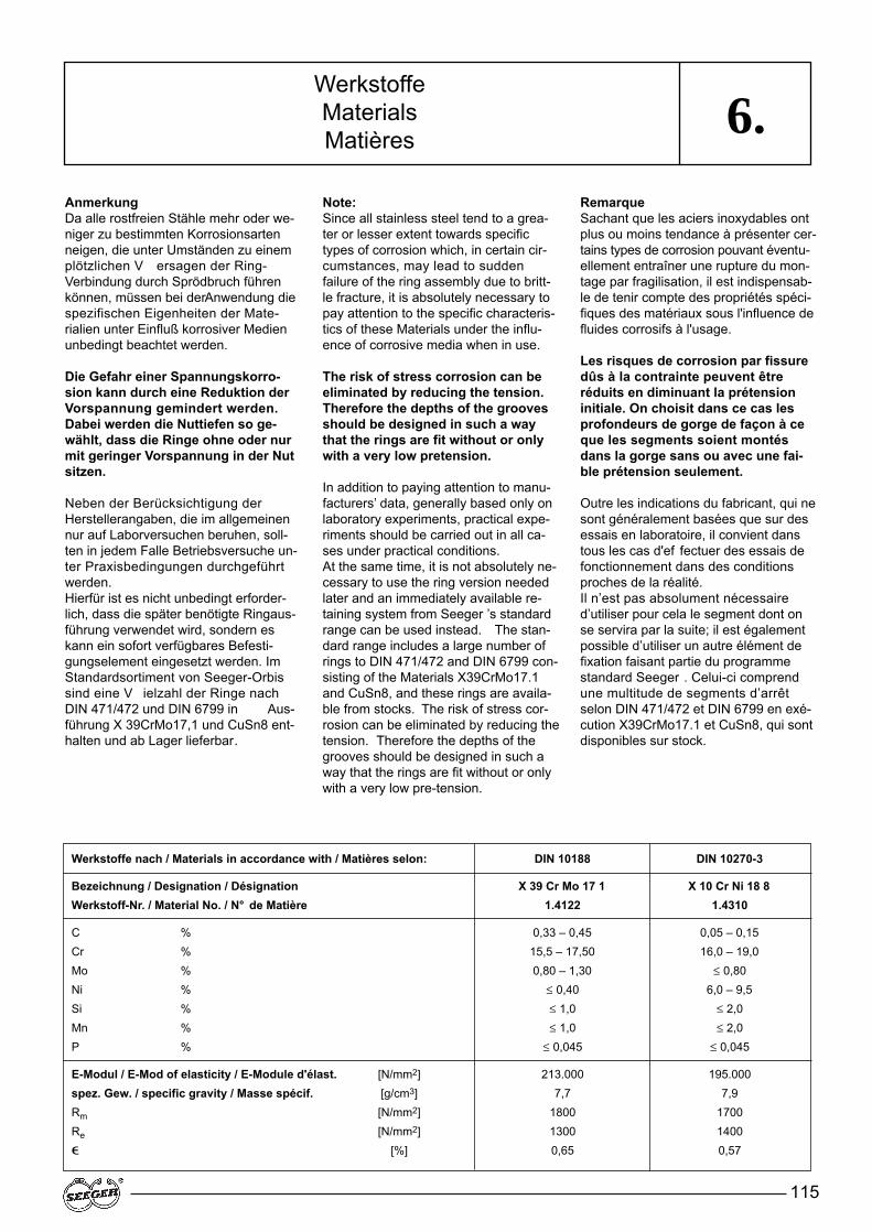
115
6.AnmerkungDa alle rostfreien Stähle mehr oder we-niger zu bestimmten Korrosionsartenneigen, die unter Umständen zu einemplötzlichen V ersagen der Ring-Verbindung durch Sprödbruch führenkönnen, müssen bei der Anwendung diespezifischen Eigenheiten der Mate-rialien unter Einfluß korrosiver Medienunbedingt beachtet werden.
Die Gefahr einer Spannungskorro-sion kann durch eine Reduktion derVorspannung gemindert werden.Dabei werden die Nuttiefen so ge-wählt, dass die Ringe ohne oder nurmit geringer Vorspannung in der Nutsitzen.
Neben der Berücksichtigung derHerstellerangaben, die im allgemeinennur auf Laborversuchen beruhen, soll-ten in jedem Falle Betriebsversuche un-ter Praxisbedingungen durchgeführtwerden.Hierfür ist es nicht unbedingt erforder-lich, dass die später benötigte Ringaus-führung verwendet wird, sondern eskann ein sofort verfügbares Befesti-gungselement eingesetzt werden. ImStandardsortiment von Seeger-Orbissind eine V ielzahl der Ringe nachDIN 471/472 und DIN 6799 in Aus-führung X 39CrMo17,1 und CuSn8 ent-halten und ab Lager lieferbar.
Note:Since all stainless steel tend to a grea-ter or lesser extent towards specifictypes of corrosion which, in certain cir-cumstances, may lead to suddenfailure of the ring assembly due to britt-le fracture, it is absolutely necessary topay attention to the specific characteris-tics of these Materials under the influ-ence of corrosive media when in use.
The risk of stress corrosion can beeliminated by reducing the tension.Therefore the depths of the groovesshould be designed in such a waythat the rings are fit without or onlywith a very low pretension.
In addition to paying attention to manu-facturers’ data, generally based only onlaboratory experiments, practical expe-riments should be carried out in all ca-ses under practical conditions.At the same time, it is not absolutely ne-cessary to use the ring version neededlater and an immediately available re-taining system from Seeger ’s standardrange can be used instead. The stan-dard range includes a large number ofrings to DIN 471/472 and DIN 6799 con-sisting of the Materials X39CrMo17.1and CuSn8, and these rings are availa-ble from stocks. The risk of stress cor-rosion can be eliminated by reducing thetension. Therefore the depths of thegrooves should be designed in such away that the rings are fit without or onlywith a very low pre-tension.
RemarqueSachant que les aciers inoxydables ontplus ou moins tendance à présenter cer-tains types de corrosion pouvant éventu-ellement entraîner une rupture du mon-tage par fragilisation, il est indispensab-le de tenir compte des propriétés spéci-fiques des matériaux sous l'influence defluides corrosifs à l'usage.
Les risques de corrosion par fissuredûs à la contrainte peuvent êtreréduits en diminuant la prétensioninitiale. On choisit dans ce cas lesprofondeurs de gorge de façon à ceque les segments soient montésdans la gorge sans ou avec une fai-ble prétension seulement.
Outre les indications du fabricant, qui nesont généralement basées que sur desessais en laboratoire, il convient danstous les cas d'ef fectuer des essais defonctionnement dans des conditionsproches de la réalité.Il n’est pas absolument nécessaired’utiliser pour cela le segment dont onse servira par la suite; il est égalementpossible d’utiliser un autre élément defixation faisant partie du programmestandard Seeger . Celui-ci comprendune multitude de segments d’arrêtselon DIN 471/472 et DIN 6799 en exé-cution X39CrMo17.1 et CuSn8, qui sontdisponibles sur stock.
Werkstoffe nach / Materials in accordance with / Matières selon: DIN 10188 DIN 10270-3
Bezeichnung / Designation / Désignation X 39 Cr Mo 17 1 X 10 Cr Ni 18 8Werkstoff-Nr. / Material No. / N° de Matière 1.4122 1.4310
C % 0,33 – 0,45 0,05 – 0,15Cr % 15,5 – 17,50 16,0 – 19,0Mo % 0,80 – 1,30 ≤ 0,80Ni % ≤ 0,40 6,0 – 9,5Si % ≤ 1,0 ≤ 2,0Mn % ≤ 1,0 ≤ 2,0P % ≤ 0,045 ≤ 0,045
E-Modul / E-Mod of elasticity / E-Module d'élast. [N/mm2] 213.000 195.000spez. Gew. / specific gravity / Masse spécif. [g/cm3] 7,7 7,9Rm [N/mm2] 1800 1700Re [N/mm2] 1300 1400� [%] 0,65 0,57
WerkstoffeMaterialsMatières

116
6.6.3 Härteverfahren
Federstahlteile können grundsätzlichnach zwei verschiedenen V erfahrenvergütet werden:
1. Martensitisches Verfahren:Durch Abschrecken aus der Austeniti-sierungstemperatur (ca. 800 – 820° C)in Öl mit Raumtemperatur wird ein mar-tensitisches Gefüge erzielt, das durchnachfolgendes Anlassen im Salzbadoder in Luft die erforderliche Härte undZähigkeit erhält.
2. Isothermale Zwischenstufen-Vergütung:
Nach dem Austenitisieren werden dieSeeger-Ringe in einem Salzbad (unge-fähr 320° C) abgeschreckt und für einegewisse Zeit auf dieser Temperatur ge-halten, bis die gewünschte Gefüge-umwandlung erfolgt ist und dann aufRaumtemperatur weiter abgekühlt. Die-ses isothermische Umwandeln bringtfolgende Vorteile:
• Höhere Zähigkeit und damit höhereDauerfestigkeit und geringere Ge-fahr von Härterissen, besserer Ab-bau von Spannungsspitzen
• Geringerer V erzug infolge kleinererTemperaturdifferenz
• Geringere Empfindlichkeit gegenWasserstoff-Versprödung
• Energieeinsparung
Bis auf wenige Ausnahmen werdenalle Seeger-Befestigungselementegrundsätzlich durch isothermischesUmwandeln gehärtet.
6.3 Hardening processes
Spring steel components can basicallybe coated in accordance with two dif fe-rent processes:
1. Martensitic process:By quenching from the austenitisingtemperature (approx. 800-820°C) in oilat room temperature, a martensiticstructure is achieved which will attainthe required degree of hardness andtoughness by subsequent tempering ina salt bath or in air.
2. Isothermal austempering:After austenitization the Seeger ringsare quenched in a saline bath (approx.320o C) and kept at this temperature fora certain period until the required struc-tural conversion has occurred and thencooled further to room temperature. Thisisothermal conversion has the followingadvantages:
• extreme toughness and thus higherpermanent strength and a reducedrisk of hardening cracks and better eli-mination of stress peaks
• less distortion due to a smaller tem-perature difference
• less sensitivity to hydrogen embrittle-ment
• energy saving
Apart from a few exceptions, allSeeger retaining systems are alwayshardened by isothermic conversion.
6.3 Procédés de trempe
Les pièces en acier à ressort peuventêtre trempées suivant deux procédésdifférents:
1. Trempe martensitique:Par trempe d’une matière à la tempéra-ture d’austénisation (env . 800-820°C)dans de l’huile à la température ambi-ante, on obtient une structure martensi-tique. Le revenu consécutif dans un bainsalin ou à l’air lui confère la dureté et larésilience requises.
2. Trempe bainitique isothermique:Après l’austénitisation, les circlipsSeeger sont trempés dans un bain sa-lin (env. 320° C) et maintenus à cettetempérature durant un certain tempsjusqu’à ce que la transformation struc-turelle désirée soit atteinte et refroidisensuite à température ambiante. Cettetransformation structurelle isothermeprésente les avantages suivants :
• Plus grande ténacité et par consé-quent résistance limite de fatigue plusélevée et risque moindre de tapuresde trempe, meilleure absorption despointes de tension
• déformation moindre en raison de ladifférence moins importante de tem-pérature
• tendance moindre à une fragilisationdue à l’hydrogène
• économie d’énergie
A quelques exceptions près, tous leséléments de fixation Seeger subis-sent une trempe isothermique.
HärteverfahrenHardening processesProcédés de trempe
117
6.
6.4 Oberflächen
Phosphatieren und ÖlenZur Erreichung eines für die Lagerung undden Transport ausreichenden Korrosions-schutz werden die meisten Ringe zinkphos-phatiert und geölt. Seeger-Sprengringe und Seeger-Ringe miteingeschränkter Dickentoleranz werden mei-stens nur geölt.
Galvanische VerzinkungBei höheren Anforderungen an die Korro-sionsbeständigkeit können Seeger-B efes-tigungselemente galvanisch verzinkt wer-den. Zur V erbesserung der Korrosions-schutz-Eigenschaften wird zusätzlich nocheine Passivierung, die Chrom-VI-frei ist,durchgeführt.Bei der galvanischen Behandlung kann essowohl bei dem Reinigungs- wie auch demBeschichtigungsvorgang zur Aufnahme vonWasserstoffatomen kommen. Dies kann un-ter Umständen dann zu dem wasserstof fin-duzierten verzögerten Sprödbruch führen.Durch sorgfältiges Entgasen nach derGalvanik wird bei Seeger-Produkten dieSprödbruchgefahr im Regelfall vermieden;völlig auszuschließen ist sie jedoch nicht (sie-he auch DIN 267, Teil 9).
Mechanische VerzinkungIn einem Spezialverfahren werden Zink- oderandere metallische Partikel oder derenGemische in einer Trommel mit Glaskugelnvon abgestimmter Größe durch Rotation aufdie Ringe aufgehämmert.Durch dieses Verfahren ist eine noch höhe-re Sicherheit gegen wasserstof finduziertemverzögertem Sprödbruch gegeben.
Elektrophorese-LackierungDie phosphatierte Oberfläche wird zusätzlichdurch ein anschließendes Lackierverfahrengeschützt. Die Korrosionsbeständigkeit isthervorragend. Zu beachten ist jedoch die re-lativ hohe Schichtdicke von ca. 0,04 mm.
Zinklamellen-BeschichtungAuf eine Grundierung mit Zinkphosphat wirdim Tauchzentrifugierverfahren eine Zink-lamellen-Schicht aufgetragen und einge-brannt. Mehrere Schichten und Ausfüh-rungen sind möglich, um die Korrosionsbe-ständigkeit noch weiter zu steigern oder einedekorative Schutzschicht zu erreichen.
Farbliche KennzeichnungZur farblichen Unterscheidung von Seeger-Befestigungselementen können neben demAnlass-Färben auch dünne Überzüge ausKupfer oder Messing verwendet werden.
6.4 Surface finishes
Phosphatizing and oilingTo achieve corrosion protection adequate forstorage and transport, most of the rings arezinc-phosphated and oiled.Seeger retaining rings and Seeger rings witha low thickness tolerance are normally justoiled.
GalvanizingIf a higher level of corrosion resistance is re-quired, Seeger fastenings can be galvanized.To improve corrosion resistance properties afurther chromizing treatment is carried out,which is free of chrome VI.Both during the cleaning and also during thecoating processes of galvanic treatment, hy-drogen atoms may be absorbed. In certaincircumstances, this may lead to a hydrogen-induced delayed brittle fracture. As a rule, therisk of brittle fracture is avoided in Seegerproducts by means of thorough degasificati-on after the galvanization process, but thisrisk cannot be excluded completely (see al-so DIN 267, part 9).
Mechanical platingIn a special process zinc and other metallicparticles or compounds are hammered ontothe rings by rotating them in a drum with glasspellets of a particular size.This process provides greater protectionagainst hydrogen-induced delayed brittlefracture.
Electrophoretic paintingThe phosphated surface is additionally pro-tected in a subsequent painting process. Thisproduces outstanding Corrosion resistance.However, the relatively thick coating of ap-prox. 0.04 mm must not be overlooked.
Coating processes with lamellar ZincOn a base of zinc phosphate a layer is de-posited in an immersion centrifugal processand burnt in. Several coatings and processesare possible to increase corrosion resistancestill further or to achieve a decorative protec-tive coating.
Colour identificationIn addition to the temper colours, thin coa-tings of copper or brass can be used forcolour differentiation of Seeger fastenings.
6.4 Traitements de Surface
Phosphatation et huilageAfin d’obtenir une protection suffisante cont-re la corrosion pendant le stockage et letransport, la plupart des segments sont phos-phatés au phosphate de zinc et huilés . Les segments d’arrêt et circlips Seegerayant une tolérance d’épaisseur limitée sontle plus souvent huilés.
Le zingage galvaniqueEn cas d’exigences plus grandes envers larésistance à la corrosion, les éléments defixation Seeger peuvent être zingués par gal-vanisation. Pour améliorer les propriétés deprotection contre la corrosion, un chromata-ge sans chrome VI est ef fectué.Dans le cas d’un traitement galvanique, uneabsorption d’atomes d’hydrogène peut seproduire tant pendant le nettoyage que pen-dant le revêtement. Il peut éventuellement enrésulter une rupture à retardement en raisonde la fragilisation induite par l’hydrogène. Lesrisques de rupture par fragilisation sont enrègle générale écartés dans les produitsSeeger par un dégazage soigneux après lagalvanisation; ils ne peuvent néanmoins êtreexclus entièrement (voir également DIN 267,partie 9).
Le zingage mécaniqueAu cours d’un procédé spécial, du zinc oud’autres particules métalliques ou en plusdes mélanges sont martelés sur les seg-ments par rotation dans un tonneau conten-ant des billes de verre d’une taille déter-minée. Grâce à ce procédé, une sécurité plusgrande contre les fragilisations retardées in-duites par l’hydrogène est assurée.
Laquage par électrophoréseLa surface phosphatée est protégée parIaquage consécutif. Sa résistance à la cor-rosion est excellente. A noter néanmoinsI’épaisseur relativement importante de lacouche (env. 0,04 mm).
Processus de revêtement de surface au zinc lamellaireSur un traitement primaire au phosphate dezinc, on applique une couche par le procédéd’immersion avec centrifugation et on la cuit.Plusieurs couches et versions sont possiblespour augmenter encore la résistance à la cor-rosion ou obtenir une couche de protectiondécorative.
Le marquage en couleurPour la dif férenciation par les couleurs deséléments de fixation Seeger, on peut, en plusdes couleurs de revenu, utiliser de fins revê-tements en cuivre ou laiton.
OberflächenSurface finishes
Traitements de Surface

118
6.Andere VerfahrenAuf Kundenanfragen sind auch Be-schichtungen mit hoher Korrosions-beständigkeit, wie z.B, Zink/Eisen oderZink/Nickel möglich, wobei zu beachtenist, dass es sich bei Seeger-Befesti-gungselementen um hochfeste Bauteilehandelt und bei beiden V erfahren dieGefahr einer W asserstoff-Versprödungbesteht.Eine sehr hohe Korrosionsbeständigkeitbieten auch Verfahren, die auf aushärt-barem Zink- und Aluminiumlamellen-Verbindungen bestehen und Chrom-VI-frei sind (Bsp.: Geomet®).
Allgemeine Hinweise
Bei der Anwendung von Seeger-Befesti-gungselementen mit zusätzlicherOberflächenbehandlung ist zu beach-ten, dass die Schichtdicke die Ringdickeerhöht; insbesondere bei der Auslegungund V ermassung der Nut ist dies zuberücksichtigen.Alle besonderen V erfahren benötigengewisse Losgrößen, um wirtschaftlichvertretbar zu sein.Weitere Hinweise stehen in den Seeger-Maßlisten bzw . in der Seeger Sorti-ments- und Preisliste.
Other processesAt customers’request coatings with highcorrosion resistance such as zinc/iron orzinc/nickel can be applied but here itmust be noted that Seeger fasteningsare high-strength components and thatboth these processes carry a risk of hy-drogen brittle fracture.High corrosion resistance is provided byprocesses consisting of hardened zincor aluminium lamellas (chrome VI - free)(e.g. Geomet®)
General notes
When using Seeger fastenings with anadditional coating it must be noted thatthe thickness of the coating increasesthe thickness of the ring; this must par-ticularly be borne in mind in the designand dimensions of the groove.All special processes require a certainbatch size to be commercially viable.Further notes are contained in theSeeger size list or the Seeger range andprice list.
Autres procédésA la demande des clients, on peut aus-si ef fectuer des revêtements à granderésistance contre la corrosion, commepar exemple zinc/fer ou zinc/nickel, ilfaut cependant tenir compte du fait queles éléments de fixation Seeger sontdes pièces très solides et que, dans cesdeux procédés, il existe un risque de fra-gilisation induite par l’hydrogène.Une très grande résistance contre lacorrosion est également offerte par desprocédés constitués de lamelles en al-liages de zinc ou d’aluminium durcissa-ble et sans chrome VI (par ex. Geomet®)
Indications générales
En cas d’utilisation d’éléments de fixati-on Seeger ayant subi un traitement desurface supplémentaire, il faut tenircompte du fait que l’épaisseur de la cou-che augmente l’épaisseur des anneaux; en particulier lorsqu’on conçoit et di-mensionne la gorge.Tous les procédés particuliers nécessi-tent certaines grandeurs de lots pourpouvoir être réalisés économiquement.D’autres indications se trouvent dansles tables dimensionnelles, les listes deproduits et les tarifs Seeger.
OberflächenSurface finishes
Traitements de Surface
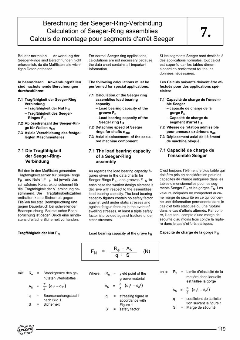
119
7.Bei der normalen Anwendung derSeeger-Ringe sind Berechnungen nichterforderlich, da die Maßlisten alle wich-tigen Daten enthalten.
In besonderen Anwendungsfällensind nachstehende Berechnungendurchzuführen:
7.1 Tragfähigkeit der Seeger-RingVerbindung– Tragfähigkeit der Nut FN– Tragfähigkeit des Seeger-
Ringes FR7.2 Ablösedrehzahl der Seeger-Rin-
ge für Wellen nabl7.3 Axiale Verschiebung des festge-
legten Maschinenteiles
7.1 Die Tragfähigkeit der Seeger-Ring-Verbindung
Bei den in den Maßlisten genanntenTragfähigkeitszahlen für Seeger-RingeFR und Nuten F N ist jeweils dasschwächere Konstruktionselement fürdie Tragfähigkeit der V erbindung be-stimmend. Die Tragfähigkeitszahlenenthalten keine Sicherheit gegenFließen bei stat. Beanspruchung undgegen Dauerbruch bei schwellenderBeanspruchung. Bei statischer Bean-spruchung ist gegen Bruch eine minde-stens dreifache Sicherheit vorhanden.
Tragfähigkeit der Nut FN
mit: Re = Streckgrenze des ge-nuteten Werkstoffes
q = Beanspruchungsszahl nach Bild 1
S = Sicherheit
For normal Seeger ring applications,calculations are not necessary becausethe data chart contains all importantInformation.
The following calculations must beperformed for special applications:
7.1 Calculation of the Seeger ringassemblies load bearing capacity– Load bearing capacity of the
groove FN– Load bearing capacity of the
Seeger ring FR7.2 Detaching speed of Seeger
rings for shafts nabl7.3 Axial displacement. of the secu-
red machine component
7.1 The load bearing capacity of a Seeger-Ring assembly
As regards the load bearing capacity fi-gures given in the data charts forSeeger-Rings F R and grooves F N ineach case the weaker design element isdecisive with respect to the assembliesload bearing capacity. The load bearingcapacity figures contain no safety factoragainst yield under static stresses andagainst fatigue fracture in the event ofswelling stresses. At least a triple safetyfactor is provided against fracture understatic stresses.
Load bearing capacity of the grove FN
Where: Re = yield point of the groove material
q = stressing figure in accordance with Figure 1
S = safety factor
Si les segments Seeger sont destinés àdes applications normales, tout calculest superflu car les tables dimen-sionnelles renferment toutes lesdonnées nécessaires.
Les Calculs suivants doivent être ef-fectués pour des applications spé-ciales:
7.1 Capacité de charge de l’ensem-ble Seeger– capacité de charge de la
gorge FN– Capacité de charge du
segment d’arrêt FR7.2 Vitesse de rotation admissible
pour anneaux extérieurs nabl7.3 Déplacement axial de I’élément
de machine bloqué
7.1 Capacité de charge de l’ensemble Seeger
C’est toujours I’élément le plus faible quidoit être pris en considération pour lescapacités de charge indiquées dans lestables dimensionnelles pour les seg-ments Seeger FR et les gorges FN. Lesvaleurs indiquées ne comportent aucu-ne marge de sécurité en ce qui concer-ne une déformation permanente dans lecas d’ef forts statiques ou une rupturedans le cas d’efforts alternés. Par cont-re, il est tenu compte d’une marge desécurité d’au moins trois contre la ruptu-re dans le cas d’efforts statiques.
Capacité de charge de la gorge F N
on a: Re = Limite d’élasticité de lamatière dans laquelle est taillée la gorge
q = coefficient de sollicita-tion suivant la figure 1
S = Marge de sécurité
Berechnung der Seeger-Ring-VerbindungCalculation of Seeger-Ring assemblies
Calculs de montage pour segments d‘arrêt Seeger
FN = (N)Re · ANq · S
AN = π4
(d12 – d22) AN =π4
(d12 – d22)AN = π
4(d12 – d22)
120
7.
Die Werte in den Maßlisten gelten für:
Re = 200 N/mm2 (bezogen auf ge-nuteten Werkstoff)
q = 1,2 bei n/t = 3S = 1
Umrechnung:Hat der eingesetzte W erkstoff eine an-dere Streckgrenze Re gilt:
Bei abweichender Nuttiefe t’ oder Nut-fläche AN’ aufgrund von anderem Nut-durchmesser und/oder Nenndurchmes-ser d1 bzw. von einem Kantenbruch desNutrandes gilt:
Bei Bundlängenverhältnissen n/t ≤ 3sind die W erte F N mit dem Korrek-turfaktor aus Diagramm Bild 2 zu multi-plizieren.
The values in the data charts apply to:
Re = 200 N/mm2 (referred to groo-ved material)
q = 1,2 with n/t = 3s = 1
Conversion:If the material used has a different yieldRe the following applies:
If the groove depth t’ or groove area AN’deviates due to a dif ferent groove dia-meter and/or nominal diameter d1 or dueto groove edge rounding, the followingapplies:
In the event of shoulder length ratios n/t≤ 3, the values FN must be multiplied bythe compensation factor given in thediagram in Figure 2.
Les valeurs des tables dimensionnellessont valables pour:Re = 200 N/mm2 (en se référant à la
matière où est taillée la gorge)q = 1,2 avec n/t = 3S = 1
Conversion:Si la matière utilisée a une autre limiteélastique Re on a:
Si la profondeur de gorge t’ ou la surfa-ce de gorge AN’ sont différentes à cau-se d’un autre diamètre de gorge et/oud’un autre diamètre nominal d, ou en-core à cause d’un chanfrein au bord dela gorge, on a:
Dans le cas de rapports n/t ≤ 3, les va-leurs FN doivent être multipliées par lefacteur de correction p du diagrammede la figure 2.
Berechnung der Seeger-Ring-VerbindungCalculation of Seeger-Ring assemblies
Calculs de montage pour segments d‘arrêt Seeger
Bild 1Figure 1Figure 1
Bild 2Figure 2Figure 2
FN� = FN (N)Re�
200
FN� = FN = FN (N)t�t
AN�
AN

FRg = (N)� · K(g + 0,05) · S
FR = (N)� · Kh · S
121
7.Beispiel:
Gesucht:Tragfähigkeit der Nut des Seeger-Ringes A 20 bei Werkstoff St 50 (Re’ = 270 N/mm2) Bundlängen-Verhältnis n/t = 2
FN aus Maßliste 10 = 5,0 kNp aus Bild 2 = 0,65FN’ = 4,4 kN (ohne Sicherheit)
Tragfähigkeit des Seeger-Ringes FRund FRg
Man unterscheidet zwei Belastungsfälle:
Example:
Sought:load bearing capacity of the groove ofSeeger ring A 20 consisting of materialSt 50 (Re’ = 270 N/mm2) shoulder lengthratio n/t = 2
FN from data chart 10 = 5,0 kNp from figure 2 = 0,65FN’ = 4,4 kN (no safety factor)
Load bearing capacity FR and FRg ofthe Seeger ring
Two load cases are distinguished:
Exemple:
Résultat cherché:Capacité de charge de la gorge du segment Seeger A20 avec la matière St50 (Re’ = 270 N/mm2), rapport n/t = 2
FN indiqué dans la table dimensionnel-le 10 = 5,0 kNp dans la figure 2 = 0,65FN’ = 4,4 kN (sans marge de sécurité)
Capacité de charge du Segmentd'arrêt Seeger FR et FRg
On distingue deux cas:
Berechnung der Seeger-Ring-VerbindungCalculation of Seeger-Ring assemblies
Calculs de montage pour segments d‘arrêt Seeger
FN� = FN pRe�
200FN� = FN p
Re�
200
FN� = FN pRe�
200
Scharfkantige Anlagesharp-edged faceAppui a angle vif
Anlage mit Kantenabstand (Rundung, Fase) gFace with edged spacing (radiased or chamfered) g
Appui avec distance entre bords (arrondi, chanfrein) g
Bild 3Figure 3Figure 3
Bild 4Figure 4Figure 4

122
7.
Average eccentricity of shaftrings
Average eccentricity of borerings,
of shaft rings,
of bore rings,
Sharp-edged face, Figure 3
Const.Sharp-edged face,Figure 3 if d1 ≥ 150 mm,
See data charts
Natural logarithm
Moyenne d'excentricité pour segments extérieurs
Moyenne d'excentricité pour segments intérieurs
Dans le cas de segments extérieurs
Dans le cas de segments intérieurs
Appui à angles vifs, figure 3,
Appui à angles vifs, figure 3, si d1 ≥ 150 mm
Voir tables dimensionnelles
Logarithme naturel
bm = b - z
z = 0,25 • b Mittelwert der Exzentritzitätbei Wellenringen
z = 0,3 • b Mittelwert der Exzentrizität bei Bohrungsringen,
y = d2 bei Wellenringen,
y = d2 - 2 bm bei Bohrungsringen,
h = 0,3 + 0,002 d1 scharfkantige Anlage Bild 3
h = 0,6 = Konst. scharfkantige Anlage Bild 3, wenn d1 ≥ 150 mm
g = siehe Maßlisten
ln = Natürlicher Logarithmus
( )K = π · E · s 3In 1 + 2 b m [N · mm]
6 y
� = f h
Mit / Where / On a:
Bild 5 : umgestülpter Seeger-RingFigure 5: dished Seeger ringFigure 5: Segment d'arrêt Seeger gauchi
Berechnung der Seeger-Ring-VerbindungCalculation of Seeger-Ring assemblies
Calculs de montage pour segments d‘arrêt Seeger
123
7.
The values in the dats charts apply to:Seeger-Ring material with a modulus ofelasticity = 210 kN/mm2
FR = load bearing capacity withsharp-cornered abutment
FRg = load bearing capacity witha corner distance g
Conversion:When using a dif ferent material for aSeeger-Ring with a different modulus ofelasticity E', the following applies:
Les valeurs indiquées dans les tablesdimensionnelles sont valables pour:Matière du segment d'arrêt Seeger,module d'élasticité = 210 kN/mm2
FR = Capacité de charge en cas d'appui à angles vifs
FRG = Capacité de charge en cas de distance entre bords g
Conversion:En cas d'utilisation d'une autre matièreayant un autre module d'élasticité E'pour le segment d'arrêt Seeger, on a:
Die Werte in den Maßlisten gelten für:Werkstoff des Seeger-Ringes E-Modul= 210 kN/mm2
FR = Tragfähigkeit bei scharfkantigerAnlage
FRg = Tragfähigkeit bei Kantenab-stand g
Umrechnung:Bei Einsatz eines anderen W erkstoffesfür den Seeger-Ring mit anderem E-Modul E’ gilt:
Bild 6: Zulässige Umstülpwinkel der Seeger-Ringe
Figure 6: Permissible dishing angle of Seeger-Rings
Figure 6: Angle de gauchissement admissible pour les segments d'arrêt Seeger
Beispiel:Gesucht ist die Tragfähigkeit desSeeger-Ringes J 22 aus dem WerkstoffBronze CuSn 8 mit einem Elastizitäts-modul von E’ = 115 N/mm2 bei scharf-kantiger Anlage.
Example:The load bearing capacity of Seeger-Ring J 22 consisting of the materialbronze CuSn 8 with a modulus of ela-sticity E' = 115 N/mm2 and for sharp-ed-ged abutment is to be calculated.
Exemple:On cherche la capacité de charge dusegment d'arrêt Seeger J 22 en bronzeCuSn 8 ayant un module d'élasticité E'= 115 N/mm2 en cas d'appui à anglesvifs.
FR� = FRE�
(kN)210 FRg� = FRg
E�(kN)
210
FR� = FR E�
FR aus Maßliste 11 = 8,0 kN / from data chart 1 1 = 8,0 kN / de la table dimensionnelle 1 1 = 8,0 kN210
= 8,0 115210
FR� = 4,38 kN (ohne Sicherheit / no safety factor / sans marge de sécurité)
Wenn die vorhandene Fase, Rundungoder der Kantenabschstand g’ von denin den Maßlisten genannten W erten gabweicht, gilt:
If the existing chamfer , rounded corneror corner distance g' deviates from thevalues g in the data chart, the followingapplies:
Si le chanfrein, l'arrondi ou la distanceentre bords g' diffèrent des valeurs indi-quées dans les tables dimensionnelles,on a:
FRg� = FRgg
(N)g�
Berechnung der Seeger-Ring-VerbindungCalculation of Seeger-Ring assemblies
Calculs de montage pour segments d‘arrêt Seeger
Achtung:Wenn F Rg’ bei kleinen W erten von g’größer ist als FR' gilt FR!
Important:If, at low g' values, the value FRg' is grea-ter than FR' then FR applies!
Attention:Si FRg’ est supérieur à F R dans le casde valeurs g' de faible importance, onprendra FR pour référence.
124
7.Beispiel:Gesucht ist die Tragfähigkeit desSeeger-Ringes A 40 bei einer Fase desandrückenden Maschinenteiles von g’=1,0 mm.
Example: The load bearing capacity of Seegerring A 40 is to be calculated with a cham-fer on the located machine componentof g' = 1.0 mm.
Exemple: Quelle est la capacité de charge du seg-ment d'arrêt Seeger A 40 lorsqueI'élément de machine exerçant la pres-sion comporte un chanfrein g' = 1.0 mrn.
Berechnung der Seeger-Ring-VerbindungCalculation of Seeger-Ring assemblies
Calculs de montage pour segments d‘arrêt Seeger
FRg’ = FRgg
FRg aus Maßliste 10 = 9,5 kN / from data chart 10 = 9,5 kN / de la table dimensionnelle 10 = 9,5 kN)g’
FRg’ = 9,5 2
g aus Maßliste 10 = 2,0 mm / from data chart 10 = 2,0 mm / de la table dimensionnelle 10 = 2,0 mm)1
FRg’ = 19,0 kN (ohne Sicherheit / no safety factor / sans marge de sécurité)
Kantenabstände, die die Tragfähigkeitdes Ringes reduzieren, können sichauch durch größere Dif ferenzen zwi-schen d1 und d1’ (Bild 7) ergeben.
Corner distances, which reduce thering's load bearing capacity , may alsoresult from large-scale dif ferences bet-ween d1 and d1' (Figure 7).
Les distances entre bords qui réduisentla capacité de charge du segment peu-vent également résulter de dif férencesimposantes entre d1 et d1' (figure 7).
Beispiel:Prüfung der Tragfähigkeit einesSeeger-Ringes A 40 bei Anwendunggemäß Bild 7. Der gegenüber d 1 ver-kleinerte Durchmesser soll die Mon-tage des Ringes und die Demontagedes Maschinenteiles erleichtern.
Bild 7: Hebelarm h durch verkleinerten Bunddurchmesser
Figure 7: lever arm h due to a reduced shoulder diameter
Figure 7: Bras de levier h résultant d'une diminution du diamètre de collet
Bild 8: Nut mit Kantenbruch h
Figure 8: Groove with round edge h
Figure 8: Gorge chanfreinée
Example:Testing the load bearing capacity of aSeeger-Ring A 40 for applications inaccordance with Figure 7. The diame-ter reduced in comparison with d 1 isaimed at facilitating ring assembly anddismantling of the machine component.
Exemple: Contrôle de la capacité de charge d'unsegment d'arrêt Seeger A 40 selonfigure 7. Le diamètre réduit par rapportà d1 a été prévu de façon à faciliter lemontage du segment et le démontagede I'élément de machine.
FRg’ = FRgg d1 = 40,0 mmg’ d1’ = 39,4 mm
= 9,5 2
g’ = 1/2 (d1 – d1’) = 0,3 mm0,3
FRg’ = 63,3 kN FRg = 9,5 kNFR = 51,0 kN
Da FRg’ größer ist als FR, gilt FR als ma-ximale Tragfähigkeit des Ringes, d. h.der Kantenabstand resultierend aus d 1– d1’ wirkt sich nicht tragfähigkeitsredu-zierend aus.
Since FRg' is greater than F R, then F Rapplies as the ring's maximum load bea-ring capacity, i.e. the corner distance re-sulting from d1 – d1' does not reduce theload bearing capacity.
Etant donné que FRg’ est supérieur à FRla valeur F R est la capacité de chargemaximale du segment, c.à.d. que la dis-tance entre bords d1 – d1’ n'entraîne pasune baisse de la capacité de charge.
125
7.Wenn die vorhandenen Kräfte bei zugroßen Hebelarmen g nicht aufgenom-men werden können, muß durch Zwi-schenlegen einer Seeger-Stützscheibedie scharfkantige Anlage geschaf fenwerden (Bild 9).
If the existing forces cannot be absor-bed because of excessive lever arms g,a sharp-edge abutment must be createdby inserting a Seeger support washer(Figure 9).
Si les efforts exercés ne peuvent pas être absorbés parce que les bras de le-vier g sont trop importants, il faut réali-ser un appui à angles vifs en intercalantune rondelle d'appui Seeger (figure 9).
Berechnung der Seeger-Ring-VerbindungCalculation of Seeger-Ring assemblies
Calculs de montage pour segments d‘arrêt Seeger
Bild 9: Seeger-Stützscheibe zwischen Seeger-Ring und Maschinenteil
Figure 9: Seeger support washer between Seeger-Ring and machine component
Figure 9: Rondelle d'appui Seeger entre le segment d'arrêt Seeger et I'élément de machine
Tragfähigkeit von Runddrahtspreng-ringen DIN 7993:
In den Maßlisten werden keine Angabenüber die Tragfähigkeit gemacht.
Wenn die Ringe überdeckt zum Einsatzkommen (Bild 10) ist die Tragfähigkeitder Verbindung nur abhängig von derFestigkeit der Werkstoffe von Welle undGehäuse und unabhängig von demRing selbst. Bei dem überdecktenEinbau ist die aus der Axialkraft resul-tierende Radialkomponente zu beach-ten.
Load bearing capacity of circularwire circlips to DIN 7993:
No load bearing capacity information isgiven in the data charts.
If overlapping rings are used (Figure10), the load bearing capacity of the as-sembly depends only on the strength ofthe shaft and housing materials and isindependent of the ring itself. When in-stalling overlapping rings, pay attentionto the radial component resulting fromthe axial force.
Capacité de charge des joncsd'arrêt DIN 7993:
Aucune indication n'est fournie sur la ca-pacité de charge dans les tables di-mensionnelles.
Si les joncs sont noyés (figure 10), la ca-pacité de charge du montage ne dépendque de la résistance des matières uti-lisées pour l'axe et la bague et ne dé-pend pas du jonc proprement dit. En casde montage noyé, il faut tenir compte dela composante radiale résultant de l'ef-fort axial.
Bild 10: Runddrahtsprengring DIN 7993 in überdecktem Einbau
Figure 10: Overlapping circular wire circlip to DIN 7993
Figure 10: Jonc d'arrêt DIN 7993 noyé
Die Tragfähigkeit der Nut wird berech-net mit:
The groove's load bearing capacity iscalculated as follows:
La capacité de charge de la gorge estcalculée suivant la formule suivante:
FN = Re · AN1,2 · S
Die Sicherheit S sollte mindestens 1,25betragen. Für die Nutfläche AN = �/4(d12 – d22) ist in der Regel die kleinereNutfläche der Welle einzusetzen.
The safety factor S should be at least1,25. As a rule, the smaller groove areaof the shaft must be calculated for thegroove area AN = �/4 (d12 – d22).
La marge de sécurité S doit être d'aumoins 1,25. Pour la surface de gorgeAN = �/4 (d12 – d22) il convient d'utili-ser en règle générale la plus petitesurface de gorge de l'arbre.

126
√
7.7.2 Detaching speed nabl
of shaft rings7.2 Vitesse de rotation
maximum admissible nabl des segments d'arrêtextérieurs
Berechnung der Seeger-Ring-VerbindungCalculation of Seeger-Ring assemblies
Calculs de montage pour segments d‘arrêt Seeger
7.2 Ablösedrehzahl nabl vonWellenringen
nabl = 37200000 · b d 2 – d3 (1/min. / V/mn / trs/mn)(d2 + b)2 d3 + b
Die Gleichung gilt für folgende Ringe:Seeger-Ringe DIN 471Seeger-Sprengringe DIN 5417Seeger-Sprengringe SW
Bei folgenden Ringen ist das Ergebnismit 0,95 zu multiplizieren:Seeger-K-RingeSeeger-V-RingeSeeger-L-Ringe
Die Ablösedrehzahl ist die Drehzahl, beider sich der Ring aufgrund der auf ihneinwirkenden Fliehkräfte öffnet und sichvon seinem Sitz in der Nut zu lösen be-ginnt. Ein Abspringen ist erst nach einerweiteren Drehzahlsteigerung um 50%zu erwarten. Die in den Maßlisten allerWellenringe genannten Werte gelten fürStahlringe, bei Ringen aus Bronze sinddie Zahlen mit 0,7 zu multiplizieren.
Liegt die vorhandene Drehzahl oberhalbder Ablösedrehzahl, ist eine Rückspra-che mit der Technischen Beratung vonSeeger-Orbis zu empfehlen. Durchüberdeckten Einbau mit Hilfe einerAusdrehung (Bild 10) können zentrischbegrenzte Ringe wie Seeger-K-Ringe,Seeger-V-Ringe und Seeger-Spreng-ringe durch Formschluß in der Nut ge-halten und bei Drehzahlen verwendetwerden, die oberhalb der Ablösedreh-zahl liegen (s. auch Abschnitt „Konstruk-tive Einzelheiten“).
This equation applies to the followingrings:Seeger-Rings DIN 471Seeger circlips DIN 5417Seeger circlips SW
For the following rings, the result mustbe multiplied by 0.95: Seeger-K-Rings Seeger-V-RingsSeeger-L-Rings
The detaching speed is the speed atwhich the ring opens due to the centri-fugal forces acting on it and begins toseparate from its fit in the groove. If can-not be expected to spring of f until thespeed is further increased by 50%. Thevalues given in the data charts of allshaft rings apply to steel rings and, forbronze rings, the figures must be multi-plied by 0,7.
If the speed involved is higher than thedetaching speed, please consult theSeeger-Orbis technical advisory servi-ce. By overlapped assembly with the aidof a turned recessed (Figure 10), cen-trically restricted rings such as Seeger-K-Rings, Seeger-V -Rings and Seegercirclips can be held in the groove by aform fit and can be used at speeds abo-ve the detaching speed (see alsoSection "Design details").
Cette équation est valable pour les seg-ments suivants:Segments d'arrêt Seeger DIN 471Anneaux expansifs Seeger DIN 5417Anneaux expansifs Seeger type SW
Pour les segments d'arrêt suivants, lerésultat doit être multiplié par 0,95:Segments d'arrêt Seeger type KSegments d'arrêt type VSegments d'arrêt type L
La vitesse de rotation maximum est lavitesse à laquelle les segments d'arrêts'ouvrent sous l'action des forces cen-trifuges appliquées et commencent à sedégager de leur gorge. Il faut s'attendreà ce que le segment d'arrêt sorte si lavitesse augmente encore de 50%. Lesvaleurs indiquées dans les tables di-mensionnelles sont valables pour dessegments d'arrêt en acier. Pour les seg-ments d'arrêt en bronze, multiplier cesvaleurs par 0,7.
Si la vitesse ef fective est supérieure àla vitesse de rotation maximum admis-sible, consulter les services techniquesde la société Seeger-Orbis. En cas demontage noyé (figure 10), les segmentslimités concentriquement tels les seg-ments d'arrêt Seeger type K, les seg-ments d'arrêt Seeger type V et les an-neaux expansifs Seeger sont maintenusdans la gorge grâce au fait qu'ils épou-sent intégralement la forme de celle-ciet peuvent par la-même être utilisés àdes vitesses de rotation supérieures àla vitesse de rotation maximum admis-sible (voir également le chapitre "Re-commandations de Construction").
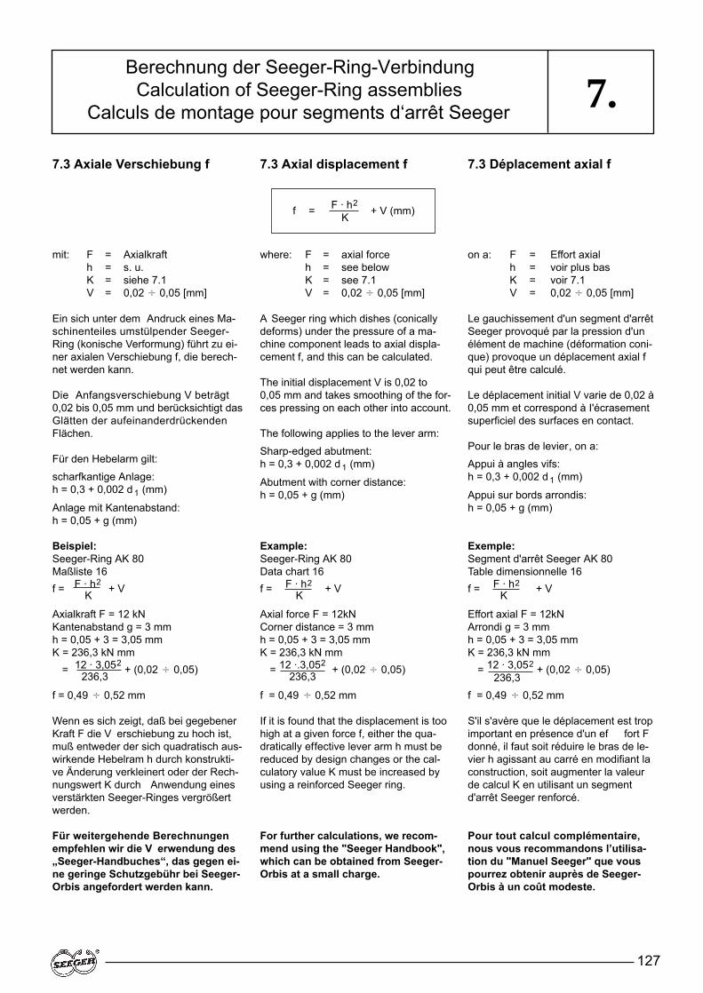
127
7.7.3 Axiale Verschiebung f 7.3 Axial displacement f 7.3 Déplacement axial f
Berechnung der Seeger-Ring-VerbindungCalculation of Seeger-Ring assemblies
Calculs de montage pour segments d‘arrêt Seeger
mit: F = Axialkrafth = s. u.K = siehe 7.1V = 0,02 � 0,05 [mm]
Ein sich unter dem Andruck eines Ma-schinenteiles umstülpender Seeger-Ring (konische Verformung) führt zu ei-ner axialen Verschiebung f, die berech-net werden kann.
Die Anfangsverschiebung V beträgt0,02 bis 0,05 mm und berücksichtigt dasGlätten der aufeinanderdrückendenFlächen.
Für den Hebelarm gilt:
scharfkantige Anlage:h = 0,3 + 0,002 d 1 (mm)
Anlage mit Kantenabstand:h = 0,05 + g (mm)
Beispiel:Seeger-Ring AK 80Maßliste 16f = F · h2
+ VK
Axialkraft F = 12 kNKantenabstand g = 3 mmh = 0,05 + 3 = 3,05 mmK = 236,3 kN mm
= 12 · 3,052+ (0,02 � 0,05)236,3
f = 0,49 � 0,52 mm
Wenn es sich zeigt, daß bei gegebenerKraft F die V erschiebung zu hoch ist,muß entweder der sich quadratisch aus-wirkende Hebelram h durch konstrukti-ve Änderung verkleinert oder der Rech-nungswert K durch Anwendung einesverstärkten Seeger-Ringes vergrößertwerden.
Für weitergehende Berechnungenempfehlen wir die V erwendung des„Seeger-Handbuches“, das gegen ei-ne geringe Schutzgebühr bei Seeger-Orbis angefordert werden kann.
where: F = axial forceh = see belowK = see 7.1V = 0,02 � 0,05 [mm]
A Seeger ring which dishes (conicallydeforms) under the pressure of a ma-chine component leads to axial displa-cement f, and this can be calculated.
The initial displacement V is 0,02 to0,05 mm and takes smoothing of the for-ces pressing on each other into account.
The following applies to the lever arm:
Sharp-edged abutment: h = 0,3 + 0,002 d 1 (mm)
Abutment with corner distance:h = 0,05 + g (mm)
Example: Seeger-Ring AK 80Data chart 16f = F · h2 + VK
Axial force F = 12kNCorner distance = 3 mmh = 0,05 + 3 = 3,05 mmK = 236,3 kN mm
= 12 ·.3,052+ (0,02 � 0,05)236,3
f = 0,49 � 0,52 mm
If it is found that the displacement is toohigh at a given force f, either the qua-dratically effective lever arm h must bereduced by design changes or the cal-culatory value K must be increased byusing a reinforced Seeger ring.
For further calculations, we recom-mend using the "Seeger Handbook",which can be obtained from Seeger-Orbis at a small charge.
on a: F = Effort axialh = voir plus basK = voir 7.1V = 0,02 � 0,05 [mm]
Le gauchissement d'un segment d'arrêtSeeger provoqué par la pression d'unélément de machine (déformation coni-que) provoque un déplacement axial fqui peut être calculé.
Le déplacement initial V varie de 0,02 à0,05 mm et correspond à I'écrasementsuperficiel des surfaces en contact.
Pour le bras de levier, on a:
Appui à angles vifs: h = 0,3 + 0,002 d 1 (mm)
Appui sur bords arrondis: h = 0,05 + g (mm)
Exemple: Segment d'arrêt Seeger AK 80Table dimensionnelle 16f = F · h2 + VK
Effort axial F = 12kNArrondi g = 3 mmh = 0,05 + 3 = 3,05 mmK = 236,3 kN mm
= 12 · 3,052 + (0,02 � 0,05)236,3
f = 0,49 � 0,52 mm
S'il s'avère que le déplacement est tropimportant en présence d'un ef fort Fdonné, il faut soit réduire le bras de le-vier h agissant au carré en modifiant laconstruction, soit augmenter la valeurde calcul K en utilisant un segmentd'arrêt Seeger renforcé.
Pour tout calcul complémentaire,nous vous recommandons l’utilisa-tion du "Manuel Seeger" que vouspourrez obtenir auprès de Seeger-Orbis à un coût modeste.
f = F · h2+ V (mm)K
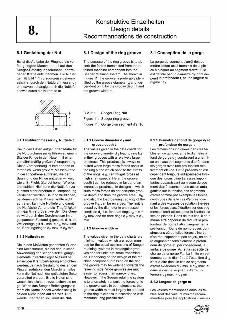
128
8.8.1 Gestaltung der Nut
Es ist die Aufgabe der Ringnut, die vomfestgelegten Maschinenteil auf dasSeeger-Befestigungselement übertra-genen Kräfte aufzunehmen. Die Nut istgemäß Bild 1 1 vorzugsweise gekenn-zeichnet durch den Nutdurchmesser d2und davon abhängig durch die Nuttiefet sowie durch die Nutbreite m.
8.1 Design of the ring groove
The purpose of the ring groove is to ab-sorb the forces transmitted from the re-tained machine component into theSeeger retaining system. As shown inFigure 11, the groove is preferably iden-tified by the groove diameter d2 and, de-pendent on it, by the groove depth t andthe groove width m.
8.1 Conception de la gorge
La gorge du segment d'arrêt doit ad-mettre l'effort axial transmis de la piè-ce à bloquer au segment d'arrêt. Elleest définie par un diamètre d 2 dont dé-pend la profondeur t, et une largeur m(figure 11).
Konstruktive EinzelheitenDesign details
Recommandations de construction
Bild 11: Seeger-Ring-Nut
Figure 11: Seeger ring groove
Figure 11: Gorge d'un segment d'arrêt
8.1.1 Nutdurchmesser d2, Nuttiefe t
Die in den Listen aufgeführten Maße fürdie Nutdurchmesser d2 führen zu einemSitz der Ringe in den Nuten mit einerverhältnismäßig großen V orspannung.Diese Vorspannung ist immer dann er-forderlich, wenn größere Massenkräftein der Ringebene auftreten, die derSpannung der Ringe entgegenwirken,wie z. B. Fliehkräfte bei hohen W ellen-drehzahlen. Hier kann die Nuttiefe t zu-gunsten einer erhöhten V orspannungverkleinert werden. Bei Konstruktionen,bei denen solche Massenkräfte nichtauftreten, kann die Nuttiefe und damitdie Nutfläche AN und die Tragfähigkeitder Nut FN vergrößert werden. Die Gren-ze wird durch den Durchmesser im un-gespannten Zustand d3 gesetzt, d. h. beiWellenringe gilt d 2 min. = d 3 max. undbei Bohrungsringen d2 max. = d3 min.
8.1.2 Nutbreite m
Die in den Maßlisten genannten W ertesind Kleinstmaße, die bei der üblichenAnwendung der Seeger-Befestigungs-elemente in rechteckiger Nut und beieinseitiger Kraftübertragung empfohlenwerden. Je nach Gestaltung des an denRing anzudrückenden Maschinenteileskann die Nut nach der entlasteten Seiteverbreitert werden. Breite Nuten sindwesentlich leichter einzustechen als en-ge. Wenn das Seeger-Befestigungsele-ment die Kräfte jedoch wechselseitig inbeiden Richtungen auf die zwei Nut-wände übertragen soll, muß die Nut-
8.1.1 Groove diameter d2 and groove depth t
The values given in the data charts forthe groove diameter d 2 lead to ring fitsin their grooves with a relatively largeprestress. This prestress is always re-quired when large mass forces occur inthe ring plane which oppose the stressof the rings, e.g. centrifugal forces athigh shaft speeds. Here, the groovedepth t can be reduced in favour of anincreased prestress. In designs in whichsuch mass forces do not occur, the groo-ve depth and thus the groove area ANand also the load bearing capacity of thegroove FN, can be enlarged. The limit isposed by the diameter in unstressedcondition d3, i.e. for shaft rings d2 min =d3 max and for bore rings d 2 max = d 3min.
8.1.2 Groove width m
The values given in the data charts areminimum values which are recommen-ded for the usual applications of Seegerretaining systems in rectangular groo-ves and for unilateral force transmissi-on. Depending on the design of the ma-chine component pressing on the ring,the groove may be widened towards therelieving side. Wide grooves are mucheasier to recess than narrow ones.However, if the Seeger retaining systemis to alternately transmit the forces ontothe groove walls in both directions, thegroove width m must largely be adaptedto the ring thickness in accordance withmanufacturing possibilities.
8.1.1 Diamètre de fond de gorge d2 etprofondeur de gorge t
Les dimensions indiquées dans les ta-bles en ce qui concerne le diamètre àfond de gorge d 2 conduisent à une mi-se en place des segments d'arrêt dansles gorges avec une pré-tension rela-tivement élevée. Cette pré-tension estcependant toujours indispensable lors-que des forces d'inertie assez impor-tantes apparaissant au niveau du seg-ment d'arrêt exercent une action anta-goniste sur la tension des segmentsd'arrêt comme par exemple les forcescentrifuges dans le cas d'arbres tour-nant à des vitesses de rotation élevéeset les forces d'accélération sur des seg-ments d'arrêt utilisés pour la fixation d'a-xes de pistons. Dans de tels cas, il peutmême être opportun de réduire la pro-fondeur de gorge t afin d'augmenter lapré-tension. Dans de nombreuses con-structions où de telles forces d'inertien'entrent cependant pas en jeu, on pour-ra augmenter sensiblement la profon-deur de gorge et, par conséquent, lasurface de gorge AN et la capacité decharge de la gorge F N. La limite en estdonnée par le diamètre à I'état libre d 3c'est-à-dire dans le cas de segmentsd'arrêt extérieurs d 2 min. = d 3 max. etdans le cas de segments d'arrêt in-térieurs d2 max. = d3 min.
8.1.2 Largeur de gorge m
Les valeurs mentionnées dans les ta-bles sont des valeurs minima recom-mandées pour les applications usuelles
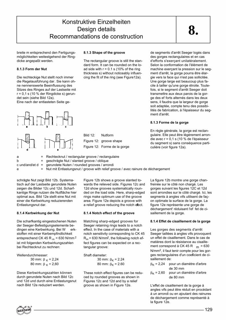
129
8.breite m entsprechend den Fertigungs-möglichkeiten weitestgehend der Ring-dicke angepaßt werden.
8.1.3 Form der Nut
Die rechteckige Nut stellt noch immerdie Regelausführung dar. Sie kann oh-ne nennenswerte Beeinflussung desSitzes des Ringes auf der Lastseite mitr = 0,1 s (10 % der Ringdicke s) gerun-det sein (siehe Bild 12a).Eine nach der entlasteten Seite ge-
8.1.3 Shape of the groove
The rectangular groove is still the stan-dard form. It can be rounded on the lo-ad side with r = 0.1 s (10% of the ringthickness s) without noticeably influen-cing the fit of the ring (see Figure12a).
de segments d'arrêt Seeger logés dansdes gorges rectangulaires et en casd'efforts s'exerçant unilatéralement.Selon la conformation de I'élément demachine exerçant la pression sur le seg-ment d'arrêt, la gorge pourra être élar-gie vers la face qui n'est pas sollicitée.Une gorge large est beaucoup plus fa-cile à tailler qu'une gorge étroite. Toute-fois, si le segment d'arrêt Seeger doittransmettre aux deux parois de la gor-ge des ef forts alternés dans les deuxsens, il faudra que la largeur de gorgesoit adaptée, compte tenu des possibi-lités de fabrication, à I'épaisseur du seg-ment d'arrêt.
8.1.3 Forme de la gorge
En règle générale, la gorge est rectan-gulaire. Elle peut être légèrement arron-die avec r = 0,1 s (10 % de I'épaisseurdu segment s) sans conséquence parti-culière (voir figure 12a).
Konstruktive EinzelheitenDesign details
Recommandations de construction
Bild 12: Nutform
Figure 12: groove shape
Figure 12: Forme de la gorge
schrägte Nut zeigt Bild 12b. Systema-tisch auf der Lastseite gerundete Nutenzeigen die Bilder 12c und 12d. Scharf-kantige Ringe nutzen die Nutfläche hieroptimal aus. Bild 12e stellt eine Nut miteiner die Kerbwirkung reduzierendenEntlastungsnut dar.
8.1.4 Kerbwirkung der Nut
Die scharfkantig eingestochenen Nutender Seeger-Befestigungselemente be-dingen eine Kerbwirkung. Bei W erk-stoffen mit einer Kerbempfindlichkeitentsprechend CK 45 R m = 630 N/mm 2
ist mit folgenden Kerbwirkungszahlenbei Rechtecknut zu rechnen:
Wellendurchmesser:30 mm: � K = 2,2480 mm: � K = 2,60
Diese Kerbwirkungszahlen könnendurch gerundete Nuten nach Bild 12cund 12d und durch eine Entlastungsnutnach Bild 12e reduziert werden.
Figure 12b shows a groove slanted to-wards the relieved side. Figures 12c and12d show grooves systematically roun-ded on the load side. Here, sharp-edgedrings make optimum use of the groovearea. Figure 12e depicts a groove witha relief groove reducing the notch effect.
8.1.4 Notch effect of the groove
Matching sharp-edged grooves forSeeger retaining rings leads to a notcheffect. In the case of materials with anotch sensitivity corresponding to CK 45Rm = 630 N/mm2, the following notch ef-fect figures can be expected on a rec-tangular groove:
Shaft diameter:30 mm: �K = 2.2480 mm: �K = 2.60
These notch effect figures can be redu-ced by rounded grooves as shown inFigures 12c and 12d and by a reliefgroove as shown in Figure 12e.
La figure 12b montre une gorge chan-freinée sur le côté non chargé. Lesgorges suivant les figures 12C et 12dsont arrondies sur le côté chargé. Ici, lessegments à angles vifs utilisent de faç-on optimale la surface de la gorge. Lafigure 12e représente une gorge dedéchargement' réduisant l'ef fet de ci-saillement de la gorge.
8.1.4 Effet de cisaillement de la gorge
Les gorges des segments d'arrêtSeeger taillées à angles vifs provoquentun effet de cisaillement. Dans le cas dematières dont la résistance au cisaille-ment correspond à CK 45 R m = 630N/mm2, il faut tenir compte pour les gor-ges rectangulaires d'un coefficient de ci-saillement de:�K = 2,24 pour un diamètre d'arbre
de 30 mm �K = 2,60 pour un diamètre d'arbre
de 80 mm
L'effet de cisaillement de la gorge àangles vifs peut être réduit en procédantà un arrondi ou en ajoutant des rainuresde déchargement comme représenté àla figure 12e.
a = Rechtecknut / rectangular groove / rectangulaireb = geschrägte Nut / slanted groove / obliquec und/and/et d = gerundete Nuten / rounded grooves / arrondi e = Nut mit Entlastungsnut / groove with relief groove / avec rainure de déchargement
130
8.8.2 Ausgleich von axialem
Spiel
Wie in Abschnitt 4, Gruppe 4, ausgeführtwurde, ist es mit Hilfe von normalenebenen Seeger-Befestigungselemen-ten nicht möglich, ein Maschinenteil axi-al spielfrei einzubauen. Auf den elasti-schen Spielausgleich mit Hilfe der Ringeder Gruppe 4 ist hingewiesen worden.Nicht in allen Konstruktionen ist der ela-stische Ausgleich, d. h. das Federn derRinge, zulässig. Dann wäre die V er-wendung von Seeger-Keilringen, sieheSeite 78/79, möglich, die eine spielfreieFestlegung des anliegenden Maschi-nenteiles erlauben. Eine stufenweisestarre Reduzierung des Spieles istdurch Anwendung von Seeger-Befesti-gungselementen in Auswahldickenmöglich. Die Stufung und die Dicken-toleranz der meist geschlif fenen Ringeliegt zwischen 0.025 mm und 0.05 mm.Auch Stützscheiben können mit gestuf-ten Dicken hergestellt werden. KleinereDicken-Toleranzen sowie die Fest-legung der kleinsten und größten Dickeist mit Seeger-Orbis abzustimmen.
8.3 Radial formschlüssig festgelegte Seeger-Befestigungselemente
Die Seeger-Ring-V erbindung ist, axialbetrachtet, formschlüssig. Radial sitztder elastische Ring jedoch nur kraft-schlüssig in der Nut. Bei großenAxialkräften und hohen Anforderungenan die Sicherheit kann eine radial form-schlüssige Halterung der Ringe in derNut von Vorteil sein:
– Das Herausarbeiten aus der Nut istunmöglich.
– Verwendung tieferer Nuten, da aufVorspannung verzichtet werdenkann und damit
– größere Tragfähigkeit der Nut– runde Anlage in der Nut sowie– Beseitigung der Drehzahlabhängig-
keit der Wellenringe.
8.2 Compensating axial play
As explained in Section 4, group 4, it isnot possible using normal, flat Seegerretaining systems to assemble machinecomponents without axial play. Attentionhas been drawn to elastic compensati-on of play with the aid of rings in group4. Axial compensation, i.e. a springingeffect of the rings, is not permissible inall designs. In this case, it would be pos-sible to use Seeger bevelled rings (seepage 78/79) which permit play-free re-taining of the machine component. Theuse of selected thicknesses of Seegerretaining systems is possible to rigidlyreduce play in steps. These mostlyground rings are available in gradua-tions and thickness tolerances of bet-ween 0.025 mm and 0.05 mm. Supportwashers can also be manufactured withgraduated thicknesses. Seeger-Orbisshould be consulted before defining thelargest and smallest thicknesses.
8.3 Positive radial retentionof Seeger retaining systems
Viewed axially, the Seeger ring joint is apositive one. However, radially, the elas-tic ring is held in the groove only by itsown tension. Positive radial retention ofrings in the groove may be advanta-geous in the event of high axial forcesand when placing high demands on sa-fety, namely:
– The ring cannot work its way out ofthe groove.
– Use of deeper grooves means thatthere is no need for prestress andthus
– the groove has a greater load bea-ring capacity,
– circular contact is provided in thegroove and
– the speed dependency of the shaftrings is eliminated.
8.2 Compensation du jeu axial
Comme mentionné au chapitre 4, grou-pe 4, un montage sans jeu axial ne peutêtre obtenu à l'aide de segments d'arrêtstandards Seeger . Ceci est possibleavec les segments d'arrêt Seeger dugroupe 4. Toutefois, dans certains cas,une compensation élastique utilisant lespropriétés élastiques des segments nepeut être retenue. Il serait possible dansce cas d'utiliser des segments chan-freinés Seeger (voir page 78/79) quipermettent d'immobiliser I'élément demachine sans jeu. Une réduction pro-gressive du jeu peut être obtenue en uti-lisant des éléments de fixation Seegerà épaisseur variable. L'échelonnementet la tolérance d’épaisseur oscillent ent-re 0,025 mm et 0,05 mm pour la plupartdes segments d'arrêt rectifiés. Les ron-delles d'appui peuvent également êtrefabriquées dans des épaisseurs éche-lonnées. Avant de définir les épaisseursmaximum et minimum, il est préférablede consulter Seeger-Orbis.
8.3 Conception avecSegment d'arrêt Seegerfixé radialement
Axialement, une fixation avec un seg-ment d'arrêt Seeger est optimale; ra-dialement, le segment ne tient que parserrage dans la gorge. Dans le cas decharges axiales élevées et en vue d'ob-tenir une sécurité maximale, on peutenvisager un montage noyé du seg-ment. Les avantages d'un tel montagesont importants:
– Le segment ne peut pas sortir de la gorge.
– La gorge peut être plus profonde carune pré-tension est superflue.
– La capacité de charge de la gorgepeut donc être augmentée.
– La surface de contact est circulairedans la gorge.
– La vitesse de rotation n'est plus li-mitée pour les segments extérieurs.
Konstruktive EinzelheitenDesign details
Recommandations de construction

131
8.
Bild 13 zeigt links die Überdeckung ei-nes Seeger-Ringes und rechts einesRunddrahtringes. Letzterer kann auchanstelle der vierteilkreisförmigen Aus-nehmung mit einer Fase überdeckt wer-den. V oraussetzung für eine Über-deckung ist eine weitestgehend zentri-sche Gestaltung der Ringe. Sie ist beiallen Sprengringen, den Seeger-V -Ringen und den K-Ringen gegeben. Beiden Seeger-Ringen DIN 471/472 giltdies nur für die Ausführungen gemäßden Seiten 22 – 41 Bild links.Die Überdeckung des montierten Rin-ges gemäß Bild 13 ist nur möglich, wenndas Maschinenteil vor der Montagezurückgenommen und später wiederangedrückt werden kann, eine V oraus-setzung, die nicht immer erfüllt ist.Das Seeger-Handbuch gibt weiterge-hende Hinweise auf konstruktive Einzel-heiten der Seeger-Ring-Verbindung.
On the left, Figure 13 shows overlappingof a Seeger ring and on the right, of acircular wire ring. The latter can also beoverlapped with a chamfer instead ofthe quarter circle-shaped recess. Moreor less a centrical design of the rings isa precondition for overlapping. This isensured by all circlips, by the Seeger Vrings and by the K rings. In the case ofSeeger-Rings to DIN 471/472, this ap-plies only to the versions shown onPages 22 – 41, left Illustration. Over-lapping of the fitted ring as shown inFigure 13 is only possible when the ma-chine component can be pulled back be-fore assembly and pressed on again la-ter, a precondition which is not alwaysfulfilled.
The Seeger Handbook gives further in-depth Information on design details ofSeeger-Ring assemblies.
La figure 13 montre le montage noyéd'un segment d'arrêt Seeger à gaucheet d'un jonc d'arrêt à droite. Pour ce der-nier, un chanfrein est possible au lieu deI'évidement en quart de cercle. Pour en-visager un montage noyé, il faut sélec-tionner un segment dont l'encombre-ment est concentrique. Cela sera doncpossible avec tous les anneaux expan-sifs, les anneaux Seeger type V et lesanneaux Seeger type K. Pour les an-neaux standards DIN 471/472, seulescertaines exécutions (voir pages 22 –41, figures de gauche) peuvent être re-tenues.D'autre part, le montage noyé repré-senté sur la figure 13 ne peut être re-tenu que si I'élément à bloquer peut êt-re écarté et remis en place ensuite, con-dition qui n'est pas toujours remplie. Lemanuel Seeger fournit d'autres recom-mandations de conception pour le mon-tage des anneaux Seeger.
Konstruktive EinzelheitenDesign details
Recommandations de construction
Bild 13: Überdeckung eines Seeger-Ringes (links) und eines Runddrahtsprengringes (rechts)
Figure 13: Overlapping of a Seeger ring (left) and a circular wire circlip (right)
Figure 13. Montage noyé d'un segment d'arrêt Seeger (à gauche) et d'un jonc d'arrêt (à droite)
132
9.Seeger-Befestigungselemente könnenihre Funktion nur erfüllen, wenn siesachgemäß montiert werden. Bei derMontage wird der Ring meist höher be-ansprucht als im späteren Betrieb. Un-sachgemäße Montage führt zu Schädenam Ring und/oder an der Nut.
Axialmontierbare Seeger-Ringe
Diese Ringe sind mit Montagelöchernausgestattet und werden meist mit spe-ziellen Zangen montiert bzw . demon-tiert. Hierbei ist wichtig, für jeden ein-zelnen Ring die passende Zange zu ver-wenden. In den Maßlisten ist für jedeRinggröße die geeignete Zange ange-geben; eine Zusammenstellung derZangen ist auf Seite 109 – 110. Die ela-stische V erformung der Seeger-Ringebei der Montage führt zu sehr hohenBiegespannungen, so daß grundsätz-lich gilt:
„Ein Seeger-Ring soll bei der Mon-tage nur so weit gespreizt bzw . zu-sammengespannt werden, wie eszum Überbringen über die Welle oderzum Einführen in die Bohrung not-wendig ist. Welle bzw. Bohrung müs-sen das Nennmaß besitzen.“
Dies ist besonders bei Ringen ausWerkstoffen mit kleiner elastischerDehnung wie Bronze und korrosionsbe-ständigen Stählen zu beachten. Über-beanspruchungen bei der Montageführen zu plastischen Verformungen mitder Folge, daß die Ringe lose oder oh-ne ausreichende V orspannung in derNut sitzen. Bohrungsringe dürfen nur soweit gespannt werden, bis diese geradein die Bohrung eingebracht werden kön-nen. Bei W ellenringen ist immer dieGefahr einer Überspreizung gegeben,da hier keine Begrenzung vorhandenist. Um Überspreizungen zu vermeiden,sollten Montagegeräte mit Begrenzungverwendet werden. Da die starren Greif-ringe gegen eine Überspreizung beson-ders gefährdet sind, sind diese Zangengrundsätzlich mit Begrenzungsschrau-ben ausgerüstet.Der sicherste Schutz gegen Überbean-spruchung ist die Montage mittelsKonen (Bild 14).
Seeger retaining systems can only fulfilltheir function if they are assembled per-fectly. During assembly, the ring is most-ly subjected to higher stresses than du-ring later operation. Improper assemblydamages the ring and/or the groove.
Axially-mountable Seeger-Rings
These rings are equipped with assemb-ly holes and are mostly fitted and dis-mantled using special pliers. It is impor-tant to use the plier suitable for eachsingle ring. This is given for each ring si-ze in the data charts; a list of the pliersis given on pages 109– 110. Elastic de-formation of Seeger rings during as-sembly leads to very high bending stres-ses and so the following always applies:
"During assembly , a Seeger-Ringshould be expanded or closed onlyto the extent necessary to pass overthe shaft or into the bore. The shaftand bore must be of the same nomi-nal diameter as the ring".
This rule applies particularly to rings ma-de of materials with lower elastic yieldsuch as bronze and stainless steel.Overstressing during assembly leads toplastic deformations with the result thatrings fit loosely or without adequate pre-stress in the groove. Extreme over-stressing of bore rings is not possiblebecause these can only be expanded upto contact of the ring ends. Never-theless, bore rings should only be clo-sed just enough to allow insertion intothe bore. On shaft rings, however , the-re is always a risk of overexpansion be-cause they have no limit. Assembly toolswith limits should therefore be used toavoid overexpansion. Since the rigidgrip rings are particularly endangered byoverexpansion, the appropriate pliersare equipped with limiting screws.The most reliable protection againstoverexpansion is assembly using tapers(Figure 14).
Les segments d’arrêt Seeger ne peu-vent remplir leur fonction que s’ils sontconvenablement montés. Un montageincorrect provoque la détérioration dusegment d’arrêt, de la gorge ou encoredes deux parties.
Segments d’arrêt Seeger à montageaxial
Munis de trous de montage, ils sontmontés et démontés le plus souvent àl’aide de pinces spéciales. Il est extrê-mement important de toujours utiliser lapince conçue spécialement pour cha-cun des différents segments d’arrêt (voirpages 109 – 1 10). La déformation éla-stique que subissent les segmentsd’arrêt Seeger en cours de montageprovoque des ef forts de flexion élevés.Il convient donc dans tous les cas d’ob-server la règle suivante:
«Un segment d’arrêt Seeger doit êtreouvert ou comprimé en cours demontage juste ce qu’il est nécessai-re pour permettre son montage surl’arbre ou son introduction dans l’alé-sage. Les arbres et alésages doiventêtre à la cote nominale»
Cela est valable tout particulièrementpour les segments fabriqués dans unematière ayant un faible allongement éla-stique (par exemple le bronze et les a-ciers inoxydables). Toute sollicitationexcessive en cours de montage se tra-duit par des déformations permanenteset a pour conséquence une position flot-tante ou un manque de pré-tension suf-fisante du segment d’arrêt dans la gor-ge. En ce qui concerne les segmentsd’arrêt utilisés pour les alésages, il n’estpas possible d’exercer une sollicitationsupérieure à celle qui correspond àamener les deux extrémités en contact.Cependant, les segments d’arrêt inté-rieurs utilisés pour les alésages ne doi-vent être comprimés que juste ce qu’ilest nécessaire pour les introduire dansl’alésage. Dans le cas des segmentsd’arrêt extérieurs pour arbres, on courttoujours le risque de les écarter de ma-nière excessive car il n’existe pas debutées naturelles.Afin d’éviter une solli-citation excessive en cours de montage,tous les outils de montage devraient êt-re utilisés de préférence avec unebutée. Les colliers d’étranglement rigi-des étant particulièrement fragiles, lespinces doivent toujours être équipées devis de blocage.
Montage von Seeger-SicherungsringenAssembly of Seeger Retaining Rings
Montage des segments d’arrêt Seeger
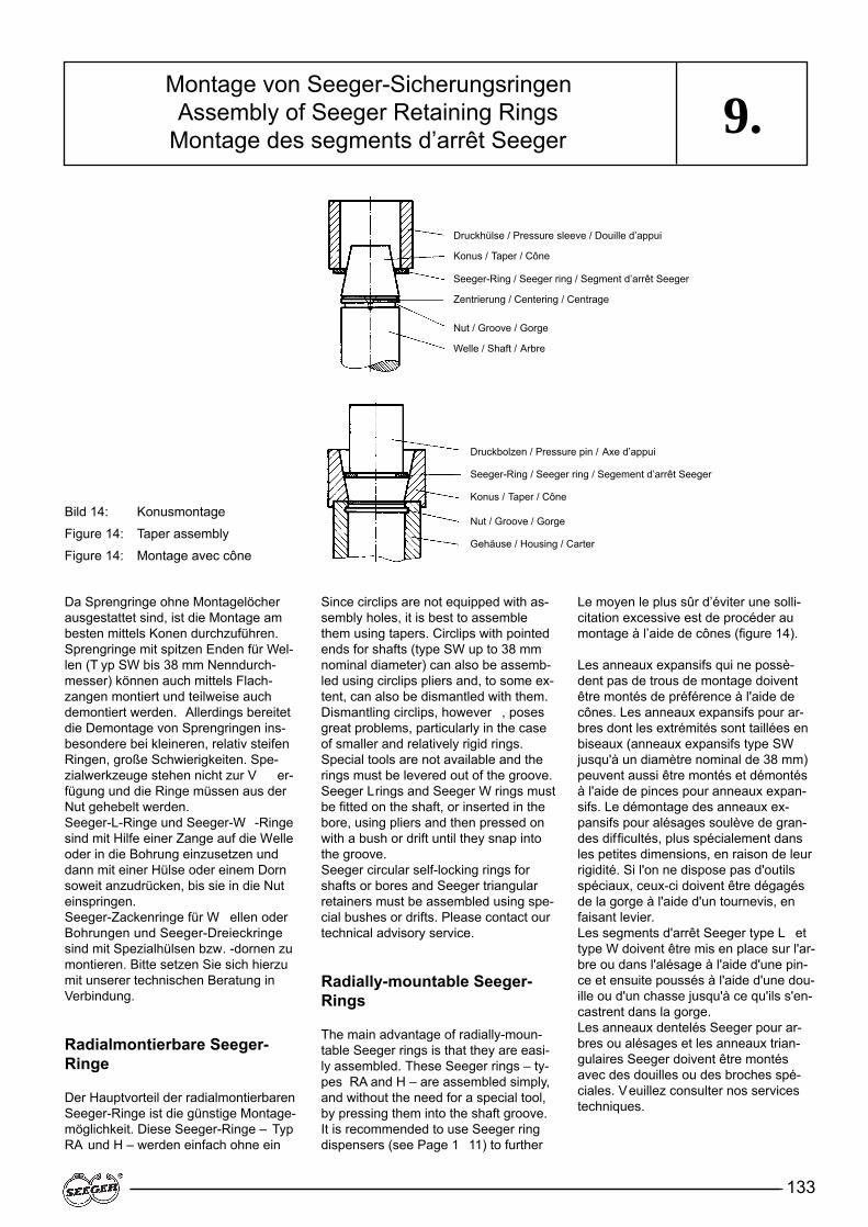
133
9.
Since circlips are not equipped with as-sembly holes, it is best to assemblethem using tapers. Circlips with pointedends for shafts (type SW up to 38 mmnominal diameter) can also be assemb-led using circlips pliers and, to some ex-tent, can also be dismantled with them.Dismantling circlips, however , posesgreat problems, particularly in the caseof smaller and relatively rigid rings.Special tools are not available and therings must be levered out of the groove.Seeger Lrings and Seeger W rings mustbe fitted on the shaft, or inserted in thebore, using pliers and then pressed onwith a bush or drift until they snap intothe groove.Seeger circular self-locking rings forshafts or bores and Seeger triangularretainers must be assembled using spe-cial bushes or drifts. Please contact ourtechnical advisory service.
Radially-mountable Seeger-Rings
The main advantage of radially-moun-table Seeger rings is that they are easi-ly assembled. These Seeger rings – ty-pes RA and H – are assembled simply,and without the need for a special tool,by pressing them into the shaft groove.It is recommended to use Seeger ringdispensers (see Page 1 11) to further
Le moyen le plus sûr d’éviter une solli-citation excessive est de procéder aumontage à l’aide de cônes (figure 14).
Les anneaux expansifs qui ne possè-dent pas de trous de montage doiventêtre montés de préférence à l'aide decônes. Les anneaux expansifs pour ar-bres dont les extrémités sont taillées enbiseaux (anneaux expansifs type SWjusqu'à un diamètre nominal de 38 mm)peuvent aussi être montés et démontésà l'aide de pinces pour anneaux expan-sifs. Le démontage des anneaux ex-pansifs pour alésages soulève de gran-des difficultés, plus spécialement dansles petites dimensions, en raison de leurrigidité. Si l'on ne dispose pas d'outilsspéciaux, ceux-ci doivent être dégagésde la gorge à l'aide d'un tournevis, enfaisant levier.Les segments d'arrêt Seeger type L ettype W doivent être mis en place sur l'ar-bre ou dans l'alésage à l'aide d'une pin-ce et ensuite poussés à l'aide d'une dou-ille ou d'un chasse jusqu'à ce qu'ils s'en-castrent dans la gorge.Les anneaux dentelés Seeger pour ar-bres ou alésages et les anneaux trian-gulaires Seeger doivent être montésavec des douilles ou des broches spé-ciales. Veuillez consulter nos servicestechniques.
Montage von Seeger-SicherungsringenAssembly of Seeger Retaining Rings
Montage des segments d’arrêt Seeger
Da Sprengringe ohne Montagelöcherausgestattet sind, ist die Montage ambesten mittels Konen durchzuführen.Sprengringe mit spitzen Enden für Wel-len (T yp SW bis 38 mm Nenndurch-messer) können auch mittels Flach-zangen montiert und teilweise auchdemontiert werden. Allerdings bereitetdie Demontage von Sprengringen ins-besondere bei kleineren, relativ steifenRingen, große Schwierigkeiten. Spe-zialwerkzeuge stehen nicht zur V er-fügung und die Ringe müssen aus derNut gehebelt werden.Seeger-L-Ringe und Seeger-W -Ringesind mit Hilfe einer Zange auf die Welleoder in die Bohrung einzusetzen unddann mit einer Hülse oder einem Dornsoweit anzudrücken, bis sie in die Nuteinspringen.Seeger-Zackenringe für W ellen oderBohrungen und Seeger-Dreieckringesind mit Spezialhülsen bzw. -dornen zumontieren. Bitte setzen Sie sich hierzumit unserer technischen Beratung inVerbindung.
Radialmontierbare Seeger-Ringe
Der Hauptvorteil der radialmontierbarenSeeger-Ringe ist die günstige Montage-möglichkeit. Diese Seeger-Ringe – TypRA und H – werden einfach ohne ein
Bild 14: Konusmontage
Figure 14: Taper assembly
Figure 14: Montage avec cône
Druckbolzen / Pressure pin / Axe d’appui
Seeger-Ring / Seeger ring / Segement d’arrêt Seeger
Konus / Taper / Cône
Nut / Groove / Gorge
Gehäuse / Housing / Carter
Druckhülse / Pressure sleeve / Douille d’appui
Konus / Taper / Cône
Seeger-Ring / Seeger ring / Segment d’arrêt Seeger
Zentrierung / Centering / Centrage
Nut / Groove / Gorge
Welle / Shaft / Arbre

134
9.Spezialwerkzeug durch Hineindrückenin die Wellennut montiert. Für eine wei-tere V erkürzung von Montagezeitenempfiehlt sich der Einsatz von Seeger-Ringspendern (siehe Seite 1 11). Diesestehen für die Seeger-SicherungsringeDIN 6799 in den Abmessungen 1,2 bis10 mm und die Seeger-Halbmondringein den Abmessungen 3 bis 28 mm zurVerfügung. Für den Einsatz in dieSeeger-Ringspender können die Ringemagaziniert angeliefert werden. Hierzuwerden die Seeger-Sicherungsschei-ben und Seeger-Halbmondringe durcheine Steckleiste bzw. Klebestreifen zu-sammengehalten. Die Entnahme ausdem Spender erfolgt mit einem Greifer ,der gleichzeitig zum Eindrücken in dieNut dient. Die Greifer sind auch in ab-gewinkelter Ausführung lieferbar , sodaß auch eine Montage an schwer zu-gänglichen Stellen möglich ist.
Verpackung
Seeger-Befestigungselemente werdenin den kleineren Durchmesserbereichenin Kartons verpackt und stehen jedochauch als magazinierte Ausführung zurVerfügung. Die größeren Abmess-mengen werden in magazinierter Formin Folie eingeschrumpft.Darüber hinaus stehen verschiedenepatentierte, wiederverwendbare Maga-zinierelemente zur Verfügung.Die V ersand-Verpackung erfolgt inAbstimmung mit dem Kunden inKartons, Gitterboxen, auch Klein-Ladungs-Träger (KLT) oder z.B. auch inGallia-Kartons.
Bitte sprechen Sie auch hierzu schonim Planungsstadium unsere techni-schen Berater an.
shorten assembly times. These areavailable for Seeger retaining rings toDIN 6799 in dimensions of 1,2 to 12 mmand Seeger crescent rings in dimen-sions of 3 to 28 mm. For use in Seegerring dispensers, the rings can be sup-plied in magazines. For this purpose,the Seeger retaining rings and Seegercrescent rings are held together by a railor adhesive tape. They are removedfrom the dispenser using an applicatorwhich simultaneously service to forcethem into the groove. Angled applicatorsare also available for assembly in poor-ly accessible locations.
Packaging
Seeger fastenings of smaller diametersare packed in boxes and are also avai-lable in cassette versions. The larger di-mensions are shrink-wrapped in cas-sette form.In addition various patented re-usablecassettes are available.Dispatch packaging is agreed with thecustomer and is in boxes, wire meshcontainers, light load carrier or e.g.Gallia boxes.
Please consult our technical advi-sory service on this during planning.
Segments d'arrêt Seeger àmontage radial
L'un des principaux avantages des seg-ments d'arrêt Seeger à montage radialest de faciliter les opérations de monta-ge. Ils sont montés en un rien de tempssans outil spécial, il suf fit pour cela deles pousser dans la gorge avec un ob-jet adéquat. Pour réduire encore lestemps de montage, l'emploi de distribu-teurs Seeger (voir page 1 11) est con-seillé. Ces distributeurs sont conçuspour les colliers d'épaulement SeegerDIN 6799 de 1,2 à 12 mm et pour lescroissants Seeger de 3 à 28 mm. Lessegments d'arrêt peuvent être livréspré-empilés pour l'alimentation des dis-tributeurs. Les colliers d'épaulementsont maintenus empilés par une tige etles croissants par une bande adhésive.Ils sont prélevés à l'aide d'une fourchet-te de pose qui sert en même temps àles pousser dans la gorge. Cette four-chette de pose, qui est également livra-ble avec extrémité recourbée, facilite lemontage à des emplacements dif ficile-ment accessibles.
Emballage
Les éléments de fixation Seeger sontemballés dans des cartons pour le do-maine des plus diamètres mais sonttoute fois aussi disponible en sous uneforme mise en magasin. Les quantitésde plus grande ampleur sont frettéssous une forme de mise en magasin.Par ailleurs différents éléments de miseen magasin à usage multiple brevetéssont disponibles .L’emballage pour l’expédition se fait enaccord avec le client en cartons, cais-ses grillagées, petits porteurs de char-ges, ou par ex. aussi en cartons Gallia.
Veuillez vous adresser aussi à ce su-jet dès le stade de planification à osconseillez techniques.
Montage von Seeger-SicherungsringenAssembly of Seeger Retaining Rings
Montage des segments d’arrêt Seeger

135
10.10.1 Härteumrechnungstabelle
für Stahl
Die Umrechnung von Härte auf Festig-keit erfolgt gemäß DIN EN 180 (Ausg2004 – 2002). Die angegebenen Wertesind nur Richtwerte. Die Härten für dieeinzelnen Ausführungsarten und Ab-messungen der Seeger-Ringe werdenin den Maßlisten bzw. den Einführungenzu denselben in Rockwell C (HRC) undVickers (HV) angegeben. Die V ickers-Messung kann bei allen Dicken mit ent-sprechender Belastung vorgenommenwerden. Die Rockwell-Messung ist in-folge der hohen Last von 150 kg nur fürDicken über 1,1 mm anwendbar . Beikleineren Dicken muß auf Vickers über-gegangen werden. Die Umrechnung vonHärten der verschiedenen Prüfver-fahren birgt immer Fehler in sich. Wennirgend möglich, sollte man sie deshalbvermeiden. Ganz ausschalten läßt sichdie Umrechnung jedoch nicht. Dies giltvor allem für die Umrechnung vonHärtewerten in die Festigkeit und um-gekehrt.
10.1 Hardness conversion table for steel
The conversion from hardness to ten-sile strength is according to DIN ISO18265 (edition 2004 – 02). The res-pective values can only be aproximate.In the data charts or their introductions,the hardnessess of the individual versi-ons and dimensions of Seeger rings aregiven in Rockwell C (HRC) and Vickers(HV). Vickers hardness can be measu-red on all thicknesses at an appropriateload. Due to the high load of 150 kg,Rockwell measurement can only be ap-plied to thicknesses in excess of 1,1mm. Vickers hardness must be measu-red on smaller thicknesses. Convertinghardness values always involves inac-curacies. If ever possible, conversionshould be avoided. However , conversi-on cannot always be avoided complete-ly. This applies above all to conversionfrom hardness values to strength and vi-ce versa.
10.1 Table d'équivalence des valeurs de dureté de l'acier
La conversion de la dureté en résis-tance à la traction est suivant la normeDIN ISO 18265 (édition 2004-02). Lesvaleurs sont seulement approximatives.Dans les tables dimensionnelles et l'in-troduction, les duretés des segmentsd'arrêt Seeger de différents types et di-mensions sont indiquées en unitésRockwell C (HRC) et V ickers (HV). Ladétermination de la dureté selon le pro-cédé V ickers convient à toutes lesépaisseurs de segments puisque lacharge appliquée varie suivant I'épais-seur. Par contre, le procédé Rockwelln’est applicable qu'avec des épaisseurssupérieures à 1,1 mm en raison de lacharge élévée de 150 kg qui est appli-quée. Avec une épaisseur inférieure, ilfaut donc avoir recours au procédéVickers. La conversion des valeurs dedureté d'un système à l'autre est tou-jours une source d’erreur qu'il convientd'éviter dans la mesure du possible.Certaines conversions restent inévita-bles. Cela vaut particulièrement pour lesconversions de valeurs de dureté en ré-sistance et vice-versa.
TabellenTables
Tables d’équivalence
ZugfestigkeitTensile strength
Résistance à la traction
N/mm2
VickershärteVickers hardness
Dureté Vickers
(F ≥ 98 N)
Rockwellhärte / Rockwell hardness / Dureté Rockwell
HRC HR 15 N HR 30 N HR 45 N(1471 ± 9 N) (147 ± 1 N) (294 ± 2 N) (441 ± 3 N)
255 80270 85285 90305 95320 100
335 105350 110370 115385 120400 125
415 130430 135450 140465 145480 150
495 155510 160545 170
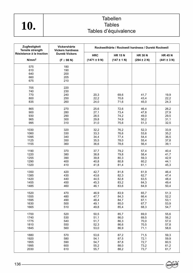
136
10.TabellenTables
Tables d’équivalence
ZugfestigkeitTensile strength
Résistance à la traction
N/mm2
VickershärteVickers hardness
Dureté Vickers
(F ≥ 98 N)
Rockwellhärte / Rockwell hardness / Dureté Rockwell
HRC HR 15 N HR 30 N HR 45 N(1471 ± 9 N) (147 ± 1 N) (294 ± 2 N) (441 ± 3 N)
575 180610 190640 200660 205675 210
705 220740 230770 240 20,3 69,6 41,7 19,9800 250 22,2 70,6 43,4 22,2835 260 24,0 71,6 45,0 24,3
865 270 25,6 72,6 46,4 26,2900 280 27,1 73,4 47,8 27,9930 290 28,5 74,2 49,0 29,5965 300 29,8 74,9 50,2 31,1995 310 31,0 75,6 51,3 32,5
1030 320 32,2 76,2 52,3 33,91060 330 33,3 76,6 53,6 35,21095 340 34,4 77,4 54,4 36,51125 350 35,5 78,0 55,4 37,81155 360 36,6 78,6 56,4 39,1
1190 370 37,7 79,2 57,4 40,41220 380 38,8 79,8 58,4 41,71255 390 39,8 80,3 59,3 42,91290 400 40,8 80,8 60,2 44,11320 410 41,8 81,4 61,1 45,3
1350 420 42,7 81,8 61,9 46,41385 430 43,6 82,3 62,7 47,41420 440 44,5 82,8 63,5 48,41455 450 45,3 83,2 64,3 49,41485 460 46,1 83,6 64,9 50,4
1520 470 46,9 83,9 65,7 51,31555 480 47,7 84,3 66,4 52,21595 490 48,4 84,7 67,1 53,11630 500 49,1 85,0 67,7 53,91665 510 49,8 85,4 68,3 54,7
1700 520 50,5 85,7 69,0 55,61740 530 51,1 86,0 69,5 56,21775 540 51,7 86,3 70,0 57,01810 550 52,3 86,6 70,5 57,81845 560 53,0 86,9 71,1 58,6
1880 570 53,6 87,2 71,5 59,31920 580 54,1 87,5 72,1 59,91955 590 54,7 87,8 72,7 60,51995 600 55,2 88,0 73,2 61,22030 610 55,7 88,2 73,7 61,7
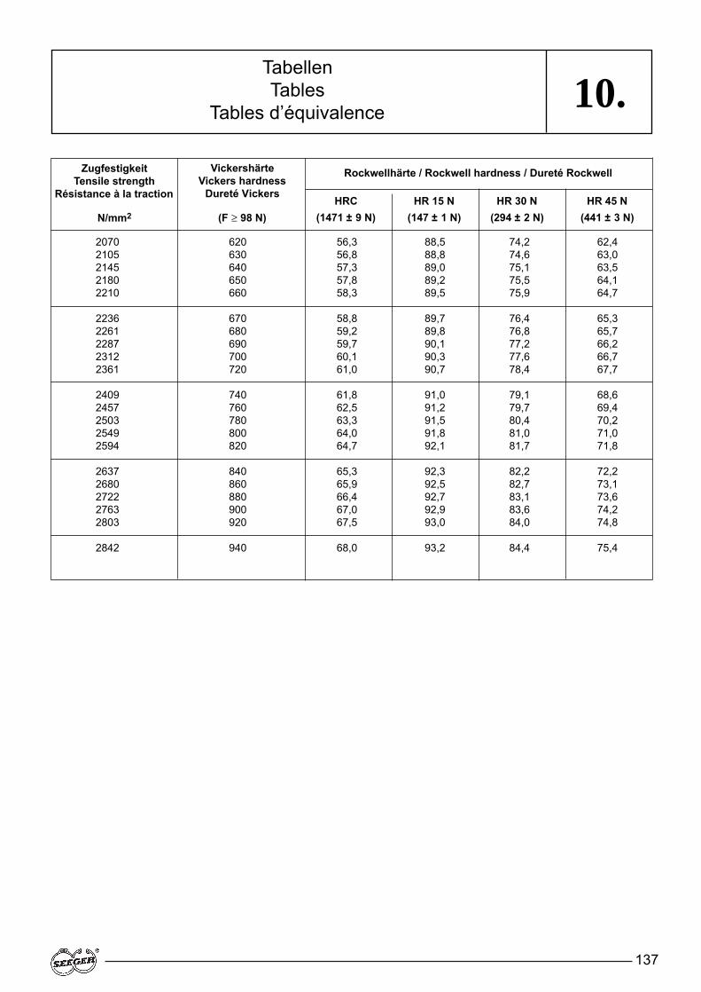
137
10.TabellenTables
Tables d’équivalence
ZugfestigkeitTensile strength
Résistance à la traction
N/mm2
VickershärteVickers hardness
Dureté Vickers
(F ≥ 98 N)
Rockwellhärte / Rockwell hardness / Dureté Rockwell
HRC HR 15 N HR 30 N HR 45 N(1471 ± 9 N) (147 ± 1 N) (294 ± 2 N) (441 ± 3 N)
2070 620 56,3 88,5 74,2 62,42105 630 56,8 88,8 74,6 63,02145 640 57,3 89,0 75,1 63,52180 650 57,8 89,2 75,5 64,12210 660 58,3 89,5 75,9 64,7
2236 670 58,8 89,7 76,4 65,32261 680 59,2 89,8 76,8 65,72287 690 59,7 90,1 77,2 66,22312 700 60,1 90,3 77,6 66,72361 720 61,0 90,7 78,4 67,7
2409 740 61,8 91,0 79,1 68,62457 760 62,5 91,2 79,7 69,42503 780 63,3 91,5 80,4 70,22549 800 64,0 91,8 81,0 71,02594 820 64,7 92,1 81,7 71,8
2637 840 65,3 92,3 82,2 72,22680 860 65,9 92,5 82,7 73,12722 880 66,4 92,7 83,1 73,62763 900 67,0 92,9 83,6 74,22803 920 67,5 93,0 84,0 74,8
2842 940 68,0 93,2 84,4 75,4
138
11.Ablösdrehzahl, Berechnung . . . . . . . .126Anlaufscheiben . . . . . . . . . . . . . . . . . .95Ausgleich von Axialspiel . . . . . . . .73, 130Axiale Verschiebung,
Berechnung . . . . . . . . . . . . . . . . . .127Axialkraft, Aufnahme . . . . . . . . . . . . .1 19
Beanspruchungszahl q . . . . . . . . . . . .1 19Berechnungsbeispiele . . . . . . . .1 19 –127Berylliumbronze . . . . . . . . . . . . . . . . .1 14Bundlängenverhältnis . . . . . . . . . . . .120
DIN 471/472Regelausführung . . . . . . . . .5, 22 – 41
DIN 471/472Schwere Ausführung . . . . . . .6, 52 – 55
DIN 983 /984 . . . . . . . . . . . . . .6, 46 – 51DIN 988 . . . . . . . . . . . . . . . .12, 94 – 108DIN 5254/5256 . . . . . . . . . . . . . . .13, 1 10DIN 5417 . . . . . . . . . . . . . . . .10, 81 – 85DIN 6799 . . . . . . . . . . . . . . . . .8, 67 – 69DIN 7993 . . . . . . . . . . . . . . . . . . . .1 1,92DIN EN 10016-2/4 . . . . . . . . . . . . . .1 13DIN EN 10132-1/4 . . . . . . . . . . . . . .1 13DIN EN 10270-1 . . . . . . . . . . . . . . . .1 13Distanzscheiben . . . . . . . . . . . . . . . . .95
Elastische Dehnung . . . . . . . . . . . . . .1 13E-Modul . . . . . . . . . . . . . . . . . . . . . . .1 14
Formelzeichen . . . . . . . . . . . . . . .14 –17
Greifer . . . . . . . . . . . . . . . . . . . . . . . .1 11Greifringe . . . . . . . . . . . . . . . . .7, 58 – 59
Halbmondringe . . . . . . . . . . . . .9, 70 –71
Isothermale Zwischenstufen-Vergütung . . . . . . .116
Keilringe . . . . . . . . . . . . . . . . .10, 78 –79Kerbwirkung . . . . . . . . . . . . . . . . . . .129Klemmscheiben . . . . . . . . . . . . . . . .7, 60Konusmontage . . . . . . . . . . . . . . . . .133Korrosionsschutz . . . . . . . . . . . . . . . .1 17K-Ringe . . . . . . . . . . . . . . . . . .6, 46 – 51Kugellagerringe . . . . . . . . . . . . . . . .1 1,92
L-Ringe . . . . . . . . . . . . . . . . . . .9, 74 –77
Montage der Seeger-Ringe . . . . . . . .132Montagegeräte . . . . . . . . . . . . .109 –111
Nichtrostende Stähle . . . . . . . . . . . . .1 14Nut . . . . . . . . . . . . . . . . . . . . . . . . . .128Nutbreite . . . . . . . . . . . . . . . . . . . . . .128Nutdurchmesser . . . . . . . . . . . . . . . .128Nutfläche . . . . . . . . . . . . . . . . . . . . . .129Nuttiefe . . . . . . . . . . . . . . . . . . . . . . .128
Paßscheiben . . . . . . . . . . . . . . . . . . . .94Phosphatierung . . . . . . . . . . . . . . . . .1 17
Radialmontierbare Seeger-Ringe . . . . . . . . . . . .8, 68 – 69
Rechnungswert K . . . . . . . . . . . . . . .122Ringspender . . . . . . . . . . . . . . . . . . .1 11Rostfreier Edelstahl . . . . . . . . . . . . . .1 14
Scharfkantige Anlage . . . . . . . . . . . . .122Scheiben . . . . . . . . . . . . . . . . . . . . . . .94Seeger-Prinzip . . . . . . . . . . . . . . . . . . .14Selbstsperrende
Seeger-Ringe . . . . . . . . . . . . . .56 – 65Sicherungsscheiben
DIN 6799 . . . . . . . . . . . . . . . .8, 68 – 69Sicherheit, Berechnung . . . . . . . . . . .1 19
Applicators . . . . . . . . . . . . . . . . . . . . . 1 11Assembly devices . . . . . . . . . . . 109 –111Assembly of Seeger-Rings. . . . . . . . . 132Axial displacement,
calculation of . . . . . . . . . . . . . . . . . 127Axial force, absorption of . . . . . . . . . . 1 19
Ball bearing rings . . . . . . . . . . 10, 82 – 85Beryllium bronze . . . . . . . . . . . . . . . . 1 14Bevelled rings . . . . . . . . . . . . . 10, 78 – 79
Calculation examples . . . . . . . . 1 19 –127Calculatory value K . . . . . . . . . . 121 –122Circlips DIN 5417 . . . . . . . . . . 10, 82 – 85Circlips DIN 7993 . . . . . . . . . . . . . . 1 1, 92Circlips SW/SB . . . . . . . . . . . . 1 1, 86 – 91Circular self-locking rings . . . 7, 8, 56 – 65Compensating axial play . . . . . . . 73, 130Corrosion protection. . . . . . . . . . . . . . 1 17Crescent rings. . . . . . . . . . . . . . 9, 70 –71
Detaching speed, calculation of . . . . . . . . . . . . . . . . . 126
DIN 471/472 standard version . . . . . . . . . . 5, 22 – 41
DIN 471/472 heavy-duty version . . . . . . . . . 6, 52 – 55
DIN 983 /984 . . . . . . . . . . . . . .6, 46 – 51DIN 988 . . . . . . . . . . . . . . . .12, 94 – 108DIN 5254/5256 . . . . . . . . . . . . . . .13, 1 10DIN 5417 . . . . . . . . . . . . . . . .10, 81 – 85DIN 6799 . . . . . . . . . . . . . . . . .8, 67 – 69DIN 7993 . . . . . . . . . . . . . . . . . . . .1 1,92DIN EN 10016-2/4 . . . . . . . . . . . . . .1 13DIN EN 10132-1/4 . . . . . . . . . . . . . .1 13DIN EN 10270-1 . . . . . . . . . . . . . . . .1 13Dishing angle. . . . . . . . . . . . . . . . . . . 122
Elastic elongation. . . . . . . . . . . . . . . . 1 13
Formula symbols . . . . . . . . . . . . . 14 –17
Grip rings . . . . . . . . . . . . . . . . . 7, 58 – 59Grooves . . . . . . . . . . . . . . . . . . . . . . 128Groove width . . . . . . . . . . . . . . . . . . . 128Groove diameter . . . . . . . . . . . . . . . . 128Groove area . . . . . . . . . . . . . . . . . . . 129Groove depth. . . . . . . . . . . . . . . . . . . 128
Insertion strips . . . . . . . . . . . . . . . . . . 1 11Isothermal austempering . . . . . . . . . . 1 16
K rings . . . . . . . . . . . . . . . . . . . 6, 46 – 51
L rings . . . . . . . . . . . . . . . . . . . 9, 74 –77Load bearing capacity, calculation . . . 119
Material number 1.0330 . . . . . . . . . . . .94 DC 01 (St 2 K 60)
Material number 1.0609 . . . . . . . . . . .1 13 C 58 D
Material number 1.1212 . . . . . . . . . . .1 13 C 58 D 2
Material number 1.1248 . . . . . . . . . . .94 C 75 S (CK 75)
Material number 1.4122 . . . . . . . . . . .1 14 X 39 Cr Mo 17 1
Material number 1.4310X 10 Cr Ni 18 8 . . . . . . . . . . . . . . .1 14
Material number 2.1030.34 . . . . . . . .1 14Cu Sn 8
Material number 2.1247.75 . . . . . . . .1 14Cu Be
Modulus of elasticity. . . . . . . . . . . . . . 1 15
Aciers inoxydables . . . . . . . . . . . . . . .1 14 Allongement élastique E . . . . . . . . . .1 13 Angle de gauchissement . . . . . . . . . .121 Anneaux de butée . . . . . . . . . . . . .94, 95 Anneaux dentelés . . . . . . . . . . . . .56 – 65 Anneaux dentelés renforcés . . . . . . 7, 60Anneaux expansifs DIN 5417 .10, 82 – 85 Anneaux expansifs pour
roulements à rouleaux . . . . . . . .1 1, 92 Anneaux expansifs Seeger
type SW/SB . . . . . . . . . . . . .1 1, 86 – 91 Anneaux intermédiaires et
entretoises fendues . . . . . . . . . .94, 95 Appui à angles vifs . . . . . . . . . . . . . . 122
Bronze au béryllium . . . . . . . . . . . . . .1 14 Bronze à I'étain . . . . . . . . . . . . . . . . .1 14
Capacité de charge (calcul de la) . . . . . . . . . . . . . . . . . .1 19
Coefficient de cisaillement des gorges . . . . . . . . . . . . . . . . . . .129
Coefficient de sollicitation q . . . . . . . .1 19 Colliers d'épaulement
DIN 6799 . . . . . . . . . . . . . . . .8, 68 – 69 Colliers d'étranglement . . . . . . .7, 58 – 59 Compensation du jeu axial . . . . . 73, 130Croissants . . . . . . . . . . . . . . . . .9, 70 –71
Diamètre de gorge . . . . . . . . . . . . . . 128DIN 471/472
Exécution renforcée . . . . . . . .6, 52 – 55DIN 471/472
Exécution standard . . . . . . . .5, 22 – 41 DIN 983 /984 . . . . . . . . . . . . . .6, 46 – 51DIN 988 . . . . . . . . . . . . . . . .12, 94 – 108DIN 5254/5256 . . . . . . . . . . . . . . .13, 1 10DIN 5417 . . . . . . . . . . . . . . . .10, 81 – 85DIN 6799 . . . . . . . . . . . . . . . . .8, 67 – 69DIN 7993 . . . . . . . . . . . . . . . . . . . .1 1,92DIN EN 10016-2/4 . . . . . . . . . . . . . .1 13DIN EN 10132-1/4 . . . . . . . . . . . . . .1 13DIN EN 10270-1 . . . . . . . . . . . . . . . .1 13 Distributeurs . . . . . . . . . . . . . . . . . . . 111Déplacement axial (calcul) . . . . . . . . .127
Effort axial (absorption) . . . . . . .119, 120 Exemples de calcul . . . . . . . . . .1 19 –125
Facteur de longueur cisaillée à fond de gorge . . . .120 – 121
Fourchette de pose . . . . . . . . . . . . . .1 11
Gorge . . . . . . . . . . . . . . . . . . . . . . . .128
Joncs d'arrêt DIN 7993 . . . . . . . . .1 1, 92
Largeur de gorge . . . . . . . . . . . . . . . .128 Limite d'élasticité �s . . . . . . . . . .1 19 –120
Matière des segments d'arrêt Seeger . . . . . . . . . . . .1 12 –115
Matière n° 1.0330 . . . . . . . . . . . . . . . .94 DC 01 (St 2 K 60)
Matière n° 1.0609 . . . . . . . . . . . . . . .1 13 C 58 D
Matière n° 1.1212 . . . . . . . . . . . . . . .1 13 C 58 D 2
Matière n° 1.1248 . . . . . . . . . . . . . . . .94 C 75 S (CK 75)
Matière n° 1.4122 . . . . . . . . . . . . . . .1 14 X 39 Cr Mo 17 1
Matière n° 1.4310X 10 Cr Ni 18 8 . . . . . . . . . . . . . . .1 14
StichwortverzeichnisIndexIndex
139
11.Spielausgleich . . . . . . . . . . . . . . . . . . .73Sprengringe DIN 5417 . . . . . . . . .82 – 85Sprengringe DIN 7993 . . . . . . . . . . . . .92Sprengringe SW/SB . . . . . . . .1 1, 86 – 91Steckleisten . . . . . . . . . . . . . . . . . . . .1 11Streckgrenze . . . . . . . . . . . . . . . . . . .1 19Stützscheiben . . . . . . . . . . . . . . . . . . .94
Tragfähigkeit, Berechnung . . . . . . . . .1 19
Umstülpwinkel . . . . . . . . . . . . . . . . . .122
Verstärkte Seeger-Ringe . . . . . .6, 52 – 55V-Ringe . . . . . . . . . . . . . . . . . .6, 46 – 51
Wasserstoffsprödigkeit . . . . . . . . . . . .1 18Werkstoff der
Seeger-Ringe . . . . . . . . . . . . . . . . .1 13Werkstoff-Nr. 1.0330 . . . . . . . . . . . . . .94
DC 01 (St 2 K 60)Werkstoff-Nr. 1.0609 . . . . . . . . . . . . .1 13
C 58 DWerkstoff-Nr. 1.1212 . . . . . . . . . . . . .1 13
C 58 D 2Werkstoff-Nr. 1.1248 . . . . . . . . . . . . . .94
C 75 S (CK 75)Werkstoff-Nr. 1.4122 . . . . . . . . . . . . .1 14
X 39 Cr Mo 17 1Werkstoff-Nr. 1.4310
X 10 Cr Ni 18 8 . . . . . . . . . . . . . . .1 14Werkstoff-Nr. 2.1030.34 . . . . . . . . . . .1 14
Cu Sn 8Werkstoff-Nr. 2.1247.75 . . . . . . . . . . .1 14
Cu Be
Zackenringe . . . . . . . . . . . . . . .8, 62 – 65Zangen . . . . . . . . . . . . . . . . . . .109 –110Zinnbronze . . . . . . . . . . . . . . . . . . . .1 14
Notch effect . . . . . . . . . . . . . . . . . . . . 129
Phosphating. . . . . . . . . . . . . . . . . . . . 1 16Pliers . . . . . . . . . . . . . . . . . . . . 109 –110
Radially mountable Seeger rings . . . . . . . . . . . . . 8, 68 – 69
Reinforced circular self-locking rings. . . . . . . . . . . . . . 7, 60
Reinforced Seeger rings . . . . . . 6, 52 – 55Retaining rings DIN 6799 . . . . . 8, 68 – 69
Seeger principle . . . . . . . . . . . . . . . . . 14Self-locking Seeger rings . . . . . . . 56 – 65Sharp-edged contact . . . . . . . . . . . . . 122Shim washers . . . . . . . . . . . . . . . . . . . 95Shoulder length ratio . . . . . . . . . . . . . 120Spacer washers. . . . . . . . . . . . . . . . . . 95Stacking units . . . . . . . . . . . . . . . . . . 1 11Stainless steels . . . . . . . . . . . . . . . . . 1 14Stress figure q . . . . . . . . . . . . . . . . . . 1 19Support washers . . . . . . . . . . . . . . . . . 94
Taper assembly . . . . . . . . . . . . . . . . . 133Tin bronze . . . . . . . . . . . . . . . . . . . . . 1 14Thrust washers . . . . . . . . . . . . . . . . . . 95
V rings . . . . . . . . . . . . . . . . . . . 6, 46 – 51
Washers . . . . . . . . . . . . . . . . . . . . . . . 94
Yield point . . . . . . . . . . . . . . . . . 1 19, 120
Matière n° 2.1030.34 . . . . . . . . . . . . .1 14Cu Sn 8
Matière n° 2.1247.75 . . . . . . . . . . . . .1 14Cu Be
Montage avec cône . . . . . . . . . . . . . .133Montage des segments
d'arrêt Seeger . . . . . . . . . . . . . . . . .133
Outils de montage . . . . . . . . . . 109 –110
Phosphatation . . . . . . . . . . . . . .1 16 –117Pinces . . . . . . . . . . . . . . . . . . . .109 –111Principe du segment
d'arrêt Seeger . . . . . . . . . . . . . . . . .14Profondeur de gorge . . . . . . . . . . . . .128
Rondelles . . . . . . . . . . . . . . . . . . . . . .95Rondelles d'ajustage . . . . . . . . . . . . . .95Rondelles d'appui . . . . . . . . . . . . . . . .95
Segments chanfreinés . . . . . . .10, 78 –79Segments d'arrêt de type K . . . .6, 46 – 51Segments d'arrêt Seeger
autobloquants . . . . . . . . . . . . . .56 – 65Segments d'arrêt Seeger
à compensation élastique du jeu axial . . . . . . . . . . . . . . . .73 –79
Segments d'arrêt Seeger à montage radial . . . . . . . . . . . .66 –71
Segments d'arrêt Seeger renforcés . . . . . . . . . . . . . . . .6, 52 – 55
Segments d'arrêt type L . . . . . .9, 74 –77Segments d'arrêt type V . . . . . .6, 46 – 51Surface de gorge . . . . . . . .1 19, 120, 128Symboles . . . . . . . . . . . . . . . . . . .14 –17
Trempe bainitique isothermique . . . . . . . . . . . . . . . . . .1 16
Valeur de calcul K . . . . . . . . . . . . . . .122 Vitesse de rotation
admissible (calcul) . . . . . . . . . . . . .126
StichwortverzeichnisIndexIndex
140
NotizenNotesNotes
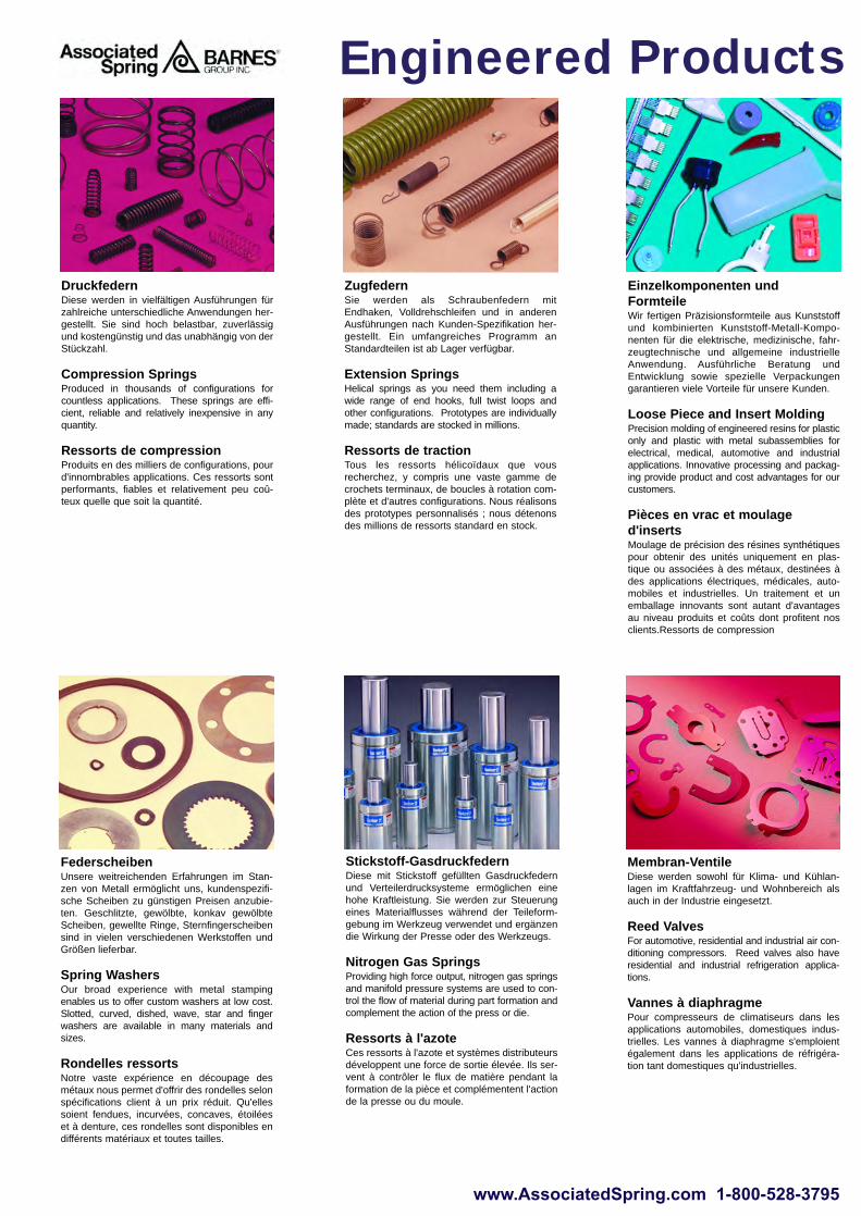
Engineered Products
Membran-VentileDiese werden sowohl für Klima- und Kühlan-lagen im Kraftfahrzeug- und Wohnbereich alsauch in der Industrie eingesetzt.
Reed ValvesFor automotive, residential and industrial air con-ditioning compressors. Reed valves also haveresidential and industrial refrigeration applica-tions.
Vannes à diaphragme Pour compresseurs de climatiseurs dans lesapplications automobiles, domestiques indus-trielles. Les vannes à diaphragme s'emploientégalement dans les applications de réfrigéra-tion tant domestiques qu'industrielles.
www.AssociatedSpring.com 1-800-528-3795
DruckfedernDiese werden in vielfältigen Ausführungen fürzahlreiche unterschiedliche Anwendungen her-gestellt. Sie sind hoch belastbar, zuverlässigund kostengünstig und das unabhängig von derStückzahl.
Compression SpringsProduced in thousands of configurations forcountless applications. These springs are effi-cient, reliable and relatively inexpensive in anyquantity.
Ressorts de compressionProduits en des milliers de configurations, pourd'innombrables applications. Ces ressorts sontperformants, fiables et relativement peu coû-teux quelle que soit la quantité.
FederscheibenUnsere weitreichenden Erfahrungen im Stan-zen von Metall ermöglicht uns, kundenspezifi-sche Scheiben zu günstigen Preisen anzubie-ten. Geschlitzte, gewölbte, konkav gewölbteScheiben, gewellte Ringe, Sternfingerscheibensind in vielen verschiedenen Werkstoffen undGrößen lieferbar.
Spring WashersOur broad experience with metal stampingenables us to offer custom washers at low cost.Slotted, curved, dished, wave, star and fingerwashers are available in many materials andsizes.
Rondelles ressortsNotre vaste expérience en découpage desmétaux nous permet d'offrir des rondelles selonspécifications client à un prix réduit. Qu'ellessoient fendues, incurvées, concaves, étoiléeset à denture, ces rondelles sont disponibles endifférents matériaux et toutes tailles.
ZugfedernSie werden als Schraubenfedern mitEndhaken, Volldrehschleifen und in anderenAusführungen nach Kunden-Spezifikation her-gestellt. Ein umfangreiches Programm anStandardteilen ist ab Lager verfügbar.
Extension SpringsHelical springs as you need them including awide range of end hooks, full twist loops andother configurations. Prototypes are individuallymade; standards are stocked in millions.
Ressorts de tractionTous les ressorts hélicoïdaux que vousrecherchez, y compris une vaste gamme decrochets terminaux, de boucles à rotation com-plète et d'autres configurations. Nous réalisonsdes prototypes personnalisés ; nous détenonsdes millions de ressorts standard en stock.
Einzelkomponenten undFormteileWir fertigen Präzisionsformteile aus Kunststoffund kombinierten Kunststoff-Metall-Kompo-nenten für die elektrische, medizinische, fahr-zeugtechnische und allgemeine industrielleAnwendung. Ausführliche Beratung undEntwicklung sowie spezielle Verpackungengarantieren viele Vorteile für unsere Kunden.
Loose Piece and Insert MoldingPrecision molding of engineered resins for plasticonly and plastic with metal subassemblies forelectrical, medical, automotive and industrialapplications. Innovative processing and packag-ing provide product and cost advantages for ourcustomers.
Pièces en vrac et moulage d'insertsMoulage de précision des résines synthétiquespour obtenir des unités uniquement en plas-tique ou associées à des métaux, destinées àdes applications électriques, médicales, auto-mobiles et industrielles. Un traitement et unemballage innovants sont autant d'avantagesau niveau produits et coûts dont profitent nosclients.Ressorts de compression
Stickstoff-GasdruckfedernDiese mit Stickstoff gefüllten Gasdruckfedernund Verteilerdrucksysteme ermöglichen einehohe Kraftleistung. Sie werden zur Steuerungeines Materialflusses während der Teileform-gebung im Werkzeug verwendet und ergänzendie Wirkung der Presse oder des Werkzeugs.
Nitrogen Gas SpringsProviding high force output, nitrogen gas springsand manifold pressure systems are used to con-trol the flow of material during part formation andcomplement the action of the press or die.
Ressorts à l'azoteCes ressorts à l'azote et systèmes distributeursdéveloppent une force de sortie élevée. Ils ser-vent à contrôler le flux de matière pendant laformation de la pièce et complémentent l'actionde la presse ou du moule.
Sicherungsringe und SprengringeSicherungsringe für Wellen und Bohrungengemäß DIN 471/472 u.a. sowie nach kunden-spezifischen Anforderungen. Diese Ringe wer-den aus unterschiedlichen Werkstoffen und mitverschiedenen Oberflächenbeschichtungenhergestellt. Ein umfangreiches Sortiment ist abLager verfügbar.
Snap/Retaining RingsInternal, external and special application ringsproduced from a variety of ferrous and non-fer-rous materials. Our rings are available with orwithout special coatings for lubricity and/or corro-sion protection. We have an extensive stock cat-alogue of DIN 471/472 and other metric rings.
Circlips et anneaux de retenueCirclips internes, externes pour applicationsspéciales, produits dans toute une variété dematériaux. Nos anneaux sont disponibles avecou sans revêtements spéciaux. Nous détenonsun vaste catalogue de circlips en stock selonDIN 471 / 472, et d'autres circlips métriques.
BlattfedernWir fertigen Rohteile oder Formteile nach Kun-denwunsch in jeder Stückzahl. Diese Federnwerden zur Sicherung von Teilen, in Schar-nieren, Schellen und Haltern und als Sperr-Elemente eingesetzt.
Flat SpringsCustom-designed parts blanked and formed inany volume. Applications include retaining partsin place, serving as stops, hinges, connectors,braces, fasteners, etc.
Ressorts platsPièces sur mesure découpées et formées, entoutes quantités. Les applications incluent lemaintien de pièces sur leur emplacement, l'em-ploi comme butées, charnières, connecteurs,colliers, supports, etc.
Trieb-/FlachspiralfedernTrieb-/Flachspiralfedern sind in vielfältigenGrößen lieferbar und sind für die unterschied-lichsten Befestigungen, wie zum Beispiel beiTaktgeber-Motoren, Ausgleichsmechanik, Spu-lenrücklauf- und Rückspulgeräten im Einsatz.
Power/Flat Spiral SpringsPower/Flat Spiral Springs are available in a widerange of sizes and attachment methods for clockand mechanical motors, counterbalance mecha-nisms, reel returns and rewind devices.
Ressorts d'entraînement / hélicoïdaux plats Ces ressorts d'entraînement / hélicoïdaux platssont disponibles dans une vaste gamme detailles et de méthodes de fixation. Ils servent àentraîner des horloges et moteurs mécaniques,des mécanismes de compensation, à com-mander le retour de bobines et des dispositifsde rembobinage.
Engineered Products
Elektronische BauteilePräsizisions-Miniatur-Stanzteile, Drahtformteileund Induktoren für die Bereiche Telekom-munikation, Computer- und Bildröhren werdennach Kundenwunsch gefertigt. Wir bieten spe-zielle Beschichtungen mit Edelmetallen sowieMontage in Band- oder magazinierter Form.
Electronic ComponentsPrecision miniature stampings, wire forms andinductors for telecommunications, computers andpicture tubes. We offer precious metal plating,assembly, and tape and reel packaging.
Composants électroniquesPièces miniature estampées avec précision,pièces filaires moulées et inducteurs pour lestélécommunications, les ordinateurs et lestubes cathodiques. Nous proposons le revête-ment en métal précieux, l'assemblage et leconditionnement des rubans et bobines.
Schwerlast-FedernWir wickeln Draht bis zu einem Durchmesservon 15,24 mm (0,600 “) zu hoch belastbarenFedern, die in Agrar- und Baumaschinen ver-wendet werden. Kapazitäten für große und klei-ne Stückzahlen sind vorhanden.
Heavy CoilingWe coil wire with diameters up to .600"(15.24mm) for springs used in farm and con-struction equipment. Capacity for low and highvolume orders.
Enroulages fortes chargesNous enroulons les fils jusqu'à une sectionmaxi. de 15,24 mm (0,6 pouce), pour obtenirdes ressorts entrant dans les équipements agri-coles et de construction. Nos capacités sontadaptées aux commandes de petits et grandsvolumes.
Akkordeon-Federn Akkordeon-Federn sind speziell hergestellt, umauf einer bestimmten Höhe eine vorgegebeneBelastung zu gewährleisten. Eine Vielzahl vonkundenspezifischen Ausführungen und Werk-stoffen wird zum Beispiel in der Kupplungs-mechanik von automatischen Getrieben einge-setzt.
Accordion SpringsAccordion springs are specially engineered toprovide a specified load at a particular height.Widely used in a range of custom sizes andmaterials for clutching mechanisms in automatictransmissions.
Ressorts en accordéonLes ressorts en accordéon sont spécialementconçus pour développer une charge spécifiqueà une hauteur particulière. Ils s'emploientcouramment dans des tailles et matériaux per-sonnalisés, dans les mécanismes d'embrayageintégrés dans les boîtes automatiques.
TorsionsfedernTorsionsfedern werden sowohl als Miniatur-Drehfedern in Elektronikgeräten als auch alshoch belastbare Drehfedern, wie zum Beispielin Sitzkonstruktionen, verwendet.
Torsion SpringsTorsion springs are used for hinges, counterbal-ances and lever return applications. Sizes rangefrom miniature used in electronic devices to largetorsion springs used in chair control units.
Ressorts de torsionLes ressorts de torsion servent pour lescharnières, les mécanismes de compensationet les applications à renvoi de levier. La gammeva des tailles miniatures employées dans lesdispositifs électroniques aux ressorts de torsiongrand format employés dans les mécanismesde commande des chaises.
Federn für Kfz-Ventile und GetriebeWir fertigen Präzisions-Schraubendruckfedernwie zum Beispiel für Motorventile oderDrehmomentwandler. Wir unterstützen Sie beider Auslegung und Konstruktion und fertigenauch Prototypen. Wir garantieren die Einhal-tung hochspezifischer Anforderungen zu opti-mierten Kosten.
Automotive Valve & TransmissionPrecision helical compression springs (enginevalve, torque converter clutch, arcuate).Engineered, designed, prototyped, and manufac-tured to meet specific demands at optimizedcosts.
Soupapes et transmissions automobilesRessorts de compression hélicoïdaux de préci-sion (pour soupapes de moteurs, embrayagesà conversion de couple, arqués). Conception,ingénierie, prototypes et fabrication à un coûtoptimisé pour répondre à des exigences trèsspécifiques.
BaugruppenWir bieten umfangreiche Möglichkeiten für dieMontage von Einzelteilen zu komplexen Bau-gruppen sowie zu fertigen Produkten. UnserAngebot umfaßt schlüsselfertige Systeme:Montage, Prüfung und Verpackung gemäßKundenspezifikation.
SubassembliesWide capabilities in assembling parts into sub-assemblies and finished products. We provideturnkey convenience - assembly, testing andpackaging to order.
Sous-ensemblesVastes possibilités d'assemblage des piècespour obtenir des sous-ensembles et produitsfinis. Nous proposons des systèmes clé enmain - le montage, les essais et le condition-nement sur commande.
StanztechnikWir bieten Unterstützung bei der Entwicklung,Konstruktion und Herstellung von Stanzteilen injeder Form und Größe aus den unterschiedlich-sten Werksktoffen. Auch kleine Stückzahlensind möglich.
Engineered StampingsWe offer design, engineering and productionassistance for stampings in any shape, size ormetal. Available in any quantity.
Pièces estampées complexesNous offrons la conception, l'ingénierie et l'as-sistance à la production de pièces estampéesdans toutes les géométries, tailles et métaux,quel que soit le volume de la commande.
Tellerfedern, Typ “Belleville”Belleville Tellerfederscheiben lösen das Pro-blem hoher Belastungen auf begrenztemRaum, wie zum Beispiel in Gertriebekupp-lungen, Klinken und Tellerfederpaketen. Durcheine Kombination dieser Teile in unterschiedli-cher Reihenfolge können wir eine Vielzahl vonBelastungsvarianten anbieten.
Belleville Disc SpringsBelleville spring washers solve problems of highloads in limited space such as in transmissionclutch assemblies, detents and loading fasten-ers. By combining them in various sequences,we can offer a number of load-carrying possibili-ties.
Ressorts assiettes du typeBellevilleLes ressorts assiettes Belleville résolvent lesproblèmes que posent les charges lourdes surespace réduit, rencontrées par ex. dans lesembrayages de transmission, les mécanismesde détente et les fixations de charges. En com-binant ces ressorts dans des ordres différents,nous offrons des possibilités multiples d'ab-sorption de la charge.
DrahtformteileFormteile mit Drahtdurchmesser von 0,1 bis 12mm (0.004” bis 0,5”) können zu Klammern,Klemmen und weiteren statischen Lasteinhei-ten angeboten werden. Viele verschiedenekonstruktive Möglichkeiten stehen kostengün-stig zur Verfügung unter Einsatz von Standart-werkzeugen.
Wire FormsWire sizes ranging from .004" to .500" (.1-12mm)diameter offer configurations for clips, clampsand other static-load devices with short workingranges. Many designs are economically pro-duced using standard tooling.
Fils formésLes sections de fils comprises entre 0,1 et 12mm (0,004 et 0,5 pouce) permettent de config-urer des clips, brides et autres dispositifsdéveloppant une charge statique, à course detravail courte. De nombreuses géométries sontdisponibles à bas prix grâce à un outillagestandard.
Engineered Products
www.AssociatedSpring.com 1-800-528-37956/2002
Related Documents


