RIGOL User’s Guide EMI Test System PC Software Aug. 2014 RIGOL Technologies, Inc.

Welcome message from author
This document is posted to help you gain knowledge. Please leave a comment to let me know what you think about it! Share it to your friends and learn new things together.
Transcript
RIGOL
User’s Guide
EMI Test System PC Software
Aug. 2014
RIGOL Technologies, Inc.

RIGOL
User’s Guide for EMI Test System I
Guaranty and Declaration Copyright © 2014 RIGOL Technologies, Inc. All Rights Reserved. Trademark Information RIGOL is a registered trademark of RIGOL Technologies, Inc. Publication Number UGD13100-1110 Notices RIGOL products are covered by P.R.C. and foreign patents, issued and
pending. RIGOL reserves the right to modify or change parts of or all the
specifications and pricing policies at company’s sole decision. Information in this publication replaces all previously corresponding material. Information in this publication is subject to change without notice. RIGOL shall not be liable for either incidental or consequential losses in
connection with the furnishing, use or performance of this manual as well as any information contained.
Any part of this document is forbidden to be copied, photocopied or rearranged without prior written approval of RIGOL.
Product Certification RIGOL guarantees this product conforms to the national and industrial standards in China as well as the ISO9001:2008 standard and the ISO14001:2004 standard. Other international standard conformance certification is in progress. Contact Us If you have any problem or requirement when using our products or this manual, please contact RIGOL. E-mail: [email protected] Website: www.rigol.com

RIGOL
II User’s Guide for EMI Test System
Safety Requirement
General Safety Summary Please review the following safety precautions carefully before putting the instrument into operation so as to avoid any personal injury or damage to the instrument and any product connected to it. To prevent potential hazards, please use the instrument only specified by this manual. Use Proper Power Cord. Only the power cord designed for the instrument and authorized for use within the local country could be used.
Ground the Instrument. The instrument is grounded through the Protective Earth lead of the power cord. To avoid electric shock, it is essential to connect the earth terminal of the power cord to the Protective Earth terminal before connecting any inputs or outputs.
Connect the Probe Correctly. If a probe is used, do not connect the ground lead to high voltage since it has isobaric electric potential as the ground.
Observe All Terminal Ratings. To avoid fire or shock hazard, observe all ratings and markers on the instrument and check your manual for more information about ratings before connecting the instrument.
Use Proper Overvoltage Protection. Make sure that no overvoltage (such as that caused by a thunderstorm) can reach the product, or else the operator might be exposed to the danger of electrical shock.
Do Not Operate Without Covers. Do not operate the instrument with covers or panels removed.
RIGOL
User’s Guide for EMI Test System III
Do Not Insert Anything Into the Holes of Fan. Do not insert anything into the holes of the fan to avoid damaging the instrument. Use Proper Fuse. Please use the specified fuses.
Avoid Circuit or Wire Exposure. Do not touch exposed junctions and components when the unit is powered. Do Not Operate With Suspected Failures. If you suspect damage occurs to the instrument, have it inspected by qualified service personnel before further operations. Any maintenance, adjustment or replacement especially to circuits or accessories must be performed by RIGOL authorized personnel.
Keep Well Ventilation. Inadequate ventilation may cause an increase of temperature or damage to the device. So please keep the instrument well ventilated and inspect the intake and fan regularly. Do Not Operate in Wet Conditions. In order to avoid short circuiting to the interior of the device or electric shock, please do not operate the instrument in a humid environment.
Do Not Operate in an Explosive Atmosphere. In order to avoid damage to the device or personal injuries, it is important to operate the device away from an explosive atmosphere. Keep Product Surfaces Clean and Dry. To avoid the influence of dust and/or moisture in the air, please keep the surface of the device clean and dry. Electrostatic Prevention. Operate the instrument in an electrostatic discharge protective environment to avoid damage induced by static discharges. Always ground both the internal and external conductors of cables to release static before making connections.
RIGOL
IV User’s Guide for EMI Test System
Proper Use of Battery. If a battery is supplied, it must not be exposed to high temperature or in contact with fire. Keep it out of the reach of children. Improper change of battery (note: lithium battery) may cause explosion. Use RIGOL specified battery only. Handling Safety. Please handle with care during transportation to avoid damage to buttons, knob interfaces and other parts on the panels.
Safety Terms and Symbols Terms Used in this Manual. These terms may appear in this manual:
WARNING Warning statements indicate conditions or practices that could result in injury or loss of life.
CAUTION
Caution statements indicate conditions or practices that could result in damage to this product or other property.
Terms Used on the Product. These terms may appear on the Product: DANGER indicates an injury or hazard may immediately happen. WARNING indicates an injury or hazard may occur. CAUTION indicates potential damage to the instrument or other property might
occur. Symbols Used on the Product. These symbols may appear on the product:
Hazardous Voltage
Safety Warning
Protective Earth Terminal
Chassis Ground
Test Ground
RIGOL
User’s Guide for EMI Test System V
Allgemeine Sicherheits Informationen Überprüfen Sie diefolgenden Sicherheitshinweise sorgfältigumPersonenschädenoderSchäden am Gerätundan damit verbundenen weiteren Gerätenzu vermeiden. Zur Vermeidung vonGefahren, nutzen Sie bitte das Gerät nur so, wiein diesem Handbuchangegeben. Um Feuer oder Verletzungen zu vermeiden, verwenden Sie ein ordnungsgemäßes Netzkabel. Verwenden Sie für dieses Gerät nur das für ihr Land zugelassene und genehmigte Netzkabel. Erden des Gerätes. Das Gerät ist durch den Schutzleiter im Netzkabel geerdet. Um Gefahren durch elektrischen Schlag zu vermeiden, ist es unerlässlich, die Erdung durchzuführen. Erst dann dürfen weitere Ein- oder Ausgänge verbunden werden. Anschluss einesTastkopfes. Die Erdungsklemmen der Sonden sindauf dem gleichen Spannungspegel des Instruments geerdet. SchließenSie die Erdungsklemmen an keine hohe Spannung an. Beachten Sie alle Anschlüsse. Zur Vermeidung von Feuer oder Stromschlag, beachten Sie alle Bemerkungen und Markierungen auf dem Instrument. Befolgen Sie die Bedienungsanleitung für weitere Informationen, bevor Sie weitere Anschlüsse an das Instrument legen. Verwenden Sie einen geeigneten Überspannungsschutz. Stellen Sie sicher, daß keinerlei Überspannung (wie z.B. durch Gewitter verursacht) das Gerät erreichen kann. Andernfallsbestehtfür den Anwender die GefahreinesStromschlages. Nicht ohne Abdeckung einschalten. Betreiben Sie das Gerät nicht mit entfernten Gehäuse-Abdeckungen. Betreiben Sie das Gerät nicht geöffnet. Der Betrieb mit offenen oder entfernten Gehäuseteilen ist nicht zulässig. Nichts in entsprechende Öffnungen stecken (Lüfter z.B.) Passende Sicherung verwenden. Setzen Sie nur die spezifikationsgemäßen Sicherungen ein. Vermeiden Sie ungeschützte Verbindungen. Berühren Sie keine unisolierten Verbindungen oder Baugruppen, während das

RIGOL
VI User’s Guide for EMI Test System
Gerät in Betrieb ist. Betreiben Sie das Gerät nicht im Fehlerfall. Wenn Sie am Gerät einen Defekt vermuten, sorgen Sie dafür, bevor Sie das Gerät wieder betreiben, dass eine Untersuchung durch qualifiziertes Kundendienstpersonal durchgeführt wird.Jedwede Wartung, Einstellarbeiten oder Austausch von Teilen am Gerät, sowie am Zubehör dürfen nur von RIGOL autorisiertem Personal durchgeführt werden. Belüftung sicherstellen. Unzureichende Belüftung kann zu Temperaturanstiegen und somit zu thermischen Schäden am Gerät führen. Stellen Sie deswegen die Belüftung sicher und kontrollieren regelmäßig Lüfter und Belüftungsöffnungen. Nicht in feuchter Umgebung betreiben. Zur Vermeidung von Kurzschluß im Geräteinneren und Stromschlag betreiben Sie das Gerät bitte niemals in feuchter Umgebung. Nicht in explosiver Atmosphäre betreiben. Zur Vermeidung von Personen- und Sachschäden ist es unumgänglich, das Gerät ausschließlich fernab jedweder explosiven Atmosphäre zu betreiben. Geräteoberflächen sauber und trocken halten. Um den Einfluß von Staub und Feuchtigkeit aus der Luft auszuschließen, halten Sie bitte die Geräteoberflächen sauber und trocken. Schutz gegen elektrostatische Entladung (ESD). Sorgen Sie für eine elektrostatisch geschützte Umgebung, um somit Schäden und Funktionsstörungen durch ESD zu vermeiden. Erden Sie vor dem Anschluß immer Innen- und Außenleiter der Verbindungsleitung, um statische Aufladung zu entladen. Die richtige Verwendung desAkku. Wenneine Batterieverwendet wird, vermeiden Sie hohe Temperaturen bzw. Feuer ausgesetzt werden.Bewahren Sie es außerhalbder Reichweitevon Kindern auf.UnsachgemäßeÄnderung derBatterie(Anmerkung:Lithium-Batterie)kann zu einer Explosion führen. VerwendenSie nur von RIGOLangegebenenAkkus. Sicherer Transport. Transportieren Sie das Gerät sorgfältig (Verpackung!), um Schäden an Bedienelementen, Anschlüssen und anderen Teilen zu vermeiden.
RIGOL
User’s Guide for EMI Test System VII
Sicherheits Begriffe und Symbole Begriffe in diesem Guide. Diese Begriffe können in diesem Handbuch auftauchen:
WARNING Die Kennzeichnung WARNING beschreibt Gefahrenquellen die leibliche Schäden oder den Tod von Personen zur Folge haben können.
CAUTION Die Kennzeichnung Caution (Vorsicht) beschreibt Gefahrenquellen die Schäden am Gerät hervorrufen können.
Begriffe auf dem Produkt. Diese Bedingungen können auf dem Produkt erscheinen: DANGER weist auf eine Verletzung oder Gefährdung hin, die sofort
geschehen kann. WARNING weist auf eine Verletzung oder Gefährdung hin, die möglicherweise
nicht sofort geschehen. CAUTION bedeutet, dass eine mögliche Beschädigung des Instruments oder
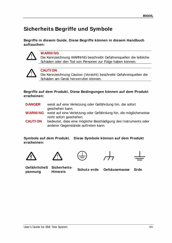
anderer Gegenstände auftreten kann. Symbole auf dem Produkt. Diese Symbole können auf dem Produkt erscheinen:
GefährlicheSpannung
Sicherheits- Hinweis Schutz-erde Gehäusemasse Erde
RIGOL
VIII User’s Guide for EMI Test System
General Care and Cleaning General Care: Do not store or leave the instrument where it may be exposed to direct sunlight for long periods of time. Cleaning: Clean the instrument regularly according to its operating conditions. To clean the exterior surface, perform the following steps: 1. Disconnect the instrument from all power sources. 2. Clean the loose dust on the outside of the instrument with a lint-free cloth
(with a mild detergent or water). When cleaning the LCD, take care to avoid scarifying it.
CAUTION
To avoid damage to the instrument, do not expose it to caustic liquids.
WARNING To avoid injury resulting from short circuit, make sure the instrument is completely dry before reconnecting to a power source.
RIGOL
User’s Guide for EMI Test System IX
Environmental Considerations The following symbol indicates that this product complies with the WEEE Directives 2002/96/EC.
Product End-of-Life Handling The equipment may contain substances that could be harmful to the environment or human health. In order to avoid the release of such substances into the environment and harm to human health, we encourage you to recycle this product in an appropriate system that will ensure that most of the materials are reused or recycled appropriately. Please contact your local authorities for disposal or recycling information.
RIGOL
X User’s Guide for EMI Test System
EMI Test System Overview EMI Test System is a PC application software developed by RIGOL for DSA1000A, DSA1000 and DSA800 (with the EMI-DSA800 option) with the EMI function. It can be used to perform conduction and radiation EMI tests. This software is designed on the basis of the standard drive VISA and you can realize the communication between the software and instrument via USB-TMC or LAN interface to control the instrument. Main Features:
Provide amplitude correction function. You can edit the scan list and perform scan by segments to improve the
measurement speed. The limit line function can be used to quickly judge the measurement results. Provide fast pre-scan and final scan modes. Provide peak search function. You can define and save the peak list. The frequency axis supports linear and log scale display. Auto generation of test report.
RIGOL
User’s Guide for EMI Test System XI
Document Overview This manual is used to guide users to perform EMI (Electromagnetic Interference) pre-compliance test using EMI Test System and RIGOL spectrum analyzer. Topics in this manual: Chapter 1 To Install and Run the Software This chapter introduces the configuration requirements, installation and running methods of the software. Chapter 2 Trial and Activation This chapter introduces the trial and activation methods of the software. Chapter 3 Interface Layout This chapter introduces the interface layout and basic functions of the software. Chapter 4 Function Overview This chapter introduces the recommended test procedures as well as the main functions of the software. Chapter 5 To Edit the Amplitude Correction Data This chapter introduces how to edit the amplitude correction data using the software. Chapter 6 To Set the Scan Parameters This chapter introduces how to set the scan parameters using the software. Chapter 7 To Edit the Limit Line This chapter introduces how to edit the limit line data using the software. Chapter 8 To Perform Pre-scan This chapter introduces how to perform pre-scan using the software. Chapter 9 To Perform Peak Search This chapter introduces how to perform peak search using the software.
RIGOL
XII User’s Guide for EMI Test System
Chapter 10 To Perform Final Scan This chapter introduces how to perform final scan using the software. Chapter 11 To Generate a Test Report This chapter introduces how to generate a test report using the software. Chapter 12 Specifications This chapter lists the specification of the software. Chapter 13 Appendix This chapter introduces the marker editing methods as well as provides the order information and warranty information. User manuals provided with this software: Data sheet, User’s Guide, Help Document and etc. For the desired manual, please download it from www.rigol.com.
Contents RIGOL
User’s Guide for EMI Test System XIII
Contents
Guaranty and Declaration ......................................................................... I
Safety Requirement ................................................................................ II
General Safety Summary ........................................................................... II
Safety Terms and Symbols ....................................................................... IV
Allgemeine Sicherheits Informationen ......................................................... V
Sicherheits Begriffe und Symbole ............................................................. VII
General Care and Cleaning ..................................................................... VIII
Environmental Considerations ................................................................... IX
EMI Test System Overview ...................................................................... X
Document Overview ............................................................................... XI
Chapter 1 To Install&Run the Software ................................................ 1-1
Configuration Requirements ................................................................... 1-2
To Install the Software ........................................................................... 1-2
To Run the Software .............................................................................. 1-3
To Connect the Instrument .............................................................. 1-3
To Start the Software ...................................................................... 1-6
To View the Help Document ............................................................. 1-8
Chapter 2 Trial and Activation ............................................................... 2-1
Trial ..................................................................................................... 2-2
Activation ............................................................................................. 2-3
Chapter 3 Interface Layout ................................................................... 3-1
Chapter 4 Function Overview ................................................................ 4-1
Chapter 5 To Edit the Amplitude Correction Data.................................. 5-1
To Edit the Correction Data .................................................................... 5-2
To Select Correction Factor(s) ................................................................. 5-3
To Enable the Correction Function ........................................................... 5-3
Chapter 6 To Set the Scan Parameters .................................................. 6-1
To Configure the Pre-scan Parameters ..................................................... 6-2
To Configure the Segment Scan Parameters ............................................. 6-3
RIGOL Contents
XIV User’s Guide for EMI Test System
To Set the Scan Sub-range Parameters .............................................. 6-3
To Edit the Scan List Data ................................................................. 6-4
To Configure the Final Scan Parameters ................................................... 6-5
Chapter 7 To Edit the Limit Line ........................................................... 7-1
To Edit the Limit Line Data ...................................................................... 7-2
To Operate the Limit Line List .................................................................. 7-3
Chapter 8 To Perform Pre-scan ............................................................ 8-1
Chapter 9 To Perform Peak Search ....................................................... 9-1
To Set the Peak Search Parameters .......................................................... 9-2
To Edit the Peak Search List .................................................................... 9-3
To Operate the Peak Search List .............................................................. 9-4
Chapter 10 To Perform Final Scan ...................................................... 10-1
Chapter 11 To Generate a Test Report ............................................... 11-1
Chapter 12 Specifications ................................................................... 12-1
Chapter 13 Appendix .......................................................................... 13-1
Appendix A: To Edit the Marker ............................................................. 13-1
Appendix B: Ordering Information ......................................................... 13-4
Appendix C: Warranty ........................................................................... 13-5
Chapter 1 To Install&Run the Software RIGOL
User’s Guide for EMI Test System 1-1
Chapter 1 To Install&Run the Software Before using EMI Test System, you need to know the configuration requirements, installation procedures and running methods of the software. Subjects in this chapter:
Configuration Requirements To Install the Software To Run the Software
RIGOL Chapter 1 To Install&Run the Software
1-2 User’s Guide for EMI Test System
Configuration Requirements Before using EMI Test System, make sure that your PC fulfills the following configuration requirements. Hardware Configuration Requirements Internal Memory: 1 GB and higher (2 GB and higher is recommended) Monitor: 1024×800 resolution or higher Processor: 1 GHz and higher Hard Disk: 200 MB and higher Running Environment Operation System: Windows XP (32-bit, Chinese or English), Windows 7
(32-bit, Chinese or English), Windows 8.1 (64-bit, English) PC Administrator Permission: you must log in the PC using administrator
account RIGOL PC software Ultra Sigma 00.01.06.00 or higher version is installed
To Install the Software 1. Before installing the software, install Ultra Sigma 00.01.06.00 or higher version.
For the installation procedures, refer to the related Ultra Sigma document. 2. RIGOL provides the EMI Test System PC software installation package (you
can download it from www.rigol.com). Double-click EMI Test System.exe and click "Next" to install the software following the instructions. After EMI Test System is correctly installed, a shortcut icon named "EMI Test System" is displayed on the PC desktop.
Chapter 1 To Install&Run the Software RIGOL
User’s Guide for EMI Test System 1-3
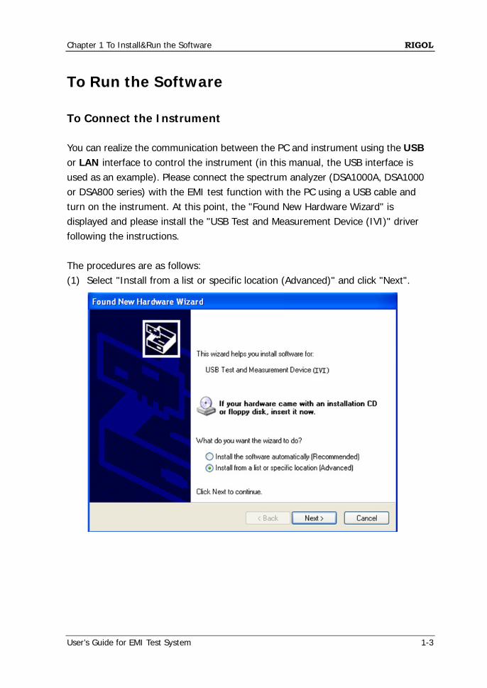
To Run the Software To Connect the Instrument You can realize the communication between the PC and instrument using the USB or LAN interface to control the instrument (in this manual, the USB interface is used as an example). Please connect the spectrum analyzer (DSA1000A, DSA1000 or DSA800 series) with the EMI test function with the PC using a USB cable and turn on the instrument. At this point, the "Found New Hardware Wizard" is displayed and please install the "USB Test and Measurement Device (IVI)" driver following the instructions. The procedures are as follows: (1) Select "Install from a list or specific location (Advanced)" and click "Next".
RIGOL Chapter 1 To Install&Run the Software
1-4 User’s Guide for EMI Test System
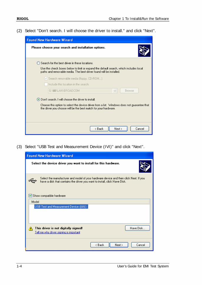
(2) Select "Don't search. I will choose the driver to install." and click "Next".
(3) Select "USB Test and Measurement Device (IVI)" and click "Next".

Chapter 1 To Install&Run the Software RIGOL
User’s Guide for EMI Test System 1-5
(4) Click "Finish" when the installation is finished.
RIGOL Chapter 1 To Install&Run the Software
1-6 User’s Guide for EMI Test System
To Start the Software After EMI Test System is successfully installed, you can start the software via the following two methods. (1) Via the [Start] menu or the shortcut icon on the PC desktop
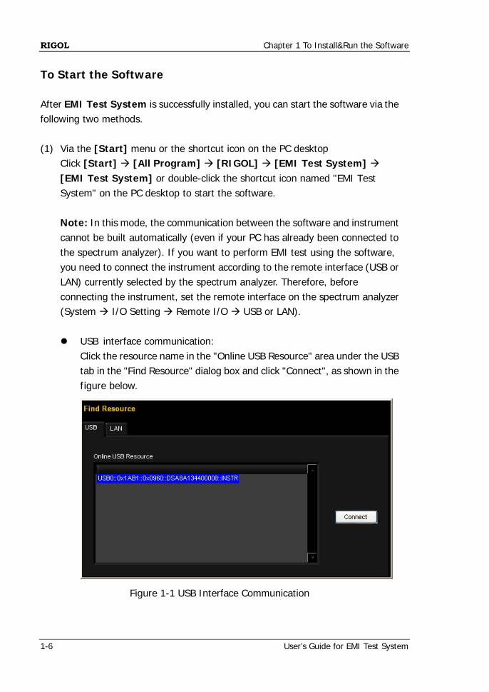
Click [Start] [All Program] [RIGOL] [EMI Test System] [EMI Test System] or double-click the shortcut icon named "EMI Test System" on the PC desktop to start the software. Note: In this mode, the communication between the software and instrument cannot be built automatically (even if your PC has already been connected to the spectrum analyzer). If you want to perform EMI test using the software, you need to connect the instrument according to the remote interface (USB or LAN) currently selected by the spectrum analyzer. Therefore, before connecting the instrument, set the remote interface on the spectrum analyzer (System I/O Setting Remote I/O USB or LAN). USB interface communication:
Click the resource name in the "Online USB Resource" area under the USB tab in the "Find Resource" dialog box and click "Connect", as shown in the figure below.
Figure 1-1 USB Interface Communication
Chapter 1 To Install&Run the Software RIGOL
User’s Guide for EMI Test System 1-7
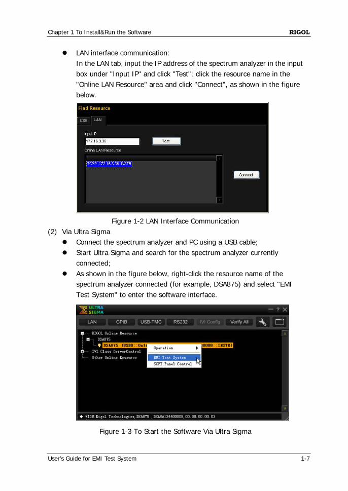
LAN interface communication: In the LAN tab, input the IP address of the spectrum analyzer in the input box under "Input IP" and click "Test"; click the resource name in the "Online LAN Resource" area and click "Connect", as shown in the figure below.
Figure 1-2 LAN Interface Communication
(2) Via Ultra Sigma Connect the spectrum analyzer and PC using a USB cable; Start Ultra Sigma and search for the spectrum analyzer currently
connected; As shown in the figure below, right-click the resource name of the
spectrum analyzer connected (for example, DSA875) and select "EMI Test System" to enter the software interface.
Figure 1-3 To Start the Software Via Ultra Sigma
RIGOL Chapter 1 To Install&Run the Software
1-8 User’s Guide for EMI Test System
Note: When the software is started via this method, the communication between the software and spectrum analyzer is built automatically (make sure that your PC has already been connected to the spectrum analyzer).
To View the Help Document When the software is successfully installed, you can view the help document in the following two modes. (1) Click [Start] [All Program] [RIGOL] [EMI Test System] to open
the EMI Test System_Help Document_CN or EMI Test System_Help Document_E to view the specific functions and applications of the software.
(2) Start the software and click in the software main interface to recall the
corresponding help document.
Chapter 2 Trial and Activation RIGOL
User’s Guide for EMI Test System 2-1
Chapter 2 Trial and Activation
Subjects in this chapter:
Trial Activation
RIGOL Chapter 2 Trial and Activation
2-2 User’s Guide for EMI Test System
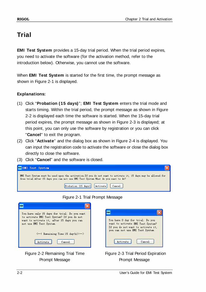
Trial EMI Test System provides a 15-day trial period. When the trial period expires, you need to activate the software (for the activation method, refer to the introduction below). Otherwise, you cannot use the software. When EMI Test System is started for the first time, the prompt message as shown in Figure 2-1 is displayed. Explanations:
(1) Click “Probation (15 days)”; EMI Test System enters the trial mode and starts timing. Within the trial period, the prompt message as shown in Figure 2-2 is displayed each time the software is started. When the 15-day trial period expires, the prompt message as shown in Figure 2-3 is displayed; at this point, you can only use the software by registration or you can click "Cancel" to exit the program.
(2) Click “Activate” and the dialog box as shown in Figure 2-4 is displayed. You can input the registration code to activate the software or close the dialog box directly to close the software.
(3) Click “Cancel” and the software is closed.
Figure 2-1 Trial Prompt Message
Figure 2-2 Remaining Trial Time
Prompt Message
Figure 2-3 Trial Period Expiration
Prompt Message
Chapter 2 Trial and Activation RIGOL
User’s Guide for EMI Test System 2-3
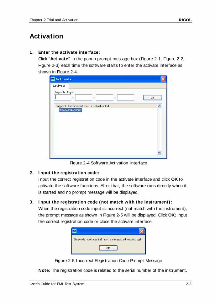
Activation 1. Enter the activate interface:
Click "Activate" in the popup prompt message box (Figure 2-1, Figure 2-2, Figure 2-3) each time the software starts to enter the activate interface as shown in Figure 2-4.
Figure 2-4 Software Activation Interface
2. Input the registration code: Input the correct registration code in the activate interface and click OK to activate the software functions. After that, the software runs directly when it is started and no prompt message will be displayed.
3. Input the registration code (not match with the instrument): When the registration code input is incorrect (not match with the instrument), the prompt message as shown in Figure 2-5 will be displayed. Click OK; input the correct registration code or close the activate interface.
Figure 2-5 Incorrect Registration Code Prompt Message
Note: The registration code is related to the serial number of the instrument.

Chapter 3 Interface Layout RIGOL
User’s Guide for EMI Test System 3-1
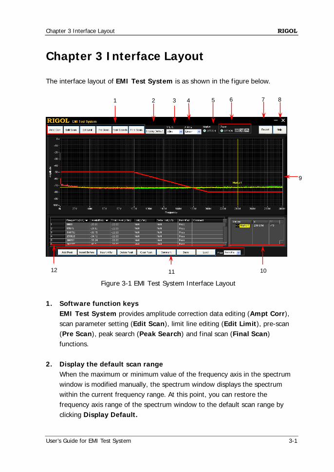
Chapter 3 Interface Layout The interface layout of EMI Test System is as shown in the figure below.
Figure 3-1 EMI Test System Interface Layout 1. Software function keys
EMI Test System provides amplitude correction data editing (Ampt Corr), scan parameter setting (Edit Scan), limit line editing (Edit Limit), pre-scan (Pre Scan), peak search (Peak Search) and final scan (Final Scan) functions.
2. Display the default scan range
When the maximum or minimum value of the frequency axis in the spectrum window is modified manually, the spectrum window displays the spectrum within the current frequency range. At this point, you can restore the frequency axis range of the spectrum window to the default scan range by clicking Display Default.
8 1 2 3 4 5 6 7
9
11 10 12
RIGOL Chapter 3 Interface Layout
3-2 User’s Guide for EMI Test System
Tip:
Here, the default scan range refers to the frequency axis range (the actual value depends on the model of the spectrum analyzer) of the spectrum window after the software is correctly connected to the spectrum analyzer or the frequency axis range (the actual value depends on the pre-scan range set by users) of the spectrum window after the software performs pre-scan.
3. Y-axis unit
Click the dropdown arrow in this box and select dBm, dBmV or dBuV in the dropdown list to set the Y-axis unit in the waveform display area.
4. X-axis scale type
Click the dropdown arrow in this box and select Linear or Log in the dropdown list to set the current waveform display mode.
5. Turn on/off the marker setting area
Click and select OFF/ON under Marker to turn on the Marker Setting Area at the lower-right corner of the interface; click OFF/ON again to close the Marker Setting Area.
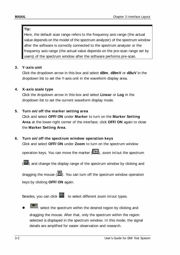
6. Turn on/off the spectrum window operation keys
Click and select OFF/ON under Zoom to turn on the spectrum window
operation keys. You can move the marker ( ), zoom in/out the spectrum
( ) and change the display range of the spectrum window by clicking and
dragging the mouse ( ). You can turn off the spectrum window operation
keys by clicking OFF/ON again.
Besides, you can click to select different zoom in/out types.
: select the spectrum within the desired region by clicking and
dragging the mouse. After that, only the spectrum within the region selected is displayed in the spectrum window. In this mode, the signal details are amplified for easier observation and research.
Chapter 3 Interface Layout RIGOL
User’s Guide for EMI Test System 3-3
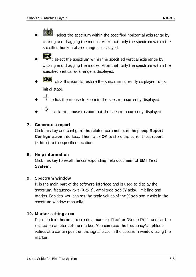
: select the spectrum within the specified horizontal axis range by
clicking and dragging the mouse. After that, only the spectrum within the specified horizontal axis range is displayed.
: select the spectrum within the specified vertical axis range by clicking and dragging the mouse. After that, only the spectrum within the specified vertical axis range is displayed.
: click this icon to restore the spectrum currently displayed to its
initial state.
: click the mouse to zoom in the spectrum currently displayed.
: click the mouse to zoom out the spectrum currently displayed.
7. Generate a report
Click this key and configure the related parameters in the popup Report Configuration interface. Then, click OK to store the current test report (*.html) to the specified location.
8. Help information
Click this key to recall the corresponding help document of EMI Test System.
9. Spectrum window
It is the main part of the software interface and is used to display the spectrum, frequency axis (X axis), amplitude axis (Y axis), limit line and marker. Besides, you can set the scale values of the X axis and Y axis in the spectrum window manually.
10. Marker setting area
Right-click in this area to create a marker ("Free" or "Single-Plot") and set the related parameters of the marker. You can read the frequency/amplitude values at a certain point on the signal trace in the spectrum window using the marker.
RIGOL Chapter 3 Interface Layout
3-4 User’s Guide for EMI Test System
11. Peak list editing keys The 8 keys (Add Peak, Insert Before, Insert After, Delete Peak, Clear Peak, Comment, Save and Load) are used to add peak values (add into the last row by default), insert peak values before the specified row, insert peak values behind the specified row, delete the specified peak value, clear all the peak values, add comments, store the current peak list and load a peak list stored. Besides, you can click the dropdown arrow in the Filter box and select the desired option to view the Pass/Fail, Pass or Fail peak results.
12. Peak search list
Display the results of peak search, including the Frequency, Level, Final Level, Limit, Delta Limit, Pass/Fail and Comment.
Chapter 4 Function Overview RIGOL
User’s Guide for EMI Test System 4-1
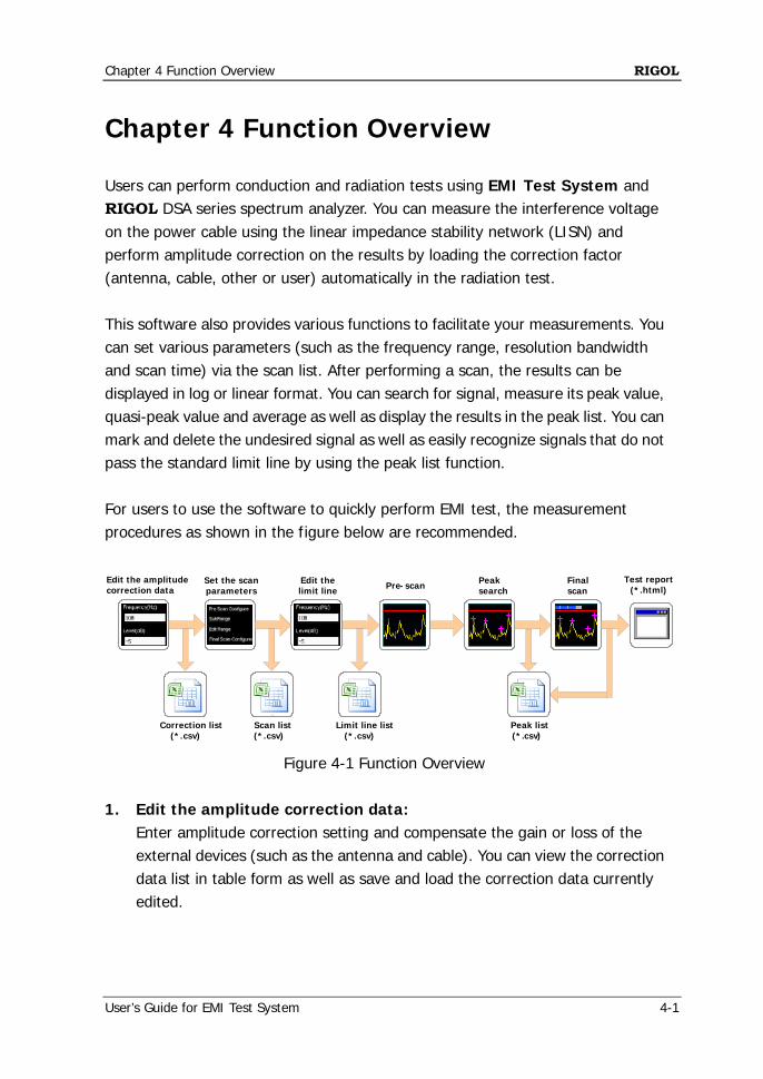
Chapter 4 Function Overview Users can perform conduction and radiation tests using EMI Test System and RIGOL DSA series spectrum analyzer. You can measure the interference voltage on the power cable using the linear impedance stability network (LISN) and perform amplitude correction on the results by loading the correction factor (antenna, cable, other or user) automatically in the radiation test. This software also provides various functions to facilitate your measurements. You can set various parameters (such as the frequency range, resolution bandwidth and scan time) via the scan list. After performing a scan, the results can be displayed in log or linear format. You can search for signal, measure its peak value, quasi-peak value and average as well as display the results in the peak list. You can mark and delete the undesired signal as well as easily recognize signals that do not pass the standard limit line by using the peak list function. For users to use the software to quickly perform EMI test, the measurement procedures as shown in the figure below are recommended.
Edit the limit line
Peak search
Final scan
Set the scan parameters
Correction list (*.csv)
Scan list (*.csv)
Pre-scan
Peak list (*.csv)
Limit line list (*.csv)
Edit the amplitude correction data
Test report(*.html)
Figure 4-1 Function Overview 1. Edit the amplitude correction data:
Enter amplitude correction setting and compensate the gain or loss of the external devices (such as the antenna and cable). You can view the correction data list in table form as well as save and load the correction data currently edited.
RIGOL Chapter 4 Function Overview
4-2 User’s Guide for EMI Test System
2. Set the scan parameters: Configure the pre-scan, segment scan and final scan parameters. You can set the segment scan parameters separately using EMI Test System, view the segment scan data list in table form as well as save and load the segment scan data currently edited.
3. Edit the limit line:
Edit the limit line data and set the measurement limits. You can view the limit line data list in table form as well as save and load the limit line data currently edited. After performing a step frequency scan, you can preview the measurement results in the spectrum window and compare them with the preset limit line value.
4. Pre-scan:
Perform segment pre-scan according to the segment scan setting to improve the measurement speed of the software.
5. Peak search:
Set the peak parameters and perform peak search. The spectrum analyzer filters and marks the peak list according to the user-defined conditions. Users can edit the peak list, add or delete frequency points as well as save and load the peak list currently edited.
6. Final scan:
One-key final scan. You can perform more accurate scan on critical interference signals using the final scan function to ensure the measurement accuracy of the software.
7. Test report:
Add report parameters and other explanations according to the actual test environment. The software generates a test report (*.html file) automatically for further processing of the measurement values.
Chapter 5 To Edit the Amplitude Correction Data RIGOL
User’s Guide for EMI Test System 5-1
Chapter 5 To Edit the Amplitude
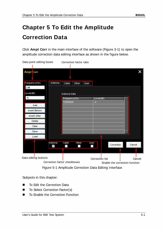
Correction Data Click Ampt Corr in the main interface of the software (Figure 3-1) to open the amplitude correction data editing interface as shown in the figure below.
Figure 5-1 Amplitude Correction Data Editing Interface
Subjects in this chapter:
To Edit the Correction Data To Select Correction Factor(s) To Enable the Correction Function
Data editing buttons
Data point editing boxes Correction factor tabs
Correction factor checkboxes Enable the correction function Cancel Correction list
RIGOL Chapter 5 To Edit the Amplitude Correction Data
5-2 User’s Guide for EMI Test System
Tip:
(1) The parameter ranges introduced in this section are related to the model of the spectrum analyzer used.
(2) When setting a parameter, the software will automatically use the limit value (upper limit value or lower limit value) and no prompt message will be displayed if the parameter set exceeds the limit value (greater than the upper limit value or lower than the lower limit value).
To Edit the Correction Data The correction data can contain at most 200 data points.
1. Edit the data point Click Frequency(Hz) in Figure 5-1 and input the desired frequency value. The default unit is "Hz". Click Level(dB) and input the desired amplitude value. The default unit is "dB".
2. Add data points
After editing the parameters (frequency and amplitude) of each data point manually, Click Add to add a group of correction data into the correction list (they
are added into the last row by default); Click Insert Before to insert a group of correction data in the row in
front of the data row currently selected; Click Insert After to insert a group of correction data in the row behind
the data row currently selected.
Tip:
You can click the Correction factor tabs to switch to the correction list corresponding to different correction factor (Antenna, Cable, Other or User) to edit or view the data points.
3. Delete data points
Select a row of data in the correction list and click Delete to delete the correction data in the specified row.
Click Clear to delete all the data in the correction list.
Chapter 5 To Edit the Amplitude Correction Data RIGOL
User’s Guide for EMI Test System 5-3
4. Save the data list Click Save to save the correction data edited in csv format.
5. Load a data list
Click Load to load a stored correction data csv file.
To Select Correction Factor(s) After editing the correction data, click the Correction factor checkboxes to select the desired correction factor(s) (Antenna, Cable, Other or User). Check the checkbox to select the corresponding correction factor. Uncheck the checkbox to unselect the corresponding correction factor.
Tip:
You can select one, more or all of Antenna, Cable, Other and User as the correction factors.
To Enable the Correction Function After selecting the desired correction factor(s), you can click Correction to enable the correction function(s) of a single, more or all of the correction factors. At this point, the status icon of the spectrum analyzer is turned on and the amplitude correction function of the analyzer is enabled.

Chapter 6 To Set the Scan Parameters RIGOL
User’s Guide for EMI Test System 6-1
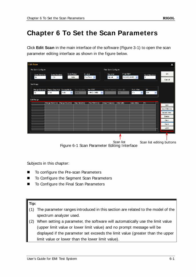
Chapter 6 To Set the Scan Parameters Click Edit Scan in the main interface of the software (Figure 3-1) to open the scan parameter editing interface as shown in the figure below.
Figure 6-1 Scan Parameter Editing Interface
Subjects in this chapter:
To configure the Pre-scan Parameters To Configure the Segment Scan Parameters To Configure the Final Scan Parameters
Tip:
(1) The parameter ranges introduced in this section are related to the model of the spectrum analyzer used.
(2) When setting a parameter, the software will automatically use the limit value (upper limit value or lower limit value) and no prompt message will be displayed if the parameter set exceeds the limit value (greater than the upper limit value or lower than the lower limit value).
Scan list Scan list editing buttons
RIGOL Chapter 6 To Set the Scan Parameters
6-2 User’s Guide for EMI Test System
To Configure the Pre-scan Parameters You can set the following parameters in Pre Scan Configure in the scan parameter editing interface (Figure 6-1). 1. Scan start frequency
Click the Scan Start(Hz) box and input the start frequency of pre-scan (for example, 9k). The default unit is Hz.
2. Scan stop frequency
Click the Scan Stop(Hz) box and input the stop frequency of pre-scan (for example, 1.5G). The default unit is Hz.
3. Scan range
Click Auto under Scan Range to set the start frequency (Scan Start) and stop frequency (Scan Stop) of the current pre-scan to the minimum and maximum of all the scan sub-ranges added (Add) into the Scan List. Note: Before using Auto, you need to add (Add) the scan sub-ranges into the Scan List. The sub-ranges cannot overlap. The scan sub-range is defined by Range Start(Hz) and Range Stop(Hz).
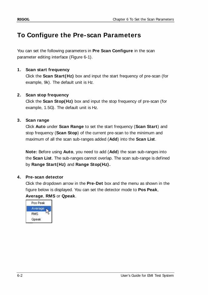
4. Pre-scan detector Click the dropdown arrow in the Pre-Det box and the menu as shown in the figure below is displayed. You can set the detector mode to Pos Peak, Average, RMS or Qpeak.
Chapter 6 To Set the Scan Parameters RIGOL
User’s Guide for EMI Test System 6-3
To Configure the Segment Scan Parameters To Set the Scan Sub-range Parameters You can set the following parameters in SubRange in the scan parameter editing interface (Figure 6-1). 1. Sub-range start frequency
Click the Range Start(Hz) box and input the desired start frequency of the sub-range. The default unit is Hz.
2. Sub-range stop frequency
Click the Range Stop(Hz) box and input the desired stop frequency of the sub-range. The default unit is Hz.
3. Scan mode
Click the dropdown arrow in the Sweep Mode box to set the scan mode within the scan sub-range currently selected to Auto or Manual. When Auto is selected, the Step Size(Hz) and Meas Time(ms) boxes
are grayed out and disabled. When the pre-scan resolution bandwidth (Pre-RBW) is set to different value, Step Size(Hz) uses the corresponding default value.
When Manual is selected, you can set the Step Size(Hz) and Meas Time(ms) manually. For the setting methods, refer to the setting of Sub-range start frequency.
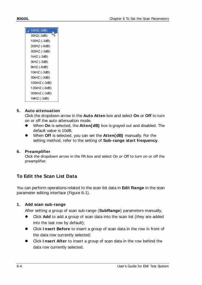
4. Pre-scan resolution bandwidth
Click the Pre-RBW box and the menu as shown below is displayed. You can set the current scan resolution bandwidth to 10Hz (-3dB), 30Hz (-3dB), 100Hz (-3dB), 200Hz (-6dB), 300Hz (-3dB), 1kHz (-3dB), 3kHz (-3dB), 9kHz (-6dB), 10kHz (-3dB), 30kHz (-3dB), 100kHz (-3dB), 120kHz (-6dB), 300kHz (-3dB) or 1MHz (-3dB). When the pre-scan detector (Pre-Det) is set to "Qpeak", only 200Hz (-6dB), 9kHz (-6dB) and 120kHz (-6dB) are available.
RIGOL Chapter 6 To Set the Scan Parameters
6-4 User’s Guide for EMI Test System
5. Auto attenuation
Click the dropdown arrow in the Auto Atten box and select On or Off to turn on or off the auto attenuation mode. When On is selected, the Atten(dB) box is grayed out and disabled. The
default value is 10dB. When Off is selected, you can set the Atten(dB) manually. For the
setting method, refer to the setting of Sub-range start frequency. 6. Preamplifier
Click the dropdown arrow in the PA box and select On or Off to turn on or off the preamplifier.
To Edit the Scan List Data You can perform operations related to the scan list data in Edit Range in the scan parameter editing interface (Figure 6-1). 1. Add scan sub-range
After setting a group of scan sub-range (SubRange) parameters manually, Click Add to add a group of scan data into the scan list (they are added
into the last row by default); Click Insert Before to insert a group of scan data in the row in front of
the data row currently selected; Click Insert After to insert a group of scan data in the row behind the
data row currently selected.
Chapter 6 To Set the Scan Parameters RIGOL
User’s Guide for EMI Test System 6-5
Note: When adding the scan sub-ranges, the sub-ranges cannot overlap. Otherwise, "Subrange is repeat. Please change the range." will be displayed.
2. Delete data points
Select a row of data in the scan list and click Delete to delete the scan data in the specified row.
Click Clear to delete all the data in the scan list. 3. Save the data list
Click Save to save the scan data edited in csv format. 4. Load a scan list
Click Load to load a stored scan data csv file.
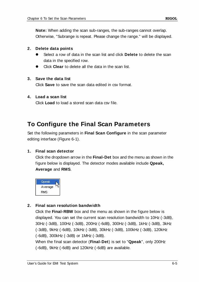
To Configure the Final Scan Parameters Set the following parameters in Final Scan Configure in the scan parameter editing interface (Figure 6-1). 1. Final scan detector
Click the dropdown arrow in the Final-Det box and the menu as shown in the figure below is displayed. The detector modes available include Qpeak, Average and RMS.
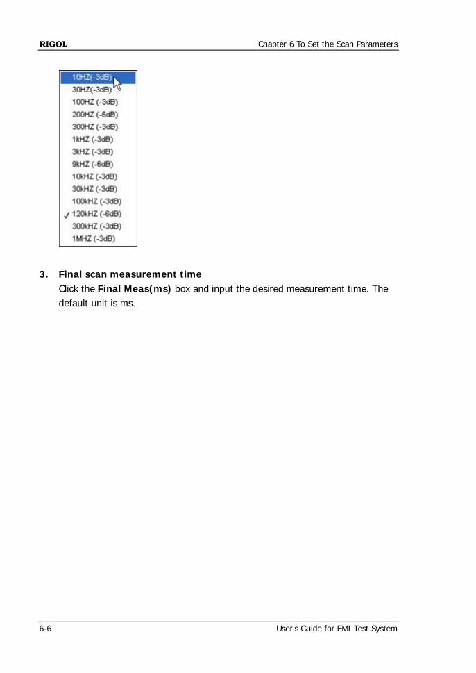
2. Final scan resolution bandwidth Click the Final-RBW box and the menu as shown in the figure below is displayed. You can set the current scan resolution bandwidth to 10Hz (-3dB), 30Hz (-3dB), 100Hz (-3dB), 200Hz (-6dB), 300Hz (-3dB), 1kHz (-3dB), 3kHz (-3dB), 9kHz (-6dB), 10kHz (-3dB), 30kHz (-3dB), 100kHz (-3dB), 120kHz (-6dB), 300kHz (-3dB) or 1MHz (-3dB). When the final scan detector (Final-Det) is set to "Qpeak", only 200Hz (-6dB), 9kHz (-6dB) and 120kHz (-6dB) are available.
RIGOL Chapter 6 To Set the Scan Parameters
6-6 User’s Guide for EMI Test System
3. Final scan measurement time
Click the Final Meas(ms) box and input the desired measurement time. The default unit is ms.
Chapter 7 To Edit the Limit Line RIGOL
User’s Guide for EMI Test System 7-1
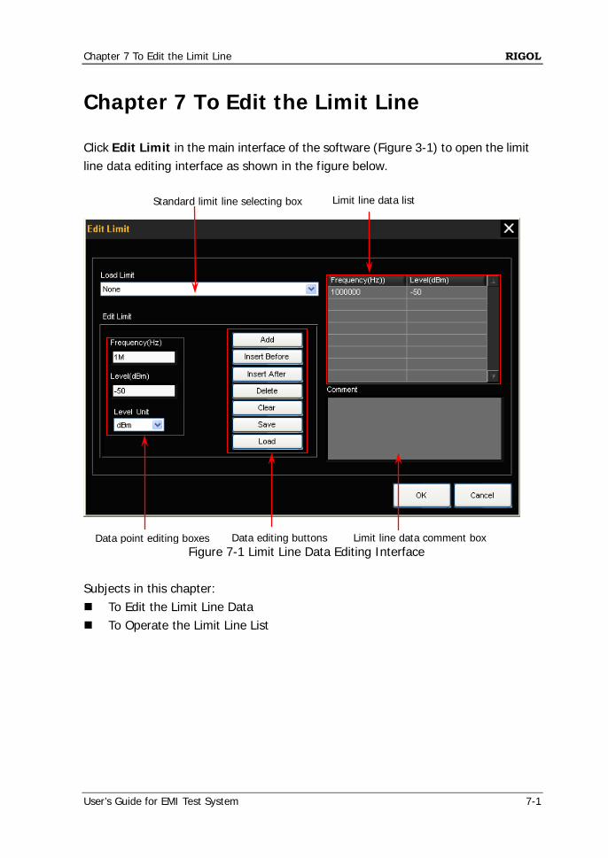
Chapter 7 To Edit the Limit Line Click Edit Limit in the main interface of the software (Figure 3-1) to open the limit line data editing interface as shown in the figure below.
Figure 7-1 Limit Line Data Editing Interface
Subjects in this chapter: To Edit the Limit Line Data To Operate the Limit Line List
Standard limit line selecting box
Data editing buttons
Limit line data list
Data point editing boxes Limit line data comment box
RIGOL Chapter 7 To Edit the Limit Line
7-2 User’s Guide for EMI Test System
Tip:
(1) After the limit line is edited, the limit curve is displayed in the main interface of the software.
(2) In addition, if the amplitude measured of a frequency point in the spectrum of the signal under measurement is lower than the limit line amplitude, the signal passes the test; if the amplitude measured of a frequency point is greater than the limit line amplitude, the test fails.
(3) The parameter ranges introduced in this section are related to the model of the spectrum analyzer used.
(4) When setting a parameter, the software will automatically use the limit value (upper limit value or lower limit value) and no prompt message will be displayed if the parameter set exceeds the limit value (greater than the upper limit value or lower than the lower limit value).
To Edit the Limit Line Data 1. Load the standard limit line
Click the Standard limit line selecting box (Load Limit) in Figure 7-1 and select the desired standard limit line (the default is "User") in the popup menu. At this point, the Limit line data list displays the data of the standard limit line currently selected and the Limit line data comment box displays the corresponding comment information.
2. Edit the data points of the limit line manually
Click the Frequency(Hz) box in Figure 7-1 and input the desired frequency. The default unit is Hz. Click the Level(dBm) box and input the desired amplitude. The default unit is dBm.
Chapter 7 To Edit the Limit Line RIGOL
User’s Guide for EMI Test System 7-3
To Operate the Limit Line List 1. Add data points
After editing the parameters (frequency and amplitude) of each data point manually in Figure 7-1. Click Add to add a group of limit line data into the limit line list (they are
added into the last row by default); Click Insert Before to insert a group of limit line data in the row in front
of the data row currently selected; Click Insert After to insert a group of limit line data in the row behind
the data row currently selected. 2. Delete data points
Select a row of data in the limit line list and click Delete to delete the limit line data in the specified row. Clear to delete all the data in the limit line list.
3. Save the data list
Click Save to save the limit line data edited in csv format. 4. Load a data list
Click Load to load a stored limit line data csv file.
Tip: You can add the comment information manually after editing the limit line list.

Chapter 8 To Perform Pre-scan RIGOL
User’s Guide for EMI Test System 8-1
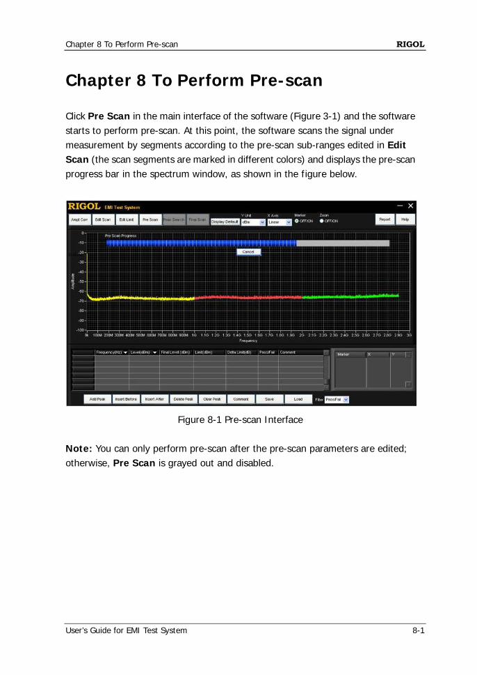
Chapter 8 To Perform Pre-scan Click Pre Scan in the main interface of the software (Figure 3-1) and the software starts to perform pre-scan. At this point, the software scans the signal under measurement by segments according to the pre-scan sub-ranges edited in Edit Scan (the scan segments are marked in different colors) and displays the pre-scan progress bar in the spectrum window, as shown in the figure below.
Figure 8-1 Pre-scan Interface Note: You can only perform pre-scan after the pre-scan parameters are edited; otherwise, Pre Scan is grayed out and disabled.

Chapter 9 To Perform Peak Search RIGOL
User’s Guide for EMI Test System 9-1
Chapter 9 To Perform Peak Search This section introduces how to perform peak search as well as how to edit and operate the peak search list using EMI Test System. Subjects in this chapter: To Set the Peak Search Parameters To Edit the Peak Search List To Operate the Peak Search List
RIGOL Chapter 9 To Perform Peak Search
9-2 User’s Guide for EMI Test System
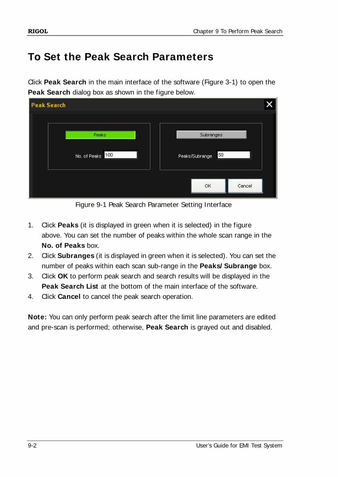
To Set the Peak Search Parameters Click Peak Search in the main interface of the software (Figure 3-1) to open the Peak Search dialog box as shown in the figure below.
Figure 9-1 Peak Search Parameter Setting Interface 1. Click Peaks (it is displayed in green when it is selected) in the figure
above. You can set the number of peaks within the whole scan range in the No. of Peaks box.
2. Click Subranges (it is displayed in green when it is selected). You can set the number of peaks within each scan sub-range in the Peaks/Subrange box.
3. Click OK to perform peak search and search results will be displayed in the Peak Search List at the bottom of the main interface of the software.
4. Click Cancel to cancel the peak search operation. Note: You can only perform peak search after the limit line parameters are edited and pre-scan is performed; otherwise, Peak Search is grayed out and disabled.
Chapter 9 To Perform Peak Search RIGOL
User’s Guide for EMI Test System 9-3
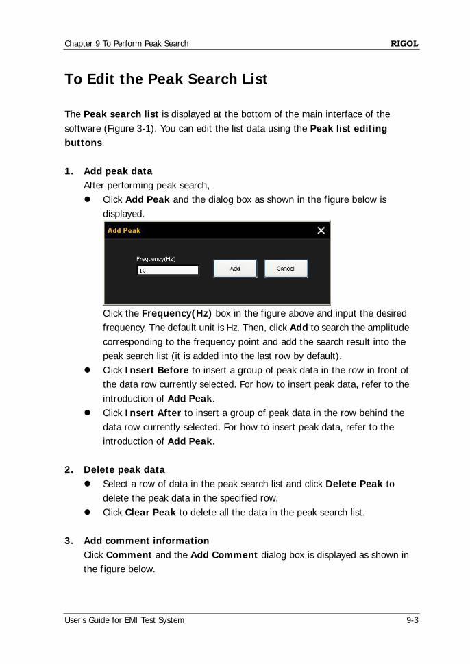
To Edit the Peak Search List The Peak search list is displayed at the bottom of the main interface of the software (Figure 3-1). You can edit the list data using the Peak list editing buttons. 1. Add peak data
After performing peak search, Click Add Peak and the dialog box as shown in the figure below is
displayed.
Click the Frequency(Hz) box in the figure above and input the desired frequency. The default unit is Hz. Then, click Add to search the amplitude corresponding to the frequency point and add the search result into the peak search list (it is added into the last row by default).
Click Insert Before to insert a group of peak data in the row in front of the data row currently selected. For how to insert peak data, refer to the introduction of Add Peak.
Click Insert After to insert a group of peak data in the row behind the data row currently selected. For how to insert peak data, refer to the introduction of Add Peak.
2. Delete peak data
Select a row of data in the peak search list and click Delete Peak to delete the peak data in the specified row.
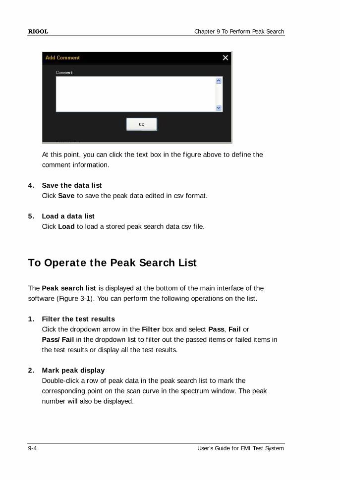
Click Clear Peak to delete all the data in the peak search list. 3. Add comment information
Click Comment and the Add Comment dialog box is displayed as shown in the figure below.
RIGOL Chapter 9 To Perform Peak Search
9-4 User’s Guide for EMI Test System
At this point, you can click the text box in the figure above to define the comment information.
4. Save the data list
Click Save to save the peak data edited in csv format. 5. Load a data list
Click Load to load a stored peak search data csv file.
To Operate the Peak Search List The Peak search list is displayed at the bottom of the main interface of the software (Figure 3-1). You can perform the following operations on the list. 1. Filter the test results
Click the dropdown arrow in the Filter box and select Pass, Fail or Pass/Fail in the dropdown list to filter out the passed items or failed items in the test results or display all the test results.
2. Mark peak display
Double-click a row of peak data in the peak search list to mark the corresponding point on the scan curve in the spectrum window. The peak number will also be displayed.
Chapter 9 To Perform Peak Search RIGOL
User’s Guide for EMI Test System 9-5
3. Peak data ordering Click at the right of Frequency(Hz) or Level(dBm) in the peak search list to order the peak data according to the frequency values. Click . The peak data are displayed from large to small according to
their frequency values by default. Click again. The peak data are displayed from small to large
according to their frequency values.

Chapter 10 To Perform Final Scan RIGOL
User’s Guide for EMI Test System 10-1
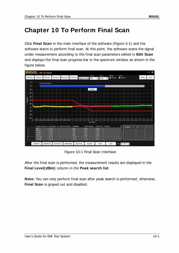
Chapter 10 To Perform Final Scan Click Final Scan in the main interface of the software (Figure 3-1) and the software starts to perform final scan. At this point, the software scans the signal under measurement according to the final scan parameters edited in Edit Scan and displays the final scan progress bar in the spectrum window as shown in the figure below.
Figure 10-1 Final Scan Interface After the final scan is performed, the measurement results are displayed in the Final Level(dBm) column in the Peak search list. Note: You can only perform final scan after peak search is performed; otherwise, Final Scan is grayed out and disabled.

Chapter 11 To Generate a Test Report RIGOL
User’s Guide for EMI Test System 11-1
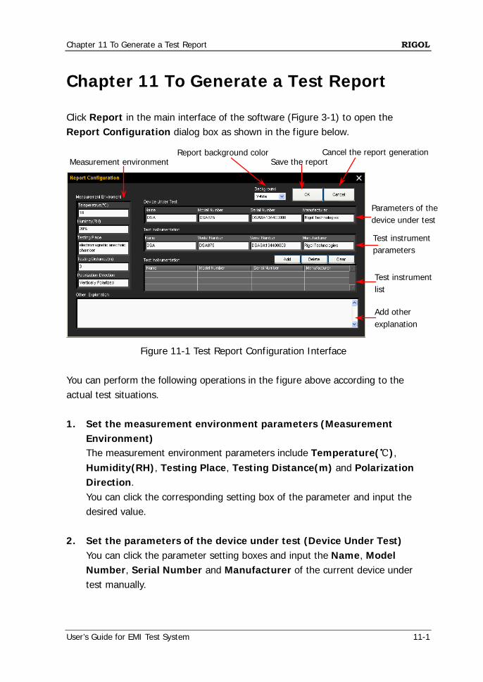
Chapter 11 To Generate a Test Report Click Report in the main interface of the software (Figure 3-1) to open the Report Configuration dialog box as shown in the figure below.
Figure 11-1 Test Report Configuration Interface
You can perform the following operations in the figure above according to the actual test situations. 1. Set the measurement environment parameters (Measurement
Environment) The measurement environment parameters include Temperature(℃), Humidity(RH), Testing Place, Testing Distance(m) and Polarization Direction. You can click the corresponding setting box of the parameter and input the desired value.
2. Set the parameters of the device under test (Device Under Test)
You can click the parameter setting boxes and input the Name, Model Number, Serial Number and Manufacturer of the current device under test manually.
Measurement environment
Report background color Save the report
Cancel the report generation
Test instrument list
Test instrument parameters
Parameters of the device under test
Add other explanation
RIGOL Chapter 11 To Generate a Test Report
11-2 User’s Guide for EMI Test System
3. Configure the parameters of the test instrument (Test Instrumentation) The test instrument currently detected is displayed by default (the instrument is connect to the PC installed with EMI Test System via the communication interface). In addition, you can input the other parameters of the test instrument required by the current test manually and add them into the test instrument list.
4. Edit the test instrument list
After editing a group of test instrument parameters, Click Add to add the test instrument parameters currently edited into the
test instrument list (multiple groups of test instrument data can be added);
Select a row of data in the test instrument list and click Delete to delete this group of test instrument data;
Click Clear to clear all the data in the test instrument list. 5. Add other explanation (Other Explanation)
You can click the text box under Other Explanation to define other information in the test report.
6. Select the background color of the trace display (Background)
Click the Background box and select White or Black in the dropdown list to set the background color of the trace display (Traces Display) in the test report to be saved to "White" or "Black".
7. Save the report
After configuring all the report parameters, you can click OK to save the current test report in *.html format. The report includes the Measurement Time, Measurement Environment, Device Under Test, Test Instrumentation, Instrument Setting, Previous Detector, Final Detector, Final RBW, Final Meas Time, Limit Data, Traces Display, Peaks List and Other Explanation.
8. Cancel the report generation
You can click Cancel to cancel the current report generation operation and exit the test report configuration interface.
Chapter 12 Specifications RIGOL
User’s Guide for EMI Test System 12-1
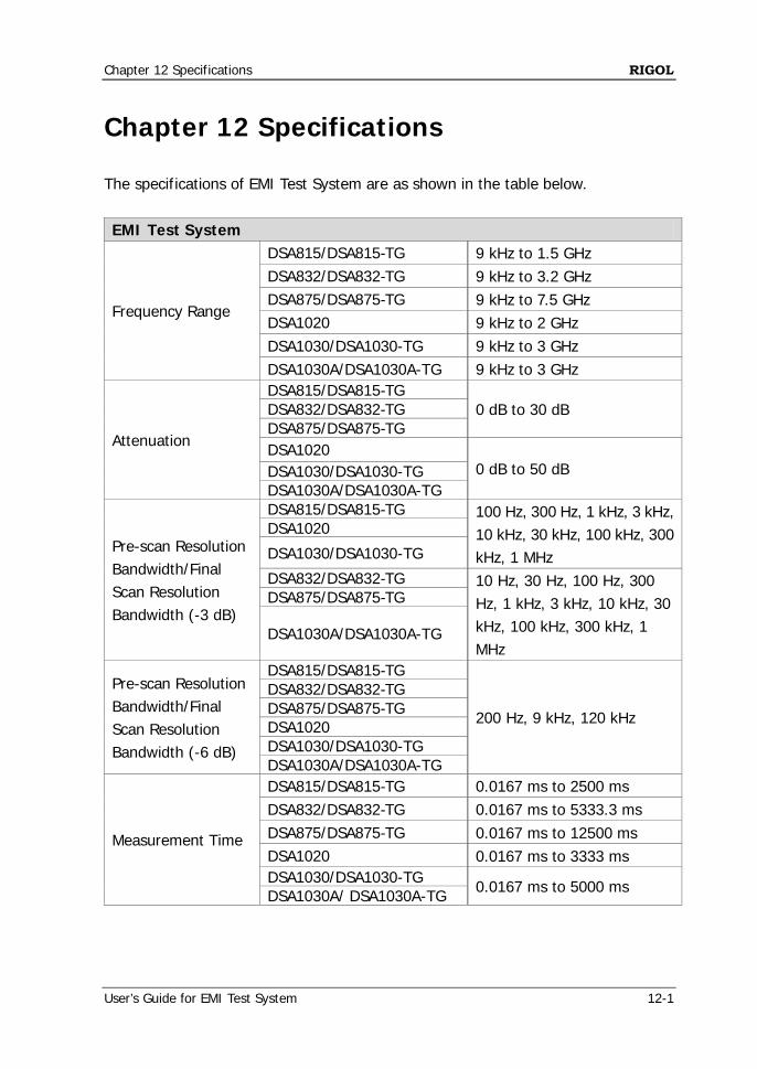
Chapter 12 Specifications The specifications of EMI Test System are as shown in the table below. EMI Test System
Frequency Range
DSA815/DSA815-TG 9 kHz to 1.5 GHz DSA832/DSA832-TG 9 kHz to 3.2 GHz DSA875/DSA875-TG 9 kHz to 7.5 GHz DSA1020 9 kHz to 2 GHz DSA1030/DSA1030-TG 9 kHz to 3 GHz DSA1030A/DSA1030A-TG 9 kHz to 3 GHz
Attenuation
DSA815/DSA815-TG 0 dB to 30 dB DSA832/DSA832-TG
DSA875/DSA875-TG DSA1020
0 dB to 50 dB DSA1030/DSA1030-TG DSA1030A/DSA1030A-TG
Pre-scan Resolution Bandwidth/Final Scan Resolution Bandwidth (-3 dB)
DSA815/DSA815-TG 100 Hz, 300 Hz, 1 kHz, 3 kHz, 10 kHz, 30 kHz, 100 kHz, 300 kHz, 1 MHz
DSA1020
DSA1030/DSA1030-TG
DSA832/DSA832-TG 10 Hz, 30 Hz, 100 Hz, 300 Hz, 1 kHz, 3 kHz, 10 kHz, 30 kHz, 100 kHz, 300 kHz, 1 MHz
DSA875/DSA875-TG
DSA1030A/DSA1030A-TG
Pre-scan Resolution Bandwidth/Final Scan Resolution Bandwidth (-6 dB)
DSA815/DSA815-TG
200 Hz, 9 kHz, 120 kHz
DSA832/DSA832-TG DSA875/DSA875-TG DSA1020 DSA1030/DSA1030-TG DSA1030A/DSA1030A-TG
Measurement Time
DSA815/DSA815-TG 0.0167 ms to 2500 ms DSA832/DSA832-TG 0.0167 ms to 5333.3 ms DSA875/DSA875-TG 0.0167 ms to 12500 ms DSA1020 0.0167 ms to 3333 ms DSA1030/DSA1030-TG 0.0167 ms to 5000 ms DSA1030A/ DSA1030A-TG

Chapter 13 Appendix RIGOL
User’s Guide for EMI Test System 13-1
Chapter 13 Appendix
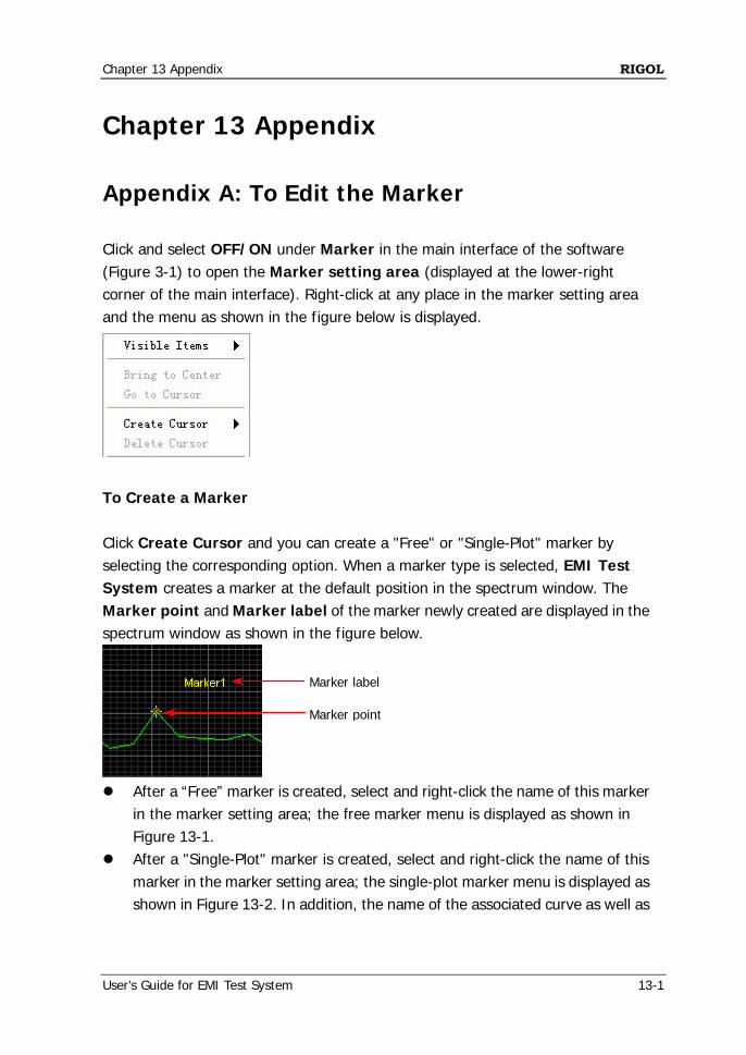
Appendix A: To Edit the Marker Click and select OFF/ON under Marker in the main interface of the software (Figure 3-1) to open the Marker setting area (displayed at the lower-right corner of the main interface). Right-click at any place in the marker setting area and the menu as shown in the figure below is displayed.
To Create a Marker Click Create Cursor and you can create a "Free" or "Single-Plot" marker by selecting the corresponding option. When a marker type is selected, EMI Test System creates a marker at the default position in the spectrum window. The Marker point and Marker label of the marker newly created are displayed in the spectrum window as shown in the figure below.
After a “Free” marker is created, select and right-click the name of this marker
in the marker setting area; the free marker menu is displayed as shown in Figure 13-1.
After a "Single-Plot" marker is created, select and right-click the name of this marker in the marker setting area; the single-plot marker menu is displayed as shown in Figure 13-2. In addition, the name of the associated curve as well as
Marker point
Marker label
RIGOL Chapter 13 Appendix
13-2 User’s Guide for EMI Test System
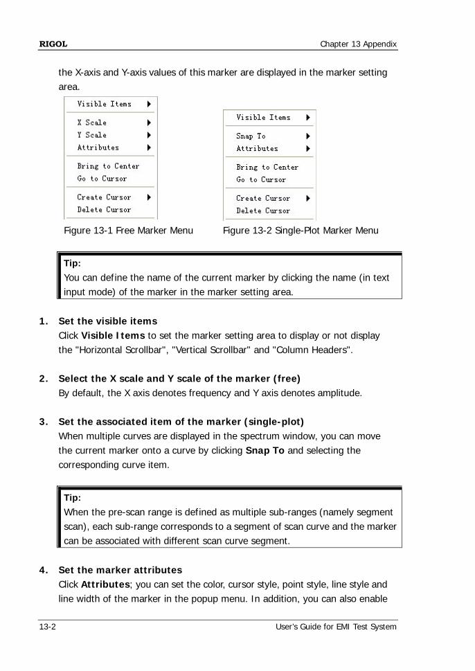
the X-axis and Y-axis values of this marker are displayed in the marker setting area.
Figure 13-1 Free Marker Menu Figure 13-2 Single-Plot Marker Menu
Tip:
You can define the name of the current marker by clicking the name (in text input mode) of the marker in the marker setting area.
1. Set the visible items
Click Visible Items to set the marker setting area to display or not display the "Horizontal Scrollbar", "Vertical Scrollbar" and "Column Headers".
2. Select the X scale and Y scale of the marker (free)
By default, the X axis denotes frequency and Y axis denotes amplitude. 3. Set the associated item of the marker (single-plot)
When multiple curves are displayed in the spectrum window, you can move the current marker onto a curve by clicking Snap To and selecting the corresponding curve item.
Tip:
When the pre-scan range is defined as multiple sub-ranges (namely segment scan), each sub-range corresponds to a segment of scan curve and the marker can be associated with different scan curve segment.
4. Set the marker attributes
Click Attributes; you can set the color, cursor style, point style, line style and line width of the marker in the popup menu. In addition, you can also enable
Chapter 13 Appendix RIGOL
User’s Guide for EMI Test System 13-3
or disable the display of the marker name by checking or unchecking Show Name (it is checked by default).
5. Move the marker
Click Bring to Center; the marker will be moved to the center of the current curve segment without changing the X-axis and Y-axis scales.
Click Go to Cursor; the marker will be moved to the center of the current spectrum window and the X-axis and Y-axis scales will be changed.
Besides, you can drag the marker to the desired position in the spectrum window.
Note: When the pre-scan range is defined as multiple sub-ranges (namely segment scan), the marker can only move on the current associated curve segment.
6. Delete a marker
Click Delete Cursor to delete the marker currently selected.
RIGOL Chapter 13 Appendix
13-4 User’s Guide for EMI Test System
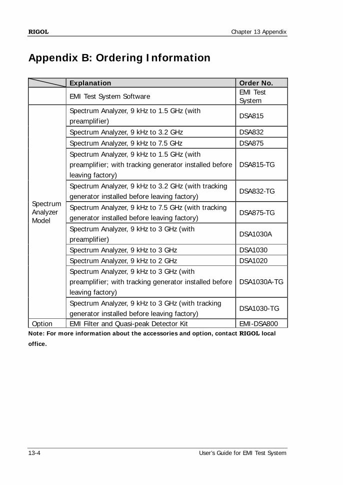
Appendix B: Ordering Information Explanation Order No.
EMI Test System Software EMI Test System
Spectrum Analyzer Model
Spectrum Analyzer, 9 kHz to 1.5 GHz (with preamplifier)
DSA815
Spectrum Analyzer, 9 kHz to 3.2 GHz DSA832
Spectrum Analyzer, 9 kHz to 7.5 GHz DSA875
Spectrum Analyzer, 9 kHz to 1.5 GHz (with preamplifier; with tracking generator installed before leaving factory)
DSA815-TG
Spectrum Analyzer, 9 kHz to 3.2 GHz (with tracking generator installed before leaving factory)
DSA832-TG
Spectrum Analyzer, 9 kHz to 7.5 GHz (with tracking generator installed before leaving factory)
DSA875-TG
Spectrum Analyzer, 9 kHz to 3 GHz (with preamplifier)
DSA1030A
Spectrum Analyzer, 9 kHz to 3 GHz DSA1030 Spectrum Analyzer, 9 kHz to 2 GHz DSA1020 Spectrum Analyzer, 9 kHz to 3 GHz (with preamplifier; with tracking generator installed before leaving factory)
DSA1030A-TG
Spectrum Analyzer, 9 kHz to 3 GHz (with tracking generator installed before leaving factory)
DSA1030-TG
Option EMI Filter and Quasi-peak Detector Kit EMI-DSA800 Note: For more information about the accessories and option, contact RIGOL local
office.
Chapter 13 Appendix RIGOL
User’s Guide for EMI Test System 13-5
Appendix C: Warranty RIGOL warrants that its products mainframe and accessories will be free from defects in materials and workmanship within the warranty period. If a product is proven to be defective within the respective period, RIGOL guarantees the free replacement or repair of products which are approved defective. To get repair service, please contact with your nearest RIGOL sales and service office. RIGOL does not provide any other warranty items except the one being provided by this summary and the warranty statement. The warranty items include but not being subjected to the hint guarantee items related to tradable characteristic and any particular purpose. RIGOL will not take any responsibility in cases regarding to indirect, particular and ensuing damage.
Related Documents