1 Copyright © 2014 by ASME Proceedings of the ASME 2014 International Design Engineering Technical Conferences & Computers and Information in Engineering Conference IDETC/CIE 2014 August 17-20, 2014, Buffalo, New York, USA DETC2014-35304 RIGID OBJECT TRACKING ALGORITHMS FOR LOW-COST AR DEVICES Timothy Garrett Virtual Reality Applications Center Iowa State University Ames, IA, USA [email protected] Saverio Debernardis Dept. of Mechanics, Mathematics and Management Politecnico di Bari Bari, Italy [email protected] Rafael Radkowski Virtual Reality Applications Center Iowa State University Ames, IA, USA [email protected] Carl K. Chang Dept. of Computer Science Iowa State University Ames, IA, USA [email protected] Michele Fiorentino Dept. of Mechanics, Mathematics and Management Politecnico di Bari Bari, Italy [email protected] Antonio E. Uva Dept. of Mechanics, Mathematics and Management Politecnico di Bari Bari, Italy [email protected] James Oliver Virtual Reality Applications Center Iowa State University Ames, IA, USA [email protected] ABSTRACT Augmented reality (AR) applications rely on robust and efficient methods for tracking. Tracking methods use a computer- internal representation of the object to track, which can be either sparse or dense representations. Sparse representations use only a limited set of feature points to represent an object to track, whereas dense representations almost mimic the shape of an object. While algorithms performed on sparse representations are faster, dense representations can distinguish multiple objects. The research presented in this paper investigates the feasibility of a dense tracking method for rigid object tracking, which incorporates the both object identification and object tracking steps. We adopted a tracking method that has been developed for the Microsoft Kinect to support single object tracking. The paper describes this method and presents the results. We also compared two different methods for mesh reconstruction in this algorithm. Since meshes are more informative when identifying a rigid object, this comparison indicates which algorithm shows the best performance for this task and guides our future research efforts. INTRODUCTION Augmented reality (AR) technology is a type of human- computer interaction that superimposes the natural visual perception of a human user with computer-generated information (i.e., 3D models, annotation, and text) [1]. AR presents this information in a context-sensitive way that is appropriate for a specific task, and typically, relative to the user’s physical location. The general approach to realize AR is to merge the physical and virtual worlds by exploiting rapid video processing, precise tracking, and computer graphics. In a typical AR system a video camera is used to capture the physical world. Then, rather than presenting the raw video to the user, the system composites the video image with computer generated images of virtual objects in positions. The effect, from a user's point of view, is a representation of the physical world that has been "augmented" with virtual objects. Augmented Reality relies on object tracking in order to achieve proper augmentation. The term object tracking refers to all techniques and methods that are appropriate to identify and register a physical object in the environment. Several techniques have been introduced, ranging from fiducial marker tracking [2] to natural feature tracking (NFT) [3,4], and 3D model tracking [5]. All the known methods work well in particular fields and have advantages in different use cases. Our research addresses the field of AR-based assembly assistance and maintenance on the factory floor. In this case, the deployed tracking technology must also be able to identify a particular mechanical part and distinguish it from several other parts. We are convinced that only 3D model tracking methods facilitates this task. Approaches such as NFT or point clouds belong to the group of sparse representation models, which, for instance, use a sparse feature map to represent an object's characteristic features. If a sparse representation is well designed, it is possible to distinguish several rigid objects [6]. 3D DRAFT

Welcome message from author
This document is posted to help you gain knowledge. Please leave a comment to let me know what you think about it! Share it to your friends and learn new things together.
Transcript
1 Copyright © 2014 by ASME
Proceedings of the ASME 2014 International Design Engineering Technical Conferences & Computers and Information in Engineering Conference
IDETC/CIE 2014 August 17-20, 2014, Buffalo, New York, USA
DETC2014-35304
RIGID OBJECT TRACKING ALGORITHMS FOR LOW-COST AR DEVICES
Timothy Garrett Virtual Reality Applications Center
Iowa State University Ames, IA, USA
Saverio Debernardis Dept. of Mechanics, Mathematics and
Management Politecnico di Bari
Bari, Italy [email protected]
Rafael Radkowski Virtual Reality Applications Center
Iowa State University Ames, IA, USA
Carl K. Chang Dept. of Computer Science
Iowa State University Ames, IA, USA
Michele Fiorentino Dept. of Mechanics,
Mathematics and Management Politecnico di Bari
Bari, Italy [email protected]
Antonio E. Uva Dept. of Mechanics,
Mathematics and Management Politecnico di Bari
Bari, Italy [email protected]
James Oliver Virtual Reality Applications
Center Iowa State University
Ames, IA, USA [email protected]
ABSTRACT Augmented reality (AR) applications rely on robust and
efficient methods for tracking. Tracking methods use a computer-internal representation of the object to track, which can be either sparse or dense representations. Sparse representations use only a limited set of feature points to represent an object to track, whereas dense representations almost mimic the shape of an object. While algorithms performed on sparse representations are faster, dense representations can distinguish multiple objects. The research presented in this paper investigates the feasibility of a dense tracking method for rigid object tracking, which incorporates the both object identification and object tracking steps. We adopted a tracking method that has been developed for the Microsoft Kinect to support single object tracking. The paper describes this method and presents the results. We also compared two different methods for mesh reconstruction in this algorithm. Since meshes are more informative when identifying a rigid object, this comparison indicates which algorithm shows the best performance for this task and guides our future research efforts.
INTRODUCTION Augmented reality (AR) technology is a type of human-computer interaction that superimposes the natural visual perception of a human user with computer-generated information (i.e., 3D models, annotation, and text) [1]. AR presents this information in a context-sensitive way that is appropriate for a specific task, and typically, relative to the user’s
physical location. The general approach to realize AR is to merge the physical and virtual worlds by exploiting rapid video processing, precise tracking, and computer graphics. In a typical AR system a video camera is used to capture the physical world. Then, rather than presenting the raw video to the user, the system composites the video image with computer generated images of virtual objects in positions. The effect, from a user's point of view, is a representation of the physical world that has been "augmented" with virtual objects. Augmented Reality relies on object tracking in order to achieve proper augmentation. The term object tracking refers to all techniques and methods that are appropriate to identify and register a physical object in the environment. Several techniques have been introduced, ranging from fiducial marker tracking [2] to natural feature tracking (NFT) [3,4], and 3D model tracking [5]. All the known methods work well in particular fields and have advantages in different use cases. Our research addresses the field of AR-based assembly assistance and maintenance on the factory floor. In this case, the deployed tracking technology must also be able to identify a particular mechanical part and distinguish it from several other parts. We are convinced that only 3D model tracking methods facilitates this task. Approaches such as NFT or point clouds belong to the group of sparse representation models, which, for instance, use a sparse feature map to represent an object's characteristic features. If a sparse representation is well designed, it is possible to distinguish several rigid objects [6]. 3D
DRAFT
2 Copyright © 2014 by ASME
model tracking usually belongs to a group of dense representation models, which use a dense 3D model to track, map, and identify a particular rigid object. Several approaches have been introduced [7,8]. However, they have been designed to generate an accurate 3D model of the environment and to calculate a camera pose rather than to track a particular rigid object. In our research, we investigated a dense representation approach and analyzed its feasibility to track and identify a particular rigid object for AR. Our research relies on the KinectFusion algorithm [7], which provides functionality to track a camera’s pose. Instead of tracking the camera’s pose, the tracker has been extended to track and identify rigid objects. The Microsoft Kinect is used to generate a 3D model of the environment. This generated model is matched against a reference model in order to track it. Additionally, we compared two different mesh generation methods and measured the runtime and the matching results (true-positives / false-positives). The results are promising and show feasibility of our approach. However, the performance still needs to be improved for AR. The paper is structured as follows. In the next section, we present the related work. Section 3 explains our tracking approach and introduces the methods. In Section 4, we describe the comparison, the methods we compared, and present the results. The paper closes in Section 5 with a summary and an outlook.
RELATED WORK Tracking a rigid 3D object means continuously identifying
the location and orientation of an object. Many approaches for tracking exist. Some approaches are fiducial marker tracking, natural feature tracking, and 3D object tracking. In this review, we address the fields of natural feature tracking and 3D object tracking.
Natural Feature Tracking Natural feature tracking considers interesting points unique
to an object as natural landmarks to track. Vacchetti et al. [9] use interest points from the standard Harris corners algorithm [10] based on pixel gradients for object recognition and real-time tracking.
Kim et al. [11] use planar interest points for object recognition as well, however, Zernike moments are used to represent local image segments and matched to a database object with a probabilistic voting scheme. Once an object is recognized, it is tracked with Lie group methodologies.
In [12], Haag and Nagel combine edge elements and optical flow with a Kalman filter to recognize and track objects in traffic sequences from a database of models, opting for robustness over real-time performance. Since tracking by optical flow requires objects to move, the contribution of optical flow to pose estimation gradually fades away as movement is decreased.
Lepetit et al. [13] introduce a keypoint-based tracking method that automatically builds different view sets of a training image in order to improve performance and robustness. Multiple keypoints are extracted from these images and stored as a classification database. They use a randomized kd-tree to
classify the feature points of a sample image. This method works robustly, facilitates tracking of a wide range of images, and copes with cluttered and distorted objects. Nevertheless, this approach is trained for only tracking one object.
Chen et al. [3] demonstrate a keypoint tracking system that copes with different lighting conditions. The authors employ a FAST algorithm to extract keypoint features and descriptors. The descriptors are organized in a kd-tree for fast keypoint retrieval. To improve the robustness, a Kanade-Lucas-Tomasi (KLT) tracker [15] is added that delivers additional information for pose estimation. This enhances the probability of obtaining good features to track. The method utilizes an additional matching algorithm to improve robustness. Yet, their method is not able to distinguish different objects.
Cagalaban et al. [16] introduce a tracking method that allows tracking of multiple 3D objects in unprepared environments. Their method incorporates KLT tracking and color tracking to detect multiple moving objects. However, the authors' test objects were relatively simple (cars), object segmentation relies on background separation, and the tracked objects cannot be identified.
Uchiyama et al. [17] present a tracking method that relies on a method called locally likely arrangement hashing. The authors intend to track 2D maps, which are difficult to track because the arrangement of a map looks similar from different viewpoints. Their tracking approach utilizes the intersections on maps to retrieve a robust feature map. In addition, the authors use online learning to be able to cover a large map.
Gruber et al. [4] conduct research in keypoint optimization and keypoint selection in order to optimize the keypoint database in such a way that only the best and most robust features are used for tracking. For instance, they explore the effect of different texture characteristics on tracking.
Rusu et al. [19] use natural features for real-time 3D object and pose recognition using their robot with stereo cameras. Planes are identified from point cloud surface normal estimation and segmented out. A Viewpoint Feature Histogram (extended from the Fast Point Feature Histogram [10]) is calculated for each segmentation based on relative angle directions of surface normals.
In summary, several methods exists which facilitate the tracking of physical objects. However, feature tracking approaches usually rely on a sparse feature model of the object to track, which is aligned with features that can be obtained at runtime to identify and track the object.
3D Camera and Object Tracking The term 3D object tracking refers to all methods that use a
dense representation of an object to track as computer-internal representation. In most cases, this type of tracking requires sifting through a large amount of 3D data points to align a reference model with an object to track.
Newcombe et al. [7] introduce KinectFusion, a method for 3D object reconstruction and pose estimation. In this algorithm, the depth image is obtained from the Microsoft Kinect to generate a vertex map of the environment. This vertex map is
3 Copyright © 2014 by ASME
constantly aligned with previous vertex meshes. Thus, they are able to estimate the pose of the Kinect camera. By implementing the algorithm to run on the GPU, KinectFusion operates in real-time. However, it is designed for scene reconstruction and not to track and identify single rigid objects.
In [20], Klein et al. propose PTAM (parallel tracking and mapping), an algorithm that tracks a camera pose on the basis of a sparse 2D point representation. The points are constantly generated in parallel and allow for accurate camera pose estimation, and its implementation works in real-time. Nevertheless, PTAM facilitates camera pose estimation and cannot track single objects.
MonoSLAM is introduced in [21]. The algorithm also relies on a sparse representation of points which can be tracked in real-time using a single camera. However, the algorithm only estimates the camera pose.
Recently, tracking approaches have emerged that uses a dense-map for pose estimation. For instance, Newcombe et al. [22,23] propose DTAM (dense tracking and mapping), which generates a dense point representation of the environment model to track the camera pose. The environment model is represented as a dense map and is aligned with previous maps to estimate the pose, which is the same method employed by KinectFusion. Similarly, object tracking is not supported.
Stuehmer et al. [24] offer a similar method for camera pose estimation. Their implementation works in real-time on a cell phone.
In addition to camera pose estimation, several researchers investigate methods of object identification on the basis of point clouds.
In [25], Mian et al. present a method for automatic object recognition from a point cloud. Models are processed offline from multiple unordered images into a database of tensors, and corresponded with a hash table-based voting scheme. During online object recognition, tensors from the point cloud are matched to the database by casting votes; however, recognition time for each scene is far from real-time (~55-60 seconds).
Osada et al. [26] describe a fast method for object recognition by comparing object signatures. Signatures are essentially probability distributions generated by applying a function to a shape (such as the distance between any two random points on a surface). Although its implementation is fast, its classification accuracy is only 66% at best.
In [27], Bleiweiss and Werman track rigid object by identifying interest point on a surface of a rigid object using the mean-shift algorithm. They use s time-of-flight depth camera and a color video camera. Although this approach is generally fast (~45 FPS), it doesn’t calculate the orientation of the tracked object, which is necessary for AR.
Summary In summary, several methods exist that facilitate object
tracking and identification. This review only covers a small sample of the research. However, the review shows two things.
Firstly, several methods exist that uses natural features for object identification. Our research shows [6] that this approach
works well if the number of objects that need to be distinguished is limited. The sparse feature representation of NFT cannot be utilized as a fingerprint for object identification.
Secondly, dense tracking algorithms provide a detailed representation of the environment or of an object to track. However, the aforementioned methods only estimate the camera’s pose. In addition, other approaches fail to meet the demands of a real-time implementation [25].
Our research aims to extend the method presented in [7] and to verify its real-time capability for object tracking.
TRACKING METHOD This section introduces our 3D model tracking approach for the tracking of rigid objects. The section starts with an overview about the hardware and the software. Then, we explain our methods. The last subsection demonstrates the results. The entire approach is based on the KinectFusion tracker, presented in [7]. However, KinectFusion only calculates the camera pose. We have enhanced this algorithm at several steps in order to track single rigid objects.
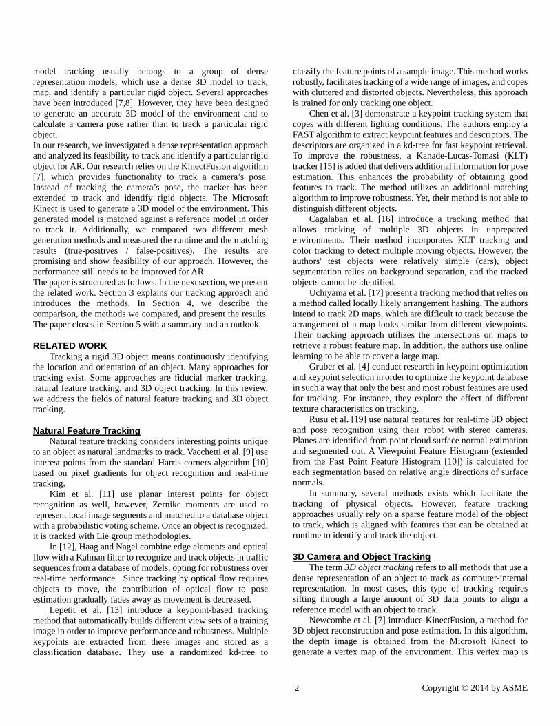
Hardware and Software Overview Figure 1 shows the hardware setup of the test system. The
tracking subject was a gear switch of a combine located on a table. This gear switch is a typical object that we need to be able to track. Its dimensions are roughly 420x150x150mm (l, w, h). In general, we have to consider that all parts for a combine assembly have a solid color, or a limited number of stickers or prints on their surface, and often a complex spatial structure.
Figure 1. The hardware setup
A Microsoft Kinect was used to obtain video images from the tracking subject. The Kinect is a camera system with two embedded camera sensors. It provides an RGB color image and a depth image with a resolution of 640x480 pixels. The Kinect was attached on a tripod and aligned towards the center of the gear switch. The output device for testing purposes was a 24" computer display. The prototype system is implemented on a PC with a 3.5 GHz Intel Xeon processor, 6GB RAM and an NVIDIA Quadro 5000 graphics processing unit (GPU).
4 Copyright © 2014 by ASME
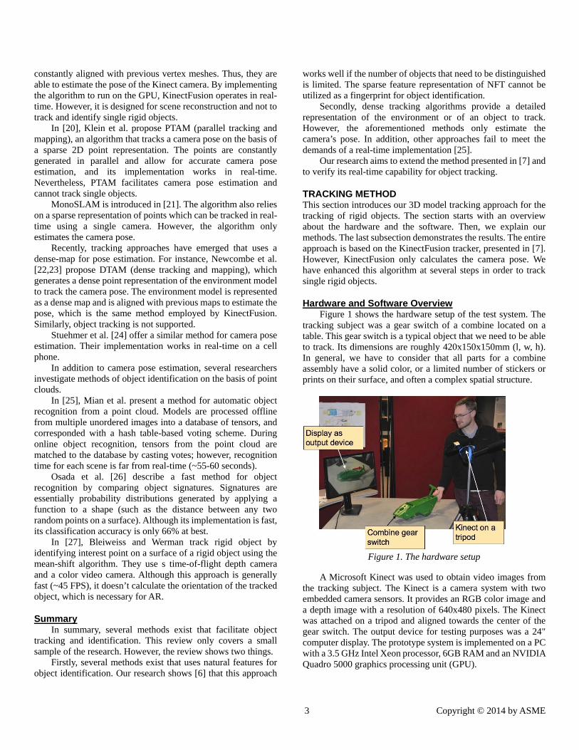
Figure 2 presents a block diagram that shows the software system. The depth video image provided by the Kinect is the input data for the tracking method. In addition, a 3D model of the object to track is loaded. The camera pose is the output data which is passed to a renderer.
The first step is a vertex map generation, as presented in [7], which incorporates vertex points and surface normal vectors. To generate the map, data from the depth image is filtered with a bilateral filter to close gaps in depth, and the surface normal vectors are calculated considering the neighbor vertices. To simplify reading, we will refer to this map as the input map. In the second step, the input map is correlated with a 3D model that represents the object to track; referred to as reference map. The reference map is generated during an initialization step and relies on the 3D model data of the object to track. We use iterative closed points (ICP) to correlate the two maps, which results in the camera pose with respect to the 3D model. The third step creates a 3D model of the environment. As described in [8] a volume truncated signed display (VTDS) function is applied to merge the input map with the existing model, created within the previous steps.
Figure 2: overview of the software setup
When the application begins, the reference model of the object to track is loaded. The model is converted into a vertex map. In general, the tracking approach works with convex and concave surfaces.
The Microsoft Kinect for Windows and OpenCV SDKs were used to develop the tracking system. The Kinect for Windows SDK is a free, proprietary software development kit that facilitates application development with the Microsoft Kinect. It provides functions to connect to the Kinect, fetch
images, generate point clouds, and match point clouds with ICP or other methods.
OpenCV is an open source computer vision library [14]. It provides functions for image processing, comparison, as well as tracking and mapping. Additionally, OpenSceneGraph (OSG), is used for rendering (www.openscenegraph.org). OSG is a scene graph programming library. It facilitates the development of computer graphics applications and provides functions for model management, rendering, and interaction. The ARToolkit, a computer vision-based tracking system, is integrated as for the initial tracking [2]. It is used to obtain the initial position and orientation of the object to track.
The following sections further explain the details to each step.
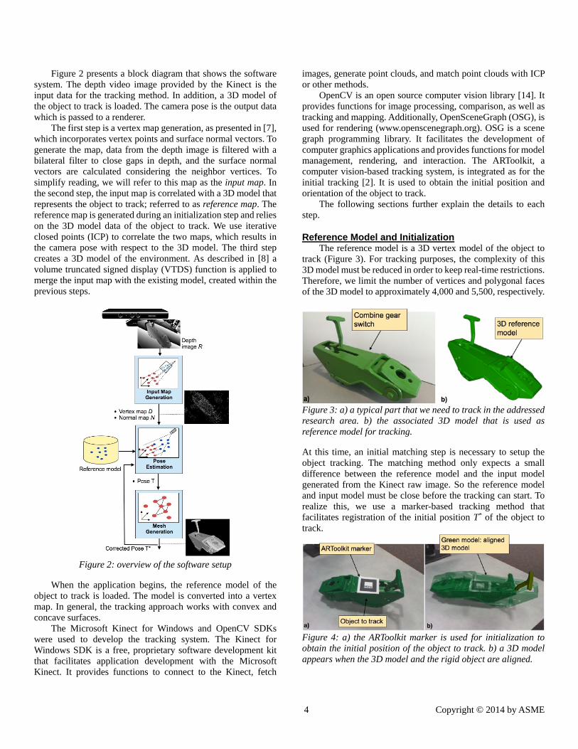
Reference Model and Initialization The reference model is a 3D vertex model of the object to
track (Figure 3). For tracking purposes, the complexity of this 3D model must be reduced in order to keep real-time restrictions. Therefore, we limit the number of vertices and polygonal faces of the 3D model to approximately 4,000 and 5,500, respectively.
Figure 3: a) a typical part that we need to track in the addressed research area. b) the associated 3D model that is used as reference model for tracking.
At this time, an initial matching step is necessary to setup the object tracking. The matching method only expects a small difference between the reference model and the input model generated from the Kinect raw image. So the reference model and input model must be close before the tracking can start. To realize this, we use a marker-based tracking method that facilitates registration of the initial position T* of the object to track.
Figure 4: a) the ARToolkit marker is used for initialization to obtain the initial position of the object to track. b) a 3D model appears when the 3D model and the rigid object are aligned.
5 Copyright © 2014 by ASME
Therefore, an ARToolkit marker is put onto the physical object to track. The ARToolkit provides a transformation matrix that describes the spatial relation between marker and the video camera, which is considered as T* and used for tracking. Once a positive match is obtained, the marker can be removed and the 3D model tracking registers the object to track.
Input Map Generation The goal of the input map generation is to generate a dense
vertex map Dt at time t from the depth image. This step follows the descriptions in [7]. Thus, we only summarize this step and refer to [7] for additional details. Consider Rt(u) as the depth image in image coordinates with the pixels u = (u, v). First, a bilateral filter [28] is applied on the depth image R in order to reduce noise:
(1)
with , Wp a normalization constant, and q, the function that performs a perspective projection. The outcome is a depth map with reduced noise.
To obtain a vertex map Vt, Dt is back-projected into the
(2)
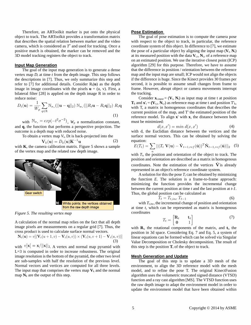
with K, the camera calibration matrix. Figure 5 shows a sample of the vertex map and the related raw depth image.
Figure 5. The resulting vertex map
A calculation of the normal map relies on the fact that all depth image pixels are measurements on a regular grid [7]. Thus, the cross product is used to calculate surface normal vectors.
(3)
with . A vertex and normal map pyramid with L=3 is computed in order to increase robustness. The original image resolution is the bottom of the pyramid, the other two level are sub-samples with half the resolution of the previous level. Normal vectors and vertices are computed for all three levels. The input map that comprises the vertex map Vk and the normal map Nk are the output of this step.
Pose Estimation The goal of pose estimation is to compute the camera pose
with respect to the object to track, in particular, the reference coordinate system of this object. In difference to [7], we estimate the pose of a particular object by aligning the input map (Vt, Nt) at its measured position with the data Vt,r, Nt,r of a reference map on an estimated position. We use the iterative closest point (ICP) algorithm [29] for this purpose. Therefore, we have to assume that the difference in position / orientation between the reference map and the input map are small; ICP would not align the objects if the difference is huge. Since the Kinect provides 30 frames per second, it is possible to assume small changes from frame to frame. However, abrupt object or camera movements interrupt the tracking.
Consider xt,input = (Vt, Nt) as input map at time t at position Tk and x't = (Vt,r, Nt,r) as reference map at time t and position T'k, with T, a matrix in homogenous coordinates that describes the current position of the map, and T' the estimated position of the reference model. To align x' with x, the distance between both must be minimized:
(4) with d, the Euclidian distance between the vertices and the surface normal vectors. This can be obtained by solving the equation:
(5)
with Tt, the position and orientation of the object to track. The position and orientation are described as a matrix in homogenous
coordinates. Note the estimation of the vertices is already represented in an object's reference coordinate system.
A solution for this the pose Tt can be obtained by minimizing the function E. The solution is a frame-to-frame approach: minimizing the function provides the incremental change between the current position at time t and the last position at t-1. Thus, the global position can be calculated as
(6) with Tt,inc, the incremental change of position and orientation
at time t, which can be represented as matrix is homogenous coordinates
(7)
with Rt, the rotational components of the matrix, and tt, the position in 3d space. Considering Eq. 7 and Eq. 5, a system of linear equations can be formed which can be solved via Singular Value Decomposition or Cholesky decomposition. The result of this step is the position Tt of the object to track.
Mesh Generation and Update The goal of this step is to update a 3D mesh of the
environment, to align the 3D reference model with the mesh model, and to refine the pose T. The original KinectFusion algorithm uses the volumetric truncated signed distance (VTSD) function and a ray cast algorithm [MS]. The VTSD function uses the raw depth image to adapt the environment model in order to update the environment model that have been obtained within
6 Copyright © 2014 by ASME
the previous steps. Originally, the ray cast algorithm is used to refine the pose T, to obtain a new vertex map, and to render an image of the surface. Therefore, a new vertex model is predicted by rendering the last environment model into a virtual camera. The created vertex model is used as reference model in the next frame to match the subsequent generated vertex map with this reference map.
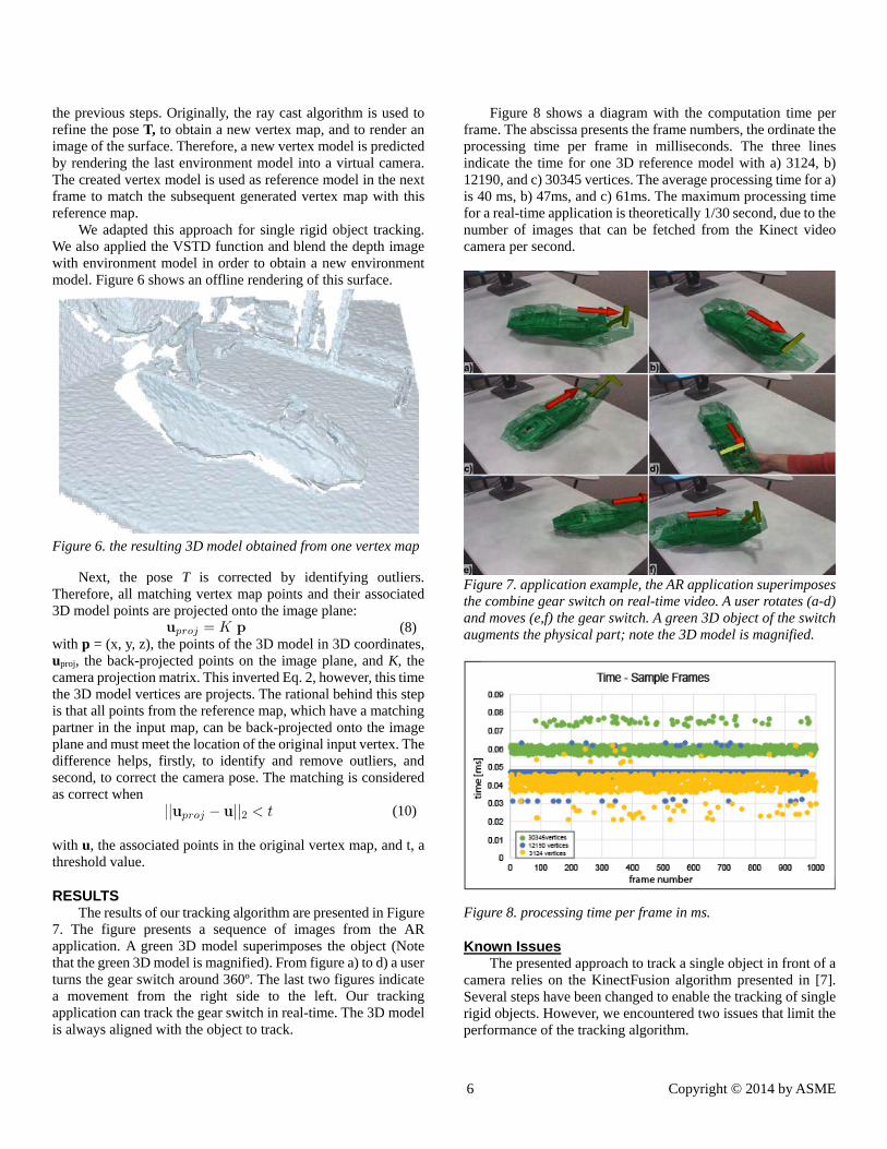
We adapted this approach for single rigid object tracking. We also applied the VSTD function and blend the depth image with environment model in order to obtain a new environment model. Figure 6 shows an offline rendering of this surface.
Figure 6. the resulting 3D model obtained from one vertex map
Next, the pose T is corrected by identifying outliers. Therefore, all matching vertex map points and their associated 3D model points are projected onto the image plane:
(8) with p = (x, y, z), the points of the 3D model in 3D coordinates, uproj, the back-projected points on the image plane, and K, the camera projection matrix. This inverted Eq. 2, however, this time the 3D model vertices are projects. The rational behind this step is that all points from the reference map, which have a matching partner in the input map, can be back-projected onto the image plane and must meet the location of the original input vertex. The difference helps, firstly, to identify and remove outliers, and second, to correct the camera pose. The matching is considered as correct when
(10) with u, the associated points in the original vertex map, and t, a threshold value.
RESULTS The results of our tracking algorithm are presented in Figure
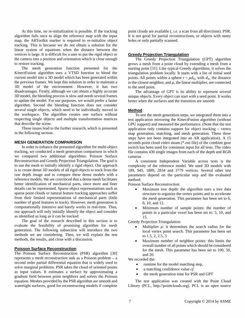
7. The figure presents a sequence of images from the AR application. A green 3D model superimposes the object (Note that the green 3D model is magnified). From figure a) to d) a user turns the gear switch around 360º. The last two figures indicate a movement from the right side to the left. Our tracking application can track the gear switch in real-time. The 3D model is always aligned with the object to track.
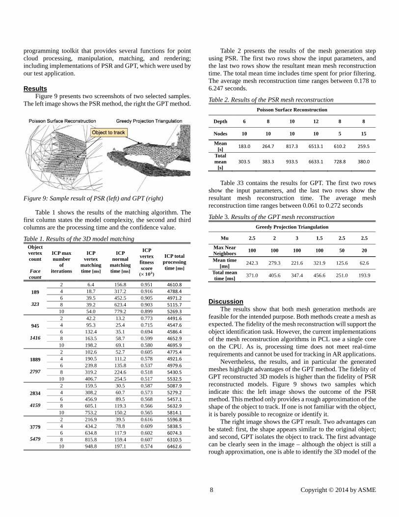
Figure 8 shows a diagram with the computation time per frame. The abscissa presents the frame numbers, the ordinate the processing time per frame in milliseconds. The three lines indicate the time for one 3D reference model with a) 3124, b) 12190, and c) 30345 vertices. The average processing time for a) is 40 ms, b) 47ms, and c) 61ms. The maximum processing time for a real-time application is theoretically 1/30 second, due to the number of images that can be fetched from the Kinect video camera per second.
Figure 7. application example, the AR application superimposes the combine gear switch on real-time video. A user rotates (a-d) and moves (e,f) the gear switch. A green 3D object of the switch augments the physical part; note the 3D model is magnified.
Figure 8. processing time per frame in ms.
Known Issues The presented approach to track a single object in front of a
camera relies on the KinectFusion algorithm presented in [7]. Several steps have been changed to enable the tracking of single rigid objects. However, we encountered two issues that limit the performance of the tracking algorithm.
7 Copyright © 2014 by ASME
At this time, no re-initialization is possible. If the tracking algorithm fails once to align the reference map with the input map, the ARToolkit marker is required to re-initialize object tracking. This is because we do not obtain a solution for the linear system of equations when the distance between the vertices is large. It is difficult for a user to put the rigid object or the camera into a position and orientation which is close enough to restore tracking.
The mesh generation function presented for the KinectFusion algorithm uses a VTSD function to blend the current model into a 3D model which has been generated within the previous frames. We kept this solution in order to maintain a 3D model of the environment. However, it has two disadvantages. Firstly, although we can obtain a highly accurate 3D model, the blending process is slow and needs several frames to update the model. For our purposes, we would prefer a faster algorithm. Second the blending function does not consider several single objects, which need to be individually moved in the workspace. The algorithm creates one surface without respecting single objects and multiple transformation matrices that describe the scene.
These issues lead to the further research, which is presented in the following section.
MESH GENERATION COMPARISON In order to enhance the presented algorithm for multi-object
tracking, we conducted a mesh generation comparison in which we compared two additional algorithms: Poisson Surface Reconstruction and Greedy Projection Triangulation. The goal is to use the mesh to initially identify a rigid object. Our approach is to create dense 3D models of all rigid objects to track from the raw depth image and to compare these dense models with a reference models. We are convinced that a dense mesh facilitates better identification of mechanical parts, since more and finer details can be represented. Sparse object representations such as sparse point clouds or natural feature tracking approaches suffer from their limited representations of mechanical parts (little number of good features to track). However, mesh generation is computationally intensive and barely works in real-time. Thus, our approach will only initially identify the object and consider as identified as long as it can be tracked.
The goal of the research described in this section is to evaluate the feasibility of promising algorithm for mesh generation. The following subsection will introduce the two methods we are considering. Then, we will explain the test methods, the results, and close with a discussion.
Poisson Surface Reconstruction The Poisson Surface Reconstruction (PSR) algorithm [30] represents a mesh reconstruction task as a Poisson problem – a second order partial differential equation that is widely used to solve marginal problems. PSR takes the cloud of oriented points as input values. It estimates a surface by approximating a gradient field between point neighbors and solves the Poisson equation. Meshes provided by the PSR algorithm are smooth and watertight surfaces, good for reconstructing models if complete
point clouds are available (, i.e. a scan from all directions). PSR. It is not good for partial reconstructions, or objects with many holes or only partially scanned.
Greedy Projection Triangulation The Greedy Projection Triangulation (GPT) algorithm
grows a mesh from a point cloud by extending a mesh from a starting point [31]. Like typical Greedy algorithms, it solves the triangulation problem locally. It starts with a list of initial seed points. All points within a sphere r = , with , the distance to the closest neighbor, and , the linear multiplier, are connected to the seed point.
The advantage of GPT is its ability to represent several unique objects. Every object can start with a seed point. It works better when the surfaces and the transition are smooth
Method To test the mesh generation steps, we integrated them into a
test application mirroring the KinectFusion algorithm (without GPU support) and measured the performance. (Note that the test application only contains support for object tracking – vertex map generation, matching, and mesh generation. These three steps have not been integrated into an AR application). A 15 seconds point cloud video steam (*.oni file) of the combine gear switch has been used for consistent input for all tests. The video file contains 430 single images from each of the depth and RGB cameras
A consistent Independent Variable across tests is the complexity of the reference model. We used 3D models with 189, 945, 1889, 2834 and 3779 vertices. Several other test parameters depend on the particular step and the evaluated method: Poisson Surface Reconstruction:
Maximum tree depth: the algorithm uses a tree data structure to organize the vertex points and to accelerate the mesh generation. This parameter has been set to 6, 8, 10, and 12.
Minimum number of sample points: the number of points in a particular voxel has been set to: 5, 10, and 15.
Greedy Projection Triangulation: Multiplier : it determines the search radius for the
local vertex point search. This parameter has been set to 1.5, 2, 2.5, 3
Maximum number of neighbor points: this limits the overall number of all points which should be considered for the mesh. This parameter has been set to 100, 50, and 20.
We recorded the: runtime for the model matching step, a matching confidence value cf. the mesh generation time for PSR and GPT
The test application was created with the Point Cloud Library (PCL, http://pointclouds.org). PCL is an open source
8 Copyright © 2014 by ASME
programming toolkit that provides several functions for point cloud processing, manipulation, matching, and rendering; including implementations of PSR and GPT, which were used by our test application.
Results Figure 9 presents two screenshots of two selected samples.
The left image shows the PSR method, the right the GPT method.
Figure 9: Sample result of PSR (left) and GPT (right)
Table 1 shows the results of the matching algorithm. The first column states the model complexity, the second and third columns are the processing time and the confidence value.
Table 1. Results of the 3D model matching Object vertex count
Face count
ICP max number
of iterations
ICP vertex
matching time [ms]
ICP normal
matching time [ms]
ICP vertex fitness score
( )
ICP total processing time [ms]
189
323
2 6.4 156.8 0.951 4610.8
4 18.7 317.2 0.916 4788.4
6 39.5 452.5 0.905 4971.2
8 39.2 623.4 0.903 5115.7
10 54.0 779.2 0.899 5269.3
945
1416
2 42.2 13.2 0.773 4491.6
4 95.3 25.4 0.715 4547.6
6 132.4 35.1 0.694 4586.4
8 163.5 58.7 0.599 4652.9
10 198.2 69.1 0.580 4695.9
1889
2797
2 102.6 52.7 0.605 4775.4
4 190.5 111.2 0.578 4921.6
6 239.8 135.8 0.537 4979.6
8 319.2 224.6 0.518 5430.5
10 406.7 254.5 0.517 5532.5
2834
4159
2 159.5 30.5 0.587 5087.9
4 308.2 60.7 0.573 5279.2
6 456.9 89.5 0.568 5457.1
8 605.1 119.3 0.566 5632.9
10 753.2 150.2 0.565 5814.1
3779
5479
2 216.9 39.5 0.616 5596.8
4 434.2 78.8 0.609 5838.5
6 634.8 117.9 0.602 6074.3
8 815.8 159.4 0.607 6310.5
10 948.8 197.1 0.574 6462.6
Table 2 presents the results of the mesh generation step using PSR. The first two rows show the input parameters, and the last two rows show the resultant mean mesh reconstruction time. The total mean time includes time spent for prior filtering. The average mesh reconstruction time ranges between 0.178 to 6.247 seconds.
Table 2. Results of the PSR mesh reconstruction
Poisson Surface Reconstruction
Depth 6 8 10 12 8 8
Nodes 10 10 10 10 5 15
Mean [s]
183.0 264.7 817.3 6513.1 610.2 259.5
Total mean
[s] 303.5 383.3 933.5 6633.1 728.8 380.0
Table 33 contains the results for GPT. The first two rows
show the input parameters, and the last two rows show the resultant mesh reconstruction time. The average mesh reconstruction time ranges between 0.061 to 0.272 seconds
Table 3. Results of the GPT mesh reconstruction
Greedy Projection Triangulation
Mu 2.5 2 3 1.5 2.5 2.5
Max Near Neighbors
100 100 100 100 50 20
Mean time [ms]
242.3 279.3 221.6 321.9 125.6 62.6
Total mean time [ms]
371.0 405.6 347.4 456.6 251.0 193.9
Discussion The results show that both mesh generation methods are
feasible for the intended purpose. Both methods create a mesh as expected. The fidelity of the mesh reconstruction will support the object identification task. However, the current implementations of the mesh reconstruction algorithms in PCL use a single core on the CPU. As is, processing time does not meet real-time requirements and cannot be used for tracking in AR applications.
Nevertheless, the results, and in particular the generated meshes highlight advantages of the GPT method. The fidelity of GPT reconstructed 3D models is higher than the fidelity of PSR reconstructed models. Figure 9 shows two samples which indicate this: the left image shows the outcome of the PSR method. This method only provides a rough approximation of the shape of the object to track. If one is not familiar with the object, it is barely possible to recognize or identify it.
The right image shows the GPT result. Two advantages can be stated: first, the shape appears similar to the original object; and second, GPT isolates the object to track. The first advantage can be clearly seen in the image – although the object is still a rough approximation, one is able to identify the 3D model of the
9 Copyright © 2014 by ASME
object to track. Changing the maximum number of points for the mesh would also increase its fidelity.
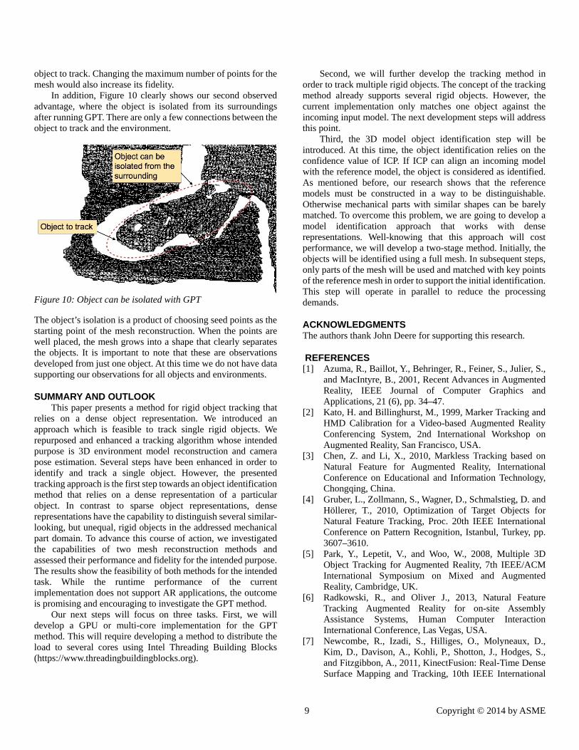
In addition, Figure 10 clearly shows our second observed advantage, where the object is isolated from its surroundings after running GPT. There are only a few connections between the object to track and the environment.
Figure 10: Object can be isolated with GPT
The object’s isolation is a product of choosing seed points as the starting point of the mesh reconstruction. When the points are well placed, the mesh grows into a shape that clearly separates the objects. It is important to note that these are observations developed from just one object. At this time we do not have data supporting our observations for all objects and environments.
SUMMARY AND OUTLOOK This paper presents a method for rigid object tracking that
relies on a dense object representation. We introduced an approach which is feasible to track single rigid objects. We repurposed and enhanced a tracking algorithm whose intended purpose is 3D environment model reconstruction and camera pose estimation. Several steps have been enhanced in order to identify and track a single object. However, the presented tracking approach is the first step towards an object identification method that relies on a dense representation of a particular object. In contrast to sparse object representations, dense representations have the capability to distinguish several similar-looking, but unequal, rigid objects in the addressed mechanical part domain. To advance this course of action, we investigated the capabilities of two mesh reconstruction methods and assessed their performance and fidelity for the intended purpose. The results show the feasibility of both methods for the intended task. While the runtime performance of the current implementation does not support AR applications, the outcome is promising and encouraging to investigate the GPT method.
Our next steps will focus on three tasks. First, we will develop a GPU or multi-core implementation for the GPT method. This will require developing a method to distribute the load to several cores using Intel Threading Building Blocks (https://www.threadingbuildingblocks.org).
Second, we will further develop the tracking method in order to track multiple rigid objects. The concept of the tracking method already supports several rigid objects. However, the current implementation only matches one object against the incoming input model. The next development steps will address this point.
Third, the 3D model object identification step will be introduced. At this time, the object identification relies on the confidence value of ICP. If ICP can align an incoming model with the reference model, the object is considered as identified. As mentioned before, our research shows that the reference models must be constructed in a way to be distinguishable. Otherwise mechanical parts with similar shapes can be barely matched. To overcome this problem, we are going to develop a model identification approach that works with dense representations. Well-knowing that this approach will cost performance, we will develop a two-stage method. Initially, the objects will be identified using a full mesh. In subsequent steps, only parts of the mesh will be used and matched with key points of the reference mesh in order to support the initial identification. This step will operate in parallel to reduce the processing demands.
ACKNOWLEDGMENTS The authors thank John Deere for supporting this research.
REFERENCES [1] Azuma, R., Baillot, Y., Behringer, R., Feiner, S., Julier, S.,
and MacIntyre, B., 2001, Recent Advances in Augmented Reality, IEEE Journal of Computer Graphics and Applications, 21 (6), pp. 34–47.
[2] Kato, H. and Billinghurst, M., 1999, Marker Tracking and HMD Calibration for a Video-based Augmented Reality Conferencing System, 2nd International Workshop on Augmented Reality, San Francisco, USA.
[3] Chen, Z. and Li, X., 2010, Markless Tracking based on Natural Feature for Augmented Reality, International Conference on Educational and Information Technology, Chongqing, China.
[4] Gruber, L., Zollmann, S., Wagner, D., Schmalstieg, D. and Höllerer, T., 2010, Optimization of Target Objects for Natural Feature Tracking, Proc. 20th IEEE International Conference on Pattern Recognition, Istanbul, Turkey, pp. 3607–3610.
[5] Park, Y., Lepetit, V., and Woo, W., 2008, Multiple 3D Object Tracking for Augmented Reality, 7th IEEE/ACM International Symposium on Mixed and Augmented Reality, Cambridge, UK.
[6] Radkowski, R., and Oliver J., 2013, Natural Feature Tracking Augmented Reality for on-site Assembly Assistance Systems, Human Computer Interaction International Conference, Las Vegas, USA.
[7] Newcombe, R., Izadi, S., Hilliges, O., Molyneaux, D., Kim, D., Davison, A., Kohli, P., Shotton, J., Hodges, S., and Fitzgibbon, A., 2011, KinectFusion: Real-Time Dense Surface Mapping and Tracking, 10th IEEE International
10 Copyright © 2014 by ASME
Symposium on Mixed and Augmented Reality, Bern, Switzerland.
[8] Hernadez, C., Vogiatzis, G, and Cipolla, R., 2007, Probabilistic Visibility for Multi-View Stereo, In Proceedings of the IEEE Conference on Computer Vision and Pattern Recognition, Minneapolis, USA.
[9] Vacchetti, L., Lepetit, V., and Fua, P., 2004, Stable Real-Time 3D Tracking Using Online and Offline Information, IEEE Transaction on Pattern Analysis and Machine Intelligence, 26 (10), pp. 1385–91.
[10] Harris C. and Stephens M., 1988, A Combined Corner and Edge Detector, Proc. of 4th Alvey Vision Conference, Manchester, UK, 15, pp. 147–151.
[11] Kim, S., Kweon, I., and Kim, I., 2003, Robust Model-Based 3D Object Recognition by Combining Feature Matching with Tracking, IEEE International Conference on Robot and Automation, 3, pp. 2123–2128.
[12] Haag M. and Nagel, H., 1999, Combination of Edge Element and Optical Flow Estimates for 3D-model-based Vehicle Tracking in Traffic Image Sequences, International Journal Computer Vision, 35, (3), pp. 295–319.
[13] Lepetit, V. and Fuab, P., 2006, Keypoint Recognition using Randomized Trees, IEEE Transactions on Pattern Analysis and Machine Intelligence, 28 (9), pp. 1465 - 1479.
[14] Laganière, R., 2011, OpenCV Computer Vision, Packt-Publishing, Birmingham.
[15] Cagalaban, G. and Kim, S., 2010, Multiple Object Tracking in Unprepared Environments Using Combined Feature for Augmented Reality Applications, Communication and Networking, Communications in Computer and Information Science, 119, pp 1-9.
[17] Uchiyama, H., Saito, H., Servières, M., Moreau, G., 2011, Camera Tracking by Online Learning of Keypoint Arrangements using LLAH in Augmented Reality Applications, Virtual Reality, 15 (2-3), pp. 109-117.
[19] Rusu, R., B., Bradski, G., Thibaux, R., and Hsu, J., 2010, Fast 3D Recognition and Pose using the Viewpoint Feature Histogram, IEEE/RSJ International Confonference Intelligence Robot System, Tapei, Taiwan , pp. 2155–2162.
[20] Klein, G. and Murray, D., 2007, Parallel Tracking and Mapping for Small AR Workspaces, Proceeedings of International Symposium on Mixed and Augmented Reality, Nara, Japan
[21] Davison, A. J., 2003, Real Time Simultaneous Localisation and Mapping with a Single Camera, Proceedings of the International Conference on Computer Vision, Nice, France, 2, pp. 1403-1410.
[22] Newcombe, R. A. and Davison, A. J., Live Dense Reconstruction with a Single Moving Camera, Proceedings of the IEEE Conference on Computer Vision and Pattern Recognition, San Francisco, USA, pp. 1498-1505
[23] Newcombe, R. A., Lovegrove, S. J., and Davison, A., J., 2011, DTAM: Dense Tracking and Mapping in Real-Time, Proceedings of the International Conference on Computer Vision, Barcellona, Spain, pp. 2320-2327.
[24] Stuehmer, J., Gumhold, S., and Cremers, D., 2010, Real-time Dense Geometry from a Handheld Camera, Proceedings of the DAGM Symposium on Pattern Recognition, Darmstadt, Germany, pp. 11-20.
[23] Mian, A. S., Bennamoun, M., and Owens, R., 2006, Three-dimensional model-based object recognition and segmentation in cluttered scenes, IEEE Transaction on Pattern Analysis and Machine Intelligence, 28 (10), pp. 1584–601.
[24] Osada, R., Funkhouser, Chazelle, B., and Dobkin, D., 2001, Matching 3D Models with Shape Distributions, International Conference on Shape Modeling and Applications, Genova, Italy, pp. 154–166.
[25] Bleiweiss A. and Werman, M., 2009, Fusing Time-of-Flight Depth and Color for Real-Time Segmentation and Tracking, Dynamic 3D Imaging, Lecture Notes in Computer Science, 5742, pp. 58-69.
[26] Tomasi, C. and Manduchi, R., 1998, Bilateral filtering for gray and color images, Proceedings of the International Conference on Computer Vision, Washington, USA, p. 839.
[27] Zhang, Z., 1994, Iterative Point Matching for Registration of Free-Form Curves and Surfaces, International Journal of Computer Vision, Springer, 13 (12), pp. 119–152.
[28] Kazhdan, M., Bolitho, M., and Hoppe, H., 2006, Poisson Surface Reconstruction, Proceedings of the 4th Eurographics symposium on Geometry Processing, Aire-la-Ville, Switzerland, pp. 61-70.
[29] Marton, Z. C., Rusu, R. B., Beetz, M., 2009, On fast surface reconstruction methods for large and noisy point clouds, IEEE International Conference on Robotics and Automation, Kobe, Japan, pp. 3218-3223.
Related Documents
