FM 4-20.112 (FM 10-512) TO 13C7-1-8 AIRDROP OF SUPPLIES AND EQUIPMENT: RIGGING TYPICAL SUPPLY LOADS MAY 2004 DISTRIBUTION RESTRICTION: Approved for public release; distribution is unlimited. HEADQUARTERS DEPARTMENT OF THE ARMY DEPARTMENT OF THE AIR FORCE

Welcome message from author
This document is posted to help you gain knowledge. Please leave a comment to let me know what you think about it! Share it to your friends and learn new things together.
Transcript

FM 4-20.112 (FM 10-512) TO 13C7-1-8
AIRDROP OF SUPPLIES AND EQUIPMENT:
RIGGING TYPICAL SUPPLY LOADS
MAY 2004
DISTRIBUTION RESTRICTION: Approved for public release; distribution is unlimited.
HEADQUARTERS
DEPARTMENT OF THE ARMY DEPARTMENT OF THE AIR FORCE

*FM 4-20.112 (FM 10-512) TO 13C7-1-8
i
FIELD MANUAL No. 4-20.112 DEPARTMENT OF THE ARMY TECHNICAL ORDER DEPARTMENT OF THE AIR FORCE No. 13C7-1-8 Washington, DC, 7 May 2004
AIRDROP OF SUPPLIES AND EQUIPMENT: RIGGING TYPICAL SUPPLY LOADS
TABLE OF CONTENTS
Paragraph Page PREFACE...……………………………………………………………………………………………………..vii CHAPTER 1 INTRODUCTION Description of Items ............................................................................1-1 1-1 Special Considerations ........................................................................1-2 1-1 Air Force Unilateral Loads..................................................................1-3 1-1 CHAPTER 2 RIGGING SUPPLY LOADS ON AN 8-FOOT, TYPE V PLATFORM FOR LOW-
VELOCITY AIRDROP SECTION I RIGGING BULK SUPPLIES Description of Load..............................................................................2-1 2-1 Preparing Platform..............................................................................2-2 2-1 Placing Honeycomb .............................................................................2-3 2-3 Positioning and Securing Load...........................................................2-4 2-4 Constructing and Installing Endboards.............................................2-5 2-6 Installing Lashings..............................................................................2-6 2-8 Installing Parachute Stowage Platform.............................................2-7 2-11 Installing Suspension Slings and Deadman's Tie .............................2-8 2-12 Preparing and Stowing Cargo Parachutes.........................................2-9 2-13 Installing the Release System ............................................................2-10 2-14 Installing the Extraction System .......................................................2-11 2-15 Placing Extraction Parachute.............................................................2-12 2-16 Installing Provisions for Emergency Restraints ...............................2-13 2-16 Marking Rigged Load..........................................................................2-14 2-16 Equipment Required ...........................................................................2-15 2-16
DISTRIBUTION RESTRICTION: Approved for public release; distribution is unlimited. ____________________________________________ *This publication supersedes FM 10-512/TO 13C7-1-8, 31 August 1979.

FM 4-20.112/TO 13C7-1-8
SECTION II RIGGING BULK SUPLIES IN A-22 CARGO BAGS
Description of Load .............................................................................2-16 2-20Preparing Platform .............................................................................2-17 2-20Placing Honeycomb ............................................................................2-18 2-20Preparing, Stowing and Rigging Load ................................................2-19 2-21Positioning Load .................................................................................2-20 2-21Installing Lashings .............................................................................2-21 2-22Installing Suspension Slings and Deadman's Tie ...............................2-22 2-26Installing Parachute Stowage Platform .............................................2-23 2-27Installing Parachutes .........................................................................2-24 2-28Installing the Release System.............................................................2-25 2-29Installing the Extraction System .......................................................2-26 2-30Placing Extraction Parachute ............................................................2-27 2-31Installing Provisions for Emergency Restraints .................................2-28 2-31Marking Rigged Load .........................................................................2-29 2-31Equipment Required ...........................................................................2-30 2-31
CHAPTER 3 RIGGING SUPPLY LOADS ON A 12-FOOT, TYPE V PLATFORM FOR LOW-VELOCITY AIRDROP
Description of Load ........................................................................... .3-1 3-1Preparing Platform ........................................................................... .3-2 3-1Placing Honeycomb ............................................................................3-3 3-3Positioning and Securing Load ......................................................... .3-4 3-4Constructing and Installing Endboards ..............................................3-5 3-6Installing Lashings .............................................................................3-6 3-8Installing Suspension Slings and Deadman's Tie ...............................3-7 3-11Installing Parachute Stowage Platform ........................................... .3-8 3-12Preparing and Stowing Cargo Parachutes ....................................... .3-9 3-13Installing the Release System........................................................... .3-10 3-14Installing the Extraction System ..................................................... .3-11 3-15Placing Extraction Parachute .......................................................... .3-12 3-16Installing Provisions for Emergency Restraint ................................ .3-13 3-16Marking Rigged Load ....................................................................... .3-14 3-16Equipment Required ......................................................................... .3-15 3-16
CHAPTER 4 RIGGING FORWARD AREA SURGICAL TEAM (FAST) EQUIPMENT ON A12-FOOT, TYPE V PLATFORM FOR LOW-VELOCITY AIRDROP
Description of Load ........................................................................... .4-1 4-1Preparing Platform ........................................................................... .4-2 4-1Positioning Lashings ..........................................................................4-3 4-3Constructing and Forming Storage Box Components ...................... .4-4 4-5Preparing Honeyconb Stacks ..............................................................3-5 4-10Positioning Honeycomb Stacks and AssemblingSides of Storage Box ............................................................................4-6 4-11
ii
Paragraph Page

FM 4-20.112/TO 13C7-1-8
Positioning Drop Items .......................................................................4-7 4-12Closing and Securing Box ...................................................................4-8 4-12Installing Lashings .............................................................................4-9 4-15Installing Suspension Slings and Deadman's Tie ...............................4-10 4-19Preparing and Stowing Cargo Parachutes .........................................4-11 4-20Installing the Release System.............................................................4-12 4-21Installing the Extraction System .......................................................4-13 4-22Placing Extraction Parachute ............................................................4-14 4-23Installing Provisions for Emergency Restraints .................................4-15 4-23Marking Rigged Load .........................................................................4-16 4-23Equipment Required ...........................................................................4-17 4-23
CHAPTER 5 RIGGING SUPPLY LOADS ON A 16-FOOT, TYPE V PLATFORM FOR LOW-VELOCITY AIRDROP
SECTION I RIGGING 105-MILLIMETER (MM) AMMUNITION
Description of Load .............................................................................5-1 5-1Preparing Platform .............................................................................5-2 5-1Building Honeycomb Stacks and Placing First Stack ........................5-3 5-3Positioning and Securing First Ammunition Stack ...........................5-4 5-4Constructing and Placing Endboards .................................................5-5 5-7Installing Lashings on First Ammunition Stack ...............................5-6 5-8Positioning and Securing Second Ammunition Stack ........................5-7 5-12Installing Lashings on Second Ammunition Stack ............................5-8 5-14Installing Load Cover, Suspension Slings and Deadman's Tie ..........5-9 5-18Installing Parachutes .........................................................................5-10 5-19Installing the Release System.............................................................5-11 5-20Installing the Extraction System .......................................................5-12 5-21Placing Extraction Parachute ............................................................5-13 5-22Installing Provisions for Emergency Restraints .................................5-14 5-22Marking Rigged Load .........................................................................5-15 5-22Equipment Required ...........................................................................5-16 5-22
SECTION II RIGGING 155-MILLIMETER (MM) AMMUNITION
Description of Load .............................................................................5-17 5-26Preparing Platform .............................................................................5-18 5-26Building Honeycomb Stacks and Placing First Stack ........................5-19 5-28Positioning and Securing First Ammunition Stack ...........................5-20 5-29Constructing Endboards .....................................................................5-21 5-31Installing Lashings on First Ammunition Stack and Firstand Second Endboards ........................................................................5-22 5-32Positioning Second Ammunition Stack and Thirdand Fourth Endboards ........................................................................5-23 5-35Lashing Second Ammunition Stack and Thirdand Fourth Endboards ........................................................................5-24 5-35Installing Suspension Slings and Deadman's Tie ...............................5-25 5-38Installing Parachutes .........................................................................5-26 5-39Installing Release System ...................................................................5-27 5-40
iii
Paragraph Page

FM 4-20.112/TO 13C7-1-8
Installing the Extraction System .......................................................5-28 5-41Placing Extraction Parachute ............................................................5-29 5-42Installing Provisions for Emergency Restraints .................................5-30 5-42Marking Rigged Load .........................................................................5-31 5-42Equipment Required ...........................................................................5-32 5-42
SECTION III RIGGING 20-MILLIMETER (MM) AMMUNITION
Description of Load .............................................................................5-33 5-46Preparing Platform .............................................................................5-34 5-46Building Honeycomb Stacks and Placing First Stack ........................5-35 5-48Positioning and Securing First Ammunition Stack ...........................5-36 5-49Constructing and Placing Endboards .................................................5-37 5-50Lashing First Ammunition Stack and Firstand Second Endboards ........................................................................5-38 5-51Positioning Endboards, Placing Second Ammunition Stack,and Pre-Positioning Lashings .............................................................5-39 5-56Lashing Second Ammunition Stack and Thirdand Fourth Endboards ........................................................................5-40 5-58Installing Load Cover, Suspension Slings and Deadman's Tie ..........5-41 5-64Installing Parachutes .........................................................................5-42 5-66Installing the Release System.............................................................5-43 5-67Installing the Extraction System .......................................................5-44 5-68Placing Extraction Parachute ............................................................5-45 5-69Installing Provisions for Emergency Restraints .................................5-46 5-69Marking Rigged Load .........................................................................5-47 5-69Equipment Required ...........................................................................5-48 5-69
SECTION IV RIGGING MASS SUPPLY BOX
Description of Load .............................................................................5-49 5-73Preparing Platform .............................................................................5-50 5-73Placing Lashings on Platform ............................................................5-51 5-75Constructing and Forming Storage Box Components ........................5-52 5-76Loading and Closing Boxes .................................................................5-53 5-80Installing Lashings .............................................................................5-54 5-81Installing Load Cover, Suspension Slings and Deadman's Tie ..........5-55 5-91Installing Parachutes .........................................................................5-56 5-92Installing the Release System.............................................................5-57 5-93Installing the Extraction System .......................................................5-58 5-94Placing Extraction Parachute ............................................................5-59 5-95Installing Provisions for Emergency Restraints .................................5-60 5-95Marking Rigged Load .........................................................................5-61 5-95Equipment Required ...........................................................................5-62 5-95
iv
Paragraph Page
FM 4-20.112/TO 13C7-1-8
CHAPTER 6 RIGGING MASS SUPPLY BOX ON A 20-FOOT, TYPE V PLATFORM FORLOW-VELOCITY AIRDROP
Description of Load .............................................................................6-1 6-1Preparing Platform .............................................................................6-2 6-1Placing Lashings on Platform ............................................................6-3 6-3Constructing and Forming Storage Box Components ........................6-4 6-4Loading and Closing the Boxes ...........................................................6-5 6-8Installing Lashings .............................................................................6-6 6-8Installing Load Cover, Suspension Slings and Deadman's Tie ..........6-7 6-17Installing Parachutes .........................................................................6-8 6-18Installing the Release System.............................................................6-9 6-19Installing the Extraction System .......................................................6-10 6-20Placing Extraction Parachute ............................................................6-11 6-21Installing Provisions for Emergency Restraints .................................6-12 6-21Marking Rigged Load .........................................................................6-13 6-21Equipment Required ...........................................................................6-14 6-21
CHAPTER 7 RIGGING PALLETIZED LOAD SYSTEM (PLS) ON A 24-FOOT, TYPE VPLATFORM FOR LOW-VELOCITY AIRDROP
SECTION I RIGGING 105-MILLIMETER (MM) AMMUNITION
Description of Load .............................................................................7-1 7-1Preparing Platform .............................................................................7-2 7-1Preparing and Positioning Honeycomb ..............................................7-3 7-3Preparing PLS Pallet .........................................................................7-4 7-7Positioning PLS Pallet on Platform ...................................................7-5 7-9Lashing PLS Pallet to Platform .........................................................7-6 7-10Placing and Lashing the Load ............................................................7-7 7-13Installing and Safetying Suspension Slings .......................................7-8 7-21Building Parachute Stowage Platform ...............................................7-9 7-23Installing Cargo Parachutes ...............................................................7-10 7-24Installing the Release System.............................................................7-11 7-25Installing the Extraction System .......................................................7-12 7-26Placing Extraction Parachute ............................................................7-13 7-27Installing Provisions for Emergency Restraints .................................7-14 7-27Marking Rigged Load .........................................................................7-15 7-27Equipment Required ...........................................................................7-16 7-27
SECTION II RIGGING A-22 CARGO BAGS
Description of Load .............................................................................7-17 7-31Preparing Platform .............................................................................7-18 7-31Preparing and Positioning Honeycomb ..............................................7-19 7-33Preparing PLS Pallet .........................................................................7-20 7-37
Paragraph Page
v

FM 4-20.112/TO 13C7-1-8
Positioning PLS Pallet on Platform ...................................................7-21 7-39Lashing PLS Pallet to Platform .........................................................7-22 7-40Placing and Lashing the Load ............................................................7-23 7-43Installing and Safetying Suspension Slings .......................................7-24 7-49Building Parachute Stowage Platform and InstallingCargo Parachutes ...............................................................................7-25 7-51Installing Release System ...................................................................7-26 7-53Installing the Extraction System .......................................................7-27 7-54Placing Extraction Parachute ............................................................7-28 7-55Installing Provisions for Emergency Restraints .................................7-29 7-55Marking Rigged Load .........................................................................7-30 7-55Equipment Required ...........................................................................7-31 7-55
CHAPTER 8 RIGGING 155-MILLIMETER (MM) AMMUNITION MODULAR ARTILLERYCHARGE SYSTEM (MACS) ON A 16-FOOT, TYPE V PLATFORM FOR LOW-VELOCITY AIRDROP
Description of Load ........................................................................... .8-1 8-1Preparing Platform ........................................................................... .8-2 8-1Building Honeycomb Stacks 1 and 2 and Positioning Stack 1 ...........8-3 8-3Positioning and Securing the First Ammunition Stack ................... .8-4 8-4Constructing Endboards .....................................................................8-5 8-8Lashing the First Ammunition Stack and Using the Firstand Second Endboards ........................................................................8-6 8-9Positioning Stack 2 and Positioning and Securing the SecondAmmunition Stack .............................................................................8-7 8-12Lashing the Second Ammunition Stack and Using the Thirdand Second Endboards ........................................................................8-8 8-16Installing Suspension Slings and Deadman's Tie ............................. .8-9 8-19Building and Positioning Parachute Stowage Platform ................... .8-10 8-20Preparing and Stowing Cargo Parachutes ....................................... .8-11 8-21Installing the Release System........................................................... .8-12 8-22Installing the Extraction System ..................................................... .8-13 8-23Placing Extraction Parachute ............................................................8-14 8-24Installing Provisions for Emergency Restraints .................................8-15 8-24Marking Rigged Load .........................................................................8-16 8-24Equipment Required ...........................................................................8-17 8-24
APPENDIX ............................................................................................................Appendix-1
GLOSSARY ............................................................................................................Glossary-1
REFERENCES ............................................................................................................References-1
Paragraph Page
vi

FM 4-20.112/TO 13C7-1-8
PREFACE
SCOPE
This manual tells and shows how to prepare and rig mass supply loads. Procedures are given for typicalloads that can be contained by the methods shown. These procedures are meant as a guide, and may beadapted to specific loads. Procedures are also given for some specific ammunition loads. This manual isdesigned for all parachute riggers.
USER INFORMATION
The proponent of this publication is HQ TRADOC. You are encouraged to report any errors or omissionsand to suggest ways to make this a better manual. Army personnel, send your comments on DA Form2028 directly to:
DirectorAerial Delivery and Field Services DepartmentUSA Quartermaster Center and School1010 Shop RoadFort Lee, Virginia 23801-1502
Air Force personnel, send your reports on AFTO Form 22 through:
HeadquartersAir Mobility Command (AMC/A3KT)402 Scott Drive, Unit 3A1Scott AFB, Illinois 62225-5302
Air Force personnel in Special Operations Command, send your reports on AFTO Form 22 through:
HQ AFSOC/DOXT100 Bartley St., Suite 2260Hurlburt Field, Florida 32544-5273
to:
vii

FM 4-20.112/TO 13C7-1-8
DirectorAerial Delivery and Field Services DepartmentUSA Quartermaster Center and School1010 Shop RoadFort Lee, Virginia 23801-1502
Also send information copy of AFTO Form 22 to:
WR-ALC/LKCB 460 Richard Ray Blvd Suite 221 Robbins AFB, GA 31098-1640
Unless this publication states otherwise, masculine nouns and pronouns do not refer exclusively to men.
viii

FM 4-20.112/TO 13C7-1-8
1-1
Chapter 1
INTRODUCTIONDESCRIPTION OF ITEMS
1-1. Bulk supplies consisting of rations, fuels, lubricants, ammunition, andvarious unit equipment can be rigged on standard airdrop platforms using theprocedures given in this manual. Items packaged in containers or units of thesame size, such as rations and ammunition are rigged using lashings andendboards. These procedures can be adapted for loads that are different from thespecific ammunition loads shown. Some items are more easily rigged in A-22containers. Items of varying and irregular size can be padded, secured, andcontained in mass supply boxes on 12, 16, and 20-foot platforms. Addition-ally, items using endboards and A-22 containers are shown rigged using thepalletized load system (PLS).
SPECIAL CONSIDERATIONS
1-2. Special considerations for this manual are given below.
a. The loads covered in this manual may include hazardous materials asdefined in AFMAN(I) 24-204/TM 38-250. If included, the hazardous materialsmust be packaged, marked, and labeled as required by AFMAN(I) 24-204/TM38-250.
b. Only ammunition listed in FM 4-20.153/MCRP 4-11.3B/TO 13C7-18-41 may be airdropped.
c. A copy of this manual must be available to the joint airdrop inspectorsduring the before- and after-loading inspection.
AIR FORCE UNILATERAL LOADS
1-3. Air Force unilateral loads are used to support wing airdrop proficiencyrequirements. The loads are designed as an alternative to actual rigged loads,using the procedures for rigging mass supplies on an 8-foot Type V platform.Ballast for the unilateral platform loads normally consists of railroad ties,lumber or ammo boxes filled with dirt or rocks, however any material may beused as long as it is sufficiently restrained. The following exceptions to FM 4-20.102/NAVSEA SS400-AB-MMO-010/TO 13C7-1-5 and this manual areauthorized for Air Force unilateral loads only:
CAUTIONThe load weights may vary from the loads shown. Be sure that each load is weighed, and theparachute requirements, CB, and tip-off curve computed.

FM 4-20.112/TO 13C7-1-8
a. Honeycomb is not required under the ballast; however, due to the lack ofhoneycomb, the life span of the Type V platform may be reduced. Units mustinspect the platform for cracks, loose rivets, delaminating panels, and generaldamage prior to each drop. All loads must be re-rigged and re-inspected after eachairdrop.
b. Honeycomb or a suitable substitute (felt covered plywood) must be usedto provide a flat and stable surface for the parachutes and releases.
1-2

FM 4-20.112/TO 13C7-1-8
2-1
Chapter 2
RIGGING SUPPLY LOADS ON AN 8-FOOT, TYPE V
PLATFORM FOR LOW-VELOCITY AIRDROPSection I
RIGGING BULK SUPPLIES
DESCRIPTION OF LOAD
2-1. Bulk supplies consisting of rations, equipment, fuel, ammunition, or otheritems of general supply are rigged on an 8-foot, type V airdrop platform withG-11 cargo parachutes. Items packaged or configured so that they can berestrained by endboards and lashings can be airdropped using these proce-dures. Modifications to the honeycomb, endboards, and lashings may benecessary to allow for items of different sizes and shapes from those shown.For extraction purposes, the rigged load must weigh at least 2,520 pounds.Refer to FM 4-20.102/NAVSEA SS400-AB-MMO-010/TO 13C7-1-5 for theweight limitations for the number of parachutes to be used.
PREPARING PLATFORM
2-2. Prepare an 8-foot, type V platform as shown in Figure 2-1.

FM 4-20.112/TO 13C7-1-8
2-2
Step:
1. Inspect, or assemble and inspect, an 8-foot, type V platform as outlined in TM 10-1670-268-20&P/TO 13C7-52-22.
2. Install a tandem link to the front of each platform side rail using holes 1, 2, and 3.
3. Install a tandem link to the rear of each platform side rail using holes 14, 15, and16.
4. Starting at the front of the right and left platform side rail, install clevises on thebushings bolted to holes 4, 5, 6, 7, 8, 9, 10, 11, 12, and 13.
5. Starting at the front of the platform, number the clevises 1 through 10 on the rightside, and 1A through 10A on the left side.
6. Label the tiedown rings according to FM 4-20.102/NAVSEA SS400-AB-MMO-010/TO 13C7-1-5.
Figure 2-1. Platform Prepared
CLEVISES 10 THROUGH 1
CLEVISES 10A THROUGH 1A
REAR FRONT
RIGHT
LEFT

FM 4-20.112/TO 13C7-1-8
2-3
PLACING HONEYCOMB
2-3. Place the honeycomb on the platform as shown in Figure 2-2.
1 Glue two full 36- by 96-inch sheets of honeycomb together. Center them 12 inches from thefront edge of the platform.
2 Make a stack as in step 1 above and place it flush against the stack placed in step 1.
Figure 2-2. Honeycomb Placed
Notes:1. When ammunition is dropped, two layers of honeycomb arerequired.2. When rigging this load for airdrop on a drop zone with groundelevation of 6,000 to 10,000 feet, add an additional layer of honeycomb.3. Adjust the dimensions of the honeycomb to fit the items beingdropped.4. Do not cover the extraction bracket with honeycomb.
2 1

FM 4-20.112/TO 13C7-1-8
2-4
POSITIONING AND SECURING LOAD
2-4. Place four 30-foot lashings on the honeycomb, place the load on thehoneycomb, and secure the lashings as shown in Figure 2-3. Adapt theprocedures shown for loads configured differently.
CAUTIONOnly ammunition listed in FM 4-20.153/MCRP 4-11.3B/TO 13C7-18-41 may beairdropped. Hazardous material must be packaged, marked, and labeled asrequired by AFMAN(I) 24-204/TM 38-250.
1 Form four 30-foot lashings according to FM 4-20.102/NAVSEA SS400-AB-MMO-010/TO 13C7-1-5. Center a lashing across the honeycomb 6 inches from each end.
2 Center two lashings on the joint in the honeycomb, 12 inches apart.
Figure 2-3. Load Positioned and Secured
1
2
1
FM 4-20.112/TO 13C7-1-8
2-5
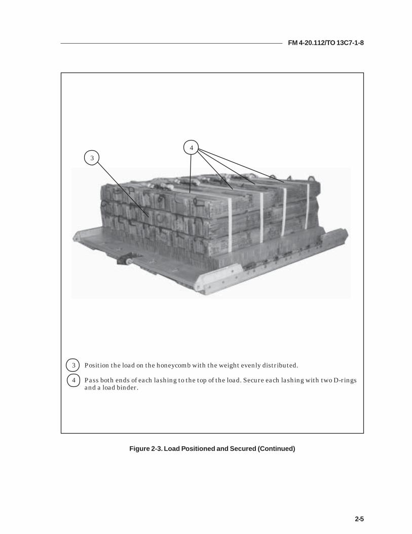
Figure 2-3. Load Positioned and Secured (Continued)
3 Position the load on the honeycomb with the weight evenly distributed.
4 Pass both ends of each lashing to the top of the load. Secure each lashing with two D-ringsand a load binder.
3
4

FM 4-20.112/TO 13C7-1-8
2-6
CONSTRUCTING AND INSTALLING ENDBOARDS
2-5. Construct the endboards and install them on the load as shown inFigure 2-4.
Notes:1. This drawing is not to scale.2. All dimensions are in inches.3. The dimensions of the endboards will vary, depending on the loadbeing rigged. The endboards must be even with the top of the load.
Figure 2-4. Endboards Constructed and Installed
1 Construct two endboards using one 3/4- by 28- by 96-inch piece of plywood for each endboard.Make cutouts as shown.
Note: Tape or pad the cutouts in the endboards to protect the lashings from sharpedges.
5
2
23
28 7
12
96
1

FM 4-20.112/TO 13C7-1-8
2-7
2 Place one endboard against the front of the load.
3 Place one endboard against the rear of the load.
4 Pass the free end of a 15-foot lashing through tie-down ring A4 and through its own D-ring.Pull the free end of the lashing over the top of the load.
5 Pass the free end of a 15-foot lashing through tie-down ring D4 and through its own D-ring.Pull the free end of the lashing over the top of the load.
6 Secure the end of the lashing positioned in step 4 to tie-down ring A1 with a D-ring and aload binder.
7 Secure the end of the lashing positioned in step 5 to tie-down ring B1 with a D-ring and aload binder.
Note: Loads longer than the one shown may be secured in this way, if the lashingsare pre-positioned under the honeycomb and endboards, and secured at both endsto the tie-down rings as shown in steps 4 and 5. Do not cover the extraction bracket.
Figure 2-4. Endboards Constructed and Installed (Continued)
A1
B1
D4
A4
27
6
3
45

FM 4-20.112/TO 13C7-1-8
2-8
INSTALLING LASHINGS
2-6. Lash the load to the platform according to FM 4-20.102/NAVSEA SS400-AB- MMO-010/TO 13C7-1-5, and as shown in Figures 2-5, 2-6, and 2-7.
4
3
1
2
14710
Figure 2-5. Lashings 1 Through 4 Installed
gnihsaLrebmuN
nwodeiTrebmuNsivelC
snoitcurtsnI
1 A1ot1 -Dnwostihguorhtdna1sivelchguorhtgnihsalassaPehteruceS.A1sivelcotdna,daolehtfopotehtrevo,gnir
.rednibdaoladnagnir-DahtiwA1sivelcotgnihsal
2 A4ot4 -Dnwostihguorhtdna4sivelchguorhtgnihsalassaPehteruceS.A4sivelcotdna,daolehtfopotehtrevo,gnir
.rednibdaoladnagnir-DahtiwA4sivelcotgnihsal
3 A7ot7 -Dnwostihguorhtdna7sivelchguorhtgnihsalassaPehteruceS.A7sivelcotdna,daolehtfopotehtrevo,gnir
.rednibdaoladnagnir-DahtiwA7sivelcotgnihsal
4 A01ot01 -Dnwostihguorhtdna01sivelchguorhtgnihsalassaPeruceS.A01sivelcotdna,daolehtfopotehtrevo,gnir
.rednibdaoladnagnir-DahtiwA01sivelcotgnihsaleht

FM 4-20.112/TO 13C7-1-8
2-9
Figure 2-6. Lashings 5 Through 7 Installed
gnihsaLrebmuN
nwodeiTrebmuNsivelC
snoitcurtsnI
5 A2dna2 stihguorhtdna2sivelchguorhtgnihsaltoof-51assaPtnorfehtnituotucrewolehthguorhtdna,gnir-Dnwo
dnaA2sivelchguorhtgnihsalrehtonassaP.draobdnenituotucrewolehthguorhtdna,gnir-Dnwostihguorht
ehtnirehtegotsgnihsalehteruceS.draobdnetnorfehtdaoladnasgnir-Dowthtiwdraobdnetnorfehtfoelddim
.rednib
6 A3dna3 stihguorhtdna3sivelchguorhtgnihsaltoof-51assaPtnorfehtnituotucreppuehthguorhtdna,gnir-DnwodnaA3sivelchguorhtgnihsalrehtonassaP.draobdnenituotucreppuehthguorhtdna,gnir-Dnwostihguorht
ehtnirehtegotsgnihsalehteruceS.draobdnetnorfehtdaoladnasgnir-Dowthtiwdraobdnetnorfehtfoelddim
.rednib
7 A5dna5 stihguorhtdna5sivelchguorhtgnihsaltoof-51assaPtnorfehtnituotucreppuehthguorhtdna,gnir-DnwodnaA5sivelchguorhtgnihsalrehtonassaP.draobdnenituotucreppuehthguorhtdna,gnir-DnwostihguorhtehtnirehtegotsgnihsalehteruceS.draobdnetnorfeht
daoladnasgnir-Dowthtiwdraobdnetnorfehtfoelddim.rednib
23
55
67
Note: Position the load binders so that they will be accessible for retightening andinspection when the load is fully rigged.

FM 4-20.112/TO 13C7-1-8
2-10
gnihsaLrebmuN
nwodeiTrebmuNsivelC
snoitcurtsnI
8 A9dna9 stihguorhtdna9sivelchguorhtgnihsaltoof-51assaPraerehtnituotucrewolehthguorhtdna,gnir-Dnwo
dnaA9sivelchguorhtgnihsalrehtonassaP.draobdnenituotucrewolehthguorhtdna,gnir-Dnwostihguorht
ehtnirehtegotsgnihsalehteruceS.draobdneraerehtdaoladnasgnir-Dowthtiwdraobdneraerehtfoelddim
.rednib
9 A8dna8 stihguorhtdna8sivelchguorhtgnihsaltoof-51assaPraerehtnituotucreppuehthguorhtdna,gnir-Dnwo
dnaA8sivelchguorhtgnihsalrehtonassaP.draobdnenituotucreppuehthguorhtdna,gnir-Dnwostihguorht
ehtnirehtegotsgnihsalehteruceS.draobdneraerehtdaoladnasgnir-Dowthtiwdraobdneraerehtfoelddim
.rednib
01 A6dna6 stihguorhtdna6sivelchguorhtgnihsaltoof-51assaPraerehtnituotucreppuehthguorhtdna,gnir-Dnwo
dnaA6sivelchguorhtgnihsalrehtonassaP.draobdnenituotucreppuehthguorhtdna,gnir-Dnwostihguorht
ehtnirehtegotsgnihsalehteruceS.draobdneraerehtdaoladnasgnir-Dowthtiwdraobdneraerehtfoelddim
.rednib
98
68
10
9
Figure 2-7. Lashings 8 Through 10 Installed

FM 4-20.112/TO 13C7-1-8
2-11
Figure 2-8. Parachute Stowage Platform Installed
INSTALLING PARACHUTE STOWAGE PLATFORM
2-7. Install the parachute stowage platform as shown in Figure 2-8.
1 Position a 60- by 36-inch piece of honeycomb along the rear endboard so that it is centeredacross the load and even with the rear endboard.
2 Tape the edges of the honeycomb.
3 Tie the honeycomb to the nearest lashings with three lengths of type III nylon cord.
3
1
2

FM 4-20.112/TO 13C7-1-8
2-12
INSTALLING SUSPENSION SLINGS AND DEADMAN’S TIE
2-8. Install the suspension slings and deadman’s tie as shown in Figure 2-9.
1 Pass one end of an 11-foot (2-loop), type XXVI nylon suspension sling through the bellportion of a large suspension clevis. Bolt the clevis to the suspension hole of the right fronttandem link.
2 Install on the left front tandem link and the right rear and left rear tandem links an 11-foot (2-loop), type XXVI nylon suspension sling as in step 1.
3 Raise the slings and install the deadman's tie according to FM 4-20.102/NAVSEA SS400-AB-MMO-010/TO 13C7-1-5.
Figure 2-9. Suspension Slings and Deadman’s Tie Installed
2
3
1

FM 4-20.112/TO 13C7-1-8
2-13
PREPARING AND STOWING CARGO PARACHUTES
2-9. Compute the parachute requirements for the load being rigged. Prepare andstow the cargo parachutes as shown in Figure 2-10.
1 Prepare, position, and stow two G-11 cargo parachutes on top of the pre-positionedhoneycomb according to FM 4-20.102/ NAVSEA SS400-AB-MMO-010/TO 13C7-1-5.
2 Install the cargo parachute restraints according to FM 4-20.102/ NAVSEA SS400-AB-MMO-010/TO 13C7-1-5 using type VIII nylon webbing to clevises 8 and 8A.
3 Install the parachute release strap according to FM 4-20.102/ NAVSEA SS400-AB-MMO-010/TO 13C7-1-5.
Figure 2-10. Cargo Parachutes Prepared and Stowed
8
2
3
1

FM 4-20.112/TO 13C7-1-8
2-14
INSTALLING THE RELEASE SYSTEM
2-10. Prepare, attach, and safety an M-1 cargo parachute release according toFM 4-20.102/NAVSEA SS400-AB-MMO-010/TO 13C7-1-5 and as shown inFigure 2-11.
Figure 2-11. M-1 Cargo Parachute Release Installed
1 Center an 18- by 20-inch piece of honeycomb between the front edge of the boxes and theparachutes. Tape the edges of the honeycomb and secure it to the load with two lengths oftype III nylon cord.
Note: Do not cover the deadman’s tie with the release platform.
2 Prepare and install the M-1 cargo parachute release on the honeycomb releaseplatform and attach the suspension slings and riser extensions.
3 Safety the bottom of the release to a convenient point on the load with a length of typeIII nylon cord according to FM 4-20.102/NAVSEA SS400-AB-MMO-010/TO 13C7-1-5.
4 Safety the top of the release assembly to clevises 7 and 7A with a length of typeIII nylon cord according to FM 4-20.102/NAVSEA SS400-AB-MMO-010/TO 13C7-1-5.
5 S-fold and tie any excess suspension slings with one turn of type I, 1/4-inch cottonwebbing.
7
4
3
2
1
5

FM 4-20.112/TO 13C7-1-8
2-15
1 Install the components of the extraction force transfer coupling (EFTC) according to FM 4-20.102/NAVSEA SS400-AB-MMO-010/TO 13C7-1-5. Use the front mounting holes for theEFTC brackets.
2 Install a 12-foot EFTC cable according to FM 4-20.102/NAVSEA SS400-AB-MMO-010/TO13C7-1-5 and safety the cable to convenient places on the platform with one turn of type I,1/4-inch cotton webbing.
3 Attach a 9-foot (2-loop) type XXVI nylon sling according to FM 4-20.102/NAVSEA SS400-AB-MMO-010/TO 13C7-1-5 to be used as a deployment line. S-fold the excess and tie it intwo places with type I, 1/4-inch cotton webbing.
Figure 2-12. Extraction System Installed
INSTALLING THE EXTRACTION SYSTEM
2-11. Install the extraction system as shown in Figure 2-12.
12
3
1 2

FM 4-20.112/TO 13C7-1-8
2-16
PLACING EXTRACTION PARACHUTE
2-12. Select the extraction parachute and extraction line needed using the extractionline requirements table in FM 4-20.102/ NAVSEA SS400-AB-MMO-010/TO 13C7-1-5.Place the extraction parachute and line on the load for installation in the aircraft.
INSTALLING PROVISIONS FOR EMERGENCY RESTRAINTS
2-13. Select and install the provisions for the emergency aft restraints according tothe emergency aft restraint requirements table in FM 4-20.102/NAVSEA SS400-AB-MMO-010/TO 13C7-1-5.
MARKING RIGGED LOAD
2-14. Mark the rigged load according to FM 4-20.102/NAVSEA SS400-AB-MMO-010/TO 13C7-1-5, and as shown in Figure 2-13. Complete Shipper'sDeclaration for Dangerous Goods. If the load varies from the one shown, the weight,height, CB, and parachute requirements must be recomputed.
EQUIPMENT REQUIRED
2-15. Use the equipment listed in Table 2-1 to rig this load.

FM 4-20.112/TO 13C7-1-8
2-17
CAUTIONMake the final rigger inspection required by AR-59-4 and FM 4-20.102/NAVSEASS400-AB-MMO-010/TO 13C7-1-5 before the load leaves the rigging site.
RIGGED LOAD DATA
Weight..................................................................................6,344 pounds
Maximum Weight...............................................................See paragraph 2-1
Height....................................................................................56 inches
Width....................................................................................108 inches
Length..................................................................................119 inches
Overhang: Front................................................................0 inches
Rear..................................................................0 inches
Center of Balance (CB)(from front edge of the platform)......................................50 inches
Extraction System (adds 18 inches to length of platform) EFTC
Figure 2-13. Bulk Supply Load Rigged on an 8-Foot, Type V Platform forLow-Velocity Airdrop
C B

FM 4-20.112/TO 13C7-1-8
2-18
Table 2-1. Equipment Required for Rigging Bulk Supply on an 8-Foot, Type V Platform forLow-Velocity Airdrop
National Stock Item Quantity Number
8040-00-273-8713 Adhesive paste, 1-gal. As required4030-00-578-8562 Clevis, medium 44030-00-090-5354 Clevis, suspension, 1-inch (large) 54020-00-240-2146 Cord, nylon, type III, 550-lb. As required1670-00-434-5783 Coupling, airdrop extraction force transfer, w/12-ft. cable 11670-00-360-0328 Cover, clevis 28135-00-664-6958 Cushioning material (Cellulose wadding) As required8305-00-958-3685 Felt, 1/2-inch thick As required1670-01-183-2678 Leaf, extraction line (line bag) ( add 2 for C-17) 2
Line extraction:1670-01-064-4452 60-foot (1-loop), type XXVI or 11670-01-062-6313 60-foot (3-loop), type XXVI (for C-130) 11670-01-107-7652 160-foot (1-loop), type XXVI (for C-5) 11670-01-107-7652 160-foot (1-loop), type XXVI (for C-17) 11670-01-064-4452 60-foot (1-loop), type XXVI (for C-17), (drogue line) 1
Link assembly, two-point:5306-00-435-8994 Bolt, 1-inch diameter, 4-inches long (add 4 for C-5) 25310-00-232-5165 Nut, 1-inch (add 4 for C-5) 21670-00-003-1953 Plate, side, 3 3/4-inch 25365-00-007-3414 Spacer, large 25351-00-010-4659 Nail, steel wire, common, 8d As required1670-00-753-3928 Pad, energy-dissipating (honeycomb)
3- by 36- by 96-inches 5 sheets1670-01-016-7841 Parachute, cargo, G-11 3
Parachute, cargo, extraction:1670-01-063-3716 22-ft. 11670-01-063-3715 15-ft. (C-17 only) 1
Platform, airdrop, type V, 8-ft:5530-00-618-8073 Plywood, 3/4-in As required1670-01-162-2372 Clevis assembly (type V) (20)1670-01-353-8424 Extraction bracket assembly (1)1670-01-162-2381 Tandem link assembly (Multipurpose link) (4)1670-01-097-8817 Release, cargo parachute, M-1 1
Sling, cargo, airdrop:1670-01-062-6304 9-ft. (2-loop), type XXVI 11670-01-063-7760 11-ft. (2-loop), type XXVI 4

FM 4-20.112/TO 13C7-1-8
2-19
Table 2-1. Equipment Required for Rigging Bulk Supply on an 8-Foot, Type V Platform forLow-Velocity Airdrop (Continued)
National Stock Item Quantity Number
5340-00-040-8219 Strap, parachute, release, multi-knife 27501-00-266-5016 Tape, adhesive, 2-inch As required7510-00-266-6710 Tape, masking As required1670-00-937-0271 Tiedown assembly, 15-ft. 261670-01-483-8259 Towplate release mechanism (H-block) (C-17 only) 1
Webbing:8305-00-268-2411 Cotton, 1/4-inch, type I As required8305-00-082-5752 Nylon, tubular, 1/2-inch As required8305-00-263-3591 Type VIII Nylon As required

FM 4-20.112/TO 13C7-1-8
2-20
Section IIRIGGING BULK SUPPLIES IN A-22 CARGO BAGS
DESCRIPTION OF LOAD
2-16. Bulk supplies consisting of rations, equipment, fuel, ammunition, orother items of general supply are rigged on an 8-foot, type V airdrop platformwith G-11 cargo parachutes. Items packaged or configured so that they canbe contained in A-22 cargo bags can be airdropped using these procedures. Forextraction purposes, the rigged load must weigh at least 2,520 pounds. Refer toFM 4-20.102/NAVSEA SS400-AB-MMO-010/TO 13C7-1-5 for the weightlimitations for the number of parachutes to be used.
PREPARING PLATFORM
2-17. Prepare an 8-foot, type V platform as described in paragraph 2-2 and asshown in Figure 2-1.
PLACING HONEYCOMB
2-18. Place the honeycomb on the platform as shown in Figure 2-14.
Notes:1. When ammunition is dropped, two layers of honeycomb arerequired.2. When rigging this load for airdrop on a drop zone with groundelevation of 6,000 to 10,000 feet, add an additional layer ofhoneycomb.
1 Glue two full 36- by 96-inch sheets of honeycomb together. Center them 5 inches from thefront edge of the platform.
2 Glue two 96- by 13-inch pieces of honeycomb together. Center them to the rear of thehoneycomb placed in step 1.
3 Make a stack as in step 1 above and place it flush against the stack placed in step 2.
Figure 2-14. Honeycomb Placed
3 2 1

FM 4-20.112/TO 13C7-1-8
2-21
PREPARING, STOWING AND RIGGING LOAD
2-19. Prepare, stow, and rig the load in four A-22 cargo bags according toFM 10-500-3/FMFM 7-47/TO 13C7-1-11, paragraphs 9-5 through 9-7. Attach thesuspension webs according to paragraph 9-9.
POSITIONING LOAD
2-20. Position the four A-22 cargo bags on the honeycomb as shown in Figure 2-15.
Figure 2-15. Load Positioned
1 Bolt a medium cargo suspension clevis to the suspension webs of each A-22 cargo bag toaid in derigging.
2 Center four A-22 cargo bags on the honeycomb.
2
1 1
2

FM 4-20.112/TO 13C7-1-8
2-22
INSTALLING LASHINGS
2-21. Use twelve 15-foot tie-down assemblies to lash the load to the platform.Install the lashings as shown in Figures 2-16 through 2-19 and according to FM4-20.102/NAVSEA SS400-AB-MMO-010/TO 13C7-1-5.
1 Pass the free end of a 15-foot lashing through tie-down ring A4 and through its ownD-ring. Pull the free end of the lashing over the top of the load, and through both ofthe suspension clevises on the right side. Secure the free end of the lashing to tie-down ring A1 with a D-ring and a load binder.
2 Pass the free end of a 15-foot lashing through tie-down ring D4 and through its own D-ring. Pull the free end of the lashing over the top of the load, and through both of thesuspension clevises on the left side. Secure the free end of the lashing to tie-down ringB1 with a D-ring and a load binder.
Figure 2-16. Lashings 1 and 2 Installed
FRONT
REAR
A1 B1
D4 A4
2 1
1 2
CAUTIONOnly ammunition listed in FM 4-20.153/MCRP 4-11.3B/TO 13C7-18-41 may beairdropped. Hazardous material must be packaged, marked, and labeled asrequired by AFMAN(I) 24-204/TM 38-250.

FM 4-20.112/TO 13C7-1-8
2-23
gnihsaLrebmuN
nwodeiTrebmuNsivelC
snoitcurtsnI
3 1otA1 -DnwostihguorhtdnaA1sivelchguorhtgnihsalassaPehteruceS.1sivelcotdna,daolehtfopotehtrevo,gnir
.rednibdaoladnagnir-Dahtiw1sivelcotgnihsal
4 4otA4 -DnwostihguorhtdnaA4sivelchguorhtgnihsalassaPehteruceS.4sivelcotdna,daolehtfopotehtrevo,gnir
.rednibdaoladnagnir-Dahtiw4sivelcotgnihsal
5 7otA7 -DnwostihguorhtdnaA7sivelchguorhtgnihsalassaPehteruceS.7sivelcotdna,daolehtfopotehtrevo,gnir
.rednibdaoladnagnir-Dahtiw7sivelcotgnihsal
6 01otA01 -DnwostihguorhtdnaA01sivelchguorhtgnihsalassaPehteruceS.01sivelcotdna,daolehtfopotehtrevo,gnir
.rednibdaoladnagnir-Dahtiw01sivelcotgnihsal
Figure 2-17. Lashings 3 Through 6 Installed
14710
6 5 4 3
FM 4-20.112/TO 13C7-1-8
2-24
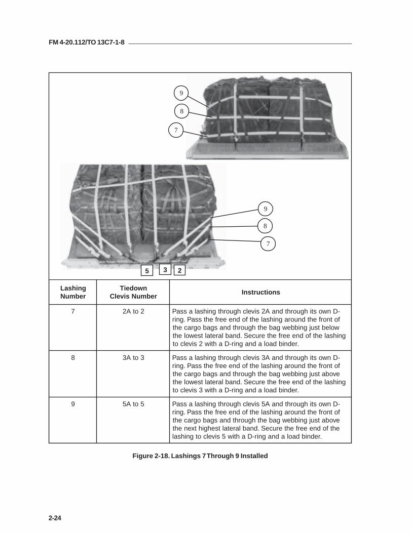
gnihsaLrebmuN
nwodeiTrebmuNsivelC
snoitcurtsnI
7 2otA2 -DnwostihguorhtdnaA2sivelchguorhtgnihsalassaPfotnorfehtdnuoragnihsalehtfodneeerfehtssaP.gnir
wolebtsujgnibbewgabehthguorhtdnasgabogracehtgnihsalehtfodneeerfehteruceS.dnablaretaltsewoleht
.rednibdaoladnagnir-Dahtiw2sivelcot
8 3otA3 -DnwostihguorhtdnaA3sivelchguorhtgnihsalassaPfotnorfehtdnuoragnihsalehtfodneeerfehtssaP.gnir
evobatsujgnibbewgabehthguorhtdnasgabogracehtgnihsalehtfodneeerfehteruceS.dnablaretaltsewoleht
.rednibdaoladnagnir-Dahtiw3sivelcot
9 5otA5 -DnwostihguorhtdnaA5sivelchguorhtgnihsalassaPfotnorfehtdnuoragnihsalehtfodneeerfehtssaP.gnir
evobatsujgnibbewgabehthguorhtdnasgabogracehtehtfodneeerfehteruceS.dnablaretaltsehgihtxeneht
.rednibdaoladnagnir-Dahtiw5sivelcotgnihsal
9
8
7
9
8
7
5 3 2
Figure 2-18. Lashings 7 Through 9 Installed

FM 4-20.112/TO 13C7-1-8
2-25
gnihsaLrebmuN
nwodeiTrebmuNsivelC
snoitcurtsnI
01 6otA6 -DnwostihguorhtdnaA6sivelchguorhtgnihsalassaPforaerehtdnuoragnihsalehtfodneeerfehtssaP.gnirevobatsujgnibbewgabehthguorhtdnasgabograceht
ehtfodneeerfehteruceS.dnablaretaltsehgiheht.rednibdaoladnagnir-Dahtiw6sivelcotgnihsal
11 8otA8 -DnwostihguorhtdnaA8sivelchguorhtgnihsalassaPforaerehtdnuoragnihsalehtfodneeerfehtssaP.gnirevobatsujgnibbewgabehthguorhtdnasgabograceht
ehtfodneeerfehteruceS.dnablaretaltsewoltxeneht.rednibdaoladnagnir-Dahtiw8sivelcotgnihsal
21 9otA9 -DnwostihguorhtdnaA9sivelchguorhtgnihsalassaPforaerehtdnuoragnihsalehtfodneeerfehtssaP.gnir
wolebtsujgnibbewgabehthguorhtdnasgabogracehtehtfodneeerfehteruceS.dnablaretaltsewoltxeneht
.rednibdaoladnagnir-Dahtiw9sivelcotgnihsal
9 8 6
12
11
10
10
11
12
Figure 2-19. Lashings 10 Through 12 Installed

FM 4-20.112/TO 13C7-1-8
2-26
INSTALLING SUSPENSION SLINGS AND DEADMAN’S TIE
2-22. Install the suspension slings and deadman’s tie as shown in Figure 2-20.
1 Pass one end of an 11-foot (2-loop), type XXVI nylon suspension sling through the bellportion of a large suspension clevis. Bolt the clevis to the suspension hole of the right fronttandem link.
2 Install on the left front tandem link and the right rear and left rear tandem links an 11-foot (2-loop), type XXVI nylon suspension sling as in step 1.
3 Raise the slings and install the deadman's tie according to FM 4-20.102/NAVSEA SS400-AB-MMO-010/TO 13C7-1-5.
Figure 2-20. Suspension Slings and Deadman’s Tie Installed
2
3
1
2

FM 4-20.112/TO 13C7-1-8
2-27
INSTALLING PARACHUTE STOWAGE PLATFORM
2-23. Install the parachute stowage platform as shown in Figure 2-21.
Figure 2-21. Parachute Stowage Platform Installed
1 Center a 60- by 36-inch piece of honeycomb along the rear edge of the cargo bags.
2 Tape the edges of the honeycomb.
3 Tie the honeycomb to the nearest lashings with two lengths of type III nylon cord.
1
2
3

FM 4-20.112/TO 13C7-1-8
2-28
INSTALLING PARACHUTES
2-24. Compute the parachute requirements for the load being rigged. Prepareand install the cargo parachutes according to FM 4-20.102/ NAVSEA SS400-AB-MMO-010/TO 13C7-1-5 and as shown in Figure 2-22.
1 Prepare, position, and stow two G-11 cargo parachutes on top of the parachute stowageplatform according to FM 4-20.102/ NAVSEA SS400-AB-MMO-010/TO 13C7-1-5.
2 Install the cargo parachute restraints according to FM 4-20.102/ NAVSEA SS400-AB-MMO-010/TO 13C7-1-5 using type VIII nylon webbing to clevises 8 and 8A.
3 Install the parachute release strap according to FM 4-20.102/ NAVSEA SS400-AB-MMO-010/TO 13C7-1-5.
8
2
1
3
Figure 2-22. Cargo Parachutes Installed

FM 4-20.112/TO 13C7-1-8
2-29
Figure 2-23. Cargo Parachutes Release System Installed
INSTALLING THE RELEASE SYSTEM
2-25. Prepare, attach, and safety an M-1 cargo parachute release according toFM 4-20.102/NAVSEA SS400-AB-MMO-010/TO 13C7-1-5 and as shown inFigure 2-23.
1 Center an 18- by 20-inch piece of honeycomb in front of the parachutes. Tape the edges ofthe honeycomb and secure it to the load with two lengths of type III nylon cord.
Note: Do not cover the deadman’s tie with the release platform.
2 Prepare and install the M-1 cargo parachute release on the honeycomb releaseplatform and attach the suspension slings and riser extensions.
3 Safety the bottom of the release to tie-down rings A1 and B1 with a length of typeIII nylon cord according to FM 4-20.102/NAVSEA SS400-AB-MMO-010/TO 13C7-1-5.
4 Safety the top of the release assembly to clevises 7 and 7A with a length of typeIII nylon cord according to FM 4-20.102/NAVSEA SS400-AB-MMO-010/TO 13C7-1-5.
5 S-fold and tie any excess suspension slings with one turn of type I, 1/4-inch cottonwebbing.
7 A1 B1
1
2
3
4
5
5

FM 4-20.112/TO 13C7-1-8
2-30
1 Install the components of the EFTC according to FM 4-20.102/NAVSEA SS400-AB-MMO-010/TO 13C7-1-5. Use the front mounting holes for the EFTC brackets.
2 Install a 12-foot EFTC cable according to FM 4-20.102/NAVSEA SS400-AB-MMO-010/TO 13C7-1-5 and safety the cable to convenient places on the platform with one turnof type I, 1/4-inch cotton webbing.
3 Attach a 9-foot (2-loop) type XXVI nylon sling according to FM 4-20.102/NAVSEA SS400-AB-MMO-010/TO 13C7-1-5 to be used as a deployment line. S-fold the excess and tie it intwo places with type I, 1/4-inch cotton webbing.
21
3
2
1
INSTALLING THE EXTRACTION SYSTEM
2-26. Install the extraction system as shown in Figure 2-24.
Figure 2-24. Extraction System Installed
FM 4-20.112/TO 13C7-1-8
2-31
PLACING EXTRACTION PARACHUTE
2-27. Select the extraction parachute and extraction line needed using the extractionline requirements table in FM 4-20.102/ NAVSEA SS400-AB-MMO-010/TO 13C7-1-5.Place the extraction parachute and line on the load for installation in the aircraft.
INSTALLING PROVISIONS FOR EMERGENCY RESTRAINTS
2-28. Select and install the provisions for the emergency aft restraints according tothe emergency aft restraint requirements table in FM 4-20.102/NAVSEA SS400-AB-MMO-010/TO 13C7-1-5.
MARKING RIGGED LOAD
2-29. Mark the rigged load according to FM 4-20.102/NAVSEA SS400-AB-MMO-010/TO 13C7-1-5, and as shown in Figure 2-25. Complete Shipper'sDeclaration for Dangerous Goods. If the load varies from the one shown, the weight,height, CB, and parachute requirements must be recomputed.
EQUIPMENT REQUIRED
2-30. Use the equipment listed in Table 2-2 to rig this load.

FM 4-20.112/TO 13C7-1-8
2-32
RIGGED LOAD DATA
Weight..................................................................................6,750 pounds
Maximum Weight...............................................................See paragraph 2-16
Height....................................................................................71 inches
Width....................................................................................108 inches
Length..................................................................................119 inches
Overhang: Front................................................................0 inches
Rear..................................................................0 inches
Center of Balance (CB)(from front edge of the platform)......................................50 inches
Extraction System (adds 18 inches to length of platform) EFTC
Figure 2-25. A-22 Cargo Bags Rigged on an 8-Foot, Type V Platform for Low-VelocityAirdrop
C B
CAUTIONMake the final rigger inspection required by AR 59-4 and FM 4-20.102/NAVSEASS400-AB-MMO-010/TO 13C7-1-5 before the load leaves the rigging site.

FM 4-20.112/TO 13C7-1-8
2-33
Table 2-2. Equipment Required for Rigging Bulk Supplies in A-22 Cargo Bags on an 8-Foot,Type V Platform for Low-Velocity Airdrop
National Stock Item Quantity Number
8040-00-273-8713 Adhesive paste, 1-gal. As required1670-00-587-3421 Bag, cargo, (A-22) 44030-00-090-5354 Clevis, suspension, 1-inch (large) 54030-00-678-8562 Clevis, 3/4-inch medium 84020-00-240-2146 Cord, nylon, type III, 550-lb. As required1670-00-434-5783 Coupling, airdrop extraction force transfer, w/12-ft. cable 11670-00-360-0328 Cover, clevis 18135-00-664-6958 Cushioning material (Cellulose wadding) As required8305-00-958-3685 Felt, 1/2-inch thick As required1670-01-183-2678 Leaf, extraction line (line bag) 2
Line extraction:1670-01-064-4452 60-foot (1-loop), type XXVI or 11670-01-062-6313 60-foot (3-loop), type XXVI (for C-130) 11670-01-107-7652 160-foot (1-loop), type XXVI (for C-5) 11670-01-107-7652 160-foot (1-loop), type XXVI (for C-17) 11670-01-064-4452 60-foot (1-loop), type XXVI (for C-17), (drogue line) 1
Link assembly, two-point:5306-00-435-8994 Bolt, 1-inch diameter, 4-inches long (add 4 for C-5) 25310-00-232-5165 Nut, 1-inch (add 4 for C-5) 21670-00-003-1953 Plate, side, 3 3/4-inch 25365-00-007-3414 Spacer, large 21670-00-753-3928 Pad, energy-dissipating (honeycomb)
3- by 36- by 96-inches 6 sheets1670-01-016-7841 Parachute, cargo, G-11 2
Parachute, cargo, extraction:1670-01-063-3716 22-ft. 11670-01-063-3715 15-ft. (C-17 only) 1
Platform, airdrop, type V, 8-ft:5530-00-618-8073 Plywood, 3/4-in As required1670-01-162-2372 Clevis assembly (type V) (20)1670-01-353-8424 Extraction bracket assembly (1)1670-01-247-2389 Link, suspension bracket, type V (2)1670-01-162-2381 Link, tandem, suspension link assembly (4)1670-01-097-8817 Release, cargo parachute, M-1 1
Sling, cargo, airdrop:1670-01-062-6304 9-ft. (2-loop), type XXVI 11670-01-063-7760 11-ft. (2-loop), type XXVI 41670-01-062-6302 20-ft. (2-loop), type XXVI 2

FM 4-20.112/TO 13C7-1-8
2-34
Table 2-2. Equipment Required for Rigging Bulk Supplies in A-22 Cargo Bags on an 8-Foot,Type V Platform for Low-Velocity Airdrop (Continued)
National Stock Item Quantity Number
5340-00-040-8219 Strap, parachute, release, multi-knife 27501-00-266-5016 Tape, adhesive, 2-inch As required7510-00-266-6710 Tape, masking As required1670-00-937-0271 Tiedown assembly, 15-ft. 121670-01-483-8259 Towplate release mechanism (H-block) (C-17 only) 1
Webbing:8305-00-268-2411 Cotton, 1/4-inch, type I As required8305-00-082-5752 Nylon, tubular, 1/2-inch As required8305-00-261-8585 Type VIII nylon As required

FM 4-20.112/TO 13C7-1-8
3-1
Chapter 3
RIGGING SUPPLY LOADS ON A 12-FOOT, TYPE V PLAT-FORM FOR LOW-VELOCITY AIRDROP
DESCRIPTION OF LOAD
3-1. Bulk supplies consisting of rations, equipment, fuel, ammunition, or otheritems of general supply are rigged on a 12-foot, type V airdrop platform withG-11 cargo parachutes. Items packaged or configured so that they can berestrained by endboards and lashings can be airdropped using theseprocedures. Modifications to the honeycomb, endboards, and lashings may benecessary to allow for items of different sizes and shapes from those shown.For extraction purposes, the rigged load must weigh at least 3,780pounds. Refer to FM 4-20.102/NAVSEA SS400-AB-MMO-010/TO 13C7-1-5 forthe weight limitations for the number of parachutes to be used.
PREPARING PLATFORM
3-2. Prepare a 12-foot, type V platform as shown in Figure 3-1.

FM 4-20.112/TO 13C7-1-8
3-2
Step:
1. Inspect, or assemble and inspect, a 12-foot, type V platform as outlined in TM 10-1670-268-20&P/TO 13C7-52-22.
2. Install a tandem link to the front of each platform side rail using holes 1, 2, and 3.
3. Install a tandem link to the rear of each platform side rail using holes 22, 23, and24.
4. Starting at the front of the right and left platform side rail, install clevises on thebushings bolted to holes 4, 5, 6, 7, 8, 9, 10, 15, 16, 17, 18, 19, 20, and 21.
5. Starting at the front of the platform, number the clevises 1 through 14 on the rightside, and 1A through 14A on the left side.
6. Label the tiedown rings according to FM 4-20.102/NAVSEA SS400-AB-MMO-010/TO 13C7-1-5.
Figure 3-1. Platform Prepared
CLEVISES 14 THROUGH 1
CLEVISES 14A THROUGH 1A
REAR FRONT
RIGHT
LEFT

FM 4-20.112/TO 13C7-1-8
3-3
PLACING HONEYCOMB
3-3. Place the honeycomb on the platform as shown in Figure 3-2.
1 Glue two full 36- by 96-inch sheets of honeycomb together. Center them 16 inches from thefront edge of the platform.
2 Make another stack as in step 1 above and place it flush against the stack placed in step 1.
3 Make another stack as in step 1 above and place it flush against the stack placed in step 2.
Figure 3-2. Honeycomb Placed
Notes:1. When ammunition is dropped, two layers of honeycomb arerequired.2. When rigging this load for airdrop on a drop zone with groundelevation of 6,000 to 10,000 feet, add an additional layer of honeycomb.3. Adjust the dimensions of the honeycomb to fit the items beingdropped.4. Do not cover the extraction bracket with honeycomb.
3 2 1

FM 4-20.112/TO 13C7-1-8
3-4
POSITIONING AND SECURING LOAD
3-4. Place six 30-foot lashings on the honeycomb, place the load on thehoneycomb, and secure the lashings as shown in Figure 3-3. Adapt theprocedures shown for loads configured differently.
1 Form six 30-foot lashings according to FM 4-20.102/NAVSEA SS400-AB-MMO-010/TO 13C7-1-5. Center a lashing across the honeycomb 6 inches from each edge.
2 Center two lashings on each joint in the honeycomb, 12 inches apart.
Figure 3-3. Load Positioned and Secured
1
2
1
CAUTIONOnly ammunition listed in FM 4-20.153/MCRP 4-11.3B/TO 13C7-18-41 may beairdropped. Hazardous material must be packaged, marked, and labeled asrequired by AFMAN(I) 24-204/TM 38-250.

FM 4-20.112/TO 13C7-1-8
3-5
Figure 3-3. Load Positioned and Secured (Continued)
3 Position the load on the honeycomb with the weight evenly distributed.
4 Pass both ends of each lashing to the top of the load. Secure each lashing with two D-ringsand a load binder.
3
4

FM 4-20.112/TO 13C7-1-8
3-6
CONSTRUCTING AND INSTALLING ENDBOARDS
3-5. Construct the endboards and install them on the load as shown inFigure 3-4.
Notes:1. This drawing is not to scale.2. All dimensions are in inches.3. The dimensions of the endboards will vary, depending on the loadbeing rigged. The endboards must be even with the top of the load.
Figure 3-4. Endboards Constructed and Installed
1 Construct two endboards using one 3/4- by 28- by 96-inch piece of plywood for each endboard.Make cutouts as shown.
Note: Tape or pad the cutouts in the endboards to protect the lashings from sharpedges.
5
2
23
28 7
12
96
1
FM 4-20.112/TO 13C7-1-8
3-7
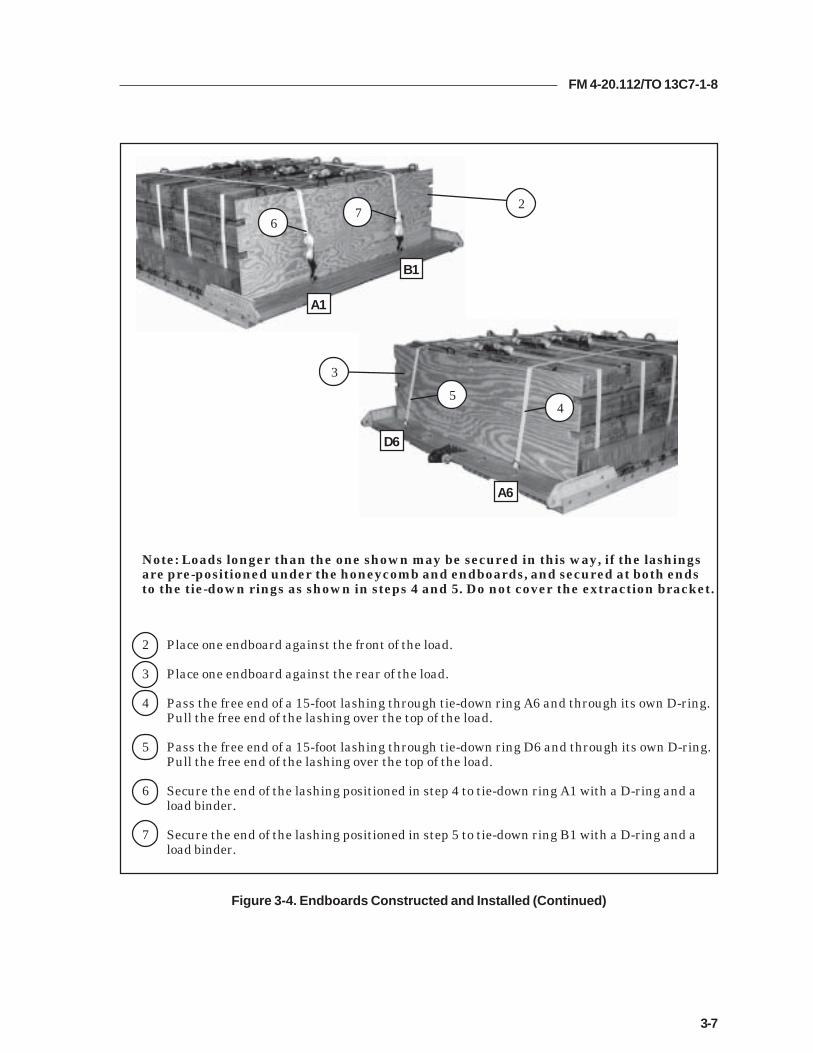
2 Place one endboard against the front of the load.
3 Place one endboard against the rear of the load.
4 Pass the free end of a 15-foot lashing through tie-down ring A6 and through its own D-ring.Pull the free end of the lashing over the top of the load.
5 Pass the free end of a 15-foot lashing through tie-down ring D6 and through its own D-ring.Pull the free end of the lashing over the top of the load.
6 Secure the end of the lashing positioned in step 4 to tie-down ring A1 with a D-ring and aload binder.
7 Secure the end of the lashing positioned in step 5 to tie-down ring B1 with a D-ring and aload binder.
Note: Loads longer than the one shown may be secured in this way, if the lashingsare pre-positioned under the honeycomb and endboards, and secured at both endsto the tie-down rings as shown in steps 4 and 5. Do not cover the extraction bracket.
Figure 3-4. Endboards Constructed and Installed (Continued)
A1
B1
D6
A6
27
6
3
45

FM 4-20.112/TO 13C7-1-8
3-8
INSTALLING LASHINGS
3-6. Lash the load to the platform according to FM 4-20.102/NAVSEA SS400-AB- MMO-010/TO 13C7-1-5, and as shown in Figures 3-5, 3-6, and 3-7.
Figure 3-5. Lashings 1 Through 6 Installed
gnihsaLrebmuN
nwodeiTrebmuNsivelC
snoitcurtsnI
1 1otA1 -DnwostihguorhtdnaA1sivelchguorhtgnihsalassaPehteruceS.1sivelcotdna,daolehtfopotehtrevo,gnir
.rednibdaoladnagnir-Dahtiw1sivelcotgnihsal
2 6otA6 -DnwostihguorhtdnaA6sivelchguorhtgnihsalassaPehteruceS.6sivelcotdna,daolehtfopotehtrevo,gnir
.rednibdaoladnagnir-Dahtiw6sivelcotgnihsal
3 7otA7 -DnwostihguorhtdnaA7sivelchguorhtgnihsalassaPehteruceS.7sivelcotdna,daolehtfopotehtrevo,gnir
.rednibdaoladnagnir-Dahtiw7sivelcotgnihsal
4 8otA8 -DnwostihguorhtdnaA8sivelchguorhtgnihsalassaPehteruceS.8sivelcotdna,daolehtfopotehtrevo,gnir
.rednibdaoladnagnir-Dahtiw8sivelcotgnihsal
5 9otA9 -DnwostihguorhtdnaA9sivelchguorhtgnihsalassaPehteruceS.9sivelcotdna,daolehtfopotehtrevo,gnir
.rednibdaoladnagnir-Dahtiw9sivelcotgnihsal
6 41otA41 -DnwostihguorhtdnaA41sivelchguorhtgnihsalassaPehteruceS.41sivelcotdna,daolehtfopotehtrevo,gnir
.rednibdaoladnagnir-Dahtiw41sivelcotgnihsal
14 9 8 7 6 1
5 4
3
2 16

FM 4-20.112/TO 13C7-1-8
3-9
Figure 3-6. Lashings 7 Through 10 Installed
2345
7
10
9
8
Note: Position the load binders so that they will be accessible for retightening andinspecting when the load is fully rigged.
gnihsaLrebmuN
nwodeiTrebmuNsivelC
snoitcurtsnI
7 A2dna2 ehtfosdneeerfehtssaP.partsnwodeittoof-03amroF,xobegarotstnorfehtnistuotucrewolehthguorhtparts
rewolehthguorhtkcabdna,A2dna2sesivelchguorhteerfehteruceS.xobegarotsehtfotnorfehtotstuotuc
.rednibdaoladnasgnir-Dowthtiwpartsehtfosdne
8 A3dna3 ehtfosdneeerfehtssaP.partsnwodeittoof-03amroF,xobegarotstnorfehtnistuotucrewolehthguorhtparts
rewolehthguorhtkcabdna,A3dna3sesivelchguorhteerfehteruceS.xobegarotsehtfotnorfehtotstuotuc
.rednibdaoladnasgnir-Dowthtiwpartsehtfosdne
9 A4dna4 ehtfosdneeerfehtssaP.partsnwodeittoof-03amroF,xobegarotstnorfehtnistuotucreppuehthguorhtparts
reppuehthguorhtkcabdna,A4dna4sesivelchguorhteerfehteruceS.xobegarotsehtfotnorfehtotstuotuc
.rednibdaoladnasgnir-Dowthtiwpartsehtfosdne
01 A5dna5 ehtfosdneeerfehtssaP.partsnwodeittoof-03amroF,xobegarotstnorfehtnistuotucreppuehthguorhtparts
reppuehthguorhtkcabdna,A5dna5sesivelchguorhteerfehteruceS.xobegarotsehtfotnorfehtotstuotuc
.rednibdaoladnasgnir-Dowthtiwpartsehtfosdne

FM 4-20.112/TO 13C7-1-8
3-10
Figure 3-7. Lashings 11 Through 14 Installed
1312
1110
1112
13
14
gnihsaLrebmuN
nwodeiTrebmuNsivelC
snoitcurtsnI
11 A01dna01 ehtfosdneeerfehtssaP.partsnwodeittoof-03amroF,xobegarotsraerehtnistuotucreppuehthguorhtparts
reppuehthguorhtkcabdna,A01dna01sesivelchguorhteerfehteruceS.xobegarotsehtforaerehtotstuotuc
.rednibdaoladnasgnir-Dowthtiwpartsehtfosdne
21 A11dna11 ehtfosdneeerfehtssaP.partsnwodeittoof-03amroF,xobegarotsraerehtnistuotucreppuehthguorhtparts
reppuehthguorhtkcabdna,A11dna11sesivelchguorhteerfehteruceS.xobegarotsehtforaerehtotstuotuc
.rednibdaoladnasgnir-Dowthtiwpartsehtfosdne
31 A21dna21 ehtfosdneeerfehtssaP.partsnwodeittoof-03amroF,xobegarotsraerehtnistuotucrewolehthguorhtparts
rewolehthguorhtkcabdna,A21dna21sesivelchguorhteerfehteruceS.xobegarotsehtforaerehtotstuotuc
.rednibdaoladnasgnir-Dowthtiwpartsehtfosdne
41 A31dna31 ehtfosdneeerfehtssaP.partsnwodeittoof-03amroF,xobegarotsraerehtnistuotucrewolehthguorhtparts
rewolehthguorhtkcabdna,A31dna31sesivelchguorhteerfehteruceS.xobegarotsehtforaerehtotstuotuc
.rednibdaoladnasgnir-Dowthtiwpartsehtfosdne

FM 4-20.112/TO 13C7-1-8
3-11
INSTALLING SUSPENSION SLINGS AND DEADMAN’S TIE
3-7. Install the suspension slings and deadman’s tie as shown in Figure 3-8.
1 Pass one end of an 11-foot (2-loop), type XXVI nylon suspension sling through the bellportion of a large suspension clevis. Bolt the clevis to the suspension hole of the rightfront tandem link.
2 Install on the left front tandem link and the right rear and left rear tandem links an 11-foot (2-loop), type XXVI nylon suspension sling as in step 1.
3 Raise the slings and install the deadman's tie according to FM 4-20.102/NAVSEA SS400-AB-MMO-010/TO 13C7-1-5.
Figure 3-8. Suspension Slings and Deadman’s Tie Installed
1
2
3

FM 4-20.112/TO 13C7-1-8
3-12
Figure 3-9. Parachute Stowage Platform Installed
INSTALLING PARACHUTE STOWAGE PLATFORM
3-8. Install the parachute stowage platform as shown in Figure 3-9.
1 Position a 60- by 36-inch piece of honeycomb along the rear endboard so that it is centeredacross the load and even with the rear endboard.
2 Tape the edges of the honeycomb.
3 Tie the honeycomb to the nearest lashings with three lengths of type III nylon cord.
3
1
2

FM 4-20.112/TO 13C7-1-8
3-13
PREPARING AND STOWING CARGO PARACHUTES
3-9. Compute the parachute requirements for the load being rigged. Prepare andstow the cargo parachutes as shown in Figure 3-10.
1 Prepare, position, and stow two G-11 cargo parachutes on top of the pre-positionedhoneycomb according to FM 4-20.102/ NAVSEA SS400-AB-MMO-010/TO 13C7-1-5.
2 Install the cargo parachute restraints according to FM 4-20.102/ NAVSEA SS400-AB-MMO-010/TO 13C7-1-5 using type VIII nylon webbing to clevises 11 and 11A.
3 Install the parachute release strap according to FM 4-20.102/ NAVSEA SS400-AB-MMO-010/TO 13C7-1-5.
Figure 3-10. Cargo Parachutes Prepared and Stowed
11
2
3
1

FM 4-20.112/TO 13C7-1-8
3-14
INSTALLING THE RELEASE SYSTEM
3-10. Prepare, attach, and safety an M-1 cargo parachute release according toFM 4-20.102/NAVSEA SS400-AB-MMO-010/TO 13C7-1-5 and as shown inFigure 3-11.
Figure 3-11. M-1 Cargo Parachute Release Installed
1 Center an 18- by 20-inch piece of honeycomb flush against the front edge of parachute.Tape the edges of the honeycomb and secure it to the load with two lengths of type IIInylon cord.
Note: Do not cover the deadman’s tie with the release platform.
2 Prepare and install the M-1 cargo parachute release on the honeycomb parachuteplatform and attach the suspension slings and riser extensions.
3 Safety the bottom of the release to tie-down rings A1 and B1 with a length of typeIII nylon cord according to FM 4-20.102/NAVSEA SS400-AB-MMO-010/TO 13C7-1-5.
4 Safety the top of the release assembly to clevises 8 and 8A with a length of typeIII nylon cord according to FM 4-20.102/NAVSEA SS400-AB-MMO-010/TO 13C7-1-5.
5 S-fold and tie any excess suspension slings with one turn of type I, 1/4-inch cottonwebbing.
8
1
2
3
4
5
5

FM 4-20.112/TO 13C7-1-8
3-15
1 Install the components of the EFTC according to FM 4-20.102/NAVSEA SS400-AB-MMO-010/TO 13C7-1-5. Use the front mounting holes for the EFTC brackets.
2 Install a 12-foot EFTC cable according to FM 4-20.102/NAVSEA SS400-AB-MMO-010/TO 13C7-1-5 and safety the cable to convenient places on the platform with one turnof type I, 1/4-inch cotton webbing.
3 Attach a 9-foot (2-loop) type XXVI nylon sling according to FM 4-20.102/NAVSEA SS400-AB-MMO-010/TO 13C7-1-5 to be used as a deployment line. S-fold the excess and tie it intwo places with type I, 1/4-inch cotton webbing.
Figure 3-12. Extraction System Installed
INSTALLING THE EXTRACTION SYSTEM
3-11. Install the extraction system as shown in Figure 3-12.
1 2
23

FM 4-20.112/TO 13C7-1-8
3-16
PLACING EXTRACTION PARACHUTE
3-12. Select the extraction parachute and extraction line needed using the extractionline requirements table in FM 4-20.102/ NAVSEA SS400-AB-MMO-010/TO 13C7-1-5.Place the extraction parachute and line on the load for installation in the aircraft.
INSTALLING PROVISIONS FOR EMERGENCY RESTRAINTS
3-13. Select and install the provisions for the emergency aft restraints according tothe emergency aft restraint requirements table in FM 4-20.102/NAVSEA SS400-AB-MMO-010/TO 13C7-1-5.
MARKING RIGGED LOAD
3-14. Mark the rigged load according to FM 4-20.102/NAVSEA SS400-AB-MMO-010/TO 13C7-1-5, and as shown in Figure 3-13. Complete Shipper'sDeclaration for Dangerous Goods. If the load varies from the one shown, the weight,height, CB, and parachute requirements must be recomputed.
EQUIPMENT REQUIRED
3-15. Use the equipment listed in Table 3-1 to rig this load.
FM 4-20.112/TO 13C7-1-8
3-17
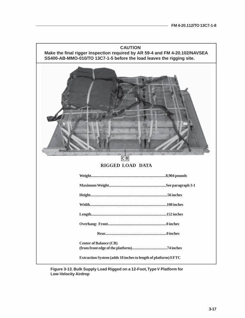
Figure 3-13. Bulk Supply Load Rigged on a 12-Foot, Type V Platform forLow-Velocity Airdrop
C B
CAUTIONMake the final rigger inspection required by AR 59-4 and FM 4-20.102/NAVSEASS400-AB-MMO-010/TO 13C7-1-5 before the load leaves the rigging site.
RIGGED LOAD DATA
Weight..................................................................................8,904 pounds
Maximum Weight...............................................................See paragraph 3-1
Height....................................................................................56 inches
Width....................................................................................108 inches
Length..................................................................................152 inches
Overhang: Front................................................................0 inches
Rear..................................................................0 inches
Center of Balance (CB)(from front edge of the platform)......................................74 inches
Extraction System (adds 18 inches to length of platform) EFTC

FM 4-20.112/TO 13C7-1-8
3-18
Table 3-1. Equipment Required for Rigging Bulk Supply on a 12-Foot, Type V Platform forLow-Velocity Airdrop
National Stock Item Quantity Number
8040-00-273-8713 Adhesive paste, 1-gal. As required4030-00-678-8562 Clevis, 3/4-inch medium 64030-00-090-5354 Clevis, suspension, 1-inch (large) 54020-00-240-2146 Cord, nylon, type III, 550-lb. As required1670-00-434-5783 Coupling, airdrop extraction force transfer, w/12-ft. cable 11670-00-360-0328 Cover, clevis 28135-00-664-6958 Cushioning material (Cellulose wadding) As required8305-00-958-3685 Felt, 1/2-inch thick As required1670-01-183-2678 Leaf, extraction line (line bag) ( add 2 for C-17) 2
Line extraction:1670-01-064-4452 60-foot (1-loop), type XXVI or 11670-01-062-6313 60-foot (3-loop), type XXVI (for C-130) 11670-01-062-6313 160-foot (3-loop), type XXVI (for C-5) 11670-01-107-7651 140-foot (3-loop), type XXVI (for C-17) 11670-01-064-4452 60-foot (1-loop), type XXVI (for C-17), (drogue line) 1
Link assembly, two-point:5306-00-435-8994 Bolt, 1-inch diameter, 4-inches long (add 4 for C-5) 25310-00-232-5165 Nut, 1-inch (add 4 for C-5) 21670-00-003-1953 Plate, side, 3 3/4-inch 25365-00-007-3414 Spacer, large (add 4 for C-5) 21670-00-753-3928 Pad, energy-dissipating (honeycomb)
3- by 36- by 96-inches 7 sheets1670-01-016-7841 Parachute, cargo, G-11 2
Parachute, cargo, extraction:1670-01-063-3716 22-ft. 11670-01-063-3715 15-ft. (C-17 only) 1
Platform, airdrop, type V, 12-ft:5530-00-618-8073 Plywood, 3/4-in As required1670-01-162-2372 Clevis assembly (type V) (36)1670-01-353-8424 Extraction bracket assembly (1)1670-01-162-2381 Tandem link assembly (Multipurpose link) (4)1670-01-097-8817 Release, cargo parachute, M-1 1
Sling, cargo, airdrop:1670-01-062-6303 9-ft. (2-loop), type XXVI 11670-01-063-7760 11-ft. (2-loop), type XXVI 41670-01-062-6302 20-ft. (2-loop), type XXVI 2

FM 4-20.112/TO 13C7-1-8
3-19
Table 3-1. Equipment Required for Rigging Bulk Supply on a 12-Foot, Type V Platform forLow-Velocity Airdrop (Continued)
National Stock Item Quantity Number
5340-00-040-8219 Strap, parachute, release, multi-knife 27501-00-266-5016 Tape, adhesive, 2-inch As required7510-00-266-6710 Tape, masking As required1670-00-937-0271 Tiedown assembly, 15-ft. 361670-01-483-8259 Towplate release mechanism (H-block) (C-17 only) 1
Webbing:8305-00-268-2411 Cotton, 1/4-inch, type I As required8305-00-082-5752 Nylon, tubular, 1/2-inch As required8305-00-261-8585 Type VIII nylon As required

FM 4-20.112/TO 13C7-1-8
4-1
Chapter 4
RIGGING FORWARD AREA SURGICAL TEAM (FAST)EQUIPMENT ON A 12-FOOT, TYPE V PLATFORM FOR
LOW-VELOCITY AIRDROP
DESCRIPTION OF LOAD
4-1. The FAST equipment is rigged as a bulk supply load on a 12-foot type Vairdrop platform with G-11 cargo parachutes. These procedures may be used torig other bulk supply loads consisting of rations, equipment, fuel, lubricants,ammunition or other items of general supply. As load weights can vary widely,the parachute requirements must be computed for each load. For extractionpurposes, the rigged load must weigh at least 3,780 pounds. Refer to FM 4-20.102/NAVSEA SS400-AB-MMO-010/TO 13C7-1-5 for the weight limitationsfor the number of parachutes to be used.
PREPARING PLATFORM
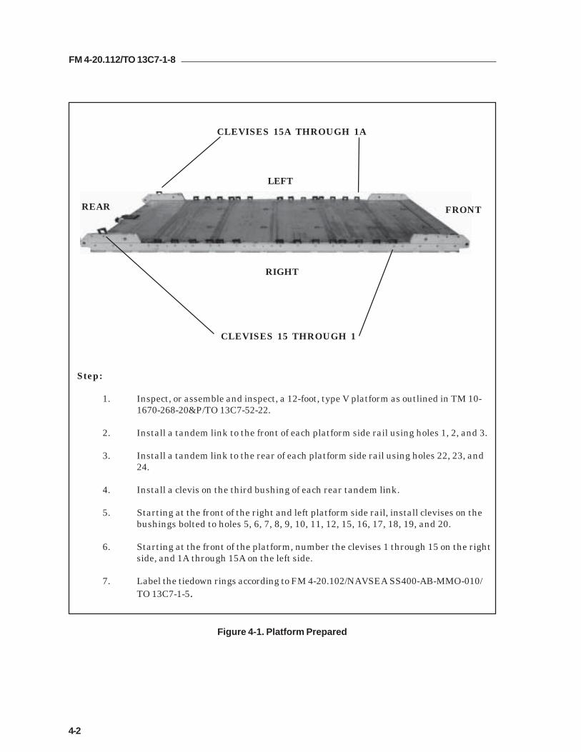
4-2. Prepare a 12-foot, type V platform as shown in Figure 4-1.
FM 4-20.112/TO 13C7-1-8
4-2
Step:
1. Inspect, or assemble and inspect, a 12-foot, type V platform as outlined in TM 10-1670-268-20&P/TO 13C7-52-22.
2. Install a tandem link to the front of each platform side rail using holes 1, 2, and 3.
3. Install a tandem link to the rear of each platform side rail using holes 22, 23, and24.
4. Install a clevis on the third bushing of each rear tandem link.
5. Starting at the front of the right and left platform side rail, install clevises on thebushings bolted to holes 5, 6, 7, 8, 9, 10, 11, 12, 15, 16, 17, 18, 19, and 20.
6. Starting at the front of the platform, number the clevises 1 through 15 on the rightside, and 1A through 15A on the left side.
7. Label the tiedown rings according to FM 4-20.102/NAVSEA SS400-AB-MMO-010/TO 13C7-1-5.
Figure 4-1. Platform Prepared
CLEVISES 15 THROUGH 1
CLEVISES 15A THROUGH 1A
REAR FRONT
RIGHT
LEFT

FM 4-20.112/TO 13C7-1-8
4-3
POSITIONING LASHINGS
4-3. Use twelve 15-foot tiedown lashings, and position the lashings on theplatform as shown in Figure 4-2.
1 Pass the free end of a 15-foot tiedown lashing through tiedown ring A2 and through its ownD-ring. Pull the free end of the strap toward the front of the platform.
2 Pass the free end of a 15-foot tiedown lashing through tiedown ring B2 and through its ownD-ring. Pull the free end of the strap toward the front of the platform.
3 Pass the free end of a 15-foot tiedown lashing through tiedown ring A2 and through its ownD-ring. Pull the free end of the strap toward the right side of the platform.
4 Pass the free end of a 15-foot tiedown lashing through tiedown ring B2 and through its ownD-ring. Pull the free end of the strap toward the left side of the platform.
5 Pass the free end of a 15-foot tiedown lashing through tiedown ring A3 and through its ownD-ring. Pull the free end of the strap toward the right side of the platform.
6 Pass the free end of a 15-foot tiedown lashing through tiedown ring B3 and through its ownD-ring. Pull the free end of the strap toward the left side of the platform.
Figure 4-2. Lashings Positioned
FRONTREAR
RIGHT
LEFT
6 42
5 3 1

FM 4-20.112/TO 13C7-1-8
4-4
Figure 4-2. Lashings Positioned (Continued)
7 Pass the free end of a 15-foot tiedown lashing through tiedown ring A4 and through its ownD-ring. Pull the free end of the strap toward the right side of the platform.
8 Pass the free end of a 15-foot tiedown lashing through tiedown ring B4 and through its ownD-ring. Pull the free end of the strap toward the left side of the platform.
9 Pass the free end of a 15-foot tiedown lashing through tiedown ring A5 and through its ownD-ring. Pull the free end of the strap toward the right side of the platform.
10 Pass the free end of a 15-foot tiedown lashing through tiedown ring B5 and through its ownD-ring. Pull the free end of the strap toward the left side of the platform.
11 Pass the free end of a 15-foot tiedown lashing through tiedown ring A5 and through its ownD-ring. Pull the free end of the strap toward the rear of the platform.
12 Pass the free end of a 15-foot tiedown lashing through tiedown ring B5 and through its ownD-ring. Pull the free end of the strap toward the rear of the platform.
FRONTREAR
81012
7911

FM 4-20.112/TO 13C7-1-8
4-5
Figure 4-3. Front and Rear Components of Storage Box Constructed
CONSTRUCTING AND FORMING STORAGE BOX COMPONENTS
4-4. Construct the individual components of a storage box as shown in Figures4-3 through 4-5. Assemble the individual components of the front and rear of thebox and the sides of the box as shown in Figure 4-6 for later assembly on theplatform.
Notes:1. This drawing is not to scale.2. All dimensions are in inches.3. Circled numbers refer to item numbers.
kcatSrebmuN seceiP
htdiW)sehcnI(
htgneL)sehcnI( lairetaM
1 2 8 69 doowylphcni-4/32 2 84 69 doowylphcni-4/33 6 65 rebmulhcni-4yb-2
96
8
2 x 4
5648
96
3
1
2

FM 4-20.112/TO 13C7-1-8
4-6
Notes:1. This drawing is not to scale.2. All dimensions are in inches.3. Circled numbers refer to item numbers.
kcatSrebmuN seceiP
htdiW)sehcnI(
htgneL)sehcnI( lairetaM
4 2 8 69 doowylphcni-4/35 2 8 2/154 doowylphcni-4/36 8 65 rebmulhcni-4yb-2
2 x 4
56
45 1/2
8
96
84
5
6
Figure 4-4. Side Components of Storage Box Constructed

FM 4-20.112/TO 13C7-1-8
4-7
Figure 4-4. Side Components of Storage Box Constructed (Continued)
Notes:1. This drawing is not to scale.2. All dimensions are in inches.3. Circled numbers refer to item numbers.
48
96
7
48
45 1/2
8
kcatSrebmuN seceiP
htdiW)sehcnI(
htgneL)sehcnI( lairetaM
7 2 84 69 doowylphcni-4/38 2 84 2/154 doowylphcni-4/3

FM 4-20.112/TO 13C7-1-8
4-8
Figure 4-5. Top Components of Storage Box Constructed
Notes:1. This drawing is not to scale.2. All dimensions are in inches.3. Circled numbers refer to item numbers.
47
96
9
kcatSrebmuN seceiP
htdiW)sehcnI(
htgneL)sehcnI( lairetaM
9 3 74 69 doowylphcni-4/3

FM 4-20.112/TO 13C7-1-8
4-9
Notes:1. This drawing is not to scale.2. All dimensions are in inches.3. Make three evenly spaced 2-inch cutouts on each 48-inch side of theplywood used for the front and rear components before assemblingthe box.
FRONT AND REAR OF STORAGE BOX
SIDES OF STORAGE BOX Step:
1. Nail the components of the storage box together with sixteen-penny nails to form thesides.
2. Bend the ends of the nails to hold the components in place securely.
Figure 4-6. Front, Rear, and Sides of Storage Box Constructed
5
8 7
4
6 6 66
333
1
2

FM 4-20.112/TO 13C7-1-8
4-10
Figure 4-7. Honeycomb Stacks Prepared
PREPARING HONEYCOMB STACKS
4-5. Prepare the honeycomb stacks as shown in Figure 4-7.
Notes:1. This drawing is not to scale.2. All dimensions are in inches.
kcatSrebmuN seceiP
htdiW)sehcnI(
htgneL)sehcnI( lairetaM snoitcurtsnI
1 2 69 03 bmocyenoH .rehtoehtfopotnoeceipenoecalP
2 2 69 63 bmocyenoH .1kcatssaemaS
3 2 69 63 bmocyenoH .1kcatssaemaS
4 2 69 63 bmocyenoH .1kcatssaemaS
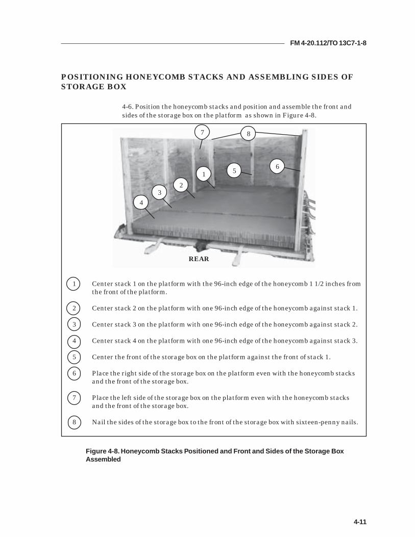
FM 4-20.112/TO 13C7-1-8
4-11
POSITIONING HONEYCOMB STACKS AND ASSEMBLING SIDES OFSTORAGE BOX
4-6. Position the honeycomb stacks and position and assemble the front andsides of the storage box on the platform as shown in Figure 4-8.
1 Center stack 1 on the platform with the 96-inch edge of the honeycomb 1 1/2 inches fromthe front of the platform.
2 Center stack 2 on the platform with one 96-inch edge of the honeycomb against stack 1.
3 Center stack 3 on the platform with one 96-inch edge of the honeycomb against stack 2.
4 Center stack 4 on the platform with one 96-inch edge of the honeycomb against stack 3.
5 Center the front of the storage box on the platform against the front of stack 1.
6 Place the right side of the storage box on the platform even with the honeycomb stacksand the front of the storage box.
7 Place the left side of the storage box on the platform even with the honeycomb stacksand the front of the storage box.
8 Nail the sides of the storage box to the front of the storage box with sixteen-penny nails.
Figure 4-8. Honeycomb Stacks Positioned and Front and Sides of the Storage BoxAssembled
43
2
1 5
7 8
6
REAR

FM 4-20.112/TO 13C7-1-8
4-12
Figure 4-9. Box Closed and Secured
POSITIONING DROP ITEMS
4-7. Position the drop items in the storage box on the honeycomb stacks.Distribute the weight of the drop items evenly on the honeycomb stacks. Padthe drop items as necessary, with honeycomb and cellulose wadding. Fill inempty areas with honeycomb to prevent shifting or movement.
CLOSING AND SECURING BOX
4-8. Close and secure the box as shown in Figure 4-9.
1 Center the rear of the storage box on the platform against the rear of stack 4. Nail the sidesof the box to the rear of the box with sixteen-penny nails.
2 Place three 3/4- by 47- by 96-inch pieces of plywood side by side on top of the box. Nail each47- by 96-inch piece of plywood to the sides of the box.
FRONTREAR
2
1
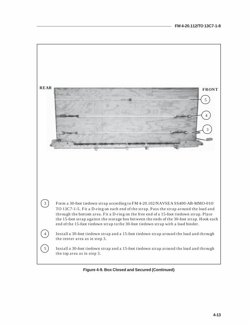
FM 4-20.112/TO 13C7-1-8
4-13
3 Form a 30-foot tiedown strap according to FM 4-20.102/NAVSEA SS400-AB-MMO-010/TO 13C7-1-5. Fit a D-ring on each end of the strap. Pass the strap around the load andthrough the bottom area. Fit a D-ring on the free end of a 15-foot tiedown strap. Placethe 15-foot strap against the storage box between the ends of the 30-foot strap. Hook eachend of the 15-foot tiedown strap to the 30-foot tiedown strap with a load binder.
4 Install a 30-foot tiedown strap and a 15-foot tiedown strap around the load and throughthe center area as in step 3.
5 Install a 30-foot tiedown strap and a 15-foot tiedown strap around the load and throughthe top area as in step 3.
Figure 4-9. Box Closed and Secured (Continued)
FRONTREAR
5
4
3

FM 4-20.112/TO 13C7-1-8
4-14
Figure 4-9. Box Closed and Secured (Continued)
6 Pass the ends of the straps attached to tiedown rings A2 and B2 to the top of the load.Hook the ends of the straps together with two D-rings and a load binder.
7 Pass the ends of the straps attached to tiedown rings A3 and B3 to the top of the load.Hook the ends of the straps together with two D-rings and a load binder.
8 Pass the ends of the straps attached to tiedown rings A4 and B4 to the top of the load.Hook the ends of the straps together with two D-rings and a load binder.
9 Pass the ends of the straps attached to tiedown rings A5 and B5 to the top of the load.Hook the ends of the straps together with two D-rings and a load binder.
10 Pass the ends of the straps attached to tiedown rings A2 and A5 to the top of the load.Hook the ends of the straps together with two D-rings and a load binder.
11 Pass the ends of the straps attached to tiedown rings B2 and B5 to the top of the load.Hook the ends of the straps together with two D-rings and a load binder.
REAR FRONT67
10
89
11

FM 4-20.112/TO 13C7-1-8
4-15
1 Form a 30-foot tiedown strap. Pass the free ends of the strap through clevises 1 and 1A.Bring the free ends to the top of the box and secure with two D-rings and a load binder.
2 Form a 30-foot tiedown strap. Pass the free ends of the strap through clevises 6 and 6A.Bring the free ends to the top of the box and secure with two D-rings and a load binder.
3 Form a 30-foot tiedown strap. Pass the free ends of the strap through clevises 9 and 9A.Bring the free ends to the top of the box and secure with two D-rings and a load binder.
4 Form a 30-foot tiedown strap. Pass the free ends of the strap through clevises 14 and 14A.Bring the free ends to the top of the box and secure with two D-rings and a load binder.
Figure 4-10. Lashings Installed
INSTALLING LASHINGS
4-9. Install the lashings as shown in Figure 4-10.
16914
1234
FRONTREAR
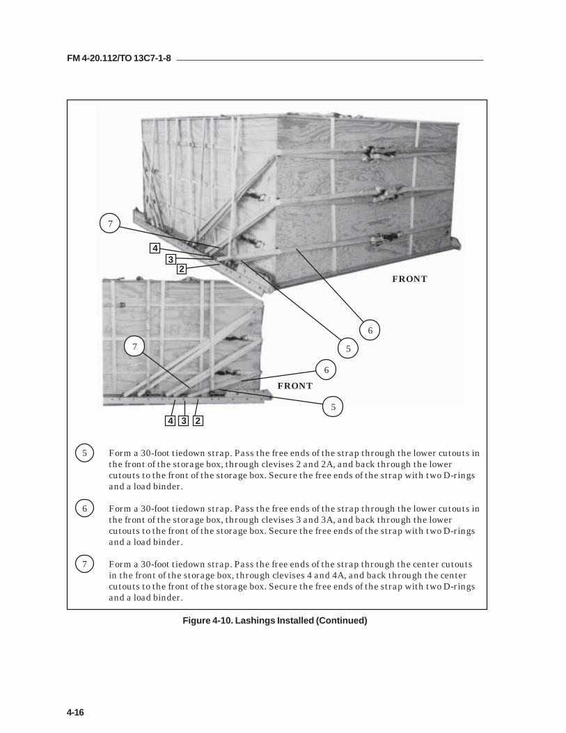
FM 4-20.112/TO 13C7-1-8
4-16
Figure 4-10. Lashings Installed (Continued)
5 Form a 30-foot tiedown strap. Pass the free ends of the strap through the lower cutouts inthe front of the storage box, through clevises 2 and 2A, and back through the lowercutouts to the front of the storage box. Secure the free ends of the strap with two D-ringsand a load binder.
6 Form a 30-foot tiedown strap. Pass the free ends of the strap through the lower cutouts inthe front of the storage box, through clevises 3 and 3A, and back through the lowercutouts to the front of the storage box. Secure the free ends of the strap with two D-ringsand a load binder.
7 Form a 30-foot tiedown strap. Pass the free ends of the strap through the center cutoutsin the front of the storage box, through clevises 4 and 4A, and back through the centercutouts to the front of the storage box. Secure the free ends of the strap with two D-ringsand a load binder.
2
43
234
FRONT
FRONT
6
5
7
6
5
7

FM 4-20.112/TO 13C7-1-8
4-17
Figure 4-10. Lashings Installed (Continued)
8 Form a 30-foot tiedown strap. Pass the free ends of the strap through the center cutoutsin the front of the storage box, through clevises 5 and 5A, and back through the centercutouts to the front of the storage box. Secure the free ends of the strap with two D-rings and a load binder.
9 Form a 30-foot tiedown strap. Pass the free ends of the strap through the top cutouts inthe front of the storage box, through clevises 7 and 7A, and back through the topcutouts to the front of the storage box. Secure the free ends of the strap with two D-ringsand a load binder.
10 Form a 30-foot tiedown strap. Pass the free ends of the strap through the top cutouts inthe front of the storage box, through clevises 8 and 8A, and back through the topcutouts to the front of the storage box. Secure the free ends of the strap with two D-ringsand a load binder.
FRONT
FRONTREAR
578
578
10
8
9
10
9
8

FM 4-20.112/TO 13C7-1-8
4-18
Figure 4-10. Lashings Installed (Continued)
11 Form a 30-foot tiedown strap. Pass the free ends of the strap through the top cutoutsin the rear of the storage box, through clevises 11 and 11A, and back through the topcutouts to the front of the storage box. Secure the free ends of the strap with two D-rings and a load binder.
12 Form a 30-foot tiedown strap. Pass the free ends of the strap through the center cutoutsin the rear of the storage box, through clevises 12 and 12A, and back through the centercutouts to the rear of the storage box. Secure the free ends of the strap with two D-ringsand a load binder.
13 Form a 30-foot tiedown strap. Pass the free ends of the strap through the lower cutouts inthe rear of the storage box, through clevises 13 and 13A, and back through the lowercutouts to the rear of the storage box. Secure the free ends of the strap with two D-ringsand a load binder.
REAR 1311
12
1112
13

FM 4-20.112/TO 13C7-1-8
4-19
INSTALLING SUSPENSION SLINGS AND DEADMAN’S TIE
4-10. Install the suspension slings and deadman’s tie as shown in Figure 4-11.
Figure 4-11. Suspension Slings and Deadman’s Tie Installed
1 Pass one end of a 16-foot (2-loop), type XXVI nylon suspension sling through the bellportion of a large suspension clevis. Bolt the clevis to the suspension hole of the rightfront tandem link.
2 Install on the left tandem link and the right rear and left rear tandem links a 16-foot(2-loop), type XXVI nylon suspension sling as in step 1.
3 Pad each suspension sling with a 9- by 24-inch piece of felt from a point 44 inches abovethe suspension clevis. Tape the felt 2 inches above and below the padding.
4 Raise the slings and install the deadman's tie according to FM 4-20.102/NAVSEA SS400-AB-MMO-010/TO 13C7-1-5.
14
3
2

FM 4-20.112/TO 13C7-1-8
4-20
PREPARING AND STOWING CARGO PARACHUTES
4-11. Compute the parachute requirements for the load being rigged. Prepareand stow the cargo parachutes as shown in Figure 4-12.
1 Place a 96- by 36-inch piece of honeycomb at the rear of the load. Tie the honeycomb inplace with type III nylon cord. Tape the honeycomb where the cord passes.
2 Prepare, position, and stow three G-11 cargo parachutes on top of the pre-positionedhoneycomb according to FM 4-20.102/ NAVSEA SS400-AB-MMO-010/TO 13C7-1-5.
3 Install the cargo parachute restraints according to FM 4-20.102/ NAVSEA SS400-AB-MMO-010/TO 13C7-1-5 using type VIII nylon webbing to clevises 15 and 15A for the rear.
4 Install the cargo parachute restraints according to FM 4-20.102/ NAVSEA SS400-AB-MMO-010/TO 13C7-1-5 using type VIII nylon webbing to clevises 10 and 10A for the front.
5 Install the parachute release strap according to FM 4-20.102/ NAVSEA SS400-AB-MMO-010/TO 13C7-1-5. (Not shown)
Figure 4-12. Cargo Parachutes Prepared and Stowed
1
2
4
3 10
15

FM 4-20.112/TO 13C7-1-8
4-21
INSTALLING THE RELEASE SYSTEM
4-12. Prepare, attach, and safety an M-1 cargo parachute release according toFM 4-20.102/NAVSEA SS400-AB-MMO-010/TO 13C7-1-5 and as shown inFigure 4-13.
Figure 4-13. Release System Installed
1 Center a 12- by 24-inch piece of honeycomb 12 inches in front of the parachutes. Tapethe edges of the honeycomb and secure it to the load with a length of type III nyloncord.
Note: Do not cover the deadman’s tie with the release platform.
2 Prepare and install the M-1 cargo parachute release on the honeycomb releaseplatform and attach the suspension slings and riser extensions.
3 Safety the top and bottom of the release to convenient points with a length of type IIInylon cord according to FM 4-20.102/NAVSEA SS400-AB-MMO-010/TO 13C7-1-5.
4 S-fold and tie any excess suspension slings with one turn of type I, 1/4-inch cottonwebbing.
1
2
3
3
4
4

FM 4-20.112/TO 13C7-1-8
4-22
INSTALLING THE EXTRACTION SYSTEM
4-13. Install the extraction system according to FM 4-20.102/NAVSEA SS400-AB-MMO-010/TO 13C7-1-5 and as shown in Figure 4-14.
1 Install the components of the EFTC according to FM 4-20.102/NAVSEA SS400-AB-MMO-010/TO 13C7-1-5. Use the rear mounting holes for the EFTC brackets.
2 Install a 12-foot EFTC cable according to FM 4-20.102/NAVSEA SS400-AB-MMO-010/TO 13C7-1-5 and safety the cable to convenient places on the platform with one turnof type I, 1/4-inch cotton webbing.
3 Attach a 9-foot (2-loop) type XXVI nylon sling according to FM 4-20.102/NAVSEA SS400-AB-MMO-010/TO 13C7-1-5 to be used as a deployment line. S-fold the excess and tie it intwo places with type I, 1/4-inch cotton webbing.
Figure 4-14. Extraction System Installed
23
1
2

FM 4-20.112/TO 13C7-1-8
4-23
PLACING EXTRACTION PARACHUTE
4-14. Select the extraction parachute and extraction line needed using the extractionline requirements table in FM 4-20.102/ NAVSEA SS400-AB-MMO-010/TO 13C7-1-5.Place the extraction parachute and line on the load for installation in the aircraft.
INSTALLING PROVISIONS FOR EMERGENCY RESTRAINTS
4-15. Select and install the provisions for the emergency aft restraints according tothe emergency aft restraint requirements table in FM 4-20.102/NAVSEA SS400-AB-MMO-010/TO 13C7-1-5.
MARKING RIGGED LOAD
4-16. Mark the rigged load according to FM 4-20.102/NAVSEA SS400-AB-MMO-010/TO 13C7-1-5, and as shown in Figure 4-15. Complete Shipper'sDeclaration for Dangerous Goods. If the load varies from the one shown, the weight,height, CB, and parachute requirements must be recomputed.
EQUIPMENT REQUIRED
4-17. Use the equipment listed in Table 4-1 to rig this load.

FM 4-20.112/TO 13C7-1-8
4-24
Figure 4-15. FAST Equipment Rigged on a 12-Foot, Type V Platform for Low-VelocityAirdrop
C B
CAUTIONMake the final rigger inspection required by AR 59-4 and FM 4-20.102/NAVSEASS400-AB-MMO-010/TO 13C7-1-5 before the load leaves the rigging site.
RIGGED LOAD DATA
Weight..................................................................................12,000 pounds
Maximum Weight...............................................................See paragraph 4-1
Height....................................................................................92 inches
Width....................................................................................108 inches
Length..................................................................................168 inches
Overhang: Front................................................................0 inches
Rear..................................................................0 inches
Center of Balance (CB)(from front edge of the platform)......................................84 inches
Extraction System (adds 18 inches to length of platform) EFTC

FM 4-20.112/TO 13C7-1-8
4-25
Table 4-1. Equipment Required for Rigging FAST Equipment Rigged on a 12-Foot, Type VPlatform for Low-Velocity Airdrop
National Stock Item Quantity Number
8040-00-273-8713 Adhesive paste, 1-gal. As required4030-00-090-5354 Clevis, suspension, 1-inch (large) 54030-00-678-8562 Clevis, 3/4-inch medium 64020-00-240-2146 Cord, nylon, type III, 550-lb. As required1670-00-434-5783 Coupling, airdrop extraction force transfer, w/12-ft. cable 11670-00-360-0328 Cover, clevis 18135-00-664-6958 Cushioning material (Cellulose wadding) As required8305-00-958-3685 Felt, 1/2-inch thick As required1670-01-183-2678 Leaf, extraction line (line bag) ( add 2 for C-17) 2
Line extraction:1670-01-064-4452 60-foot (1-loop), type XXVI or 11670-01-062-6313 60-foot (3-loop), type XXVI (for C-130) 11670-01-062-6313 160-foot (3-loop), type XXVI (for C-5) 11670-01-107-7651 140-foot (3-loop), type XXVI (for C-17) 11670-01-064-4452 60-foot (1-loop), type XXVI (for C-17), (drogue line) 1
Link assembly, two-point:5306-00-435-8994 Bolt, 1-inch diameter, 4-inches long (add 4 for C-5) 25310-00-232-5165 Nut, 1-inch (add 4 for C-5) 21670-00-003-1953 Plate, side, 3 3/4-inch 25365-00-007-3414 Spacer, large (add 4 for C-5) 25315-00-010-4657 Nail, (steel common 6d) As required1670-00-753-3928 Pad, energy-dissipating (honeycomb)
3- by 36- by 96-inches 8 sheets1670-01-016-7841 Parachute, cargo, G-11 3
Parachute, cargo, extraction:1670-01-063-3716 22-ft. 11670-01-063-3715 15-ft. (C-17 only) 1
Platform, airdrop, type V, 12-ft:5530-00-618-8073 Plywood, 3/4-in As required1670-01-162-2372 Clevis assembly (type V) (30)1670-01-353-8424 Extraction bracket assembly (1)1670-01-247-2389 Link, suspension bracket, type V (2)1670-01-162-2381 Tandem link assembly (Multipurpose link) (2)1670-01-097-8817 Release, cargo parachute, M-1 1
Sling, cargo, airdrop:1670-01-062-6303 9-ft. (2-loop), type XXVI 11670-01-063-7761 16-ft. (2-loop), type XXVI 41670-01-062-6313 60-foot (3-loop), type XXVI (for C-130) 3

FM 4-20.112/TO 13C7-1-8
4-26
Table 4-1. Equipment Required for Rigging FAST Equipment Rigged on a 12-Foot, Type VPlatform for Low-Velocity Airdrop (Continued)
National Stock Item Quantity Number
5340-00-040-8219 Strap, parachute, release, multi-knife 27501-00-266-5016 Tape, adhesive, 2-inch As required7510-00-266-6710 Tape, masking As required1670-00-937-0271 Tiedown assembly, 15-ft. 691670-01-483-8259 Towplate release mechanism (H-block) (C-17 only) 1
Webbing:8305-00-268-2411 Cotton, 1/4-inch, type I As required8305-00-082-5752 Nylon, tubular, 1/2-inch As required8305-00-261-8585 Type VIII nylon As required

FM 4-20.112/TO 13C7-1-8
5-1
Chapter 5
RIGGING SUPPLY LOADS ON A 16-FOOT, TYPE V
PLATFORM FOR LOW-VELOCITY AIRDROPSection I
RIGGING 105-MILLIMETER (MM) AMMUNITION
DESCRIPTION OF LOAD
5-1. Bulk supplies consisting of rations, equipment, fuel, ammunition, or otheritems of general supply are rigged on a 16-foot type V airdrop platform withG-11 cargo parachutes. One hundred and forty boxes of 105-mm ammunitionare shown. All 105-mm ammunition packaged as shown and listed in FM 4-20.153/MCRP 4-11.3B/TO 13C7-18-41, as certified for low-velocity airdrop, maybe rigged using these procedures. Each load must weigh at least 5,040 pounds,including parachutes. Refer to FM 4-20.102/NAVSEA SS400-AB-MMO-010/TO13C7-1-5 for the weight limitations for the number of parachutes to be used.
PREPARING PLATFORM
5-2. Prepare a 16-foot, type V platform as shown in Figure 5-1.

FM 4-20.112/TO 13C7-1-8
5-2
Step:
1. Inspect, or assemble and inspect, a 16-foot, type V platform as outlined in TM 10-1670-268-20&P/TO 13C7-52-22.
2. Install a tandem link to the front of each platform side rail using holes 1, 2, and 3.
3. Install a tandem link to the rear of each platform side rail using holes 30, 31, and32.
4. Install a clevis on bushing 3 of each front tandem link.
5. Install clevises on bushings 3 and 4 of each rear tandem link.
6. Starting at the front of the right and left platform side rail, install clevises on thebushings bolted to holes 4, 8, 9, 10, 11 (triple), 12, 13, 14, 15 (triple), 16, 17, 18, 20,21, 22, 23, 24, 25, 27, 28 (triple), and 29.
7. Starting at the front of the platform, number the clevises 1 through 27 on the rightside, and 1A through 27A on the left side.
8. Label the tiedown rings according to FM 4-20.102/NAVSEA SS400-AB-MMO-010/TO 13C7-1-5.
Figure 5-1. Platform Prepared
CLEVISES 27 THROUGH 1
CLEVISES 27A THROUGH 1A
REAR FRONT
RIGHT
LEFT
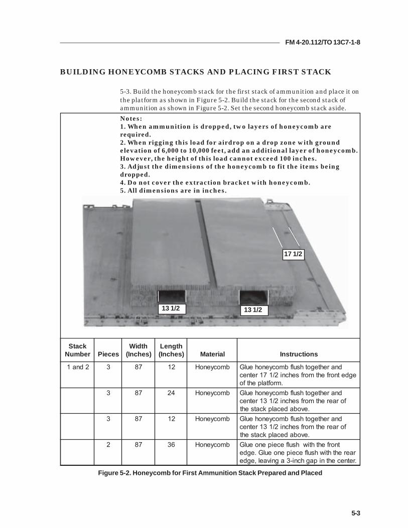
FM 4-20.112/TO 13C7-1-8
5-3
BUILDING HONEYCOMB STACKS AND PLACING FIRST STACK
5-3. Build the honeycomb stack for the first stack of ammunition and place it onthe platform as shown in Figure 5-2. Build the stack for the second stack ofammunition as shown in Figure 5-2. Set the second honeycomb stack aside.
Figure 5-2. Honeycomb for First Ammunition Stack Prepared and Placed
Notes:1. When ammunition is dropped, two layers of honeycomb arerequired.2. When rigging this load for airdrop on a drop zone with groundelevation of 6,000 to 10,000 feet, add an additional layer of honeycomb.However, the height of this load cannot exceed 100 inches.3. Adjust the dimensions of the honeycomb to fit the items beingdropped.4. Do not cover the extraction bracket with honeycomb.5. All dimensions are in inches.
13 1/2 13 1/2
17 1/2
kcatSrebmuN seceiP
htdiW)sehcnI(
htgneL)sehcnI( lairetaM snoitcurtsnI
2dna1 3 78 21 bmocyenoH dnarehtegothsulfbmocyenoheulGegdetnorfehtmorfsehcni2/171retnec
.mroftalpehtfo3 78 42 bmocyenoH dnarehtegothsulfbmocyenoheulG
foraerehtmorfsehcni2/131retnec.evobadecalpkcatseht
3 78 21 bmocyenoH dnarehtegothsulfbmocyenoheulGforaerehtmorfsehcni2/131retnec
.evobadecalpkcatseht2 78 63 bmocyenoH tnorfehthtiwhsulfeceipenoeulG
raerehthtiwhsulfeceipenoeulG.egde.retnecehtnipaghcni-3agnivael,egde

FM 4-20.112/TO 13C7-1-8
5-4
POSITIONING AND SECURING FIRST AMMUNITION STACK
5-4. Position and secure the first stack of 105-mm ammunition as shown inFigure 5-3.
1 Form two 30-foot lashings according to FM 4-20.102/NAVSEA SS400-AB-MMO-010/TO 13C7-1-5. Center them over the honeycomb as shown.
2 Place seven ammunition boxes on the rear side of stack 1. Let the boxes overhang the rearedge by 1 inch.
Figure 5-3. Ammunition Positioned and Secured
2
1
CAUTIONOnly ammunition listed in FM 4-20.153/MCRP 4-11.3B/TO 13C7-18-41 may beairdropped. Hazardous material must be packaged, marked, and labeled asrequired by AFMAN(I) 24-204/TM 38-250.

FM 4-20.112/TO 13C7-1-8
5-5
Figure 5-3. Ammunition Positioned and Secured (Continued)
3 Place a 36- by 87-inch piece of honeycomb over the boxes.
4 Place seven ammunition boxes flush with the first layer of boxes.
5 Place a 36- by 87-inch piece of honeycomb over the boxes placed in step 4.
6 Place three layers of boxes flush over the layers already placed.
7 Secure the pre-positioned lashing over the boxes with two D-rings and a load binder.
8 Place a 36- by 87-inch piece of honeycomb on edge against the boxes. Fit the honeycomb intothe 3-inch slot in the center of the honeycomb stack.
9 Place a 10- by 87-inch piece of honeycomb on edge over the piece placed in step 8.
9
87
6
5 43

FM 4-20.112/TO 13C7-1-8
5-6
10 Place 35 boxes of ammunition and two 36- by 87-inch pieces of honeycomb as described insteps 2 through 6 to complete stack 1.
11 Secure the pre-positioned lashing over the boxes with two D-rings and a load binder.
Figure 5-3. Ammunition Positioned and Secured (Continued)
10
11

FM 4-20.112/TO 13C7-1-8
5-7
Figure 5-4. Endboards for 105-mm Ammunition Constructed
CONSTRUCTING AND PLACING ENDBOARDS
5-5. Construct four endboards and place them on the load as shown inFigure 5-4.
55
90
10
10
10
12
52
3
2
3
2
3
2
3
HEIGHT OF THE LOAD
2
1
1 Cut two 3/4- by 48- by 90-inch and two 3/4- by 7- by 90-inch pieces of plywood. Nail the fourpieces flush together so that a single piece of 1 1/2- by 55- by 90-inch plywood results.
Note: On the endboard shown (Figure 5-5), the 7-inch piece is on the top. On theother side of the endboard shown, the 7-inch piece is at the bottom.
2 Make 2- by 3-inch cutouts as shown. Pad all cutouts with cellulose wadding and tape.
3 Repeat steps 1 and 2 making a total of four endboards.
4 Place an endboard against the front of the boxes and place one against the rear. Tie them inplace with a length of type III nylon cord. (Not shown)
Notes:1. This drawing is not to scale.2. All dimensions are in inches.
2
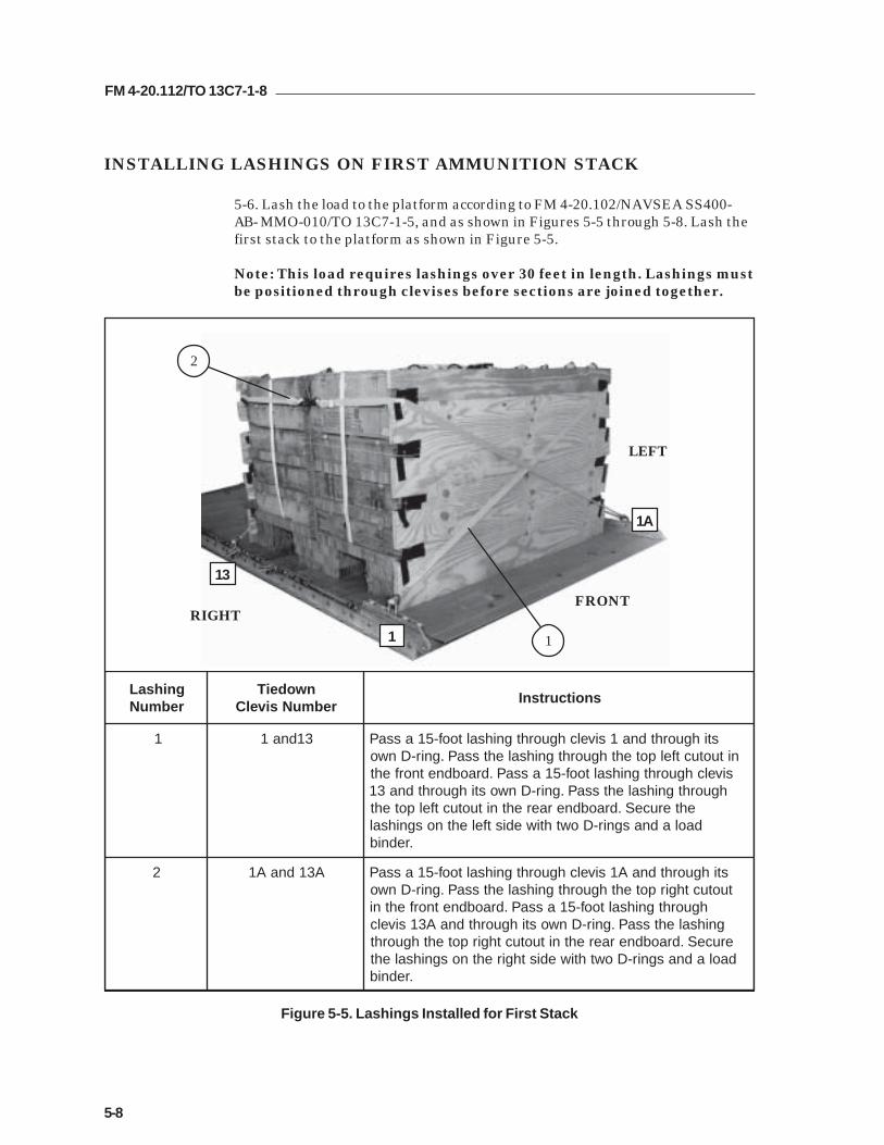
FM 4-20.112/TO 13C7-1-8
5-8
INSTALLING LASHINGS ON FIRST AMMUNITION STACK
5-6. Lash the load to the platform according to FM 4-20.102/NAVSEA SS400-AB- MMO-010/TO 13C7-1-5, and as shown in Figures 5-5 through 5-8. Lash thefirst stack to the platform as shown in Figure 5-5.
Note: This load requires lashings over 30 feet in length. Lashings mustbe positioned through clevises before sections are joined together.
Figure 5-5. Lashings Installed for First Stack
FRONTRIGHT
LEFT
1
13
2
1
1A
gnihsaLrebmuN
nwodeiTrebmuNsivelC
snoitcurtsnI
1 31dna1 stihguorhtdna1sivelchguorhtgnihsaltoof-51assaPnituotuctfelpotehthguorhtgnihsalehtssaP.gnir-Dnwo
sivelchguorhtgnihsaltoof-51assaP.draobdnetnorfehthguorhtgnihsalehtssaP.gnir-Dnwostihguorhtdna31
ehteruceS.draobdneraerehtnituotuctfelpotehtdaoladnasgnir-Dowthtiwedistfelehtnosgnihsal
.rednib
2 A31dnaA1 stihguorhtdnaA1sivelchguorhtgnihsaltoof-51assaPtuotucthgirpotehthguorhtgnihsalehtssaP.gnir-Dnwo
hguorhtgnihsaltoof-51assaP.draobdnetnorfehtnignihsalehtssaP.gnir-DnwostihguorhtdnaA31sivelc
eruceS.draobdneraerehtnituotucthgirpotehthguorhtdaoladnasgnir-Dowthtiwedisthgirehtnosgnihsaleht
.rednib

FM 4-20.112/TO 13C7-1-8
5-9
Figure 5-5. Lashings Installed for First Stack (Continued)
3
5
6
4
1110
8 5
gnihsaLrebmuN
nwodeiTrebmuNsivelC
snoitcurtsnI
3 A5dna5 hguorhtdnasesivelchtobhguorhtgnihsaltoof-03assaPehteruceS.draobdnetnorfehtnistuotucmottobeht
.rednibdaoladnasgnir-Dowthtiwtnorfehtnignihsal
4 A8dna8 hguorhtdnasesivelchtobhguorhtgnihsaltoof-54assaPehteruceS.draobdnetnorfehtnistuotucdnoceseht
daoladnasgnir-Dowthtiwedisthgirehtnognihsal.rednib
5 A01dna01 hguorhtdnasesivelchtobhguorhtgnihsaltoof-54assaPgnihsalehteruceS.draobdnetnorfehtnistuotucdrihteht
.rednibdaoladnasgnir-Dowthtiwedisthgirehtno
6 A11dna11 hguorhtdnasesivelchtobhguorhtgnihsaltoof-54assaPgnihsalehteruceS.draobdnetnorfehtnistuotucpoteht
.rednibdaoladnasgnir-Dowthtiwedisthgirehtno

FM 4-20.112/TO 13C7-1-8
5-10
Figure 5-5. Lashings Installed for First Stack (Continued)
47
9
7
8
9
gnihsaLrebmuN
nwodeiTrebmuNsivelC
snoitcurtsnI
7 A9dna9 hguorhtdnasesivelchtobhguorhtgnihsaltoof-03assaPehteruceS.draobdneraerehtnistuotucmottobeht
.rednibdaoladnasgnir-Dowthtiwedistfelehtnognihsal
8 A7dna7 hguorhtdnasesivelchtobhguorhtgnihsaltoof-54assaPgnihsalehteruceS.draobdneraerehtnistuotucdrihteht
.rednibdaoladnasgnir-Dowthtiwedistfelehtno
9 A4dna4 hguorhtdnasesivelchtobhguorhtgnihsaltoof-54assaPgnihsalehteruceS.draobdneraerehtnistuotucreppueht
.rednibdaoladnasgnir-Dowthtiwedistfelehtno

FM 4-20.112/TO 13C7-1-8
5-11
Figure 5-5. Lashings Installed for First Stack (Continued)
23612
1312
1110
gnihsaLrebmuN
nwodeiTrebmuNsivelC
snoitcurtsnI
01 A2dna2 stihguorhtdnasivelchcaehguorhtgnihsaltoof-51assaPerucesdnadaolehtrevosgnihsalhtobssaP.gnir-Dnwo
.rednibdaoladnasgnir-Dowthtiwpotnomeht
11 A3dna3 stihguorhtdnasivelchcaehguorhtgnihsaltoof-51assaPerucesdnadaolehtrevosgnihsalhtobssaP.gnir-Dnwo
.rednibdaoladnasgnir-Dowthtiwpotnomeht
21 A6dna6 stihguorhtdnasivelchcaehguorhtgnihsaltoof-51assaPerucesdnadaolehtrevosgnihsalhtobssaP.gnir-Dnwo
.rednibdaoladnasgnir-Dowthtiwpotnomeht
31 A21dna21 stihguorhtdnasivelchcaehguorhtgnihsaltoof-51assaPerucesdnadaolehtrevosgnihsalhtobssaP.gnir-Dnwo
.rednibdaoladnasgnir-Dowthtiwpotnomeht

FM 4-20.112/TO 13C7-1-8
5-12
POSITIONING AND SECURING SECOND AMMUNITION STACK
5-7. Place the first endboard for the second ammunition stack and pre-positionlashings as shown in Figure 5-6. Position the honeycomb stack, lashings, andammunition boxes as shown in Figure 5-7.
1 Stand an endboard against the rear endboard of the first stack. Temporaily secure it tothe rear endboard with type III nylon cord.
2 Pass a 15-foot lashing through clevis 14 and through its own D-ring. Pass the lashingthrough the top cutout on the left side of the endboard placed in step 1. Fold the free endand place it on top of the endboards.
3 Pass a 15-foot lashing through clevis 14A and through its own D-ring. Pass the lashingthrough the top cutout on the right side of the endboard placed in step 1. Fold the free endand place it on top of the endboards.
4 Pass a 30-foot lashing through clevises 19 and 19A and through the bottom slots of theendboards. Position the load binder on one side. Leave the load binder open.
5 Pass a 45-foot lashing through clevises 22 and 22A and through the second slots from thetop of the endboards. Position the load binder on one side. Leave the load binder open.
6 Pass a 45-foot lashing through clevises 23 and 23A and through the top slots of theendboards. Position the load binder on one side. Leave the load binder open.
Figure 5-6. Endboard for Second Stack Placed and Lashings Pre-positioned
23 22
19
14
23A19A
22A
3
4
2
6
5
4 2
1

FM 4-20.112/TO 13C7-1-8
5-13
1 Center the second honeycomb stack 17 1/2-inches from the rear edge of the platform.
2 Position two 30-foot lashings over the honeycomb as shown in Figure 5-3, step 1.
3 Stack honeycomb and 70 ammunition boxes as shown for the first stack.
4 Secure the lashings placed in step 2 over the boxes with two D-rings and a load binder.
5 Secure the load binders on the lashings placed in Figure 5-6, steps 4, 5, and 6 with twoD-rings and a load binder.
Figure 5-7. Honeycomb, Lashings, and Ammunition Placed for Second Stack
15
4
3

FM 4-20.112/TO 13C7-1-8
5-14
Figure 5-8. Lashings Installed for Second Stack
INSTALLING LASHINGS ON SECOND AMMUNITION STACK
5-8. Place the fourth endboard and lash the second ammunition stack to theplatform as shown in Figure 5-8. Make sure that the pre-positioned lashings aretaut and install additional lashings according to FM 4-20.102/NAVSEA SS400-AB-MMO-010/TO 13C7-1-5, and as shown in Figure 5-8.
25
15
14
gnihsaLrebmuN
nwodeiTrebmuNsivelC
snoitcurtsnI
41 52dna41 ,2pets,6-5erugiFnignihsaldenoitisop-erpehtssaPgnihsaltoof-51assaP.kcatsehtfoedistfelehtdnuora
ehtssaP.gnir-Dnwostihguorhtdna52sivelchguorht.draobdneraerehtnituotuctfelpotehthguorhtgnihsalsgnir-DowthtiwedistfelehtnosgnihsalowtehteruceS
.rednibdaoladna
51 A52dnaA41 ,3pets,6-5erugiFnignihsaldenoitisop-erpehtssaPgnihsaltoof-51assaP.kcatsehtfoedisthgirehtdnuoraehtssaP.gnir-DnwostihguorhtdnaA52sivelchguorht
.draobdneraerehtnituotucthgirpotehthguorhtgnihsalsgnir-DowthtiwedistfelehtnosgnihsalowtehteruceS
.rednibdaoladna

FM 4-20.112/TO 13C7-1-8
5-15
Figure 5-8. Lashings Installed for Second Stack (Continued)
21
1716
18
17
16
gnihsaLrebmuN
nwodeiTrebmuNsivelC
snoitcurtsnI
61 A61dna61 hguorhtdnasesivelchtobhguorhtgnihsaltoof-54assaPgnihsalehteruceS.draobdneraerehtnistuotucpoteht
.rednibdaoladnasgnir-Dowthtiwedisehtno
71 A71dna71 hguorhtdnasesivelchtobhguorhtgnihsaltoof-54assaP.draobdneraerehtnimottobehtmorfstuotucdrihteht
daoladnasgnir-DowthtiwedisehtnognihsalehteruceS.rednib
81 A12dna12 hguorhtdnasesivelchtobhguorhtgnihsaltoof-03assaPehteruceS.draobdneraerehtfostuotucmottobeht
.rednibdaoladnasgnir-Dowthtiwraerehttagnihsal

FM 4-20.112/TO 13C7-1-8
5-16
Figure 5-8. Lashings Installed for Second Stack (Continued)
152024 18
22
21 20 19
gnihsaLrebmuN
nwodeiTrebmuNsivelC
snoitcurtsnI
91 A51dna51 stihguorhtdnasivelchcaehguorhtgnihsaltoof-51assaP,daolehtrevothgirehtnognihsalehtssaP.gnir-Dnwo
-Dowthtiwedisehtnognihsaltfelehtottierucesdna.rednibdaoladnasgnir
02 A81dna81 stihguorhtdnasivelchcaehguorhtgnihsaltoof-51assaP,daolehtrevothgirehtnognihsalehtssaP.gnir-Dnwo
-Dowthtiwedisehtnognihsaltfelehtottierucesdna.rednibdaoladnasgnir
12 A02dna02 stihguorhtdnasivelchcaehguorhtgnihsaltoof-51assaP,daolehtrevothgirehtnognihsalehtssaP.gnir-Dnwo
-Dowthtiwedisehtnognihsaltfelehtottierucesdna.rednibdaoladnasgnir
22 A42dna42 stihguorhtdnasivelchcaehguorhtgnihsaltoof-51assaP,daolehtrevothgirehtnognihsalehtssaP.gnir-Dnwo
-Dowthtiwedisehtnognihsaltfelehtottierucesdna.rednibdaoladnasgnir
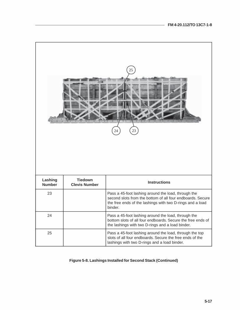
FM 4-20.112/TO 13C7-1-8
5-17
Figure 5-8. Lashings Installed for Second Stack (Continued)
gnihsaLrebmuN
nwodeiTrebmuNsivelC
snoitcurtsnI
32 ehthguorht,daolehtdnuoragnihsaltoof-54assaPeruceS.sdraobdneruofllafomottobehtmorfstolsdnoces
daoladnasgnir-Dowthtiwsgnihsalehtfosdneeerfeht.rednib
42 ehthguorht,daolehtdnuoragnihsaltoof-54assaPfosdneeerfehteruceS.sdraobdneruofllafostolsmottob
.rednibdaoladnasgnir-Dowthtiwsgnihsaleht
52 potehthguorht,daolehtdnuoragnihsaltoof-54assaPehtfosdneeerfehteruceS.sdraobdneruofllafostols
.rednibdaoladnasgnir-Dowthtiwsgnihsal
25
24 23
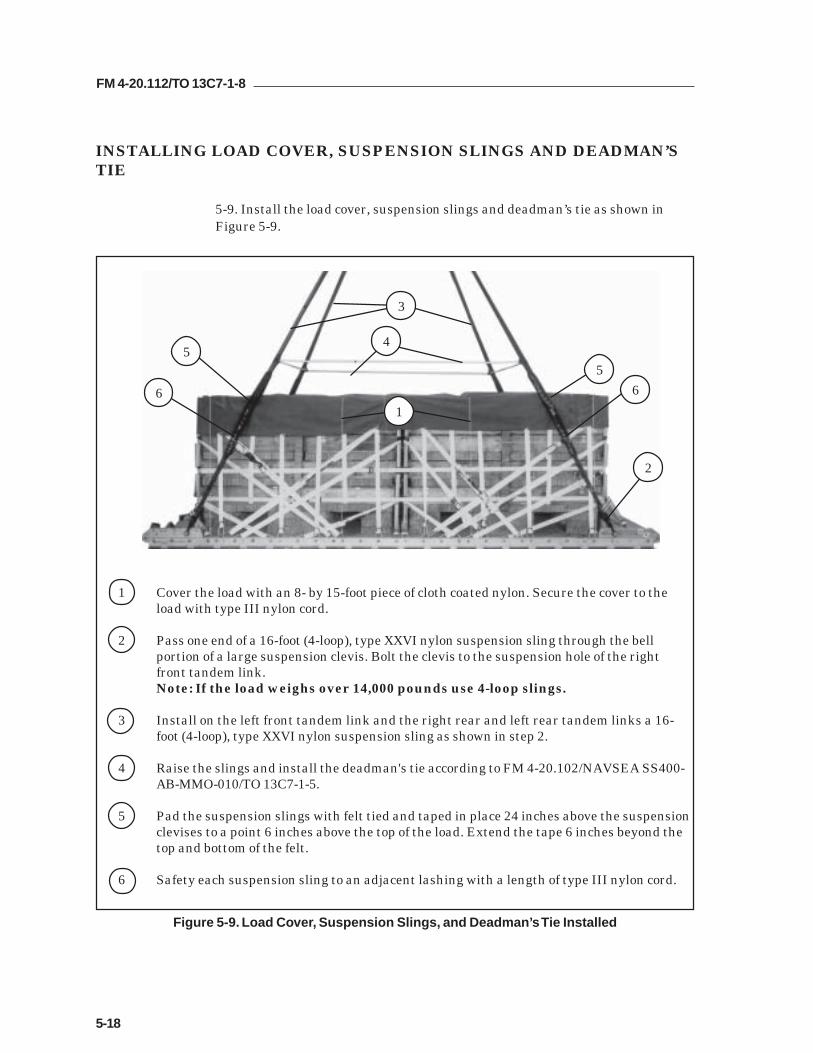
FM 4-20.112/TO 13C7-1-8
5-18
INSTALLING LOAD COVER, SUSPENSION SLINGS AND DEADMAN’STIE
5-9. Install the load cover, suspension slings and deadman’s tie as shown inFigure 5-9.
1 Cover the load with an 8- by 15-foot piece of cloth coated nylon. Secure the cover to theload with type III nylon cord.
2 Pass one end of a 16-foot (4-loop), type XXVI nylon suspension sling through the bellportion of a large suspension clevis. Bolt the clevis to the suspension hole of the rightfront tandem link.Note: If the load weighs over 14,000 pounds use 4-loop slings.
3 Install on the left front tandem link and the right rear and left rear tandem links a 16-foot (4-loop), type XXVI nylon suspension sling as shown in step 2.
4 Raise the slings and install the deadman's tie according to FM 4-20.102/NAVSEA SS400-AB-MMO-010/TO 13C7-1-5.
5 Pad the suspension slings with felt tied and taped in place 24 inches above the suspensionclevises to a point 6 inches above the top of the load. Extend the tape 6 inches beyond thetop and bottom of the felt.
6 Safety each suspension sling to an adjacent lashing with a length of type III nylon cord.
Figure 5-9. Load Cover, Suspension Slings, and Deadman’s Tie Installed
5
2
3
4
1
6
5
6

FM 4-20.112/TO 13C7-1-8
5-19
INSTALLING PARACHUTES
5-10. Compute the parachute requirements for the load being rigged. Prepareand install the cargo parachutes according to FM 4-20.102/ NAVSEA SS400-AB-MMO-010/TO 13C7-1-5 and as shown in Figure 5-10.
1 Prepare, position, and stow four G-11 cargo parachutes on the rear of the load accordingto FM 4-20.102/ NAVSEA SS400-AB-MMO-010/TO 13C7-1-5.
2 Install the rear cargo parachute restraints according to FM 4-20.102/ NAVSEA SS400-AB-MMO-010/TO 13C7-1-5 using type VIII nylon webbing to clevises 24 and 24A.
3 Install the center cargo parachute restraints according to FM 4-20.102/ NAVSEA SS400-AB-MMO-010/TO 13C7-1-5 using type VIII nylon webbing to clevises 27 and 27A.
4 Install the front cargo parachute restraints according to FM 4-20.102/ NAVSEA SS400-AB-MMO-010/TO 13C7-1-5 using type VIII nylon webbing to clevises 26 and 26A.
5 Install the parachute release straps according to FM 4-20.102/ NAVSEA SS400-AB-MMO-010/TO 13C7-1-5.
Figure 5-10. Cargo Parachutes Installed
1
2
3
4
5

FM 4-20.112/TO 13C7-1-8
5-20
INSTALLING THE RELEASE SYSTEM
5-11. Prepare, attach, and safety an M-2 cargo parachute release according toFM 4-20.102/NAVSEA SS400-AB-MMO-010/TO 13C7-1-5 and as shown inFigure 5-11.
1 Prepare and install the M-2 cargo parachute release according to FM 4-20.102/NAVSEA SS400-AB-MMO-010/TO 13C7-1-5. Place the assembly in front of the parachutesas shown.
2 Safety the release to convenient points on the load with type III nylon cord according toFM 4-20.102/NAVSEA SS400-AB-MMO-010/TO 13C7-1-5.
3 S-fold and tie any excess suspension slings with one turn of type I, 1/4-inch cottonwebbing.
Figure 5-11. Release System Installed
1
2
3

FM 4-20.112/TO 13C7-1-8
5-21
Figure 5-12. Extraction System Installed
INSTALLING THE EXTRACTION SYSTEM
5-12. Install the extraction system according to FM 4-20.102/NAVSEA SS400-AB-MMO-010/TO 13C7-1-5 and as shown in Figure 5-12.
1 Install the components of the EFTC according to FM 4-20.102/NAVSEA SS400-AB-MMO-010/TO 13C7-1-5. Use the front mounting holes for the EFTC brackets.
2 Install a 16-foot EFTC cable according to FM 4-20.102/NAVSEA SS400-AB-MMO-010/TO 13C7-1-5 and safety the cable to tie-down ring D8 with one turn of type I, 1/4-inchcotton webbing.
3 Attach a 9-foot (2-loop), type XXVI nylon sling according to FM 4-20.102/NAVSEA SS400-AB-MMO-010/TO 13C7-1-5 to be used as a deployment line. S-fold the excess and tie it intwo places with type I, 1/4-inch cotton webbing.
2
3
12
D8

FM 4-20.112/TO 13C7-1-8
5-22
PLACING EXTRACTION PARACHUTE
5-13. Select the extraction parachute and extraction line needed using the extractionline requirements table in FM 4-20.102/ NAVSEA SS400-AB-MMO-010/TO 13C7-1-5.Place the extraction parachute and line on the load for installation in the aircraft.
INSTALLING PROVISIONS FOR EMERGENCY RESTRAINTS
5-14. Select and install the provisions for the emergency aft restraints according tothe emergency aft restraint requirements table in FM 4-20.102/NAVSEA SS400-AB-MMO-010/TO 13C7-1-5.
MARKING RIGGED LOAD
5-15. Mark the rigged load according to FM 4-20.102/NAVSEA SS400-AB-MMO-010/TO 13C7-1-5, and as shown in Figure 5-13. Complete Shipper'sDeclaration for Dangerous Goods. If the load varies from the one shown, the weight,height, CB, and parachute requirements must be recomputed.
EQUIPMENT REQUIRED
5-16. Use the equipment listed in Table 5-1 to rig this load.

FM 4-20.112/TO 13C7-1-8
5-23
RIGGED LOAD DATA
Minimum Weight................................................................5,040 pounds
Maximum Weight...............................................................See paragraph 5-1
Height....................................................................................97 1/2 inches
Width....................................................................................108 inches
Length..................................................................................192 inches
Overhang: Front................................................................0 inches
Rear..................................................................0 inches
Center of Balance (CB)(from front edge of the platform)......................................106 inches
Extraction System (adds 18 inches to length of platform) EFTC
Figure 5-13. Supply Load Rigged on a 16-Foot Platform for Low-Velocity Airdrop
C B
CAUTIONMake the final rigger inspection required by AR 59-4 and FM 4-20.102/NAVSEASS400-AB-MMO-010/TO 13C7-1-5 before the load leaves the rigging site.

FM 4-20.112/TO 13C7-1-8
5-24
Table 5-1. Equipment Required for Rigging Typical Loads on a 16-Foot, Type V Platform forLow-Velocity Airdrop
National Stock Item Quantity Number
8040-00-273-8713 Adhesive paste, 1-gal. As required4030-00-090-5354 Clevis, suspension, 1-inch (large) 54030-00-678-8562 Clevis, 3/4-inch medium 68305-00-880-8155 Cloth, coated (nylon, type II, 17.0 oz, green, 60-in) As required4020-00-240-2146 Cord, nylon, type III, 550-lb. As required1670-00-434-5785 Coupling, airdrop extraction force transfer, w/16-ft. cable 11670-00-360-0328 Cover, clevis 48135-00-664-6958 Cushioning material (Cellulose wadding) As required8305-00-958-3685 Felt, 1/2-inch thick As required1670-01-183-2678 Leaf, extraction line (line bag) ( add 2 for C-17) 2
Line extraction:1670-01-062-6313 60-foot (3-loop), type XXVI (for C-130) 11670-01-107-7651 140-foot (3-loop), type XXVI (for C-5) 11670-01-107-7651 140-foot (3-loop), type XXVI, 21670-01-107-7651 140-foot (3-loop), type XXVI (for C-17) 11670-01-062-6313 60-foot (3-loop), type XXVI (for C-17), (drogue line) 1
Link assembly, two-point:5306-00-435-8994 Bolt, 1-inch diameter, 4-inches long (add 4 for C-5) 25310-00-232-5165 Nut, 1-inch (add 4 for C-5) 21670-00-003-1953 Plate, side, 3 3/4-inch 25365-00-007-3414 Spacer, large (add 4 for C-5) 25315-00-010-4657 Nail, (steel common 6d) As required1670-00-753-3928 Pad, energy-dissipating (honeycomb)
3- by 36- by 96-inches 21 sheets1670-01-016-7841 Parachute, cargo, G-11 4
Parachute, cargo, extraction:1670-00-040-8135 28-ft. 11670-01-063-3715 15-ft. (C-17 only) 1
Platform, airdrop, type V, 16-ft:1670-01-162-2372 Clevis assembly (type V) (60)1670-01-353-8424 Extraction bracket assembly (1)1670-01-247-2389 Link, suspension bracket, type V (2)1670-01-162-2381 Link, tandem, suspension link assembly (4)1670-01-097-8817 Release, cargo parachute, M-2 1
Sling, cargo, airdrop:1670-01-062-6308 16-ft. (4-loop), type XXVI 41670-01-062-6304 9-ft. (2-loop), type XXVI 11670-01-062-6302 20-ft. (2-loop), type XXVI 12

FM 4-20.112/TO 13C7-1-8
5-25
Table 5-1. Equipment Required for Rigging Typical Loads on a 16-Foot, Type V Platform forLow-Velocity Airdrop (Continued)
National Stock Item Quantity Number
5340-00-040-8219 Strap, parachute, release, multi-knife 27501-00-266-5016 Tape, adhesive, 2-inch As required7510-00-266-6710 Tape, masking As required1670-00-937-0271 Tiedown assembly, 15-ft. 761670-01-483-8259 Towplate release mechanism (H-block) (C-17 only) 1
Webbing:8305-00-268-2411 Cotton, 1/4-inch, type I As required8305-00-082-5752 Nylon, tubular, 1/2-inch As required8305-00-261-8585 Type VIII nylon As required

FM 4-20.112/TO 13C7-1-8
5-26
Section II
RIGGING 155-MILLIMETER (MM) AMMUNITION
DESCRIPTION OF LOAD
5-17. Ninety-six 155-mm projectiles and 72 powder canisters are rigged forlow-velocity airdrop on a 16-foot, type V airdrop platform. All 155-mmammunition packaged as shown and listed in FM 4-20.153/MCRP 4-11.3B/TO13C7-18-41, as certified for low-velocity airdrop, may be rigged using theseprocedures. The load uses three G-11 cargo parachutes. Each load must weighat least 5,040 pounds, including parachutes. Refer to FM 4-20.102/NAVSEASS400-AB-MMO-010/TO 13C7-1-5 for the weight limitations for the number ofparachutes to be used.
PREPARING PLATFORM
5-18. Prepare a 16-foot, type V platform as shown in Figure 5-14.

FM 4-20.112/TO 13C7-1-8
5-27
Step:
1. Inspect, or assemble and inspect, a 16-foot, type V platform as outlined in TM 10-1670-268-20&P/TO 13C7-52-22.
2. Install a tandem link to the front of each platform side rail using holes 1, 2, and 3.
3. Install a tandem link to the rear of each platform side rail using holes 30, 31, and32.
4. Install clevises on bushings 2 and 3 of each front tandem link.
5. Install clevises on bushings 1 and 3 of each rear tandem link.
6. Starting at the front of the right and left platform side rail, install clevises on thebushings bolted to holes 4, 6, 9, 10, 11, 12, 13, 15, 16, 17, 18, 19, 20, 22, 23, 24, 25,and 29.
7. Starting at the front of the platform, number the clevises 1 through 22 on the rightside, and 1A through 22A on the left side.
8. Label the tiedown rings according to FM 4-20.102/NAVSEA SS400-AB-MMO-010/TO 13C7-1-5.
Figure 5-14. Platform Prepared
CLEVISES 22 THROUGH 1
CLEVISES 22A THROUGH 1A
REAR FRONT
RIGHT
LEFT

FM 4-20.112/TO 13C7-1-8
5-28
10”
Figure 5-15. Honeycomb for First Ammunition Stack Prepared and Placed
BUILDING HONEYCOMB STACKS AND PLACING FIRST STACK
5-19. Build the honeycomb stack for the first stack of ammunition and place iton the platform as shown in Figure 5-15. Build the stack for the second stack ofammunition as shown in Figure 5-15. Set the second honeycomb stack aside.
kcatSrebmuN seceiP
htdiW)sehcnI(
htgneL)sehcnI( lairetaM snoitcurtsnI
2dna1 22
6381
4848
bmocyenoHbmocyenoH
gnolsehcni48esabreyalowtamroFsreyalehtetanretlA.ediwsehcni45dna
01kcatsehtretneC.bmocyenohfoehtfoegdetnorfehtmorfsehcni
.mroftalp8 21 5 bmocyenoH nobmocyenohfoseceipowtecalP
hcni-5ehthtiwesabehtforenrochcaefosedisthgirdnatfelehtgnicafsedis
.mroftalpeht
4 21 01 bmocyenoH gnolabmocyenohfoseceipowtretneChcni-01ehthtiwesabehtfoedishcaefosedisthgirdnatfelehtgnicafsedis
.mroftalpeht
61 21 01 bmocyenoH foseceipreyalowtehtecapsylnevEdnaretnecehtneewtebbmocyenoh
ehtneewtebsecapsehT.seceiprenroc.sehcni4eraseceip

FM 4-20.112/TO 13C7-1-8
5-29
Figure 5-16. Projectiles Placed on Honeycomb and Lashings Pre-positioned
POSITIONING AND SECURING FIRST AMMUNITION STACK
5-20. Set six sets of projectiles on the honeycomb and pre-position three lashingsas shown in Figure 5-16. Stow 36 powder canisters and secure them as shownin Figure 5-17.
1 Set three bundles of projectiles flush on the honeycomb on each side. Fit the skids at thebottom of the bundles into the slots in the honeycomb stack.
2 Center a 15-foot lashing on the base layer of honeycomb from left to right.
3 Place a 15-foot lashing 14 inches from each end of the stack in a right-to-left direction.
1
3
2
3

FM 4-20.112/TO 13C7-1-8
5-30
1 Center four powder canisters on each of the pre-positioned lashings in Figure 5-16, steps 2and 3. Alternate the ends of the canisters as shown.
2 Place a 24- by 24-inch piece of honeycomb over each group of four canisters.
3 Place a second layer of 12 canisters over the honeycomb placed in step 2.
4 Place a second layer of three 24- by 24-inch pieces of honeycomb over the second layer ofcanisters.
5 Place a third layer of canisters over the honeycomb placed in step 4.
6 Secure the three pre-positioned lashings over the canisters. Pad between the load bindersand canisters with cellulose wadding.
7 Center two 28- by 84-inch pieces of honeycomb over the canisters.
Figure 5-17. Canisters Stowed and Secured
1
23
4 5
6
7

FM 4-20.112/TO 13C7-1-8
5-31
38
60
4
6
6
12
22
3
2
3
2
3
2
3
HEIGHT OF THE LOAD
1
2
2
CONSTRUCTING ENDBOARDS
5-21. Construct four endboards as shown in Figure 5-18.
Notes:1. This drawing is not to scale.2. All dimensions are in inches.
Figure 5-18. Endboards for 155-mm Ammunition Constructed
1 Cut eight 3/4- by 60- by 38-inch pieces of plywood.
2 Make 2- by 3-inch cutouts as shown and number 1 through 4.
3 Nail two pieces of plywood flush together with 6d nails to make four endboards. Pad thecutouts with cellulose wadding and tape. (Not shown)
CAUTION The endboards must be the same height as the ends of the load.
#1
#2
#3
#4

FM 4-20.112/TO 13C7-1-8
5-32
Figure 5-19. Lashings Installed for First Stack
INSTALLING LASHINGS ON FIRST AMMUNITION STACK AND FIRSTAND SECOND ENDBOARDS
5-22. Lash the load to the platform according to FM 4-20.102/NAVSEA SS400-AB- MMO-010/TO 13C7-1-5, and as shown in Figures 5-19 and 5-20. Set anendboard against each end of the first ammunition stack. Lash the first andsecond endboards and the first ammunition stack to the platform as shown inFigure 5-19.
4678
1
23
4
gnihsaLrebmuN
nwodeiTrebmuNsivelC
snoitcurtsnI
1 A4dna4 hguorhtdnasesivelchtobhguorhtgnihsaltoof-03assaPgnihsalehteruceS.draobdnetsrifehtnituotucdrihteht
.rednibdaoladnasgnir-Dowthtiwtnorfehtni
2 A6dna6 hguorhtdnasesivelchtobhguorhtgnihsaltoof-03assaPgnihsalehteruceS.draobdnetsrifehtnituotucdnoceseht
.rednibdaoladnasgnir-Dowthtiwtnorfehtni
3 A7dna7 hguorhtdnasesivelchtobhguorhtgnihsaltoof-03assaPgnihsalehteruceS.draobdnednocesehtnituotucpoteht
.rednibdaoladnasgnir-Dowthtiwedistfelehtno
4 A8dna8 hguorhtdnasesivelchtobhguorhtgnihsaltoof-03assaP.draobdnednocesehtfopotehtmorftuotucdrihteht
dnasgnir-DowthtiwedisthgirehtnognihsalehteruceS.rednibdaola

FM 4-20.112/TO 13C7-1-8
5-33
Figure 5-19. Lashings Installed for First Stack (Continued)
121011
8
5
7
6
57
gnihsaLrebmuN
nwodeiTrebmuNsivelC
snoitcurtsnI
5 01dna1 ehthguorht,1sivelchguorhtgnihsaltoof-03assaPdna,draobdnetsrifehtfoedistfelehtnotuotucdnoces
ehtssaP.kcatsnoitinummaehtfoedistfelehtdnuoratfelehtnipotehtmorftuotucdnocesehthguorhtgnihsal
.01sivelchguorhtdnadraobdnednocesehtfoedisadnasgnir-DowthtiwedistfelehtnognihsalehteruceS
.rednibdaol
6 A01dnaA1 potehthguorht,A1sivelchguorhtgnihsaltoof-03assaPdnuoradna,draobdnetsrifehtfoedisthgirehtnotuotuc
gnihsalehtssaP.kcatsnoitinummaehtfoedisthgirehtfoedisthgirehtnipotehtmorftuotucdnocesehthguorht
ehteruceS.A01sivelchguorhtdnadraobdnednocesehtdaoladnasgnir-Dowthtiwedisthgirehtnognihsal
.rednib
7 11dna2 drihtehthguorht,2sivelchguorhtgnihsaltoof-03assaPdnuoradna,draobdnetsrifehtfoedistfelehtnotuotuc
gnihsalehtssaP.kcatsnoitinummaehtfoedistfelehtdnocesehtfoedistfelehtnotuotucdrihtehthguorht
ehtnognihsalehteruceS.11sivelchguorhtdnadraobdne.rednibdaoladnasgnir-Dowthtiwedistfel
8 A11dnaA2 drihtehthguorht,A2sivelchguorhtgnihsaltoof-03assaPdnuoradna,draobdnetsrifehtfoedisthgirehtnotuotuc
gnihsalehtssaP.kcatsnoitinummaehtfoedisthgirehtdnocesehtfoedisthgirehtnotuotucdrihtehthguorht
nognihsalehteruceS.A11sivelchguorhtdnadraobdne.rednibdaoladnasgnir-Dowthtiwedisthgireht

FM 4-20.112/TO 13C7-1-8
5-34
Figure 5-19. Lashings Installed for First Stack (Continued)
9 5 3
11 10 9
gnihsaLrebmuN
nwodeiTrebmuNsivelC
snoitcurtsnI
9 A3dna3 ehtrevodnasesivelchtobhguorhtgnihsaltoof-03assaPsgnir-DowthtiwpotnognihsalehteruceS.daolehtfopot
.rednibdaoladna
01 A5dna5 ehtrevodnasesivelchtobhguorhtgnihsaltoof-03assaPsgnir-DowthtiwpotnognihsalehteruceS.daolehtfopot
.rednibdaoladna
11 A9dna9 ehtrevodnasesivelchtobhguorhtgnihsaltoof-03assaPsgnir-DowthtiwpotnognihsalehteruceS.daolehtfopot
.rednibdaoladna

FM 4-20.112/TO 13C7-1-8
5-35
POSITIONING SECOND AMMUNITION STACK AND THIRD ANDFOURTH ENDBOARDS
5-23. Position and secure the second ammunition stack and its endboards asdescribed below.
a. Center the honeycomb for the second ammunition stack 6 inches fromthe rear edge of the platform.
b. Stow and secure six sets of projectiles and 36 powder canisters on thehoneycomb as shown in Figures 5-16 and 5-17.
c. Set an endboard against each end of the second ammunition stack.
LASHING SECOND AMMUNITION STACK AND THIRD AND FOURTHENDBOARDS
5-24. Lash the second ammunition stack and the third and fourth endboards tothe platform as shown in Figure 5-20.
Figure 5-20. Lashings Installed for Second Stack
19 17 16 15
15
14
13
12
gnihsaLrebmuN
nwodeiTrebmuNsivelC
snoitcurtsnI
21 A51dna51 hguorhtdnasesivelchtobhguorhtgnihsaltoof-03assaPgnihsalehteruceS.draobdnedrihtehtnituotucdrihteht
.rednibdaoladnasgnir-Dowthtiwtnorfehtni
31 A61dna61 hguorhtdnasesivelchtobhguorhtgnihsaltoof-03assaPehteruceS.draobdnedrihtehtnituotucdnoceseht
.rednibdaoladnasgnir-Dowthtiwtnorfehtnignihsal
41 A71dna71 hguorhtdnasesivelchtobhguorhtgnihsaltoof-03assaPgnihsalehteruceS.draobdnehtruofehtnituotucpoteht
.rednibdaoladnasgnir-Dowthtiwedistfelehtno
51 A91dna91 hguorhtdnasesivelchtobhguorhtgnihsaltoof-03assaP.draobdnehtruofehtfopotehtmorftuotucdrihteht
dnasgnir-DowthtiwedisthgirehtnognihsalehteruceS.rednibdaola

FM 4-20.112/TO 13C7-1-8
5-36
Figure 5-20. Lashings Installed for Second Stack (Continued)
121322 21
18
16
19 17
1816
gnihsaLrebmuN
nwodeiTrebmuNsivelC
snoitcurtsnI
61 12dna21 ehthguorht,21sivelchguorhtgnihsaltoof-03assaPdna,draobdnedrihtehtfoedistfelehtnotuotucdnoces
ehtssaP.kcatsnoitinummaehtfoedistfelehtdnuoratfelehtnipotehtmorftuotucdnocesehthguorhtgnihsaleruceS.12sivelchguorhtdnadraobdnehtruofehtfoedis
daoladnasgnir-Dowthtiwedistfelehtnognihsaleht.rednib
71 A12dnaA21 potehthguorht,A21sivelchguorhtgnihsaltoof-03assaPdnuoradna,draobdnedrihtehtfoedisthgirehtnotuotuc
gnihsalehtssaP.kcatsnoitinummaehtfoedisthgirehtfoedisthgirehtnipotehtmorftuotucdnocesehthguorht
ehteruceS.A12sivelchguorhtdnadraobdnehtruofehtdaoladnasgnir-Dowthtiwedisthgirehtnognihsal
.rednib
81 22dna31 drihtehthguorht,31sivelchguorhtgnihsaltoof-03assaPdnuoradna,draobdnedrihtehtfoedistfelehtnotuotuc
gnihsalehtssaP.kcatsnoitinummaehtfoedistfelehthtruofehtfoedistfelehtnotuotucdrihtehthguorht
ehtnognihsalehteruceS.22sivelchguorhtdnadraobdne.rednibdaoladnasgnir-Dowthtiwedistfel
91 A22dnaA31 ehthguorht,A31sivelchguorhtgnihsaltoof-03assaPdna,draobdnedrihtehtfoedisthgirehtnotuotucdrihtehtssaP.kcatsnoitinummaehtfoedisthgirehtdnuora
ehtfoedisthgirehtnotuotucdrihtehthguorhtgnihsalehteruceS.A22sivelchguorhtdnadraobdnehtruofdaoladnasgnir-Dowthtiwedisthgirehtnognihsal
.rednib

FM 4-20.112/TO 13C7-1-8
5-37
Figure 5-20. Lashings Installed for Second Stack (Continued)
20 1418
2221 20 24 23
gnihsaLrebmuN
nwodeiTrebmuNsivelC
snoitcurtsnI
02 A41dna41 ehtrevodnasesivelchtobhguorhtgnihsaltoof-03assaPsgnir-DowthtiwpotnognihsalehteruceS.daolehtfopot
.rednibdaoladna
12 A81dna81 ehtrevodnasesivelchtobhguorhtgnihsaltoof-03assaPsgnir-DowthtiwpotnognihsalehteruceS.daolehtfopot
.rednibdaoladna
22 A02dna02 ehtrevodnasesivelchtobhguorhtgnihsaltoof-03assaPsgnir-DowthtiwpotnognihsalehteruceS.daolehtfopot
.rednibdaoladna
32 ehthguorhtdaoleritneehtdnuoragnihsaltoof-54assaPnognihsalehteruceS.sdraobdneruofllanistuotucpot
.rednibdaoladnasgnir-Dowthtiwediseht
42 ehthguorhtdaoleritneehtdnuoragnihsaltoof-54assaPgnihsalehteruceS.sdraobdneruofllanistuotucmottob
.rednibdaoladnasgnir-Dowthtiwedisehtno

FM 4-20.112/TO 13C7-1-8
5-38
INSTALLING SUSPENSION SLINGS AND DEADMAN’S TIE
5-25. Install the suspension slings and deadman’s tie as shown in Figure 5-21.
1 Pass one end of a 16-foot (2-loop), type XXVI nylon suspension sling through the bellportion of a large suspension clevis. Bolt the clevis to the suspension hole of the rightfront tandem link.
2 Install on the front left tandem link and the right rear and left rear tandem links a 16-foot (2-loop), type XXVI nylon suspension sling as in step 1.
3 Raise the slings and install the deadman's tie according to FM 4-20.102/NAVSEA SS400-AB-MMO-010/TO 13C7-1-5.
Figure 5-21. Suspension Slings and Deadman’s Tie Installed
13
2

FM 4-20.112/TO 13C7-1-8
5-39
Figure 5-22. Cargo Parachutes Installed
INSTALLING PARACHUTES
5-26. Compute the parachute requirements for the load being rigged. Prepareand install the cargo parachutes according to FM 4-20.102/ NAVSEA SS400-AB-MMO-010/TO 13C7-1-5 and as shown in Figure 5-22.
1 Lay two 27- by 75-inch pieces of honeycomb side-by-side and flush with the rear edge ofthe ammunition stack. Tape the edges of the honeycomb and tie it to the load with type IIInylon cord.
2 Prepare, position, and stow three G-11 cargo parachutes according to FM 4-20.102/NAVSEA SS400-AB-MMO-010/TO 13C7-1-5 and place them on the honeycomb placed instep 1.
3 Install the rear cargo parachute restraints according to FM 4-20.102/ NAVSEA SS400-AB-MMO-010/TO 13C7-1-5 using type VIII nylon webbing to the second bushings on therear tandem links.
4 Install the front cargo parachute restraints according to FM 4-20.102/ NAVSEA SS400-AB-MMO-010/TO 13C7-1-5 using type VIII nylon webbing to bushings 27 and 27A.
5 Install the parachute release straps according to FM 4-20.102/ NAVSEA SS400-AB-MMO-010/TO 13C7-1-5.
1
2
3
3
4
5

FM 4-20.112/TO 13C7-1-8
5-40
INSTALLING THE RELEASE SYSTEM
5-27. Prepare, attach, and safety an M-1 cargo parachute release according toFM 4-20.102/NAVSEA SS400-AB-MMO-010/TO 13C7-1-5 and as shown inFigure 5-23.
1 Prepare and install the M-1 cargo parachute release according to FM 4-20.102/NAVSEA SS400-AB-MMO-010/TO 13C7-1-5. Place the assembly in front of the parachutesas shown.
2 Safety the release to convenient points on the load with type III nylon cord according toFM 4-20.102/NAVSEA SS400-AB-MMO-010/TO 13C7-1-5.
3 S-fold and tie any excess suspension slings with one turn of type I, 1/4-inch cottonwebbing.
4 Tie the two side sections of the deadman’s tie together in the center with a length oftype I, 1/4-inch cotton webbing.
Figure 5-23. Release System Installed
3
2
4
3
1

FM 4-20.112/TO 13C7-1-8
5-41
Figure 5-24. Extraction System Installed
INSTALLING THE EXTRACTION SYSTEM
5-28. Install the extraction system according to FM 4-20.102/NAVSEA SS400-AB-MMO-010/TO 13C7-1-5 and as shown in Figure 5-24.
1 Install the components of the EFTC according to FM 4-20.102/NAVSEA SS400-AB-MMO-010/TO 13C7-1-5. Use the front mounting holes for the EFTC brackets.
2 Install a 16-foot EFTC cable according to FM 4-20.102/NAVSEA SS400-AB-MMO-010/TO 13C7-1-5 and safety the cable to tie-down ring D8 with one turn of type I, 1/4-inchcotton webbing.
3 Attach a 9-foot (2-loop), type XXVI nylon sling according to FM 4-20.102/NAVSEA SS400-AB-MMO-010/TO 13C7-1-5 to be used as a deployment line. S-fold the excess and tie it intwo places with type I, 1/4-inch cotton webbing.
1
2
3
D8

FM 4-20.112/TO 13C7-1-8
5-42
PLACING EXTRACTION PARACHUTE
5-29. Select the extraction parachute and extraction line needed using the extractionline requirements table in FM 4-20.102/ NAVSEA SS400-AB-MMO-010/TO 13C7-1-5.Place the extraction parachute and line on the load for installation in the aircraft.
INSTALLING PROVISIONS FOR EMERGENCY RESTRAINTS
5-30. Select and install the provisions for the emergency aft restraints according tothe emergency aft restraint requirements table in FM 4-20.102/NAVSEA SS400-AB-MMO-010/TO 13C7-1-5.
MARKING RIGGED LOAD
5-31. Mark the rigged load according to FM 4-20.102/NAVSEA SS400-AB-MMO-010/TO 13C7-1-5, and as shown in Figure 5-25. Complete Shipper'sDeclaration for Dangerous Goods. If the load varies from the one shown, the weight,height, CB, and parachute requirements must be recomputed.
EQUIPMENT REQUIRED
5-32. Use the equipment listed in Table 5-2 to rig this load.

FM 4-20.112/TO 13C7-1-8
5-43
RIGGED LOAD DATA
Minimum Weight................................................................5,040 pounds
Maximum Weight...............................................................See paragraph 5-17
Height....................................................................................86 inches
Width....................................................................................108 inches
Length..................................................................................192 inches
Overhang: Front................................................................0 inches
Rear..................................................................0 inches
Center of Balance (CB)(from front edge of the platform)......................................101 inches
Extraction System (adds 18 inches to length of platform) EFTC
Figure 5-25. 155-mm Ammunition Rigged on a 16-Foot Platform for Low-Velocity Airdrop
C B
CAUTIONMake the final rigger inspection required by AR 59-4 and FM 4-20.102/NAVSEASS400-AB-MMO-010/TO 13C7-1-5 before the load leaves the rigging site.

FM 4-20.112/TO 13C7-1-8
5-44
Table 5-2. Equipment Required for Rigging 155-mm Ammunition on a 16-Foot, Type VPlatform for Low-Velocity Airdrop
National Stock Item Quantity Number
8040-00-273-8713 Adhesive paste, 1-gal. As required4030-00-090-5354 Clevis, suspension, 1-inch (large) 54030-00-678-8562 Clevis, 3/4-inch medium 48305-00-880-8155 Cloth, coated (nylon, type II, 17.0 oz, green, 60-in) As required4020-00-240-2146 Cord, nylon, type III, 550-lb. As required1670-00-434-5785 Coupling, airdrop extraction force transfer, w/16-ft. cable 11670-00-360-0328 Cover, clevis 38135-00-664-6958 Cushioning material (Cellulose wadding) As required8305-00-958-3685 Felt, 1/2-inch thick As required1670-01-183-2678 Leaf, extraction line (line bag) ( add 2 for C-17) 2
Line extraction:1670-01-062-6313 60-foot (3-loop), type XXVI (for C-130) 11670-01-107-7651 140-foot (3-loop), type XXVI (for C-5) 11670-01-107-7651 140-foot (3-loop), type XXVI, 21670-01-107-7651 140-foot (3-loop), type XXVI (for C-17) 11670-01-064-4452 60-foot (1-loop), type XXVI (for C-17), (drogue line) 1
Link assembly, two-point:5306-00-435-8994 Bolt, 1-inch diameter, 4-inches long (add 4 for C-5) 25310-00-232-5165 Nut, 1-inch (add 4 for C-5) 21670-00-003-1953 Plate, side, 3 3/4-inch 25365-00-007-3414 Spacer, large (add 4 for C-5) 25315-00-010-4657 Nail, (steel common 6d) As required1670-00-753-3928 Pad, energy-dissipating (honeycomb)
3- by 36- by 96-inches 13 sheets1670-01-016-7841 Parachute, cargo, G-11 3
Parachute, cargo, extraction:1670-01-063-3716 22-ft. 11670-01-063-3715 15-ft. (C-17 only) 1
Platform, airdrop, type V, 16-ft:5530-00-618-8073 Plywood, 3/4-inch As required1670-01-162-2372 Clevis assembly (type V) (44)1670-01-353-8424 Extraction bracket assembly (1)1670-01-162-2381 Link, tandem, suspension link assembly (4)1670-01-097-8816 Release, cargo parachute, M-1 1
Sling, cargo, airdrop:1670-01-062-6304 9-ft. (2-loop), type XXVI 11670-01-062-6307 16-ft. (2-loop), type XXVI 41670-01-062-6313 60-foot (3-loop), type XXVI 3

FM 4-20.112/TO 13C7-1-8
5-45
Table 5-2. Equipment Required for Rigging 155-mm Ammunition on a 16-Foot, Type VPlatform for Low-Velocity Airdrop (Continued)
National Stock Item Quantity Number
5340-00-040-8219 Strap, parachute, release, multi-knife 27501-00-266-5016 Tape, adhesive, 2-inch As required1670-00-937-0271 Tiedown assembly, 15-ft. 561670-01-483-8259 Towplate release mechanism (H-block) (C-17 only) 1
Webbing:8305-00-268-2411 Cotton, 1/4-inch, type I As required8305-00-082-5752 Nylon, tubular, 1/2-inch As required8305-00-261-8585 Type VIII nylon As required

FM 4-20.112/TO 13C7-1-8
5-46
Section III
RIGGING 20-MILLIMETER (MM) AMMUNITION
DESCRIPTION OF LOAD
5-33. Two hundred forty boxes of 20-mm ammunition are rigged forlow-velocity airdrop on a 16-foot, type V airdrop platform. All 20-mmammunition packaged as shown and listed in FM 4-20.153/MCRP 4-11.3B/TO13C7-18-41, as certified for low-velocity airdrop, may be rigged using theseprocedures. This load uses five G-11 cargo parachutes. Each load must weighat least 5,040 pounds, including parachutes. Refer to FM 4-20.102/NAVSEASS400-AB-MMO-010/TO 13C7-1-5 for the weight limitations for the number ofparachutes to be used.
PREPARING PLATFORM
5-34. Prepare a 16-foot, type V platform as shown in Figure 5-26.

FM 4-20.112/TO 13C7-1-8
5-47
Step:
1. Inspect, or assemble and inspect, a 16-foot, type V platform as outlined in TM 10-1670-268-20&P/TO 13C7-52-22.
2. Install a tandem link to the front of each platform side rail using holes 1, 2, and 3.
3. Install a tandem link to the rear of each platform side rail using holes 30, 31, and32.
4. Install clevises on bushings 2, 3, and 4 of each front tandem link.
5. Install clevises on bushings 1, 2, and 3 of each rear tandem link.
6. Starting at the front of the right and left platform side rail, install clevises on thebushings bolted to holes 5, 6, 7, 11, 15, 16, 17, 18, 22, 26, 27, and 28.Install triple clevises on holes 9, 12, 14, 19, 21, and 24 according to FM 4-20.102/NAVSEA SS400-AB-MMO-010/TO 13C7-1-5.
7. Starting at the front of the platform, number the clevises 1 through 30 on the rightside, and 1A through 30A on the left side.
8. Label the tiedown rings according to FM 4-20.102/NAVSEA SS400-AB-MMO-010/TO 13C7-1-5.
Figure 5-26. Platform Prepared
CLEVISES 30 THROUGH 1
CLEVISES 30A THROUGH 1A
REARFRONT
RIGHT
LEFT

FM 4-20.112/TO 13C7-1-8
5-48
BUILDING HONEYCOMB STACKS AND PLACING FIRST STACK
5-35. Build the honeycomb stack for the first stack of ammunition and place iton the platform as shown in Figure 5-27. Build the stack for the second stack ofammunition as shown in Figure 5-27. Set the second honeycomb stack aside.
1 Center two 15- by 75-inch pieces of honeycomb lengthwise on the platform, 19 inches fromthe front edge.
2 Place two 36- by 75-inch pieces of honeycomb flush on each side of the pieces placed instep 1.
3 Center a 30-foot lashing 10 inches from each end of the honeycomb.
4 Center a 30-foot lashing 26 inches from the front edge of the honeycomb, and another 30-foot lashing 26 inches from the rear.
Figure 5-27. Honeycomb for First Ammunition Stack Prepared and Placed
FRONTREAR
19”
21
4
3

FM 4-20.112/TO 13C7-1-8
5-49
POSITIONING AND SECURING FIRST AMMUNITION STACK
5-36. Set 120 boxes of 20-mm ammunition on the honeycomb and pre-positionedlashings. Secure the lashings as shown in Figure 5-28.
1 Set 40 boxes of ammunition on the honeycomb.
2 Place one layer of honeycomb cut to the dimensions in Figure 5-27, steps 1 and 2, overthe boxes.
3 Place 40 boxes of ammunition over the honeycomb placed in step 2.
4 Place a layer of honeycomb over the second layer of boxes.
5 Place a third layer of boxes over the honeycomb placed in step 4.
6 Secure each of the pre-positioned lashings in Figure 5-27, steps 3 and 4, on top of theboxes with two D-rings and a load binder.
Figure 5-28. First Ammunition Stack Placed and Secured
6 6
5
4
3
2
1

FM 4-20.112/TO 13C7-1-8
5-50
54
90
6
8
16
12
42
3
2
3
2
3
2
3
HEIGHT OF THE LOAD
1
2
2
Figure 5-29. Endboards for 20-mm Ammunition Constructed and Placed
1 Cut two 3/4- by 48- by 90-inch and two 3/4- by 6- by 90-inch pieces of plywood. Nail the fourpieces flush together so that a single piece of 1 1/2- by 54- by 90-inch plywood results.Construct three other endboards the same way.
Note: On the endboard shown, the 6-inch piece is at the bottom. On the otherside of the endboard shown, the 6-inch piece is at the top.
2 Make 2- by 3-inch cutouts as shown. Pad all cutouts with cellulose wadding and tape.
3 Place an endboard against the front of the boxes and place one against the rear. Tie them inplace with a length of type III nylon cord.
CONSTRUCTING AND PLACING ENDBOARDS
5-37. Construct four endboards as shown and place them on the load as shownin Figure 5-29.
Notes: 1. This drawing is not to scale. 2. All dimensions are in inches.
3
#1
#2
#3
#4

FM 4-20.112/TO 13C7-1-8
5-51
LASHING FIRST AMMUNITION STACK AND FIRST AND SECONDENDBOARDS
5-38. Cover the left and right upper edges of the stack of boxes with felt asshown in Figure 5-30. Lash the first and second endboards and the firstammunition stack to the platform as shown in Figure 5-31.
Note: This load requires lashings over 30 feet in length. Lashingsmust be positioned through clevises before sections are joinedtogether.
Figure 5-30. Boxes Padded with Felt
1
2
1 Center a piece of felt, 75 inches long, over the left and right upper corners of the stack ofboxes.
2 Tape the felt in place.
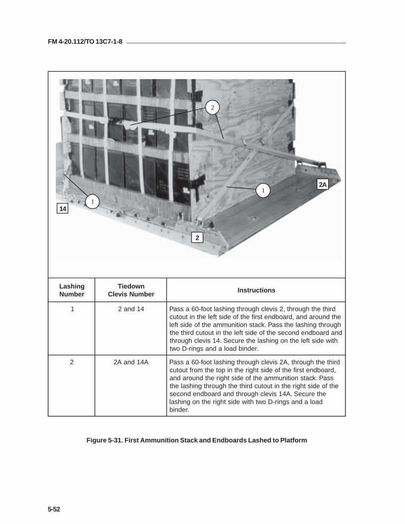
FM 4-20.112/TO 13C7-1-8
5-52
Figure 5-31. First Ammunition Stack and Endboards Lashed to Platform
14
2
2A1
2
1
gnihsaLrebmuN
nwodeiTrebmuNsivelC
snoitcurtsnI
1 41dna2 drihtehthguorht,2sivelchguorhtgnihsaltoof-06assaPehtdnuoradna,draobdnetsrifehtfoedistfelehtnituotuchguorhtgnihsalehtssaP.kcatsnoitinummaehtfoedistfeldnadraobdnednocesehtfoedistfelehtnituotucdrihteht
htiwedistfelehtnognihsalehteruceS.41sivelchguorht.rednibdaoladnasgnir-Dowt
2 A41dnaA2 drihtehthguorht,A2sivelchguorhtgnihsaltoof-06assaP,draobdnetsrifehtfoedisthgirehtnipotehtmorftuotuc
ssaP.kcatsnoitinummaehtfoedisthgirehtdnuoradnaehtfoedisthgirehtnituotucdrihtehthguorhtgnihsaleht
ehteruceS.A41sivelchguorhtdnadraobdnednocesdaoladnasgnir-Dowthtiwedisthgirehtnognihsal
.rednib

FM 4-20.112/TO 13C7-1-8
5-53
Figure 5-31. First Ammunition Stack and Endboards Lashed to Platform (Continued)
15
3
3A
34
4
3
gnihsaLrebmuN
nwodeiTrebmuNsivelC
snoitcurtsnI
3 51dna3 ehthguorht,3sivelchguorhtgnihsaltoof-06assaPdna,draobdnetsrifehtfoedistfelehtnituotucmottobehtssaP.kcatsnoitinummaehtfoedistfelehtdnuoraehtfoedistfelehtnituotucmottobehthguorhtgnihsal
ehteruceS.51sivelchguorhtdna,draobdnednoces.rednibdaoladnasgnir-Dowthtiwedistfelehtnognihsal
4 A51dnaA3 ehthguorht,A3sivelchguorhtgnihsaltoof-06assaPdna,draobdnetsrifehtfoedisthgirehtnituotucmottobehtssaP.kcatsnoitinummaehtfoedisthgirehtdnuoraehtfoedisthgirehtnituotucmottobehthguorhtgnihsal
ehteruceS.A51sivelchguorhtdna,draobdnednocesdaoladnasgnir-Dowthtiwedisthgirehtnognihsal
.rednib

FM 4-20.112/TO 13C7-1-8
5-54
Figure 5-31. First Ammunition Stack and Endboards Lashed to Platform (Continued)
8 7 6 5 4
7
9
5
8
6
gnihsaLrebmuN
nwodeiTrebmuNsivelC
snoitcurtsnI
5 A4dna4 stihguorhtdnasivelchcaehguorhtgnihsaltoof-51assaPhtiwsexobehtfopotnosgnihsalehteruceS.gnir-Dnwo
.rednibdaoladnasgnir-Dowt
6 A5dna5 hguorhtdnasesivelchtobhguorhtgnihsaltoof-54assaPehteruceS.draobdnednocesehtnistuotucpoteht
daoladnasgnir-Dowthtiwdaolehtfoedisehtnognihsal.rednib
7 A6dna6 hguorhtdnasesivelchtobhguorhtgnihsaltoof-54assaPehteruceS.draobdnednocesehtnistuotucdrihteht
adnasgnir-Dowthtiwdaolehtfoedisehtnognihsal.rednibdaol
8 A7dna7 stihguorhtdnasivelchcaehguorhtgnihsaltoof-51assaPhtiwsexobehtfopotnosgnihsalehteruceS.gnir-Dnwo
.rednibdaoladnasgnir-Dowt
9 A8dna8 hguorhtdnasesivelchtobhguorhtgnihsaltoof-03assaPehteruceS.draobdnednocesehtnistuotucmottobeht
daoladnasgnir-Dowthtiwdaolehtfoedisehtnognihsal.rednib

FM 4-20.112/TO 13C7-1-8
5-55
Figure 5-31. First Ammunition Stack and Endboards Lashed to Platform (Continued)
910111213
10
11
13
1214
gnihsaLrebmuN
nwodeiTrebmuNsivelC
snoitcurtsnI
01 A9dna9 hguorhtdnasesivelchtobhguorhtgnihsaltoof-03assaPehteruceS.draobdnetsrifehtnistuotucmottobeht
daoladnasgnir-Dowthtiwdaolehtfoedisehtnognihsal.rednib
11 A01dna01 hguorhtdnasesivelchtobhguorhtgnihsaltoof-54assaPgnihsalehteruceS.draobdnetsrifehtnituotucdrihteht
.rednibdaoladnasgnir-Dowthtiwdaolehtfoedisehtno
21 A11dna11 stihguorhtdnasivelchcaehguorhtgnihsaltoof-51assaPhtiwsexobehtfopotnognihsalehteruceS.gnir-Dnwo
.rednibdaoladnasgnir-Dowt
31 A21dna21 hguorhtdnasesivelchtobhguorhtgnihsaltoof-54assaPnognihsalehteruceS.draobdnetsrifehtnituotucpoteht
.rednibdaoladnasgnir-Dowthtiwdaolehtfoediseht
41 A31dna31 stihguorhtdnasivelchcaehguorhtgnihsaltoof-51assaPhtiwsexobehtfopotnosgnihsalehteruceS.gnir-Dnwo
.rednibdaoladnasgnir-Dowt
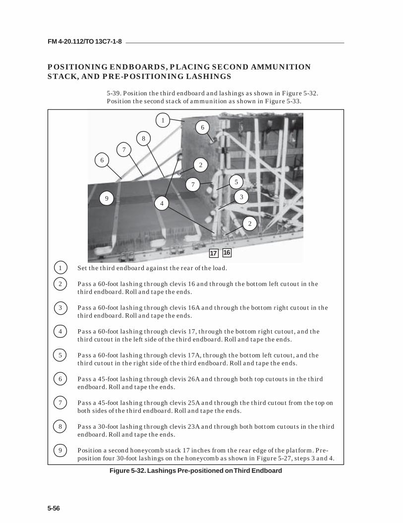
FM 4-20.112/TO 13C7-1-8
5-56
POSITIONING ENDBOARDS, PLACING SECOND AMMUNITIONSTACK, AND PRE-POSITIONING LASHINGS
5-39. Position the third endboard and lashings as shown in Figure 5-32.Position the second stack of ammunition as shown in Figure 5-33.
Figure 5-32. Lashings Pre-positioned on Third Endboard
1 Set the third endboard against the rear of the load.
2 Pass a 60-foot lashing through clevis 16 and through the bottom left cutout in thethird endboard. Roll and tape the ends.
3 Pass a 60-foot lashing through clevis 16A and through the bottom right cutout in thethird endboard. Roll and tape the ends.
4 Pass a 60-foot lashing through clevis 17, through the bottom right cutout, and thethird cutout in the left side of the third endboard. Roll and tape the ends.
5 Pass a 60-foot lashing through clevis 17A, through the bottom left cutout, and thethird cutout in the right side of the third endboard. Roll and tape the ends.
6 Pass a 45-foot lashing through clevis 26A and through both top cutouts in the thirdendboard. Roll and tape the ends.
7 Pass a 45-foot lashing through clevis 25A and through the third cutout from the top onboth sides of the third endboard. Roll and tape the ends.
8 Pass a 30-foot lashing through clevis 23A and through both bottom cutouts in the thirdendboard. Roll and tape the ends.
9 Position a second honeycomb stack 17 inches from the rear edge of the platform. Pre-position four 30-foot lashings on the honeycomb as shown in Figure 5-27, steps 3 and 4.
16
2
4
8
7
6
2
3
5
17 16
7
9

FM 4-20.112/TO 13C7-1-8
5-57
Figure 5-33. Second Stack of Ammunition Positioned
1 Stow 120 boxes of ammunition on the honeycomb as shown in Figure 5-28.
2 Secure each of the pre-positioned lashings on top of the boxes with two D-rings and a loadbinder.
3 Pad the left and right upper edges of the boxes with felt as shown in Figure 5-30. (Notshown)
4 Place the fourth endboard against the rear of the load. Safety tie it to convenient points fortemporary support. (Not shown)
1
2

FM 4-20.112/TO 13C7-1-8
5-58
LASHING SECOND AMMUNITION STACK AND THIRD AND FOURTHENDBOARDS
5-40. Lash the third and fourth endboards and the second ammunition stack tothe platform as shown in Figure 5-34.
Figure 5-34. Second Ammunition Stack and Endboards Lashed to Platform
15
16
15
16
28
28A
gnihsaLrebmuN
nwodeiTrebmuNsivelC
snoitcurtsnI
51 82dna61 ,2pets,23-5erugiFnignihsaldenoitisop-erpehtssaPtfelmottobehthguorht,sexobehtfoedistfelehtdnuora
.82sivelchguorhtdnadraobdnehtruofehtnituotucadnasgnir-DowthtiwedistfelehtnognihsalehteruceS
.rednibdaol
61 A82dnaA61 ,3pets,23-5erugiFnignihsaldenoitisop-erpehtssaPmottobehthguorht,sexobehtfoedisthgirehtdnuora
.A82sivelchguorhtdnadraobdnehtruofehtnituotucthgirdnasgnir-DowthtiwedisthgirehtnognihsalehteruceS
.rednibdaola

FM 4-20.112/TO 13C7-1-8
5-59
Figure 5-34. Second Ammunition Stack and Endboards Lashed to Platform (Continued)
17
18
17
29A
29
17
gnihsaLrebmuN
nwodeiTrebmuNsivelC
snoitcurtsnI
71 92dna71 ,4pets,23-5erugiFnignihsaldenoitisop-erpehtssaPtuotucdrihtehthguorht,sexobehtfoedistfelehtdnuora
sivelchguorhtdnadraobdnehtruofehtfoedistfelehtnisgnir-DowthtiwedistfelehtnognihsalehteruceS.92
.rednibdaoladna
81 A92dnaA71 ,5pets,23-5erugiFnignihsaldenoitisop-erpehtssaPtuotucdrihtehthguorht,sexobehtfoedisthgirehtdnuora
sivelchguorhtdnadraobdnehtruofehtfoedisthgirehtnisgnir-DowthtiwedisthgirehtnognihsalehteruceS.A92
.rednibdaoladna

FM 4-20.112/TO 13C7-1-8
5-60
Figure 5-34. Second Ammunition Stack and Endboards Lashed to Platform (Continued)
232526
21
2019
gnihsaLrebmuN
nwodeiTrebmuNsivelC
snoitcurtsnI
91 A32dna32 8pets,23-5erugiFnignihsaldenoitisop-erpehtssaPhtiwedisthgirehtnognihsalehteruceS.32sivelchguorht
.rednibdaoladnasgnir-Dowt
02 A52dna52 7pets,23-5erugiFnignihsaldenoitisop-erpehtssaPhtiwedisthgirehtnognihsalehteruceS.52sivelchguorht
.rednibdaoladnasgnir-Dowt
12 A62dna62 6pets,23-5erugiFnignihsaldenoitisop-erpehtssaPhtiwedisthgirehtnognihsalehteruceS.62sivelchguorht
.rednibdaoladnasgnir-Dowt

FM 4-20.112/TO 13C7-1-8
5-61
Figure 5-34. Second Ammunition Stack and Endboards Lashed to Platform (Continued)
22
23
24
22 21 19
gnihsaLrebmuN
nwodeiTrebmuNsivelC
snoitcurtsnI
22 A91dna91 hguorhtdnasesivelchtobhguorhtgnihsaltoof-54assaPgnihsalehteruceS.draobdnehtruofehtnistuotucpoteht
.rednibdaoladnasgnir-Dowthtiwedisehtno
32 A12dna12 hguorhtdnasesivelchtobhguorhtgnihsaltoof-54assaPehteruceS.draobdnehtruofehtnistuotucdrihteht
.rednibdaoladnasgnir-Dowthtiwedisehtnognihsal
42 A22dna22 hguorhtdnasesivelchtobhguorhtgnihsaltoof-03assaPehteruceS.draobdnehtruofehtnistuotucmottobeht
.rednibdaoladnasgnir-Dowthtiwedisehtnognihsal

FM 4-20.112/TO 13C7-1-8
5-62
Figure 5-34. Second Ammunition Stack and Endboards Lashed to Platform (Continued)
28 27 26 25
27 24 20 18
gnihsaLrebmuN
nwodeiTrebmuNsivelC
snoitcurtsnI
52 A81dna81 stihguorhtdnasivelchcaehguorhtgnihsaltoof-51assaPsgnir-DowthtiwpotnognihsalehteruceS.gnir-Dnwo
.rednibdaoladna
62 A02dna02 stihguorhtdnasivelchcaehguorhtgnihsaltoof-51assaPsgnir-DowthtiwpotnognihsalehteruceS.gnir-Dnwo
.rednibdaoladna
72 A42dna42 stihguorhtdnasivelchcaehguorhtgnihsaltoof-51assaPsgnir-DowthtiwpotnognihsalehteruceS.gnir-Dnwo
.rednibdaoladna
82 A72dna72 stihguorhtdnasivelchcaehguorhtgnihsaltoof-51assaPsgnir-DowthtiwpotnognihsalehteruceS.gnir-Dnwo
.rednibdaoladna

FM 4-20.112/TO 13C7-1-8
5-63
gnihsaLrebmuN
nwodeiTrebmuNsivelC
snoitcurtsnI
92 03dna1 potehthguorht,1sivelchguorhtgnihsaltoof-57assaPehtdnuoradna,draobdnetsrifehtfoedistfelehtnituotuc
gnihsalehtssaP.skcatsnoitinummahtobfoedistfelhtruofehtfoedistfelehtnituotucpotehthguorht
ehtnognihsalehteruceS.03sivelchguorhtdnadraobdne.rednibdaoladnasgnir-Dowthtiwedistfel
03 A03dnaA1 potehthguorht,A1sivelchguorhtgnihsaltoof-57assaPdnuoradna,draobdnetsrifehtfoedisthgirehtnituotuc
gnihsalehtssaP.skcatsnoitinummahtobfoedisthgirehthtruofehtfoedisthgirehtnituotucpotehthguorht
nognihsalehteruceS.A03sivelchguorhtdnadraobdne.rednibdaoladnasgnir-Dowthtiwedisthgireht
Figure 5-34. Second Ammunition Stack and Endboards Lashed to Platform (Continued)
30
29 29
30 1
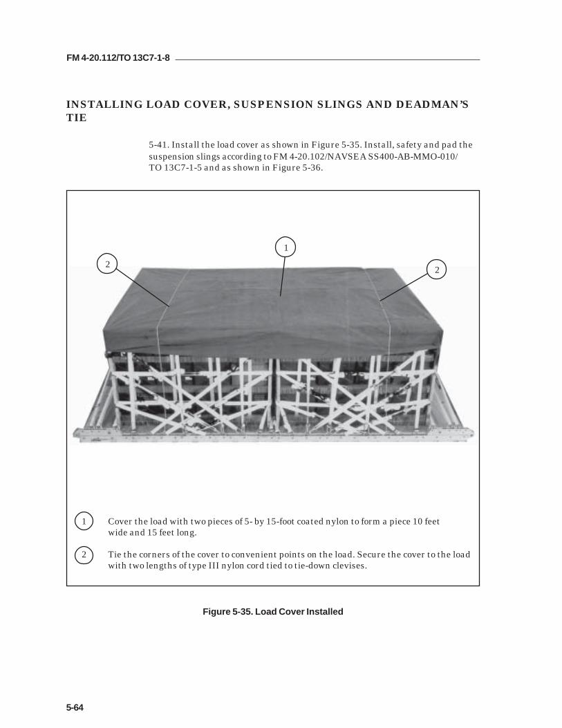
FM 4-20.112/TO 13C7-1-8
5-64
INSTALLING LOAD COVER, SUSPENSION SLINGS AND DEADMAN’STIE
5-41. Install the load cover as shown in Figure 5-35. Install, safety and pad thesuspension slings according to FM 4-20.102/NAVSEA SS400-AB-MMO-010/TO 13C7-1-5 and as shown in Figure 5-36.
1 Cover the load with two pieces of 5- by 15-foot coated nylon to form a piece 10 feetwide and 15 feet long.
2 Tie the corners of the cover to convenient points on the load. Secure the cover to the loadwith two lengths of type III nylon cord tied to tie-down clevises.
Figure 5-35. Load Cover Installed
2
1
2

FM 4-20.112/TO 13C7-1-8
5-65
Figure 5-36. Suspension Slings and Deadman’s Tie Installed
1 Pass one end of a 16-foot (4-loop), type XXVI nylon suspension sling through the bellportion of a large suspension clevis. Bolt the clevis to the suspension hole of the rightfront tandem link.
2 Install on the left front tandem link and the right rear and left rear tandem links a 16-foot (4-loop), type XXVI nylon suspension sling as in step 1.
3 Raise the slings and install the deadman's tie according to FM 4-20.102/NAVSEA SS400-AB-MMO-010/TO 13C7-1-5.
4 Pad the suspension slings with felt tied and taped in place 24 inches above the suspensionclevises to 8 inches above the top of the load. Extend the tape 2 inches beyond the top andbottom of the felt.
5 Tie a single length of 1/2-inch tubular nylon webbing between the right front and left rearsuspension slings at the same level as the deadman’s tie. Tie the right rear and left frontsuspension slings together in the same way.
1
2
3
45

FM 4-20.112/TO 13C7-1-8
5-66
INSTALLING PARACHUTES
5-42. Compute the parachute requirements for the load being rigged. Prepareand install the cargo parachutes according to FM 4-20.102/ NAVSEA SS400-AB-MMO-010/TO 13C7-1-5 and as shown in Figure 5-37.
1 Install five G-11 cargo parachutes at the rear of the load.
2 Tie the rear parachute restraint strap to platform bushings 29 and 29A.
3 Tie the front parachute restraint strap to clevises 21 and 21A.
4 Install the parachute release straps according to FM 4-20.102/ NAVSEA SS400-AB-MMO-010/TO 13C7-1-5.
Figure 5-37. G-11 Cargo Parachutes Installed
21
2
3
1
4

FM 4-20.112/TO 13C7-1-8
5-67
INSTALLING THE RELEASE SYSTEM
5-43. Prepare, attach, and safety an M-2 cargo parachute release according toFM 4-20.102/NAVSEA SS400-AB-MMO-010/TO 13C7-1-5 and as shown inFigure 5-38.
1 Prepare and install the M-2 cargo parachute release according to FM 4-20.102/NAVSEA SS400-AB-MMO-010/TO 13C7-1-5. Place the assembly in front of the parachutesas shown.
2 Safety the release to convenient points on the load with type III nylon cord according toFM 4-20.102/NAVSEA SS400-AB-MMO-010/TO 13C7-1-5.
3 S-fold and tie any excess suspension slings with one turn of type I, 1/4-inch cottonwebbing.
Figure 5-38. Release System Installed
2
1
3

FM 4-20.112/TO 13C7-1-8
5-68
Figure 5-39. Extraction System Installed
INSTALLING THE EXTRACTION SYSTEM
5-44. Install the extraction system according to FM 4-20.102/NAVSEA SS400-AB-MMO-010/TO 13C7-1-5 and as shown in Figure 5-39.
1 Install the components of the EFTC according to FM 4-20.102/NAVSEA SS400-AB-MMO-010/TO 13C7-1-5. Use the front mounting holes for the EFTC brackets.
2 Install a 16-foot EFTC cable according to FM 4-20.102/NAVSEA SS400-AB-MMO-010/TO 13C7-1-5 and safety the cable to tie-down ring D8 with one turn of type I, 1/4-inchcotton webbing.
3 Attach a 9-foot (2-loop), type XXVI nylon sling according to FM 4-20.102/NAVSEA SS400-AB-MMO-010/TO 13C7-1-5 to be used as a deployment line. S-fold the excess and tie it intwo places with type I, 1/4-inch cotton webbing.
D8
2
1
3

FM 4-20.112/TO 13C7-1-8
5-69
PLACING EXTRACTION PARACHUTE
5-45. Select the extraction parachute and extraction line needed using the extractionline requirements table in FM 4-20.102/ NAVSEA SS400-AB-MMO-010/TO 13C7-1-5.Place the extraction parachute and line on the load for installation in the aircraft.
INSTALLING PROVISIONS FOR EMERGENCY RESTRAINTS
5-46. Select and install the provisions for the emergency aft restraints according tothe emergency aft restraint requirements table in FM 4-20.102/NAVSEA SS400-AB-MMO-010/TO 13C7-1-5.
MARKING RIGGED LOAD
5-47. Mark the rigged load according to FM 4-20.102/NAVSEA SS400-AB-MMO-010/TO 13C7-1-5, and as shown in Figure 5-40. Complete Shipper'sDeclaration for Dangerous Goods. If the load varies from the one shown, the weight,height, CB, and parachute requirements must be recomputed.
EQUIPMENT REQUIRED
5-48. Use the equipment listed in Table 5-3 to rig this load.

FM 4-20.112/TO 13C7-1-8
5-70
RIGGED LOAD DATA
Minimum Weight................................................................5,040 pounds
Maximum Weight...............................................................See paragraph 5-33
Height....................................................................................92 inches
Width....................................................................................108 inches
Length..................................................................................192 inches
Overhang: Front................................................................0 inches
Rear..................................................................0 inches
Center of Balance (CB)(from front edge of the platform)......................................91 inches
Extraction System (adds 18 inches to length of platform) EFTC
Figure 5-40. 20-mm Ammunition Rigged on a 16-Foot Platform for Low-Velocity Airdrop
C B
CAUTIONMake the final rigger inspection required by AR 59-4 and FM 4-20.102/NAVSEASS400-AB-MMO-010/TO 13C7-1-5 before the load leaves the rigging site.

FM 4-20.112/TO 13C7-1-8
5-71
Table 5-3. Equipment Required for Rigging 20-mm Ammunition on a 16-Foot, Type VPlatform for Low-Velocity Airdrop
National Stock Item Quantity Number
8040-00-273-8713 Adhesive paste, 1-gal. As required4030-00-090-5354 Clevis, suspension, 1-inch (large) 78305-00-880-8155 Cloth, coated (nylon, type II, 17.0 oz, green, 60-in) As required4020-00-240-2146 Cord, nylon, type III, 550-lb. As required1670-00-434-5785 Coupling, airdrop extraction force transfer, w/16-ft. cable 11670-00-360-0328 Cover, clevis 58135-00-664-6958 Cushioning material (Cellulose wadding) As required8305-00-958-3685 Felt, 1/2-inch thick As required1670-01-183-2678 Leaf, extraction line (line bag) ( add 2 for C-17) 2
Line extraction:1670-01-062-6313 60-foot (3-loop), type XXVI (for C-130) 11670-01-107-7651 140-foot (3-loop), type XXVI, 21670-01-107-7651 140-foot (3-loop), type XXVI (for C-17) 11670-01-064-4452 60-foot (1-loop), type XXVI (for C-17), (drogue line) 1
Link assembly, two-point:5306-00-435-8994 Bolt, 1-inch diameter, 4-inches long (add 4 for C-5) 25310-00-232-5165 Nut, 1-inch (add 4 for C-5) 21670-00-003-1953 Plate, side, 3 3/4-inch 25365-00-007-3414 Spacer, large (add 4 for C-5) 25315-00-010-4657 Nail, (steel common 6d) As required1670-00-753-3928 Pad, energy-dissipating (honeycomb)
3- by 36- by 96-inches 20 sheets1670-01-016-7841 Parachute, cargo, G-11 5
Parachute, cargo, extraction:1670-01-063-3715 15-ft. (C-17 only) 11670-00-040-8135 28-ft. 1
Platform, airdrop, type V, 16-ft:5530-00-618-8073 Plywood, 3/4-inch As required1670-01-162-2372 Clevis assembly (type V) (72)1670-01-353-8424 Extraction bracket assembly (1)1670-01-162-2381 Link, tandem, suspension link assembly (4)1670-01-097-8817 Release, cargo parachute, M-2 1
Sling, cargo, airdrop:1670-01-062-6304 9-ft. (2-loop), type XXVI 11670-01-062-6307 16-ft. (2-loop), type XXVI 41670-01-062-6311 120-ft.(2-loop), type XXVI 5

FM 4-20.112/TO 13C7-1-8
5-72
Table 5-3. Equipment Required for Rigging 20-mm Ammunition on a 16-Foot, Type VPlatform for Low-Velocity Airdrop (Continued)
National Stock Item Quantity Number
5340-00-040-8219 Strap, parachute, release, multi-knife 27501-00-266-5016 Tape, adhesive, 2-inch As required1670-00-937-0271 Tiedown assembly, 15-ft. 1061670-01-483-8259 Towplate release mechanism (H-block) (C-17 only) 1
Webbing:8305-00-268-2411 Cotton, 1/4-inch, type I As required8305-00-082-5752 Nylon, tubular, 1/2-inch As required8305-00-261-8585 Type VIII nylon As required

FM 4-20.112/TO 13C7-1-8
5-73
Section IV
RIGGING MASS SUPPLY BOX
DESCRIPTION OF LOAD
5-49. Two mass supply boxes are rigged for low-velocity airdrop on a 16-foot,type V airdrop platform. Loads may include any bulk items of general supplythat can be packed into the box without shifting the load. Each load mustweigh at least 5,040 pounds, including parachutes. Refer to FM 4-20.102/NAVSEA SS400-AB-MMO-010/TO 13C7-1-5 for the weight limitations for thenumber of parachutes to be used.
PREPARING PLATFORM
5-50. Prepare a 16-foot, type V platform as shown in Figure 5-41.

FM 4-20.112/TO 13C7-1-8
5-74
Step:
1. Inspect, or assemble and inspect, a 16-foot, type V platform as outlined in TM 10-1670-268-20&P/TO 13C7-52-22.
2. Install a tandem link to the front of each platform side rail using holes 1, 2, and 3.
3. Install a tandem link to the rear of each platform side rail using holes 30, 31, and32.
4. Install clevises on bushings 1 and 2 of each front tandem link.
5. Install clevises on bushings 2 and 3 of each rear tandem link.
6. Starting at the front of the right and left platform side rail, install clevises on thebushings bolted to holes 7, 8, 9, 10, 11, 13, 15, 16, 17, 18, 19, 21, 22, 23, 24, 25, 26,and 27. Install triple clevises on bushings 5 and 28.
7. Starting at the front of the platform, number the clevises 1 through 26 on the rightside, and 1A through 26A on the left side.
8. Label the tiedown rings according to FM 4-20.102/NAVSEA SS400-AB-MMO-010/TO 13C7-1-5.
Figure 5-41. Platform Prepared
CLEVISES 26 THROUGH 1
CLEVISES 26A THROUGH 1A
REAR FRONT
RIGHT
LEFT

FM 4-20.112/TO 13C7-1-8
5-75
PLACING LASHINGS ON PLATFORM
5-51. Use twelve 15-foot tiedown lashings, and position the lashings on theplatform as shown in Figure 5-42.
1 Pass the free end of a 15-foot tiedown lashing through tiedown ring A2 and through its ownD-ring. Pass the free end over the right rail. Repeat for tie-down rings A3, A4, A5, A6, andA7.
2 Pass the free end of a 15-foot tiedown lashing through tiedown ring B2 and through its ownD-ring. Pass the free end over the left rail. Repeat for tie-down rings B3, B4, B5, B6, and B7.
Figure 5-42. Lashings Pre-positioned on Platform
A2A3A4A5A6A7
B7 B6 B5 B4 B3 B21
2

FM 4-20.112/TO 13C7-1-8
5-76
Figure 5-43. Box Ends Constructed
CONSTRUCTING AND FORMING STORAGE BOX COMPONENTS
5-52. Construct the individual components of a storage box as shown in Figures5-43, 5-44, and 5-45. Partially assemble the first box for loading asshown in Figure 5-46.
Notes:1. This drawing is not to scale.2. All dimensions are in inches.3. Use 8d nails.
92
85
48
3 1/2
1 Cut four 3/4-by 48- by 92-inch pieces of plywood.
2 Nail a 2- by 4- by 85-inch piece of lumber along the top and bottom edges of each of thefour end pieces with 8d nails as shown. Allow the plywood to extend past the lumber 3 1/2inches on each side.
1
1
2

FM 4-20.112/TO 13C7-1-8
5-77
Notes: 1. This drawing is not to scale. 2. All dimensions are in inches.
3. Use 8d nails.
1 Cut four 3/4- by 48- by 90-inch pieces of plywood. Face the finished sides of the plywoodup.
2 Make 2- by 3-inch cutouts as shown in each of the four sides. Face the 12-inch cutout tothe right on two pieces, and to the left on the other two.
3 Nail a 2- by 4- by 84 1/2-inch piece of lumber on edge along the top and bottom interioredges of each of the four sides with 8d nails. Allow the plywood to extend past the lumber2 3/4 inches on each end at the top. Overhang at the bottom is 2 3/4 inches at the small-notched end and 3/4 inches at the larger notched end.
4 Cut six pieces of 2- by 4- by 45-inch lumber for each of the four sides. Nail a piece of thislumber between each of the pieces of lumber placed in step 3 flush with the ends. Spacethe four remaining pieces as shown and nail them in place.
90
6
3
2
9
12
12
48
45
2 3/414 1/2 17 17 17 3/4
2
1
443
3
Figure 5-44. Box Sides Constructed
12

FM 4-20.112/TO 13C7-1-8
5-78
Notes:1. This drawing is not to scale.2. All dimensions are in inches.3. Use 8d nails.
Figure 5-45. Top of Boxes Constructed
1 Cut a full sheet of 3/4-inch plywood to 48 by 86 inches. Cut a second sheet to 45 1/2 by 86inches. Lay them side-by-side to make a piece 86 by 93 1/2 inches.
2 Space three 2- by 4- by 85-inch pieces of lumber evenly across the two pieces of plywood1/2-inch from the top and bottom. Allow 4 1/4 inches of plywood to overhang on each endof the lumber. Nail the lumber and the plywood together.
3 Repeat steps 1 and 2 above to make the top for the second box. (Not shown)
PLYWOOD3/4 X 45 1/2 X 86
PLYWOOD3/4 X 48 X 86
1
1
2

FM 4-20.112/TO 13C7-1-8
5-79
Figure 5-46. Box Partially Assembled for Loading
1 Assemble the box on the platform. Fit each end of the box between the sides with the leftand right of each end flush against the inside vertical lumber uprights on the sides.
2 Nail the pieces together with 8d nails through the front side of the box.
3 Be sure that the front box is centered on the platform and that the front edges of the sidesof the box are even with the front edge of the platform. (Not shown)
RIGHT FRONT
FRONT RIGHT
REAR
1
2
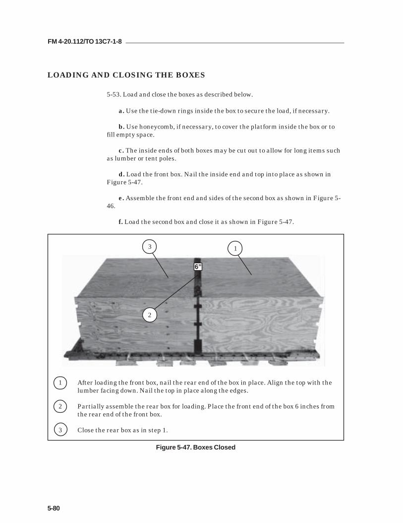
FM 4-20.112/TO 13C7-1-8
5-80
LOADING AND CLOSING THE BOXES
5-53. Load and close the boxes as described below.
a. Use the tie-down rings inside the box to secure the load, if necessary.
b. Use honeycomb, if necessary, to cover the platform inside the box or tofill empty space.
c. The inside ends of both boxes may be cut out to allow for long items suchas lumber or tent poles.
d. Load the front box. Nail the inside end and top into place as shown inFigure 5-47.
e. Assemble the front end and sides of the second box as shown in Figure 5-46.
f. Load the second box and close it as shown in Figure 5-47.
Figure 5-47. Boxes Closed
1 After loading the front box, nail the rear end of the box in place. Align the top with thelumber facing down. Nail the top in place along the edges.
2 Partially assemble the rear box for loading. Place the front end of the box 6 inches fromthe rear end of the front box.
3 Close the rear box as in step 1.
6”
2
13

FM 4-20.112/TO 13C7-1-8
5-81
INSTALLING LASHINGS
5-54. Install the lashings and secure pre-positioned lashings for the boxes asshown in Figures 5-48 through 5-57.
Notes:1. Pad the cutouts in the box sides with cellulose wadding. Tape thewadding in place.2. This load requires lashings over 30 feet in length. Lashings must bepositioned through clevises before sections are joined together.
Figure 5-48. Lashings 1 Through 5 Installed
35789
4
5
3
2
1
gnihsaLrebmuN
nwodeiTrebmuNsivelC
snoitcurtsnI
1 A3dna3 hguorhtdnasesivelchtobhguorhtgnihsaltoof-03assaPtnorfehtnignihsalehteruceS.stuotuctnorfmottobeht
.rednibdaoladnasgnir-Dowthtiw
2 A8dna8 hguorhtdnasesivelchtobhguorhtgnihsaltoof-54assaPtnorfehtnignihsalehteruceS.stuotuctnorfelddimeht
.rednibdaoladnasgnir-Dowthtiw
3 A9dna9 hguorhtdnasesivelchtobhguorhtgnihsaltoof-54assaPhtiwtnorfehtnignihsalehteruceS.stuotuctnorfreppueht
.rednibdaoladnasgnir-Dowt
4 A5dna5 hguorhtdnasesivelchtobhguorhtgnihsaltoof-54assaPhtiwedisehtnognihsalehteruceS.stuotucraerpoteht
.rednibdaoladnasgnir-Dowt
5 A7dna7 hguorhtdnasesivelchtobhguorhtgnihsaltoof-54assaPedisehtnognihsalehteruceS.stuotucraermottobeht
.rednibdaoladnasgnir-Dowthtiw

FM 4-20.112/TO 13C7-1-8
5-82
Figure 5-49. Lashings 6 Through 8 Installed
8 7 6
4610
gnihsaLrebmuN
nwodeiTrebmuNsivelC
snoitcurtsnI
6 A4dna4 stihguorhtdnasivelchcaehguorhtgnihsaltoof-51assaPowthtiwxobehtfopotnosgnihsalehteruceS.gnir-Dnwo
.rednibdaoladnasgnir-D
7 A6dna6 stihguorhtdnasivelchcaehguorhtgnihsaltoof-51assaPowthtiwxobehtfopotnosgnihsalehteruceS.gnir-Dnwo
.rednibdaoladnasgnir-D
8 A01dna01 stihguorhtdnasivelchcaehguorhtgnihsaltoof-51assaPowthtiwxobehtfopotnosgnihsalehteruceS.gnir-Dnwo
.rednibdaoladnasgnir-D

FM 4-20.112/TO 13C7-1-8
5-83
Figure 5-50. Pre-positioned Lashings Secured
1 Pass the ends of the pre-positioned lashings in tie-down rings A2 and B2 to the top of theload. Secure the lashings on top of the load with two D-rings and a load binder.
2 Secure the pre-positioned lashings in tie-down rings A3 and B3 in the same way.
3 Secure the pre-positioned lashings in tie-down rings A4 and B4 in the same way.
21
3

FM 4-20.112/TO 13C7-1-8
5-84
Figure 5-51. Lashings 9 and 10 Installed
9
9
10
11
1
1A
gnihsaLrebmuN
nwodeiTrebmuNsivelC
snoitcurtsnI
9 11dna1 potehthguorht,1sivelchguorhtgnihsaltoof-06assaPtfelehtdnuoradnaxobtsrifehtfoedistfelehtnituotuc
tfelpotehthguorhtgnihsalehtssaP.xobehtfoedissivelchguorhtdnaxobtsrifehtfodneraerehtnotuotuc
sgnir-DowthtiwedistfelehtnognihsalehteruceS.11.rednibdaoladna
01 A11dnaA1 potehthguorht,A1sivelchguorhtgnihsaltoof-06assaPehtdnuoradna,xobtsrifehtfoedisthgirehtnituotuc
thgirpotehthguorhtgnihsalehtssaP.xobehtfoedisthgirsivelchguorhtdnaxobtsrifehtfodneraerehtnotuotuc
sgnir-DowthtiwedisthgirehtnognihsalehteruceS.A11.rednibdaoladna

FM 4-20.112/TO 13C7-1-8
5-85
Figure 5-52. Lashings 11 and 12 Installed
2A
2
12
11
12
11
11
gnihsaLrebmuN
nwodeiTrebmuNsivelC
snoitcurtsnI
11 21dna2 ehthguorht,2sivelchguorhtgnihsaltoof-06assaPtsrifehtfotnorfehtnistuotuctfelelddimdnathgirmottob
gnihsalehtssaP.xobehtfoedistfelehtdnuoradna,xobtsrifehtfodneraerehtnotuotuctfelelddimehthguorhttfelehtnognihsalehteruceS.21sivelchguorhtdnaxob
.rednibdaoladnasgnir-Dowthtiwedis
21 A21dnaA2 ehthguorht,A2sivelchguorhtgnihsaltoof-06assaPtsrifehtfotnorfehtnistuotucthgirelddimdnatfelmottobgnihsalehtssaP.xobehtfoedisthgirehtdnuoradna,xobtsrifehtfodneraerehtnotuotucthgirelddimehthguorht
ehtnognihsalehteruceS.A21sivelchguorhtdnaxob.rednibdaoladnasgnir-Dowthtiwedisthgir

FM 4-20.112/TO 13C7-1-8
5-86
Figure 5-53. Lashings 13 Through 18 Installed
18
17
1615 14
13
24 22 21 19 18 17
gnihsaLrebmuN
nwodeiTrebmuNsivelC
snoitcurtsnI
31 A81dna81 hguorhtdnasesivelchtobhguorhtgnihsaltoof-03assaPeruceS.xobdnocesehtfotnorfehtnostuotucelddimeht
.rednibdaoladnasgnir-Dowthtiwedisehtnognihsaleht
41 A91dna91 hguorhtdnasesivelchtobhguorhtgnihsaltoof-03assaPeruceS.xobdnocesehtfotnorfehtnostuotucelddimeht
.rednibdaoladnasgnir-Dowthtiwedisehtnognihsaleht
51 A12dna12 hguorhtdnasesivelchtobhguorhtgnihsaltoof-54assaPehteruceS.xobdnocesehtfotnorfehtnostuotucpoteht
.rednibdaoladnasgnir-Dowthtiwedisehtnognihsal
61 A71dna71 hguorhtdnasesivelchtobhguorhtgnihsaltoof-54assaPhtiwraerehtnignihsalehteruceS.stuotucraerpoteht
.rednibdaoladnasgnir-Dowt
71 A22dna22 hguorhtdnasesivelchtobhguorhtgnihsaltoof-03assaPhtiwraerehtnignihsalehteruceS.stuotucraerelddimeht
.rednibdaoladnasgnir-Dowt
81 A42dna42 hguorhtdnasesivelchtobhguorhtgnihsaltoof-03assaPraerehtnignihsalehteruceS.stuotucraermottobeht
.rednibdaoladnasgnir-Dowthtiw

FM 4-20.112/TO 13C7-1-8
5-87
Figure 5-54. Pre-positioned Lashings Secured
1 Pass the ends of the pre-positioned lashings in tie-down rings A5 and B5 to the top of theload. Secure the lashings on top of the load with two D-rings and a load binder.
2 Pass the ends of the pre-positioned lashings in tie-down rings A6 and B6 to the top of theload. Secure the lashings on top of the load with two D-rings and a load binder.
3 Pass the ends of the pre-positioned lashings in tie-down rings A7 and B7 to the top of theload. Secure the lashings on top of the load with two D-rings and a load binder.
32
1

FM 4-20.112/TO 13C7-1-8
5-88
Figure 5-55. Lashings 19 Through 22 Installed
22
2120
19
23 20 16 15
gnihsaLrebmuN
nwodeiTrebmuNsivelC
snoitcurtsnI
91 A51dna51 stihguorhtdnasivelchcaehguorhtgnihsaltoof-51assaPowthtiwxobehtfopotnosgnihsalehteruceS.gnir-Dnwo
.rednibdaoladnasgnir-D
02 A61dna61 stihguorhtdnasivelchcaehguorhtgnihsaltoof-51assaPowthtiwxobehtfopotnosgnihsalehteruceS.gnir-Dnwo
.rednibdaoladnasgnir-D
12 A02dna02 stihguorhtdnasivelchcaehguorhtgnihsaltoof-51assaPowthtiwxobehtfopotnosgnihsalehteruceS.gnir-Dnwo
.rednibdaoladnasgnir-D
22 A32dna32 stihguorhtdnasivelchcaehguorhtgnihsaltoof-51assaPowthtiwxobehtfopotnosgnihsalehteruceS.gnir-Dnwo
.rednibdaoladnasgnir-D

FM 4-20.112/TO 13C7-1-8
5-89
Figure 5-56. Lashings 23 and 24 Installed
23
24
2313
25
25A
gnihsaLrebmuN
nwodeiTrebmuNsivelC
snoitcurtsnI
32 52dna31 potehthguorht,31sivelchguorhtgnihsaltoof-06assaPehtdnuoradnaxobdnocesehtfoedistfelehtnituotuctfelpotehthguorhtgnihsalehtssaP.xobehtfoedistfel
hguorhtdnaxobdnocesehtfoedisraerehtnotuotuc-DowthtiwedistfelehtnognihsalehteruceS.52sivelc
.rednibdaoladnasgnir
42 A52dnaA31 potehthguorht,A31sivelchguorhtgnihsaltoof-06assaPehtdnuoradna,xobdnocesehtfoedisthgirehtnituotuc
thgirpotehthguorhtgnihsalehtssaP.xobehtfoedisthgirhguorhtdnaxobdnocesehtfoedisraerehtnotuotuc
owthtiwedisthgirehtnognihsalehteruceS.A52sivelc.rednibdaoladnasgnir-D

FM 4-20.112/TO 13C7-1-8
5-90
Figure 5-57. Lashings 25 and 26 Installed
26
2525
26A
26
14
gnihsaLrebmuN
nwodeiTrebmuNsivelC
snoitcurtsnI
52 62dna41 ehthguorht,41sivelchguorhtgnihsaltoof-06assaPdnaxobdnocesehtfoedistfelehtnituotucelddim
hguorhtgnihsalehtssaP.xobehtfoedistfelehtdnuoraxobdnocesehtfoedisraerehtnotuotucelddimtfelehtedistfelehtnognihsalehteruceS.62sivelchguorhtdna
.rednibdaoladnasgnir-Dowthtiw
62 A62dnaA41 ehthguorht,A41sivelchguorhtgnihsaltoof-06assaPdna,xobdnocesehtfoedisthgirehtnituotucelddim
hguorhtgnihsalehtssaP.xobehtfoedisthgirehtdnuoraxobdnocesehtfoedisraerehtnotuotucelddimthgireht
thgirehtnognihsalehteruceS.A62sivelchguorhtdna.rednibdaoladnasgnir-Dowthtiwedis

FM 4-20.112/TO 13C7-1-8
5-91
INSTALLING LOAD COVER, SUSPENSION SLINGS AND DEADMAN’STIE
5-55. Install the load cover, suspension slings and deadman’s tie as shown inFigure 5-58.
1 Cover the rear third of the load with a 60- by 96-inch piece of cloth coated nylon. Securethe cover to the adjacent lashings with type III nylon cord.
2 Pass one end of a 16-foot (4-loop), type XXVI nylon suspension sling through the bellportion of a large suspension clevis. Bolt the clevis to the suspension hole of the rightfront tandem link.
3 Install on the left front tandem link and the right rear and left rear tandem links a 16-foot (4-loop), type XXVI nylon suspension sling as in step 2.
4 Raise the slings and install the deadman's tie according to FM 4-20.102/NAVSEA SS400-AB-MMO-010/TO 13C7-1-5.
5 Pad the suspension slings with felt tied and tape in place 36 inches above the suspensionclevises to 8 inches above the top of the load. Extend the tape 6 inches beyond the top andbottom of the felt.
6 Tie the front suspension slings together over the top of the load with a single length oftype III nylon cord. Tie the rear suspension slings the same way.
7 Place two 92- by 5 1/2-inch pieces of honeycomb between the two boxes above the topcutouts. Tie the honeycomb in place using type III nylon cord to convenient places on theload.
Figure 5-58. Load Cover, Suspension Slings, and Deadman’s Tie Installed
25
6
7
4
3
1
5

FM 4-20.112/TO 13C7-1-8
5-92
INSTALLING PARACHUTES
5-56. Consult FM 4-20.102/NAVSEA SS400-AB-MMO-010/TO 13C7-1-5 for thenumber of cargo parachutes required for the weight of the load. Four G-11 cargoparachutes are shown here. Install the cargo parachutes according to FM 4-20.102/NAVSEA SS400-AB-MMO-010/TO 13C7-1-5 and as shown inFigure 5-59.
Figure 5-59. Four G-11 Cargo Parachutes Installed
1 Install the cargo parachutes at the rear of the load.
2 Tie the front parachute restraint strap to clevises 25 and 25A.
3 Tie the center parachute restraint strap to clevises 21 and 21A.
4 Tie the rear parachute restraint strap to clevises 19 and 19A.
5 Install two multicut parachute release straps according to FM 4-20.102/ NAVSEA SS400-AB-MMO-010/TO 13C7-1-5.
5
1
43
2
25 21 19
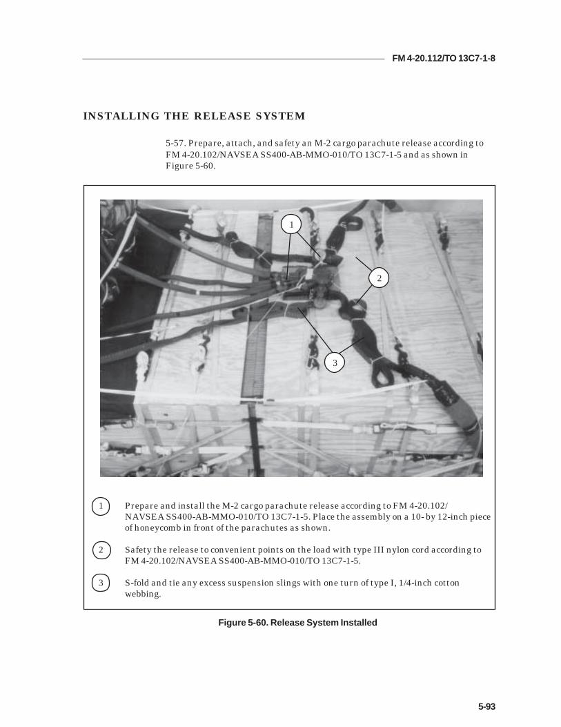
FM 4-20.112/TO 13C7-1-8
5-93
INSTALLING THE RELEASE SYSTEM
5-57. Prepare, attach, and safety an M-2 cargo parachute release according toFM 4-20.102/NAVSEA SS400-AB-MMO-010/TO 13C7-1-5 and as shown inFigure 5-60.
1 Prepare and install the M-2 cargo parachute release according to FM 4-20.102/NAVSEA SS400-AB-MMO-010/TO 13C7-1-5. Place the assembly on a 10- by 12-inch pieceof honeycomb in front of the parachutes as shown.
2 Safety the release to convenient points on the load with type III nylon cord according toFM 4-20.102/NAVSEA SS400-AB-MMO-010/TO 13C7-1-5.
3 S-fold and tie any excess suspension slings with one turn of type I, 1/4-inch cottonwebbing.
Figure 5-60. Release System Installed
2
1
3

FM 4-20.112/TO 13C7-1-8
5-94
Figure 5-61. Extraction System Installed
INSTALLING THE EXTRACTION SYSTEM
5-58. Install the extraction system according to FM 4-20.102/NAVSEA SS400-AB-MMO-010/TO 13C7-1-5 and as shown in Figure 5-61.
1 Install the components of the EFTC according to FM 4-20.102/NAVSEA SS400-AB-MMO-010/TO 13C7-1-5. Use the front mounting holes for the EFTC brackets.
2 Install a 16-foot EFTC cable according to FM 4-20.102/NAVSEA SS400-AB-MMO-010/TO 13C7-1-5 and safety the cable to tie-down ring D8 with one turn of type I, 1/4-inchcotton webbing.
3 Attach a 12-foot (2-loop), type XXVI nylon sling according to FM 4-20.102/NAVSEA SS400-AB-MMO-010/TO 13C7-1-5 to be used as a deployment line. S-fold the excess and tie it intwo places with type I, 1/4-inch cotton webbing.
D8
2
1
3

FM 4-20.112/TO 13C7-1-8
5-95
PLACING EXTRACTION PARACHUTE
5-59. Select the extraction parachute and extraction line needed using the extractionline requirements table in FM 4-20.102/ NAVSEA SS400-AB-MMO-010/TO 13C7-1-5.Place the extraction parachute and line on the load for installation in the aircraft.
INSTALLING PROVISIONS FOR EMERGENCY RESTRAINTS
5-60. Select and install the provisions for the emergency aft restraints according tothe emergency aft restraint requirements table in FM 4-20.102/NAVSEA SS400-AB-MMO-010/TO 13C7-1-5.
MARKING RIGGED LOAD
5-61. Mark the rigged load according to FM 4-20.102/NAVSEA SS400-AB-MMO-010/TO 13C7-1-5, and as shown in Figure 5-62. Complete Shipper'sDeclaration for Dangerous Goods. If the load varies from the one shown, the weight,height, CB, and parachute requirements must be recomputed.
EQUIPMENT REQUIRED
5-62. Use the equipment listed in Table 5-4 to rig this load.
Note: Table does not include materials which may be needed to pad andrestrain supplies inside the boxes.
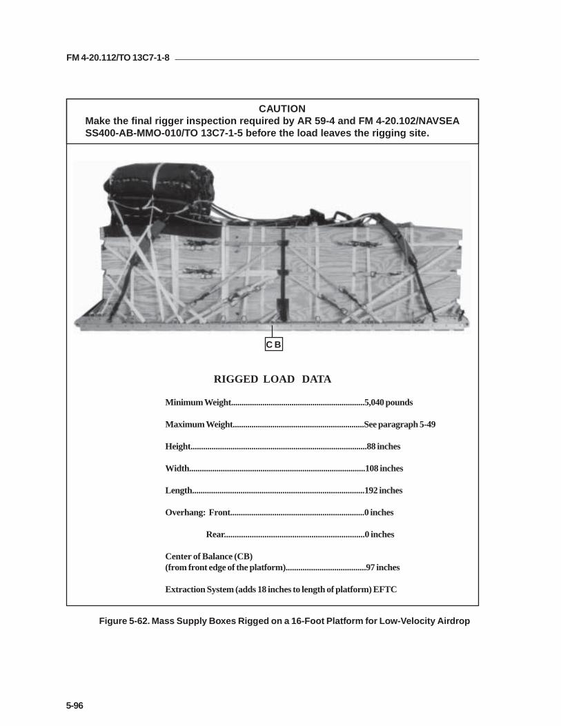
FM 4-20.112/TO 13C7-1-8
5-96
RIGGED LOAD DATA
Minimum Weight................................................................5,040 pounds
Maximum Weight...............................................................See paragraph 5-49
Height....................................................................................88 inches
Width....................................................................................108 inches
Length..................................................................................192 inches
Overhang: Front................................................................0 inches
Rear..................................................................0 inches
Center of Balance (CB)(from front edge of the platform)......................................97 inches
Extraction System (adds 18 inches to length of platform) EFTC
Figure 5-62. Mass Supply Boxes Rigged on a 16-Foot Platform for Low-Velocity Airdrop
C B
CAUTIONMake the final rigger inspection required by AR 59-4 and FM 4-20.102/NAVSEASS400-AB-MMO-010/TO 13C7-1-5 before the load leaves the rigging site.

FM 4-20.112/TO 13C7-1-8
5-97
Table 5-4. Equipment Required for Rigging Mass Supply Boxes on a 16-Foot, Type VPlatform for Low-Velocity Airdrop
National Stock Item Quantity Number
8040-00-273-8713 Adhesive paste, 1-gal. As required4030-00-090-5354 Clevis, suspension, 1-inch (large) 58305-00-880-8155 Cloth, coated (nylon, type II, 17.0 oz, green, 60-in) As required4020-00-240-2146 Cord, nylon, type III, 550-lb. As required1670-00-434-5785 Coupling, airdrop extraction force transfer, w/16-ft. cable 11670-00-360-0328 Cover, clevis 48135-00-664-6958 Cushioning material (Cellulose wadding) As required8305-00-958-3685 Felt, 1/2-inch thick As required1670-01-183-2678 Leaf, extraction line (line bag) ( add 2 for C-17) 2
Line extraction:1670-01-062-6313 60-foot (3-loop), type XXVI (for C-130) 11670-01-107-7651 140-foot (3-loop), type XXVI (for C-5) 11670-01-107-7651 140-foot (3-loop), type XXVI (for C-17) 11670-01-064-4452 60-foot (1-loop), type XXVI (for C-17), (drogue line) 1
Link assembly, two-point:5306-00-435-8994 Bolt, 1-inch diameter, 4-inches long (add 4 for C-5) 25310-00-232-5165 Nut, 1-inch (add 4 for C-5) 2
1670-00-003-1953 Plate, side, 3 3/4-inch 25365-00-007-3414 Spacer, large (add 4 for C-5) 2
5510-00-2206146 Lumber, 2- by- 4- by:45-in84 1/2-in85-in 14
5315-00-010-4657 Nail, steel wire, common, 6d As required5315-00-010-4659 Nail, steel wire, common, 8d As required1670-00-753-3928 Pad, energy-dissipating (honeycomb)
3- by 36- by 96-inches 1 sheet1670-01-016-7841 Parachute, cargo, G-11 4
Parachute, cargo, extraction:1670-00-040-8135 28-ft. 11670-01-063-3715 15-ft. (C-17 only) 1
Platform, airdrop, type V, 16-ft:1670-00-128-4981 Plywood, 3/4- by 48- by 96-in 12 sheets1670-01-162-2372 Clevis assembly (type V) (56)1670-01-353-8424 Extraction bracket assembly (1)1670-01-162-2381 Link, tandem, suspension link assembly (4)1670-01-097-8817 Release, cargo parachute, M-2 1

FM 4-20.112/TO 13C7-1-8
5-98
Table 5-4. Equipment Required for Rigging Mass Supply Boxes on a 16-Foot, Type VPlatform for Low-Velocity Airdrop (Continued)
National Stock Item Quantity Number
Sling, cargo, airdrop:1670-01-062-6308 16-ft. (4-loop), type XXVI 41670-01-062-6303 12-ft. (2-loop), type XXVI 11670-01-062-6313 60-foot (3-loop), type XXVI 4
5340-00-040-8219 Strap, parachute, release, multi-knife 27501-00-266-5016 Tape, adhesive, 2-inch As required1670-00-937-0271 Tiedown assembly, 15-ft. 861670-01-483-8259 Towplate release mechanism (H-block) (C-17 only) 1
Webbing:8305-00-268-2411 Cotton, 1/4-inch, type I As required8305-00-082-5752 Nylon, tubular, 1/2-inch As required8305-00-261-8585 Type VIII nylon As required

FM 4-20.112/TO 13C7-1-8
6-1
Chapter 6
RIGGING MASS SUPPLY BOX ON A 20-FOOT, TYPE V
PLATFORM FOR LOW-VELOCITY AIRDROP
DESCRIPTION OF LOAD
6-1. Two mass supply boxes are rigged for low-velocity airdrop on a 20-foot,type V airdrop platform. Loads may include any bulk items of general supplythat can be packed into the box without shifting the load. Each load mustweigh at least 6,300 pounds, including parachutes. Refer to FM 4-20.102/NAVSEA SS400-AB-MMO-010/TO 13C7-1-5 for the weight limitations for thenumber of parachutes to be used.
PREPARING PLATFORM
6-2. Prepare a 20-foot, type V platform as shown in Figure 6-1.

FM 4-20.112/TO 13C7-1-8
6-2
Step:
1. Inspect, or assemble and inspect, a 20-foot, type V platform as outlined in TM 10-1670-268-20&P/TO 13C7-52-22.
2. Install a suspension link in holes 6, 7, and 8 on each platform side rail. Face the flatend of the link to the front of the platform.
3. Install a suspension link in holes 33, 34, and 35 on each platform side rail. Face theflat end of the link to the rear of the platform.
4. Install a tandem link to the front of each platform side rail using holes 1, 2, and3.
5. Install clevises on bushings 1 and 2 on each front tandem link.
6. Install clevises on bushings 1 and 3 on the first suspension link on each side.
7. Install clevises on bushings 2, 3, and 4 on the second suspension link on each side.
8. Starting at the front of the right and left platform side rail, install clevises on thebushings bolted to holes 5, 10, 11, 12, 13, 14, 17, 19, 20, 21, 22, 25, 28, 29, 30, 31,37, 39, and 40.
9. Starting at the front of the platform, number the clevises 1 through 26 on the rightside, and 1A through 26A on the left side.
10. Label the tiedown rings according to FM 4-20.102/NAVSEA SS400-AB-MMO-010/TO 13C7-1-5.
Figure 6-1. Platform Prepared
CLEVISES 26 THROUGH 1
CLEVISES 26A THROUGH 1A
REAR FRONT
RIGHT
LEFT

FM 4-20.112/TO 13C7-1-8
6-3
PLACING LASHINGS ON PLATFORM
6-3. Pre-position fourteen 15-foot lashings through the tie-down rings on theplatform as shown in Figure 6-2.
Figure 6-2. Lashings Pre-positioned on Platform
1 Pass the end of a 15-foot lashing through tie-down ring A2 and through its own D-ring.Roll the free end neatly inside the rail. Repeat for tie-down rings A3, A4, A5, A7, A8, andA9.
2 Pass the end of a 15-foot lashing through tie-down ring B2 and through its own D-ring.Roll the free end neatly inside the rail. Repeat for tie-down rings B3, B4, B5, B7, B8, andB9.
2
1
A9 A8 A7 A5 A4 A3 A2
B9 B8 B7 B5 B4 B3 B2

FM 4-20.112/TO 13C7-1-8
6-4
Figure 6-3. Box Ends Constructed
CONSTRUCTING AND FORMING STORAGE BOX COMPONENTS
6-4. Construct the individual components of a storage box as shown in Figures6-3, 6-4, and 6-5. Partially assemble the first box for loading asshown in Figure 6-6.
Notes:1. This drawing is not to scale.2. All dimensions are in inches.3. Use 8d nails.
92
85
48
3 1/2
1 Cut four 3/4-by 48- by 92-inch pieces of plywood.
2 Nail a 2- by 4- by 85-inch piece of lumber along the top and bottom edges of each of thefour end pieces with 8d nails as shown. Allow the plywood to extend past the lumber 3 1/2inches on each side.
1
1
2

FM 4-20.112/TO 13C7-1-8
6-5
Notes:1. This drawing is not to scale.2. All dimensions are in inches.3. Use 8d nails.
13 1/4
14 16 16 16 1615 1/4
LUMBER2 X 4 X 45
PLYWOOD3/4 X 48 X 16PLYWOOD
3/4 X 48 X 96
LUMBER2 X 4 X 106 1/2
12
6
12
9
3
23
12
2 3/4
Figure 6-4. Box Sides Constructed
1 Build a frame of 2- by 4-inch lumber as shown for each of the four box sides required.Space the upright pieces exactly as shown. Spacing is measured on center, except theends.
2 Lay a full 3/4- by 48- by 96-inch sheet of plywood and a 3/4- by 16- by 48-inch piece ofplywood, unfinished side down, over the frame made in step 1 so that the joint betweenthe pieces is centered over the second upright from the left. Nail the plywood to the frameso that the edges are flush with the top and bottom of the frame, and the plywood extendspast the frame 2 3/4 inches on each end.
3 Make 2- by 3-inch cutouts as shown in each of the four sides. Face the 12-inch cutout tothe right on two of the sides, and to the left on the other two.
3
2
1

FM 4-20.112/TO 13C7-1-8
6-6
Figure 6-5. Tops of Boxes Constructed
Notes:1. This drawing is not to scale.2. All dimensions are in inches.3. Use 8d nails.
PLYWOOD3/4 X 48 X 93 1/2
PLYWOOD3/4 X 12 X 93 1/2
111
2
3
1 Cut two 3/4- by 48- by 93 1/2-inch pieces of plywood. In addition, cut a 3/4- by 12- by93 1/2-inch piece of plywood.
2 Lay the pieces of plywood cut in step 1 together, finished side up, as shown.
3 Space four 2- by 4- by 85-inch pieces of lumber flat side down under the plywood as shown.Nail the plywood to the lumber.
4 Repeat steps 1 through 3 to make the top for the second box. (Not shown)

FM 4-20.112/TO 13C7-1-8
6-7
RIGHT FRONT
FRONT RIGHT
2
1
Figure 6-6. Box Partially Assembled for Loading
1 Assemble the box on the platform. Fit each end of the first box between the sides with theleft and right of each end flush against the inside vertical lumber uprights on the sides.
2 Nail the pieces of the box together with 8d nails through the ends of the box into thevertical lumber pieces in the sides.
3 Be sure that the front end of the box is centered and is 9 inches from the front edge of theplatform.
1
3

FM 4-20.112/TO 13C7-1-8
6-8
Figure 6-7. Boxes Closed
LOADING AND CLOSING THE BOXES
6-5. Load and close the boxes as described below.
a. Use the tie-down rings inside the box to secure the load, if necessary.
b. Use honeycomb, if necessary, to cover the platform inside the box or tofill empty space.
c. The inside ends of both boxes may be cut out to allow for long items suchas lumber or tent poles.
d. Assemble and load the second box. Allow 6 inches between the ends of thetwo boxes.
e. Close both boxes as shown in Figure 6-7.
INSTALLING LASHINGS
6-6. Install the lashings and secure pre-positioned lashings as shown in Figures6-8 through 6-15.
Notes:
1. Pad the cutouts in the box sides with cellulose wadding. Tape thewadding in place.2. This load requires lashings over 30 feet in length. Lashings must bepositioned through clevises before sections are joined together.
1 Align the box tops with the lumber facing down.
2 Nail the tops to the boxes with 8d nails.
2
1

FM 4-20.112/TO 13C7-1-8
6-9
Figure 6-8. Pre-positioned Lashings Secured to Lashings on Platform Rails
1 Pass a 15-foot lashing through clevis 3 and through its own D-ring. Do the same forclevises 3A, 6, 6A, 9, 9A, 11, and 11A.
2 Secure the pre-positioned lashing in tie-down ring B2 to the lashing in clevis 3 on top ofthe box with two D-rings and a load binder.
3 Secure the pre-positioned lashing in tie-down ring A2 to the lashing in clevis 3A on top ofthe box with two D-rings and a load binder.
4 Secure the pre-positioned lashing in tie-down ring B3 to the lashing in clevis 6 on top ofthe box with two D-rings and a load binder.
5 Secure the pre-positioned lashing in tie-down ring A3 to the lashing in clevis 6A on top ofthe box with two D-rings and a load binder.
6 Secure the pre-positioned lashing in tie-down ring B4 to the lashing in clevis 9 on top ofthe box with two D-rings and a load binder.
7 Secure the pre-positioned lashing in tie-down ring A4 to the lashing in clevis 9A on top ofthe box with two D-rings and a load binder.
8 Secure the pre-positioned lashing in tie-down ring B5 to the lashing in clevis 11 on top ofthe box with two D-rings and a load binder.
9 Secure the pre-positioned lashing in tie-down ring A5 to the lashing in clevis 11A on top ofthe box with two D-rings and a load binder.
2
5
4
7
6
98
3
11 9 6 3

FM 4-20.112/TO 13C7-1-8
6-10
Figure 6-9. Lashings 1 Through 5 Installed
3
2
1
3
2
5
1
4
10 8 7 5 4
gnihsaLrebmuN
nwodeiTrebmuNsivelC
snoitcurtsnI
1 A4dna4 hguorhtdnasesivelchtobhguorhtgnihsaltoof-03assaPtnorfehtnignihsalehteruceS.stuotuctnorfmottobeht
.rednibdaoladnasgnir-Dowthtiw
2 A5dna5 hguorhtdnasesivelchtobhguorhtgnihsaltoof-03assaPtnorfehtnignihsalehteruceS.stuotuctnorfelddimeht
.rednibdaoladnasgnir-Dowthtiw
3 A8dna8 hguorhtdnasesivelchtobhguorhtgnihsaltoof-54assaPhtiwtnorfehtnignihsalehteruceS.stuotuctnorfpoteht
.rednibdaoladnasgnir-Dowt
4 A01dna01 hguorhtdnasesivelchtobhguorhtgnihsaltoof-54assaPeruceS.xobtsrifehtfoedisraerehtnostuotucelddimeht.rednibdaoladnasgnir-Dowthtiwedisehtnognihsaleht
5 A7dna7 hguorhtdnasesivelchtobhguorhtgnihsaltoof-54assaPehteruceS.xobtsrifehtfoedisraerehtnostuotucpoteht
.rednibdaoladnasgnir-Dowthtiwedisehtnognihsal

FM 4-20.112/TO 13C7-1-8
6-11
Figure 6-10. Lashings 6 and 7 Installed
6
7
6
1
12
1A
gnihsaLrebmuN
nwodeiTrebmuNsivelC
snoitcurtsnI
6 21dna1 potehthguorht,1sivelchguorhtgnihsaltoof-06assaPtfelehtdnuoradnaxobtsrifehtfoedistfelehtnituotuc
tfelpotehthguorhtgnihsalehtssaP.xobehtfoedissivelchguorhtdnaxobtsrifehtfoedisraerehtnotuotuc
sgnir-DowthtiwedistfelehtnognihsalehteruceS.21.rednibdaoladna
7 A21dnaA1 potehthguorht,A1sivelchguorhtgnihsaltoof-06assaPthgirehtdnuoradnaxobtsrifehtfoedisthgirehtnituotuc
thgirpotehthguorhtgnihsalehtssaP.xobehtfoedissivelchguorhtdnaxobtsrifehtfodneraerehtnotuotuc
sgnir-DowthtiwedisthgirehtnognihsalehteruceS.A21.rednibdaoladna

FM 4-20.112/TO 13C7-1-8
6-12
Figure 6-11. Lashings 8 and 9 Installed
89 8
13
2
2A
gnihsaLrebmuN
nwodeiTrebmuNsivelC
snoitcurtsnI
8 31dna2 ehthguorht,2sivelchguorhtgnihsaltoof-06assaPdna,xobtsrifehtfoedistfelehtnituotuctfelelddim
hguorhtgnihsalehtssaP.xobehtfoedistfelehtdnuoradnaxobtsrifehtfodneraerehtnotuotuctfelelddimehthtiwedistfelehtnognihsalehteruceS.31sivelchguorht
.rednibdaoladnasgnir-Dowt
9 A31dnaA2 ehthguorht,A2sivelchguorhtgnihsaltoof-06assaPdnaxobtsrifehtfoedisthgirehtnituotucthgirelddim
hguorhtgnihsalehtssaP.xobehtfoedisthgirehtdnuoradnaxobtsrifehtfodneraerehtnotuotucthgirelddimeht
edisthgirehtnognihsalehteruceS.A31sivelchguorht.rednibdaoladnasgnir-Dowthtiw

FM 4-20.112/TO 13C7-1-8
6-13
Figure 6-12. Pre-positioned Lashings Secured to Lashings on Platform Rails
1 Pass a 15-foot lashing through clevis 16 and through its own D-ring. Do the same forclevises 16A, 18, 18A, 21, 21A, 24, and 24A.
2 Secure the pre-positioned lashing in tie-down ring B7 to the lashing in clevis 16 on top ofthe box with two D-rings and a load binder.
3 Secure the pre-positioned lashing in tie-down ring A7 to the lashing in clevis 16A on top ofthe box with two D-rings and a load binder.
4 Secure the pre-positioned lashing in tie-down ring B8 to the lashing in clevis 18 on top ofthe box with two D-rings and a load binder.
5 Secure the pre-positioned lashing in tie-down ring A8 to the lashing in clevis 18A on top ofthe box with two D-rings and a load binder.
6 Secure the pre-positioned lashing in tie-down ring B9 to the lashing in clevis 21 on top ofthe box with two D-rings and a load binder.
7 Secure the pre-positioned lashing in tie-down ring A9 to the lashing in clevis 21A on top ofthe box with two D-rings and a load binder.
8 Secure the lashings in clevises 24 and 24A together on top of the box with two D-rings anda load binder.
8
6 7
5
4
32
24 21 18 16

FM 4-20.112/TO 13C7-1-8
6-14
Figure 6-13. Lashings 10 Through 14 Installed
13
12
11
14
10
23 22 20 19 17
gnihsaLrebmuN
nwodeiTrebmuNsivelC
snoitcurtsnI
01 A71dna71 hguorhtdnasesivelchtobhguorhtgnihsaltoof-03assaP.xobdnocesehtfodnetnorfehtnistuotucelddimeht
daoladnasgnir-DowthtiwedisehtnognihsalehteruceS.rednib
11 A91dna91 hguorhtdnasesivelchtobhguorhtgnihsaltoof-54assaPeruceS.xobdnocesehtfodnetnorfehtnistuotucpoteht
.rednibdaoladnasgnir-Dowthtiwedisehtnognihsaleht
21 A02dna02 hguorhtdnasesivelchtobhguorhtgnihsaltoof-54assaPhtiwraerehtnignihsalehteruceS.stuotucraerpoteht
.rednibdaoladnasgnir-Dowt
31 A22dna22 hguorhtdnasesivelchtobhguorhtgnihsaltoof-03assaPhtiwraerehtnignihsalehteruceS.stuotucraerelddimeht
.rednibdaoladnasgnir-Dowt
41 A32dna32 hguorhtdnasesivelchtobhguorhtgnihsaltoof-03assaPraerehtnignihsalehteruceS.stuotucraermottobeht
.rednibdaoladnasgnir-Dowthtiw

FM 4-20.112/TO 13C7-1-8
6-15
Figure 6-14. Lashings 15 and 16 Installed
1516
1514
25
25 A
gnihsaLrebmuN
nwodeiTrebmuNsivelC
snoitcurtsnI
51 52dna41 ehthguorht,41sivelchguorhtgnihsaltoof-06assaPdnaxobdnocesehtfoedistfelehtnituotucelddim
hguorhtgnihsalehtssaP.xobehtfoedistfelehtdnuora.52sivelchguorhtdnaraerehttatuotucelddimtfeleht
daoladnasgnir-DowthtiwraerehtnignihsalehteruceS.rednib
61 A52dnaA41 ehthguorht,A41sivelchguorhtgnihsaltoof-06assaPdnaxobdnocesehtfoedisthgirehtnituotucelddim
hguorhtgnihsalehtssaP.xobehtfoedisthgirehtdnuora.A52sivelchguorhtdnaraerehttatuotucelddimthgireht
dnasgnir-DowthtiwedisthgirehtnognihsalehteruceS.rednibdaola

FM 4-20.112/TO 13C7-1-8
6-16
Figure 6-15. Lashings 17 and 18 Installed
17
18
17
26
15
26 A
gnihsaLrebmuN
nwodeiTrebmuNsivelC
snoitcurtsnI
71 62dna51 potehthguorht,51sivelchguorhtgnihsaltoof-06assaPehtdnuoradnaxobdnocesehtfoedistfelehtnistuotuc
pottfelehthguorhtgnihsalehtssaP.xobehtfoedistfelehteruceS.62sivelchguorhtdnaraerehttatuotuc
.rednibdaoladnasgnir-Dowthtiwraerehtnignihsal
81 A62dnaA51 potehthguorht,A51sivelchguorhtgnihsaltoof-06assaPehtdnuoradnaxobdnocesehtfoedisthgirehtnistuotucpotthgirehthguorhtgnihsalehtssaP.xobehtfoedisthgir
ehteruceS.A62sivelchguorhtdnaraerehttatuotucdaoladnasgnir-Dowthtiwedisthgirehtnognihsal
.rednib

FM 4-20.112/TO 13C7-1-8
6-17
INSTALLING LOAD COVER, SUSPENSION SLINGS AND DEADMAN’STIE
6-7. Install the load cover, honeycomb buffers, suspension slings and deadman’stie as shown in Figure 6-16.
1 Slide two 6- by 92-inch pieces of honeycomb between the two boxes at the top. The honey-comb may be held in place by lengths of type III nylon cord tied around the honeycombto convenient locations.
2 Cover the rear fourth of the load with a 60- by 96-inch piece of cloth coated nylon. Securethe cover to the adjacent lashings with type III nylon cord.
3 Pass one end of a 20-foot (4-loop), type XXVI nylon suspension sling through the bellportion of a large suspension clevis. Bolt the clevis to the suspension hole of the rightfront suspension link.
4 Install on the left front suspension link and the right rear and left rear suspension links a20-foot (4-loop), type XXVI nylon suspension slings as in step 3.
5 Raise the slings and install the deadman's tie according to FM 4-20.102/NAVSEA SS400-AB-MMO-010/TO 13C7-1-5.
6 Pad the suspension slings with felt tied and tape in place 36 inches above the suspensionclevises to 8 inches above the top of the load. Extend the tape 6 inches beyond the top andbottom of the felt.
7 Tie the front suspension slings together over the top of the load with a single length oftype III nylon cord. Tie the rear suspension slings the same way.
Figure 6-16. Load Cover, Suspension Slings, and Deadman’s Tie Installed
1
2
3
4
56
6
77

FM 4-20.112/TO 13C7-1-8
6-18
INSTALLING PARACHUTES
6-8. Compute the parachute requirements for the load being rigged. Prepareand install the cargo parachutes according to FM 4-20.102/ NAVSEA SS400-AB-MMO-010/TO 13C7-1-5 and as shown in Figure 6-17.
1 Prepare, position, and stow four G-11 cargo parachutes on the rear of the load accordingto FM 4-20.102/ NAVSEA SS400-AB-MMO-010/TO 13C7-1-5.
2 Install the front cargo parachute restraints according to FM 4-20.102/ NAVSEA SS400-AB-MMO-010/TO 13C7-1-5 using type VIII nylon webbing to clevises 25 and 25A.
3 Install the center cargo parachute restraints according to FM 4-20.102/ NAVSEA SS400-AB-MMO-010/TO 13C7-1-5 using type VIII nylon webbing to clevises 23 and 23A.
4 Install the rear cargo parachute restraints according to FM 4-20.102/ NAVSEA SS400-AB-MMO-010/TO 13C7-1-5 using type VIII nylon webbing to clevises 21 and 21A.
5 Install the parachute release straps according to FM 4-20.102/ NAVSEA SS400-AB-MMO-010/TO 13C7-1-5.
Figure 6-17. Cargo Parachutes Installed
1
5
4
3
2
25 2123

FM 4-20.112/TO 13C7-1-8
6-19
INSTALLING THE RELEASE SYSTEM
6-9. Prepare, attach, and safety an M-2 cargo parachute release according toFM 4-20.102/NAVSEA SS400-AB-MMO-010/TO 13C7-1-5 and as shown inFigure 6-18.
1 Prepare and install the M-2 cargo parachute release according to FM 4-20.102/NAVSEA SS400-AB-MMO-010/TO 13C7-1-5. Place the assembly in front of the parachutesas shown.
2 Safety the release to convenient points on the load with type III nylon cord according toFM 4-20.102/NAVSEA SS400-AB-MMO-010/TO 13C7-1-5.
3 S-fold and tie any excess suspension slings with one turn of type I, 1/4-inch cottonwebbing.
Figure 6-18. Release System Installed
1
3
2

FM 4-20.112/TO 13C7-1-8
6-20
Figure 6-19. Extraction System Installed
INSTALLING THE EXTRACTION SYSTEM
6-10. Install the extraction system according to FM 4-20.102/NAVSEA SS400-AB-MMO-010/TO 13C7-1-5 and as shown in Figure 6-19.
1 Install the components of the EFTC according to FM 4-20.102/NAVSEA SS400-AB-MMO-010/TO 13C7-1-5. Use the front mounting holes for the EFTC brackets.
2 Install a 20-foot EFTC cable according to FM 4-20.102/NAVSEA SS400-AB-MMO-010/TO 13C7-1-5 and safety the cable to tie-down ring D10 with one turn of type I, 1/4-inch cotton webbing.
3 Attach a 9-foot (2-loop), type XXVI nylon sling according to FM 4-20.102/NAVSEA SS400-AB-MMO-010/TO 13C7-1-5 to be used as a deployment line. S-fold the excess and tie it intwo places with type I, 1/4-inch cotton webbing.
3
2
1
D10

FM 4-20.112/TO 13C7-1-8
6-21
PLACING EXTRACTION PARACHUTE
6-11. Select the extraction parachute and extraction line needed using the extractionline requirements table in FM 4-20.102/ NAVSEA SS400-AB-MMO-010/TO 13C7-1-5.Place the extraction parachute and line on the load for installation in the aircraft.
INSTALLING PROVISIONS FOR EMERGENCY RESTRAINTS
6-12. Select and install the provisions for the emergency aft restraints according tothe emergency aft restraint requirements table in FM 4-20.102/NAVSEA SS400-AB-MMO-010/TO 13C7-1-5.
MARKING RIGGED LOAD
6-13. Mark the rigged load according to FM 4-20.102/NAVSEA SS400-AB-MMO-010/TO 13C7-1-5, and as shown in Figure 6-20. Complete Shipper'sDeclaration for Dangerous Goods. If the load varies from the one shown, the weight,height, CB, and parachute requirements must be recomputed.
EQUIPMENT REQUIRED
6-14. Use the equipment listed in Table 6-1 to rig this load.

FM 4-20.112/TO 13C7-1-8
6-22
RIGGED LOAD DATA
Minimum Weight................................................................6,300 pounds
Maximum Weight...............................................................See paragraph 6-1
Height....................................................................................88 inches
Width....................................................................................108 inches
Length..................................................................................240 inches
Overhang: Front................................................................0 inches
Rear..................................................................0 inches
Center of Balance (CB)(from front edge of the platform)......................................126 inches
Extraction System (adds 18 inches to length of platform) EFTC
Figure 6-20. Mass Supply Boxes Rigged on a 20-Foot Platform for Low-Velocity Airdrop
C BCB
CAUTIONMake the final rigger inspection required by AR 59-4 and FM 4-20.102/NAVSEASS400-AB-MMO-010/TO 13C7-1-5 before the load leaves the rigging site.

FM 4-20.112/TO 13C7-1-8
6-23
Table 6-1. Equipment Required for Rigging Mass Supply Boxes on a 20-Foot, Type VPlatform for Low-Velocity Airdrop
National Stock Item Quantity Number
8040-00-273-8713 Adhesive paste, 1-gal. As required4030-00-090-5354 Clevis, suspension, 1-inch (large) 58305-00-880-8155 Cloth, coated (nylon, type II, 17.0 oz, green, 60-in) As required4020-00-240-2146 Cord, nylon, type III, 550-lb. As required1670-00-434-5787 Coupling, airdrop extraction force transfer, w/20-ft. cable 11670-00-360-0328 Cover, clevis 48135-00-664-6958 Cushioning material (Cellulose padding) As required8305-00-958-3685 Felt, 1/2-inch thick As required1670-01-183-2678 Leaf, extraction line (line bag) ( add 2 for C-17) 2
Line extraction:1670-01-062-6313 60-foot (3-loop), type XXVI (for C-130) 11670-01-107-7651 140-foot (3-loop), type XXVI (for C-5) 11670-01-107-7651 140-foot (3-loop), type XXVI 21670-01-107-7651 140-foot (3-loop), type XXVI (for C-17) 11670-01-064-4452 60-foot (1-loop), type XXVI (for C-17), (drogue line) 1
Link assembly, two-point:5306-00-435-8994 Bolt, 1-inch diameter, 4-inches long (add 4 for C-5) 25310-00-232-5165 Nut, 1-inch (add 4 for C-5) 21670-00-003-1953 Plate, side, 3 3/4-inch 25365-00-007-3414 Spacer, large (add 4 for C-5) 25510-00-220-6146 Lumber, 2- by 4-in
45-in85-in106 1/2
5310-00-010-4657 Nail, steel wire, common, 6d As required5315-00-010-4659 Nail, steel wire, common, 8d As required1670-00-753-3928 Pad, energy-dissipating (honeycomb)
3- by 36- by 96-inches 2 sheets1670-01-016-7841 Parachute, cargo, G-11 4
Parachute, cargo, extraction:1670-00-040-8135 28-ft. 11670-01-063-3715 15-ft. (C-17 only) 1
Platform, airdrop, type V, 16-ft:1670-01-162-2372 Clevis assembly (type V) (52)1670-01-353-8424 Extraction bracket assembly (1)1670-01-247-2389 Link, suspension bracket, type V (2)1670-01-162-2381 Link, tandem, suspension link assembly (4)1670-01-097-8817 Release, cargo parachute, M-2 1
Sling, cargo, airdrop:1670-01-062-6304 9-ft. (2-loop), type XXVI 11670-01-064-4453 20-ft. (4-loop), type XXVI 41670-01-062-6313 60-foot (3-loop), type XXVI 4

FM 4-20.112/TO 13C7-1-8
6-24
Table 6-1. Equipment Required for Rigging Mass Supply Boxes on a 20-Foot, Type VPlatform for Low-Velocity Airdrop (Continued)
National Stock Item Quantity Number
5340-00-040-8219 Strap, parachute, release, multi-knife 27501-00-266-5016 Tape, adhesive, 2-inch As required1670-00-937-0271 Tiedown assembly, 15-ft. 931670-01-483-8259 Towplate release mechanism (H-block) (C-17 only) 1
Webbing:8305-00-268-2411 Cotton, 1/4-inch, type I As required8305-00-082-5752 Nylon, tubular, 1/2-inch As required8305-00-261-8585 Type VIII nylon As required

FM 4-20.112/TO 13C7-1-8
7-1
Chapter 7
RIGGING PALLETIZED LOAD SYSTEM (PLS) ON A 24-FOOT, TYPE V PLATFORM FOR LOW-VELOCITY AIRDROP
Section I
RIGGING 105-MILLIMETER (MM) AMMUNITION
DESCRIPTION OF LOAD
7-1. The Palletized Load System (PLS) can be moved from the drop zoneand transported on a specially designed truck. Bulk supplies are lashed tothe pallet, giving the load integrity for transport. The pallet has swivelrings along the sides for lashing the load. The pallet and load are lashed tothe airdrop platform for low-velocity airdrop. The load shown consists of245 boxes of 105-millimeter ammunition. Adapt these procedures to rigother items of bulk supplies. Ammunition listed in FM 4-20.153/MCRP 4-11.3B/TO 13C7-18-41, as certified for low-velocity airdrop, may be riggedusing these procedures. The rigged load may not be more than 100 incheshigh. Refer to FM 4-20.102/NAVSEA SS400-AB-MMO-010/TO 13C7-1-5 forthe weight limitations and for the number of parachutes to be used.
PREPARING PLATFORM
7-2. Prepare a 24-foot, type V platform as shown in Figure 7-1.

FM 4-20.112/TO 13C7-1-8
7-2
Step:
1. Inspect, or assemble and inspect, a 24-foot, type V platform as outlined in TM 10-1670-268-20&P/TO 13C7-52-22.
2. Install a suspension link in holes 18, 19, and 20 on each side of the platform.
3. Install a suspension link in holes 6, 7, and 8 on each side of the platform.
4. Install a tandem link on the front of each platform side rail using holes 1, 2, and 3.
5. Install a suspension link in holes 29, 30, and 31 on each side rail.
6. Install a suspension link in holes 41, 42, and 43 on each side of the platform.
7. Install clevises on bushings 3 and 4 of each front tandem link.
8. Install a double clevis on bushing 1 of each first suspension link.
9. Install a clevis on bushing 3 of each first suspension link.
10. Install clevises on bushings 1 and 2 of each second suspension link.
11. Starting at the front of the right and left platform side rail, install clevises on thebushings bolted to holes 13, 14, 16, 23, 26, 27, 32, 38, 46, and 48.
12. Install a double clevis on bushings 4, 5, 9, 17, 35, and 37 on each side of theplatform.
13. Starting at the front of the platform, number the clevises 1 through 24 on the rightside, and 1A through 24A on the left side.
Figure 7-1. Platform Prepared
CLEVISES 24 THROUGH 1
CLEVISES 24A THROUGH 1A
REAR FRONT
RIGHT
LEFT

FM 4-20.112/TO 13C7-1-8
7-3
PREPARING AND POSITIONING HONEYCOMB7-3. Prepare ten honeycomb stacks as shown in Figures 7-2 through 7-4.Position the stacks on the platform as shown in Figure 7-5.
Figure 7-2. Stacks 1, 2, 5, and 6 Prepared
kcatSrebmuN seceiP
htdiW)sehcnI(
htgneL)sehcnI( lairetaM snoitcurtsnI
,2,16dna,5
11
4242
6767
bmocyenoHhcni-4/3doowylp
otbmocyenohrevohsulfdoowylpeulG.esabmrof
3 81 67 bmocyenoH .esabnoeulgdnaretneC
2 81 67 hcni-4/3doowylp
.bmocyenohrevohsulfeulG
7 81 2/13* hcni-4yb-2rebmul
fodnehcaerevohsulfeceipenoliaNeceipdrihtaretneC.doowylpeht
seceipowtecapS.sdneehtneewtebehtdnaeceipdnehcaeneewtebylneve
.eceipretnec1 21 67 hcni-4/3
doowylp.rebmulrevoliandnaretneC
1 6 67 hcni-4/3doowylp
.doowylprevoliandnaretneC
* Two- by four-inch lumber is actually 3 1/2 inches wide.
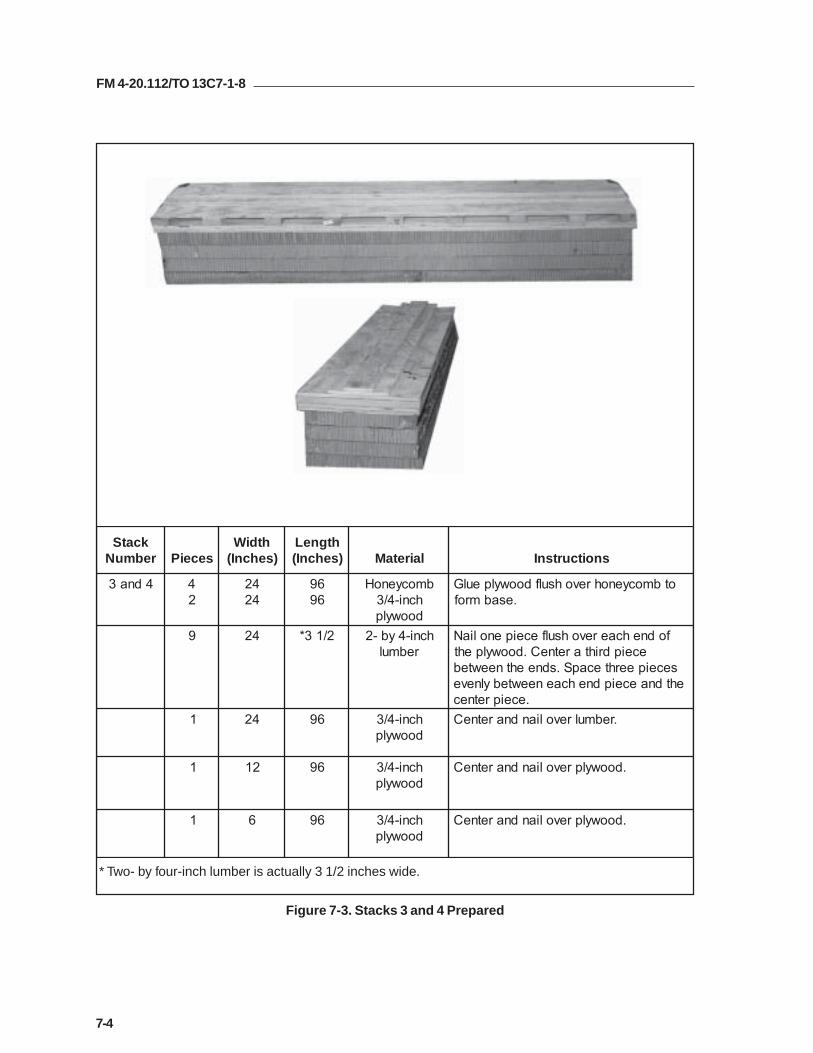
FM 4-20.112/TO 13C7-1-8
7-4
Figure 7-3. Stacks 3 and 4 Prepared
kcatSrebmuN seceiP
htdiW)sehcnI(
htgneL)sehcnI( lairetaM snoitcurtsnI
4dna3 42
4242
6969
bmocyenoHhcni-4/3doowylp
otbmocyenohrevohsulfdoowylpeulG.esabmrof
9 42 2/13* hcni-4yb-2rebmul
fodnehcaerevohsulfeceipenoliaNeceipdrihtaretneC.doowylpeht
seceipeerhtecapS.sdneehtneewtebehtdnaeceipdnehcaeneewtebylneve
.eceipretnec1 42 69 hcni-4/3
doowylp.rebmulrevoliandnaretneC
1 21 69 hcni-4/3doowylp
.doowylprevoliandnaretneC
1 6 69 hcni-4/3doowylp
.doowylprevoliandnaretneC
* Two- by four-inch lumber is actually 3 1/2 inches wide.

FM 4-20.112/TO 13C7-1-8
7-5
Figure 7-4. Stacks 7, 8, 9, and 10 Prepared
kcatSrebmuN seceiP
htdiW)sehcnI(
htgneL)sehcnI( lairetaM snoitcurtsnI
,9,8,701dna
4 61 48 bmocyenoH .esabmrofothsulfeulG
2 9 48 bmocyenoH .esabfoedisenonohsulfeulG
1 9 48 hcni-4/3doowylp
.bmocyenohrevohsulfeulG
1 9 48 bmocyenoH .doowylprevohsulfeulG
1 2/13* 48 hcni-4yb-2rebmul
.bmocyenohnoeulgdnaretneC
* Two- by four-inch lumber is actually 3 1/2 inches wide.

FM 4-20.112/TO 13C7-1-8
7-6
Figure 7-5. Honeycomb Stacks Positioned on Platform
Notes:1. This drawing is not to scale.2. All dimensions are in inches.
kcatSrebmuN mroftalPehtnokcatSfonoitisoP
1 edisnithgirehtmorfsehcni42dnamroftalpehtfoegdetnorfehthtiwhsulfecalP.egdemroftalp
2 edisnitfelehtmorfsehcni42dnamroftalpehtfoegdetnorfehthtiwhsulfecalP.egdemroftalp
3 .1kcatsdnihebdengiladnatsniagaecalP
4 .2kcatsdnihebdengiladnatsniagaecalP
5 .3kcatsdnihebdengiladnatsniagaecalP
6 .4kcatsdnihebdengiladnatsniagaecalP
7 fosedisthgirehthtiwhsulfdnamroftalpehtfoegdetnorfehtmorfsehcni23ecalP.3dna1skcats
8 fosedistfelehthtiwhsulfdnamroftalpehtfoegdetnorfehtmorfsehcni23ecalP.4dna2skcats
9 dna3skcatsfosedisthgirehthtiwhsulfdna7kcatsforaerehtotsehcni22ecalP.5
01 .6dna4skcatsfosedistfelehthtiwhsulfdna8kcatsforaerehtotsehcni22ecalP
10
22 32
24
6 4
8
2
5 3 1
9 7

FM 4-20.112/TO 13C7-1-8
7-7
Figure 7-6. Pallet Prepared
PREPARING PLS PALLET
7-4. Prepare the pallet as shown in Figure 7-6.
1 Tie the storage compartments on each side shut with type III nylon cord.
2 Pad the top of each box area with a 7- by 30-inch piece of felt, a 7- by 30-inch piece ofhoneycomb, and two 7- by 30-inch pieces of felt. Tie the padding in place with lengths oftype III nylon cord.
3 Remove the wheels and secure them in place with the pins provided. Tie the wheels to theirbrackets with a length of 1/2-inch tubular nylon webbing.
4 Pad the fixtures on the outsides of the boxes with cellulose wadding and tape.
1
3
2
4
3

FM 4-20.112/TO 13C7-1-8
7-8
Figure 7-6. Pallet Prepared (Continued)
5 Pad the second stake bracket on each side with cellulose wadding and tape.
6 Pad all four corners of the pallet around the bottom holes with cellulose wadding and tape asshown.
7 Add a platform clevis to each of the large tie-down brackets at the rear of the PLS pallet.
8 Add two platform clevises to the seventh swivel ring bracket on each side of the PLS pallet.
6 7
8
5

FM 4-20.112/TO 13C7-1-8
7-9
Figure 7-7. Pallet Positioned and Restraint Lashing Installed
POSITIONING PLS PALLET ON PLATFORM
7-5. Position the pallet on the platform and install the restraint lashings aroundthe honeycomb stacks as shown in Figure 7-7.
1 Center the pallet on the stacks with the yoke assembly to the rear. The rear edge of thepallet must be even with the rear edges of stacks 5 and 6. Be sure that the center runners ofthe pallet rest squarely on stacks 1, 2, 3, 4, 5, and 6. Be sure that the pallet side rails reston the lumber portion of stacks 7, 8, 9, and 10.
2 Pass a 15-foot lashing through clevis 5 and through its own D-ring. Pass the lashingthrough the first holes in stacks 1 and 2. Secure the lashing to clevis 5A with a load binder.
3 Pass a 15-foot lashing through clevis 19 and through its own D-ring. Pass the lashingthrough the rear holes in stacks 5 and 6. Secure the lashing to clevis 19A with a loadbinder.
5
19
1
2
3

FM 4-20.112/TO 13C7-1-8
7-10
Figure 7-8. Pallet Lashed to Platform
gnihsaLrebmuN
nwodeiTrebmuNsivelC
snoitcurtsnI
1
2
3
4
5
6
7
8
1
A1
2
A2
3
A3
6
A6
:gnihsalssaP.tniopnwod-eitedistuotnorfthgirehthguorhT
.tniopnwod-eitedistuotnorftfelehthguorhT
.tekcarbekatsdnocesehthguorhT
tekcarbekatsdnocesehthguorhT
.tniopnwod-eitedisnitnorfthgirehthguorhT
.tniopnwod-eitedisnitnorftfelehthguorhT
.gnirleviwstsrifehthguorhT
.gnirleviwstsrifehthguorhT
6
3
21
35
17
LASHING PLS PALLET TO PLATFORM
7-6. Lash the PLS pallet to the platform as shown in Figure 7-8.

FM 4-20.112/TO 13C7-1-8
7-11
Figure 7-8. Pallet Lashed to Platform (Continued)
gnihsaLrebmuN
nwodeiTrebmuNsivelC
snoitcurtsnI
9
01
11
21
31
41
51
61
9
A9
21
A21
31
A31
41
A41
:gnihsalssaP.gnirleviwsdrihtehthguorhT
.gnirleviwsdrihtehthguorhT
.gnirleviwshtruofehthguorhT
.gnirleviwshtruofehthguorhT
.diksehtniselohraerehthguorhT
.diksehtniselohraerehthguorhT
.diksehtniselohtnorfehthguorhT
.diksehtniselohtnorfehthguorhT
13
15 911
14 91213

FM 4-20.112/TO 13C7-1-8
7-12
Figure 7-8. Pallet Lashed to Platform (Continued)
gnihsaLrebmuN
nwodeiTrebmuNsivelC
snoitcurtsnI
71
81
91
02
12
22
81
A81
02
A02
22
A22
:gnihsalssaP.gnirleviwshtneveleehthguorhT
.gnirleviwshtneveleehthguorhT
.gnirnwod-eitrenrocthgirehthguorhT
.gnirnwod-eitrenroctfelehthguorhT
.tniopnwod-eitedistuothgirehthguorhT
.tniopnwod-eitedistuotfelehthguorhT
22
2119
17
22
2018
22A

FM 4-20.112/TO 13C7-1-8
7-13
1 Cover the pallet with five 96- by 36-inch pieces of honeycomb, beginning 4 1/2 inches fromthe front edge.
2 Place and center five 30-foot lashings across the honeycomb at 18 inches, 54 inches, 90inches, 124 inches, and 160 inches from the front of the honeycomb.
3 Center the D-rings of three 30-foot lashings on the second of the lashings placed in step 2.Center one of the lashings, and place the other two 7 inches from each side.
4 Center the D-rings of three 30-foot lashings between the fourth and fifth lashingsplaced in step 2. Center one of the lashings, and place the other two 7 inches from eachside.
Figure 7-9. Honeycomb and Lashings Placed on the Pallet
PLACING AND LASHING THE LOAD
7-7. Place a layer of honeycomb and eleven 30-foot lashings on the pallet asshown in Figure 7-9. Place 245 boxes of 105-millimeter ammunition on thepallet and bind the boxes together with the lashings as shown in Figure 7-10.Construct four endboards as shown in Figure 7-11. Secure the boxes andendboards to the front section of the pallet as shown in Figure 7-12. Secure theboxes and endboards to the rear section of the pallet as shown in Figure 7-13.Lash the load to the platform as shown in Figure 7-14.
1
3
2
4
FRONT

FM 4-20.112/TO 13C7-1-8
7-14
Figure 7-10. Ammunition Boxes Placed on Pallet
1 Place boxes (three rows of seven each) flush with the front edge of the honeycomb. Placetwo more stacks of 21 each flush behind these.
2 Cover the three layers of boxes with a layer of honeycomb.
3 Place four layers of boxes over the boxes and honeycomb placed in steps 1 and 2 above.
4 Fasten the three side-to-side lashings on top of the boxes.
5 Bring the center lashings on top of the boxes.
4
1
3
5
2

FM 4-20.112/TO 13C7-1-8
7-15
Figure 7-10. Ammunition Boxes Placed on Pallet (Continued)
6 Cut out the honeycomb between the two stacks of boxes to allow the endboards to rest onthe pallet.
7 Beginning 16 inches from the front stack of boxes, place 98 boxes on the honeycomb in thesame configuration as in steps 1 through 3.
8 Secure the two side-to-side lashings on top of the boxes.
9 Route and secure the three front-to-rear lashings in the same way as in step 5. (Notshown)
8
7 6
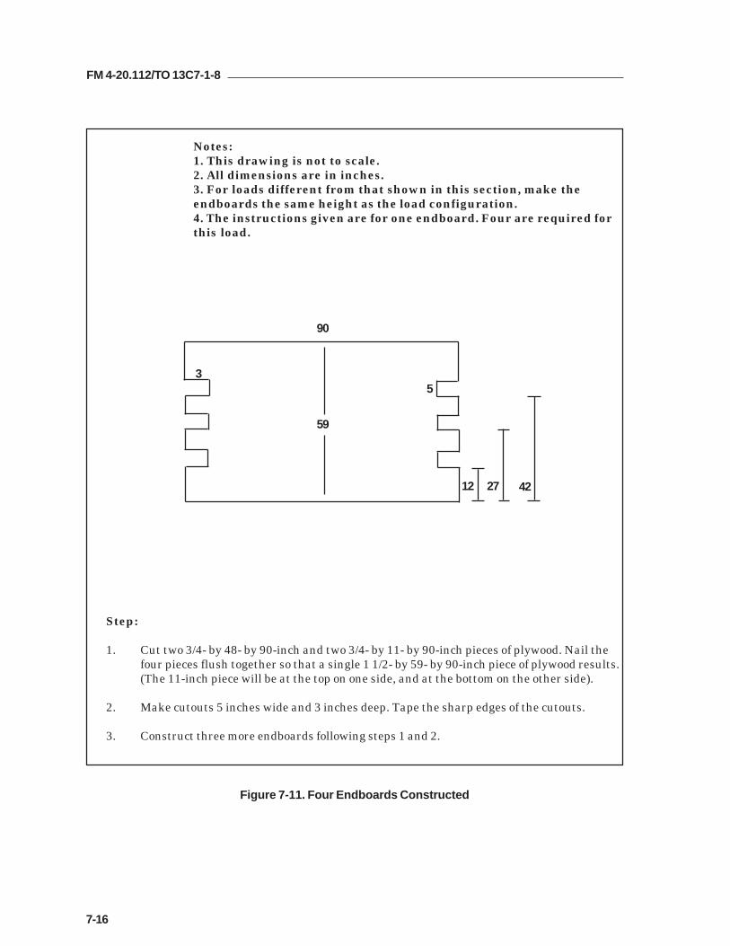
FM 4-20.112/TO 13C7-1-8
7-16
3
90
59
12 27 42
Notes:1. This drawing is not to scale.2. All dimensions are in inches.3. For loads different from that shown in this section, make theendboards the same height as the load configuration.4. The instructions given are for one endboard. Four are required forthis load.
5
Step:
1. Cut two 3/4- by 48- by 90-inch and two 3/4- by 11- by 90-inch pieces of plywood. Nail thefour pieces flush together so that a single 1 1/2- by 59- by 90-inch piece of plywood results.(The 11-inch piece will be at the top on one side, and at the bottom on the other side).
2. Make cutouts 5 inches wide and 3 inches deep. Tape the sharp edges of the cutouts.
3. Construct three more endboards following steps 1 and 2.
Figure 7-11. Four Endboards Constructed

FM 4-20.112/TO 13C7-1-8
7-17
Figure 7-12. Front Boxes and Endboards Secured to Pallet
1 Set an endboard against each end of the front stack of boxes. Center a 30-foot lashing onthe front endboard and pass the free ends through the middle cutouts. Secure the ends tothe fifth swivel ring with D-rings and load binders.
2 Center a 30-foot lashing on the second endboard and pass the free ends through the middlecutouts. Secure the ends to the fifth swivel ring with D-rings and a load binder.
3 Place a 15-foot lashing in the lower cutouts of the first endboard. Secure each end of thelashing to the second swivel ring with a load binder.
4 Center a 30-foot lashing on the second endboard and pass the free ends through the uppercutouts. Secure the ends to the second swivel ring with D-rings and a load binder.
5 Place a 15-foot lashing in the lower cutouts of the second endboard. Secure each end of thelashing to the sixth swivel ring with a load binder.
6 Center a 30-foot lashing on the first endboard and pass the free ends through the uppercutouts. Secure the ends to the sixth swivel ring with D-rings and a load binder.
7 Center a 30-foot lashing against the right side and pass the free ends through the uppercutouts in the right side of both endboards. Secure the ends to the left front clevis in thefront tie-down point and to the seventh swivel ring on the left side with D-rings and loadbinders. Fasten the load binder to the platform clevis installed earlier.
8 Center a 30-foot lashing against the left side and pass the free ends through the uppercutouts in the left side of both endboards. Secure the ends to the right front clevis in thefront tie-down point and to the seventh swivel ring on the right side with D-rings and loadbinders. Fasten the load binder to the platform clevis installed earlier.
6
1
3
7
42
58
8

FM 4-20.112/TO 13C7-1-8
7-18
Figure 7-13. Rear Boxes and Endboards Secured to Pallet
1 Set an endboard against each end of the rear stack of boxes. Center a 30-foot lashing onthe third endboard and pass the free ends through the middle cutouts. Secure the ends tothe ninth swivel ring with D-rings and load binders.
2 Center a 30-foot lashing on the fourth endboard and pass the free ends through the middlecutouts. Secure the ends to the ninth swivel ring with D-rings and a load binders.
3 Place a 15-foot lashing in the lower cutouts of the third endboard. Secure each end of thelashing to the second swivel ring with a load binder.
4 Center a 30-foot lashing on the fourth endboard and pass the free ends through the uppercutouts. Secure the ends to the eighth swivel ring with D-rings and a load binder.
5 Place a 15-foot lashing in the lower cutouts of the fourth endboard. Secure each end of thelashing to the tenth swivel ring with a load binder.
6 Center a 30-foot lashing on the third endboard and pass the free ends through the uppercutouts. Secure the ends to the tenth swivel ring with D-rings and a load binder.
7 Center a 30-foot lashing against the right side and pass the free ends through the uppercutouts in the right side of both endboards. Secure the ends to the clevis on the eleventhswivel ring and to the seventh swivel ring on the left side with D-rings and loadbinders. Fasten the load binder to the remaining platform clevis installed earlier.
8 Center a 30-foot lashing against the left side and pass the free ends through the uppercutouts in the left side of both endboards. Secure the ends to the clevis on the eleventhswivel ring and to the seventh swivel ring on the right side with D-rings and loadbinders. Fasten the load binder to the remaining platform clevis installed earlier.
7
6
1
3
2
4
5
8
8

FM 4-20.112/TO 13C7-1-8
7-19
Figure 7-14. Load Lashed to Platform
gnihsaLrebmuN
nwodeiTrebmuNsivelC
snoitcurtsnI
1
2
3
4
5
A4dna4
A7dna7
A8dna8
A01dna01
A11dna11
:gnihsaltoof-03ssaPoterucesdna,dneeerfhcaeotgnir-DatiF.daolehtrevO
.srednibdaolhtiwsesivelc
atiF.draobdnednocesehtnistuotucretnecehthguorhThtiwsesivelcehtoterucesdna,dneeerfhcaeotgnir-D
.srednibdaol
ehtoterucesdna,dnehcaeotgnir-DatiF.daolehtrevO.srednibdaolhtiwsesivelc
-DatiF.draobdnetsrifehtnistuotucretnecehthguorhTdaolhtiwsesivelcehtoterucesdna,dneeerfhcaeotgnir
.srednib
oterucesdna,dneeerfhcaeotgnir-DatiF.daolehtrevO.srednibdaolhtiwsesivelceht
3 1
4
5
2
11 10 8 7 4

FM 4-20.112/TO 13C7-1-8
7-20
Figure 7-14. Load Lashed to Platform (Continued)
18 17 16 15
gnihsaLrebmuN
nwodeiTrebmuNsivelC
snoitcurtsnI
6
7
8
9
A51dna51
A61dna61
A71dna71
A81dna81
:gnihsaltoof-03ssaPoterucesdna,dneeerfhcaeotgnir-DatiF.daolehtrevO
.srednibdaolhtiwsesivelc
-DatiF.draobdnehtruofehtnistuotucretnecehthguorhTdaolhtiwsesivelcehtoterucesdna,dneeerfhcaeotgnir
.srednib
ehtoterucesdna,dnehcaeotgnir-DatiF.daolehtrevO.srednibdaolhtiwsesivelc
-DatiF.draobdnedrihtehtnistuotucretnecehthguorhTsesivelcrewolehtoterucesdna,dneeerfhcaeotgnir
.srednibdaolhtiw
7
8
69

FM 4-20.112/TO 13C7-1-8
7-21
Figure 7-15. Suspension Slings Installed
INSTALLING AND SAFETYING SUSPENSION SLINGS
7-8. Install the components of the centerline suspension system according to FM4-20.102/NAVSEA SS400-AB-MMO-010/TO 13C7-1-5 and as shown in Figure 7-15. Safety the suspension slings as shown in Figure 7-16.
Step:
1. Place the end loop of a 12-foot (4-loop) sling in the bell of a large clevis. Bolt the clevis tothe right front suspension link. Connect the free end of the 12-foot sling to a 3-foot (4-loop)sling with a 5 1/2-inch two-point link.
2. Attach a 3-foot (4-loop) sling to each center suspension link with a large clevis. Place both3-foot slings in the bell of a large clevis. Pass a 16-foot (2-loop) sling through one spool of a5 1/2 inch two-point link. Place both ends of a 16-foot sling on the bolt of the large clevis.
3. Pass a 9-foot (2-loop) sling through a spool of a three-point link. Place both ends of thesling in the remaining spool of the two-point link used in step 2 above.
4. Bolt the 3-foot sling used in step 1 above to the three-point link so that the third spoolpoints upward. Bolt a 3-foot (4-loop) sling to the upper spool of the three-point link.
5. Place the end loop of a 20-foot (4-loop) sling in the bell of a large clevis. Bolt the clevis tothe rear suspension link.
6. Repeat steps 1 through 5 for the left side.
Notes:1. This drawing is not to scale.2. Instructions are for one side.Repeat for the other side of the load.3. All slings are type XXVI nylon. 3-FT SLING
3-POINT LINK
12-FT SLING
5 1/2 IN2-POINT LINKS
16-FT SLING(DOUBLED)
20-FT SLING
LARGECLEVISES
9-FT SLING(DOUBLED)
3-FT SLING
3-FT SLING

FM 4-20.112/TO 13C7-1-8
7-22
Figure 7-16. Suspension Slings Safetied
1 Pad the two-point and three-point links with felt and tape. Raise the suspension slings.
2 Pad the suspension slings where they pass over the corners of the load with felt and tape.
3 Measure and cut two pieces of 2- by 12-inch lumber long enough to bridge the gap betweenthe endboards. Nail the lumber securely to the endboards flush with the top edges. Padthe lumber with cellulose wadding and tape.
4 Tie a length of type III nylon cord to the center clevis on one side. Pass the cord over theload, and tie it to the center clevis on the other side so that both clevises are supported.
5 Tie the center suspension slings to the padded lumber placed in step 3 above with type IIInylon cord.
6 Tie the front suspension slings to each other over the load with type III nylon cord.
7 Tie the rear suspension slings to each other over the load with type III nylon cord.
8 Tie the front suspension slings to each other 12 inches above the load with 1/2-inchtubular nylon webbing as shown in the appendix in the back of this manual.
9 Tie the rear suspension slings to each other 12 inches above the load with type VIIIwebbing as shown in the appendix in the back of this manual.
8
1
5
3
6
2
9
4
27

FM 4-20.112/TO 13C7-1-8
7-23
BUILDING PARACHUTE STOWAGE PLATFORM
7-9. Build the parachute stowage platform as shown in Figure 7-17.
1 Alternate and glue four 96- by 36-inch and four 96- by 6-inch pieces of honeycomb to forma four-layer base 96- by 42 inches.
2 Alternate and glue two 96- by 36-inch and two 96- by 8-inch pieces of honeycomb to formtwo 96- by 44-inch pieces. Place these layers over the base and flush with the front edge.
3 Cut the front corners of the honeycomb placed in steps 1 and 2 above to allow for thelashings.
4 Alternate and glue two 96- by 36-inch and two 96- by 10-inch pieces of honeycomb to formtwo 96- by 46-inch pieces. Place these layers over the base and flush with the front edge.
5 Alternate and glue two 96- by 36-inch and two 96- by 12-inch pieces of honeycomb to formtwo 96- by 48-inch pieces. Place these layers over the base and flush with the front edge.
6 Secure the parachute stowage platform to the rails with a length of 1/2-inch tubular nylonwebbing tied to the fourth bushing on each rear suspension link, and to bushing 47 oneach side.
Figure 7-17. Parachute Stowage Platform Built and Placed
5
1
2
4
6
3

FM 4-20.112/TO 13C7-1-8
7-24
INSTALLING CARGO PARACHUTES
7-10. Compute the parachute requirements for the load being rigged. Prepareand install the cargo parachutes according to FM 4-20.102/ NAVSEA SS400-AB-MMO-010/TO 13C7-1-5 and as shown in Figure 7-18.
1 Prepare, position, and stow seven G-11 cargo parachutes on the parachute stowageplatform according to FM 4-20.102/ NAVSEA SS400-AB-MMO-010/TO 13C7-1-5.
2 Install the rear cargo parachute restraints according to FM 4-20.102/ NAVSEA SS400-AB-MMO-010/TO 13C7-1-5 using type X nylon webbing to clevises 24 and 24A.
3 Install the center cargo parachute restraints according to FM 4-20.102/ NAVSEA SS400-AB-MMO-010/TO 13C7-1-5 using type X nylon webbing to clevises 23 and 23A.
4 Install the front cargo parachute restraints according to FM 4-20.102/ NAVSEA SS400-AB-MMO-010/TO 13C7-1-5 using type X nylon webbing to clevises 21 and 21A.
5 Install the parachute release straps according to FM 4-20.102/ NAVSEA SS400-AB-MMO-010/TO 13C7-1-5.
Figure 7-18. Cargo Parachutes Installed
24
2123
5
1
2
4
3
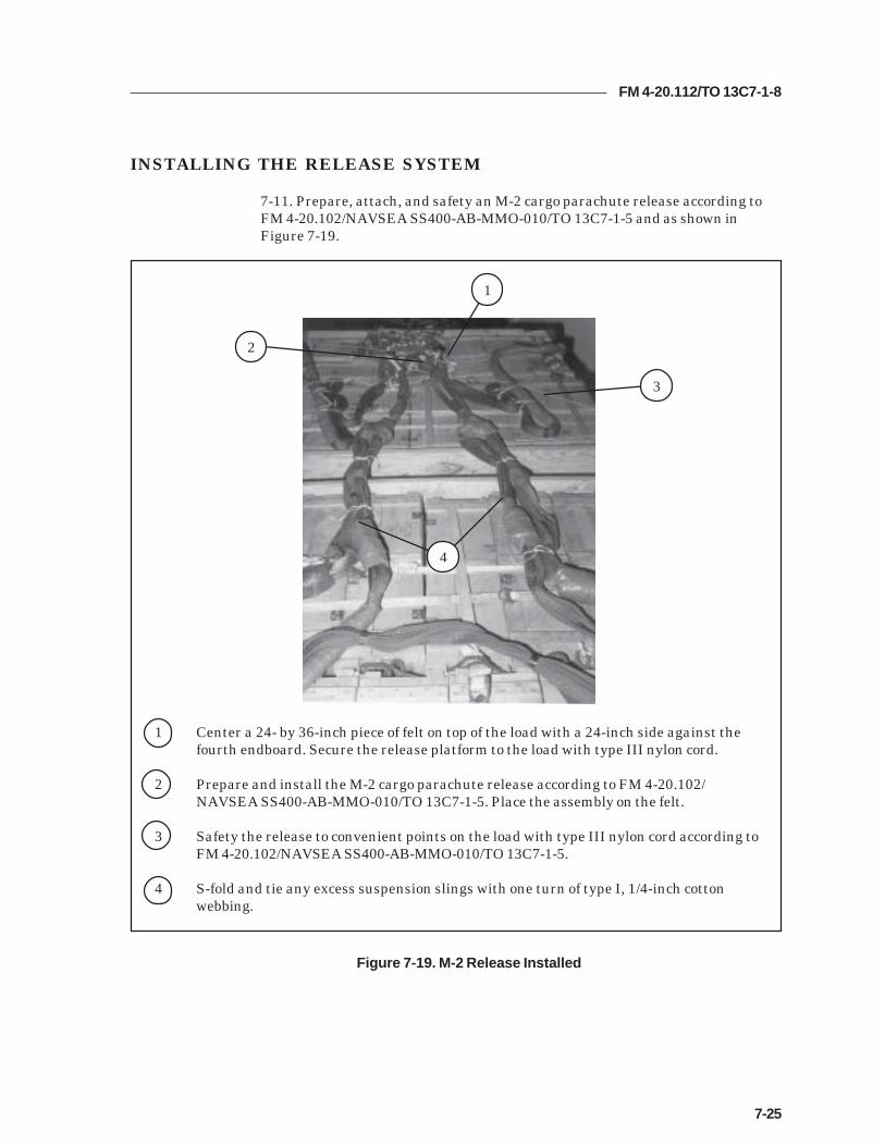
FM 4-20.112/TO 13C7-1-8
7-25
INSTALLING THE RELEASE SYSTEM
7-11. Prepare, attach, and safety an M-2 cargo parachute release according toFM 4-20.102/NAVSEA SS400-AB-MMO-010/TO 13C7-1-5 and as shown inFigure 7-19.
1 Center a 24- by 36-inch piece of felt on top of the load with a 24-inch side against thefourth endboard. Secure the release platform to the load with type III nylon cord.
2 Prepare and install the M-2 cargo parachute release according to FM 4-20.102/NAVSEA SS400-AB-MMO-010/TO 13C7-1-5. Place the assembly on the felt.
3 Safety the release to convenient points on the load with type III nylon cord according toFM 4-20.102/NAVSEA SS400-AB-MMO-010/TO 13C7-1-5.
4 S-fold and tie any excess suspension slings with one turn of type I, 1/4-inch cottonwebbing.
Figure 7-19. M-2 Release Installed
2
1
3
4

FM 4-20.112/TO 13C7-1-8
7-26
INSTALLING THE EXTRACTION SYSTEM
7-12. Install the extraction system according to FM 4-20.102/NAVSEA SS400-AB-MMO-010/TO 13C7-1-5 and as shown in Figure 7-20.
Figure 7-20. Extraction System Installed
1 Install the components of the EFTC according to FM 4-20.102/NAVSEA SS400-AB-MMO-010/TO 13C7-1-5. Use the rear mounting holes for the EFTC brackets.
2 Install a 24-foot EFTC cable according to FM 4-20.102/NAVSEA SS400-AB-MMO-010/TO 13C7-1-5.
3 Attach a 9-foot (2-loop), type XXVI nylon sling according to FM 4-20.102/NAVSEA SS400-AB-MMO-010/TO 13C7-1-5 to be used as a deployment line. S-fold the excess and tie it intwo places with type I, 1/4-inch cotton webbing.
3
1
2

FM 4-20.112/TO 13C7-1-8
7-27
PLACING EXTRACTION PARACHUTE
7-13. Select the extraction parachute and extraction line needed using the extractionline requirements table in FM 4-20.102/ NAVSEA SS400-AB-MMO-010/TO 13C7-1-5.Place the extraction parachute and line on the load for installation in the aircraft.
INSTALLING PROVISIONS FOR EMERGENCY RESTRAINTS
7-14. Select and install the provisions for the emergency aft restraints according tothe emergency aft restraint requirements table in FM 4-20.102/NAVSEA SS400-AB-MMO-010/TO 13C7-1-5.
MARKING RIGGED LOAD
7-15. Mark the rigged load according to FM 4-20.102/NAVSEA SS400-AB-MMO-010/TO 13C7-1-5, and as shown in Figure 7-21. Complete Shipper'sDeclaration for Dangerous Goods. If the load varies from the one shown, the weight,height, CB, and parachute requirements must be recomputed.
EQUIPMENT REQUIRED
7-16. Use the equipment listed in Table 7-1 to rig this load.
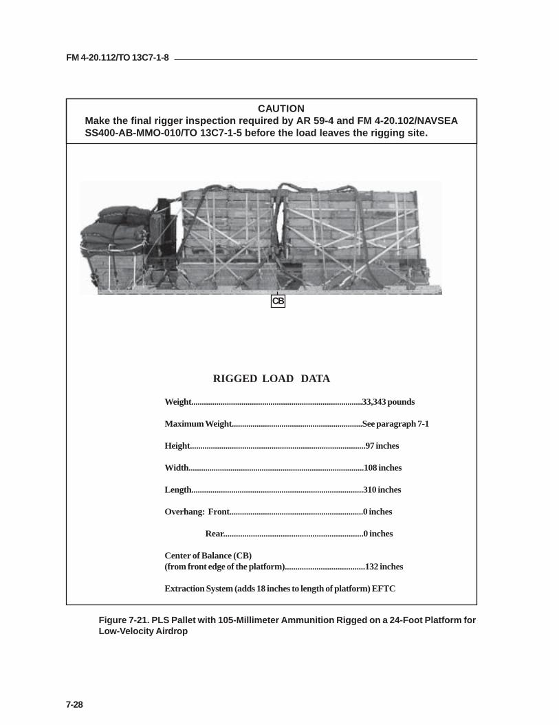
FM 4-20.112/TO 13C7-1-8
7-28
RIGGED LOAD DATA
Weight..................................................................................33,343 pounds
Maximum Weight...............................................................See paragraph 7-1
Height....................................................................................97 inches
Width....................................................................................108 inches
Length..................................................................................310 inches
Overhang: Front................................................................0 inches
Rear..................................................................0 inches
Center of Balance (CB)(from front edge of the platform)......................................132 inches
Extraction System (adds 18 inches to length of platform) EFTC
Figure 7-21. PLS Pallet with 105-Millimeter Ammunition Rigged on a 24-Foot Platform forLow-Velocity Airdrop
CB
CAUTIONMake the final rigger inspection required by AR 59-4 and FM 4-20.102/NAVSEASS400-AB-MMO-010/TO 13C7-1-5 before the load leaves the rigging site.

FM 4-20.112/TO 13C7-1-8
7-29
Table 7-1. Equipment Required for Rigging PLS with 105-Millimeter Ammunition on a24-Foot, Type V Platform for Low-Velocity Airdrop
National Stock Item Quantity Number
8040-00-273-8713 Adhesive paste, 1-gal. As required4030-00-090-5354 Clevis, suspension, 1-inch (large) 144020-00-240-2146 Cord, nylon, type III, 550-lb. As required1670-00-434-5782 Coupling, airdrop extraction force transfer, w/24-ft. cable 11670-00-360-0328 Cover, clevis 78135-00-664-6958 Cushioning material (Cellulose wadding) As required8305-00-958-3685 Felt, 1/2-inch thick As required1670-01-183-2678 Leaf, extraction line (line bag) ( add 2 for C-17) 2
Line extraction:1670-01-062-6313 60-foot (3-loop), type XXVI (for C-130) 11670-01-064-4454 60-foot (6-loop), type XXVI 11670-01-062-6312 120-foot (6-loop), type XXVI (for C-5) 11670-01-468-9178 140-foot (6-loop), type XXVI (for C-17) 11670-01-064-4452 60-foot (1-loop), type XXVI (for C-17), (drogue line) 11670-00-162-4981 Link assembly, four-point 21670-00-162-4981 Link assembly, three-point 2
Link assembly, two-point:5306-00-435-8994 Bolt, 1-inch diameter, 4-inches long (add 4 for C-5) 85310-00-232-5165 Nut, 1-inch (add 4 for C-5) 81670-00-003-1953 Plate, side, 3 3/4-inch 85365-00-007-3414 Spacer, large (add 4 for C-5) 85510-00-220-6146 Lumber, 2- by 4-in As required5310-00-010-4657 Nail, steel wire, common, 6d1670-00-753-3928 Pad, energy-dissipating (honeycomb)
3- by 36- by 96-inches 46 sheets1670-01-016-7841 Parachute, cargo, G-11 7
Parachute, cargo, extraction:1670-00-040-8135 28-ft. 11670-01-063-3715 15-ft. (C-17 only) 1
Platform, airdrop, type V, 24-ft:5530-00-128-4981 Plywood, 3/4- by 48- by 96-in 11 sheets1670-01-162-2372 Clevis assembly (type V) (68)1670-01-353-8424 Extraction bracket assembly (1)1670-01-247-2389 Link, suspension bracket, type V (8)1670-01-162-2381 Link, tandem, suspension link assembly (2)1670-01-097-8817 Release, cargo parachute, M-2 1
Sling, cargo, airdrop:1670-01-064-4453 20-ft. (4-loop), type XXVI 21670-01-062-6307 12-ft. (4-loop), type XXVI 2

FM 4-20.112/TO 13C7-1-8
7-30
Table 7-1. Equipment Required for Rigging PLS with 105-Millimeter Ammunition on a24-Foot, Type V Platform for Low-Velocity Airdrop (Continued)
National Stock Item Quantity Number
1670-01-062-6306 3-ft (4-loop), type XXVI nylon webbing 81670-01-062-6304 9-ft (2-loop), type XXVI nylon webbing 31670-01-063-7761 16-ft (2-loop), type XXVI nylon webbing 21670-01-062-6311 120-ft (2-loop), type XXVI nylon webbing 75340-00-040-8219 Strap, parachute, release, multi-knife 27501-00-266-5016 Tape, adhesive, 2-inch As required1670-00-937-0271 Tiedown assembly, 15-ft. 921670-01-483-8259 Towplate release mechanism (H-block) (C-17 only) 1
Webbing:8305-00-268-2411 Cotton, 1/4-inch, type I As required8305-00-082-5752 Nylon, tubular, 1/2-inch As required8305-00-261-8584 Nylon, type X As required

FM 4-20.112/TO 13C7-1-8
7-31
Section II
RIGGING A-22 CARGO BAGS
DESCRIPTION OF LOAD
7-17. The Palletized Load System can be moved from the drop zone andtransported on a specially designed truck. Bulk supplies are lashed to thepallet, giving the load integrity for transport. The pallet has swivel ringsalong the sides for lashing the load. The pallet is lashed to the airdropplatform for low-velocity airdrop. The load shown consists of eight A-22cargo bags. Adapt these procedures to rig other items of bulk supplies.Ammunition listed in FM 4-20.153/MCPR 4-11.3B/TO 13C7-18-41, ascertified for low-velocity airdrop, may be rigged using these procedures. Therigged load may not be more than 100 inches high. Refer to FM 4-20.102/NAVSEA SS400-AB-MMO-010/TO 13C7-1-5 for the weight limitations forthe number of parachutes to be used.
PREPARING PLATFORM
7-18. Prepare a 24-foot, type V platform as shown in Figure 7-22.

FM 4-20.112/TO 13C7-1-8
7-32
Step:
1. Inspect, or assemble and inspect, a 24-foot, type V platform as outlined in TM 10-1670-268-20&P/TO 13C7-52-22.
2. Install a suspension link in holes 18, 19, and 20 on each side of the platform.
3. Install a suspension link in holes 6, 7, and 8 on each side of the platform.
4. Install a tandem link on the front of each platform side rail using holes 1, 2, and 3.
5. Install a suspension link in holes 29, 30, and 31 on each side of the platform.
6. Install a suspension link in holes 41, 42, and 43 on each side of the platform.
7. Install clevises on bushings 3 and 4 of each front tandem links.
8. Install clevises on bushings 1 and 3 of each first suspension links.
9. Install clevises on bushings 1 and 2 of each second suspension links.
10. Starting at the front of the right and left platform side rail, install clevises on thebushings bolted to holes 4, 14, 17, 23, 35, 37, 38, 45, 46, and 48.
11. Install a double clevis on bushings 4 and 37 on each side of the platform.
12. Starting at the front of the platform, number the clevises 1 through 16 on the rightside, and 1A through 16A on the left side.
Figure 7-22. Platform Prepared
CLEVISES 16 THROUGH 1
CLEVISES 16A THROUGH 1A
REAR FRONT
RIGHT
LEFT

FM 4-20.112/TO 13C7-1-8
7-33
PREPARING AND POSITIONING HONEYCOMB7-19. Prepare ten honeycomb stacks as shown in Figures 7-23 through 7-25.Position the stacks on the platform as shown in Figure 7-26.
Figure 7-23. Stacks 1, 2, 5, and 6 Prepared
* Two- by four-inch lumber is actually 3 1/2 inches wide.
kcatSrebmuN seceiP
htdiW)sehcnI(
htgneL)sehcnI( lairetaM snoitcurtsnI
,2,16dna,5
11
4242
6767
bmocyenoHhcni-4/3doowylp
otbmocyenohrevohsulfdoowylpeulG.esabmrof
3 81 67 bmocyenoH .esabnoeulgdnaretneC
2 81 67 hcni-4/3doowylp
.bmocyenohrevohsulfeulG
7 81 2/13* hcni-4yb-2rebmul
fodnehcaerevohsulfeceipenoliaNeceipdrihtaretneC.doowylpeht
seceipowtecapS.sdneehtneewtebdnaeceipdnehcaeneewtebylneve
.eceipretneceht
1 21 67 hcni-4/3doowylp
.rebmulrevoliandnaretneC
1 6 67 hcni-4/3doowylp
.doowylprevoliandnaretneC

FM 4-20.112/TO 13C7-1-8
7-34
Figure 7-24. Stacks 3 and 4 Prepared
* Two- by four-inch lumber is actually 3 1/2 inches wide.
kcatSrebmuN seceiP
htdiW)sehcnI(
htgneL)sehcnI( lairetaM snoitcurtsnI
4dna3 42
4242
6969
bmocyenoHhcni-4/3doowylp
otbmocyenohrevohsulfdoowylpeulG.esabmrof
9 42 2/13* hcni-4yb-2rebmul
fodnehcaerevohsulfeceipenoliaNeceipdrihtaretneC.doowylpeht
seceipeerhtecapS.sdneehtneewtebehtdnaeceipdnehcaeneewtebylneve
.eceipretnec1 42 69 hcni-4/3
doowylp.rebmulrevoliandnaretneC
1 21 69 hcni-4/3doowylp
.doowylprevoliandnaretneC
1 6 69 hcni-4/3doowylp
.doowylprevoliandnaretneC
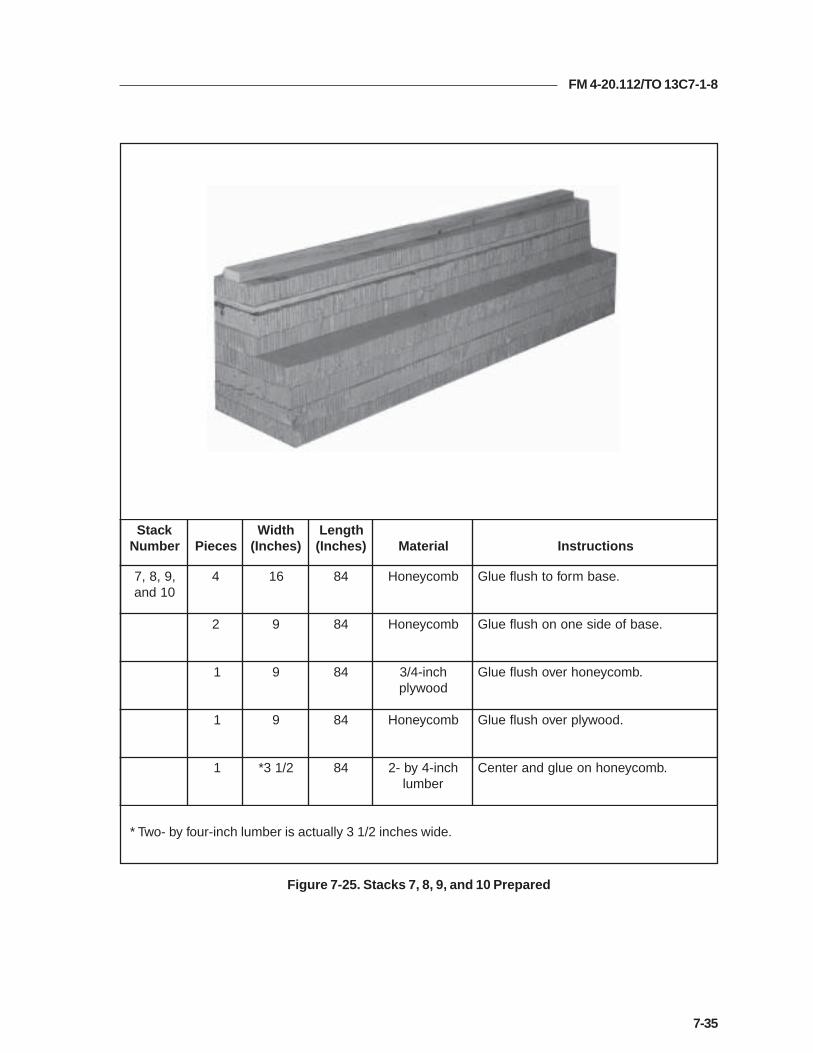
FM 4-20.112/TO 13C7-1-8
7-35
Figure 7-25. Stacks 7, 8, 9, and 10 Prepared
* Two- by four-inch lumber is actually 3 1/2 inches wide.
kcatSrebmuN seceiP
htdiW)sehcnI(
htgneL)sehcnI( lairetaM snoitcurtsnI
,9,8,701dna
4 61 48 bmocyenoH .esabmrofothsulfeulG
2 9 48 bmocyenoH .esabfoedisenonohsulfeulG
1 9 48 hcni-4/3doowylp
.bmocyenohrevohsulfeulG
1 9 48 bmocyenoH .doowylprevohsulfeulG
1 2/13* 48 hcni-4yb-2rebmul
.bmocyenohnoeulgdnaretneC

FM 4-20.112/TO 13C7-1-8
7-36
Figure 7-26. Honeycomb Stacks Positioned on Platform
Notes:1. This drawing is not to scale.2. All dimensions are in inches.
kcatSrebmuN mroftalPehtnokcatSfonoitisoP
1 edisnithgirehtmorfsehcni42dnamroftalpehtfoegdetnorfehthtiwhsulfecalP.egdemroftalp
2 edisnitfelehtmorfsehcni42dnamroftalpehtfoegdetnorfehthtiwhsulfecalP.egdemroftalp
3 .1kcatsdnihebdengiladnatsniagaecalP
4 .2kcatsdnihebdengiladnatsniagaecalP
5 .3kcatsdnihebdengiladnatsniagaecalP
6 .4kcatsdnihebdengiladnatsniagaecalP
7 sedisthgirehthtiwhsulfdnamroftalpehtfoegdetnorfehtmorfsehcni23ecalP.3dna1skcatsfo
8 fosedistfelehthtiwhsulfdnamroftalpehtfoegdetnorfehtmorfsehcni23ecalP.4dna2skcats
9 3skcatsfosedisthgirehthtiwhsulfdna7kcatsforaerehtotsehcni22ecalP.5dna
01 dna4skcatsfosedistfelehthtiwhsulfdna8kcatsforaerehtotsehcni22ecalP.6
10
22 32
24
6 4
8
2
5 3 1
9 7

FM 4-20.112/TO 13C7-1-8
7-37
Figure 7-27. Pallet Prepared
PREPARING PLS PALLET
7-20. Prepare the pallet as shown in Figure 7-27.
1 Tie the storage compartments on each side shut with type III nylon cord.
2 Pad the top of each box area with a 7- by 30-inch piece of felt, a 7- by 30-inch piece ofhoneycomb, and two 7- by 30-inch pieces of felt. Tie the padding in place with lengths oftype III nylon cord.
3 Remove the wheels and secure them in place with the pins provided. Tie the wheels to theirbrackets with a length of 1/2-inch tubular nylon webbing.
4 Pad the fixtures on the outsides of the boxes with cellulose wadding and tape.
1
3
2
4
3

FM 4-20.112/TO 13C7-1-8
7-38
Figure 7-27. Pallet Prepared (Continued)
5 Pad the first, second, third, fifth, and ninth stake brackets on each side with cellulosewadding and tape.
6 Pad all four corners of the PLS pallet around the bottom holes with cellulose wadding andtape as shown.
7 Add a platform clevis to each of the large tie-down brackets at the rear of the PLS pallet.
8 Add two platform clevises on the bracket for sixth swivel ring bracket on each side. Tie theseventh swivel ring to the stake bracket with type I, 1/4-inch cotton webbing.
9 Add three platform clevises to the fourth swivel ring bracket on each side of the PLS pallet.
10 Add two clevises to the eleventh swivel ring bracket on each side of the PLS pallet.
5
67
8
5
5
9
105

FM 4-20.112/TO 13C7-1-8
7-39
Figure 7-28. Pallet Positioned and Restraint Lashing Installed
POSITIONING PLS PALLET ON PLATFORM
7-21. Position the pallet on the platform and install the restraint lashingsaround the honeycomb stacks as shown in Figure 7-28.
1 Center the pallet on the stacks with the yoke assembly to the rear. The rear edge of thepallet must be even with the rear edges of stacks 5 and 6. Be sure that the center runners ofthe pallet rest squarely on stacks 1, 2, 3, 4, 5 and 6. Be sure that the pallet side rails rest onthe lumber portion of stacks 7, 8, 9, and 10.
2 Pass a 15-foot lashing through clevis 4 and through its own D-ring. Pass the lashingthrough the first holes in stacks 1 and 2. Secure the lashing to clevis 4A with a load binder.
3 Pass a 15-foot lashing through clevis 12 and through its own D-ring. Pass the lashingthrough the rear holes in stacks 5 and 6. Secure the lashing to clevis 12A with a loadbinder.
4
12
1
2
3

FM 4-20.112/TO 13C7-1-8
7-40
LASHING PLS PALLET TO PLATFORM
7-22. Lash the PLS pallet to the platform as shown in Figure 7-29.
Figure 7-29. Pallet Lashed to Platform
gnihsaLrebmuN
nwodeiTrebmuNsivelC
snoitcurtsnI
1
2
3
4
5
6
7
8
1
A1
2
A2
3
A3
5
A5
:gnihsalssaP.tniopnwod-eitedisnitnorfthgirehthguorhT
.tniopnwod-eitedisnitnorftfelehthguorhT
.tekcarbekatsdnocesehthguorhT
tekcarbekatsdnocesehthguorhT
.tniopnwod-eitedistuotnorfthgirehthguorhT
.tniopnwod-eitedistuotnorftfelehthguorhT
.gnirleviwstsrifehthguorhT
.gnirleviwstsrifehthguorhT
3
7
1
5
123
45
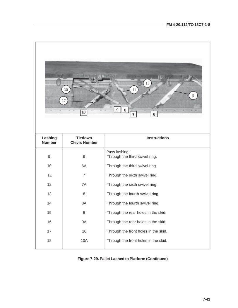
FM 4-20.112/TO 13C7-1-8
7-41
gnihsaLrebmuN
nwodeiTrebmuNsivelC
snoitcurtsnI
9
01
11
21
31
41
51
61
71
81
6
A6
7
A7
8
A8
9
A9
01
A01
:gnihsalssaP.gnirleviwsdrihtehthguorhT
.gnirleviwsdrihtehthguorhT
.gnirleviwshtxisehthguorhT
.gnirleviwshtxisehthguorhT
.gnirleviwshtruofehthguorhT
.gnirleviwshtruofehthguorhT
.diksehtniselohraerehthguorhT
.diksehtniselohraerehthguorhT
.diksehtniselohtnorfehthguorhT
.diksehtniselohtnorfehthguorhT
Figure 7-29. Pallet Lashed to Platform (Continued)
9
13
1115
17
678910
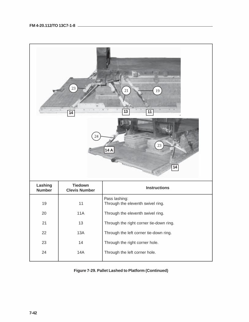
FM 4-20.112/TO 13C7-1-8
7-42
gnihsaLrebmuN
nwodeiTrebmuNsivelC
snoitcurtsnI
91
02
12
22
32
42
11
A11
31
A31
41
A41
:gnihsalssaP.gnirleviwshtneveleehthguorhT
.gnirleviwshtneveleehthguorhT
.gnirnwod-eitrenrocthgirehthguorhT
.gnirnwod-eitrenroctfelehthguorhT
.elohrenrocthgirehthguorhT
.elohrenroctfelehthguorhT
Figure 7-29. Pallet Lashed to Platform (Continued)
14 13 11
14
14 A23
24
192123

FM 4-20.112/TO 13C7-1-8
7-43
PLACING AND LASHING THE LOAD
7-23. Cover the pallet with a layer of honeycomb and place eight A-22 containerson the pallet as shown in Figure 7-30. Construct four endboards as shown inFigure 7-31. Lash the containers and endboards to the front section of the palletas shown in Figure 7-32. Lash the containers and endboards to the rear sectionof the pallet as shown in Figure 7-33.
1 Cover the pallet with six 96- by 36-inch pieces of honeycomb, beginning 4 1/2 inches fromthe front edge. Space the third and fourth pieces 8 inches apart.
2 Place four A-22 containers on the honeycomb, 8 inches from the front edge of the pallet.Allow space for the endboards to rest on the honeycomb.
3 Place four A-22 containers on the second section of honeycomb, at least 8 inches from thecontainers placed in step 2 above. Allow space for the endboards to rest on the honeycomb.
Figure 7-30. Honeycomb and A-22 Containers Placed on the Pallet
3
1
2

FM 4-20.112/TO 13C7-1-8
7-44
3
90
36
9 20 29
Notes:1. This drawing is not to scale.2. All dimensions are in inches.3. For loads different from that shown in this section, make theendboards the same height as the load configuration.4. The instructions given are for one endboard. Four are required forthis load.
2
Step:
1. Cut four 90- by 36-inch pieces of 3/4-inch plywood.
2. Make 2- by 3-inch cutouts as shown. Tape the sharp edges of the cutouts.
3. Place an endboard against the front and rear of each of the two groups of containers. (Notshown)
Figure 7-31. Four Endboards Constructed

FM 4-20.112/TO 13C7-1-8
7-45
gnihsaLrebmuN
rebmuNgniRtellaP snoitcurtsnI
1
2
3
4
1
2otA2
5otA5
ehtotnwod-eittnorfthgirehtmorfgnihsaltoof-03anuRehtdnuoradna,draobdnetnorfehtnituotucelddimtfel
nituotucelddimtfelehthguorhtgnihsalehtssaP.edistfelsivelcdneehtotgnihsalehteruceS.draobdnednoceseht
.edisthgirehtnognirtellaphtxisehtno
ehtotnwod-eittnorftfelehtmorfgnihsaltoof-03anuRehtdnuoradna,draobdnetnorfehtnituotucelddimthgir
tuotucelddimthgirehthguorhtgnihsalehtssaP.edisthgirdneehtotgnihsalehteruceS.draobdnednocesehtni
.edistfelehtnognirtellaphtxisehtnosivelc
.sreniatnocowttsrifehtfospotehtrevognihsalehtnuR
owtdnocesehtfospotehtrevognihsalehtnuR.sreniatnoc
Note:Secure all lashings to the pallet with load binders.
Figure 7-32. First Four Containers Lashed to Pallet
21
3
4
5
2

FM 4-20.112/TO 13C7-1-8
7-46
gnihsaLrebmuN
rebmuNgniRtellaP snoitcurtsnI
5
6
7
8
9
01
2otA2
A4dna4
A5dna5
5otA5
A4dna4
A2dna2
edishcaenognirtellapdnocesehtmorfgnihsalanuR.draobdnetsrifehtnistuotucrewolehthguorht
ehtnosesivelcdneehtfoenomorfgnihsaltoof-03anuRstuotucelddimehthguorhtedishcaenognirtellaphtruof
.draobdnetsrifehtni
htobnognirtellaphtfifehtmorfgnihsaltoof-03anuR.draobdnetsrifehtnistuotucreppuehthguorhtsedis
edishcaenognirtellaphtfifehtmorfgnihsalanuR.draobdnednocesehtnistuotucrewolehthguorht
ehtnosivelcdnegniniamerehtmorfgnihsaltoof-03anuRstuotucelddimehthguorhtedishcaenognirtellaphtruof
.draobdnednocesehtno
hcaenognirtellapdnocesehtmorfgnihsaltoof-03anuR.draobdnednocesehtnistuotucreppuehthguorhtedis
Note:Secure all lashings to the pallet with load binders.
Figure 7-32. First Four Containers Lashed to Pallet (Continued)
5 4 2
7
6
5
9
10
8

FM 4-20.112/TO 13C7-1-8
7-47
gnihsaLrebmuN
rebmuNgniRtellaP snoitcurtsnI
11
21
31
41
11dna6
A11dnaA6
8otA8
01otA01
htxisehtnosivelcdneehtmorfgnihsaltoof-03anuR,draobdnedrihtehtnituotucelddimtfelehtotgnirtellaptfelehthguorhtgnihsalehtssaP.edistfelehtdnuoradnaotgnihsalehteruceS.draobdneraerehtottuotucelddim.edisthgirehtnognirtellaphtneveleehtnosivelcdneeht
htxisehtnosivelcdneehtmorfgnihsaltoof-03anuRdrihtehtnituotucelddimthgirehtotgnirtellap
gnihsalehtssaP.edisthgirehtdnuoradna,draobdne.draobdneraerehtottuotucelddimthgirehthguorht
tellaphtneveleehtnosivelcdneehtotgnihsalehteruceS.edistfelehtnognir
.sreniatnocowttsrifehtfospotehtrevognihsalehtnuR
owtdnocesehtfospotehtrevognihsalehtnuR.sreniatnoc
Figure 7-33. Second Four Containers Lashed to Pallet
Note:Secure all lashings to the pallet with load binders.
14 12 13
1110
8 6
11

FM 4-20.112/TO 13C7-1-8
7-48
Note:1. Secure all lashings to the pallet with load binders.
Figure 7-33. Second Four Containers Lashed to Pallet (Continued)
16
15
1720
19
18
10 9 8
gnihsaLrebmuN
rebmuNgniRtellaP snoitcurtsnI
51
61
71
81
91
02
A8dna8
A9dna9
A01dna01
A01dna01
A9dna9
A8dna8
edishcaenognirtellaphthgieehtmorfgnihsalanuR.draobdnedrihtehtnistuotucrewolehthguorht
hcaenognirtellaphtninehtmorfgnihsaltoof-03anuR.draobdnedrihtehtnistuotucelddimehthguorhtedis
htobnognirtellaphtnetehtmorfgnihsaltoof-03anuR.draobdnedrihtehtnistuotucreppuehthguorhtsedis
edishcaenognirtellaphtnetehtmorfgnihsalanuR.draobdneraerehtnistuotucrewolehthguorht
hcaenognirtellaphtninehtmorfgnihsaltoof-03anuR.draobdneraerehtnistuotucelddimehthguorhtedis
hcaenognirtellaphthgieehtmorfgnihsaltoof-03anuR.draobdneraerehtnistuotucreppuehthguorhtedis
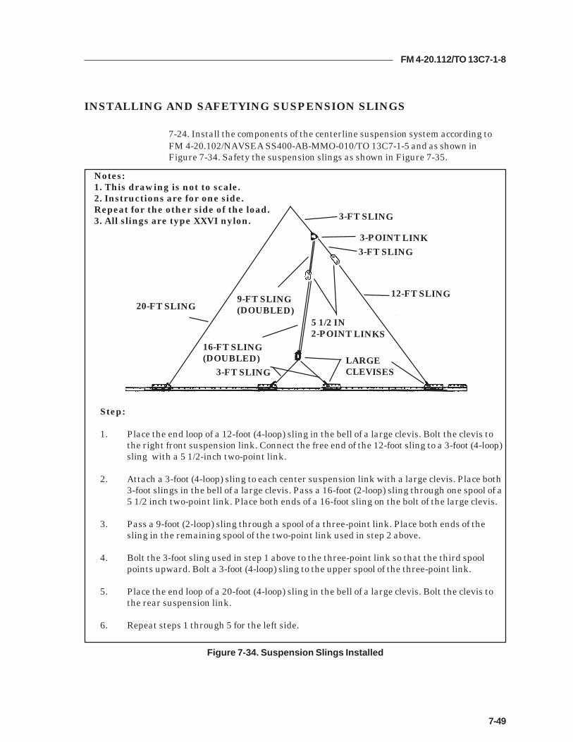
FM 4-20.112/TO 13C7-1-8
7-49
Figure 7-34. Suspension Slings Installed
INSTALLING AND SAFETYING SUSPENSION SLINGS
7-24. Install the components of the centerline suspension system according toFM 4-20.102/NAVSEA SS400-AB-MMO-010/TO 13C7-1-5 and as shown inFigure 7-34. Safety the suspension slings as shown in Figure 7-35.
Step:
1. Place the end loop of a 12-foot (4-loop) sling in the bell of a large clevis. Bolt the clevis tothe right front suspension link. Connect the free end of the 12-foot sling to a 3-foot (4-loop)sling with a 5 1/2-inch two-point link.
2. Attach a 3-foot (4-loop) sling to each center suspension link with a large clevis. Place both3-foot slings in the bell of a large clevis. Pass a 16-foot (2-loop) sling through one spool of a5 1/2 inch two-point link. Place both ends of a 16-foot sling on the bolt of the large clevis.
3. Pass a 9-foot (2-loop) sling through a spool of a three-point link. Place both ends of thesling in the remaining spool of the two-point link used in step 2 above.
4. Bolt the 3-foot sling used in step 1 above to the three-point link so that the third spoolpoints upward. Bolt a 3-foot (4-loop) sling to the upper spool of the three-point link.
5. Place the end loop of a 20-foot (4-loop) sling in the bell of a large clevis. Bolt the clevis tothe rear suspension link.
6. Repeat steps 1 through 5 for the left side.
Notes:1. This drawing is not to scale.2. Instructions are for one side.Repeat for the other side of the load.3. All slings are type XXVI nylon. 3-FT SLING
3-POINT LINK
12-FT SLING
5 1/2 IN2-POINT LINKS
16-FT SLING(DOUBLED)
20-FT SLING
LARGECLEVISES
9-FT SLING(DOUBLED)
3-FT SLING
3-FT SLING

FM 4-20.112/TO 13C7-1-8
7-50
Figure 7-35. Suspension Slings Safetied
1 Pad the two-point and three-point links with felt and tape. Raise the suspension slings.
2 Pad the suspension slings where they pass over the corners of the load with felt and tape.
3 Tie a length of type III nylon cord to the center clevis on one side. Pass the cord over theload, and tie it to the center clevis on the other side so that both clevises are supported.
4 Tie the front suspension slings to each other 12 inches above the load with 1/2-inchtubular nylon webbing as shown in the appendix in the back of this manual.
5 Tie the rear suspension slings to each other 12 inches above the load with 1/2-inchtubular nylon webbing as shown in the appendix in the back of this manual.
1
243
5
2

FM 4-20.112/TO 13C7-1-8
7-51
BUILDING PARACHUTE STOWAGE PLATFORM AND INSTALLINGCARGO PARACHUTES
7-25. Build the parachute stowage platform and install the G-11 cargoparachutes as shown in Figure 7-36.
1 Alternate and glue two 96- by 36-inch and two 96- by 6-inch pieces of honeycomb to forma two-layer base 96 by 42 inches. Cut a channel in the bottom layer of honeycomb toaccommodate the EFTC cable.
2 Alternate and glue two 96- by 36-inch and two 96- by 8-inch pieces of honeycomb to formtwo 96- by 44-inch pieces. Place these layers over the base and flush with the front edge.
3 Alternate and glue two 96- by 36-inch and two 96- by 10-inch pieces of honeycomb to formtwo 96- by 46-inch pieces. Place these layers over the base and flush with the front edge.
4 Cut the front corners of the honeycomb placed in steps 1, 2, and 3 above to allow for thelashings.
5 Alternate and glue two 96- by 36-inch and two 96- by 12-inch pieces of honeycomb to formtwo 96- by 48-inch pieces. Place these layers over the base and flush with the front edge.
6 Secure the parachute stowage platform to the rails with a length of type VIII webbing tiedto the fourth bushing on each rear suspension link, and to bushing 48 on each side.
Figure 7-36. Parachute Stowage Platform Built and Cargo Parachutes Installed
1
2
3
5
6
4

FM 4-20.112/TO 13C7-1-8
7-52
7 Prepare, position, and stow five G-11 cargo parachutes on the parachute stowageplatform according to FM 4-20.102/ NAVSEA SS400-AB-MMO-010/TO 13C7-1-5.
8 Install the rear cargo parachute restraints according to FM 4-20.102/ NAVSEA SS400-AB-MMO-010/TO 13C7-1-5 using type VIII nylon webbing to clevises 16 and 16A.
9 Install the front cargo parachute restraints according to FM 4-20.102/ NAVSEA SS400-AB-MMO-010/TO 13C7-1-5 using type VIII nylon webbing to clevises 15 and 15A.
10 Install the parachute release straps according to FM 4-20.102/ NAVSEA SS400-AB-MMO-010/TO 13C7-1-5.
Figure 7-36. Parachute Stowage Platform Built and Cargo Parachutes Installed (Continued)
7
10
8
9
16A
16
15

FM 4-20.112/TO 13C7-1-8
7-53
INSTALLING THE PARACHUTE RELEASE SYSTEM
7-26. Prepare, attach, and safety an M-2 cargo parachute release according toFM 4-20.102/NAVSEA SS400-AB-MMO-010/TO 13C7-1-5 and as shown inFigure 7-37.
1 Center a 24- by 36-inch piece of honeycomb on top of the load between the third and fourthendboards. Secure the honeycomb to the load with type III nylon cord.
2 Prepare and install the M-2 cargo parachute release according to FM 4-20.102/NAVSEA SS400-AB-MMO-010/TO 13C7-1-5. Place the assembly on the honeycomb.
3 Safety the release to convenient points on the load with type III nylon cord according toFM 4-20.102/NAVSEA SS400-AB-MMO-010/TO 13C7-1-5.
4 S-fold and tie any excess suspension slings with one turn of type I, 1/4-inch cottonwebbing.
Figure 7-37. M-2 Release Installed
12
3
4

FM 4-20.112/TO 13C7-1-8
7-54
INSTALLING THE EXTRACTION SYSTEM
7-27. Install the extraction system according to FM 4-20.102/NAVSEA SS400-AB-MMO-010/TO 13C7-1-5 and as shown in Figure 7-38.
Figure 7-38. Extraction System Installed
1 Install the components of the EFTC according to FM 4-20.102/NAVSEA SS400-AB-MMO-010/TO 13C7-1-5. Use the rear mounting holes for the EFTC brackets.
2 Install a 24-foot EFTC cable according to FM 4-20.102/NAVSEA SS400-AB-MMO-010/TO 13C7-1-5.
3 Attach a 9-foot (2-loop), type XXVI nylon sling according to FM 4-20.102/NAVSEA SS400-AB-MMO-010/TO 13C7-1-5 to be used as a deployment line. S-fold the excess and tie it intwo places with type I, 1/4-inch cotton webbing.
3
1
2

FM 4-20.112/TO 13C7-1-8
7-55
PLACING EXTRACTION PARACHUTE
7-28. Select the extraction parachute and extraction line needed using the extractionline requirements table in FM 4-20.102/ NAVSEA SS400-AB-MMO-010/TO 13C7-1-5.Place the extraction parachute and line on the load for installation in the aircraft.
INSTALLING PROVISIONS FOR EMERGENCY RESTRAINTS
7-29. Select and install the provisions for the emergency aft restraints according tothe emergency aft restraint requirements table in FM 4-20.102/NAVSEA SS400-AB-MMO-010/TO 13C7-1-5.
MARKING RIGGED LOAD
7-30. Mark the rigged load according to FM 4-20.102/NAVSEA SS400-AB-MMO-010/TO 13C7-1-5, and as shown in Figure 7-39. Complete Shipper'sDeclaration for Dangerous Goods. If the load varies from the one shown, the weight,height, CB, and parachute requirements must be recomputed.
EQUIPMENT REQUIRED
7-31. Use the equipment listed in Table 7-2 to rig this load.

FM 4-20.112/TO 13C7-1-8
7-56
RIGGED LOAD DATA
Weight..................................................................................24,278 pounds
Maximum Weight...............................................................See paragraph 7-17
Height....................................................................................84 inches
Width....................................................................................108 inches
Length..................................................................................288 inches
Overhang: Front................................................................0 inches
Rear..................................................................0 inches
Center of Balance (CB)(from front edge of the platform)......................................137 inches
Extraction System (adds 18 inches to length of platform) EFTC
Figure 7-39. PLS Pallet with A-22 Containers Rigged on a 24-Foot Platform for Low-Velocity Airdrop
CB
CAUTIONMake the final rigger inspection required by AR 59-4 and FM 4-20.102/NAVSEASS400-AB-MMO-010/TO 13C7-1-5 before the load leaves the rigging site.

FM 4-20.112/TO 13C7-1-8
7-57
Table 7-2. Equipment Required for Rigging PLS with A-22 Cargo Bags on a 24-Foot, Type VPlatform for Low-Velocity Airdrop
National Stock Item Quantity Number
8040-00-273-8713 Adhesive paste, 1-gal. As required1670-00-587-3421 Bag, cargo, (A-22) 84030-00-090-5354 Clevis, suspension, 1-inch (large) 134020-00-240-2146 Cord, nylon, type III, 550-lb. As required1670-00-434-5782 Coupling, airdrop extraction force transfer, w/24-ft. cable 11670-00-360-0328 Cover, clevis 58135-00-664-6958 Cushioning material (Cellulose wadding) As required8305-00-958-3685 Felt, 1/2-inch thick As required1670-01-183-2678 Leaf, extraction line (line bag) ( add 2 for C-17) 2
Line extraction:1670-01-062-6313 60-foot (3-loop), type XXVI (for C-130) 11670-01-064-4454 60-foot (6-loop), type XXVI 11670-01-062-6312 120-foot (6-loop), type XXVI (for C-5) 11670-01-468-9178 140-foot (6-loop), type XXVI (for C-17) 11670-01-064-4452 60-foot (1-loop), type XXVI (for C-17), (drogue line) 11670-00-162-4981 Link assembly, four-point 21670-00-162-4981 Link assembly, three-point 2
Link assembly, two-point:5306-00-435-8994 Bolt, 1-inch diameter, 4-inches long (add 4 for C-5) 105310-00-232-5165 Nut, 1-inch (add 4 for C-5) 101670-00-003-1953 Plate, side, 3 3/4-inch 105365-00-007-3414 Spacer, large (add 4 for C-5) 105510-00-220-6146 Lumber, 2- by 4-in As required5310-00-010-4657 Nail, steel wire, common, 6d As required1670-00-753-3928 Pad, energy-dissipating (honeycomb)
3- by 36- by 96-inches 44 sheets1670-01-016-7841 Parachute, cargo, G-11 5
Parachute, cargo, extraction:1670-00-040-8135 28-ft. 11670-01-063-3715 15-ft. (C-17 only) 1
Platform, airdrop, type V, 24-ft:5530-00-128-4981 Plywood, 3/4- by 48- by 96-in 7 sheets1670-01-162-2372 Clevis assembly (type V) (48)1670-01-353-8424 Extraction bracket assembly (1)1670-01-247-2389 Link, suspension bracket, type V (8)1670-01-162-2381 Link, tandem, suspension link assembly (2)1670-01-097-8817 Release, cargo parachute, M-2 1
Sling, cargo, airdrop:1670-01-064-4453 20-ft. (4-loop), type XXVI 21670-01-062-6307 12-ft. (4-loop), type XXVI 2

FM 4-20.112/TO 13C7-1-8
7-58
Table 7-2. Equipment Required for Rigging PLS with A-22 Cargo Bags on a 24-Foot, Type VPlatform for Low-Velocity Airdrop (Continued)
National Stock Item Quantity Number
1670-01-062-6306 3-ft (4-loop), type XXVI nylon webbing 81670-01-062-6304 9-ft (2-loop), type XXVI nylon webbing 31670-01-063-7761 16-ft (2-loop), type XXVI nylon webbing 21670-01-062-6311 120-ft (2-loop), type XXVI nylon webbing 75340-00-040-8219 Strap, parachute, release, multi-knife 27501-00-266-5016 Tape, adhesive, 2-inch As required1670-00-937-0271 Tiedown assembly, 15-ft. 581670-01-483-8259 Towplate release mechanism (H-block) (C-17 only) 1
Webbing:8305-00-268-2411 Cotton, 1/4-inch, type I As required8305-00-082-5752 Nylon, tubular, 1/2-inch As required8305-00-263-3598 Nylon, type VIII As required

FM 4-20.112/TO 13C7-1-8
8-1
Chapter 8
RIGGING 155-MILLIMETER (MM) AMMUNITION MODULARARTILLERY CHARGE SYSTEM (MACS) ON A 16-FOOT,
TYPE V PLATFORM FOR LOW-VELOCITY AIRDROP
DESCRIPTION OF LOAD
8-1. Ninety-six 155-mm projectiles and 72 power canisters are rigged forlow-velocity airdrop on a 16-foot, type V platform. The load uses three G-11Bcargo parachutes. Refer to FM 4-20.102/NAVSEA SS400-AB-MMO-010/TO13C7-1-5 for the weight limitations and for the number of parachutes to beused.
Notes:1. The load shown is using metal crates. However, wooden crates maybe used with three lashings and a load binder.2. If the metal locking rods are missing, three lashings, D-rings andload binders will be needed.
PREPARING PLATFORM
8-2. Prepare a 16-foot, type V platform as shown in Figure 8-1.

FM 4-20.112/TO 13C7-1-8
8-2
Step:
1. Inspect, or assemble and inspect, a 16-foot, type V platform as outlined in TM 10-1670-268-20&P/TO 13C7-52-22.
2. Install a tandem link to the front of each platform side rail using holes 1, 2, and 3.
3. Install a tandem link to the rear of each platform side rail using holes 30, 31, and32.
4. Install clevises on bushings 2 and 3 of each front tandem link.
5. Install clevises on bushings 1 and 3 of each rear tandem link.
6. Starting at the front of the right platform side rail, install clevises on the bushingsbolted to holes 4, 6, 9, 10, 11, 12, 13, 15, 16, 17, 18, 19, 20, 22, 23, 24, 25, and 29.
7. Starting at the front of the platform, number the clevises 1 through 22 on the rightside, and 1A through 22A on the left side.
8. Label the tiedown rings according to FM 4-20.102/NAVSEA SS400-AB-MMO-010/TO 13C7-1-5.
Figure 8-1. Platform Prepared
CLEVISES 22A THROUGH 1A
CLEVISES 22 THROUGH 1
FRONTREAR

FM 4-20.112/TO 13C7-1-8
8-3
Figure 8-2. Honeycomb Stacks 1 and 2 Prepared and Stack 1 Positioned on the Platform
BUILDING HONEYCOMB STACKS 1 AND 2 AND POSITIONINGSTACK 1
8-3. Prepare honeycomb stacks 1 and 2 and position stack 1 as shown in Figure8-2.
1 Position stack 1 centered 6 inches from the front edge of the platform.
1
FRONT
kcatSrebmuN seceiP
htdiW)sehcnI(
htgneL)sehcnI( lairetaM snoitcurtsnI
2dna1 2 63 88 bmocyenoH gnolsehcni88esabreyalowtamroFehtetanretlA.ediwsehcni06dna
kcatsehtretneC.bmocyenohfosreyalehtfoegdetnorfehtmorfsehcni6
.mroftalp
2 42 88 bmocyenoH .petstsrifehthtiwdedulcnI
8 51 5 bmocyenoH nobmocyenohfoseceipowtecalPhcni-5ehthtiwesabehtforenrochcae
fosedisthgirdnatfelehtgnicafsedis.mroftalpeht
4 51 01 bmocyenoH gnolabmocyenohfoseceipowtretneChcni-01ehthtiwesabehtfoedishcaefosedisthgirdnatfelehtgnicafsedis
.mroftalpeht
61 51 01 bmocyenoH foseceipreyalowtecapsylnevEdnaretnecehtneewtebbmocyenoh
ehtneewtebsecapsehT.seceiprenroc.sehcni2/14eraseceip

FM 4-20.112/TO 13C7-1-8
8-4
POSITIONING AND SECURING THE FIRST AMMUNITION STACK
8-4. Position and secure the first ammunition stack as shown in Figure 8-3.
Figure 8-3. Ammunition Positioned and Secured
2 Position three sets of projectiles flush on the honeycomb on each side. Fit the skids at thebottom of the bundles into the slots in the honeycomb stack.
2
2
1 Tie the four center eyelets of each bundle together with 1-inch tubular nylon webbing forlifting purposes only.
1

FM 4-20.112/TO 13C7-1-8
8-5
Figure 8-3. Ammunition Positioned and Secured (Continued)
3 Place a 15-foot tiedown lashing 8 inches from the front and rear edge of honeycomb stack 1in a right to left direction.
4 Place a 15-foot tiedown lashing 24 inches from the front and rear edge of honeycomb stack 1in a right to left direction.
3
3
4

FM 4-20.112/TO 13C7-1-8
8-6
Figure 8-3. Ammunition Positioned and Secured (Continued)
5 Position four powder canisters on each of the pre-positioned lashings with the canisteropenings to the center.
6 Place a 30- by 27-inch piece of honeycomb over each group of four canisters.
7 Place a second layer of powder canisters on top of the 30- by 27-inch piece of honeycombwhich was placed over each group.
8 Place a second layer of 30- by 27-inch honeycomb over the second layer of each canistergroup.
9 Place a third layer of four powder canisters on top of the 30- by 27-inch piece of honeycombover each group.
10 Secure the pre-positioned lashings over the canisters. Pad the area between the canistersand the load binders with a piece of felt.
5
5 5
67
7 78
8
9
9 10
10

FM 4-20.112/TO 13C7-1-8
8-7
11 Cut four 24- by 24-inch pieces of honeycomb and place them between the canisters to forma box.
12 Place six fuse cans in the honeycomb box.
13 Cut an 18- by 24-inch piece of honeycomb and position it over the fuse cans. (Not shown)
14 Place six fuse cans on top of the 18- by 24-inch piece of honeycomb.
15 Cut two 18- by 24-inch pieces of honeycomb and place on top of the second layer of fuse cansto fill the empty space in the honeycomb box. (Not shown)
Figure 8-3. Ammunition Positioned and Secured (Continued)
16 Cut and center a 30- by 88-inch piece of honeycomb over the canisters.
11
12
14
16

FM 4-20.112/TO 13C7-1-8
8-8
CONSTRUCTING ENDBOARDS
8-5. Construct four endboards as shown in Figure 8-4.
Figure 8-4. Endboards Constructed
Step:
1. Cut eight 3/4- by 60- by 38-inch pieces of plywood.
2. Cut 2- by 3-inch cutouts as shown.
3. Nail two pieces of plywood flush together with 6d nails to make the four endboards.
4. Pad the cutouts with cellulose wadding and tape.
23
60
38
24
6
12
Notes: 1. All measurements are given in inches. 2. This drawing is not drawn to scale.

FM 4-20.112/TO 13C7-1-8
8-9
LASHING THE FIRST AMMUNITION STACK AND USING THE FIRSTAND SECOND ENDBOARDS
8-6. Lash the first ammunition stack and use the first and second endboards asshown in Figure 8-5.
Figure 8-5. First Ammunition Stack Lashed Using the First and Second Endboards
4
2 1
678
34
gnihsaLrebmuN
nwodeiTrebmuNsivelC
snoitcurtsnI
1 A4dna4 hguorhtdnasesivelchtobhguorhtgnihsaltoof-03assaPeruceS.draobdnetnorfehtfopotehtmorftuo-tucdrihteht
adnasgnir-Dowthtiwedisthgirtnorfehtotgnihsaleht.rednibdaol
2 A6dna6 hguorhtdnasesivelchtobhguorhtgnihsaltoof-03assaP.draobdnetnorfehtfopotehtmorftuo-tucdnoceseht
sgnir-DowthtiwedisthgirtnorfehtotgnihsalehteruceS.rednibdaoladna
3 A7dna7 hguorhtdnasesivelchtobhguorhtgnihsaltoof-03assaPeruceS.draobdneraerehtfopotehtmorftuo-tucpoteht
daoladnasgnir-Dowthtiwedisthgirehtotgnihsaleht.rednib
4 A8dna8 hguorhtdnasesivelchtobhguorhtgnihsaltoof-03assaPeruceS.draobdneraerehtfopotehtmorftuo-tucdrihteht
daoladnasgnir-Dowthtiwedisthgirehtotgnihsaleht.rednib

FM 4-20.112/TO 13C7-1-8
8-10
Figure 8-5. First Ammunition Stack Lashed Using the First and Second Endboards (Continued)
gnihsaLrebmuN
nwodeiTrebmuNsivelC
snoitcurtsnI
5 01dna1 stihguorhtdna1sivelchguorhtgnihsaltoof-51aetuoRtuo-tucdnocesehthguorhtgnihsalehtetuoR.gnir-DnwoaetuoR.edistfelehtfodraobdnetnorfehtfopotehtmorf
-Dnwostihguorhtdna01sivelchguorhtgnihsaltoof-51morftuo-tucdnocesehthguorhtgnihsalehtetuoR.gnir
ahtiweruceS.edistfelehtnodraobdneraerehtfopoteht.edistfelehtnosgnir-Ddnarednibdaol
6 A01dnaA1 stihguorhtdnaA1sivelchguorhtgnihsaltoof-51aetuoRtuo-tucdnocesehthguorhtgnihsalehtetuoR.gnir-Dnwo
etuoR.edisthgirehtfodraobdnetnorfehtfopotehtmorfnwostihguorhtdnaA01sivelchguorhtgnihsaltoof-51amorftuo-tucdnocesehthguorhtgnihsalehtetuoR.gnir-DhtiweruceS.edisthgirehtnodraobdneraerehtfopoteht
.edisthgirehtnosgnir-Ddnarednibdaola
7 11dna2 stihguorhtdna2sivelchguorhtgnihsaltoof-51aetuoRtuo-tucdrihtehthguorhtgnihsalehtetuoR.gnir-Dnwo
aetuoR.edistfelehtfodraobdnetnorfehtfopotehtmorf-Dnwostihguorhtdna11sivelchguorhtgnihsaltoof-51ehtmorftuo-tucdrihtehthguorhtgnihsalehtetuoR.gnir
ahtiweruceS.edistfelehtnodraobdneraerehtfopot.edistfelehtnosgnir-Ddnarednibdaol
8 A11dnaA2 stihguorhtdnaA2sivelchguorhtgnihsaltoof-51aetuoRtuo-tucdrihtehthguorhtgnihsalehtetuoR.gnir-Dnwo
etuoR.edisthgirehtfodraobdnetnorfehtfopotehtmorfnwostihguorhtdnaA11sivelchguorhtgnihsaltoof-51a
ehtmorftuo-tucdrihtehthguorhtgnihsalehtetuoR.gnir-DahtiweruceS.edisthgirehtnodraobdneraerehtfopot
.edisthgirehtnosgnir-Ddnarednibdaol
11011 2
7 5
5
7
6
8

FM 4-20.112/TO 13C7-1-8
8-11
Figure 8-5. First Ammunition Stack Lashed Using the First and Second Endboards (Continued)
359
91011
gnihsaLrebmuN
nwodeiTrebmuNsivelC
snoitcurtsnI
9 A3dna3 ehtrevodnasesivelchtobhguorhtgnihsaltoof-03assaPhtiwedisthgirehtnognihsalehteruceS.daolehtfopot
.rednibdaoladnasgnir-Dowt
01 A5dna5 ehtrevodnasesivelchtobhguorhtgnihsaltoof-03assaPhtiwedisthgirehtnognihsalehteruceS.daolehtfopot
.rednibdaoladnasgnir-Dowt
11 A9dna9 ehtrevodnasesivelchtobhguorhtgnihsaltoof-03assaPhtiwedisthgirehtnognihsalehteruceS.daolehtfopot
.rednibdaoladnasgnir-Dowt

FM 4-20.112/TO 13C7-1-8
8-12
POSITIONING STACK 2 AND POSITIONING AND SECURING THESECOND AMMUNITION STACK
8-7. Position honeycomb stack 2 and position and secure the second ammunitionstack as shown in Figure 8-6.
Figure 8-6. Honeycomb Stack 2 Positioned and the Second Ammunition Stack Positionedand Secured
2 Position stack 2 six inches and centered from the rear edge of the platform.
2
1 Tie the four center eyelets of each bundle together with 1-inch tubular nylon webbing forlifting purposes only.
1

FM 4-20.112/TO 13C7-1-8
8-13
3 Position three sets of projectiles flush on the honeycomb on each side. Fit the skids at thebottom of the bundles into the slots in the honeycomb stack.
3
Figure 8-6. Honeycomb Stack 2 Positioned and the Second Ammunition Stack Positionedand Secured (Continued)
4 Place a 15-foot tiedown lashing 8 inches from the front and rear edge of honeycomb stack 2in a right to left direction.
5 Place a 15-foot tiedown lashing 24 inches from the front and rear edge of honeycomb stack 2in a right to left direction.
4
4
5

FM 4-20.112/TO 13C7-1-8
8-14
Figure 8-6. Honeycomb Stack 2 Positioned and the Second Ammunition Stack Positionedand Secured (Continued)
6 Position four powder canisters on each of the pre-positioned lashings with the canisteropenings to the center.
7 Place a 30- by 27-inch piece of honeycomb over each group of four canisters.
8 Place a second layer of powder canisters on top of the 30- by 27-inch piece of honeycombwhich was placed over each group.
9 Place a second layer of 30- by 27-inch honeycomb over the second layer of each canistergroup.
10 Place a third layer of four powder canisters on top of the 30- by 27-inch piece of honeycombover each group.
11 Secure the pre-positioned lashings over the canisters with two D-rings and a load binder.Pad the area between the canisters and the load binders with a piece of felt.
12 Cut eight 30- by 30-inch pieces of honeycomb and place them in between the powdercanisters.
6 78
9
10
11
11
10
12

FM 4-20.112/TO 13C7-1-8
8-15
Figure 8-6. Honeycomb Stack 2 Positioned and the Second Ammunition Stack Positionedand Secured (Continued)
13 Cut and center a 30- by 88-inch piece of honeycomb over the canisters.
13

FM 4-20.112/TO 13C7-1-8
8-16
LASHING THE SECOND AMMUNITION STACK AND USING THETHIRD AND FOURTH ENDBOARDS
8-8. Lash the second ammunition stack and use the third and fourth endboardsas shown in Figure 8-7.
Figure 8-7. Second Ammunition Stack Lashed Using the Third and Fourth Endboards
1516
1719
121314
15
gnihsaLrebmuN
nwodeiTrebmuNsivelC
snoitcurtsnI
21 A51dna51 hguorhtdnasesivelchtobhguorhtgnihsaltoof-03assaPeruceS.draobdnetnorfehtfopotehtmorftuo-tucdrihteht
adnasgnir-Dowthtiwedistfeltnorfehtotgnihsaleht.rednibdaol
31 A61dna61 hguorhtdnasesivelchtobhguorhtgnihsaltoof-03assaPeruceS.draobdnetnorfehtfopotehtmorftuo-tucdrihteht
adnasgnir-Dowthtiwedistfeltnorfehtotgnihsaleht.rednibdaol
41 A71dna71 hguorhtdnasesivelchtobhguorhtgnihsaltoof-03assaPeruceS.draobdnetnorfehtfopotehtmorftuo-tucdrihteht
adnasgnir-Dowthtiwedistfeltnorfehtotgnihsaleht.rednibdaol
51 A91dna91 hguorhtdnasesivelchtobhguorhtgnihsaltoof-03assaPeruceS.draobdnetnorfehtfopotehtmorftuo-tucdrihteht
adnasgnir-Dowthtiwedistfeltnorfehtotgnihsaleht.rednibdaol

FM 4-20.112/TO 13C7-1-8
8-17
Figure 8-7. Second Ammunition Stack Lashed Using the Third and Fourth Endboards(Continued)
13 12 162122
18
16
18
17
19
17
19
2122
16
18
gnihsaLrebmuN
nwodeiTrebmuNsivelC
snoitcurtsnI
5 01dna1 stihguorhtdna1sivelchguorhtgnihsaltoof-51aetuoRtuo-tucdnocesehthguorhtgnihsalehtetuoR.gnir-DnwoaetuoR.edistfelehtfodraobdnetnorfehtfopotehtmorf
-Dnwostihguorhtdna01sivelchguorhtgnihsaltoof-51morftuo-tucdnocesehthguorhtgnihsalehtetuoR.gnir
ahtiweruceS.edistfelehtnodraobdneraerehtfopoteht.edistfelehtnosgnir-Ddnarednibdaol
6 A01dnaA1 stihguorhtdnaA1sivelchguorhtgnihsaltoof-51aetuoRtuo-tucdnocesehthguorhtgnihsalehtetuoR.gnir-Dnwo
etuoR.edisthgirehtfodraobdnetnorfehtfopotehtmorfnwostihguorhtdnaA01sivelchguorhtgnihsaltoof-51amorftuo-tucdnocesehthguorhtgnihsalehtetuoR.gnir-DhtiweruceS.edisthgirehtnodraobdneraerehtfopoteht
.edisthgirehtnosgnir-Ddnarednibdaola
7 11dna2 stihguorhtdna2sivelchguorhtgnihsaltoof-51aetuoRtuo-tucdrihtehthguorhtgnihsalehtetuoR.gnir-Dnwo
aetuoR.edistfelehtfodraobdnetnorfehtfopotehtmorf-Dnwostihguorhtdna11sivelchguorhtgnihsaltoof-51ehtmorftuo-tucdrihtehthguorhtgnihsalehtetuoR.gnir
ahtiweruceS.edistfelehtnodraobdneraerehtfopot.edistfelehtnosgnir-Ddnarednibdaol
8 A11dnaA2 stihguorhtdnaA2sivelchguorhtgnihsaltoof-51aetuoRtuo-tucdrihtehthguorhtgnihsalehtetuoR.gnir-Dnwo
etuoR.edisthgirehtfodraobdnetnorfehtfopotehtmorfnwostihguorhtdnaA11sivelchguorhtgnihsaltoof-51a
ehtmorftuo-tucdrihtehthguorhtgnihsalehtetuoR.gnir-DahtiweruceS.edisthgirehtnodraobdneraerehtfopot
.edisthgirehtnosgnir-Ddnarednibdaol

FM 4-20.112/TO 13C7-1-8
8-18
141820
202122
24
2323
24
Figure 8-7. Second Ammunition Stack Lashed Using the Third and Fourth Endboards(Continued)
gnihsaLrebmuN
nwodeiTrebmuNsivelC
snoitcurtsnI
02 A41dna41 ehtrevodnasesivelchtobhguorhtgnihsaltoof-03assaPhtiwedisthgirehtotgnihsalehteruceS.daolehtfopot
.rednibdaoladnasgnir-Dowt
12 A81dna81 ehtrevodnasesivelchtobhguorhtgnihsaltoof-03assaPhtiwedisthgirehtotgnihsalehteruceS.daolehtfopot
.rednibdaoladnasgnir-Dowt
22 A02dna02 ehtrevodnasesivelchtobhguorhtgnihsaltoof-03assaPhtiwedisthgirehtotgnihsalehteruceS.daolehtfopot
.rednibdaoladnasgnir-Dowt
32 ehthguorhtdaoleritneehtdnuoragnihsaltoof-54assaPehtllarednugnissapsdraobdneruofllafostuo-tucpothtiwedisthgirehtnognihsalehteruceS.sgnihsalrehto
.rednibdaoladnasgnir-Dowt
42 ehthguorhtdaoleritneehtdnuoragnihsaltoof-54assaPehtllarednugnissapsdraobdneruofllafostuo-tucpothtiwedisthgirehtnognihsalehteruceS.sgnihsalrehto
.rednibdaoladnasgnir-Dowt

FM 4-20.112/TO 13C7-1-8
8-19
INSTALLING SUSPENSION SLINGS AND DEADMAN’S TIE
8-9. Install the suspension slings and deadman’s tie as shown in Figure 8-8.
1 Pass one end of a 16-foot (2-loop), type XXVI nylon suspension sling through the bellportion of a large suspension clevis. Bolt the clevis to the suspension hole of the right fronttandem link.
2 Install on the left front tandem link and the right rear and left rear tandem links a 16-foot (2-loop), type XXVI nylon suspension sling as in step 1.
3 Raise the slings and install the deadman's tie according to FM 4-20.102/NAVSEA SS400-AB-MMO-010/TO 13C7-1-5.
1
3
2
Figure 8-8. Suspension Slings and Deadman’s Tie Installed

FM 4-20.112/TO 13C7-1-8
8-20
BUILDING AND POSITIONING PARACHUTE STOWAGE PLATFORM
8-10. Build and position the parachute stowage platform as shown in Figure 8-9.
1 Position one 36- by 94-inch piece of honeycomb flush on the rear edge of the ammunitionstack. Tape the edges of the honeycomb with 2-inch adhesive tape and secure thehoneycomb to the lateral lashings with type III nylon cord.
2 Position another 36- by 94-inch piece of honeycomb flush against the first pieceof honeycomb. Tape the edges of the honeycomb with 2-inch adhesive tape and secure thehoneycomb to the lateral lashings with type III nylon cord. Make sure the deadman’s tieand suspension slings are on top of the honeycomb.
21
Figure 8-9. Parachute Stowage Platform Positioned and Secured

FM 4-20.112/TO 13C7-1-8
8-21
PREPARING AND STOWING CARGO PARACHUTES
8-11. Prepare and stow the cargo parachutes as shown in Figure 8-10.
Figure 8-10. Cargo Parachutes Prepared and Stowed
1 Prepare, position, and stow three G-11 cargo parachutes on top of the pre-positionedhoneycomb according to FM 4-20.102/ NAVSEA SS400-AB-MMO-010/TO 13C7-1-5.
2 Install the rear cargo parachute restraint using type VIII nylon webbing on the secondbushing on the rear suspension link.
3 Install the front cargo parachute restraint using type VIII nylon webbing on bushing 27.
4 Install the parachute release straps according to FM 4-20.102/ NAVSEA SS400-AB-MMO-010/TO 13C7-1-5.
1
2
3
4

FM 4-20.112/TO 13C7-1-8
8-22
INSTALLING THE RELEASE SYSTEM
8-12. Prepare, attach, and safety an M-1 cargo parachute release according toFM 4-20.102/NAVSEA SS400-AB-MMO-010/TO 13C7-1-5 and as shown inFigure 8-11.
Figure 8-11. M-1 Cargo Parachute Release Installed
1 Prepare and install the M-1 cargo parachute release on the front portion of the honeycombparachute platform and attach the suspension slings and riser extensions.
2 Safety the top and bottom of the release to convenient places on the load with type IIInylon cord according to FM 4-20.102/NAVSEA SS400-AB-MMO-010/TO 13C7-1-5.
3 S-fold and tie any excess suspension slings with one turn of type I, 1/4-inch cottonwebbing.
4 Tie the two sections of the deadman’s tie together in the center with a length of type I 1/4-inch cotton webbing.
3
2
4 3
1
2
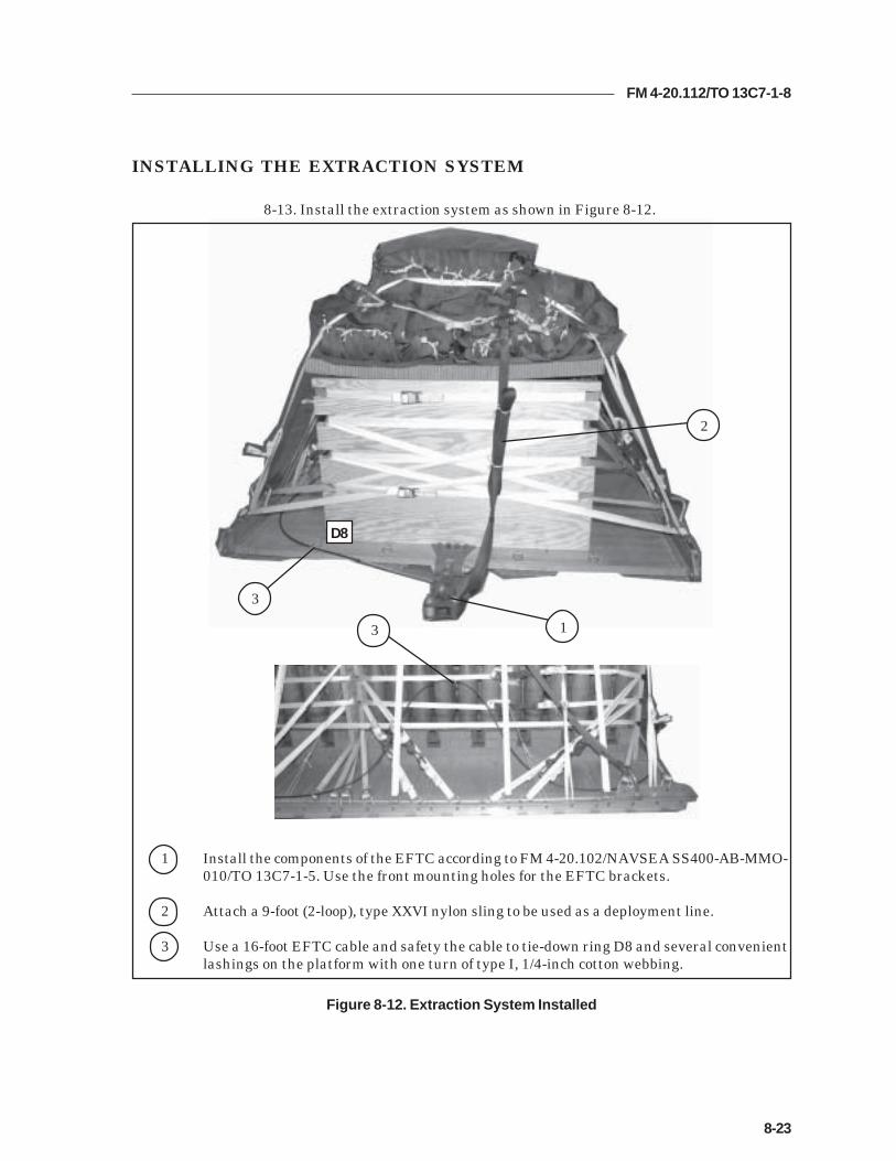
FM 4-20.112/TO 13C7-1-8
8-23
INSTALLING THE EXTRACTION SYSTEM
8-13. Install the extraction system as shown in Figure 8-12.
Figure 8-12. Extraction System Installed
1 Install the components of the EFTC according to FM 4-20.102/NAVSEA SS400-AB-MMO-010/TO 13C7-1-5. Use the front mounting holes for the EFTC brackets.
2 Attach a 9-foot (2-loop), type XXVI nylon sling to be used as a deployment line.
3 Use a 16-foot EFTC cable and safety the cable to tie-down ring D8 and several convenientlashings on the platform with one turn of type I, 1/4-inch cotton webbing.
D8
1
2
3
3

FM 4-20.112/TO 13C7-1-8
8-24
PLACING EXTRACTION PARACHUTE
8-14. Select the extraction parachute and extraction line needed using the extractionline requirements table in FM 4-20.102/ NAVSEA SS400-AB-MMO-010/TO 13C7-1-5.Place the extraction parachute and line on the load for installation in the aircraft.
INSTALLING PROVISIONS FOR EMERGENCY RESTRAINTS
8-15. Select and install the provisions for the emergency aft restraints according tothe emergency aft restraint requirements table in FM 4-20.102/NAVSEA SS400-AB-MMO-010/TO 13C7-1-5.
MARKING RIGGED LOAD
8-16. Mark the rigged load according to FM 4-20.102/NAVSEA SS400-AB-MMO-010/TO 13C7-1-5, and as shown in Figure 8-13. Complete Shipper'sDeclaration for Dangerous Goods. If the load varies from the one shown, the weight,height, CB, and parachute requirements must be recomputed.
EQUIPMENT REQUIRED
8-17. Use the equipment listed in Table 8-1 to rig this load.

FM 4-20.112/TO 13C7-1-8
8-25
RIGGED LOAD DATA
Weight..................................................................................11,460 pounds
Maximum Weight...............................................................See paragraph 8-1
Height....................................................................................48 inches
Width....................................................................................108 inches
Length..................................................................................196 inches
Overhang: Front................................................................0 inches
Rear.....................................................................0 inches
Center of Balance (CB)(from front edge of the platform)......................................96 inches
Extraction System (adds 18 inches to length of platform) EFTC
Figure 8-13. 155-MM Ammunition (MACS) Rigged on a 16-Foot, Type V Platform forLow-Velocity Airdrop
C B
CAUTIONMake the final rigger inspection required by AR 59-4 and FM 4-20.102/NAVSEASS400-AB-MMO-010/TO 13C7-1-5 before the load leaves the rigging site.

FM 4-20.112/TO 13C7-1-8
8-26
Table 8-1. Equipment Required for Rigging the 155-MM Ammunition (MACS) on a16-Foot, Type V platform for Low-Velocity Airdrop
National Stock Item Quantity Number
8040-00-273-8713 Adhesive paste, 1-gal. As required4030-00-090-5354 Clevis, suspension, 1-inch (large) 54020-00-240-2146 Cord, nylon, type III, 550-lb. As required1670-00-434-5785 Coupling, airdrop extraction force transfer, w/16-ft. cable 11670-00-360-0328 Cover, clevis 38135-00-664-6958 Cushioning material (Cellulose wadding) As required8305-00-958-3685 Felt, 1/2-inch thick As required1670-01-183-2678 Leaf, extraction line (line bag) ( add 2 for C-17) 2
Line extraction:1670-01-062-6313 60-foot (3-loop), type XXVI (for C-130) 11670-01-064-4454 60-foot (6-loop), type XXVI 11670-01-062-6312 120-foot (6-loop), type XXVI (for C-5) 11670-01-468-9178 140-foot (6-loop), type XXVI (for C-17) 11670-01-064-4452 60-foot (1-loop), type XXVI (for C-17), (drogue line) 1
Link assembly, two-point:5306-00-435-8994 Bolt, 1-inch diameter, 4-inches long (add 4 for C-5) 45310-00-232-5165 Nut, 1-inch (add 4 for C-5) 41670-00-003-1953 Plate, side, 3 3/4-inch 45365-00-007-3414 Spacer, large (add 4 for C-5) 41670-00-753-3928 Pad, energy-dissipating (honeycomb)
3- by 36- by 96-inches 13 sheets1670-01-016-7841 Parachute, cargo, G-11 3
Parachute, cargo, extraction:1670-00-063-3716 22-ft. 11670-01-063-3715 15-ft. (C-17 only) 1
Platform, airdrop, type V, 16-ft:1670-01-162-2372 Clevis assembly (type V) As required1670-01-162-2376 Extraction bracket assembly (1)1670-01-162-2381 Tandem link assembly (Multipurpose link) (4)1670-01-097-8817 Release, cargo parachute, M-1 1
Sling, cargo, airdrop:1670-01-062-6304 9-ft. (2-loop), type XXVI 11670-01-063-7761 16-ft. (2-loop), type XXVI 41670-01-062-6313 60-foot (3-loop), type XXVI 4

FM 4-20.112/TO 13C7-1-8
8-27
Table 8-1. Equipment Required for rigging the 155-MM Ammunition (MACS) on a16-Foot, Type V Platform for Low-Velocity Airdrop (Continued)
National Stock Item Quantity Number
5340-00-040-8219 Strap, parachute, release, multi-knife 27501-00-266-5016 Tape, adhesive, 2-inch As required1670-00-937-0271 Tiedown assembly, 15-ft. 521670-01-483-8259 Towplate release mechanism (H-block) (C-17 only) 1
Webbing:8305-00-268-2411 Cotton, 1/4-inch, type I As required8305-00-082-5752 Nylon, tubular, 1/2-inch As required8305-00-268-2455 Nylon, tubular, 1-inch, OD 7 As required8305-00-263-3598 Nylon, type VIII As required


FM 4-20.112/TO 13C7-1-8
Appendix -1
Appendix
INSTALLING SUSPENSION SLING SAFETY TIES
Installing the Suspension Sling Safety Ties keeps the suspension slings from making contact withthe load. The procedures in this Appendix are different from those in FM 4-20.102/NAVSEA SS400-AB-MMO-010/TO 13C7-1-5. An exception to FM 4-20.102/NAVSEA SS400-AB-MMO-010/TO 13C7-1-5 is granted. The procedures in this Appendix must be followed.Safety tie the front and rear suspension slings according to instructions shown below.
1 Cut two lengths of 1/2-inch tubular nylon webbing, making each long enough to reachfrom the left front suspension sling to the right front suspension sling plus 8 feet. Split theplies of the left front suspension sling. Route two lengths of the 1/2-inch tubular webbingthrough the plies of the sling from inboard to outboard about 3 feet.
2 Route the 3 foot running end from outboard to inboard around the inside plies andaround the outboard plies from inboard to outboard. Tie it in place on the inboard sidewith three alternating half-hitches with an overhand knot in the running end.
1
2

FM 4-20.112/TO 13C7-1-8
3 Split the plies of the right front suspension sling and route the running ends of the twolengths of 1/2-inch tubular nylon webbing through the plies of the sling from inboard tooutboard. Pass enough of the webbing through the sling to take the slack out, but notenough to keep the slings from hanging in their natural position.
4 Route the running end from outboard to inboard around the inside plies and around theoutboard plies from inboard to outboard. Tie it in place on the inboard side with threealternating half-hitches with an overhand knot in the running end.
5 Tape the webbing to the slings with masking tape.
6 Repeat steps 1 through 5 on the rear suspension slings. (not shown)
7 When using four-loop, type XXVI suspension slings, wrap each four plies with a 10-by 10-inch piece of cotton muslin. Secure each wrap with one single turn of 1/4-inch cottonwebbing. (not shown)
34
4
4
5
Appendix -2

FM 4-20.112/TO 13C7-1-8
Glossary-1
AD airdropAFB Air Force BaseAFJMAN Air Force Joint ManualAFR Air Force RegulationAFTO Air Force technical orderAR Armt Regulationattn attentionCB center of balancecap capacitychap chapterd pennyDA Department of the ArmyDC District of ColumbiaDD Department of Defensediam diameterEFTC extraction force transfer couplingFAST Foward Area Surgical TeamFM field manualHQ headquartersIAW in accordance within inchlb poundLV low-velocityMACS Modular Artillery Charge Systemmm millimeterno numberNSN national stock numberPLS palletized load systemsec secondTM technical manualTO technical orderTRADOC United States Army Training and Doctrine CommandUS United Statesw withyd yard
GLOSSARY


FM 4-20.112/TO 13C7-1-8
References-1
REFERENCES
AFMAN(I) 24-204/TM 38-250. Preparing Hazardous Materials for Military Air Shipments.14 February 2002.
AR 59-4/ OPNAVINST 4630. 24C/AFJ 13-210(I)/MCO 13480.13, Joint Airdrop Records, MalfunctionInvestigations, and Activity reporting. 1May 1998
FM 4-20.102/NAVSEA SS400-AB-MMO-010/TO 13C7-1-5. Airdrop of Supplies and Equipment:Rigging Airdrop Platforms. August 2001.
FM 4-20.153/MCRP No 4-11.B/TO 13C7-18-41. Airdrop of Supplies and Equipment: RiggingAmmunition.
FM 10-500-3/FMFM 7-47/TO 13C7-1-11, Airdrop of Supplies and Equipment: Rigging Containers.8 December 1992
TM 10-1670-278-20&P/TO 13C5-52-22, Operational Maintenance Manual Including Repair Partsand Special Tools List for Type V Platform and Dual Row Airdrop Platforms.15 September 2002
TM 10-1670-277-23&P/TO 13C5-28-2/NAVAIR 13-1-30. Unit and Direct Support (DS)Maintenance Manual Including Repair Parts and Special Tools List forParachute, Cargo Type, 28-ft Diam, Cargo Extraction. 30 April 2002.
TM 10-1670-278-23&P/TO 13C5-26-2/NAVAIR 13-1-27. Unit and IntermediateDS Maintenance Manual Including Repair Parts and SpecialTools List for Parachute, Cargo Type, 15-ft Diam, Cargo Extraction.6 November 1989.
TM 10-1670-279-23&P/TO 13C5-27-2/NAVAIR 13-1-28. Unit and Direct Support (DS)Maintenance Manual Including Repair Parts and Special Tools List forParachute, Cargo Type, 22-ft Diam, Cargo Extraction. 30 August 1989.
TM 10-1670-280-23&P/TO 13C5-31-2/NAVAIR 13-1-31. Unit and Intermediate DSMaintenance Manual Including Repair Parts and Special Tools List forParachute, Cargo Type, G-11A, G-11B, and G-11C. 15 September 2002.
TM 10-1670-286-20/TO 13C5-2-41. Unit Maintenance Manual for Sling/ExtractionLine Panel (Including Stowing Procedures). 1 April 1986.
AFTO Form 22. Technical Order Publication Improvement Report
DA Form 2028. Recommended Changes to Publication and Blank Forms. February 1974.
Shipper’s Declaration for Dangerous Goods.Locally procured form

FM 4-20.112 (FM 10-512) TO 13C7-1-8
By Order of the Secretary of the Army and the Air Force: PETER J. SCHOOMAKER General, United States Army
Chief of Staff Official:
JOEL B. HUDSON
Administrative Assistant to the Secretary of the Army 0411004 LESTER L. LYLES JOHN P. JUMPER General, USAF General, USAF Commander, AFMC Chief of Staff
DISTRIBUTION: Active Army, Army National Guard, and U.S. Army Reserve: To be distributed in accordance with the initial distribution number 110897, requirements for FM 4-20.112.
Related Documents