90894-62983-01 Worldwide Edition RIGGING GUIDE 2014

Welcome message from author
This document is posted to help you gain knowledge. Please leave a comment to let me know what you think about it! Share it to your friends and learn new things together.
Transcript

90894-62983-01Worldwide Edition
RIGGING GUIDE
2014


PREFACEThe information in this guide is based on 2014 model specification information available at the timewhen the guide has been issued.Throughout this guide, Worldwide model names are given first followed by US and Canada modelnames in parentheses for descriptive purpose.For Australia and New Zealand, US and Canada model names are used for 4-stroke 150HP andlarger models.
In this guide, particularly important information is distinguished in the following ways.
WARNINGA WARNING indicates a hazardous situation which, if not avoided, could result in death orserious injury.
NOTICEA NOTICE indicates special precautions that must be taken to avoid damage to the productsor other property.
Specifications and descriptions are subject to change without notice.The PDF file is available from the service portal site maintained by Yamaha Motor Co., Ltd.
The following contracted terms are expediently used in this guide.ASSY: assemblyDEC: Digital Electronic Remote ControlECM: Electronic Control ModuleEXT: extensionGND: ground, (–)IG: ignitionLED: light emitting diodeMGT: managementNA: not applicable, not availableOP: optionalP/N: part numberPTT: power trim & tiltPWR: powerRC: remote controlSTD: standardSTR: steeringSW: switchTBD: to be determined
© Yamaha Motor Co., Ltd.All rights reserved.Mar. 2014Produced byTechnical Publication DivisionAfter Sales SectionCS Center

CONTENTS
INSTALLATION............................................................................................1-1TOP COVER PICTOGRAPH DESCRIPTION...............................................................1-2ENGINE OIL REMINDER TAG (4-STROKE ENGINES)...............................................1-2UNCRATING PROCEDURE
(FOR TYPICAL STEEL FRAME) ..............................................................................1-3MOUNTING THE OUTBOARD MOTOR.......................................................................1-5MOUNTING THE REMOTE OIL TANK.......................................................................1-11OUTBOARD MOTOR DIMENSIONS..........................................................................1-12
PROPELLERS..............................................................................................2-1PROPELLER SPECIFICATIONS..................................................................................2-2PROPELLER SELECTION ...........................................................................................2-62014 PROPELLER APPLICATIONS ............................................................................2-6WOT OPERATION RANGE TABLE ...........................................................................2-23
REMOTE CONTROLS .................................................................................3-1REMOTE CONTROL TYPES AND APPLICATIONS....................................................3-2REMOTE SWITCH TYPES AND APPLICATIONS .....................................................3-18REMOTE CONTROL CABLES ...................................................................................3-33REMOTE CONTROL ATTACHMENT KIT ..................................................................3-35STEERING HOOK ......................................................................................................3-39STEERING GUIDE ATTACHMENT KIT .....................................................................3-42TIE-BAR KIT ...............................................................................................................3-44CONVENTIONAL WIRE HARNESS ...........................................................................3-45DIGITAL ELECTRONIC REMOTE CONTROL WIRE HARNESS ..............................3-46
TILLER HANDLES.......................................................................................4-16X4 MULTI-FUNCTION TILLER HANDLE ...................................................................4-2STEERING FRICTION CONTENTS ...........................................................................4-24
To be continued.
CONTENTS
CONVENTIONAL GAUGE (6Y5 & 6Y7) ......................................................5-1MOUNTING THE METERS ..........................................................................................5-4ANALOG TACHOMETER .............................................................................................5-5DIGITAL TACHOMETER ..............................................................................................5-7SPEEDOMETER...........................................................................................................5-9FUEL MANAGEMENT GAUGE ..................................................................................5-12ANALOG TRIM METER..............................................................................................5-18COOLANT PRESSURE METER ................................................................................5-19COOLANT TEMP. METER .........................................................................................5-20HOUR METER ............................................................................................................5-27VOLTAGE METER......................................................................................................5-29FUEL METER .............................................................................................................5-30CHARGE WARNING UNIT .........................................................................................5-31WIRE HARNESSES....................................................................................................5-32WIRING DIAGRAMS...................................................................................................5-36RIGGING GROMMET DESCRIPTION .......................................................................5-47
DIGITAL NETWORK GAUGE (6Y8) ............................................................6-1DIGITAL NETWORK GAUGE COMPATIBLE MODELS ..............................................6-2DIGITAL NETWORK GAUGE APPLICATION ..............................................................6-2DIGITAL NETWORK GAUGE DIMENSIONS ...............................................................6-3OPTIONAL EQUIPMENT..............................................................................................6-5WIRE HARNESS ..........................................................................................................6-8NETWORK HUB ...........................................................................................................6-9OPTIONAL EQUIPMENT............................................................................................6-10IMMOBILIZER UNIT ...................................................................................................6-11NETWORK WIRING DIAGRAMS ...............................................................................6-12INITIAL GAUGE SETUP .............................................................................................6-16TROUBLESHOOTING ................................................................................................6-17BASIC REQUIREMENTS ...........................................................................................6-18NMEA0183 COMPATIBLE EQUIPMENT CONNECTION ..........................................6-18DIGITAL NETWORK GAUGE (6Y8) FUNCTION TABLE ...........................................6-19
DIGITAL NETWORK PREMIUM GAUGE (6Y9) ..........................................7-1DIGITAL NETWORK PREMIUM GAUGE COMPATIBLE MODELS.............................7-3DIGITAL NETWORK PREMIUM GAUGE APPLICATION ............................................7-3DIGITAL NETWORK PREMIUM GAUGE DIMENSIONS .............................................7-4OPTIONAL EQUIPMENT..............................................................................................7-5NETWORK HUB ...........................................................................................................7-8WIRE HARNESS ..........................................................................................................7-9NETWORK WIRING DIAGRAMS ...............................................................................7-14
To be continued.
CONTENTS
BATTERY.....................................................................................................8-1RECOMMENDED BATTERY........................................................................................8-2BATTERY CABLE LENGTH .........................................................................................8-4BATTERY WIRING .......................................................................................................8-6
APPENDIX....................................................................................................9-1MODEL NAME DESIGNATION ....................................................................................9-3FUEL SYSTEM VACUUM PRESSURE STANDARD ...................................................9-5PORTABLE FUEL TANKS (TYPICAL) .........................................................................9-7FUEL PIPES (TYPICAL) ...............................................................................................9-8PRIMARY PUMP (TYPICAL) ........................................................................................9-8PRE-DELIVERY INSPECTION (PDI) ...........................................................................9-9CONVENTIONAL RIGGING KIT CONTENTS............................................................9-10DIGITAL NETWORK GAUGE RIGGING KIT CONTENTS.........................................9-13IMMOBILIZER RIGGING KIT CONTENTS.................................................................9-22DIGITAL NETWORK PREMIUM GAUGE RIGGING KIT CONTENTS.......................9-24OTHER RIGGING KIT CONTENTS............................................................................9-272014 YEAR MODELS MANUFACTURE STARTING SERIAL NUMBERS.................9-30


1-1
INSTALLATION
TOP COVER PICTOGRAPH DESCRIPTION........................................... 1-2ENGINE OIL REMINDER TAG (4-STROKE ENGINES) .......................... 1-2UNCRATING PROCEDURE
(FOR TYPICAL STEEL FRAME) ......................................................... 1-3MOUNTING THE OUTBOARD MOTOR .................................................. 1-5
WATER LEVEL GUIDELINE (4-STROKE ENGINES).......................... 1-9
ADJUSTING TWIN ENGINES............................................................ 1-10
MAX. BOAT SPEED ESTIMATION.................................................... 1-10
MOUNTING THE REMOTE OIL TANK .................................................. 1-11REMOTE OIL TANK DIMENSIONS ................................................... 1-11
NOTICE FOR MOUNTING THE REMOTE OIL TANK ....................... 1-11
OUTBOARD MOTOR DIMENSIONS ..................................................... 1-12OVERALL DIMENSION ITEMS.......................................................... 1-12
OVERALL DIMENSIONS (4-STROKE) .............................................. 1-14
OVERALL DIMENSIONS (2-STROKE) .............................................. 1-23
CLAMP BRACKET DIMENSION ITEMS............................................ 1-29
CLAMP BRACKET DIMENSIONS...................................................... 1-30

1-2
TOP COVER PICTOGRAPH DESCRIPTIONThe following pictographs are important sign to handle the crate.Read the NOTICE and understand what pictographs mean to avoid a damage to the product whenhandling, transporting and/or keeping the crate.* Photo shows F350.
ENGINE OIL REMINDER TAG (4-STROKE ENGINES)This tag is hung around the bottom cowling or the bracket to indicate that there is no engine oil inthe oil pan when the outboard motor is uncrated.
Product barycentric position
Lifting fork insert position
Stack limit: Max. 4 units for storage
Upward indication
Care handling indication
Water avoidance indication

1-3
UNCRATING PROCEDURE (FOR TYPICAL STEEL FRAME)
WARNINGWear gloves to avoid injury by sharp steeledges while uncrating.
This is an example of the steel crate for V6models.For other steel crate models, refer to this pro-cedure for uncrating the steel frame.
1. Inspect the crate for shipping damage. Ifany damage has been found, consult yourYamaha dealer.
2. Cut the strap (1).
3. Lift the top cover (2) straight up to remove.
4. Remove the bottom bolts (3).
5. Lift the top frame (4) straight up.
6. Remove the wrapping (5), and inspect theoutboard motor for concealed damage. Ifany damage is found, consult your Yamahadealer.
To be continued.
(1)
(2)
(3)
(4)
(5)
1-4
UNCRATING PROCEDURE (FOR TYPICAL STEEL FRAME)
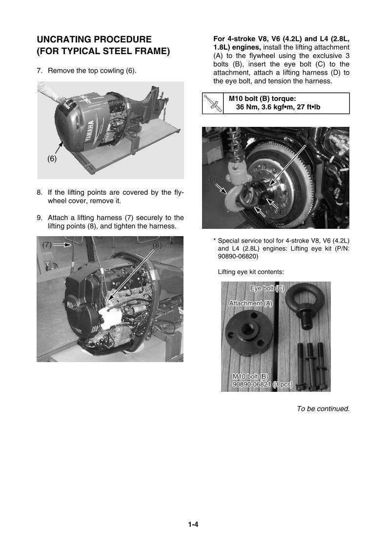
7. Remove the top cowling (6).
8. If the lifting points are covered by the fly-wheel cover, remove it.
9. Attach a lifting harness (7) securely to thelifting points (8), and tighten the harness.
For 4-stroke V8, V6 (4.2L) and L4 (2.8L,1.8L) engines, install the lifting attachment(A) to the flywheel using the exclusive 3bolts (B), insert the eye bolt (C) to theattachment, attach a lifting harness (D) tothe eye bolt, and tension the harness.
* Special service tool for 4-stroke V8, V6 (4.2L)and L4 (2.8L) engines: Lifting eye kit (P/N:90890-06820)
Lifting eye kit contents:
To be continued.
(6)
(7) (8)(7) (8)
M10 bolt (B) torque:36 Nm, 3.6 kgf•m, 27 ft•lb
(A)(A)
(D)(D)
(B)(B)(C)(C)
Eye bolt (C)Eye bolt (C)
Attachment (A)Attachment (A)
Eye bolt (C)
M10 bolt (B) M10 bolt (B) 90890-06821 (3 pcs)90890-06821 (3 pcs)M10 bolt (B) 90890-06821 (3 pcs)
Attachment (A)
1-5
UNCRATING PROCEDURE (FOR TYPICAL STEEL FRAME)
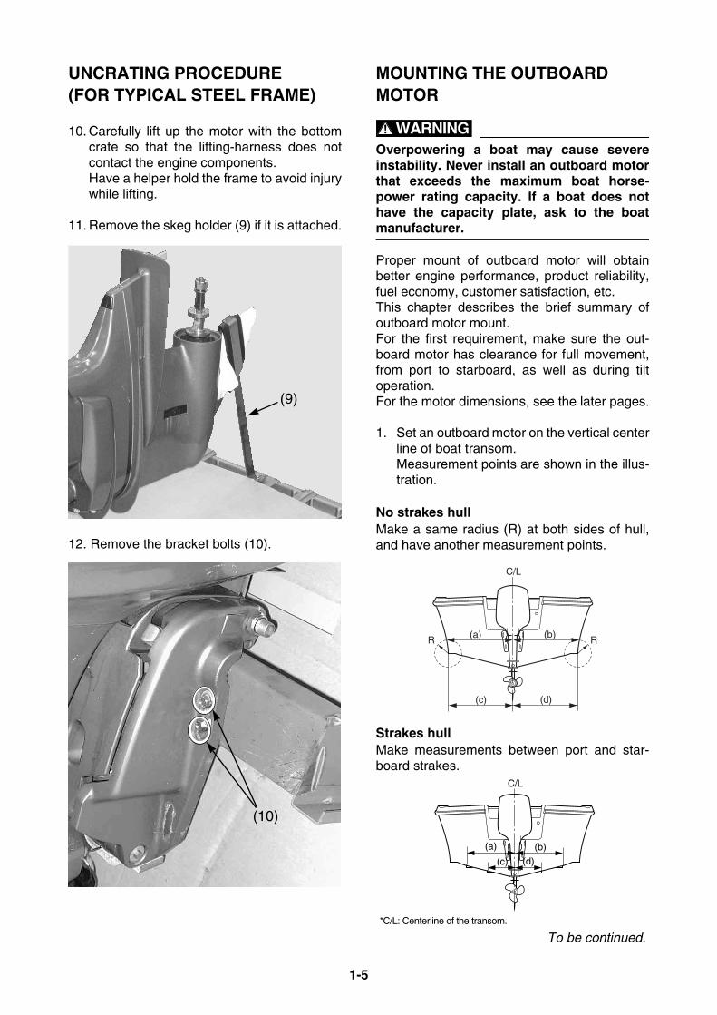
10. Carefully lift up the motor with the bottomcrate so that the lifting-harness does notcontact the engine components. Have a helper hold the frame to avoid injurywhile lifting.
11. Remove the skeg holder (9) if it is attached.
12. Remove the bracket bolts (10).
MOUNTING THE OUTBOARD MOTOR
WARNINGOverpowering a boat may cause severeinstability. Never install an outboard motorthat exceeds the maximum boat horse-power rating capacity. If a boat does nothave the capacity plate, ask to the boatmanufacturer.
Proper mount of outboard motor will obtainbetter engine performance, product reliability,fuel economy, customer satisfaction, etc.This chapter describes the brief summary ofoutboard motor mount.For the first requirement, make sure the out-board motor has clearance for full movement,from port to starboard, as well as during tiltoperation.For the motor dimensions, see the later pages.
1. Set an outboard motor on the vertical centerline of boat transom. Measurement points are shown in the illus-tration.
No strakes hullMake a same radius (R) at both sides of hull,and have another measurement points.
Strakes hullMake measurements between port and star-board strakes.
(9)
(10)
C/L
(a) (b)
(c) (d)
R R
*C/L: Centerline of the transom.
C/L
(a) (b)
(c) (d)
To be continued.
1-6
MOUNTING THE OUTBOARD MOTOR
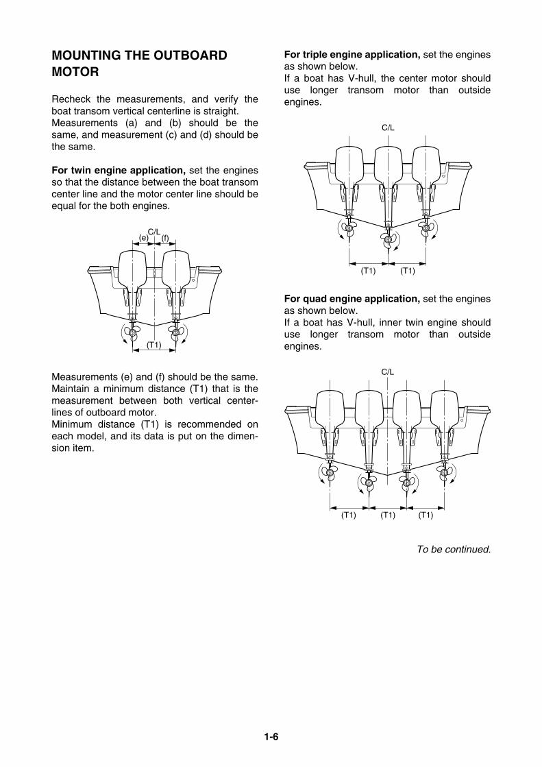
Recheck the measurements, and verify theboat transom vertical centerline is straight. Measurements (a) and (b) should be thesame, and measurement (c) and (d) should bethe same.
For twin engine application, set the enginesso that the distance between the boat transomcenter line and the motor center line should beequal for the both engines.
Measurements (e) and (f) should be the same.Maintain a minimum distance (T1) that is themeasurement between both vertical center-lines of outboard motor. Minimum distance (T1) is recommended oneach model, and its data is put on the dimen-sion item.
For triple engine application, set the enginesas shown below. If a boat has V-hull, the center motor shoulduse longer transom motor than outsideengines.
For quad engine application, set the enginesas shown below. If a boat has V-hull, inner twin engine shoulduse longer transom motor than outsideengines.
To be continued.
(T1)
C/L(e) (f)
(T1) (T1)
C/L
(T1) (T1)
C/L
(T1)

1-7
MOUNTING THE OUTBOARD MOTOR
2. Adjust the height of outboard motor so thatthe anti-cavitation plate is positioned to theboat transom bottom, or lowered within 25mm (1 in.). For planing boats, the anti-cavitation plateshould be positioned to the boat transombottom or slightly higher.
Single engine application
Twin engine application/Quad engine application
Triple engine application
* Due to combination of a boat type and an enginetype, the mount height of outboard motor varies. Therefore, the complete information is impossibleto describe here. For further information, see the instructionsissued by boat manufacturer, or ask to the manu-facturer.
3. When the outboard motor mount positionhas been determined, mark the 4 symmetri-cal mount hole positions onto the boat tran-som. Make the mount holes of 13 mm (0.5in.) vertically on the marking points.
* To make the mounting holes easier, use the drill-ing plate (P/N: 90890-06783 or YB-34465 for US).
Ex: Drilling plate (90890-06783)
To be continued.
0~25 mm (1 in.)
(a)
C/L
0~25 mm(1 in.)
(a)0~25 mm(1 in.)
Twin engine application
Quad engine application
0~25 mm(1 in.)
(a): Anti-cavitation plate
C/L
0~25 mm(1 in.)0~25 mm
(1 in.)
0~25 mm(1 in.) (a)
90
13 m
m (0
.5 in
.)
C/L
(H)
13 m
m (
0.5
in.)
(H)
(H): Motor transom heightHeight position of anti-cavitation plate
1-8
MOUNTING THE OUTBOARD MOTOR
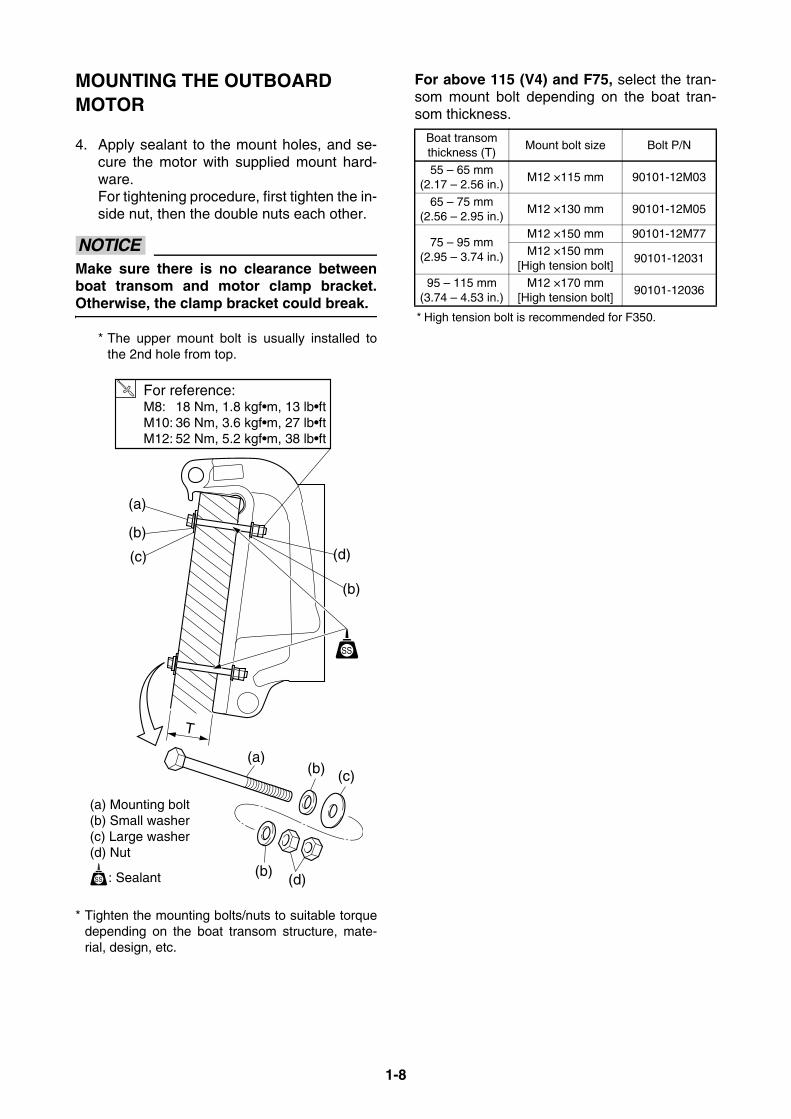
4. Apply sealant to the mount holes, and se-cure the motor with supplied mount hard-ware. For tightening procedure, first tighten the in-side nut, then the double nuts each other.
NOTICEMake sure there is no clearance betweenboat transom and motor clamp bracket.Otherwise, the clamp bracket could break.
* The upper mount bolt is usually installed tothe 2nd hole from top.
* Tighten the mounting bolts/nuts to suitable torquedepending on the boat transom structure, mate-rial, design, etc.
For above 115 (V4) and F75, select the tran-som mount bolt depending on the boat tran-som thickness.
* High tension bolt is recommended for F350.
(a)
For reference:
(a)
(b)
(b)
(d)
(d)
(b)
(b)
(c)
(c)
(a) Mounting bolt(b) Small washer(c) Large washer(d) Nut
: Sealant
T
M8: 18 Nm, 1.8 kgf•m, 13 lb•ftM10: 36 Nm, 3.6 kgf•m, 27 lb•ftM12: 52 Nm, 5.2 kgf•m, 38 lb•ft
Boat transom thickness (T)
Mount bolt size Bolt P/N
55 – 65 mm(2.17 – 2.56 in.)
M12 ×115 mm 90101-12M03
65 – 75 mm(2.56 – 2.95 in.)
M12 ×130 mm 90101-12M05
75 – 95 mm(2.95 – 3.74 in.)
M12 ×150 mm 90101-12M77M12 ×150 mm
[High tension bolt]90101-12031
95 – 115 mm(3.74 – 4.53 in.)
M12 ×170 mm [High tension bolt]
90101-12036

1-9
MOUNTING THE OUTBOARD MOTOR
WATER LEVEL GUIDELINE (4-STROKE ENGINES)If you replaced 2-stroke engine to 4-stroke engine which has the same horse power, a boat tends tobecome “stern heavy” because of heavier engine weight.As a result, water line will rise and get close to the power head.This causes poor engine performance, and water could easily enter into the cylinder(s) and damagethe engine.Therefore, you should consider the water level guideline when installing a 4-stroke outboard motor.When mooring a boat with a maximum boat load, maintain the minimum height (H) shown in theillustration between the water surface and the clamp bracket seating point.
Minimum height between water surface and bracket seating pointModel Min. height (H)
Carbureted F2 – F60 150 mm 5.9 in
Fuel injected F40 (4-cyl) – F70 100 mm 3.9 inF75 and above 100 mm 3.9 in
Water surface
(H)
1-10
MOUNTING THE OUTBOARD MOTOR
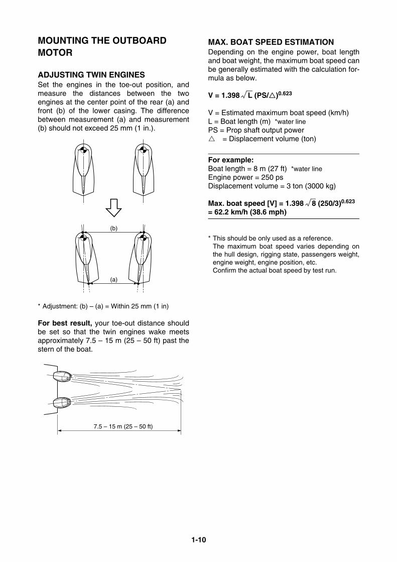
ADJUSTING TWIN ENGINESSet the engines in the toe-out position, andmeasure the distances between the twoengines at the center point of the rear (a) andfront (b) of the lower casing. The differencebetween measurement (a) and measurement(b) should not exceed 25 mm (1 in.).
* Adjustment: (b) – (a) = Within 25 mm (1 in)
For best result, your toe-out distance shouldbe set so that the twin engines wake meetsapproximately 7.5 – 15 m (25 – 50 ft) past thestern of the boat.
MAX. BOAT SPEED ESTIMATIONDepending on the engine power, boat lengthand boat weight, the maximum boat speed canbe generally estimated with the calculation for-mula as below.
V = 1.398 L (PS/)0.623
V = Estimated maximum boat speed (km/h)L = Boat length (m) *water linePS = Prop shaft output power= Displacement volume (ton)
For example:Boat length = 8 m (27 ft) *water lineEngine power = 250 psDisplacement volume = 3 ton (3000 kg)
Max. boat speed [V] = 1.398 8 (250/3)0.623
= 62.2 km/h (38.6 mph)
* This should be only used as a reference.The maximum boat speed varies depending onthe hull design, rigging state, passengers weight,engine weight, engine position, etc.Confirm the actual boat speed by test run.
(b)
(a)
7.5 – 15 m (25 – 50 ft)

1-11
MOUNTING THE REMOTE OIL TANKThe remote oil tank is required for 2-stroke V4and V6 oil injection engines.
REMOTE OIL TANK DIMENSIONS10.5 liter (2.8 US gallons) tankP/N: 6E5-21733-20
18 liter (4.8 US gallons) tankP/N: 6E5-21733-30
Oil tank holder
NOTICE FOR MOUNTING THE REMOTE OIL TANKFollow the notifications below, for the remoteoil tank installation.• Mount the oil tank in as dry as possible loca-
tion to avoid water entering into the oil tank.• Mount in a location that will allow service to
the filter located on the remote oil tank.• Mount the remote oil tank lower than the
engine oil tank. If the remote oil tank is mounted higher thanthe top of the engine because of the boattype, an optional check valve (P/N: 6R5-24408-00) shown below is required.
Install the check valve on the oil hosebetween the engine and remote oil tank toprevent siphoning of oil to the engine andspillage.
• Route the oil hose between the engine andthe remote oil tank without pinching andkinking.
320 (12.6)18
0 (7
.1)
230
(9.1
)mm (in.)
180
(7.1
)
508 (20)
235
(9.3
)
mm (in.)
250 (9.8)
200 (7.9)
170 (6.7)
6.5 (0.26)
40 (1.6)
200 (7.9)
25 (1.0)
112(4.4)
30(1.2)173(6.8)
210 (8.3)
160 (6.3)130 (5.1)
30
(1.2)
mm (in.)
1-12
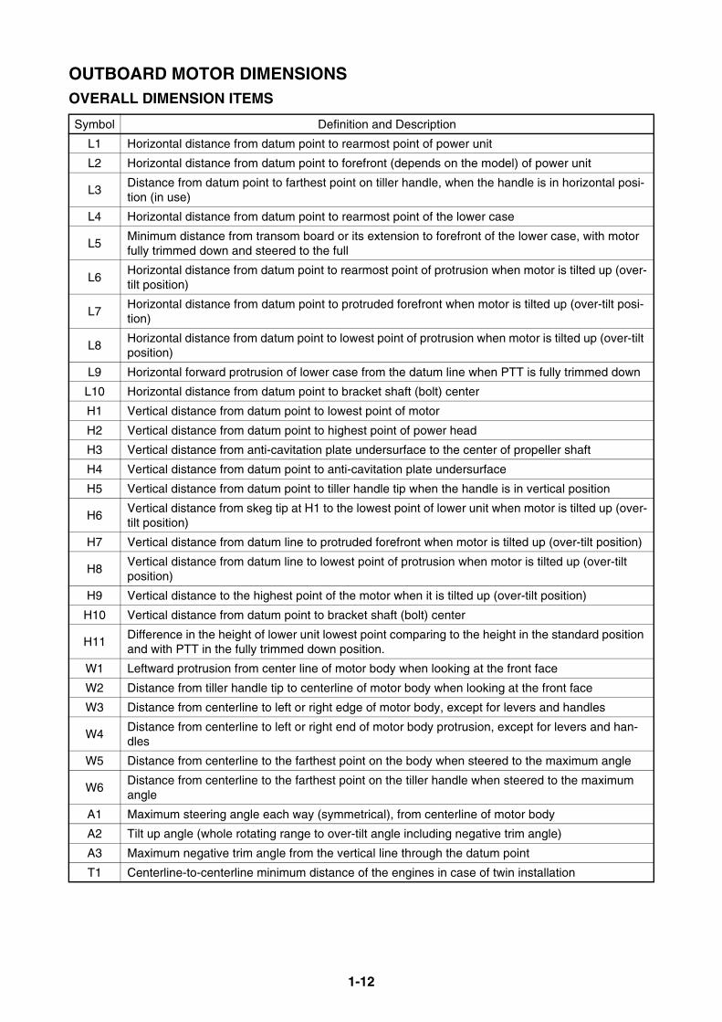
OUTBOARD MOTOR DIMENSIONSOVERALL DIMENSION ITEMS
Symbol Definition and Description
L1 Horizontal distance from datum point to rearmost point of power unit
L2 Horizontal distance from datum point to forefront (depends on the model) of power unit
L3Distance from datum point to farthest point on tiller handle, when the handle is in horizontal posi-tion (in use)
L4 Horizontal distance from datum point to rearmost point of the lower case
L5Minimum distance from transom board or its extension to forefront of the lower case, with motor fully trimmed down and steered to the full
L6Horizontal distance from datum point to rearmost point of protrusion when motor is tilted up (over-tilt position)
L7Horizontal distance from datum point to protruded forefront when motor is tilted up (over-tilt posi-tion)
L8Horizontal distance from datum point to lowest point of protrusion when motor is tilted up (over-tilt position)
L9 Horizontal forward protrusion of lower case from the datum line when PTT is fully trimmed down
L10 Horizontal distance from datum point to bracket shaft (bolt) center
H1 Vertical distance from datum point to lowest point of motor
H2 Vertical distance from datum point to highest point of power head
H3 Vertical distance from anti-cavitation plate undersurface to the center of propeller shaft
H4 Vertical distance from datum point to anti-cavitation plate undersurface
H5 Vertical distance from datum point to tiller handle tip when the handle is in vertical position
H6Vertical distance from skeg tip at H1 to the lowest point of lower unit when motor is tilted up (over-tilt position)
H7 Vertical distance from datum line to protruded forefront when motor is tilted up (over-tilt position)
H8Vertical distance from datum line to lowest point of protrusion when motor is tilted up (over-tilt position)
H9 Vertical distance to the highest point of the motor when it is tilted up (over-tilt position)
H10 Vertical distance from datum point to bracket shaft (bolt) center
H11Difference in the height of lower unit lowest point comparing to the height in the standard position and with PTT in the fully trimmed down position.
W1 Leftward protrusion from center line of motor body when looking at the front face
W2 Distance from tiller handle tip to centerline of motor body when looking at the front face
W3 Distance from centerline to left or right edge of motor body, except for levers and handles
W4Distance from centerline to left or right end of motor body protrusion, except for levers and han-dles
W5 Distance from centerline to the farthest point on the body when steered to the maximum angle
W6Distance from centerline to the farthest point on the tiller handle when steered to the maximum angle
A1 Maximum steering angle each way (symmetrical), from centerline of motor body
A2 Tilt up angle (whole rotating range to over-tilt angle including negative trim angle)
A3 Maximum negative trim angle from the vertical line through the datum point
T1 Centerline-to-centerline minimum distance of the engines in case of twin installation
1-13
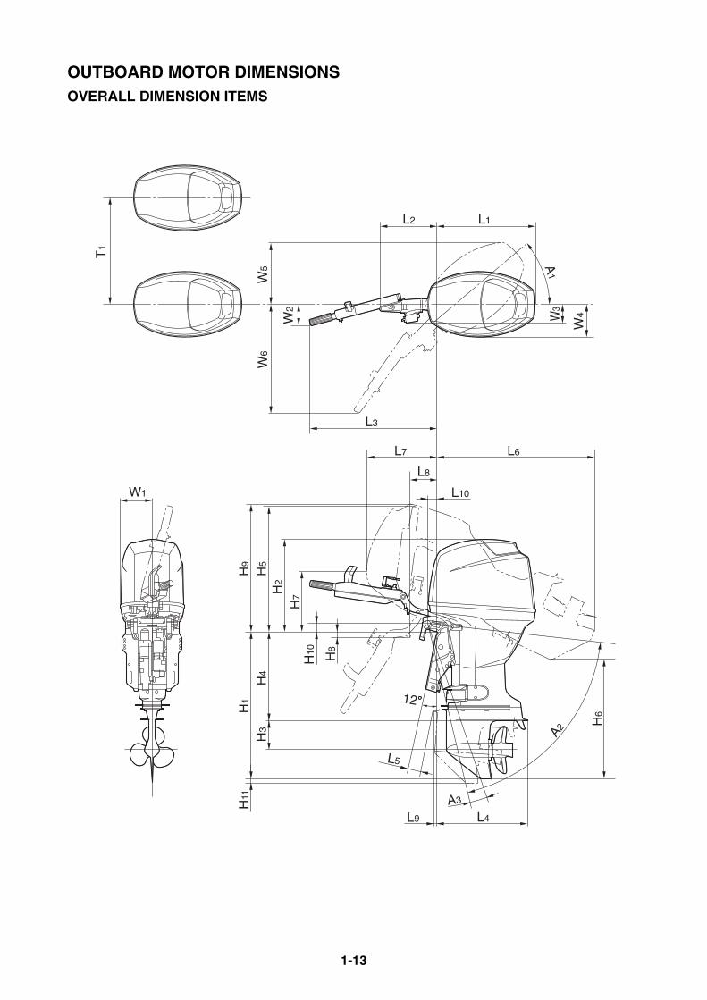
OUTBOARD MOTOR DIMENSIONSOVERALL DIMENSION ITEMS
L4
A3
H6
L6L7
L3
L2 L1
W3
W4
A1
W5
W6
W2
W1
H10 H8
H7
H2
H5
H4
H3
H11
H9
H1
L10
L8
L5
12
A2
T1
L9
1-14
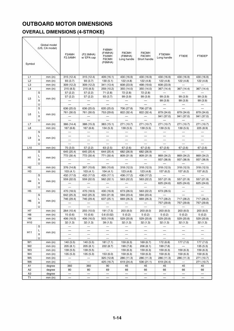
OUTBOARD MOTOR DIMENSIONSOVERALL DIMENSIONS (4-STROKE)
Global model(US, CA model)
Symbol
F2AMHF2.5AMH
(F2.5MHA)w/ EPA cap
F4BMH(F4MHA)F5AMHF6CMH
(F6MHA)
F8CMH(F8MHA)
Long handle
F8CMHF8CWH
Short handle
FT8DMHLong handle
FT8DE FT8DEP
L1 mm (in) 315 (12.4) 315 (12.4) 409 (16.1) 430 (16.9) 430 (16.9) 430 (16.9) 430 (16.9) 430 (16.9)L2 mm (in) 93 (3.7) 93 (3.7) 130 (5.1) 122 (4.8) 122 (4.8) 122 (4.8) 122 (4.8) 122 (4.8)L3 mm (in) 309 (12.2) 309 (12.2) 341 (13.4) 608 (23.9) 498 (19.6) 608 (23.9) — —L4 mm (in) 215 (8.5) 215 (8.5) 259 (10.2) 355 (14.0) 355 (14.0) 367 (14.4) 367 (14.4) 367 (14.4)
L5
S
mm (in)
57 (2.2) 57 (2.2) 71 (2.8) 72 (2.8) 72 (2.8) — — —L 57 (2.2) 57 (2.2) 93 (3.7) 99 (3.9) 99 (3.9) 99 (3.9) 99 (3.9) 99 (3.9)X — — — — — 99 (3.9) 99 (3.9) 99 (3.9)U — — — — — — — —
L6
S
mm (in)
636 (25.0) 636 (25.0) 635 (25.0) 706 (27.8) 706 (27.8) — — —L 761 (30.0) 761 (30.0) 753 (29.6) 822 (32.4) 822 (32.4) 879 (34.6) 879 (34.6) 879 (34.6)X — — — — — 941 (37.0) 941 (37.0) 941 (37.0)U — — — — — — — —
L7 mm (in) 366 (14.4) 388 (15.3) 383 (15.1) 271 (10.7) 271 (10.7) 271 (10.7) 271 (10.7) 271 (10.7)L8 mm (in) 167 (6.6) 167 (6.6) 134 (5.3) 139 (5.5) 139 (5.5) 139 (5.5) 139 (5.5) 225 (8.9)
L9
S
mm (in)
— — — — — — — —L — — — — — — — —X — — — — — — — —U — — — — — — — —
L10 mm (in) 75 (3.0) 57 (2.2) 63 (2.5) 67 (2.6) 67 (2.6) 67 (2.6) 67 (2.6) 67 (2.6)
H1
S
mm (in)
645 (25.4) 645 (25.4) 644 (25.4) 682 (26.9) 682 (26.9) — — —L 772 (30.4) 772 (30.4) 771 (30.4) 809 (31.9) 809 (31.9) 869 (34.2) 869 (34.2) 869 (34.2)X — — — — — 937 (36.9) 937 (36.9) 937 (36.9)U — — — — — — — —
H2 mm (in) 376 (14.8) 397 (15.6) 395 (15.6) 318 (12.5) 318 (12.5) 318 (12.5) 318 (12.5) 318 (12.5)H3 mm (in) 103 (4.1) 103 (4.1) 104 (4.1) 123 (4.8) 123 (4.8) 157 (6.2) 157 (6.2) 157 (6.2)
H4
S
mm (in)
432 (17.0) 432 (17.0) 435 (17.1) 436 (17.2) 436 (17.2) — — —L 559 (22.0) 559 (22.0) 562 (22.1) 563 (22.2) 563 (22.2) 557 (21.9) 557 (21.9) 557 (21.9)X — — — — — 625 (24.6) 625 (24.6) 625 (24.6)U — — — — — — — —
H5 mm (in) 470 (18.5) 470 (18.5) 430 (16.9) 673 (26.5) 563 (22.2) 673 (26.5) — —
H6
S
mm (in)
642 (25.3) 642 (25.3) 555 (21.9) 594 (23.4) 594 (23.4) — — —L 746 (29.4) 746 (29.4) 637 (25.1) 669 (26.3) 669 (26.3) 717 (28.2) 717 (28.2) 717 (28.2)X — — — — — 757 (29.8) 757 (29.8) 757 (29.8)U — — — — — — — —
H7 mm (in) 264 (10.4) 255 (10.0) 191 (7.5) 203 (8.0) 203 (8.0) 203 (8.0) 203 (8.0) 203 (8.0)H8 mm (in) 15 (0.6) 15 (0.6) 0.6 (0.02) 5 (0.2) 5 (0.2) 5 (0.2) 5 (0.2) 5 (0.2)H9 mm (in) 406 (16.0) 406 (16.0) 503 (19.8) 529 (20.8) 529 (20.8) 529 (20.8) 529 (20.8) 529 (20.8)
H10 mm (in) 32 (1.3) 32 (1.3) 39 (1.5) 32 (1.3) 32 (1.3) 32 (1.3) 32 (1.3) 32 (1.3)
H11
S
mm (in)
— — — — — — — —L — — — — — — — —X — — — — — — — —U — — — — — — — —
W1 mm (in) 140 (5.5) 140 (5.5) 181 (7.1) 159 (6.3) 169 (6.7) 172 (6.8) 177 (7.0) 177 (7.0)W2 mm (in) 205 (8.1) 205 (8.1) 222 (8.7) 199 (7.8) 206 (8.1) 199 (7.8) — 135 (5.3)W3 mm (in) 139 (5.5) 139 (5.5) — 159 (6.3) 159 (6.3) 159 (6.3) 159 (6.3) 159 (6.3)W4 mm (in) 135 (5.3) 135 (5.3) 153 (6.0) 159 (6.3) 159 (6.3) 159 (6.3) 159 (6.3) 159 (6.3)W5 mm (in) — — 325 (12.8) 286 (11.3) 286 (11.3) 286 (11.3) 286 (11.3) 271 (10.7)W6 mm (in) — — 425 (16.7) 619 (24.4) 536 (21.1) 619 (24.4) — 271 (10.7)A1 degree 360 360 90 45 45 45 45 40A2 degree 80 80 69 66 66 66 66 66A3 degree — — — — — — — —T1 mm (in) — — — — — — — —
1-15
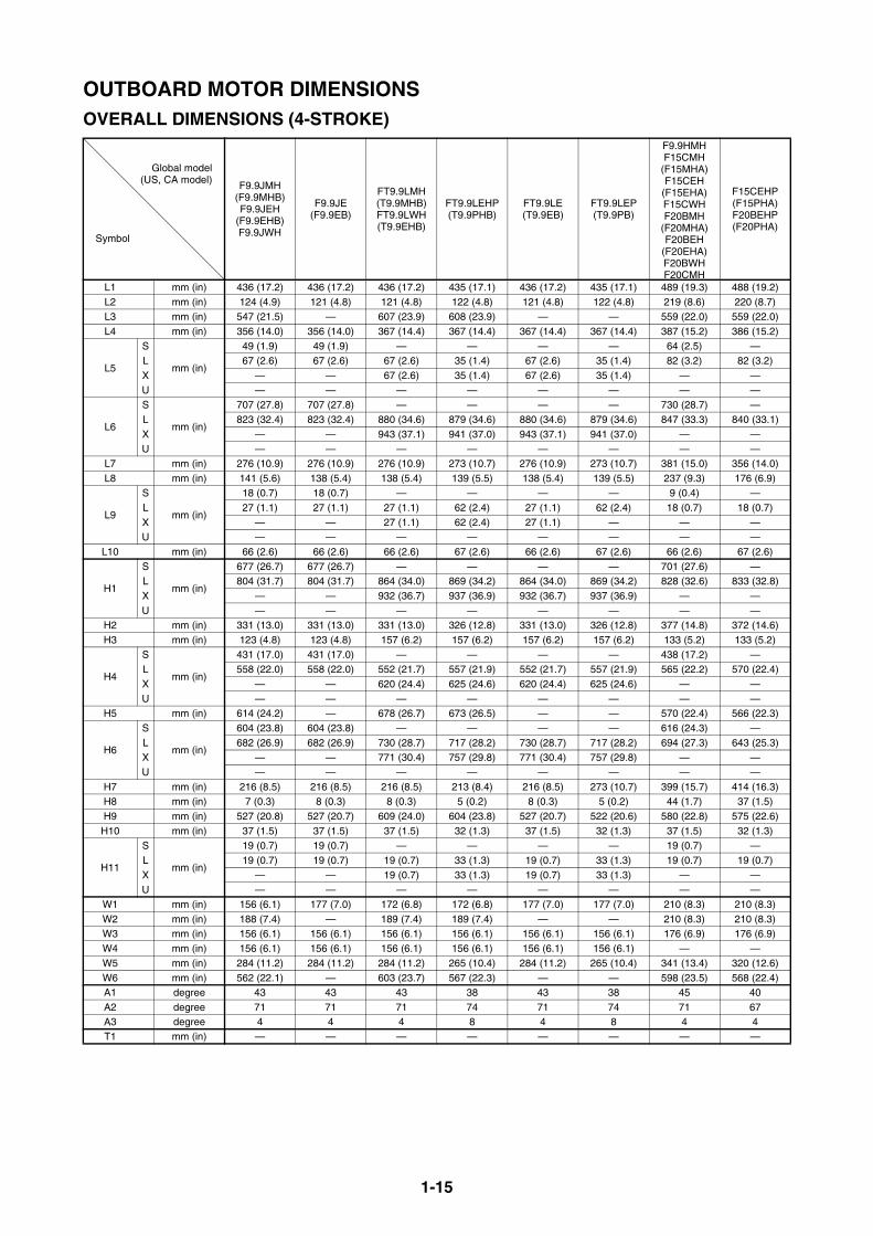
OUTBOARD MOTOR DIMENSIONSOVERALL DIMENSIONS (4-STROKE)
Global model(US, CA model)
Symbol
F9.9JMH(F9.9MHB)F9.9JEH
(F9.9EHB)F9.9JWH
F9.9JE(F9.9EB)
FT9.9LMH(T9.9MHB)FT9.9LWH(T9.9EHB)
FT9.9LEHP(T9.9PHB)
FT9.9LE(T9.9EB)
FT9.9LEP(T9.9PB)
F9.9HMHF15CMH
(F15MHA)F15CEH
(F15EHA)F15CWHF20BMH
(F20MHA)F20BEH
(F20EHA)F20BWHF20CMH
F15CEHP(F15PHA)F20BEHP(F20PHA)
L1 mm (in) 436 (17.2) 436 (17.2) 436 (17.2) 435 (17.1) 436 (17.2) 435 (17.1) 489 (19.3) 488 (19.2)L2 mm (in) 124 (4.9) 121 (4.8) 121 (4.8) 122 (4.8) 121 (4.8) 122 (4.8) 219 (8.6) 220 (8.7)L3 mm (in) 547 (21.5) — 607 (23.9) 608 (23.9) — — 559 (22.0) 559 (22.0)L4 mm (in) 356 (14.0) 356 (14.0) 367 (14.4) 367 (14.4) 367 (14.4) 367 (14.4) 387 (15.2) 386 (15.2)
L5
S
mm (in)
49 (1.9) 49 (1.9) — — — — 64 (2.5) —L 67 (2.6) 67 (2.6) 67 (2.6) 35 (1.4) 67 (2.6) 35 (1.4) 82 (3.2) 82 (3.2)X — — 67 (2.6) 35 (1.4) 67 (2.6) 35 (1.4) — —U — — — — — — — —
L6
S
mm (in)
707 (27.8) 707 (27.8) — — — — 730 (28.7) —L 823 (32.4) 823 (32.4) 880 (34.6) 879 (34.6) 880 (34.6) 879 (34.6) 847 (33.3) 840 (33.1)X — — 943 (37.1) 941 (37.0) 943 (37.1) 941 (37.0) — —U — — — — — — — —
L7 mm (in) 276 (10.9) 276 (10.9) 276 (10.9) 273 (10.7) 276 (10.9) 273 (10.7) 381 (15.0) 356 (14.0)L8 mm (in) 141 (5.6) 138 (5.4) 138 (5.4) 139 (5.5) 138 (5.4) 139 (5.5) 237 (9.3) 176 (6.9)
L9
S
mm (in)
18 (0.7) 18 (0.7) — — — — 9 (0.4) —L 27 (1.1) 27 (1.1) 27 (1.1) 62 (2.4) 27 (1.1) 62 (2.4) 18 (0.7) 18 (0.7)X — — 27 (1.1) 62 (2.4) 27 (1.1) — — —U — — — — — — — —
L10 mm (in) 66 (2.6) 66 (2.6) 66 (2.6) 67 (2.6) 66 (2.6) 67 (2.6) 66 (2.6) 67 (2.6)
H1
S
mm (in)
677 (26.7) 677 (26.7) — — — — 701 (27.6) —L 804 (31.7) 804 (31.7) 864 (34.0) 869 (34.2) 864 (34.0) 869 (34.2) 828 (32.6) 833 (32.8)X — — 932 (36.7) 937 (36.9) 932 (36.7) 937 (36.9) — —U — — — — — — — —
H2 mm (in) 331 (13.0) 331 (13.0) 331 (13.0) 326 (12.8) 331 (13.0) 326 (12.8) 377 (14.8) 372 (14.6)H3 mm (in) 123 (4.8) 123 (4.8) 157 (6.2) 157 (6.2) 157 (6.2) 157 (6.2) 133 (5.2) 133 (5.2)
H4
S
mm (in)
431 (17.0) 431 (17.0) — — — — 438 (17.2) —L 558 (22.0) 558 (22.0) 552 (21.7) 557 (21.9) 552 (21.7) 557 (21.9) 565 (22.2) 570 (22.4)X — — 620 (24.4) 625 (24.6) 620 (24.4) 625 (24.6) — —U — — — — — — — —
H5 mm (in) 614 (24.2) — 678 (26.7) 673 (26.5) — — 570 (22.4) 566 (22.3)
H6
S
mm (in)
604 (23.8) 604 (23.8) — — — — 616 (24.3) —L 682 (26.9) 682 (26.9) 730 (28.7) 717 (28.2) 730 (28.7) 717 (28.2) 694 (27.3) 643 (25.3)X — — 771 (30.4) 757 (29.8) 771 (30.4) 757 (29.8) — —U — — — — — — — —
H7 mm (in) 216 (8.5) 216 (8.5) 216 (8.5) 213 (8.4) 216 (8.5) 273 (10.7) 399 (15.7) 414 (16.3)H8 mm (in) 7 (0.3) 8 (0.3) 8 (0.3) 5 (0.2) 8 (0.3) 5 (0.2) 44 (1.7) 37 (1.5)H9 mm (in) 527 (20.8) 527 (20.7) 609 (24.0) 604 (23.8) 527 (20.7) 522 (20.6) 580 (22.8) 575 (22.6)
H10 mm (in) 37 (1.5) 37 (1.5) 37 (1.5) 32 (1.3) 37 (1.5) 32 (1.3) 37 (1.5) 32 (1.3)
H11
S
mm (in)
19 (0.7) 19 (0.7) — — — — 19 (0.7) —L 19 (0.7) 19 (0.7) 19 (0.7) 33 (1.3) 19 (0.7) 33 (1.3) 19 (0.7) 19 (0.7)X — — 19 (0.7) 33 (1.3) 19 (0.7) 33 (1.3) — —U — — — — — — — —
W1 mm (in) 156 (6.1) 177 (7.0) 172 (6.8) 172 (6.8) 177 (7.0) 177 (7.0) 210 (8.3) 210 (8.3)W2 mm (in) 188 (7.4) — 189 (7.4) 189 (7.4) — — 210 (8.3) 210 (8.3)W3 mm (in) 156 (6.1) 156 (6.1) 156 (6.1) 156 (6.1) 156 (6.1) 156 (6.1) 176 (6.9) 176 (6.9)W4 mm (in) 156 (6.1) 156 (6.1) 156 (6.1) 156 (6.1) 156 (6.1) 156 (6.1) — —W5 mm (in) 284 (11.2) 284 (11.2) 284 (11.2) 265 (10.4) 284 (11.2) 265 (10.4) 341 (13.4) 320 (12.6)W6 mm (in) 562 (22.1) — 603 (23.7) 567 (22.3) — — 598 (23.5) 568 (22.4)A1 degree 43 43 43 38 43 38 45 40A2 degree 71 71 71 74 71 74 71 67A3 degree 4 4 4 8 4 8 4 4T1 mm (in) — — — — — — — —
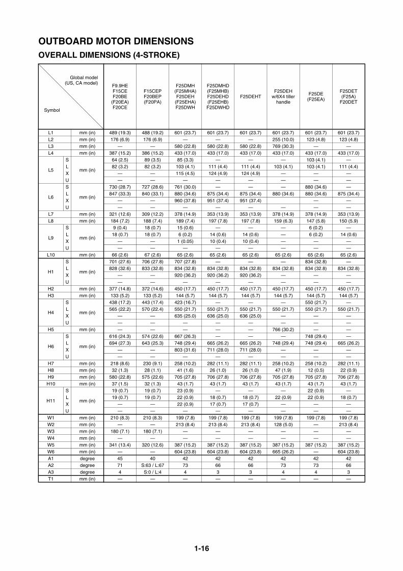
1-16
OUTBOARD MOTOR DIMENSIONSOVERALL DIMENSIONS (4-STROKE)
Global model(US, CA model)
Symbol
F9.9HEF15CEF20BE
(F20EA)F20CE
F15CEPF20BEP(F20PA)
F25DMH(F25MHA)F25DEH
(F25EHA)F25DWH
F25DMHD(F25MHB)F25DEHD(F25EHB)F25DWHD
F25DEHTF25DEH
w/6X4 tiller handle
F25DE(F25EA)
F25DET(F25A)
F20DET
L1 mm (in) 489 (19.3) 488 (19.2) 601 (23.7) 601 (23.7) 601 (23.7) 601 (23.7) 601 (23.7) 601 (23.7)L2 mm (in) 176 (6.9) 176 (6.9) — — — 255 (10.0) 123 (4.8) 123 (4.8)L3 mm (in) — — 580 (22.8) 580 (22.8) 580 (22.8) 769 (30.3) — —L4 mm (in) 387 (15.2) 386 (15.2) 433 (17.0) 433 (17.0) 433 (17.0) 433 (17.0) 433 (17.0) 433 (17.0)
L5
S
mm (in)
64 (2.5) 89 (3.5) 85 (3.3) — — — 103 (4.1) —L 82 (3.2) 82 (3.2) 103 (4.1) 111 (4.4) 111 (4.4) 103 (4.1) 103 (4.1) 111 (4.4)X — — 115 (4.5) 124 (4.9) 124 (4.9) — — —U — — — — — — — —
L6
S
mm (in)
730 (28.7) 727 (28.6) 761 (30.0) — — — 880 (34.6) —L 847 (33.3) 840 (33.1) 880 (34.6) 875 (34.4) 875 (34.4) 880 (34.6) 880 (34.6) 875 (34.4)X — — 960 (37.8) 951 (37.4) 951 (37.4) — —U — — — — — — — —
L7 mm (in) 321 (12.6) 309 (12.2) 378 (14.9) 353 (13.9) 353 (13.9) 378 (14.9) 378 (14.9) 353 (13.9)L8 mm (in) 184 (7.2) 188 (7.4) 189 (7.4) 197 (7.8) 197 (7.8) 159 (6.3) 147 (5.8) 150 (5.9)
L9
S
mm (in)
9 (0.4) 18 (0.7) 15 (0.6) — — — 6 (0.2) —L 18 (0.7) 18 (0.7) 6 (0.2) 14 (0.6) 14 (0.6) — 6 (0.2) 14 (0.6)X — — 1 (0.05) 10 (0.4) 10 (0.4) — — —U — — — — — — — —
L10 mm (in) 66 (2.6) 67 (2.6) 65 (2.6) 65 (2.6) 65 (2.6) 65 (2.6) 65 (2.6) 65 (2.6)
H1
S
mm (in)
701 (27.6) 706 (27.8) 707 (27.8) — — — 834 (32.8) —L 828 (32.6) 833 (32.8) 834 (32.8) 834 (32.8) 834 (32.8) 834 (32.8) 834 (32.8) 834 (32.8)X — — 920 (36.2) 920 (36.2) 920 (36.2) — — —U — — — — — — — —
H2 mm (in) 377 (14.8) 372 (14.6) 450 (17.7) 450 (17.7) 450 (17.7) 450 (17.7) 450 (17.7) 450 (17.7)H3 mm (in) 133 (5.2) 133 (5.2) 144 (5.7) 144 (5.7) 144 (5.7) 144 (5.7) 144 (5.7) 144 (5.7)
H4
S
mm (in)
438 (17.2) 443 (17.4) 423 (16.7) — — — 550 (21.7) —L 565 (22.2) 570 (22.4) 550 (21.7) 550 (21.7) 550 (21.7) 550 (21.7) 550 (21.7) 550 (21.7)X — — 635 (25.0) 636 (25.0) 636 (25.0) — — —U — — — — — — — —
H5 mm (in) — — — — — 766 (30.2) — —
H6
S
mm (in)
616 (24.3) 574 (22.6) 667 (26.3) — — — 748 (29.4) —L 694 (27.3) 643 (25.3) 748 (29.4) 665 (26.2) 665 (26.2) 748 (29.4) 748 (29.4) 665 (26.2)X — — 803 (31.6) 711 (28.0) 711 (28.0) — — —U — — — — — — — —
H7 mm (in) 218 (8.6) 230 (9.1) 258 (10.2) 282 (11.1) 282 (11.1) 258 (10.2) 258 (10.2) 282 (11.1)H8 mm (in) 32 (1.3) 28 (1.1) 41 (1.6) 26 (1.0) 26 (1.0) 47 (1.9) 12 (0.5) 22 (0.9)H9 mm (in) 580 (22.8) 575 (22.6) 705 (27.8) 706 (27.8) 706 (27.8) 705 (27.8) 705 (27.8) 706 (27.8)
H10 mm (in) 37 (1.5) 32 (1.3) 43 (1.7) 43 (1.7) 43 (1.7) 43 (1.7) 43 (1.7) 43 (1.7)
H11
S
mm (in)
19 (0.7) 19 (0.7) 23 (0.9) — — — 22 (0.9) —L 19 (0.7) 19 (0.7) 22 (0.9) 18 (0.7) 18 (0.7) 22 (0.9) 22 (0.9) 18 (0.7)X — — 22 (0.9) 17 (0.7) 17 (0.7) — — —U — — — — — — — —
W1 mm (in) 210 (8.3) 210 (8.3) 199 (7.8) 199 (7.8) 199 (7.8) 199 (7.8) 199 (7.8) 199 (7.8)W2 mm (in) — — 213 (8.4) 213 (8.4) 213 (8.4) 128 (5.0) — 213 (8.4)W3 mm (in) 180 (7.1) 180 (7.1) — — — — — —W4 mm (in) — — — — — — — —W5 mm (in) 341 (13.4) 320 (12.6) 387 (15.2) 387 (15.2) 387 (15.2) 387 (15.2) 387 (15.2) 387 (15.2)W6 mm (in) — — 604 (23.8) 604 (23.8) 604 (23.8) 665 (26.2) — 604 (23.8)A1 degree 45 40 42 42 42 42 42 42 A2 degree 71 S:63 / L:67 73 66 66 73 73 66 A3 degree 4 S:0 / L:4 4 3 3 4 4 3T1 mm (in) — — — — — — — —
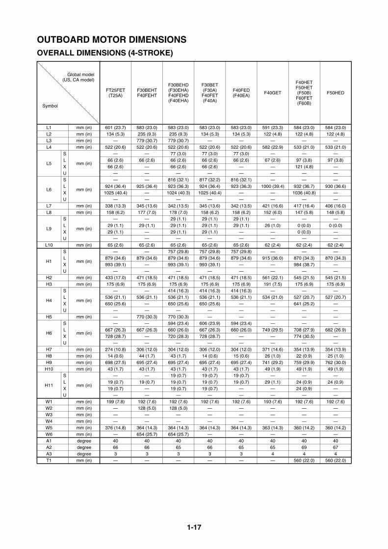
1-17
OUTBOARD MOTOR DIMENSIONSOVERALL DIMENSIONS (4-STROKE)
Global model(US, CA model)
Symbol
FT25FET(T25A)
F30BEHTF40FEHT
F30BEHD(F30EHA)F40FEHD(F40EHA)
F30BET(F30A)
F40FET(F40A)
F40FED(F40EA)
F40GET
F40HETF50HET(F50B)F60FET(F60B)
F50HED
L1 mm (in) 601 (23.7) 583 (23.0) 583 (23.0) 583 (23.0) 583 (23.0) 591 (23.3) 584 (23.0) 584 (23.0)L2 mm (in) 134 (5.3) 235 (9.3) 235 (9.3) 134 (5.3) 134 (5.3) 122 (4.8) 122 (4.8) 122 (4.8)L3 mm (in) — 779 (30.7) 779 (30.7) — — — — —L4 mm (in) 522 (20.6) 522 (20.6) 522 (20.6) 522 (20.6) 522 (20.6) 582 (22.9) 533 (21.0) 533 (21.0)
L5
S
mm (in)
— — 77 (3.0) 77 (3.0) 77 (3.0) — — —L 66 (2.6) 66 (2.6) 66 (2.6) 66 (2.6) 66 (2.6) 67 (2.6) 97 (3.8) 97 (3.8)X 66 (2.6) — 66 (2.6) 66 (2.6) — — 121 (4.8) —U — — — — — — — —
L6
S
mm (in)
— — 816 (32.1) 817 (32.2) 816 (32.1) — — —L 924 (36.4) 925 (36.4) 923 (36.3) 924 (36.4) 923 (36.3) 1000 (39.4) 932 (36.7) 930 (36.6)X 1025 (40.4) — 1024 (40.3) 1025 (40.4) — — 1036 (40.8) —U — — — — — — — —
L7 mm (in) 338 (13.3) 345 (13.6) 342 (13.5) 345 (13.6) 342 (13.5) 421 (16.6) 417 (16.4) 406 (16.0)L8 mm (in) 158 (6.2) 177 (7.0) 178 (7.0) 158 (6.2) 158 (6.2) 152 (6.0) 147 (5.8) 148 (5.8)
L9
S
mm (in)
— — 29 (1.1) 29 (1.1) 29 (1.1) — — —L 29 (1.1) 29 (1.1) 29 (1.1) 29 (1.1) 29 (1.1) 26 (1.0) 0 (0.0) 0 (0.0)X 29 (1.1) — 29 (1.1) 29 (1.1) — — 0 (0.0) —U — — — — — — — —
L10 mm (in) 65 (2.6) 65 (2.6) 65 (2.6) 65 (2.6) 65 (2.6) 62 (2.4) 62 (2.4) 62 (2.4)
H1
S
mm (in)
— — 757 (29.8) 757 (29.8) 757 (29.8) — — —L 879 (34.6) 879 (34.6) 879 (34.6) 879 (34.6) 879 (34.6) 915 (36.0) 870 (34.3) 870 (34.3)X 993 (39.1) — 993 (39.1) 993 (39.1) — — 984 (38.7) —U — — — — — — — —
H2 mm (in) 433 (17.0) 471 (18.5) 471 (18.5) 471 (18.5) 471 (18.5) 561 (22.1) 545 (21.5) 545 (21.5)H3 mm (in) 175 (6.9) 175 (6.9) 175 (6.9) 175 (6.9) 175 (6.9) 191 (7.5) 175 (6.9) 175 (6.9)
H4
S
mm (in)
— — 414 (16.3) 414 (16.3) 414 (16.3) — — —L 536 (21.1) 536 (21.1) 536 (21.1) 536 (21.1) 536 (21.1) 534 (21.0) 527 (20.7) 527 (20.7)X 650 (25.6) — 650 (25.6) 650 (25.6) — — 641 (25.2) —U — — — — — — — —
H5 mm (in) — 770 (30.3) 770 (30.3) — — — — —
H6
S
mm (in)
— — 594 (23.4) 606 (23.9) 594 (23.4) — — —L 667 (26.3) 667 (26.3) 660 (26.0) 667 (26.3) 660 (26.0) 749 (29.5) 708 (27.9) 682 (26.9)X 728 (28.7) — 720 (28.3) 728 (28.7) — — 774 (30.5) —U — — — — — — — —
H7 mm (in) 274 (10.8) 306 (12.0) 304 (12.0) 306 (12.0) 304 (12.0) 371 (14.6) 354 (13.9) 354 (13.9)H8 mm (in) 14 (0.6) 44 (1.7) 43 (1.7) 14 (0.6) 15 (0.6) 26 (1.0) 22 (0.9) 25 (1.0)H9 mm (in) 698 (27.5) 695 (27.4) 695 (27.4) 695 (27.4) 695 (27.4) 741 (29.2) 759 (29.9) 762 (30.0)
H10 mm (in) 43 (1.7) 43 (1.7) 43 (1.7) 43 (1.7) 43 (1.7) 49 (1.9) 49 (1.9) 49 (1.9)
H11
S
mm (in)
— — 19 (0.7) 19 (0.7) 19 (0.7) — — —L 19 (0.7) 19 (0.7) 19 (0.7) 19 (0.7) 19 (0.7) 29 (1.1) 24 (0.9) 24 (0.9)X 19 (0.7) — 19 (0.7) 19 (0.7) — — 24 (0.9) —U — — — — — — — —
W1 mm (in) 199 (7.8) 192 (7.6) 192 (7.6) 192 (7.6) 192 (7.6) 193 (7.6) 192 (7.6) 192 (7.6)W2 mm (in) — 128 (5.0) 128 (5.0) — — — — —W3 mm (in) — — — — — — — —W4 mm (in) — — — — — — — —W5 mm (in) 376 (14.8) 364 (14.3) 364 (14.3) 364 (14.3) 364 (14.3) 363 (14.3) 360 (14.2) 360 (14.2)W6 mm (in) — 654 (25.7) 654 (25.7) — — — — —A1 degree 40 40 40 40 40 40 40 40 A2 degree 66 66 65 66 65 65 69 67 A3 degree 3 3 3 3 3 4 4 4T1 mm (in) — — — — — — 560 (22.0) 560 (22.0)
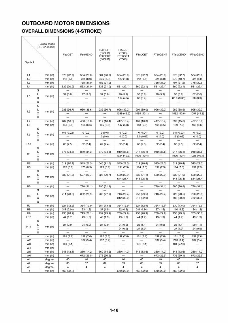
1-18
OUTBOARD MOTOR DIMENSIONSOVERALL DIMENSIONS (4-STROKE)
Global model(US, CA model)
Symbol
F50DET F50HEHD
F50HEHT(F50HB)F60FEHT(F60HB)
FT50JET(T50B)
FT60GET(T60B)
FT50CET FT60GEHT FT50CEHD FT60GEHD
L1 mm (in) 576 (22.7) 584 (23.0) 584 (23.0) 584 (23.0) 576 (22.7) 584 (23.0) 576 (22.7) 584 (23.0)L2 mm (in) 142 (5.6) 225 (8.9) 225 (8.9) 122 (4.8) 142 (5.6) 225 (8.9) 272 (10.7) 225 (8.9)L3 mm (in) — 788 (31.0) 788 (31.0) — — 788 (31.0) 797 (31.2) 778 (30.6)L4 mm (in) 532 (20.9) 533 (21.0) 533 (21.0) 561 (22.1) 560 (22.1) 561 (22.1) 560 (22.1) 561 (22.1)
L5
S
mm (in)
— — — — — — — —L 97 (3.8) 97 (3.8) 97 (3.8) 98 (3.9) 98 (3.9) 98 (3.9) 98 (3.9) 67 (2.6)X — — — 114 (4.5) 85 (3.4) — 85.0 (3.35) 98 (3.9)U — — — — — — — —
L6
S
mm (in)
— — — — — — — —L 933 (36.7) 930 (36.6) 932 (36.7) 996 (39.2) 991 (39.0) 996 (39.2) 989 (38.9) 995 (39.2)X — — — 1099 (43.3) 1095 (43.1) — 1092 (43.0) 1097 (43.2)U — — — — — — — —
L7 mm (in) 407 (16.0) 406 (16.0) 417 (16.4) 417 (16.4) 407 (16.0) 417 (16.4) 397 (15.6) 407 (16.0)L8 mm (in) 148 (5.8) 168 (6.6) 165 (6.5) 147 (5.8) 148 (5.8) 165 (6.5) 189 (7.2) 168 (6.6)
L9
S
mm (in)
— — — — — — — —L 0.6 (0.02) 0 (0.0) 0 (0.0) 0 (0.0) 1.0 (0.04) 0 (0.0) 0.8 (0.03) 0 (0.0)X — — 0 (0.0) 0 (0.0) 16.0 (0.63) 0 (0.0) 16 (0.63) 0 (0.0)U — — — — — — — —
L10 mm (in) 63 (2.5) 62 (2.4) 62 (2.4) 62 (2.4) 63 (2.5) 62 (2.4) 63 (2.5) 62 (2.4)
H1
S
mm (in)
— — — — — — — —L 876 (34.5) 870 (34.3) 870 (34.3) 910 (35.8) 917 (36.1) 910 (35.8) 917 (36.1) 910 (35.8)X — — — 1024 (40.3) 1026 (40.4) — 1026 (40.4) 1025 (40.4)U — — — — — — — —
H2 mm (in) 519 (20.4) 545 (21.5) 545 (21.5) 545 (21.5) 519 (20.4) 545 (21.5) 519 (20.4) 545 (21.5)H3 mm (in) 175 (6.9) 175 (6.9) 175 (6.9) 191 (7.5) 194 (7.6) 191 (7.5) 194 (7.6) 191 (7.5)
H4
S
mm (in)
— — — — — — — —L 533 (21.0) 527 (20.7) 527 (20.7) 530 (20.9) 536 (21.1) 530 (20.9) 533 (21.0) 530 (20.9)X — — — 644 (25.4) 645 (25.4) — 645 (25.4) 644 (25.4)U — — — — — — — —
H5 mm (in) — 790 (31.1) 790 (31.1) — — 790 (31.1) 680 (26.8) 790 (31.1)
H6
S
mm (in)
— — — — — — — —L 711 (28.0) 682 (26.9) 708 (27.9) 746 (29.4) 750 (29.5) 746 (29.4) 723 (28.5) 720 (28.3)X — — — 812 (32.0) 813 (32.0) — 783 (30.8) 782 (30.8)U — — — — — — — —
H7 mm (in) 327 (12.9) 354 (13.9) 354 (13.9) 354 (13.9) 327 (12.9) 354 (13.9) 330 (13.0) 354 (13.9)H8 mm (in) 3.5 (0.14) 33 (1.3) 37 (1.5) 22 (0.9) 3.5 (0.14) 37 (1.5) 110 (4.3) 34 (1.3)H9 mm (in) 733 (28.9) 713 (28.1) 759 (29.9) 759 (29.9) 733 (28.9) 759 (29.9) 738 (29.1) 763 (30.0)
H10 mm (in) 44 (1.7) 49 (1.9) 49 (1.9) 49 (1.9) 44 (1.7) 49 (1.9) 44 (1.7) 49 (1.9)
H11
S
mm (in)
— — — — — — — —L 24 (0.9) 24 (0.9) 24 (0.9) 24 (0.9) 28 (1.1) 24 (0.9) 28 (1.1) 29 (1.1)X — — — 24 (0.9) 27 (1.0) — 27 (1.0) 24 (0.9)U — — — — — — — —
W1 mm (in) 181 (7.1) 192 (7.6) 192 (7.6) 192 (7.6) 181 (7.1) 192 (7.6) 181 (7.1) 192 (7.6)W2 mm (in) — 137 (5.4) 137 (5.4) — — 137 (5.4) 213 (8.4) 137 (5.4)W3 mm (in) 181 (7.1) — — — 181 (7.1) — 181 (7.13) —W4 mm (in) — — — — — — — —W5 mm (in) 345 (13.6) 360 (14.2) 360 (14.2) 360 (14.2) 345 (13.6) 360 (14.2) 345 (13.6) 360 (14.2)W6 mm (in) — 672 (26.5) 672 (26.5) — — 672 (26.5) 738 (29.1) 672 (26.5)A1 degree 40 40 40 40 40 40 40 40 A2 degree 65 67 69 69 65 69 63 67 A3 degree 4 4 4 4 4 4 4 4 T1 mm (in) 560 (22.0) — — 560 (22.0) 560 (22.0) 560 (22.0) 560 (22.0) —
1-19
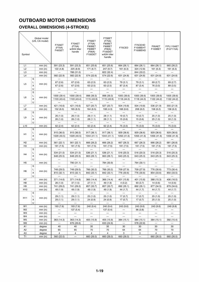
OUTBOARD MOTOR DIMENSIONSOVERALL DIMENSIONS (4-STROKE)
Global model(US, CA model)
Symbol
F70AET(F70A)
F40GET
F70AET(F70A)
w/6X4 tiller handle
F75BET(F75A)
F80BETF90BET(F90A)
F100DET
F75BET(F75A)
F80BETF90BET(F90A)
F100DETw/6X4 tiller
handle
F75CEDF75CEHDF100BEHTF100BEHD
F95AETF100BET
F/FL115AET(F/LF115A)
L1 mm (in) 591 (23.3) 591 (23.3) 651 (25.6) 651 (25.6) 664 (26.1) 664 (26.1) 664 (26.1) 665 (26.2)L2 mm (in) 122 (4.8) 225 (8.9) 171 (6.7) 247 (9.7) 161 (6.3) 324 (12.8) 161 (6.3) 161 (6.3)L3 mm (in) — 788 (31.0) — 822 (32.4) — 844 (33.2) — — L4 mm (in) 582 (22.9) 582 (22.9) 574 (22.6) 574 (22.6) 631 (24.8) 631 (24.8) 631 (24.8) 631 (24.8)
L5
S
mm (in)
— — — — — — — —L 67 (2.6) 67 (2.6) 63 (2.5) 63 (2.5) 79 (3.1) 79 (3.1) 69 (2.7) 69 (2.7)X 67 (2.6) 67 (2.6) 63 (2.5) 63 (2.5) 87 (3.4) 87 (3.4) 76 (3.0) 89 (3.5)U — — — — — — — —
L6
S
mm (in)
— — — — — — — —L 1000 (39.4) 1000 (39.4) 998 (39.3) 998 (39.3) 1005 (39.6) 1005 (39.6) 1005 (39.6) 1005 (39.6)X 1103 (43.4) 1103 (43.4) 1115 (43.9) 1115 (43.9) 1118 (44.0) 1118 (44.0) 1122 (44.2) 1122 (44.2)U — — — — — — — —
L7 mm (in) 421 (16.6) 421 (16.6) 527 (20.7) 527 (20.7) 504 (19.8) 504 (19.8) 536 (21.9) 555 (21.9)L8 mm (in) 152 (6.0) 165 (6.5) 164 (6.5) 108 (4.3) 168 (6.6) 208 (8.2) 158 (6.2) 158 (6.2)
L9
S
mm (in)
— — — — — — — —L 26 (1.0) 26 (1.0) 28 (1.1) 28 (1.1) 19 (0.7) 19 (0.7) 25 (1.0) 25 (1.0)X 26 (1.0) 26 (1.0) 28 (1.1) 28 (1.1) 15 (0.6) 15 (0.6) 25 (1.0) 33 (1.3)U — — — — — — — —
L10 mm (in) 62 (2.4) 62 (2.4) 62 (2.4) 62 (2.4) 75 (3.0) 75 (3.0) 75 (3.0) 75 (3.0)
H1
S
mm (in)
— — — — — — — —L 915 (36.0) 915 (36.0) 917 (36.1) 917 (36.1) 929 (36.6) 929 (36.6) 929 (36.6) 929 (36.6)X 1029 (40.5) 1029 (40.5) 1044 (41.1) 1044 (41.1) 1056 (41.6) 1056 (41.6) 1056 (41.6) 1056 (41.6)U — — — — — — — —
H2 mm (in) 561 (22.1) 561 (22.1) 666 (26.2) 666 (26.2) 667 (26.3) 667 (26.3) 666 (26.2) 681 (26.8)H3 mm (in) 191 (7.5) 191 (7.5) 191 (7.5) 191 (7.5) 191 (7.5) 191 (7.5) 191 (7.5) 191 (7.5)
H4
S
mm (in)
— — — — — — — —L 534 (21.0) 534 (21.0) 536 (21.1) 536 (21.1) 516 (20.3) 516 (20.3) 516 (20.3) 516 (20.3)X 648 (25.5) 648 (25.5) 663 (26.1) 663 (26.1) 643 (25.3) 643 (25.3) 643 (25.3) 643 (25.3)U — — — — — — — —
H5 mm (in) — 790 (31.1) — 784 (30.9) — 764 (30.1) — —
H6
S
mm (in)
— — — — — — — —L 749 (29.5) 749 (29.5) 766 (30.2) 766 (30.2) 709 (27.9) 709 (27.9) 776 (30.6) 773 (30.4)X 815 (32.1) 815 (32.1) 842 (33.1) 842 (33.1) 776 (30.6) 776 (30.6) 854 (33.6) 850 (33.5)U — — — — — — — —
H7 mm (in) 371 (14.6) 371 (14.6) 366 (14.4) 366 (14.4) 401 (15.8) 401 (15.8) 388 (15.3) 406 (16.0)H8 mm (in) 26 (1.0) 37 (1.5) 27 (1.1) 49 (1.9) 4 (0.2) 93 (3.7) 14 (0.6) 14 (0.6)H9 mm (in) 741 (29.2) 741 (29.2) 857 (33.7) 857 (33.7) 892 (35.1) 892 (35.1) 877 (34.5) 879 (34.6)
H10 mm (in) 49 (1.9) 49 (1.9) 49 (1.9) 49 (1.9) 44 (1.7) 44 (1.7) 44 (1.7) 44 (1.7)
H11
S
mm (in)
— — — — — — — —L 29 (1.1) 29 (1.1) 25 (1.0) 25 (1.0) 17 (0.7) 17 (0.7) 25 (1.0) 25 (1.0)X 29 (1.1) 29 (1.1) 24 (0.9) 24 (0.9) 17 (0.7) 17 (0.7) 25 (1.0) 25 (1.0)U — — — — — — — —
W1 mm (in) 193 (7.6) 193 (7.6) 240 (9.4) 240 (9.4) 243 (9.6) 243 (9.6) 243 (9.6) 249 (9.8)W2 mm (in) — 137 (5.4) — 137 (5.4) — 96 (3.8) — —W3 mm (in) — — — — — — — —W4 mm (in) — — — — — — — —W5 mm (in) 363 (14.3) 363 (14.3) 405 (15.9) 405 (15.9) 384 (15.1) 384 (15.1) 384 (15.1) 392 (15.4)W6 mm (in) — 676 (26.6) — 633 (24.9) — 578 (22.8) — —A1 degree 40 40 35 35 30 30 30 30A2 degree 65 65 70 70 64 64 70 70A3 degree 4 4 4 4 3 3 4 4T1 mm (in) 560 (22.0) — 660 (26.0) 660 (26.0) 660 (26.0) — 660 (26.0) 660 (26.0)
1-20
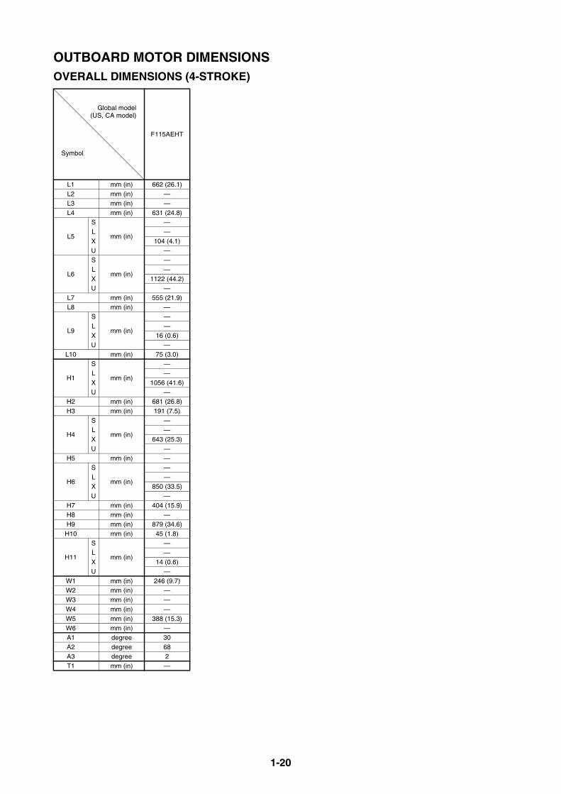
OUTBOARD MOTOR DIMENSIONSOVERALL DIMENSIONS (4-STROKE)
Global model(US, CA model)
Symbol
F115AEHT
L1 mm (in) 662 (26.1)L2 mm (in) —L3 mm (in) —L4 mm (in) 631 (24.8)
L5
S
mm (in)
—L —X 104 (4.1)U —
L6
S
mm (in)
—L —X 1122 (44.2)U —
L7 mm (in) 555 (21.9)L8 mm (in) —
L9
S
mm (in)
—L —X 16 (0.6)U —
L10 mm (in) 75 (3.0)
H1
S
mm (in)
—L —X 1056 (41.6)U —
H2 mm (in) 681 (26.8)H3 mm (in) 191 (7.5)
H4
S
mm (in)
—L —X 643 (25.3)U —
H5 mm (in) —
H6
S
mm (in)
—L —X 850 (33.5)U —
H7 mm (in) 404 (15.9)H8 mm (in) —H9 mm (in) 879 (34.6)
H10 mm (in) 45 (1.8)
H11
S
mm (in)
—L —X 14 (0.6)U —
W1 mm (in) 246 (9.7)W2 mm (in) —W3 mm (in) —W4 mm (in) —W5 mm (in) 388 (15.3)W6 mm (in) —A1 degree 30 A2 degree 68 A3 degree 2T1 mm (in) —
1-21
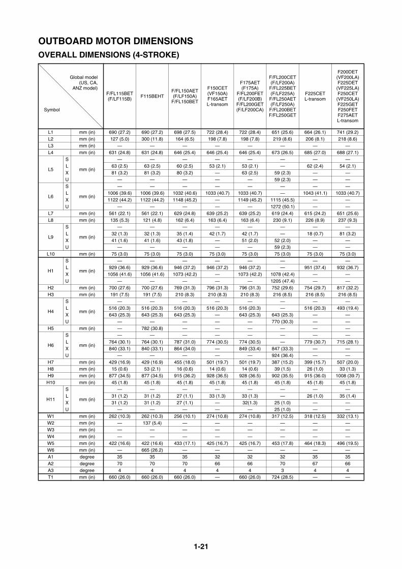
OUTBOARD MOTOR DIMENSIONSOVERALL DIMENSIONS (4-STROKE)
Global model(US, CA,
ANZ model)
Symbol
F/FL115BET(F/LF115B)
F115BEHTF/FL150AET(F/LF150A)
F/FL150BET
F150CET(VF150A)F165AETL-transom
F175AET(F175A)
F/FL200FET(F/LF200B)
F/FL200GET(F/LF200CA)
F/FL200CET(F/LF200A)
F/FL225BET(F/LF225A)
F/FL250AET(F/LF250A)
F/FL200BETF/FL250GET
F225CETL-transom
F200DET(VF200LA)F225DET(VF225LA)F250CET(VF250LA)F225GETF250FETF275AETL-transom
L1 mm (in) 690 (27.2) 690 (27.2) 698 (27.5) 722 (28.4) 722 (28.4) 651 (25.6) 664 (26.1) 741 (29.2)L2 mm (in) 127 (5.0) 300 (11.8) 164 (6.5) 198 (7.8) 198 (7.8) 219 (8.6) 206 (8.1) 218 (8.6)L3 mm (in) — — — — — — — —L4 mm (in) 631 (24.8) 631 (24.8) 646 (25.4) 646 (25.4) 646 (25.4) 673 (26.5) 685 (27.0) 688 (27.1)
L5
S
mm (in)
— — — — — — — —L 63 (2.5) 63 (2.5) 60 (2.5) 53 (2.1) 53 (2.1) — 62 (2.4) 54 (2.1)X 81 (3.2) 81 (3.2) 80 (3.2) — 63 (2.5) 59 (2.3) — —U — — — — — 59 (2.3) — —
L6
S
mm (in)
— — — — — — — —L 1006 (39.6) 1006 (39.6) 1032 (40.6) 1033 (40.7) 1033 (40.7) — 1043 (41.1) 1033 (40.7)X 1122 (44.2) 1122 (44.2) 1148 (45.2) — 1149 (45.2) 1115 (45.5) — —U — — — — — 1272 (50.1) — —
L7 mm (in) 561 (22.1) 561 (22.1) 629 (24.8) 639 (25.2) 639 (25.2) 619 (24.4) 615 (24.2) 651 (25.6)L8 mm (in) 135 (5.3) 121 (4.8) 162 (6.4) 163 (6.4) 163 (6.4) 230 (9.1) 226 (8.9) 237 (9.3)
L9
S
mm (in)
— — — — — — — —L 32 (1.3) 32 (1.3) 35 (1.4) 42 (1.7) 42 (1.7) — 18 (0.7) 81 (3.2)X 41 (1.6) 41 (1.6) 43 (1.8) — 51 (2.0) 52 (2.0) — —U — — — — — 59 (2.3) — —
L10 mm (in) 75 (3.0) 75 (3.0) 75 (3.0) 75 (3.0) 75 (3.0) 75 (3.0) 75 (3.0) 75 (3.0)
H1
S
mm (in)
— — — — — — — —L 929 (36.6) 929 (36.6) 946 (37.2) 946 (37.2) 946 (37.2) — 951 (37.4) 932 (36.7)X 1056 (41.6) 1056 (41.6) 1073 (42.2) — 1073 (42.2) 1078 (42.4) — —U — — — — — 1205 (47.4) — —
H2 mm (in) 700 (27.6) 700 (27.6) 769 (31.3) 796 (31.3) 796 (31.3) 752 (29.6) 754 (29.7) 817 (32.2)H3 mm (in) 191 (7.5) 191 (7.5) 210 (8.3) 210 (8.3) 210 (8.3) 216 (8.5) 216 (8.5) 216 (8.5)
H4
S
mm (in)
— — — — — — — —L 516 (20.3) 516 (20.3) 516 (20.3) 516 (20.3) 516 (20.3) — 516 (20.3) 493 (19.4)X 643 (25.3) 643 (25.3) 643 (25.3) — 643 (25.3) 643 (25.3) — —U — — — — — 770 (30.3) — —
H5 mm (in) — 782 (30.8) — — — — — —
H6
S
mm (in)
— — — — — — — —L 764 (30.1) 764 (30.1) 787 (31.0) 774 (30.5) 774 (30.5) — 779 (30.7) 715 (28.1)X 840 (33.1) 840 (33.1) 864 (34.0) — 849 (33.4) 847 (33.3) — —U — — — — — 924 (36.4) — —
H7 mm (in) 429 (16.9) 429 (16.9) 455 (18.0) 501 (19.7) 501 (19.7) 387 (15.2) 399 (15.7) 507 (20.0)H8 mm (in) 15 (0.6) 53 (2.1) 16 (0.6) 14 (0.6) 14 (0.6) 39 (1.5) 26 (1.0) 33 (1.3)H9 mm (in) 877 (34.5) 877 (34.5) 915 (36.2) 928 (36.5) 928 (36.5) 902 (35.5) 915 (36.0) 1008 (39.7)
H10 mm (in) 45 (1.8) 45 (1.8) 45 (1.8) 45 (1.8) 45 (1.8) 45 (1.8) 45 (1.8) 45 (1.8)
H11
S
mm (in)
— — — — — — — —L 31 (1.2) 31 (1.2) 27 (1.1) 33 (1.3) 33 (1.3) — 26 (1.0) 35 (1.4)X 31 (1.2) 31 (1.2) 27 (1.1) — 32(1.3) 25 (1.0) — —U — — — — — 25 (1.0) — —
W1 mm (in) 262 (10.3) 262 (10.3) 256 (10.1) 274 (10.8) 274 (10.8) 317 (12.5) 318 (12.5) 332 (13.1)W2 mm (in) — 137 (5.4) — — — — — —W3 mm (in) — — — — — — — —W4 mm (in) — — — — — — — —W5 mm (in) 422 (16.6) 422 (16.6) 433 (17.1) 425 (16.7) 425 (16.7) 453 (17.8) 464 (18.3) 496 (19.5)W6 mm (in) — 665 (26.2) — — — — — —A1 degree 35 35 35 32 32 32 35 35A2 degree 70 70 70 66 66 70 67 66A3 degree 4 4 4 4 4 3 4 4T1 mm (in) 660 (26.0) 660 (26.0) 660 (26.0) — 660 (26.0) 724 (28.5) — —
1-22
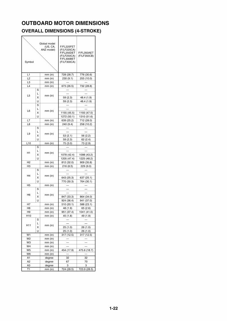
OUTBOARD MOTOR DIMENSIONSOVERALL DIMENSIONS (4-STROKE)
Global model(US, CA,
ANZ model)
Symbol
F/FL225FET(F/LF225CA)F/FL250DET(F/LF250CA)F/FL300BET(F/LF300CA)
F/FL350AET(F/LF350CB)
L1 mm (in) 728 (28.7) 776 (30.6)L2 mm (in) 230 (9.1) 255 (10.0)L3 mm (in) — —L4 mm (in) 673 (26.5) 732 (28.8)
L5
S
mm (in)
— —L — —X 59 (2.3) 48.4 (1.9)U 59 (2.3) 48.4 (1.9)
L6
S
mm (in)
— —L — —X 1155 (45.5) 1193 (47.0)U 1272 (50.1) 1310 (51.6)
L7 mm (in) 639 (25.2) 712 (28.0)L8 mm (in) 240 (9.4) 258 (10.2)
L9
S
mm (in)
— —L — —X 53 (2.1) 56 (2.2)U 59 (2.3) 62 (2.4)
L10 mm (in) 75 (3.0) 73 (2.9)
H1
S
mm (in)
— —L — —X 1078 (42.4) 1098 (43.2)U 1205 (47.4) 1225 (48.2)
H2 mm (in) 812 (32.0) 909 (35.8)H3 mm (in) 216 (8.5) 229 (9.0)
H4
S
mm (in)
— —L — —X 643 (25.3) 637 (25.1)U 770 (30.3) 764 (30.1)
H5 mm (in) — —
H6
S
mm (in)
— —L — —X 847 (33.3) 864 (34.0)U 924 (36.4) 941 (37.0)
H7 mm (in) 510 (20.1) 588 (23.1)H8 mm (in) 48 (1.9) 65 (2.6)H9 mm (in) 951 (37.4) 1041 (41.0)
H10 mm (in) 45 (1.8) 49 (1.9)
H11
S
mm (in)
— —L — —X 25 (1.0) 26 (1.0)U 25 (1.0) 26 (1.0)
W1 mm (in) 317 (12.5) 317 (12.5)W2 mm (in) — —W3 mm (in) — —W4 mm (in) — —W5 mm (in) 454 (17.9) 475.6 (18.7)W6 mm (in) — —A1 degree 32 32A2 degree 67 70A3 degree 3 3T1 mm (in) 724 (28.5) 723.9 (28.5)

1-23
OUTBOARD MOTOR DIMENSIONSOVERALL DIMENSIONS (2-STROKE)
Global model(US, CA model)
Symbol
2CMH 3AMH4ACMH5CMH
5CSMH
6CMH8CMH
E8DMHEK8DMH
15FMH
E9.9DMHE15DMH
EK9.9DMHEK15DMHEK9.9JMHEK15PMH
20DMH25NWC25NMH
25NMHO
L1 mm (in) 275 (10.8) 311 (12.2) 344 (13.5) 363 (14.3) 346 (13.6) 393 (15.5) 405 (15.9) 428 (16.9) L2 mm (in) 122 (4.8) 107 (4.2) 145 (5.7) 114 (4.5) 180 (7.1) 180 (7.1) 165 (6.5) 185 (7.3)L3 mm (in) 328 (12.9) 317 (12.5) 333 (13.1) 439 (17.3) 372 (14.6) 479 (18.9) 473 (18.6) 508 (20.0) L4 mm (in) 164 (6.5) 223 (8.8) 252 (9.9) 359 (14.1) 268 (10.6) 355 (14.0) 357 (14.0) 402 (15.8)
L5
S
mm (in)
34 (1.3) 16 (0.6) 16 (0.6) 121 (4.8) 23 (0.9) 78 (3.1) 79 (3.1) 79 (3.1)L — — 24 (0.9) 126 (5.0) 23 (0.9) 104 (4.1) 78 (3.1) 106 (4.2)Y — — — — — — — —X — — — 126 (5.0) 23 (0.9) — 78 (3.1) —U — — — — — 134 (5.3) — —
L6
S
mm (in)
589 (23.2) 636 (25.0) 635 (25.0) 705 (27.8) 657 (25.9) 718 (28.3) 708 (27.9) 739 (29.1)L — — 758 (29.8) 826 (32.5) 782 (30.8) 831 (32.7) 821 (32.3) 852 (33.5)Y — — — — — — — —X — — — — — — 947 (37.3) —U — — — — — — — —
L7 mm (in) 276 (10.9) 311 (12.2) 331 (13.0) 287 (11.3) 354 (13.9) 314 (12.4) 334 (13.1) 337 (13.3) L8 mm (in) 142 (5.6) 156 (6.1) 148 (5.8) 154 (6.1) 207 (8.1) 263 (10.4) 165 (6.5) 242 (9.5)
L9
S
mm (in)
— — — — — — 0 (0.0) — L — — — — — — 4 (0.2) —Y — — — — — — — —X — — — — — — 14 (0.5) —U — — — — — — — —
L10 mm (in) 50 (2.0) 68 (2.7) 68 (2.7) 65 (2.5) 45 (1.8) 75 (3.0) 73 (2.9) 78 (3.1)
H1
S
mm (in)
614 (24.2) 654 (25.7) 653 (25.7) 682 (26.9) 685 (27.0) 705 (27.8) 706 (27.8) 703 (27.7)L — — 780 (30.7) 809 (31.9) 825 (32.5) 832 (32.8) 833 (32.8) 830 (32.7)Y — — — — — — — —X — — — — — — 975 (38.4) —U — — — — — — — —
H2 mm (in) 302 (11.9) 343 (13.5) 358 (14.1) 295 (11.6) 359 (14.1) 335 (13.2) 356 (14.0) 365 (14.4) H3 mm (in) 100 (3.9) 103 (4.1) 105 (4.1) 123 (4.8) 122 (4.8) 135 (5.3) 34 (1.4) 144 (5.7)
H4
S
mm (in)
417 (16.4) 441 (17.4) 444 (17.5) 436 (17.2) 442 (17.4) 440 (17.3) 441 (17.4) 419 (16.5)L — — 571 (22.5) 563 (22.2) 582 (22.9) 567 (22.3) 568 (22.4) 546 (21.5)Y — — — — — — — —X — — — — — — 710 (27.9) —U — — — — — — — —
H5 mm (in) 462 (18.2) 484 (19.1) 396 (15.6) 462 (18.2) 415 (16.3) 467 (18.4) 474 (18.7) 491 (19.3)
H6
S
mm (in)
503 (19.8) 621 (24.4) 623 (24.5) 668 (26.3) 497 (19.6) 572 (22.5) 569 (22.4) 586 (23.1)L — — 719 (28.3) 758 (29.8) 574 (22.6) 641 (25.2) 638 (25.2) 655 (25.8)Y — — — — — — — —X — — — — — — 714 (28.1) —U — — — — — — — —
H7 mm (in) 38 (1.5) 342 (13.5) 104 (4.1) 110 (4.3) 86 (3.4) 138 (5.4) — 186 (7.3) H8 mm (in) 12 (0.5) 9 (0.35) 30 (1.2) 2.0 (0.08) 51 (2.0) 19 (0.7) 24 (0.9) 24 (0.9) H9 mm (in) 397 (15.6) 419 (16.5) 459 (18.1) 470 (18.5) 465 (18.3) 526 (20.7) 555 (21.9) 584 (23.0)
H10 mm (in) 27 (1.0) 30 (1.2) 30 (1.2) 32 (1.3) 26 (1.0) 34 (1.3) 34 (1.4) 41 (1.6)
H11
S
mm (in)
— — — — — — — — L — — — — — — — —Y — — — — — — — —X — — — — — — — —U — — — — — — — —
W1 mm (in) 151 (5.9) 108 (4.3) 144 (5.7) 150 (5.9) 136 (5.4) 143 (5.6) 173 (6.8) —W2 mm (in) 125 (4.9) 181 (7.1) 178 (7.0) 193 (7.6) 192 (7.6) 189 (7.4) — 206 (8.1) W3 mm (in) 89 (3.5) 105 (4.1) 134 (5.3) 137 (5.4) 129 (5.1) 143 (5.6) — 152 (6.0) W4 mm (in) — — — — 158 (6.2) — 185 (7.3) 177 (7.0) W5 mm (in) — — — 283 (11.1) — 280 (11.0) 280 (11.0) 296 (11.7) W6 mm (in) — — — 551 (21.7) — 497 (19.6) 493 (19.4) 528 (20.8) A1 degree 360 360 360 60 360 45(P)/40(S) 40 40A2 degree 73 76 76 81 80 63 63 67 A3 degree — — — — — — 4 — T1 mm (in) — — — — — — — —

1-24
OUTBOARD MOTOR DIMENSIONSOVERALL DIMENSIONS (2-STROKE)
Global model(US, CA model)
Symbol
E/25BMH25BWC25XMH
E/30HMH30HWH30HWC
EK25BMHEK25CMH
25BW30HW
30DMH30DMHO
30DEO 30DETOE40GWHE40GMH
EK40GMH
E40JMHE40JWHEK40JMH
E40JW
L1 mm (in) 429 (16.9) 429 (16.9) 465 (18.3) 465 (18.3) 489 (19.2) 504 (19.8) 504 (19.8) 504 (19.8)L2 mm (in) 180 (7.1) 180 (7.09) 198 (7.8) 114 (4.5) 89 (3.5) 188 (7.4) 188 (7.4) 188 (7.4)L3 mm (in) 420 (16.5) — 497 (19.6) — — 493 (19.4) 493 (19.4) —L4 mm (in) 385 (15.2) 385 (15.2) 496 (19.5) 496 (19.5) 520 (20.5) 421 (16.6) 421 (16.6) 478 (18.8)
L5
S
mm (in)
61 (2.4) — 85 (3.3) 85 (3.3) — 94 (3.7) 94 (3.7) —L 83 (3.3) 83 (3.3) 90 (3.5) 90 (3.5) 103 (4.1) 94 (3.7) 94 (3.7) 94 (3.7)Y — — — 99 (3.9) — — 94 (3.7) —X 83 (3.3) — — — — — — —U — — — — — — — —
L6
S
mm (in)
736 (29.0) — 752 (29.6) 752 (29.6) — 784 (30.9) 784 (30.9) —L 854 (33.6) 854 (33.6) 859 (33.8) 859 (33.8) 870 (34.2) 897 (35.3) 897 (35.3) 910 (35.8)Y — — — 895 (35.2) — — 943 (37.1) —X 933 (36.7) — — — — — — —U — — — — — — — —
L7 mm (in) 405 (16.0) 405 (15.9) 387 (15.2) 375 (14.8) 356 (14.0) 427 (16.8) 427 (16.8) 427 (16.8)L8 mm (in) 195 (7.7) 195 (7.7) 228 (9.0) 173 (6.8) 158 (6.2) 193 (7.6) 193 (7.6) 193 (7.6)
L9
S
mm (in)
— — — — — — — —L — — — — — — — —Y — — — — — — — —X — — — — — — — —U — — — — — — — —
L10 mm (in) 74.2 (2.9) 74.2 (2.9) 73 (2.9) 73 (2.9) 65 (2.6) 72 (2.8) 72 (2.8) 72 (2.8)
H1
S
mm (in)
707 (27.8) — 712 (28.0) 712 (28.0) — 771 (30.4) 771 (30.4) —L 834 (32.8) 834 (32.8) 833 (32.8) 833 (32.8) 835 (32.9) 898 (35.4) 898 (35.4) 891 (35.1)Y — — — 874 (34.4) — — 948 (37.3) —X 920 (36.2) — — — — — — —U — — — — — — — —
H2 mm (in) 439 (17.3) 439 (17.3) 446 (17.6) 428 (16.9) 426 (16.8) 444 (17.5) 444 (17.5) 444 (17.5)H3 mm (in) 144 (5.7) 144 (5.7) 148 (5.8) 148 (5.8) 148 (5.8) 162 (6.4) 162 (6.4) 175 (6.9)
H4
S
mm (in)
423 (16.6) — 424 (16.7) 424 (16.7) — 444 (17.5) 444 (17.5) —L 550 (21.6) 550 (21.6) 545 (21.5) 545 (21.5) 547 (21.5) 570 (22.4) 570 (22.4) 548 (21.6)Y — — — 586 (23.1) — — 622 (24.5) —X 636 (25.0) — — — — — — —U — — — — — — — —
H5 mm (in) 466 (18.3) — 445 (17.5) — — 533 (21.0) 533 (21.0) 533 (21.0)
H6
S
mm (in)
621 (24.4) — 584 (23.0) 584 (23.0) — 622 (24.5) 622 (24.5) —L 701 (27.6) 701 (27.6) 648 (25.5) 648 (25.5) 651 (25.6) 691 (27.2) 691 (27.2) 683 (26.9)Y — — — 670 (26.4) — — 719 (28.3) —X 754 (29.7) — — — — — — —U — — — — — — — —
H7 mm (in) 118 (4.6) 118 (4.65) 278 (10.9) 224 (8.8) 244 (9.6) 127 (5.0) 127 (5.0) 127 (5.0)H8 mm (in) 30 (1.2) 30 (1.2) 29 (1.1) 9 (0.3) 8.7 (0.3) 30 (1.2) 30 (1.2) 30 (1.2)H9 mm (in) 596 (23.5) 596 (23.5) 657 (25.9) 647 (25.5) 661 (26.0) 695 (27.4) 695 (27.4) 695 (27.4)
H10 mm (in) 40 (1.6) 40.3 (1.6) 44 (1.7) 44 (1.7) 42 (16.5) 45 (1.8) 45 (1.8) 45 (1.8)
H11
S
mm (in)
— — — — — — — —L — — — — 22 (0.9) — — —Y — — — — — — — —X — — — — — — — —U — — — — — — — —
W1 mm (in) 166 (6.5) 166 (6.54) — 154 (6.1) 154 (6.1) 190 (7.5) 190 (7.5) 190 (7.5)W2 mm (in) 233 (9.2) — 208 (8.2) — 152 (6.0) 294 (11.6) 294 (11.6) —W3 mm (in) 148 (5.8) 148 (5.83) 152 (6.0) — — 173 (6.8) 173 (6.8) 173 (6.8)W4 mm (in) 192 (7.6) 192 (7.56) 179 (7.0) — — 205 (8.1) 205 (8.1) 205 (8.1)W5 mm (in) 302 (11.9) 302 (11.89) 310 (12.2) 310 (12.2) 310 (12.2) 360 (14.2) 360 (14.2) 360 (14.2)W6 mm (in) 472 (18.6) 217 (8.54) 522 (20.6) — — 602 (23.7) 602 (23.7) 602 (23.7)A1 degree 40 40 40 40 40 45 45 45A2 degree 68 68 70 70 61 67 67 67A3 degree — — — — 4 — — —T1 mm (in) — — — — — — — —
1-25
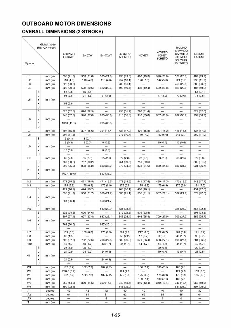
OUTBOARD MOTOR DIMENSIONSOVERALL DIMENSIONS (2-STROKE)
Global model(US, CA model)
Symbol
E/40XMHE40XWH
E/40XW E/40XWT 40VMHO50HMHO
40VEO40VETO50HET
50HETO
40VMHD40VWHDO40VWHTO50HMHD50HWHD
50HWHTO
E48CMHE55CMH
L1 mm (in) 533 (21.8) 553 (21.8) 533 (21.8) 490 (19.3) 490 (19.3) 528 (20.8) 528 (20.8) 487 (19.2) L2 mm (in) 118 (4.6) 118 (4.6) 118 (4.6) 257 (10.1) 178 (7.0) 142 (5.6) 221 (8.7) 298 (11.7) L3 mm (in) 523 (20.6) — — 789 (31.1) — — 753 (29.6) 680 (26.8) L4 mm (in) 522 (20.6) 522 (20.6) 522 (20.6) 493 (19.4) 493 (19.4) 529 (20.8) 529 (20.8) 487 (19.2)
L5
S
mm (in)
65 (2.6) 65 (2.6) — — — — — 54 (2.1)L 91 (3.6) 91 (3.6) 91 (3.6) — — 77 (3.0) 77 (3.0) 71 (2.8)Y — — — — — — — —X 91 (3.6) — — — — — — —U — — — — — — — —
L6
S
mm (in)
826 (32.5) 826 (32.5) — 798 (31.4) 798 (31.4) — — 827 (32.6)L 940 (37.0) 940 (37.0) 935 (36.8) 910 (35.8) 910 (35.8) 937 (36.9) 937 (36.9) 932 (36.7)Y — — — — — — — —X 1043 (41.1) — 935 (36.8) — — — — —U — — — — — — — —
L7 mm (in) 397 (15.6) 397 (15.6) 391 (15.4) 433 (17.0) 401 (15.8) 387 (15.2) 418 (16.5) 437 (17.2)L8 mm (in) 294 (11.6) — — 273 (10.7) 179 (7.0) 153 (6.0) 246 (9.7) 280 (11.0)
L9
S
mm (in)
3 (0.1) 3 (0.1) — — — — —L 8 (0.3) 8 (0.3) 8 (0.3) — — 10 (0.4) 10 (0.4) —Y — — — — — — — —X 16 (0.6) — 8 (0.3) — — — — —U — — — — — — — —
L10 mm (in) 65 (2.6) 65 (2.6) 65 (2.6) 72 (2.8) 72 (2.8) 63 (2.5) 63 (2.5) 77 (3.0)
H1
S
mm (in)
767 (30.2) 767 (30.2) — 751 (29.6) 751 (29.6) — — 809 (31.9)L 893 (35.2) 893 (35.2) 893 (35.2) 878 (34.6) 878 (34.6) 880 (34.6) 880 (34.6) 931 (36.7)Y — — — — — — — —X 1007 (39.6) — 893 (35.2) — — — — —U — — — — — — — —
H2 mm (in) 471 (18.5) 471 (18.5) 471 (18.5) 472 (18.6) 441 (17.4) 439 (17.3) 470 (18.5) 449 (17.7)H3 mm (in) 175 (6.9) 175 (6.9) 175 (6.9) 175 (6.9) 175 (6.9) 175 (6.9) 175 (6.9) 191 (7.5)
H4
S
mm (in)
424 (16.7) 424 (16.7) — 408 (16.1) 408 (16.1) — — 451 (17.8)L 550 (21.7) 550 (21.7) 550 (21.7) 535 (21.1) 535 (21.1) 537 (21.1) 537 (21.1) 572 (22.5)Y — — — — — — — —X 664 (26.1) — 550 (21.7) — — — — —U — — — — — — — —
H5 mm (in) — — 532 (20.9) 731 (28.8) — — 728 (28.7) 568 (22.4)
H6
S
mm (in)
626 (24.6) 626 (24.6) — 579 (22.8) 579 (22.8) — — 591 (23.3)L 697 (27.4) 697 (27.4) 637 (25.1) 646 (25.4) 646 (25.4) 709 (27.9) 709 (27.9) 652 (25.7)Y — — — — — — — —X 761 (30.0) — 637 (25.1) — — — — —U — — — — — — — —
H7 mm (in) 159 (6.3) 159 (6.3) 176 (6.9) 201 (7.9) 217 (8.5) 222 (8.7) 204 (8.0) 171 (6.7)H8 mm (in) 38 (1.5) — — 55 (2.2) 17 (0.7) 0 (0.0) 43 (1.7) 93 (3.7) H9 mm (in) 702 (27.6) 702 (27.6) 706 (27.8) 683 (26.9) 671 (26.4) 688 (27.1) 696 (27.4) 684 (26.9)
H10 mm (in) 43 (1.7) 43 (1.7) 43 (1.7) 44 (1.7) 44 (1.7) 44 (1.7) 44 (1.7) 42 (1.7)
H11
S
mm (in)
25 (1.0) 25 (1.0) — — — 20 (0.8) — 22 (0.9)L 24 (0.9) 24 (0.9) 24 (0.9) — — 19 (0.7) 19 (0.7) 21 (0.8)Y — — — — — — — —X 24 (0.9) — 24 (0.9) — — — — —U — — — — — — — —
W1 mm (in) 182 (7.2) 182 (7.2) 182 (7.2) — 180 (7.1) 180 (7.1) 180 (7.1) —W2 mm (in) 220.5 (8.7) — — 124 (4.9) — — 124 (4.9) 159 (6.3) W3 mm (in) 182 (7.2) 182 (7.2) 182 (7.2) 175 (6.9) 175 (6.9) 175 (6.9) 175 (6.9) 165 (6.5)W4 mm (in) — — — — 180 (7.1) 180 (7.1) 180 (7.1) —W5 mm (in) 369 (14.5) 369 (14.5) 369 (14.5) 340 (13.4) 340 (13.4) 340 (13.4) 340 (13.4) 268 (10.6)W6 mm (in) 592 (23.3) — — 641 (25.2) — — 641 (25.2) 507 (20.0)A1 degree 42 42 42 40 40 40 40 30 A2 degree 64 64 61 62 62 65 65 64A3 degree — — 4 — — 4 4 —T1 mm (in) — — — — — — — —
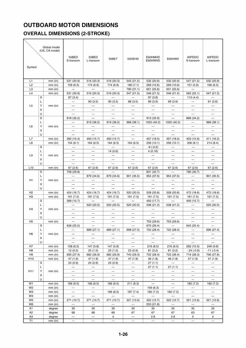
1-26
OUTBOARD MOTOR DIMENSIONSOVERALL DIMENSIONS (2-STROKE)
Global model(US, CA model)
Symbol
55BEDS-transom
55BEDL-transom
55BET 55DEHD E60HMHDE60HWHD
E60HWD 60FEDOS-transom
60FEDOL-transom
L1 mm (in) 531 (20.9) 516 (20.3) 516 (20.3) 545 (21.5) 532 (20.9) 532 (20.9) 547 (21.5) 532 (20.9)L2 mm (in) 159 (6.3) 174 (6.9) 174 (6.9) 180 (7.1) 269 (10.6) 269 (10.6) 151 (5.9) 166 (6.5)L3 mm (in) — — — 790 (31.1) 651 (25.6) 651 (25.6) — —L4 mm (in) 531 (20.9) 516 (20.3) 516 (20.3) 547 (21.5) 546 (21.5) 546 (21.5) 562 (22.1) 547 (21.5)
L5
S
mm (in)
87 (3.4) — — — 97 (3.8) — 113 (4.4) —L — 90 (3.5) 90 (3.5) 88 (3.5) 99 (3.9) 99 (3.9) — 91 (3.6)Y — — — — — — — —X — — — — — — — —U — — — — — — — —
L6
S
mm (in)
818 (32.2) — — — 913 (35.9) — 868 (34.2) —L — 919 (36.2) 919 (36.2) 968 (38.1) 1020 (40.2) 1020 (40.2) — 968 (38.1)Y — — — — — — — —X — — — — — — — —U — — — — — — — —
L7 mm (in) 392 (15.4) 400 (15.7) 400 (15.7) — 457 (18.0) 457 (18.0) 403 (15.9) 411 (16.2)L8 mm (in) 154 (6.1) 164 (6.5) 164 (6.5) 164 (6.5) 256 (10.1) 256 (10.1) 206 (8.1) 214 (8.4)
L9
S
mm (in)
— — — — -6 (-0.2) — — —L — — 14 (0.6) — 4 (0.16) — — —Y — — — — — — — —X — — — — — — — —U — — — — — — — —
L10 mm (in) 67 (2.6) 67 (2.6) 67 (2.6) 67 (2.6) 67 (2.6) 67 (2.6) 67 (2.6) 67 (2.6)
H1
S
mm (in)
758 (29.8) — — — 831 (32.7) — 780 (30.7) —L — 879 (34.6) 879 (34.6) 901 (35.5) 954 (37.6) 954 (37.6) — 901 (35.5)Y — — — — — — — —X — — — — — — — —U — — — — — — — —
H2 mm (in) 424 (16.7) 424 (16.7) 424 (16.7) 520 (20.5) 528 (20.8) 528 (20.8) 472 (18.6) 472 (18.6)H3 mm (in) 191 (7.5) 191 (7.5) 191 (7.5) 191 (7.5) 191 (7.5) 191 (7.5) 191 (7.5) 191 (7.5)
H4
S
mm (in)
399 (15.7) — — — 450 (17.7) — 400 (15.7) —L — 520 (20.5) 520 (20.5) 520 (20.5) 538 (21.2) 538 (21.2) — 520 (20.5)Y — — — — — — — —X — — — — — — — —U — — — — — — — —
H5 mm (in) — — — — 753 (29.6) 753 (29.6) — —
H6
S
mm (in)
636 (25.0) — — — 670 (26.4) — 645 (25.4) —L — 689 (27.1) 689 (27.1) 698 (27.5) 722 (28.4) 722 (28.4) — 696 (27.4)Y — — — — — — — —X — — — — — — — —U — — — — — — — —
H7 mm (in) 158 (6.2) 147 (5.8) 147 (5.8) — 216 (8.5) 216 (8.5) 262 (10.3) 249 (9.8)H8 mm (in) 12 (0.5) 25 (1.0) 25 (1.0) 23 (0.9) 81 (3.2) 81 (3.2) - 24 (-0.9) -11 (-0.4)H9 mm (in) 695 (27.4) 682 (26.9) 682 (26.9) 743 (29.3) 722 (28.4) 722 (28.4) 719 (28.3) 706 (27.8)
H10 mm (in) 47 (1.9) 47 (1.9) 47 (1.9) 47 (1.9) 46 (1.8) 46 (1.8) 47 (1.9) 47 (1.9)
H11
S
mm (in)
24 (0.9) 24 (0.9) 24 (0.9) — 27 (1.1) — — —L — — — — 27 (1.1) 27 (1.1) — —Y — — — — — — — —X — — — — — — — —U — — — — — — — —
W1 mm (in) 166 (6.5) 166 (6.5) 166 (6.5) 211 (8.3) — — 182 (7.2) 182 (7.2) W2 mm (in) — — — — 159 (6.3) — — —W3 mm (in) — — 166 (6.5) 187 (7.4) 182 (7.2) 182 (7.2) — —W4 mm (in) — — — — — — — —W5 mm (in) 271 (10.7) 271 (10.7) 271 (10.7) 331 (13.0) 322 (12.7) 322 (12.7) 321 (12.6) 321 (12.6) W6 mm (in) — — — — 553 (21.8) — — —A1 degree 30 30 30 30 35 35 35 35A2 degree 68 68 68 67 67 67 63 67A3 degree — — 4 — 2.8 2.8 0 4T1 mm (in) — — — — — — — —

1-27
OUTBOARD MOTOR DIMENSIONSOVERALL DIMENSIONS (2-STROKE)
Global model(US, CA model)
Symbol
60FETO70BETO
S-transom
60FET60FETO70BETO
L-transom
55DEHD75AEHD85AEHD
75AED85AED
75AET85AET
E75BMHD 75CETO90AETO
E115AMHE115AWH
L1 mm (in) 547 (21.5) 532 (20.9) 545 (21.5) 545 (21.5) 545 (21.5) 545 (21.5) 545 (21.5) 539 (21.2)L2 mm (in) 151 (5.9) 166 (6.5) 180 (7.1) 180 (7.1) 180 (7.1) 270 (10.6) 180 (7.1) 325 (12.8)L3 mm (in) — — 790 (31.1) — — 652 (25.7) — 845 (33.3)L4 mm (in) 562 (22.1) 547 (21.5) 547 (21.5) 547 (21.5) 547 (21.5) 547 (21.5) 547 (21.5) 616 (24.3)
L5
S
mm (in)
113 (4.4) — — — — — — —L — 91 (3.6) 88 (3.5) 88 (3.5) 88 (3.5) 81 (3.2) 88 (3.5) 80 (3.1)Y — — 85 (3.3) — — 80 (3.1) — 75 (3.0)X — — 85 (3.3) 80 (3.1) 80 (3.1) 70 (2.8) 80 (3.1) 85 (3.3)U — — — — — — — —
L6
S
mm (in)
868 (34.2) — — — — — — —L — 968 (38.1) 968 (38.1) 968 (38.1) 968 (38.1) 966 (38.0) 968 (38.1) 1005 (39.6)Y — — 1015 (40.0) — — 1011 (39.8) — 1055 (41.5)X — — 1080 (42.5) 1080 (42.5) 1080 (42.5) 1078 (42.4) 1080 (42.5) 1120 (44.1)U — — — — — — — —
L7 mm (in) 403 (15.9) 411 (16.2) 459 (18.1) 459 (18.1) 459 (18.1) 542 (21.3) 457 (18.0) 570 (22.4)L8 mm (in) 206 (8.1) 214 (8.4) 164 (6.5) 164 (6.5) 164 (6.5) 256 (10.1) 164 (6.5) 270 (10.6)
L9
S
mm (in)
0.0 (0.0) — — — — — — —L — 14 (0.6) — — 14 (0.6) — 14 (0.6) —Y — — — — — — — —X — — — — 23 (0.9) — 31 (1.2) —U — — — — — — — —
L10 mm (in) 67 (2.6) 67 (2.6) 67 (2.6) 67 (2.6) 67 (2.6) 68 (2.7) 67 (2.6) 64 (2.5)
H1
S
mm (in)
780 (30.7) — — — — — — —L — 901 (35.5) 901 (35.5) 901 (35.5) 901 (35.5) 902 (35.5) 901 (35.5) 929 (36.6)Y — — 952 (37.5) — — 953 (37.5) — 982 (38.7)X — — 1028 (40.5) 1028 (40.5) 1028 (40.5) 1028 (40.5) 1028 (40.5) 1056 (41.6)U — — — — — — — —
H2 mm (in) 472 (18.6) 472 (18.6) 520 (20.5) 520 (20.5) 520 (20.5) 590 (23.2) 512 (20.2) 631 (24.8)H3 mm (in) 191 (7.5) 191 (7.5) 191 (7.5) 191 (7.5) 191 (7.5) 191 (7.5) 191 (7.5) 190 (7.5)
H4
S
mm (in)
400 (15.7) — — — — — — —L — 520 (20.5) 520 (20.5) 520 (20.5) 520 (20.5) 521 (20.5) 520 (20.5) 515 (20.3)Y — — 571 (22.5) — — 572 (22.5) — 568 (22.4)X — — 647 (25.5) 647 (25.5) 647 (25.5) 648 (25.5) 647 (25.5) 642 (25.3)U — — — — — — — —
H5 mm (in) — — — — — 555 (21.9) — 695 (27.4)
H6
S
mm (in)
645 (25.4) — — — — — — —L — 696 (27.4) 698 (27.5) 698 (27.5) 698 (27.5) 698(27.5) 698 (27.5) 735 (28.9)Y — — 729 (28.7) — — 725 (28.5) — 765 (30.1)X — — 764 (30.1) 764 (30.1) 764 (30.1) 766 (30.2) 764 (30.1) 810 (31.9)U — — — — — — — —
H7 mm (in) 262 (10.3) 249 (9.8) 199 (7.8) 199 (7.8) 199 (7.8) 253 (10.0) 226 (8.9) 150 (5.9)H8 mm (in) -24 (-0.9) -11 (-0.4) 23 (0.9) 23 (0.9) 23 (0.9) 84 (3.3) 23 (0.9) 155 (6.1)H9 mm (in) 719 (28.3) 706 (27.8) 743 (29.3) 743 (29.3) 743 (29.3) 778 (30.6) 730 (28.7) 780 (30.7)
H10 mm (in) 47 (1.9) 47 (1.9) 47 (1.9) 47 (1.9) 47 (1.9) 46 (1.8) 47 (1.9) 45 (1.8)
H11
S
mm (in)
0 (0.0) — — — — — — —L — 28 (1.1) — — 27 (1.1) — 27 (1.1) —Y — — — — — — — —X — — — — 27 (1.1) — 27 (1.1) —U — — — — — — — —
W1 mm (in) 182 (7.2) 182 (7.2) 211 (8.3) 187 (7.4) 187 (7.4) — 187 (7.4) 300 (11.8)W2 mm (in) — — — — — 159 (6.3) — 210 (8.3)W3 mm (in) — — 187 (7.4) 187 (7.4) 187 (7.4) 187 (7.4) 187 (7.4) 300 (11.8)W4 mm (in) — — — — — — — 300 (11.8) W5 mm (in) 321 (12.6) 321 (12.6) 331 (13.0) 331 (13.0) 331 (13.0) 331 (13.0) 331 (13.0) 424 (16.7)W6 mm (in) — — — — — 506 (19.9) — 705 (27.8)A1 degree 35 35 30 30 30 30 30 35 A2 degree 63 67 67 67 67 67 67 66A3 degree 0 4 — — 4 — 4 —T1 mm (in) — — 600 (23.6) 600 (23.6) 600 (23.6) 600 (23.6) 600 (23.6) 660 (26.0)
1-28
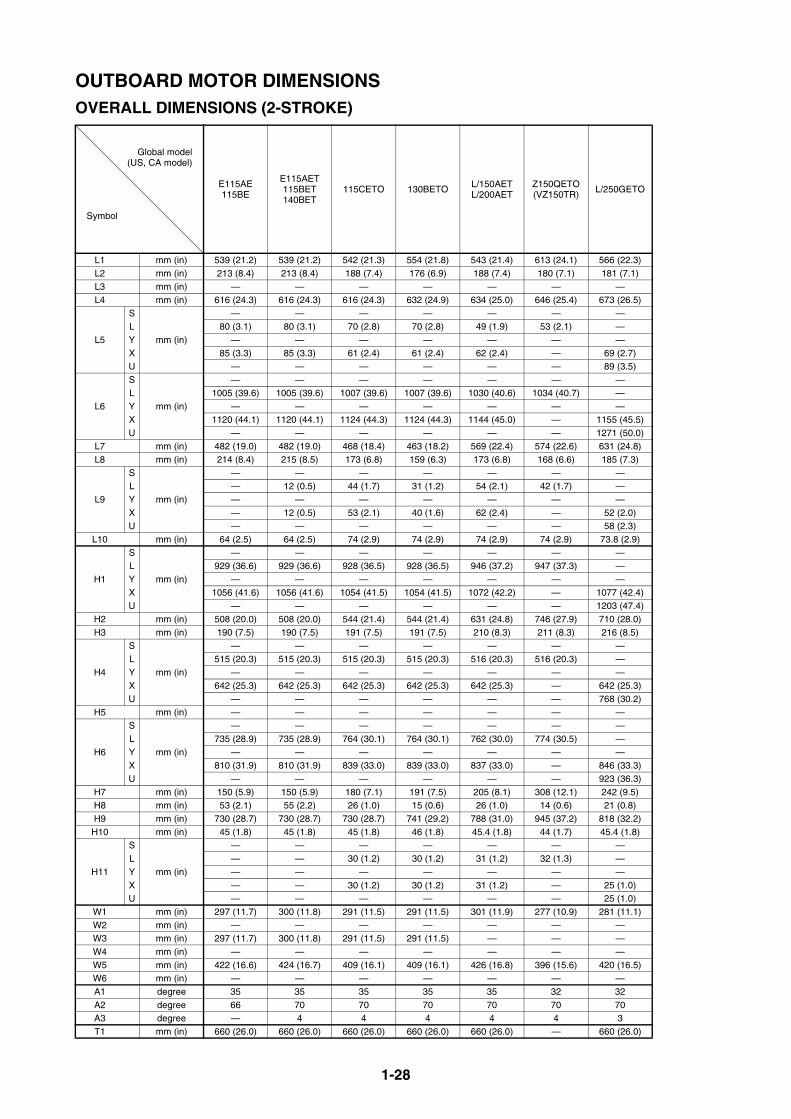
OUTBOARD MOTOR DIMENSIONSOVERALL DIMENSIONS (2-STROKE)
Global model(US, CA model)
Symbol
E115AE115BE
E115AET115BET140BET
115CETO 130BETO L/150AETL/200AET
Z150QETO(VZ150TR)
L/250GETO
L1 mm (in) 539 (21.2) 539 (21.2) 542 (21.3) 554 (21.8) 543 (21.4) 613 (24.1) 566 (22.3)L2 mm (in) 213 (8.4) 213 (8.4) 188 (7.4) 176 (6.9) 188 (7.4) 180 (7.1) 181 (7.1)L3 mm (in) — — — — — — —L4 mm (in) 616 (24.3) 616 (24.3) 616 (24.3) 632 (24.9) 634 (25.0) 646 (25.4) 673 (26.5)
L5
S
mm (in)
— — — — — — —L 80 (3.1) 80 (3.1) 70 (2.8) 70 (2.8) 49 (1.9) 53 (2.1) —Y — — — — — — —X 85 (3.3) 85 (3.3) 61 (2.4) 61 (2.4) 62 (2.4) — 69 (2.7)U — — — — — — 89 (3.5)
L6
S
mm (in)
— — — — — — —L 1005 (39.6) 1005 (39.6) 1007 (39.6) 1007 (39.6) 1030 (40.6) 1034 (40.7) —Y — — — — — — —X 1120 (44.1) 1120 (44.1) 1124 (44.3) 1124 (44.3) 1144 (45.0) — 1155 (45.5)U — — — — — — 1271 (50.0)
L7 mm (in) 482 (19.0) 482 (19.0) 468 (18.4) 463 (18.2) 569 (22.4) 574 (22.6) 631 (24.8)L8 mm (in) 214 (8.4) 215 (8.5) 173 (6.8) 159 (6.3) 173 (6.8) 168 (6.6) 185 (7.3)
L9
S
mm (in)
— — — — — — —L — 12 (0.5) 44 (1.7) 31 (1.2) 54 (2.1) 42 (1.7) —Y — — — — — — —X — 12 (0.5) 53 (2.1) 40 (1.6) 62 (2.4) — 52 (2.0)U — — — — — — 58 (2.3)
L10 mm (in) 64 (2.5) 64 (2.5) 74 (2.9) 74 (2.9) 74 (2.9) 74 (2.9) 73.8 (2.9)
H1
S
mm (in)
— — — — — — —L 929 (36.6) 929 (36.6) 928 (36.5) 928 (36.5) 946 (37.2) 947 (37.3) —Y — — — — — — —X 1056 (41.6) 1056 (41.6) 1054 (41.5) 1054 (41.5) 1072 (42.2) — 1077 (42.4)U — — — — — — 1203 (47.4)
H2 mm (in) 508 (20.0) 508 (20.0) 544 (21.4) 544 (21.4) 631 (24.8) 746 (27.9) 710 (28.0)H3 mm (in) 190 (7.5) 190 (7.5) 191 (7.5) 191 (7.5) 210 (8.3) 211 (8.3) 216 (8.5)
H4
S
mm (in)
— — — — — — —L 515 (20.3) 515 (20.3) 515 (20.3) 515 (20.3) 516 (20.3) 516 (20.3) —Y — — — — — — —X 642 (25.3) 642 (25.3) 642 (25.3) 642 (25.3) 642 (25.3) — 642 (25.3)U — — — — — — 768 (30.2)
H5 mm (in) — — — — — — —
H6
S
mm (in)
— — — — — — —L 735 (28.9) 735 (28.9) 764 (30.1) 764 (30.1) 762 (30.0) 774 (30.5) —Y — — — — — — —X 810 (31.9) 810 (31.9) 839 (33.0) 839 (33.0) 837 (33.0) — 846 (33.3)U — — — — — — 923 (36.3)
H7 mm (in) 150 (5.9) 150 (5.9) 180 (7.1) 191 (7.5) 205 (8.1) 308 (12.1) 242 (9.5)H8 mm (in) 53 (2.1) 55 (2.2) 26 (1.0) 15 (0.6) 26 (1.0) 14 (0.6) 21 (0.8)H9 mm (in) 730 (28.7) 730 (28.7) 730 (28.7) 741 (29.2) 788 (31.0) 945 (37.2) 818 (32.2)
H10 mm (in) 45 (1.8) 45 (1.8) 45 (1.8) 46 (1.8) 45.4 (1.8) 44 (1.7) 45.4 (1.8)
H11
S
mm (in)
— — — — — — —L — — 30 (1.2) 30 (1.2) 31 (1.2) 32 (1.3) —Y — — — — — — —X — — 30 (1.2) 30 (1.2) 31 (1.2) — 25 (1.0)U — — — — — — 25 (1.0)
W1 mm (in) 297 (11.7) 300 (11.8) 291 (11.5) 291 (11.5) 301 (11.9) 277 (10.9) 281 (11.1)W2 mm (in) — — — — — — —W3 mm (in) 297 (11.7) 300 (11.8) 291 (11.5) 291 (11.5) — — —W4 mm (in) — — — — — — —W5 mm (in) 422 (16.6) 424 (16.7) 409 (16.1) 409 (16.1) 426 (16.8) 396 (15.6) 420 (16.5)W6 mm (in) — — — — — — —A1 degree 35 35 35 35 35 32 32A2 degree 66 70 70 70 70 70 70A3 degree — 4 4 4 4 4 3T1 mm (in) 660 (26.0) 660 (26.0) 660 (26.0) 660 (26.0) 660 (26.0) — 660 (26.0)
1-29
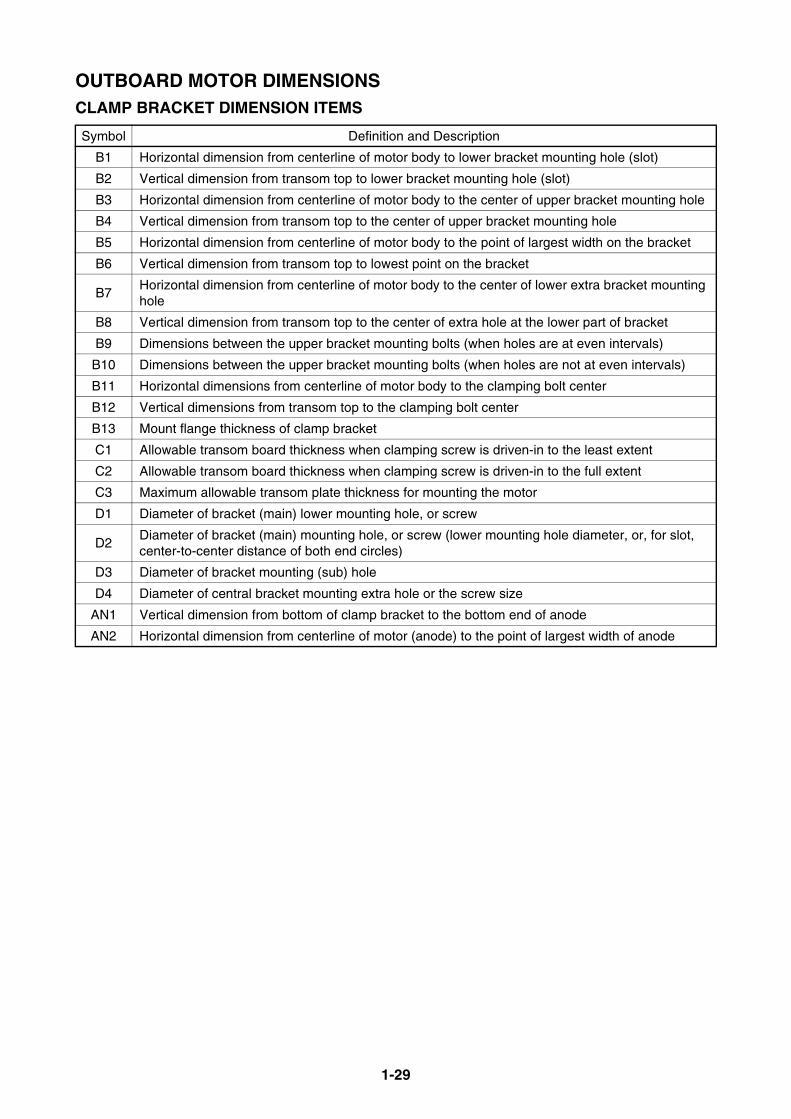
OUTBOARD MOTOR DIMENSIONSCLAMP BRACKET DIMENSION ITEMS
Symbol Definition and Description
B1 Horizontal dimension from centerline of motor body to lower bracket mounting hole (slot)
B2 Vertical dimension from transom top to lower bracket mounting hole (slot)
B3 Horizontal dimension from centerline of motor body to the center of upper bracket mounting hole
B4 Vertical dimension from transom top to the center of upper bracket mounting hole
B5 Horizontal dimension from centerline of motor body to the point of largest width on the bracket
B6 Vertical dimension from transom top to lowest point on the bracket
B7Horizontal dimension from centerline of motor body to the center of lower extra bracket mounting hole
B8 Vertical dimension from transom top to the center of extra hole at the lower part of bracket
B9 Dimensions between the upper bracket mounting bolts (when holes are at even intervals)
B10 Dimensions between the upper bracket mounting bolts (when holes are not at even intervals)
B11 Horizontal dimensions from centerline of motor body to the clamping bolt center
B12 Vertical dimensions from transom top to the clamping bolt center
B13 Mount flange thickness of clamp bracket
C1 Allowable transom board thickness when clamping screw is driven-in to the least extent
C2 Allowable transom board thickness when clamping screw is driven-in to the full extent
C3 Maximum allowable transom plate thickness for mounting the motor
D1 Diameter of bracket (main) lower mounting hole, or screw
D2Diameter of bracket (main) mounting hole, or screw (lower mounting hole diameter, or, for slot, center-to-center distance of both end circles)
D3 Diameter of bracket mounting (sub) hole
D4 Diameter of central bracket mounting extra hole or the screw size
AN1 Vertical dimension from bottom of clamp bracket to the bottom end of anode
AN2 Horizontal dimension from centerline of motor (anode) to the point of largest width of anode
1-30
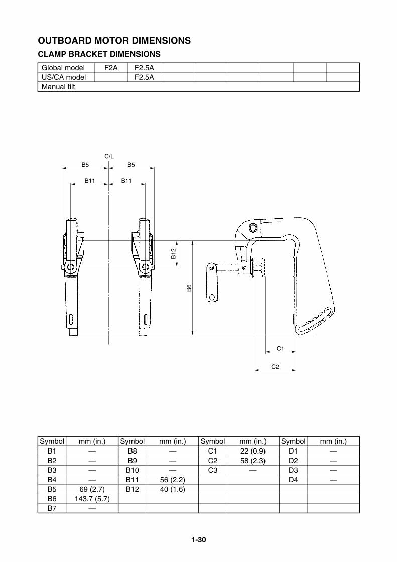
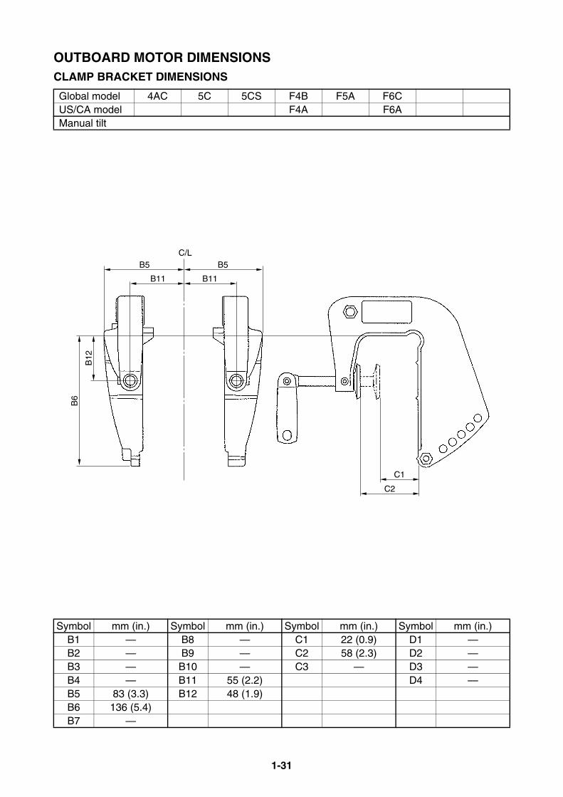
OUTBOARD MOTOR DIMENSIONSCLAMP BRACKET DIMENSIONS
Global model F2A F2.5AUS/CA model F2.5AManual tilt
Symbol mm (in.) Symbol mm (in.) Symbol mm (in.) Symbol mm (in.)B1 — B8 — C1 22 (0.9) D1 —B2 — B9 — C2 58 (2.3) D2 —B3 — B10 — C3 — D3 —B4 — B11 56 (2.2) D4 —B5 69 (2.7) B12 40 (1.6)B6 143.7 (5.7)B7 —
B6
B12
B5C/L
B5
B11B11
C1
C2
1-31
OUTBOARD MOTOR DIMENSIONSCLAMP BRACKET DIMENSIONS
Global model 4AC 5C 5CS F4B F5A F6CUS/CA model F4A F6AManual tilt
Symbol mm (in.) Symbol mm (in.) Symbol mm (in.) Symbol mm (in.)B1 — B8 — C1 22 (0.9) D1 —B2 — B9 — C2 58 (2.3) D2 —B3 — B10 — C3 — D3 —B4 — B11 55 (2.2) D4 —B5 83 (3.3) B12 48 (1.9)B6 136 (5.4)B7 —
B12
B6
B5C/L
B5
B11B11
C1
C2

1-32
OUTBOARD MOTOR DIMENSIONSCLAMP BRACKET DIMENSIONS
Global model 6C 8CUS/CA modelManual tilt
Symbol mm (in.) Symbol mm (in.) Symbol mm (in.) Symbol mm (in.)B1 — B8 — C1 22 (0.9) D1 —B2 — B9 — C2 55 (2.2) D2 —B3 — B10 — C3 — D3 —B4 — B11 56 (2.2) D4 —B5 75 (3.0) B12 50 (2.0)B6 164.3 (6.5)B7 —
C/L
B11B11
B5 B5
B12
B6
C1
C2
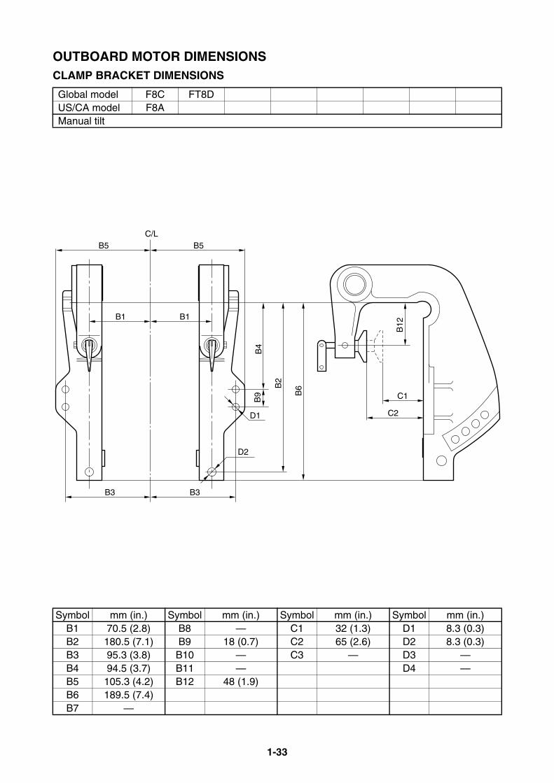
1-33
OUTBOARD MOTOR DIMENSIONSCLAMP BRACKET DIMENSIONS
Global model F8C FT8DUS/CA model F8AManual tilt
Symbol mm (in.) Symbol mm (in.) Symbol mm (in.) Symbol mm (in.)B1 70.5 (2.8) B8 — C1 32 (1.3) D1 8.3 (0.3)B2 180.5 (7.1) B9 18 (0.7) C2 65 (2.6) D2 8.3 (0.3)B3 95.3 (3.8) B10 — C3 — D3 —B4 94.5 (3.7) B11 — D4 —B5 105.3 (4.2) B12 48 (1.9)B6 189.5 (7.4)B7 —
B6B
2
B9
B4
B1B1
B5C/L
B5
D2
D1
B3B3
C1B
12
C2

1-34
OUTBOARD MOTOR DIMENSIONSCLAMP BRACKET DIMENSIONS
Global model 9.9F 15FUS/CA modelManual tilt
Symbol mm (in.) Symbol mm (in.) Symbol mm (in.) Symbol mm (in.)B1 92.5 (3.6) B8 — C1 30 (1.2) D1 8.3 (0.3)B2 103.5 (4.1) B9 54.5 (2.1) C2 56 (2.2) D2 8.3 (0.3)B3 92.5 (3.6) B10 — C3 — D3 —B4 49 (1.9) B11 70.5 (2.8) D4 —B5 102.5 (4.0) B12 69 (2.7)B6 176 (6.9)B7 —
B6
B2
B9
B12
B1
B11
B3
B5
B1
B11
B3
B5B
4
C1
C2
D2
D1
C/L
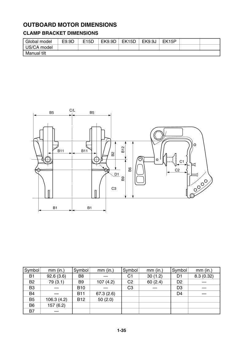
1-35
OUTBOARD MOTOR DIMENSIONSCLAMP BRACKET DIMENSIONS
Global model E9.9D E15D EK9.9D EK15D EK9.9J EK15PUS/CA modelManual tilt
Symbol mm (in.) Symbol mm (in.) Symbol mm (in.) Symbol mm (in.)B1 92.6 (3.6) B8 — C1 30 (1.2) D1 8.3 (0.32)B2 79 (3.1) B9 107 (4.2) C2 60 (2.4) D2 —B3 — B10 — C3 — D3 —B4 — B11 67.3 (2.6) D4 —B5 106.3 (4.2) B12 50 (2.0)B6 157 (6.2)B7 —
B5C/L
B2B11B11 B
12B
9
B1B1
B5
D1
C3
C1
C2B6
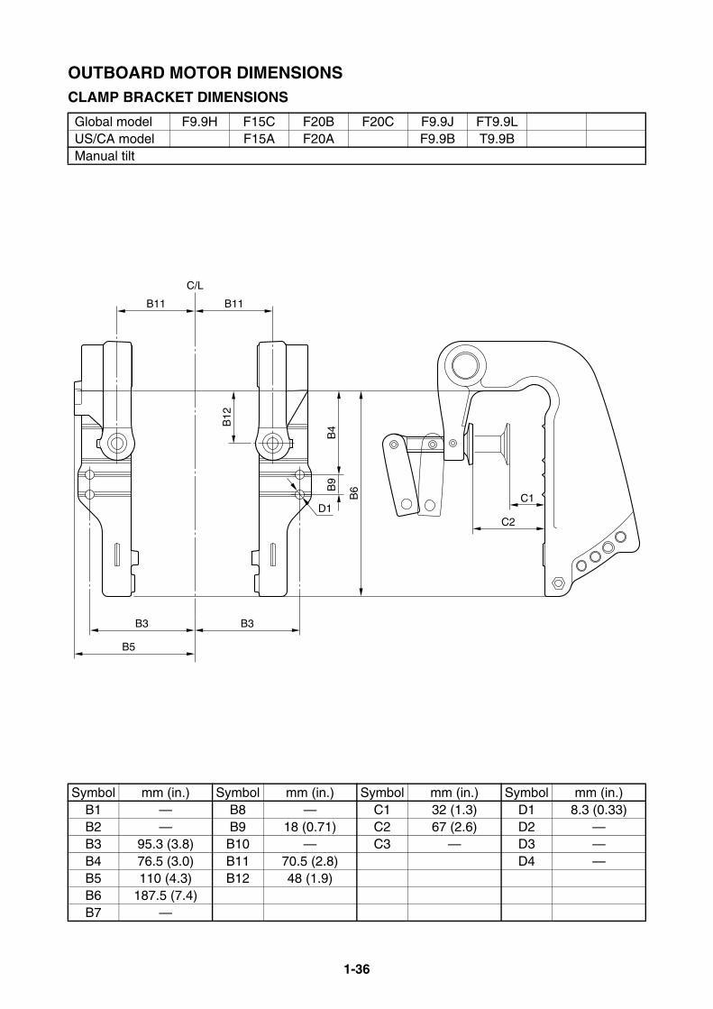
1-36
OUTBOARD MOTOR DIMENSIONSCLAMP BRACKET DIMENSIONS
Global model F9.9H F15C F20B F20C F9.9J FT9.9LUS/CA model F15A F20A F9.9B T9.9BManual tilt
Symbol mm (in.) Symbol mm (in.) Symbol mm (in.) Symbol mm (in.)B1 — B8 — C1 32 (1.3) D1 8.3 (0.33)B2 — B9 18 (0.71) C2 67 (2.6) D2 —B3 95.3 (3.8) B10 — C3 — D3 —B4 76.5 (3.0) B11 70.5 (2.8) D4 —B5 110 (4.3) B12 48 (1.9)B6 187.5 (7.4)B7 —
C/L
B3
B11
B6
B4B
12
B5
B3
B11
B9
C1
C2D1
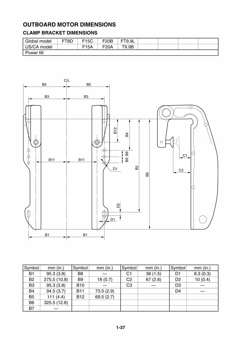
1-37
OUTBOARD MOTOR DIMENSIONSCLAMP BRACKET DIMENSIONS
Global model FT8D F15C F20B FT9.9LUS/CA model F15A F20A T9.9BPower tilt
Symbol mm (in.) Symbol mm (in.) Symbol mm (in.) Symbol mm (in.)B1 95.3 (3.8) B8 — C1 38 (1.5) D1 8.3 (0.3)B2 275.5 (10.8) B9 18 (0.7) C2 67 (2.6) D2 10 (0.4)B3 95.3 (3.8) B10 — C3 — D3 —B4 94.5 (3.7) B11 73.5 (2.9) D4 —B5 111 (4.4) B12 69.5 (2.7)B6 325.5 (12.8)B7 —
C1
C2
B11
B1
D2
D1
D1
B9
B9
B3
B12
B4
B2
B6
B5
B11
B1
B3
B5C/L
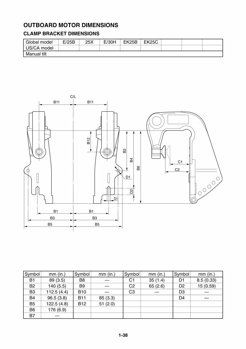
1-38
OUTBOARD MOTOR DIMENSIONSCLAMP BRACKET DIMENSIONS
Global model E/25B 25X E/30H EK25B EK25CUS/CA modelManual tilt
Symbol mm (in.) Symbol mm (in.) Symbol mm (in.) Symbol mm (in.)B1 89 (3.5) B8 — C1 35 (1.4) D1 8.5 (0.33)B2 140 (5.5) B9 — C2 65 (2.6) D2 15 (0.59)B3 112.5 (4.4) B10 — C3 — D3 —B4 96.5 (3.8) B11 85 (3.3) D4 —B5 122.5 (4.8) B12 51 (2.0)B6 176 (6.9)B7 —
B11
C/L
B3
B1
B5
C2
B2
B12
B4
D2
B6
C1
D1
B11
B3
B1
B5
D1
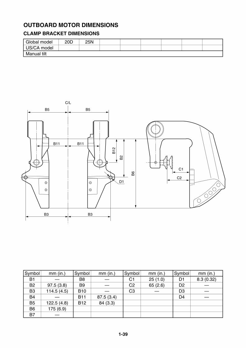
1-39
OUTBOARD MOTOR DIMENSIONSCLAMP BRACKET DIMENSIONS
Global model 20D 25NUS/CA modelManual tilt
Symbol mm (in.) Symbol mm (in.) Symbol mm (in.) Symbol mm (in.)B1 — B8 — C1 25 (1.0) D1 8.3 (0.32)B2 97.5 (3.8) B9 — C2 65 (2.6) D2 —B3 114.5 (4.5) B10 — C3 — D3 —B4 — B11 87.5 (3.4) D4 —B5 122.5 (4.8) B12 84 (3.3)B6 175 (6.9)B7 —
B5
C/L
B5
B11B11
B2
B3B3
B12
C1
C2D1
B6
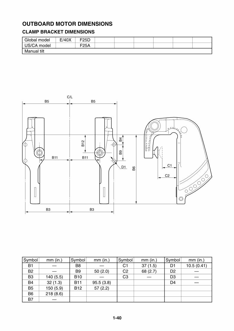
1-40
OUTBOARD MOTOR DIMENSIONSCLAMP BRACKET DIMENSIONS
Global model E/40X F25DUS/CA model F25AManual tilt
Symbol mm (in.) Symbol mm (in.) Symbol mm (in.) Symbol mm (in.)B1 — B8 — C1 37 (1.5) D1 10.5 (0.41)B2 — B9 50 (2.0) C2 68 (2.7) D2 —B3 140 (5.5) B10 — C3 — D3 —B4 32 (1.3) B11 95.5 (3.8) D4 —B5 150 (5.9) B12 57 (2.2)B6 218 (8.6)B7 —
C2
C1
B6
B9
B3
B11
B5C/L
B4
B12
D1
B3
B11
B5
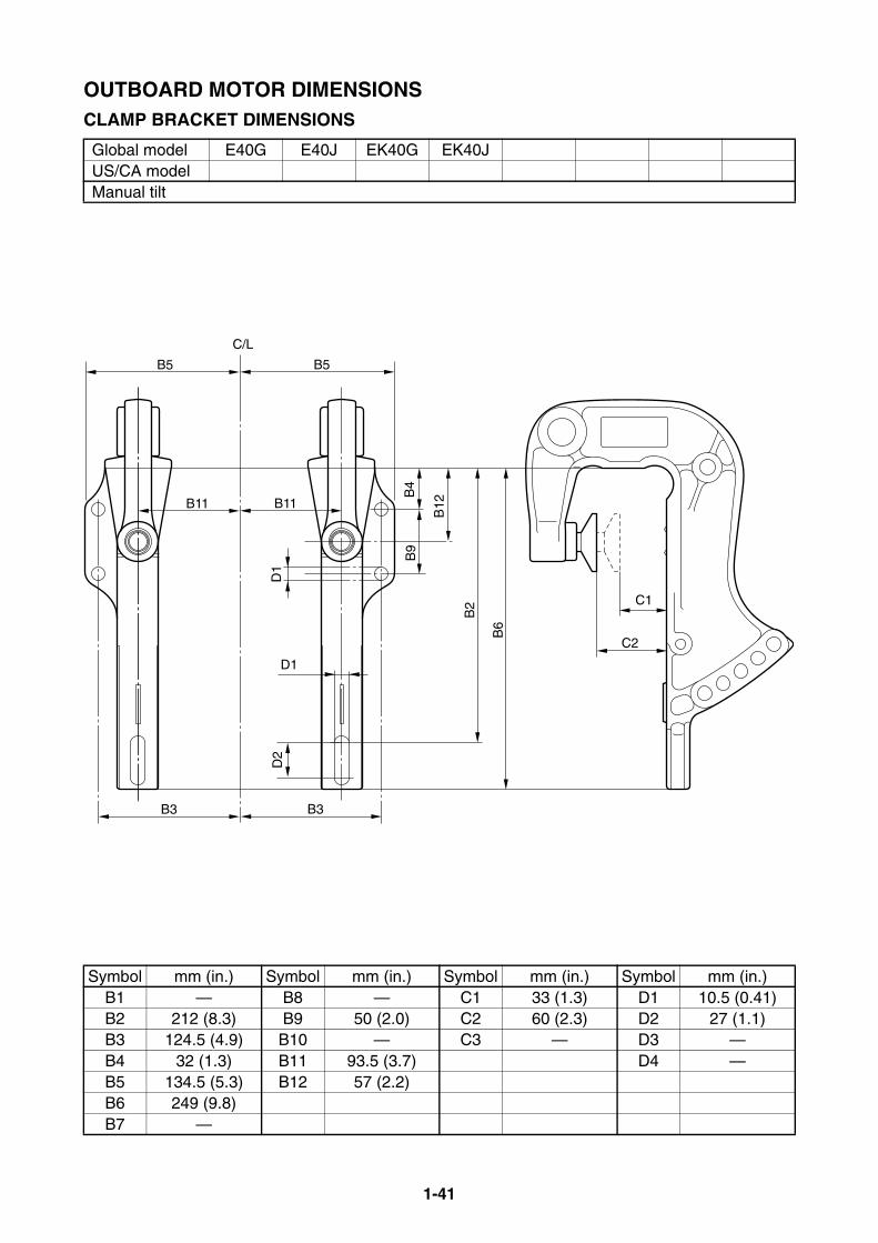
1-41
OUTBOARD MOTOR DIMENSIONSCLAMP BRACKET DIMENSIONS
Global model E40G E40J EK40G EK40JUS/CA modelManual tilt
Symbol mm (in.) Symbol mm (in.) Symbol mm (in.) Symbol mm (in.)B1 — B8 — C1 33 (1.3) D1 10.5 (0.41)B2 212 (8.3) B9 50 (2.0) C2 60 (2.3) D2 27 (1.1)B3 124.5 (4.9) B10 — C3 — D3 —B4 32 (1.3) B11 93.5 (3.7) D4 —B5 134.5 (5.3) B12 57 (2.2)B6 249 (9.8)B7 —
C2
C1
B3
D2
D1
B11
B5
C/L
B2
B6
B12
B9
B4
B3
B11
B5
D1
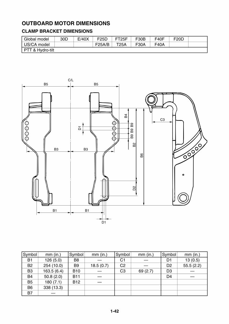
1-42
OUTBOARD MOTOR DIMENSIONSCLAMP BRACKET DIMENSIONS
Global model 30D E/40X F25D FT25F F30B F40F F20DUS/CA model F25A/B T25A F30A F40APTT & Hydro-tilt
Symbol mm (in.) Symbol mm (in.) Symbol mm (in.) Symbol mm (in.)B1 126 (5.0) B8 — C1 — D1 13 (0.5)B2 254 (10.0) B9 18.5 (0.7) C2 — D2 55.5 (2.2)B3 163.5 (6.4) B10 — C3 69 (2.7) D3 —B4 50.8 (2.0) B11 — D4 —B5 180 (7.1) B12 —B6 338 (13.3)B7 —
C3
B3
B5C/L
B1
B4
B9
B2
D2
B6
B9
B9
D1
D1
B3
B5
B1
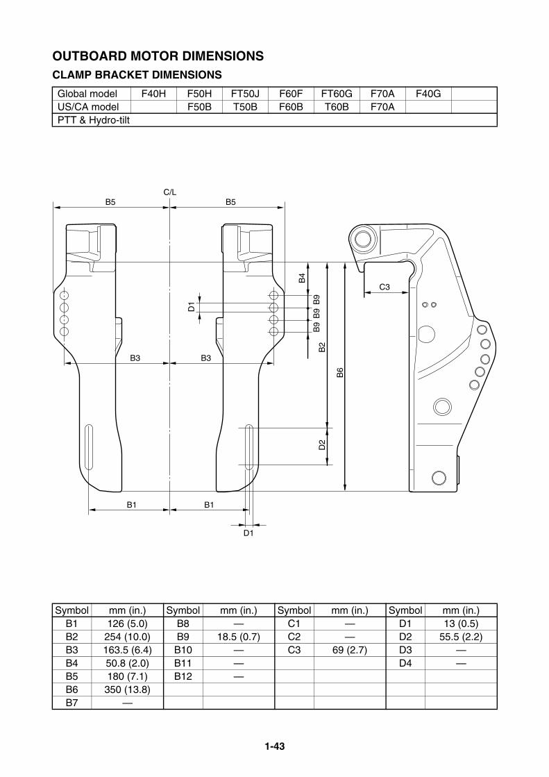
1-43
OUTBOARD MOTOR DIMENSIONSCLAMP BRACKET DIMENSIONS
Global model F40H F50H FT50J F60F FT60G F70A F40GUS/CA model F50B T50B F60B T60B F70APTT & Hydro-tilt
Symbol mm (in.) Symbol mm (in.) Symbol mm (in.) Symbol mm (in.)B1 126 (5.0) B8 — C1 — D1 13 (0.5)B2 254 (10.0) B9 18.5 (0.7) C2 — D2 55.5 (2.2)B3 163.5 (6.4) B10 — C3 69 (2.7) D3 —B4 50.8 (2.0) B11 — D4 —B5 180 (7.1) B12 —B6 350 (13.8)B7 —
C3
B3
B5C/L
B1
B4
B9
B2
D2
B6
B9
B9
D1
D1
B3
B5
B1

1-44
OUTBOARD MOTOR DIMENSIONSCLAMP BRACKET DIMENSIONS
Global model 40V 50H E60H F50D FT50CUS/CA modelPTT & Hydro-tilt
Symbol mm (in.) Symbol mm (in.) Symbol mm (in.) Symbol mm (in.)B1 126 (5.0) B8 203 (8.0) C1 — D1 13 (0.51)B2 254 (10.0) B9 18.5 (0.73) C2 — D2 60.5 (2.4)B3 163.5 (6.4) B10 — C3 69 (2.7) D3 13 (0.51)B4 50.8 (2.0) B11 — D4 —B5 180 (7.1) B12 —B6 355 (14.0)B7 138 (5.4)
B5B
6
B2
B9
B9
B9
D2
B7
B1
D1
B4
C3
D1
B3
B5
C/L
B7
B1
B3
D3
B8
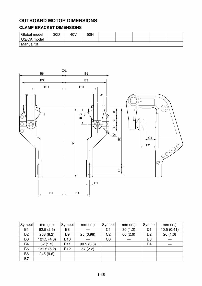
1-45
OUTBOARD MOTOR DIMENSIONSCLAMP BRACKET DIMENSIONS
Global model 30D 40V 50HUS/CA modelManual tilt
Symbol mm (in.) Symbol mm (in.) Symbol mm (in.) Symbol mm (in.)B1 62.5 (2.5) B8 — C1 30 (1.2) D1 10.5 (0.41)B2 208 (8.2) B9 25 (0.98) C2 66 (2.6) D2 26 (1.0)B3 121.5 (4.8) B10 — C3 — D3 —B4 32 (1.3) B11 90.5 (3.6) D4 —B5 131.5 (5.2) B12 57 (2.2)B6 245 (9.6)B7 —
B3
B11
B5C/L
B6
B12
D2
B2
B4
B9
B9
D1
D1
B1
B3
B11
B5
B1
C1
C2
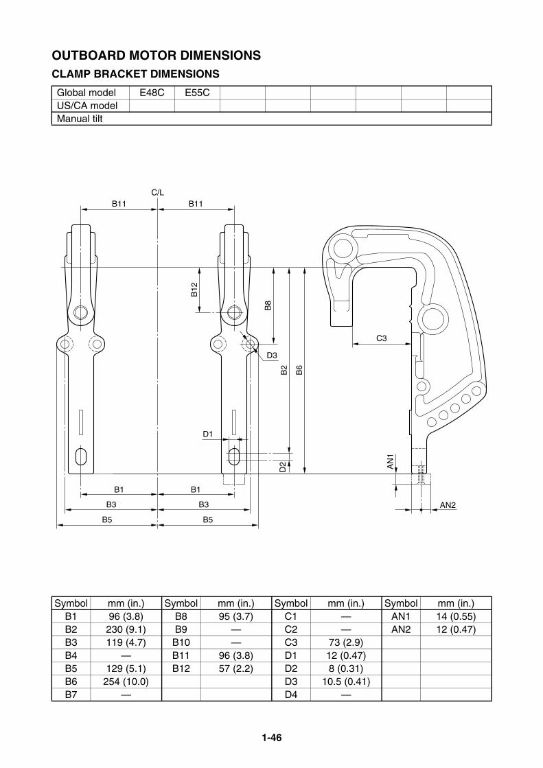
1-46
OUTBOARD MOTOR DIMENSIONSCLAMP BRACKET DIMENSIONS
Global model E48C E55CUS/CA modelManual tilt
Symbol mm (in.) Symbol mm (in.) Symbol mm (in.) Symbol mm (in.)B1 96 (3.8) B8 95 (3.7) C1 — AN1 14 (0.55)B2 230 (9.1) B9 — C2 — AN2 12 (0.47)B3 119 (4.7) B10 — C3 73 (2.9)B4 — B11 96 (3.8) D1 12 (0.47)B5 129 (5.1) B12 57 (2.2) D2 8 (0.31)B6 254 (10.0) D3 10.5 (0.41)B7 — D4 —
B11C/L
B3
B1
B5
B11
B2
B6
B8
B12
D3
B3
B1
B5
D2
D1
C3
AN
1
AN2
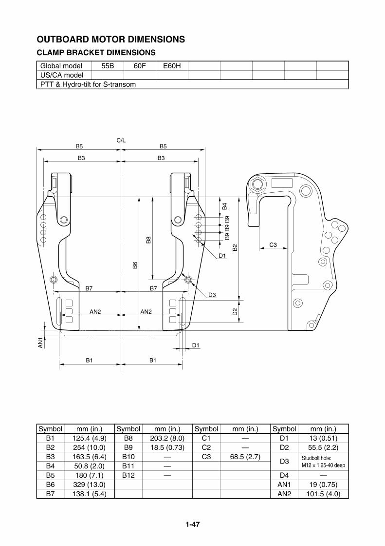
1-47
OUTBOARD MOTOR DIMENSIONSCLAMP BRACKET DIMENSIONS
Global model 55B 60F E60HUS/CA modelPTT & Hydro-tilt for S-transom
Symbol mm (in.) Symbol mm (in.) Symbol mm (in.) Symbol mm (in.)B1 125.4 (4.9) B8 203.2 (8.0) C1 — D1 13 (0.51)B2 254 (10.0) B9 18.5 (0.73) C2 — D2 55.5 (2.2)B3 163.5 (6.4) B10 — C3 68.5 (2.7)
D3 Studbolt hole: M12 × 1.25-40 deepB4 50.8 (2.0) B11 —
B5 180 (7.1) B12 — D4 —B6 329 (13.0) AN1 19 (0.75)B7 138.1 (5.4) AN2 101.5 (4.0)
B6
B8
B1
B7
D1
B3
B5C/L
B2
D2
C3
D1
B4
B9
B9
B9
B1
B7
B3
B5
D3
AN
1
AN2 AN2
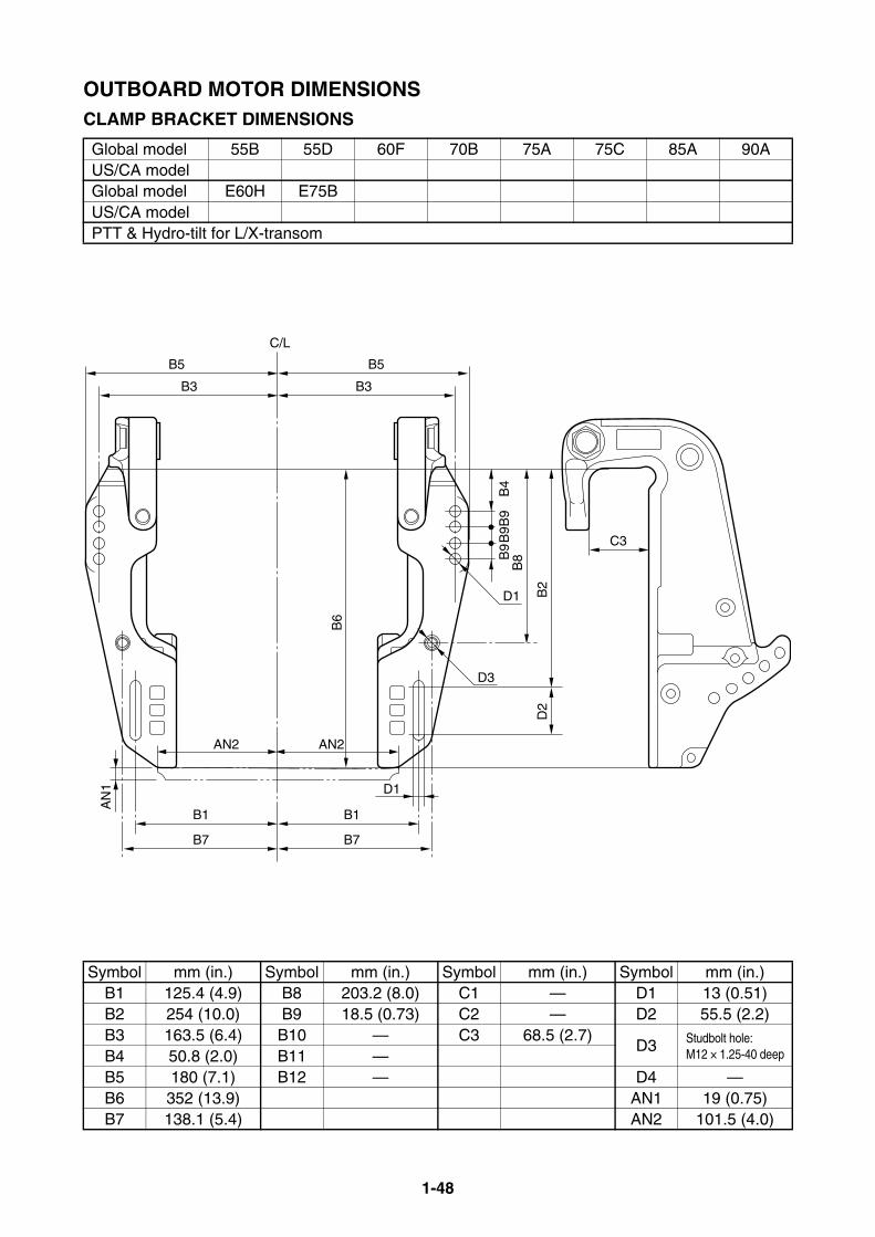
1-48
OUTBOARD MOTOR DIMENSIONSCLAMP BRACKET DIMENSIONS
Global model 55B 55D 60F 70B 75A 75C 85A 90AUS/CA modelGlobal model E60H E75BUS/CA modelPTT & Hydro-tilt for L/X-transom
Symbol mm (in.) Symbol mm (in.) Symbol mm (in.) Symbol mm (in.)B1 125.4 (4.9) B8 203.2 (8.0) C1 — D1 13 (0.51)B2 254 (10.0) B9 18.5 (0.73) C2 — D2 55.5 (2.2)B3 163.5 (6.4) B10 — C3 68.5 (2.7)
D3 Studbolt hole: M12 × 1.25-40 deepB4 50.8 (2.0) B11 —
B5 180 (7.1) B12 — D4 —B6 352 (13.9) AN1 19 (0.75)B7 138.1 (5.4) AN2 101.5 (4.0)
B6
B1
B7
D1
B3
B5
C/L
B2
B8
D2
C3
D1
B4
B9
B9
B9
B1
B7
B3
B5
D3
AN
1
AN2 AN2

1-49
OUTBOARD MOTOR DIMENSIONSCLAMP BRACKET DIMENSIONS
Global model F75B F80B F90B F100DUS/CA model F75A F90APTT
Symbol mm (in.) Symbol mm (in.) Symbol mm (in.) Symbol mm (in.)B1 125.4 (4.9) B8 — C1 — AN1 19 (0.75)B2 254 (10.0) B9 18.5 (0.73) C2 — AN2 101.5 (4.0)B3 163.5 (6.4) B10 — C3 80 (3.1)B4 50.8 (2.0) B11 — D1 13 (0.51)B5 180 (7.1) B12 — D2 55.5 (2.2)B6 368 (14.5) B13 20 (0.79) D3 —B7 — D4 —
B6
B3
B1
D1
B5C/L
B3
B1
B5
C3
B13
B2
D2
D1
B4
B9
B9
B9
AN
1
AN2 AN2

1-50
OUTBOARD MOTOR DIMENSIONSCLAMP BRACKET DIMENSIONS
Global model E115A 115B 115C 130B 140B L/150A 150G Z150QUS/CA model VZ150Global model L/200A F75C F95A F100B F/FL115AUS/CA model F/LF115AGlobal model F/FL150A F/FL150B F225CUS/CA/ANZ model F/LF150APTT & Hydro tilt
Symbol mm (in.) Symbol mm (in.) Symbol mm (in.) Symbol mm (in.)B1 125.4 (4.9) B8 — C1 — AN1 52 (2.0)B2 254 (10.0) B9 18.5 (0.73) C2 — AN2 102 (4.0)B3 163.5 (6.4) B10 — C3 82 (3.2)B4 50.8 (2.0) B11 — D1 13 (0.51)B5 180 (7.1) B12 — D2 55.5 (2.2)B6 367 (14.4) B13 24 (0.94) D3 —B7 — D4 —
B13
B5C/L
B3B3
B6
B1
B2
D1
C3
D1
D2
B4
B9
B9
B9
B5
B1
AN
1
AN2 AN2
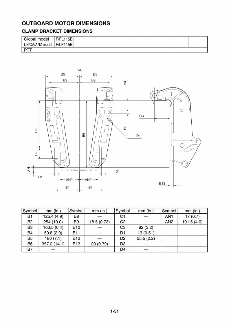
1-51
OUTBOARD MOTOR DIMENSIONSCLAMP BRACKET DIMENSIONS
Global model F/FL115BUS/CA/ANZ model F/LF115BPTT
Symbol mm (in.) Symbol mm (in.) Symbol mm (in.) Symbol mm (in.)B1 125.4 (4.9) B8 — C1 — AN1 17 (0.7)B2 254 (10.0) B9 18.5 (0.73) C2 — AN2 101.5 (4.0)B3 163.5 (6.4) B10 — C3 82 (3.2)B4 50.8 (2.0) B11 — D1 13 (0.51)B5 180 (7.1) B12 — D2 55.5 (2.2)B6 357.2 (14.1) B13 20 (0.79) D3 —B7 — D4 —
D2
AN
1
B2
B5B5
B3 B3
C3
D1
B1
AN2 AN2
B1
D1
D1
B9
B4
B6
C/L
B13
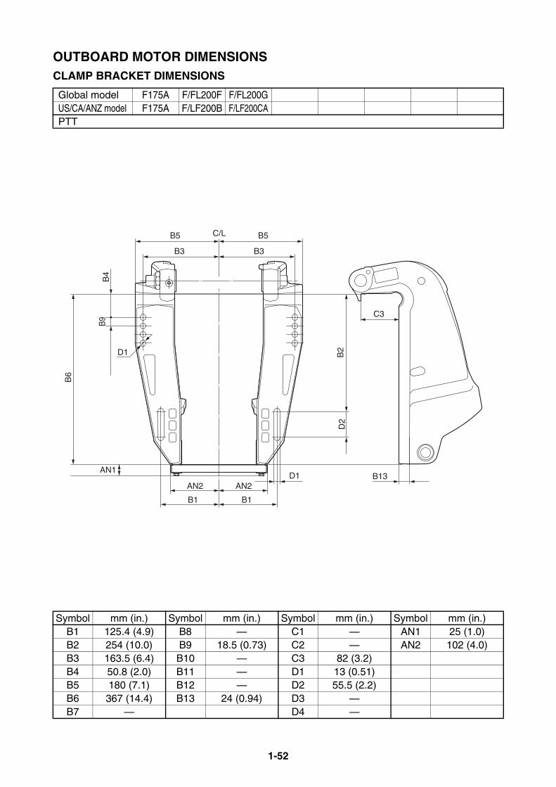
1-52
OUTBOARD MOTOR DIMENSIONSCLAMP BRACKET DIMENSIONS
Global model F175A F/FL200F F/FL200GUS/CA/ANZ model F175A F/LF200B F/LF200CAPTT
Symbol mm (in.) Symbol mm (in.) Symbol mm (in.) Symbol mm (in.)B1 125.4 (4.9) B8 — C1 — AN1 25 (1.0)B2 254 (10.0) B9 18.5 (0.73) C2 — AN2 102 (4.0)B3 163.5 (6.4) B10 — C3 82 (3.2)B4 50.8 (2.0) B11 — D1 13 (0.51)B5 180 (7.1) B12 — D2 55.5 (2.2)B6 367 (14.4) B13 24 (0.94) D3 —B7 — D4 —
C/LB5 B5
B3 B3
D1
B1 B1
AN2 AN2D1
D2
B2
C3
B13
B4
AN1
B6
B9
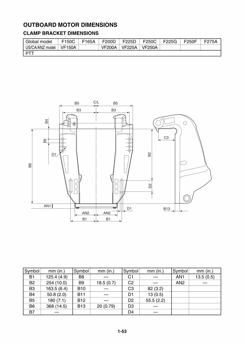
1-53
OUTBOARD MOTOR DIMENSIONSCLAMP BRACKET DIMENSIONS
Global model F150C F165A F200D F225D F250C F225G F250F F275AUS/CA/ANZ model VF150A VF200A VF225A VF250APTT
Symbol mm (in.) Symbol mm (in.) Symbol mm (in.) Symbol mm (in.)B1 125.4 (4.9) B8 — C1 — AN1 13.5 (0.5)B2 254 (10.0) B9 18.5 (0.7) C2 — AN2 —B3 163.5 (6.4) B10 — C3 82 (3.2)B4 50.8 (2.0) B11 — D1 13 (0.5)B5 180 (7.1) B12 — D2 55.5 (2.2)B6 368 (14.5) B13 20 (0.79) D3 —B7 — D4 —
C/LB5 B5
B3 B3
D1
B1 B1
AN2 AN2D1
D2
B2
C3
B13
B4
AN1
B6
B9

1-54
OUTBOARD MOTOR DIMENSIONSCLAMP BRACKET DIMENSIONS
Global model L/250G F/FL200B F/FL200C F/FL225B F/FL250A F/FL250G F/FL225F F/FL250DUS/CA/ANZ model F/LF200A F/LF225A F/LF250A F/LF225CA F/LF250CAGlobal model F/FL300BUS/CA/ANZ model F/LF300CAPTT
Symbol mm (in.) Symbol mm (in.) Symbol mm (in.) Symbol mm (in.)B1 125.4 (4.9) B8 — C1 — AN1 52 (2.0)B2 254 (10.0) B9 18.5 (0.7) C2 — AN2 102 (4.0)B3 163.5 (6.4) B10 — C3 79 (3.1)B4 50.8 (2.0) B11 — D1 13 (0.5)B5 180 (7.1) B12 — D2 55.5 (2.2)B6 411 (16.2) B13 20 (0.79) D3 —B7 — D4 —
C/LB5 B5
B3 B3
B1
AN2 AN2
B1
D1
C3
B13
B4
D1
B9B
9B9
B2
D2
B6
AN
1
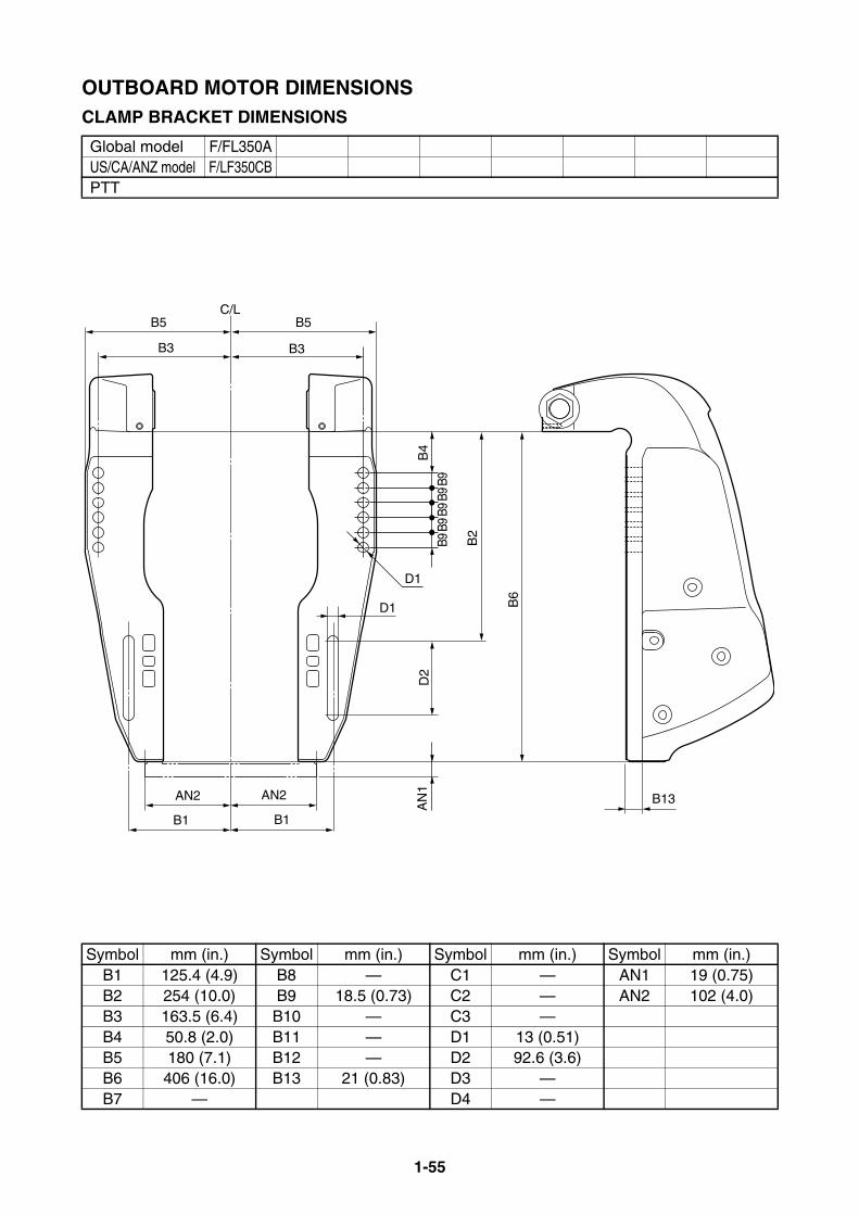
1-55
OUTBOARD MOTOR DIMENSIONSCLAMP BRACKET DIMENSIONS
Global model F/FL350AUS/CA/ANZ model F/LF350CBPTT
Symbol mm (in.) Symbol mm (in.) Symbol mm (in.) Symbol mm (in.)B1 125.4 (4.9) B8 — C1 — AN1 19 (0.75)B2 254 (10.0) B9 18.5 (0.73) C2 — AN2 102 (4.0)B3 163.5 (6.4) B10 — C3 —B4 50.8 (2.0) B11 — D1 13 (0.51)B5 180 (7.1) B12 — D2 92.6 (3.6)B6 406 (16.0) B13 21 (0.83) D3 —B7 — D4 —
B5
B3
B5
B3
B13
B2
B4
D1
B1 B1
C/L
B9
AN2 AN2
D2
AN
1
B6
D1
B9B9
B9B9

MEMO

2-1
PROPELLERS
PROPELLER SPECIFICATIONS ............................................................. 2-2PROPELLER TYPES ........................................................................... 2-2
PROPELLER IDENTIFICATION........................................................... 2-5
PROPELLER SELECTION....................................................................... 2-62014 PROPELLER APPLICATIONS........................................................ 2-6
STANDARD PROPELLER ................................................................... 2-6
STANDARD PROPELLERS (Shift Dampener System [SDS]) ........... 2-12
DUAL THRUST PROPELLERS.......................................................... 2-13
WEEDLESS PROPELLERS............................................................... 2-14
RELIANCE SERIES PROPELLERS (STD) ........................................ 2-14
RELIANCE SERIES PROPELLERS
(Shift Dampener System [SDS]) .................................................... 2-15
SALTWATER SERIES PROPELLERS............................................... 2-16
SALTWATER SERIES II PROPELLERS (STD)................................. 2-17
SALTWATER SERIES II PROPELLERS
(Shift Dampener System [SDS]) .................................................... 2-18
SALTWATER SERIES HS4 PROPELLERS (STD) ............................ 2-19
SALTWATER SERIES HS4 PROPELLERS
(Shift Dampener System [SDS]) .................................................... 2-19
SALTWATER SERIES XL PROPELLERS
(Shift Dampener System [SDS]) .................................................... 2-20
SALTWATER SERIES XL4 PROPELLERS
(Shift Dampener System [SDS]) .................................................... 2-20
VMAX SERIES PROPELLERS .......................................................... 2-21
PERFORMANCE SERIES PROPELLERS......................................... 2-21
HIGH PERFORMANCE SERIES PROPELLERS............................... 2-22
WOT OPERATION RANGE TABLE....................................................... 2-23

2-2
PROPELLER SPECIFICATIONSPROPELLER TYPESYamaha propellers are specifically designed tomatch the characteristics of Yamaha outboardmotors. There are some types of propellers for the bestmatching depending on the operating condi-tion. Major types of propellers include:
STANDARDThis propeller series is designed for generaluse to match a wide range of operating condi-tions.A stainless steel or an aluminum propeller canbe selected to suit the preference of the user.A stainless steel, counter rotation propeller isavailable for twin engine applications.The aluminum, regular rotation propeller withSDS (Shift Dampener System) is nowdesigned to match the K-series fitting boss.
RELIANCE SERIESNew polished stainless steel propellers aredesigned to provide for 150PS and biggerstandard type engines. These propellers are generally more aggres-sive than black standard stainless steel propel-lers, and will fit the engines under almost alloperating conditions. L/H rotation propellers are available for twin-engine applications.
SALTWATER SERIES IIThis new breed of stainless steel props isdesigned exclusively for offshore fishing boatsand features highly polished, larger diameterdesign. The aggressive rake angle and extracupping on the blades provide superior mid-range fuel efficiency, along with excellent anti-cavitation performance. Shift Dampener System (SDS) has beenadopted to reduce the shock and noise whenshifting, and become possible to replace thepropeller damper.L/H rotation propellers are available for twin-engine applications.
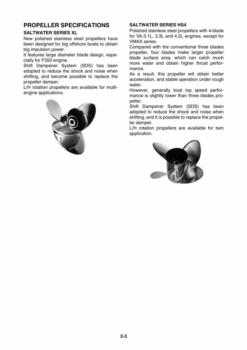
2-3
PROPELLER SPECIFICATIONSSALTWATER SERIES XLNew polished stainless steel propellers havebeen designed for big offshore boats to obtainbig impulsion power. It features large diameter blade design, espe-cially for F350 engine. Shift Dampener System (SDS) has beenadopted to reduce the shock and noise whenshifting, and become possible to replace thepropeller damper.L/H rotation propellers are available for multi-engine applications.
SALTWATER SERIES HS4Polished stainless steel propellers with 4-bladefor V6-3.1L, 3.3L and 4.2L engines, except forVMAX series.Compared with the conventional three bladespropeller, four blades make larger propellerblade surface area, which can catch muchmore water and obtain higher thrust perfor-mance.As a result, this propeller will obtain betteracceleration, and stable operation under roughwater.However, generally boat top speed perfor-mance is slightly lower than three blades pro-peller.Shift Dampener System (SDS) has beenadopted to reduce the shock and noise whenshifting, and it is possible to replace the propel-ler damper.L/H rotation propellers are available for twinapplication.

2-4
PROPELLER SPECIFICATIONSSALTWATER SERIES XL4Designed for the V8 F350 5.3L four strokeonly, this stainless steel four blade prop isintended for large offshore boats—such asexpress cruisers or walk arounds—that requiremassive thrust-to-plane and additional propel-ler grip for maximum operational efficiency.Made of highly polished stainless steel andavailable with our patent-pending Shift Damp-ener System (SDS).
* Shift Dampener System (SDS):Using a special new design and high-strengthcomponents, much of the resulting force of anoutboard shifting into forward or reverse gear isabsorbed, resulting in far quieter and smootheroperation.
VMAX SERIESThese polished stainless steel propellers aredesigned for a high-speed and light weightspecial boat with high-power engine for betterperformance. These specialized propellers are generally moreaggressive than the ventilated type propellers.
PERFORMANCEThese stainless steel propellers with vents forexhaust gas induction offer the best accelera-tion and top end performance causing theengine rpm rapidly increasing with a high rake,progressive pitch and more cup. It allows higher transom mounting such as bassboats, yet does not increase steering torque.
PROPELLER SPECIFICATIONSHIGH PERFORMANCEWith the progressive pitch design and highlycupped blades, these special small hub pro-pellers are designed for high-performance run-about boats. The through-hub exhaust system allows theexhaust gas to outlet the leading edge of eachblade for enhanced acceleration.
WEEDLESSThis is designed for use in shallow water.It eliminates weed buildup around the propellerhub.
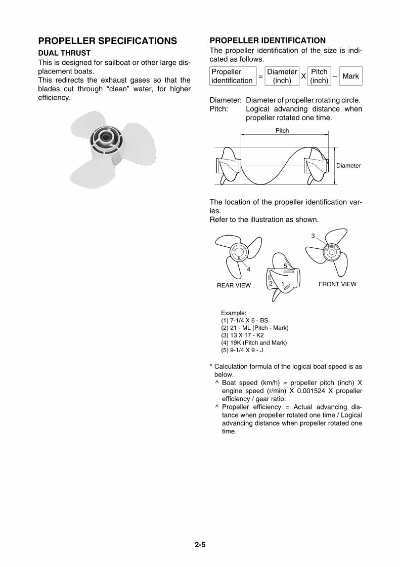
2-5
PROPELLER SPECIFICATIONSDUAL THRUSTThis is designed for sailboat or other large dis-placement boats. This redirects the exhaust gases so that theblades cut through “clean” water, for higherefficiency.
PROPELLER IDENTIFICATIONThe propeller identification of the size is indi-cated as follows.
Diameter: Diameter of propeller rotating circle. Pitch: Logical advancing distance when
propeller rotated one time.
The location of the propeller identification var-ies.Refer to the illustration as shown.
Example:(1) 7-1/4 X 6 - BS(2) 21 - ML (Pitch - Mark)(3) 13 X 17 - K2(4) 19K (Pitch and Mark)(5) 9-1/4 X 9 - J
* Calculation formula of the logical boat speed is asbelow.^ Boat speed (km/h) = propeller pitch (inch) X
engine speed (r/min) X 0.001524 X propellerefficiency / gear ratio.
^ Propeller efficiency = Actual advancing dis-tance when propeller rotated one time / Logicaladvancing distance when propeller rotated onetime.
Propeller identification
=Diameter
(inch)X
Pitch(inch)
– Mark
Pitch
Diameter
REAR VIEW
4
FRONT VIEW
3
2 1
5
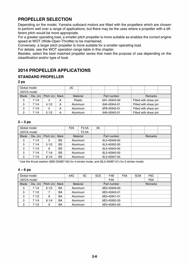
2-6
PROPELLER SELECTIONDepending on the model, Yamaha outboard motors are fitted with the propellers which are chosento perform well over a range of applications, but there may be the uses where a propeller with a dif-ferent pitch would be more appropriate.For a greater operating load, a smaller pitch propeller is more suitable as enables the correct enginespeed at WOT (Wide-Open-Throttle) to be maintained.Conversely, a larger pitch propeller is more suitable for a smaller operating load.For details, see the WOT operation range table in this chapter.Besides, select the best matched propeller series that meet the purpose of use depending on theclassification and/or type of boat.
2014 PROPELLER APPLICATIONSSTANDARD PROPELLER2 ps
2 – 3 ps
* Use the thrust washer (68D-G5987-00) for 4-stroke mode, and (6L5-45987-01) for 2-stroke model.
4 – 6 ps
Global model 2C
US/CA model
Blade Dia. (in) Pitch (in) Mark Material Part number Remarks3 7 1/4 4 A Plastic 6A1-45943-00 Fitted with shear pin
3 7 1/4 4 1/2 A Aluminum 646-45944-01 Fitted with shear pin
3 7 1/4 5 A Aluminum 6F8-45942-01 Fitted with shear pin3 7 1/4 5 1/2 A Aluminum 646-45942-01 Fitted with shear pin
Global model F2A F2.5A 3AUS/CA model F2.5A
Blade Dia. (in) Pitch (in) Mark Material Part number Remarks
3 7 1/4 5 BS Aluminum 6L5-45949-003 7 1/4 5 1/2 BS Aluminum 6L5-45952-00
3 7 1/4 6 BS Aluminum 6L5-45943-00
3 7 1/4 7 1/4 BS Aluminum 6L5-45945-003 7 1/4 8 1/4 BS Aluminum 6L5-45947-00
Global model 4AC 5C 5CS F4B F5A 5CM F6C
US/CA model F4A F6ABlade Dia. (in) Pitch (in) Mark Material Part number Remarks
3 7 1/4 6 1/2 BA Aluminum 6E0-45949-00
3 7 1/2 7 BA Aluminum 6E0-45943-013 7 1/2 8 BA Aluminum 6E0-45941-01
3 7 1/4 8 1/4 BA Aluminum 6E0-45952-00
3 7 1/2 9 BA Aluminum 6E0-45954-00
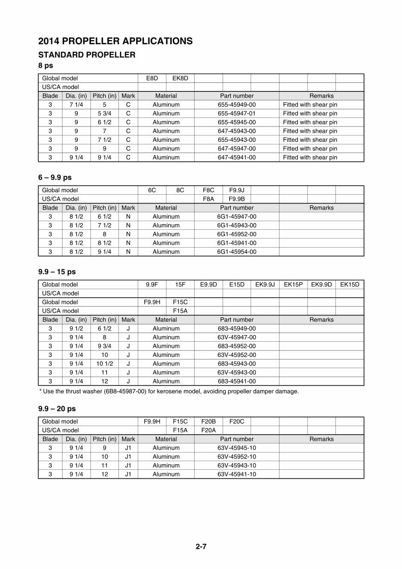
2-7
2014 PROPELLER APPLICATIONSSTANDARD PROPELLER8 ps
6 – 9.9 ps
9.9 – 15 ps
* Use the thrust washer (6B8-45987-00) for kerosene model, avoiding propeller damper damage.
9.9 – 20 ps
Global model E8D EK8DUS/CA model
Blade Dia. (in) Pitch (in) Mark Material Part number Remarks
3 7 1/4 5 C Aluminum 655-45949-00 Fitted with shear pin3 9 5 3/4 C Aluminum 655-45947-01 Fitted with shear pin
3 9 6 1/2 C Aluminum 655-45945-00 Fitted with shear pin
3 9 7 C Aluminum 647-45943-00 Fitted with shear pin3 9 7 1/2 C Aluminum 655-45943-00 Fitted with shear pin
3 9 9 C Aluminum 647-45947-00 Fitted with shear pin
3 9 1/4 9 1/4 C Aluminum 647-45941-00 Fitted with shear pin
Global model 6C 8C F8C F9.9J
US/CA model F8A F9.9BBlade Dia. (in) Pitch (in) Mark Material Part number Remarks
3 8 1/2 6 1/2 N Aluminum 6G1-45947-00
3 8 1/2 7 1/2 N Aluminum 6G1-45943-00
3 8 1/2 8 N Aluminum 6G1-45952-003 8 1/2 8 1/2 N Aluminum 6G1-45941-00
3 8 1/2 9 1/4 N Aluminum 6G1-45954-00
Global model 9.9F 15F E9.9D E15D EK9.9J EK15P EK9.9D EK15D
US/CA model
Global model F9.9H F15CUS/CA model F15ABlade Dia. (in) Pitch (in) Mark Material Part number Remarks
3 9 1/2 6 1/2 J Aluminum 683-45949-003 9 1/4 8 J Aluminum 63V-45947-00
3 9 1/4 9 3/4 J Aluminum 683-45952-00
3 9 1/4 10 J Aluminum 63V-45952-003 9 1/4 10 1/2 J Aluminum 683-45943-00
3 9 1/4 11 J Aluminum 63V-45943-00
3 9 1/4 12 J Aluminum 683-45941-00
Global model F9.9H F15C F20B F20C
US/CA model F15A F20ABlade Dia. (in) Pitch (in) Mark Material Part number Remarks
3 9 1/4 9 J1 Aluminum 63V-45945-10
3 9 1/4 10 J1 Aluminum 63V-45952-10
3 9 1/4 11 J1 Aluminum 63V-45943-103 9 1/4 12 J1 Aluminum 63V-45941-10
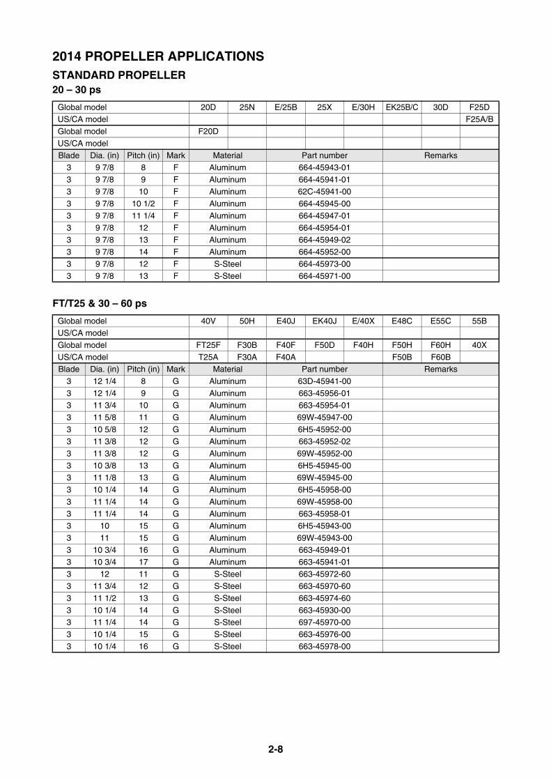
2-8
2014 PROPELLER APPLICATIONSSTANDARD PROPELLER20 – 30 ps
FT/T25 & 30 – 60 ps
Global model 20D 25N E/25B 25X E/30H EK25B/C 30D F25DUS/CA model F25A/B
Global model F20D
US/CA modelBlade Dia. (in) Pitch (in) Mark Material Part number Remarks
3 9 7/8 8 F Aluminum 664-45943-01
3 9 7/8 9 F Aluminum 664-45941-013 9 7/8 10 F Aluminum 62C-45941-00
3 9 7/8 10 1/2 F Aluminum 664-45945-00
3 9 7/8 11 1/4 F Aluminum 664-45947-01
3 9 7/8 12 F Aluminum 664-45954-013 9 7/8 13 F Aluminum 664-45949-02
3 9 7/8 14 F Aluminum 664-45952-00
3 9 7/8 12 F S-Steel 664-45973-003 9 7/8 13 F S-Steel 664-45971-00
Global model 40V 50H E40J EK40J E/40X E48C E55C 55BUS/CA model
Global model FT25F F30B F40F F50D F40H F50H F60H 40X
US/CA model T25A F30A F40A F50B F60BBlade Dia. (in) Pitch (in) Mark Material Part number Remarks
3 12 1/4 8 G Aluminum 63D-45941-00
3 12 1/4 9 G Aluminum 663-45956-013 11 3/4 10 G Aluminum 663-45954-01
3 11 5/8 11 G Aluminum 69W-45947-00
3 10 5/8 12 G Aluminum 6H5-45952-003 11 3/8 12 G Aluminum 663-45952-02
3 11 3/8 12 G Aluminum 69W-45952-00
3 10 3/8 13 G Aluminum 6H5-45945-003 11 1/8 13 G Aluminum 69W-45945-00
3 10 1/4 14 G Aluminum 6H5-45958-00
3 11 1/4 14 G Aluminum 69W-45958-003 11 1/4 14 G Aluminum 663-45958-01
3 10 15 G Aluminum 6H5-45943-00
3 11 15 G Aluminum 69W-45943-003 10 3/4 16 G Aluminum 663-45949-01
3 10 3/4 17 G Aluminum 663-45941-01
3 12 11 G S-Steel 663-45972-603 11 3/4 12 G S-Steel 663-45970-60
3 11 1/2 13 G S-Steel 663-45974-60
3 10 1/4 14 G S-Steel 663-45930-003 11 1/4 14 G S-Steel 697-45970-00
3 10 1/4 15 G S-Steel 663-45976-00
3 10 1/4 16 G S-Steel 663-45978-00
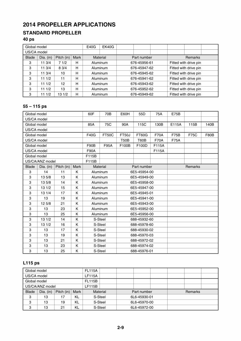
2-9
2014 PROPELLER APPLICATIONSSTANDARD PROPELLER40 ps
55 – 115 ps
L115 ps
Global model E40G EK40GUS/CA model
Blade Dia. (in) Pitch (in) Mark Material Part number Remarks
3 11 3/4 7 1/2 H Aluminum 676-45956-61 Fitted with drive pin3 11 3/4 8 3/4 H Aluminum 676-45947-62 Fitted with drive pin
3 11 3/4 10 H Aluminum 676-45945-62 Fitted with drive pin
3 11 1/2 11 H Aluminum 676-45941-62 Fitted with drive pin3 11 1/2 12 H Aluminum 676-45943-62 Fitted with drive pin
3 11 1/2 13 H Aluminum 676-45952-62 Fitted with drive pin
3 11 1/2 13 1/2 H Aluminum 676-45949-62 Fitted with drive pin
Global model 60F 70B E60H 55D 75A E75B
US/CA model
Global model 85A 75C 90A 115C 130B E115A 115B 140BUS/CA model
Global model F40G FT50C FT50J FT60G F70A F75B F75C F80B
US/CA model T50B T60B F70A F75AGlobal model F90B F95A F100B F100D F115A
US/CA model F90A F115A
Global model F115BUS/CA/ANZ model F115BBlade Dia. (in) Pitch (in) Mark Material Part number Remarks
3 14 11 K Aluminum 6E5-45954-003 13 5/8 13 K Aluminum 6E5-45949-00
3 13 5/8 14 K Aluminum 6E5-45958-00
3 13 1/2 15 K Aluminum 6E5-45947-003 13 1/4 17 K Aluminum 6E5-45945-01
3 13 19 K Aluminum 6E5-45941-00
3 12 5/8 21 K Aluminum 6E5-45943-003 13 23 K Aluminum 6E5-45952-00
3 13 25 K Aluminum 6E5-45956-00
3 13 1/2 14 K S-Steel 688-45932-603 13 1/2 16 K S-Steel 688-45978-60
3 13 17 K S-Steel 688-45930-02
3 13 19 K S-Steel 688-45970-033 13 21 K S-Steel 688-45972-02
3 13 23 K S-Steel 688-45974-02
3 13 25 K S-Steel 688-45976-01
Global model FL115A
US/CA model LF115AGlobal model FL115B
US/CA/ANZ model LF115BBlade Dia. (in) Pitch (in) Mark Material Part number Remarks
3 13 17 KL S-Steel 6L6-45930-01
3 13 19 KL S-Steel 6L6-45970-00
3 13 21 KL S-Steel 6L6-45972-00
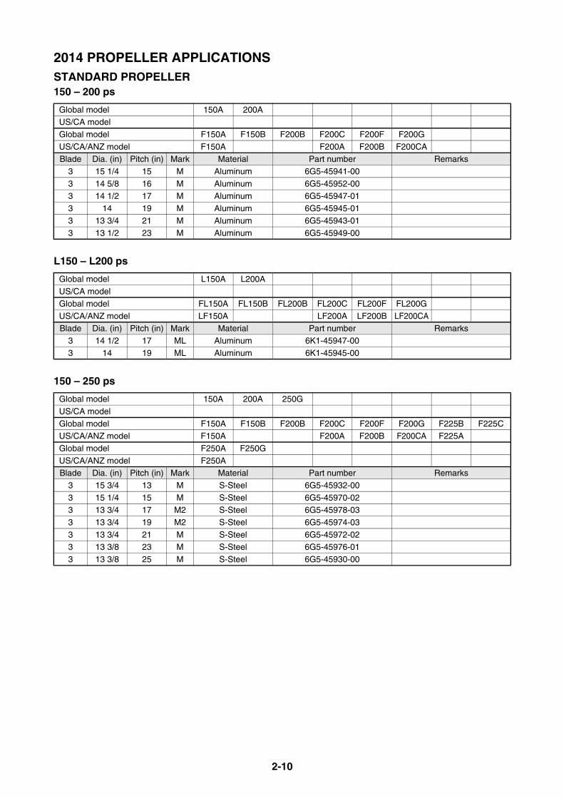
2-10
2014 PROPELLER APPLICATIONSSTANDARD PROPELLER150 – 200 ps
L150 – L200 ps
150 – 250 ps
Global model 150A 200AUS/CA model
Global model F150A F150B F200B F200C F200F F200G
US/CA/ANZ model F150A F200A F200B F200CABlade Dia. (in) Pitch (in) Mark Material Part number Remarks
3 15 1/4 15 M Aluminum 6G5-45941-00
3 14 5/8 16 M Aluminum 6G5-45952-003 14 1/2 17 M Aluminum 6G5-45947-01
3 14 19 M Aluminum 6G5-45945-01
3 13 3/4 21 M Aluminum 6G5-45943-01
3 13 1/2 23 M Aluminum 6G5-45949-00
Global model L150A L200A
US/CA modelGlobal model FL150A FL150B FL200B FL200C FL200F FL200G
US/CA/ANZ model LF150A LF200A LF200B LF200CA
Blade Dia. (in) Pitch (in) Mark Material Part number Remarks3 14 1/2 17 ML Aluminum 6K1-45947-00
3 14 19 ML Aluminum 6K1-45945-00
Global model 150A 200A 250G
US/CA model
Global model F150A F150B F200B F200C F200F F200G F225B F225CUS/CA/ANZ model F150A F200A F200B F200CA F225A
Global model F250A F250G
US/CA/ANZ model F250ABlade Dia. (in) Pitch (in) Mark Material Part number Remarks
3 15 3/4 13 M S-Steel 6G5-45932-00
3 15 1/4 15 M S-Steel 6G5-45970-023 13 3/4 17 M2 S-Steel 6G5-45978-03
3 13 3/4 19 M2 S-Steel 6G5-45974-03
3 13 3/4 21 M S-Steel 6G5-45972-023 13 3/8 23 M S-Steel 6G5-45976-01
3 13 3/8 25 M S-Steel 6G5-45930-00
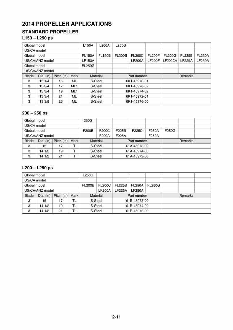
2-11
2014 PROPELLER APPLICATIONSSTANDARD PROPELLERL150 – L250 ps
200 – 250 ps
L200 – L250 ps
Global model L150A L200A L250GUS/CA model
Global model FL150A FL150B FL200B FL200C FL200F FL200G FL225B FL250A
US/CA/ANZ model LF150A LF200A LF200F LF200CA LF225A LF250AGlobal model FL250G
US/CA/ANZ model
Blade Dia. (in) Pitch (in) Mark Material Part number Remarks3 15 1/4 15 ML S-Steel 6K1-45970-01
3 13 3/4 17 ML1 S-Steel 6K1-45978-02
3 13 3/4 19 ML1 S-Steel 6K1-45974-02
3 13 3/4 21 ML S-Steel 6K1-45972-013 13 3/8 23 ML S-Steel 6K1-45976-00
Global model 250GUS/CA model
Global model F200B F200C F225B F225C F250A F250G
US/CA/ANZ model F200A F225A F250ABlade Dia. (in) Pitch (in) Mark Material Part number Remarks
3 15 17 T S-Steel 61A-45978-00
3 14 1/2 19 T S-Steel 61A-45974-003 14 1/2 21 T S-Steel 61A-45972-00
Global model L250GUS/CA model
Global model FL200B FL200C FL225B FL250A FL250G
US/CA/ANZ model LF200A LF225A LF250ABlade Dia. (in) Pitch (in) Mark Material Part number Remarks
3 15 17 TL S-Steel 61B-45978-00
3 14 1/2 19 TL S-Steel 61B-45974-003 14 1/2 21 TL S-Steel 61B-45972-00

2-12
2014 PROPELLER APPLICATIONSSTANDARD PROPELLERS (Shift Dampener System [SDS])55 – 115 ps
Global model 55D 60F E60H 70B 75A E75B 75C 85AUS/CA model
Global model 90A E115A 115B 115C 130B 140B F40G FT50C
US/CA modelGlobal model FT50J FT60G F70A F75B F75C F80B F90B F95A
US/CA model T50B T60B T70A F75A F90A
Global model F100B F100D F115AUS/CA model F115A
Global model F115B
US/CA/ANZ model F115B
Blade Dia. (in) Pitch (in) Mark Material Part number Remarks3 13 1/2 9 K Aluminum 6EK-45941-00
3 13 1/2 10 1/2 K Aluminum 6EK-45943-00
3 13 1/2 12 K Aluminum 6EK-45945-003 13 1/2 14 K Aluminum 6EK-45947-00
3 13 1/4 16 K Aluminum 6EK-45949-00

2-13
2014 PROPELLER APPLICATIONSDUAL THRUST PROPELLERS6 – 9.9 ps
8 – 9.9 ps
9.9 – 15 ps
* Use the thrust washer (6B8-45987-00) for kerosene model, avoiding propeller damper damage.
20 – 30 ps
25 ps
50 – 70 ps
Global model 6C 8C F8C F9.9JUS/CA model F8A F9.9B
Blade Dia. (in) Pitch (in) Mark Material Part number Remarks
3 9 5 N Aluminum 6G1-W4592-003 9 7 N Aluminum 6G1-W4591-01
Global model FT8D FT9.9L
US/CA model T9.9BBlade Dia. (in) Pitch (in) Mark Material Part number Remarks
3 11 3/4 5 3/4 R Aluminum 69G-45941-00
3 11 3/4 7 R Aluminum 69G-45943-003 11 3/4 9 1/4 R Aluminum 6G8-45947-00
Global model 9.9F 15F E9.9D E15D EK9.9J EK15P EK9.9D EK15DUS/CA model
Global model F9.9H F15C
US/CA model F15ABlade Dia. (in) Pitch (in) Mark Material Part number Remarks
3 9 3/4 6 1/2 J Aluminum 683-W4592-02
3 9 3/4 8 J Aluminum 683-W4591-02
Global model 30D F25D E25B 30H E30H
US/CA model F25A
Blade Dia. (in) Pitch (in) Mark Material Part number Remarks3 10 5/8 8 1/4 F Aluminum 6J8-W4591-00 For PT/PTT/Hydro model.
Global model FT25FUS/CA model T25A
Blade Dia. (in) Pitch (in) Mark Material Part number Remarks
3 12 1/4 9 G Aluminum 68U-45941-00
Global model FT50C FT50J FT60G F70A
US/CA model T50B T60B F70ABlade Dia. (in) Pitch (in) Mark Material Part number Remarks
3 14 11 K Aluminum 68S-45941-00
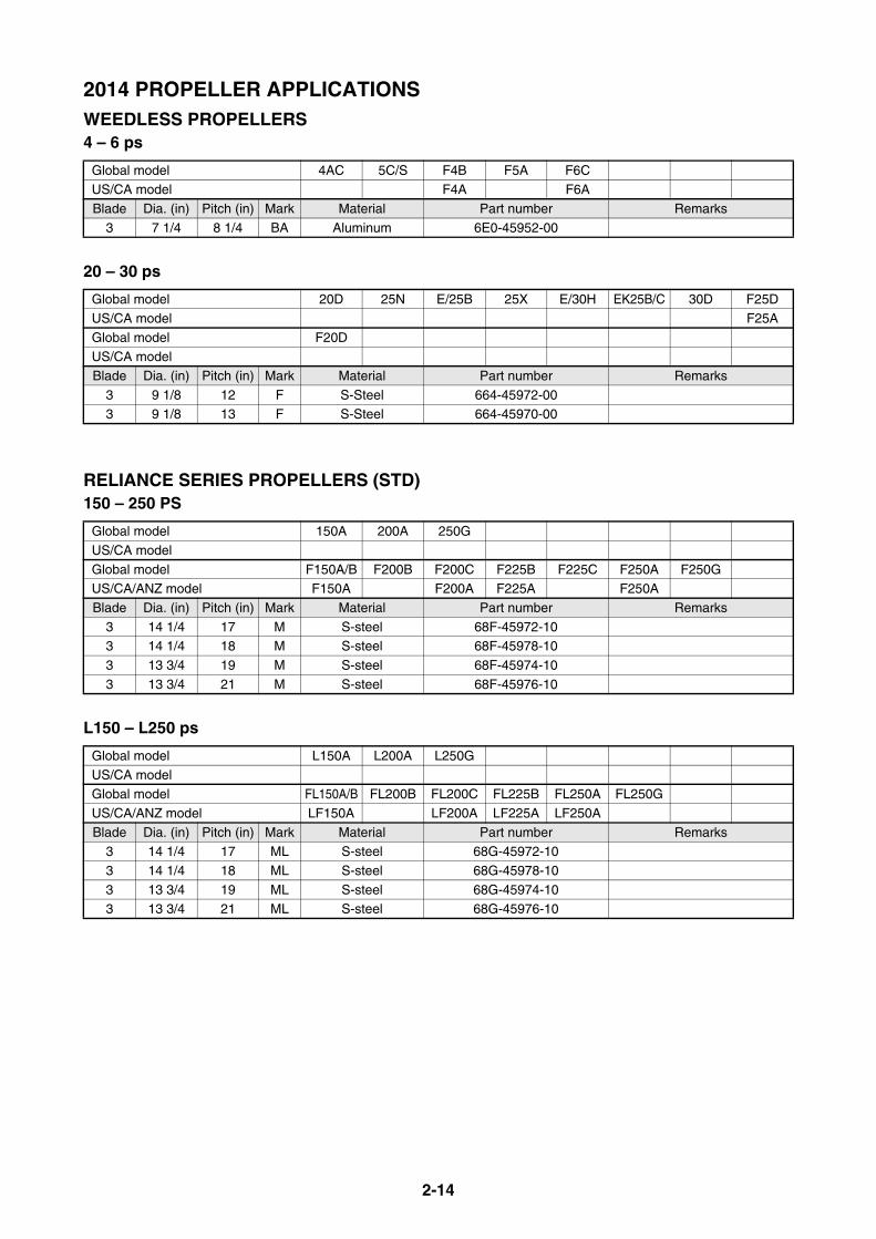
2-14
2014 PROPELLER APPLICATIONSWEEDLESS PROPELLERS4 – 6 ps
20 – 30 ps
RELIANCE SERIES PROPELLERS (STD)150 – 250 PS
L150 – L250 ps
Global model 4AC 5C/S F4B F5A F6CUS/CA model F4A F6A
Blade Dia. (in) Pitch (in) Mark Material Part number Remarks
3 7 1/4 8 1/4 BA Aluminum 6E0-45952-00
Global model 20D 25N E/25B 25X E/30H EK25B/C 30D F25D
US/CA model F25A
Global model F20DUS/CA model
Blade Dia. (in) Pitch (in) Mark Material Part number Remarks
3 9 1/8 12 F S-Steel 664-45972-003 9 1/8 13 F S-Steel 664-45970-00
Global model 150A 200A 250G
US/CA model
Global model F150A/B F200B F200C F225B F225C F250A F250GUS/CA/ANZ model F150A F200A F225A F250A
Blade Dia. (in) Pitch (in) Mark Material Part number Remarks
3 14 1/4 17 M S-steel 68F-45972-103 14 1/4 18 M S-steel 68F-45978-10
3 13 3/4 19 M S-steel 68F-45974-10
3 13 3/4 21 M S-steel 68F-45976-10
Global model L150A L200A L250G
US/CA modelGlobal model FL150A/B FL200B FL200C FL225B FL250A FL250G
US/CA/ANZ model LF150A LF200A LF225A LF250A
Blade Dia. (in) Pitch (in) Mark Material Part number Remarks3 14 1/4 17 ML S-steel 68G-45972-10
3 14 1/4 18 ML S-steel 68G-45978-10
3 13 3/4 19 ML S-steel 68G-45974-103 13 3/4 21 ML S-steel 68G-45976-10
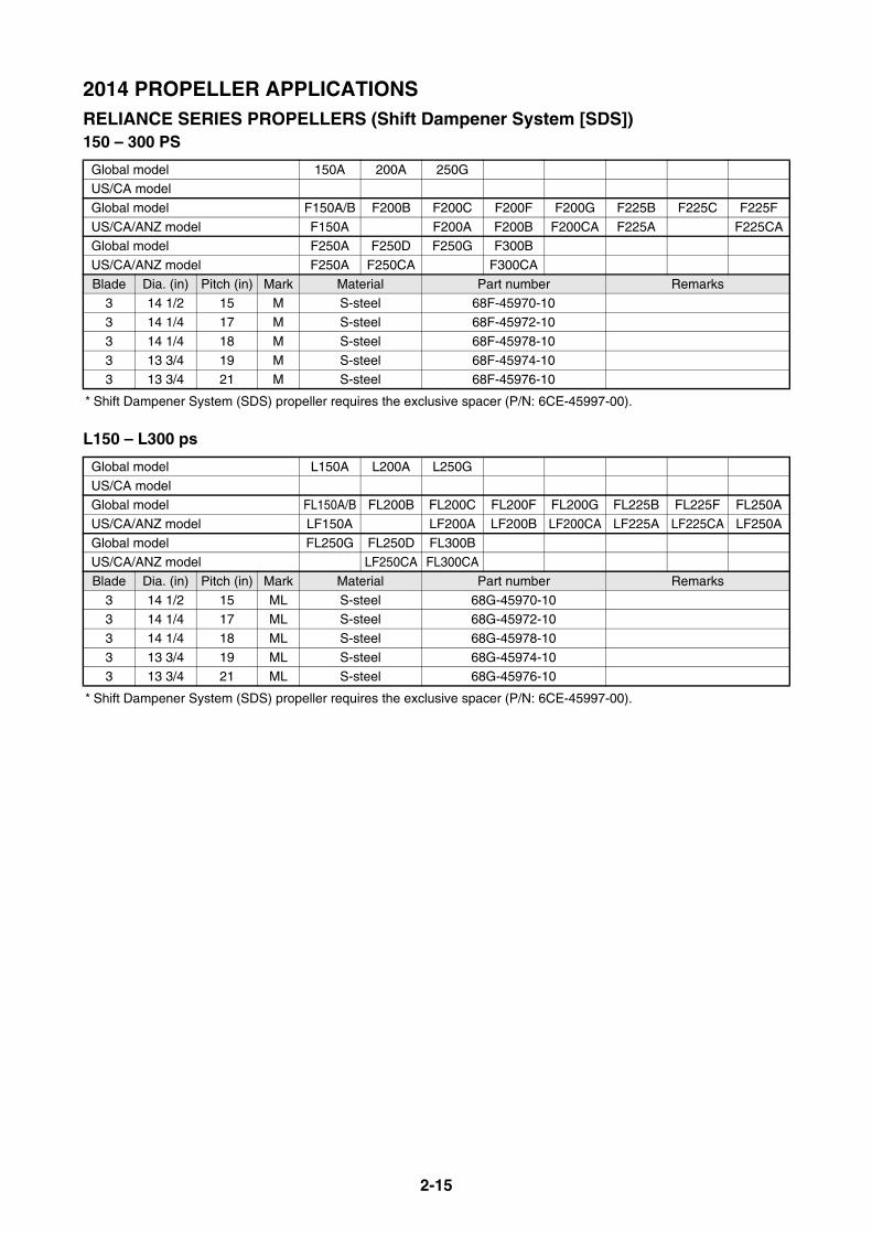
2-15
2014 PROPELLER APPLICATIONSRELIANCE SERIES PROPELLERS (Shift Dampener System [SDS])150 – 300 PS
* Shift Dampener System (SDS) propeller requires the exclusive spacer (P/N: 6CE-45997-00).
L150 – L300 ps
* Shift Dampener System (SDS) propeller requires the exclusive spacer (P/N: 6CE-45997-00).
Global model 150A 200A 250GUS/CA model
Global model F150A/B F200B F200C F200F F200G F225B F225C F225F
US/CA/ANZ model F150A F200A F200B F200CA F225A F225CAGlobal model F250A F250D F250G F300B
US/CA/ANZ model F250A F250CA F300CA
Blade Dia. (in) Pitch (in) Mark Material Part number Remarks3 14 1/2 15 M S-steel 68F-45970-10
3 14 1/4 17 M S-steel 68F-45972-10
3 14 1/4 18 M S-steel 68F-45978-10
3 13 3/4 19 M S-steel 68F-45974-103 13 3/4 21 M S-steel 68F-45976-10
Global model L150A L200A L250G
US/CA modelGlobal model FL150A/B FL200B FL200C FL200F FL200G FL225B FL225F FL250A
US/CA/ANZ model LF150A LF200A LF200B LF200CA LF225A LF225CA LF250A
Global model FL250G FL250D FL300BUS/CA/ANZ model LF250CA FL300CA
Blade Dia. (in) Pitch (in) Mark Material Part number Remarks
3 14 1/2 15 ML S-steel 68G-45970-103 14 1/4 17 ML S-steel 68G-45972-10
3 14 1/4 18 ML S-steel 68G-45978-10
3 13 3/4 19 ML S-steel 68G-45974-103 13 3/4 21 ML S-steel 68G-45976-10
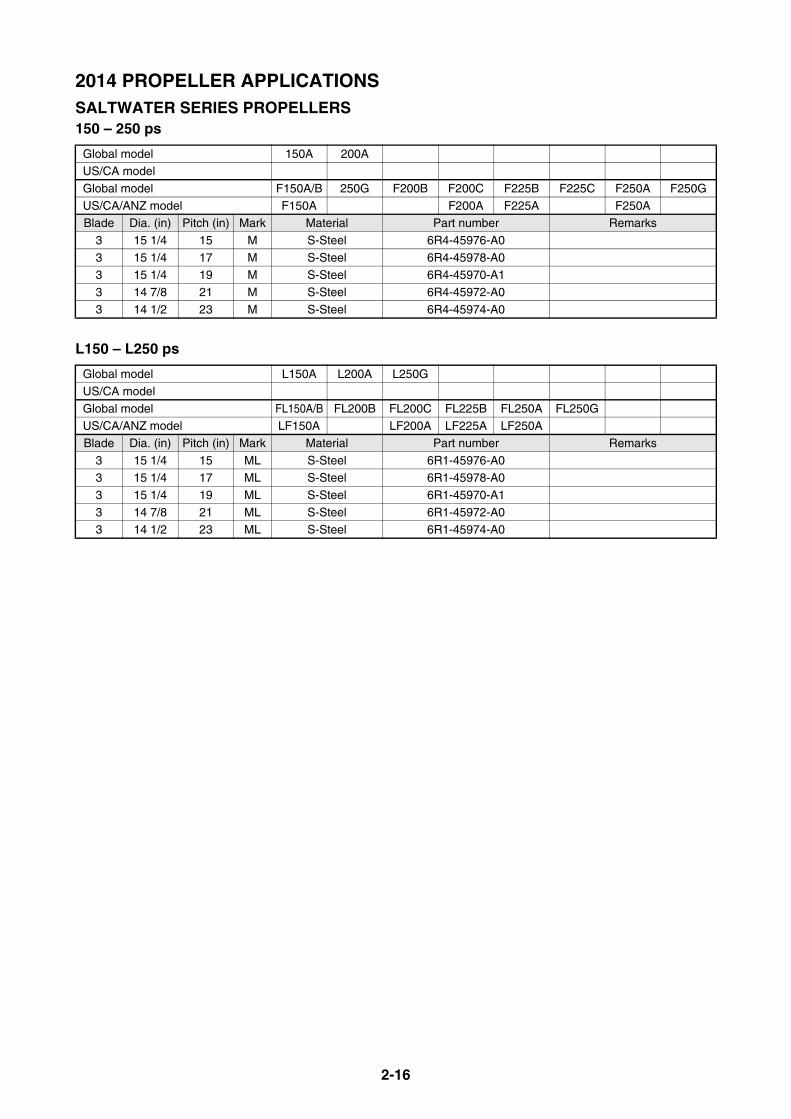
2-16
2014 PROPELLER APPLICATIONSSALTWATER SERIES PROPELLERS150 – 250 ps
L150 – L250 ps
Global model 150A 200AUS/CA model
Global model F150A/B 250G F200B F200C F225B F225C F250A F250G
US/CA/ANZ model F150A F200A F225A F250ABlade Dia. (in) Pitch (in) Mark Material Part number Remarks
3 15 1/4 15 M S-Steel 6R4-45976-A0
3 15 1/4 17 M S-Steel 6R4-45978-A03 15 1/4 19 M S-Steel 6R4-45970-A1
3 14 7/8 21 M S-Steel 6R4-45972-A0
3 14 1/2 23 M S-Steel 6R4-45974-A0
Global model L150A L200A L250G
US/CA model
Global model FL150A/B FL200B FL200C FL225B FL250A FL250GUS/CA/ANZ model LF150A LF200A LF225A LF250A
Blade Dia. (in) Pitch (in) Mark Material Part number Remarks
3 15 1/4 15 ML S-Steel 6R1-45976-A03 15 1/4 17 ML S-Steel 6R1-45978-A0
3 15 1/4 19 ML S-Steel 6R1-45970-A1
3 14 7/8 21 ML S-Steel 6R1-45972-A03 14 1/2 23 ML S-Steel 6R1-45974-A0

2-17
2014 PROPELLER APPLICATIONSSALTWATER SERIES II PROPELLERS (STD)150 – 300 ps
(*1) The blade contacts 6J9 lower-case.
L150 – L300 ps
(*1) The blade contacts 6J9 lower-case.
Global model 200A 250GUS/CA model
Global model F150A/B F200B F200C F225B F225C F250A F250B F250G
US/CA/ANZ model F150A F200A F225A F250ABlade Dia. (in) Pitch (in) Mark Material Part number Remarks
3 15 3/4 15 T S-Steel 6D0-45976-00 For V6 3.1/3.3L model. (*1)
3 15 1/2 17 T S-Steel 6D0-45978-003 15 1/4 19 T S-Steel 6D0-45970-00
3 15 21 T S-Steel 6D0-45972-00
3 14 3/4 23 T S-Steel 6D0-45974-00
Global model L150A L200A L250GUS/CA model
Global model FL150A/B FL200B FL200C FL200F FL225B FL250A FL250G
US/CA/ANZ model LF150A LF200A LF200B LF225A LF250ABlade Dia. (in) Pitch (in) Mark Material Part number Remarks
3 15 3/4 15 TL S-Steel 6D1-45976-00 For V6 3.1/3.3L model. (*1)
3 15 1/2 17 TL S-Steel 6D1-45978-003 15 1/4 19 TL S-Steel 6D1-45970-10
3 15 21 TL S-Steel 6D1-45972-10
3 14 3/4 23 TL S-Steel 6D1-45974-00

2-18
2014 PROPELLER APPLICATIONSSALTWATER SERIES II PROPELLERS (Shift Dampener System [SDS])150 – 300 ps
* Shift Dampener System (SDS) propeller requires the exclusive spacer (P/N: 6CE-45997-00).(*1) The blade contacts 6J9 lower-case.
L150 – L300 ps
* Shift Dampener System (SDS) propeller requires the exclusive spacer (P/N: 6CE-45997-00).(*1) The blade contacts 6J9 lower-case.
Global model 150A 200A 250GUS/CA model
Global model F150A/B F175A F200B F200C F200F F200G F225B F225C
US/CA/ANZ model F150A F175A F200A F200B F200CA F225AGlobal model F225F F250A F250G F250D F300B
US/CA/ANZ model F225CA F250A F250CA F300CA
Blade Dia. (in) Pitch (in) Mark Material Part number Remarks
3 15 3/4 13 T S-Steel 6CE-45930-00For V6 3.1/3.3/4.2L, L4 2.8L model. (*1)
3 15 3/4 15 T S-Steel 6CE-45976-00For V6 3.1/3.3/4.2L, L4 2.8L model. (*1)
3 15 1/2 16 T S-Steel 6CE-45938-003 15 1/2 17 T S-Steel 6CE-45978-00
3 15 1/4 18 T S-Steel 6CE-45934-00
3 15 1/4 19 T S-Steel 6CE-45970-103 15 20 T S-Steel 6CE-45932-00
3 15 21 T S-Steel 6CE-45972-10
3 14 3/4 22 T S-Steel 6CE-45936-003 14 3/4 23 T S-Steel 6CE-45974-00
Global model L150A L200A L250G
US/CA model
Global model FL150A/B FL200B FL200C FL200F FL200G FL225B FL225F FL250AUS/CA/ANZ model LF150A LF200A LF200B LF200CA LF225A F225CA LF250A
Global model FL250G FL250D FL300B
US/CA/ANZ model LF250CA LF300CABlade Dia. (in) Pitch (in) Mark Material Part number Remarks
3 15 3/4 13 TL S-Steel 6CF-45930-00For V6 3.1/3.3/4.2L model. (*1)
3 15 3/4 15 TL S-Steel 6CF-45976-00For V6 3.1/3.3/4.2L model. (*1)
3 15 1/2 17 TL S-Steel 6CF-45978-00
3 15 1/4 18 TL S-Steel 6CF-45934-003 15 1/4 19 TL S-Steel 6CF-45970-10
3 15 20 TL S-Steel 6CF-45932-00
3 15 21 TL S-Steel 6CF-45972-103 35 3/4 22 TL S-Steel 6CF-45936-00
3 14 3/4 23 TL S-Steel 6CF-45974-00

2-19
2014 PROPELLER APPLICATIONSSALTWATER SERIES HS4 PROPELLERS (STD)150 – 300 ps
L150 – L300 ps
SALTWATER SERIES HS4 PROPELLERS (Shift Dampener System [SDS])150 – 300 ps
* Shift Dampener System (SDS) propeller requires the exclusive spacer (P/N: 6CE-45997-00).
L150 – L300 ps
* Shift Dampener System (SDS) propeller requires the exclusive spacer (P/N: 6CE-45997-00).
Global model 150A 200A 250GUS/CA model
Global model F150A/B F200B F200C F225A F225B F225C F250A F250B
US/CA/ANZ model F150A F200A F225A F250AGlobal model F250G
US/CA/ANZ model
Blade Dia. (in) Pitch (in) Mark Material Part number Remarks4 15 21 T S-Steel 6BR-45B70-00
4 15 22 T S-Steel 6BR-45B72-00
4 15 23 T S-Steel 6BR-45B74-00
Global model L150A L200A L250G
US/CA model
Global model FL150A/B FL200B FL200C FL200F FL225B FL250A FL250GUS/CA/ANZ model LF150A LF200A LF200B LF225A LF250A
Blade Dia. (in) Pitch (in) Mark Material Part number Remarks
4 15 21 TL S-Steel 6BS-45B70-004 15 22 TL S-Steel 6BS-45B72-00
4 15 23 TL S-Steel 6BS-45B74-00
Global model 150A 200A 250G
US/CA modelGlobal model F150A/B F200B F200C F200F F200G F225B F225C F225F
US/CA/ANZ model F150A F200A F200B F200CA F225A F225CA
Global model F250A F250G F250G F250D F300BUS/CA/ANZ model F250A F250CA F300CA
Blade Dia. (in) Pitch (in) Mark Material Part number Remarks
4 15 21 T S-Steel 6CE-45B70-004 15 22 T S-Steel 6CE-45B72-00
4 15 23 T S-Steel 6CE-45B74-00
Global model L150A L200A L250GUS/CA model
Global model FL150A/B FL200B FL200C FL200F FL200G FL225B FL225F FL250A
US/CA/ANZ model LF150A LF200A LF200B LF200CA LF225A LF225CA LF250AGlobal model FL250G FL250D FL300B
US/CA/ANZ model LF250CA LF300CA
Blade Dia. (in) Pitch (in) Mark Material Part number Remarks4 15 21 TL S-Steel 6CF-45B70-00
4 15 22 TL S-Steel 6CF-45B72-00
4 15 23 TL S-Steel 6CF-45B74-00

2-20
2014 PROPELLER APPLICATIONSSALTWATER SERIES XL PROPELLERS (Shift Dampener System [SDS])350 ps (V8 engine)
* Shift Dampener System (SDS) propeller requires the exclusive spacer (P/N: 6AW-45997-10).
L350 ps (V8 engine)
* Shift Dampener System (SDS) propeller requires the exclusive spacer (P/N: 6AW-45997-10).
SALTWATER SERIES XL4 PROPELLERS (Shift Dampener System [SDS])350 ps (V8 engine)
* Shift Dampener System (SDS) propeller requires the exclusive spacer (P/N: 6AW-45997-10).
L350 ps (V8 engine)
* Shift Dampener System (SDS) propeller requires the exclusive spacer (P/N: 6AW-45997-10).
Global model F350AUS/CA/ANZ model F350CB
Blade Dia. (in) Pitch (in) Mark Material Part number Remarks
3 16 1/4 15 X S-Steel 6AW-45970-103 16 1/4 17 X S-Steel 6AW-45972-10
3 15 1/2 19 X S-Steel 6AW-45974-10
3 15 1/4 21 X S-Steel 6AW-45976-103 15 1/4 23 X S-Steel 6AW-45978-10
Global model FL350A
US/CA/ANZ model LF350CB
Blade Dia. (in) Pitch (in) Mark Material Part number Remarks3 16 1/4 15 XL S-Steel 6AX-45970-10
3 16 1/4 17 XL S-Steel 6AX-45972-10
3 15 1/2 19 XL S-Steel 6AX-45974-103 15 1/4 21 XL S-Steel 6AX-45976-10
3 15 1/4 23 XL S-Steel 6AX-45978-10
Global model FL350A
US/CA/ANZ model LF350CB
Blade Dia. (in) Pitch (in) Mark Material Part number Remarks4 16 1/8 15 X S-Steel 6AW-45B70-10
4 16 1/8 17 X S-Steel 6AW-45B72-10
4 15 3/8 22 X S-Steel 6AW-45B76-104 15 3/8 24 X S-Steel 6AW-45B74-10
Global model FL350A
US/CA/ANZ model LF350CBBlade Dia. (in) Pitch (in) Mark Material Part number Remarks
4 16 1/8 15 XL S-Steel 6AX-45B70-10
4 16 1/8 17 XL S-Steel 6AX-45B72-104 15 3/8 22 XL S-Steel 6AX-45B76-10
4 15 3/8 24 XL S-Steel 6AX-45B74-10

2-21
2014 PROPELLER APPLICATIONSVMAX SERIES PROPELLERS200 – 275 ps (SHO engine)
PERFORMANCE SERIES PROPELLERS50 – 140 ps
150 – 200 ps
Global model F150C F165A F200D F225D F250C F225G F250F F275AUS/CA/ANZ model VF150A VF200A VF225A VF250A
Blade Dia. (in) Pitch (in) Mark Material Part number Remarks
3 15 1/8 22 T1 S-Steel 6CB-45932-10 Ventless3 15 1/8 23 T1 S-Steel 6CB-45974-10 Ventless
3 15 1/8 24 T1 S-Steel 6CB-45930-10 Ventless
3 15 1/8 25 T1 S-Steel 6CB-45972-10 Ventless3 15 1/8 26 T1 S-Steel 6CB-45978-10 Ventless
3 15 1/8 27 T1 S-Steel 6CB-45970-10 Ventless
3 14 3/4 29 T1 S-Steel 6CB-45976-00 Ventless
Global model 55D 60F E60H 70B 75/85A E75B 90A 115B/C
US/CA modelGlobal model E115A 130/140B F40G FT50C FT50J FT60G F70A F75B/C
US/CA model T50B T60B F70A F75A
Global model F80B F90B F95A F100B F100D F115AUS/CA model F90A F115A
Global model F115B
US/CA/ANZ model F115BBlade Dia. (in) Pitch (in) Mark Material Part number Remarks
3 13 1/2 17 K S-Steel 62A-45976-00
3 13 1/2 19 K S-Steel 62A-45974-103 13 1/2 21 K S-Steel 62A-45970-10
3 13 1/2 23 K S-Steel 62A-45972-10
Global model Z150Q
US/CA model VZ150Blade Dia. (in) Pitch (in) Mark Material Part number Remarks
3 14 1/2 21 M S-Steel 66K-45976-B0
3 14 1/2 23 M S-Steel 66K-45974-B0
3 14 1/2 25 M S-Steel 66K-45972-B03 14 1/2 27 M S-Steel 66K-45970-B0

2-22
2014 PROPELLER APPLICATIONSHIGH PERFORMANCE SERIES PROPELLERS60 – 200 ps
* For L-transom engine matching sports boat.
Global model 60F 70B 75/85A 75C 90A 115B/C 130/140B Z150QUS/CA model VZ150
Global model 150A 200A
US/CA modelBlade Dia. (in) Pitch (in) Mark Material Part number Remarks
3 14 20 P S-Steel 6E5-45970-10 Special purpose
3 14 22 P S-Steel 6E5-45976-10 Special purpose3 14 24 P S-Steel 6E5-45972-10 Special purpose
3 14 26 P S-Steel 6E5-45978-10 Special purpose
3 14 28 P S-Steel 6E5-45974-10 Special purpose
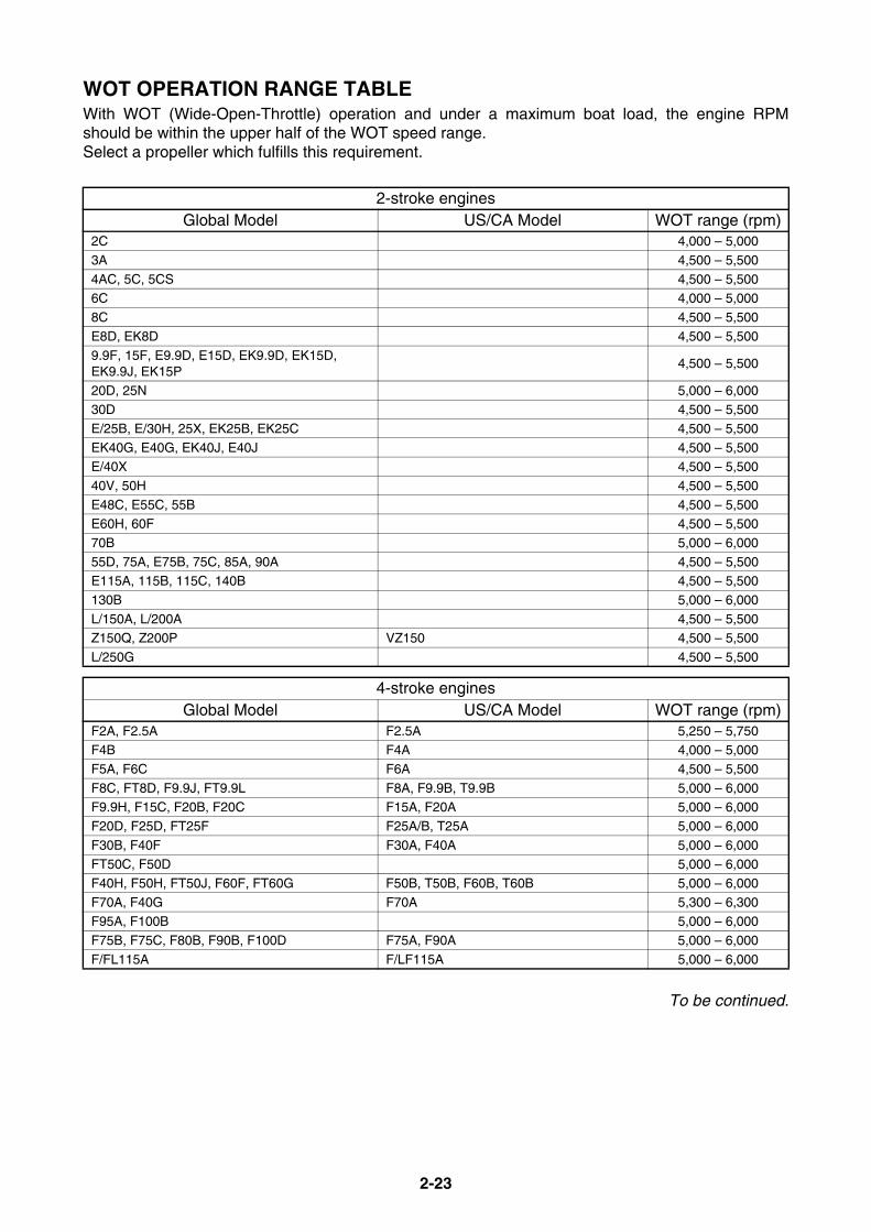
2-23
WOT OPERATION RANGE TABLEWith WOT (Wide-Open-Throttle) operation and under a maximum boat load, the engine RPMshould be within the upper half of the WOT speed range.Select a propeller which fulfills this requirement.
To be continued.
2-stroke enginesGlobal Model US/CA Model WOT range (rpm)
2C 4,000 – 5,000
3A 4,500 – 5,500
4AC, 5C, 5CS 4,500 – 5,5006C 4,000 – 5,000
8C 4,500 – 5,500
E8D, EK8D 4,500 – 5,500
9.9F, 15F, E9.9D, E15D, EK9.9D, EK15D, EK9.9J, EK15P
4,500 – 5,500
20D, 25N 5,000 – 6,00030D 4,500 – 5,500
E/25B, E/30H, 25X, EK25B, EK25C 4,500 – 5,500
EK40G, E40G, EK40J, E40J 4,500 – 5,500E/40X 4,500 – 5,500
40V, 50H 4,500 – 5,500
E48C, E55C, 55B 4,500 – 5,500E60H, 60F 4,500 – 5,500
70B 5,000 – 6,000
55D, 75A, E75B, 75C, 85A, 90A 4,500 – 5,500E115A, 115B, 115C, 140B 4,500 – 5,500
130B 5,000 – 6,000
L/150A, L/200A 4,500 – 5,500Z150Q, Z200P VZ150 4,500 – 5,500
L/250G 4,500 – 5,500
4-stroke enginesGlobal Model US/CA Model WOT range (rpm)
F2A, F2.5A F2.5A 5,250 – 5,750F4B F4A 4,000 – 5,000
F5A, F6C F6A 4,500 – 5,500
F8C, FT8D, F9.9J, FT9.9L F8A, F9.9B, T9.9B 5,000 – 6,000F9.9H, F15C, F20B, F20C F15A, F20A 5,000 – 6,000
F20D, F25D, FT25F F25A/B, T25A 5,000 – 6,000
F30B, F40F F30A, F40A 5,000 – 6,000FT50C, F50D 5,000 – 6,000
F40H, F50H, FT50J, F60F, FT60G F50B, T50B, F60B, T60B 5,000 – 6,000
F70A, F40G F70A 5,300 – 6,300F95A, F100B 5,000 – 6,000
F75B, F75C, F80B, F90B, F100D F75A, F90A 5,000 – 6,000
F/FL115A F/LF115A 5,000 – 6,000

2-24
WOT OPERATION RANGE TABLE
If the engine RPM exceeds the recommended WOT range, replace with a larger pitch propeller.If the engine RPM does not reach the recommended WOT range, replace with a smaller pitch pro-peller.
NOTICEDo not run the engine at a speed which exceeds WOT range, as the engine could be dam-aged from overload or over rev.
* The engine rpm at WOT operation will be usually changed about 150 rpm if the pitch of propeller has beenchanged one inch.However, the change of rpm varies due to the propeller type, water type (salt or freshwater), boat type(weight or hull shape), etc.
* The maximum engine RPM will increase when the outboard motor is trimmed out.
4-stroke enginesGlobal Model US/CA/ANZ Model WOT range (rpm)
F/FL115B F/LF115B 5,300 – 6,300F/FL150A F/LF150A 5,000 – 6,000
F/FL150B 4,500 – 5,500
F150C, F165A VF150A 5,000 – 6,000F175A, F/FL200B, F/FL200C, F/FL200F, F/FL200G, F/FL225B, F225C, F/FL250A, F/FL250G
F175A, F/LF200A, F/LF200B, F/LF200CA, F/LF225A, F/LF250A
5,000 – 6,000
F200D, F225D, F250C, F225G, F250F, F275A VF200LA, VF225LA, VF250LA 5,000 – 6,000F/FL225F, F/FL250D, F/FL300B F/LF225CA, F/LF250CA, F/LF300CA 5,000 – 6,000
F/FL350A F/LF350CB 5,000 – 6,000
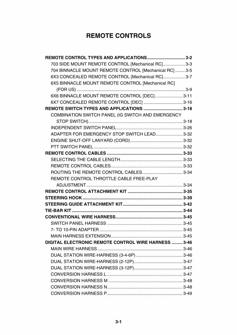
3-1
REMOTE CONTROLS
REMOTE CONTROL TYPES AND APPLICATIONS............................... 3-2703 SIDE MOUNT REMOTE CONTROL [Mechanical RC].................. 3-3
704 BINNACLE MOUNT REMOTE CONTROL [Mechanical RC] ........ 3-5
6X3 CONCEALED REMOTE CONTROL [Mechanical RC].................. 3-7
6X5 BINNACLE MOUNT REMOTE CONTROL [Mechanical RC]
(FOR US) ......................................................................................... 3-9
6X6 BINNACLE MOUNT REMOTE CONTROL [DEC]....................... 3-11
6X7 CONCEALED REMOTE CONTROL [DEC] ................................ 3-16
REMOTE SWITCH TYPES AND APPLICATIONS ................................ 3-18COMBINATION SWITCH PANEL (IG SWITCH AND EMERGENCY
STOP SWITCH)............................................................................. 3-18
INDEPENDENT SWITCH PANEL...................................................... 3-26
ADAPTER FOR EMERGENCY STOP SWITCH LEAD...................... 3-32
ENGINE SHUT-OFF LANYARD (CORD)........................................... 3-32
PTT SWITCH PANEL......................................................................... 3-32
REMOTE CONTROL CABLES .............................................................. 3-33SELECTING THE CABLE LENGTH................................................... 3-33
REMOTE CONTROL CABLES........................................................... 3-33
ROUTING THE REMOTE CONTROL CABLES................................. 3-34
REMOTE CONTROL THROTTLE CABLE FREE-PLAY
ADJUSTMENT............................................................................... 3-34
REMOTE CONTROL ATTACHMENT KIT ............................................. 3-35STEERING HOOK .................................................................................. 3-39STEERING GUIDE ATTACHMENT KIT................................................. 3-42TIE-BAR KIT ........................................................................................... 3-44CONVENTIONAL WIRE HARNESS....................................................... 3-45
SWITCH PANEL HARNESS .............................................................. 3-45
7- TO 10-PIN ADAPTER .................................................................... 3-45
MAIN HARNESS EXTENSION........................................................... 3-45
DIGITAL ELECTRONIC REMOTE CONTROL WIRE HARNESS ......... 3-46MAIN WIRE HARNESS...................................................................... 3-46
DUAL STATION WIRE-HARNESS (3-4-6P) ...................................... 3-46
DUAL STATION WIRE-HARNESS (2-12P)........................................ 3-47
DUAL STATION WIRE-HARNESS (3-12P)........................................ 3-47
CONVERSION HARNESS L .............................................................. 3-47
CONVERSION HARNESS M ............................................................. 3-48
CONVERSION HARNESS N.............................................................. 3-48
CONVERSION HARNESS P.............................................................. 3-49

3-2
REMOTE CONTROL TYPES AND APPLICATIONSA Yamaha outboard motor has one of two throttle control systems, either “Push To Open” or “PullTo Open”.For example, “Push To Open” means the throttle valve opens when the remote control inner cable isextended and then the throttle arm is pushed.Most models have “Push To Open” system.However, some following models have “Pull To Open” system.
The 10-pin connector is usually used for PTT and/or PT (Power Tilt) models.The 7-pin connector is for manual tilt models. But, F9.9J (F9.9B), FT9.9L (T9.9B), F15C (F15A) andF20B (F20A) have the 10-pin connector.Install the remote control box so that there is sufficient clearance between steering wheel andremote control lever operation area.
“Pull to Open” models
20D25B
E25B25N 30D
30HE30H
E40J EK40J E40G 55B E60H
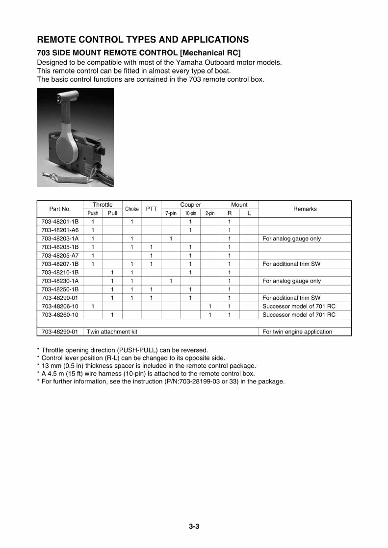
3-3
REMOTE CONTROL TYPES AND APPLICATIONS703 SIDE MOUNT REMOTE CONTROL [Mechanical RC]Designed to be compatible with most of the Yamaha Outboard motor models.This remote control can be fitted in almost every type of boat. The basic control functions are contained in the 703 remote control box.
* Throttle opening direction (PUSH-PULL) can be reversed.* Control lever position (R-L) can be changed to its opposite side.* 13 mm (0.5 in) thickness spacer is included in the remote control package.* A 4.5 m (15 ft) wire harness (10-pin) is attached to the remote control box.* For further information, see the instruction (P/N:703-28199-03 or 33) in the package.
Part No.Throttle
Choke PTTCoupler Mount
RemarksPush Pull 7-pin 10-pin 2-pin R L
703-48201-1B 1 1 1 1703-48201-A6 1 1 1
703-48203-1A 1 1 1 1 For analog gauge only
703-48205-1B 1 1 1 1 1
703-48205-A7 1 1 1 1703-48207-1B 1 1 1 1 1 For additional trim SW
703-48210-1B 1 1 1 1
703-48230-1A 1 1 1 1 For analog gauge only703-48250-1B 1 1 1 1 1
703-48290-01 1 1 1 1 1 For additional trim SW
703-48206-10 1 1 1 Successor model of 701 RC703-48260-10 1 1 1 Successor model of 701 RC
703-48290-01 Twin attachment kit For twin engine application

3-4
REMOTE CONTROL TYPES AND APPLICATIONS703 SIDE MOUNT REMOTE CONTROL DIMENSIONS
70 (
22.7
6)86
(3.
39)
226
(8.9
)
128 (5.04)
116.5 (4.59) 46 (1.81)
16 (
0.63
)
135 (5.31)
40 (1.57)
64.5 (2.54)
85.5 (3.37)
85 (3.35)30
(1.1
8)
56
(2.2
)
mm (in.)

3-5
REMOTE CONTROL TYPES AND APPLICATIONS704 BINNACLE MOUNT REMOTE CONTROL [Mechanical RC]Designed for use with electric start models. Best fitted to a boat with center console.Two types of levers, Single lever or Twin lever, are available to match the purpose of use andengine applications.Two types of control boxes, Premium or Standard type, are also available to match the boat design,cost, etc.
1 2
* Switch panel and extension wire-harness are required to connect to the engine 10-pin harness.* Throttle opening direction can be reversed.* Lever location can be changed to its opposite position.* For further information, see the instruction (P/N:704-28199-P0) in the package.
Ref. No.
Part No.Throttle
PTTLever
RemarksPush Pull R L Twin
1704-48203-P1 1 1 Premium704-48205-P1 1 1 1 Premium
704-48206-P1 1 1 1 Premium
2 704-48207-P1 1 1 1 Premium
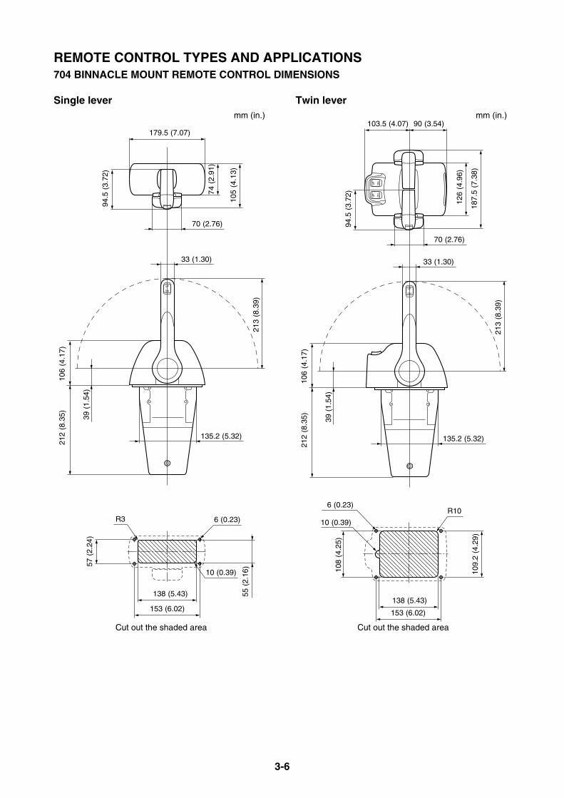
3-6
REMOTE CONTROL TYPES AND APPLICATIONS704 BINNACLE MOUNT REMOTE CONTROL DIMENSIONS
Single lever Twin lever
212
(8.3
5)10
6 (4
.17)
33 (1.30)
70 (2.76)
94.5
(3.
72)
74 (
2.91
)
105
(4.1
3)
179.5 (7.07)
55 (
2.16
)
153 (6.02)
138 (5.43)
6 (0.23)
10 (0.39)
57 (
2.24
)
135.2 (5.32)
39 (
1.54
)
213
(8.3
9)
R3
mm (in.)
Cut out the shaded area
212
(8.3
5)10
6 (4
.17)
33 (1.30)
70 (2.76)
94.5
(3.
72)
126
(4.9
6)
187.
5 (7
.38)
103.5 (4.07) 90 (3.54)
109.
2 (4
.29)
108
(4.2
5)
153 (6.02)
138 (5.43)
135.2 (5.32)
39 (
1.54
)
213
(8.3
9)6 (0.23)
10 (0.39)
R10
mm (in.)
Cut out the shaded area

3-7
REMOTE CONTROL TYPES AND APPLICATIONSREMOTE CONTROL SPACERDesigned to raise the control box 22 mm (0.9 in.) to make more clearance between the lever andthe dash board when the lever is in the WOT position.
6X3 CONCEALED REMOTE CONTROL [Mechanical RC]Designed for the electric start models. Best fitted to runabout type boats. The emergency shut-offswitch is incorporated into the control box.The mounting position can be selected from horizontal or inclined 30-degree up or down positiondepending on the boat design.
* The ignition switch panel without engine shut-off cord and 10-pin main harness are required to connect tothe engine.
* Throttle opening direction can be reversed.* For further information, see the instruction in the package.
Ref. No. Part No. Descriptions1 704-48293-20 Single
2 704-48293-30 Twin
Part No.Throttle
PTTMount
RemarksPush Pull R L
6X3-48206-01 1 1 1With emergency shut-off cord (2-pin coupler)
(1)(2)
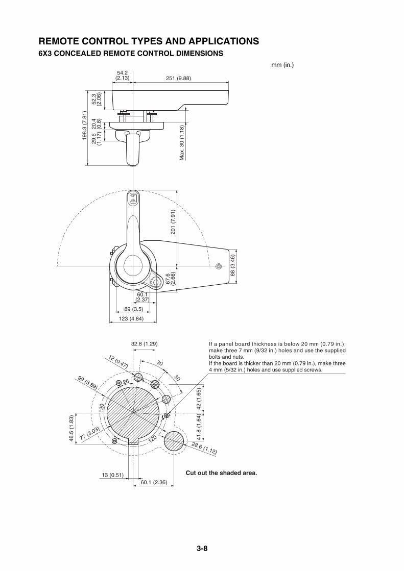
3-8
REMOTE CONTROL TYPES AND APPLICATIONS6X3 CONCEALED REMOTE CONTROL DIMENSIONS
If a panel board thickness is below 20 mm (0.79 in.), make three 7 mm (9/32 in.) holes and use the supplied bolts and nuts.If the board is thicker than 20 mm (0.79 in.), make three 4 mm (5/32 in.) holes and use supplied screws.
88 (
3.46
)
29.6
(1.1
7)20
.4(0
.8)
Max
. 30
(1.
18)
52.3
(2.0
6)
198.
3 (7
.81)
54.2(2.13) 251 (9.88)
201
(7.9
1)67
.6(2
.66)
123 (4.84)
89 (3.5)
60.1(2.37)
13 (0.51)
28.6 (1.12)
99 (3.89)
12 (0.47)
77 (3.03)
60.1 (2.36)
46.5
(1.
83)
32.8 (1.29)
30
26
120
120
30
41.8
(1.
64)
42 (
1.65
)
Cut out the shaded area.
mm (in.)
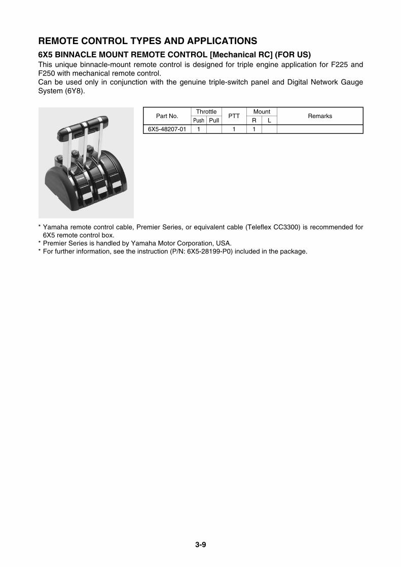
3-9
REMOTE CONTROL TYPES AND APPLICATIONS6X5 BINNACLE MOUNT REMOTE CONTROL [Mechanical RC] (FOR US)This unique binnacle-mount remote control is designed for triple engine application for F225 andF250 with mechanical remote control.Can be used only in conjunction with the genuine triple-switch panel and Digital Network GaugeSystem (6Y8).
* Yamaha remote control cable, Premier Series, or equivalent cable (Teleflex CC3300) is recommended for6X5 remote control box.
* Premier Series is handled by Yamaha Motor Corporation, USA.* For further information, see the instruction (P/N: 6X5-28199-P0) included in the package.
Part No.Throttle
PTTMount
RemarksPush Pull R L
6X5-48207-01 1 1 1
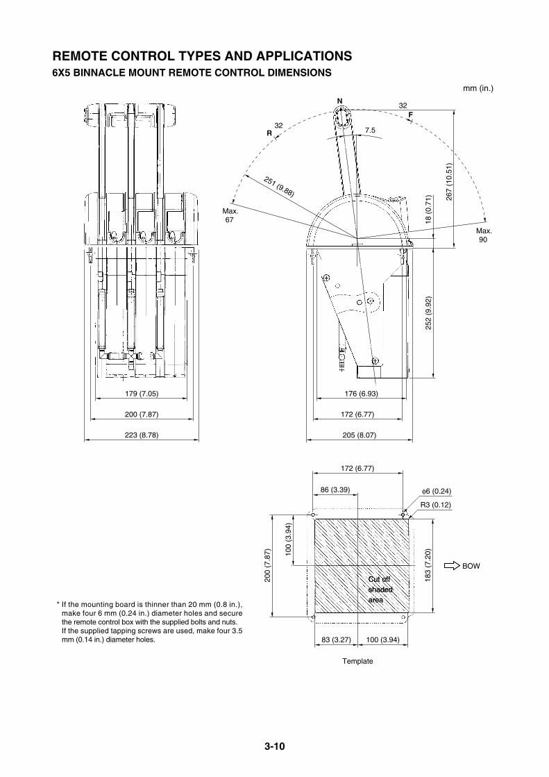
3-10
REMOTE CONTROL TYPES AND APPLICATIONS6X5 BINNACLE MOUNT REMOTE CONTROL DIMENSIONS
205 (8.07)
172 (6.77)
176 (6.93)
200 (7.87)
223 (8.78)
179 (7.05)
100
(3.9
4)
200
(7.8
7)
183
(7.2
0)
172 (6.77)
86 (3.39)
83 (3.27) 100 (3.94)
φ6 (0.24)
R3 (0.12)
251 (9.88)
18 (
0.71
)25
2 (9
.92)
267
(10.
51)
N
32 R
Max.67
Max.90
BOW
F32
7.5
Template
Cut off shaded area
Cut off shaded area
* If the mounting board is thinner than 20 mm (0.8 in.), make four 6 mm (0.24 in.) diameter holes and secure the remote control box with the supplied bolts and nuts. If the supplied tapping screws are used, make four 3.5 mm (0.14 in.) diameter holes.
mm (in.)
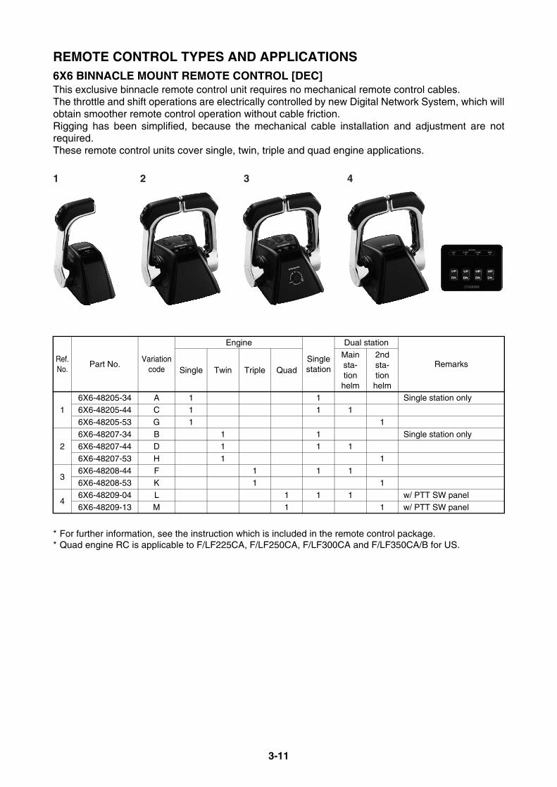
3-11
REMOTE CONTROL TYPES AND APPLICATIONS6X6 BINNACLE MOUNT REMOTE CONTROL [DEC]This exclusive binnacle remote control unit requires no mechanical remote control cables.The throttle and shift operations are electrically controlled by new Digital Network System, which willobtain smoother remote control operation without cable friction.Rigging has been simplified, because the mechanical cable installation and adjustment are notrequired.These remote control units cover single, twin, triple and quad engine applications.
* For further information, see the instruction which is included in the remote control package.* Quad engine RC is applicable to F/LF225CA, F/LF250CA, F/LF300CA and F/LF350CA/B for US.
Ref.No.
Part No.Variation
code
Engine
Single station
Dual station
RemarksSingle Twin Triple Quad
Main sta-tion
helm
2nd sta-tion
helm
16X6-48205-34 A 1 1 Single station only6X6-48205-44 C 1 1 1
6X6-48205-53 G 1 1
26X6-48207-34 B 1 1 Single station only6X6-48207-44 D 1 1 1
6X6-48207-53 H 1 1
36X6-48208-44 F 1 1 16X6-48208-53 K 1 1
46X6-48209-04 L 1 1 1 w/ PTT SW panel
6X6-48209-13 M 1 1 w/ PTT SW panel
1 2 3 4
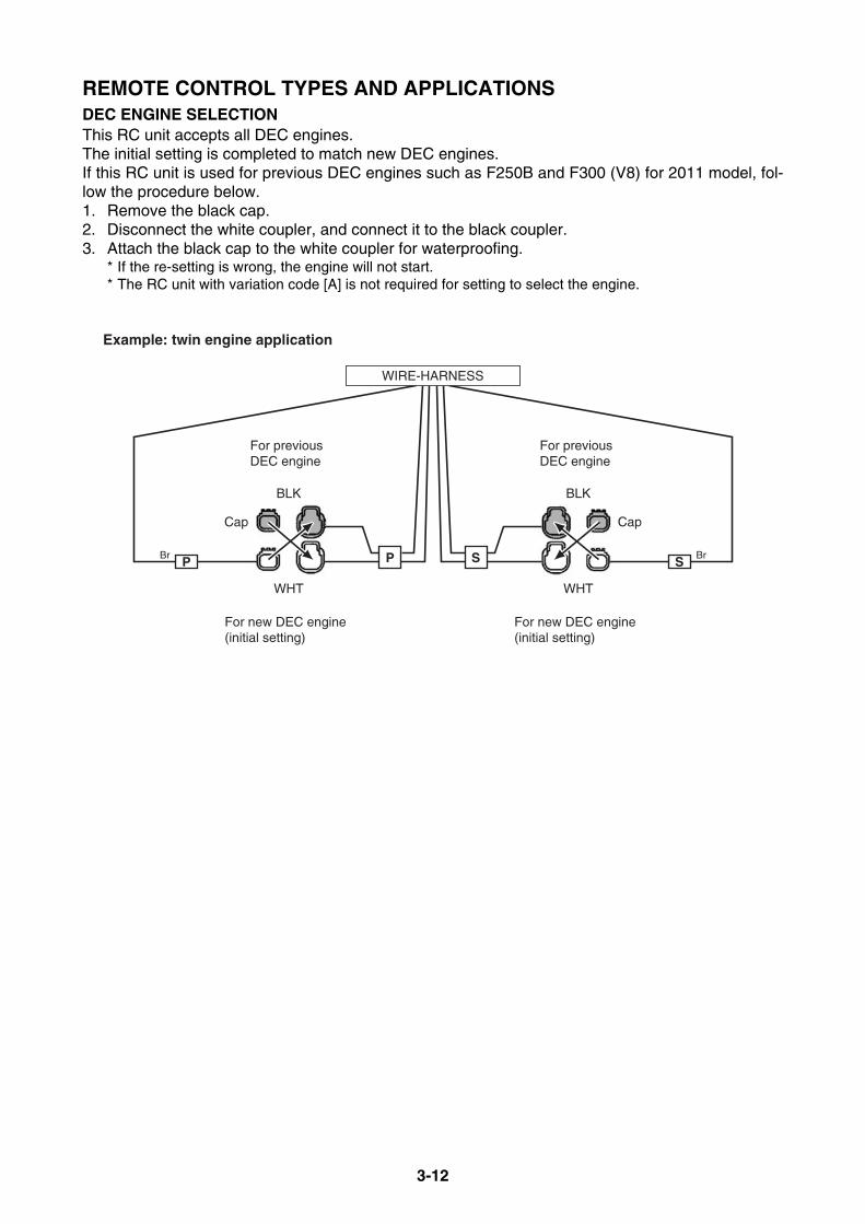
3-12
REMOTE CONTROL TYPES AND APPLICATIONSDEC ENGINE SELECTIONThis RC unit accepts all DEC engines.The initial setting is completed to match new DEC engines.If this RC unit is used for previous DEC engines such as F250B and F300 (V8) for 2011 model, fol-low the procedure below.1. Remove the black cap.2. Disconnect the white coupler, and connect it to the black coupler.3. Attach the black cap to the white coupler for waterproofing.
* If the re-setting is wrong, the engine will not start.* The RC unit with variation code [A] is not required for setting to select the engine.
BLK
WHT
BLK
CapCap
Br Br
For previous DEC engine
For previous DEC engine
For new DEC engine(initial setting)
For new DEC engine(initial setting)
Example: twin engine application
WHT
WIRE-HARNESS
PP SS

3-13
REMOTE CONTROL TYPES AND APPLICATIONS6X6 BINNACLE MOUNT REMOTE CONTROL DIMENSIONSThe side view is the same among all remote control unit variation.
Single engine application
To be continued.
FN
R
Thro
ttle
rang
eThrottle range
5 deg.
Shiftrange
Shiftrange22.5
deg. 22.5deg.
Max. 67 deg.
Max.90 deg.
225
(8.8
6)35
(1.
38)
170
(6.6
9)
128 (5.04)
182 (7.17)
mm (in.)10
6 (4
.17)
Template (single lever)
132 (5.20)
145 (5.71)
59 (
2.32
)
62 (
2.44
)
5.5 (0.22)
Cut out shaded areaCut out shaded area

3-14
REMOTE CONTROL TYPES AND APPLICATIONSTwin engine application
Triple engine application
To be continued.
172
(6.7
7)
Template (twin lever)
132 (5.20)
145 (5.71)
102
(4.0
2)
105
(4.1
3)
5.5 (0.22)
Cut out shaded areaCut out shaded area
mm (in.)
172
(6.7
7)
Template (same as twin engine)
Center RC ECM bracket
* ECM wire harness length: Approx. 1.5 m (5 ft)
132 (5.20)
145 (5.71)
102
(4.0
2)
105
(4.1
3)
5.5 (0.22)
Cut out shaded areCut out shaded areaCut out shaded area
208
(8.1
9)
149
(5.8
7)41
(1.6
1)
116 (4.57)
100 (3.93)
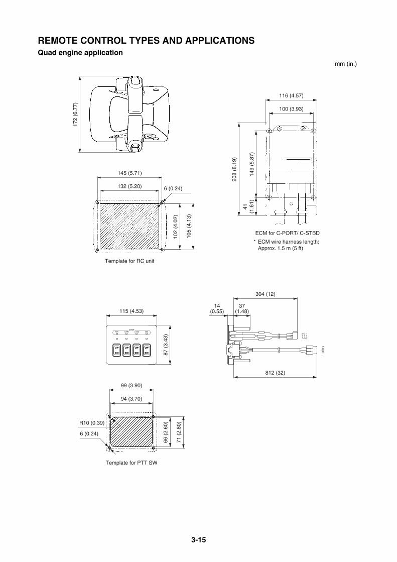
3-15
REMOTE CONTROL TYPES AND APPLICATIONSQuad engine application
208
(8.1
9)
149
(5.8
7)41
(1.6
1)
116 (4.57)
100 (3.93)
ECM for C-PORT/ C-STBD
6 (0.24)132 (5.20)
145 (5.71)
105
(4.1
3)
102
(4.0
2)
172
(6.7
7)
Template for RC unit
6 (0.24)
R10 (0.39)
94 (3.70)
99 (3.90)
115 (4.53)37
(1.48)
304 (12)
14(0.55)
71 (
2.80
)
812 (32)
87 (
3.43
)66
(2.
60)
Template for PTT SW
RL
G
GW PXX XLY Or
* ECM wire harness length: Approx. 1.5 m (5 ft)
mm (in.)
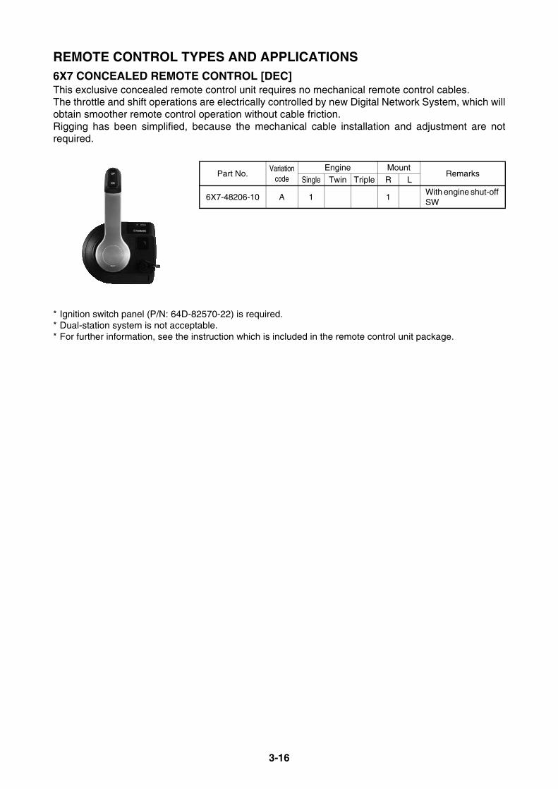
3-16
REMOTE CONTROL TYPES AND APPLICATIONS6X7 CONCEALED REMOTE CONTROL [DEC]This exclusive concealed remote control unit requires no mechanical remote control cables.The throttle and shift operations are electrically controlled by new Digital Network System, which willobtain smoother remote control operation without cable friction.Rigging has been simplified, because the mechanical cable installation and adjustment are notrequired.
* Ignition switch panel (P/N: 64D-82570-22) is required.* Dual-station system is not acceptable.* For further information, see the instruction which is included in the remote control unit package.
Part No.Variation
codeEngine Mount
RemarksSingle Twin Triple R L
6X7-48206-10 A 1 1With engine shut-off SW

3-17
REMOTE CONTROL TYPES AND APPLICATIONS6X7 CONCEALED REMOTE CONTROL DIMENSIONS
213
(8.3
9)
ECM bracket
116 (4.57)
M6
tapp
ing
mou
nt s
crew
F
N
R
Thro
ttle
rang
e
Throttle range
Shift
rangeShift
range22.5
deg.22.5deg.
Max. 67 deg.
Max.90 deg.
Template
* Stop SW wire harness length: Approx. 2 m (6.5 ft)
* ECM wire harness length: Approx. 1.5 m (5 ft)
170
(6.6
9)
130
(5.1
2)155 (6.10)
59.5
(2.
34)
16.5
(0.6
5)40
.5(1
.59)
43(1.69)
56.5 (2.22) 6.4 (0.25)
35 (1.38)
38 (1.50)
54.4(2.14)
Make three 7 mm (9/32 in) holes for mounting with bolts and nuts.Drill 4 mm (5/32 in) holes for tapping screws, if the board is thicker than 20 mm (0.79 in).
12.7
(0.5
0)17
.5(0
.69)
39.5
(1.5
6)
27 (1.06)
57(2.24)
18(0.71)
96.2(3.79)
95 (3.74)
95 (3.74)
95 (3.74)
Mount board
mm (in.)
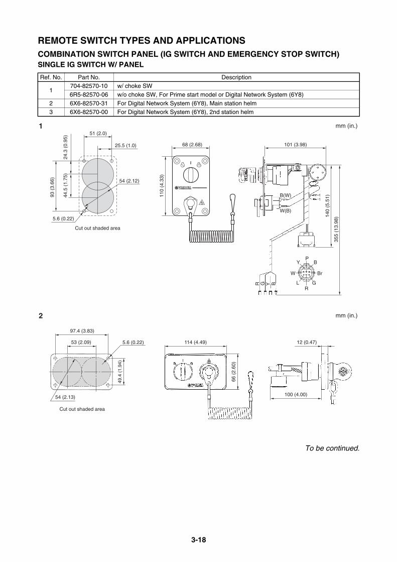
3-18
REMOTE SWITCH TYPES AND APPLICATIONSCOMBINATION SWITCH PANEL (IG SWITCH AND EMERGENCY STOP SWITCH)SINGLE IG SWITCH W/ PANEL
To be continued.
Ref. No. Part No. Description
1704-82570-10 w/ choke SW
6R5-82570-06 w/o choke SW, For Prime start model or Digital Network System (6Y8)
2 6X6-82570-31 For Digital Network System (6Y8), Main station helm3 6X6-82570-00 For Digital Network System (6Y8), 2nd station helm
68 (2.68)
110
(4.3
3)
51 (2.0)
Cut out shaded area
25.5 (1.0)
54 (2.12)
5.6 (0.22)
93 (
3.66
)
44.5
(1.
75)
24.3
(0.
95)
1
2
mm (in.)
mm (in.)
P
R
B
G
Y
LBYGR
BrW
140
(5.5
1)
355
(13.
98)
B(W)
W(B)
66 (
2.60
)
Cut out shaded area
114 (4.49)53 (2.09) 12 (0.47)
97.4 (3.83)
49.4
(1.
94)
54 (2.13)
5.6 (0.22)
100 (4.00)
101 (3.98)

3-19
REMOTE SWITCH TYPES AND APPLICATIONSSINGLE IG SWITCH W/ PANEL
SINGLE IG SWITCH W/O PANEL
Ref. No. Part No. Description
1 704-8257C-01 With choke switch
130
(5.1
2)
Cut out shaded area
51 (2.0)
25.5 (1.0) 68 (2.68)
113
(4.4
9)
24 (
0.94
)24
(0.
94)
52.4 (2.06)
5.5 (0.22) 140
(5.5
1)
86 (3.39)
Or
YBr
P
W
B
3 mm (in.)
20 (0.79)
16 (0.63)
1 mm (in.)
Max. 4 (0.16)
BYGR
140
(5.5
1)
355
(13.
98)
3.5 Nm,0.35 kgf m,2.6 ft lb
B(W)
W(B)
P
R
B
G
Y
L
BrW
Max. 4 (0.16) 101 (3.98)

3-20
REMOTE SWITCH TYPES AND APPLICATIONSTWIN IG SWITCH
To be continued.
Ref. No. Part No. Description
16K1-82570-12 w/ choke SW
61B-82570-05 w/o choke SW
2 6Y8-82570-03 For Digital Network System (6Y8), Main station helm3 6X6-82570-40 For Digital Network System (6Y9), Main station helm
4 6X6-82570-10 For Digital Network System (6Y8), 2nd helm
56X6-82570-60 For Digital Network System (6Y9), main station helm, w/o buzzer, Requires [No.3]6X6-82570-E0 For Digital Network System (6Y9), 2nd station helm, w/ buzzer
128 (5.04)
25.9 (1.02)
54 (2.13)
93 (
3.66
)
24.2
5 (0
.95)
5.6 (0.22)
66 (
2.60
)
Cut out shaded areaCut out shaded areaCut out shaded area
113 (4.45)
25 (0.98)
138 (5.43)
154 (6.06)
50 (
1.97
)
66 (2.60)
54 (2.13)
5.5 (0.22)
Cut out shaded area
*110 (4.33)3.3 (0.13)
*For reference
338
(13.
3)
Cut out shaded area
110
(4.3
3)
B Y G R
145 (5.71) 97 (3.82)
110
(4.3
3)
140
(5.5
1)
340
(13.
39)
P
R
B
G
Y
L
BrW
1
2
mm (in.)
mm (in.)
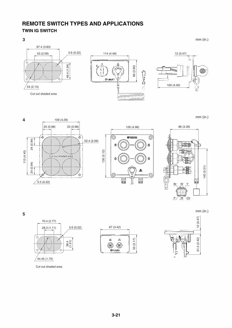
3-21
REMOTE SWITCH TYPES AND APPLICATIONSTWIN IG SWITCH
55 (
2.17
)
Cut out shaded area
87 (3.42)28.3 (1.11)
44.45 (1.75)
70.4 (2.77)
5.6 (0.22)
61.5
(2.
42)
12 (
0.47
)
38.4
(1.5
1)
Cut out shaded area
130
(5.1
2)
109 (4.29)
25 (0.98) 25 (0.98) 126 (4.96)
113
(4.4
5)
24 (
0.94
)24
(0.
94)
52.4 (2.06)
5.5 (0.22)
140
(5.5
1)
86 (3.39)
Or
YBr
P
W
B
Cut out shaded areaCut out shaded areaCut out shaded area
66 (
2.60
)
Cut out shaded area
114 (4.49)53 (2.09) 12 (0.47)
97.4 (3.83)
49.4
(1.
94)
54 (2.13)
5.6 (0.22)
100 (4.00)
3
4
5
mm (in.)
mm (in.)
mm (in.)
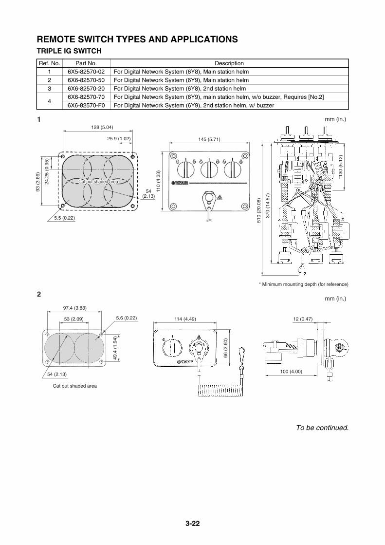
3-22
REMOTE SWITCH TYPES AND APPLICATIONSTRIPLE IG SWITCH
To be continued.
Ref. No. Part No. Description1 6X5-82570-02 For Digital Network System (6Y8), Main station helm
2 6X6-82570-50 For Digital Network System (6Y9), Main station helm
3 6X6-82570-20 For Digital Network System (6Y8), 2nd station helm
46X6-82570-70 For Digital Network System (6Y9), main station helm, w/o buzzer, Requires [No.2]
6X6-82570-F0 For Digital Network System (6Y9), 2nd station helm, w/ buzzer
Cut out shaded areaCut out shaded areaCut out shaded area
128 (5.04)
25.9 (1.02)
24.2
5 (0
.95)
93 (
3.66
)
54(2.13)
5.5 (0.22)
110
(4.3
3)
145 (5.71)
510
(20.
08)
370
(14.
57)
*130
(5.
12)
* Minimum mounting depth (for reference)
Cut out shaded area
1
2
mm (in.)
mm (in.)
66 (
2.60
)
Cut out shaded area
114 (4.49)53 (2.09) 12 (0.47)
97.4 (3.83)
49.4
(1.
94)
54 (2.13)
5.6 (0.22)
100 (4.00)

3-23
REMOTE SWITCH TYPES AND APPLICATIONSTRIPLE IG SWITCH
Cut out shaded area
130
(5.1
2)
184 (7.24)
Cut out shaded areaCut out shaded areaCut out shaded area
167 (6.57)
25 (0.98) 25 (0.98)
113
(4.4
5)
24 (
0.94
)24
(0.
94) 52.4
(2.06)
5.5 (0.22)
mm (in.)
140
(5.5
1)
86 (3.39)
Or
YBr
P
W
B
3
4 mm (in.)
55 (
2.17
)
Cut out shaded area
114 (4.49) 55.2 (2.17)
97.4 (3.83)
5.6 (0.22)
61.5
(2.
42)
12 (
0.47
)
38.4
(1.5
1)
44.45 (1.75)
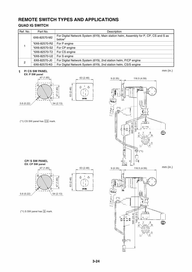
3-24
REMOTE SWITCH TYPES AND APPLICATIONSQUAD IG SWITCH
Ref. No. Part No. Description
1
6X6-82570-M2For Digital Network System (6Y9), Main station helm, Assembly for P, CP, CS and S as below*
*6X6-82570-R2 For P engine
*6X6-82570-S2 For CP engine
*6X6-82570-T2 For CS engine*6X6-82570-U2 For S engine
26X6-82570-J0 For Digital Network System (6Y9), 2nd station helm, P/CP engine
6X6-82570-K0 For Digital Network System (6Y9), 2nd station helm, CS/S engine
163
(2.4
8)
63 (2.48)47 (1.85)
47 (1
.85)
5.6 (0.22) 54 (2.13)
P/ CS SW PANELEX: P SW panel
(*1) CS SW panel has CS mark.
63 (2
.48)
63 (2.48)47 (1.85)
5.6 (0.22) 54 (2.13)
47 (1
.85)
CP/ S SW PANELEX: CP SW panel
(*1) S SW panel has S mark.
mm (in.)
mm (in.)
116.5 (4.59)9 (0.35)
140
(5.5
1)66
5 (2
6.2)
(*1)
(*1)
R Y
BrBYP
W
L
B Y R
GR
116.5 (4.59)9 (0.35)
140
(5.5
1)59
5 (2
3.4)
R G
BrBYP
W
LG
R
Y R
(*1)
(*1)
B W
B W

3-25
REMOTE SWITCH TYPES AND APPLICATIONSQUAD IG SWITCH
2 mm (in.)EX: P/CP SW panel
450 (17.7) 12 (0.47)
5.6 (0.22)
87 (3.43)
61.5 (2.42)
28.3 (1.11)
70.4 (2.77)
55 (
2.17
)38
.4(1
.51)
44.5 (1.75)
The recognition letter such as P, CP, S, CS is stamped on the surface protection film.
Cut out shaded area
P BrL/W Y
L/W YP Br
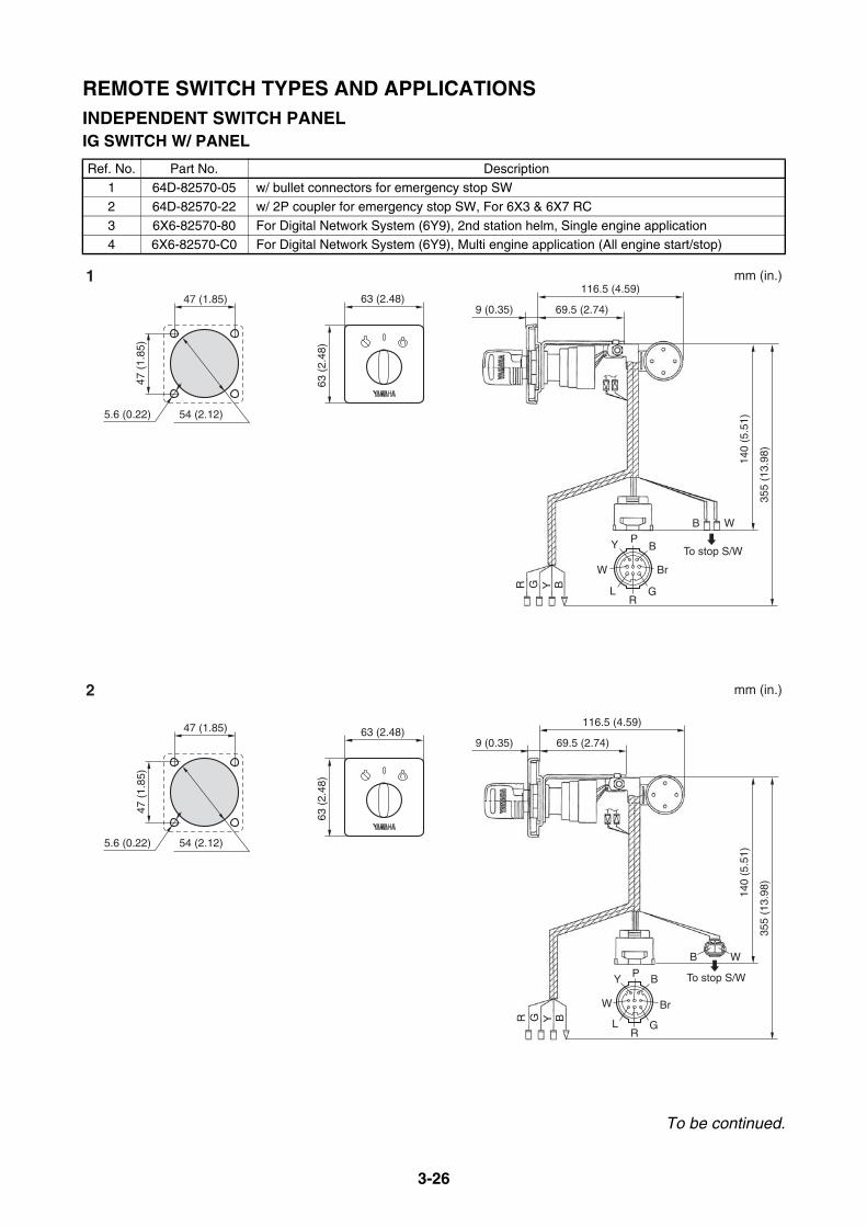
3-26
REMOTE SWITCH TYPES AND APPLICATIONSINDEPENDENT SWITCH PANELIG SWITCH W/ PANEL
To be continued.
Ref. No. Part No. Description1 64D-82570-05 w/ bullet connectors for emergency stop SW
2 64D-82570-22 w/ 2P coupler for emergency stop SW, For 6X3 & 6X7 RC
3 6X6-82570-80 For Digital Network System (6Y9), 2nd station helm, Single engine application4 6X6-82570-C0 For Digital Network System (6Y9), Multi engine application (All engine start/stop)
63 (2.48)
63 (
2.48
)
47 (1.85)
47 (
1.85
)
54 (2.12)5.6 (0.22)
63 (2.48)
63 (
2.48
)
47 (1.85)
47 (
1.85
)
54 (2.12)5.6 (0.22)
116.5 (4.59)
69.5 (2.74)9 (0.35)
P
R
B
G
Y
L
BYGR
BYGR
BrW
140
(5.5
1)
355
(13.
98)
B
To stop S/W
W
116.5 (4.59)
69.5 (2.74)9 (0.35)
P
R
B
G
Y
L
BrW
140
(5.5
1)
355
(13.
98)
B W
To stop S/W
1
2
mm (in.)
mm (in.)
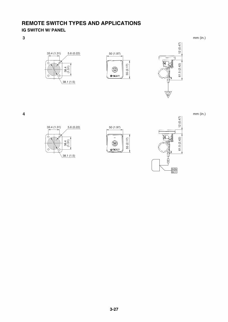
3-27
REMOTE SWITCH TYPES AND APPLICATIONSIG SWITCH W/ PANEL
55 (
2.17
)
50 (1.97)33.4 (1.31) 5.6 (0.22)
61.5
(2.
42)
12 (
0.47
)
38.4
(1.5
1)
38.1 (1.5)
55 (
2.17
)50 (1.97)33.4 (1.31) 5.6 (0.22)
61.5
(2.
42)
12 (
0.47
)
38.4
(1.5
1)
38.1 (1.5)
Br YBrBr
BrPY
3
4
mm (in.)
mm (in.)
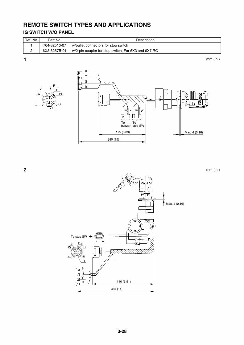
3-28
REMOTE SWITCH TYPES AND APPLICATIONSIG SWITCH W/O PANEL
Ref. No. Part No. Description1 704-82510-07 w/bullet connectors for stop switch
2 6X3-8257B-01 w/2-pin coupler for stop switch, For 6X3 and 6X7 RC
YP
BW
L
Br
GR
380 (15)
175 (6.89)
R
Y
G
B
P Y B W
To stop SW
To buzzer
355 (14)
140 (5.51)
B
G
Y
R
P BBr
G
R
YW
L
B W
To stop SW
Max. 4 (0.16)
Max. 4 (0.16)
1
2
mm (in.)
mm (in.)
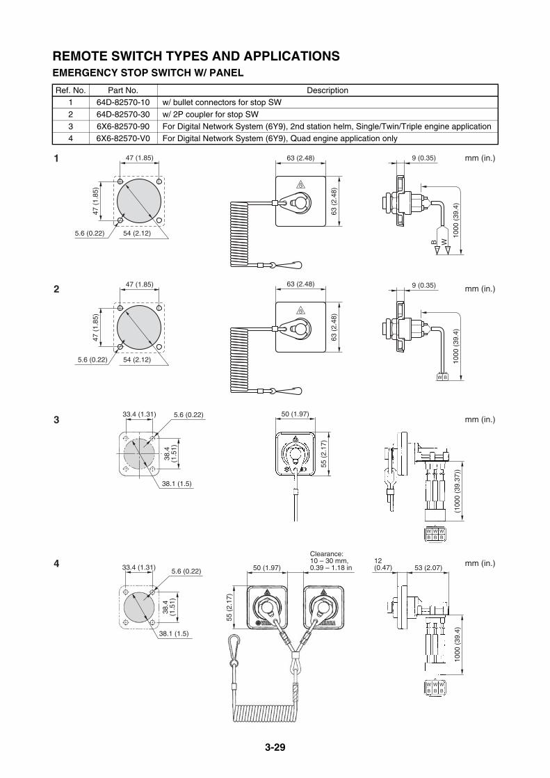
3-29
REMOTE SWITCH TYPES AND APPLICATIONSEMERGENCY STOP SWITCH W/ PANEL
Ref. No. Part No. Description1 64D-82570-10 w/ bullet connectors for stop SW
2 64D-82570-30 w/ 2P coupler for stop SW
3 6X6-82570-90 For Digital Network System (6Y9), 2nd station helm, Single/Twin/Triple engine application4 6X6-82570-V0 For Digital Network System (6Y9), Quad engine application only
63 (2.48)
63 (
2.48
)
9 (0.35)
WB
1000
(39
.4)
47 (1.85)
47 (
1.85
)
54 (2.12)5.6 (0.22)
63 (2.48)
63 (
2.48
)
9 (0.35)
1000
(39
.4)
47 (1.85)
47 (
1.85
)
54 (2.12)5.6 (0.22)
BW
1
2
3
4
mm (in.)
mm (in.)
mm (in.)
mm (in.)Clearance:10 – 30 mm,0.39 – 1.18 in 53 (2.07)
1000
(39
.4)
12(0.47)
55 (
2.17
)
50 (1.97)
38.1 (1.5)
33.4 (1.31) 5.6 (0.22)
38.4
(1.5
1)
W W WB B B
W W WB B B
55 (
2.17
)
38.1 (1.5)
50 (1.97)33.4 (1.31) 5.6 (0.22)
(100
0 (3
9.37
))
38.4
(1.5
1)

3-30
REMOTE SWITCH TYPES AND APPLICATIONSEMERGENCY STOP SWITCH W/O PANEL
Ref. No. Part No. Description1 688-82575-10 w/bullet connectors for stop switch
2 64D-82575-10 w/2-pin coupler for stop switch
WB
250
(9.8
4)
16 (0.63)
1000
(39
.4)
16 (0.63)
Max. 4 (0.16)Max. 4 (0.16)
BW
1 2mm (in.)mm (in.)
3.5 Nm,0.35 kgf•m,2.6 ft•lb
3.5 Nm,0.35 kgf•m,2.6 ft•lb
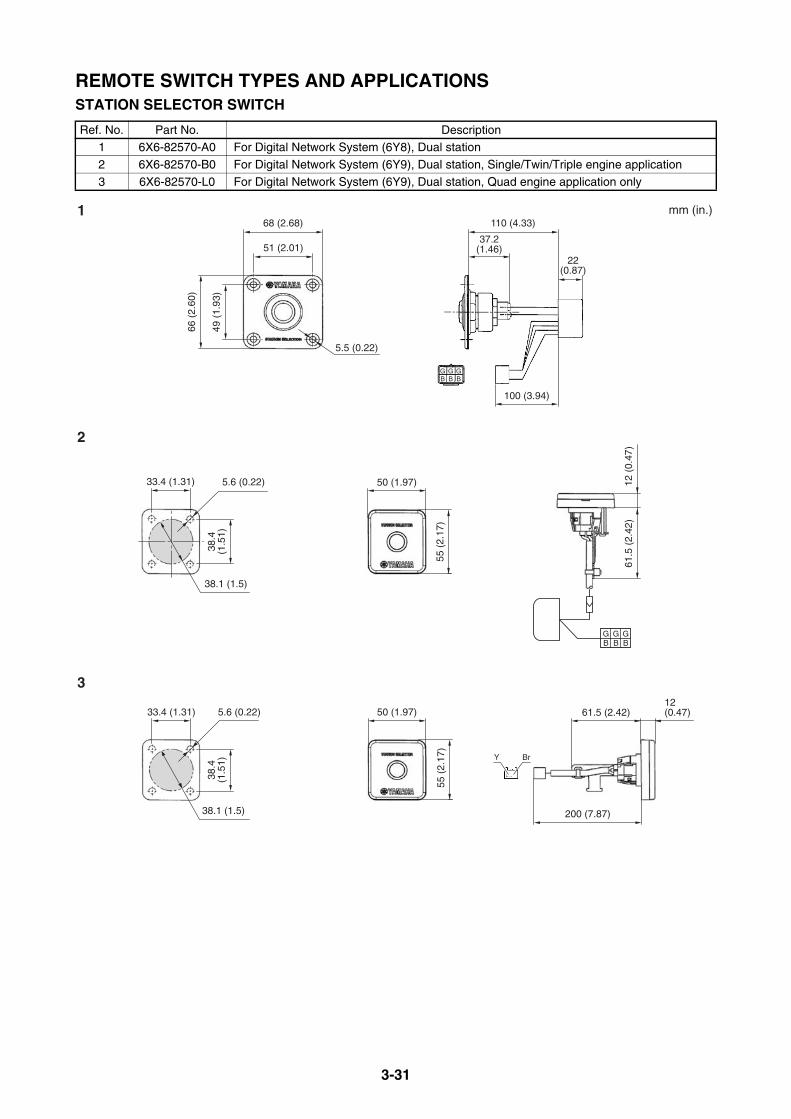
3-31
REMOTE SWITCH TYPES AND APPLICATIONSSTATION SELECTOR SWITCH
Ref. No. Part No. Description1 6X6-82570-A0 For Digital Network System (6Y8), Dual station
2 6X6-82570-B0 For Digital Network System (6Y9), Dual station, Single/Twin/Triple engine application
3 6X6-82570-L0 For Digital Network System (6Y9), Dual station, Quad engine application only
1
2
3
mm (in.)
B B BGGG
66 (
2.60
)
49 (
1.93
)68 (2.68)
51 (2.01)
5.5 (0.22)
110 (4.33)
100 (3.94)
G G GB B B
37.2(1.46)
22(0.87)
61.5
(2.
42)
12 (
0.47
)
55 (
2.17
)
38.1 (1.5)
50 (1.97)33.4 (1.31) 5.6 (0.22)
38.4
(1.5
1)
200 (7.87)
61.5 (2.42)12(0.47)
55 (
2.17
)
50 (1.97)
38.1 (1.5)
33.4 (1.31) 5.6 (0.22)
38.4
(1.5
1)
Y Br
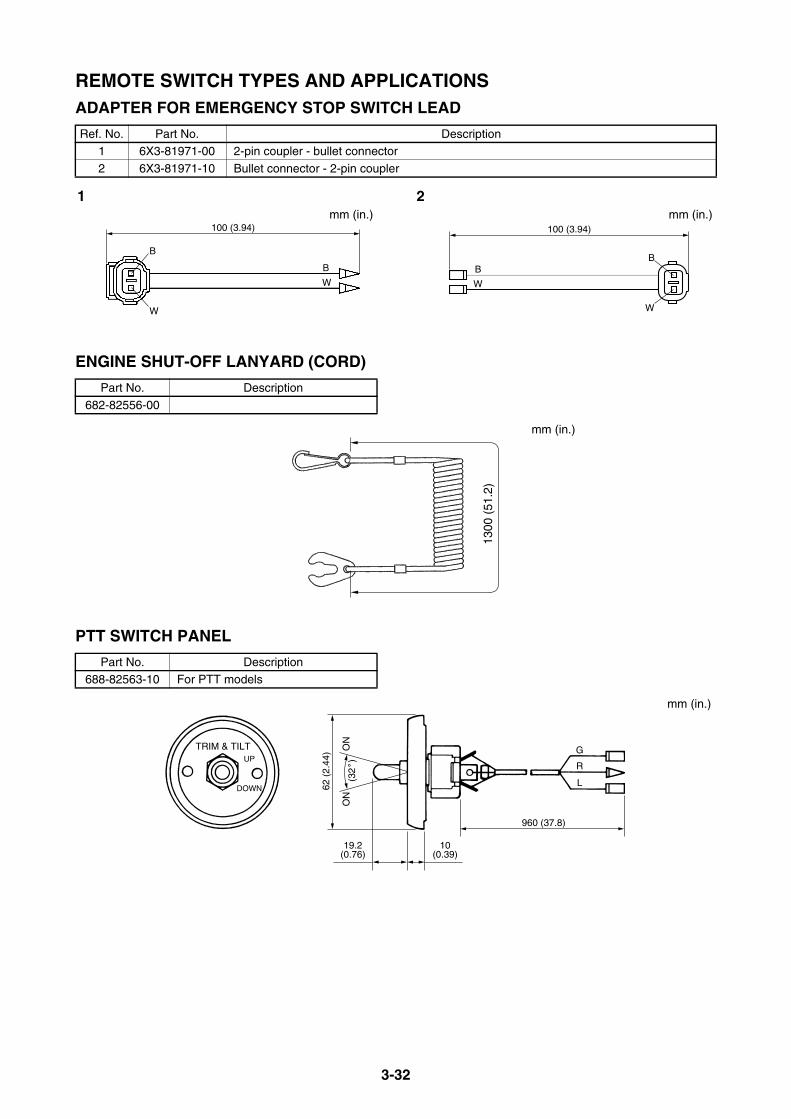
3-32
REMOTE SWITCH TYPES AND APPLICATIONSADAPTER FOR EMERGENCY STOP SWITCH LEAD
ENGINE SHUT-OFF LANYARD (CORD)
PTT SWITCH PANEL
Ref. No. Part No. Description1 6X3-81971-00 2-pin coupler - bullet connector
2 6X3-81971-10 Bullet connector - 2-pin coupler
Part No. Description
682-82556-00
Part No. Description688-82563-10 For PTT models
100 (3.94)
B
W
100 (3.94)
B
W
B
WW
B
1 2mm (in.)mm (in.)
1300
(51
.2)
mm (in.)
G
R
L
960 (37.8)
10(0.39)
19.2(0.76)
TRIM & TILTUP
DOWN 62 (
2.44
)
ON
ON
(32
)
mm (in.)
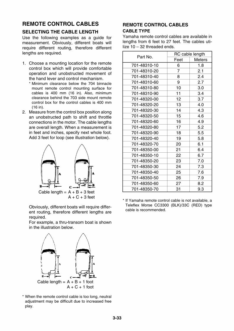
3-33
REMOTE CONTROL CABLESSELECTING THE CABLE LENGTHUse the following examples as a guide formeasurement. Obviously, different boats willrequire different routing, therefore differentlengths are required.
1. Choose a mounting location for the remotecontrol box which will provide comfortableoperation and unobstructed movement ofthe hand lever and control mechanism.* Minimum clearance below the 704 binnacle
mount remote control mounting surface forcables is 400 mm (16 in). Also, minimumclearance behind the 703 side mount remotecontrol box for the control cables is 400 mm(16 in).
2. Measure from the control box position alongan unobstructed path to shift and throttleconnections in the motor. The cable lengthsare overall length. When a measurement isin feet and inches, specify next whole foot.Add 3 feet for loop (see illustration below).
Obviously, different boats will require differ-ent routing, therefore different lengths arerequired. For example, a thru-transom boat is shownin the illustration below.
* When the remote control cable is too long, neutraladjustment may be difficult due to increased freeplay.
REMOTE CONTROL CABLESCABLE TYPEYamaha remote control cables are available inlengths from 6 feet to 27 feet. The cables uti-lize 10 – 32 threaded ends.
* If Yamaha remote control cable is not available, aTeleflex Morse CC3300 (BLK)/33C (RED) typecable is recommended.
Cable length = A + B + 3 feetA + C + 3 feet
Cable length = A + B + 1 footA + C + 1 foot
Part No.RC cable lengthFeet Meters
701-48310-10 6 1.8701-48310-20 7 2.1701-48310-40 8 2.4701-48310-60 9 2.7701-48310-80 10 3.0701-48310-90 11 3.4701-48320-00 12 3.7701-48320-20 13 4.0701-48320-30 14 4.3701-48320-50 15 4.6701-48320-60 16 4.9701-48320-80 17 5.2701-48320-90 18 5.5701-48320-40 19 5.8701-48320-70 20 6.1701-48350-00 21 6.4701-48350-10 22 6.7701-48350-20 23 7.0701-48350-30 24 7.3701-48350-40 25 7.6701-48350-50 26 7.9701-48350-60 27 8.2701-48350-70 31 9.3
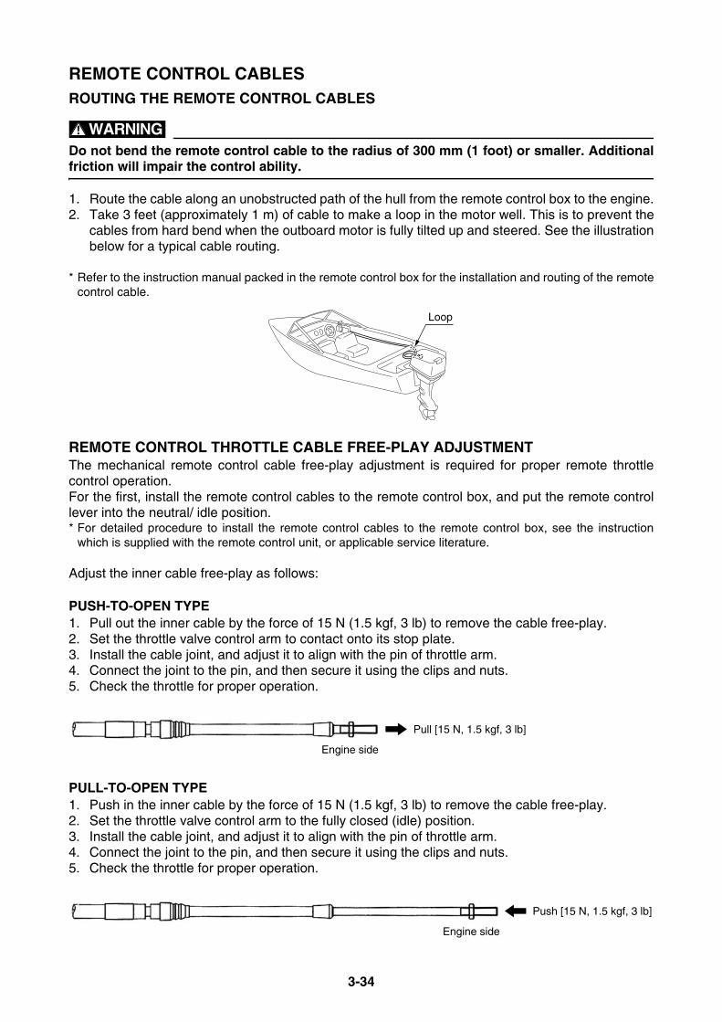
3-34
REMOTE CONTROL CABLESROUTING THE REMOTE CONTROL CABLES
WARNINGDo not bend the remote control cable to the radius of 300 mm (1 foot) or smaller. Additionalfriction will impair the control ability.
1. Route the cable along an unobstructed path of the hull from the remote control box to the engine.2. Take 3 feet (approximately 1 m) of cable to make a loop in the motor well. This is to prevent the
cables from hard bend when the outboard motor is fully tilted up and steered. See the illustrationbelow for a typical cable routing.
* Refer to the instruction manual packed in the remote control box for the installation and routing of the remotecontrol cable.
REMOTE CONTROL THROTTLE CABLE FREE-PLAY ADJUSTMENTThe mechanical remote control cable free-play adjustment is required for proper remote throttlecontrol operation.For the first, install the remote control cables to the remote control box, and put the remote controllever into the neutral/ idle position.* For detailed procedure to install the remote control cables to the remote control box, see the instruction
which is supplied with the remote control unit, or applicable service literature.
Adjust the inner cable free-play as follows:
PUSH-TO-OPEN TYPE1. Pull out the inner cable by the force of 15 N (1.5 kgf, 3 lb) to remove the cable free-play.2. Set the throttle valve control arm to contact onto its stop plate.3. Install the cable joint, and adjust it to align with the pin of throttle arm.4. Connect the joint to the pin, and then secure it using the clips and nuts.5. Check the throttle for proper operation.
PULL-TO-OPEN TYPE1. Push in the inner cable by the force of 15 N (1.5 kgf, 3 lb) to remove the cable free-play.2. Set the throttle valve control arm to the fully closed (idle) position.3. Install the cable joint, and adjust it to align with the pin of throttle arm.4. Connect the joint to the pin, and then secure it using the clips and nuts.5. Check the throttle for proper operation.
Loop
Pull [15 N, 1.5 kgf, 3 lb]
Engine side
Push [15 N, 1.5 kgf, 3 lb]
Engine side
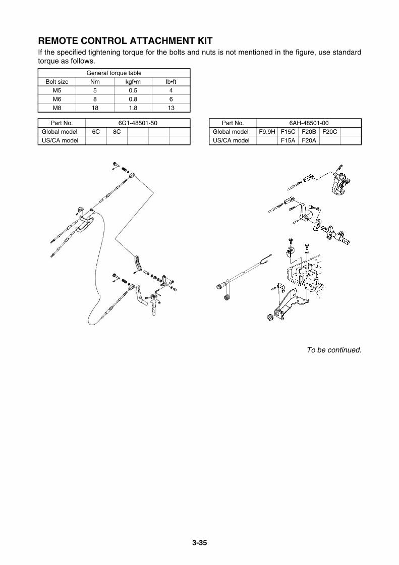
3-35
REMOTE CONTROL ATTACHMENT KITIf the specified tightening torque for the bolts and nuts is not mentioned in the figure, use standardtorque as follows.
To be continued.
General torque table
Bolt size Nm kgf•m lb•ftM5 5 0.5 4
M6 8 0.8 6
M8 18 1.8 13
Part No. 6G1-48501-50Global model 6C 8C
US/CA model
Part No. 6AH-48501-00Global model F9.9H F15C F20B F20C
US/CA model F15A F20A
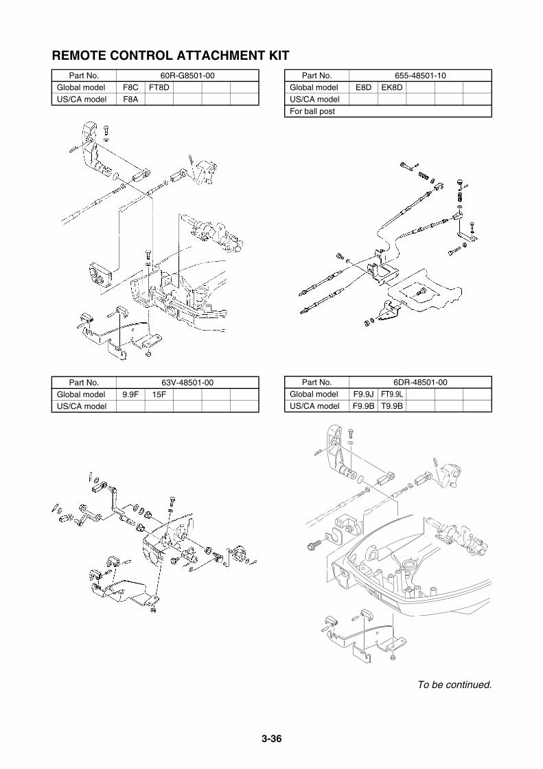
3-36
REMOTE CONTROL ATTACHMENT KIT
To be continued.
Part No. 60R-G8501-00Global model F8C FT8D
US/CA model F8A
Part No. 63V-48501-00
Global model 9.9F 15FUS/CA model
Part No. 655-48501-10Global model E8D EK8D
US/CA model
For ball post
Part No. 6DR-48501-00Global model F9.9J FT9.9L
US/CA model F9.9B T9.9B

3-37
REMOTE CONTROL ATTACHMENT KIT
To be continued.
Part No. 6BL-48501-00Global model F25D
US/CA model F25A
Part No. 6L2-48501-11Global model 20D 25N
US/CA model
Part No. 689-48501-21-4DGlobal model E/25B 25X E/30H
US/CA model
For ball post/ STR guide
Part No. 6J8-48501-03
Global model 30D
US/CA model

3-38
REMOTE CONTROL ATTACHMENT KITPart No. 66T-48501-01
Global model E/40X
US/CA model
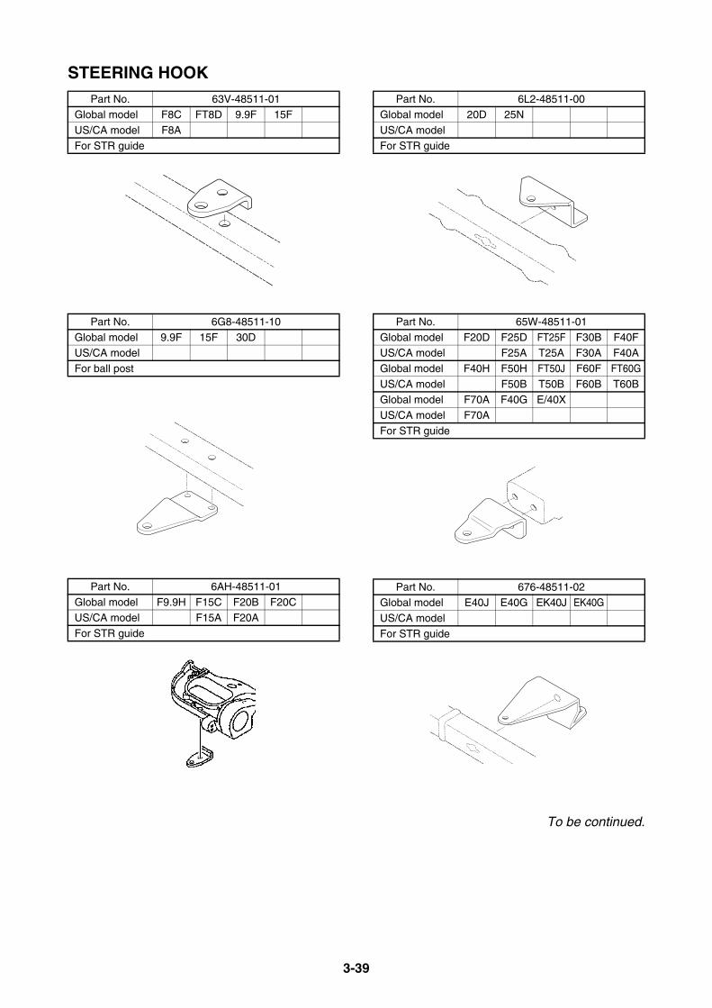
3-39
STEERING HOOK
To be continued.
Part No. 63V-48511-01Global model F8C FT8D 9.9F 15F
US/CA model F8A
For STR guide
Part No. 6G8-48511-10
Global model 9.9F 15F 30DUS/CA model
For ball post
Part No. 6AH-48511-01
Global model F9.9H F15C F20B F20CUS/CA model F15A F20A
For STR guide
Part No. 6L2-48511-00Global model 20D 25N
US/CA model
For STR guide
Part No. 65W-48511-01
Global model F20D F25D FT25F F30B F40FUS/CA model F25A T25A F30A F40A
Global model F40H F50H FT50J F60F FT60G
US/CA model F50B T50B F60B T60BGlobal model F70A F40G E/40X
US/CA model F70A
For STR guide
Part No. 676-48511-02Global model E40J E40G EK40J EK40G
US/CA model
For STR guide
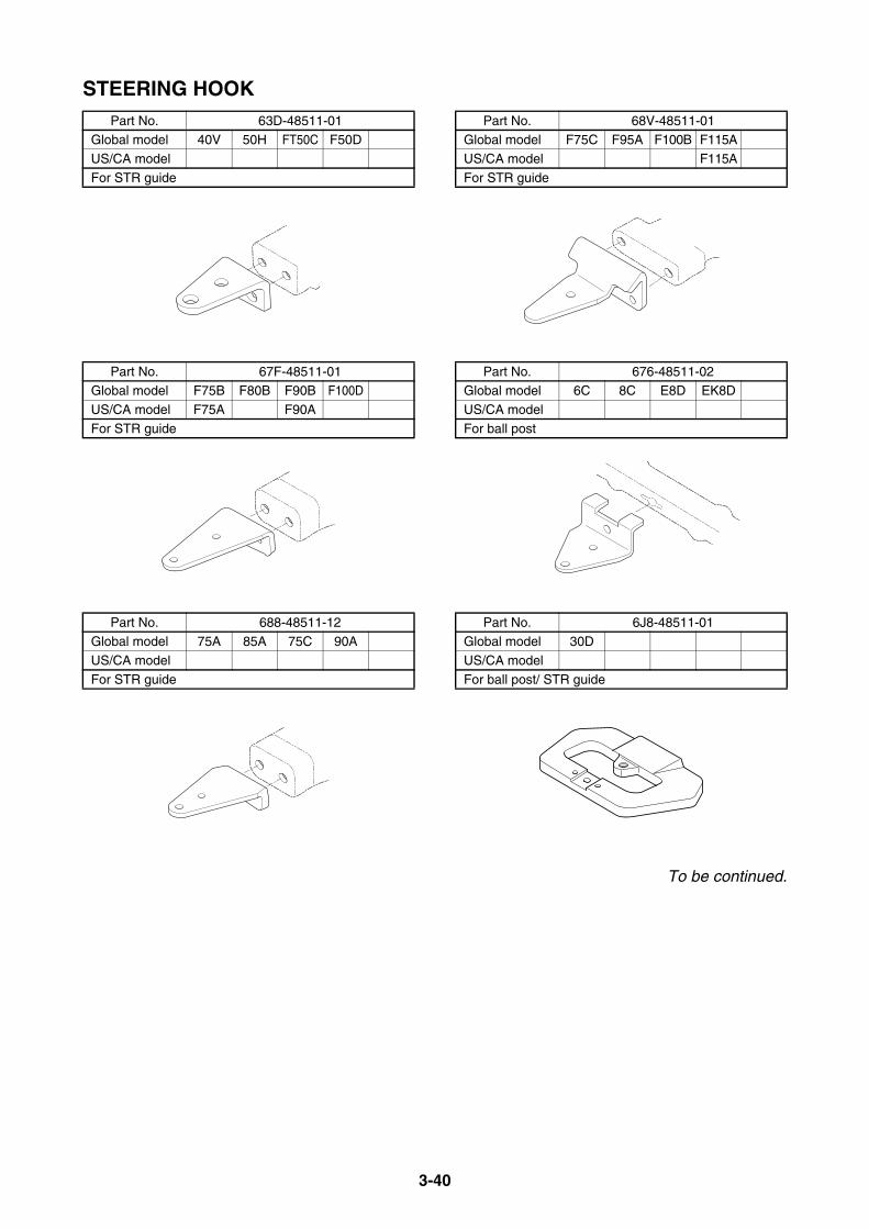
3-40
STEERING HOOK
To be continued.
Part No. 63D-48511-01Global model 40V 50H FT50C F50D
US/CA model
For STR guide
Part No. 67F-48511-01Global model F75B F80B F90B F100D
US/CA model F75A F90A
For STR guide
Part No. 688-48511-12Global model 75A 85A 75C 90A
US/CA model
For STR guide
Part No. 68V-48511-01Global model F75C F95A F100B F115A
US/CA model F115A
For STR guide
Part No. 676-48511-02Global model 6C 8C E8D EK8D
US/CA model
For ball post
Part No. 6J8-48511-01Global model 30D
US/CA model
For ball post/ STR guide
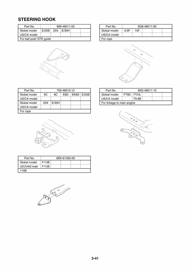
3-41
STEERING HOOKPart No. 689-48511-02
Global model E/25B 25X E/30H
US/CA model
For ball post/ STR guide
Part No. 700-48510-12
Global model 6C 8C E8D EK8D E/25B
US/CA modelGlobal model 25X E/30H
US/CA model
For rope
Part No. 6EK-61350-00Global model F115B
US/CA/ANZ model F115B
115B
Part No. 6G8-48511-00Global model 9.9F 15F
US/CA model
For rope
Part No. 69G-48511-10
Global model FT8D FT9.9L
US/CA model T9.9BFor linkage to main engine
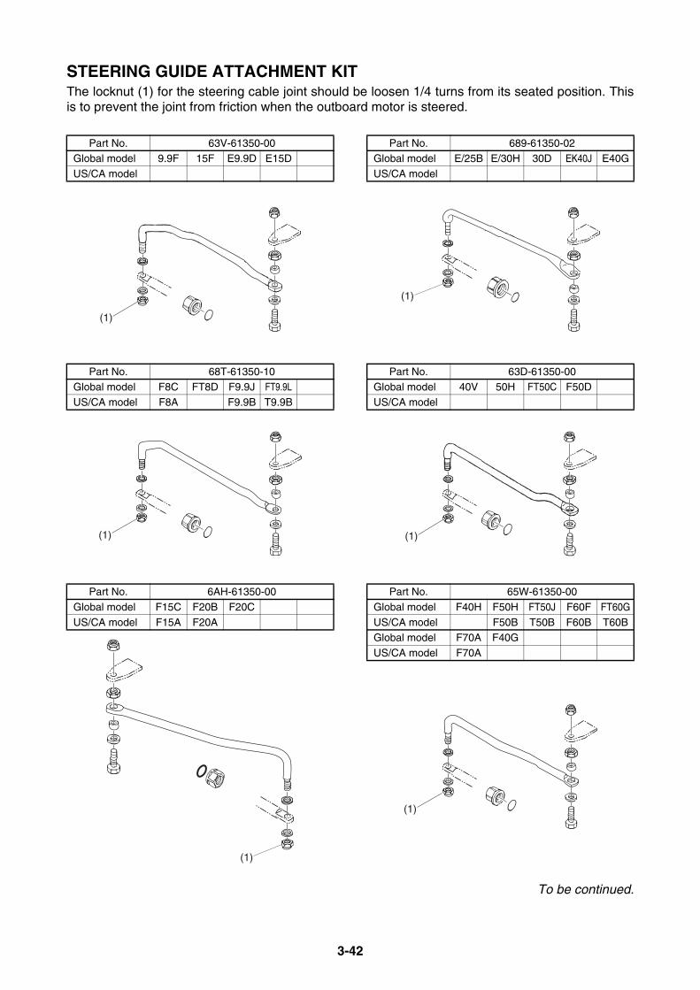
3-42
STEERING GUIDE ATTACHMENT KITThe locknut (1) for the steering cable joint should be loosen 1/4 turns from its seated position. Thisis to prevent the joint from friction when the outboard motor is steered.
To be continued.
Part No. 63V-61350-00Global model 9.9F 15F E9.9D E15D
US/CA model
Part No. 68T-61350-10Global model F8C FT8D F9.9J FT9.9L
US/CA model F8A F9.9B T9.9B
Part No. 6AH-61350-00
Global model F15C F20B F20C
US/CA model F15A F20A
(1)
(1)
(1)
Part No. 689-61350-02Global model E/25B E/30H 30D EK40J E40G
US/CA model
Part No. 63D-61350-00Global model 40V 50H FT50C F50D
US/CA model
Part No. 65W-61350-00
Global model F40H F50H FT50J F60F FT60G
US/CA model F50B T50B F60B T60BGlobal model F70A F40G
US/CA model F70A
(1)
(1)
(1)
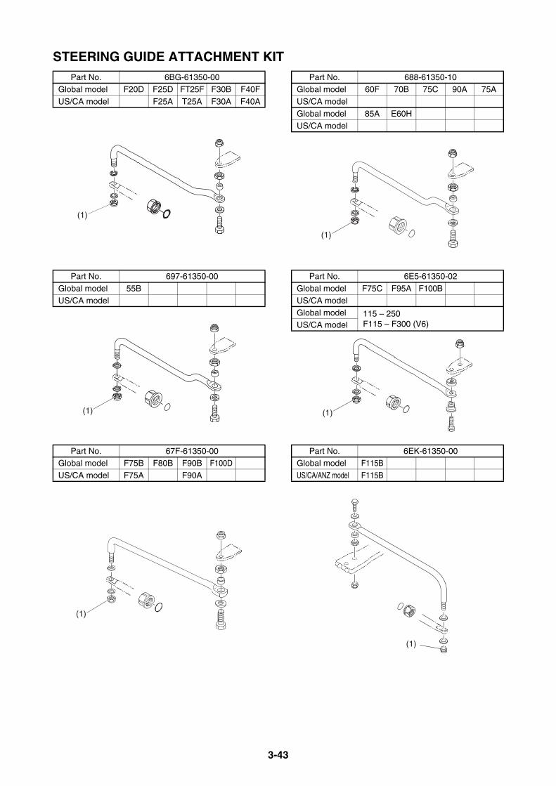
3-43
STEERING GUIDE ATTACHMENT KITPart No. 6BG-61350-00
Global model F20D F25D FT25F F30B F40F
US/CA model F25A T25A F30A F40A
Part No. 697-61350-00
Global model 55BUS/CA model
Part No. 67F-61350-00Global model F75B F80B F90B F100D
US/CA model F75A F90A
(1)
(1)
(1)
Part No. 688-61350-10Global model 60F 70B 75C 90A 75A
US/CA model
Global model 85A E60HUS/CA model
Part No. 6E5-61350-02
Global model F75C F95A F100BUS/CA model
Global model 115 – 250F115 – F300 (V6)US/CA model
Part No. 6EK-61350-00Global model F115B
US/CA/ANZ model F115B
(1)
(1)
(1)

3-44
TIE-BAR KITThis kit is used to link the 2 engines in twinengine application.Adjustable distance: 600 mm (23.6 in) – 800 mm (31.5 in)
Part No. 6E5-61301-01
Global model 40 – 250F30 – F300 (V6)US/CA/ANZ model

3-45
CONVENTIONAL WIRE HARNESSAn optional wire-harness for the remote controlis available. This will help set up the remotecontrol equipment on any boats. Choose asuitable wire-harness if necessary. For the wire color code description, see thetable on page 5-36.
SWITCH PANEL HARNESS7-PIN MAIN HARNESS
10-PIN MAIN HARNESS
7- TO 10-PIN ADAPTER
MAIN HARNESS EXTENSION7-PIN EXTENSION HARNESS
10-PIN EXTENSION HARNESS
Part No. Length (L) Remarks
688-82586-50 5 m (16 ft) Without PTT
Part No. Length (L) Remarks688-8258A-50 5 m (16 ft)
688-8258A-60 6 m (19 ft)
688-8258A-70 7 m (23 ft)6K1-8258A-40 8 m (26 ft)
61B-8258A-01 9.5 m (32 ft)
L
PG
Br W
RB
PW
LR
To S/Wpanel
G
Br
B
(L)
RYG
Lg
PBrB
LW
SbP
W
LRG
BrB Y
R
R
Sb Lg
Br
BBr
To S/Wpanel
To 704/6X3RC box
(L)
Part No. Length (L) Remarks703-8258A-00 0.5 m (2 ft)
Part No. Length (L) Remarks688-82586-11 2 m (7 ft)
688-82586-31 3 m (10 ft)
Part No. Length (L) Remarks688-8258A-10 2 m (7 ft)
688-8258A-30 3 m (10 ft)
L
PG
Br W
RB
Sb
YRGP
BrB L
W
(L)RCENG
L
PG
Br W
RB
L
RG
W Br
PB
(L)
Lg
BrB
LW
SbY
RG
P
(L)
RG Y
Sb
W
LBBr
Lg
P
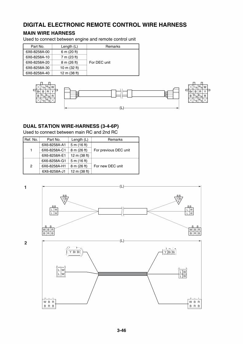
3-46
DIGITAL ELECTRONIC REMOTE CONTROL WIRE HARNESSMAIN WIRE HARNESSUsed to connect between engine and remote control unit
DUAL STATION WIRE-HARNESS (3-4-6P)Used to connect between main RC and 2nd RC
Part No. Length (L) Remarks
6X6-8258A-00 6 m (20 ft)
For DEC unit6X6-8258A-10 7 m (23 ft)6X6-8258A-20 8 m (26 ft)
6X6-8258A-30 10 m (32 ft)
6X6-8258A-40 12 m (38 ft)
Ref. No. Part No. Length (L) Remarks
16X6-8258A-A1 5 m (16 ft)
For previous DEC unit6X6-8258A-C1 8 m (26 ft)
6X6-8258A-E1 12 m (38 ft)
26X6-8258A-G1 5 m (16 ft)
For new DEC unit6X6-8258A-H1 8 m (26 ft)
6X6-8258A-J1 12 m (38 ft)
(L)
B R
L B
R W
W B
W R W
Y
RB
Br
L R
B W
B R
L B
R W
W B
W R W
Y
RB
Br
L R
B W
B R BRBW
B R BRBW
L W
L W
L W
L W
BrX
Y BrX
Y
(L)1
LL
W
Y Br Br
WLL
W
Y Br Br
W
WB
BR
RB
WB
BR
RB
(L)2
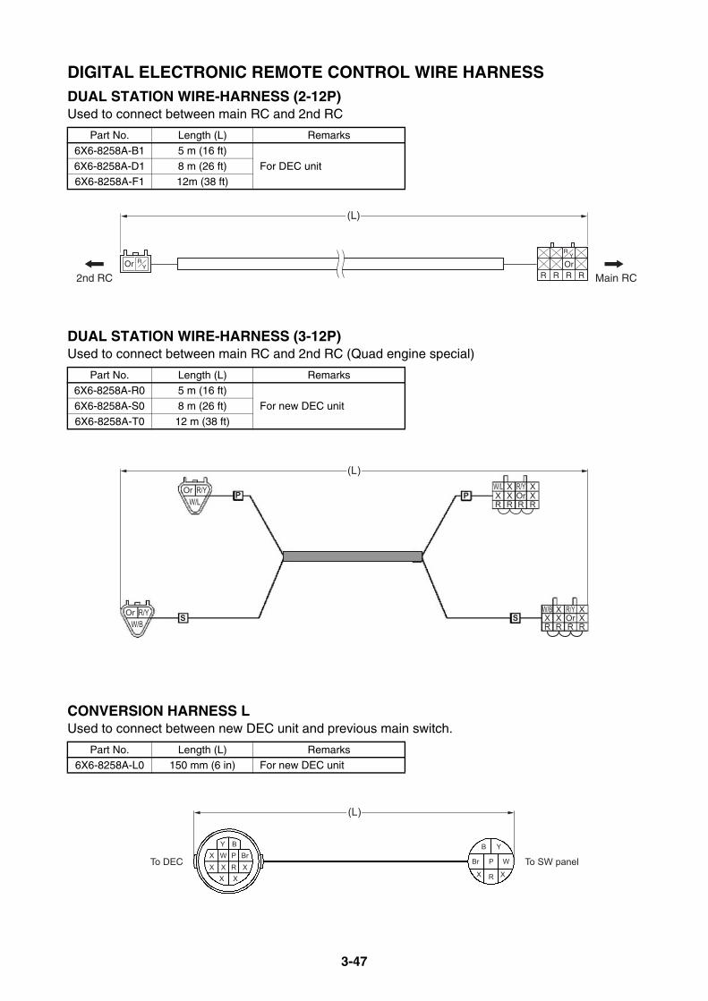
3-47
DIGITAL ELECTRONIC REMOTE CONTROL WIRE HARNESSDUAL STATION WIRE-HARNESS (2-12P)Used to connect between main RC and 2nd RC
DUAL STATION WIRE-HARNESS (3-12P)Used to connect between main RC and 2nd RC (Quad engine special)
CONVERSION HARNESS LUsed to connect between new DEC unit and previous main switch.
Part No. Length (L) Remarks
6X6-8258A-B1 5 m (16 ft)
For DEC unit6X6-8258A-D1 8 m (26 ft)6X6-8258A-F1 12m (38 ft)
Part No. Length (L) Remarks6X6-8258A-R0 5 m (16 ft)
For new DEC unit6X6-8258A-S0 8 m (26 ft)
6X6-8258A-T0 12 m (38 ft)
Part No. Length (L) Remarks6X6-8258A-L0 150 mm (6 in) For new DEC unit
ROrR
YOrR R R
R Y
2nd RC Main RC
(L)
W/L X R/Y XX X Or XR R R R
W/B X R/Y XX X Or XR R R R
OrW/L
R/Y
OrW/B
R/Y
PP
S S
(L)
Y B
X X
WX P BrXX R X
B Y
Br P W
X R X
To DEC To SW panel
(L)
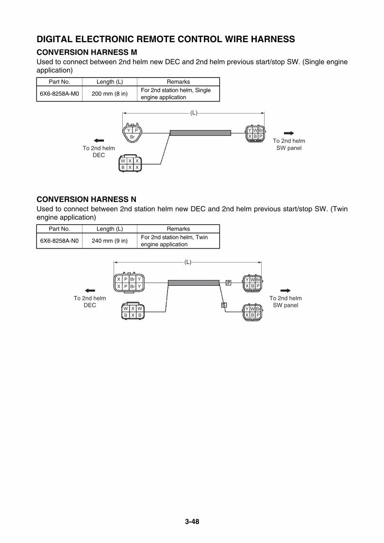
3-48
DIGITAL ELECTRONIC REMOTE CONTROL WIRE HARNESSCONVERSION HARNESS MUsed to connect between 2nd helm new DEC and 2nd helm previous start/stop SW. (Single engineapplication)
CONVERSION HARNESS NUsed to connect between 2nd station helm new DEC and 2nd helm previous start/stop SW. (Twinengine application)
Part No. Length (L) Remarks
6X6-8258A-M0 200 mm (8 in)For 2nd station helm, Single engine application
Part No. Length (L) Remarks
6X6-8258A-N0 240 mm (9 in)For 2nd station helm, Twin engine application
Y Y W BrX B P
W X XB X X
PBr
(L)
To 2nd helmDEC
To 2nd helmSW panel
X P Br
X P Br
Y
Y
Y W BrX B P
W X W
B X BY W BrX B P
(L)
P
STo 2nd helm
DECTo 2nd helm
SW panel

3-49
DIGITAL ELECTRONIC REMOTE CONTROL WIRE HARNESSCONVERSION HARNESS PUsed to connect between 2nd helm new DEC and 2nd helm previous start/stop SW. (Triple engineapplication)
Part No. Length (L) Remarks
6X6-8258A-P0 240 mm (9 in)For 2nd station helm, Triple engine application
X P Br
X P Br
Y
Y
X P Br Y
Y W BrX B P
Y W BrX B P
Y W BrX B P
W W W
B B B
(L)
P
S
C
To 2nd helmDEC
To 2nd helmSW panel

MEMO
4-1
TILLER HANDLES
6X4 MULTI-FUNCTION TILLER HANDLE............................................... 4-2MULTI-FUNCTION TILLER HANDLE KIT (FOR US)........................... 4-2
TILLER HANDLE KIT CONTENTS....................................................... 4-6
WIRING DIAGRAM (FOR US)............................................................ 4-11
EXPLODED DIAGRAM (FOR US) ..................................................... 4-12
MULTI-FUNCTION TILLER HANDLE KIT (FOR JAPAN) .................. 4-13
WIRING DIAGRAM (FOR JAPAN) ..................................................... 4-15
EXPLODED DIAGRAM (FOR JAPAN)............................................... 4-16
MULTI-FUNCTION TILLER HANDLE CONTENTS
(FOR OTHERS) ............................................................................. 4-17
TILLER HANDLE GROMMET DESCRIPTION................................... 4-17
MULTI-FUNCTION TILLER HANDLE KIT (FOR EU & ANZ) ............. 4-18
HANDLE IMMOBILIZER KIT CONTENTS ......................................... 4-22
WIRING DIAGRAM (FOR EU & ANZ) ................................................ 4-23
STEERING FRICTION CONTENTS ....................................................... 4-24
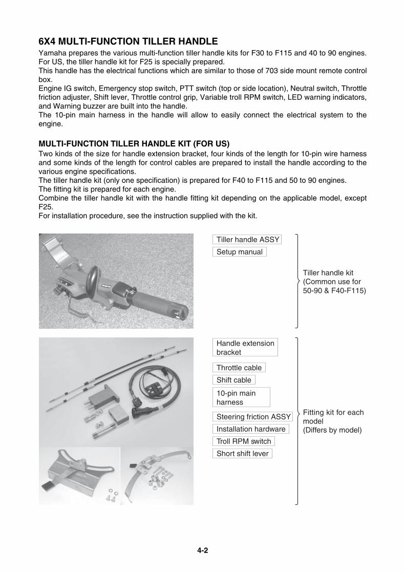
4-2
6X4 MULTI-FUNCTION TILLER HANDLEYamaha prepares the various multi-function tiller handle kits for F30 to F115 and 40 to 90 engines.For US, the tiller handle kit for F25 is specially prepared.This handle has the electrical functions which are similar to those of 703 side mount remote controlbox.Engine IG switch, Emergency stop switch, PTT switch (top or side location), Neutral switch, Throttlefriction adjuster, Shift lever, Throttle control grip, Variable troll RPM switch, LED warning indicators,and Warning buzzer are built into the handle.The 10-pin main harness in the handle will allow to easily connect the electrical system to theengine.
MULTI-FUNCTION TILLER HANDLE KIT (FOR US)Two kinds of the size for handle extension bracket, four kinds of the length for 10-pin wire harnessand some kinds of the length for control cables are prepared to install the handle according to thevarious engine specifications.The tiller handle kit (only one specification) is prepared for F40 to F115 and 50 to 90 engines.The fitting kit is prepared for each engine.Combine the tiller handle kit with the handle fitting kit depending on the applicable model, exceptF25.For installation procedure, see the instruction supplied with the kit.
Tiller handle ASSY
Setup manual
Fitting kit for eachmodel(Differs by model)
Tiller handle kit(Common use for 50-90 & F40-F115)
Handle extensionbracket
Throttle cable
Shift cable
10-pin main harness
Steering friction ASSY
Installation hardware
Troll RPM switch
Short shift lever
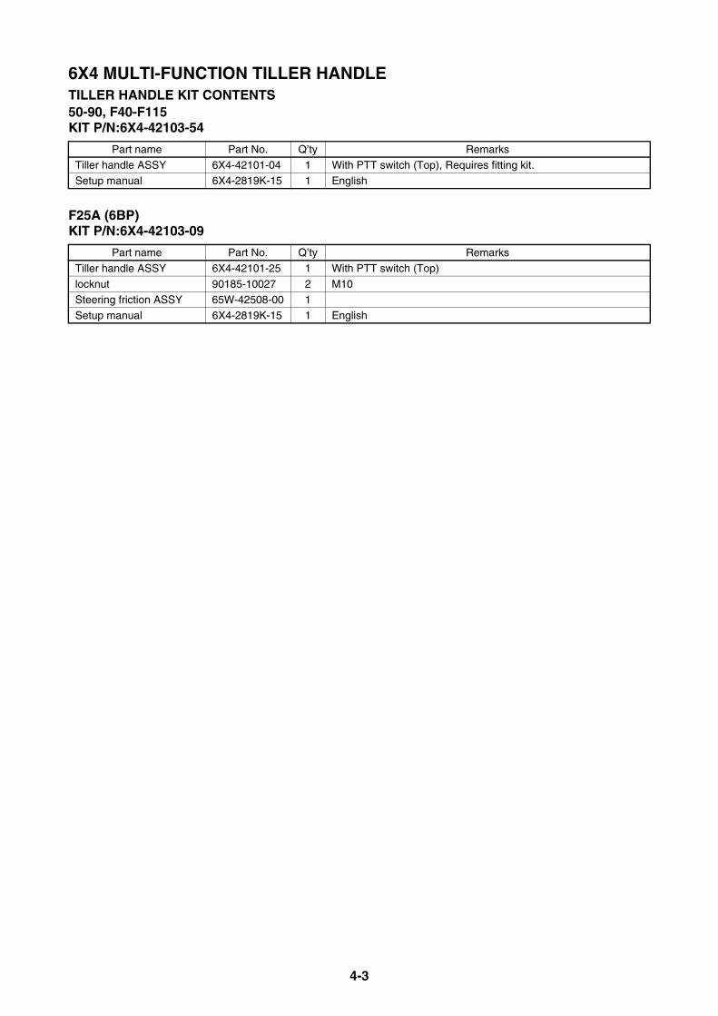
4-3
6X4 MULTI-FUNCTION TILLER HANDLETILLER HANDLE KIT CONTENTS50-90, F40-F115KIT P/N:6X4-42103-54
F25A (6BP)KIT P/N:6X4-42103-09
Part name Part No. Q’ty Remarks
Tiller handle ASSY 6X4-42101-04 1 With PTT switch (Top), Requires fitting kit.Setup manual 6X4-2819K-15 1 English
Part name Part No. Q’ty Remarks
Tiller handle ASSY 6X4-42101-25 1 With PTT switch (Top)
locknut 90185-10027 2 M10Steering friction ASSY 65W-42508-00 1
Setup manual 6X4-2819K-15 1 English
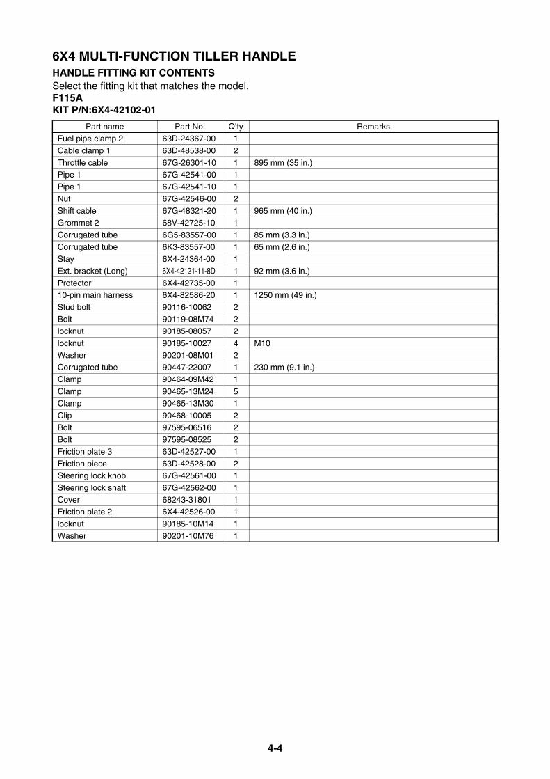
4-4
6X4 MULTI-FUNCTION TILLER HANDLEHANDLE FITTING KIT CONTENTSSelect the fitting kit that matches the model.F115AKIT P/N:6X4-42102-01
Part name Part No. Q’ty RemarksFuel pipe clamp 2 63D-24367-00 1
Cable clamp 1 63D-48538-00 2
Throttle cable 67G-26301-10 1 895 mm (35 in.)Pipe 1 67G-42541-00 1
Pipe 1 67G-42541-10 1
Nut 67G-42546-00 2Shift cable 67G-48321-20 1 965 mm (40 in.)
Grommet 2 68V-42725-10 1
Corrugated tube 6G5-83557-00 1 85 mm (3.3 in.)
Corrugated tube 6K3-83557-00 1 65 mm (2.6 in.)Stay 6X4-24364-00 1
Ext. bracket (Long) 6X4-42121-11-8D 1 92 mm (3.6 in.)
Protector 6X4-42735-00 110-pin main harness 6X4-82586-20 1 1250 mm (49 in.)
Stud bolt 90116-10062 2
Bolt 90119-08M74 2locknut 90185-08057 2
locknut 90185-10027 4 M10
Washer 90201-08M01 2Corrugated tube 90447-22007 1 230 mm (9.1 in.)
Clamp 90464-09M42 1
Clamp 90465-13M24 5Clamp 90465-13M30 1
Clip 90468-10005 2
Bolt 97595-06516 2Bolt 97595-08525 2
Friction plate 3 63D-42527-00 1
Friction piece 63D-42528-00 2Steering lock knob 67G-42561-00 1
Steering lock shaft 67G-42562-00 1
Cover 68243-31801 1Friction plate 2 6X4-42526-00 1
locknut 90185-10M14 1
Washer 90201-10M76 1

4-5
6X4 MULTI-FUNCTION TILLER HANDLEHANDLE FITTING KIT CONTENTSF115BKIT P/N: 6X4-42102-C0
Part name Part No. Q’ty Remarks
STR friction assy 67G-42508-10 1Stud bolt 90116-10063 2
Locknut 90185-10027 2 M10
Bracket 6EK-42121-00 1Shift cable 6EK-48321-00 1 820 mm (33.5 in)
Clip 90468-10005 2
Cable clamp 63D-48538-00 2Throttle cable 6EK-26301-00 1 710 mm (29.1 in)
Clamp 90464-09M42 1
10-pin main harness 6X4-82586-10 1 950 mm (37.4 in)
Clamp 90465-13M24 1Troll RPM switch assy 6X4-81860-00 1

4-6
6X4 MULTI-FUNCTION TILLER HANDLETILLER HANDLE KIT CONTENTSF75A, F90AKIT P/N:6X4-42102-11
Part name Part No. Q’ty Remarks
Fuel pipe clamp 2 63D-24367-00 1Cable clamp 1 63D-48538-00 2
Throttle cable 67G-26301-10 1 895 mm (35 in.)
Pipe 1 67G-42541-00 1Pipe 1 67G-42541-10 1
Nut 67G-42546-00 2
Shift cable 67G-48321-20 1 965 mm (40 in.)
Grommet 2 68V-42725-10 1Corrugated tube 6G5-83557-00 1 85 mm (3.3 in.)
Corrugated tube 6K3-83557-00 1 65 mm (2.6 in.)
Stay 6X4-24364-00 1Ext. bracket (Short) 6X4-42121-00-8D 1 45 mm (1.8 in.)
Protector 6X4-42735-00 1
Troll RPM switch ASSY 6X4-81860-00 110-pin main harness 6X4-82586-20 1 1250 mm (49 in.)
Stud bolt 90116-10031 2 M10-70 mm
Bolt 90119-08M74 2locknut 90185-08057 2
locknut 90185-10027 2 M10
Washer 90201-08M01 2Corrugated tube 90447-22007 1 230 mm (9.1 in.)
Clamp 90464-09M42 1
Clamp 90465-13M24 5Clamp 90465-13M30 1
Clip 90468-10005 2
Bolt 97595-06516 2Bolt 97595-08525 2
Friction plate 3 63D-42527-00 1
Friction piece 63D-42528-00 2Steering lock knob 67G-42561-00 1
Steering lock shaft 67G-42562-00 1
Cover 68243-31801 1Friction plate 2 6X4-42526-00 1
locknut 90185-10M14 1
Washer 90201-10M76 1
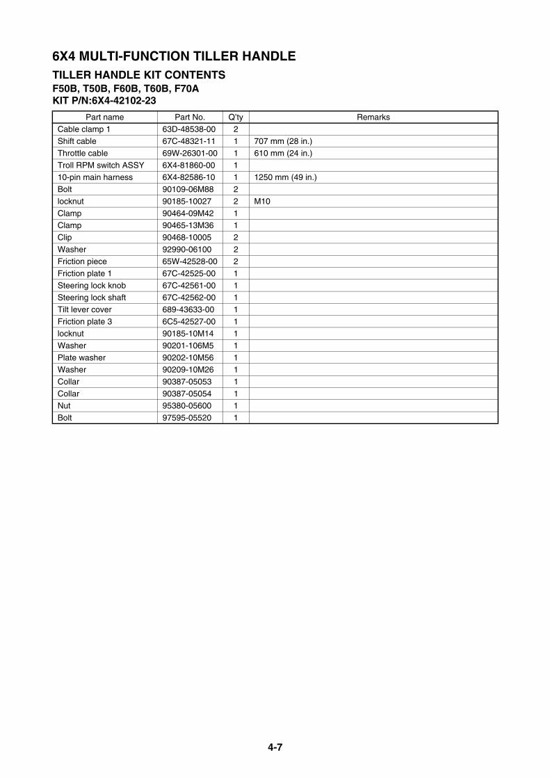
4-7
6X4 MULTI-FUNCTION TILLER HANDLETILLER HANDLE KIT CONTENTSF50B, T50B, F60B, T60B, F70AKIT P/N:6X4-42102-23
Part name Part No. Q’ty Remarks
Cable clamp 1 63D-48538-00 2Shift cable 67C-48321-11 1 707 mm (28 in.)
Throttle cable 69W-26301-00 1 610 mm (24 in.)
Troll RPM switch ASSY 6X4-81860-00 110-pin main harness 6X4-82586-10 1 1250 mm (49 in.)
Bolt 90109-06M88 2
locknut 90185-10027 2 M10
Clamp 90464-09M42 1Clamp 90465-13M36 1
Clip 90468-10005 2
Washer 92990-06100 2Friction piece 65W-42528-00 2
Friction plate 1 67C-42525-00 1
Steering lock knob 67C-42561-00 1Steering lock shaft 67C-42562-00 1
Tilt lever cover 689-43633-00 1
Friction plate 3 6C5-42527-00 1locknut 90185-10M14 1
Washer 90201-106M5 1
Plate washer 90202-10M56 1Washer 90209-10M26 1
Collar 90387-05053 1
Collar 90387-05054 1Nut 95380-05600 1
Bolt 97595-05520 1

4-8
6X4 MULTI-FUNCTION TILLER HANDLETILLER HANDLE KIT CONTENTSF40AKIT P/N:6X4-42102-71
Part name Part No. Q’ty Remarks
Cable clamp 1 63D-48538-00 2Shift cable 67C-48321-11 1 687 mm (27 in.)
Throttle cable 69W-26301-00 1 610 mm (24 in.)
Troll RPM switch ASSY 6X4-81860-00 110-pin main harness 6X4-82586-10 1 950 mm (37 in.)
Bolt 90109-06M88 2
locknut 90185-10027 2 M10
Clamp 90464-09M42 1Clamp 90465-13M36 1
Clip 90468-10005 2
Washer 92990-06100 2Friction piece 65W-42528-00 2
Friction plate 1 67C-42525-00 1
Friction plate 3 67C-42527-03 1Steering lock knob 67C-42561-00 1
Steering lock shaft 67C-42562-00 1
Tilt lever cover 68943-63300 1locknut 90185-10M14 1
Washer 90201-106M5 1
Plate washer 90202-10M56 1Washer 90209-10M26 1
Collar 90387-05053 1
Collar 90387-05054 1Nut 95380-05600 1
Bolt 97595-05520 1
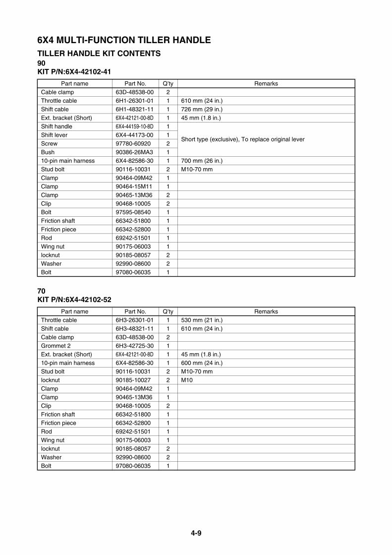
4-9
6X4 MULTI-FUNCTION TILLER HANDLETILLER HANDLE KIT CONTENTS90KIT P/N:6X4-42102-41
70KIT P/N:6X4-42102-52
Part name Part No. Q’ty Remarks
Cable clamp 63D-48538-00 2Throttle cable 6H1-26301-01 1 610 mm (24 in.)
Shift cable 6H1-48321-11 1 726 mm (29 in.)
Ext. bracket (Short) 6X4-42121-00-8D 1 45 mm (1.8 in.)Shift handle 6X4-44159-10-8D 1
Short type (exclusive), To replace original leverShift lever 6X4-44173-00 1
Screw 97780-60920 2
Bush 90386-26MA3 110-pin main harness 6X4-82586-30 1 700 mm (26 in.)
Stud bolt 90116-10031 2 M10-70 mm
Clamp 90464-09M42 1Clamp 90464-15M11 1
Clamp 90465-13M36 2
Clip 90468-10005 2Bolt 97595-08540 1
Friction shaft 66342-51800 1
Friction piece 66342-52800 1Rod 69242-51501 1
Wing nut 90175-06003 1
locknut 90185-08057 2Washer 92990-08600 2
Bolt 97080-06035 1
Part name Part No. Q’ty RemarksThrottle cable 6H3-26301-01 1 530 mm (21 in.)
Shift cable 6H3-48321-11 1 610 mm (24 in.)
Cable clamp 63D-48538-00 2Grommet 2 6H3-42725-30 1
Ext. bracket (Short) 6X4-42121-00-8D 1 45 mm (1.8 in.)
10-pin main harness 6X4-82586-30 1 600 mm (24 in.)Stud bolt 90116-10031 2 M10-70 mm
locknut 90185-10027 2 M10
Clamp 90464-09M42 1Clamp 90465-13M36 1
Clip 90468-10005 2
Friction shaft 66342-51800 1Friction piece 66342-52800 1
Rod 69242-51501 1
Wing nut 90175-06003 1locknut 90185-08057 2
Washer 92990-08600 2
Bolt 97080-06035 1
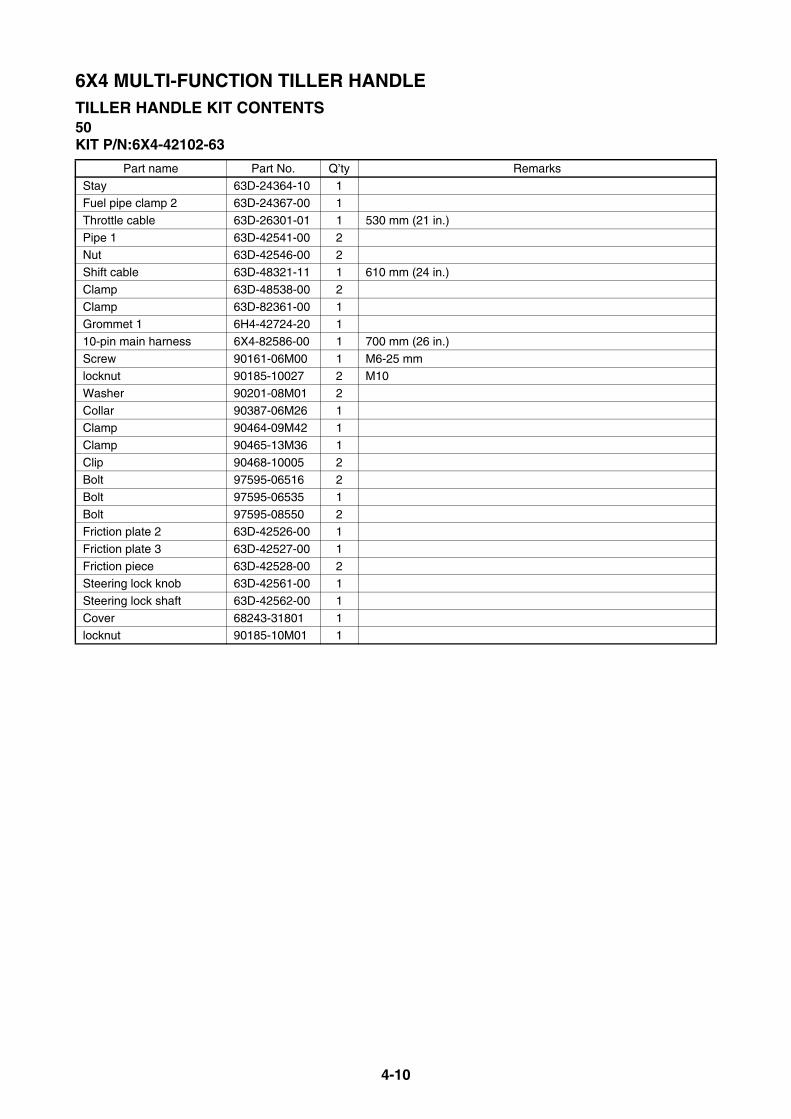
4-10
6X4 MULTI-FUNCTION TILLER HANDLETILLER HANDLE KIT CONTENTS50KIT P/N:6X4-42102-63
Part name Part No. Q’ty Remarks
Stay 63D-24364-10 1Fuel pipe clamp 2 63D-24367-00 1
Throttle cable 63D-26301-01 1 530 mm (21 in.)
Pipe 1 63D-42541-00 2Nut 63D-42546-00 2
Shift cable 63D-48321-11 1 610 mm (24 in.)
Clamp 63D-48538-00 2
Clamp 63D-82361-00 1Grommet 1 6H4-42724-20 1
10-pin main harness 6X4-82586-00 1 700 mm (26 in.)
Screw 90161-06M00 1 M6-25 mmlocknut 90185-10027 2 M10
Washer 90201-08M01 2
Collar 90387-06M26 1Clamp 90464-09M42 1
Clamp 90465-13M36 1
Clip 90468-10005 2Bolt 97595-06516 2
Bolt 97595-06535 1
Bolt 97595-08550 2Friction plate 2 63D-42526-00 1
Friction plate 3 63D-42527-00 1
Friction piece 63D-42528-00 2Steering lock knob 63D-42561-00 1
Steering lock shaft 63D-42562-00 1
Cover 68243-31801 1locknut 90185-10M01 1
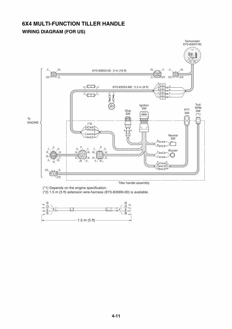
4-11
6X4 MULTI-FUNCTION TILLER HANDLEWIRING DIAGRAM (FOR US)
1
2
3
4
5
TACH
x100r/min
set mode
h
1.5 m (5 ft)
Y L
Y L
6Y5-83653-00 : 5 m (16 ft)
6Y5-83553-M0 : 2.5 m (8 ft)
IgnitionSW
Tachometer6Y5-8350T-90
NeutralSW
PTTSW
TrollRPMSW(*1)
Buzzer
StopSW
(*1) Depends on the engine specification.(*2) 1.5 m (5 ft) extension wire-harness (6Y5-8356N-00) is available.
(*2)
R
SbLg
P
Y
R
SbLg
G
B
Y
L
R
Y
R
Y
BR
Y
G
Br
Br
W B
BRRYYG
R
G
B
Y
L
GR
Lg
PBr
B
Sb
W
Y
Gy
G
P
G/R
Gy
G/W
P
G/R
P
G/R
Gy
G
BW/L
O/W
ToENGINE
X
Y
Br P
W
Lg
B
GR
Sb
Y
BrP
W
Lg
B
GR
Sb
Tiller handle assembly
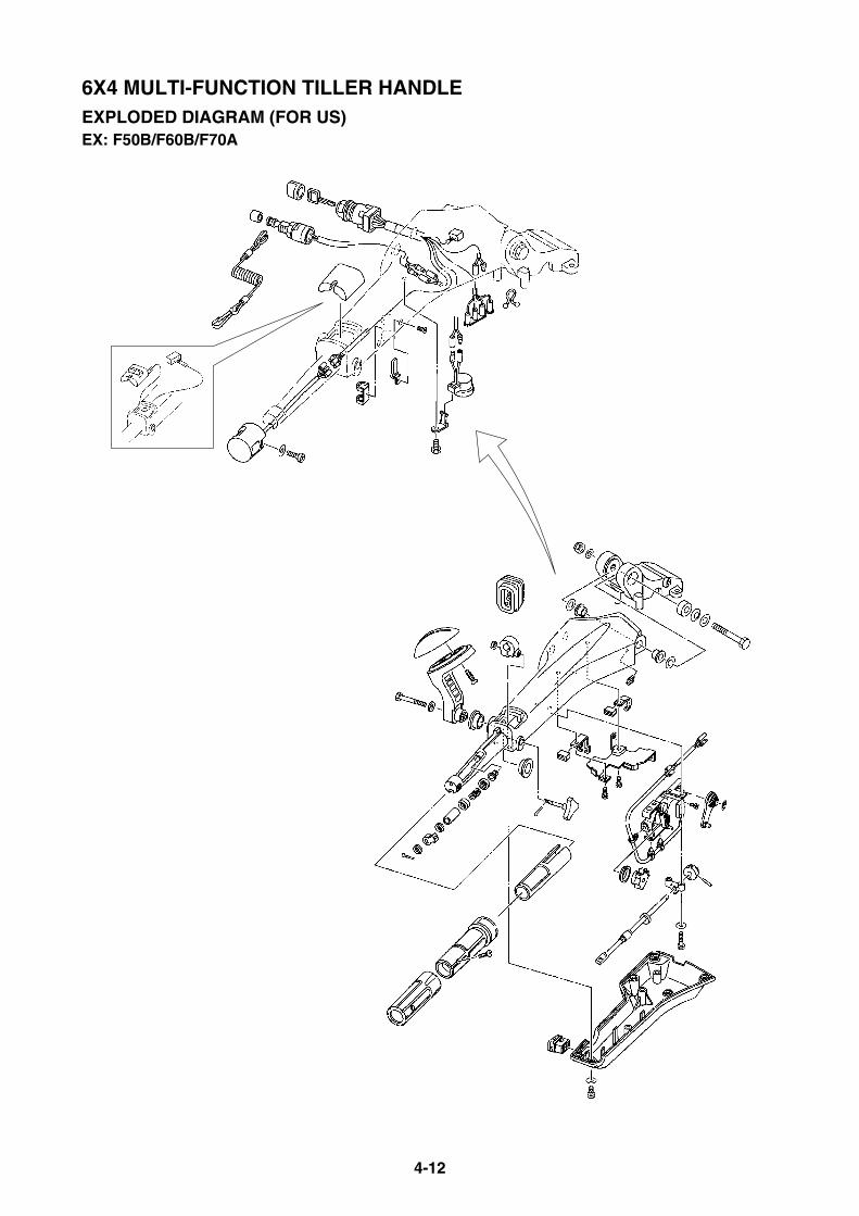
4-12
6X4 MULTI-FUNCTION TILLER HANDLEEXPLODED DIAGRAM (FOR US)EX: F50B/F60B/F70A

4-13
6X4 MULTI-FUNCTION TILLER HANDLEMULTI-FUNCTION TILLER HANDLE KIT (FOR JAPAN)The tiller handle kit is prepared for F50 to F90.For installation procedure, see the instruction supplied with the kit.
TILLER HANDLE KIT CONTENTSF80B, F90BKIT P/N:6X4-42103-16
Part name Part No. Q’ty RemarksFuel pipe clamp 2 63D-24367-00 1
Pipe 1 67G-42541-00 2
Nut 67G-42546-00 2Grommet 2 68V-42725-10 1
Corrugated tube 6G5-83557-00 1 85 mm (3.3 in.)
Corrugated tube 6K3-83557-00 1 65 mm (2.6 in.)Stay 6X4-24364-00 1
Tiller handle ASSY 6X4-42101-34 1 With PTT switch (Side), LED indicators
Ext. bracket (Short) 6X4-42121-00-8D 1 45 mm (1.8 in.)Protector 6X4-42735-00 1
Stud bolt 90116-10031 2
Bolt 90119-08M74 2locknut 90185-08057 2
locknut 90185-10027 2 M10
Washer 90201-08M01 2Corrugated tube 90447-22007 1 230 mm (9.1 in.)
Clamp 90465-13M24 5
Clamp 90465-13M30 1Bolt 97595-06516 2
Bolt 97595-08525 2
Friction plate 3 63D-42527-00 1
Friction piece 63D-42528-00 2Steering lock knob 67G-42561-00 1
Steering lock shaft 67G-42562-00 1
Cover 68243-31801 1Friction plate 2 6X4-42526-00 1
locknut 90185-10M14 1
Washer 90201-10M76 1Setup manual 6X4-2819K-04 1 Japanese
Troll RPM switch(Fuel injected F30- F90)Troll RPM switch(Fuel injected F30- F90)
PTT switch (Side)
LED indicators* Overheat warning* Oil warning
PTT switch (Side)
LED indicators* Overheat warning* Oil warning

4-14
6X4 MULTI-FUNCTION TILLER HANDLETILLER HANDLE KIT CONTENTSF50H, FT50J, F60F, FT60G, F70AKIT P/N:6X4-42103-27
FT50C,F50DKIT P/N:6X4-42103-47
Part name Part No. Q’ty Remarks
Grommet 2 6C5-42725-30 1Tiller handle ASSY 6X4-42101-V5 1 With PTT switch (Side), LED indicators
Bolt 901-0906M-88 2 M10
locknut 90185-10027 2Clamp 90465-13M36 1
Washer 92990-06100 2
Friction piece 65W-42528-00 2
Friction plate 1 67C-42525-00 1Steering lock knob 67C-42561-00 1
Steering lock shaft 67C-42562-00 1
Tilt lever cover 689-43633-00 1Friction plate 3 6C5-42527-00 1
locknut 90185-10M14 1
Washer 90201-106M5 1Plate washer 90202-10M56 1
Washer 90209-10M26 1
Collar 90387-05053 1Collar 90387-05054 1
Nut 95380-05600 1
Bolt 97595-05520 1Setup manual 6X4-2819K-04 1 Japanese
Part name Part No. Q’ty Remarks
Grommet 2 62Y-42725-30 1Tiller handle ASSY 6X4-42101-45 1 With PTT switch (Side), LED indicators
locknut 90185-10027 2 M10
Clamp 90465-13M36 1Setup manual 6X4-2819K-04 1 Japanese
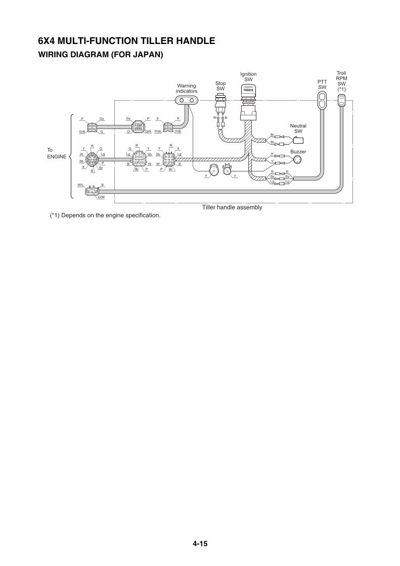
4-15
6X4 MULTI-FUNCTION TILLER HANDLEWIRING DIAGRAM (FOR JAPAN)
IgnitionSW
NeutralSW
PTTSW
TrollRPMSW(*1)
Buzzer
StopSW
ToENGINE
RSbLg
P
Y
RSbLg
Br
Br
W B
Y
Br PW
Lg
B
GR
Sb
Y
BrPW
Lg
B
XR
Sb
GR
Lg
PBr
BX
Sb
W
Y
Gy
G
P
G/R
X
P/B
X
P/W
P
G/R
Gy
G
BW/L
O/W
Warningindicators
YY
(*1) Depends on the engine specification.Tiller handle assembly
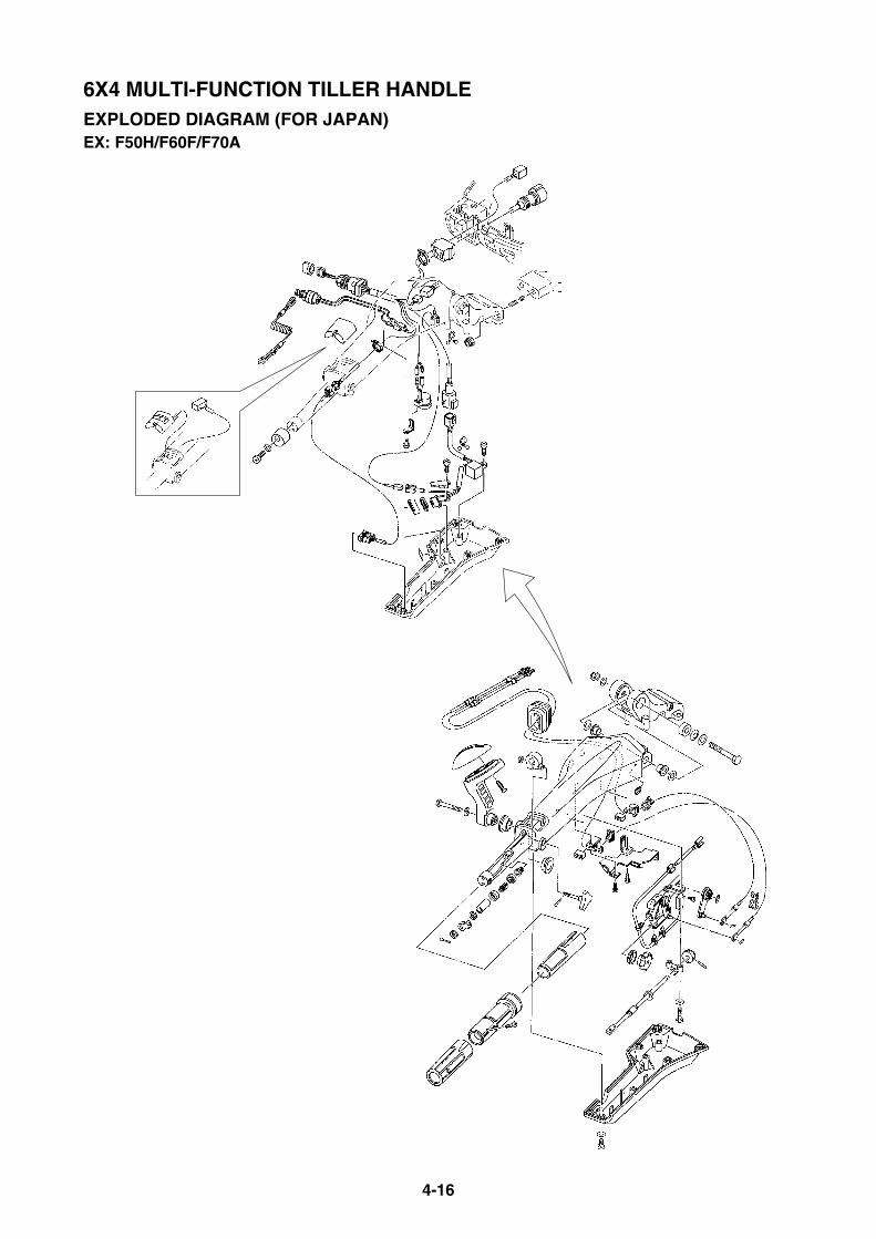
4-16
6X4 MULTI-FUNCTION TILLER HANDLEEXPLODED DIAGRAM (FOR JAPAN)EX: F50H/F60F/F70A
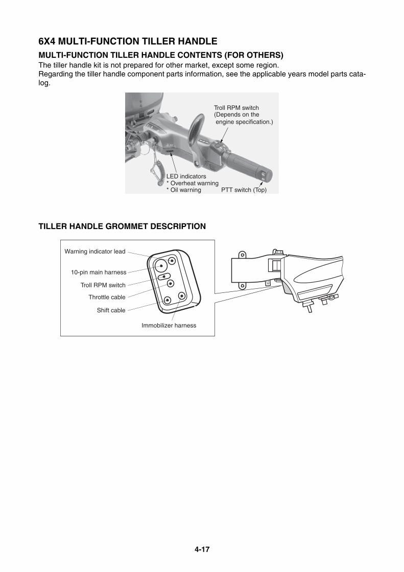
4-17
6X4 MULTI-FUNCTION TILLER HANDLEMULTI-FUNCTION TILLER HANDLE CONTENTS (FOR OTHERS)The tiller handle kit is not prepared for other market, except some region.Regarding the tiller handle component parts information, see the applicable years model parts cata-log.
TILLER HANDLE GROMMET DESCRIPTION
Troll RPM switch(Depends on the engine specification.)
LED indicators* Overheat warning* Oil warning PTT switch (Top)
Warning indicator lead
10-pin main harness
Troll RPM switch
Throttle cable
Shift cable
Immobilizer harness
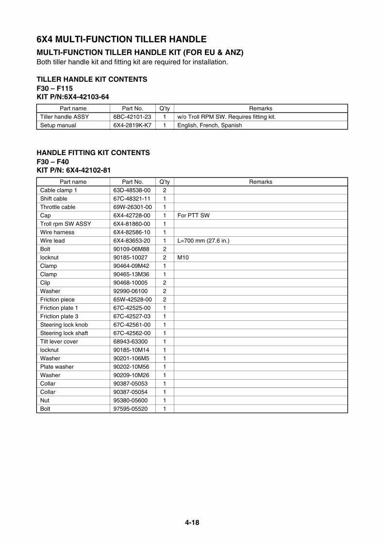
4-18
6X4 MULTI-FUNCTION TILLER HANDLEMULTI-FUNCTION TILLER HANDLE KIT (FOR EU & ANZ)Both tiller handle kit and fitting kit are required for installation.
TILLER HANDLE KIT CONTENTSF30 – F115KIT P/N:6X4-42103-64
HANDLE FITTING KIT CONTENTSF30 – F40KIT P/N: 6X4-42102-81
Part name Part No. Q’ty Remarks
Tiller handle ASSY 6BC-42101-23 1 w/o Troll RPM SW. Requires fitting kit.
Setup manual 6X4-2819K-K7 1 English, French, Spanish
Part name Part No. Q’ty Remarks
Cable clamp 1 63D-48538-00 2
Shift cable 67C-48321-11 1Throttle cable 69W-26301-00 1
Cap 6X4-42728-00 1 For PTT SW
Troll rpm SW ASSY 6X4-81860-00 1Wire harness 6X4-82586-10 1
Wire lead 6X4-83653-20 1 L=700 mm (27.6 in.)
Bolt 90109-06M88 2locknut 90185-10027 2 M10
Clamp 90464-09M42 1
Clamp 90465-13M36 1Clip 90468-10005 2
Washer 92990-06100 2
Friction piece 65W-42528-00 2Friction plate 1 67C-42525-00 1
Friction plate 3 67C-42527-03 1
Steering lock knob 67C-42561-00 1Steering lock shaft 67C-42562-00 1
Tilt lever cover 68943-63300 1
locknut 90185-10M14 1Washer 90201-106M5 1
Plate washer 90202-10M56 1
Washer 90209-10M26 1Collar 90387-05053 1
Collar 90387-05054 1
Nut 95380-05600 1Bolt 97595-05520 1

4-19
6X4 MULTI-FUNCTION TILLER HANDLEMULTI-FUNCTION TILLER HANDLE KIT (FOR EU & ANZ)F50 – F70KIT P/N: 6X4-42102-91
Part name Part No. Q’ty Remarks
Cable clamp 1 63D-48538-00 2Shift cable 67C-48321-11 1
Throttle cable 69W-26301-00 1
Cap 6X4-42728-00 1 For PTT SWTroll rpm SW ASSY 6X4-81860-00 1
Wire harness 6X4-82586-10 1
Wire lead 6X4-83653-20 1 L=700 mm (27.6 in.)
Bolt 90109-06M88 2locknut 90185-10027 2 M10
Clamp 90464-09M42 1
Clamp 90465-13M36 1Clip 90468-10005 2
Washer 92990-06100 2
Friction piece 65W-42528-00 2Friction plate 1 67C-42525-00 1
Steering lock knob 67C-42561-00 1
Steering lock shaft 67C-42562-00 1Tilt lever cover 689-43633-00 1
Friction plate 3 6C5-42527-00 1
locknut 90185-10M14 1Washer 90201-106M5 1
Plate washer 90202-10M56 1
Washer 90209-10M26 1Collar 90387-05053 1
Collar 90387-05054 1
Nut 95380-05600 1Bolt 97595-05520 1

4-20
6X4 MULTI-FUNCTION TILLER HANDLEMULTI-FUNCTION TILLER HANDLE KIT (FOR EU & ANZ)HANDLE FITTING KIT CONTENTSF80 – F100KIT P/N: 6X4-42102-A1
Part name Part No. Q’ty Remarks
Fuel pipe clamp 2 63D-24367-00 1Cable clamp 1 63D-48538-00 2
Throttle cable 67G-26301-10 1
Pipe 1 67G-42541-00 1Pipe 1 67G-42541-10 1
NUT 67G-42546-00 2
Shift cable 67G-48321-20 1
Grommet 2 68V-42725-10 1Corrugated tube 6G5-83557-00 1 85 mm (3.3 in.)
Corrugated tube 6K3-83557-00 1 65 mm (2.6 in.)
Stay 6X4-24364-00 1Bracket 6X4-42121-00-8D 1 45 mm (short)
Protector 6X4-42735-00 1
Troll rpm SW ASSY 6X4-81860-00 1Wire harness 6X4-82586-20 1 1250 mm (49.2 in.)
Wire lead 6X4-83653-00 1 L=1250 mm (49.2 in.)
Stud bolt 90116-10031 2Bolt 90119-08M74 2
locknut 90185-08057 2
locknut 90185-10027 2 M10Washer 90201-08M01 2
Corrugated tube 90447-22007 1 230 mm (9.1 in.)
Clamp 90464-09M42 1Clamp 90465-13M24 5
Clamp 90465-13M30 1
Clip 90468-10005 2Bolt 97595-06516 2
Bolt 97595-08525 2
Friction plate 3 63D-42527-00 1Friction piece 63D-42528-00 2
Steering lock knob 67G-42561-00 1
Steering lock shaft 67G-42562-00 1Cover 68243-31801 1
Friction plate 2 6X4-42526-00 1
locknut 90185-10M14 1Washer 90201-10M76 1
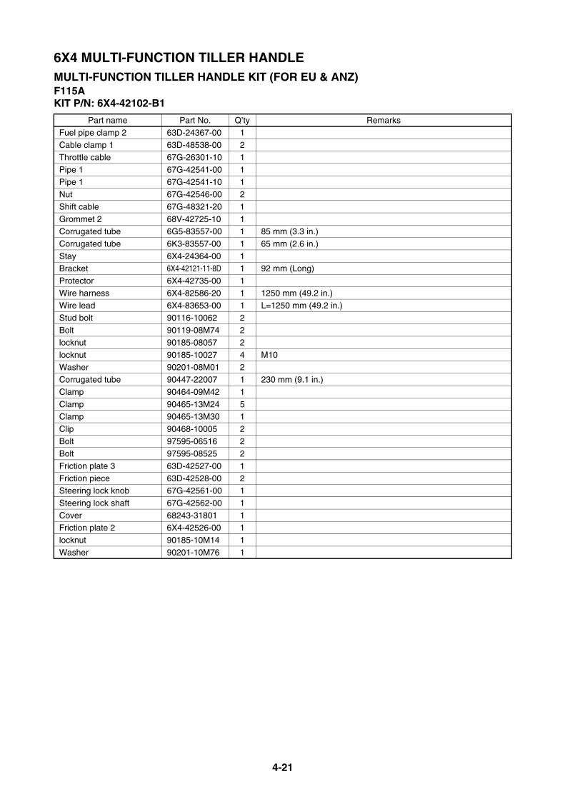
4-21
6X4 MULTI-FUNCTION TILLER HANDLEMULTI-FUNCTION TILLER HANDLE KIT (FOR EU & ANZ)F115AKIT P/N: 6X4-42102-B1
Part name Part No. Q’ty Remarks
Fuel pipe clamp 2 63D-24367-00 1Cable clamp 1 63D-48538-00 2
Throttle cable 67G-26301-10 1
Pipe 1 67G-42541-00 1Pipe 1 67G-42541-10 1
Nut 67G-42546-00 2
Shift cable 67G-48321-20 1
Grommet 2 68V-42725-10 1Corrugated tube 6G5-83557-00 1 85 mm (3.3 in.)
Corrugated tube 6K3-83557-00 1 65 mm (2.6 in.)
Stay 6X4-24364-00 1Bracket 6X4-42121-11-8D 1 92 mm (Long)
Protector 6X4-42735-00 1
Wire harness 6X4-82586-20 1 1250 mm (49.2 in.)Wire lead 6X4-83653-00 1 L=1250 mm (49.2 in.)
Stud bolt 90116-10062 2
Bolt 90119-08M74 2locknut 90185-08057 2
locknut 90185-10027 4 M10
Washer 90201-08M01 2Corrugated tube 90447-22007 1 230 mm (9.1 in.)
Clamp 90464-09M42 1
Clamp 90465-13M24 5Clamp 90465-13M30 1
Clip 90468-10005 2
Bolt 97595-06516 2Bolt 97595-08525 2
Friction plate 3 63D-42527-00 1
Friction piece 63D-42528-00 2Steering lock knob 67G-42561-00 1
Steering lock shaft 67G-42562-00 1
Cover 68243-31801 1Friction plate 2 6X4-42526-00 1
locknut 90185-10M14 1
Washer 90201-10M76 1

4-22
6X4 MULTI-FUNCTION TILLER HANDLEMULTI-FUNCTION TILLER HANDLE KIT (FOR EU & ANZ)F115BKIT P/N: 6X4-42102-C0
HANDLE IMMOBILIZER KIT CONTENTSF30B – F115BKIT P/N: 6Y8-W0035-C0
* Requires to replace the rigging grommet as follows.F50 up to F60: 6C5-42725-50F75 up to F115 (68V): 68V-42725-20
Part name Part No. Q’ty Remarks
STR friction assy 67G-42508-10 1Stud bolt 90116-10063 2
Locknut 90185-10027 2 M10
Bracket 6EK-42121-00 1Shift cable 6EK-48321-00 1 820 mm (33.5 in)
Clip 90468-10005 2
Cable clamp 63D-48538-00 2
Throttle cable 6EK-26301-00 1 710 mm (29.1 in)Clamp 90464-09M42 1
10-pin main harness 6X4-82586-10 1 950 mm (37.4 in)
Clamp 90465-13M24 1Troll RPM switch assy 6X4-81860-00 1
Part name Part No. Q’ty RemarksWire-harness 6Y5-83553-M0 1 2.5 m (8 ft)
Single hub 6Y8-81920-11 2
Wire-lead 6Y8-82117-00 1 For system PWRPigtail bus wire 6Y8-82521-51 1 3.6 m (12 ft)
Main bus wire 6Y8-82553-01 1 0.3 m (1 ft)
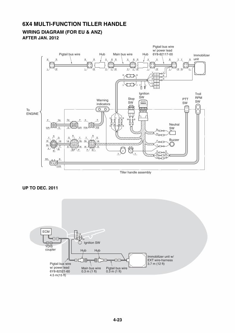
4-23
6X4 MULTI-FUNCTION TILLER HANDLEWIRING DIAGRAM (FOR EU & ANZ)AFTER JAN. 2012
UP TO DEC. 2011
R
SbLg
P
Y
R
SbLg
Br
Br
W B
Y
BrP
W
Lg
B
GR
Sb
Y
BrP
W
Lg
B
GR
Sb
GR
Lg
PBr
BX
Sb
W
Y
Gy
G
P
G/R
X
P/B
X
P/W
P
G/R
Gy
G
BW/L
O/W
YY
L W L W
B R B Y
L W
B R
L W
Y
B
R
Y
B
R
L
G
BRRYYG
BRYG
R R
Y Y Y L
LW
BY
Immobilizerunit
IgnitionSWStop
SWWarningindicators
PTTSW
TrollRPMSW
ToENGINE
Tiller handle assembly
NeutralSW
Buzzer
P
X B
X L
R
W
X B
X L
R
W
Pigtail bus wire Main bus wire
Pigtail bus wirew/ power lead6Y8-82117-00Hub Hub
X X
Pigtail bus wire0.3 m (1 ft)
Main bus wire0.3 m (1 ft)
Hub
Immobilizer unit w/EXT wire-harness3.7 m (12 ft)
YDIScoupler
R Sb
Lg
Ignition SW
ECM
Hub
Pigtail bus wirew/ power lead6Y8-82521-604.5 m(15 ft)
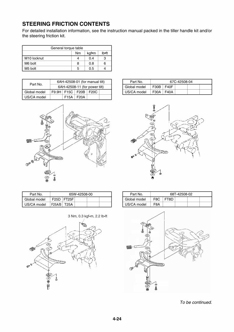
4-24
STEERING FRICTION CONTENTSFor detailed installation information, see the instruction manual packed in the tiller handle kit and/orthe steering friction kit.
To be continued.
General torque tableNm kgf•m lb•ft
M10 locknut 4 0.4 3
M6 bolt 8 0.8 6M5 bolt 5 0.5 4
Part No.6AH-42508-01 (for manual tilt)6AH-42508-11 (for power tilt)
Global model F9.9H F15C F20B F20C
US/CA model F15A F20A
Part No. 65W-42508-00Global model F25D FT25F
US/CA model F25A/B T25A
3 Nm, 0.3 kgf•m, 2.2 lb•ft
Part No. 67C-42508-04Global model F30B F40F
US/CA model F30A F40A
Part No. 68T-42508-02Global model F8C FT8D
US/CA model F8A

4-25
STEERING FRICTION CONTENTSPart No. 63D-42508-00
Global model 40V 50H FT50C F50D
US/CA model
Part No. 67G-42508-10
Global model F75B F80B F90B F100D F75CUS/CA model F75A F90A
Global model F95A F100B F/FL115A
US/CA model F/LF115AGlobal model F/FL115B
US/CA/ANZ model F/LF115B
18 Nm,1.8 kgf•m,13 lb•ft
20 Nm,2.0 kgf•m,
15 lb•ft
20 Nm,2.0 kgf•m,15 lb•ft
18 Nm,1.8 kgf•m,13 lb•ft
18 Nm,1.8 kgf•m,13 lb•ft
Use this hole for F115A,F100B, F95A, and F75C
Part No. 6C5-42508-01Global model F40H F50H FT50J F60F FT60G
US/CA model F50B T50B F60B T60B
Part No. 692-42508-01
Global model 60F 70B 75C 90AUS/CA model
Part No. 6E5-42508-01
Global model E115AUS/CA model
1/4 turns outfrom seatedposition

MEMO
5-1
CONVENTIONAL GAUGE (6Y5 & 6Y7)
MOUNTING THE METERS....................................................................... 5-4METER MOUNTING PROCEDURE..................................................... 5-4
ANALOG GAUGE ILLUMINATION (6Y7 TYPE) .................................. 5-4
ANALOG TACHOMETER ........................................................................ 5-5ANALOG TACHOMETER APPLICATIONS ......................................... 5-5
ANALOG TACHOMETER DIMENSIONS............................................. 5-6
POLE NUMBER SET UP...................................................................... 5-6
DIGITAL TACHOMETER.......................................................................... 5-7DIGITAL TACHOMETER APPLICATIONS .......................................... 5-7
DIGITAL TACHOMETER DIMENSIONS.............................................. 5-7
POLE NUMBER SET UP...................................................................... 5-8
SPEEDOMETER....................................................................................... 5-9SPEEDOMETER TYPES AND APPLICATIONS.................................. 5-9
SPEEDOMETER DIMENSIONS ........................................................ 5-10
WATER PRESSURE DAMPER (OP) ................................................. 5-10
SPEEDOMETER TUBE ROUTING.................................................... 5-11
DIGITAL SPEEDOMETER SET UP ................................................... 5-11
FUEL MANAGEMENT GAUGE.............................................................. 5-12FUEL MANAGEMENT GAUGE TYPES AND APPLICATIONS ......... 5-12
FUEL MANAGEMENT GAUGE DIMENSIONS.................................. 5-13
FUEL SENSOR INSTALLATION........................................................ 5-14
WIRING DESCRIPTION..................................................................... 5-15
FUEL MANAGEMENT GAUGE SET UP............................................ 5-17
FUEL MGT GAUGE WITH SPEEDOMETER SET UP....................... 5-17
ANALOG TRIM METER ......................................................................... 5-18ANALOG TRIM METER APPLICATIONS .......................................... 5-18
ANALOG TRIM METER DIMENSIONS.............................................. 5-18
TRIM SENSOR ADJUSTMENT.......................................................... 5-18
COOLANT PRESSURE METER ............................................................ 5-19COOLANT PRESSURE METER APPLICATIONS............................. 5-19
COOLANT PRESSURE METER DIMENSIONS ................................ 5-19
COOLANT PRESS. ATTACHMENT INSTALLATION........................ 5-19
To be continued.

5-2
CONVENTIONAL GAUGE (6Y5 & 6Y7)
COOLANT TEMP. METER ..................................................................... 5-20COOLANT TEMP. METER TYPES AND APPLICATIONS ................ 5-20
COOLANT TEMP. METER DIMENSIONS......................................... 5-20
COOLANT PRESS. ATTACHMENT AND/OR COOLANT TEMP.
SENSOR INSTALLATION (FOR 2-STROKE MODELS) ............... 5-21
ROUTING COOLANT TEMP. LEAD .................................................. 5-22
ROUTING THE COOLANT PRESS. TUBE........................................ 5-22
COOLANT TEMP. SENSOR AND/OR COOLANT PRESS.
ATTACHMENT INSTALLATION
(FOR 4-STROKE MODELS) .......................................................... 5-23
ROUTING THE COOLANT TEMP. LEAD &
COOLANT PRESS. TUBE............................................................. 5-25
SENSOR/ATTACHMENT INSTALLATION AND ROUTING .............. 5-26
HOUR METER ........................................................................................ 5-27HOUR METER APPLICATIONS ........................................................ 5-27
HOUR METER DIMENSIONS............................................................ 5-27
WIRING THE MECHANICAL HOUR METER .................................... 5-28
WIRING THE DIGITAL HOUR METER.............................................. 5-28
VOLTAGE METER ................................................................................. 5-29VOLTAGE METER TYPES AND APPLICATIONS............................. 5-29
VOLTAGE METER DIMENSIONS ..................................................... 5-29
WIRING THE VOLTAGE METER....................................................... 5-29
FUEL METER ......................................................................................... 5-30FUEL METER TYPES AND APPLICATIONS .................................... 5-30
FUEL METER DIMENSIONS ............................................................. 5-30
WIRING THE FUEL METER .............................................................. 5-30
CHARGE WARNING UNIT..................................................................... 5-31CHARGE WARNING UNIT TYPES AND APPLICATIONS................ 5-31
WIRING THE CHARGE WARNING UNIT .......................................... 5-31
To be continued.
5-3
CONVENTIONAL GAUGE (6Y5 & 6Y7)
WIRE HARNESSES................................................................................ 5-32REMOTE-OIL TANK HARNESS ........................................................ 5-32
ADDITIONAL ACCESSORY LEAD .................................................... 5-32
METER HARNESS............................................................................. 5-33
LAMP SWITCH................................................................................... 5-34
TRIM METER LEAD........................................................................... 5-34
TRIM AND OIL LEAD ......................................................................... 5-34
COMBINATION TRIM AND OIL LEAD............................................... 5-34
CONVERSION HARNESS 1 .............................................................. 5-35
FUEL MANAGEMENT GAUGE HARNESS ....................................... 5-35
LIGHTING COIL EXTENSION HARNESS ......................................... 5-35
RECTIFIER KIT .................................................................................. 5-35
WIRING DIAGRAMS .............................................................................. 5-36WIRE COLOR CODE ......................................................................... 5-36
DIGITAL METER (6Y5) ...................................................................... 5-37
ANALOG METER (6Y7) ..................................................................... 5-42
INTERCHANGEABILITY BETWEEN TACHOMETER AND ENGINE
(up to 2006 and after 2007)............................................................ 5-44
RIGGING GROMMET DESCRIPTION ................................................... 5-47

5-4
MOUNTING THE METERSThe meters can be installed to electrical start models because power source is required for theoperation.
METER MOUNTING PROCEDUREFollow the procedures below for mounting the gauges.1. Select a mounting location so that the meter is easy to read from the operating position.
Be sure that there is sufficient clearance behind the panel for the meter. For analog meters, be sure that the angle for mounting the meter is 65 to 90 degrees. If the analog gauge is mounted onto horizontal surface, the pointer may not return to the zero po-sition after the engine has stopped.
2. Make a hole at the desired position.3. Remove the fitting plate from the meter, fit the meter into the panel, and install the fitting plate
over the mounting studs.4. Place the washers over the studs, and then evenly tighten the mounting nuts until the meter can
no longer be rotated by hand.5. Connect the wire-harnesses to the gauges, and secure them into a boat.
* If the gauge is mounted onto a 13 mm (0.5 in) or thicker board, cut out the fitting plate end so that the mountnut is enough tightened.
ANALOG GAUGE ILLUMINATION (6Y7 TYPE)For black-face analog gauge, the faceplate is illuminated with permeation light for nighttime opera-tion.The white-face analog gauge used an indirect clear lighting.
65˚ – 90˚[Analog meter]
Gasket Fitting plate
Panelthickness
Cutting area(for thicker panel)
Nut
Wave washer
Mounting stud

5-5
ANALOG TACHOMETERA tachometer is essential for proper outboard performance.The engine speed can be monitored to obtain most efficient operation.In twin engine applications, the tachometers can be used to set the throttle of each engine accu-rately.
ANALOG TACHOMETER APPLICATIONS
* Tachometer with triple oil indicators (Ref. No.2) requires the relay to light the indicators. See the wiring diagram to connect the relay (P/N: 6Y5-81950-02).
* If the current tachometer does not fit the older engine, use the wire harness adapter which is shown in page5-44.
Ref. No. Description Part No. Applicable model
1
Without indicatorsBLK panel
6Y7-83540-20Pre-mixed 9.9 – 250FT8 (T8), F9.9 – F25 (FT/T25)Without indicators
WHT panel6Y7-83540-30
2
With 3 oil indicatorsBLK panel
6Y7-83540-00250G, L250G
With 3 oil indicatorsWHT panel
6Y7-83540-10
3
With overheat & oil indicatorsBLK panel
6Y7-83540-80 Above 40 (3-cyl) w/ oil injection (except 250G/L250G)Above F30 [Mechanical RC]With overheat & oil indicators
WHT panel6Y7-83540-90
1 2 3

5-6
ANALOG TACHOMETERANALOG TACHOMETER DIMENSIONS
POLE NUMBER SET UPYamaha tachometer shows the engine RPM by receiving the pulse signal from lighting coil.The flywheel magneto used on Yamaha outboard motors varies in number of poles used: 4-pole, 6-pole and 12-pole.It is necessary to adjust the calibration switch on the back of gauge to correspond to the particularmotor being used.The initial setting is 12-pole. Adjust if necessary.
(*1) Mechanical RC
POLE NUMBER ADJUSTMENT1. Remove the rubber grommet (1) from the back
of meter.2. Turn the rotating switch (2) with a slotted-head
screwdriver to the required position.3. Reinstall the grommet.
Description Applicable model4-pole 6 – 15, 55B, E/40G, E40J, E48C, E55C, EK40G, EK40J
6-pole20D, 25N, 30D, 40V, 50H, 60F70B, E/25B, EK25B, E/30H, E/40X, E60H, F8C (F8A), FT8D, F9.9J (F9.9B)
12-pole 55D, 75A, 75C, 85A, 90A, V4, V6, E75B, F15 (6AG) – F250 (*1)
93 (
3.66
)
11.2 (0.44) 65 (2.56)
28.9 (1.14)
200 (7.87)
200 (7.87)
84.5
(3.
33)
210
(8.2
7)
93 (
3.66
)
11.2 (0.44) 65 (2.56)
28.9 (1.14)
200 (7.87)
200 (7.87)
84.5
(3.
33)
210
(8.2
7)
R
P Br B
XR
Y B
G
P
Y
mm (in.)mm (in.)
3-indicator for 250G & L250G 2-indicator for 4-stroke and oil injected2-stroke engines (except 250G & L250G)

5-7
DIGITAL TACHOMETERA tachometer is essential for proper outboard performance.The engine speed can be monitored to obtain most efficient operation.In twin engine applications, the tachometers can be used to set the throttle of each engine accu-rately.The digital tachometer includes the elapsed hour meter, the trim meter and the oil warning indicator.Also, this meter can be used for both 2 and 4 stroke models by switching the settings.
DIGITAL TACHOMETER APPLICATIONS
(*1) Mechanical RC
* If the current tachometer does not fit the older engine, use the wire-harness adapter which is shown on page5-44.
DIGITAL TACHOMETER DIMENSIONS
Ref. No. Description Part No. Applicable model1 Multifunction 6Y5-8350T-04 250G,L250G
2Multifunction w/o “Check engine” and “Water in fuel” indicators
6Y5-8350T-91Above 40 (3-cyl) w/ oil injection & PTT (except 250G/L250G), Above F30 w/ PTT (*1)
1 2
1
2
3
4
5
TACH
x100r/min
set mode
h
1
2
3
4
5
TACH
x100r/min
set mode
h
97 (3
.82)
8.5 (0.33) 25 (0.98)
65.5 (2.58)210 (8.27)
190 (7.48)
84.5
(3.3
3)
97 (3
.82)
8.5 (0.33) 25 (0.98)
65.5 (2.58)
84.5
(3.3
3)
210
(8.2
7)
W RG R
L WG W
B WOr
Gy P
G R
G W
GyP
mm (in.)mm (in.)1. With twin 4-pin couplers (No.1) 2. With single 4-pin coupler (No.2)
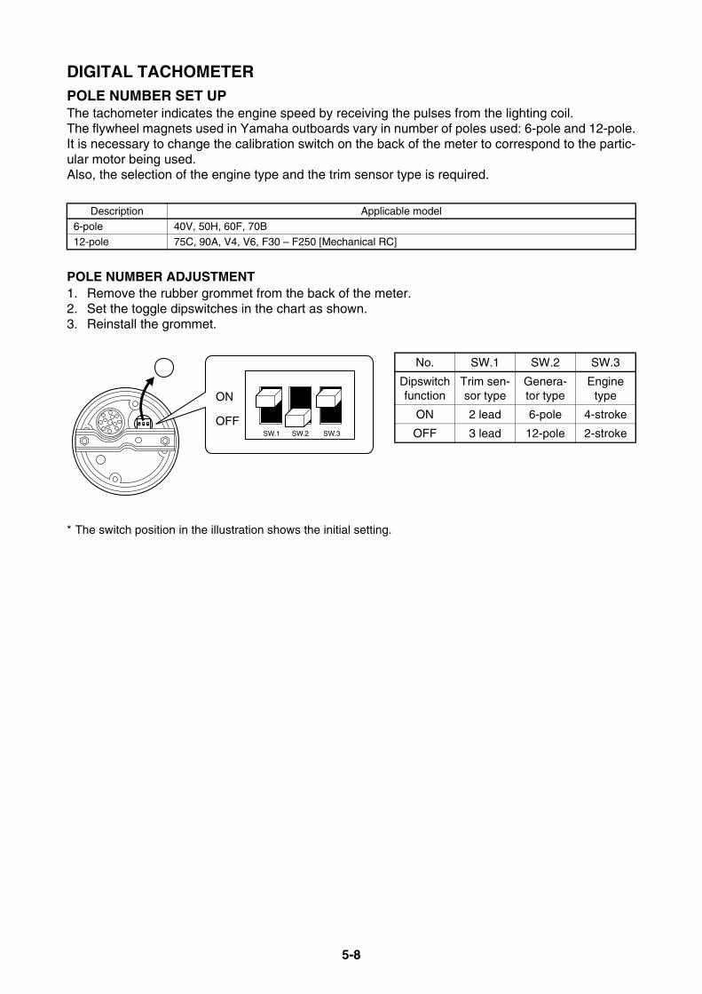
5-8
DIGITAL TACHOMETERPOLE NUMBER SET UPThe tachometer indicates the engine speed by receiving the pulses from the lighting coil.The flywheel magnets used in Yamaha outboards vary in number of poles used: 6-pole and 12-pole.It is necessary to change the calibration switch on the back of the meter to correspond to the partic-ular motor being used.Also, the selection of the engine type and the trim sensor type is required.
POLE NUMBER ADJUSTMENT1. Remove the rubber grommet from the back of the meter.2. Set the toggle dipswitches in the chart as shown.3. Reinstall the grommet.
* The switch position in the illustration shows the initial setting.
Description Applicable model6-pole 40V, 50H, 60F, 70B
12-pole 75C, 90A, V4, V6, F30 – F250 [Mechanical RC]
No. SW.1 SW.2 SW.3
Dipswitch function
Trim sen-sor type
Genera-tor type
Engine type
ON 2 lead 6-pole 4-stroke
OFF 3 lead 12-pole 2-stroke
ON
OFFSW.1 SW.2 SW.3

5-9
SPEEDOMETERThe speedometer indicates an approximate speed of the boat through the water by measuring theimpact force of the water with a pressure gauge.This impact force will vary with the density of the water and the speed of the impact.The density can vary by the purity of the water and the temperature of water.The speed of water impact can vary by the location of the speed sensor and its relation to the waterflow off the area of the boat in front of the sensor.Because of these variables, the true speed of a boat can vary from the indicated speed on themeter.Especially, the digital speedometer uses LCD readouts for speed, clock, trip distance, fuel tanklevel, and warning information for low fuel level and abnormal battery voltage.The speed can be calibrated for mph, km/h, and knots.
SPEEDOMETER TYPES AND APPLICATIONS
Ref. No. Description Part No. Applicable model
1 Digital multifunction6Y5-83570-S6
Above 40 (3-cyl)Above F30 [Mechanical RC]
6Y5-83500-30 For Yamaha manufactured boats (Japan)
2
Analog, BLK panel0 – 75 mph (20 – 120 km/h)
6Y7-83510-00
Above 40 (3-cyl)Above F30 [Mechanical RC]
Analog, WHT panel0 – 75 mph (20 – 120 km/h)
6Y7-83510-10
3
Analog, BLK panel0 – 50 mph (20 – 80 km/h)
6Y7-83510-20
Analog, WHT panel0 – 50 mph (20 – 80 km/h)
6Y7-83510-30
4
Analog, BLK panel0 – 120 km/h (15 – 65 knot)
6Y7-83510-40
Analog, WHT panel0 – 120 km/h (15 – 65 knot)
6Y7-83510-50
5
Analog, BLK panel0 – 80 km/h (10 – 43 knot)
6Y7-83510-60
Analog, WHT panel0 – 80 km/h (10 – 43 knot)
6Y7-83510-70
set mode
TRIP TIME BATT
km/hknotmph
kmmile
SPEED
1 2 3 4 5

5-10
SPEEDOMETERSPEEDOMETER DIMENSIONS
* A 6 m (19 ft) water tube (P/N: 688-83557-00) is included in all speedometer units (except digital speedome-ter unit P/N: 6Y5-83570-S6).
WATER PRESSURE DAMPER (OP)Installing the water pressure damper between the gauge and water tube is recommended under fol-lowing condition.• To reduce a risk if water has leaked at connector end causing the gauge damage.• The pointer of analog gauge is wiggled if water pressure pulsates.
93 (
3.66
)
11.2(0.44)
52(2.05)
41.9(1.65)
84.5
(3.
33)
97 (
3.82
)
8.5(0.33)
65.5(2.59)
210(8.27)
25 (0.98)
R Y B L W B
84.5
(3.
33)
Digital Analogmm (in.)
Clamp90465-11M10
Water Pressure Damper6Y5-83728-00
Water Tube6Y5-83557-31

5-11
SPEEDOMETERSPEEDOMETER TUBE ROUTING
1. Cut off about 3 mm (0.12 in.) from the endof the nipple of the speedometer tube toopen it.
2. Route the speedometer tube carefully toavoid crimping or damage.
3. Connect the tube to the nipple.* The optional speed sensor (P/N: 688-83556-
01) is required if the speedometer tube is notequipped to the clamp bracket area.
* In high-performance applications where theengine has been mounted in an elevatedposition, it may be necessary to use theoptional speed sensor to obtain a correctreading.
DIGITAL SPEEDOMETER SET UP1. Remove the rubber grommet from the back
of the meter.2. Set the toggle dipswitches in the chart as
below.3. Reinstall the grommet.
* The switch position in the illustration shows theinitial setting, which is the mph display and ABYCfuel sensor.
Cut off 3 mm (0.12 in.)
(1) Optional speed sensor
SW.1 ON OFF OFFSW.2 ON ON OFF
Display km/h mph knot/h
SW.3 ON OFF OFFSW.4 ON ON OFF
Fuel sensor
Yamaha original
5 – 105 Ω
ABYC (US)
30 – 240 Ω
Europe 180 – 0 Ω

5-12
FUEL MANAGEMENT GAUGEThe fuel management gauge has the functions as a fuel flow gauge, fuel consumption gauge, fueleconomy gauge, twin engine RPM synchronizer for dual installations, and an optional water separa-tor warning indicator that detects water in the fuel filter. The gauge can display by receiving data from the fuel flow sensor and either an NMEA 0183 com-patible GPS unit or the digital speedometer.* Fuel management gauge with speedometer does not have the function as twin engine RPM synchronizer,
water detection warning, and each engine’s fuel measurement.
FUEL MANAGEMENT GAUGE TYPES AND APPLICATIONS
FUEL MGT GAUGE KIT CONTENTS
ADDITIONAL PARTS REQUIREMENTS (FOR FUEL MGT w/ speedometer)
OPTIONAL WIRE-HARNESS
Ref. No. Description Part No. Applicable model
1
Fuel mgt gauge kit 1For single-engine
6Y5-W0088-54
Above 115Above F115 [Mechanical RC]
Fuel mgt gauge kit 2For twin-engine
6Y5-W0088-65
2 Fuel mgt gauge with speedometer 6Y5-83500-40
Description Part No.Q’ty
RemarksKit 1 Kit 2
Fuel mgt gauge 6Y5-8350F-01 1 1 w/ 3-prong connectorEXT wire-harness 6Y5-83553-F1 1 1 8 m (26 ft)
Fuel flow sensor 6Y5-85752-02 1 2
EXT wire-lead 6Y5-82117-00 1 1 30 cm (1 ft) (BLK)Screw 90158-06003 2 4
Wire-lead 703-82531-00 — 1 70 cm (2.3 ft) (BLK)
Installation manual 6Y5-2819K-F0 1 1
Description Part No. Q’ty Remarks
Fuel flow sensor 6Y5-85752-02 1EXT wire-harness 6Y5-83553-F1 1 8 m (26 ft)
Screw 90158-06003 2
Description Part No. Remarks
GPS signal lead 6Y5-85721-F0 To connect an NMEA0183 compatible GPS unit
set mode
TTL ECON SYNC
l/hgph
km/lmpg
FUEL MANAGEMENT
P S
1 2
set mode
km/hknotsmph
CPS
mile Vmpgph
TRIPFLOWECOM
TTL
SPEED FUEL
km/l/hBAT
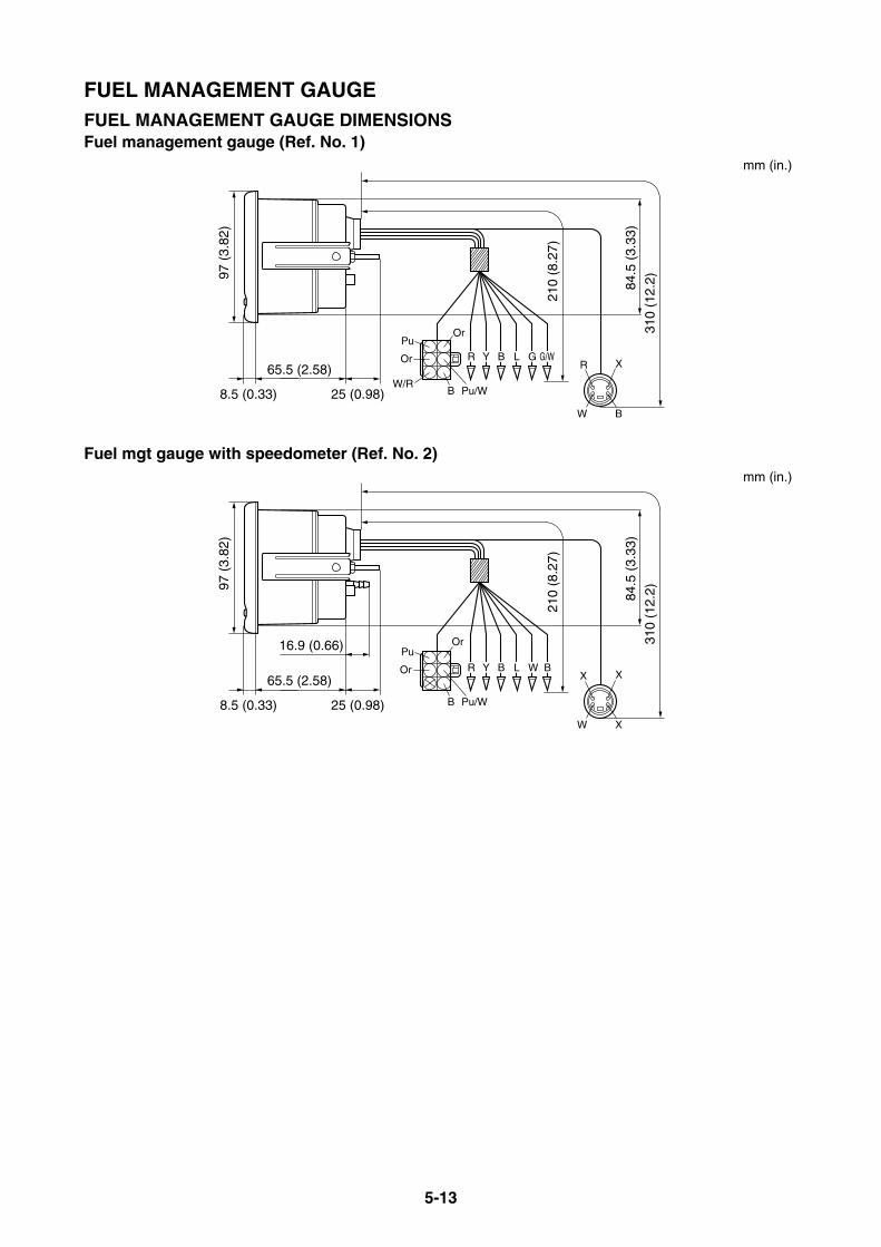
5-13
FUEL MANAGEMENT GAUGEFUEL MANAGEMENT GAUGE DIMENSIONSFuel management gauge (Ref. No. 1)
Fuel mgt gauge with speedometer (Ref. No. 2)
97 (
3.82
)
8.5 (0.33) 25 (0.98)
65.5 (2.58)
84.5
(3.
33)
310
(12.
2)
210
(8.2
7)
PuOr
Or
Pu/WW/R
B
R Y B L G G/WXR
W B
mm (in.)
97 (
3.82
)
8.5 (0.33) 25 (0.98)
65.5 (2.58)
16.9 (0.66)84
.5 (
3.33
)31
0 (1
2.2)
210
(8.2
7)
PuOr
Or
Pu/WB
R Y B L WXX
W X
B
mm (in.)

5-14
FUEL MANAGEMENT GAUGEFUEL SENSOR INSTALLATION
Follow the notifications below.1. Locate the sensor in a well ventilated area in boat between the engine and a water separator.2. Place the sensor with the “UP” mark facing upward.3. Use a fuel joint that is fitted to the fuel hose of the outboard motor.4. Secure all fuel hose ends with a hose clamp with good anti-corrosion performance.
* For twin engine application, refer to Wiring diagram in this chapter.See the installation manual in the package for further information.
INUP
OUT
To extension wire lead
Water separator(Market obtainable)
B (–)
Pu (S)
Or (+)
Fuel flow sensor
Fuel valve
IN OUT
Primer bulb
Clamp
Clamp
Fuel tank
Nipple1/4-18NPT(Market obtainable)
Inboard area
To extension wire lead if water detection switch is incorporated.
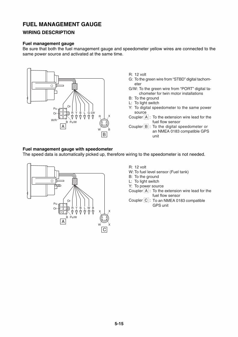
5-15
FUEL MANAGEMENT GAUGEWIRING DESCRIPTION
Fuel management gaugeBe sure that both the fuel management gauge and speedometer yellow wires are connected to thesame power source and activated at the same time.
Fuel management gauge with speedometerThe speed data is automatically picked up, therefore wiring to the speedometer is not needed.
R: 12 voltG: To the green wire from “STBD” digital tachom-
eterG/W: To the green wire from “PORT” digital ta-
chometer for twin motor installationsB: To the groundL:Y: To digital speedometer to the same power
sourceCoupler A : To the extension wire lead for the
fuel flow sensorCoupler B : To the digital speedometer or
an NMEA 0183 compatible GPS unit
PuOr
Or
Pu/WW/R
B
R
A
B
Y B L G G/WXR
W B
To light switch
R: 12 voltW: To fuel level sensor (Fuel tank)B: To the groundL: To light switchY: To power sourceCoupler A : To the extension wire lead for the
fuel flow sensorCoupler C : To an NMEA 0183 compatible
GPS unitPuOr
Or
Pu/WB
R
A
C
Y B L W BXX
W X
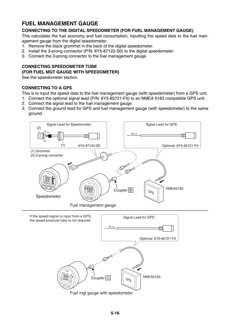
5-16
FUEL MANAGEMENT GAUGECONNECTING TO THE DIGITAL SPEEDOMETER (FOR FUEL MANAGEMENT GAUGE)This calculates the fuel economy and fuel consumption, inputting the speed data to the fuel man-agement gauge from the digital speedometer.1. Remove the black grommet in the back of the digital speedometer.2. Install the 3-prong connector (P/N: 6Y5-87122-S0) to the digital speedometer.3. Connect the 3-prong connector to the fuel management gauge.
CONNECTING SPEEDOMETER TUBE (FOR FUEL MGT GAUGE WITH SPEEDOMETER)See the speedometer section.
CONNECTING TO A GPSThis is to input the speed data to the fuel management gauge (with speedometer) from a GPS unit.1. Connect the optional signal lead (P/N: 6Y5-85721-F0) to an NMEA 0183 compatible GPS unit.2. Connect the signal lead to the fuel management gauge.3. Connect the ground lead for GPS and fuel management gauge (with speedometer) to the same
ground.
set mode
TTL ECON SYNC
l/hgph
km/lmpg
FUEL MANAGEMENT
YAMAHA
P S
set mode
TRIP TIME BATT
km/hknotmphkmmile
SPEED
YAMAHA
GPSSpeedometer
B
(2)
6Y5-87122-S0
NMEA0183
NMEA0183
Optional: 6Y5-85721-F0
Signal Lead for Speedometer Signal Lead for GPS
123
R
W
Fuel management gauge
(1)
(1) Grommet(2) 3-prong connector
W (+)
Coupler B
GPS
Optional: 6Y5-85721-F0
Signal Lead for GPS
Fuel mgt gauge with speedometer
W (+)
Coupler C
set mode
km/hknotsmph
CPS
mile Vmpgph
TRIPFLOWECOM
TTL
SPEED FUEL
km/l/hBAT
If the speed signal is input from a GPS, the speed pressure tube is not required.
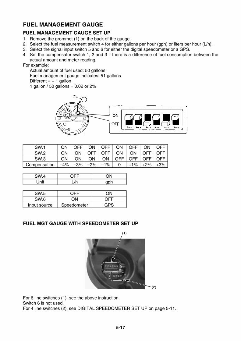
5-17
FUEL MANAGEMENT GAUGEFUEL MANAGEMENT GAUGE SET UP1. Remove the grommet (1) on the back of the gauge.2. Select the fuel measurement switch 4 for either gallons per hour (gph) or liters per hour (L/h).3. Select the signal input switch 5 and 6 for either the digital speedometer or a GPS.4. Set the compensator switch 1, 2 and 3 if there is a difference of fuel consumption between the
actual amount and meter reading.For example:
Actual amount of fuel used: 50 gallonsFuel management gauge indicates: 51 gallonsDifferent = + 1 gallon1 gallon / 50 gallons = 0.02 or 2%
FUEL MGT GAUGE WITH SPEEDOMETER SET UP
For 6 line switches (1), see the above instruction.Switch 6 is not used.For 4 line switches (2), see DIGITAL SPEEDOMETER SET UP on page 5-11.
SW.1 ON OFF ON OFF ON OFF ON OFFSW.2 ON ON OFF OFF ON ON OFF OFFSW.3 ON ON ON ON OFF OFF OFF OFF
Compensation –4% –3% –2% –1% 0 +1% +2% +3%
SW.4 OFF ONUnit L/h gph
SW.5 OFF ONSW.6 ON OFF
Input source Speedometer GPS
(1)
(2)

5-18
ANALOG TRIM METERThe trim meter shows the trim angle of the outboard motor.
ANALOG TRIM METER APPLICATIONS
(*1) Mechanical RC(*2) T25 for US/CA
ANALOG TRIM METER DIMENSIONS
TRIM SENSOR ADJUSTMENTFor a down position adjustment, loosen the trim sensor screw and make an adjustment so that theneedle aligns with the marking line indicating “DOWN”.
Ref. No. Description Part No. Applicable model
1
4-pin couplerBLK panel
6Y7-83670-00Above premixed 40 (3-cyl) w/ PTT, 250G/ L250G
Bullet connectorBLK panel
6Y7-83670-40Above 40 (3-cyl) w/ oil injection & PTT (except 250G/L250G), Above F30 w/ PTT (*1), T25 (*2)
Using as a set with tachometer, 6Y7-83540-80
2
4-pin couplerWHT panel
6Y7-83670-20 Premixed 40 (3-cyl)-225 w/ PTT, 250G/L250G
Bullet connectorWHT panel
6Y7-83670-50Above 40 (3-cyl) w/ oil injection & PTT (except 250G/L250G), Above F30 w/ PTT (*1), T25 (*2)
Using as a set with tachometer, 6Y7-83540-90
21
60 (
2.36
)
11 (0.43) 13.7(0.54)
46.6 (1.83)
52 (
2.05
)
200 (7.87)
200 (7.87)
B
B
L
Y
x
x
B
P
60 (
2.36
)
11 (0.43) 13.7(0.54)
46.6 (1.83)
52 (
2.05
)
200 (7.87)
300 (11.8)
200 (7.87)
B
P
B
L
Y
With 4-pin coupler With bullet connectormm (in.)mm (in.)

5-19
COOLANT PRESSURE METERThe coolant pressure meter shows the water pressure of cooling water passage, and provides awarning for the operator when there is a problem with the cooling system.* For all in-line cylinder models, the position for installing the sensor shares the coolant temperature output.
Therefore, either the coolant temperature meter or the coolant pressure meter can be used for one engine.* However, on V4, V6, and F150 models, both meters can be used for one engine.
COOLANT PRESSURE METER APPLICATIONS
ADDITIONAL PARTS REQUIREMENTS
COOLANT PRESSURE METER DIMENSIONS
COOLANT PRESS. ATTACHMENT INSTALLATIONThe method for installing the coolant pressure attachment is the same as the coolant temperaturesensor. See the installation instruction to the sensor in the coolant temperature meter on page 5-21.
Ref. No. Description Part No. Applicable model
1kPa, Black panel 6Y7-83660-00
Above 40 [3-cyl]Above F25 (FT/T25) [Mechanical RC]
kPa, White panel 6Y7-83660-20
2psi, Black panel 6Y7-83660-10
psi, White panel 6Y7-83660-30
Description Part No. Remarks
Coolant pressure attachment 688-83667-00 With 10 m (32 ft) tube
1 2
60 (
2.36
)
11 (0.43) 18.9 (0.74)
42 (1.65)
52 (
2.05
)
mm (in.)
To meter
M14 X 1.5
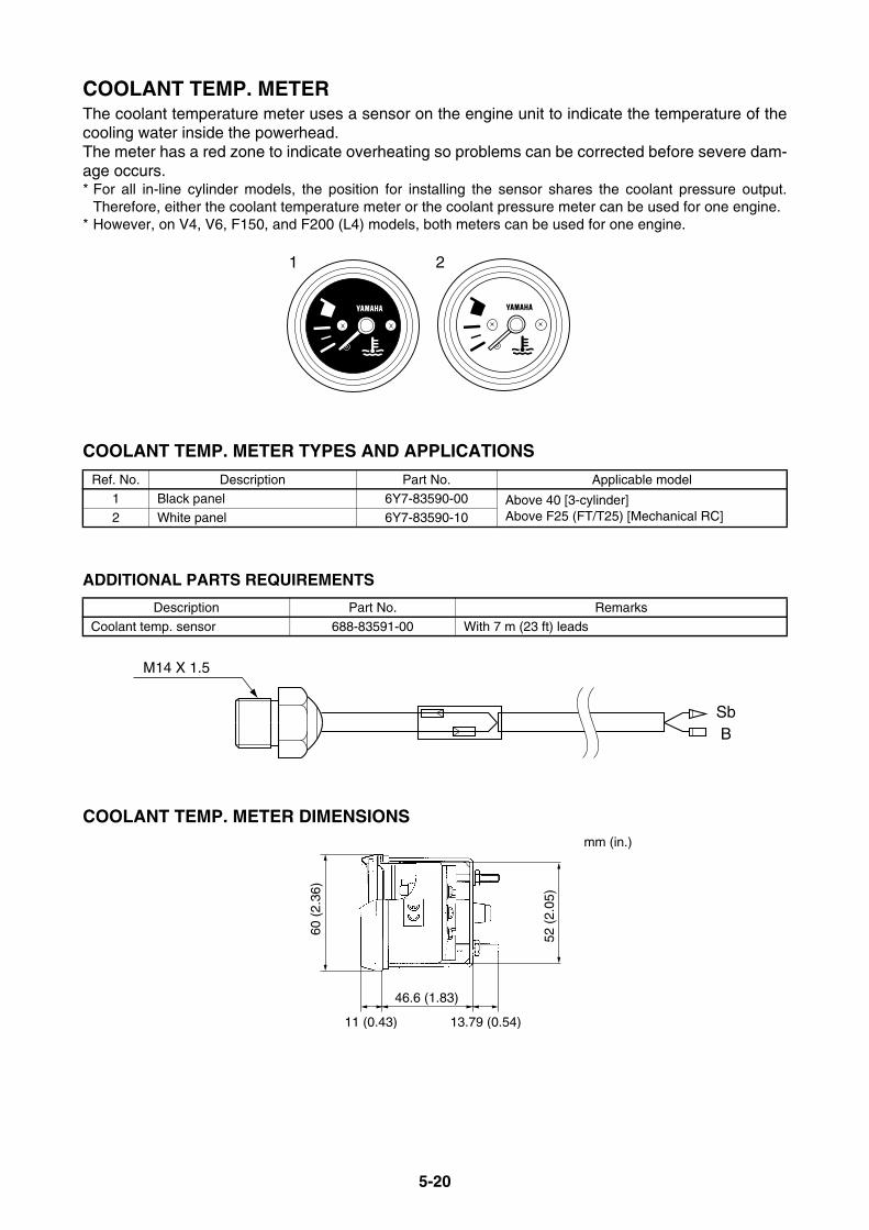
5-20
COOLANT TEMP. METERThe coolant temperature meter uses a sensor on the engine unit to indicate the temperature of thecooling water inside the powerhead. The meter has a red zone to indicate overheating so problems can be corrected before severe dam-age occurs.* For all in-line cylinder models, the position for installing the sensor shares the coolant pressure output.
Therefore, either the coolant temperature meter or the coolant pressure meter can be used for one engine.* However, on V4, V6, F150, and F200 (L4) models, both meters can be used for one engine.
COOLANT TEMP. METER TYPES AND APPLICATIONS
ADDITIONAL PARTS REQUIREMENTS
COOLANT TEMP. METER DIMENSIONS
Ref. No. Description Part No. Applicable model1 Black panel 6Y7-83590-00 Above 40 [3-cylinder]
Above F25 (FT/T25) [Mechanical RC]2 White panel 6Y7-83590-10
Description Part No. Remarks
Coolant temp. sensor 688-83591-00 With 7 m (23 ft) leads
1 2
SbB
M14 X 1.5
60 (
2.36
)
11 (0.43) 13.79 (0.54)
46.6 (1.83)
52 (
2.05
)
mm (in.)
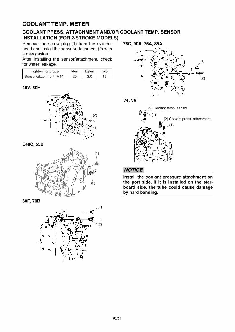
5-21
COOLANT TEMP. METERCOOLANT PRESS. ATTACHMENT AND/OR COOLANT TEMP. SENSOR INSTALLATION (FOR 2-STROKE MODELS)Remove the screw plug (1) from the cylinderhead and install the sensor/attachment (2) witha new gasket.After installing the sensor/attachment, checkfor water leakage.
40V, 50H
E48C, 55B
60F, 70B
75C, 90A, 75A, 85A
V4, V6
NOTICEInstall the coolant pressure attachment onthe port side. If it is installed on the star-board side, the tube could cause damageby hard bending.
Tightening torque N•m kgf•m ft•lb
Sensor/attachment (M14) 20 2.0 15
(1)
(2)
(1)
(2)
(1)
(2)
(1)
(2)
(1)
(1)
(2) Coolant temp. sensor
(2) Coolant press. attachment
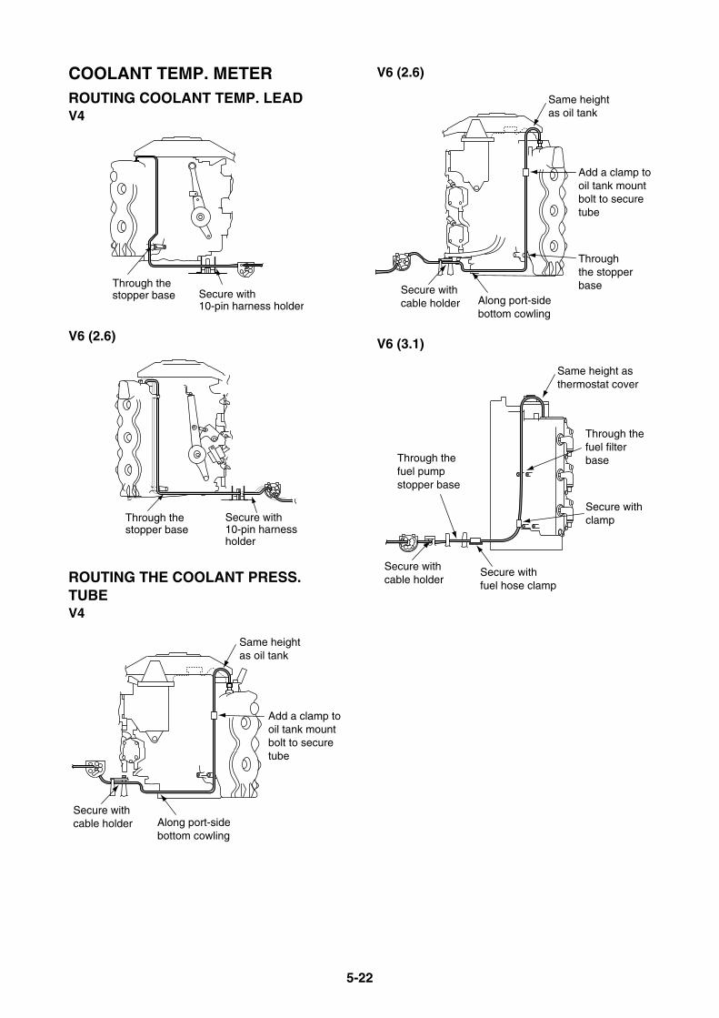
5-22
COOLANT TEMP. METERROUTING COOLANT TEMP. LEADV4
V6 (2.6)
ROUTING THE COOLANT PRESS. TUBEV4
V6 (2.6)
V6 (3.1)
Through thestopper base Secure with
10-pin harness holder
Through thestopper base
Secure with10-pin harnessholder
Secure withcable holder Along port-side
bottom cowling
Add a clamp tooil tank mountbolt to secure tube
Same height as oil tank
Secure withcable holder Along port-side
bottom cowling
Add a clamp tooil tank mountbolt to secure tube
Same height as oil tank
Through the stopperbase
Secure withcable holder
Through thefuel filterbase
Same height as thermostat cover
Through the fuel pump stopper base
Secure withfuel hose clamp
Secure withclamp
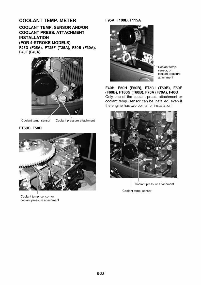
5-23
COOLANT TEMP. METERCOOLANT TEMP. SENSOR AND/OR COOLANT PRESS. ATTACHMENT INSTALLATION (FOR 4-STROKE MODELS)F25D (F25A), FT25F (T25A), F30B (F30A),F40F (F40A)
FT50C, F50D
F95A, F100B, F115A
F40H, F50H (F50B), FT50J (T50B), F60F(F60B), FT60G (T60B), F70A (F70A), F40GOnly one of the coolant press. attachment orcoolant temp. sensor can be installed, even ifthe engine has two points for installation.
Coolant pressure attachmentCoolant temp. sensor
Coolant temp. sensor, orcoolant pressure attachment
Coolant temp.sensor, or coolant pressure attachment
Coolant pressure attachment
Coolant temp. sensor
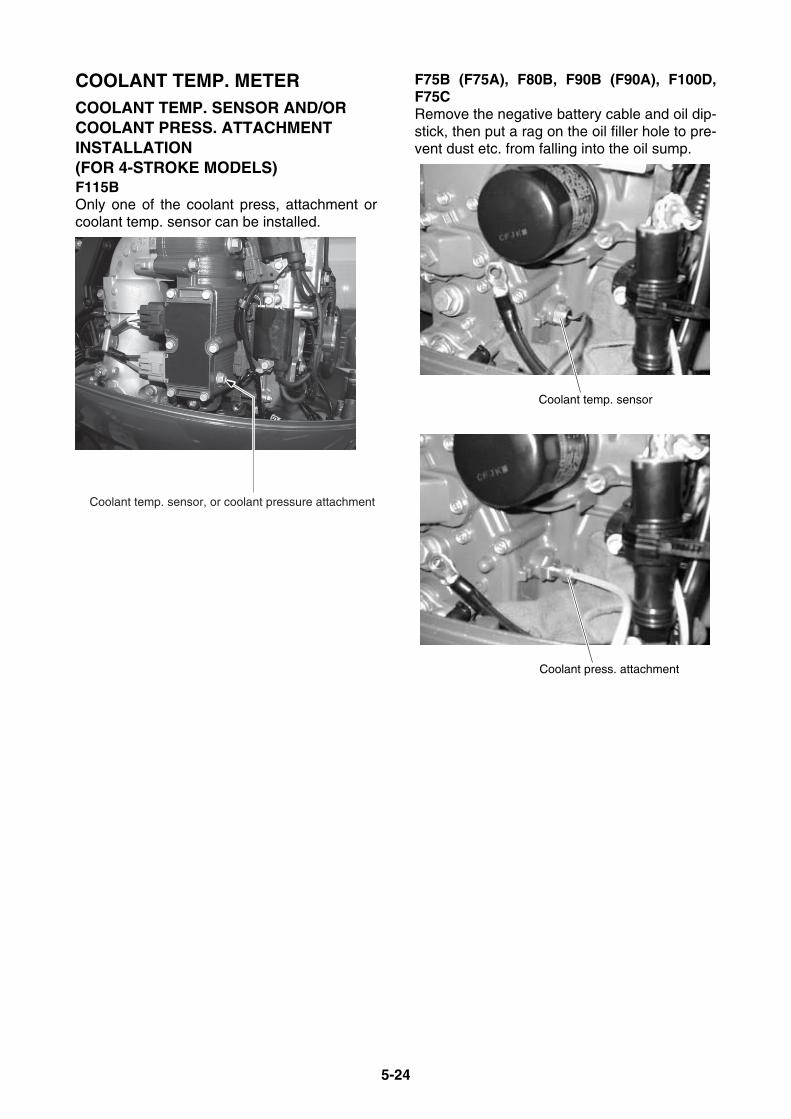
5-24
COOLANT TEMP. METERCOOLANT TEMP. SENSOR AND/OR COOLANT PRESS. ATTACHMENT INSTALLATION (FOR 4-STROKE MODELS)F115BOnly one of the coolant press, attachment orcoolant temp. sensor can be installed.
F75B (F75A), F80B, F90B (F90A), F100D,F75CRemove the negative battery cable and oil dip-stick, then put a rag on the oil filler hole to pre-vent dust etc. from falling into the oil sump.
Coolant temp. sensor, or coolant pressure attachment
Coolant temp. sensor
Coolant press. attachment
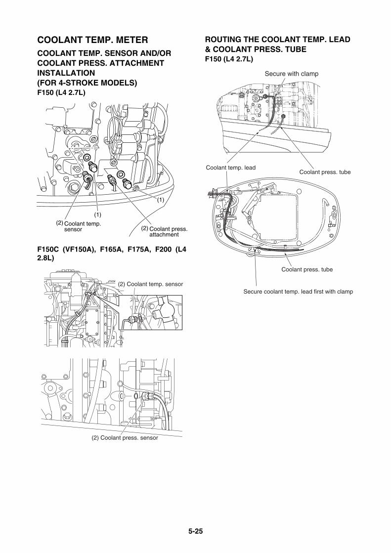
5-25
COOLANT TEMP. METERCOOLANT TEMP. SENSOR AND/OR COOLANT PRESS. ATTACHMENT INSTALLATION (FOR 4-STROKE MODELS)F150 (L4 2.7L)
F150C (VF150A), F165A, F175A, F200 (L42.8L)
ROUTING THE COOLANT TEMP. LEAD & COOLANT PRESS. TUBEF150 (L4 2.7L)
(1)
(2)
(1)(2) Coolant temp.
sensor Coolant press.attachment
(2) Coolant temp. sensor
(2) Coolant press. sensor
Coolant temp. leadCoolant press. tube
Coolant press. tube
Secure coolant temp. lead first with clamp
Secure with clamp

5-26
COOLANT TEMP. METERROUTING THE COOLANT TEMP. LEAD & COOLANT PRESS. TUBEF150C (VF150A), F165A, F175A, F200 (L42.8L)
SENSOR/ATTACHMENT INSTALLATION AND ROUTINGF200, F225, F250 (V6) [Mechanical RC] w/ Variable Camshaft Timing
Secure with clamp
Coolant temp. sensor
Coolant temp. lead
Coolant press. tube
Coolant temp. lead
Coolant press. tube
Coolant temp. lead
Coolant temp. sensorCoolant temp. sensorCoolant temp. sensor
Coolant press. Coolant press. attachmentattachmentCoolant press. attachment
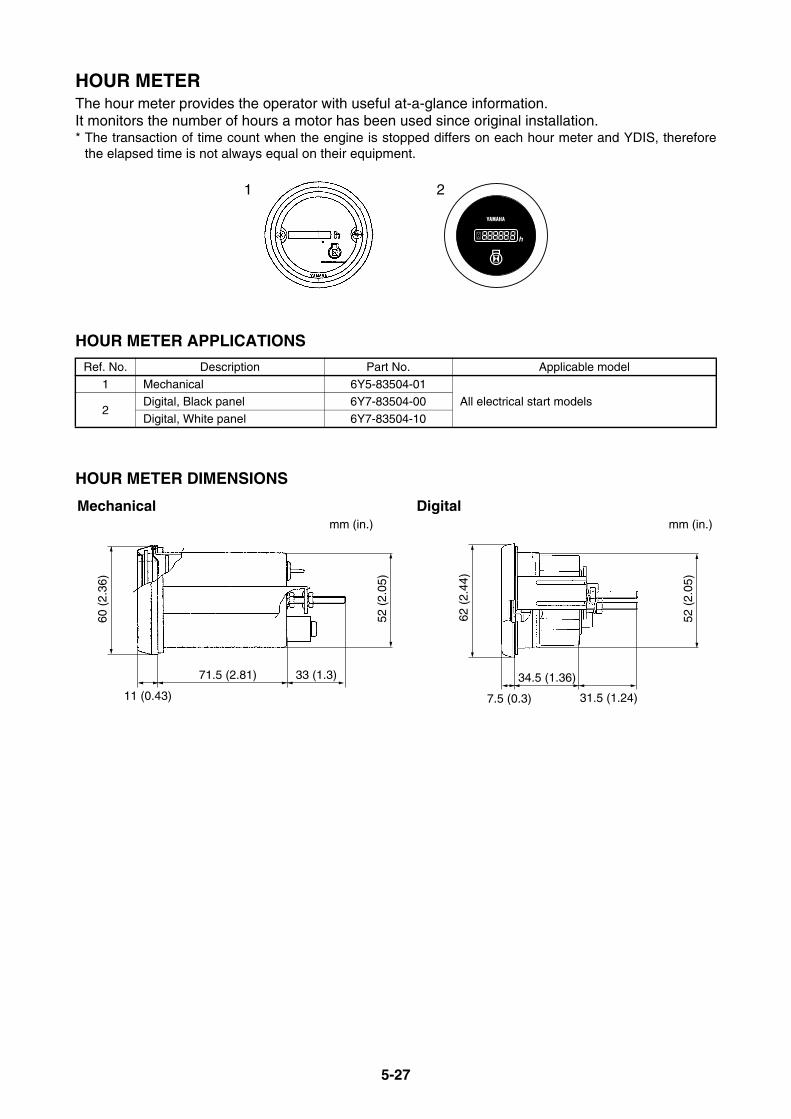
5-27
HOUR METERThe hour meter provides the operator with useful at-a-glance information.It monitors the number of hours a motor has been used since original installation.* The transaction of time count when the engine is stopped differs on each hour meter and YDIS, therefore
the elapsed time is not always equal on their equipment.
HOUR METER APPLICATIONS
HOUR METER DIMENSIONS
Ref. No. Description Part No. Applicable model
1 Mechanical 6Y5-83504-01All electrical start models
2Digital, Black panel 6Y7-83504-00
Digital, White panel 6Y7-83504-10
21
7.5 (0.3)
34.5 (1.36)
31.5 (1.24)52
(2.
05)
62 (
2.44
)
60 (
2.36
)
11 (0.43)
71.5 (2.81) 33 (1.3)
52 (
2.05
)
Mechanical Digitalmm (in.)mm (in.)

5-28
HOUR METERWIRING THE MECHANICAL HOUR METERThe hour meter counts while the ignition switch is “ON”.
WIRING THE DIGITAL HOUR METERTwo counting methods can be selected by connecting wires.
Y
Y
B
B
BL
Batt.+12V
Battery
GND
IG switch
Lamp switch
Hour meter
L
IG switch
Batt.+12V
GND
BatteryLighting Coil(alternator)
Hour meter
Positive Negative
Tach signal
Y
Y B
B
G
G
IG switch
Batt.+12V
GND
Battery
Hour meter
Positive Negative
Power signal
Y
Y B
B
G
COUNTING TIME WHILE ENGINE IS RUNNING COUNTING TIME WHILE IG SWITCH IS “ON”
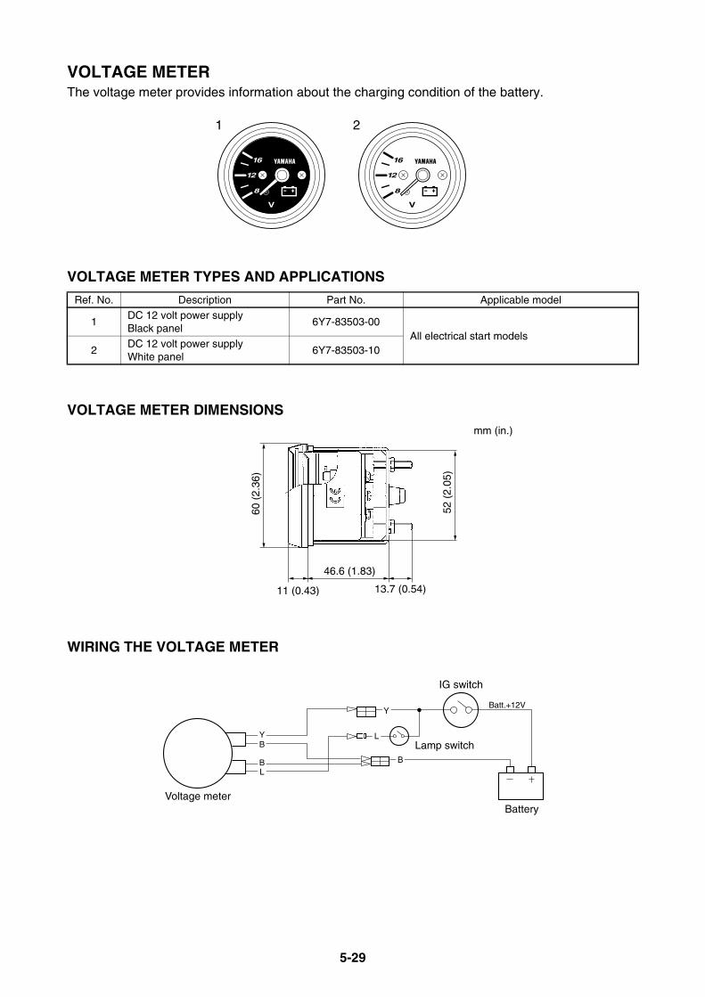
5-29
VOLTAGE METERThe voltage meter provides information about the charging condition of the battery.
VOLTAGE METER TYPES AND APPLICATIONS
VOLTAGE METER DIMENSIONS
WIRING THE VOLTAGE METER
Ref. No. Description Part No. Applicable model
1DC 12 volt power supplyBlack panel
6Y7-83503-00All electrical start models
2DC 12 volt power supplyWhite panel
6Y7-83503-10
1 2
60 (
2.36
)
11 (0.43)
46.6 (1.83)
13.7 (0.54)
52 (
2.05
)
mm (in.)
YB
BL
Battery
IG switch
Voltage meter
Batt.+12VY
B
Lamp switchL
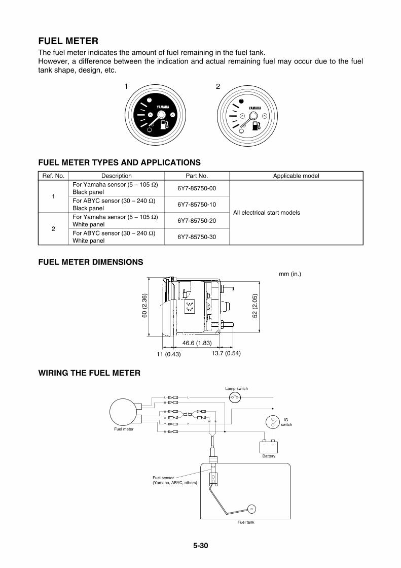
5-30
FUEL METERThe fuel meter indicates the amount of fuel remaining in the fuel tank.However, a difference between the indication and actual remaining fuel may occur due to the fueltank shape, design, etc.
FUEL METER TYPES AND APPLICATIONS
FUEL METER DIMENSIONS
WIRING THE FUEL METER
Ref. No. Description Part No. Applicable model
1
For Yamaha sensor (5 – 105 Ω)Black panel
6Y7-85750-00
All electrical start models
For ABYC sensor (30 – 240 Ω)Black panel
6Y7-85750-10
2
For Yamaha sensor (5 – 105 Ω)White panel
6Y7-85750-20
For ABYC sensor (30 – 240 Ω)White panel
6Y7-85750-30
21
60 (
2.36
)
11 (0.43)
46.6 (1.83)
13.7 (0.54)
52 (
2.05
)
mm (in.)
L
BW
Fuel sensor(Yamaha, ABYC, others)
Battery
Fuel meter
Fuel tank
B
B
W
Y
L
Y
B
Lamp switch
IG switch

5-31
CHARGE WARNING UNITThe lamp of the charge warning unit indicates the status of charging the battery.When the main switch is turned to “ON” position, the red lamp lights.After the engine starts, the lamp will go off.If the charging system has malfunctioned, the lamp will light.
CHARGE WARNING UNIT TYPES AND APPLICATIONS
ADDITIONAL PARTS REQUIREMENTS
WIRING THE CHARGE WARNING UNIT
Description Part No. Remarks
Relay 697-81901-60 All electrical start models with a rectifier/regulator
Description Part No. Remarks
Red lamp 663-84301-01 12V
R
84 (
3.31
)
40 (1.57)
7.7 (0.30)
GBGY
300 (11.81)
mm (in.)
20 (0.79)
500 (19.69)
RG
10 (
0.39
)42
(1.
65)
mm (in.)
G
GR
Y
B
Battery
IG switch
Charge warning unit
Lamp
Lighting coil
Relay
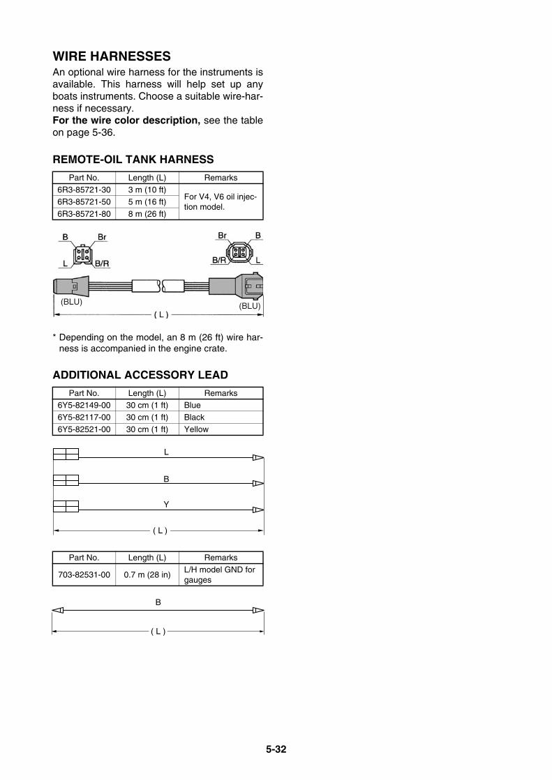
5-32
WIRE HARNESSESAn optional wire harness for the instruments isavailable. This harness will help set up anyboats instruments. Choose a suitable wire-har-ness if necessary. For the wire color description, see the tableon page 5-36.
REMOTE-OIL TANK HARNESS
* Depending on the model, an 8 m (26 ft) wire har-ness is accompanied in the engine crate.
ADDITIONAL ACCESSORY LEAD
Part No. Length (L) Remarks
6R3-85721-30 3 m (10 ft)For V4, V6 oil injec-tion model.
6R3-85721-50 5 m (16 ft)
6R3-85721-80 8 m (26 ft)
Part No. Length (L) Remarks6Y5-82149-00 30 cm (1 ft) Blue
6Y5-82117-00 30 cm (1 ft) Black
6Y5-82521-00 30 cm (1 ft) Yellow
Part No. Length (L) Remarks
703-82531-00 0.7 m (28 in)L/H model GND for gauges
(BLU) (BLU)
( L )
Y
B
L
( L )
( L )
B
( L )
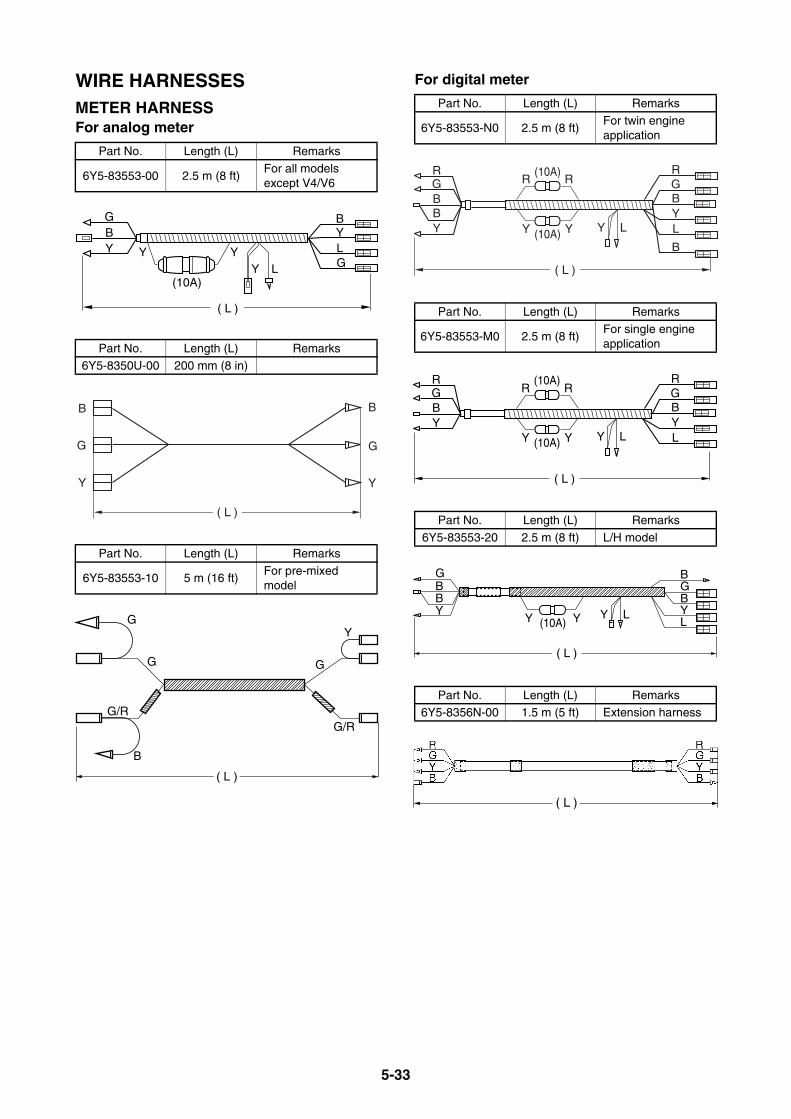
5-33
WIRE HARNESSESMETER HARNESSFor analog meter
For digital meter
Part No. Length (L) Remarks
6Y5-83553-00 2.5 m (8 ft)For all models except V4/V6
Part No. Length (L) Remarks6Y5-8350U-00 200 mm (8 in)
Part No. Length (L) Remarks
6Y5-83553-10 5 m (16 ft)For pre-mixed model
BYLGLY
GBY
(10A)
Y Y
( L )
( L )
B
G
Y
B
G
Y
( L )
( L )
G
G
Y
G
G/RG/R
B
Part No. Length (L) Remarks
6Y5-83553-N0 2.5 m (8 ft)For twin engine application
Part No. Length (L) Remarks
6Y5-83553-M0 2.5 m (8 ft)For single engine application
Part No. Length (L) Remarks
6Y5-83553-20 2.5 m (8 ft) L/H model
Part No. Length (L) Remarks6Y5-8356N-00 1.5 m (5 ft) Extension harness
RR R
Y Y Y L
RGBYL
B
GBBY
( L )
(10A)
(10A)
RR R
Y Y Y L
RGBYL
GBY
( L )
(10A)
(10A)
Y L
GBBY
Y Y
BGBYL
( L )
(10A)
( L )
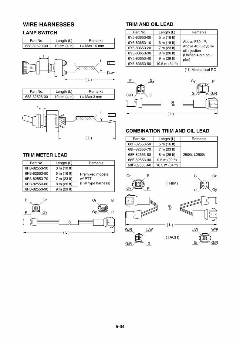
5-34
WIRE HARNESSESLAMP SWITCH
TRIM METER LEAD
TRIM AND OIL LEAD
(*1) Mechanical RC
COMBINATION TRIM AND OIL LEAD
Part No. Length (L) Remarks688-82520-00 10 cm (4 in) t = Max.15 mm
Part No. Length (L) Remarks688-82526-00 10 cm (4 in) t = Max.3 mm
Part No. Length (L) Remarks
6R3-82553-30 3 m (10 ft)
Premixed models w/ PTT(Flat type harness)
6R3-82553-50 5 m (16 ft)
6R3-82553-70 7 m (23 ft)
6R3-82553-80 8 m (26 ft)6R3-82553-90 9 m (29 ft)
tL
Y
( L )
t
L
Y
( L )
GyP
OrB
PGy
BOr
( L )
Part No. Length (L) Remarks6Y5-83653-00 5 m (16 ft)
Above F30 (*1), Above 40 (3-cyl) w/ oil injection (Unified 4-pin cou-pler)
6Y5-83653-10 6 m (19 ft)
6Y5-83653-20 7 m (23 ft)6Y5-83653-30 8 m (26 ft)
6Y5-83653-40 9 m (29 ft)
6Y5-83653-50 10.5 m (34 ft)
Part No. Length (L) Remarks
68F-82553-50 5 m (16 ft)
250G, L250G
68F-82553-70 7 m (23 ft)
68F-82553-80 8 m (26 ft)
68F-82553-90 9.5 m (29 ft)68F-82553-A0 10.5 m (34 ft)
GG/R
GyP PGy
G/RG
( L )
Or
Gy
B
P
B
P
Or
Gy
GG/R G/RG
( L )
(TRIM)
(TACH)
L/WW/R W/RL/W
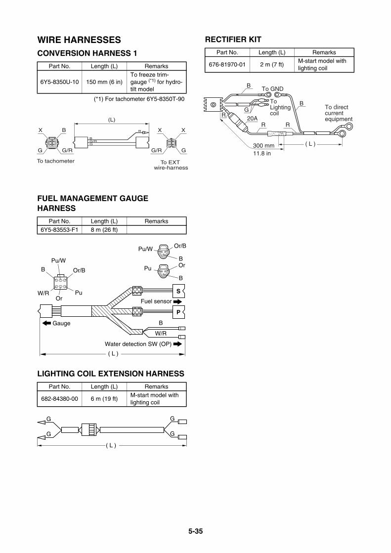
5-35
WIRE HARNESSESCONVERSION HARNESS 1
(*1) For tachometer 6Y5-8350T-90
FUEL MANAGEMENT GAUGE HARNESS
LIGHTING COIL EXTENSION HARNESS
RECTIFIER KIT
Part No. Length (L) Remarks
6Y5-8350U-10 150 mm (6 in)To freeze trim-gauge (*1) for hydro-tilt model
Part No. Length (L) Remarks
6Y5-83553-F1 8 m (26 ft)
Part No. Length (L) Remarks
682-84380-00 6 m (19 ft)M-start model with lighting coil
(L)
B
BG/RG
To tachometer To EXT wire-harness
XX
GG/R
BX
G/RG
Or/B
Or/B
B
Pu/W
Or
B
S
P
B
Fuel sensor
Gauge
W/R
Pu
W/ROr
B
Pu/W
Pu
( L )
Water detection SW (OP)
G
G
G
G
( L )
Part No. Length (L) Remarks
676-81970-01 2 m (7 ft)M-start model with lighting coil
R
300 mm11.8 in
( L )
RR20A
B
B To GND
ToLightingcoil
To direct current equipment
G

5-36
WIRING DIAGRAMSSome representative wiring diagram samples for Yamaha genuine remote controls and instrumentsare shown here. These diagrams will cover most common configurations.
WIRE COLOR CODEThe wiring color code and the main usage for the electric wires are shown below.The wire color and its main usage are different between Yamaha standard and ABYC standard.* For the wires which use tracer stripes, the main color is followed by a slash then the tracer color.
For example:R/G = Red wire with a green tracer stripePu/W = Purple wire with a white tracer stripe
Color code
Wire color Color sampleMain usage
Yamaha standard ABYC standardB Black Ground, Battery (–) GroundB/R Black/Red Remote-oil tankB/W Black/White Ignition coil primaryBr Brown Neutral switch GeneratorCh ChocolateDg Dark greenG Green Lighting coil 1 (tach signal 1)G/R Green/Red Oil warningG/W Green/White Lighting coil 2 (tach signal 2)Gy Gray Warning signal Tacho signalL Blue Instrument light, Remote choke Instrument lightLg Light green Trim downOr Orange Accessory feedOr/B Orange/BlackP Pink Overheat warning, Trim signal Fuel sensorPu Purple ECM IgnitionPu/W Purple/WhiteR Red Battery (+) Battery (+)Sb Sky blue Trim up Oil pressureV VioletW White Engine stop switchW/R White/Red Pulser coilX — Not usedY Yellow Accessory feedY/R Yellow/Red Diagnosis Starting motor
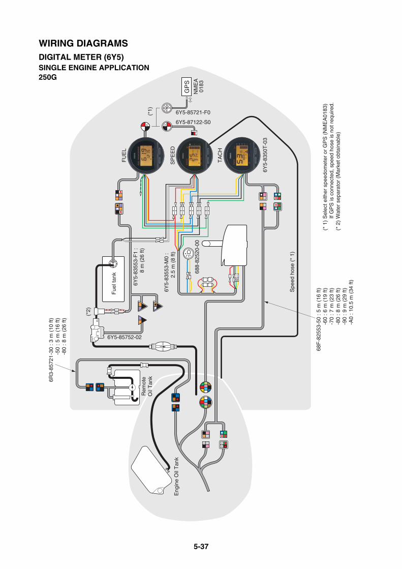
5-37
(* 1
) S
elec
t eith
er s
peed
omet
er o
r G
PS
(N
ME
A01
83)
If
GP
S is
con
nect
ed, s
peed
hos
e is
not
req
uire
d.(*
2)
Wat
er s
epar
ator
(M
arke
t obt
aina
ble)
(*1)
(*2)
Fue
l tan
k
Spe
ed h
ose
(* 1
)
OU
T
IN
688-
8252
0-00
6Y5-
8355
3-F
1 :
8 m
(26
ft)
6Y5-
8355
3-M
0 :
2.5
m (
8 ft)
6Y5-85752-02
6Y5-85721-F0
6Y5-87122-S0
68F
-825
53-5
0 : 5
m (
16 ft
)-6
0 : 6
m (
19 ft
)-7
0 : 7
m (
23 ft
)-8
0 : 8
m (
26 ft
)-9
0 : 9
m (
29 ft
)-A
0 : 1
0.5
m (
34 ft
)
6R3-
8572
1-3
0 : 3
m (
10 ft
)-5
0 : 5
m (
16 ft
)-8
0 : 8
m (
26 ft
)
6Y5-
8350
T-0
3
Eng
ine
Oil
Tan
k
FU
EL
SP
EE
D
TA
CH
Rem
ote
Oil
Tan
k
GP
SN
ME
A01
83
(+)
WIRING DIAGRAMSDIGITAL METER (6Y5)SINGLE ENGINE APPLICATION250G
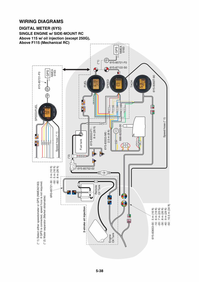
5-38
Rem
ote
Oil
Tan
k
Fue
l tan
k
OU
T
IN
2-st
roke
oil
inje
ctio
n
(*2)
6Y5-
8355
3-F
1 :
8 m
(26
ft)
6Y5-85752-02
Spe
ed h
ose
(* 1
)
6R3-
8572
1-30
: 3
m (
10 ft
)-5
0 : 5
m (
16 ft
)-8
0 : 8
m (
26 ft
)
6Y5-
8365
3-00
: 5
m (
16 ft
)-1
0 : 6
m (
19 ft
)-2
0 : 7
m (
23 ft
)-3
0 : 8
m (
26 ft
)-4
0 : 9
m (
29 ft
)-5
0 : 1
0.5
m (
34 ft
)
6Y5-
8350
T-9
0
FU
EL
SP
EE
D
TA
CH
GP
S
(*1) 6Y5-85721-F0
6Y5-87122-S0
(* 1
) S
elec
t eith
er s
peed
omet
er o
r G
PS
(N
ME
A01
83)
If
GP
S is
con
nect
ed, s
peed
hose
is n
ot r
equi
red.
(* 2
) W
ater
sep
arat
or (
Mar
ket o
btai
nabl
e)
NM
EA
0183
Eng
ine
Oil
Tan
k
688-
8252
0-00
6Y5-
8355
3-M
0 :
2.5
m (
8 ft)
GP
SN
ME
A01
83S
peed
hos
e (*
1)
6Y5-
8572
1-F
0S
PE
ED
/FU
EL
(+)
(+)
WIRING DIAGRAMSDIGITAL METER (6Y5)SINGLE ENGINE w/ SIDE-MOUNT RCAbove 115 w/ oil injection (except 250G), Above F115 (Mechanical RC)

5-39
Fue
l tan
k
OU
T
IN
(*1)
(*2)
6Y5-
8355
3-N
0 :
2.5
m (
8 ft)
688-
8252
0-00
6Y5-
8575
2-02
Spe
ed h
ose
(* 1
)
688-
8258
A-5
0 (5
m)
-60
(6 m
)-7
0 (7
m)
6K1-
8258
A-4
0 (8
m)
61B
-825
8A-0
0 (9
.5 m
)
6Y5-
8355
3-F
1 :
8 m
(26
ft)
GP
S
Rem
ote
Oil
Tan
k
TA
CH
FU
EL
Eng
ine
Oil
Tan
k
NM
EA
0183
SP
EE
D
2-st
roke
oil
inje
ctio
n
(* 1
) S
elec
t eith
er s
peed
omet
er o
r G
PS
(N
ME
A01
83)
If
GP
S is
con
nect
ed, s
peed
hos
e is
not
req
uire
d.(*
2)
Wat
er s
epar
ator
(M
arke
t obt
aina
ble)
6R3-
8572
1-30
: 3
m (
10 ft
)-5
0 : 5
m (
16 ft
)-8
0 : 8
m (
26 ft
)
6Y5-
8365
3-00
: 5
m (
16 ft
)-1
0 : 6
m (
19 ft
)-2
0 : 7
m (
23 ft
)-3
0 : 8
m (
26 ft
)-4
0 : 9
m (
29 ft
)-5
0 : 1
0.5
m (
34 ft
)
6Y5-
8572
1-F
06Y
5-87
122-
S0
6Y5-
8350
T-9
0
Spe
ed h
ose
(* 1
)
GP
SN
ME
A01
83
6Y5-
8572
1-F
0S
PE
ED
/FU
EL
(+)
(+)
WIRING DIAGRAMSDIGITAL METER (6Y5)SINGLE ENGINE W/ BINNACLE RCAbove 115 w/ oil injection (except 250G), Above F115 (Mechanical RC)
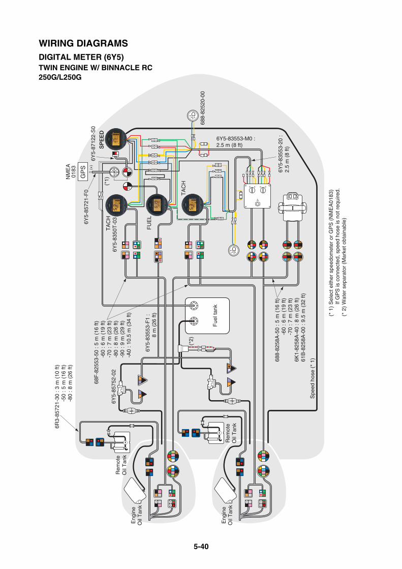
5-40
6R3-
8572
1-30
: 3
m (
10 ft
)-5
0 : 5
m (
16 ft
)-8
0 : 8
m (
26 ft
)
Fue
l tan
k
OU
T
IN
OU
T
IN
(*1)
(*2)
6Y5-83553-M0 : 2.5 m (8 ft)
688-
8252
0-00
6Y5-
8575
2-02
Spe
ed h
ose
(* 1
)688-
8258
A-5
0 : 5
m (
16 ft
)-6
0 : 6
m (
19 ft
)-7
0 : 7
m (
23 ft
)6K
1-82
58A
-40
: 8 m
(26
ft)
61B
-825
8A-0
0 : 9
.5 m
(32
ft)
6Y5-
8355
3-F
1 :
8 m
(26
ft)
6Y5-
8355
3-20
: 2.
5 m
(8
ft)
(* 1
) S
elec
t eith
er s
peed
omet
er o
r G
PS
(N
ME
A01
83)
If
GP
S is
con
nect
ed, s
peed
hos
e is
not
req
uire
d.(*
2)
Wat
er s
epar
ator
(M
arke
t obt
aina
ble)
68F
-825
53-5
0 : 5
m (
16 ft
)-6
0 : 6
m (
19 ft
)-7
0 : 7
m (
23 ft
)-8
0 : 8
m (
26 ft
)-9
0 : 9
m (
29 ft
)-A
0 : 1
0.5
m (
34 ft
)
GP
S
Rem
ote
Oil
Tan
k
Rem
ote
Oil
Tan
k
TA
CH
FU
EL
TA
CH
Eng
ine
Oil
Tan
k
Eng
ine
Oil
Tan
k
NM
EA
0183
SP
EE
D
6Y5-
8572
1-F
0
SP
EE
D
6Y5-
8712
2-S
0
6Y5-
8350
T-0
3
(+)
WIRING DIAGRAMSDIGITAL METER (6Y5)TWIN ENGINE W/ BINNACLE RC250G/L250G
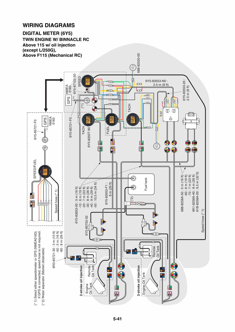
5-41
Spe
ed h
ose
(* 1
) Fue
l tan
k
OU
T
IN
OU
T
IN
(*1)
(*2)
6Y5-83553-N0 : 2.5 m (8 ft)
688-
8252
0-00
6Y5-
8572
1-F
0
6Y5-
8575
2-02
Spe
ed h
ose
(* 1
)688-
8258
A-5
0 : 5
m (
16 ft
)-6
0 : 6
m (
19 ft
)-7
0 : 7
m (
23 ft
)6K
1-82
58A
-40
: 8 m
(26
ft)
61B
-825
8A-0
0 : 9
.5 m
(32
ft)
6Y5-
8355
3-F
1 :
8 m
(26
ft)
6Y5-
8355
3-20
: 2.
5 m
(8
ft)
6Y5-
8365
3-00
: 5
m (
16 ft
)-1
0 : 6
m (
19 ft
)-2
0 : 7
m (
23 ft
)-3
0 : 8
m (
26 ft
)-4
0 : 9
m (
29 ft
)-5
0 : 1
0.5
m (
34 ft
)
GP
S
Rem
ote
Oil
Tan
k
FU
EL
TA
CH
Eng
ine
Oil
Tan
k
NM
EA
0183
SP
EE
D2-
stro
ke o
il in
ject
ion
Eng
ine
Oil
Tan
k
2-st
roke
oil
inje
ctio
n
(* 1
) S
elec
t eith
er s
peed
omet
er o
r G
PS
(N
ME
A01
83)
If
GP
S is
con
nect
ed, s
peed
hos
e is
not
req
uire
d.(*
2)
Wat
er s
epar
ator
(M
arke
t obt
aina
ble)
6R3-
8572
1-30
: 3
m (
10 ft
)-5
0 : 5
m (
16 ft
)-8
0 : 8
m (
26 ft
)
6Y5-
8712
2-S
0
GP
SN
ME
A01
83
6Y5-
8572
1-F
0
TA
CH
6Y5-
8350
T-9
0
Rem
ote
Oil
Tan
k
SP
EE
D/F
UE
L
(+)
(+)
WIRING DIAGRAMSDIGITAL METER (6Y5)TWIN ENGINE W/ BINNACLE RCAbove 115 w/ oil injection(except L/250G), Above F115 (Mechanical RC)

5-42
Rel
ay A
SS
Y6Y
5-81
950-
02
Lam
p sw
itch
Fus
e
For
pre
-mix
edm
odel
s
Tac
hom
eter
with
oil
indi
cato
rT
rim
met
er
Spe
edom
eter
Cha
rge
war
ning
uni
tW
ater
pre
ssur
em
eter
Vol
tage
met
erD
igita
l hou
r m
eter
Mec
hani
cal
hour
met
erF
uel m
eter
The
rmo
sens
orF
uel s
enso
r
Eng
ine
isru
nnin
g M
ain
switc
h is
“ON
”
Wat
er te
mpe
ratu
rem
eter
Cha
rge
lam
p
YA
MA
HA
6Y5-
8355
3-00
: 2.
5 m
(8
ft)
688-
8252
0-00
6Y5-
8355
3-10
64D
-825
53-5
0 : 5
m (
16 ft
)-7
0 : 7
m (
23 ft
)-8
0 : 8
m (
26 ft
)-9
0 : 9
m (
29 ft
)
6Y5-
8252
1-00
6Y5-
8214
9-00
6Y5-
8211
7-00
Tac
hom
eter
with
out o
il in
dica
tor
WIRING DIAGRAMSANALOG METER (6Y7)2-STROKE ENGINES250G/L250G & Premixed engines
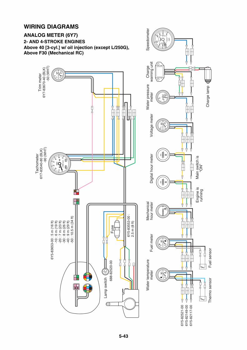
5-43
Fus
e
Trim
met
er6Y
7-83
670-
40 (
BLK
)
-5
0 (W
HT
)
Lam
p sw
itch
Spe
edom
eter
Cha
rge
war
ning
uni
tW
ater
pre
ssur
em
eter
Vol
tage
met
erD
igita
l hou
r m
eter
Mec
hani
cal
hour
met
erF
uel m
eter
The
rmo
sens
orF
uel s
enso
r
Eng
ine
isru
nnin
g M
ain
switc
h is
“ON
”
Wat
er te
mpe
ratu
rem
eter
Cha
rge
lam
p
Tac
hom
eter
6Y7-
8354
0-80
(B
LK)
-90
(WH
T)
YA
MA
HA
6Y5-
8355
3-00
: 2.
5 m
(8
ft)
6Y5-
8365
3-00
: 5
m (
16 ft
)-1
0 : 6
m (
19 ft
)-2
0 : 7
m (
23 ft
)-3
0 : 8
m (
26 ft
)-4
0 : 9
m (
29 ft
)-5
0 : 1
0.5
m (
34 ft
)
6Y5-
8252
1-00
6Y5-
8214
9-00
6Y5-
8211
7-00
688-
8252
0-00
WIRING DIAGRAMSANALOG METER (6Y7)2- AND 4-STROKE ENGINESAbove 40 [3-cyl.] w/ oil injection (except L/250G),Above F30 (Mechanical RC)
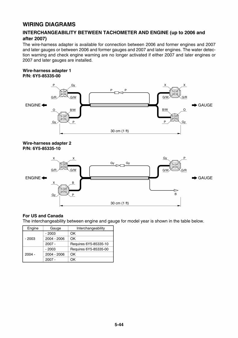
5-44
WIRING DIAGRAMSINTERCHANGEABILITY BETWEEN TACHOMETER AND ENGINE (up to 2006 and after 2007)The wire-harness adapter is available for connection between 2006 and former engines and 2007and later gauges or between 2006 and former gauges and 2007 and later engines. The water detec-tion warning and check engine warning are no longer activated if either 2007 and later engines or2007 and later gauges are installed.
Wire-harness adapter 1P/N: 6Y5-85335-00
Wire-harness adapter 2P/N: 6Y5-85335-10
For US and CanadaThe interchangeability between engine and gauge for model year is shown in the table below.
Engine Gauge Interchangeability
- 2003- 2003 OK2004 - 2006 OK
2007 - Requires 6Y5-85335-10
2004 -
- 2003 Requires 6Y5-85335-00
2004 - 2006 OK2007 - OK
PP
30 cm (1 ft)
ENGINE GAUGEB/W
P
O
Gy
X
G/R
X
G/W
Gy
G/W
P
G/R
O
Gy
B/W
P
GyGy
B
30 cm (1 ft)
ENGINE GAUGEB
P
X
Gy
P
G/R
Gy
G/W
X
G/W
X
G/R
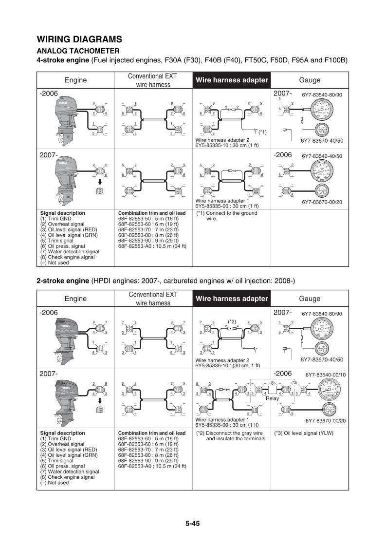
5-45
WIRING DIAGRAMSANALOG TACHOMETER4-stroke engine (Fuel injected engines, F30A (F30), F40B (F40), FT50C, F50D, F95A and F100B)
2-stroke engine (HPDI engines: 2007-, carbureted engines w/ oil injection: 2008-)
Engine Conventional EXT wire harness
Gauge
-2006
2007-
2007-
Signal description(1) Trim GND(2) Overheat signal(3) Oil level signal (RED)(4) Oil level signal (GRN)(5) Trim signal(6) Oil press. signal(7) Water detection signal(8) Check engine signal(–) Not used
Combination trim and oil lead68F-82553-50 : 5 m (16 ft)68F-82553-60 : 6 m (19 ft)68F-82553-70 : 7 m (23 ft)68F-82553-80 : 8 m (26 ft)68F-82553-90 : 9 m (29 ft)68F-82553-A0 : 10.5 m (34 ft)
6Y7-83540-80/90
6Y7-83670-40/50
Wire harness adapter 16Y5-85335-00 : 30 cm (1 ft)
Wire harness adapter 26Y5-85335-10 : 30 cm (1 ft)
-2006 6Y7-83540-40/50
6Y7-83670-00/20
(*1) Connect to the ground wire.
Wire harness adapter
1
2 6
8 –
– 5
–
6–
52
6 2
– 8
5 –
1 –
– 6
2 5
6 –
– 2
– 5
– –
– 6
2 5
– 5
– 1
5 –
1
6 2
– 8
2 6
8 –
– 6
2 5
– –
–
– –
–
6 –
5 2
6 –
5 2
– –
–
5 –
– –
– 6
2
–
2 2
1
–– –
–
1(*1)
Engine Conventional EXT
wire harnessGauge
2007- 6Y7-83540-80/90
6Y7-83670-40/50Wire harness adapter 26Y5-85335-10 : (30 cm, 1 ft)
-2006
2007-
Wire harness adapter 16Y5-85335-00 : 30 cm (1 ft)
-2006 6Y7-83540-00/10
6Y7-83670-00/20
Combination trim and oil lead68F-82553-50 : 5 m (16 ft)68F-82553-60 : 6 m (19 ft)68F-82553-70 : 7 m (23 ft)68F-82553-80 : 8 m (26 ft)68F-82553-90 : 9 m (29 ft)68F-82553-A0 : 10.5 m (34 ft)
Signal description(1) Trim GND(2) Overheat signal(3) Oil level signal (RED)(4) Oil level signal (GRN)(5) Trim signal(6) Oil press. signal(7) Water detection signal(8) Check engine signal(–) Not used
(*2) Disconnect the gray wire and insulate the terminals.
(*3) Oil level signal (YLW)
Wire harness adapter
1
4 3
8 7
2 5
–
3 –
5 2
3 4
7 8
5 2
1 –
4 3
2 5
2 5
– 1
5 2
1 –
3 4
7 8
4 3
8 7
4 3
2 5
3 4
–
– 5
– ––
4 3
2 5
– –
–
– –
– –
3 4
5 2
3 4
5 2
–
– –
–
5 –
– –
4 3
– –
2 4
1 1
(*2)
Relay3 4
– –
4 3
– (*3)
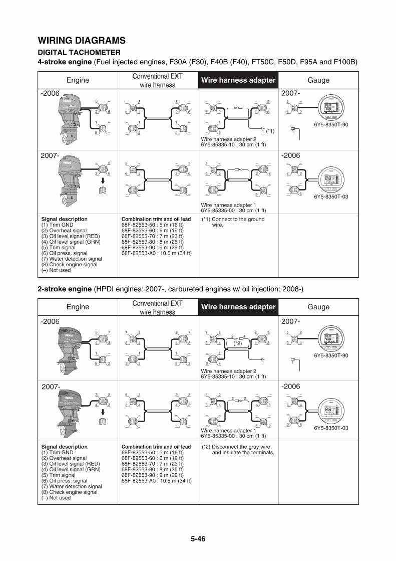
5-46
WIRING DIAGRAMSDIGITAL TACHOMETER4-stroke engine (Fuel injected engines, F30A (F30), F40B (F40), FT50C, F50D, F95A and F100B)
2-stroke engine (HPDI engines: 2007-, carbureted engines w/ oil injection: 2008-)
Engine Conventional EXT wire harness
Gauge
Signal description(1) Trim GND(2) Overheat signal(3) Oil level signal (RED)(4) Oil level signal (GRN)(5) Trim signal(6) Oil press. signal(7) Water detection signal(8) Check engine signal(–) Not used
Combination trim and oil lead68F-82553-50 : 5 m (16 ft)68F-82553-60 : 6 m (19 ft)68F-82553-70 : 7 m (23 ft)68F-82553-80 : 8 m (26 ft)68F-82553-90 : 9 m (29 ft)68F-82553-A0 : 10.5 m (34 ft)
Wire harness adapter 16Y5-85335-00 : 30 cm (1 ft)
-2006 2007-
6Y5-8350T-90
Wire harness adapter 26Y5-85335-10 : 30 cm (1 ft)
2007- -2006
6Y5-8350T-03
(*1) Connect to the ground wire.
Wire harness adapter
6 2
– –
– 5
– –
6 2
5 –
–
– –
–
5 –
– –
–
2 6
–
1
2 6
8 –
– 5
–
6 2
5 –
6 2
– –
5 –
1 –
2 6
– 5
– 5
– 1
5 –
1 –
6 2
– 8
2 6
8 –
–
2 6
– 5
– –
–
– –
– –
6 2
5 –
2 6
– 5
(*1)1 1
1
2
3
4
5
TACH
x100r/min
set mode
h
Engine Conventional EXT wire harness
Gauge
2007-
-2006 2007-
Wire harness adapter 26Y5-85335-10 : 30 cm (1 ft)
6Y5-8350T-90
Wire harness adapter 16Y5-85335-00 : 30 cm (1 ft)
-2006
6Y5-8350T-03
Signal description(1) Trim GND(2) Overheat signal(3) Oil level signal (RED)(4) Oil level signal (GRN)(5) Trim signal(6) Oil press. signal(7) Water detection signal(8) Check engine signal(–) Not used
Combination trim and oil lead68F-82553-50 : 5 m (16 ft)68F-82553-60 : 6 m (19 ft)68F-82553-70 : 7 m (23 ft)68F-82553-80 : 8 m (26 ft)68F-82553-90 : 9 m (29 ft)68F-82553-A0 : 10.5 m (34 ft)
(*2) Disconnect the gray wire and insulate the terminals.
Wire harness adapter
1
4 3
8 7
2 5
–
3 4
7 8
5 2
1 –
4 3
2 5
2 5
– 1
5 2
1 –
3 4
7 8
4 3
8 7
3 4
5 2
3 4
– –
2 5
– –
3 4
5 2
–
– –
–
5 2
– –
–
4 3
–
–
4 3
2 5
– –
–
– –
– –
3 4
5 2
4 3
2 5
(*2)2 4
1 1
2 2
1
2
3
4
5
TACH
x100r/min
set mode
h
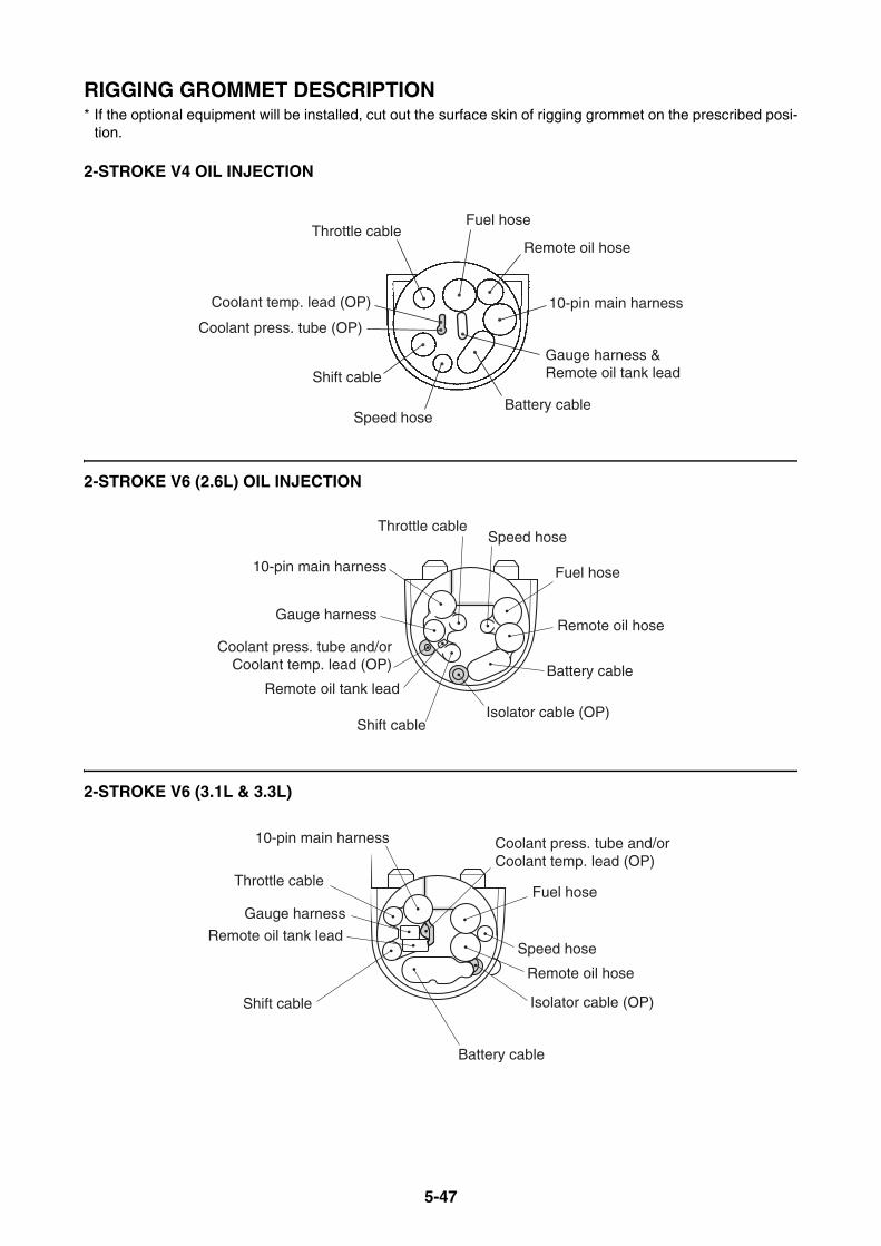
5-47
RIGGING GROMMET DESCRIPTION* If the optional equipment will be installed, cut out the surface skin of rigging grommet on the prescribed posi-
tion.
2-STROKE V4 OIL INJECTION
2-STROKE V6 (2.6L) OIL INJECTION
2-STROKE V6 (3.1L & 3.3L)
Gauge harness & Remote oil tank lead
10-pin main harness
Remote oil hose
Fuel hoseThrottle cable
Coolant press. tube (OP)
Coolant temp. lead (OP)
Shift cable
Battery cableSpeed hose
Shift cable
Throttle cable
10-pin main harness
Gauge harness
Remote oil tank leadBattery cable
Remote oil hose
Fuel hose
Speed hose
Isolator cable (OP)
Coolant press. tube and/orCoolant temp. lead (OP)
Throttle cable
Shift cable
Remote oil tank lead
Battery cable
Fuel hose
Speed hose
Isolator cable (OP)
Remote oil hose
10-pin main harness
Gauge harness
Coolant press. tube and/or Coolant temp. lead (OP)
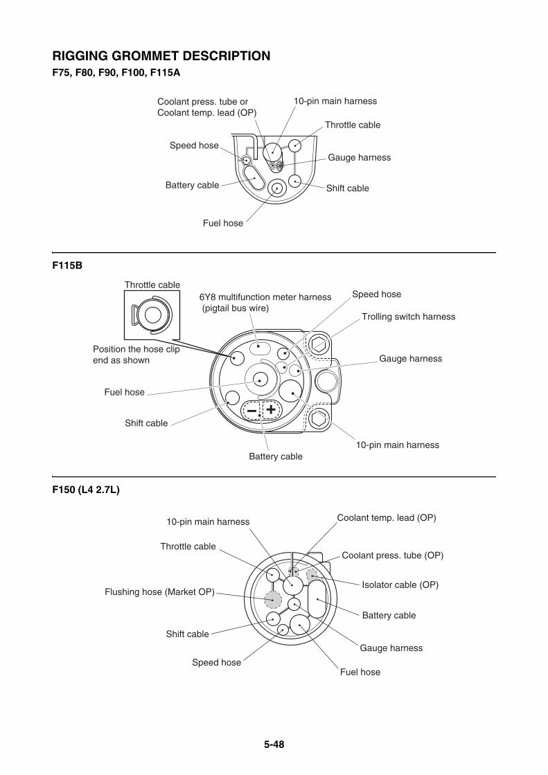
5-48
RIGGING GROMMET DESCRIPTIONF75, F80, F90, F100, F115A
F115B
F150 (L4 2.7L)
Throttle cable
Shift cable
Gauge harness
10-pin main harness
Speed hose
Battery cable
Fuel hose
Coolant press. tube or Coolant temp. lead (OP)
Trolling switch harness
6Y8 multifunction meter harness (pigtail bus wire)
Position the hose clip end as shown
Fuel hose
Throttle cable
10-pin main harness
Shift cable
Speed hose
Gauge harness
Battery cable
Throttle cable
10-pin main harness
Coolant press. tube (OP)
Coolant temp. lead (OP)
Isolator cable (OP)
Battery cable
Gauge harness
Flushing hose (Market OP)
Shift cable
Speed hoseFuel hose

5-49
RIGGING GROMMET DESCRIPTIONF200, F225, F250 (V6-3.3L) w/ Variable Camshaft Timing[Mechanical RC]
F200, F225, F250, F275 VMAX (SHO) and F150, F165, F175, F200(L4-2.8L)
F200 (L4-2.8L), F225, F250, F300 (V6-4.2L) [DEC]
Fuel hose
Gauge harness
Battery cable
Isolator cable (OP) Throttle cable
Flushing hose (Market OP)
Shift cable
Speed hose
10-pin main harness
Coolant temp. lead and/or Coolant press. tube (OP)
Flushing hose (market OP)
Position the hose clip end as shown
M6 bolt: 8 Nm, 0.8 kgf·m, 13 ft·lb
Fuel hoseThrottle cable
10-pin main wire-harness
Coolant temp. wire/ pressure tube (OP)(for conventional gauge)
Shift cable
Speed hose
Gauge wire-harness or Pigtail bus wire
Battery cable
Flushing hose (market OP)
Position the hose clip end as shown
M6 bolt: 8 Nm, 0.8 kgf·m, 13 ft·lbFuel hose
16-pin main wire-harness
Isolator cable (OP)
Speed hose
Battery cable
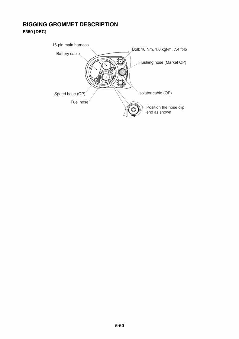
5-50
RIGGING GROMMET DESCRIPTIONF350 [DEC]
16-pin main harness
Flushing hose (Market OP)
Isolator cable (OP)
Fuel hose
Speed hose (OP)
Battery cableBolt: 10 Nm, 1.0 kgf·m, 7.4 ft·lb
Position the hose clip end as shown
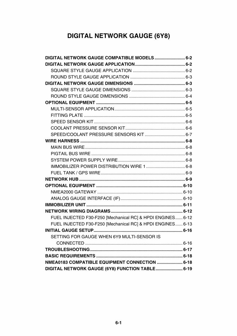
6-1
DIGITAL NETWORK GAUGE (6Y8)
DIGITAL NETWORK GAUGE COMPATIBLE MODELS ......................... 6-2DIGITAL NETWORK GAUGE APPLICATION......................................... 6-2
SQUARE STYLE GAUGE APPLICATION ........................................... 6-2
ROUND STYLE GAUGE APPLICATION ............................................. 6-3
DIGITAL NETWORK GAUGE DIMENSIONS .......................................... 6-3SQUARE STYLE GAUGE DIMENSIONS ............................................ 6-3
ROUND STYLE GAUGE DIMENSIONS .............................................. 6-4
OPTIONAL EQUIPMENT ......................................................................... 6-5MULTI-SENSOR APPLICATION.......................................................... 6-5
FITTING PLATE ................................................................................... 6-5
SPEED SENSOR KIT........................................................................... 6-6
COOLANT PRESSURE SENSOR KIT................................................. 6-6
SPEED/COOLANT PRESSURE SENSORS KIT ................................. 6-7
WIRE HARNESS ...................................................................................... 6-8MAIN BUS WIRE.................................................................................. 6-8
PIGTAIL BUS WIRE ............................................................................. 6-8
SYSTEM POWER SUPPLY WIRE....................................................... 6-8
IMMOBILIZER POWER DISTRIBUTION WIRE 1 ................................ 6-8
FUEL TANK / GPS WIRE..................................................................... 6-9
NETWORK HUB ....................................................................................... 6-9OPTIONAL EQUIPMENT ....................................................................... 6-10
NMEA2000 GATEWAY ...................................................................... 6-10
ANALOG GAUGE INTERFACE (IF)................................................... 6-10
IMMOBILIZER UNIT ............................................................................... 6-11NETWORK WIRING DIAGRAMS........................................................... 6-12
FUEL INJECTED F30-F250 [Mechanical RC] & HPDI ENGINES...... 6-12
FUEL INJECTED F30-F250 [Mechanical RC] & HPDI ENGINES...... 6-13
INITIAL GAUGE SETUP......................................................................... 6-16SETTING FOR GAUGE WHEN 6Y9 MULTI-SENSOR IS
CONNECTED ................................................................................ 6-16
TROUBLESHOOTING............................................................................ 6-17BASIC REQUIREMENTS ....................................................................... 6-18NMEA0183 COMPATIBLE EQUIPMENT CONNECTION ..................... 6-18DIGITAL NETWORK GAUGE (6Y8) FUNCTION TABLE...................... 6-19
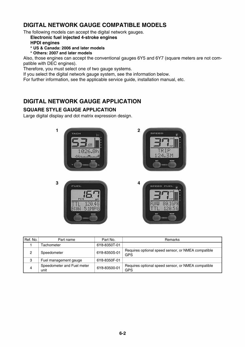
6-2
DIGITAL NETWORK GAUGE COMPATIBLE MODELSThe following models can accept the digital network gauges.
Electronic fuel injected 4-stroke enginesHPDI engines* US & Canada: 2006 and later models* Others: 2007 and later models
Also, those engines can accept the conventional gauges 6Y5 and 6Y7 (square meters are not com-patible with DEC engines).Therefore, you must select one of two gauge systems.If you select the digital network gauge system, see the information below.For further information, see the applicable service guide, installation manual, etc.
DIGITAL NETWORK GAUGE APPLICATIONSQUARE STYLE GAUGE APPLICATIONLarge digital display and dot matrix expression design.
Ref. No. Part name Part No. Remarks
1 Tachometer 6Y8-8350T-01
2 Speedometer 6Y8-8350S-01Requires optional speed sensor, or NMEA compatible GPS
3 Fuel management gauge 6Y8-8350F-01
4Speedometer and Fuel meter unit
6Y8-83500-01Requires optional speed sensor, or NMEA compatible GPS
1 2
3 4
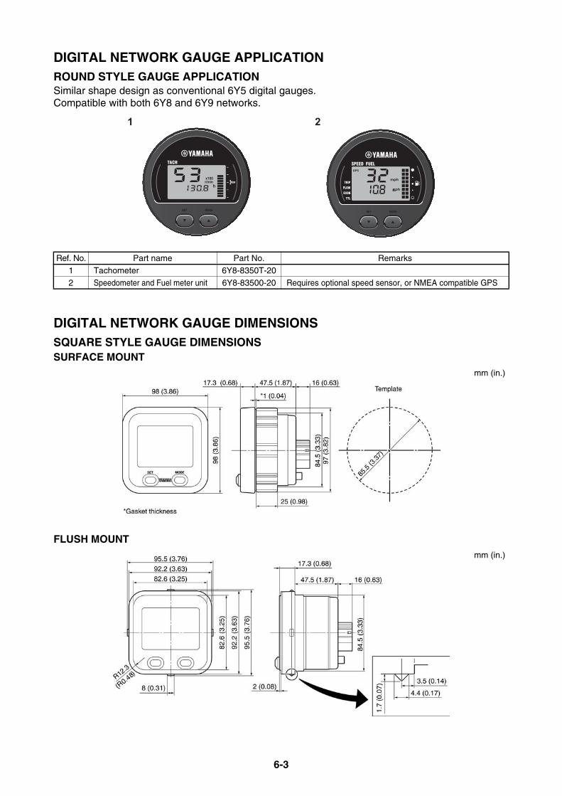
6-3
DIGITAL NETWORK GAUGE APPLICATIONROUND STYLE GAUGE APPLICATIONSimilar shape design as conventional 6Y5 digital gauges.Compatible with both 6Y8 and 6Y9 networks.
DIGITAL NETWORK GAUGE DIMENSIONSSQUARE STYLE GAUGE DIMENSIONSSURFACE MOUNT
FLUSH MOUNT
Ref. No. Part name Part No. Remarks
1 Tachometer 6Y8-8350T-20
2 Speedometer and Fuel meter unit 6Y8-83500-20 Requires optional speed sensor, or NMEA compatible GPS
1 2
mm (in.)
mm (in.)
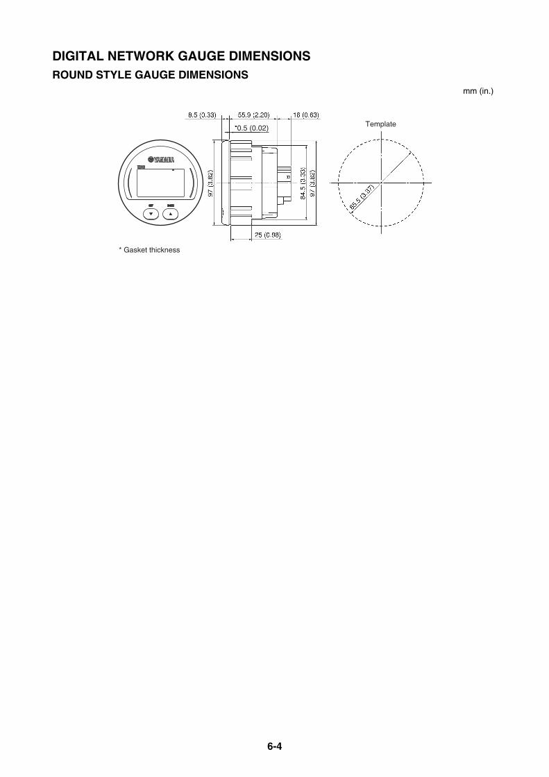
6-4
DIGITAL NETWORK GAUGE DIMENSIONSROUND STYLE GAUGE DIMENSIONS
* Gasket thickness
Template0.5 (0.02)
mm (in.)
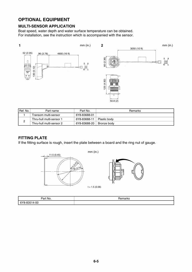
6-5
OPTIONAL EQUIPMENTMULTI-SENSOR APPLICATIONBoat speed, water depth and water surface temperature can be obtained.For installation, see the instruction which is accompanied with the sensor.
FITTING PLATEIf the fitting surface is rough, insert the plate between a board and the ring nut of gauge.
Ref. No. Part name Part No. Remarks
1 Transom multi-sensor 6Y8-83688-01
2Thru-hull multi-sensor 1 6Y8-83688-11 Plastic body
Thru-hull multi-sensor 2 6Y8-83688-20 Bronze body
Part No. Remarks6Y8-83514-00
96 (3.78)
130
(5.1
2)
4900 (16 ft)52 (2.05)
BR
LW
50.8 (2)
125
(4.9
2)
3050 (10 ft)
BR
LW
60 (
2.36
)
1 2 mm (in.)mm (in.)
95 (3.74)
t = 1.5 (0.06)
85.5
(3.37
)
11.5 (0.45)mm (in.)
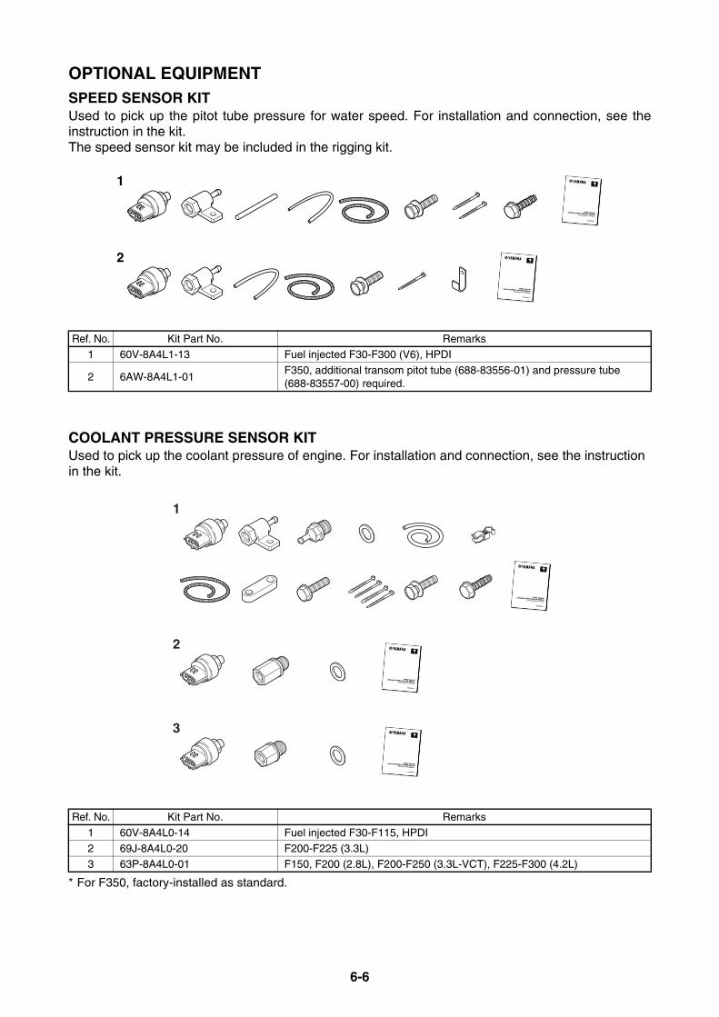
6-6
OPTIONAL EQUIPMENTSPEED SENSOR KITUsed to pick up the pitot tube pressure for water speed. For installation and connection, see theinstruction in the kit.The speed sensor kit may be included in the rigging kit.
COOLANT PRESSURE SENSOR KITUsed to pick up the coolant pressure of engine. For installation and connection, see the instructionin the kit.
* For F350, factory-installed as standard.
Ref. No. Kit Part No. Remarks1 60V-8A4L1-13 Fuel injected F30-F300 (V6), HPDI
2 6AW-8A4L1-01F350, additional transom pitot tube (688-83556-01) and pressure tube (688-83557-00) required.
Ref. No. Kit Part No. Remarks
1 60V-8A4L0-14 Fuel injected F30-F115, HPDI
2 69J-8A4L0-20 F200-F225 (3.3L)3 63P-8A4L0-01 F150, F200 (2.8L), F200-F250 (3.3L-VCT), F225-F300 (4.2L)
1
2
1
2
3

6-7
OPTIONAL EQUIPMENTSPEED/COOLANT PRESSURE SENSORS KIT
Ref. No. Kit Part No. Remarks1 60V-8A4L2-02 F115A, F115B
1
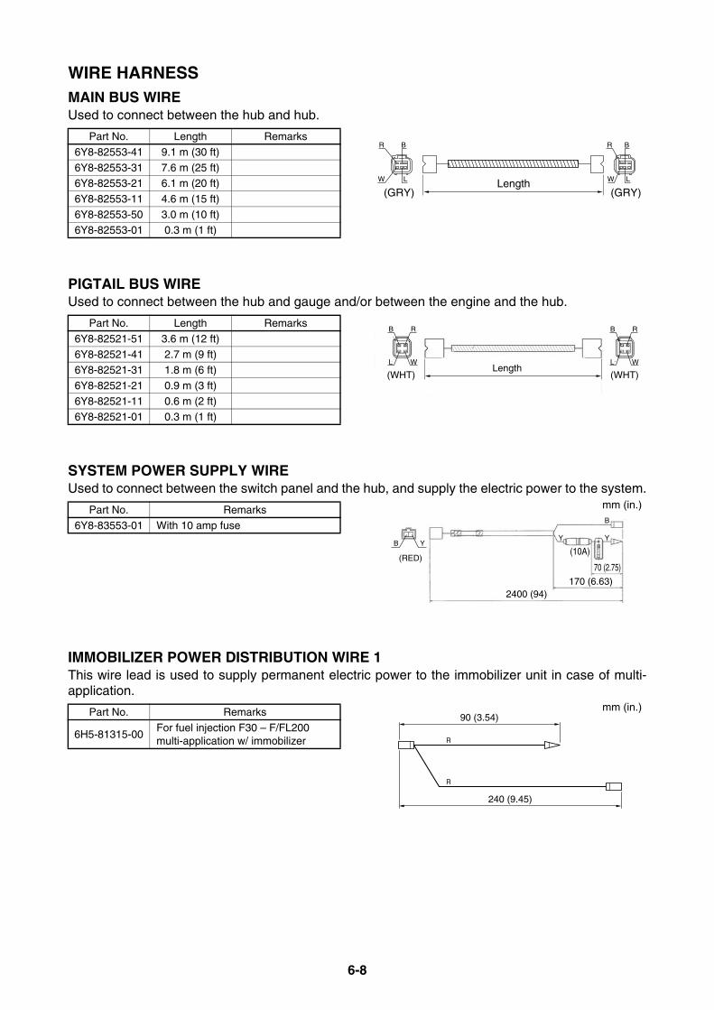
6-8
WIRE HARNESSMAIN BUS WIREUsed to connect between the hub and hub.
PIGTAIL BUS WIREUsed to connect between the hub and gauge and/or between the engine and the hub.
SYSTEM POWER SUPPLY WIREUsed to connect between the switch panel and the hub, and supply the electric power to the system.
IMMOBILIZER POWER DISTRIBUTION WIRE 1This wire lead is used to supply permanent electric power to the immobilizer unit in case of multi-application.
Part No. Length Remarks
6Y8-82553-41 9.1 m (30 ft)
6Y8-82553-31 7.6 m (25 ft)6Y8-82553-21 6.1 m (20 ft)
6Y8-82553-11 4.6 m (15 ft)
6Y8-82553-50 3.0 m (10 ft)6Y8-82553-01 0.3 m (1 ft)
Part No. Length Remarks
6Y8-82521-51 3.6 m (12 ft)
6Y8-82521-41 2.7 m (9 ft)6Y8-82521-31 1.8 m (6 ft)
6Y8-82521-21 0.9 m (3 ft)
6Y8-82521-11 0.6 m (2 ft)6Y8-82521-01 0.3 m (1 ft)
Part No. Remarks
6Y8-83553-01 With 10 amp fuse
Part No. Remarks
6H5-81315-00For fuel injection F30 – F/FL200 multi-application w/ immobilizer
Length(GRY) (GRY)
R B
W
R B
W LL
Length
B R
WL
B R
WL
(WHT) (WHT)
2400 (94)
70 (2.75)
170 (6.63)
(10A)B
(RED)
Y
B
YY
mm (in.)
R
R
90 (3.54)
240 (9.45)
mm (in.)

6-9
WIRE HARNESSFUEL TANK / GPS WIREUsed to connect between a fuel tank level sensor and/or an MNEA0183 compatible GPS and thespeedometer (with fuel mgt gauge).
NETWORK HUBUsed to distribute the digital signal and electric power to the gauges and the other hubs.
Part No. Remarks
6Y8-8356N-01 Twin fuel tanks acceptable
Ref. No. Part name Part No. Remarks
1 Multi-hub 6Y8-81920-01 With ending resistor cap (P/N: 6Y8-85371-01)2 Single hub (Inline hub) 6Y8-81920-11 Included ending resistor
3 2-pin sealing cap, RED 6Y8-82582-01
4 4-pin sealing cap, WHT 6Y8-82582-11 Same as bus wire cap of engine wire harness
300 (11.8)
220 (8.66)
GPS
B
BLW
PP/B
P/BB
W
Fueltank
L(+)(GND)
(BLK)
P
B
mm (in.)
178 (7.01)
Resistor cap (GRY)
194.8 (7.67)
7 (0.28)
41.4
(1.6
3)21
.4 (
0.84
)
10(0
.39)
22.5
5(0
.88)
19.65(0.77) 42 (1.65)
(WHT)
26 (1.02)18.54 (0.73)
19.3
(0.
76)
(RED)
23.95 (0.94)
20.2
5 (0
.79)
26 (1.02)
(WHT)
1 2
3
4
mm (in.)mm (in.)
* Face the connectors downward for installation.

6-10
OPTIONAL EQUIPMENTNMEA2000 GATEWAYUsed to connect between NMEA2000 compatible equipment and network hub.
ANALOG GAUGE INTERFACE (IF)Used to connect between analog gauge and network hub.
Part No. Remarks
6Y9-8A2D0-20 Compatible with 6Y8 and 6Y9 protocols
Part No. Remarks6Y9-8A2D0-30 Compatible with 6Y8 and 6Y9 protocols, Required for each engine.
5.5(0.22)
20.5(0.81)116 (4.57)
130 (5.12)
To NMEA2000equipment
To network hubvia wire-lead6Y9-83553-50
12 (
0.47
)
1.8 (0.07)
4.8 (0.19)
56 (
2.20
)
7.8 (0.31)
500 (19.7)
20
YELLOW
mm (in.)
1.8
(0.0
7)
4.6
(0.1
8)
7.8 (0.31)
To wire-harness6Y5-83553-00
To analog tachometer via trim/oil lead6Y5-83653-*0
To hubvia wire-lead6Y9-83553-50
12 (0.4
7)
16 (
0.63
)
116 (4.57)
130 (5.12)
400 (15.8)
Engine selection for analog tachometer:
56 (
2.20
)
5.5 (0.22)
20.5(0.81)
BOrBLBOrBL BOrBLBOrBL
— —
— —
—CENTER engine
CENTER PORT engine CENTER STBD engine STBD enginePORT engine
PORT engine
PORT engine
PORT engine
Quad engine
Single engine
Twin engine
Triple engine
—
STBD engine
STBD engine
30
mm (in.)
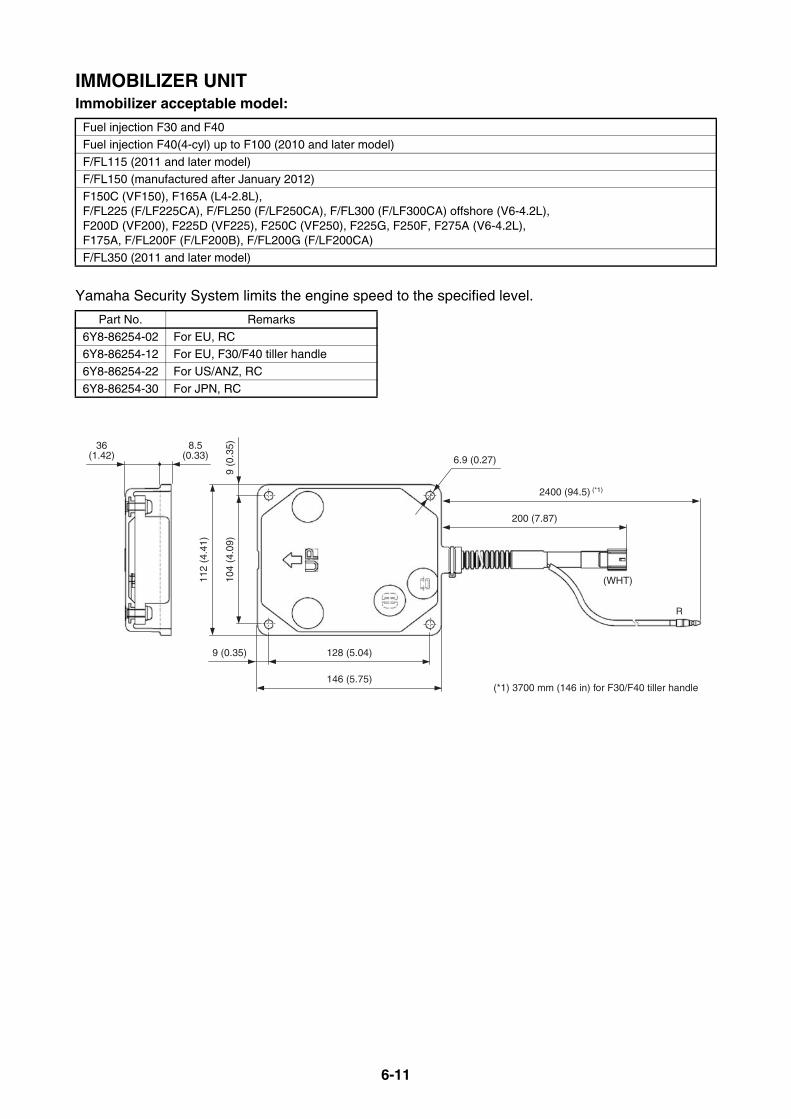
6-11
IMMOBILIZER UNITImmobilizer acceptable model:
Yamaha Security System limits the engine speed to the specified level.
Fuel injection F30 and F40
Fuel injection F40(4-cyl) up to F100 (2010 and later model)
F/FL115 (2011 and later model)F/FL150 (manufactured after January 2012)
F150C (VF150), F165A (L4-2.8L), F/FL225 (F/LF225CA), F/FL250 (F/LF250CA), F/FL300 (F/LF300CA) offshore (V6-4.2L), F200D (VF200), F225D (VF225), F250C (VF250), F225G, F250F, F275A (V6-4.2L), F175A, F/FL200F (F/LF200B), F/FL200G (F/LF200CA)
F/FL350 (2011 and later model)
Part No. Remarks
6Y8-86254-02 For EU, RC6Y8-86254-12 For EU, F30/F40 tiller handle
6Y8-86254-22 For US/ANZ, RC
6Y8-86254-30 For JPN, RC
2400 (94.5) (*1)
200 (7.87)
(WHT)104
(4.0
9)9
(0.3
5)
112
(4.4
1)
128 (5.04)9 (0.35)
146 (5.75)(*1) 3700 mm (146 in) for F30/F40 tiller handle
6.9 (0.27)
8.5(0.33)
36(1.42)
R
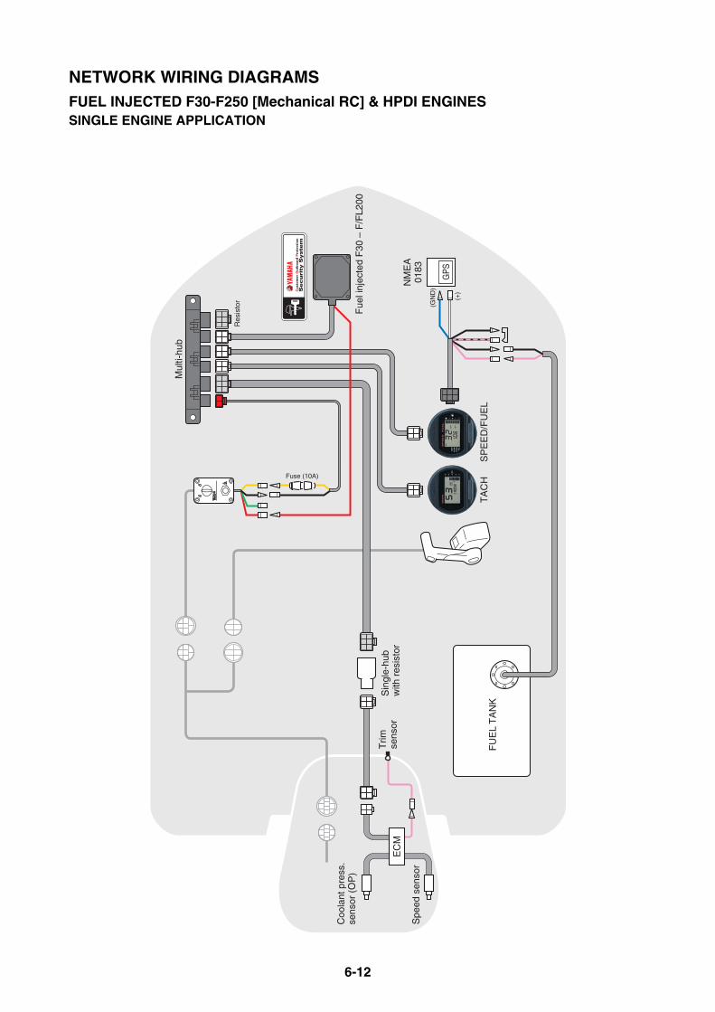
6-12
Coo
lant
pre
ss.
sens
or (
OP
)
FU
EL
TA
NK
Sin
gle-
hub
with
res
isto
rT
rimse
nsor
NM
EA
0183
Fue
l inj
ecte
d F
30 –
F/F
L200
Fuse (10A)
(+)
(GN
D)
GPS
SP
EE
D/F
UE
LT
AC
H
Spe
ed s
enso
r
EC
M
Mul
ti-hu
b
Res
isto
r
NETWORK WIRING DIAGRAMSFUEL INJECTED F30-F250 [Mechanical RC] & HPDI ENGINESSINGLE ENGINE APPLICATION
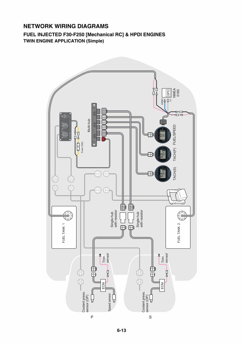
6-13
(+)
(GN
D)
P S
EC
M
EC
M
NM
EA
0183
GPS
Mul
ti-hu
b
Fuse
(10A
)
TAC
H(S
)TA
CH
(P)
FU
EL/
SP
EE
D
FUE
L TA
NK
1
FUE
L TA
NK
2
Trim
sens
or
Trim
sens
or
Coo
lant
pre
ss.
sens
or (O
P)
Coo
lant
pre
ss.
sens
or (O
P)
Spee
d se
nsor
Sin
gle-
hub
with
resi
stor
Sin
gle-
hub
with
resi
stor
NETWORK WIRING DIAGRAMSFUEL INJECTED F30-F250 [Mechanical RC] & HPDI ENGINESTWIN ENGINE APPLICATION (Simple)
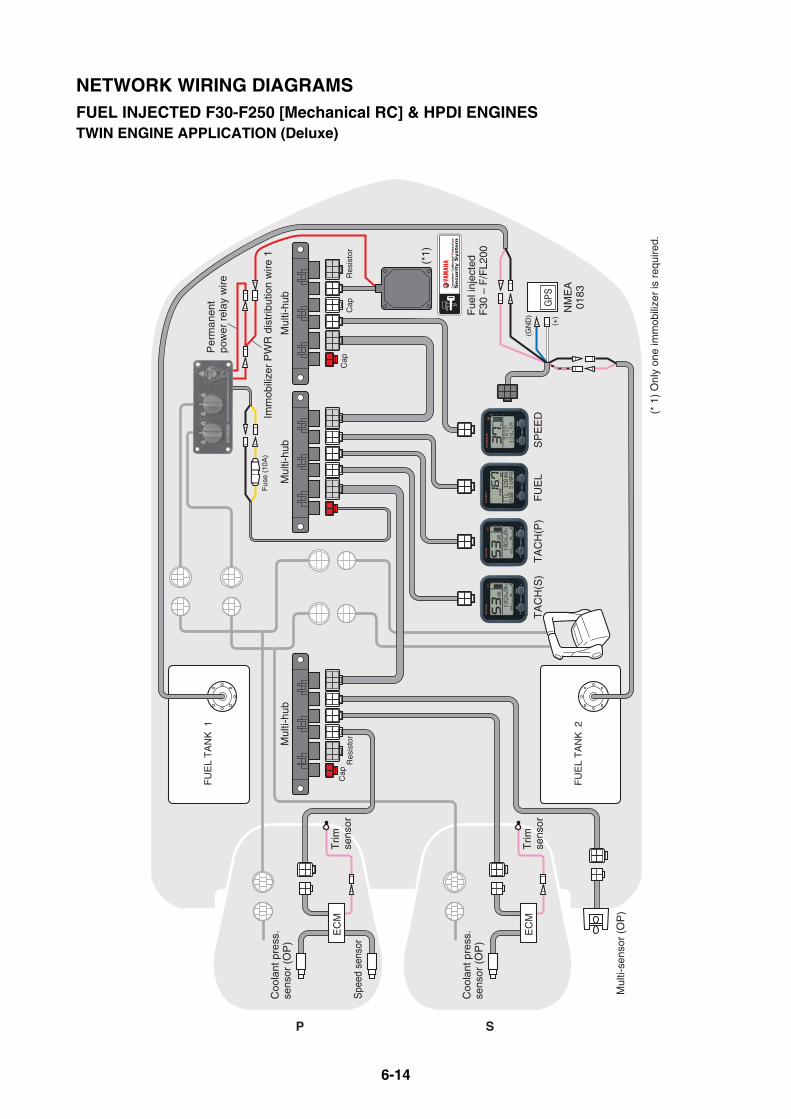
6-14
Mul
ti-se
nsor
(O
P)
FU
EL
TA
NK
2
FU
EL
TA
NK
1
(+)
(GN
D)
SP
EE
DF
UE
LT
AC
H(P
)T
AC
H(S
)
P S
Coo
lant
pre
ss.
sens
or (
OP
)
Spe
ed s
enso
r
EC
MT
rimse
nsor
Coo
lant
pre
ss.
sens
or (
OP
)
EC
MT
rimse
nsor
Fus
e (1
0A)
NM
EA
0183
GPS
Fue
l inj
ecte
dF
30 –
F/F
L200
Imm
obili
zer
PW
R d
istr
ibut
ion
wire
1
Per
man
ent
pow
er r
elay
wire
Res
isto
rR
esis
tor
Cap
Cap
Cap
Mul
ti-hu
bM
ulti-
hub
Mul
ti-hu
b
(* 1
) O
nly
one
imm
obili
zer
is r
equi
red.
(*1)
NETWORK WIRING DIAGRAMSFUEL INJECTED F30-F250 [Mechanical RC] & HPDI ENGINESTWIN ENGINE APPLICATION (Deluxe)
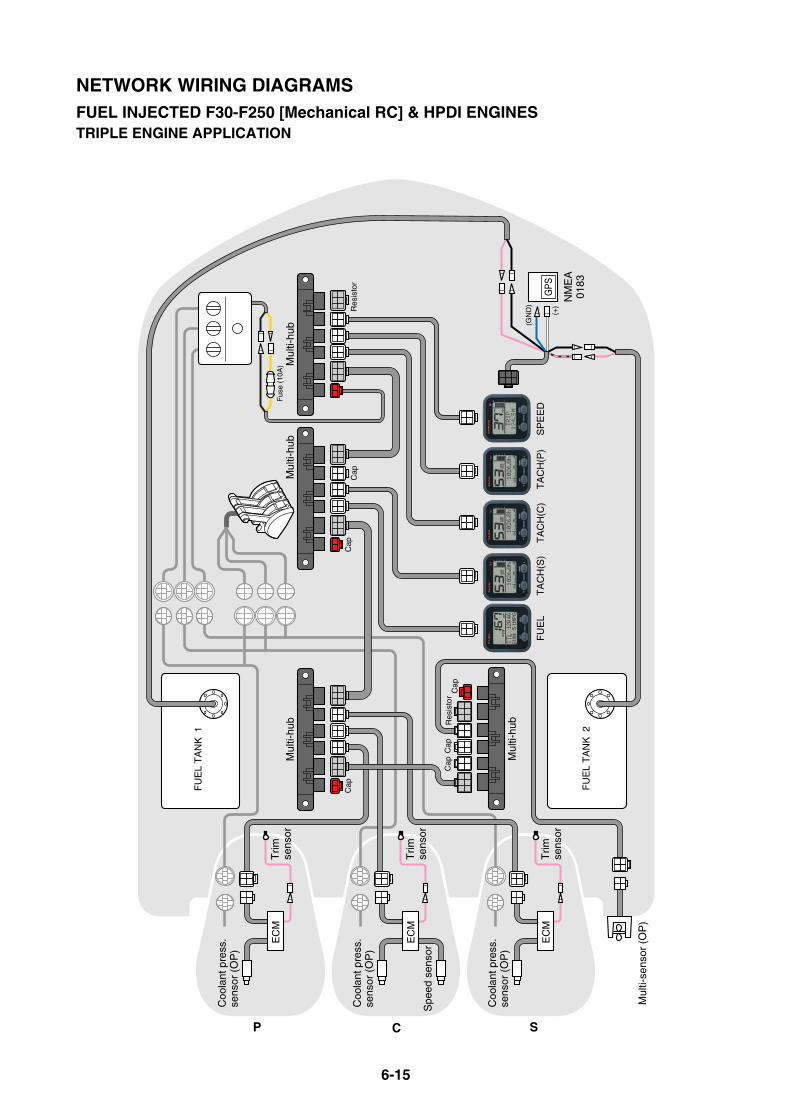
6-15
P
Mul
ti-se
nsor
(O
P)
Spe
ed s
enso
r
FU
EL
TA
NK
2
FU
EL
TA
NK
1
FU
EL
TA
CH
(C)
TA
CH
(S)
TA
CH
(P)
SP
EE
D
Coo
lant
pre
ss.
sens
or (
OP
)
EC
MT
rimse
nsor
Coo
lant
pre
ss.
sens
or (
OP
)
EC
MT
rimse
nsor
C S
Coo
lant
pre
ss.
sens
or (
OP
)
EC
MT
rimse
nsor
Fus
e (1
0A)
(+)
(GN
D)
NM
EA
0183
GPS
Mul
ti-hu
bM
ulti-
hub
Mul
ti-hu
b
Mul
ti-hu
bRes
isto
r
Cap
Cap
Cap
Cap
Res
isto
rC
apC
ap
NETWORK WIRING DIAGRAMSFUEL INJECTED F30-F250 [Mechanical RC] & HPDI ENGINESTRIPLE ENGINE APPLICATION

6-16
INITIAL GAUGE SETUPIf two or more engines with digital network gauges are installed, the initial setup is required forproper gauge operation.The ignition switches have to be turned to ON in order from Port to Starboard in 2 seconds or moreinterval, which can memorize the engine number into each ECM by a rule.The 1st turned on ignition switch is memorized as No.1 engine.The 2nd turned on is memorized as No.2 engine.This can obtain easier engine number recognition for gauge setup.When the initial recognition setup has been stumbled, reset the engine number and perform it againwith the tachometer.For further information, see the installation manual in the rigging kit.For DEC engines, the Digital Electronic Control system recognizes the engine number automati-cally, therefore the key switch ON in number order is not required.
SETTING FOR GAUGE WHEN 6Y9 MULTI-SENSOR IS CONNECTED If the 6Y9 multi-sensor (6Y9-83688-00) is connected to the conventional 6Y8 multifunction speed(speed/fuel) meters (6Y8-8350*-01 or 11), set the gauge as shown below to enable the sensor.
1. Press and hold the [SET] button for 10 seconds on the normal display. The mode "01" screen willappear.
2. Press the [MODE] button to select the mode "02".
3. Press the [SET] button for 1 second to finalize the setting and return to the normal display.
TIP:If no button operation is made for 30 seconds while setting, the setting will be automatically can-celled and return to the normal display.
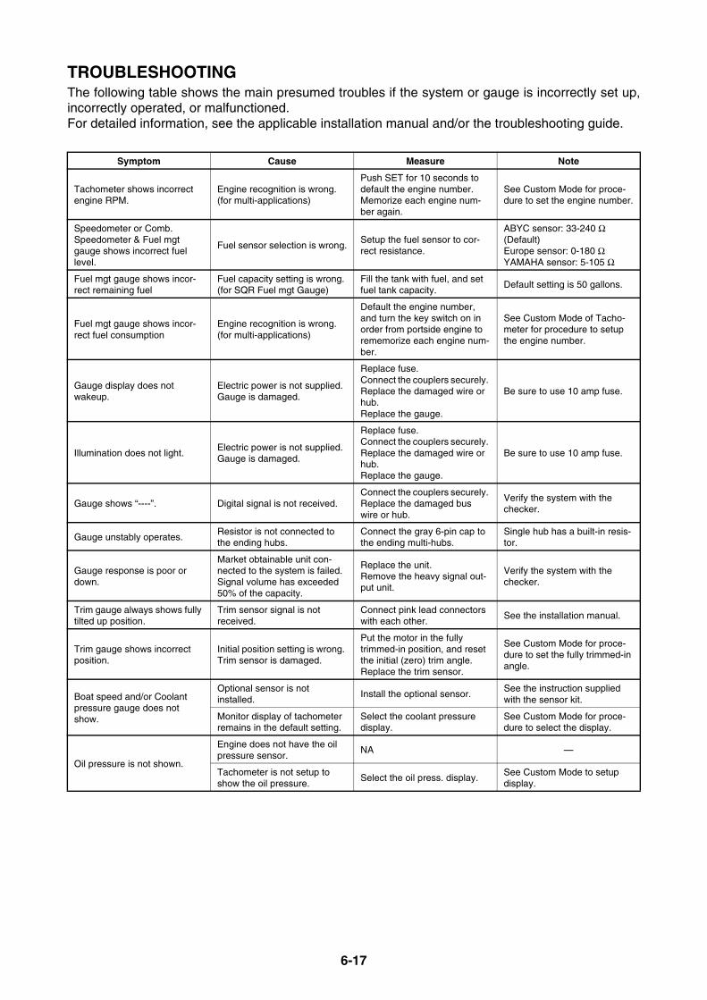
6-17
TROUBLESHOOTINGThe following table shows the main presumed troubles if the system or gauge is incorrectly set up,incorrectly operated, or malfunctioned.For detailed information, see the applicable installation manual and/or the troubleshooting guide.
Symptom Cause Measure Note
Tachometer shows incorrect engine RPM.
Engine recognition is wrong. (for multi-applications)
Push SET for 10 seconds to default the engine number. Memorize each engine num-ber again.
See Custom Mode for proce-dure to set the engine number.
Speedometer or Comb. Speedometer & Fuel mgt gauge shows incorrect fuel level.
Fuel sensor selection is wrong.Setup the fuel sensor to cor-rect resistance.
ABYC sensor: 33-240 Ω (Default) Europe sensor: 0-180 ΩYAMAHA sensor: 5-105 Ω
Fuel mgt gauge shows incor-rect remaining fuel
Fuel capacity setting is wrong. (for SQR Fuel mgt Gauge)
Fill the tank with fuel, and set fuel tank capacity.
Default setting is 50 gallons.
Fuel mgt gauge shows incor-rect fuel consumption
Engine recognition is wrong. (for multi-applications)
Default the engine number, and turn the key switch on in order from portside engine to rememorize each engine num-ber.
See Custom Mode of Tacho-meter for procedure to setup the engine number.
Gauge display does not wakeup.
Electric power is not supplied. Gauge is damaged.
Replace fuse.Connect the couplers securely. Replace the damaged wire or hub.Replace the gauge.
Be sure to use 10 amp fuse.
Illumination does not light.Electric power is not supplied. Gauge is damaged.
Replace fuse.Connect the couplers securely. Replace the damaged wire or hub.Replace the gauge.
Be sure to use 10 amp fuse.
Gauge shows “----”. Digital signal is not received.Connect the couplers securely. Replace the damaged bus wire or hub.
Verify the system with the checker.
Gauge unstably operates.Resistor is not connected to the ending hubs.
Connect the gray 6-pin cap to the ending multi-hubs.
Single hub has a built-in resis-tor.
Gauge response is poor or down.
Market obtainable unit con-nected to the system is failed. Signal volume has exceeded 50% of the capacity.
Replace the unit. Remove the heavy signal out-put unit.
Verify the system with the checker.
Trim gauge always shows fully tilted up position.
Trim sensor signal is not received.
Connect pink lead connectors with each other.
See the installation manual.
Trim gauge shows incorrect position.
Initial position setting is wrong. Trim sensor is damaged.
Put the motor in the fully trimmed-in position, and reset the initial (zero) trim angle. Replace the trim sensor.
See Custom Mode for proce-dure to set the fully trimmed-in angle.
Boat speed and/or Coolant pressure gauge does not show.
Optional sensor is not installed.
Install the optional sensor.See the instruction supplied with the sensor kit.
Monitor display of tachometer remains in the default setting.
Select the coolant pressure display.
See Custom Mode for proce-dure to select the display.
Oil pressure is not shown.
Engine does not have the oil pressure sensor.
NA —
Tachometer is not setup to show the oil pressure.
Select the oil press. display.See Custom Mode to setup display.

6-18
BASIC REQUIREMENTSThe following basic conditions are required to install the digital network gauge system onto a boat.
NMEA0183 COMPATIBLE EQUIPMENT CONNECTIONThe digital network gauge system accepts the signal of NMEA0183 version 2.0, 2.1, or 3.01 with fol-lowing sentences.
* If the signal sentence is not shown on an electric unit or its instruction, contact the manufacturer.
Item Conditions Symptom Note
Total amount quantity of unit for connecting to the system
50 units or less (Including mar-ket obtainable units, exclusive gauges and engine ECMs).
Gauge display is unstable. Gauge response is poor.
Check the system with the optional checker. Verify the conditions of sys-tem.
Total amount length of the main bus wires.
50 meter (164 feet) or less
Acceptable volume of digital communication signals
50% or less of overall signal capacity
Bus wires distance from elec-trical noise equipments (Antenna cable, Generator, Radio, etc.)
30 cm (1 ft) and more
Temperature for performing bus wires and hubs
80°C (176°F) or less
Data Sentence
Speed and Time RMC
Water depth DBT
Water surface temp. MTW

6-19
DIGITAL NETWORK GAUGE (6Y8) FUNCTION TABLE
Global model US/CA modelEngine trouble
indicatorWater detection
indicatorCooling-water pres-sure sensor (OP)
Speed sensor (OP) *For R/H model
Low oil pressure indicator
*For 4-stroke
Low oil level indicator
*For 2-stroke
Variable trolling RPM (r/min)
F30B F30A YES YES YES YES YES (switch) NA 650-900
F40D, F40H YES YES YES YES YES (switch) NA 600-900
F40F F40A YES YES YES YES YES (switch) NA 650-900
F40G YES YES YES YES YES (switch) NA 600-900
F50F, F50H F50A, F50B YES YES YES YES YES (switch) NA 600-900
FT50G, FT50J T50A, T50B YES YES YES YES YES (switch) NA 600-900
F60C, F60F F60A, F60B YES YES YES YES YES (switch) NA 600-900
FT60D, FT60G T60A, T60B YES YES YES YES YES (switch) NA 600-900
F70A F70A YES YES YES YES YES (switch) NA 600-900
F75B F75A YES YES YES YES YES (switch) NA 550-1000
F80B YES YES YES YES YES (switch) NA 550-1000
F90B F90A YES YES YES YES YES (switch) NA 550-1000
F100D YES YES YES YES YES (switch) NA 550-1000
F/FL115A F/LF115A YES YES YES YES YES (switch) NA NA
F/FL115B F/LF115B YES YES YES YES YES (switch) NA 600-1000
F/FL150A F/LF150A YES YES YES YES YES (sensor) NA NA
F/FL150B YES YES YES YES YES (sensor) NA NA
F150C VF150A YES YES YES YES YES (sensor) NA 650-900
F165A YES YES YES YES YES (sensor) NA 650-900
F/FL200B YES YES YES YES YES (sensor) NA NA
F/FL200C F/LF200A YES YES YES YES YES (sensor) NA NA
F/FL200F F/LF200B YES YES YES YES YES (sensor) NA 650-900
F/FL200G F/LF200CA YES YES YES YES YES (sensor) NA 650-900
F200D VF200A YES YES YES YES YES (sensor) NA NA
F/FL225B F/LF225A YES YES YES YES YES (sensor) NA NA
F/FL225F F/LF225CA YES YES YES YES YES (sensor) NA 600-1000
F225C YES YES YES YES YES (sensor) NA NA
F225D VF225A YES YES YES YES YES (sensor) NA NA
F/FL250A F/LF250A YES YES YES YES YES (sensor) NA NA
F/FL250D F/LF250CA YES YES YES YES YES (sensor) NA 600-1000
F/FL250G YES YES YES YES YES (sensor) NA NA
F250C VF250A YES YES YES YES YES (sensor) NA NA
F/FL300A YES YES YES YES (transom pitot tube) YES (sensor) NA 600-1000
F/FL300B F/LF300CA YES YES YES YES YES (sensor) NA 600-1000
F/FL350A F/LF350CB YES YES YES (STD) YES (transom pitot tube) YES (sensor) NA 600-1000
Z150Q VZ150TR YES YES YES YES NA YES NA

7-1
DIGITAL NETWORK PREMIUM GAUGE (6Y9)
DIGITAL NETWORK PREMIUM GAUGE COMPATIBLE MODELS ....... 7-3DIGITAL NETWORK PREMIUM GAUGE APPLICATION....................... 7-3DIGITAL NETWORK PREMIUM GAUGE DIMENSIONS ........................ 7-4
PREMIUM COLOR GAUGE DIMENSIONS ......................................... 7-4
OPTIONAL EQUIPMENT ......................................................................... 7-5TRANSOM MULTI-SENSOR (6Y9)...................................................... 7-5
IMMOBILIZER UNIT ............................................................................. 7-5
NMEA2000 GATEWAY ........................................................................ 7-6
ANALOG GAUGE INTERFACE (IF)..................................................... 7-6
SPEED SENSOR KIT........................................................................... 7-7
COOLANT PRESSURE SENSOR KIT................................................. 7-7
NETWORK HUB ....................................................................................... 7-8WIRE HARNESS ...................................................................................... 7-9
MAIN BUS WIRE.................................................................................. 7-9
PIGTAIL BUS WIRE ............................................................................. 7-9
GPS WIRE............................................................................................ 7-9
TANK WIRE.......................................................................................... 7-9
SYSTEM POWER SUPPLY WIRE..................................................... 7-10
SYSTEM POWER DISTRIBUTION WIRE.......................................... 7-10
IMMOBILIZER POWER DISTRIBUTION WIRE 2 .............................. 7-10
CONVERSION HARNESS ................................................................. 7-11
CONVERSION HARNESS 1 .............................................................. 7-11
CONVERSION HARNESS 4 .............................................................. 7-11
CONVERSION HARNESS 5 .............................................................. 7-11
CONVERSION HARNESS 6 .............................................................. 7-11
CONVERSION HARNESS L .............................................................. 7-12
TWINNING HARNESS ....................................................................... 7-12
CONVERSION HARNESS M (FOR 2ND HELM) ............................... 7-12
CONVERSION HARNESS N (FOR 2ND HELM) ............................... 7-12
CONVERSION HARNESS P (FOR 2ND HELM)................................ 7-13
CONVERSION HARNESS K (FOR DUAL STATION)........................ 7-13
To be continued.
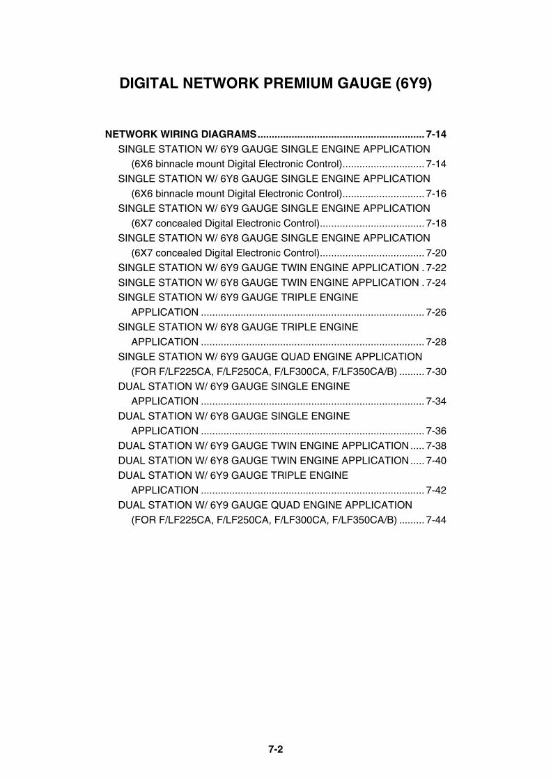
7-2
DIGITAL NETWORK PREMIUM GAUGE (6Y9)
NETWORK WIRING DIAGRAMS........................................................... 7-14SINGLE STATION W/ 6Y9 GAUGE SINGLE ENGINE APPLICATION
(6X6 binnacle mount Digital Electronic Control)............................. 7-14
SINGLE STATION W/ 6Y8 GAUGE SINGLE ENGINE APPLICATION
(6X6 binnacle mount Digital Electronic Control)............................. 7-16
SINGLE STATION W/ 6Y9 GAUGE SINGLE ENGINE APPLICATION
(6X7 concealed Digital Electronic Control)..................................... 7-18
SINGLE STATION W/ 6Y8 GAUGE SINGLE ENGINE APPLICATION
(6X7 concealed Digital Electronic Control)..................................... 7-20
SINGLE STATION W/ 6Y9 GAUGE TWIN ENGINE APPLICATION . 7-22
SINGLE STATION W/ 6Y8 GAUGE TWIN ENGINE APPLICATION . 7-24
SINGLE STATION W/ 6Y9 GAUGE TRIPLE ENGINE
APPLICATION ............................................................................... 7-26
SINGLE STATION W/ 6Y8 GAUGE TRIPLE ENGINE
APPLICATION ............................................................................... 7-28
SINGLE STATION W/ 6Y9 GAUGE QUAD ENGINE APPLICATION
(FOR F/LF225CA, F/LF250CA, F/LF300CA, F/LF350CA/B) ......... 7-30
DUAL STATION W/ 6Y9 GAUGE SINGLE ENGINE
APPLICATION ............................................................................... 7-34
DUAL STATION W/ 6Y8 GAUGE SINGLE ENGINE
APPLICATION ............................................................................... 7-36
DUAL STATION W/ 6Y9 GAUGE TWIN ENGINE APPLICATION..... 7-38
DUAL STATION W/ 6Y8 GAUGE TWIN ENGINE APPLICATION..... 7-40
DUAL STATION W/ 6Y9 GAUGE TRIPLE ENGINE
APPLICATION ............................................................................... 7-42
DUAL STATION W/ 6Y9 GAUGE QUAD ENGINE APPLICATION
(FOR F/LF225CA, F/LF250CA, F/LF300CA, F/LF350CA/B) ......... 7-44
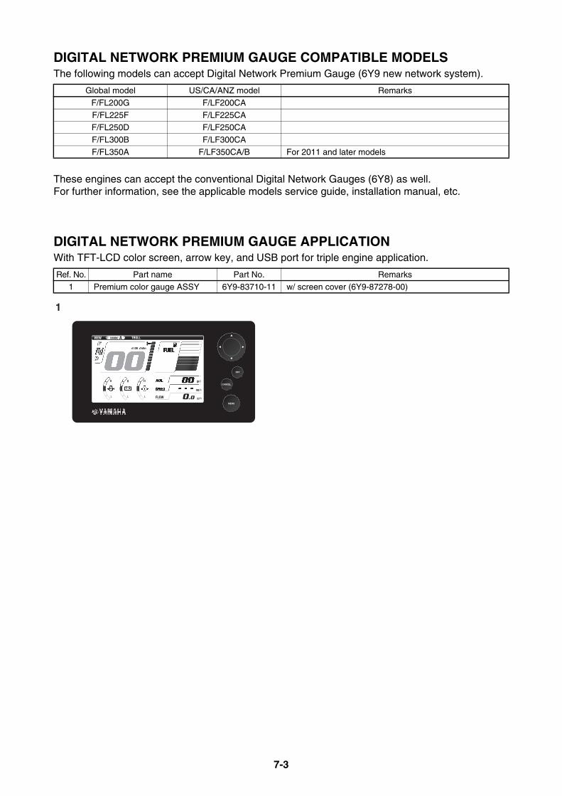
7-3
DIGITAL NETWORK PREMIUM GAUGE COMPATIBLE MODELSThe following models can accept Digital Network Premium Gauge (6Y9 new network system).
These engines can accept the conventional Digital Network Gauges (6Y8) as well.For further information, see the applicable models service guide, installation manual, etc.
DIGITAL NETWORK PREMIUM GAUGE APPLICATIONWith TFT-LCD color screen, arrow key, and USB port for triple engine application.
Global model US/CA/ANZ model Remarks
F/FL200G F/LF200CA
F/FL225F F/LF225CAF/FL250D F/LF250CA
F/FL300B F/LF300CA
F/FL350A F/LF350CA/B For 2011 and later models
Ref. No. Part name Part No. Remarks
1 Premium color gauge ASSY 6Y9-83710-11 w/ screen cover (6Y9-87278-00)
1
SET
MENU
CANCEL

7-4
DIGITAL NETWORK PREMIUM GAUGE DIMENSIONSPREMIUM COLOR GAUGE DIMENSIONS
98 (
3.86
)
Template
Reference: previous gauge
177.5 (6.99)
11.9 (0.47)
98 (3.86)
98 (
3.86
)
85.0
(3.
35)
45.0
(1.
77)
18.7
5 (0
.74)18.75
(0.74)127.0 (5.00)
164.5 (6.48)
38.0 (1.50)
4.2 (0.17)
mm (in.)
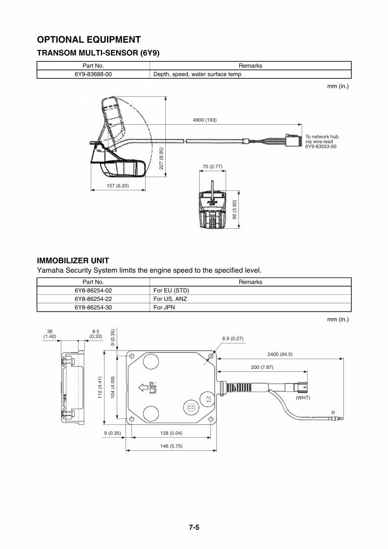
7-5
OPTIONAL EQUIPMENTTRANSOM MULTI-SENSOR (6Y9)
IMMOBILIZER UNITYamaha Security System limits the engine speed to the specified level.
Part No. Remarks6Y9-83688-00 Depth, speed, water surface temp
Part No. Remarks
6Y8-86254-02 For EU (STD)6Y8-86254-22 For US, ANZ
6Y8-86254-30 For JPN
157 (6.20)
4900 (193)
70 (2.77)
99 (
3.90
)
227
(8.9
5)
To network hubvia wire-lead6Y9-83553-60
mm (in.)
2400 (94.5)
200 (7.87)
(WHT)104
(4.0
9)9
(0.3
5)
112
(4.4
1)
128 (5.04)9 (0.35)
146 (5.75)
6.9 (0.27)
8.5(0.33)
36(1.42)
R
mm (in.)
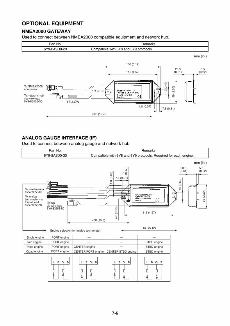
7-6
OPTIONAL EQUIPMENTNMEA2000 GATEWAYUsed to connect between NMEA2000 compatible equipment and network hub.
ANALOG GAUGE INTERFACE (IF)Used to connect between analog gauge and network hub.
Part No. Remarks
6Y9-8A2D0-20 Compatible with 6Y8 and 6Y9 protocols
Part No. Remarks6Y9-8A2D0-30 Compatible with 6Y8 and 6Y9 protocols, Required for each engine.
5.5(0.22)
20.5(0.81)116 (4.57)
130 (5.12)
To NMEA2000equipment
To network hubvia wire-lead6Y9-83553-50
12 (
0.47
)
1.8 (0.07)
4.8 (0.19)
56 (
2.20
)
7.8 (0.31)
500 (19.7)
20
YELLOW
mm (in.)
1.8
(0.0
7)
4.6
(0.1
8)
7.8 (0.31)
To wire-harness6Y5-83553-00
To analog tachometer via trim/oil lead6Y5-83653-*0
To hubvia wire-lead6Y9-83553-50
12 (0.4
7)
16 (
0.63
)
116 (4.57)
130 (5.12)
400 (15.8)
Engine selection for analog tachometer:
56 (
2.20
)
5.5 (0.22)
20.5(0.81)
BOrBLBOrBL BOrBLBOrBL
— —
— —
—CENTER engine
CENTER PORT engine CENTER STBD engine STBD enginePORT engine
PORT engine
PORT engine
PORT engine
Quad engine
Single engine
Twin engine
Triple engine
—
STBD engine
STBD engine
30
mm (in.)

7-7
OPTIONAL EQUIPMENTSPEED SENSOR KITUsed to pick up the pitot tube pressure for water speed.
COOLANT PRESSURE SENSOR KITUsed to pick up the coolant pressure of engine.
Kit Part No. Remarks
60V-8A4L1-13 Shared with 6Y8 network system
Kit Part No. Remarks
63P-8A4L0-01 Shared with 6Y8 network system
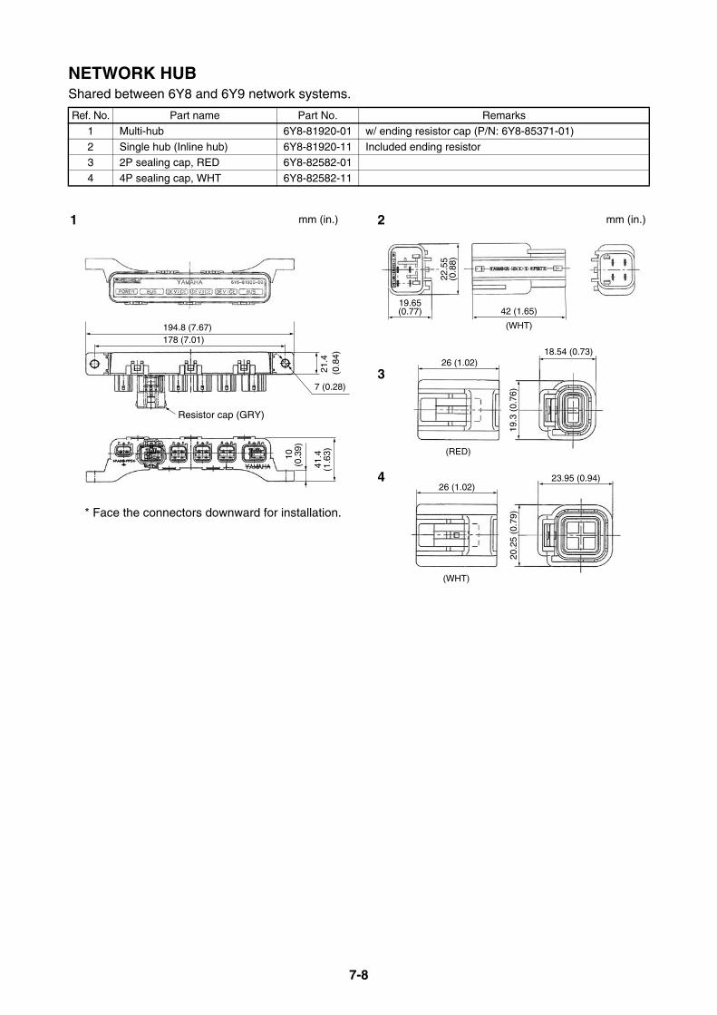
7-8
NETWORK HUBShared between 6Y8 and 6Y9 network systems.
Ref. No. Part name Part No. Remarks
1 Multi-hub 6Y8-81920-01 w/ ending resistor cap (P/N: 6Y8-85371-01)
2 Single hub (Inline hub) 6Y8-81920-11 Included ending resistor3 2P sealing cap, RED 6Y8-82582-01
4 4P sealing cap, WHT 6Y8-82582-11
178 (7.01)
Resistor cap (GRY)
194.8 (7.67)
7 (0.28)
41.4
(1.6
3)21
.4 (
0.84
)
10(0
.39)
22.5
5(0
.88)
19.65(0.77) 42 (1.65)
(WHT)
26 (1.02)18.54 (0.73)
19.3
(0.
76)
(RED)
23.95 (0.94)
20.2
5 (0
.79)
26 (1.02)
(WHT)
1 2
3
4
mm (in.)mm (in.)
* Face the connectors downward for installation.
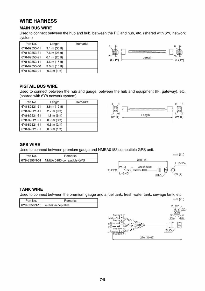
7-9
WIRE HARNESSMAIN BUS WIREUsed to connect between the hub and hub, between the RC and hub, etc. (shared with 6Y8 networksystem)
PIGTAIL BUS WIREUsed to connect between the hub and gauge, between the hub and equipment (IF, gateway), etc.(shared with 6Y8 network system)
GPS WIREUsed to connect between premium gauge and NMEA0183 compatible GPS unit.
TANK WIREUsed to connect between the premium gauge and a fuel tank, fresh water tank, sewage tank, etc.
Part No. Length Remarks
6Y8-82553-41 9.1 m (30 ft)6Y8-82553-31 7.6 m (25 ft)
6Y8-82553-21 6.1 m (20 ft)
6Y8-82553-11 4.6 m (15 ft)6Y8-82553-50 3.0 m (10 ft)
6Y8-82553-01 0.3 m (1 ft)
Part No. Length Remarks6Y8-82521-51 3.6 m (12 ft)
6Y8-82521-41 2.7 m (9 ft)
6Y8-82521-31 1.8 m (6 ft)6Y8-82521-21 0.9 m (3 ft)
6Y8-82521-11 0.6 m (2 ft)
6Y8-82521-01 0.3 m (1 ft)
Part No. Remarks
6Y9-8356N-01 NMEA 0183 compatible GPS
Part No. Remarks6Y9-8356N-10 4-tank acceptable
Length(GRY) (GRY)
R B
W
R B
W LL
Length
B R
WL
B R
WL
(WHT) (WHT)
To GPS
350 (14)
(BLK)
L (GND)W (+)
L (GND) W (+)
Green tube
mm (in.)
270 (10.63)
(BLK)
B/G
GB/PP
Or
B/OrPB/P
GB/G
BrB/Br
OrB/Or
Br
B/Br
Fuel tank #1
Fuel tank #2
Fuel tank #3
Fuel tank #4
mm (in.)
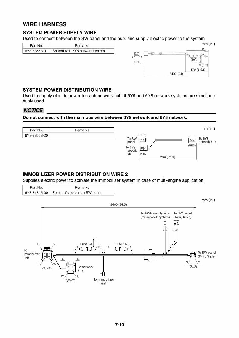
7-10
WIRE HARNESSSYSTEM POWER SUPPLY WIREUsed to connect between the SW panel and the hub, and supply electric power to the system.
SYSTEM POWER DISTRIBUTION WIREUsed to supply electric power to each network hub, if 6Y9 and 6Y8 network systems are simultane-ously used.
NOTICEDo not connect with the main bus wire between 6Y9 network and 6Y8 network.
IMMOBILIZER POWER DISTRIBUTION WIRE 2Supplies electric power to activate the immobilizer system in case of multi-engine application.
Part No. Remarks
6Y8-83553-01 Shared with 6Y8 network system
Part No. Remarks6Y9-83553-20
Part No. Remarks6Y8-81315-00 For start/stop button SW panel
2400 (94)
70 (2.75)
170 (6.63)
(10A)B
(RED)
Y
B
YY
mm (in.)
(RED)
(RED)
Y B
B Y
B Y
(RED)
600 (23.6)
To SW panel
To 6Y9 networkhub
To 6Y8 network hub
mm (in.)
2400 (94.5)
To SW panel(Twin, Triple)
To PWR supply wire(for network system)
Fuse 5AFuse 5A
To immobilizerunit
To network hub
To immobilizer unit
To SW panel(Twin, Triple)
(WHT)
(WHT)
(BLU)W
R R
R
Y Y
Y Y Y R
L
YB
LW
BXR Y
mm (in.)
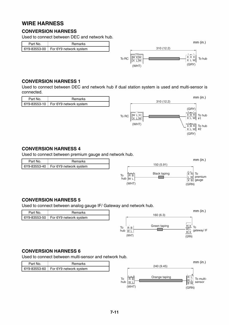
7-11
WIRE HARNESSCONVERSION HARNESSUsed to connect between DEC and network hub.
CONVERSION HARNESS 1Used to connect between DEC and network hub if dual station system is used and multi-sensor isconnected.
CONVERSION HARNESS 4Used to connect between premium gauge and network hub.
CONVERSION HARNESS 5Used to connect between analog gauge IF/ Gateway and network hub.
CONVERSION HARNESS 6Used to connect between multi-sensor and network hub.
Part No. Remarks
6Y9-83553-00 For 6Y9 network system
Part No. Remarks6Y9-83553-10 For 6Y9 network system
Part No. Remarks
6Y9-83553-40 For 6Y9 network system
Part No. Remarks6Y9-83553-50 For 6Y9 network system
Part No. Remarks
6Y9-83553-60 For 6Y9 network system
310 (12.2)
(WHT)
WX
XL
WW
XX
XL
XW
(GRY)
To RC To hub
mm (in.)
310 (12.2)
(WHT)
WX
LL
XW
XX
BL
RW
XX
BL
RW
(GRY)
(GRY)
To RC To hub#1
To hub#2
mm (in.)
150 (5.91)
(WHT)
RW
BL
XL
RW
X B
(GRN)
Black tapingTo hub
To premium gauge
mm (in.)
160 (6.3)
(WHT)
RW
BL
RW
XL
B X
(GRN)
Green tapingTohub
Togateway/ IF
mm (in.)
240 (9.45)
(WHT)
RW
BL
RW
LL
B W
(GRN)
Orange tapingTo hub
To multi-sensor
mm (in.)
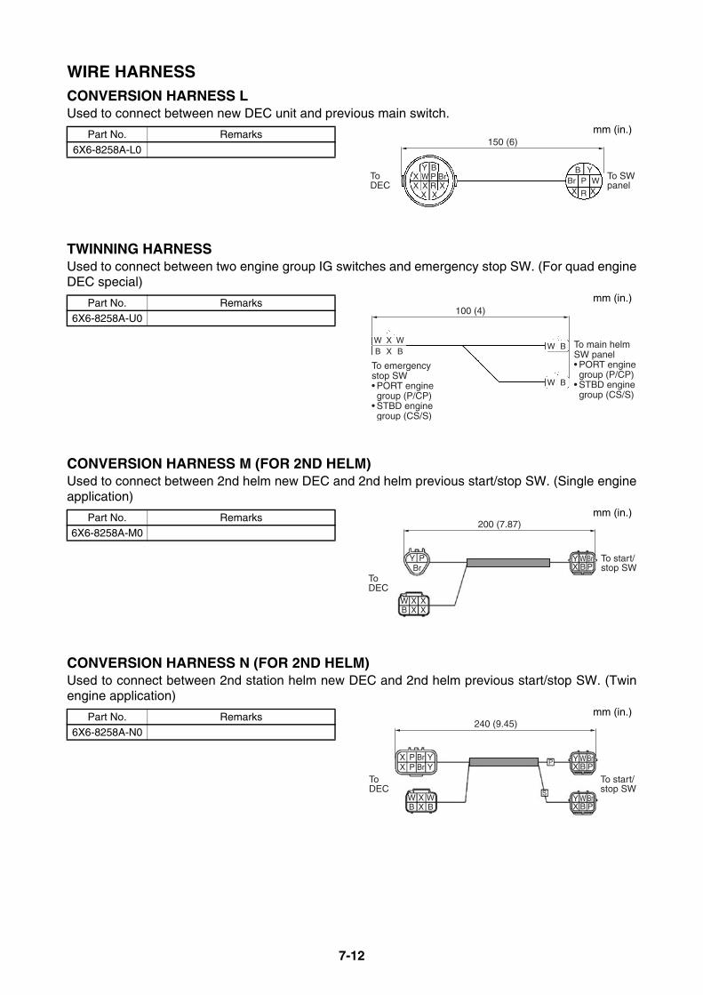
7-12
WIRE HARNESSCONVERSION HARNESS LUsed to connect between new DEC unit and previous main switch.
TWINNING HARNESS Used to connect between two engine group IG switches and emergency stop SW. (For quad engineDEC special)
CONVERSION HARNESS M (FOR 2ND HELM)Used to connect between 2nd helm new DEC and 2nd helm previous start/stop SW. (Single engineapplication)
CONVERSION HARNESS N (FOR 2ND HELM)Used to connect between 2nd station helm new DEC and 2nd helm previous start/stop SW. (Twinengine application)
Part No. Remarks
6X6-8258A-L0
Part No. Remarks6X6-8258A-U0
Part No. Remarks6X6-8258A-M0
Part No. Remarks
6X6-8258A-N0
150 (6)
Y B
X X
WX P BrXX R X
B YBr P WX R X
ToDEC
To SWpanel
mm (in.)
100 (4)
W X WB X B
W B
W B
To emergency stop SW• PORT engine group (P/CP)• STBD engine group (CS/S)
To main helmSW panel• PORT engine group (P/CP)• STBD engine group (CS/S)
mm (in.)
200 (7.87)
Y PBr
WB
XX
XX
YX
WB
BrP
To DEC
To start/stop SW
mm (in.)
240 (9.45)
XX
PP
BrBr
WB
XX
WB
YX
S
P WB
BrP
YX
WB
BrP
YY
To DEC
To start/stop SW
mm (in.)

7-13
WIRE HARNESSCONVERSION HARNESS P (FOR 2ND HELM)Used to connect between 2nd helm new DEC and 2nd helm previous start/stop SW. (Triple engineapplication)
CONVERSION HARNESS K (FOR DUAL STATION)Used to connect between main helm new DEC and 2nd helm previous DEC.
Part No. Remarks
6X6-8258A-P0
Part No. Remarks
6X6-8258A-K0
240 (9.45)
XX
PP
BrBr
WB
WB
WB
YX
S
C
P WB
BrP
YX
WB
BrP
YX
WB
BrP
YY
X P Br Y
To DEC
To start/stop SW
mm (in.)
230 (9.06)
Br Br
BrX
Y Br BrXYBr
To previousDEC
TonewDEC
mm (in.)
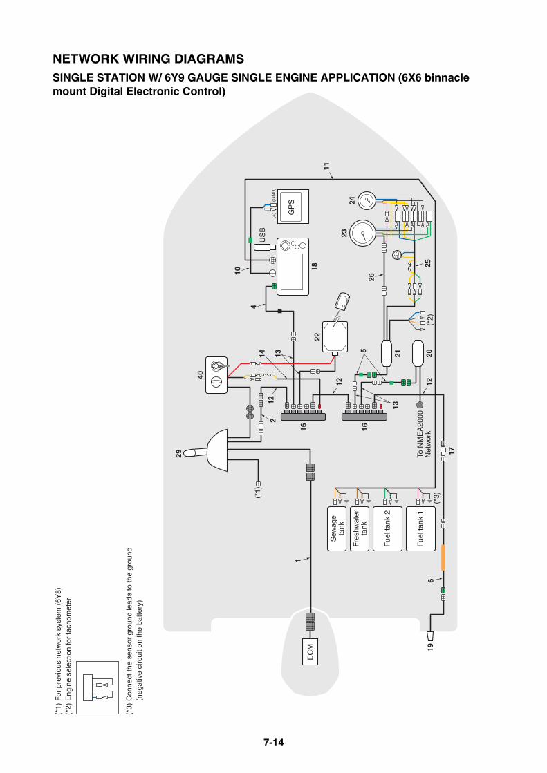
7-14
(*3)
18
US
B
29
GP
S
40
22E
CM
(*1)
(*2)
17
Fue
l tan
k 2
Fue
l tan
k 1
Fres
hwat
erta
nk
Sew
age
tank
To N
ME
A20
00N
etw
ork
(*1)
For
pre
viou
s ne
twor
k sy
stem
(6Y
8)(*
2) E
ngin
e se
lect
ion
for
tach
omet
er
(*3)
Con
nect
the
sens
or g
roun
d le
ads
to th
e gr
ound
(neg
ativ
e ci
rcui
t on
the
batte
ry)
6
16 1626
2324
2520
4
2
1
11
131412
5
21
12
13
1219
10
(+
)(G
ND
)
NETWORK WIRING DIAGRAMSSINGLE STATION W/ 6Y9 GAUGE SINGLE ENGINE APPLICATION (6X6 binnacle mount Digital Electronic Control)
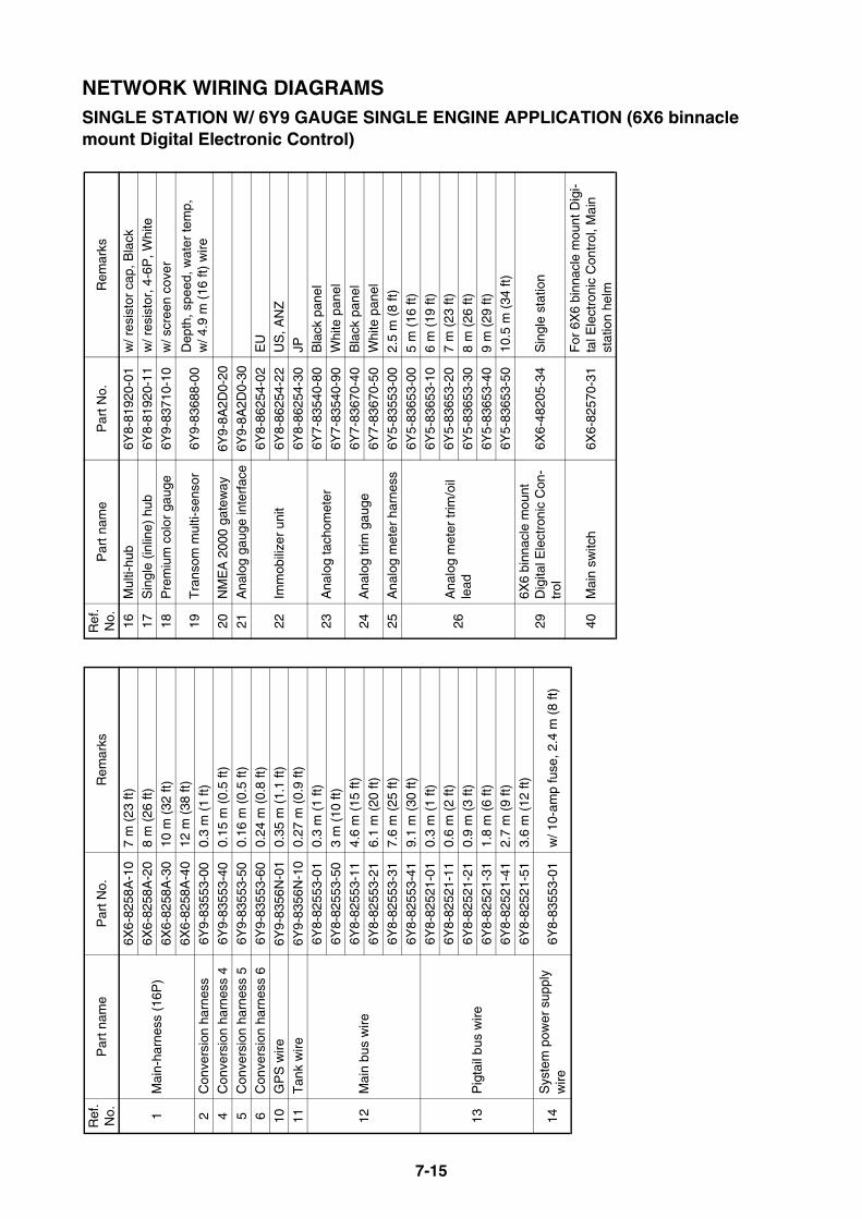
7-15
NETWORK WIRING DIAGRAMSSINGLE STATION W/ 6Y9 GAUGE SINGLE ENGINE APPLICATION (6X6 binnacle mount Digital Electronic Control)
Ref
. N
o.P
art n
ame
Par
t No.
Rem
arks
1M
ain-
harn
ess
(16P
)
6X6-
8258
A-1
07
m (
23 ft
)6X
6-82
58A
-20
8 m
(26
ft)
6X6-
8258
A-3
010
m (
32 ft
)
6X6-
8258
A-4
012
m (
38 ft
)2
Con
vers
ion
harn
ess
6Y9-
8355
3-00
0.3
m (
1 ft)
4C
onve
rsio
n ha
rnes
s 4
6Y9-
8355
3-40
0.15
m (
0.5
ft)
5C
onve
rsio
n ha
rnes
s 5
6Y9-
8355
3-50
0.16
m (
0.5
ft)6
Con
vers
ion
harn
ess
66Y
9-83
553-
600.
24 m
(0.
8 ft)
10G
PS
wire
6Y9-
8356
N-0
10.
35 m
(1.
1 ft)
11T
ank
wire
6Y9-
8356
N-1
00.
27 m
(0.
9 ft)
12M
ain
bus
wire
6Y8-
8255
3-01
0.3
m (
1 ft)
6Y8-
8255
3-50
3 m
(10
ft)
6Y8-
8255
3-11
4.6
m (
15 ft
)
6Y8-
8255
3-21
6.1
m (
20 ft
)6Y
8-82
553-
317.
6 m
(25
ft)
6Y8-
8255
3-41
9.1
m (
30 ft
)
13P
igta
il bu
s w
ire
6Y8-
8252
1-01
0.3
m (
1 ft)
6Y8-
8252
1-11
0.6
m (
2 ft)
6Y8-
8252
1-21
0.9
m (
3 ft)
6Y8-
8252
1-31
1.8
m (
6 ft)
6Y8-
8252
1-41
2.7
m (
9 ft)
6Y8-
8252
1-51
3.6
m (
12 ft
)
14S
yste
m p
ower
sup
ply
wire
6Y8-
8355
3-01
w/ 1
0-am
p fu
se, 2
.4 m
(8
ft)
16M
ulti-
hub
6Y8-
8192
0-01
w/ r
esis
tor
cap,
Bla
ck17
Sin
gle
(inlin
e) h
ub6Y
8-81
920-
11w
/ res
isto
r, 4
-6P
, Whi
te
18P
rem
ium
col
or g
auge
6Y9-
8371
0-10
w/ s
cree
n co
ver
19T
rans
om m
ulti-
sens
or6Y
9-83
688-
00D
epth
, spe
ed, w
ater
tem
p,
w/ 4
.9 m
(16
ft)
wire
20N
ME
A 2
000
gate
way
6Y9-
8A2D
0-20
21A
nalo
g ga
uge
inte
rfac
e6Y
9-8A
2D0-
30
22Im
mob
ilize
r un
it
6Y8-
8625
4-02
EU
6Y8-
8625
4-22
US
, AN
Z
6Y8-
8625
4-30
JP
23A
nalo
g ta
chom
eter
6Y7-
8354
0-80
Bla
ck p
anel
6Y7-
8354
0-90
Whi
te p
anel
24A
nalo
g tr
im g
auge
6Y7-
8367
0-40
Bla
ck p
anel
6Y7-
8367
0-50
Whi
te p
anel
25A
nalo
g m
eter
har
ness
6Y5-
8355
3-00
2.5
m (
8 ft)
26A
nalo
g m
eter
trim
/oil
lead
6Y5-
8365
3-00
5 m
(16
ft)
6Y5-
8365
3-10
6 m
(19
ft)
6Y5-
8365
3-20
7 m
(23
ft)
6Y5-
8365
3-30
8 m
(26
ft)
6Y5-
8365
3-40
9 m
(29
ft)
6Y5-
8365
3-50
10.5
m (
34 ft
)
296X
6 bi
nnac
le m
ount
D
igita
l Ele
ctro
nic
Con
-tr
ol6X
6-48
205-
34S
ingl
e st
atio
n
40M
ain
switc
h6X
6-82
570-
31F
or 6
X6
binn
acle
mou
nt D
igi-
tal E
lect
roni
c C
ontr
ol, M
ain
stat
ion
helm
Ref
. N
o.P
art n
ame
Par
t No.
Rem
arks

7-16
29
EC
M
(*1)
17
(*1)
For
6Y
9 ne
twor
k sy
stem
161
SP
EE
D/F
UE
LTA
CH
Fue
l tan
k 1
GP
S
13
40
14
1313
9
16
22
12
12
(GN
D)
(+)
Not
use
d
19
NETWORK WIRING DIAGRAMSSINGLE STATION W/ 6Y8 GAUGE SINGLE ENGINE APPLICATION (6X6 binnacle mount Digital Electronic Control)

7-17
NETWORK WIRING DIAGRAMSSINGLE STATION W/ 6Y8 GAUGE SINGLE ENGINE APPLICATION (6X6 binnacle mount Digital Electronic Control)
Ref
. N
o.P
art n
ame
Par
t No.
Rem
arks
1M
ain-
harn
ess
(16P
)
6X6-
8258
A-1
07
m (
23 ft
)6X
6-82
58A
-20
8 m
(26
ft)
6X6-
8258
A-3
010
m (
32 ft
)
6X6-
8258
A-4
012
m (
38 ft
)9
Fue
l tan
k/ G
PS
wire
6Y8-
8356
N-0
10.
3 m
(1
ft)
12M
ain
bus
wire
6Y8-
8255
3-01
0.3
m (
1 ft)
6Y8-
8255
3-50
3 m
(10
ft)
6Y8-
8255
3-11
4.5
m (
15 ft
)
6Y8-
8255
3-21
6.1
m (
20 ft
)
6Y8-
8255
3-31
7.6
m (
25 ft
)6Y
8-82
553-
419.
1 m
(30
ft)
13P
igta
il bu
s w
ire
6Y8-
8252
1-01
0.3
m (
1 ft)
6Y8-
8252
1-11
0.6
m (
2 ft)
6Y8-
8252
1-21
0.9
m (
3 ft)
6Y8-
8252
1-31
1.8
m (
6 ft)
6Y8-
8252
1-41
2.7
m (
9 ft)
6Y8-
8252
1-51
3.6
m (
12 ft
)
14S
yste
m p
ower
sup
ply
wire
6Y8-
8355
3-01
w/ 1
0-am
p fu
se, 2
.4 m
, 8 ft
16M
ulti-
hub
6Y8-
8192
0-01
w/ r
esis
tor
cap,
Bla
ck
17S
ingl
e (in
line)
hub
6Y8-
8192
0-11
w/ r
esis
tor,
4-6
P, W
hite
19T
rans
om m
ulti-
sens
or6Y
8-83
688-
01D
epth
, spe
ed, w
ater
tem
p,
w/ 4
.9 m
(15
ft)
wire
22Im
mob
ilize
r un
it6Y
8-86
254-
02E
U6Y
8-86
254-
22U
S, A
NZ
6Y8-
8625
4-30
JP
296X
6 bi
nnac
le m
ount
D
igita
l Ele
ctro
nic
Con
-tr
ol6X
6-48
205-
34S
ingl
e st
atio
n
40M
ain
switc
h6X
6-82
570-
31F
or 6
X6
binn
acle
mou
nt D
igi-
tal E
lect
roni
c C
ontr
ol, M
ain
stat
ion
helm
Ref
. N
o.P
art n
ame
Par
t No.
Rem
arks
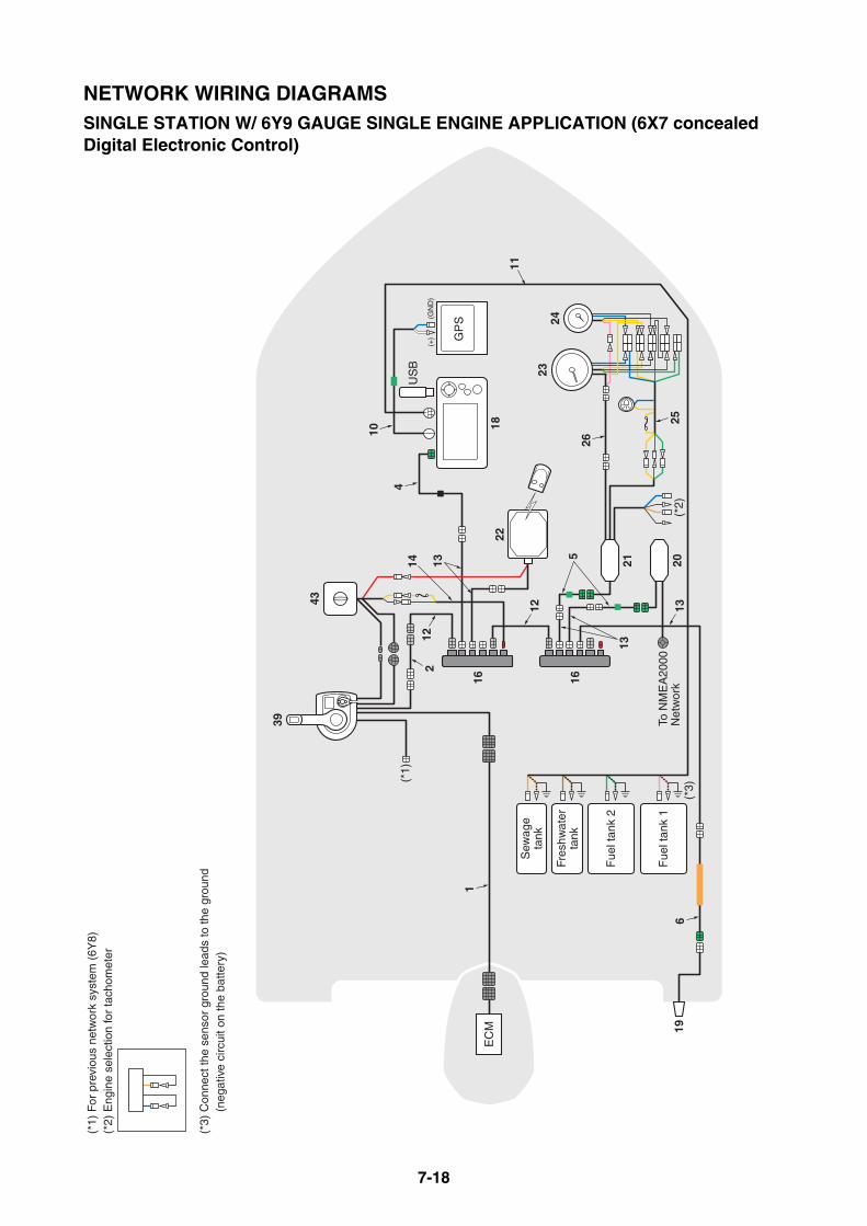
7-18
(*3)
18
US
B
21 20
16 16
GP
S
22E
CM
(*2)
2324
1
Fue
l tan
k 2
Fue
l tan
k 1
Fres
hwat
erta
nk
Sew
age
tank
39
(*1)
To N
ME
A20
00N
etw
ork
25
43
(*1)
For
pre
viou
s ne
twor
k sy
stem
(6Y
8)(*
2) E
ngin
e se
lect
ion
for
tach
omet
er
(*3)
Con
nect
the
sens
or g
roun
d le
ads
to th
e gr
ound
(neg
ativ
e ci
rcui
t on
the
batte
ry)
2
4
6
26
19
11
121314
5
12
13
13
10
(+
) (
GN
D)
NETWORK WIRING DIAGRAMSSINGLE STATION W/ 6Y9 GAUGE SINGLE ENGINE APPLICATION (6X7 concealed Digital Electronic Control)
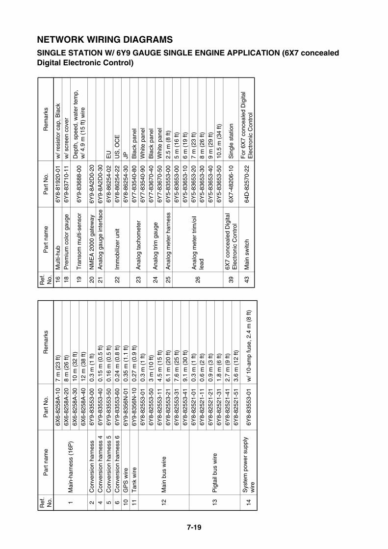
7-19
NETWORK WIRING DIAGRAMSSINGLE STATION W/ 6Y9 GAUGE SINGLE ENGINE APPLICATION (6X7 concealed Digital Electronic Control)
Ref
. N
o.P
art n
ame
Par
t No.
Rem
arks
1M
ain-
harn
ess
(16P
)
6X6-
8258
A-1
07
m (
23 ft
)6X
6-82
58A
-20
8 m
(26
ft)
6X6-
8258
A-3
010
m (
32 ft
)
6X6-
8258
A-4
012
m (
38 ft
)2
Con
vers
ion
harn
ess
6Y9-
8355
3-00
0.3
m (
1 ft)
4C
onve
rsio
n ha
rnes
s 4
6Y9-
8355
3-40
0.15
m (
0.5
ft)
5C
onve
rsio
n ha
rnes
s 5
6Y9-
8355
3-50
0.16
m (
0.5
ft)6
Con
vers
ion
harn
ess
66Y
9-83
553-
600.
24 m
(0.
8 ft)
10G
PS
wire
6Y9-
8356
N-0
10.
35 m
(1.
1 ft)
11T
ank
wire
6Y9-
8356
N-1
00.
27 m
(0.
9 ft)
12M
ain
bus
wire
6Y8-
8255
3-01
0.3
m (
1 ft)
6Y8-
8255
3-50
3 m
(10
ft)
6Y8-
8255
3-11
4.5
m (
15 ft
)
6Y8-
8255
3-21
6.1
m (
20 ft
)6Y
8-82
553-
317.
6 m
(25
ft)
6Y8-
8255
3-41
9.1
m (
30 ft
)
13P
igta
il bu
s w
ire
6Y8-
8252
1-01
0.3
m (
1 ft)
6Y8-
8252
1-11
0.6
m (
2 ft)
6Y8-
8252
1-21
0.9
m (
3 ft)
6Y8-
8252
1-31
1.8
m (
6 ft)
6Y8-
8252
1-41
2.7
m (
9 ft)
6Y8-
8252
1-51
3.6
m (
12 ft
)
14S
yste
m p
ower
sup
ply
wire
6Y8-
8355
3-01
w/ 1
0-am
p fu
se, 2
.4 m
(8
ft)
16M
ulti-
hub
6Y8-
8192
0-01
w/ r
esis
tor
cap,
Bla
ck18
Pre
miu
m c
olor
gau
ge6Y
9-83
710-
11w
/ scr
een
cove
r
19T
rans
om m
ulti-
sens
or6Y
9-83
688-
00D
epth
, spe
ed, w
ater
tem
p,
w/ 4
.9 m
(15
ft)
wire
20N
ME
A 2
000
gate
way
6Y9-
8A2D
0-20
21A
nalo
g ga
uge
inte
rfac
e6Y
9-8A
2D0-
30
22Im
mob
ilize
r un
it6Y
8-86
254-
02E
U6Y
8-86
254-
22U
S, O
CE
6Y8-
8625
4-30
JP
23A
nalo
g ta
chom
eter
6Y7-
8354
0-80
Bla
ck p
anel
6Y7-
8354
0-90
Whi
te p
anel
24A
nalo
g tr
im g
auge
6Y7-
8367
0-40
Bla
ck p
anel
6Y7-
8367
0-50
Whi
te p
anel
25A
nalo
g m
eter
har
ness
6Y5-
8355
3-00
2.5
m (
8 ft)
26A
nalo
g m
eter
trim
/oil
lead
6Y5-
8365
3-00
5 m
(16
ft)
6Y5-
8365
3-10
6 m
(19
ft)
6Y5-
8365
3-20
7 m
(23
ft)
6Y5-
8365
3-30
8 m
(26
ft)
6Y5-
8365
3-40
9 m
(29
ft)
6Y5-
8365
3-50
10.5
m (
34 ft
)
396X
7 co
ncea
led
Dig
ital
Ele
ctro
nic
Con
trol
6X7-
4820
6-10
Sin
gle
stat
ion
43M
ain
switc
h64
D-8
2570
-22
For
6X
7 co
ncea
led
Dig
ital
Ele
ctro
nic
Con
trol
Ref
. N
o.P
art n
ame
Par
t No.
Rem
arks
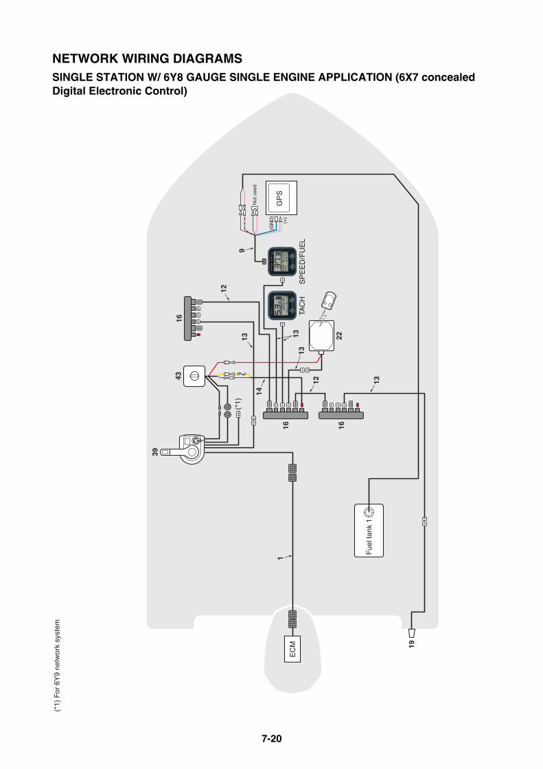
7-20
16 16
EC
M
1
39
43
(*1)
For
6Y
9 ne
twor
k sy
stem
19
SP
EE
D/F
UE
LTA
CH
GP
S
Fue
l tan
k 1
(*1)
13
14
12
16
22
12
9
1313
13
(GN
D)
(+)
Not
use
d
NETWORK WIRING DIAGRAMSSINGLE STATION W/ 6Y8 GAUGE SINGLE ENGINE APPLICATION (6X7 concealed Digital Electronic Control)
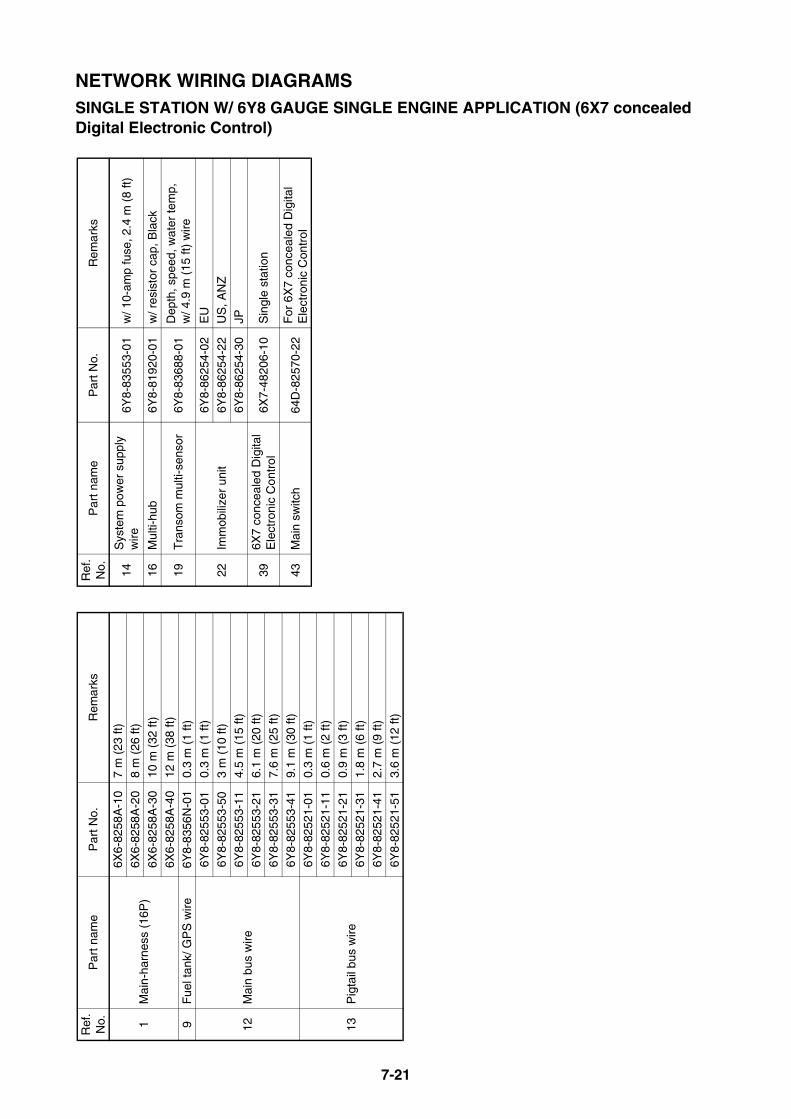
7-21
NETWORK WIRING DIAGRAMSSINGLE STATION W/ 6Y8 GAUGE SINGLE ENGINE APPLICATION (6X7 concealed Digital Electronic Control)
Ref
. N
o.P
art n
ame
Par
t No.
Rem
arks
1M
ain-
harn
ess
(16P
)
6X6-
8258
A-1
07
m (
23 ft
)6X
6-82
58A
-20
8 m
(26
ft)
6X6-
8258
A-3
010
m (
32 ft
)
6X6-
8258
A-4
012
m (
38 ft
)9
Fue
l tan
k/ G
PS
wire
6Y8-
8356
N-0
10.
3 m
(1
ft)
12M
ain
bus
wire
6Y8-
8255
3-01
0.3
m (
1 ft)
6Y8-
8255
3-50
3 m
(10
ft)
6Y8-
8255
3-11
4.5
m (
15 ft
)
6Y8-
8255
3-21
6.1
m (
20 ft
)
6Y8-
8255
3-31
7.6
m (
25 ft
)6Y
8-82
553-
419.
1 m
(30
ft)
13P
igta
il bu
s w
ire
6Y8-
8252
1-01
0.3
m (
1 ft)
6Y8-
8252
1-11
0.6
m (
2 ft)
6Y8-
8252
1-21
0.9
m (
3 ft)
6Y8-
8252
1-31
1.8
m (
6 ft)
6Y8-
8252
1-41
2.7
m (
9 ft)
6Y8-
8252
1-51
3.6
m (
12 ft
)
14S
yste
m p
ower
sup
ply
wire
6Y8-
8355
3-01
w/ 1
0-am
p fu
se, 2
.4 m
(8
ft)
16M
ulti-
hub
6Y8-
8192
0-01
w/ r
esis
tor
cap,
Bla
ck
19T
rans
om m
ulti-
sens
or6Y
8-83
688-
01D
epth
, spe
ed, w
ater
tem
p,
w/ 4
.9 m
(15
ft)
wire
22Im
mob
ilize
r un
it
6Y8-
8625
4-02
EU
6Y8-
8625
4-22
US
, AN
Z6Y
8-86
254-
30JP
396X
7 co
ncea
led
Dig
ital
Ele
ctro
nic
Con
trol
6X7-
4820
6-10
Sin
gle
stat
ion
43M
ain
switc
h64
D-8
2570
-22
For
6X
7 co
ncea
led
Dig
ital
Ele
ctro
nic
Con
trol
Ref
. N
o.P
art n
ame
Par
t No.
Rem
arks
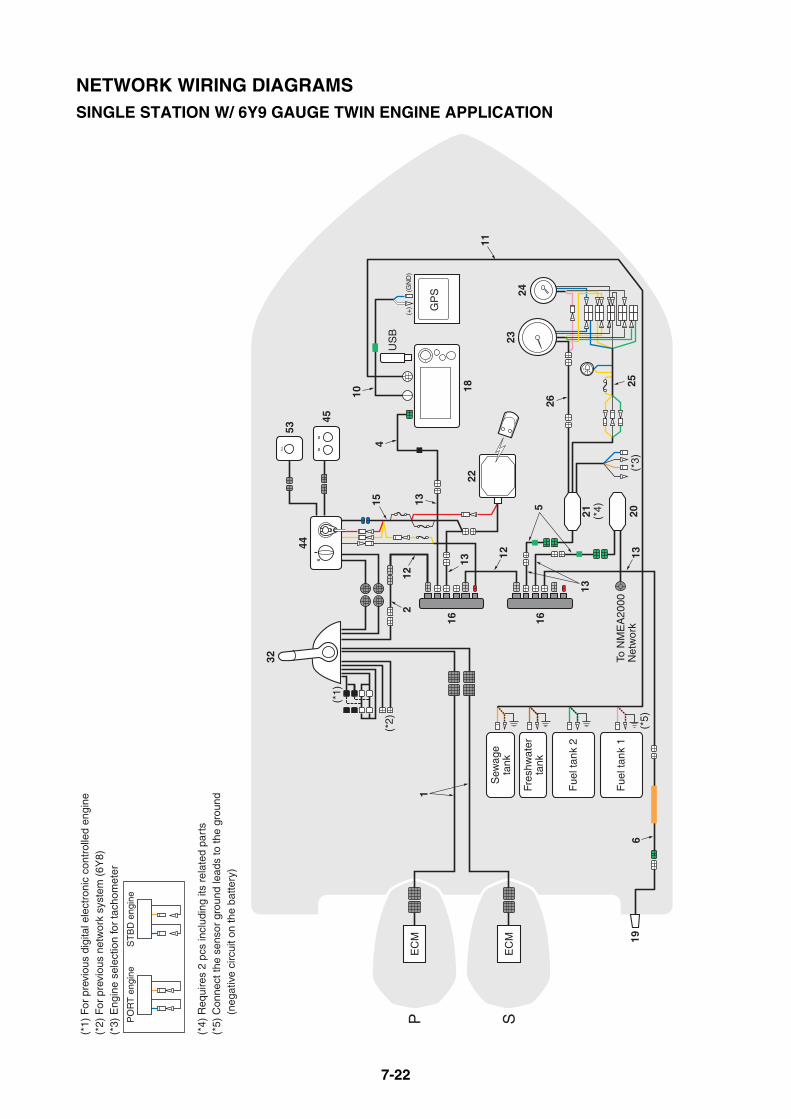
7-22
(*5)
32
EC
M
EC
MP S
(*1)
53
45
44
18
Fue
l tan
k 2
Fue
l tan
k 1
US
B
21 (*4) 20
GP
S
(*3)
Fres
hwat
erta
nk
Sew
age
tank
22
(*2)
To N
ME
A20
00N
etw
ork
(*1)
For
pre
viou
s di
gita
l ele
ctro
nic
cont
rolle
d en
gine
(*2)
For
pre
viou
s ne
twor
k sy
stem
(6Y
8)(*
3) E
ngin
e se
lect
ion
for
tach
omet
er
(*4)
Req
uire
s 2
pcs
incl
udin
g its
rel
ated
par
ts(*
5) C
onne
ct th
e se
nsor
gro
und
lead
s to
the
grou
nd
(n
egat
ive
circ
uit o
n th
e ba
ttery
)
PO
RT
eng
ine
ST
BD
eng
ine
16 16
15
2324
26
256
19
113
13
4
11
12
5
12
13
13
10
2 (
+)
(G
ND
)
NETWORK WIRING DIAGRAMSSINGLE STATION W/ 6Y9 GAUGE TWIN ENGINE APPLICATION
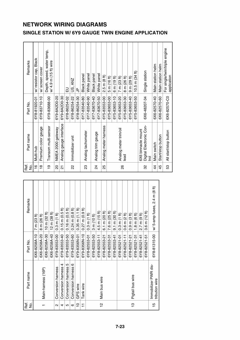
7-23
NETWORK WIRING DIAGRAMSSINGLE STATION W/ 6Y9 GAUGE TWIN ENGINE APPLICATION
Ref
. N
o.P
art n
ame
Par
t No.
Rem
arks
1M
ain-
harn
ess
(16P
)
6X6-
8258
A-1
07
m (
23 ft
)6X
6-82
58A
-20
8 m
(26
ft)
6X6-
8258
A-3
010
m (
32 ft
)
6X6-
8258
A-4
012
m (
38 ft
)2
Con
vers
ion
harn
ess
6Y9-
8355
3-00
0.3
m (
1 ft)
4C
onve
rsio
n ha
rnes
s 4
6Y9-
8355
3-40
0.15
m (
0.5
ft)
5C
onve
rsio
n ha
rnes
s 5
6Y9-
8355
3-50
0.16
m (
0.5
ft)6
Con
vers
ion
harn
ess
66Y
9-83
553-
600.
24 m
(0.
8 ft)
10G
PS
wire
6Y9-
8356
N-0
10.
35 m
(1.
1 ft)
11T
ank
wire
6Y9-
8356
N-1
00.
27 m
(0.
9 ft)
12M
ain
bus
wire
6Y8-
8255
3-01
0.3
m (
1 ft)
6Y8-
8255
3-50
3 m
(10
ft)
6Y8-
8255
3-11
4.5
m (
15 ft
)
6Y8-
8255
3-21
6.1
m (
20 ft
)6Y
8-82
553-
317.
6 m
(25
ft)
6Y8-
8255
3-41
9.1
m (
30 ft
)
13P
igta
il bu
s w
ire
6Y8-
8252
1-01
0.3
m (
1 ft)
6Y8-
8252
1-11
0.6
m (
2 ft)
6Y8-
8252
1-21
0.9
m (
3 ft)
6Y8-
8252
1-31
1.8
m (
6 ft)
6Y8-
8252
1-41
2.7
m (
9 ft)
6Y8-
8252
1-51
3.6
m (
12 ft
)
15Im
mob
ilize
r P
WR
dis
-tr
ibut
ion
wire
6Y8-
8131
5-00
w/ 5
-am
p fu
ses,
2.4
m (
8 ft)
16M
ulti-
hub
6Y8-
8192
0-01
w/ r
esis
tor
cap,
Bla
ck18
Pre
miu
m c
olor
gau
ge6Y
9-83
710-
10w
/ scr
een
cove
r
19T
rans
om m
ulti-
sens
or6Y
9-83
688-
00D
epth
, spe
ed, w
ater
tem
p,
w/ 4
.9 m
(15
ft)
wire
20N
ME
A 2
000
gate
way
6Y9-
8A2D
0-20
21A
nalo
g ga
uge
inte
rfac
e6Y
9-8A
2D0-
30
22Im
mob
ilize
r un
it6Y
8-86
254-
02E
U6Y
8-86
254-
22U
S, A
NZ
6Y8-
8625
4-30
JP
23A
nalo
g ta
chom
eter
6Y7-
8354
0-80
Bla
ck p
anel
6Y7-
8354
0-90
Whi
te p
anel
24A
nalo
g tr
im g
auge
6Y7-
8367
0-40
Bla
ck p
anel
6Y7-
8367
0-50
Whi
te p
anel
25A
nalo
g m
eter
har
ness
6Y5-
8355
3-00
2.5
m (
8 ft)
26A
nalo
g m
eter
trim
/oil
lead
6Y5-
8365
3-00
5 m
(16
ft)
6Y5-
8365
3-10
6 m
(19
ft)
6Y5-
8365
3-20
7 m
(23
ft)
6Y5-
8365
3-30
8 m
(26
ft)
6Y5-
8365
3-40
9 m
(29
ft)
6Y5-
8365
3-50
10.5
m (
34 ft
)
326X
6 bi
nnac
le m
ount
D
igita
l Ele
ctro
nic
Con
-tr
ol6X
6-48
207-
34S
ingl
e st
atio
n
44M
ain
switc
h6X
6-82
570-
40M
ain
stat
ion
helm
45S
tart
/sto
p bu
tton
6X6-
8257
0-60
Mai
n st
atio
n he
lm
53A
ll st
art/s
top
butto
n6X
6-82
570-
C0
For
sin
gle/
twin
/trip
le e
ngin
e ap
plic
atio
n
Ref
. N
o.P
art n
ame
Par
t No.
Rem
arks
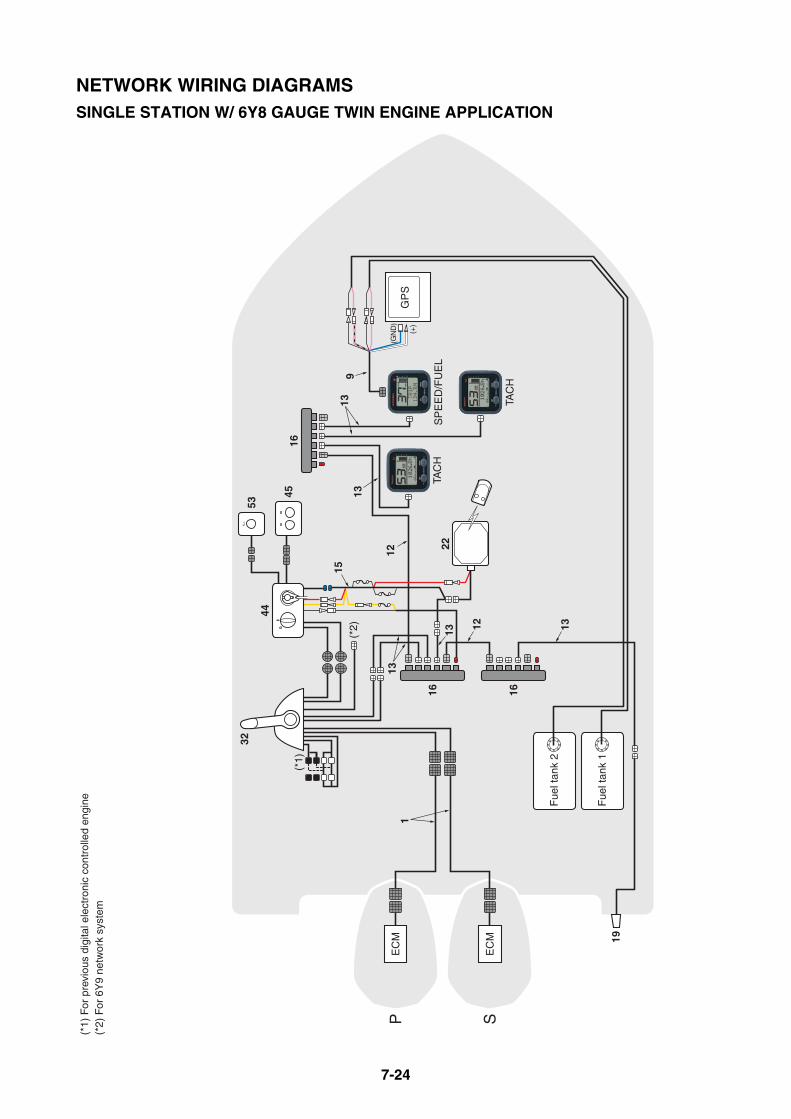
7-24
EC
M
EC
MP S
(*1)
For
pre
viou
s di
gita
l ele
ctro
nic
cont
rolle
d en
gine
(*2)
For
6Y
9 ne
twor
k sy
stem
16 16
16
19
SP
EE
D/F
UE
LTA
CH
TAC
H
GP
S
Fue
l tan
k 2
(*2)
Fue
l tan
k 1
13
1
32
(*1)
12
53
45
44
12
139
22
15
13
13
13
(GN
D)
(+)
NETWORK WIRING DIAGRAMSSINGLE STATION W/ 6Y8 GAUGE TWIN ENGINE APPLICATION
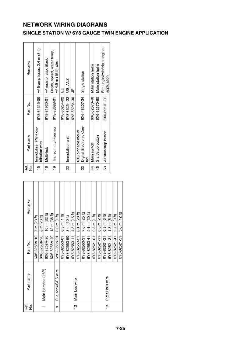
7-25
NETWORK WIRING DIAGRAMSSINGLE STATION W/ 6Y8 GAUGE TWIN ENGINE APPLICATION
Ref
. N
o.P
art n
ame
Par
t No.
Rem
arks
1M
ain-
harn
ess
(16P
)
6X6-
8258
A-1
07
m (
23 ft
)6X
6-82
58A
-20
8 m
(26
ft)
6X6-
8258
A-3
010
m (
32 ft
)
6X6-
8258
A-4
012
m (
38 ft
)9
Fue
l tan
k/G
PS
wire
6Y8-
8356
N-0
10.
3 m
(1
ft)
12M
ain
bus
wire
6Y8-
8255
3-01
0.3
m (
1 ft)
6Y8-
8255
3-50
3 m
(10
ft)
6Y8-
8255
3-11
4.5
m (
15 ft
)
6Y8-
8255
3-21
6.1
m (
20 ft
)
6Y8-
8255
3-31
7.6
m (
25 ft
)6Y
8-82
553-
419.
1 m
(30
ft)
13P
igta
il bu
s w
ire
6Y8-
8252
1-01
0.3
m (
1 ft)
6Y8-
8252
1-11
0.6
m (
2 ft)
6Y8-
8252
1-21
0.9
m (
3 ft)
6Y8-
8252
1-31
1.8
m (
6 ft)
6Y8-
8252
1-41
2.7
m (
9 ft)
6Y8-
8252
1-51
3.6
m (
12 ft
)
15Im
mob
ilize
r P
WR
dis
-tr
ibut
ion
wire
6Y8-
8131
5-00
w/ 5
-am
p fu
ses,
2.4
m (
8 ft)
16M
ulti-
hub
6Y8-
8192
0-01
w/ r
esis
tor
cap,
Bla
ck
19T
rans
om m
ulti-
sens
or6Y
8-83
688-
01D
epth
, spe
ed, w
ater
tem
p,
w/ 4
.9 m
(15
ft)
wire
22Im
mob
ilize
r un
it
6Y8-
8625
4-02
EU
6Y8-
8625
4-22
US
, AN
Z6Y
8-86
254-
30JP
326X
6 bi
nnac
le m
ount
D
igita
l Ele
ctro
nic
Con
-tr
ol6X
6-48
207-
34S
ingl
e st
atio
n
44M
ain
switc
h6X
6-82
570-
40M
ain
stat
ion
helm
45S
tart
/sto
p bu
tton
6X6-
8257
0-60
Mai
n st
atio
n he
lm
53A
ll st
art/s
top
butto
n6X
6-82
570-
C0
For
sin
gle/
twin
/trip
le e
ngin
e ap
plic
atio
n
Ref
. N
o.P
art n
ame
Par
t No.
Rem
arks

7-26
(*5)
35
EC
M
EC
M
EC
MP C S
(*1)
47
18
Fue
l tan
k 2
Fue
l tan
k 1
US
B
21 (*4) 20
GP
S
(*3)
Fres
hwat
erta
nk
Sew
age
tank
22
(*2)
To N
ME
A20
00N
etw
ork
CE
NT
ER
eng
ine
PO
RT
eng
ine
ST
BD
eng
ine
(*1)
For
pre
viou
s di
gita
l ele
ctro
nic
cont
rolle
d en
gine
(*2)
For
pre
viou
s ne
twor
k sy
stem
(6Y
8)(*
3) E
ngin
e se
lect
ion
for
tach
omet
er
(*4)
Req
uire
s 3
pcs
incl
udig
its
rela
ted
part
s(*
5) C
onne
ct th
e se
nsor
gro
und
lead
s to
the
grou
nd
(n
egat
ive
circ
uit o
n th
e ba
ttery
)
2
16 16
53
48
4
2324
26
256
19
1
12
15 13
13
11
5
12
13
13
10
(+
) (
GN
D)
NETWORK WIRING DIAGRAMSSINGLE STATION W/ 6Y9 GAUGE TRIPLE ENGINE APPLICATION

7-27
NETWORK WIRING DIAGRAMSSINGLE STATION W/ 6Y9 GAUGE TRIPLE ENGINE APPLICATION
Ref
. N
o.P
art n
ame
Par
t No.
Rem
arks
1M
ain-
harn
ess
(16P
)
6X6-
8258
A-1
07
m (
23 ft
)6X
6-82
58A
-20
8 m
(26
ft)
6X6-
8258
A-3
010
m (
32 ft
)
6X6-
8258
A-4
012
m (
38 ft
)2
Con
vers
ion
harn
ess
6Y9-
8355
3-00
0.3
m (
1 ft)
4C
onve
rsio
n ha
rnes
s 4
6Y9-
8355
3-40
0.15
m (
0.5
ft)
5C
onve
rsio
n ha
rnes
s 5
6Y9-
8355
3-50
0.16
m (
0.5
ft)6
Con
vers
ion
harn
ess
66Y
9-83
553-
600.
24 m
(0.
8 ft)
10G
PS
wire
6Y9-
8356
N-0
10.
35 m
(1.
1 ft)
11T
ank
wire
6Y9-
8356
N-1
00.
27 m
(0.
9 ft)
12M
ain
bus
wire
6Y8-
8255
3-01
0.3
m (
1 ft)
6Y8-
8255
3-50
3 m
(10
ft)
6Y8-
8255
3-11
4.5
m (
15 ft
)
6Y8-
8255
3-21
6.1
m (
20 ft
)6Y
8-82
553-
317.
6 m
(25
ft)
6Y8-
8255
3-41
9.1
m (
30 ft
)
13P
igta
il bu
s w
ire
6Y8-
8252
1-01
0.3
m (
1 ft)
6Y8-
8252
1-11
0.6
m (
2 ft)
6Y8-
8252
1-21
0.9
m (
3 ft)
6Y8-
8252
1-31
1.8
m (
6 ft)
6Y8-
8252
1-41
2.7
m (
9 ft)
6Y8-
8252
1-51
3.6
m (
12 ft
)
15Im
mob
ilize
r P
WR
dis
-tr
ibut
ion
wire
6Y8-
8131
5-00
w/ 5
-am
p fu
ses,
2.4
m (
8 ft)
16M
ulti-
hub
6Y8-
8192
0-01
w/ r
esis
tor
cap,
Bla
ck18
Pre
miu
m c
olor
gau
ge6Y
9-83
710-
11w
/ scr
een
cove
r
19T
rans
om m
ulti-
sens
or6Y
9-83
688-
00D
epth
, spe
ed, w
ater
tem
p,
w/ 4
.9 m
(15
ft)
wire
20N
ME
A 2
000
gate
way
6Y9-
8A2D
0-20
21A
nalo
g ga
uge
inte
rfac
e6Y
9-8A
2D0-
30
22Im
mob
ilize
r un
it6Y
8-86
254-
02E
U6Y
8-86
254-
22U
S, A
NZ
6Y8-
8625
4-30
JP
23A
nalo
g ta
chom
eter
6Y7-
8354
0-80
Bla
ck p
anel
6Y7-
8354
0-90
Whi
te p
anel
24A
nalo
g tr
im g
auge
6Y7-
8367
0-40
Bla
ck p
anel
6Y7-
8367
0-50
Whi
te p
anel
25A
nalo
g m
eter
har
ness
6Y5-
8355
3-00
2.5
m (
8 ft)
26A
nalo
g m
eter
trim
/oil
lead
6Y5-
8365
3-00
5 m
(16
ft)
6Y5-
8365
3-10
6 m
(19
ft)
6Y5-
8365
3-20
7 m
(23
ft)
6Y5-
8365
3-30
8 m
(26
ft)
6Y5-
8365
3-40
9 m
(29
ft)
6Y5-
8365
3-50
10.5
m (
34 ft
)
356X
6 bi
nnac
le m
ount
D
igita
l Ele
ctro
nic
Con
-tr
ol6X
6-48
208-
44S
ingl
e &
dua
l sta
tion/
Mai
n st
a-tio
n he
lm
47M
ain
switc
h6X
6-82
570-
50M
ain
stat
ion
helm
48S
tart
/sto
p bu
tton
6X6-
8257
0-70
Mai
n st
atio
n he
lm
53A
ll st
art/s
top
butto
n6X
6-82
570-
C0
For
sin
gle/
twin
/trip
le e
ngin
e ap
plic
atio
n
Ref
. N
o.P
art n
ame
Par
t No.
Rem
arks
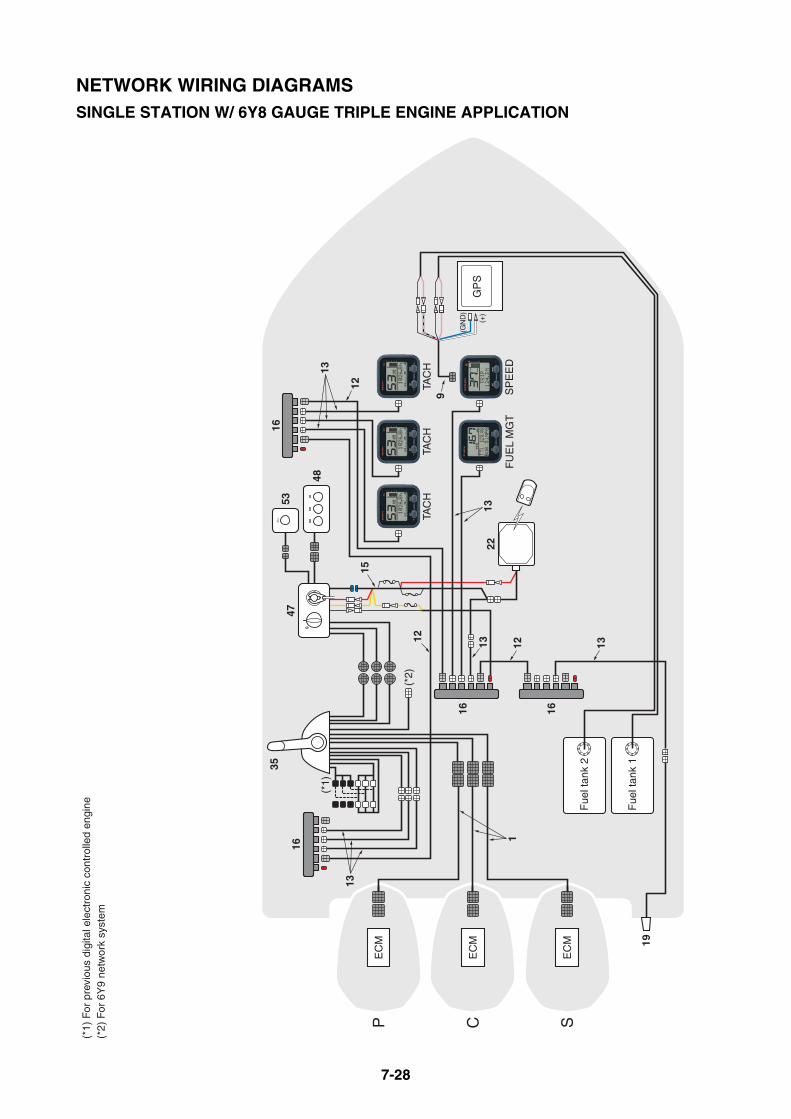
7-28
35
EC
M
EC
M
EC
MP C S
(*1)
(*2)
47
22
16 16
16
1653
48
19
1
13
12
GP
S
Fue
l tan
k 2
Fue
l tan
k 1
9 SP
EE
DF
UE
L M
GT
TAC
HTA
CH
TAC
H
13
(*1)
For
pre
viou
s di
gita
l ele
ctro
nic
cont
rolle
d en
gine
(*2)
For
6Y
9 ne
twor
k sy
stem
13
12 13
1512
13
(GN
D)
(+)
NETWORK WIRING DIAGRAMSSINGLE STATION W/ 6Y8 GAUGE TRIPLE ENGINE APPLICATION
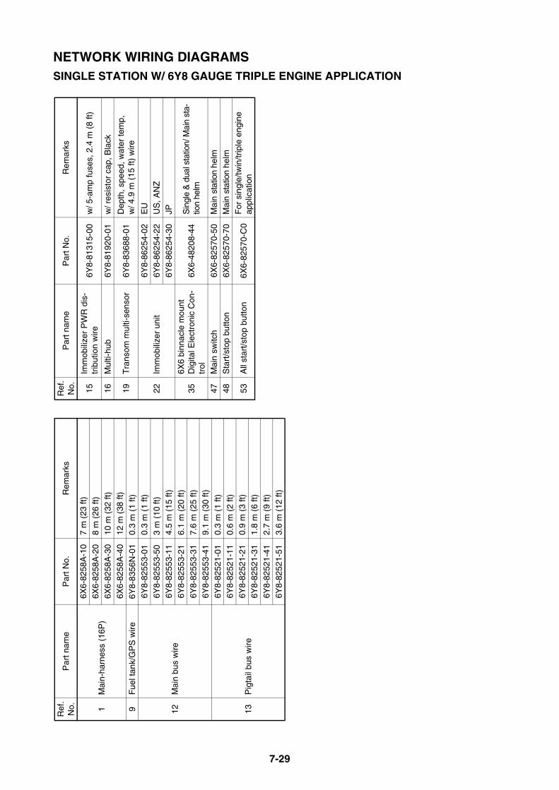
7-29
NETWORK WIRING DIAGRAMSSINGLE STATION W/ 6Y8 GAUGE TRIPLE ENGINE APPLICATION
Ref
. N
o.P
art n
ame
Par
t No.
Rem
arks
1M
ain-
harn
ess
(16P
)
6X6-
8258
A-1
07
m (
23 ft
)6X
6-82
58A
-20
8 m
(26
ft)
6X6-
8258
A-3
010
m (
32 ft
)
6X6-
8258
A-4
012
m (
38 ft
)9
Fue
l tan
k/G
PS
wire
6Y8-
8356
N-0
10.
3 m
(1
ft)
12M
ain
bus
wire
6Y8-
8255
3-01
0.3
m (
1 ft)
6Y8-
8255
3-50
3 m
(10
ft)
6Y8-
8255
3-11
4.5
m (
15 ft
)
6Y8-
8255
3-21
6.1
m (
20 ft
)
6Y8-
8255
3-31
7.6
m (
25 ft
)6Y
8-82
553-
419.
1 m
(30
ft)
13P
igta
il bu
s w
ire
6Y8-
8252
1-01
0.3
m (
1 ft)
6Y8-
8252
1-11
0.6
m (
2 ft)
6Y8-
8252
1-21
0.9
m (
3 ft)
6Y8-
8252
1-31
1.8
m (
6 ft)
6Y8-
8252
1-41
2.7
m (
9 ft)
6Y8-
8252
1-51
3.6
m (
12 ft
)
15Im
mob
ilize
r P
WR
dis
-tr
ibut
ion
wire
6Y8-
8131
5-00
w/ 5
-am
p fu
ses,
2.4
m (
8 ft)
16M
ulti-
hub
6Y8-
8192
0-01
w/ r
esis
tor
cap,
Bla
ck
19T
rans
om m
ulti-
sens
or6Y
8-83
688-
01D
epth
, spe
ed, w
ater
tem
p,
w/ 4
.9 m
(15
ft)
wire
22Im
mob
ilize
r un
it
6Y8-
8625
4-02
EU
6Y8-
8625
4-22
US
, AN
Z6Y
8-86
254-
30JP
356X
6 bi
nnac
le m
ount
D
igita
l Ele
ctro
nic
Con
-tr
ol6X
6-48
208-
44S
ingl
e &
dua
l sta
tion/
Mai
n st
a-tio
n he
lm
47M
ain
switc
h6X
6-82
570-
50M
ain
stat
ion
helm
48S
tart
/sto
p bu
tton
6X6-
8257
0-70
Mai
n st
atio
n he
lm
53A
ll st
art/s
top
butto
n6X
6-82
570-
C0
For
sin
gle/
twin
/trip
le e
ngin
e ap
plic
atio
n
Ref
. N
o.P
art n
ame
Par
t No.
Rem
arks
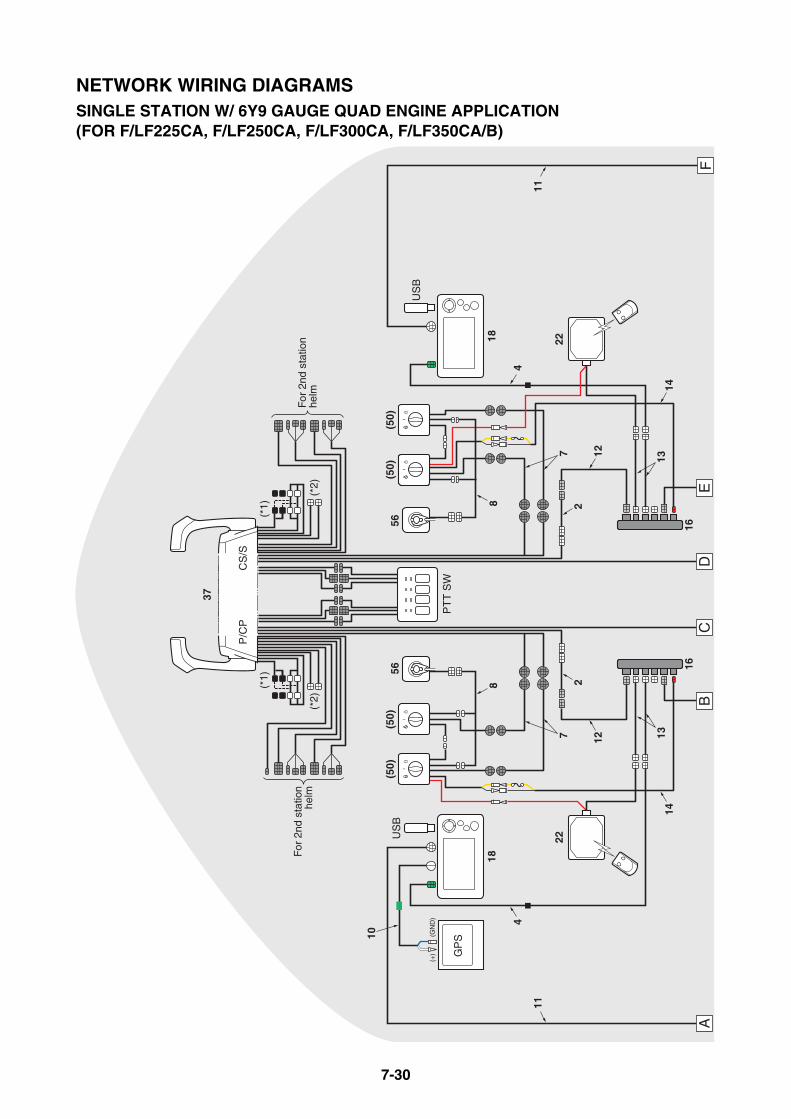
7-30
AB
CD
EF
18
US
B
16
GP
S
16
22
PT
T S
W
5656
(*1)
37
(*1)
(*2)
(*2)
P/C
PC
S/S
For
2nd
sta
tion
helm
For
2nd
sta
tion
helm
18
US
B
22
88
44
1111
(50)
(50)
(50)
(50)
10
77
22
14
1212
1413
13
(+
) (
GN
D)
NETWORK WIRING DIAGRAMSSINGLE STATION W/ 6Y9 GAUGE QUAD ENGINE APPLICATION (FOR F/LF225CA, F/LF250CA, F/LF300CA, F/LF350CA/B)
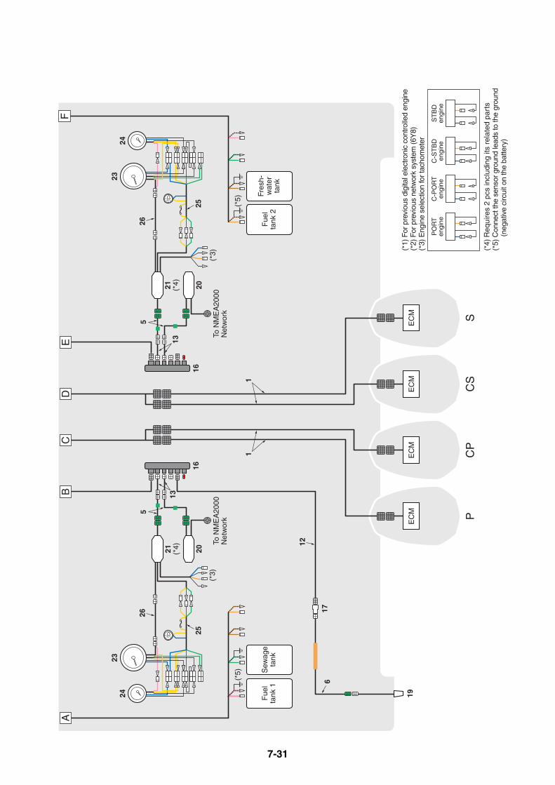
7-31
(*5)
(*5)
AB
CD
EF
(*3)
Fue
lta
nk 1
To N
ME
A20
00N
etw
ork
19
Sew
age
tank
To N
ME
A20
00N
etw
ork
1616
(*3)
EC
M PC
PC
SS
EC
ME
CM
EC
M
55
Fres
h-w
ater
tank
Fue
lta
nk 2
(*1)
For
pre
viou
s di
gita
l ele
ctro
nic
cont
rolle
d en
gine
(*2)
For
pre
viou
s ne
twor
k sy
stem
(6Y
8)(*
3) E
ngin
e se
lect
ion
for t
acho
met
er
(*4)
Req
uire
s 2
pcs
incl
udin
g its
rel
ated
par
ts(*
5) C
onne
ct th
e se
nsor
gro
und
lead
s to
the
grou
nd
(n
egat
ive
circ
uit o
n th
e ba
ttery
)
C-P
OR
Ten
gine
C-S
TB
Den
gine
PO
RT
engi
neS
TB
Den
gine
17
2423
26
25
26
25
2324
6
11
12
21 (*4) 20
21 (*4) 20
1313
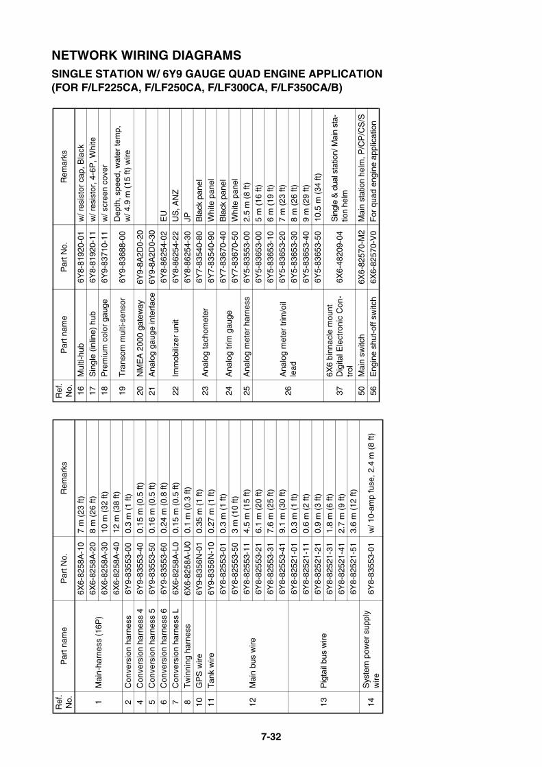
7-32
NETWORK WIRING DIAGRAMSSINGLE STATION W/ 6Y9 GAUGE QUAD ENGINE APPLICATION (FOR F/LF225CA, F/LF250CA, F/LF300CA, F/LF350CA/B)
Ref
. N
o.P
art n
ame
Par
t No.
Rem
arks
1M
ain-
harn
ess
(16P
)
6X6-
8258
A-1
07
m (
23 ft
)6X
6-82
58A
-20
8 m
(26
ft)
6X6-
8258
A-3
010
m (
32 ft
)
6X6-
8258
A-4
012
m (
38 ft
)2
Con
vers
ion
harn
ess
6Y9-
8355
3-00
0.3
m (
1 ft)
4C
onve
rsio
n ha
rnes
s 4
6Y9-
8355
3-40
0.15
m (
0.5
ft)
5C
onve
rsio
n ha
rnes
s 5
6Y9-
8355
3-50
0.16
m (
0.5
ft)6
Con
vers
ion
harn
ess
66Y
9-83
553-
600.
24 m
(0.
8 ft)
7C
onve
rsio
n ha
rnes
s L
6X6-
8258
A-L
00.
15 m
(0.
5 ft)
8T
win
ning
har
ness
6X6-
8258
A-U
00.
1 m
(0.
3 ft)
10G
PS
wire
6Y9-
8356
N-0
10.
35 m
(1
ft)
11T
ank
wire
6Y9-
8356
N-1
00.
27 m
(1
ft)
12M
ain
bus
wire
6Y8-
8255
3-01
0.3
m (
1 ft)
6Y8-
8255
3-50
3 m
(10
ft)
6Y8-
8255
3-11
4.5
m (
15 ft
)
6Y8-
8255
3-21
6.1
m (
20 ft
)
6Y8-
8255
3-31
7.6
m (
25 ft
)6Y
8-82
553-
419.
1 m
(30
ft)
13P
igta
il bu
s w
ire
6Y8-
8252
1-01
0.3
m (
1 ft)
6Y8-
8252
1-11
0.6
m (
2 ft)
6Y8-
8252
1-21
0.9
m (
3 ft)
6Y8-
8252
1-31
1.8
m (
6 ft)
6Y8-
8252
1-41
2.7
m (
9 ft)
6Y8-
8252
1-51
3.6
m (
12 ft
)
14S
yste
m p
ower
sup
ply
wire
6Y8-
8355
3-01
w/ 1
0-am
p fu
se, 2
.4 m
(8
ft)
16M
ulti-
hub
6Y8-
8192
0-01
w/ r
esis
tor
cap,
Bla
ck17
Sin
gle
(inlin
e) h
ub6Y
8-81
920-
11w
/ res
isto
r, 4
-6P
, Whi
te
18P
rem
ium
col
or g
auge
6Y9-
8371
0-11
w/ s
cree
n co
ver
19T
rans
om m
ulti-
sens
or6Y
9-83
688-
00D
epth
, spe
ed, w
ater
tem
p,
w/ 4
.9 m
(15
ft)
wire
20N
ME
A 2
000
gate
way
6Y9-
8A2D
0-20
21A
nalo
g ga
uge
inte
rfac
e6Y
9-8A
2D0-
30
22Im
mob
ilize
r un
it
6Y8-
8625
4-02
EU
6Y8-
8625
4-22
US
, AN
Z
6Y8-
8625
4-30
JP
23A
nalo
g ta
chom
eter
6Y7-
8354
0-80
Bla
ck p
anel
6Y7-
8354
0-90
Whi
te p
anel
24A
nalo
g tr
im g
auge
6Y7-
8367
0-40
Bla
ck p
anel
6Y7-
8367
0-50
Whi
te p
anel
25A
nalo
g m
eter
har
ness
6Y5-
8355
3-00
2.5
m (
8 ft)
26A
nalo
g m
eter
trim
/oil
lead
6Y5-
8365
3-00
5 m
(16
ft)
6Y5-
8365
3-10
6 m
(19
ft)
6Y5-
8365
3-20
7 m
(23
ft)
6Y5-
8365
3-30
8 m
(26
ft)
6Y5-
8365
3-40
9 m
(29
ft)
6Y5-
8365
3-50
10.5
m (
34 ft
)
376X
6 bi
nnac
le m
ount
D
igita
l Ele
ctro
nic
Con
-tr
ol6X
6-48
209-
04S
ingl
e &
dua
l sta
tion/
Mai
n st
a-tio
n he
lm
50M
ain
switc
h6X
6-82
570-
M2
Mai
n st
atio
n he
lm, P
/CP
/CS
/S
56E
ngin
e sh
ut-o
ff sw
itch
6X6-
8257
0-V
0F
or q
uad
engi
ne a
pplic
atio
n
Ref
. N
o.P
art n
ame
Par
t No.
Rem
arks

MEMO
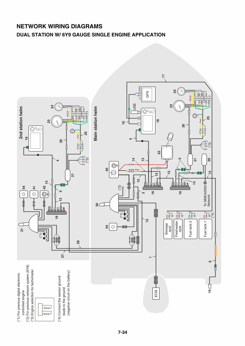
7-34
(*4)
18
Fue
l tan
k 2
Fue
l tan
k 1
US
B
21 20
GP
S
To N
ME
A20
00N
etw
ork
(*3)
Fres
hwat
erta
nk
Sew
age
tank
31
21
(*3)
18
(*1)
For
pre
viou
s di
gita
l ele
ctro
nic
co
ntro
lled
engi
ne(*
2) F
or p
revi
ous
netw
ork
syst
em (
6Y8)
(*3)
Eng
ine
sele
ctio
n fo
r ta
chom
eter
(*4)
Con
nect
the
sens
or g
roun
d
lead
s to
the
grou
nd
(n
egat
ive
circ
uit o
n th
e ba
ttery
)
30
40
EC
M
(*2)
(*1)
22
(*1)
54
16
16 16
527
28
54 41 4223
24
264
3
2324
26
256
19
1
25
13
13
12
1214
13
13
4
11
5
12
13
13
10
(+
) (
GN
D)
2nd
sta
tio
n h
elm
Mai
n s
tati
on
hel
m
NETWORK WIRING DIAGRAMSDUAL STATION W/ 6Y9 GAUGE SINGLE ENGINE APPLICATION

7-35
NETWORK WIRING DIAGRAMSDUAL STATION W/ 6Y9 GAUGE SINGLE ENGINE APPLICATION
Ref
. N
o.P
art n
ame
Par
t No.
Rem
arks
1M
ain-
harn
ess
(16P
)
6X6-
8258
A-1
07
m (
23 ft
)6X
6-82
58A
-20
8 m
(26
ft)
6X6-
8258
A-3
010
m (
32 ft
)
6X6-
8258
A-4
012
m (
38 ft
)3
Con
vers
ion
harn
ess
16Y
9-83
553-
100.
3 m
(1
ft)
4C
onve
rsio
n ha
rnes
s 4
6Y9-
8355
3-40
0.15
m (
0.5
ft)
5C
onve
rsio
n ha
rnes
s 5
6Y9-
8355
3-50
0.16
m (
0.5
ft)6
Con
vers
ion
harn
ess
66Y
9-83
553-
600.
24 m
(0.
8 ft)
10G
PS
wire
6Y9-
8356
N-0
10.
35 m
(1.
1 ft)
11T
ank
wire
6Y9-
8356
N-1
00.
27 m
(0.
9 ft)
12M
ain
bus
wire
6Y8-
8255
3-01
0.3
m (
1 ft)
6Y8-
8255
3-50
3 m
(10
ft)
6Y8-
8255
3-11
4.5
m (
15 ft
)
6Y8-
8255
3-21
6.1
m (
20 ft
)6Y
8-82
553-
317.
6 m
(25
ft)
6Y8-
8255
3-41
9.1
m (
30 ft
)
13P
igta
il bu
s w
ire
6Y8-
8252
1-01
0.3
m (
1 ft)
6Y8-
8252
1-11
0.6
m (
2 ft)
6Y8-
8252
1-21
0.9
m (
3 ft)
6Y8-
8252
1-31
1.8
m (
6 ft)
6Y8-
8252
1-41
2.7
m (
9 ft)
6Y8-
8252
1-51
3.6
m (
12 ft
)
14S
yste
m p
ower
sup
ply
wire
6Y8-
8355
3-01
w/ 1
0-am
p fu
se, 2
.4 m
(8
ft)
16M
ulti-
hub
6Y8-
8192
0-01
w/ r
esis
tor
cap,
Bla
ck
18P
rem
ium
col
or g
auge
6Y9-
8371
0-01
w/ s
cree
n co
ver
19T
rans
om m
ulti-
sens
or6Y
9-83
688-
00D
epth
, spe
ed, w
ater
tem
p,
w/ 4
.9 m
(15
ft)
wire
20N
ME
A 2
000
gate
way
6Y9-
8A2D
0-20
21A
nalo
g ga
uge
inte
rfac
e6Y
9-8A
2D0-
30
22Im
mob
ilize
r un
it6Y
8-86
254-
02E
U6Y
8-86
254-
22U
S, A
NZ
6Y8-
8625
4-30
JP
23A
nalo
g ta
chom
eter
6Y7-
8354
0-80
Bla
ck p
anel
6Y7-
8354
0-90
Whi
te p
anel
24A
nalo
g tr
im g
auge
6Y7-
8367
0-40
Bla
ck p
anel
6Y7-
8367
0-50
Whi
te p
anel
25A
nalo
g m
eter
har
ness
6Y5-
8355
3-00
2.5
m (
8 ft)
26A
nalo
g m
eter
trim
/oil
lead
6Y5-
8365
3-00
5 m
(16
ft)
6Y5-
8365
3-10
6 m
(19
ft)
6Y5-
8365
3-20
7 m
(23
ft)
6Y5-
8365
3-30
8 m
(26
ft)
6Y5-
8365
3-40
9 m
(29
ft)
6Y5-
8365
3-50
10.5
m (
34 ft
)
272n
d st
atio
n he
lm h
ar-
ness
(2
-12P
)
6X6-
8258
A-B
15
m (
16 ft
)
6X6-
8258
A-D
18
m (
26 ft
)
6X6-
8258
A-F
112
m (
38 ft
)
282n
d st
atio
n he
lm h
ar-
ness
(3
/4/6
P)
6X6-
8258
A-G
15
m (
16 ft
)
6X6-
8258
A-H
18
m (
26 ft
)
6X6-
8258
A-J
112
m (
38 ft
)
306X
6 bi
nnac
le m
ount
D
igita
l Ele
ctro
nic
Con
-tr
ol6X
6-48
205-
43D
ual s
tatio
n/M
ain
stat
ion
helm
316X
6 bi
nnac
le m
ount
D
igita
l Ele
ctro
nic
Con
-tr
ol6X
6-48
205-
53D
ual s
tatio
n/2n
d st
atio
n he
lm
40M
ain
switc
h6X
6-82
570-
31F
or 6
X6
binn
acle
mou
nt D
igi-
tal E
lect
roni
c C
ontr
ol, M
ain
stat
ion
helm
41S
tart
/sto
p bu
tton
6X6-
8257
0-80
2nd
stat
ion
helm
42E
ngin
e sh
ut-o
ff sw
itch
6X6-
8257
0-90
2nd
stat
ion
helm
54S
tatio
n se
lect
or s
witc
h6X
6-82
570-
B0
For
dua
l sta
tion,
sin
gle/
twin
/tr
iple
eng
ine
appl
icat
ion
Ref
. N
o.P
art n
ame
Par
t No.
Rem
arks
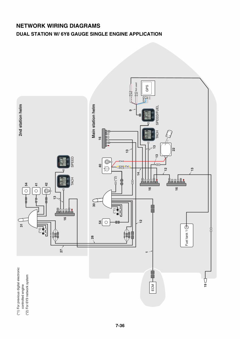
7-36
Fue
l tan
k 1
GP
S
31(*
1) F
or p
revi
ous
digi
tal e
lect
roni
c
cont
rolle
d en
gine
(*2)
For
6Y
9 ne
twor
k sy
stem
30
54
16
16
27
28
54
SP
EE
DTA
CH
SP
EE
D/F
UE
LTA
CH
16
EC
M
1
19
(*2)
13
13
1412
(*1)
41 42
(*1)
4016
22
9
1313
1312
2nd
sta
tio
n h
elm
Mai
n s
tati
on
hel
m
(GN
D)
(+)
Not
use
d
NETWORK WIRING DIAGRAMSDUAL STATION W/ 6Y8 GAUGE SINGLE ENGINE APPLICATION

7-37
NETWORK WIRING DIAGRAMSDUAL STATION W/ 6Y8 GAUGE SINGLE ENGINE APPLICATION
Ref
. N
o.P
art n
ame
Par
t No.
Rem
arks
1M
ain-
harn
ess
(16P
)
6X6-
8258
A-1
07
m (
23 ft
)6X
6-82
58A
-20
8 m
(26
ft)
6X6-
8258
A-3
010
m (
32 ft
)
6X6-
8258
A-4
012
m (
38 ft
)9
Fue
l tan
k/G
PS
wire
6Y8-
8356
N-0
10.
3 m
(1
ft)
12M
ain
bus
wire
6Y8-
8255
3-01
0.3
m (
1 ft)
6Y8-
8255
3-50
3 m
(10
ft)
6Y8-
8255
3-11
4.6
m (
15 ft
)
6Y8-
8255
3-21
6.1
m (
20 ft
)
6Y8-
8255
3-31
7.6
m (
25 ft
)6Y
8-82
553-
419.
1 m
(30
ft)
13P
igta
il bu
s w
ire
6Y8-
8252
1-01
0.3
m (
1 ft)
6Y8-
8252
1-11
0.6
m (
2 ft)
6Y8-
8252
1-21
0.9
m (
3 ft)
6Y8-
8252
1-31
1.8
m (
6 ft)
6Y8-
8252
1-41
2.7
m (
9 ft)
6Y8-
8252
1-51
3.6
m (
12 ft
)
14S
yste
m p
ower
sup
ply
wire
6Y8-
8355
3-01
w/ 1
0-am
p fu
se, 2
.4 m
(8
ft)
16M
ulti-
hub
6Y8-
8192
0-01
w/ r
esis
tor
cap,
Bla
ck
19T
rans
om m
ulti-
sens
or6Y
8-83
688-
01D
epth
, spe
ed, w
ater
tem
p,
w/ 4
.9 m
(15
ft)
wire
22Im
mob
ilize
r un
it6Y
8-86
254-
02E
U6Y
8-86
254-
22U
S, A
NZ
6Y8-
8625
4-30
JP
272n
d he
lm h
arne
ss
(2-1
2P)
6X6-
8258
A-B
15
m (
16 ft
)6X
6-82
58A
-D1
8 m
(26
ft)
6X6-
8258
A-F
112
m (
38 ft
)
282n
d he
lm h
arne
ss
(3/4
/6P
)
6X6-
8258
A-G
15
m (
16 ft
)6X
6-82
58A
-H1
8 m
(26
ft)
6X6-
8258
A-J
112
m (
38 ft
)
306X
6 bi
nnac
le m
ount
D
igita
l Ele
ctro
nic
Con
-tr
ol6X
6-48
205-
44D
ual s
tatio
n/M
ain
stat
ion
helm
316X
6 bi
nnac
le m
ount
D
igita
l Ele
ctro
nic
Con
-tr
ol6X
6-48
205-
53D
ual s
tatio
n/2n
d st
atio
n he
lm
40M
ain
switc
h6X
6-82
570-
316X
6 bi
nnac
le m
ount
Dig
ital
Ele
ctro
nic
Con
trol
, Mai
n st
a-tio
n he
lm
41S
tart
/sto
p bu
tton
6X6-
8257
0-80
2nd
stat
ion
helm
42E
ngin
e sh
ut-o
ff sw
itch
6X6-
8257
0-90
2nd
stat
ion
helm
54S
tatio
n se
lect
or s
witc
h6X
6-82
570-
B0
For
dua
l sta
tion,
sin
gle/
twin
/tr
iple
eng
ine
appl
icat
ion
Ref
. N
o.P
art n
ame
Par
t No.
Rem
arks

7-38
(*5)
33
44
18
Fue
l tan
k 2
Fue
l tan
k 1
US
B
21 (*4) 20
GP
S
To N
ME
A20
00N
etw
ork
(*3)
Fres
hwat
erta
nk
Sew
age
tank
22
21 (*4)
(*3)
54
27 28
EC
M
EC
MP S
(*1)
(*1)
(*1)
(*2)
PO
RT
eng
ine
ST
BD
eng
ine
(*1)
For
pre
viou
s di
gita
l ele
ctro
nic
co
ntro
lled
engi
ne(*
2) F
or p
revi
ous
netw
ork
syst
em (
6Y8)
(*3)
Eng
ine
sele
ctio
n fo
r ta
chom
eter
(*4)
Req
uire
s 2
pcs
incl
udin
g its
rela
ted
part
s(*
5) C
onne
ct th
e se
nsor
gro
und
le
ads
to th
e gr
ound
(neg
ativ
e ci
rcui
t on
the
batte
ry)
34
16
1616
54
46
42
18
2324
26
25
45
53
45
2324
25
26
3
619
1
13
13
12
12
13
4
11
5
12
13
13
10
15 13
2nd
sta
tio
n h
elm
Mai
n s
tati
on
hel
m
(+
) (
GN
D)
NETWORK WIRING DIAGRAMSDUAL STATION W/ 6Y9 GAUGE TWIN ENGINE APPLICATION
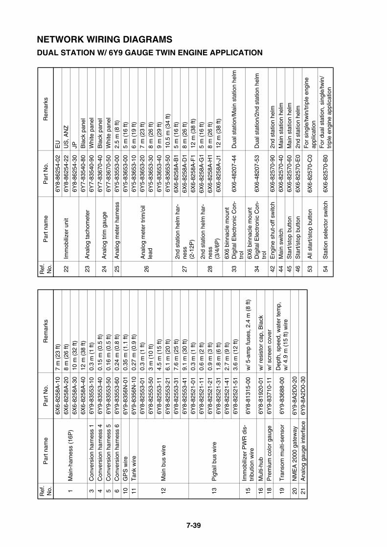
7-39
NETWORK WIRING DIAGRAMSDUAL STATION W/ 6Y9 GAUGE TWIN ENGINE APPLICATION
Ref
. N
o.P
art n
ame
Par
t No.
Rem
arks
1M
ain-
harn
ess
(16P
)
6X6-
8258
A-1
07
m (
23 ft
)6X
6-82
58A
-20
8 m
(26
ft)
6X6-
8258
A-3
010
m (
32 ft
)
6X6-
8258
A-4
012
m (
38 ft
)3
Con
vers
ion
harn
ess
16Y
9-83
553-
100.
3 m
(1
ft)
4C
onve
rsio
n ha
rnes
s 4
6Y9-
8355
3-40
0.15
m (
0.5
ft)
5C
onve
rsio
n ha
rnes
s 5
6Y9-
8355
3-50
0.16
m (
0.5
ft)6
Con
vers
ion
harn
ess
66Y
9-83
553-
600.
24 m
(0.
8 ft)
10G
PS
wire
6Y9-
8356
N-0
10.
35 m
(1.
1 ft)
11T
ank
wire
6Y9-
8356
N-1
00.
27 m
(0.
9 ft)
12M
ain
bus
wire
6Y8-
8255
3-01
0.3
m (
1 ft)
6Y8-
8255
3-50
3 m
(10
ft)
6Y8-
8255
3-11
4.5
m (
15 ft
)
6Y8-
8255
3-21
6.1
m (
20 ft
)6Y
8-82
553-
317.
6 m
(25
ft)
6Y8-
8255
3-41
9.1
m (
30 ft
)
13P
igta
il bu
s w
ire
6Y8-
8252
1-01
0.3
m (
1 ft)
6Y8-
8252
1-11
0.6
m (
2 ft)
6Y8-
8252
1-21
0.9
m (
3 ft)
6Y8-
8252
1-31
1.8
m (
6 ft)
6Y8-
8252
1-41
2.7
m (
9 ft)
6Y8-
8252
1-51
3.6
m (
12 ft
)
15Im
mob
ilize
r P
WR
dis
-tr
ibut
ion
wire
6Y8-
8131
5-00
w/ 5
-am
p fu
ses,
2.4
m (
8 ft)
16M
ulti-
hub
6Y8-
8192
0-01
w/ r
esis
tor
cap,
Bla
ck
18P
rem
ium
col
or g
auge
6Y9-
8371
0-11
w/ s
cree
n co
ver
19T
rans
om m
ulti-
sens
or6Y
9-83
688-
00D
epth
, spe
ed, w
ater
tem
p,
w/ 4
.9 m
(15
ft)
wire
20N
ME
A 2
000
gate
way
6Y9-
8A2D
0-20
21A
nalo
g ga
uge
inte
rfac
e6Y
9-8A
2D0-
30
22Im
mob
ilize
r un
it6Y
8-86
254-
02E
U6Y
8-86
254-
22U
S, A
NZ
6Y8-
8625
4-30
JP
23A
nalo
g ta
chom
eter
6Y7-
8354
0-80
Bla
ck p
anel
6Y7-
8354
0-90
Whi
te p
anel
24A
nalo
g tr
im g
auge
6Y7-
8367
0-40
Bla
ck p
anel
6Y7-
8367
0-50
Whi
te p
anel
25A
nalo
g m
eter
har
ness
6Y5-
8355
3-00
2.5
m (
8 ft)
26A
nalo
g m
eter
trim
/oil
lead
6Y5-
8365
3-00
5 m
(16
ft)
6Y5-
8365
3-10
6 m
(19
ft)
6Y5-
8365
3-20
7 m
(23
ft)
6Y5-
8365
3-30
8 m
(26
ft)
6Y5-
8365
3-40
9 m
(29
ft)
6Y5-
8365
3-50
10.5
m (
34 ft
)
272n
d st
atio
n he
lm h
ar-
ness
(2
-12P
)
6X6-
8258
A-B
15
m (
16 ft
)
6X6-
8258
A-D
18
m (
26 ft
)
6X6-
8258
A-F
112
m (
38 ft
)
282n
d st
atio
n he
lm h
ar-
ness
(3
/4/6
P)
6X6-
8258
A-G
15
m (
16 ft
)
6X6-
8258
A-H
18
m (
26 ft
)
6X6-
8258
A-J
112
m (
38 ft
)
336X
6 bi
nnac
le m
ount
D
igita
l Ele
ctro
nic
Con
-tr
ol6X
6-48
207-
44D
ual s
tatio
n/M
ain
stat
ion
helm
346X
6 bi
nnac
le m
ount
D
igita
l Ele
ctro
nic
Con
-tr
ol6X
6-48
207-
53D
ual s
tatio
n/2n
d st
atio
n he
lm
42E
ngin
e sh
ut-o
ff sw
itch
6X6-
8257
0-90
2nd
stat
ion
helm
44M
ain
switc
h6X
6-82
570-
40M
ain
stat
ion
helm
45S
tart
/sto
p bu
tton
6X6-
8257
0-60
Mai
n st
atio
n he
lm
46S
tart
/sto
p bu
tton
6X6-
8257
0-E
02n
d st
atio
n he
lm
53A
ll st
art/s
top
butto
n6X
6-82
570-
C0
For
sin
gle/
twin
/trip
le e
ngin
e ap
plic
atio
n
54S
tatio
n se
lect
or s
witc
h6X
6-82
570-
B0
For
dua
l sta
tion,
sin
gle/
twin
/tr
iple
eng
ine
appl
icat
ion
Ref
. N
o.P
art n
ame
Par
t No.
Rem
arks
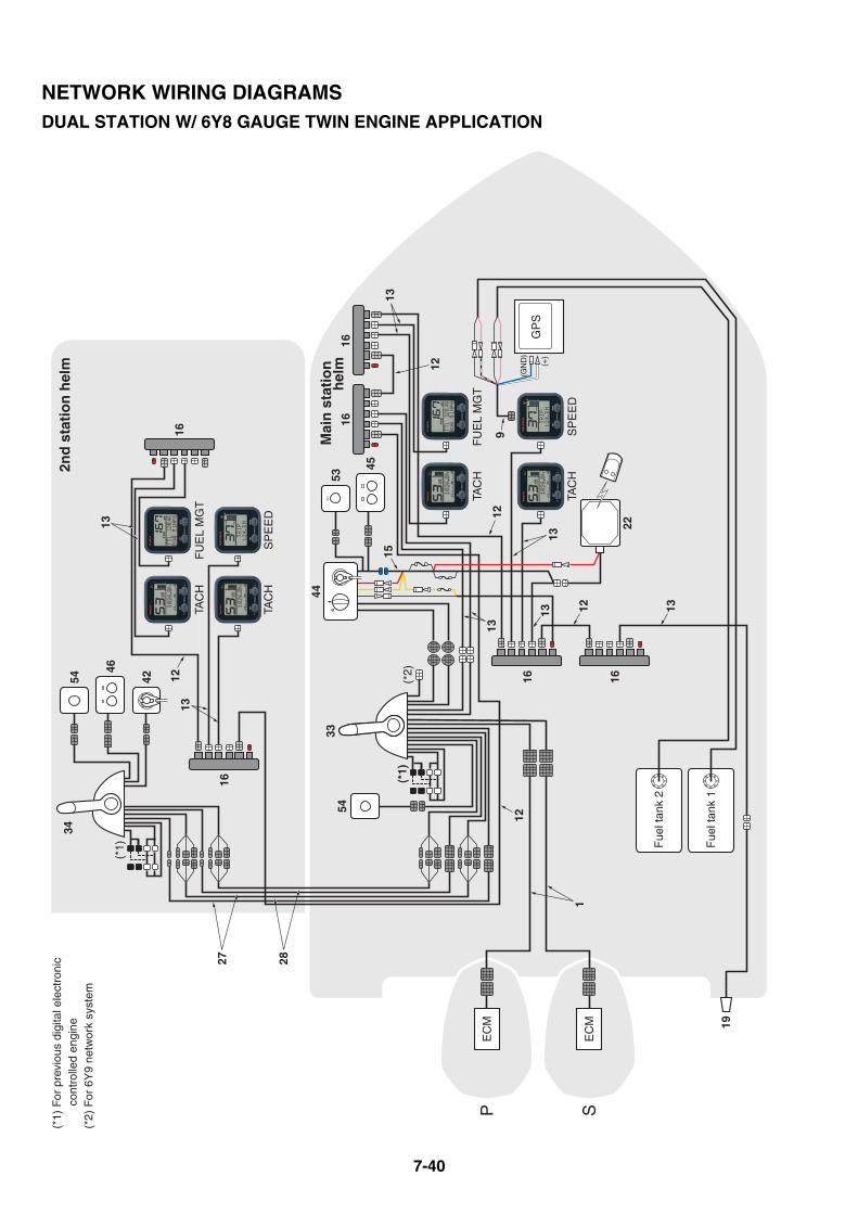
7-40
3354
27 28
EC
M
EC
MP S
(*2)
34
16
1616
16
16
1
19
TAC
H
SP
EE
D
FU
EL
MG
T
TAC
H
GP
S
Fue
l tan
k 1
Fue
l tan
k 2
TAC
H
SP
EE
D
FU
EL
MG
T
TAC
H
16
9
12
1213
13
13
12
(*1)
54
46
42
(*1)
(*1)
44
53
45
22
1513
(*1)
For
pre
viou
s di
gita
l ele
ctro
nic
co
ntro
lled
engi
ne(*
2) F
or 6
Y9
netw
ork
syst
em
1313
12
13
12
2nd
sta
tio
n h
elm
Mai
n s
tati
on
h
elm
(GN
D)
(+)
NETWORK WIRING DIAGRAMSDUAL STATION W/ 6Y8 GAUGE TWIN ENGINE APPLICATION
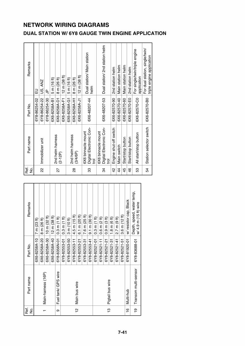
7-41
NETWORK WIRING DIAGRAMSDUAL STATION W/ 6Y8 GAUGE TWIN ENGINE APPLICATION
Ref
. N
o.P
art n
ame
Par
t No.
Rem
arks
1M
ain-
harn
ess
(16P
)
6X6-
8258
A-1
07
m (
23 ft
)6X
6-82
58A
-20
8 m
(26
ft)
6X6-
8258
A-3
010
m (
32 ft
)
6X6-
8258
A-4
012
m (
38 ft
)9
Fue
l tan
k/ G
PS
wire
6Y8-
8356
N-0
10.
3 m
(1
ft)
12M
ain
bus
wire
6Y8-
8255
3-01
0.3
m (
1 ft)
6Y8-
8255
3-50
3 m
(10
ft)
6Y8-
8255
3-11
4.5
m (
15 ft
)
6Y8-
8255
3-21
6.1
m (
20 ft
)
6Y8-
8255
3-31
7.6
m (
25 ft
)6Y
8-82
553-
419.
1 m
(30
ft)
13P
igta
il bu
s w
ire
6Y8-
8252
1-01
0.3
m (
1 ft)
6Y8-
8252
1-11
0.6
m (
2 ft)
6Y8-
8252
1-21
0.9
m (
3 ft)
6Y8-
8252
1-31
1.8
m (
6 ft)
6Y8-
8252
1-41
2.7
m (
9 ft)
6Y8-
8252
1-51
3.6
m (
12 ft
)16
Mul
ti-hu
b6Y
8-81
920-
01w
/ res
isto
r ca
p, B
lack
19T
rans
om m
ulti-
sens
or6Y
8-83
688-
01D
epth
, spe
ed, w
ater
tem
p,
w/ 4
.9 m
(15
ft)
wire
22Im
mob
ilize
r un
it6Y
8-86
254-
02E
U6Y
8-86
254-
22U
S, A
NZ
6Y8-
8625
4-30
JP
272n
d he
lm h
arne
ss
(2-1
2P)
6X6-
8258
A-B
15
m (
16 ft
)6X
6-82
58A
-D1
8 m
(26
ft)
6X6-
8258
A-F
112
m (
38 ft
)
282n
d he
lm h
arne
ss
(3/4
/6P
)
6X6-
8258
A-G
15
m (
16 ft
)6X
6-82
58A
-H1
8 m
(26
ft)
6X6-
8258
A-J
112
m (
38 ft
)
336X
6 bi
nnac
le m
ount
D
igita
l Ele
ctro
nic
Con
-tr
ol6X
6-48
207-
44D
ual s
tatio
n/ M
ain
stat
ion
helm
346X
6 bi
nnac
le m
ount
D
igita
l Ele
ctro
nic
Con
-tr
ol6X
6-48
207-
53D
ual s
tatio
n/ 2
nd s
tatio
n he
lm
42E
ngin
e sh
ut-o
ff sw
itch
6X6-
8257
0-90
2nd
stat
ion
helm
44M
ain
switc
h6X
6-82
570-
40M
ain
stat
ion
helm
45S
tart
/sto
p bu
tton
6X6-
8257
0-60
Mai
n st
atio
n he
lm
46S
tart
/sto
p bu
tton
6X6-
8257
0-E
02n
d st
atio
n he
lm
53A
ll st
art/s
top
butto
n6X
6-82
570-
C0
For
sin
gle/
twin
/trip
le e
ngin
e ap
plic
atio
n
54S
tatio
n se
lect
or s
witc
h6X
6-82
570-
B0
For
dua
l sta
tion,
sin
gle/
twin
/tr
iple
eng
ine
appl
icat
ion
Ref
. N
o.P
art n
ame
Par
t No.
Rem
arks
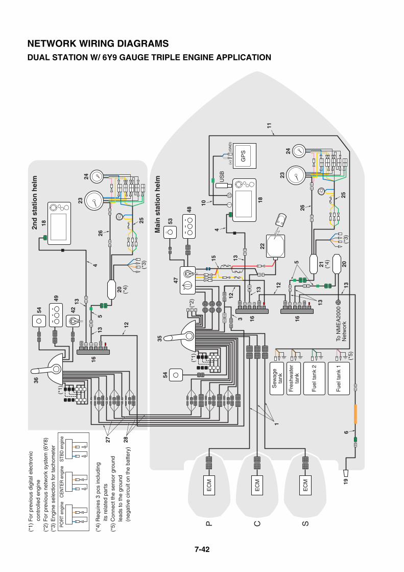
7-42
(*5)
35
EC
M
EC
M
EC
MP C S
(*1)
47
18
Fue
l tan
k 2
Fue
l tan
k 1
US
B
21 (*4) 20
GP
S
To N
ME
A20
00N
etw
ork
(*3)
Fres
hwat
erta
nk
Sew
age
tank
22
(*2)
20 (*4)
(*3)
54
(*1)
(*1)
For
pre
viou
s di
gita
l ele
ctro
nic
co
ntro
lled
engi
ne(*
2) F
or p
revi
ous
netw
ork
syst
em (
6Y8)
(*3)
Eng
ine
sele
ctio
n fo
r ta
chom
eter
(*4)
Req
uire
s 3
pcs
incl
udin
g
its r
elat
ed p
arts
(*5)
Con
nect
the
sens
or g
roun
d
lead
s to
the
grou
nd
(n
egat
ive
circ
uit o
n th
e ba
ttery
)
CE
NTE
R e
ngin
eP
OR
T en
gine
STB
D e
ngin
e
36
16
1616
54
49
42
18
2324
26
25
45
53
48
2324
26
256
19
3
1
13
13
12
12
4
11
5
12
13
13
10
15 13
13
27 28
2nd
sta
tio
n h
elm
Mai
n s
tati
on
hel
m
(+
) (
GN
D)
NETWORK WIRING DIAGRAMSDUAL STATION W/ 6Y9 GAUGE TRIPLE ENGINE APPLICATION
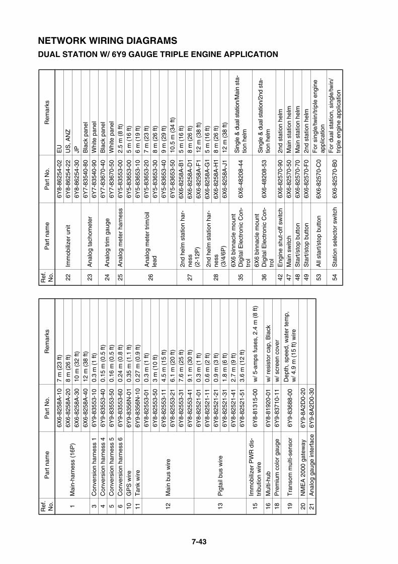
7-43
NETWORK WIRING DIAGRAMSDUAL STATION W/ 6Y9 GAUGE TRIPLE ENGINE APPLICATION
Ref
. N
o.P
art n
ame
Par
t No.
Rem
arks
1M
ain-
harn
ess
(16P
)
6X6-
8258
A-1
07
m (
23 ft
)6X
6-82
58A
-20
8 m
(26
ft)
6X6-
8258
A-3
010
m (
32 ft
)
6X6-
8258
A-4
012
m (
38 ft
)3
Con
vers
ion
harn
ess
16Y
9-83
553-
100.
3 m
(1
ft)
4C
onve
rsio
n ha
rnes
s 4
6Y9-
8355
3-40
0.15
m (
0.5
ft)
5C
onve
rsio
n ha
rnes
s 5
6Y9-
8355
3-50
0.16
m (
0.5
ft)6
Con
vers
ion
harn
ess
66Y
9-83
553-
600.
24 m
(0.
8 ft)
10G
PS
wire
6Y9-
8356
N-0
10.
35 m
(1.
1 ft)
11T
ank
wire
6Y9-
8356
N-1
00.
27 m
(0.
9 ft)
12M
ain
bus
wire
6Y8-
8255
3-01
0.3
m (
1 ft)
6Y8-
8255
3-50
3 m
(10
ft)
6Y8-
8255
3-11
4.5
m (
15 ft
)
6Y8-
8255
3-21
6.1
m (
20 ft
)6Y
8-82
553-
317.
6 m
(25
ft)
6Y8-
8255
3-41
9.1
m (
30 ft
)
13P
igta
il bu
s w
ire
6Y8-
8252
1-01
0.3
m (
1 ft)
6Y8-
8252
1-11
0.6
m (
2 ft)
6Y8-
8252
1-21
0.9
m (
3 ft)
6Y8-
8252
1-31
1.8
m (
6 ft)
6Y8-
8252
1-41
2.7
m (
9 ft)
6Y8-
8252
1-51
3.6
m (
12 ft
)
15Im
mob
ilize
r P
WR
dis
-tr
ibut
ion
wire
6Y8-
8131
5-00
w/ 5
-am
ps fu
ses,
2.4
m (
8 ft)
16M
ulti-
hub
6Y8-
8192
0-01
w/ r
esis
tor
cap,
Bla
ck
18P
rem
ium
col
or g
auge
6Y9-
8371
0-11
w/ s
cree
n co
ver
19T
rans
om m
ulti-
sens
or6Y
9-83
688-
00D
epth
, spe
ed, w
ater
tem
p,
w/ 4
.9 m
(15
ft)
wire
20N
ME
A 2
000
gate
way
6Y9-
8A2D
0-20
21A
nalo
g ga
uge
inte
rfac
e6Y
9-8A
2D0-
30
22Im
mob
ilize
r un
it6Y
8-86
254-
02E
U6Y
8-86
254-
22U
S, A
NZ
6Y8-
8625
4-30
JP
23A
nalo
g ta
chom
eter
6Y7-
8354
0-80
Bla
ck p
anel
6Y7-
8354
0-90
Whi
te p
anel
24A
nalo
g tr
im g
auge
6Y7-
8367
0-40
Bla
ck p
anel
6Y7-
8367
0-50
Whi
te p
anel
25A
nalo
g m
eter
har
ness
6Y5-
8355
3-00
2.5
m (
8 ft)
26A
nalo
g m
eter
trim
/oil
lead
6Y5-
8365
3-00
5 m
(16
ft)
6Y5-
8365
3-10
6 m
(19
ft)
6Y5-
8365
3-20
7 m
(23
ft)
6Y5-
8365
3-30
8 m
(26
ft)
6Y5-
8365
3-40
9 m
(29
ft)
6Y5-
8365
3-50
10.5
m (
34 ft
)
272n
d he
lm s
tatio
n ha
r-ne
ss
(2-1
2P)
6X6-
8258
A-B
15
m (
16 ft
)
6X6-
8258
A-D
18
m (
26 ft
)
6X6-
8258
A-F
112
m (
38 ft
)
282n
d he
lm s
tatio
n ha
r-ne
ss
(3/4
/6P
)
6X6-
8258
A-G
15
m (
16 ft
)
6X6-
8258
A-H
18
m (
26 ft
)
6X6-
8258
A-J
112
m (
38 ft
)
356X
6 bi
nnac
le m
ount
D
igita
l Ele
ctro
nic
Con
-tr
ol6X
6-48
208-
44S
ingl
e &
dua
l sta
tion/
Mai
n st
a-tio
n he
lm
366X
6 bi
nnac
le m
ount
D
igita
l Ele
ctro
nic
Con
-tr
ol6X
6-48
208-
53S
ingl
e &
dua
l sta
tion/
2nd
sta-
tion
helm
42E
ngin
e sh
ut-o
ff sw
itch
6X6-
8257
0-90
2nd
stat
ion
helm
47M
ain
switc
h6X
6-82
570-
50M
ain
stat
ion
helm
48S
tart
/sto
p bu
tton
6X6-
8257
0-70
Mai
n st
atio
n he
lm
49S
tart
/sto
p bu
tton
6X6-
8257
0-F
02n
d st
atio
n he
lm
53A
ll st
art/s
top
butto
n6X
6-82
570-
C0
For
sin
gle/
twin
/trip
le e
ngin
e ap
plic
atio
n
54S
tatio
n se
lect
or s
witc
h6X
6-82
570-
B0
For
dua
l sta
tion,
sin
gle/
twin
/tr
iple
eng
ine
appl
icat
ion
Ref
. N
o.P
art n
ame
Par
t No.
Rem
arks
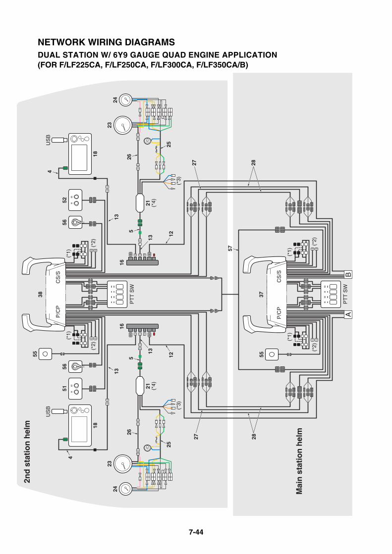
7-44
AB
(*1)
37
(*1)
(*2)
(*1)
(*2)
38
(*3)
21 (*4)
21 (*4)
(*3)
1616
18
55
(*2)
55
US
B
(*1)
(*2)
18
US
B
2827
PT
T S
W
PT
T S
W
5156
5256
P/C
PC
S/S
P/C
PC
S/S
4
4
2423
26
25
55
26
25
27 28
2423
1313
1313
1212
57
2nd
sta
tio
n h
elm
Mai
n s
tati
on
hel
m
NETWORK WIRING DIAGRAMSDUAL STATION W/ 6Y9 GAUGE QUAD ENGINE APPLICATION (FOR F/LF225CA, F/LF250CA, F/LF300CA, F/LF350CA/B)

7-45
(*5)
(*5)
AB
18
US
B
21 (*4) 20
16
GP
S
22
(*3)
Fue
lta
nk 1
To N
ME
A20
00N
etw
ork
19
Sew
age
tank
16
EC
M PC
PC
SS
EC
ME
CM
EC
M
5
Fres
h-w
ater
tank
Fue
lta
nk 2
7
5656
21 (*4) 20
16
(*3)
To N
ME
A20
00N
etw
ork
16
5
7
18
US
B
17
22
88
33
2423
26
25
26
25
2423
4
6
4
1111
11
1313
1212
14
1212
1313
12
(50)
(50)
(50)
(50)
10
14
(*1)
For
pre
viou
s di
gita
l ele
ctro
nic
cont
rolle
d en
gine
(*2)
For
pre
viou
s ne
twor
k sy
stem
(6Y
8)(*
3) E
ngin
e se
lect
ion
for
tach
omet
er
C-P
OR
T en
gine
C-S
TBD
eng
ine
PO
RT
engi
neS
TBD
eng
ine
(*4)
Req
uire
s 2
pcs
incl
udin
g its
rel
ated
par
ts(*
5) C
onne
ct th
e se
nsor
gro
und
lead
s to
the
grou
nd
(n
egat
ive
circ
uit o
n th
e ba
ttery
)
(+
) (
GN
D)

7-46
NETWORK WIRING DIAGRAMSDUAL STATION W/ 6Y9 GAUGE QUAD ENGINE APPLICATION (FOR F/LF225CA, F/LF250CA, F/LF300CA, F/LF350CA/B)
Ref
. N
o.P
art n
ame
Par
t No.
Rem
arks
1M
ain-
harn
ess
(16P
)
6X6-
8258
A-1
07
m (
23 ft
)6X
6-82
58A
-20
8 m
(26
ft)
6X6-
8258
A-3
010
m (
32 ft
)
6X6-
8258
A-4
012
m (
38 ft
)2
Con
vers
ion
harn
ess
6Y9-
8355
3-00
0.3
m (
1 ft)
3C
onve
rsio
n ha
rnes
s 1
6Y9-
8355
3-10
0.3
m (
1 ft)
4C
onve
rsio
n ha
rnes
s 4
6Y9-
8355
3-40
0.15
m (
0.5
ft)5
Con
vers
ion
harn
ess
56Y
9-83
553-
500.
16 m
(0.
5 ft)
6C
onve
rsio
n ha
rnes
s 6
6Y9-
8355
3-60
0.24
m (
0.8
ft)
7C
onve
rsio
n ha
rnes
s L
6X6-
8258
A-L
00.
15 m
(0.
5 ft)
8T
win
ning
har
ness
6X6-
8258
A-U
00.
1 m
(0.
3 ft)
10G
PS
wire
6Y9-
8356
N-0
10.
35 m
(1.
1 ft)
11T
ank
wire
6Y9-
8356
N-1
00.
27 m
(0.
9 ft)
12M
ain
bus
wire
6Y8-
8255
3-01
0.3
m (
1 ft)
6Y8-
8255
3-50
3 m
(10
ft)
6Y8-
8255
3-11
4.5
m (
15 ft
)
6Y8-
8255
3-21
6.1
m (
20 ft
)6Y
8-82
553-
317.
6 m
(25
ft)
6Y8-
8255
3-41
9.1
m (
30 ft
)
13P
igta
il bu
s w
ire
6Y8-
8252
1-01
0.3
m (
1 ft)
6Y8-
8252
1-11
0.6
m (
2 ft)
6Y8-
8252
1-21
0.9
m (
3 ft)
6Y8-
8252
1-31
1.8
m (
6 ft)
6Y8-
8252
1-41
2.7
m (
9 ft)
6Y8-
8252
1-51
3.6
m (
12 ft
)
14S
yste
m p
ower
sup
ply
wire
6Y8-
8355
3-01
w/ 1
0-am
ps fu
se, 2
.4 m
(8
ft)
16M
ulti-
hub
6Y8-
8192
0-01
w/ r
esis
tor
cap,
Bla
ck
17S
ingl
e (in
line)
hub
6Y8-
8192
0-11
w/ r
esis
tor,
4-6
P, W
hite
18P
rem
ium
col
or g
auge
6Y9-
8371
0-11
w/ s
cree
n co
ver
19T
rans
om m
ulti-
sens
or6Y
9-83
688-
00D
epth
, spe
ed, w
ater
tem
p,
w/ 4
.9 m
(15
ft)
wire
20N
ME
A 2
000
gate
way
6Y9-
8A2D
0-20
21A
nalo
g ga
uge
inte
rfac
e6Y
9-8A
2D0-
30
22Im
mob
ilize
r un
it6Y
8-86
254-
02E
U6Y
8-86
254-
22U
S, A
NZ
6Y8-
8625
4-30
JP
23A
nalo
g ta
chom
eter
6Y7-
8354
0-80
Bla
ck p
anel
6Y7-
8354
0-90
Whi
te p
anel
24A
nalo
g tr
im g
auge
6Y7-
8367
0-40
Bla
ck p
anel
6Y7-
8367
0-50
Whi
te p
anel
25A
nalo
g m
eter
har
ness
6Y5-
8355
3-00
2.5
m (
8 ft)
26A
nalo
g m
eter
trim
/oil
lead
6Y5-
8365
3-00
5 m
(16
ft)
6Y5-
8365
3-10
6 m
(19
ft)
6Y5-
8365
3-20
7 m
(23
ft)
6Y5-
8365
3-30
8 m
(26
ft)
6Y5-
8365
3-40
9 m
(29
ft)
6Y5-
8365
3-50
10.5
m (
34 ft
)
272n
d st
atio
n he
lm h
ar-
ness
(2
-12P
)
6X6-
8258
A-B
15
m (
16 ft
)
6X6-
8258
A-D
18
m (
26 ft
)
6X6-
8258
A-F
112
m (
38 ft
)
282n
d st
atio
n he
lm h
ar-
ness
(3
/4/6
P)
6X6-
8258
A-G
15
m (
16 ft
)
6X6-
8258
A-H
18
m (
26 ft
)
6X6-
8258
A-J
112
m (
38 ft
)
376X
6 bi
nnac
le m
ount
D
igita
l Ele
ctro
nic
Con
-tr
ol6X
6-48
209-
04S
ingl
e &
dua
l sta
tion/
Mai
n st
a-tio
n he
lm
386X
6 bi
nnac
le m
ount
D
igita
l Ele
ctro
nic
Con
-tr
ol6X
6-48
209-
13S
ingl
e &
dua
l sta
tion/
2nd
sta-
tion
helm
50M
ain
switc
h6X
6-82
570-
M2
Mai
n st
atio
n he
lm, P
/CP
/CS
/S
51S
tart
/sto
p bu
tton
6X6-
8257
0-J0
2nd
stat
ion
helm
, P/C
P52
Sta
rt/s
top
butto
n6X
6-82
570-
K0
2nd
stat
ion
helm
, S/C
S
55S
tatio
n se
lect
or s
witc
h6X
6-82
570-
L0F
or d
ual s
tatio
n, q
uad
engi
ne
appl
icat
ion
56E
ngin
e sh
ut-o
ff sw
itch
6X6-
8257
0-V
0F
or q
uad
engi
ne a
pplic
atio
n
572n
d st
atio
n he
lm h
ar-
ness
(3-1
2P)
6X6-
8258
A-R
05
m (
16 ft
)6X
6-82
58A
-S0
8 m
(26
ft)
6X6-
8258
A-T
012
m (
38 ft
)
Ref
. N
o.P
art n
ame
Par
t No.
Rem
arks

MEMO

8-1
BATTERY
RECOMMENDED BATTERY ................................................................... 8-2BATTERY CABLE LENGTH .................................................................... 8-4BATTERY WIRING ................................................................................... 8-6
ISOLATOR EQUIPPED MODEL (ABOVE 150PS MODEL)................. 8-6
EXAMPLE FOR BATTERY CABLE WIRING (TWIN ENGINE
APPLICATION) ................................................................................ 8-7
RECOMMENDED EXTENSION LENGTH OF BATTERY
CABLES........................................................................................... 8-8
RECOMMENDED BATTERY SWITCH CAPACITY ........................... 8-12
BATTERY CHARGING CAPABILITY ................................................. 8-12
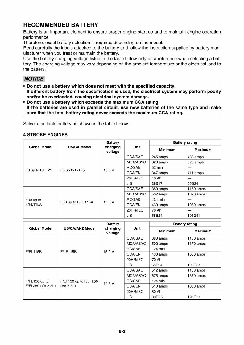
8-2
RECOMMENDED BATTERYBattery is an important element to ensure proper engine start-up and to maintain engine operationperformance.Therefore, exact battery selection is required depending on the model.Read carefully the labels attached to the battery and follow the instruction supplied by battery man-ufacturer when you treat or maintain the battery.Use the battery charging voltage listed in the table below only as a reference when selecting a bat-tery. The charging voltage may vary depending on the ambient temperature or the electrical load tothe battery.
NOTICE• Do not use a battery which does not meet with the specified capacity.
If different battery from the specification is used, the electrical system may perform poorlyand/or be overloaded, causing electrical system damage.
• Do not use a battery which exceeds the maximum CCA rating.If the batteries are used in parallel circuit, use new batteries of the same type and makesure that the total battery rating never exceeds the maximum CCA rating.
Select a suitable battery as shown in the table below.
4-STROKE ENGINES
Global Model US/CA ModelBattery
charging voltage
UnitBattery rating
Minimum Maximum
F8 up to F/FT25 F8 up to F/T25 15.0 V
CCA/SAE 245 amps 433 ampsMCA/ABYC 323 amps 520 amps
RC/SAE 52 min —
CCA/EN 347 amps 411 amps20HR/IEC 40 Ah —
JIS 28B17 55B24
F30 up to F/FL115A
F30 up to F/LF115A 15.0 V
CCA/SAE 380 amps 1150 ampsMCA/ABYC 502 amps 1370 amps
RC/SAE 124 min —
CCA/EN 430 amps 1080 amps
20HR/IEC 70 Ah —JIS 55B24 195G51
Global Model US/CA/ANZ ModelBattery
charging voltage
UnitBattery rating
Minimum Maximum
F/FL115B F/LF115B 15.0 V
CCA/SAE 380 amps 1150 amps
MCA/ABYC 502 amps 1370 amps
RC/SAE 124 min —CCA/EN 430 amps 1080 amps
20HR/IEC 70 Ah —
JIS 55B24 195G51
F/FL150 up to F/FL250 (V6-3.3L)
F/LF150 up to F/LF250 (V6-3.3L)
14.5 V
CCA/SAE 512 amps 1150 amps
MCA/ABYC 675 amps 1370 amps
RC/SAE 124 min —CCA/EN 510 amps 1080 amps
20HR/IEC 80 Ah —
JIS 80D26 195G51
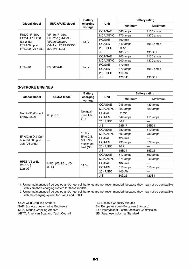
8-3
2-STROKE ENGINES
*1. Using maintenance-free sealed and/or gel cell batteries are not recommended, because they may not be compatiblewith Yamaha’s charging system for these models.
*2. Using maintenance-free sealed and/or gel cell batteries are not recommended, because they may not be compatiblewith the charging system for E/40X and E60H.
CCA: Cold Cranking Ampere RC: Reserve Capacity MinutesSAE: Society of Automotive Engineers EN: European Norm (European Standard)MCA: Marine Cranking Ampere IEC: International Electro-technical CommissionABYC: American Boat and Yacht Council JIS: Japanese Industrial Standard
F150C, F165A, F175A, F/FL200 (L4-2.8L), F/FL200 up to F/FL300 (V6-4.2L)
VF150, F175A, F/LF200 (L4-2.8L), VF200/225/250 (VMAX), F/LF225/250/300 (V6-4.2L)
14.5 V
CCA/SAE 680 amps 1150 ampsMCA/ABYC 770 amps 1370 amps
RC/SAE 160 min —
CCA/EN 640 amps 1080 amps20HR/IEC 80 Ah —
JIS 105D31 195G51
F/FL350 F/LF350CB 14.7 V
CCA/SAE 700 amps 1150 ampsMCA/ABYC 900 amps 1370 amps
RC/SAE 170 min —
CCA/EN 670 amps 1080 amps
20HR/IEC 110 Ah —JIS 120E41 195G51
Global Model US/CA ModelBattery
charging voltage
UnitBattery rating
Minimum Maximum
6 up to 55 (Except E/40X, 55D)
6 up to 50No maxi-mum limit (*1)
CCA/SAE 245 amps 433 amps
MCA/ABYC 323 amps 520 amps
RC/SAE 52 min —CCA/EN 347 amps 411 amps
20HR/IEC 40 Ah —
JIS 28B17 55B24
E/40X, 55D & Car-bureted 60 up to 225 (V6-2.6L)
—
15.0 VE/40X, E/60H: No maximum limit (*2)
CCA/SAE 380 amps 610 amps
MCA/ABYC 502 amps 730 amps
RC/SAE 124 min —CCA/EN 430 amps 579 amps
20HR/IEC 70 Ah —
JIS 55B24 85D26
HPDI (V6-2.6L, V6-3.3L) L/250G
HPDI (V6-2.6L, V6-3.3L)
14.5V
CCA/SAE 512 amps 690 amps
MCA/ABYC 675 amps 840 amps
RC/SAE 182 min —CCA/EN 510 amps 610 amps
20HR/IEC 100 Ah —
JIS 80D26 120E41
Global Model US/CA/ANZ ModelBattery
charging voltage
UnitBattery rating
Minimum Maximum
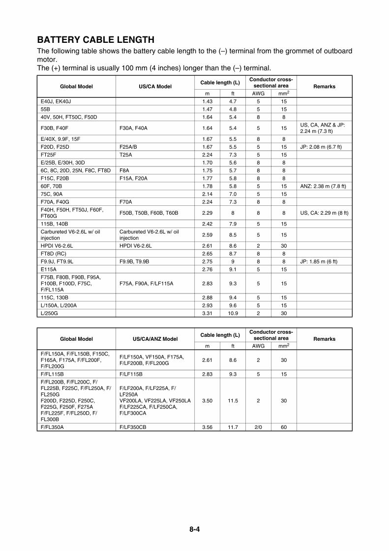
8-4
BATTERY CABLE LENGTHThe following table shows the battery cable length to the (–) terminal from the grommet of outboardmotor.The (+) terminal is usually 100 mm (4 inches) longer than the (–) terminal.
Global Model US/CA ModelCable length (L) Conductor cross-
sectional area Remarksm ft AWG mm2
E40J, EK40J 1.43 4.7 5 15
55B 1.47 4.8 5 15
40V, 50H, FT50C, F50D 1.64 5.4 8 8
F30B, F40F F30A, F40A 1.64 5.4 5 15US, CA, ANZ & JP: 2.24 m (7.3 ft)
E/40X, 9.9F, 15F 1.67 5.5 8 8
F20D, F25D F25A/B 1.67 5.5 5 15 JP: 2.08 m (6.7 ft)
FT25F T25A 2.24 7.3 5 15
E/25B, E/30H, 30D 1.70 5.6 8 8
6C, 8C, 20D, 25N, F8C, FT8D F8A 1.75 5.7 8 8
F15C, F20B F15A, F20A 1.77 5.8 8 8
60F, 70B 1.78 5.8 5 15 ANZ: 2.38 m (7.8 ft)
75C, 90A 2.14 7.0 5 15
F70A, F40G F70A 2.24 7.3 8 8
F40H, F50H, FT50J, F60F, FT60G
F50B, T50B, F60B, T60B 2.29 8 8 8 US, CA: 2.29 m (8 ft)
115B, 140B 2.42 7.9 5 15
Carbureted V6-2.6L w/ oil injection
Carbureted V6-2.6L w/ oil injection
2.59 8.5 5 15
HPDI V6-2.6L HPDI V6-2.6L 2.61 8.6 2 30
FT8D (RC) 2.65 8.7 8 8
F9.9J, FT9.9L F9.9B, T9.9B 2.75 9 8 8 JP: 1.85 m (6 ft)
E115A 2.76 9.1 5 15
F75B, F80B, F90B, F95A, F100B, F100D, F75C, F/FL115A
F75A, F90A, F/LF115A 2.83 9.3 5 15
115C, 130B 2.88 9.4 5 15
L/150A, L/200A 2.93 9.6 5 15
L/250G 3.31 10.9 2 30
Global Model US/CA/ANZ ModelCable length (L) Conductor cross-
sectional area Remarksm ft AWG mm2
F/FL150A, F/FL150B, F150C, F165A, F175A, F/FL200F, F/FL200G
F/LF150A, VF150A, F175A, F/LF200B, F/FL200G
2.61 8.6 2 30
F/FL115B F/LF115B 2.83 9.3 5 15
F/FL200B, F/FL200C, F/FL225B, F225C, F/FL250A, F/FL250GF200D, F225D, F250C, F225G, F250F, F275AF/FL225F, F/FL250D, F/FL300B
F/LF200A, F/LF225A, F/LF250AVF200LA, VF225LA, VF250LAF/LF225CA, F/LF250CA, F/LF300CA
3.50 11.5 2 30
F/FL350A F/LF350CB 3.56 11.7 2/0 60

8-5
100 mm (4 in.) (L)
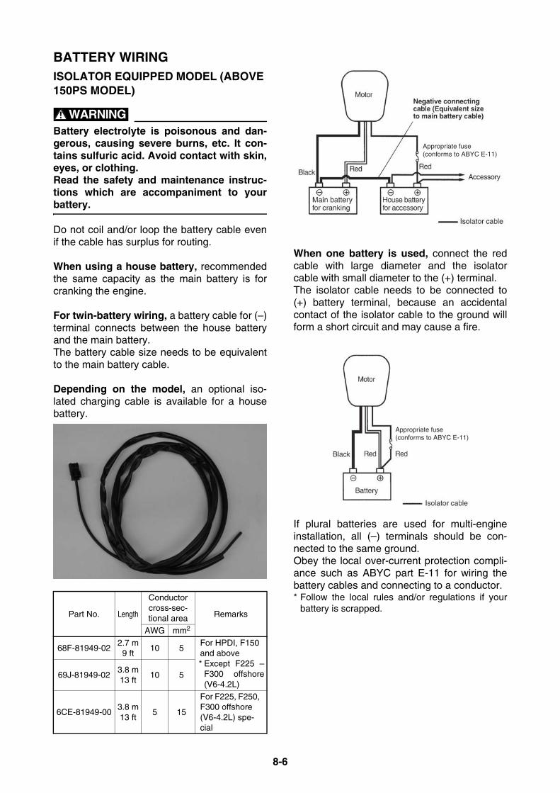
8-6
BATTERY WIRINGISOLATOR EQUIPPED MODEL (ABOVE 150PS MODEL)
WARNINGBattery electrolyte is poisonous and dan-gerous, causing severe burns, etc. It con-tains sulfuric acid. Avoid contact with skin,eyes, or clothing. Read the safety and maintenance instruc-tions which are accompaniment to yourbattery.
Do not coil and/or loop the battery cable evenif the cable has surplus for routing.
When using a house battery, recommendedthe same capacity as the main battery is forcranking the engine.
For twin-battery wiring, a battery cable for (–)terminal connects between the house batteryand the main battery. The battery cable size needs to be equivalentto the main battery cable.
Depending on the model, an optional iso-lated charging cable is available for a housebattery.
When one battery is used, connect the redcable with large diameter and the isolatorcable with small diameter to the (+) terminal. The isolator cable needs to be connected to(+) battery terminal, because an accidentalcontact of the isolator cable to the ground willform a short circuit and may cause a fire.
If plural batteries are used for multi-engineinstallation, all (–) terminals should be con-nected to the same ground. Obey the local over-current protection compli-ance such as ABYC part E-11 for wiring thebattery cables and connecting to a conductor. * Follow the local rules and/or regulations if your
battery is scrapped.Part No. Length
Conductor cross-sec-tional area Remarks
AWG mm2
68F-81949-022.7 m9 ft
10 5For HPDI, F150 and above* Except F225 –
F300 offshore(V6-4.2L)
69J-81949-023.8 m13 ft
10 5
6CE-81949-003.8 m13 ft
5 15
For F225, F250, F300 offshore (V6-4.2L) spe-cial
Appropriate fuse(conforms to ABYC E-11)
Appropriate fuse(conforms to ABYC E-11)
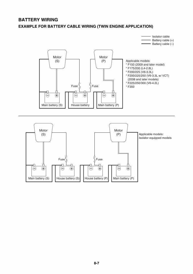
8-7
BATTERY WIRINGEXAMPLE FOR BATTERY CABLE WIRING (TWIN ENGINE APPLICATION)
Fuse
Fuse
Main battery (S) Main battery (P)House battery
Fuse
House battery (S) Main battery (P)House battery (P)
Fuse
Main battery (S)
Motor(P)
Motor(S)
Motor(P)
Motor(S)
Isolator cableBattery cable (+)Battery cable (–)
Applicable models:* F150 (2009 and later model)* F175/200 (L4-2.8L)* F200/225 (V6-3.3L)* F200/225/250 (V6-3.3L w/ VCT) (2008 and later models)* F225/250/300 (V6-4.2L)* F350
Applicable models:Isolator equipped models

8-8
BATTERY WIRINGRECOMMENDED EXTENSION LENGTH OF BATTERY CABLESIf the battery cables are extended, follow the requirements in the table due to the battery capacity,cable size and atmosphere temperature.The length of extension battery cable means the total length of (+) and (–) cables.Be sure to select an extension battery cable and a terminal that meet ABYC requirements or equiv-alents.Use a best-suited stud to the terminal size.Solder the connection of terminals and cables to prevent them from corroding.Coiling and/or looping battery cables should be inhibited because of a power loss.
NOTICEDo not exceed the recommended extension length of battery cable.Otherwise, the electrical system can result in poor performance or damage.
To be continued.
Atmosphere temperature is 0°C (32°F) and above
Applicable modelsBattery Maximum total extension length
Unit RatingAWG420 mm2
AWG230 mm2
AWG1/050 mm2
AWG2/060mm2
Carbureted 150 – 225 (V6-2.6L)4-stroke 115
CCA/SAE 380 amps
3.9 m(13 ft)
6.7 m(22 ft)
10.3 m(34 ft)
—
MCA/ABYC 502 amps
RC/SAE 124 min
CCA/EN 430 amps20HR/IEC 70 Ah
JIS 65D31
4-stroke 150
CCA/SAE 512 amps
6.0 m(20 ft)
10.0 m(33 ft)
16.0 m(52 ft)
—
MCA/ABYC 675 amps
RC/SAE 182 min
CCA/EN 711 amps20HR/IEC 100 Ah
JIS 95E41
HPDI (V6-2.6L)
CCA/SAE 512 amps
8.3 m(27 ft)
14.2 m(47 ft)
22.0 m(72 ft)
—
MCA/ABYC 675 amps
RC/SAE 182 min
CCA/EN 711 amps
20HR/IEC 100 AhJIS 95E41
4-stroke 150, 165, 175, 200 (L4-2.8L)
CCA/SAE 680 amps
2.9 m (10 ft)
4.4 m (14 ft)
7.3 m (24 ft)
8.8 m (29 ft)
MCA/ABYC 770 ampsRC/SAE 160 min
CCA/EN 640 amps
20HR/IEC 80 AhJIS 105D31
CCA/SAE 800 amps
3.2 m (11 ft)
4.8 m (16 ft)
8.0 m (26 ft)
9.6 m (32 ft)
MCA/ABYC 960 ampsRC/SAE 230 min
CCA/EN 750 amps
20HR/IEC 120 AhJIS 130E41
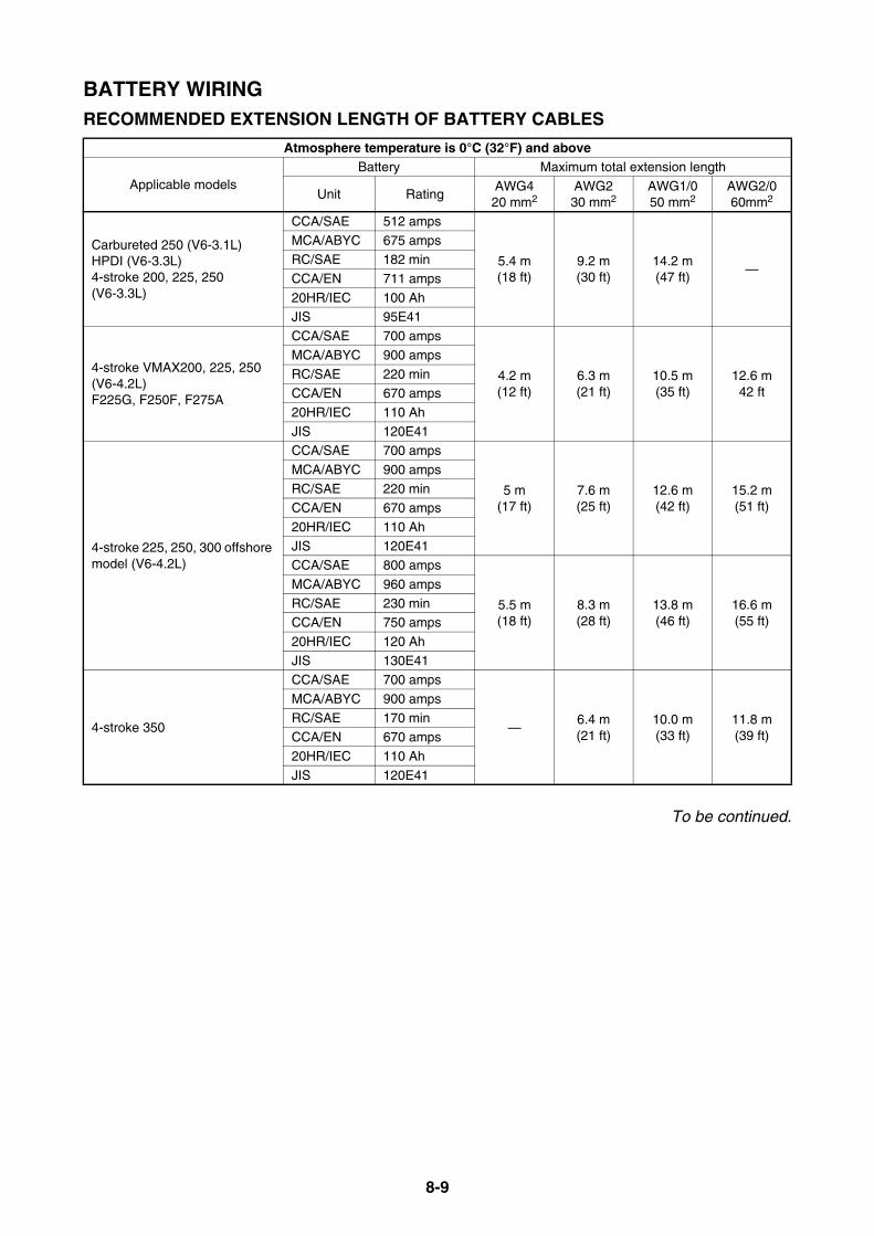
8-9
BATTERY WIRINGRECOMMENDED EXTENSION LENGTH OF BATTERY CABLES
To be continued.
Atmosphere temperature is 0°C (32°F) and above
Applicable modelsBattery Maximum total extension length
Unit RatingAWG420 mm2
AWG230 mm2
AWG1/050 mm2
AWG2/060mm2
Carbureted 250 (V6-3.1L)HPDI (V6-3.3L)4-stroke 200, 225, 250 (V6-3.3L)
CCA/SAE 512 amps
5.4 m(18 ft)
9.2 m(30 ft)
14.2 m(47 ft)
—
MCA/ABYC 675 ampsRC/SAE 182 min
CCA/EN 711 amps
20HR/IEC 100 AhJIS 95E41
4-stroke VMAX200, 225, 250 (V6-4.2L)F225G, F250F, F275A
CCA/SAE 700 amps
4.2 m(12 ft)
6.3 m(21 ft)
10.5 m(35 ft)
12.6 m42 ft
MCA/ABYC 900 amps
RC/SAE 220 minCCA/EN 670 amps
20HR/IEC 110 Ah
JIS 120E41
4-stroke 225, 250, 300 offshore model (V6-4.2L)
CCA/SAE 700 amps
5 m(17 ft)
7.6 m(25 ft)
12.6 m(42 ft)
15.2 m(51 ft)
MCA/ABYC 900 amps
RC/SAE 220 minCCA/EN 670 amps
20HR/IEC 110 Ah
JIS 120E41CCA/SAE 800 amps
5.5 m(18 ft)
8.3 m(28 ft)
13.8 m(46 ft)
16.6 m(55 ft)
MCA/ABYC 960 amps
RC/SAE 230 minCCA/EN 750 amps
20HR/IEC 120 Ah
JIS 130E41
4-stroke 350
CCA/SAE 700 amps
—6.4 m(21 ft)
10.0 m(33 ft)
11.8 m(39 ft)
MCA/ABYC 900 amps
RC/SAE 170 minCCA/EN 670 amps
20HR/IEC 110 Ah
JIS 120E41
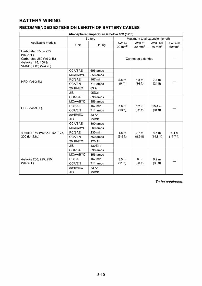
8-10
BATTERY WIRINGRECOMMENDED EXTENSION LENGTH OF BATTERY CABLES
To be continued.
Atmosphere temperature is below 0°C (32°F)
Applicable modelsBattery Maximum total extension length
Unit RatingAWG420 mm2
AWG230 mm2
AWG1/050 mm2
AWG2/060mm2
Carbureted 150 – 225 (V6-2.6L)Carbureted 250 (V6-3.1L)4-stroke 115, 150 & VMAX (SHO) (V-4.2L)
Cannot be extended —
HPDI (V6-2.6L)
CCA/SAE 696 amps
2.8 m(9 ft)
4.8 m(16 ft)
7.4 m(24 ft)
—
MCA/ABYC 856 amps
RC/SAE 167 minCCA/EN 711 amps
20HR/IEC 83 Ah
JIS 95D31
HPDI (V6-3.3L)
CCA/SAE 696 amps
3.9 m(13 ft)
6.7 m(22 ft)
10.4 m(34 ft)
—
MCA/ABYC 856 amps
RC/SAE 167 minCCA/EN 711 amps
20HR/IEC 83 Ah
JIS 95D31
4-stroke 150 (VMAX), 165, 175, 200 (L4-2.8L)
CCA/SAE 800 amps
1.8 m(5.9 ft)
2.7 m(8.9 ft)
4.5 m(14.8 ft)
5.4 n(17.7 ft)
MCA/ABYC 960 amps
RC/SAE 230 minCCA/EN 750 amps
20HR/IEC 120 Ah
JIS 130E41
4-stroke 200, 225, 250 (V6-3.3L)
CCA/SAE 696 amps
3.5 m(11 ft)
6 m(20 ft)
9.2 m(30 ft)
—
MCA/ABYC 856 amps
RC/SAE 167 minCCA/EN 711 amps
20HR/IEC 83 Ah
JIS 95D31
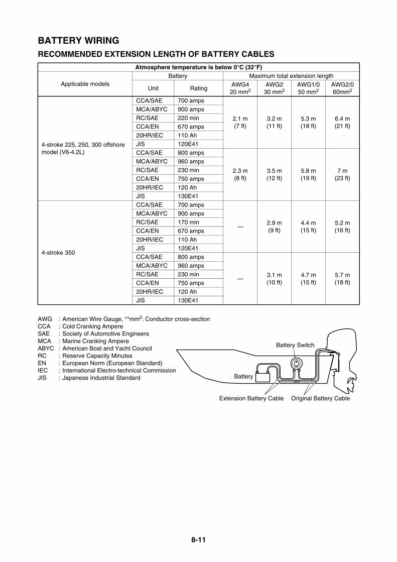
8-11
BATTERY WIRINGRECOMMENDED EXTENSION LENGTH OF BATTERY CABLES
AWG : American Wire Gauge, **mm2: Conductor cross-sectionCCA : Cold Cranking AmpereSAE : Society of Automotive EngineersMCA : Marine Cranking AmpereABYC : American Boat and Yacht CouncilRC : Reserve Capacity MinutesEN : European Norm (European Standard)IEC : International Electro-technical CommissionJIS : Japanese Industrial Standard
Atmosphere temperature is below 0°C (32°F)
Applicable modelsBattery Maximum total extension length
Unit RatingAWG420 mm2
AWG230 mm2
AWG1/050 mm2
AWG2/060mm2
4-stroke 225, 250, 300 offshore model (V6-4.2L)
CCA/SAE 700 amps
2.1 m(7 ft)
3.2 m(11 ft)
5.3 m(18 ft)
6.4 m(21 ft)
MCA/ABYC 900 ampsRC/SAE 220 min
CCA/EN 670 amps
20HR/IEC 110 AhJIS 120E41
CCA/SAE 800 amps
2.3 m(8 ft)
3.5 m(12 ft)
5.8 m(19 ft)
7 m(23 ft)
MCA/ABYC 960 amps
RC/SAE 230 minCCA/EN 750 amps
20HR/IEC 120 Ah
JIS 130E41
4-stroke 350
CCA/SAE 700 amps
—2.9 m (9 ft)
4.4 m (15 ft)
5.2 m (16 ft)
MCA/ABYC 900 amps
RC/SAE 170 minCCA/EN 670 amps
20HR/IEC 110 Ah
JIS 120E41CCA/SAE 800 amps
—3.1 m (10 ft)
4.7 m (15 ft)
5.7 m (18 ft)
MCA/ABYC 960 amps
RC/SAE 230 minCCA/EN 750 amps
20HR/IEC 120 Ah
JIS 130E41
Battery Switch
Extension Battery Cable Original Battery Cable
Battery
ON
OFF
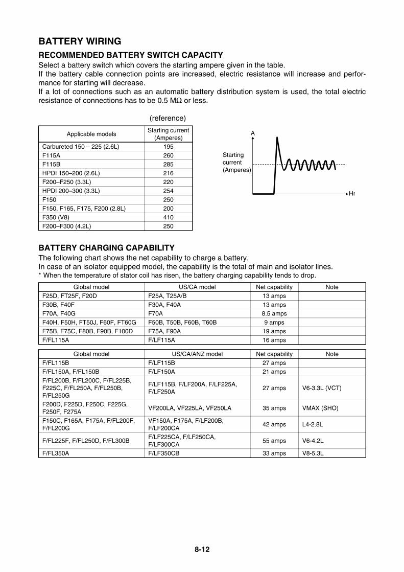
8-12
BATTERY WIRINGRECOMMENDED BATTERY SWITCH CAPACITYSelect a battery switch which covers the starting ampere given in the table.If the battery cable connection points are increased, electric resistance will increase and perfor-mance for starting will decrease.If a lot of connections such as an automatic battery distribution system is used, the total electricresistance of connections has to be 0.5 MΩ or less.
(reference)
BATTERY CHARGING CAPABILITYThe following chart shows the net capability to charge a battery.In case of an isolator equipped model, the capability is the total of main and isolator lines.* When the temperature of stator coil has risen, the battery charging capability tends to drop.
Applicable modelsStarting current
(Amperes)Carbureted 150 – 225 (2.6L) 195
F115A 260
F115B 285
HPDI 150–200 (2.6L) 216F200–F250 (3.3L) 220
HPDI 200–300 (3.3L) 254
F150 250F150, F165, F175, F200 (2.8L) 200
F350 (V8) 410
F200–F300 (4.2L) 250
Global model US/CA model Net capability Note
F25D, FT25F, F20D F25A, T25A/B 13 amps
F30B, F40F F30A, F40A 13 ampsF70A, F40G F70A 8.5 amps
F40H, F50H, FT50J, F60F, FT60G F50B, T50B, F60B, T60B 9 amps
F75B, F75C, F80B, F90B, F100D F75A, F90A 19 ampsF/FL115A F/LF115A 16 amps
Global model US/CA/ANZ model Net capability Note
F/FL115B F/LF115B 27 ampsF/FL150A, F/FL150B F/LF150A 21 amps
F/FL200B, F/FL200C, F/FL225B, F225C, F/FL250A, F/FL250B, F/FL250G
F/LF115B, F/LF200A, F/LF225A,F/LF250A
27 amps V6-3.3L (VCT)
F200D, F225D, F250C, F225G, F250F, F275A
VF200LA, VF225LA, VF250LA 35 amps VMAX (SHO)
F150C, F165A, F175A, F/FL200F, F/FL200G
VF150A, F175A, F/LF200B, F/LF200CA
42 amps L4-2.8L
F/FL225F, F/FL250D, F/FL300BF/LF225CA, F/LF250CA, F/LF300CA
55 amps V6-4.2L
F/FL350A F/LF350CB 33 amps V8-5.3L
Hr
A
Startingcurrent(Amperes)

MEMO

9-1
APPENDIX
MODEL NAME DESIGNATION................................................................ 9-3GLOBAL MODELS IDENTIFICATION CODE ...................................... 9-3
US & CANADA MODELS IDENTIFICATION (CODE).......................... 9-4
US & CANADA NEW MODELS IDENTIFICATION CODE................... 9-4
FUEL SYSTEM VACUUM PRESSURE STANDARD .............................. 9-5FUEL HOSE ROUTING RESISTANCE MEASURING METHOD ........ 9-5
LOWEST VACUUM PRESSURE STANDARD .................................... 9-6
PORTABLE FUEL TANKS (TYPICAL) .................................................... 9-7FUEL PIPES (TYPICAL)........................................................................... 9-8PRIMARY PUMP (TYPICAL).................................................................... 9-8PRE-DELIVERY INSPECTION (PDI) ....................................................... 9-9CONVENTIONAL RIGGING KIT CONTENTS ....................................... 9-10
DIGITAL TACHOMETER KIT ............................................................. 9-10
DIGITAL TACHOMETER AND SPEEDOMETER KIT........................ 9-10
TWIN-MOTOR KIT ............................................................................. 9-11
REMOTE OIL TANK KIT (FOR 2-STROKE ENGINE)........................ 9-12
DIGITAL NETWORK GAUGE RIGGING KIT CONTENTS .................... 9-13SQUARE/ROUND STYLE GAUGE RIGGING KIT CONTENTS
FOR US AND CANADA................................................................. 9-13
SQUARE STYLE GAUGE RIGGING KIT FOR EUROPE .................. 9-13
ROUND STYLE GAUGE RIGGING KIT FOR EUROPE .................... 9-17
SQUARE STYLE GAUGE RIGGING KIT FOR ANZ .......................... 9-18
SQUARE STYLE GAUGE RIGGING KIT FOR ANZ .......................... 9-19
SQUARE STYLE GAUGE RIGGING KIT FOR JAPAN...................... 9-20
ROUND STYLE GAUGE RIGGING KIT FOR JAPAN........................ 9-21
IMMOBILIZER RIGGING KIT CONTENTS ............................................ 9-22IMMOBILIZER KIT 1 (FOR US, ANZ, CRB) ....................................... 9-22
IMMOBILIZER KIT 2 (FOR JPN) ........................................................ 9-22
SINGLE ENGINE GAUGE KIT FOR IMMOBILIZER
(FOR EU, ANZ, JPN, GEN) ........................................................... 9-22
TWIN ENGINE GAUGE KIT FOR IMMOBILIZER .............................. 9-23
To be continued.

9-2
APPENDIX
DIGITAL NETWORK PREMIUM GAUGE RIGGING KIT CONTENTS........................................................................................ 9-24SINGLE ENGINE PREMIUM GAUGE KIT ......................................... 9-24
ADDITIONAL PREMIUM GAUGE KIT (EU, ANZ, GEN) .................... 9-24
TWIN ENGINE PREMIUM GAUGE KIT ............................................. 9-25
TRIPLE ENGINE PREMIUM GAUGE KIT (FOR EU, ANZ, GEN)...... 9-25
MAIN HELM SW PANEL TWIN ENGINE KIT (FOR US, CAN) .......... 9-25
MAIN HELM SW PANEL TRIPLE ENGINE KIT (FOR US, CAN)....... 9-26
2ND HELM SW PANEL SINGLE ENGINE KIT (FOR US, CAN)........ 9-26
2ND HELM SW PANEL TWIN ENGINE KIT (FOR US, CAN)............ 9-26
2ND HELM SW PANEL TRIPLE ENGINE KIT (FOR US, CAN) ........ 9-26
OTHER RIGGING KIT CONTENTS........................................................ 9-27TILT LIMIT SWITCH KIT (FOR US, CA, EU, ANZ, RUS, JPN).......... 9-27
TILT LIMIT SWITCH KIT 2
(FOR US, CA, EU, ANZ, JP, RUS, TUR)....................................... 9-27
TILT LIMIT SWITCH KIT 3
(FOR US, CA, EU, ANZ, JP, RUS, TUR)....................................... 9-28
TILT LIMIT SWITCH KIT 4
(FOR US, CA, EU, ANZ, JP, RUS, TUR)....................................... 9-28
LIGHTING COIL KIT (FOR EU, CA, JPN) .......................................... 9-29
2014 YEAR MODELS MANUFACTURE STARTING SERIAL NUMBERS.......................................................................................... 9-30
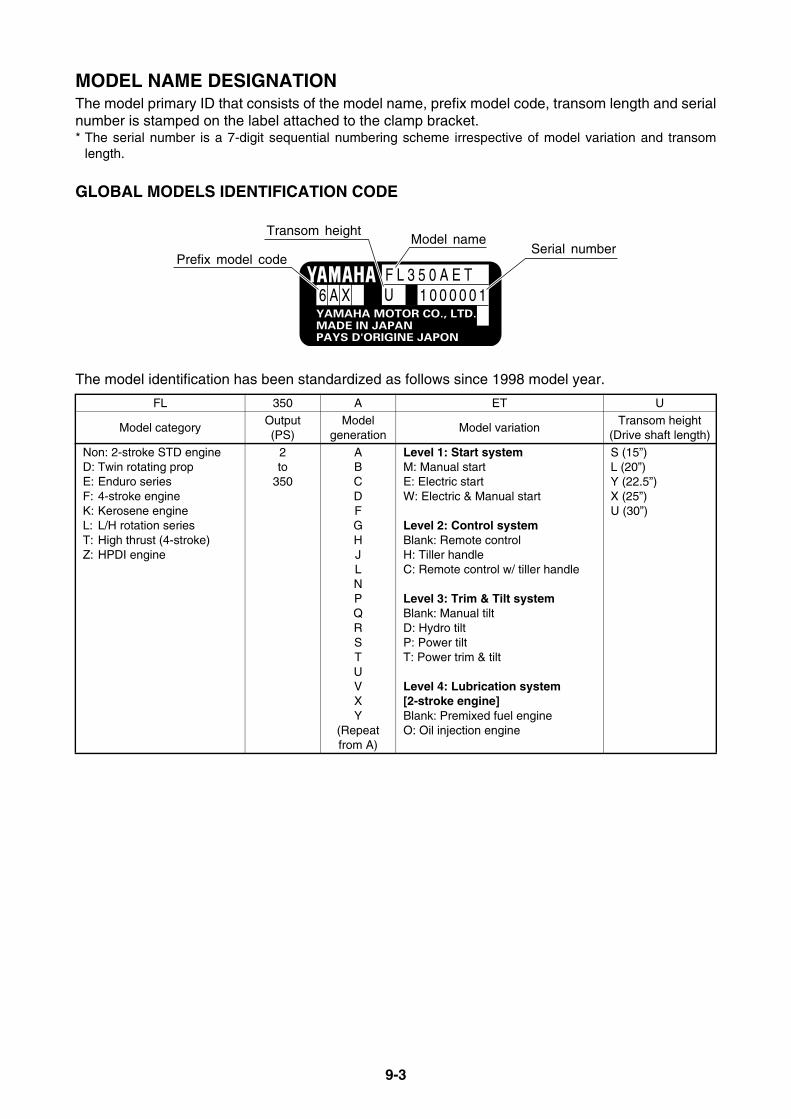
9-3
MODEL NAME DESIGNATIONThe model primary ID that consists of the model name, prefix model code, transom length and serialnumber is stamped on the label attached to the clamp bracket.* The serial number is a 7-digit sequential numbering scheme irrespective of model variation and transom
length.
GLOBAL MODELS IDENTIFICATION CODE
The model identification has been standardized as follows since 1998 model year.
FL 350 A ET U
Model categoryOutput(PS)
Modelgeneration
Model variationTransom height
(Drive shaft length)
Non: 2-stroke STD engineD: Twin rotating propE: Enduro seriesF: 4-stroke engineK: Kerosene engineL: L/H rotation seriesT: High thrust (4-stroke)Z: HPDI engine
2to
350
ABCDFGHJLNPQRSTUVXY
(Repeat from A)
Level 1: Start systemM: Manual startE: Electric startW: Electric & Manual start
Level 2: Control systemBlank: Remote controlH: Tiller handleC: Remote control w/ tiller handle
Level 3: Trim & Tilt systemBlank: Manual tiltD: Hydro tiltP: Power tiltT: Power trim & tilt
Level 4: Lubrication system[2-stroke engine]Blank: Premixed fuel engineO: Oil injection engine
S (15”)L (20”)Y (22.5”)X (25”)U (30”)
YAMAHA MOTOR CO., LTD.MADE IN JAPANPAYS D'ORIGINE JAPON
6 A XF L 3 5 0 A E TU
Prefix model code
Transom heightModel name
Serial number

9-4
MODEL NAME DESIGNATIONUS & CANADA MODELS IDENTIFICATION (CODE)
US & CANADA NEW MODELS IDENTIFICATION CODEThe model codes for the current US and Canada models are described in a simplified form asshown below.For Australia and New Zealand, the same model codes as US and Canada models are used for 4-stroke 150HP and larger models.For the model codes for previous models, see 2013 Rigging Guide or earlier editions.
F 40 L E H A
Modelcategory
Power output
Driveshaft length
Starting method PT/T Control method Model generation
F: 4-stroke modelL: L/H rotation modelV: VMAX seriesT: High thrust model
2.5–350 S: 15”L: 20”X: 25”U: 30”J: Jet driveN: With-out lower-case
Blank: PTT & E-startP: PT & E-startE: Electric startM: Manual start
Blank: Remote controlH: Tiller handleC: Command Link
Control (DEC)
A: New model (1st change on motor)B: 2nd change on motorC: 3rd change on motoretc.
YAMAHA MOTOR CO., LTD.MADE IN JAPANPAYS D'ORIGINE JAPON
6 B GF 4 0 L E H AL
Serial numberPrefix model code
Model nameTransom height
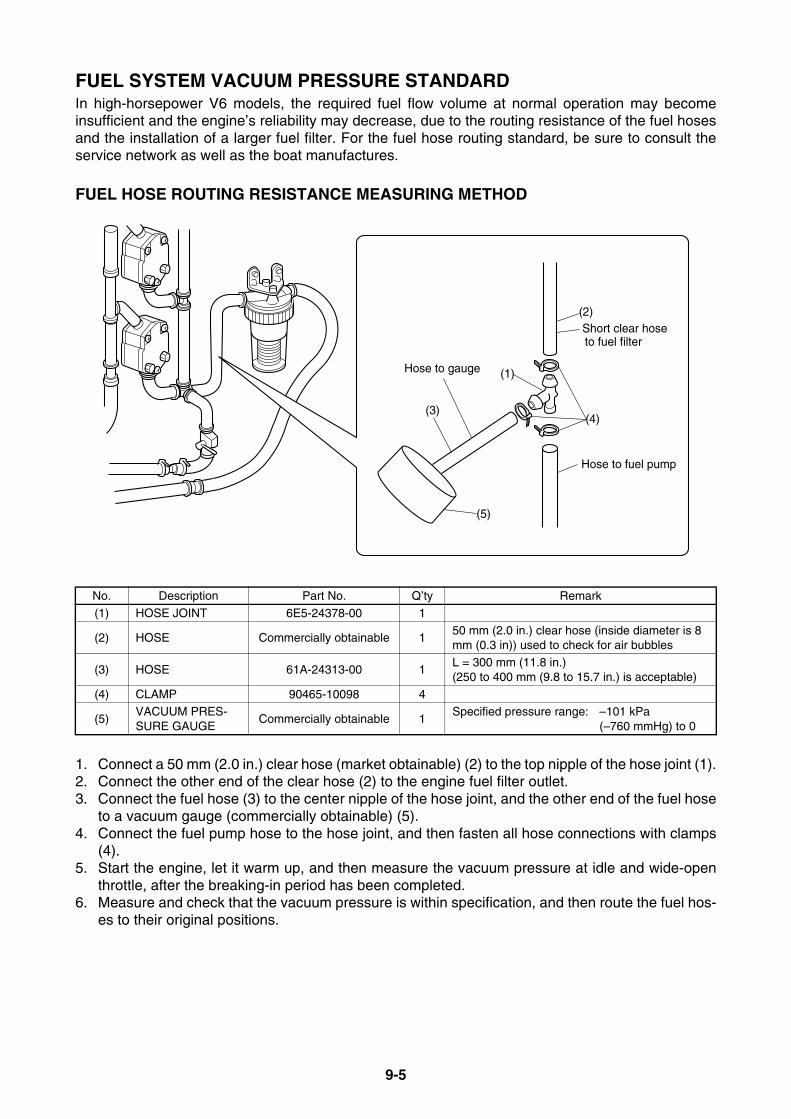
9-5
FUEL SYSTEM VACUUM PRESSURE STANDARDIn high-horsepower V6 models, the required fuel flow volume at normal operation may becomeinsufficient and the engine’s reliability may decrease, due to the routing resistance of the fuel hosesand the installation of a larger fuel filter. For the fuel hose routing standard, be sure to consult theservice network as well as the boat manufactures.
FUEL HOSE ROUTING RESISTANCE MEASURING METHOD
1. Connect a 50 mm (2.0 in.) clear hose (market obtainable) (2) to the top nipple of the hose joint (1).2. Connect the other end of the clear hose (2) to the engine fuel filter outlet.3. Connect the fuel hose (3) to the center nipple of the hose joint, and the other end of the fuel hose
to a vacuum gauge (commercially obtainable) (5).4. Connect the fuel pump hose to the hose joint, and then fasten all hose connections with clamps
(4).5. Start the engine, let it warm up, and then measure the vacuum pressure at idle and wide-open
throttle, after the breaking-in period has been completed.6. Measure and check that the vacuum pressure is within specification, and then route the fuel hos-
es to their original positions.
No. Description Part No. Q’ty Remark
(1) HOSE JOINT 6E5-24378-00 1
(2) HOSE Commercially obtainable 150 mm (2.0 in.) clear hose (inside diameter is 8 mm (0.3 in)) used to check for air bubbles
(3) HOSE 61A-24313-00 1L = 300 mm (11.8 in.) (250 to 400 mm (9.8 to 15.7 in.) is acceptable)
(4) CLAMP 90465-10098 4
(5)VACUUM PRES-SURE GAUGE
Commercially obtainable 1Specified pressure range: –101 kPa
(–760 mmHg) to 0
(3)
Hose to fuel pump
(2)
(1)
(4)
(5)
Hose to gauge
Short clear hose to fuel filter

9-6
FUEL SYSTEM VACUUM PRESSURE STANDARDLOWEST VACUUM PRESSURE STANDARDThe lowest vacuum pressure must be fulfilled as below at an atmospheric temperature of 20°C(68°F) and higher.
* Be sure to measure and check that the vacuum pressure is within specification at idle and wide-openthrottle, after the breaking-in period has been completed.
Engine breaking-in operating conditions : 10 hours• 2-stroke carbureted models : Use 25:1 pre-mixed fuel.• 2-stroke electronic fuel injected models : Use 50:1 pre-mixed fuel, and supply with oil injection.• HPDI models : Use straight gasoline (only supply with oil injection)• 4-stroke models : Use straight gasoline.
Larger fuel filters installed onto a boat may lower the fuel vacuum pressure to –20.0 kPa (–15 mmHg) andunder. Therefore, follow the instructions mentioned above to rig the boat properly so that the fuel vacuumpressure is within specification.If the vacuum pressure does not surpass –10.7 kPa (–80 mmHg) at wide-open throttle, use a clear hose tocheck that air bubbles are not mixed in the fuel.
Idle: 0 kPa to –10.7 kPa (–80 mmHg)WOT: –10.7 kPa (–80 mmHg) to –20 kPa (–150 mmHg)
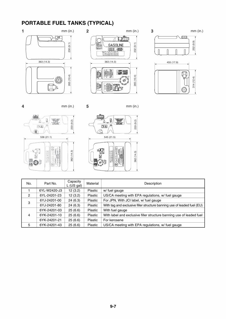
9-7
PORTABLE FUEL TANKS (TYPICAL)
No. Part No.Capacity
L (US gal)Material Description
1 6YL-W2420-J3 12 (3.2) Plastic w/ fuel gauge2 6YL-24201-23 12 (3.2) Plastic US/CA meeting with EPA regulations, w/ fuel gauge
36YJ-24201-00 24 (6.3) Plastic For JPN, With JCI label, w/ fuel gauge
6YJ-24201-80 24 (6.3) Plastic With tag and exclusive filler structure banning use of leaded fuel (EU)
4
6YK-24201-03 25 (6.6) Plastic With fuel gauge
6YK-24201-10 25 (6.6) Plastic With label and exclusive filler structure banning use of leaded fuel
6YK-24201-21 25 (6.6) Plastic For kerosene5 6YK-24201-43 25 (6.6) Plastic US/CA meeting with EPA regulations, w/ fuel gauge
1 2 3 mm (in.)mm (in.)mm (in.)
363 (14.3)
265
(10.
4)23
0 (9
.1)
363 (14.3)
265
(10.
4)23
2 (9
.1)
455 (17.9)
252
(9.9
)31
4 (1
2.4)
4 5 mm (in.)mm (in.)
536 (21.1)
233
(9.2
)36
2 (1
4.3)
545 (21.5)23
3 (9
.2)
362
(14.
3)

9-8
FUEL PIPES (TYPICAL)
PRIMARY PUMP (TYPICAL)
No. Part No. Hose inside diameter Length (L) Remarks1 6Y1-24306-55 6 mm (0.24 in) 3 m (10 ft) For small engines
2 6YK-24306-64 8 mm (0.31 in) 3 m (10 ft) US/CA meeting with EPA regulations
3 6YK-24306-04 6 mm (0.24 in) 3 m (10 ft) For kerosene models
Part No. Hose inside diameter Remarks6YK-24360-73 8 mm (0.31 in) Meeting with EPA regulations, Above F75
6YL-24360-51 6 mm (0.24 in)
(L)(L)
(L)
1 2
3
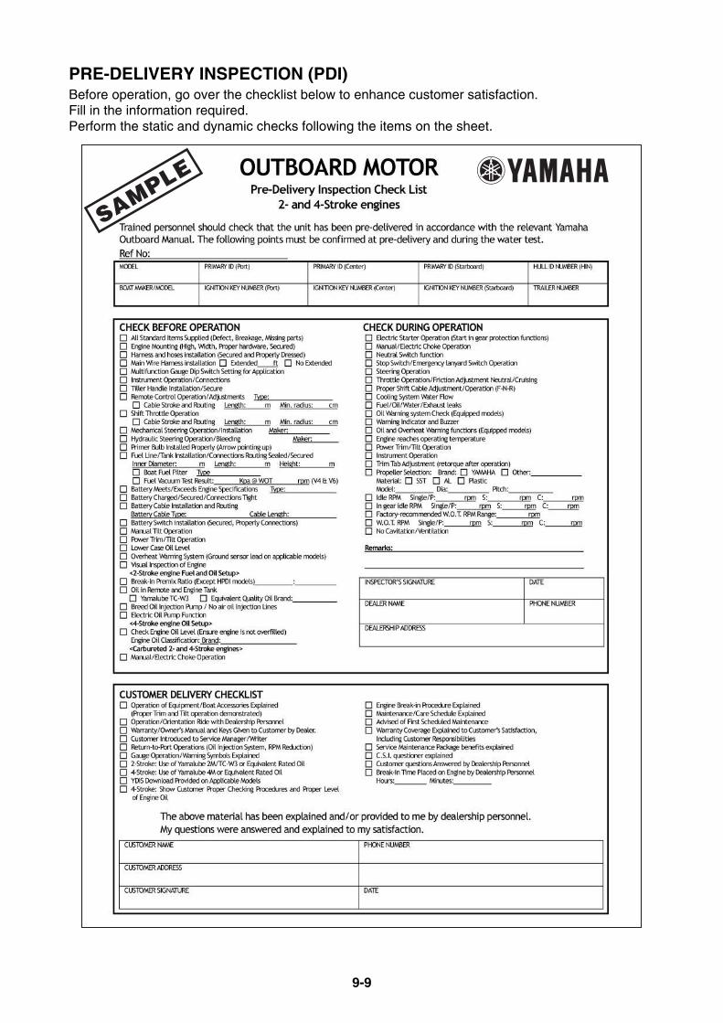
9-9
PRE-DELIVERY INSPECTION (PDI)Before operation, go over the checklist below to enhance customer satisfaction.Fill in the information required.Perform the static and dynamic checks following the items on the sheet.
SAMPLE

9-10
CONVENTIONAL RIGGING KIT CONTENTSThe rigging kit is handled by Marine Sales Division of Yamaha Motor Corporation.Thereby, Yamaha parts distribution center in Japan is not in charge of distribution of the kit.Attention to importers, the rigging kit must be purchased from Sales Division as well as outboard-motors because it is impossible to purchase from the parts route.
DIGITAL TACHOMETER KITUS/CA: Above 40, Above F30Others: Above 40 (3-cyl) w/ oil injection (except 250G & L250G), Above F30
P/N: 6YR-W0035-E3
DIGITAL TACHOMETER AND SPEEDOMETER KITUS/CA: Above 40, Above F30Others: Above 40 (3-cyl) w/ oil injection (except 250G & L250G), Above F30
P/N: 6YR-W0035-F3
ANZ: Fuel injected F50-F100
P/N: 6YR-W0035-T1
Part name Part No. Q’ty Remarks
EXT wire-lead 6Y5-83653-20 1 7 m (23 ft)
Tachometer ASSY 6Y5-8350T-91 1 Included instruction tagWire-lead 6Y5-83553-20 1 2.5 m (8 ft) w/10 amp fuse
Part name Part No. Q’ty RemarksWire-lead 6Y5-83553-N0 1 2.5 m (8 ft) w/10 amp twin-fuse
Tachometer ASSY 6Y5-8350T-91 1 Included instruction tag
EXT wire-lead 6Y5-83653-30 1 8 m (26 ft)Speedometer ASSY 6Y5-83570-S6 1 Included instruction tag
Tube 6Y5-83557-10 1 8 m (26 ft)
Clamp 90465-11M10 2Clamp 90465-13M18 10
Instruction 61A-28107-A4 1
Part name Part No. Q’ty RemarksWire-lead 6Y5-82117-00 1 30 cm (1 ft), BLK
Tachometer ASSY 6Y5-8350T-91 1 Included instruction tag
Wire-lead 6Y5-83553-M0 1 2.5 m (8 ft) w/10 amp twin-fuseTube 6Y5-83557-10 1 8 m (26 ft)
Speedometer ASSY 6Y5-83570-S6 1 Included instruction tag
EXT wire-lead 6Y5-83653-30 1 8 m (26 ft)Clamp 90465-11M10 2
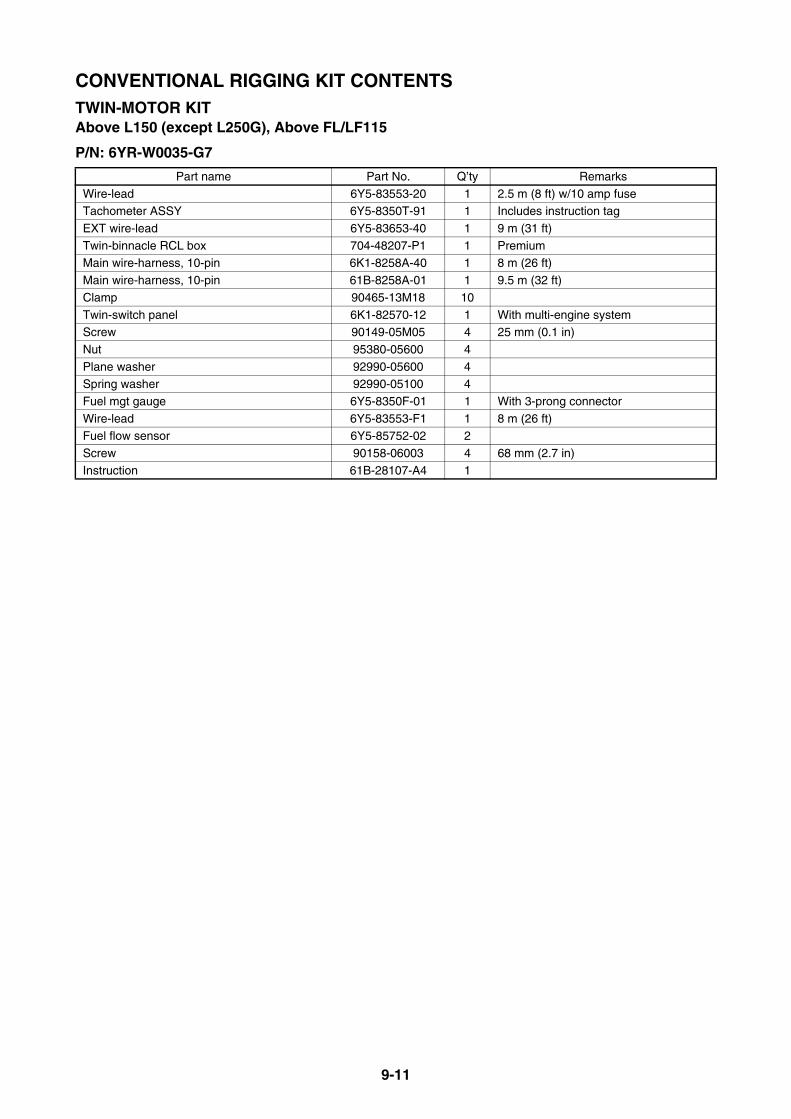
9-11
CONVENTIONAL RIGGING KIT CONTENTSTWIN-MOTOR KITAbove L150 (except L250G), Above FL/LF115
P/N: 6YR-W0035-G7
Part name Part No. Q’ty Remarks
Wire-lead 6Y5-83553-20 1 2.5 m (8 ft) w/10 amp fuseTachometer ASSY 6Y5-8350T-91 1 Includes instruction tag
EXT wire-lead 6Y5-83653-40 1 9 m (31 ft)
Twin-binnacle RCL box 704-48207-P1 1 PremiumMain wire-harness, 10-pin 6K1-8258A-40 1 8 m (26 ft)
Main wire-harness, 10-pin 61B-8258A-01 1 9.5 m (32 ft)
Clamp 90465-13M18 10
Twin-switch panel 6K1-82570-12 1 With multi-engine systemScrew 90149-05M05 4 25 mm (0.1 in)
Nut 95380-05600 4
Plane washer 92990-05600 4Spring washer 92990-05100 4
Fuel mgt gauge 6Y5-8350F-01 1 With 3-prong connector
Wire-lead 6Y5-83553-F1 1 8 m (26 ft)Fuel flow sensor 6Y5-85752-02 2
Screw 90158-06003 4 68 mm (2.7 in)
Instruction 61B-28107-A4 1
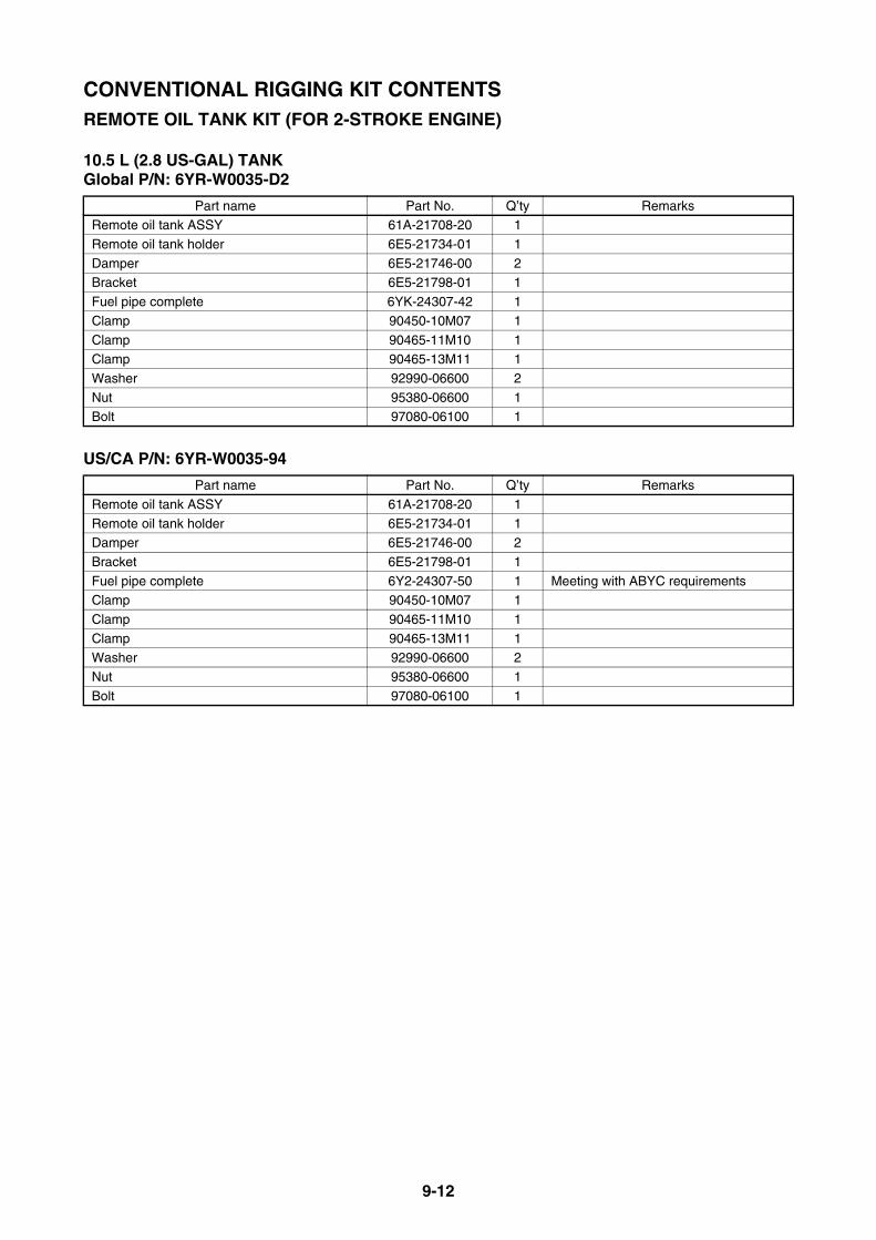
9-12
CONVENTIONAL RIGGING KIT CONTENTSREMOTE OIL TANK KIT (FOR 2-STROKE ENGINE)
10.5 L (2.8 US-GAL) TANKGlobal P/N: 6YR-W0035-D2
US/CA P/N: 6YR-W0035-94
Part name Part No. Q’ty RemarksRemote oil tank ASSY 61A-21708-20 1
Remote oil tank holder 6E5-21734-01 1
Damper 6E5-21746-00 2Bracket 6E5-21798-01 1
Fuel pipe complete 6YK-24307-42 1
Clamp 90450-10M07 1
Clamp 90465-11M10 1Clamp 90465-13M11 1
Washer 92990-06600 2
Nut 95380-06600 1Bolt 97080-06100 1
Part name Part No. Q’ty Remarks
Remote oil tank ASSY 61A-21708-20 1
Remote oil tank holder 6E5-21734-01 1Damper 6E5-21746-00 2
Bracket 6E5-21798-01 1
Fuel pipe complete 6Y2-24307-50 1 Meeting with ABYC requirementsClamp 90450-10M07 1
Clamp 90465-11M10 1
Clamp 90465-13M11 1Washer 92990-06600 2
Nut 95380-06600 1
Bolt 97080-06100 1

9-13
DIGITAL NETWORK GAUGE RIGGING KIT CONTENTSSQUARE/ROUND STYLE GAUGE RIGGING KIT CONTENTS FOR US AND CANADAThe above kit is available from Yamaha Motor Corporation, USA.
SQUARE STYLE GAUGE RIGGING KIT FOR EUROPESINGLE KIT (TACH, SPEED/FUEL MGT)Kit P/N: 6YR-W0035-N8
SINGLE KIT (TACH, SPEED/FUEL MGT) w/o Speed Sensor Kit Kit P/N: 6YR-W0035-F0
Part No. Part name Q’ty Remarks60V-8A4L1-13 Speed sensor kit 1 Refer to kit contents
6Y8-81920-01 Multi-hub 1 With resistor cap, GRY
6Y8-81920-11 Single-hub 1 With resistor6Y8-82521-11 Pigtail bus wire, 0.6 m (2 ft) 2
6Y8-82521-31 Pigtail bus wire, 1.8 m (6 ft) 1
6Y8-82553-21 Main bus wire, 6.1 m (20 ft) 1
6Y8-82582-11 4-pin cap, WHT 1 For waterproof6Y8-83500-01 SQR comb. speedometer & fuel mgt gauge 1
6Y8-8350T-01 SQR tachometer 1
6Y8-83553-01 PWR supply wire, 2.4 m (8 ft) 1 With 10 amp fuse6Y8-8356N-01 Fuel tank & GPS wire 1
6Y8-2819U-X2 Quick operation guide 1
6Y8-2819K-S1 Quick installation guide 16Y8-2819U-20 Operation manual 1
Part No. Part name Q’ty Remarks
6Y8-81920-01 Multi-hub 1 With resistor cap, GRY6Y8-81920-11 Single-hub 1 With resistor
6Y8-82521-11 Pigtail bus wire, 0.6 m (2 ft) 2
6Y8-82521-31 Pigtail bus wire, 0.6 m (2 ft) 16Y8-82553-21 Main bus wire, 6.1 m (20 ft) 1
6Y8-82582-11 4-pin cap, WHT 1 For waterproof
6Y8-83500-01 SQR comb. speedometer & fuel mgt gauge 16Y8-8350T-01 SQR tachometer 1
6Y8-83553-01 PWR supply wire, 2.4 m (8 ft) 1 With 10 amp fuse
6Y8-8356N-01 Fuel tank & GPS wire 16Y8-2819U-X2 Quick operation guide 1
6Y8-2819K-S1 Quick installation guide 1
6Y8-2819U-70 Operation manual 1 16Y8-2819U-80 Operation manual 2 1
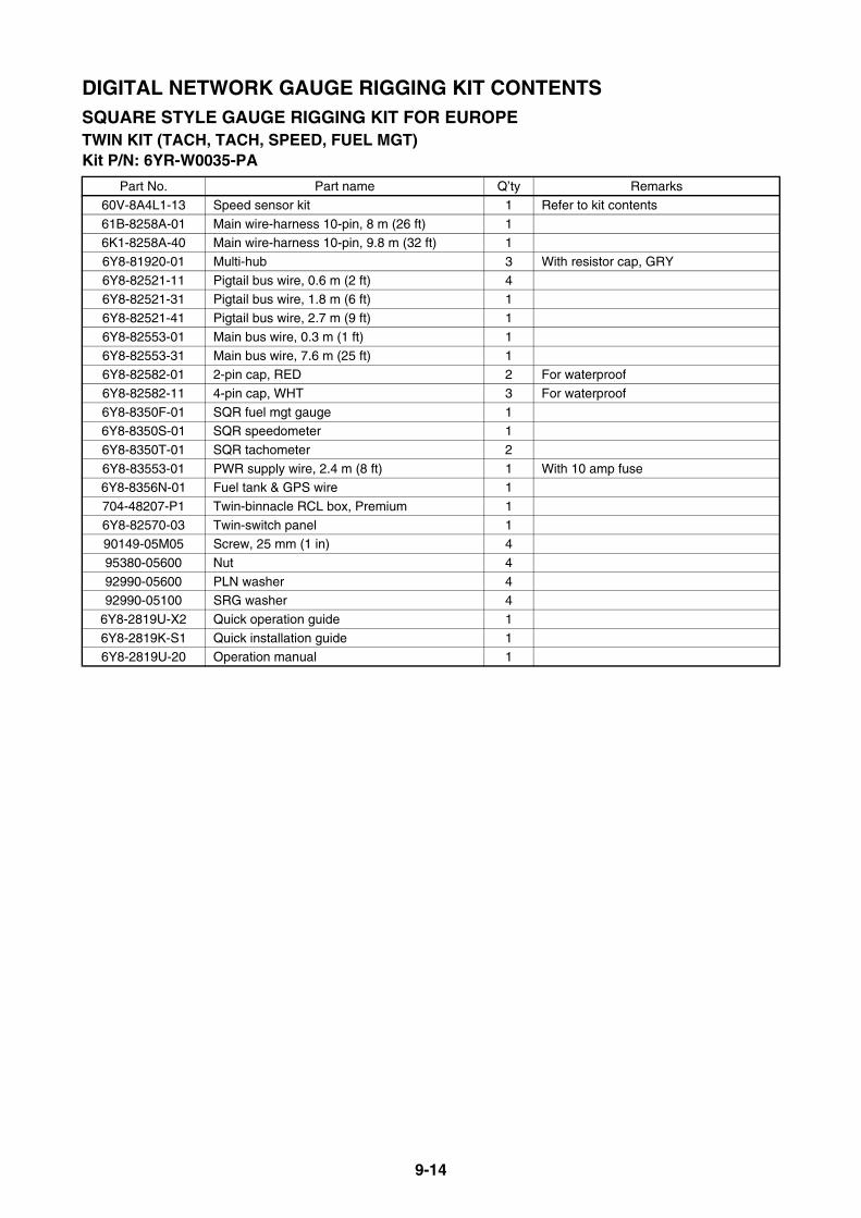
9-14
DIGITAL NETWORK GAUGE RIGGING KIT CONTENTSSQUARE STYLE GAUGE RIGGING KIT FOR EUROPETWIN KIT (TACH, TACH, SPEED, FUEL MGT)Kit P/N: 6YR-W0035-PA
Part No. Part name Q’ty Remarks
60V-8A4L1-13 Speed sensor kit 1 Refer to kit contents
61B-8258A-01 Main wire-harness 10-pin, 8 m (26 ft) 16K1-8258A-40 Main wire-harness 10-pin, 9.8 m (32 ft) 1
6Y8-81920-01 Multi-hub 3 With resistor cap, GRY
6Y8-82521-11 Pigtail bus wire, 0.6 m (2 ft) 46Y8-82521-31 Pigtail bus wire, 1.8 m (6 ft) 1
6Y8-82521-41 Pigtail bus wire, 2.7 m (9 ft) 1
6Y8-82553-01 Main bus wire, 0.3 m (1 ft) 1
6Y8-82553-31 Main bus wire, 7.6 m (25 ft) 16Y8-82582-01 2-pin cap, RED 2 For waterproof
6Y8-82582-11 4-pin cap, WHT 3 For waterproof
6Y8-8350F-01 SQR fuel mgt gauge 16Y8-8350S-01 SQR speedometer 1
6Y8-8350T-01 SQR tachometer 2
6Y8-83553-01 PWR supply wire, 2.4 m (8 ft) 1 With 10 amp fuse6Y8-8356N-01 Fuel tank & GPS wire 1
704-48207-P1 Twin-binnacle RCL box, Premium 1
6Y8-82570-03 Twin-switch panel 190149-05M05 Screw, 25 mm (1 in) 4
95380-05600 Nut 4
92990-05600 PLN washer 492990-05100 SRG washer 4
6Y8-2819U-X2 Quick operation guide 1
6Y8-2819K-S1 Quick installation guide 16Y8-2819U-20 Operation manual 1
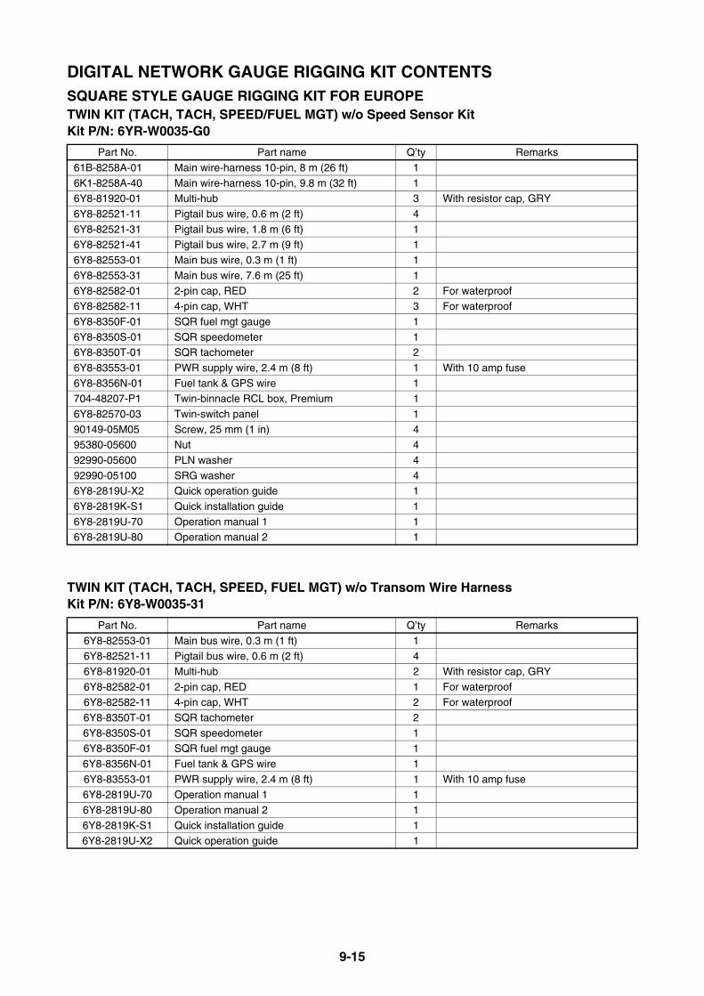
9-15
DIGITAL NETWORK GAUGE RIGGING KIT CONTENTSSQUARE STYLE GAUGE RIGGING KIT FOR EUROPETWIN KIT (TACH, TACH, SPEED/FUEL MGT) w/o Speed Sensor Kit Kit P/N: 6YR-W0035-G0
TWIN KIT (TACH, TACH, SPEED, FUEL MGT) w/o Transom Wire HarnessKit P/N: 6Y8-W0035-31
Part No. Part name Q’ty Remarks
61B-8258A-01 Main wire-harness 10-pin, 8 m (26 ft) 1
6K1-8258A-40 Main wire-harness 10-pin, 9.8 m (32 ft) 16Y8-81920-01 Multi-hub 3 With resistor cap, GRY
6Y8-82521-11 Pigtail bus wire, 0.6 m (2 ft) 4
6Y8-82521-31 Pigtail bus wire, 1.8 m (6 ft) 16Y8-82521-41 Pigtail bus wire, 2.7 m (9 ft) 1
6Y8-82553-01 Main bus wire, 0.3 m (1 ft) 1
6Y8-82553-31 Main bus wire, 7.6 m (25 ft) 1
6Y8-82582-01 2-pin cap, RED 2 For waterproof6Y8-82582-11 4-pin cap, WHT 3 For waterproof
6Y8-8350F-01 SQR fuel mgt gauge 1
6Y8-8350S-01 SQR speedometer 16Y8-8350T-01 SQR tachometer 2
6Y8-83553-01 PWR supply wire, 2.4 m (8 ft) 1 With 10 amp fuse
6Y8-8356N-01 Fuel tank & GPS wire 1704-48207-P1 Twin-binnacle RCL box, Premium 1
6Y8-82570-03 Twin-switch panel 1
90149-05M05 Screw, 25 mm (1 in) 495380-05600 Nut 4
92990-05600 PLN washer 4
92990-05100 SRG washer 46Y8-2819U-X2 Quick operation guide 1
6Y8-2819K-S1 Quick installation guide 1
6Y8-2819U-70 Operation manual 1 16Y8-2819U-80 Operation manual 2 1
Part No. Part name Q’ty Remarks
6Y8-82553-01 Main bus wire, 0.3 m (1 ft) 16Y8-82521-11 Pigtail bus wire, 0.6 m (2 ft) 4
6Y8-81920-01 Multi-hub 2 With resistor cap, GRY
6Y8-82582-01 2-pin cap, RED 1 For waterproof6Y8-82582-11 4-pin cap, WHT 2 For waterproof
6Y8-8350T-01 SQR tachometer 2
6Y8-8350S-01 SQR speedometer 16Y8-8350F-01 SQR fuel mgt gauge 1
6Y8-8356N-01 Fuel tank & GPS wire 1
6Y8-83553-01 PWR supply wire, 2.4 m (8 ft) 1 With 10 amp fuse6Y8-2819U-70 Operation manual 1 1
6Y8-2819U-80 Operation manual 2 1
6Y8-2819K-S1 Quick installation guide 16Y8-2819U-X2 Quick operation guide 1
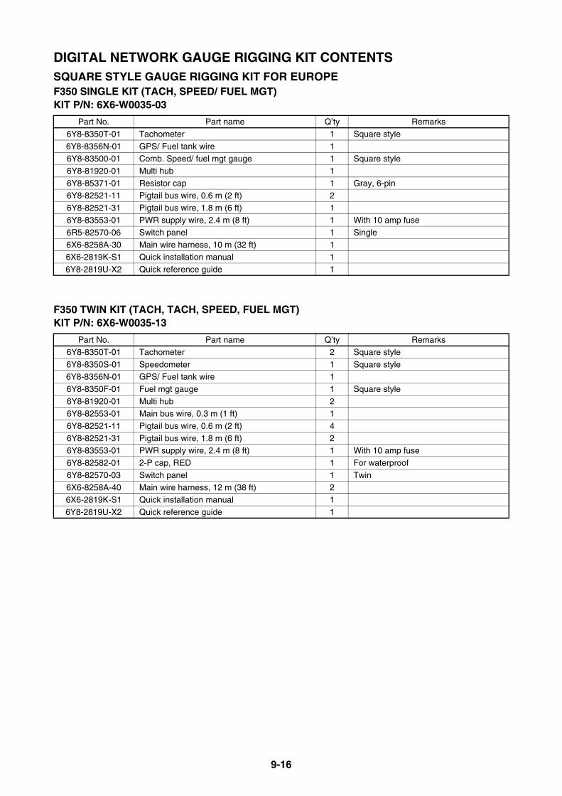
9-16
DIGITAL NETWORK GAUGE RIGGING KIT CONTENTSSQUARE STYLE GAUGE RIGGING KIT FOR EUROPEF350 SINGLE KIT (TACH, SPEED/ FUEL MGT)KIT P/N: 6X6-W0035-03
F350 TWIN KIT (TACH, TACH, SPEED, FUEL MGT)KIT P/N: 6X6-W0035-13
Part No. Part name Q’ty Remarks
6Y8-8350T-01 Tachometer 1 Square style
6Y8-8356N-01 GPS/ Fuel tank wire 16Y8-83500-01 Comb. Speed/ fuel mgt gauge 1 Square style
6Y8-81920-01 Multi hub 1
6Y8-85371-01 Resistor cap 1 Gray, 6-pin6Y8-82521-11 Pigtail bus wire, 0.6 m (2 ft) 2
6Y8-82521-31 Pigtail bus wire, 1.8 m (6 ft) 1
6Y8-83553-01 PWR supply wire, 2.4 m (8 ft) 1 With 10 amp fuse
6R5-82570-06 Switch panel 1 Single6X6-8258A-30 Main wire harness, 10 m (32 ft) 1
6X6-2819K-S1 Quick installation manual 1
6Y8-2819U-X2 Quick reference guide 1
Part No. Part name Q’ty Remarks
6Y8-8350T-01 Tachometer 2 Square style
6Y8-8350S-01 Speedometer 1 Square style6Y8-8356N-01 GPS/ Fuel tank wire 1
6Y8-8350F-01 Fuel mgt gauge 1 Square style
6Y8-81920-01 Multi hub 26Y8-82553-01 Main bus wire, 0.3 m (1 ft) 1
6Y8-82521-11 Pigtail bus wire, 0.6 m (2 ft) 4
6Y8-82521-31 Pigtail bus wire, 1.8 m (6 ft) 26Y8-83553-01 PWR supply wire, 2.4 m (8 ft) 1 With 10 amp fuse
6Y8-82582-01 2-P cap, RED 1 For waterproof
6Y8-82570-03 Switch panel 1 Twin6X6-8258A-40 Main wire harness, 12 m (38 ft) 2
6X6-2819K-S1 Quick installation manual 1
6Y8-2819U-X2 Quick reference guide 1

9-17
DIGITAL NETWORK GAUGE RIGGING KIT CONTENTSROUND STYLE GAUGE RIGGING KIT FOR EUROPESINGLE KIT 1 (TACH)Kit P/N: 6YR-W0035-Y3
SINGLE KIT 2 (TACH, SPEED/FUEL MGT) w/o Speed Sensor Kit Kit P/N: 6Y8-W0035-E2
Part No. Part name Q’ty Remarks
6Y8-81920-01 Multi-hub 1 With resistor cap, GRY
6Y8-81920-11 Single-hub 1 With resistor6Y8-82521-11 Pigtail bus wire, 0.6m (2 ft) 1
6Y8-82521-41 Pigtail bus wire, 1.8 m (6 ft) 1
6Y8-82553-21 Main bus wire, 6.1 m (20 ft) 16Y8-82582-11 4-pin cap, WHT 2 For waterproof
6Y8-8350T-20 RND tachometer 1
6Y8-83553-01 PWR supply wire, 2.4 m (8 ft) 1
6Y8-2819W-70 Owners Manual 16Y8-2819W-80 Owners Manual 1
Part No. Part name Q’ty Remarks
6Y8-81920-01 Multi-hub 1 With resistor cap, GRY6Y8-81920-11 Single-hub 1 With resistor
6Y8-82521-11 Pigtail bus wire, 0.6m (2 ft) 2
6Y8-82521-31 Pigtail bus wire, 1.8 m (6 ft) 16Y8-82553-21 Main bus wire, 6.1 m (20 ft) 1
6Y8-82582-11 4-pin cap, WHT 1 For waterproof
6Y8-83500-20 RND comb. speedometer & fuel MGT gauge 16Y8-8350T-20 RND tachometer 1
6Y8-83553-01 PWR supply wire, 2.4 m (8 ft) 1 With 10 amp fuse
6Y8-8356N-01 Fuel tank & GPS wire 16Y8-2819W-70 Owners Manual 1
6Y8-2819W-80 Owners Manual 1
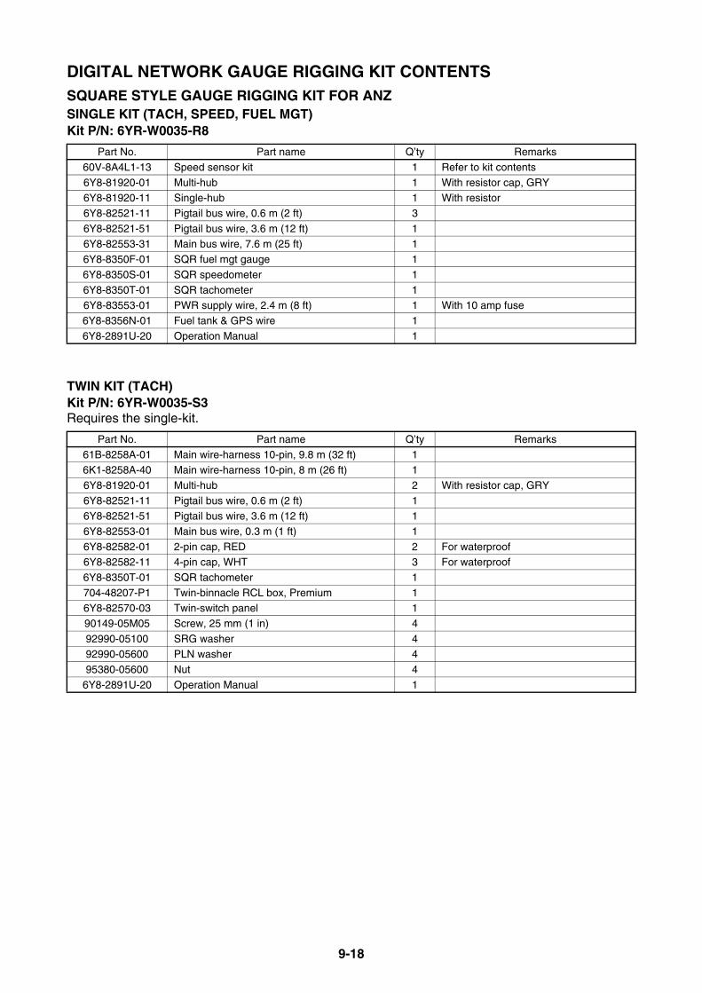
9-18
DIGITAL NETWORK GAUGE RIGGING KIT CONTENTSSQUARE STYLE GAUGE RIGGING KIT FOR ANZSINGLE KIT (TACH, SPEED, FUEL MGT)Kit P/N: 6YR-W0035-R8
TWIN KIT (TACH)Kit P/N: 6YR-W0035-S3Requires the single-kit.
Part No. Part name Q’ty Remarks
60V-8A4L1-13 Speed sensor kit 1 Refer to kit contents
6Y8-81920-01 Multi-hub 1 With resistor cap, GRY6Y8-81920-11 Single-hub 1 With resistor
6Y8-82521-11 Pigtail bus wire, 0.6 m (2 ft) 3
6Y8-82521-51 Pigtail bus wire, 3.6 m (12 ft) 16Y8-82553-31 Main bus wire, 7.6 m (25 ft) 1
6Y8-8350F-01 SQR fuel mgt gauge 1
6Y8-8350S-01 SQR speedometer 1
6Y8-8350T-01 SQR tachometer 16Y8-83553-01 PWR supply wire, 2.4 m (8 ft) 1 With 10 amp fuse
6Y8-8356N-01 Fuel tank & GPS wire 1
6Y8-2891U-20 Operation Manual 1
Part No. Part name Q’ty Remarks
61B-8258A-01 Main wire-harness 10-pin, 9.8 m (32 ft) 16K1-8258A-40 Main wire-harness 10-pin, 8 m (26 ft) 1
6Y8-81920-01 Multi-hub 2 With resistor cap, GRY
6Y8-82521-11 Pigtail bus wire, 0.6 m (2 ft) 16Y8-82521-51 Pigtail bus wire, 3.6 m (12 ft) 1
6Y8-82553-01 Main bus wire, 0.3 m (1 ft) 1
6Y8-82582-01 2-pin cap, RED 2 For waterproof6Y8-82582-11 4-pin cap, WHT 3 For waterproof
6Y8-8350T-01 SQR tachometer 1
704-48207-P1 Twin-binnacle RCL box, Premium 16Y8-82570-03 Twin-switch panel 1
90149-05M05 Screw, 25 mm (1 in) 4
92990-05100 SRG washer 492990-05600 PLN washer 4
95380-05600 Nut 4
6Y8-2891U-20 Operation Manual 1
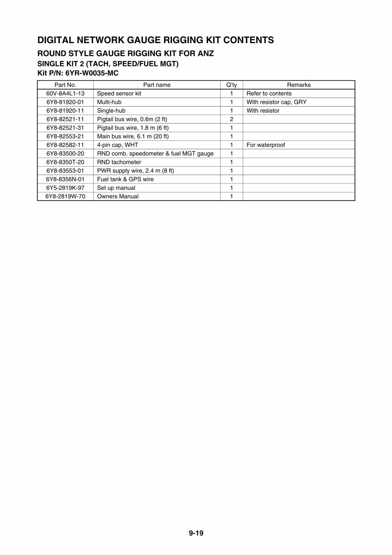
9-19
DIGITAL NETWORK GAUGE RIGGING KIT CONTENTSROUND STYLE GAUGE RIGGING KIT FOR ANZSINGLE KIT 2 (TACH, SPEED/FUEL MGT)Kit P/N: 6YR-W0035-MC
Part No. Part name Q’ty Remarks
60V-8A4L1-13 Speed sensor kit 1 Refer to contents
6Y8-81920-01 Multi-hub 1 With resistor cap, GRY6Y8-81920-11 Single-hub 1 With resistor
6Y8-82521-11 Pigtail bus wire, 0.6m (2 ft) 2
6Y8-82521-31 Pigtail bus wire, 1.8 m (6 ft) 16Y8-82553-21 Main bus wire, 6.1 m (20 ft) 1
6Y8-82582-11 4-pin cap, WHT 1 For waterproof
6Y8-83500-20 RND comb. speedometer & fuel MGT gauge 1
6Y8-8350T-20 RND tachometer 16Y8-83553-01 PWR supply wire, 2.4 m (8 ft) 1
6Y8-8356N-01 Fuel tank & GPS wire 1
6Y5-2819K-97 Set up manual 16Y8-2819W-70 Owners Manual 1

9-20
DIGITAL NETWORK GAUGE RIGGING KIT CONTENTSSQUARE STYLE GAUGE RIGGING KIT FOR JAPANSINGLE KIT 1 (TACH)Kit P/N: 6YR-W0035-U1
SINGLE KIT 2 (TACH, SPEED/FUEL MGT)Kit P/N: 6YR-W0035-V7
F350 SINGLE KIT (TACH, SPEED/ FUEL MGT)Kit P/N: 6X6-W0035-21
Part No. Part name Q’ty Remarks
6Y8-81920-01 Multi-hub 1 With resistor cap, GRY
6Y8-81920-11 Single-hub 1 With resistor6Y8-82521-21 Pigtail bus wire, 0.9 m (3 ft) 1
6Y8-82521-41 Pigtail bus wire, 2.7 m (9 ft) 1
6Y8-82553-21 Main bus wire, 6.1 m (20 ft) 16Y8-82582-11 4-pin cap, WHT 2 For waterproof
6Y8-8350T-01 SQR tachometer 1
6Y8-83553-01 PWR supply wire, 2.4 m (8 ft) 1 With 10 amp fuse
6Y8-2819U-01 Operation manual 1
Part No. Part name Q’ty Remarks
60V-8A4L1-13 Speed sensor kit 1 Refer to kit contents
6Y8-81920-01 Multi-hub 1 With resistor cap, GRY6Y8-81920-11 Single-hub 1 With resistor
6Y8-82521-21 Pigtail bus wire, 0.9 m (3 ft) 2
6Y8-82521-51 Pigtail bus wire, 3.6 m (12 ft) 16Y8-82553-31 Main bus wire, 7.5 m (25 ft) 1
6Y8-82582-11 4-pin cap, WHT 1 For waterproof
6Y8-83500-01 SQR comb. speedometer & fuel mgt gauge 16Y8-8350T-01 SQR tachometer 1
6Y8-83553-01 PWR supply wire, 2.4 m (8 ft) 1 With 10 amp fuse
6Y8-8356N-01 Fuel tank & GPS wire 16Y8-2819U-01 Operation manual 1
Part No. Part name Q’ty Remarks
6Y8-8350T-01 SQR Tachometer 16Y8-8356N-01 GPS/ Fuel tank wire 1
6Y8-83500-01 SQR Comb. Speed/ fuel mgt meter 1
6Y8-81920-01 Multi-hub 16Y8-85371-01 Resistor cap 1 Gray, 6-pin
6Y8-82521-21 Pigtail bus wire, 0.9 m (3 ft) 2
6Y8-82521-31 Pigtail bus wire, 1.8 m (6 ft) 16Y8-83553-01 PWR supply wire, 2.4 m (8 ft) 1 With 10 amp fuse
6R5-82570-06 Switch panel 1 Single
6X6-8258A-30 Main wire-harness, 10 m (32 ft) 1 16-pin6Y8-2819U-01 Operation manual 1 Japanese
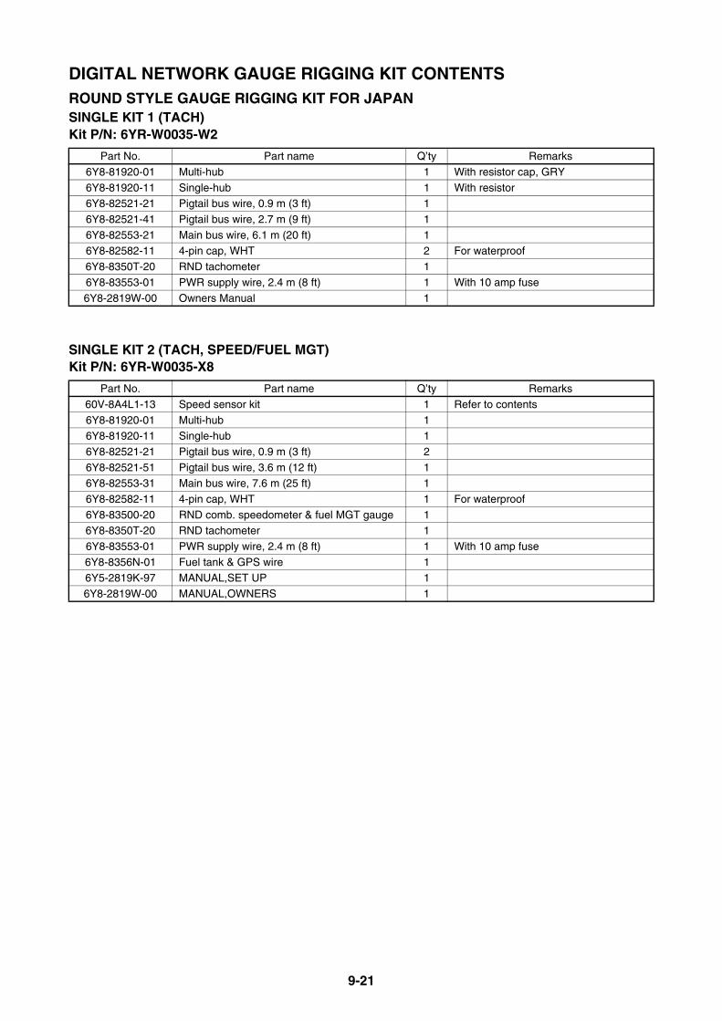
9-21
DIGITAL NETWORK GAUGE RIGGING KIT CONTENTSROUND STYLE GAUGE RIGGING KIT FOR JAPANSINGLE KIT 1 (TACH)Kit P/N: 6YR-W0035-W2
SINGLE KIT 2 (TACH, SPEED/FUEL MGT)Kit P/N: 6YR-W0035-X8
Part No. Part name Q’ty Remarks
6Y8-81920-01 Multi-hub 1 With resistor cap, GRY
6Y8-81920-11 Single-hub 1 With resistor6Y8-82521-21 Pigtail bus wire, 0.9 m (3 ft) 1
6Y8-82521-41 Pigtail bus wire, 2.7 m (9 ft) 1
6Y8-82553-21 Main bus wire, 6.1 m (20 ft) 16Y8-82582-11 4-pin cap, WHT 2 For waterproof
6Y8-8350T-20 RND tachometer 1
6Y8-83553-01 PWR supply wire, 2.4 m (8 ft) 1 With 10 amp fuse
6Y8-2819W-00 Owners Manual 1
Part No. Part name Q’ty Remarks
60V-8A4L1-13 Speed sensor kit 1 Refer to contents
6Y8-81920-01 Multi-hub 16Y8-81920-11 Single-hub 1
6Y8-82521-21 Pigtail bus wire, 0.9 m (3 ft) 2
6Y8-82521-51 Pigtail bus wire, 3.6 m (12 ft) 16Y8-82553-31 Main bus wire, 7.6 m (25 ft) 1
6Y8-82582-11 4-pin cap, WHT 1 For waterproof
6Y8-83500-20 RND comb. speedometer & fuel MGT gauge 16Y8-8350T-20 RND tachometer 1
6Y8-83553-01 PWR supply wire, 2.4 m (8 ft) 1 With 10 amp fuse
6Y8-8356N-01 Fuel tank & GPS wire 16Y5-2819K-97 MANUAL,SET UP 1
6Y8-2819W-00 MANUAL,OWNERS 1

9-22
IMMOBILIZER RIGGING KIT CONTENTSIMMOBILIZER KIT 1 (FOR US, ANZ, CRB)Kit P/N: 6Y8-W0035-83
IMMOBILIZER KIT 2 (FOR JPN)Kit P/N: 6Y8-W0035-92
SINGLE ENGINE GAUGE KIT FOR IMMOBILIZER (FOR EU, ANZ, JPN, GEN)P/N: 6Y8-W0035-A2 (w/ IG SW panel)
Part No. Part name Q’ty Remarks
6Y8-86254-22 Immobilizer unit 1 Conformed to local frequency band
90167-06M00 Screw 497880-06035 Screw 4
90201-06M30 Washer 8
95780-06300 Nut 46Y8-82521-11 Pigtail bus wire 1 0.3 m (1 ft)
6Y8-48277-00 Symbol graphic 4
6Y8-28107-94 Instruction 1
Part No. Part name Q’ty Remarks6Y8-86254-30 Immobilizer unit 1 Conformed to local frequency band
90167-06M00 Screw 4
97880-06035 Screw 490201-06M30 Washer 8
95780-06300 Nut 4
6Y8-82521-11 Pigtail bus wire 1 0.3 m (1 ft)6Y8-48277-00 Symbol graphic 3
6Y8-28107-94 Instruction 1
Part No. Part name Q’ty Remarks6Y8-8350T-01 SQR tachometer 1
6Y8-83500-01 SQR speed/fuel gauge 1
6Y8-81920-01 Multi-hub 2 w/ resistor6Y8-82553-01 Main bus wire, 0.3 m (1 ft) 1
6Y8-82582-11 4-pin waterproof cap 3 White
6Y8-82582-01 2-pin waterproof cap 1 Red6Y8-82521-11 Pigtail bus wire, 0.6 m (2 ft) 2
6Y8-82521-31 Pigtail bus wire, 1.8 m (6 ft) 1
6Y8-8356N-01 Fuel tank/ GPS wire 1 NMEA01836Y8-83553-01 PWR supply wire 1 w/ 10 amp fuse
6X6-82570-31 IG switch panel, single 1 OFF-ON-START
6X6-8258A-30 Main wire-harness, 10 m (33 ft) 1 16-pin6Y9-2819K-E0 Set up manual 1
6Y8-2819U-20 Operation Manual 1
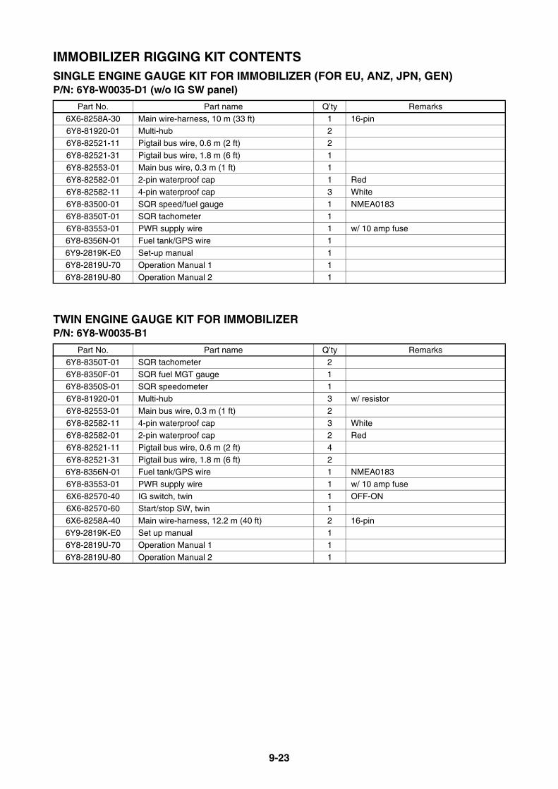
9-23
IMMOBILIZER RIGGING KIT CONTENTSSINGLE ENGINE GAUGE KIT FOR IMMOBILIZER (FOR EU, ANZ, JPN, GEN)P/N: 6Y8-W0035-D1 (w/o IG SW panel)
TWIN ENGINE GAUGE KIT FOR IMMOBILIZERP/N: 6Y8-W0035-B1
Part No. Part name Q’ty Remarks
6X6-8258A-30 Main wire-harness, 10 m (33 ft) 1 16-pin
6Y8-81920-01 Multi-hub 26Y8-82521-11 Pigtail bus wire, 0.6 m (2 ft) 2
6Y8-82521-31 Pigtail bus wire, 1.8 m (6 ft) 1
6Y8-82553-01 Main bus wire, 0.3 m (1 ft) 16Y8-82582-01 2-pin waterproof cap 1 Red
6Y8-82582-11 4-pin waterproof cap 3 White
6Y8-83500-01 SQR speed/fuel gauge 1 NMEA0183
6Y8-8350T-01 SQR tachometer 16Y8-83553-01 PWR supply wire 1 w/ 10 amp fuse
6Y8-8356N-01 Fuel tank/GPS wire 1
6Y9-2819K-E0 Set-up manual 16Y8-2819U-70 Operation Manual 1 1
6Y8-2819U-80 Operation Manual 2 1
Part No. Part name Q’ty Remarks6Y8-8350T-01 SQR tachometer 2
6Y8-8350F-01 SQR fuel MGT gauge 1
6Y8-8350S-01 SQR speedometer 16Y8-81920-01 Multi-hub 3 w/ resistor
6Y8-82553-01 Main bus wire, 0.3 m (1 ft) 2
6Y8-82582-11 4-pin waterproof cap 3 White6Y8-82582-01 2-pin waterproof cap 2 Red
6Y8-82521-11 Pigtail bus wire, 0.6 m (2 ft) 4
6Y8-82521-31 Pigtail bus wire, 1.8 m (6 ft) 26Y8-8356N-01 Fuel tank/GPS wire 1 NMEA0183
6Y8-83553-01 PWR supply wire 1 w/ 10 amp fuse
6X6-82570-40 IG switch, twin 1 OFF-ON6X6-82570-60 Start/stop SW, twin 1
6X6-8258A-40 Main wire-harness, 12.2 m (40 ft) 2 16-pin
6Y9-2819K-E0 Set up manual 16Y8-2819U-70 Operation Manual 1 1
6Y8-2819U-80 Operation Manual 2 1
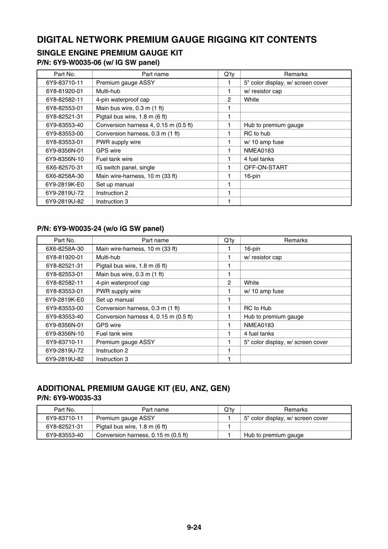
9-24
DIGITAL NETWORK PREMIUM GAUGE RIGGING KIT CONTENTSSINGLE ENGINE PREMIUM GAUGE KITP/N: 6Y9-W0035-06 (w/ IG SW panel)
P/N: 6Y9-W0035-24 (w/o IG SW panel)
ADDITIONAL PREMIUM GAUGE KIT (EU, ANZ, GEN)P/N: 6Y9-W0035-33
Part No. Part name Q’ty Remarks
6Y9-83710-11 Premium gauge ASSY 1 5" color display, w/ screen cover
6Y8-81920-01 Multi-hub 1 w/ resistor cap6Y8-82582-11 4-pin waterproof cap 2 White
6Y8-82553-01 Main bus wire, 0.3 m (1 ft) 1
6Y8-82521-31 Pigtail bus wire, 1.8 m (6 ft) 16Y9-83553-40 Conversion harness 4, 0.15 m (0.5 ft) 1 Hub to premium gauge
6Y9-83553-00 Conversion harness, 0.3 m (1 ft) 1 RC to hub
6Y8-83553-01 PWR supply wire 1 w/ 10 amp fuse
6Y9-8356N-01 GPS wire 1 NMEA01836Y9-8356N-10 Fuel tank wire 1 4 fuel tanks
6X6-82570-31 IG switch panel, single 1 OFF-ON-START
6X6-8258A-30 Main wire-harness, 10 m (33 ft) 1 16-pin6Y9-2819K-E0 Set up manual 1
6Y9-2819U-72 Instruction 2 1
6Y9-2819U-82 Instruction 3 1
Part No. Part name Q’ty Remarks
6X6-8258A-30 Main wire-harness, 10 m (33 ft) 1 16-pin
6Y8-81920-01 Multi-hub 1 w/ resistor cap6Y8-82521-31 Pigtail bus wire, 1.8 m (6 ft) 1
6Y8-82553-01 Main bus wire, 0.3 m (1 ft) 1
6Y8-82582-11 4-pin waterproof cap 2 White6Y8-83553-01 PWR supply wire 1 w/ 10 amp fuse
6Y9-2819K-E0 Set up manual 1
6Y9-83553-00 Conversion harness, 0.3 m (1 ft) 1 RC to Hub6Y9-83553-40 Conversion harness 4, 0.15 m (0.5 ft) 1 Hub to premium gauge
6Y9-8356N-01 GPS wire 1 NMEA0183
6Y9-8356N-10 Fuel tank wire 1 4 fuel tanks6Y9-83710-11 Premium gauge ASSY 1 5" color display, w/ screen cover
6Y9-2819U-72 Instruction 2 1
6Y9-2819U-82 Instruction 3 1
Part No. Part name Q’ty Remarks
6Y9-83710-11 Premium gauge ASSY 1 5" color display, w/ screen cover
6Y8-82521-31 Pigtail bus wire, 1.8 m (6 ft) 16Y9-83553-40 Conversion harness, 0.15 m (0.5 ft) 1 Hub to premium gauge
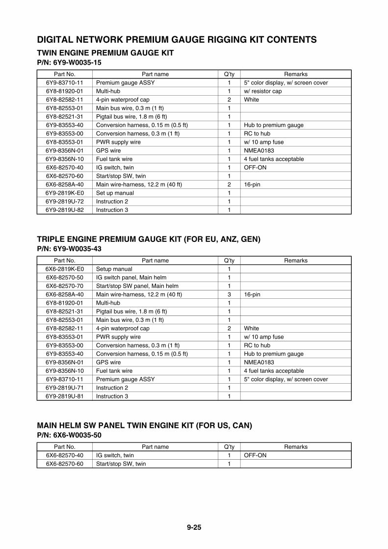
9-25
DIGITAL NETWORK PREMIUM GAUGE RIGGING KIT CONTENTSTWIN ENGINE PREMIUM GAUGE KITP/N: 6Y9-W0035-15
TRIPLE ENGINE PREMIUM GAUGE KIT (FOR EU, ANZ, GEN)P/N: 6Y9-W0035-43
MAIN HELM SW PANEL TWIN ENGINE KIT (FOR US, CAN)P/N: 6X6-W0035-50
Part No. Part name Q’ty Remarks
6Y9-83710-11 Premium gauge ASSY 1 5" color display, w/ screen cover
6Y8-81920-01 Multi-hub 1 w/ resistor cap6Y8-82582-11 4-pin waterproof cap 2 White
6Y8-82553-01 Main bus wire, 0.3 m (1 ft) 1
6Y8-82521-31 Pigtail bus wire, 1.8 m (6 ft) 16Y9-83553-40 Conversion harness, 0.15 m (0.5 ft) 1 Hub to premium gauge
6Y9-83553-00 Conversion harness, 0.3 m (1 ft) 1 RC to hub
6Y8-83553-01 PWR supply wire 1 w/ 10 amp fuse
6Y9-8356N-01 GPS wire 1 NMEA01836Y9-8356N-10 Fuel tank wire 1 4 fuel tanks acceptable
6X6-82570-40 IG switch, twin 1 OFF-ON
6X6-82570-60 Start/stop SW, twin 16X6-8258A-40 Main wire-harness, 12.2 m (40 ft) 2 16-pin
6Y9-2819K-E0 Set up manual 1
6Y9-2819U-72 Instruction 2 16Y9-2819U-82 Instruction 3 1
Part No. Part name Q’ty Remarks
6X6-2819K-E0 Setup manual 16X6-82570-50 IG switch panel, Main helm 1
6X6-82570-70 Start/stop SW panel, Main helm 1
6X6-8258A-40 Main wire-harness, 12.2 m (40 ft) 3 16-pin6Y8-81920-01 Multi-hub 1
6Y8-82521-31 Pigtail bus wire, 1.8 m (6 ft) 1
6Y8-82553-01 Main bus wire, 0.3 m (1 ft) 16Y8-82582-11 4-pin waterproof cap 2 White
6Y8-83553-01 PWR supply wire 1 w/ 10 amp fuse
6Y9-83553-00 Conversion harness, 0.3 m (1 ft) 1 RC to hub6Y9-83553-40 Conversion harness, 0.15 m (0.5 ft) 1 Hub to premium gauge
6Y9-8356N-01 GPS wire 1 NMEA0183
6Y9-8356N-10 Fuel tank wire 1 4 fuel tanks acceptable6Y9-83710-11 Premium gauge ASSY 1 5" color display, w/ screen cover
6Y9-2819U-71 Instruction 2 1
6Y9-2819U-81 Instruction 3 1
Part No. Part name Q’ty Remarks
6X6-82570-40 IG switch, twin 1 OFF-ON
6X6-82570-60 Start/stop SW, twin 1
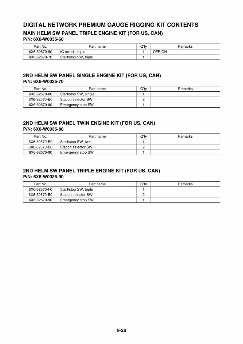
9-26
DIGITAL NETWORK PREMIUM GAUGE RIGGING KIT CONTENTSMAIN HELM SW PANEL TRIPLE ENGINE KIT (FOR US, CAN)P/N: 6X6-W0035-60
2ND HELM SW PANEL SINGLE ENGINE KIT (FOR US, CAN)P/N: 6X6-W0035-70
2ND HELM SW PANEL TWIN ENGINE KIT (FOR US, CAN)P/N: 6X6-W0035-80
2ND HELM SW PANEL TRIPLE ENGINE KIT (FOR US, CAN)P/N: 6X6-W0035-90
Part No. Part name Q’ty Remarks
6X6-82570-50 IG switch, triple 1 OFF-ON
6X6-82570-70 Start/stop SW, triple 1
Part No. Part name Q’ty Remarks
6X6-82570-80 Start/stop SW, single 1
6X6-82570-B0 Station selector SW 2
6X6-82570-90 Emergency stop SW 1
Part No. Part name Q’ty Remarks
6X6-82570-E0 Start/stop SW, twin 1
6X6-82570-B0 Station selector SW 26X6-82570-90 Emergency stop SW 1
Part No. Part name Q’ty Remarks
6X6-82570-F0 Start/stop SW, triple 16X6-82570-B0 Station selector SW 2
6X6-82570-90 Emergency stop SW 1

9-27
OTHER RIGGING KIT CONTENTSTILT LIMIT SWITCH KIT (FOR US, CA, EU, ANZ, RUS, JPN)P/N: 63P-825EY-01Applicable models:
Kit contents:
* For installation, see the service manual and/or installation manual.
TILT LIMIT SWITCH KIT 2 (FOR US, CA, EU, ANZ, JP, RUS, TUR)P/N: 6CE-825EY-00Applicable models:
Kit contents:
* For installation, see the service manual and/or installation manual.
Global model F/FL115A
US/CA model F/LF115AGlobal model F/FL115B F/FL150A F150C F165A F175A F200D F/FL200F F225D
US/CA/ANZ model F/LF115B F/LF150A VF150A VF200LA F/LF200B VF225LA
Global model F250C F225G F250F F275AUS/CA/ANZ model VF250LA
Part No. Part name Q’ty Remarks63P-825E0-01 Tilt limit SW ASSY 1
97595-06516 Bolt w/ washer 2
90159-05059 Screw 190387-05004 Collar 1
90465-11M10 Clamp 5
Global model F/FL200G F/FL225F F/FL250D F/FL300BUS/CA/ANZ model F/LF200CA F/LF225CA F/LF250CA F/LF300CA
Part No. Part name Q’ty Remarks
6CE-825E0-00 Tilt limit SW ASSY 1
97595-06516 Bolt w/ washer 290159-05059 Screw 1
90387-05004 Collar 1
90465-11M10 Clamp 890465-13M18 Clamp 1
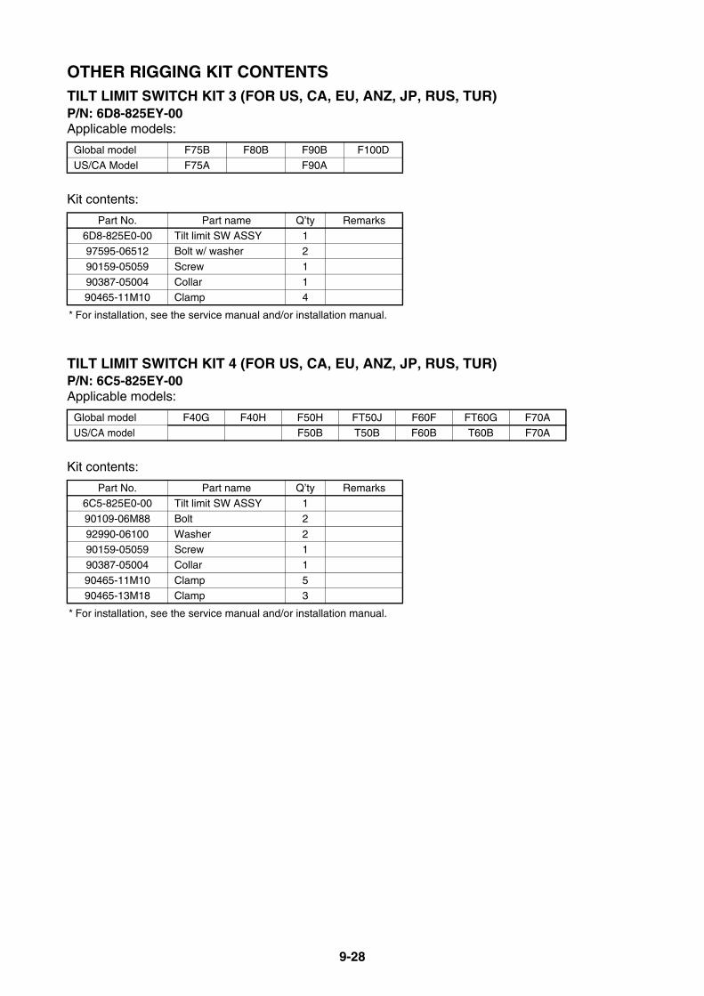
9-28
OTHER RIGGING KIT CONTENTSTILT LIMIT SWITCH KIT 3 (FOR US, CA, EU, ANZ, JP, RUS, TUR)P/N: 6D8-825EY-00Applicable models:
Kit contents:
* For installation, see the service manual and/or installation manual.
TILT LIMIT SWITCH KIT 4 (FOR US, CA, EU, ANZ, JP, RUS, TUR)P/N: 6C5-825EY-00Applicable models:
Kit contents:
* For installation, see the service manual and/or installation manual.
Global model F75B F80B F90B F100D
US/CA Model F75A F90A
Part No. Part name Q’ty Remarks6D8-825E0-00 Tilt limit SW ASSY 1
97595-06512 Bolt w/ washer 2
90159-05059 Screw 1
90387-05004 Collar 190465-11M10 Clamp 4
Global model F40G F40H F50H FT50J F60F FT60G F70AUS/CA model F50B T50B F60B T60B F70A
Part No. Part name Q’ty Remarks6C5-825E0-00 Tilt limit SW ASSY 1
90109-06M88 Bolt 2
92990-06100 Washer 290159-05059 Screw 1
90387-05004 Collar 1
90465-11M10 Clamp 590465-13M18 Clamp 3

9-29
OTHER RIGGING KIT CONTENTSLIGHTING COIL KIT (FOR EU, CA, JPN)P/N: 6BX-W8130-A0Applicable models:
Kit contents:
* For installation, see the service manual and/or service guide.
Global model F4B F5A F6C
US/CA Model F4A F6A
Part No. Part name Q’ty Remarks6BX-81949-00 Wire lead 1
6BX-81960-00 Rectifier/ regulator 1
6BX-82388-00 Plate 1
6BX-82581-00 Stay 16BX-85510-A0 Stator ASSY 1
6BX-85550-A0 Rotor ASSY 1
90109-06M80 Bolt 190464-30009 Clamp 1
90465-08371 Clamp 1
97595-06516 Bolt 297595-06520 Bolt 3

9-30
2014 YEAR MODELS MANUFACTURE STARTING SERIAL NUMBERS4-STROKE ENGINES
Model name Model code
Prefix code
Starting serial number Remarks
Global USA/CANF2AMH 6S7 6S7 1005576 France made, For JPN
F2.5AMH F2.5MHA 69M 69M 1088426 France made
F4BMH F4MHA 6BV 6BV 1026809 France made
F5AMH 6BW 6BW 1018717 France made
F6CMH F6MHA 6BX 6BX 1034054 France made
F8CMH F8MHA60R 60R 1041295
France made
F8CWH France made, For JPN
FT8DE
60S 60S 1027287
France made, For EUR
FT8DEP France made, For EUR
FT8DMH France made
F9.9JE F9.9EB
6DR 6AUK 1036634F9.9JEH F9.9EHB For USA/CAN
F9.9JMH F9.9MHB
F9.9JWH For JPN
FT9.9LE T9.9EB
6EA 6AVK 1024398
FT9.9LEHP T9.9PHB For USA/CAN
FT9.9LEP T9.9PB
FT9.9LMH T9.9MHB
FT9.9LWH T9.9EHB
F9.9HMH6CA 6CAK 1005533
For EUR
F9.9HE For EUR
F15CE
6AG 6AGK 1037915
F15CEH F15EHA
F15CEHP F15PHA
F15CEP For EUR
F15CMH F15MHA
F15CWH For JPN
F20BE F20EA
6AH 6AHK 1048600
F20BEH F20EHA
F20BEHP F20PHA
F20BEP F20PA
F20BMH F20MHA
F20BWH For JPN
F20CE6AJ 6AJK 1002846
For CHN
F20CMH
F20BMH 6BY 6BY 1003301 Brazil made, For BRA
F20DET 6DN 6DNK 1000373 For EUR
FT25FET T25A 6BL 6BLK 1002536
F25DE F25EA
6BP 6BPK 1026254
F25DEH F25EHA For USA/CAN
F25DEHD F25EHB For USA/CAN
F25DEHT
F25DET F25A
F25DMH F25MHA
F25DMHD F25MHB For USA/CAN
F25DWH For JPN
F25DWHD For JPN

9-31
2014 YEAR MODELS MANUFACTURE STARTING SERIAL NUMBERS4-STROKE ENGINES
Model name Model code
Prefix code
Starting serial number Remarks
Global USA/CANF30BEHD F30EHA
6BT 6BT 1009010F30BEHT
F30BET F30A
F40HET 6AK 6AK 1012069
F40FED F40EA
6BG 6BG 1040682F40FEHD F40EHA
F40FEHT
F40FET F40A
F40GET 6CY 6CY 1002797
F40FED
6EU 6EU 1000389
Brazil made, For BRA
F40FEHD Brazil made, For BRA
F40FET Brazil made, For BRA
F50DET 60A 60A 1002454
FT50CEHD61S 64J 1015476
FT50CET
F50HED
6C1 6C1 1055284
For EUR
F50HEHD
F50HEHT F50HB
F50HET F50B
FT50JET T50B 6C2 6C2 1018429
F60FEHT F60HB6C5 6C5 1061672
F60FET F60B
F60FET 6DP 6DP 1002067 Brazil made, For BRA
FT60GEHD
6C6 6C6 1023541
For MEX
FT60GEHT For MEX
FT60GET T60B
F70AET F70A 6CJ 6CJ 1037285
F75BET F75A 6D6 62P 1014815
F75CED6BC 6BC 1003376
For Carib
F75CEHD
F80BET 6D7 6D7 1016275
F90BET F90A 6D8 61P 1069391
F90BETL 6EJ 6EJ 1001231 Brazil made, For BRA
F95AET 6S0 6S0 1000785 For JPN
F100BET 60C 60C 1009582
F100DET 6D9 6D9 1023702
F115AEHT68V 68V 1163115
For MEX
F115AET F115A
FL115AET LF115A 68W 68W 1005922

9-32
2014 YEAR MODELS MANUFACTURE STARTING SERIAL NUMBERS4-STROKE ENGINES
Model name Model code
Prefix code
Starting serial number Remarks
Global USA/CAN/ANZF115BET F115B
6EK 6EK 1000001F115BEHT For MEX
FL115BET LF115B 6EL 6EL 1000001
F150AET F150A 63P 63P 1140779
FL150AET LF150A 64P 64P 1016405
F150BET 6BM 6BM 1003126
FL150BET 6BN 6BN 1000600
F150CET VF150A 6EH 6EH 1000872 For USA/CAN/ANZ
F165AET 6FC 6FC 1000071 For JPN
F175AET F175A 6FA 6FA 1000001
F200CET F200A 6AL 6AL 1004892
FL200CET LF200A 6AM 6AM 1000562
F200DET VF200A 6CD 6CD 1002622 For USA/CAN/ANZ
F200FET F200B 6DA 6DA 1006240
FL200FET LF200B 6DB 6DB 1000765
F200BET 6S1 6S1 1004677
FL200BET 6S2 6S2 1001608
F200GET F200CA 6DV 6DV 1001141
FL200GET LF200CA 6DW 6DW 1000557
F225BET F225A 6AS 6AS 1003396
FL225BET 6AT 6AT 1000359
F225CET 6BB 6BB 1001543 For EUR
F225DET VF225A 6CC 6CC 1002267 For USA/CAN/ANZ
F225FET F225CA 6CL 6CL 1002385
FL225FET LF225CA 6CM 6CM 1000533
F225GET 6DM 6DM 1000070 For JPN
F250CET VF250A 6CB 6CB 1007982 For USA/CAN/ANZ
F250DET F250CA 6CG 6CG 1006697
FL250DET LF250CA 6CH 6CH 1001787
F250FET 6DL 6DL 1000079 For JPN
F250GET 6DX 6DX 1002557
FL250GET 6DY 6DY 1001284
F250AET F250A 6P2 6P2 1039404
FL250AET LF250A 6P3 6P3 1014845
F275A 6DK 6DK 1000136 For JPN
F300BET F300CA 6CE 6CE 1014239
FL300BET LF300CA 6CF 6CF 1005385
F350AET F350CB 6AW 6AW 1009009
FL350AET LF350CB 6AX 6AX 1005581

9-33
2014 YEAR MODELS MANUFACTURE STARTING SERIAL NUMBERS2-STROKE ENGINES
Model name Model code
Prefix code
Starting serial number Remarks
Global USA/CAN2CMH 6F8 6F8K 1071399
3AMH 6L5 6L5K 1035921
4ACMH 6E0 6E0K 1026831
5CMH 6E36E3K 1084331
5CSMH 6E4
6CMH 6M8 6M8 1015526 France made
8CMH 6N0 6N0 1042678 France made
E8DMH 677 677K 1018665
EK8DMH 680 680K 1010147
9.9FMH 63V 682K 1062391
9.9GMHS 63V 63VK 1000001 For RUS
E9.9DMH 6B3 6B3K 1014378
EK9.9DMH 6B7 6B7K 1011580 For IND
EK9.9JMH 6B9 6B9K 1003122 For LKA
15FMH 63W 684K 1130190
15FMH 65D 65D 1103751 Brazil made, For BRA
E15DMH 6B4 6B4K 1204505
EK15DMH 6B8 6B8K 1005549
EK15PMH 6C0 6C0K 1005152 For LKA
20DMH 6L3 6L3K 1011499 For ANZ
25BMH
69R61RK 1062123
25BW
25BWC For RUS
E25BMH 69P
EK25BMH 69T 62CK 1004180
25BMH 69U 69U 1016526 Brazil made, For BRA
25XMH 69X 69XK 1000971 For ANZ
25NWC
6L2 6L2K 1053553
For ANZ
25NMH For ANZ
25NMHO
EK25CMH 6S6 6S6K 1001034 For LKA
E30HMH 60B
61TK 1086443
For MYS
30HMH
69S30HW
30HWC For RUS
30HWH
30DETO
6CT 6J8K 101336130DEO For RUS
30DMH For ANZ
30DMHO
E/40XMH
66T 66TK 1168221E/40XW
E40XWH
E/40XWT
40XMH67T 67T 1111026
Brazil made, For BRA
40XW Brazil made, For BRA
EK40GMH 6F5 6F5K 1020760
E40GMH6F6 6F6K 1096304
E40GWH For YEM

9-34
2014 YEAR MODELS MANUFACTURE STARTING SERIAL NUMBERS2-STROKE ENGINES
Model name Model code
Prefix code
Starting serial number Remarks
Global USA/CAN40VMHD
63B
6H4K 1024190
For ANZ
40VMHO For EUR
40VEO 63C
40VETO63D
For ANZ
40VWHTO For ANZ
EK40JMH 6H9 6H9K 1005002 For LKA
E40JMH
6J4 6J4K 1047813E40JW
E40JWH
E48CMH 696 670K 1014744
50HET
62X
6H5K 1032930
For ANZ
50HETO
50HWHTO For ANZ
50HMHD62W
For ANZ
50HMHDO For RUS
50HMHO 63G
55DEHD 63S 63S 1002505 For IRN
55BED697
663K 101052355BET
E55CMH 6A3
60FET6CU 6H2K 1015815
60FETO
E60HMHD
69D 6K5K 1044473E60HWD
E60HWHD
70BETO 6H3 6H3K 1015848
75CETO 67P
692 1074242
For EUR
75AED
69275AEHD
75AET
E75BMHD
85AED
688 688 104133785AEHD
85AET
90AETO 6H1 6H1 1048689
E115AE
61U
6E5 1034424
E115AET
E115AMH
E115AWH
115BET 6E5 For CHN
115CETO 6N6
130BETO 6N7 6L1 1005581
140BET 6F3 6F3 1002714
150AET 6G4 6G4 1024158
Z150QETO VZ150TR 68J 6J9 1015622 For USA
L150AET 6K0 6K0 1001374 For MNE
200AET 60H 6G6 1054973
L200AET 60J 6K1 1010822
250GETO 6S3 6S3 1003192

9-35
2014 YEAR MODELS MANUFACTURE STARTING SERIAL NUMBERS2-STROKE ENGINES
Model name Model code
Prefix code
Starting serial number Remarks
Global USA/CANL250GETO 6S4 6S4 1002031

Produced in JapanMar. 2014 – ABE(E)
Related Documents