1 RIDUTTORI AD ASSI PARALLELI PARALLEL SHAFT GEAR UNITS Descrizione Description Capitolo Chapter 1 Designazione Designation 2 2 Forme costruttive Versions 3 3 Opzioni Options 3 4 Dispositivo antiretro Anti-run back device 4 5 Lubrificazione Lubrication 4 6 Posizioni di montaggio Mounting positions 5 7 Prestazioni nominali Rating chart 6 8 Dimensioni d'ingombro Installation drawings 13 9 Perno macchina Customer's shaft 28 10 Installazione riduttore con calettatore Installation of the shrink disc 29 11 Calcolo del carico radiale Calculation of radial load 30 12 Predisposizioni attacco motore Motor adapters 31 RAP Revisions Refer to page 32 for the catalogue revision index. Check on www.bonfiglioli.com for latest revision of each catalogue. Revisioni L’indice di revisione del catalogo è riportato a pag. 32. Nel sito www.bonfiglioli.com sono disponibili i cataloghi con le revisioni aggiornate.

Welcome message from author
This document is posted to help you gain knowledge. Please leave a comment to let me know what you think about it! Share it to your friends and learn new things together.
Transcript
1
RIDUTTORI AD ASSI PARALLELIPARALLEL SHAFT GEAR UNITS
Descrizione DescriptionCapitoloChapter
1 Designazione Designation 2
2 Forme costruttive Versions 3
3 Opzioni Options 3
4 Dispositivo antiretro Anti-run back device 4
5 Lubrificazione Lubrication 4
6 Posizioni di montaggio Mounting positions 5
7 Prestazioni nominali Rating chart 6
8 Dimensioni d'ingombro Installation drawings 13
9 Perno macchina Customer's shaft 28
10 Installazione riduttore con calettatore Installation of the shrink disc 29
11 Calcolo del carico radiale Calculation of radial load 30
12 Predisposizioni attacco motore Motor adapters 31
RAP
Revisions
Refer to page 32 for the catalogue revision index.
Check on www.bonfiglioli.com for latest revision of each
catalogue.
Revisioni
L’indice di revisione del catalogo è riportato a pag. 32.
Nel sito www.bonfiglioli.com sono disponibili i cataloghi con le
revisioni aggiornate.
2
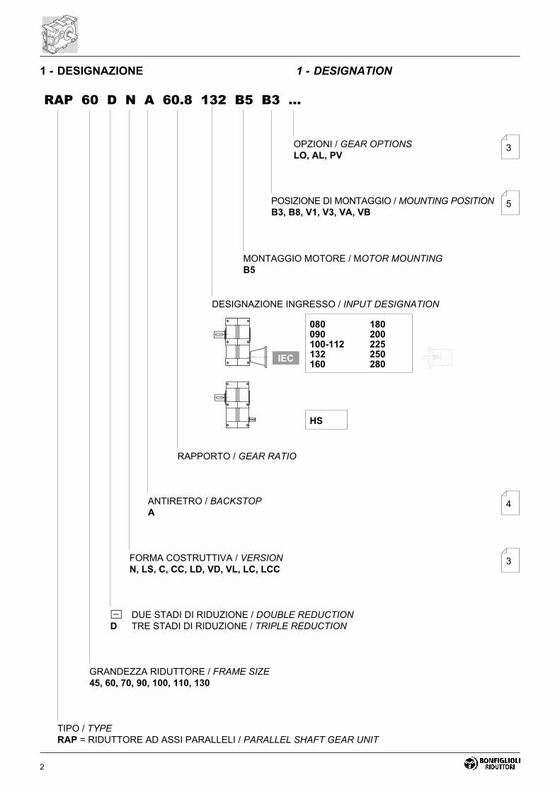
1 - DESIGNAZIONE 1 - DESIGNATION
RAP 60 D N A 60.8 132 B5 B3 ...
OPZIONI / GEAR OPTIONS
LO, AL, PV3
POSIZIONE DI MONTAGGIO / MOUNTING POSITION
B3, B8, V1, V3, VA, VB
MONTAGGIO MOTORE / MOTOR MOUNTING
B5
DESIGNAZIONE INGRESSO / INPUT DESIGNATION
RAPPORTO / GEAR RATIO
ANTIRETRO / BACKSTOP
A
FORMA COSTRUTTIVA / VERSION
N, LS, C, CC, LD, VD, VL, LC, LCC
5
� DUE STADI DI RIDUZIONE / DOUBLE REDUCTION
D TRE STADI DI RIDUZIONE / TRIPLE REDUCTION
GRANDEZZA RIDUTTORE / FRAME SIZE
45, 60, 70, 90, 100, 110, 130
TIPO / TYPE
RAP = RIDUTTORE AD ASSI PARALLELI / PARALLEL SHAFT GEAR UNIT
3
4
080 180090 200100-112 225132 250160 280
HS
IEC
–

3
2 - FORME COSTRUTTIVE 2 - VERSIONS
�� �� �� ��
�
��
�
��
��
��
��
��
���
Default
3 - OPZIONI 3 - OPTIONS
LO
I riduttori sono riempiti in fabbrica con carica di lubrifi-
cante sintetico del tipo correntemente utilizzato da
BONFIGLIOLI RIDUTTORI, in quantità dipendente
dalla posizione di montaggio specificata.
PV
Dotazione di anelli di tenuta in Viton®.
AL
Specifica del dispositivo antiretro con rotazione libera
antioraria.
LO
Gearbox is factory filled with synthetic lubricant of the
type currently used by BONFIGLIOLI RIDUTTORI ac-
cording to the mounting position specified.
PV
Oil seals from Viton®compound.
AL
Backstop is set to allow shaft rotation in the CCW di-
rection.
4
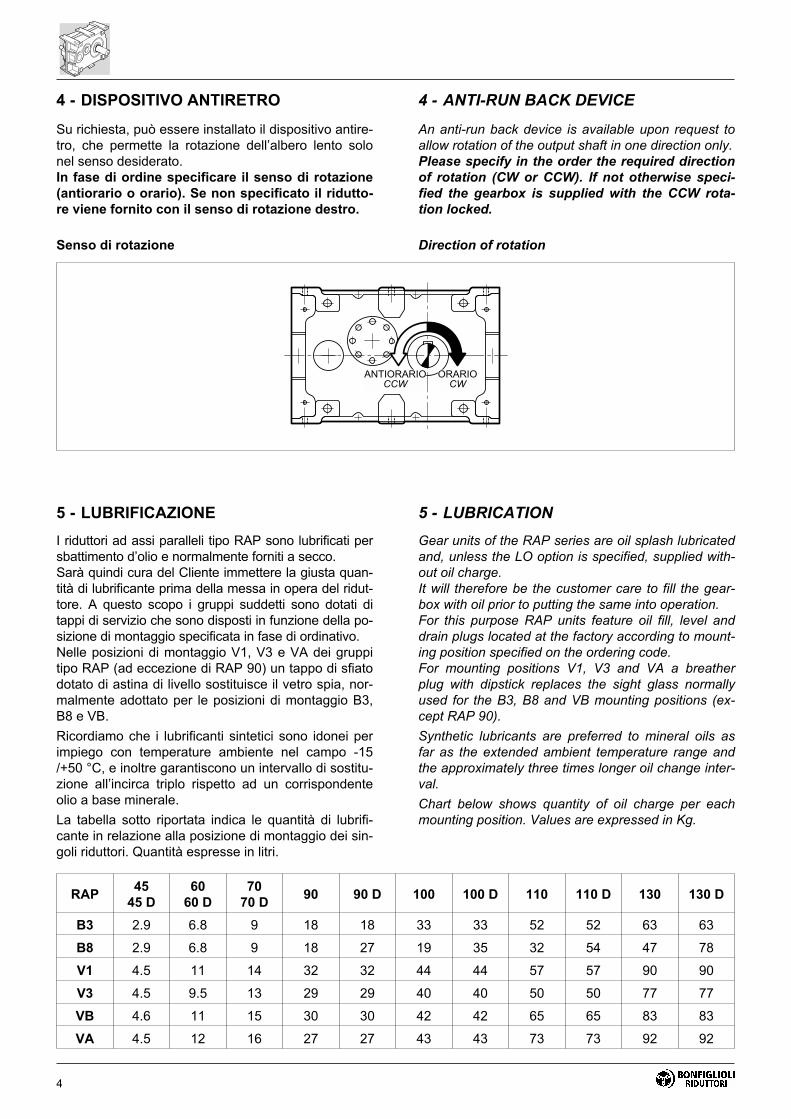
Su richiesta, può essere installato il dispositivo antire-
tro, che permette la rotazione dell’albero lento solo
nel senso desiderato.
In fase di ordine specificare il senso di rotazione
(antiorario o orario). Se non specificato il ridutto-
re viene fornito con il senso di rotazione destro.
Senso di rotazione
An anti-run back device is available upon request to
allow rotation of the output shaft in one direction only.
Please specify in the order the required direction
of rotation (CW or CCW). If not otherwise speci-
fied the gearbox is supplied with the CCW rota-
tion locked.
Direction of rotation
4 - DISPOSITIVO ANTIRETRO 4 - ANTI-RUN BACK DEVICE
�������������
��������
5 - LUBRIFICAZIONE 5 - LUBRICATION
I riduttori ad assi paralleli tipo RAP sono lubrificati per
sbattimento d’olio e normalmente forniti a secco.
Sarà quindi cura del Cliente immettere la giusta quan-
tità di lubrificante prima della messa in opera del ridut-
tore. A questo scopo i gruppi suddetti sono dotati di
tappi di servizio che sono disposti in funzione della po-
sizione di montaggio specificata in fase di ordinativo.
Nelle posizioni di montaggio V1, V3 e VA dei gruppi
tipo RAP (ad eccezione di RAP 90) un tappo di sfiato
dotato di astina di livello sostituisce il vetro spia, nor-
malmente adottato per le posizioni di montaggio B3,
B8 e VB.
Ricordiamo che i lubrificanti sintetici sono idonei per
impiego con temperature ambiente nel campo -15
/+50 °C, e inoltre garantiscono un intervallo di sostitu-
zione all’incirca triplo rispetto ad un corrispondente
olio a base minerale.
La tabella sotto riportata indica le quantità di lubrifi-
cante in relazione alla posizione di montaggio dei sin-
goli riduttori. Quantità espresse in litri.
Gear units of the RAP series are oil splash lubricated
and, unless the LO option is specified, supplied with-
out oil charge.
It will therefore be the customer care to fill the gear-
box with oil prior to putting the same into operation.
For this purpose RAP units feature oil fill, level and
drain plugs located at the factory according to mount-
ing position specified on the ordering code.
For mounting positions V1, V3 and VA a breather
plug with dipstick replaces the sight glass normally
used for the B3, B8 and VB mounting positions (ex-
cept RAP 90).
Synthetic lubricants are preferred to mineral oils as
far as the extended ambient temperature range and
the approximately three times longer oil change inter-
val.
Chart below shows quantity of oil charge per each
mounting position. Values are expressed in Kg.
RAP45
45 D
60
60 D
70
70 D90 90 D 100 100 D 110 110 D 130 130 D
B3 2.9 6.8 9 18 18 33 33 52 52 63 63
B8 2.9 6.8 9 18 27 19 35 32 54 47 78
V1 4.5 11 14 32 32 44 44 57 57 90 90
V3 4.5 9.5 13 29 29 40 40 50 50 77 77
VB 4.6 11 15 30 30 42 42 65 65 83 83
VA 4.5 12 16 27 27 43 43 73 73 92 92

5
6 - POSIZIONI DI MONTAGGIO 6 - MOUNTING POSITIONS
Unitamente alle posizioni di montaggio V1, V3 e VA
indicare la velocità in entrata se n1 � 500 min-1.
Along with the mounting position V1, V3 and VA it is
recommended that the input speed n1 is also reported, if
lower than 500 min-1.
�� ��
�� ��
�� ��
6
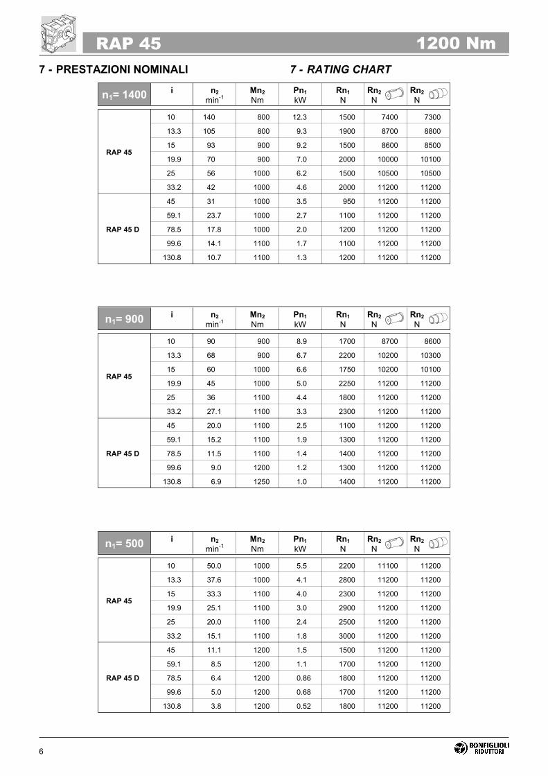
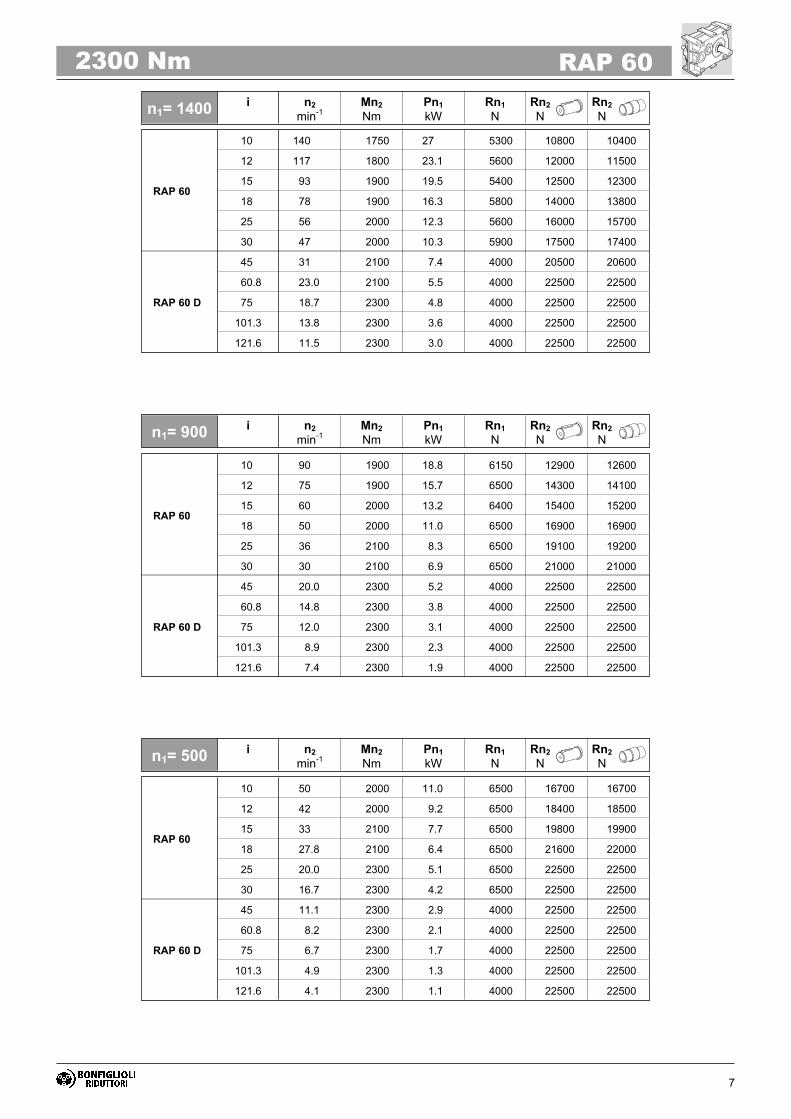
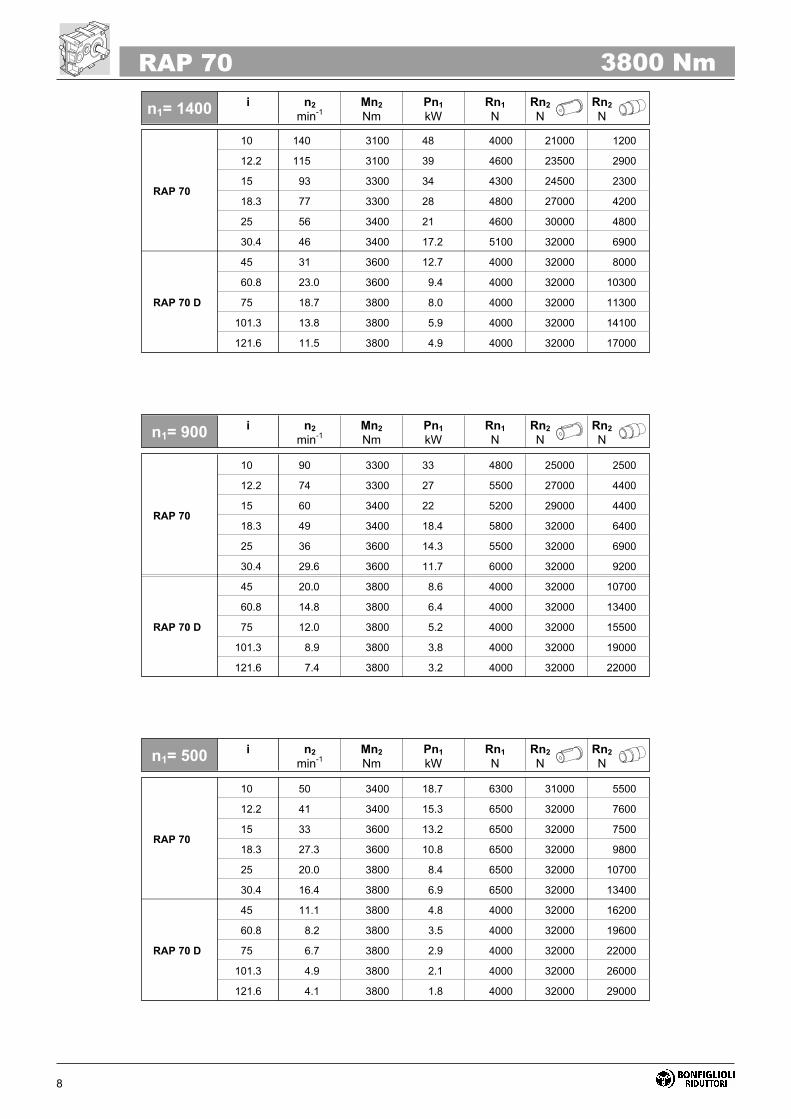
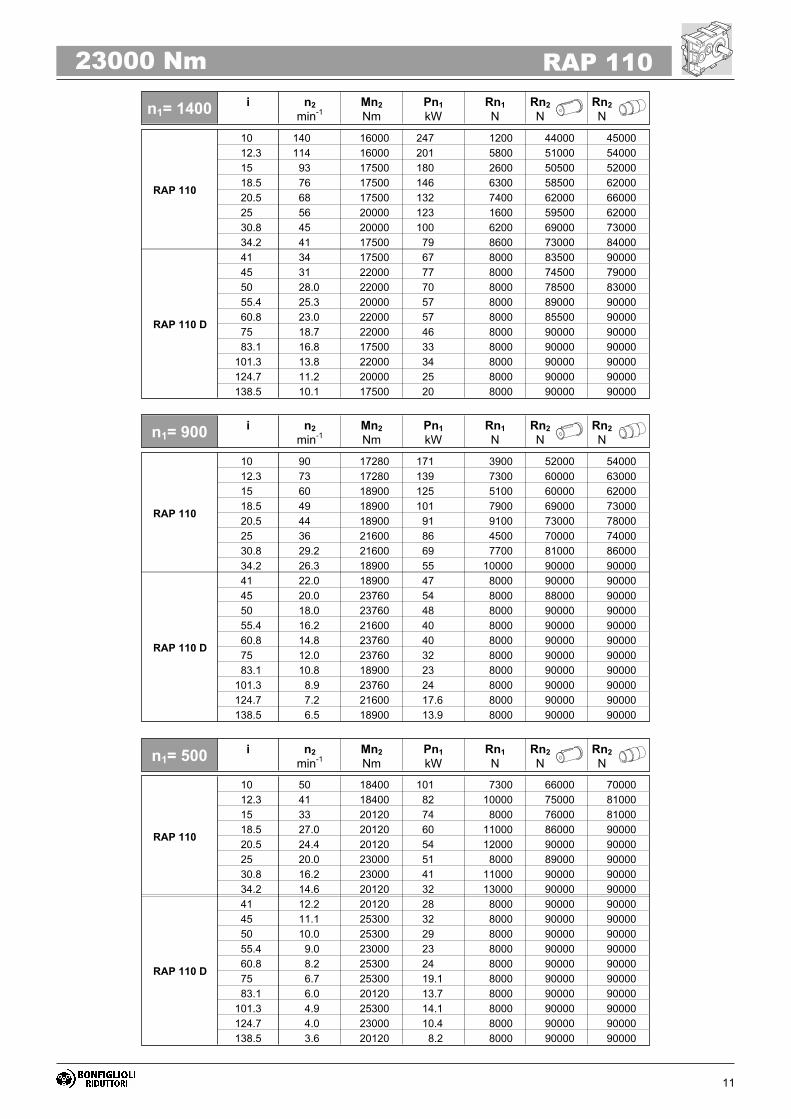
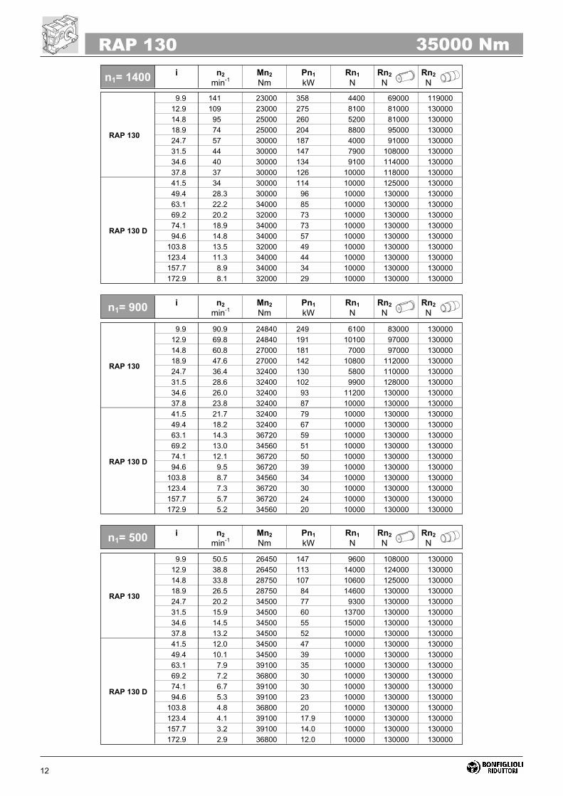
7 - PRESTAZIONI NOMINALI 7 - RATING CHART
n1= 900i n2
min-1
Mn2
Nm
Pn1
kW
Rn1
N
Rn2
N
Rn2
N
RAP 45
10 140 800 12.3 1500 7400 7300
13.3 105 800 9.3 1900 8700 8800
15 93 900 9.2 1500 8600 8500
19.9 70 900 7.0 2000 10000 10100
25 56 1000 6.2 1500 10500 10500
33.2 42 1000 4.6 2000 11200 11200
RAP 45 D
45 31 1000 3.5 950 11200 11200
59.1 23.7 1000 2.7 1100 11200 11200
78.5 17.8 1000 2.0 1200 11200 11200
99.6 14.1 1100 1.7 1100 11200 11200
130.8 10.7 1100 1.3 1200 11200 11200
RAP 45 1200 Nm
RAP 45
10 90 900 8.9 1700 8700 8600
13.3 68 900 6.7 2200 10200 10300
15 60 1000 6.6 1750 10200 10100
19.9 45 1000 5.0 2250 11200 11200
25 36 1100 4.4 1800 11200 11200
33.2 27.1 1100 3.3 2300 11200 11200
RAP 45 D
45 20.0 1100 2.5 1100 11200 11200
59.1 15.2 1100 1.9 1300 11200 11200
78.5 11.5 1100 1.4 1400 11200 11200
99.6 9.0 1200 1.2 1300 11200 11200
130.8 6.9 1250 1.0 1400 11200 11200
RAP 45
10 50.0 1000 5.5 2200 11100 11200
13.3 37.6 1000 4.1 2800 11200 11200
15 33.3 1100 4.0 2300 11200 11200
19.9 25.1 1100 3.0 2900 11200 11200
25 20.0 1100 2.4 2500 11200 11200
33.2 15.1 1100 1.8 3000 11200 11200
RAP 45 D
45 11.1 1200 1.5 1500 11200 11200
59.1 8.5 1200 1.1 1700 11200 11200
78.5 6.4 1200 0.86 1800 11200 11200
99.6 5.0 1200 0.68 1700 11200 11200
130.8 3.8 1200 0.52 1800 11200 11200
n1= 500i n2
min-1
Mn2
Nm
Pn1
kW
Rn1
N
Rn2
N
Rn2
N
n1= 1400i n2
min-1
Mn2
Nm
Pn1
kW
Rn1
N
Rn2
N
Rn2
N
7
RAP 602300 Nm
RAP 60
10 140 1750 27 5300 10800 10400
12 117 1800 23.1 5600 12000 11500
15 93 1900 19.5 5400 12500 12300
18 78 1900 16.3 5800 14000 13800
25 56 2000 12.3 5600 16000 15700
30 47 2000 10.3 5900 17500 17400
RAP 60 D
45 31 2100 7.4 4000 20500 20600
60.8 23.0 2100 5.5 4000 22500 22500
75 18.7 2300 4.8 4000 22500 22500
101.3 13.8 2300 3.6 4000 22500 22500
121.6 11.5 2300 3.0 4000 22500 22500
RAP 60
10 90 1900 18.8 6150 12900 12600
12 75 1900 15.7 6500 14300 14100
15 60 2000 13.2 6400 15400 15200
18 50 2000 11.0 6500 16900 16900
25 36 2100 8.3 6500 19100 19200
30 30 2100 6.9 6500 21000 21000
RAP 60 D
45 20.0 2300 5.2 4000 22500 22500
60.8 14.8 2300 3.8 4000 22500 22500
75 12.0 2300 3.1 4000 22500 22500
101.3 8.9 2300 2.3 4000 22500 22500
121.6 7.4 2300 1.9 4000 22500 22500
RAP 60
10 50 2000 11.0 6500 16700 16700
12 42 2000 9.2 6500 18400 18500
15 33 2100 7.7 6500 19800 19900
18 27.8 2100 6.4 6500 21600 22000
25 20.0 2300 5.1 6500 22500 22500
30 16.7 2300 4.2 6500 22500 22500
RAP 60 D
45 11.1 2300 2.9 4000 22500 22500
60.8 8.2 2300 2.1 4000 22500 22500
75 6.7 2300 1.7 4000 22500 22500
101.3 4.9 2300 1.3 4000 22500 22500
121.6 4.1 2300 1.1 4000 22500 22500
n1= 900i n2
min-1
Mn2
Nm
Pn1
kW
Rn1
N
Rn2
N
Rn2
N
n1= 500i n2
min-1
Mn2
Nm
Pn1
kW
Rn1
N
Rn2
N
Rn2
N
n1= 1400i n2
min-1
Mn2
Nm
Pn1
kW
Rn1
N
Rn2
N
Rn2
N
8
RAP 70
10 140 3100 48 4000 21000 1200
12.2 115 3100 39 4600 23500 2900
15 93 3300 34 4300 24500 2300
18.3 77 3300 28 4800 27000 4200
25 56 3400 21 4600 30000 4800
30.4 46 3400 17.2 5100 32000 6900
RAP 70 D
45 31 3600 12.7 4000 32000 8000
60.8 23.0 3600 9.4 4000 32000 10300
75 18.7 3800 8.0 4000 32000 11300
101.3 13.8 3800 5.9 4000 32000 14100
121.6 11.5 3800 4.9 4000 32000 17000
RAP 70 3800 Nm
RAP 70
10 90 3300 33 4800 25000 2500
12.2 74 3300 27 5500 27000 4400
15 60 3400 22 5200 29000 4400
18.3 49 3400 18.4 5800 32000 6400
25 36 3600 14.3 5500 32000 6900
30.4 29.6 3600 11.7 6000 32000 9200
RAP 70 D
45 20.0 3800 8.6 4000 32000 10700
60.8 14.8 3800 6.4 4000 32000 13400
75 12.0 3800 5.2 4000 32000 15500
101.3 8.9 3800 3.8 4000 32000 19000
121.6 7.4 3800 3.2 4000 32000 22000
RAP 70
10 50 3400 18.7 6300 31000 5500
12.2 41 3400 15.3 6500 32000 7600
15 33 3600 13.2 6500 32000 7500
18.3 27.3 3600 10.8 6500 32000 9800
25 20.0 3800 8.4 6500 32000 10700
30.4 16.4 3800 6.9 6500 32000 13400
RAP 70 D
45 11.1 3800 4.8 4000 32000 16200
60.8 8.2 3800 3.5 4000 32000 19600
75 6.7 3800 2.9 4000 32000 22000
101.3 4.9 3800 2.1 4000 32000 26000
121.6 4.1 3800 1.8 4000 32000 29000
n1= 900i n2
min-1
Mn2
Nm
Pn1
kW
Rn1
N
Rn2
N
Rn2
N
n1= 500i n2
min-1
Mn2
Nm
Pn1
kW
Rn1
N
Rn2
N
Rn2
N
n1= 1400i n2
min-1
Mn2
Nm
Pn1
kW
Rn1
N
Rn2
N
Rn2
N

9
RAP 907000 Nm
RAP 90
10 140 5500 85 3400 36500 2100
12.5 112 5500 68 4500 40500 4300
15 93 6100 63 3600 41500 3000
18.8 74 6100 50 4700 46000 5600
25 56 6300 39 4100 50500 6800
31.3 45 6300 31 5100 55500 9700
RAP 90 D
45 31 6600 23 5000 63000 11900
60.8 23.0 6600 17.2 5000 65000 15500
75 18.7 7000 14.8 5000 65000 16900
101.3 13.8 7000 10.9 5000 65000 21000
121.6 11.5 7000 9.1 5000 65000 26000
RAP 90
10 90 6100 60 4000 42000 3300
12.5 72 6100 48 5300 47000 5900
15 60 6300 42 4700 49000 6100
18.8 48 6300 33 5900 54000 9000
25 36 6600 26 5100 59000 10300
31.3 28.8 6600 21 6200 65000 13600
RAP 90 D
45 20.0 7000 15.8 5000 65000 16000
60.8 14.8 7000 11.7 5000 65000 20000
75 12.0 7000 9.5 5000 65000 23000
101.3 8.9 7000 7.0 5000 65000 28000
121.6 7.4 7000 5.9 5000 65000 33000
RAP 90
10 50 6300 34.7 5900 53000 7900
12.5 40 6300 27.7 7200 58000 10900
15 33 6600 24.2 6500 61000 11100
18.8 26.6 6600 19.3 7700 65000 15000
25 20.0 7000 15.4 6900 65000 16000
31.3 16.0 7000 12.3 8000 65000 20000
RAP 90 D
45 11.1 7000 8.8 5000 65000 25000
60.8 8.2 7000 6.5 5000 65000 30000
75 6.7 7000 5.3 5000 65000 34000
101.3 4.9 7000 3.9 5000 65000 40000
121.6 4.1 7000 3.3 5000 65000 45000
n1= 900i n2
min-1
Mn2
Nm
Pn1
kW
Rn1
N
Rn2
N
Rn2
N
n1= 500i n2
min-1
Mn2
Nm
Pn1
kW
Rn1
N
Rn2
N
Rn2
N
n1= 1400i n2
min-1
Mn2
Nm
Pn1
kW
Rn1
N
Rn2
N
Rn2
N

10
RAP 100
10.0 140 11000 170 5400 33500 33500
12.3 114 11000 138 7400 38000 39000
15.0 93 13000 134 4900 37000 36000
18.5 76 13000 108 7100 42000 42000
20.5 68 11000 83 9200 48500 51000
25.0 56 13500 83 5800 46500 47000
30.8 45 13500 68 7700 52000 54000
34.2 41 11000 50 10000 60000 64000
RAP 100 D
41.0 34 11000 42 7000 64500 70000
45.0 31 14500 51 7000 58500 61000
50.0 28.0 14500 46 7000 61500 64000
55.4 25.3 13500 39 7000 67000 71000
60.8 23.0 14500 38 7000 67000 70000
75.0 18.7 14500 31 7000 73500 75000
83.1 16.8 11000 21 7000 75000 75000
101.3 13.8 14500 23 7000 75000 75000
124.7 11.2 13500 17.1 7000 75000 75000
138.5 10.1 11000 12.6 7000 75000 75000
RAP 100 15000 Nm
RAP 100
10.0 90 11880 118 6800 40000 40000
12.3 73 11880 96 9000 45000 46000
15.0 60 14040 93 6400 44000 44000
18.5 49 14040 75 8700 49000 50000
20.5 44 11880 57 10000 57000 60000
25.0 36 14580 58 7200 55000 56000
30.8 29.2 14580 47 9400 61000 63000
34.2 26.3 11880 34 10000 70000 75000
RAP 100 D
41.0 22.0 11880 29 7000 75000 75000
45.0 20.0 15660 35 7000 69000 72000
50.0 18.0 15660 32 7000 72000 75000
55.4 16.2 14580 27 7000 75000 75000
60.8 14.8 15660 26 7000 75000 75000
75.0 12.0 15660 21 7000 75000 75000
83.1 10.8 11880 14.5 7000 75000 75000
101.3 8.9 15660 15.7 7000 75000 75000
124.7 7.2 14580 11.9 7000 75000 75000
138.5 6.5 11880 8.7 7000 75000 75000
RAP 100
10.0 50 12650 70 9600 51000 52000
12.3 41 12650 57 10000 56000 59000
15.0 33 14950 55 9100 56000 57000
18.5 27.0 14950 44 10000 62000 65000
20.5 24.4 12650 34 10000 71000 75000
25.0 20.0 15520 34 10000 69000 72000
30.8 16.2 15520 28 10000 75000 75000
34.2 14.6 12650 20 10000 75000 75000
RAP 100 D
41.0 12.2 12650 17.4 7000 75000 75000
45.0 11.1 16670 20.9 7000 75000 75000
50.0 10.0 16670 18.8 7000 75000 75000
55.4 9.0 15520 15.8 7000 75000 75000
60.8 8.2 16670 15.5 7000 75000 75000
75.0 6.7 16670 12.6 7000 75000 75000
83.1 6.0 12650 8.6 7000 75000 75000
101.3 4.9 16670 9.3 7000 75000 75000
124.7 4.0 15520 7.0 7000 75000 75000
138.5 3.6 12650 5.2 7000 75000 75000
n1= 900i n2
min-1
Mn2
Nm
Pn1
kW
Rn1
N
Rn2
N
Rn2
N
n1= 500i n2
min-1
Mn2
Nm
Pn1
kW
Rn1
N
Rn2
N
Rn2
N
n1= 1400i n2
min-1
Mn2
Nm
Pn1
kW
Rn1
N
Rn2
N
Rn2
N
11
RAP 11023000 Nm
RAP 110
10 140 16000 247 1200 44000 45000
12.3 114 16000 201 5800 51000 54000
15 93 17500 180 2600 50500 52000
18.5 76 17500 146 6300 58500 62000
20.5 68 17500 132 7400 62000 66000
25 56 20000 123 1600 59500 62000
30.8 45 20000 100 6200 69000 73000
34.2 41 17500 79 8600 73000 84000
RAP 110 D
41 34 17500 67 8000 83500 90000
45 31 22000 77 8000 74500 79000
50 28.0 22000 70 8000 78500 83000
55.4 25.3 20000 57 8000 89000 90000
60.8 23.0 22000 57 8000 85500 90000
75 18.7 22000 46 8000 90000 90000
83.1 16.8 17500 33 8000 90000 90000
101.3 13.8 22000 34 8000 90000 90000
124.7 11.2 20000 25 8000 90000 90000
138.5 10.1 17500 20 8000 90000 90000
RAP 110
10 90 17280 171 3900 52000 54000
12.3 73 17280 139 7300 60000 63000
15 60 18900 125 5100 60000 62000
18.5 49 18900 101 7900 69000 73000
20.5 44 18900 91 9100 73000 78000
25 36 21600 86 4500 70000 74000
30.8 29.2 21600 69 7700 81000 86000
34.2 26.3 18900 55 10000 90000 90000
RAP 110 D
41 22.0 18900 47 8000 90000 90000
45 20.0 23760 54 8000 88000 90000
50 18.0 23760 48 8000 90000 90000
55.4 16.2 21600 40 8000 90000 90000
60.8 14.8 23760 40 8000 90000 90000
75 12.0 23760 32 8000 90000 90000
83.1 10.8 18900 23 8000 90000 90000
101.3 8.9 23760 24 8000 90000 90000
124.7 7.2 21600 17.6 8000 90000 90000
138.5 6.5 18900 13.9 8000 90000 90000
RAP 110
10 50 18400 101 7300 66000 70000
12.3 41 18400 82 10000 75000 81000
15 33 20120 74 8000 76000 81000
18.5 27.0 20120 60 11000 86000 90000
20.5 24.4 20120 54 12000 90000 90000
25 20.0 23000 51 8000 89000 90000
30.8 16.2 23000 41 11000 90000 90000
34.2 14.6 20120 32 13000 90000 90000
RAP 110 D
41 12.2 20120 28 8000 90000 90000
45 11.1 25300 32 8000 90000 90000
50 10.0 25300 29 8000 90000 90000
55.4 9.0 23000 23 8000 90000 90000
60.8 8.2 25300 24 8000 90000 90000
75 6.7 25300 19.1 8000 90000 90000
83.1 6.0 20120 13.7 8000 90000 90000
101.3 4.9 25300 14.1 8000 90000 90000
124.7 4.0 23000 10.4 8000 90000 90000
138.5 3.6 20120 8.2 8000 90000 90000
n1= 900i n2
min-1
Mn2
Nm
Pn1
kW
Rn1
N
Rn2
N
Rn2
N
n1= 500i n2
min-1
Mn2
Nm
Pn1
kW
Rn1
N
Rn2
N
Rn2
N
n1= 1400i n2
min-1
Mn2
Nm
Pn1
kW
Rn1
N
Rn2
N
Rn2
N
12
RAP 130
9.9 141 23000 358 4400 69000 119000
12.9 109 23000 275 8100 81000 130000
14.8 95 25000 260 5200 81000 130000
18.9 74 25000 204 8800 95000 130000
24.7 57 30000 187 4000 91000 130000
31.5 44 30000 147 7900 108000 130000
34.6 40 30000 134 9100 114000 130000
37.8 37 30000 126 10000 118000 130000
RAP 130 D
41.5 34 30000 114 10000 125000 130000
49.4 28.3 30000 96 10000 130000 130000
63.1 22.2 34000 85 10000 130000 130000
69.2 20.2 32000 73 10000 130000 130000
74.1 18.9 34000 73 10000 130000 130000
94.6 14.8 34000 57 10000 130000 130000
103.8 13.5 32000 49 10000 130000 130000
123.4 11.3 34000 44 10000 130000 130000
157.7 8.9 34000 34 10000 130000 130000
172.9 8.1 32000 29 10000 130000 130000
RAP 130 35000 Nm
RAP 130
9.9 90.9 24840 249 6100 83000 130000
12.9 69.8 24840 191 10100 97000 130000
14.8 60.8 27000 181 7000 97000 130000
18.9 47.6 27000 142 10800 112000 130000
24.7 36.4 32400 130 5800 110000 130000
31.5 28.6 32400 102 9900 128000 130000
34.6 26.0 32400 93 11200 130000 130000
37.8 23.8 32400 87 10000 130000 130000
RAP 130 D
41.5 21.7 32400 79 10000 130000 130000
49.4 18.2 32400 67 10000 130000 130000
63.1 14.3 36720 59 10000 130000 130000
69.2 13.0 34560 51 10000 130000 130000
74.1 12.1 36720 50 10000 130000 130000
94.6 9.5 36720 39 10000 130000 130000
103.8 8.7 34560 34 10000 130000 130000
123.4 7.3 36720 30 10000 130000 130000
157.7 5.7 36720 24 10000 130000 130000
172.9 5.2 34560 20 10000 130000 130000
RAP 130
9.9 50.5 26450 147 9600 108000 130000
12.9 38.8 26450 113 14000 124000 130000
14.8 33.8 28750 107 10600 125000 130000
18.9 26.5 28750 84 14600 130000 130000
24.7 20.2 34500 77 9300 130000 130000
31.5 15.9 34500 60 13700 130000 130000
34.6 14.5 34500 55 15000 130000 130000
37.8 13.2 34500 52 10000 130000 130000
RAP 130 D
41.5 12.0 34500 47 10000 130000 130000
49.4 10.1 34500 39 10000 130000 130000
63.1 7.9 39100 35 10000 130000 130000
69.2 7.2 36800 30 10000 130000 130000
74.1 6.7 39100 30 10000 130000 130000
94.6 5.3 39100 23 10000 130000 130000
103.8 4.8 36800 20 10000 130000 130000
123.4 4.1 39100 17.9 10000 130000 130000
157.7 3.2 39100 14.0 10000 130000 130000
172.9 2.9 36800 12.0 10000 130000 130000
n1= 900i n2
min-1
Mn2
Nm
Pn1
kW
Rn1
N
Rn2
N
Rn2
N
n1= 500i n2
min-1
Mn2
Nm
Pn1
kW
Rn1
N
Rn2
N
Rn2
N
n1= 1400i n2
min-1
Mn2
Nm
Pn1
kW
Rn1
N
Rn2
N
Rn2
N

13
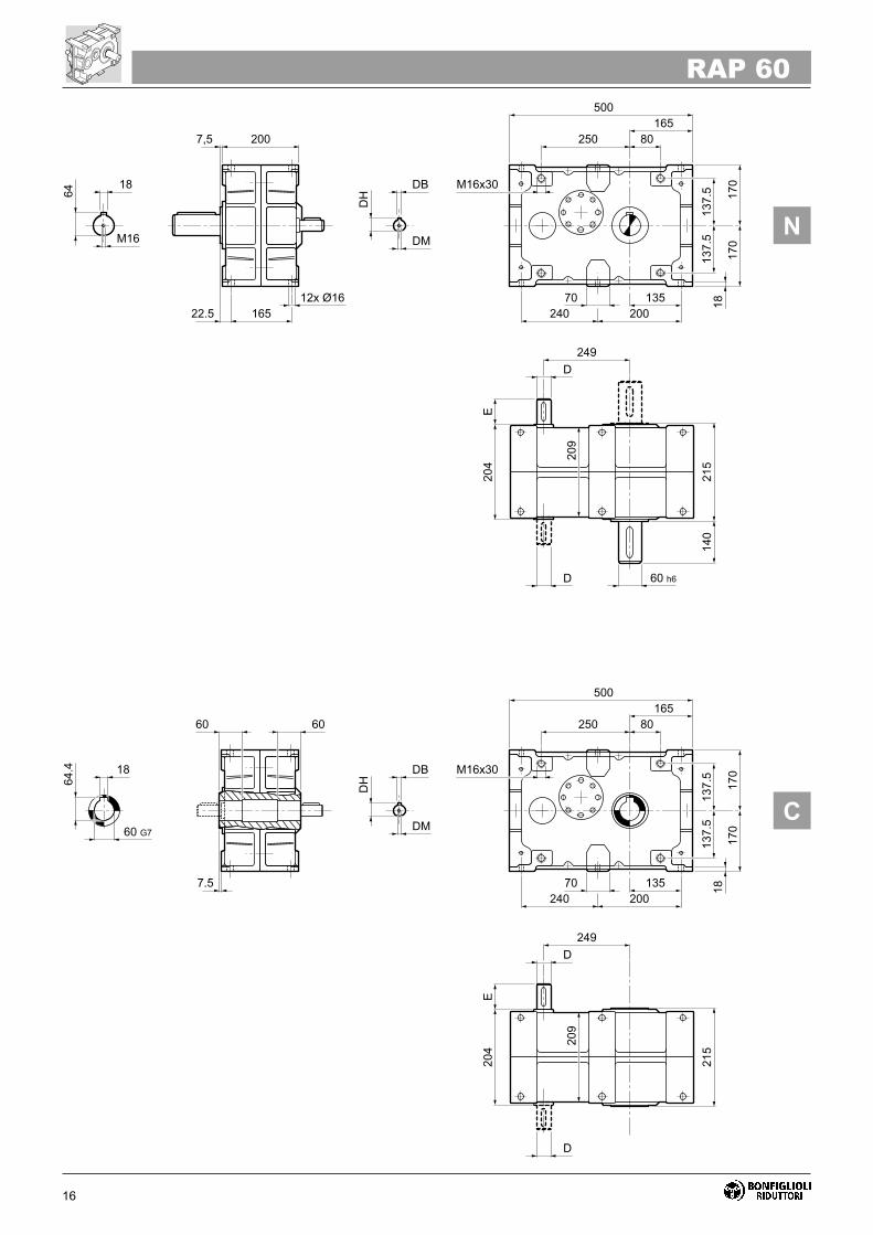
8 - DIMENSIONI D'INGOMBRO 8 - INSTALLATION DRAWINGS

14
���
��� ���
��� �����
��
�����
�� ������
��
��
����
���
���
��
��
��
��
����
�
����
���
�
��
��
��
������
�
��
��
��
��� �����
��
�����
�� ������
��
��
����
���
���
�����
����
����
���
�
��
��
�
��
�
��
RAP 45

15
RAP 45
����
�
��
��� �����
��
�����
�� ������
��
��
����
���
���
��
��
� ����
� ���
��
���
�
���
�
�
����
���
�
��
��
�
Z
INPUT RAP 45 - RAP 45 D
080 251
090 251
100/112 263
132 283
D h6 DB DH DM E
RAP 45 24 8 27 M8 50 42
RAP 45 D 19 6 21.5 M6 40 45
16
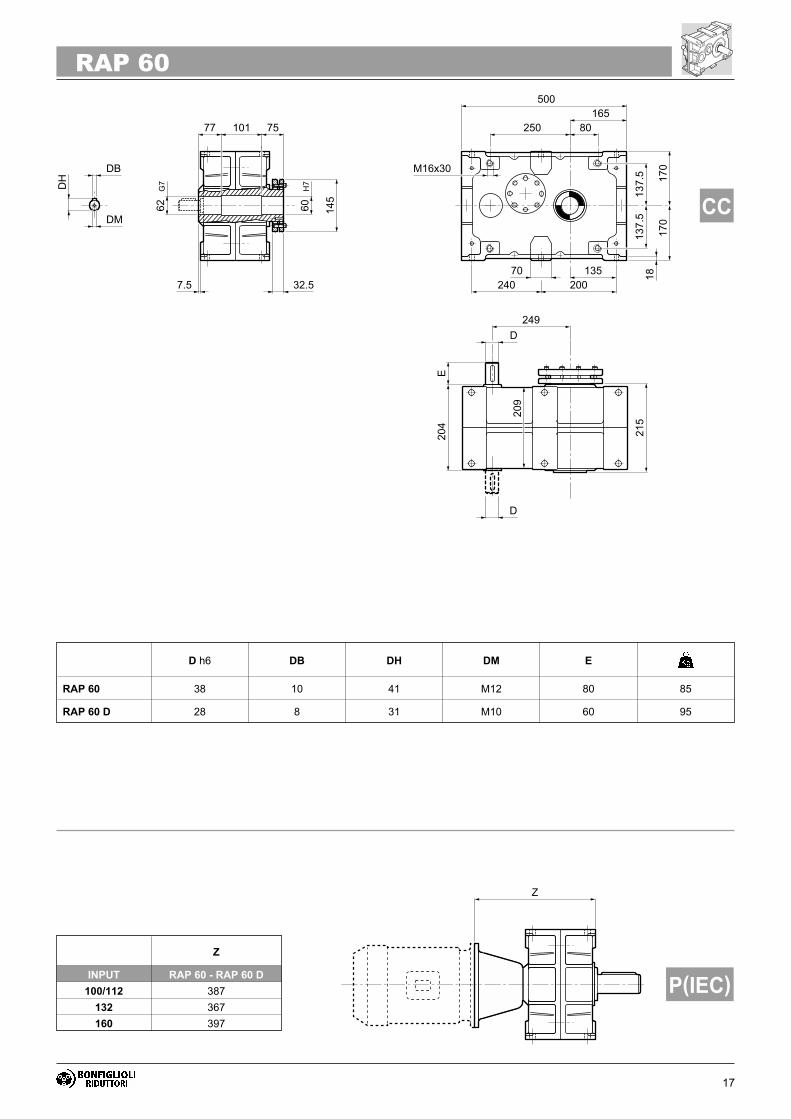
RAP 60
���
��� �������
� ����
�
�����
� ����
����
���
���
����
��
��
��
��
��
���
��
�
���
�
�
�
��
��
�����
�
��
��
��
� ����
�
�����
� ����
����
���
���
����
��
��
����
����
���
�
�
�
��
�
�
���
�
17
RAP 60
����
�
��
� ����
�
�����
� ����
����
���
���
����
��
��
��
��
�� ��
��� ���
��
��
�
��
�
���
���
�
�
�
��
�
Z
INPUT RAP 60 - RAP 60 D
100/112 387
132 367
160 397
D h6 DB DH DM E
RAP 60 38 10 41 M12 80 85
RAP 60 D 28 8 31 M10 60 95

18
RAP 70
�
��� �����
�� ����
��
�����
� �������
���
���
��
��
��
��
��
��
���
����
�
���
�
�
�
�
��
�����
�
��
��
��
�� ����
��
�����
� �������
���
���
��
��
��
����
����
���
�
�
�
�
�
�
�
�

19
RAP 70
����
�
��
�� ����
��
�����
� �������
���
���
��
��
��
��
��
��
� �
� ��
��
��
�
��
�
���
���
�
�
�
�
�
Z
INPUT RAP 70 - RAP 70 D
100/112 405
132 385
160 415
180 415
D h6 DB DH DM E
RAP 70 38 10 41 M12 80 112
RAP 70 D 28 8 31 M10 60 125

20
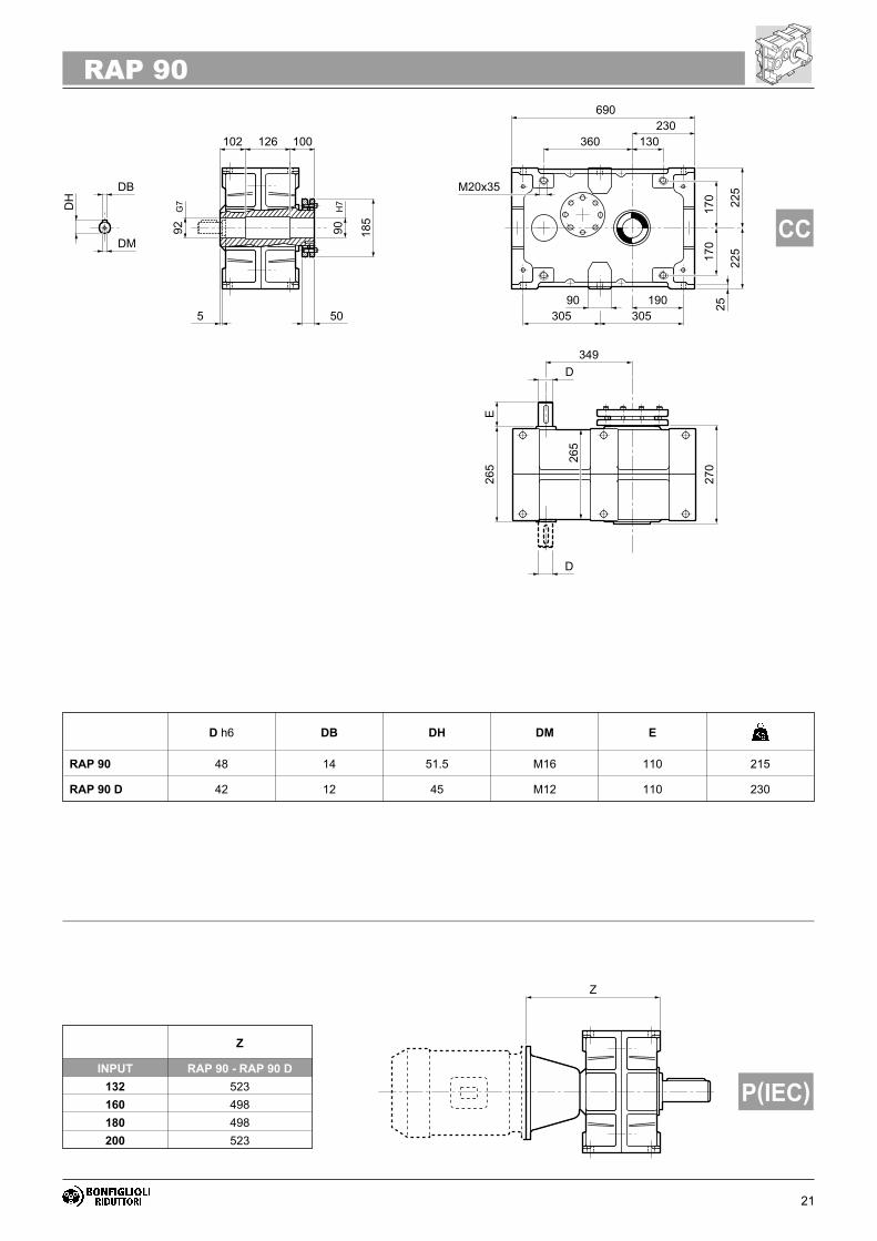
RAP 90
��
��� ��
�� ���
��
����
� ������
��
��
�
�
���
��
��
�
�
��
�
����
��
�
��
�
��
�����
�
��
��
��
�� ���
��
����
� ������
��
��
�
�
��
����
����
����
��
�
��
�
�
�
�
�
21
RAP 90
����
�
��
�� ���
��
����
� ������
��
��
�
�
���
��
��
� �
� �
��
��
�
��
�
���
����
��
�
��
�
�
Z
INPUT RAP 90 - RAP 90 D
132 523
160 498
180 498
200 523
D h6 DB DH DM E
RAP 90 48 14 51.5 M16 110 215
RAP 90 D 42 12 45 M12 110 230

22
RAP 100
��
��� ����
�� ���
�
����
� ����
��
�
��
��
��
�
��
��
�
����
��
�
��
��
�
�����
�
��
��
��
�� ���
�
����
� ����
��
�
�
����
���
�
����
��
�
��
��
�
�
�
�

23
RAP 100
� ��
� ��
��
���
��
����
�
��
�� ���
�
����
� ����
��
�
��
��
��
����
��
�
��
��
�
��
��
����
�
Z
INPUT RAP 100 - RAP 100 D
132 586
160 586
180 586
200 586
225 561
D h6 DB DH DM E
RAP 100 48 14 51.5 M16 110 315
RAP 100 D 42 12 45 M12 110 335

24
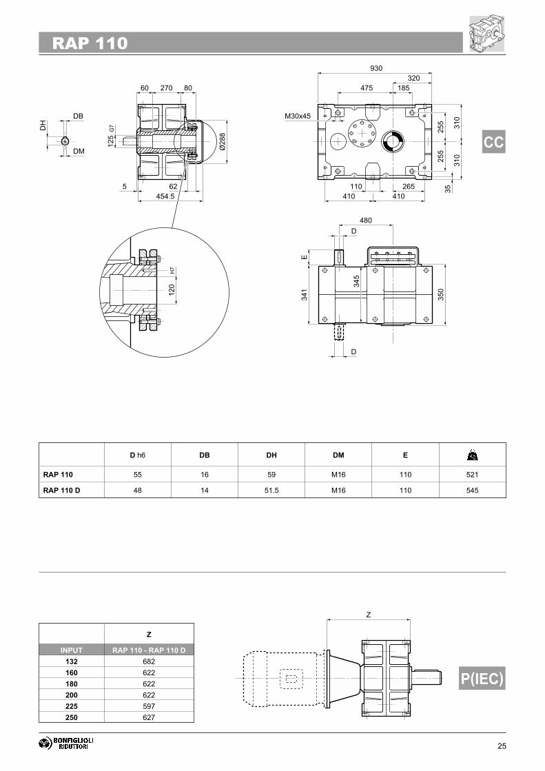
RAP 110
���
��� ����
��� ����
��
�����
�� ������
��
��
����
��
��
��
��
�
��
���
�
���
���
�
���
��
�
������
�
��
��
��
��� ����
��
�����
�� ������
��
��
����
��
�
�����
����
�
���
���
�
���
��
�
�
�
�
25
RAP 110
����
�
��
��� ����
��
�����
�� ������
��
��
����
��
��
��
��
���
���
�
���
��
�
� �
� �
�
��
��
�����
�
�
�
��
Z
INPUT RAP 110 - RAP 110 D
132 682
160 622
180 622
200 622
225 597
250 627
D h6 DB DH DM E
RAP 110 55 16 59 M16 110 521
RAP 110 D 48 14 51.5 M16 110 545
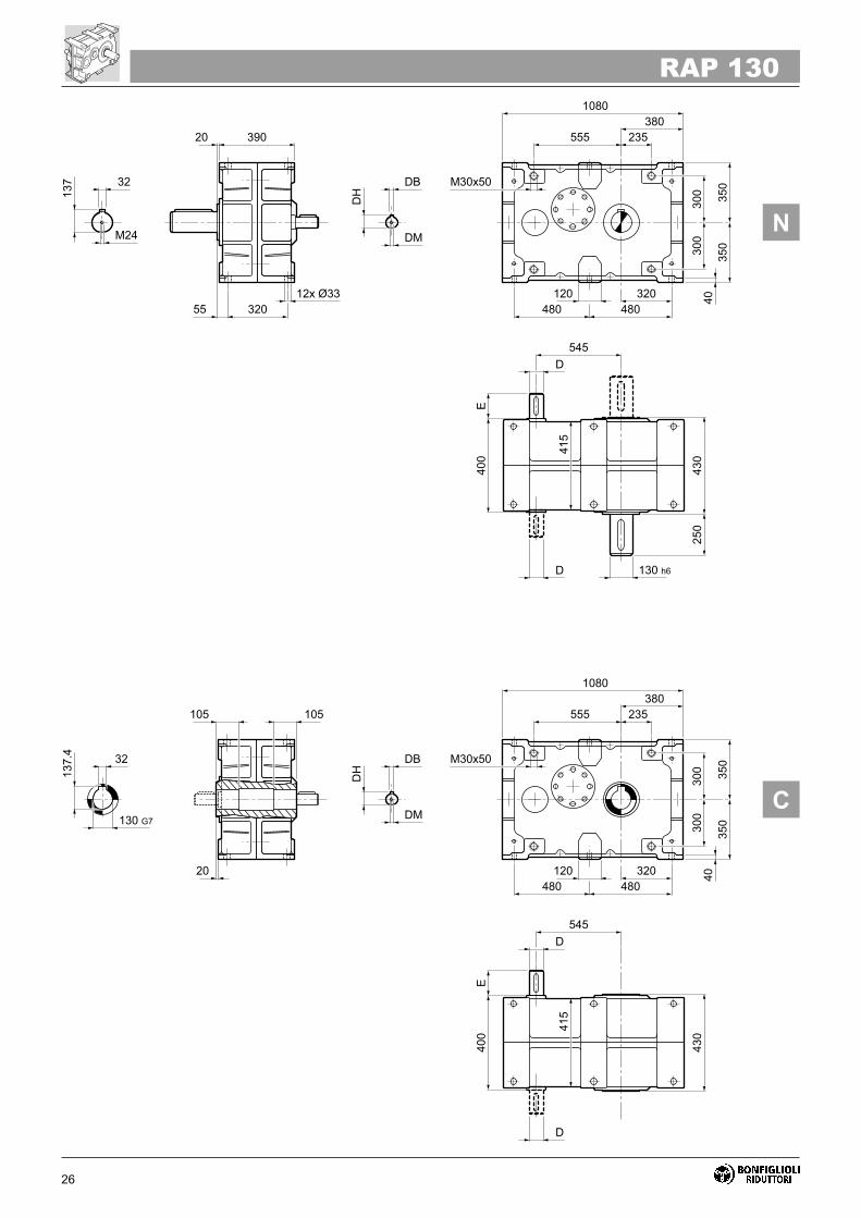
26
RAP 130
��
��� �����
��� ����
��
����
� �����
�
�
���
��
��
��
��
�
��
���
�
����
��
���
��
�
������
�
��
��
��
��� ����
��
����
� �����
�
�
���
��
�
�����
����
�
����
��
���
��
�
��
��

27
RAP 130
����
�
��
��� ����
��
����
� �����
�
�
���
��
��
��
��
����
��
���
��
�
� �
� ��
��
���
��
���
��
��
��
D h6 DB DH DM E
RAP 130 60 18 64 M16 140 800
RAP 130 D 55 16 59 M16 110 855
Z
INPUT RAP 130 - RAP 130 D
160 708
180 708
200 708
225 683
250 713
280 713
28
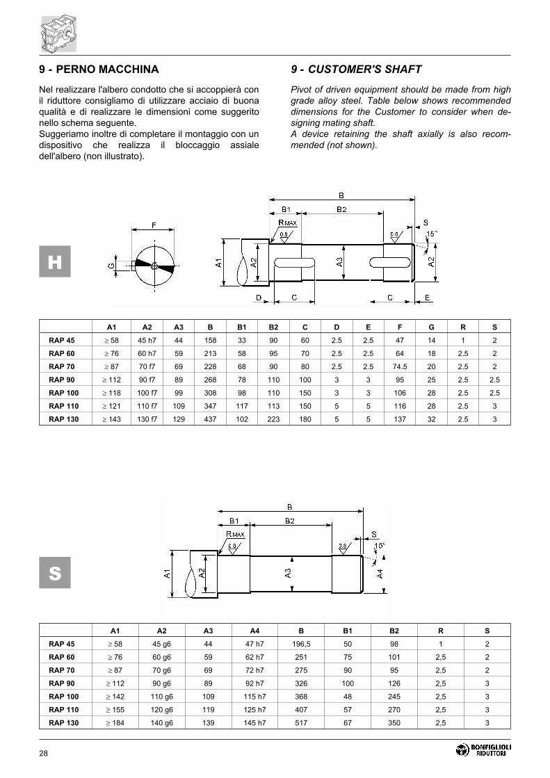
Nel realizzare l'albero condotto che si accoppierà con
il riduttore consigliamo di utilizzare acciaio di buona
qualità e di realizzare le dimensioni come suggerito
nello schema seguente.
Suggeriamo inoltre di completare il montaggio con un
dispositivo che realizza il bloccaggio assiale
dell'albero (non illustrato).
Pivot of driven equipment should be made from high
grade alloy steel. Table below shows recommended
dimensions for the Customer to consider when de-
signing mating shaft.
A device retaining the shaft axially is also recom-
mended (not shown).
9 - PERNO MACCHINA 9 - CUSTOMER'S SHAFT
S
H
A1 A2 A3 B B1 B2 C D E F G R S
RAP 45 � 58 45 h7 44 158 33 90 60 2.5 2.5 47 14 1 2
RAP 60 � 76 60 h7 59 213 58 95 70 2.5 2.5 64 18 2.5 2
RAP 70 � 87 70 f7 69 228 68 90 80 2.5 2.5 74.5 20 2.5 2
RAP 90 � 112 90 f7 89 268 78 110 100 3 3 95 25 2.5 2.5
RAP 100 � 118 100 f7 99 308 98 110 150 3 3 106 28 2.5 2.5
RAP 110 � 121 110 f7 109 347 117 113 150 5 5 116 28 2.5 3
RAP 130 � 143 130 f7 129 437 102 223 180 5 5 137 32 2.5 3
A1 A2 A3 A4 B B1 B2 R S
RAP 45 � 58 45 g6 44 47 h7 196,5 50 98 1 2
RAP 60 � 76 60 g6 59 62 h7 251 75 101 2,5 2
RAP 70 � 87 70 g6 69 72 h7 275 90 95 2,5 2
RAP 90 � 112 90 g6 89 92 h7 326 100 126 2,5 3
RAP 100 � 142 110 g6 109 115 h7 368 48 245 2,5 3
RAP 110 � 155 120 g6 119 125 h7 407 57 270 2,5 3
RAP 130 � 184 140 g6 139 145 h7 517 67 350 2,5 3

29
Schema di assemblaggio
1) Svitare le viti di bloccaggio gradualmente e in suc-
cessione rimuovendo il calettatore.
2) Pulire e sgrassare bene le zone di accoppiamento
fra albero lento riduttore e albero condotto della
macchina. Non oliare od usare solventi.
3) Effettuare l’accoppiamento fra albero condotto e il
riduttore.
4) Applicare il calettatore sull’albero cavo del riduttore.
5) Avvitare a fondo tutte le viti del calettatore gra-
dualmente e in successione. È necessario effet-
tuare alcune passate affinché tutte le viti siano
avvitate completamente alla coppia di serraggio
indicata.
N.B. - I particolari illustrati nelle sequenze di montag-
gio e smontaggio del calettatore non sono oggetto
della fornitura.
Assembly procedure
1) Remove the locking bolts, then the shrink disc.
2) Clean both the surface of the driven shaft and the
inner surface of the hollow shaft thoroughly. Do
not use solvents nor lubricants on the mating sur-
faces.
3) Fit the gearbox onto the machine solid shaft.
4) Slide the shrink disc over the protrusion of the
gearbox hollow shaft.
5) Tighten all bolts gradually and in a circular se-
quence using a torque wrench. Several steps may
be required before the tightening torque specified
for the gear unit is achieved.
N.B. - Parts for the assembly and disassembly of the
gearboxes are out of the scope for supply.
��� !�"�#$ $�%"&'()!&$������������� ������
��� !�"�#$ $�%"&'()!&$������������� ������
SMONTAGGIOREMOVAL
MONTAGGIOASSEMBLING
*! (&+�+��,&$��$&+������������� ���
��
��
�-��
�� ��
�
EH EL EM ENVitiBolts
Mt[Nm]
RAP 45RAP 45 D
— — 100 30.5 M6x25 15
RAP 60RAP 60 D
— — 145 32.5 M8x30 40
RAP 70RAP 70 D
— — 155 39 M8x35 40
RAP 90RAP 90 D
— — 185 50 M10x40 83
RAP 100RAP 100 D
126 M8x20 230 58 M12x45 130
RAP 110RAP 110 D
137 M8x20 265 62 M12x50 130
RAP 130RAP 130 D
162 M10x25 330 85 M16x65 325
10 - INSTALLAZIONE RIDUTTORECON CALETTATORE
10 - INSTALLATION OF THE SHRINK DISC

30
R = Carico radiale (N)
M = Momento torcente sull’albero in esame (Nm)
D = Diametro primitivo (mm) dell'organo di trasmis-
sione calettato sull'albero.
K = 1.0 - Trasmissione a catena
1.25 - Trasmissione a ingranaggio
1.5-2.0 - Trasmissione a cinghia trapezoidale
Il valore della forza risultante R così ricavata dovrà
essere inferiore al valore ammissibile Rn fornito dal
catalogo per il dato riduttore.
• I valori dei carichi radiali ammissibili forniti dal cata-logo sono riferiti all'applicazione di forze in corri-
spondenza della mezzeria dell'albero. In caso di
forze applicate più esternamente consultare il Ser-
vizio Tecnico del costruttore.
• Il valore del carico assiale ammissibile è pari al
20% del corrispondente carico radiale.
• I carichi nominali per velocità diverse da quelle elenca-te a catalogo si possono ottenere per interpolazione.
• È consigliabile montare la puleggia, la ruota denta-ta o l’ingranaggio il più vicino possibile alla battuta
dell’albero.
• Nel caso di alberi bisporgenti il valore del carico
sopportabile da ciascuna estremità è uguale ai 2/3
del valore di tabella, purchè i due carichi siano di
uguale intensità e agiscano nello stesso verso.
11 - CALCOLO DEL CARICO RADIALE 11 - CALCULATION OF RADIAL LOAD
R2 M K
D�
� �000
R = Radial load (N)
M = Torque (Nm)
D = PCD (mm) of the transmission element.
K = 1 - Chain transmission
1.25 - Gear transmission
1.5-2.0 - V-belt transmission
The resulting force R, so calculated, must be lower in
value than the admissible overhung load Rn listed in
the catalogue for the specific gear unit.
• Admissible overhung loads listed in the catalogueapply in the case of forces acting at midpoint of the
shaft under study. Should the application point be
shifted further out consult BONFIGLIOLI Technical
Service.
• Admissible thrust load equals 20% of the corre-
spondent overhung load listed in the catalogue.
• Nominal ratings for drive speeds not listed in thecatalogue may be obtained by interpolation.
• To optimize bearing lifetime, mounting of the trans-mission element as close as possible to shaft
shoulder is largely preferred.
• In the case of double-extended shafts, the loadingwhich may be taken by each of the shaft ends is
equal to 2/3rds of the rated OHL, if the two forces
are equal and operate in the same direction.
31
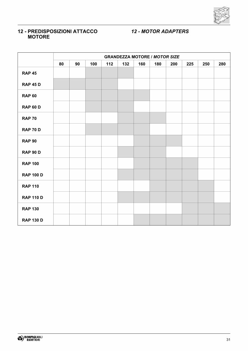
12 - PREDISPOSIZIONI ATTACCOMOTORE
12 - MOTOR ADAPTERS
GRANDEZZA MOTORE / MOTOR SIZE
80 90 100 112 132 160 180 200 225 250 280
RAP 45
RAP 45 D
RAP 60
RAP 60 D
RAP 70
RAP 70 D
RAP 90
RAP 90 D
RAP 100
RAP 100 D
RAP 110
RAP 110 D
RAP 130
RAP 130 D

32
INDICE DELLE REVISIONI (R) INDEX OF REVISIONS (R)
Questa pubblicazione annulla e sostituisce ogni precedenteedizione o revisione. Ci riserviamo il diritto di apportare modifi-che senza preavviso. È vietata la produzione anche parzialesenza autorizzazione.
This publication supersedes and replaces any previous editionand revision. We reserve the right to implement modificationswithout notice. This catalogue cannot be reproduced, even par-tially, without prior consent.
R1
Descrizione Description
Related Documents


