3D Methods in Computer Vision Richter Miloslav, Department of Control and Instrumentation Faculty of Electrical Engineering and Communication Brno University of Technology

Welcome message from author
This document is posted to help you gain knowledge. Please leave a comment to let me know what you think about it! Share it to your friends and learn new things together.
Transcript

3D Methods in Computer Vision
Richter Miloslav, Department of Control and Instrumentation Faculty of Electrical Engineering and Communication Brno University of Technology

3D Measurement characteristics Pros: - noncontact measurement of: position, distance, shape, surface - space coordinates measurement - 3D shape detection – “reverse engineering” – real object model creation, for construction, for virtual
reality - speed measurement (with time information) Cons: - big amount of data for obtaining, transfer, processing and archiving - complex and sequential data processing - difficult 3D data representation and visualisation -
3D model of hat and face

Another options for 3D measurement Laser measurement - Time Of Flight (TOF) – one or more rays - pro: great distance and sufficient accuracy - con: long time for (multiple) measurement - interference measurement (phase shift) radar - time of flight - speed measurement by doppler effect (changing distance in time) (ultra)sound - position or surface measurement (by field of detectors) - precise measurement for less amount of measured objects)

HW for 3D image processing applications Some producers of image processing devices (industrial cameras and accessories) Basler, PointGrey (now FLIR), DALSA, Matrox, Pleora, Sony, The Imaging Source, Stemmer Imaging, Allied Vision Technologies, National Instruments.

SW libraries for image processing with 3D algorithms (applications or source code): - SDK of camera producers – special for producer HW, sometimes not exactly what you need - HALCON ( http://www.halcon.com/ ) - Matrox Imaging Library (http://www.matrox.com/imaging/en/products/software/mil/ ) - MATLAB (http://www.mathworks.com/products/image/ ) - OpenCV ( http://opencv.org/ ) – free (BSD licence) source code for C/C++ (Python, Java…), originally
produced by Intel (names used are TM)

HW standards - GigE Vision, USB 3.0 Vision, CoaXpress, CameraLink – "HW" standards - EMVA 1288 – descriptions and definitions of camera (or detector) parameters, its definitions and
measurement specification – for camera comparing - GenICam – try to unify and create reusable applications (3rt party), driver parameters, data stream
optimization - GenICam (Generic Interface for cameras). Three parts: API definitions – xml files for configuration,
setup, and camera control. TL – definitions of buffers and data transfer – e.g. position and form of RGB in transfer signal. Name conventions – definition of data types, methods and their names (RoThetaPhi16, LineScan, Cartesian …).
- definitions for resulting representation of 3D data – points, surfaces. Cartesian, spherical coordinates, depth maps and textures, data validity …
http://www.visiononline.org/ association for vision information – association of companies for component, camera and vision standards

WOWvx 2D-plusDepth formát / WOWvx Declipse 3D format (Phillips &...)

3D methods in computer vision - Interference methods – sensitive and accurate methods,
measurement of continuous surfaces, small depth range. With a measurement grid or interference of light waves.. Interference image – from maximum to maximum it is height of one wavelength (shift of one line pair between measuring and reference grids).
- 3D from sharpness – used for small distances, set of pictures with precise knowledge of the detector shift is taken. For measured detail the sharpest image determinates the depth of the detail.
- 3D shape from shadow – the object pictures are taken with different lightning directions. Depending on the brightness ratios, normal vectors are determined at given locations.
- triangulation
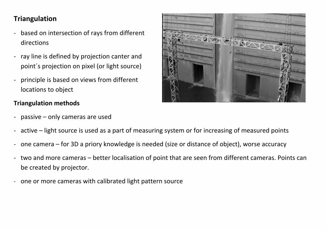
Triangulation - based on intersection of rays from different
directions - ray line is defined by projection canter and
point´s projection on pixel (or light source) - principle is based on views from different
locations to object Triangulation methods - passive – only cameras are used - active – light source is used as a part of measuring system or for increasing of measured points - one camera – for 3D a priory knowledge is needed (size or distance of object), worse accuracy - two and more cameras – better localisation of point that are seen from different cameras. Points can
be created by projector. - one or more cameras with calibrated light pattern source
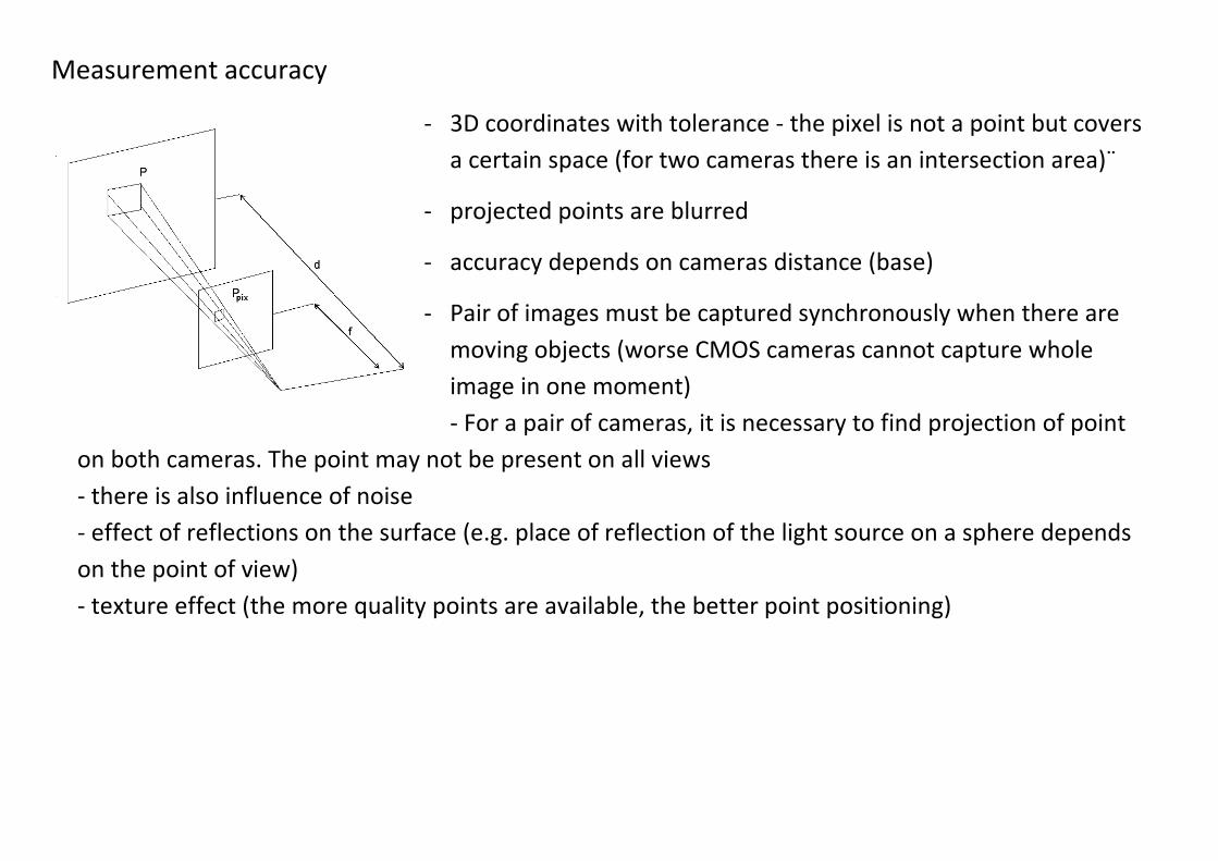
Measurement accuracy - 3D coordinates with tolerance - the pixel is not a point but covers
a certain space (for two cameras there is an intersection area)¨ - projected points are blurred - accuracy depends on cameras distance (base) - Pair of images must be captured synchronously when there are
moving objects (worse CMOS cameras cannot capture whole image in one moment) - For a pair of cameras, it is necessary to find projection of point
on both cameras. The point may not be present on all views - there is also influence of noise - effect of reflections on the surface (e.g. place of reflection of the light source on a sphere depends on the point of view) - texture effect (the more quality points are available, the better point positioning)
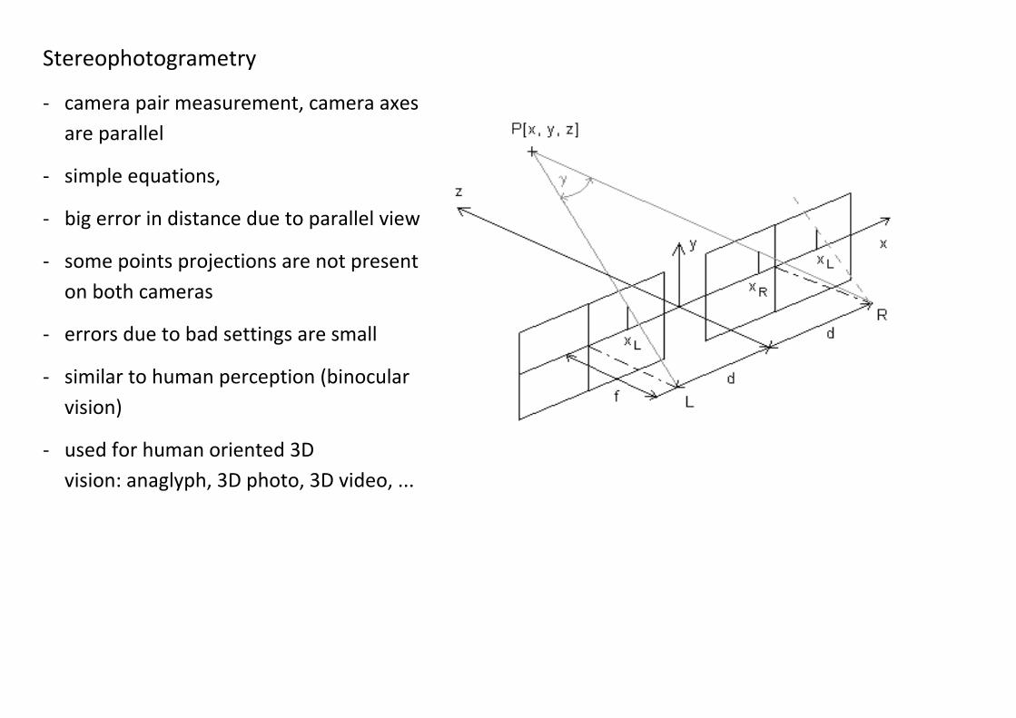
Stereophotogrametry - camera pair measurement, camera axes
are parallel - simple equations, - big error in distance due to parallel view - some points projections are not present
on both cameras - errors due to bad settings are small - similar to human perception (binocular
vision) - used for human oriented 3D
vision: anaglyph, 3D photo, 3D video, ...

Stereophotogrametry equations for parallel camera axes x
z
x‘x” x‘x”
f f
0 bx
p=x’-x”
paralax – change of point position on cameras
p
bxx x' p
byy x' p
bfz x
equations for point coordinates (camera coordinates in mm)
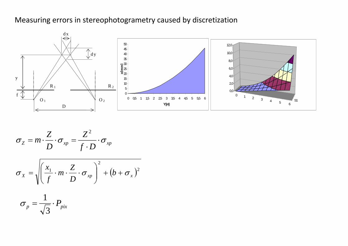
Measuring errors in stereophotogrametry caused by discretization
R 1 R 2
O2 O1 f
y
dy
dx
D
0
5
10
15
20
25
30
35
40
45
50
0 0,5 1 1,5 2 2,5 3 3,5 4 4,5 5 5,5 6
Y [m]
o[m
m]
0 1 2 3 4 5 6S1
0,0
2,0
4,0
6,0
8,0
10,0
12,0
xpxpZ Df
Z
D
Zm
2
2
2
1xxpX b
D
Zm
f
x
pixp P3
1

Stereophotogrametry measurement of plane with camera pair
Top row – x,y,z coordinates for pixels on detector. Bottom row – respective error for top row. Two cameras, camera view angle 90°, view to camera axes intersection,
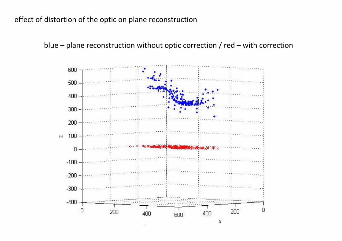
effect of distortion of the optic on plane reconstruction
blue – plane reconstruction without optic correction / red – with correction

Determination of distortion correction coefficients - based on calibration pattern – 3D is better - resulting value consists from basic value and corrections - it is possible to determine the coefficients during
computation of 3D coordinates
Z
Y
Z
Xcyx ,, central projection
...45
23 rcarcadc
c
dc
r
dr radial distortion
...45
23 rca
Z
Xrca
Z
Xdx … correction of radial distoriton for x dimension
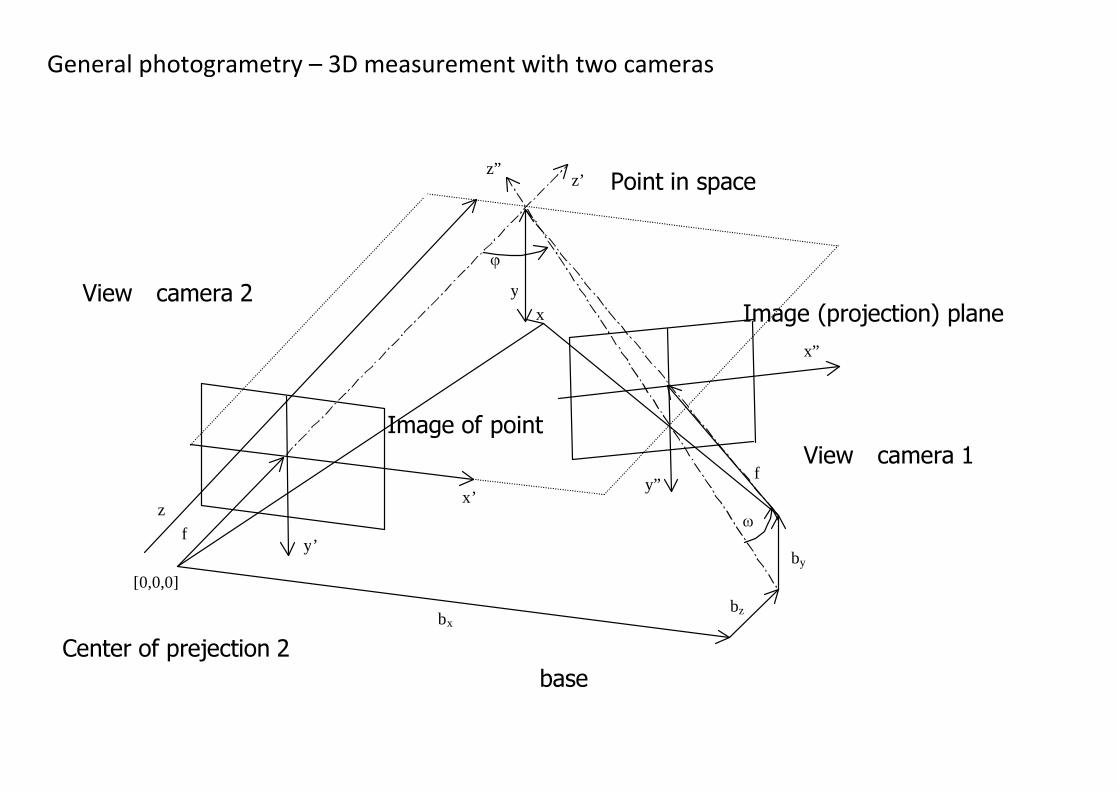
General photogrametry – 3D measurement with two cameras
x”
y”x’
y’
z”z’
bxbz
z
f
y
x
by
[0,0,0]
f
Point in space
View - camera 1
View - camera 2
baseCenter of prejection 2
Image (projection) plane
Image of point
parts of general photogrametry configuration - scene – covered area – coupled with world coordinates - image – resulting 2D projection from given camera with optics - view – space coordinates for taken images. Described by coordinates transformation - camera – charakterization of scene projection to detector. Inner orientation (center of image,
camera constatn). - scene objects (defined by their properties – luminance, color, dimensions …) - more coupled cameras (stereo pair), objects (rigid body) can help to calculations - motion (additional informations) - more views lead to better accuracy – especially when seen from different directions - no problem when the point is missing on some image (two are enough) -

Mathematical apparatus of general photogrametry - coplanarity condition Q = Σ (b x v1) . v2
b – base; v1 and v2 vector directions from projection center to point from both cameras; Q – criterion function, result is volume of object (edges are vectors and base) (smaller value is better)
relationship between coordinate systems
transformation equation
o
o
o
Z
Y
X
Z
Y
X
R
z
y
x
*
criterion function components 0
232221
333231
0232221
131211
)()()(
)()()(
)()()(
)()()(
vZZrYYrXXr
ZZrYYrXXrfv
uZZrYYrXXr
ZZrYYrXXrfu
uuu
uuu
uuu
uuu

- For coordinate calculation 5 points is enough - more than 8 points is recomended - rotations are independent on scale. Less points is needed for
rotations calculation (relative orientation) - outer (absolut) orientation – 6 degrees of freedom (3 rotation
angles and 3 translations). Points for ratations and distance for scale is enough.
- methods for solving the problem is called „bundle adjustment“ and it uses minimizing of the criterion function
- every projected point gives two equations (for x and y) - alternative: Rodrigues angles (defined by direction vector)
1000
0coscoscossinsinsincossinsincossincos
0cossincoscossinsinsinsincoscossinsin
0sinsincoscoscos
R

Epipolar lines - if the relation between two views is known, it is possible to extend projection point to space -> line.
Projection of the line on the second image is called epipolar line (generally a curve). The second projection of the point should lie near the line.
- image edges/lines in base direction have worse information. There is not possibility locate them in the direction (3D detection of the edges is better with three cameras) (Note.: the third lens on the picture is probably only finder)

Rectification - displaying in 3D is often now - 3D imaging is SIRDS (from depth map) or anaglyph - 3D is also present in 3D TV (active or passive principle) - for these types of imagery, the images must be planar. Otherwise, the
nervous system exerts strain on processing „shifted“ data - for image correction the rectification is use – images are recalculated in
such way, that lei in the same plane. The resulting images looks like taken by the same and ideal stereo cameras with parallel axes
- rectification equations for left and right image (P Point, M real and required/new projection parameters (camera), R transformation for rectification and for left and right view
llrectnewrectl PMRMP 1
,
rrrectnewrectr PMRRMP 1
,
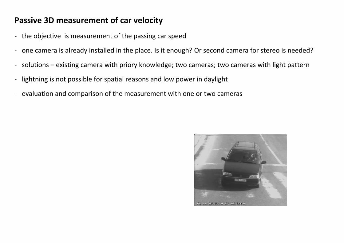
Passive 3D measurement of car velocity - the objective is measurement of the passing car speed - one camera is already installed in the place. Is it enough? Or second camera for stereo is needed? - solutions – existing camera with priory knowledge; two cameras; two cameras with light pattern - lightning is not possible for spatial reasons and low power in daylight - evaluation and comparison of the measurement with one or two cameras
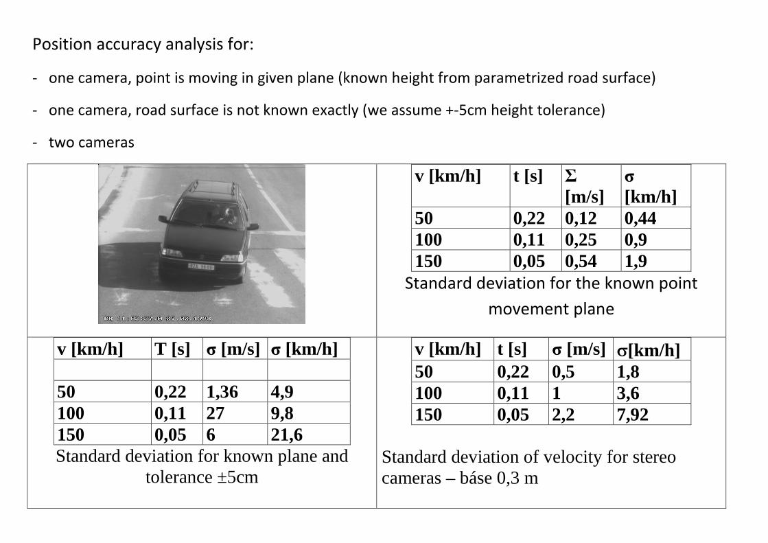
Position accuracy analysis for: - one camera, point is moving in given plane (known height from parametrized road surface) - one camera, road surface is not known exactly (we assume +-5cm height tolerance) - two cameras
v [km/h] t [s] Σ [m/s]
σ [km/h]
50 0,22 0,12 0,44 100 0,11 0,25 0,9 150 0,05 0,54 1,9
Standard deviation for the known point movement plane
v [km/h] T [s] σ [m/s] σ [km/h] 50 0,22 1,36 4,9 100 0,11 27 9,8 150 0,05 6 21,6 Standard deviation for known plane and
tolerance ±5cm
v [km/h] t [s] σ [m/s] [km/h] 50 0,22 0,5 1,8 100 0,11 1 3,6 150 0,05 2,2 7,92
Standard deviation of velocity for stereo cameras – báse 0,3 m

Determination of vehicle speed - To determine the position of passing vehicle, a single camera method and a ground plane in the scene were choose - Several distances on the road were measured for identification - Images of road from different directions were taken - With the help of the calibration pattern, the camera's internal orientation parameters were determined - the spatial coordinates of the points on the road surface were calculated from the pictures and known positions/distances - the location of measuring camera and the parameters of its internal orientation were determined from the measured points on the road surface - the measuring plane has been parameterized at a given distance above the ground plane - the transformation from the plane of the chip (the projection of the point of the measured object moving in a given plane) to ground plane (where real points move) is calculated on the plane - after determining the position of the measured point on the chip, a transformation was used that transformed it into the road system (real coordinates on measuring plane)

Principle of selected single camera method - The method can not be used if we do not know (the surface) where the object moves - as the "surface" of movement, we choose plane in the height from the road where the bumper of the passenger car moves - if the resulting area can be declared as a plane, the result is the transformation from the plane (chip) to the plane (of movement) of the body - the selected (movement) plane must be measured and parameterized for the following calculations. It is necessary to know its mutual position with the camera. - the resulting position of the moving object (cars) is obtained as the intersection of the beam passing through projection centre, the corresponding / measured pixel and the given plane - Measurement plane determination procedure: determine the ground plane equation relative to the camera and lift this plane to the desired height in which measuring will be implemented.

HW for 3D computer vision - stereo camera bumblebee – Point grey (https://eu.ptgrey.com/stereo-vision-cameras-systems,
https://eu.ptgrey.com/triclops )

HW for 3D computer vision - set of distance detector and 3D scanner – (http://www.creaform3d.com/en/metrology-
solutions/optical-3d-scanner-metrascan , http://www.creaform3d.com/en/metrology-solutions/portable-3d-scanners , https://www.ndigital.com/products/ )
distances 0.2 – 10m; accuracy 0.03mm
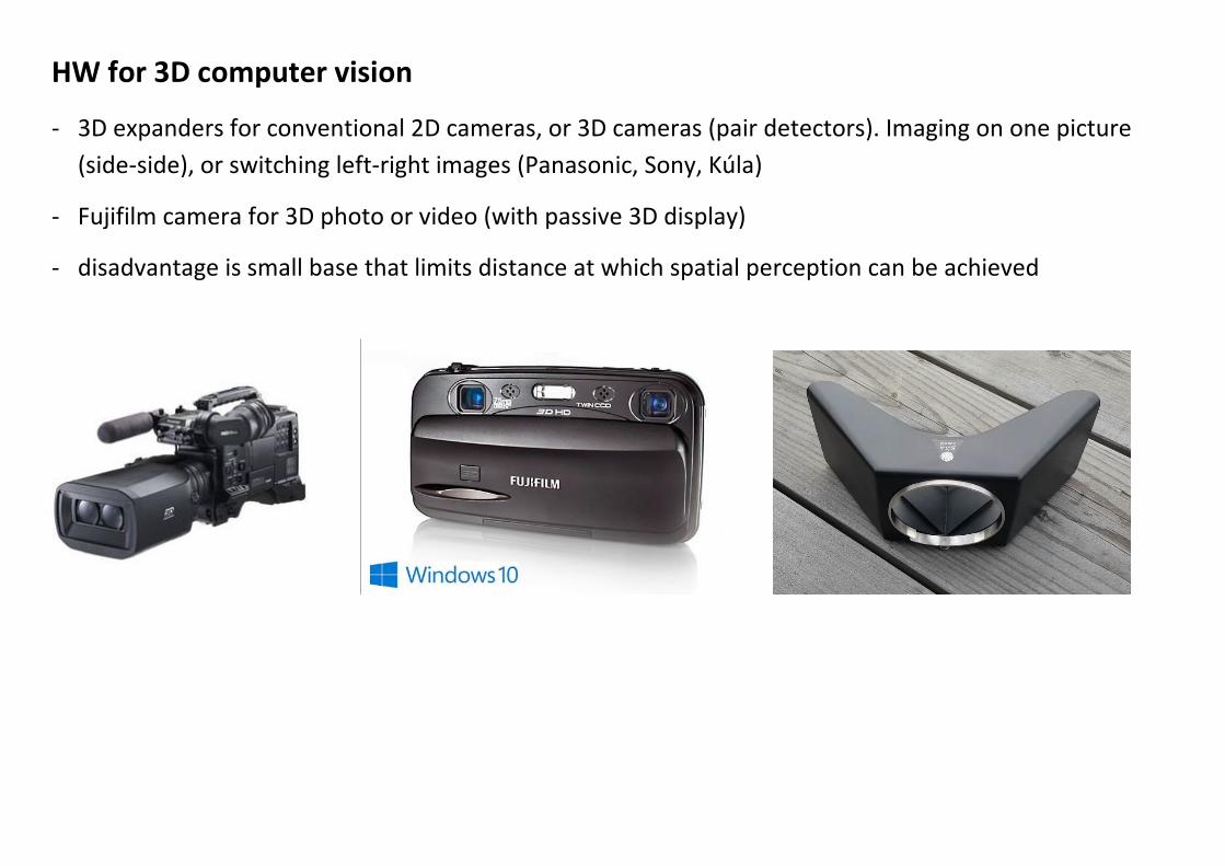
HW for 3D computer vision - 3D expanders for conventional 2D cameras, or 3D cameras (pair detectors). Imaging on one picture
(side-side), or switching left-right images (Panasonic, Sony, Kúla) - Fujifilm camera for 3D photo or video (with passive 3D display) - disadvantage is small base that limits distance at which spatial perception can be achieved
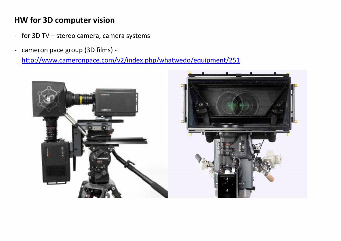
HW for 3D computer vision - for 3D TV – stereo camera, camera systems - cameron pace group (3D films) -
http://www.cameronpace.com/v2/index.php/whatwedo/equipment/251
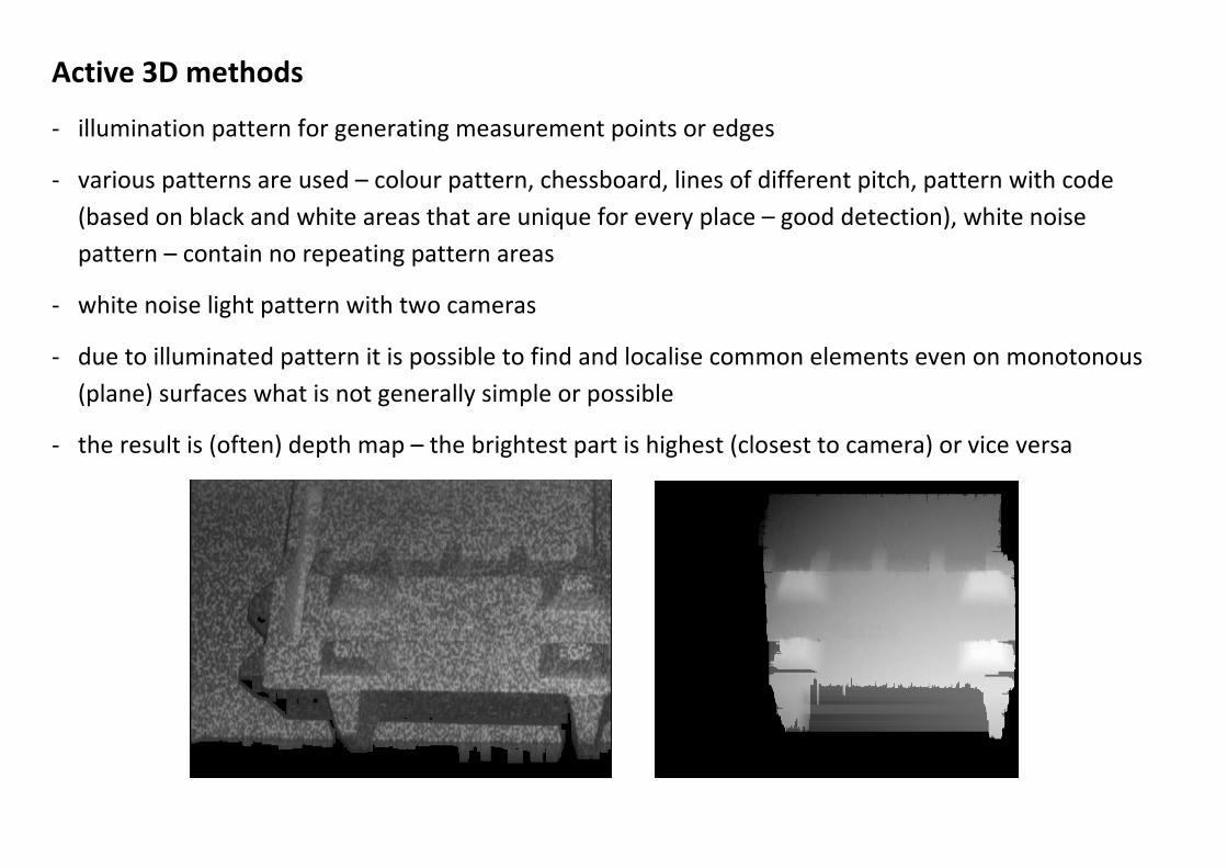
Active 3D methods - illumination pattern for generating measurement points or edges - various patterns are used – colour pattern, chessboard, lines of different pitch, pattern with code
(based on black and white areas that are unique for every place – good detection), white noise pattern – contain no repeating pattern areas
- white noise light pattern with two cameras - due to illuminated pattern it is possible to find and localise common elements even on monotonous
(plane) surfaces what is not generally simple or possible - the result is (often) depth map – the brightest part is highest (closest to camera) or vice versa
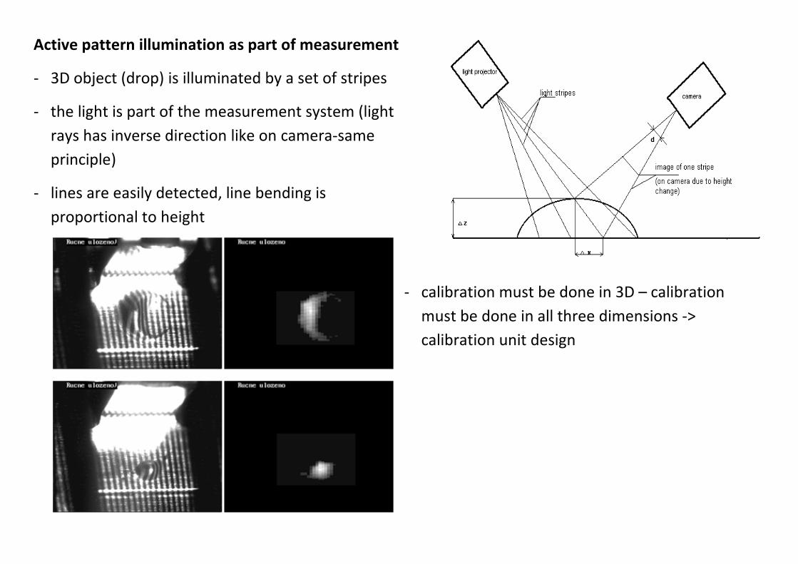
Active pattern illumination as part of measurement - 3D object (drop) is illuminated by a set of stripes - the light is part of the measurement system (light
rays has inverse direction like on camera-same principle)
- lines are easily detected, line bending is proportional to height
- calibration must be done in 3D – calibration must be done in all three dimensions -> calibration unit design
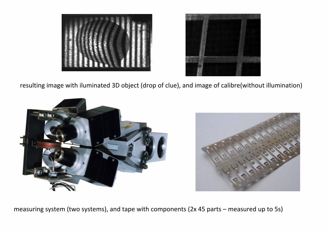
resulting image with iluminated 3D object (drop of clue), and image of calibre(without illumination)
measuring system (two systems), and tape with components (2x 45 parts – measured up to 5s)

Active light measurement with laser plane - laser illumination gives good contrast ratio for detection. Filters can remove background illumination
and strengthen contrast. - the method is slower (there is only one light plane cut in one image) - light source must be calibrated with camera (for example: camera to camera transformation) - known movement (camera or object) is part of calculations - laser beam generators has different quality (beam width)
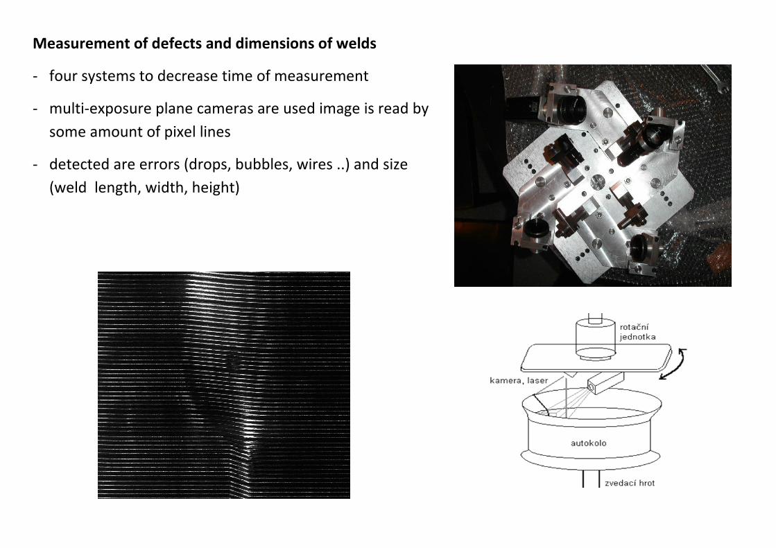
Measurement of defects and dimensions of welds - four systems to decrease time of measurement - multi-exposure plane cameras are used image is read by
some amount of pixel lines - detected are errors (drops, bubbles, wires ..) and size
(weld length, width, height)
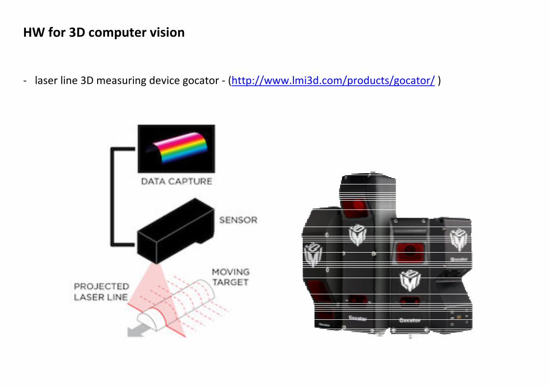
HW for 3D computer vision - laser line 3D measuring device gocator - (http://www.lmi3d.com/products/gocator/ )
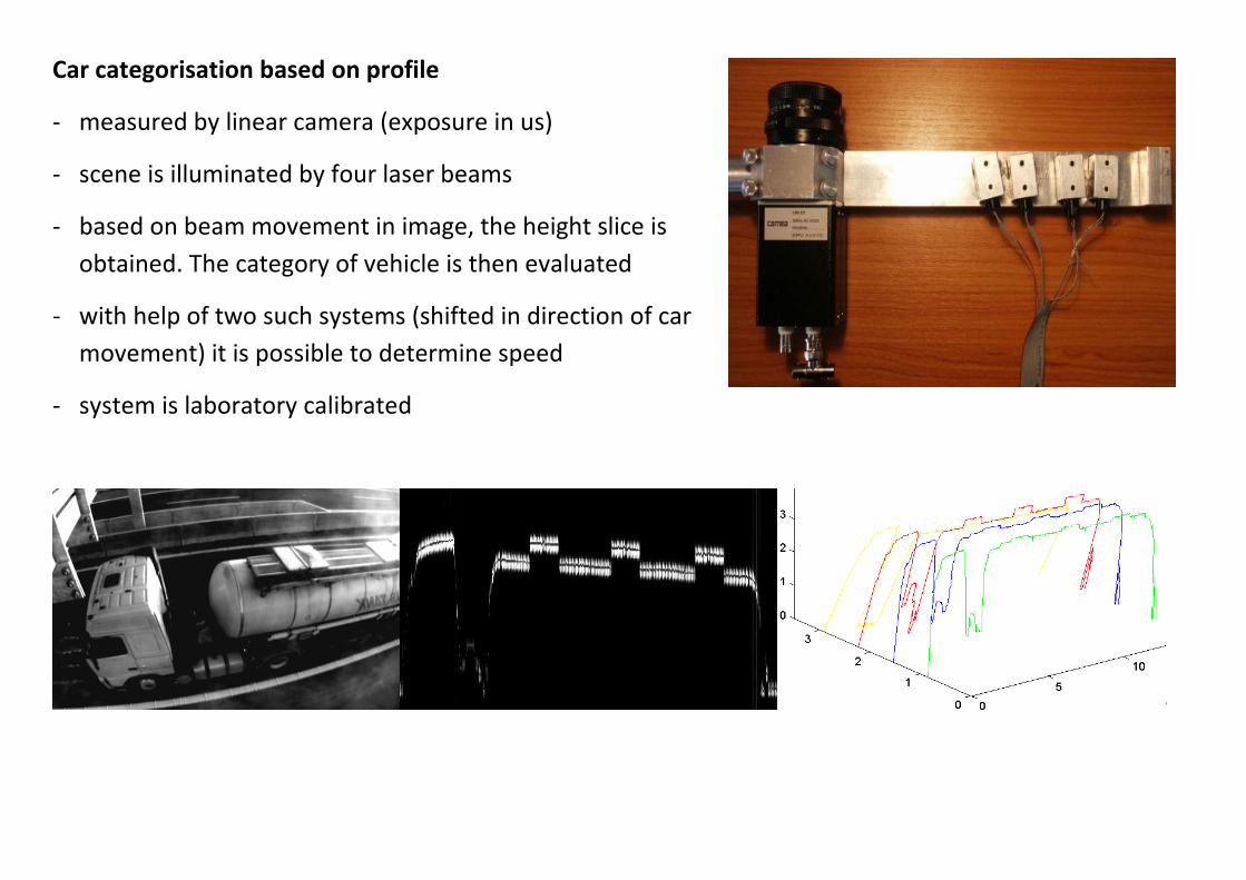
Car categorisation based on profile - measured by linear camera (exposure in us) - scene is illuminated by four laser beams - based on beam movement in image, the height slice is
obtained. The category of vehicle is then evaluated - with help of two such systems (shifted in direction of car
movement) it is possible to determine speed - system is laboratory calibrated
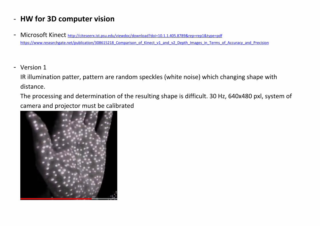
- HW for 3D computer vision - Microsoft Kinect http://citeseerx.ist.psu.edu/viewdoc/download?doi=10.1.1.405.8789&rep=rep1&type=pdf
https://www.researchgate.net/publication/308615218_Comparison_of_Kinect_v1_and_v2_Depth_Images_in_Terms_of_Accuracy_and_Precision
- Version 1 IR illumination patter, pattern are random speckles (white noise) which changing shape with distance. The processing and determination of the resulting shape is difficult. 30 Hz, 640x480 pxl, system of camera and projector must be calibrated

- Version 2 TOF (Time Of Flight), luminance and distance (depth) information are obtained together. Fast distance detection, smaller accuracy (precise timing is required, signal edges are distorted), 30Hz, 512 x 424pxl
HW for 3D computer vision - pmd 3D sensor – TOF - ifm (https://www.ifm.com/gb/en/shared/technologies/3d-smart-sensor-
o3m/applikationen/abstandskontrolle )
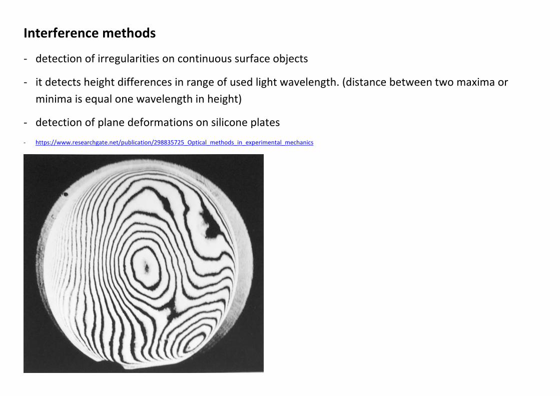
Interference methods - detection of irregularities on continuous surface objects - it detects height differences in range of used light wavelength. (distance between two maxima or
minima is equal one wavelength in height) - detection of plane deformations on silicone plates - https://www.researchgate.net/publication/298835725_Optical_methods_in_experimental_mechanics
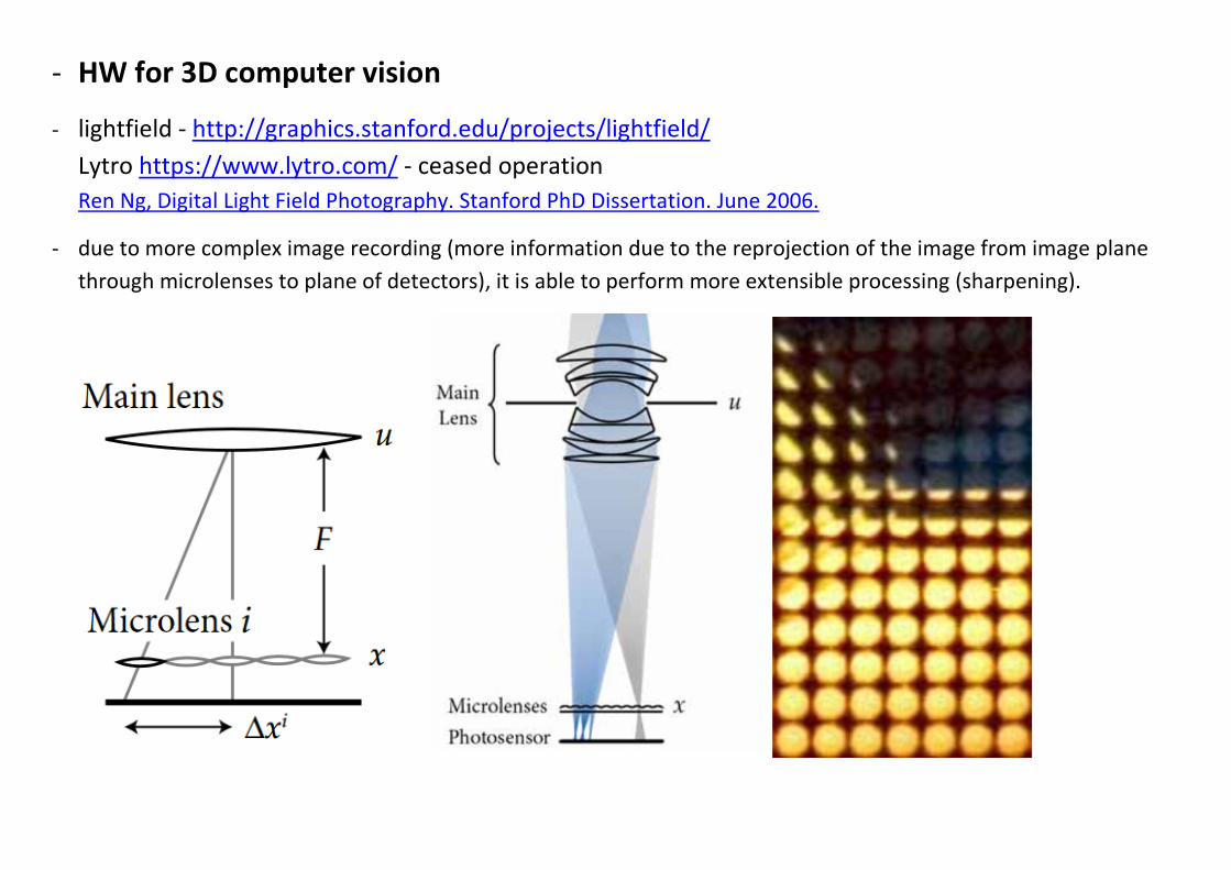
- HW for 3D computer vision - lightfield - http://graphics.stanford.edu/projects/lightfield/
Lytro https://www.lytro.com/ - ceased operation Ren Ng, Digital Light Field Photography. Stanford PhD Dissertation. June 2006.
- due to more complex image recording (more information due to the reprojection of the image from image plane through microlenses to plane of detectors), it is able to perform more extensible processing (sharpening).
Related Documents