User’s Manual All information contained in these materials, including products and product specifications, represents information on the product at the time of publication and is subject to change by Renesas Electronics Corp. without notice. Please review the latest information published by Renesas Electronics Corp. through various means, including the Renesas Electronics Corp. website (http://www.renesas.com). RI850V4 Real-Time Operating System User’s Manual: Coding Rev.1.00 Apr 2011 Target Tool RI850V4 www.renesas.com

Welcome message from author
This document is posted to help you gain knowledge. Please leave a comment to let me know what you think about it! Share it to your friends and learn new things together.
Transcript

User’s M
anual
All information contained in these materials, including products and product specifications, represents information on the product at the time of publication and is subject to change by Renesas Electronics Corp. without notice. Please review the latest information published by Renesas Electronics Corp. through various means, including the Renesas Electronics Corp. website (http://www.renesas.com).
RI850V4
Real-Time Operating System User’s Manual: Coding
Rev.1.00 Apr 2011
Target Tool
RI850V4
www.renesas.com
a5077977
テキストボックス
There are corrections on this document. For the information of corrections, click the icon on the left or refer to the page below. http://tool-support.renesas.com/eng/toolnews/131016/tn5.htm
a5077977
ノート注釈
Correction to "RI850V4 Real-time OS User's Manual: Coding" of Real-time OS RI850V4 (for V850 Family and Supported by CubeSuite+) ---------------------------------------------------------------------------- 2.1 Page 22, Section 2.6, Coding Directive File Rectify the list of section names as follows: Section Section Section Name Attribute Type ROM/RAM Description ------------------------------------------------------------------------ .kernel_const R PROGBITS ROM System information table .kernel_system RX PROGBITS ROM/RAM Kernel common module, Kernel module .kernel_data RW NOBITS RAM System base table, Task ready queue, Timer queue, Management block of each object .kernel_work RW NOBITS RAM System stack, Task stack, Data queue area, Fixed-Sized Memory Pool, Variable-Sized Memory Pool 2.2 Page 350, Note 2 under item 5) System stack size: stksz Incorrect: The memory area for system stack is secured from the ".kernel_data section". Correct: The memory area for system stack is secured from the ".kernel_work section". 2.3 Page 354, Note 2 under item 6) Task stack size: stksz, memory area name: mem_area Incorrect: If specification of mem_area is omitted, the task stack is allocated to the .kernel_data section. Correct: If specification of mem_area is omitted, the task stack is allocated to the .kernel_work section. 2.4 Page 358, Note under item 3) Data count: dtqcnt, memory area name: mem_area Incorrect: If specification of mem_area is omitted, the data queue is allocated to the .kernel_data section. Correct: If specification of mem_area is omitted, the data queue is allocated to the .kernel_work section. 2.5 Page 361, Note under item 4) Basic block size: blksz, memory area name: mem_area Incorrect: If specification of mem_area is omitted, the fixed-sized memory pool is allocated to the .kernel_data section. Correct: If specification of mem_area is omitted, the fixed-sized memory pool is allocated to the .kernel_work section. 2.6 Page 362, Note under item 3) Pool size: mplsz, memory area name: mem_area Incorrect: If specification of mem_area is omitted, the variable-sized memory pool is allocated to the .kernel_data section. Correct: If specification of mem_area is omitted, the variable-sized memory pool is allocated to the .kernel_work section. 2.7 Page 370, 18.6 Memory Capacity Estimation (1) Under the heading of subsection 18.6.1 Incorrect: 18.6.1 .kernel_const section Correct: 18.6.1 .kernel_work section (2) Overview of subsection 18.6.1 Incorrect: ...assigned to the .kernel_const section (unit: bytes). Correct: ...assigned to the .kernel_work section (unit: bytes). (3) Title of Table 18-1 Incorrect: Table 18-1 .kernel_const Section Size Calculation Method Correct: Table 18-1 .kernel_work Section Size Calculation Method 2.8 Page 371 (1) Under the heading of subsection 18.6.2 Incorrect: 18.6.2 .kernel_info section Correct: 18.6.2 .kernel_const section (2) Overview of subsection 18.6.2 Incorrect: ...assigned to the .kernel_info section (unit: bytes). Correct: ...assigned to the .kernel_const section (unit: bytes). (3) Title of Table 18-2 Incorrect: Table 18-2 .kernel_info Section Size Calculation Method Correct: Table 18-2 .kernel_const Section Size Calculation Method ---------------------------------------------------------------------------- CONTACT Renesas Electronics Corporation Back issues: http://www.renesas.com/toolnews Technical support: http://www.renesas.com/contact/ Home page: http://www.renesas.com/tools

Notice 1. All information included in this document is current as of the date this document is issued. Such information, however, is
subject to change without any prior notice. Before purchasing or using any Renesas Electronics products listed herein, please confirm the latest product information with a Renesas Electronics sales office. Also, please pay regular and careful attention to additional and different information to be disclosed by Renesas Electronics such as that disclosed through our website.
2. Renesas Electronics does not assume any liability for infringement of patents, copyrights, or other intellectual property rights of third parties by or arising from the use of Renesas Electronics products or technical information described in this document. No license, express, implied or otherwise, is granted hereby under any patents, copyrights or other intellectual property rights of Renesas Electronics or others.
3. You should not alter, modify, copy, or otherwise misappropriate any Renesas Electronics product, whether in whole or in part. 4. Descriptions of circuits, software and other related information in this document are provided only to illustrate the operation of
semiconductor products and application examples. You are fully responsible for the incorporation of these circuits, software, and information in the design of your equipment. Renesas Electronics assumes no responsibility for any losses incurred by you or third parties arising from the use of these circuits, software, or information.
5. When exporting the products or technology described in this document, you should comply with the applicable export control laws and regulations and follow the procedures required by such laws and regulations. You should not use Renesas Electronics products or the technology described in this document for any purpose relating to military applications or use by the military, including but not limited to the development of weapons of mass destruction. Renesas Electronics products and technology may not be used for or incorporated into any products or systems whose manufacture, use, or sale is prohibited under any applicable domestic or foreign laws or regulations.
6. Renesas Electronics has used reasonable care in preparing the information included in this document, but Renesas Electronics does not warrant that such information is error free. Renesas Electronics assumes no liability whatsoever for any damages incurred by you resulting from errors in or omissions from the information included herein.
7. Renesas Electronics products are classified according to the following three quality grades: “Standard”, “High Quality”, and “Specific”. The recommended applications for each Renesas Electronics product depends on the product’s quality grade, as indicated below. You must check the quality grade of each Renesas Electronics product before using it in a particular application. You may not use any Renesas Electronics product for any application categorized as “Specific” without the prior written consent of Renesas Electronics. Further, you may not use any Renesas Electronics product for any application for which it is not intended without the prior written consent of Renesas Electronics. Renesas Electronics shall not be in any way liable for any damages or losses incurred by you or third parties arising from the use of any Renesas Electronics product for an application categorized as “Specific” or for which the product is not intended where you have failed to obtain the prior written consent of Renesas Electronics. The quality grade of each Renesas Electronics product is “Standard” unless otherwise expressly specified in a Renesas Electronics data sheets or data books, etc.
“Standard”: Computers; office equipment; communications equipment; test and measurement equipment; audio and visual equipment; home electronic appliances; machine tools; personal electronic equipment; and industrial robots.
“High Quality”: Transportation equipment (automobiles, trains, ships, etc.); traffic control systems; anti-disaster systems; anti-crime systems; safety equipment; and medical equipment not specifically designed for life support.
“Specific”: Aircraft; aerospace equipment; submersible repeaters; nuclear reactor control systems; medical equipment or systems for life support (e.g. artificial life support devices or systems), surgical implantations, or healthcare intervention (e.g. excision, etc.), and any other applications or purposes that pose a direct threat to human life.
8. You should use the Renesas Electronics products described in this document within the range specified by Renesas Electronics, especially with respect to the maximum rating, operating supply voltage range, movement power voltage range, heat radiation characteristics, installation and other product characteristics. Renesas Electronics shall have no liability for malfunctions or damages arising out of the use of Renesas Electronics products beyond such specified ranges.
9. Although Renesas Electronics endeavors to improve the quality and reliability of its products, semiconductor products have specific characteristics such as the occurrence of failure at a certain rate and malfunctions under certain use conditions. Further, Renesas Electronics products are not subject to radiation resistance design. Please be sure to implement safety measures to guard them against the possibility of physical injury, and injury or damage caused by fire in the event of the failure of a Renesas Electronics product, such as safety design for hardware and software including but not limited to redundancy, fire control and malfunction prevention, appropriate treatment for aging degradation or any other appropriate measures. Because the evaluation of microcomputer software alone is very difficult, please evaluate the safety of the final products or system manufactured by you.
10. Please contact a Renesas Electronics sales office for details as to environmental matters such as the environmental compatibility of each Renesas Electronics product. Please use Renesas Electronics products in compliance with all applicable laws and regulations that regulate the inclusion or use of controlled substances, including without limitation, the EU RoHS Directive. Renesas Electronics assumes no liability for damages or losses occurring as a result of your noncompliance with applicable laws and regulations.
11. This document may not be reproduced or duplicated, in any form, in whole or in part, without prior written consent of Renesas Electronics.
12. Please contact a Renesas Electronics sales office if you have any questions regarding the information contained in this document or Renesas Electronics products, or if you have any other inquiries.
(Note 1) “Renesas Electronics” as used in this document means Renesas Electronics Corporation and also includes its majority-owned subsidiaries.
(Note 2) “Renesas Electronics product(s)” means any product developed or manufactured by or for Renesas Electronics.
How to Use This Manual
Readers This manual is intended for users who design and develop application systems using
V850 microcontroller products.
Purpose This manual is intended for users to understand the functions of real-time OS
"RI850V4" manufactured by Renesas Electronics, described the organization listed
below.
Organization This manual consists of the following major sections.
CHAPTER 1 OVERVIEW
CHAPTER 2 SYSTEM CONSTRUCTION
CHAPTER 3 TASK MANAGEMENT FUNCTIONS
CHAPTER 4 TASK DEPENDENT SYNCHRONIZATION FUNCTIONS
CHAPTER 5 TASK EXCEPTION HANDLING FUNCTIONS
CHAPTER 6 SYNCHRONIZATION AND COMMUNICATION FUNCTIONS
CHAPTER 7 EXTENDED SYNCHRONIZATION AND COMMUNICATION FUNCTIONS
CHAPTER 8 MEMORY POOL MANAGEMENT FUNCTIONS
CHAPTER 9 TIME MANAGEMENT FUNCTIONS
CHAPTER 10 SYSTEM STATE MANAGEMENT FUNCTIONS
CHAPTER 11 INTERRUPT MANAGEMENT FUNCTIONS
CHAPTER 12 SERVICE CALL MANAGEMENT FUNCTIONS
CHAPTER 13 SYSTEM CONFIGURATION MANAGEMENT FUNCTIONS
CHAPTER 14 SCHEDULER
CHAPTER 15 SYSTEM INITIALIZATION ROUTINE
CHAPTER 16 DATA MACROS
CHAPTER 17 SERVICE CALLS
CHAPTER 18 SYSTEM CONFIGURATION FILE
CHAPTER 19 CONFIGURATOR CF850V4
APPENDIX A WINDOW REFERENCE
APPENDIX B FLOATING-POINT OPERATION FUNCTION
APPENDIX C INDEX
How to read this manual It is assumed that the readers of this manual have general knowledge in the fields of
electrical engineering, logic circuits, microcontrollers, C language, and assemblers.
To understand the hardware functions of the V850 microcontroller
→ Refer to the User’s Manual of each product.
Conventions Data significance: Higher digits on the left and lower digits on the right
Note: Footnote for item marked with Note in the text
Caution: Information requiring particular attention
Remark: Supplementary information
Numerical representation: Binary...XXXX or XXXXB
Decimal...XXXX
Hexadecimal...0xXXXX
Prefixes indicating power of 2 (address space and memory capacity):
K (kilo) 210 = 1024
M (mega) 220 = 10242

Related Documents Refer to the documents listed below when using this manual.
The related documents indicated in this publication may include preliminary versions.
However, preliminary versions are not marked as such.
Documents related to development tools (User’s Manuals)
Document Name Document No.
Start R20UT0509E RI Series
Message R20UT0510E
Coding R20UT0511E
Debug R20UT0520E
Analysis R20UT0513E
RI78V4
Internal Structure R20UT0514E
Coding This document
Debug R20UT0516E
Analysis R20UT0517E
RI850V4
Internal Structure R20UT0518E
RI850MP Coding R20UT0519E
Start R20UT0545E
78K0 Design R20UT0546E
78K0R Design R20UT0547E
RL78 Design R20UT0548E
V850 Design R20UT0549E
R8C Design R20UT0550E
78K0 Coding R20UT0551E
RL78,78K0R Coding R20UT0552E
V850 Coding R20UT0553E
Coding for CX Compiler R20UT0554E
R8C Coding R20UT0576E
78K0 Build R20UT0555E
RL78,78K0R Build R20UT0556E
V850 Build R20UT0557E
Build for CX Compiler R20UT0558E
R8C Build R20UT0575E
78K0 Debug R20UT0559E
78K0R Debug R20UT0560E
CubeSuite+
Integrated Development Environment
RL78 Debug R20UT0561E
Caution The related documents listed above are subject to change without notice. Be sure to use the
latest edition of each document when designing.
All trademarks or registered trademarks in this document are the property of their respective owners.

[MEMO]

[MEMO]

[MEMO]

TABLE OF CONTENTS
CHAPTER 1 OVERVIEW ... 15
1.1 Outline ... 15
1.1.1 Real-time OS ... 15
1.1.2 Multi-task OS ... 15
CHAPTER 2 SYSTEM CONSTRUCTION ... 16
2.1 Outline ... 16
2.2 Coding of Target-Dependent Module ... 18
2.2.1 Creating target-dependent module library ... 19
2.3 Coding Processing Programs ... 20
2.4 Coding System Configuration File ... 20
2.5 Coding User-Own Coding Module ... 21
2.6 Coding Directive File ... 22
2.7 Creating Load Module ... 23
CHAPTER 3 TASK MANAGEMENT FUNCTIONS ... 27
3.1 Outline ... 27
3.2 Tasks ... 27
3.2.1 Task state ... 27
3.2.2 Task priority ... 29
3.2.3 Basic form of tasks ... 30
3.2.4 Internal processing of task ... 31
3.3 Creat Task ... 32
3.4 Activate Task ... 32
3.4.1 Queuing an activation request ... 32
3.4.2 Not queuing an activation request ... 33
3.5 Cancel Task Activation Requests ... 34
3.6 Terminate Task ... 35
3.6.1 Terminate invoking task ... 35
3.6.2 Terminate task ... 36
3.7 Change Task Priority ... 37
3.8 Reference Task Priority ... 38
3.9 Reference Task State ... 39
3.9.1 Reference task state ... 39
3.9.2 Reference task state (simplified version) ... 40
3.10 Target-Dependent Module ... 41
3.10.1 Post-overflow processing ... 41
3.11 Memory Saving ... 42
3.11.1 Disable preempt ... 42
CHAPTER 4 TASK DEPENDENT SYNCHRONIZATION FUNCTIONS ... 43

4.1 Outline ... 43
4.2 Put Task to Sleep ... 43
4.2.1 Waiting forever ... 43
4.2.2 With timeout ... 45
4.3 Wakeup Task ... 46
4.4 Cancel Task Wakeup Requests ... 47
4.5 Release Task from Waiting ... 48
4.6 Suspend Task ... 49
4.7 Resume Suspended Task ... 50
4.7.1 Resume suspended task ... 50
4.7.2 Forcibly resume suspended task ... 51
4.8 Delay Task ... 52
4.9 Differences Between Wakeup Wait with Timeout and Time Elapse Wait ... 53
CHAPTER 5 TASK EXCEPTION HANDLING FUNCTIONS ... 54
5.1 Outline ... 54
5.2 Task Exception Handling Routines ... 54
5.2.1 Basic form of task exception handling routines ... 54
5.2.2 Internal processing of task exception handling routine ... 55
5.3 Define Task Exception Handling Routine ... 55
5.4 Raise Task Exception Handling Routine ... 56
5.5 Disabling and Enabling Activation of Task Exception Handling Routines ... 57
5.6 Reference Task Exception Handling Disable/Enable State ... 59
5.7 Reference Detailed Information of Task Exception Handling Routine ... 60
CHAPTER 6 SYNCHRONIZATION AND COMMUNICATION FUNCTIONS ... 61
6.1 Outline ... 61
6.2 Semaphores ... 61
6.2.1 Create semaphore ... 61
6.2.2 Acquire semaphore resource ... 62
6.2.3 Release semaphore resource ... 65
6.2.4 Reference semaphore state ... 66
6.3 Eventflags ... 67
6.3.1 Create eventflag ... 67
6.3.2 Set eventflag ... 68
6.3.3 Clear eventflag ... 69
6.3.4 Wait for eventflag ... 70
6.3.5 Reference eventflag state ... 75
6.4 Data Queues ... 76
6.4.1 Create data queue ... 76
6.4.2 Send to data queue ... 77
6.4.3 Forced send to data queue ... 82
6.4.4 Receive from data queue ... 83
6.4.5 Reference data queue state ... 88
6.5 Mailboxes ... 89
6.5.1 Messages ... 89
6.5.2 Create mailbox ... 90
6.5.3 Send to mailbox ... 91
6.5.4 Receive from mailbox ... 92
6.5.5 Reference mailbox state ... 95
CHAPTER 7 EXTENDED SYNCHRONIZATION AND COMMUNICATION FUNCTIONS ...
96
7.1 Outline ... 96
7.2 Mutexes ... 96
7.2.1 Differences from semaphores ... 96
7.2.2 Create mutex ... 97
7.2.3 Lock mutex ... 98
7.2.4 Unlock mutex ... 101
7.2.5 Reference mutex state ... 102
CHAPTER 8 MEMORY POOL MANAGEMENT FUNCTIONS ... 103
8.1 Outline ... 103
8.2 Fixed-Sized Memory Pools ... 104
8.2.1 Create fixed-sized memory pool ... 104
8.2.2 Acquire fixed-sized memory block ... 105
8.2.3 Release fixed-sized memory block ... 110
8.2.4 Reference fixed-sized memory pool state ... 111
8.3 Variable-Sized Memory Pools ... 112
8.3.1 Create variable-sized memory pool ... 112
8.3.2 Acquire variable-sized memory block ... 113
8.3.3 Release variable-sized memory block ... 118
8.3.4 Reference variable-sized memory pool state ... 119
CHAPTER 9 TIME MANAGEMENT FUNCTIONS ... 120
9.1 Outline ... 120
9.2 System Time ... 120
9.2.1 Base clock timer interrupt ... 120
9.2.2 Base clock interval ... 120
9.3 Timer Operations ... 121
9.3.1 Delayed task wakeup ... 121
9.3.2 Timeout ... 121
9.3.3 Cyclic handlers ... 121
9.3.4 Create cyclic handler ... 122
9.4 Set System Time ... 123
9.5 Reference System Time ... 124
9.6 Start Cyclic Handler Operation ... 125
9.7 Stop Cyclic Handler Operation ... 127
9.8 Reference Cyclic Handler State ... 128
CHAPTER 10 SYSTEM STATE MANAGEMENT FUNCTIONS ... 129
10.1 Outline ... 129
10.2 Rotate Task Precedence ... 129
10.3 Forced Scheduler Activation ... 131
10.4 Reference Task ID in the RUNNING State ... 132
10.5 Lock the CPU ... 133
10.6 Unlock the CPU ... 135
10.7 Reference CPU State ... 137
10.8 Disable Dispatching ... 138
10.9 Enable Dispatching ... 140
10.10 Reference Dispatching State ... 142
10.11 Reference Contexts ... 143
10.12 Reference Dispatch Pending State ... 144
CHAPTER 11 INTERRUPT MANAGEMENT FUNCTIONS ... 145
11.1 Outline ... 145
11.2 Target-Dependent Module ... 145
11.2.1 Service call "dis_int" ... 145
11.2.2 Service call "ena_int" ... 147
11.2.3 Interrupt mask setting processing (overwrite setting) ... 148
11.2.4 Interrupt mask setting processing (OR setting) ... 149
11.2.5 Interrupt mask acquire processing ... 150
11.3 User-Own Coding Module ... 151
11.3.1 Interrupt entry processing ... 151
11.4 Interrupt Handlers ... 152
11.4.1 Basic form of interrupt handlers ... 152
11.4.2 Internal processing of interrupt handler ... 152
11.4.3 Define interrupt handler ... 153
11.5 Maskable Interrupt Acknowledgement Status in Processing Programs ... 154
11.6 Disable Interrupt ... 155
11.7 Enable Interrupt ... 157
11.8 Change Interrupt Mask ... 159
11.9 Reference Interrupt Mask ... 160
11.10 Non-Maskable Interrupts ... 161
11.11 Base Clock Timer Interrupts ... 161
11.12 Multiple Interrupts ... 161
CHAPTER 12 SERVICE CALL MANAGEMENT FUNCTIONS ... 162
12.1 Outline ... 162
12.2 Extended Service Call Routines ... 162
12.2.1 Basic form extended service call routines ... 162
12.2.2 Internal processing of extended service call routine ... 163
12.3 Define Extended Service Call Routine ... 163
12.4 Invoke Extended Service Call Routine ... 164
CHAPTER 13 SYSTEM CONFIGURATION MANAGEMENT FUNCTIONS ... 165
13.1 Outline ... 165
13.2 User-Own Coding Module ... 165
13.2.1 CPU exception entry processing ... 165
13.2.2 Initialization routine ... 166
13.2.3 Define initialization routine ... 167

13.3 CPU Exception Handlers ... 168
13.3.1 Basic form of CPU exception handlers ... 168
13.3.2 Internal processing of CPU exception handler ... 168
13.4 Define CPU Exception Handler ... 169
CHAPTER 14 SCHEDULER ... 170
14.1 Outline ... 170
14.2 Drive Method ... 170
14.3 Scheduling Method ... 170
14.3.1 Ready queue ... 171
14.4 Scheduling Lock Function ... 172
14.5 Idle Routine ... 173
14.5.1 Basic form of idle routine ... 173
14.5.2 Internal processong of idle routine ... 173
14.6 Define Idle Routine ... 174
14.7 Scheduling in Non-Tasks ... 174
CHAPTER 15 SYSTEM INITIALIZATION ROUTINE ... 175
15.1 Outline ... 175
15.2 User-Own Coding Module ... 176
15.2.1 Boot processing ... 176
15.3 Kernel Initialization Module ... 178
CHAPTER 16 DATA MACROS ... 180
16.1 Data Types ... 180
16.2 Packet Formats ... 182
16.2.1 Task state packet ... 182
16.2.2 Task state packet (simplified version) ... 184
16.2.3 Task exception handling routine state packet ... 185
16.2.4 Semaphore state packet ... 186
16.2.5 Eventflag state packet ... 187
16.2.6 Data queue state packet ... 188
16.2.7 Message packet ... 189
16.2.8 Mailbox state packet ... 190
16.2.9 Mutex state packet ... 191
16.2.10 Fixed-sized memory pool state packet ... 192
16.2.11 Variable-sized memory pool state packet ... 193
16.2.12 System time packet ... 194
16.2.13 Cyclic handler state packet ... 195
16.3 Data Macros ... 196
16.3.1 Current state ... 196
16.3.2 Processing program attributes ... 197
16.3.3 Management object attributes ... 197
16.3.4 Service call operating modes ... 198
16.3.5 Return value ... 198
16.3.6 Kernel configuration constants ... 199

16.4 Conditional Compile Macro ... 200
CHAPTER 17 SERVICE CALLS ... 201
17.1 Outline ... 201
17.1.1 Call service call ... 202
17.2 Explanation of Service Call ... 203
17.2.1 Task management functions ... 205
17.2.2 Task dependent synchronization functions ... 221
17.2.3 Task exception handling functions ... 234
17.2.4 Synchronization and communication functions (semaphores) ... 242
17.2.5 Synchronization and communication functions (eventflags) ... 251
17.2.6 Synchronization and communication functions (data queues) ... 261
17.2.7 Synchronization and communication functions (mailboxes) ... 275
17.2.8 Extended synchronization and communication functions (mutexes) ... 285
17.2.9 Memory pool management functions (fixed-sized memory pools) ... 294
17.2.10 Memory pool management functions (variable-sized memory pools) ... 304
17.2.11 Time management functions ... 315
17.2.12 System state management functions ... 323
17.2.13 Interrupt management functions ... 336
17.2.14 Service call management functions ... 341
CHAPTER 18 SYSTEM CONFIGURATION FILE ... 343
18.1 Outline ... 343
18.2 Configuration Information ... 345
18.2.1 Cautions ... 346
18.3 Declarative Information ... 347
18.3.1 Header file declaration ... 347
18.4 System Information ... 348
18.4.1 RI series information ... 348
18.4.2 Basic information ... 349
18.4.3 Initial FPSR register information ... 351
18.4.4 Memory area information ... 352
18.5 Static API Information ... 353
18.5.1 Task information ... 353
18.5.2 Task exception handling routine information ... 355
18.5.3 Semaphore information ... 356
18.5.4 Eventflag information ... 357
18.5.5 Data queue information ... 358
18.5.6 Mailbox information ... 359
18.5.7 Mutex information ... 360
18.5.8 Fixed-sized memory pool information ... 361
18.5.9 Variable-sized memory pool information ... 362
18.5.10 Cyclic handler information ... 363
18.5.11 Interrupt handler information ... 365
18.5.12 CPU exception handler information ... 366
18.5.13 Extended service call routine information ... 367
18.5.14 Initialization routine information ... 368
18.5.15 Idle routine information ... 369
18.6 Memory Capacity Estimation ... 370

18.6.1 .kernel_const section ... 370
18.6.2 .kernel_info section ... 371
18.6.3 .kernel_data section/user-defined section ... 372
18.6.4 .kernel_system section ... 375
18.7 Description Examples ... 376
CHAPTER 19 CONFIGURATOR CF850V4 ... 377
19.1 Outline ... 377
19.2 Activation Method ... 378
19.2.1 Activating from command line ... 378
19.2.2 Activating from CubeSuite+ ... 380
19.2.3 Command file ... 381
19.2.4 Command input examples ... 382
APPENDIX A WINDOW REFERENCE ... 383
A.1 Description ... 383
APPENDIX B FLOATING-POINT OPERATION FUNCTION ... 398
APPENDIX C INDEX ... 399

RI850V4 Ver.1.00.00 CHAPTER 1 OVERVIEW
R20UT0515EJ0100 Rev.1.00 Page 15 of 406Apr 01, 2011
CHAPTER 1 OVERVIEW
1.1 Outline
The RI850V4 is a built-in real-time, multi-task OS that provides a highly efficient real-time, multi-task environment toincreases the application range of processor control units.
The RI850V4 is a high-speed, compact OS capable of being stored in and run from the ROM of a target system.
1.1.1 Real-time OS
Control equipment demands systems that can rapidly respond to events occurring both internal and external to theequipment. Conventional systems have utilized simple interrupt handling as a means of satisfying this demand. As controlequipment has become more powerful, however, it has proved difficult for systems to satisfy these requirements by meansof simple interrupt handling alone.
In other words, the task of managing the order in which internal and external events are processed has becomeincreasingly difficult as systems have increased in complexity and programs have become larger.
Real-time OS has been designed to overcome this problem.The main purpose of a real-time OS is to respond to internal and external events rapidly and execute programs in the
optimum order.
1.1.2 Multi-task OS
A "task" is the minimum unit in which a program can be executed by an OS. "Mult-task" is the name given to the modeof operation in which a single processor processes multiple tasks concurrently.
Actually, the processor can handle no more than one program (instruction) at a time. But, by switching the processor’sattention to individual tasks on a regular basis (at a certain timing) it appears that the tasks are being processedsimultaneously.
A multi-task OS enables the parallel processing of tasks by switching the tasks to be executed as determined by thesystem.
One important purpose of a multi-task OS is to improve the throughput of the overall system through the parallelprocessing of multiple tasks.

RI850V4 Ver.1.00.00 CHAPTER 2 SYSTEM CONSTRUCTION
R20UT0515EJ0100 Rev.1.00 Page 16 of 406Apr 01, 2011
CHAPTER 2 SYSTEM CONSTRUCTION
This chapter describes how to build a system (load module) that uses the functions provided by the RI850V4.
2.1 Outline
System building consists in the creation of a load module using the files (kernel library, etc.) installed on the userdevelopment environment (host machine) from the RI850V4's supply media.
The following shows the procedure for organizing the system.
Figure 2-1 Example of System Construction
The RI850V4 provides a sample program with the files necessary for generating a load module.The sample programs are stored in the following folder.
<ri_sample> = <CubeSuite+_root>\SampleProjects\V850E\device_nametype(compiler_name)Vx.xx\appli
- <CubeSuite+_root>Indicates the installation folder of CubeSuite+.
System Configuration File
Information Files
Target-Dependent ModuleProcessing Programs
Directive File
Configurator
Linker
C compiler / Assembler
Archiver (CA850) / Librarian (CX)
Object Files
Load Module
Target-Dependent Module Library
Library Files- Kernel Library- Stabdard Library- Runtime Libraryerc.
User-own Coding Module
RI850V4 Ver.1.00.00 CHAPTER 2 SYSTEM CONSTRUCTION
R20UT0515EJ0100 Rev.1.00 Page 17 of 406Apr 01, 2011
The default folder is “C:\Program Files\Renesas Electronics\CubeSuite+\.
- SampleProjectsIndicates the sample project folder of CubeSuite+.
- V850EIndicates the sample project folder of V850E.
- device_nametype(compiler_name)Vx.xx
Indicates the sample project folder of the RI850V4.
device_name: Indicates the device name which the sample is provided.But since the "/" character cannot be used in folder names, any "/" characters in the device nameare replaced with the "_" character.
: Indicates a space.
type: Indicates the type of the sample program.
compiler_name: Indicates the compiler package name.
Vx.xx: Indicates the version of the sample project of the RI850V4.
- appliIndicates the folder which the sample program provided by the RI850V4 is stored.
RI850V4 Ver.1.00.00 CHAPTER 2 SYSTEM CONSTRUCTION
R20UT0515EJ0100 Rev.1.00 Page 18 of 406Apr 01, 2011
2.2 Coding of Target-Dependent Module
To support various execution environments, the RI850V4 extracts hardware-dependent processing that is required toexecute processing as target-dependent modules. This enhances portability for various execution environments andfacilitates customization as well.
The following lists the target-dependent modules extracted for each function.
- TASK MANAGEMENT FUNCTIONS
- Post-overflow processingA routine dedicated to post-overflow processing (function name: _kernel_stk_overflow), which is extracted as atarget-dependent module, for executing post processing when a stack required by the RI850V4 or the processingprogram to perform execution overflows. It is called from the RI850V4 when a stack overflows.
- INTERRUPT MANAGEMENT FUNCTIONS
- Service call "dis_int"A routine dedicated to maskable interrupt acknowledge processing (function name: _kernel_usr_dis_int), whichis extracted as a target-dependent module, for disabling acknowledgment of maskable interrupt. It is called whenservice call dis_int is issued from the processing program.
- Service call "ena_int"A routine dedicated to maskable interrupt acknowledge processing (function name: _kernel_usr_ena_int), whichis extracted as a target-dependent module, for enabling acknowledgment of maskable interrupt. It is called whenservice call ena_int is issued from the processing program.
- Interrupt mask setting processing (overwrite setting)A routine dedicated to interrupt mask pattern processing (function name: _kernel_usr_set_intmsk), which isextracted as a target-dependent module, for setting the interrupt mask pattern specified by the relevant user-ownfunction parameter to the interrupt control register xxICn or interrupt mask flag xxMKn of the interrupt maskregister IMRm. It is called when service call unl_cpu, iunl_cpu, chg_ims, or ichg_ims is issued from theprocessing program.
- Interrupt mask setting processing (OR setting)A routine dedicated to interrupt mask pattern processing (function name: _kernel_usr_msk_intmsk), which isextracted as a target-dependent module, for ORing the interrupt mask pattern specified by the relevant user-ownfunction parameter and the CPU interrupt mask pattern (the values of interrupt control register xxICn or interruptmask flag xxMKn of the interrupt mask register IMRm) and storing the result to the interrupt mask flag xxMKn ofthe target register. It is called when service call loc_cpu or iloc_cpu is issued from the processing program.
- Interrupt mask acquire processingA routine dedicated to interrupt mask pattern acquire processing (function name: _kernel_usr_get_intmsk), whichis extracted as a target-dependent module, for storing the CPU interrupt mask pattern (the values of interruptcontrol register xxICn or interrupt mask flag xxMKn of the interrupt mask register IMRm) into the area specifiedby the relevant user-own function parameter. It is called when service call loc_cpu, iloc_cpu, get_ims, or iget_imsis issued from the processing program.
Note For details on the target-dependent modules, refer to "CHAPTER 3 TASK MANAGEMENT FUNCTIONS" and"CHAPTER 11 INTERRUPT MANAGEMENT FUNCTIONS".

RI850V4 Ver.1.00.00 CHAPTER 2 SYSTEM CONSTRUCTION
R20UT0515EJ0100 Rev.1.00 Page 19 of 406Apr 01, 2011
2.2.1 Creating target-dependent module library
Execute the C compiler, assembler and etc. for C source and assembler source files created in "2.2 Coding of Target-Dependent Module" to generate library files (target-dependent module libraries).
The following lists the files required for generating target-dependent module libraries.
- Post-overflow processing
- Service call "dis_int"
- Service call "ena_int"
- Interrupt mask setting processing (overwrite setting)
- Interrupt mask setting processing (OR setting)
- Interrupt mask acquire processing
RI850V4 Ver.1.00.00 CHAPTER 2 SYSTEM CONSTRUCTION
R20UT0515EJ0100 Rev.1.00 Page 20 of 406Apr 01, 2011
2.3 Coding Processing Programs
Code the processing that should be implemented in the system.In the RI850V4, the processing program is classified into the following seven types, in accordance with the types and
purposes of the processing that should be implemented.
- TasksA task is processing program that is not executed unless it is explicitly manipulated via service calls provided by theRI850V4, unlike other processing programs (cyclic handler, interrupt handler, etc.).
- Task Exception Handling RoutinesThe task exception handling routine is a routine dedicated to task exception handling, and is activated when a taskexception handling request is issued.The RI850V4 positions task exception handling routines as extensions of the task for which a task exception handlingrequest is issued. A task exception handling routine is therefore activated when the task for which a task exceptionhandling request is issued moves to the RUNNING state.
- Cyclic handlersThe cyclic handler is a routine dedicated to cycle processing that is activated periodically at a constant interval(activation cycle).The RI850V4 handles the cyclic handler as a "non-task (module independent from tasks)". Therefore, even if a taskwith the highest priority in the system is being executed, the processing is suspended when a specified activationcycle has come, and the control is passed to the cyclic handler.
- Interrupt HandlersThe interrupt handler is a routine dedicated to interrupt servicing that is activated when an interrupt occurs.The RI850V4 handles the interrupt handler as a "non-task (module independent from tasks)". Therefore, even if a taskwith the highest priority in the system is being executed, the processing is suspended when an interrupt occurs, andthe control is passed to the interrupt handler.
- Extended Service Call RoutinesThis is a routine to which user-defined functions are registered in the RI850V4, and will never be executed unless it iscalled explicitly, using service calls provided by the RI850V4.The RI850V4 positions extended service call routines as extensions of the processing program that called theextended service call routine.
- CPU Exception HandlersThe CPU exception handler is a routine dedicated to CPU exception servicing that is activated when a CPU exceptionoccurs.The RI850V4 handles the CPU exception handler as a "non-task (module independent from tasks)". Therefore, evenif a task with the highest priority in the system is being executed, the processing is suspended when a CPU exceptionoccurs, and the control is passed to the CPU exception handler.
Note For details about the processing programs, refer to "CHAPTER 3 TASK MANAGEMENT FUNCTIONS","CHAPTER 5 TASK EXCEPTION HANDLING FUNCTIONS", "CHAPTER 9 TIME MANAGEMENTFUNCTIONS", "CHAPTER 11 INTERRUPT MANAGEMENT FUNCTIONS", "CHAPTER 12 SERVICE CALLMANAGEMENT FUNCTIONS", "CHAPTER 13 SYSTEM CONFIGURATION MANAGEMENT FUNCTIONS".
2.4 Coding System Configuration File
Code the SYSTEM CONFIGURATION FILE required for creating information files (system information table file, systeminformation header file, entry file) that contain data to be provided for the RI850V4.
Note For details about the system configuration file, refer to "CHAPTER 18 SYSTEM CONFIGURATION FILE".
RI850V4 Ver.1.00.00 CHAPTER 2 SYSTEM CONSTRUCTION
R20UT0515EJ0100 Rev.1.00 Page 21 of 406Apr 01, 2011
2.5 Coding User-Own Coding Module
To support various execution environments, the RI850V4 extracts hardware-dependent processing that is required toexecute processing as user-own coding modules, and provides it as sample source files. This enhances portability forvarious execution environments and facilitates customization as well.
The following lists the user-own coding modules extracted for each function.
- INTERRUPT MANAGEMENT FUNCTIONS
- Interrupt entry processingA routine dedicated to entry processing that is extracted as a user-own coding module to assign instructions tobranch to relevant processing (such as interrupt preprocessing), to the handler address to which the CPU forciblypasses the control when an interrupt occurs.Interrupt entry processing for interrupt handlers defined in Interrupt handler information during configuration isincluded in the entry file created by executing the configurator for the system configuration file created duringconfiguration. If customization of interrupt entry processing is unnecessary, use of the relevant entry file thereforemakes coding of interrupt entry processing unnecessary.
- SYSTEM CONFIGURATION MANAGEMENT FUNCTIONS
- CPU exception entry processingA routine dedicated to entry processing that is extracted as a user-own coding module to assign instructions tobranch to relevant processing (such as CPU exception preprocessing or Boot processing), to the handleraddress to which the CPU forcibly passes the control when a CPU exception occurs.CPU exception handling for CPU exception handlers defined in CPU exception handler information duringconfiguration is included in the entry file created by executing the configurator for the system configuration filecreated during configuration. If customization of CPU exception entry processing is unnecessary, use of therelevant entry file therefore makes coding of CPU exception entry processing unnecessary.
- Initialization routineA routine dedicated to initialization processing that is extracted as a user-own coding module to initialize thehardware dependent on the user execution environment (such as the peripheral controller), and is called from theKernel Initialization Module.
- SCHEDULER
- Idle RoutineA routine dedicated to idle processing that is extracted from the SCHEDULER as a user-own coding module toutilize the standby function provided by the CPU (to achieve the low-power consumption system), and is calledfrom the scheduler when there no longer remains a task subject to scheduling by the RI850V4 (task in theRUNNING or READY state) in the system.
- SYSTEM INITIALIZATION ROUTINE
- Boot processingA routine dedicated to initialization processing that is extracted as a user-own coding module to initialize theminimum required hardware for the RI850V4 to perform processing, and is called from CPU exception entryprocessing.
Note For details about the user-own coding module, refer to "CHAPTER 11 INTERRUPT MANAGEMENTFUNCTIONS", "CHAPTER 13 SYSTEM CONFIGURATION MANAGEMENT FUNCTIONS", "CHAPTER 14SCHEDULER", "CHAPTER 15 SYSTEM INITIALIZATION ROUTINE".
RI850V4 Ver.1.00.00 CHAPTER 2 SYSTEM CONSTRUCTION
R20UT0515EJ0100 Rev.1.00 Page 22 of 406Apr 01, 2011
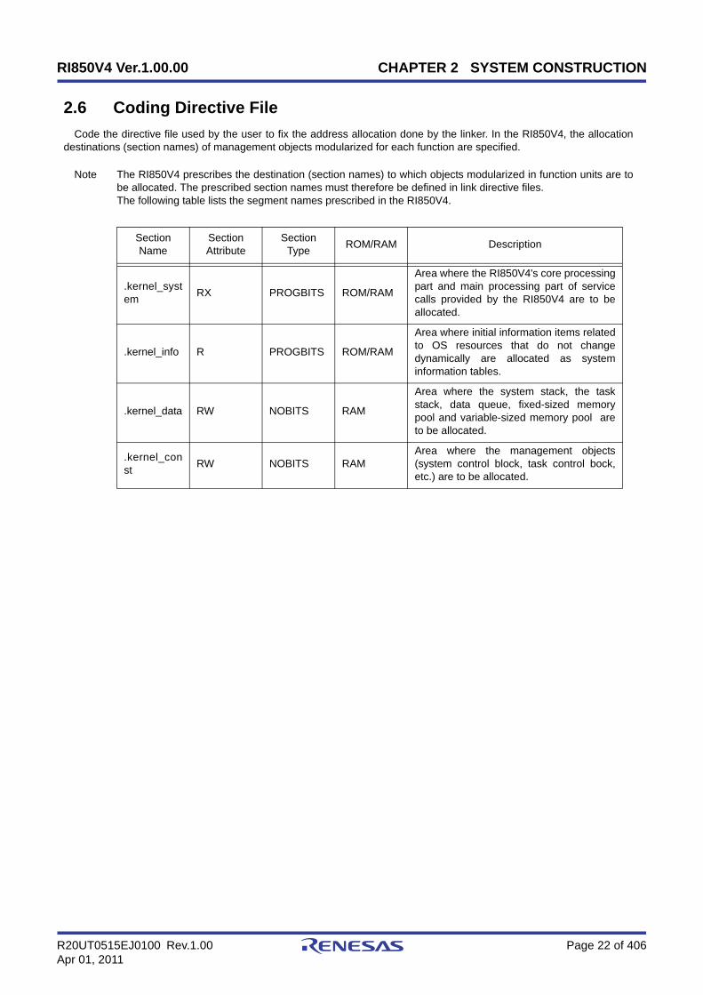
2.6 Coding Directive File
Code the directive file used by the user to fix the address allocation done by the linker. In the RI850V4, the allocationdestinations (section names) of management objects modularized for each function are specified.
Note The RI850V4 prescribes the destination (section names) to which objects modularized in function units are tobe allocated. The prescribed section names must therefore be defined in link directive files.The following table lists the segment names prescribed in the RI850V4.
Section Name
Section Attribute
Section Type ROM/RAM Description
.kernel_system RX PROGBITS ROM/RAM
Area where the RI850V4's core processingpart and main processing part of servicecalls provided by the RI850V4 are to beallocated.
.kernel_info R PROGBITS ROM/RAM
Area where initial information items relatedto OS resources that do not changedynamically are allocated as systeminformation tables.
.kernel_data RW NOBITS RAM
Area where the system stack, the taskstack, data queue, fixed-sized memorypool and variable-sized memory pool areto be allocated.
.kernel_const RW NOBITS RAM
Area where the management objects(system control block, task control bock,etc.) are to be allocated.

RI850V4 Ver.1.00.00 CHAPTER 2 SYSTEM CONSTRUCTION
R20UT0515EJ0100 Rev.1.00 Page 23 of 406Apr 01, 2011
2.7 Creating Load Module
Run a build on CubeSuite+ for files created in sections from "2.2 Coding of Target-Dependent Module" to "2.6 CodingDirective File", and library files provided by the RI850V4 and C compiler package, to create a load module.
1 ) Create or load a projectCreate a new project, or load an existing one.
Note See RI Series Start User's Manual or CubeSuite+ Start User's Manual for details about creating a newproject or loading an existing one.
2 ) Set a build target projectWhen making settings for or running a build, set the active project.If there is no subproject, the project is always active.
Note See CubeSuite+ V850 Build / CubeSuite+ Build for CX Compiler User's Manual for details about settingthe active project.
3 ) Confirm the versionSelect the Realtime OS node on the project tree to open the Property panel.Confirm the version of RI850V4 to be used in the [Kernel version] property on the [RI850V4] tab.
Figure 2-2 Property Panel: [RI850V4] Tab
4 ) Set build target filesFor the project, add or remove build target files and update the dependencies.
Note See CubeSuite+ V850 Build / CubeSuite+ Build for CX Compiler User's Manual for details about adding orremoving build target files for the project and updating the dependencies.
The following lists the files required for creating a load module.
- Library files created in "2.2.1 Creating target-dependent module library"
- Target-dependent module library
- C/assembly language source files created in "2.3 Coding Processing Programs"
- Processing programs (tasks, task exception handling routines, cyclic handlers, interrupt handlers, extendedservice call routines, CPU exception handlers)
- System configuration file created in "2.4 Coding System Configuration File"
- SYSTEM CONFIGURATION FILE

RI850V4 Ver.1.00.00 CHAPTER 2 SYSTEM CONSTRUCTION
R20UT0515EJ0100 Rev.1.00 Page 24 of 406Apr 01, 2011
Note Specify "cfg" as the extention of the system configuration file name.If the extension is different, "cfg" isautomatically added (for example, if you designate "aaa.c" as a file name, the file is named as"aaa.c.cfg").
- C/assembly language source files created in "2.5 Coding User-Own Coding Module"
- User-own coding module (initialization routine, idle routine, boot processing)
- Link directive file created in "2.6 Coding Directive File"
- Link directive file
- Library files provided by the RI850V4
- Kernel library
- Library files provided by the C compiler package
- Standard library, runtime library, etc.
Note 1 If the system configuration file is added to the Project Tree panel, the Realtime OS generated files node isappeared.The following information files are appeared under the Realtime OS generated files node. However, thesefiles are not generated at this point in time.
- System information table file
- System information header file
- Entry file
Figure 2-3 Project Tree Panel (After Adding sys.cfg)
Note 2 When replacing the system configuration file, first remove the added system configuration file from theproject, then add another one again.

RI850V4 Ver.1.00.00 CHAPTER 2 SYSTEM CONSTRUCTION
R20UT0515EJ0100 Rev.1.00 Page 25 of 406Apr 01, 2011
Note 3 Although it is possible to add more than one system configuration files to a project, only the first file addedis enabled. Note that if you remove the enabled file from the project, the remaining additional files will notbe enabled; you must therefore add them again.
5 ) Set the output of information filesSelect the system configuration file on the project tree to open the Property panel.On the [System Configuration File Related Information] tab, set the output of information files (system informationtable file, system information header file, and entry file).
Figure 2-4 Property Panel: [System Configuration File Related Information] Tab
6 ) Specify the output of a load module fileSet the output of a load module file as the product of the build.
Note See CubeSuite+ V850 Build / CubeSuite+ Build for CX Compiler User's Manual for details aboutspecifying the output of a load module file.
7 ) Set build optionsSet the options for the compiler, assembler, linker, and the like.
Note See CubeSuite+ V850 Build / CubeSuite+ Build for CX Compiler User's Manual for details about settingbuild options.

RI850V4 Ver.1.00.00 CHAPTER 2 SYSTEM CONSTRUCTION
R20UT0515EJ0100 Rev.1.00 Page 26 of 406Apr 01, 2011
8 ) Run a buildRun a build to create a load module.
Note See CubeSuite+ V850 Build / CubeSuite+ Build for CX Compiler User's Manual for details about runnig abuild.
Figure 2-5 Project Tree Panel (After Running Build)
9 ) Save the projectSave the setting information of the project to the project file.
Note See CubeSuite+ Start User's Manual for details about saving the project.
RI850V4 Ver.1.00.00 CHAPTER 3 TASK MANAGEMENT FUNCTIONS
R20UT0515EJ0100 Rev.1.00 Page 27 of 406Apr 01, 2011
CHAPTER 3 TASK MANAGEMENT FUNCTIONS
This chapter describes the task management functions performed by the RI850V4.
3.1 Outline
The task management functions provided by the RI850V4 include a function to reference task statuses such as prioritiesand detailed task information, in addition to a function to manipulate task statuses such as generation, activation andtermination of tasks.
3.2 Tasks
A task is processing program that is not executed unless it is explicitly manipulated via service calls provided by theRI850V4, unlike other processing programs (cyclic handler and interrupt handler), and is called from the scheduler.
The RI850V4 manages the states in which each task may enter and tasks themselves, by using management objects(task management blocks) corresponding to tasks one-to-one.
Note The execution environment information required for a task's execution is called "task context". During taskexecution switching, the task context of the task currently under execution by the RI850V4 is saved and thetask context of the next task to be executed is loaded.
3.2.1 Task state
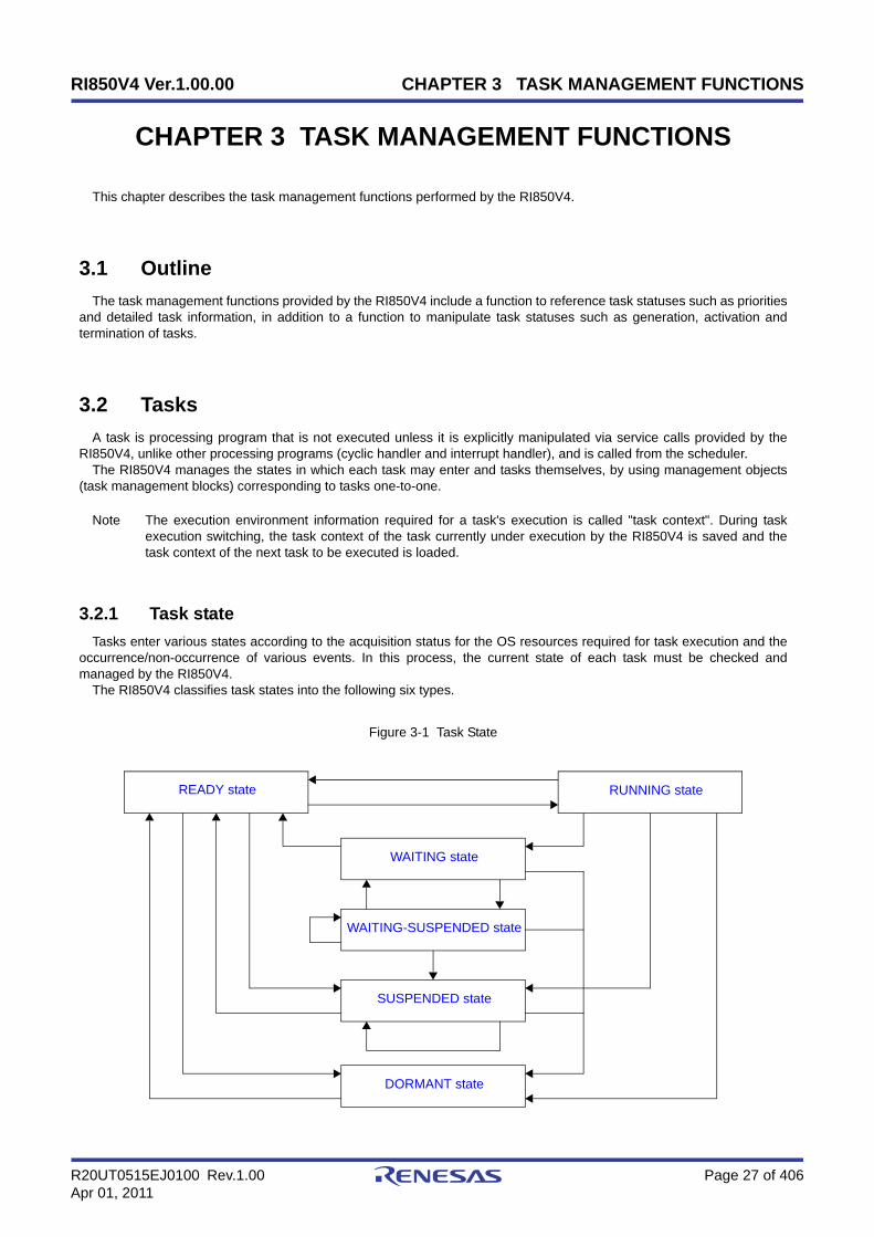
Tasks enter various states according to the acquisition status for the OS resources required for task execution and theoccurrence/non-occurrence of various events. In this process, the current state of each task must be checked andmanaged by the RI850V4.
The RI850V4 classifies task states into the following six types.
Figure 3-1 Task State
WAITING state
WAITING-SUSPENDED state
SUSPENDED state
DORMANT state
RUNNING stateREADY state

RI850V4 Ver.1.00.00 CHAPTER 3 TASK MANAGEMENT FUNCTIONS
R20UT0515EJ0100 Rev.1.00 Page 28 of 406Apr 01, 2011
1 ) DORMANT stateState of a task that is not active, or the state entered by a task whose processing has ended.A task in the DORMANT state, while being under management of the RI850V4, is not subject to RI850V4 scheduling.
2 ) READY stateState of a task for which the preparations required for processing execution have been completed, but since another task with a higher priority level or a task with the same priority level is currently being processed, the task is waiting to be given the CPU's use right.
3 ) RUNNING stateState of a task that has acquired the CPU use right and is currently being processed.Only one task can be in the running state at one time in the entire system.
4 ) WAITING stateState in which processing execution has been suspended because conditions required for execution are not satisfied.Resumption of processing from the WAITING state starts from the point where the processing execution was suspended. The value of information required for resumption (such as task context) immediately before suspension is therefore restored.In the RI850V4, the WAITING state is classified into the following ten types according to their required conditions and managed.
Table 3-1 WAITING State
5 ) SUSPENDED stateState in which processing execution has been suspended forcibly.Resumption of processing from the SUSPENDED state starts from the point where the processing execution was suspended. The value of information required for resumption (such as task context) immediately before suspension is therefore restored.
WAITING State Description
Sleeping stateA task enters this state if the counter for the task (registering thenumber of times the wakeup request has been issued) indicates 0x0upon the issuance of a slp_tsk or tslp_tsk.
Delayed state A task enters this state upon the issuance of a dly_tsk.
WAITING state for a semaphoreresource
A task enters this state if it cannot acquire a resource from therelevant semaphore upon the issuance of a wai_sem or twai_sem.
WAITING state for an eventflag A task enters this state if a relevant eventflag does not satisfy apredetermined condition upon the issuance of a wai_flg or twai_flg.
Sending WAITING state for adata queue
A task enters this state if cannot send a data to the relevant dataqueue upon the issuance of a snd_dtq or tsnd_dtq.
Receiving WAITING state for adata queue
A task enters this state if cannot receive a data from the relevantdata queue upon the issuance of a rcv_dtq or trcv_dtq.
Receiving WAITING state for amailbox
A task enters this state if cannot receive a message from therelevant mailbox upon the issuance of a rcv_mbx or trcv_mbx.
WAITING state for a mutex A task enters this state if cannot lock the relevant mutex upon theissuance of a loc_mtx or tloc_mtx.
WAITING state for a fixed-sizedmemory block
A task enters this state if it cannot acquire a fixed-sized memoryblock from the relevant fixed-sized memory pool upon the issuanceof a get_mpf or tget_mpf.
WAITING state for a variable-sized memory block
A task enters this state if it cannot acquire a variable-sized memoryblock from the relevant variable-sized memory pool upon theissuance of a get_mpl or tget_mpl.
RI850V4 Ver.1.00.00 CHAPTER 3 TASK MANAGEMENT FUNCTIONS
R20UT0515EJ0100 Rev.1.00 Page 29 of 406Apr 01, 2011
6 ) WAITING-SUSPENDED stateState in which the WAITING and SUSPENDED states are combined.A task enters the SUSPENDED state when the WAITING state is cancelled, or enters the WAITING state when the SUSPENDED state is cancelled.
3.2.2 Task priority
A priority level that determines the order in which that task will be processed in relation to the other tasks is assigned toeach task.
As a result, in the RI850V4, the task that has the highest priority level of all the tasks that have entered an executablestate (RUNNING state or READY state) is selected and given the CPU use right.
In the RI850V4, the following two types of priorities are used for management purposes.
- Initial priorityPriority set when a task is created.Therefore, the priority level of a task (priority level referenced by the scheduler) immediately after it moves from theDORMANT state to the READY state is the initial priority.
- Current priorityPriority referenced by the RI850V4 when it performs a manipulation (task scheduling, queuing tasks to a wait queue inthe order of priority, or priority level inheritance) when a task is activated.
Note 1 In the RI850V4, a task having a smaller priority number is given a higher priority.
Note 2 The priority range that can be specified in a system can be defined in Basic information (Maximum priority:maxpri) when creating a system configuration file.

RI850V4 Ver.1.00.00 CHAPTER 3 TASK MANAGEMENT FUNCTIONS
R20UT0515EJ0100 Rev.1.00 Page 30 of 406Apr 01, 2011
3.2.3 Basic form of tasks
When coding a task, use a void function with one VP_INT argument (any function name is fine). The extended information specified with Task information, or the start code specified when sta_tsk or ista_tsk is issued,
is set for the exinf argument.The following shows the basic form of tasks in C.
[CA850/CX version]
[CCV850/CCV850E version]
Note 1 If a task moves from the DORMANT state to the READY state by issuing sta_tsk or ista_tsk, the start codespecified when issuing sta_tsk or ista_tsk is set to the exinf argument.
Note 2 When the return instruction is issued in a task, the same processing as ext_tsk is performed.
Note 3 For details about the extended information, refer to "3.4 Activate Task".
#include <kernel.h> /*Standard header file definition*/
#pragma rtos_task task /*#pragma directive definition*/
void task (VP_INT exinf){ /* ......... */
ext_tsk (); /*Terminate invoking task*/}
#include <kernel.h> /*Standard header file definition*/
void task (VP_INT exinf){ /* ......... */
ext_tsk (); /*Terminate invoking task*/}

RI850V4 Ver.1.00.00 CHAPTER 3 TASK MANAGEMENT FUNCTIONS
R20UT0515EJ0100 Rev.1.00 Page 31 of 406Apr 01, 2011
3.2.4 Internal processing of task
In the RI850V4, original dispatch processing (task scheduling) is executed during task switching.Therefore, note the following points when coding tasks.
- Coding methodCode tasks using C or assembly language.When coding in C, they can be coded in the same manner as ordinary functions coded.When coding in assembly language, code them according to the calling rules prescribed in the compiler used.
- Stack switchingWhen switching tasks, the RI850V4 performs switching to the task specified in Task information.
- Service call issuanceService calls that can be issued in tasks are limited to the service calls that can be issued from tasks.
- Acknowledgment of maskable interrupts (the ID flag of PSW)When processing is started (a task changes from DORMANT to RUNNING status, and control transitions to the taskprocess), the maskable-interrupt acknowledgement status differs depending on the initial interrupt status set in theTask information attributes.It is possible to change the maskable interrupt acknowledgement status from inside a process. The changed status isnot passed on when control shifts to the processing program after the task process ends (the task status changesfrom RUNNING to DORMANT).When a process resumes (a task status changes from RUNNING to READY, WAITING, WAITING-SUSPENDED, orSUSPENDED, and then back to RUNNING, and control shifts to the task), the maskable interrupt acknowledgementstatus is returned to the status it had before it was stopped.
Note For details on the valid issuance range of each service call, refer to Table 17-1 to Table 17-14.

RI850V4 Ver.1.00.00 CHAPTER 3 TASK MANAGEMENT FUNCTIONS
R20UT0515EJ0100 Rev.1.00 Page 32 of 406Apr 01, 2011
3.3 Creat Task
In the RI850V4, the method of creating a task is limited to "static creation".Tasks therefore cannot be created dynamically using a method such as issuing a service call from a processing
program.Static task creation means defining of tasks using static API "CRE_TSK" in the system configuration file.For details about the static API "CRE_TSK", refer to "18.5.1 Task information".
3.4 Activate Task
The RI850V4 provides two types of interfaces for task activation: queuing an activation request queuing and notqueuing an activation request.
In the RI850V4, extended information specified in Task information during configuration and the value specified for thesecond parameter stacd when service call sta_tsk or ista_tsk is issued are called "extended information".
3.4.1 Queuing an activation request
A task (queuing an activation request) is activated by issuing the following service call from the processing program.
- act_tsk, iact_tskThese service calls move a task specified by parameter tskid from the DORMANT state to the READY state.As a result, the target task is queued at the end on the ready queue corresponding to the initial priority and becomessubject to scheduling by the RI850V4.If the target task has been moved to a state other than the DORMANT state when this service call is issued, thisservice call does not move the state but increments the activation request counter (by added 0x1 to the wakeuprequest counter).The following describes an example for coding this service call.
[CA850/CX version]
Note 1 The activation request counter managed by the RI850V4 is configured in 7-bit widths. If the number ofactivation requests exceeds the maximum count value 127 as a result of issuing this service call, the countermanipulation processing is therefore not performed but "E_QOVR" is returned.
Note 2 Extended information specified in Task information is passed to the task activated by issuing these servicecalls.
#include <kernel.h> /*Standard header file definition*/
#pragma rtos_task task /*#pragma directive definition*/
void task (VP_INT exinf){ ID tskid = 8; /*Declares and initializes variable*/
/* ......... */
act_tsk (tskid); /*Avtivate task (queues an activation request)*/
/* ......... */}

RI850V4 Ver.1.00.00 CHAPTER 3 TASK MANAGEMENT FUNCTIONS
R20UT0515EJ0100 Rev.1.00 Page 33 of 406Apr 01, 2011
3.4.2 Not queuing an activation request
A task (not queuing an activation request) is activated by issuing the following service call from the processing program.
- sta_tsk, ista_tskThese service calls move a task specified by parameter tskid from the DORMANT state to the READY state.As a result, the target task is queued at the end on the ready queue corresponding to the initial priority and becomessubject to scheduling by the RI850V4.This service call does not perform queuing of activation requests. If the target task is in a state other than theDORMANT state, the status manipulation processing for the target task is therefore not performed but "E_OBJ" isreturned.Specify for parameter stacd the extended information transferred to the target task.The following describes an example for coding this service call.
[CA850/CX version]
#include <kernel.h> /*Standard header file definition*/
#pragma rtos_task task /*#pragma directive definition*/
void task (VP_INT exinf){ ID tskid = 8; /*Declares and initializes variable*/ VP_INT stacd = 123; /*Declares and initializes variable*/
/* ......... */
sta_tsk (tskid, stacd); /*Activate task (does not queue an activation */ /*request)*/
/* ......... */}

RI850V4 Ver.1.00.00 CHAPTER 3 TASK MANAGEMENT FUNCTIONS
R20UT0515EJ0100 Rev.1.00 Page 34 of 406Apr 01, 2011
3.5 Cancel Task Activation Requests
An activation request is cancelled by issuing the following service call from the processing program.
- can_act, ican_actThis service call cancels all of the activation requests queued to the task specified by parameter tskid (sets theactivation request counter to 0x0).When this service call is terminated normally, the number of cancelled activation requests is returned.The following describes an example for coding this service call.
[CA850/CX version]
Note This service call does not perform status manipulation processing but performs the setting of activationrequest counter. Therefore, the task does not move from a state such as the READY state to the DORMANTstate.
#include <kernel.h> /*Standard header file definition*/
#pragma rtos_task task /*#pragma directive definition*/
void task (VP_INT exinf){ ER_UINT ercd; /*Declares variable*/ ID tskid = 8; /*Declares and initializes variable*/
/* ......... */
ercd = can_act (tskid); /*Cancel task activation requests*/
if (ercd >= 0x0) { /* ......... */ /*Normal termination processing*/ }
/* ......... */}
RI850V4 Ver.1.00.00 CHAPTER 3 TASK MANAGEMENT FUNCTIONS
R20UT0515EJ0100 Rev.1.00 Page 35 of 406Apr 01, 2011
3.6 Terminate Task
3.6.1 Terminate invoking task
An invoking task is terminated by issuing the following service call from the processing program.
- ext_tskThis service call moves an invoking task from the RUNNING state to the DORMANT state.As a result, the invoking task is unlinked from the ready queue and excluded from the RI850V4 scheduling subject.If an activation request has been queued to the invoking task (the activation request counter is not set to 0x0) whenthis service call is issued, this service call moves the task from the RUNNING state to the DORMANT state,decrements the wakeup request counter (by subtracting 0x1 from the wakeup request counter), and then moves thetask from the DORMANT state to the READY state.The following describes an example for coding this service call.
[CA850/CX version]
Note 1 When moving a task from the RUNNING state to the DORMANT state, this service call initializes thefollowing information to values that are set during task creation.
- Priority (current priority)
- Wakeup request count
- Suspension count
- Interrupt status
If an invoking task has locked a mutex, the locked state is released at the same time (processing equivalentto unl_mtx).
Note 2 When the return instruction is issued in a task, the same processing as ext_tsk is performed.
#include <kernel.h> /*Standard header file definition*/
#pragma rtos_task task /*#pragma directive definition*/
void task (VP_INT exinf){ /* ......... */
ext_tsk (); /*Terminate invoking task*/}

RI850V4 Ver.1.00.00 CHAPTER 3 TASK MANAGEMENT FUNCTIONS
R20UT0515EJ0100 Rev.1.00 Page 36 of 406Apr 01, 2011
3.6.2 Terminate task
Other tasks are forcibly terminated by issuing the following service call from the processing program.
- ter_tskThis service call forcibly moves a task specified by parameter tskid to the DORMANT state.As a result, the target task is excluded from the RI850V4 scheduling subject.If an activation request has been queued to the target task (the activation request counter is not set to 0x0) when thisservice call is issued, this service call moves the task to the DORMANT state, decrements the wakeup requestcounter (by subtracting 0x1 from the wakeup request counter), and then moves the task from the DORMANT state tothe READY state.The following describes an example for coding this service call.
[CA850/CX version]
Note When moving a task to the DORMANT state, this service call initializes the following information to valuesthat are set during task creation.
- Priority (current priority)
- Wakeup request count
- Suspension count
- Interrupt status
If the target task has locked a mutex, the locked state is released at the same time (processing equivalent tounl_mtx).
#include <kernel.h> /*Standard header file definition*/
#pragma rtos_task task /*#pragma directive definition*/
void task (VP_INT exinf){ ID tskid = 8; /*Declares and initializes variable*/
/* ......... */
ter_tsk (tskid); /*Terminate task*/
/* ......... */}

RI850V4 Ver.1.00.00 CHAPTER 3 TASK MANAGEMENT FUNCTIONS
R20UT0515EJ0100 Rev.1.00 Page 37 of 406Apr 01, 2011
3.7 Change Task Priority
The priority is changed by issuing the following service call from the processing program.
- chg_pri, ichg_priThese service calls change the priority of the task specified by parameter tskid (current priority) to a value specified byparameter tskpri.If the target task is in the RUNNING or READY state after this service call is issued, this service call re-queues thetask at the end of the ready queue corresponding to the priority specified by parameter tskpri, following prioritychange processing.The following describes an example for coding this service call.
[CA850/CX version]
Note When the target task is queued to a wait queue in the order of priority, the wait order may change due toissuance of this service call.
Example When three tasks (task A: priority level 10, task B: priority level 11, task C: priority level 12) arequeued to the semaphore wait queue in the order of priority, and the priority level of task B ischanged from 11 to 9, the wait order will be changed as follows.
#include <kernel.h> /*Standard header file definition*/
#pragma rtos_task task /*#pragma directive definition*/
void task (VP_INT exinf){ ID tskid = 8; /*Declares and initializes variable*/ PRI tskpri = 9; /*Declares and initializes variable*/
/* ......... */
chg_pri (tskid, tskpri); /*Change task priority*/
/* ......... */}
Task CSemaphore
Task ATask B
chg_pri (Task B, 9);
Priority: 9 Priority: 10 Priority: 12
Task CSemaphore
Task BTask APriority: 10 Priority: 11 Priority: 12
Task CPriority: 12

RI850V4 Ver.1.00.00 CHAPTER 3 TASK MANAGEMENT FUNCTIONS
R20UT0515EJ0100 Rev.1.00 Page 38 of 406Apr 01, 2011
3.8 Reference Task Priority
A task priority is referenced by issuing the following service call from the processing program.
- get_pri, iget_priStores current priority of the task specified by parameter tskid in the area specified by parameter p_tskpri.The following describes an example for coding this service call.
[CA850/CX version]
#include <kernel.h> /*Standard header file definition*/
#pragma rtos_task task /*#pragma directive definition*/
void task (VP_INT exinf){ ID tskid = 8; /*Declares and initializes variable*/ PRI p_tskpri; /*Declares variable*/
/* ......... */
get_pri (tskid, &p_tskpri); /*Reference task priority*/
/* ......... */}
RI850V4 Ver.1.00.00 CHAPTER 3 TASK MANAGEMENT FUNCTIONS
R20UT0515EJ0100 Rev.1.00 Page 39 of 406Apr 01, 2011
3.9 Reference Task State
3.9.1 Reference task state
A task status is referenced by issuing the following service call from the processing program.
- ref_tsk, iref_tskStores task state packet (current state, current priority, etc.) of the task specified by parameter tskid in the areaspecified by parameter pk_rtsk.The following describes an example for coding this service call.
[CA850/CX version]
Note For details about the task state packet, refer to "16.2.1 Task state packet".
#include <kernel.h> /*Standard header file definition*/
#pragma rtos_task task /*#pragma directive definition*/
void task (VP_INT exinf){ ID tskid = 8; /*Declares and initializes variable*/ T_RTSK pk_rtsk; /*Declares data structure*/ STAT tskstat; /*Declares variable*/ PRI tskpri; /*Declares variable*/ STAT tskwait; /*Declares variable*/ ID wobjid; /*Declares variable*/ TMO lefttmo; /*Declares variable*/ UINT actcnt; /*Declares variable*/ UINT wupcnt; /*Declares variable*/ UINT suscnt; /*Declares variable*/ ATR tskatr; /*Declares variable*/ PRI itskpri; /*Declares variable*/
/* ......... */
ref_tsk (tskid, &pk_rtsk); /*Reference task state*/
tskstat = pk_rtsk.tskstat; /*Reference current state*/ tskpri = pk_rtsk.tskpri; /*Reference current priority*/ tskwait = pk_rtsk.tskwait; /*Reference reason for waiting*/ wobjid = pk_rtsk.wobjid; /*Reference object ID number for which the */ /*task is waiting*/ lefttmo = pk_rtsk.lefttmo; /*Reference remaining time until timeout*/ actcnt = pk_rtsk.actcnt; /*Reference activation request count*/ wupcnt = pk_rtsk.wupcnt; /*Reference wakeup request count*/ suscnt = pk_rtsk.suscnt; /*Reference suspension count*/ tskatr = pk_rtsk.tskatr; /*Reference attribute*/ itskpri = pk_rtsk.itskpri; /*Reference initial priority*/
/* ......... */}
RI850V4 Ver.1.00.00 CHAPTER 3 TASK MANAGEMENT FUNCTIONS
R20UT0515EJ0100 Rev.1.00 Page 40 of 406Apr 01, 2011
3.9.2 Reference task state (simplified version)
A task status (simplified version) is referenced by issuing the following service call from the processing program.
- ref_tst, iref_tstStores task state packet (current state, reason for waiting) of the task specified by parameter tskid in the areaspecified by parameter pk_rtst.Used for referencing only the current state and reason for wait among task information.Response becomes faster than using ref_tsk or iref_tsk because only a few information items are acquired.The following describes an example for coding this service call.
[CA850/CX version]
Note For details about the task state packet (simplified version), refer to "16.2.2 Task state packet (simplifiedversion)".
#include <kernel.h> /*Standard header file definition*/
#pragma rtos_task task /*#pragma directive definition*/
void task (VP_INT exinf){ ID tskid = 8; /*Declares and initializes variable*/ T_RTST pk_rtst; /*Declares data structure*/ STAT tskstat; /*Declares variable*/ STAT tskwait; /*Declares variable*/
/* ......... */
ref_tst (tskid, &pk_rtst); /*Reference task state (simplified version)*/
tskstat = pk_rtst.tskstat; /*Reference current state*/ tskwait = pk_rtst.tskwait; /*Reference reason for waiting*/
/* ......... */}

RI850V4 Ver.1.00.00 CHAPTER 3 TASK MANAGEMENT FUNCTIONS
R20UT0515EJ0100 Rev.1.00 Page 41 of 406Apr 01, 2011
3.10 Target-Dependent Module
To support various execution environments, the RI850V4 extracts processing performed when a stack required by theRI850V4 or the processing program to perform execution overflows, from the memory pool management function, as atarget-dependent module. This prevents inadvertent program loops in the system caused by a stack overflow.
Note The RI850V4 checks the stack overflow only when TA_ON (overflow is checked) is defined in Basicinformation during configuration.
3.10.1 Post-overflow processing
This is a routine dedicated to post-overflow processing, which is extracted as a target-dependent module, for executingpost processing when a stack required by the RI850V4 or the processing program to perform execution overflows. It iscalled from the RI850V4 when a stack overflows.
- Basic form of post-overflow processingCode post-overflow processing by using the void type function (function name: _kernel_stk_overflow) that has twoINT type arguments.The "value of stack pointer sp when a stack overflow is detected" is set to argument r6, and the "value of programcounter pc when a stack overflow is detected" is set to argument r7.The following shows the basic form of coding post-overflow processing in assembly language.
[CA850/CX version, CCV850/CCV850E version]
- Processing performed during post-overflow processingPost-overflow processing is a routine dedicated to post processing, which is extracted as a target-dependent module,for executing post processing when a stack required by the RI850V4 or the processing program to perform executionoverflows. Therefore, note the following points when coding post-overflow processing.
- Coding methodCode post-overflow processing using C or assembly language.When coding in C, they can be coded in the same manner as ordinary functions coded.When coding in assembly language, code them according to the calling rules prescribed in the compiler used.
- Stack switchingThe RI850V4 does not perform the processing related to stack switching when passing control to post-overflowprocessing.When using the system stack specified in Basic information, the code regarding stack switching must thereforebe written in post-overflow processing.
- Service call issuanceIssuance of service calls is prohibited during post-overflow processing because the normal operation cannot beguaranteed.
The following lists processing that should be executed in post-overflow processing.
- Post-processing that handles stack overflows
#include <kernel.h> /*Standard header file definition*/
.text .align 0x4 .globl __kernel_stk_overflow__kernel_stk_overflow :
/* ......... */
.halt_loop : jbr .halt_loop

RI850V4 Ver.1.00.00 CHAPTER 3 TASK MANAGEMENT FUNCTIONS
R20UT0515EJ0100 Rev.1.00 Page 42 of 406Apr 01, 2011
Note The detailed operations (such as reset) that should be coded as post-overflow processing depends on theuser system.
3.11 Memory Saving
The RI850V4 provides the method (Disable preempt) for reducing the task stack size required by tasks to performprocessing.
3.11.1 Disable preempt
In the RI850V4, preempt acknowledge status attribute TA_DISPREEMPT can be defined in Task information whencreating a system configuration file.
The task for which this attribute is defined performs the operation that continues processing by ignoring the schedulingrequest issued from a non-task, so a management area of 24 to 44 bytes can be reduced per task.

RI850V4 Ver.1.00.00 CHAPTER 4 TASK DEPENDENT SYNCHRONIZATION FUNCTIONS
R20UT0515EJ0100 Rev.1.00 Page 43 of 406Apr 01, 2011
CHAPTER 4 TASK DEPENDENT SYNCHRONIZATION FUNCTIONS
This chapter describes the task dependent synchronization functions performed by the RI850V4.
4.1 Outline
The RI850V4 provides several task-dependent synchronization functions.
4.2 Put Task to Sleep
4.2.1 Waiting forever
A task is moved to the sleeping state (waiting forever) by issuing the following service call from the processing program.
- slp_tskAs a result, the invoking task is unlinked from the ready queue and excluded from the RI850V4 scheduling subject.If a wakeup request has been queued to the target task (the wakeup request counter is not set to 0x0) when thisservice call is issued, this service call does not move the state but decrements the wakeup request counter (bysubtracting 0x1 from the wakeup request counter).The sleeping state is cancelled in the following cases, and then moved to the READY state.
The following describes an example for coding this service call.
[CA850/CX version]
Sleeping State Cancel Operation Return Value
A wakeup request was issued as a result of issuing wup_tsk. E_OK
A wakeup request was issued as a result of issuing iwup_tsk. E_OK
Forced release from waiting (accept rel_wai while waiting). E_RLWAI
Forced release from waiting (accept irel_wai while waiting). E_RLWAI
#include <kernel.h> /*Standard header file definition*/#pragma rtos_task task /*#pragma directive definition*/
void task (VP_INT exinf){ ER ercd; /*Declares variable*/
/* ......... */
ercd = slp_tsk (); /*Put task to sleep (waiting forever)*/
if (ercd == E_OK) { /* ......... */ /*Normal termination processing*/ } else if (ercd == E_RLWAI) { /* ......... */ /*Forced termination processing*/ }
RI850V4 Ver.1.00.00 CHAPTER 4 TASK DEPENDENT SYNCHRONIZATION FUNCTIONS
R20UT0515EJ0100 Rev.1.00 Page 44 of 406Apr 01, 2011
/* ......... */}

RI850V4 Ver.1.00.00 CHAPTER 4 TASK DEPENDENT SYNCHRONIZATION FUNCTIONS
R20UT0515EJ0100 Rev.1.00 Page 45 of 406Apr 01, 2011
4.2.2 With timeout
A task is moved to the sleeping state (with timeout) by issuing the following service call from the processing program.
- tslp_tskThis service call moves an invoking task from the RUNNING state to the WAITING state (sleeping state).As a result, the invoking task is unlinked from the ready queue and excluded from the RI850V4 scheduling subject.If a wakeup request has been queued to the target task (the wakeup request counter is not set to 0x0) when thisservice call is issued, this service call does not move the state but decrements the wakeup request counter (bysubtracting 0x1 from the wakeup request counter).The sleeping state is cancelled in the following cases, and then moved to the READY state.
The following describes an example for coding this service call.
[CA850/CX version]
Note When TMO_FEVR is specified for wait time tmout, processing equivalent to slp_tsk will be executed.
Sleeping State Cancel Operation Return Value
A wakeup request was issued as a result of issuing wup_tsk. E_OK
A wakeup request was issued as a result of issuing iwup_tsk. E_OK
Forced release from waiting (accept rel_wai while waiting). E_RLWAI
Forced release from waiting (accept irel_wai while waiting). E_RLWAI
Polling failure or timeout. E_TMOUT
#include <kernel.h> /*Standard header file definition*/
#pragma rtos_task task /*#pragma directive definition*/
void task (VP_INT exinf){ ER ercd; /*Declares variable*/ TMO tmout = 3600; /*Declares and initializes variable*/
/* ......... */
ercd = tslp_tsk (tmout); /*Put task to sleep (with timeout)*/
if (ercd == E_OK) { /* ......... */ /*Normal termination processing*/ } else if (ercd == E_RLWAI) { /* ......... */ /*Forced termination processing*/ } else if (ercd == E_TMOUT) { /* ......... */ /*Timeout processing*/ }
/* ......... */}
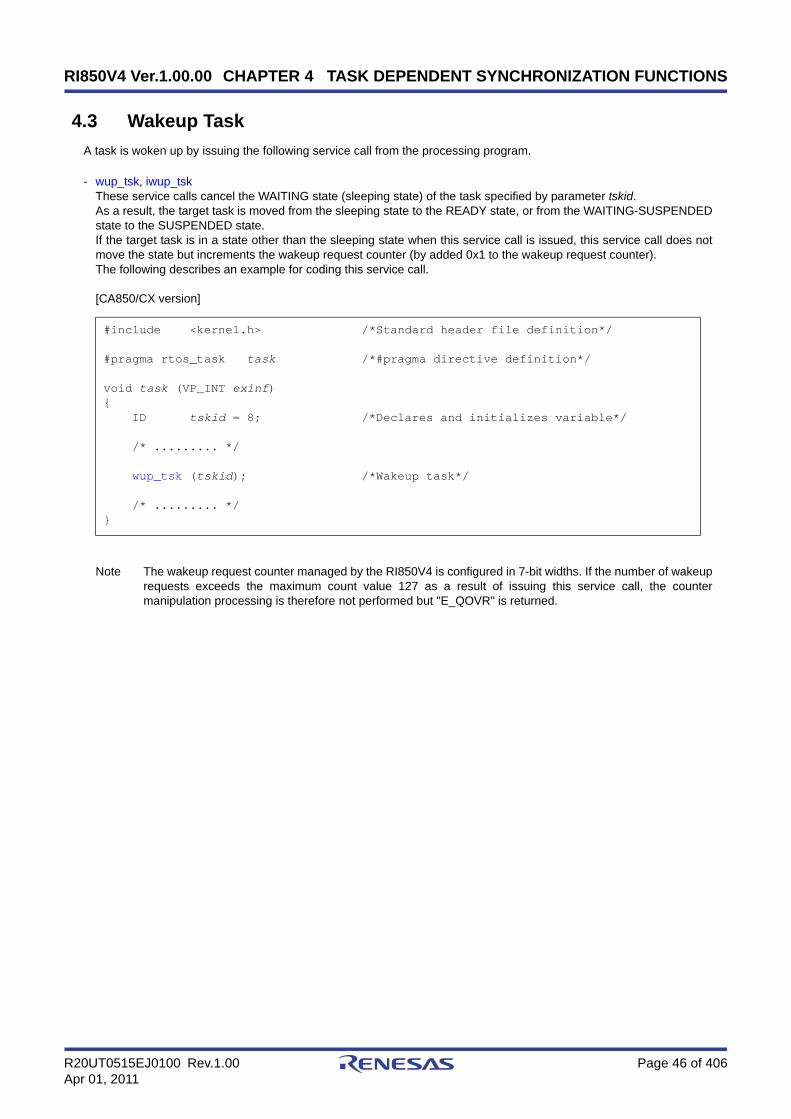
RI850V4 Ver.1.00.00 CHAPTER 4 TASK DEPENDENT SYNCHRONIZATION FUNCTIONS
R20UT0515EJ0100 Rev.1.00 Page 46 of 406Apr 01, 2011
4.3 Wakeup Task
A task is woken up by issuing the following service call from the processing program.
- wup_tsk, iwup_tskThese service calls cancel the WAITING state (sleeping state) of the task specified by parameter tskid.As a result, the target task is moved from the sleeping state to the READY state, or from the WAITING-SUSPENDEDstate to the SUSPENDED state.If the target task is in a state other than the sleeping state when this service call is issued, this service call does notmove the state but increments the wakeup request counter (by added 0x1 to the wakeup request counter).The following describes an example for coding this service call.
[CA850/CX version]
Note The wakeup request counter managed by the RI850V4 is configured in 7-bit widths. If the number of wakeuprequests exceeds the maximum count value 127 as a result of issuing this service call, the countermanipulation processing is therefore not performed but "E_QOVR" is returned.
#include <kernel.h> /*Standard header file definition*/
#pragma rtos_task task /*#pragma directive definition*/
void task (VP_INT exinf){ ID tskid = 8; /*Declares and initializes variable*/
/* ......... */
wup_tsk (tskid); /*Wakeup task*/
/* ......... */}
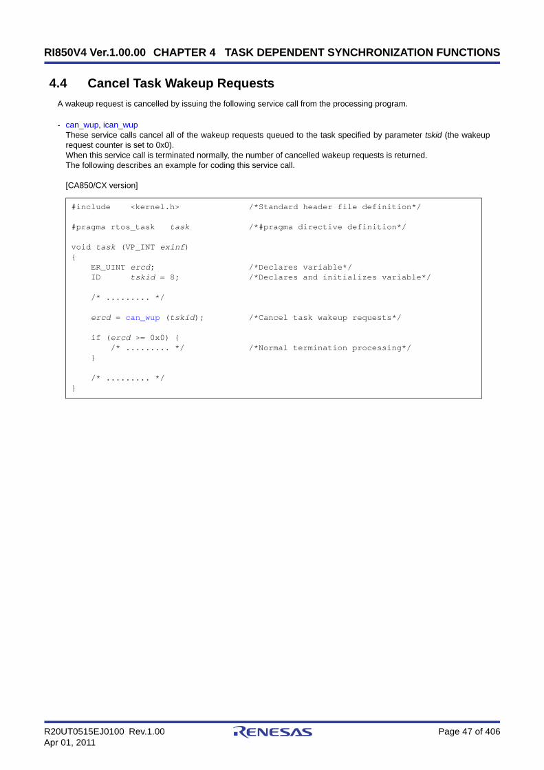
RI850V4 Ver.1.00.00 CHAPTER 4 TASK DEPENDENT SYNCHRONIZATION FUNCTIONS
R20UT0515EJ0100 Rev.1.00 Page 47 of 406Apr 01, 2011
4.4 Cancel Task Wakeup Requests
A wakeup request is cancelled by issuing the following service call from the processing program.
- can_wup, ican_wupThese service calls cancel all of the wakeup requests queued to the task specified by parameter tskid (the wakeuprequest counter is set to 0x0).When this service call is terminated normally, the number of cancelled wakeup requests is returned.The following describes an example for coding this service call.
[CA850/CX version]
#include <kernel.h> /*Standard header file definition*/
#pragma rtos_task task /*#pragma directive definition*/
void task (VP_INT exinf){ ER_UINT ercd; /*Declares variable*/ ID tskid = 8; /*Declares and initializes variable*/
/* ......... */
ercd = can_wup (tskid); /*Cancel task wakeup requests*/
if (ercd >= 0x0) { /* ......... */ /*Normal termination processing*/ }
/* ......... */}

RI850V4 Ver.1.00.00 CHAPTER 4 TASK DEPENDENT SYNCHRONIZATION FUNCTIONS
R20UT0515EJ0100 Rev.1.00 Page 48 of 406Apr 01, 2011
4.5 Release Task from Waiting
The WAITING state is forcibly cancelled by issuing the following service call from the processing program.
- rel_wai, irel_waiThese service calls forcibly cancel the WAITING state of the task specified by parameter tskid.As a result, the target task unlinked from the wait queue and is moved from the WAITING state to the READY state, orfrom the WAITING-SUSPENDED state to the SUSPENDED state."E_RLWAI" is returned from the service call that triggered the move to the WAITING state (slp_tsk, wai_sem, or thelike) to the task whose WAITING state is cancelled by this service call.The following describes an example for coding this service call.
[CA850/CX version]
Note 1 This service call does not perform queuing of forced cancellation requests. If the target task is in a stateother than the WAITING or WAITING-SUSPENDED state, "E_OBJ" is returned.
Note 2 The SUSPENDED state is not cancelled by these service calls.
#include <kernel.h> /*Standard header file definition*/
#pragma rtos_task task /*#pragma directive definition*/
void task (VP_INT exinf){ ID tskid = 8; /*Declares and initializes variable*/
/* ......... */
rel_wai (tskid); /*Release task from waiting*/
/* ......... */}

RI850V4 Ver.1.00.00 CHAPTER 4 TASK DEPENDENT SYNCHRONIZATION FUNCTIONS
R20UT0515EJ0100 Rev.1.00 Page 49 of 406Apr 01, 2011
4.6 Suspend Task
A task is moved to the SUSPENDED state by issuing the following service call from the processing program.
- sus_tsk, isus_tskThese service calls add 0x1 to the suspend request counter for the task specified by parameter tskid, and then movethe target task from the RUNNING state to the SUSPENDED state, from the READY state to the SUSPENDED state,or from the WAITING state to the WAITING-SUSPENDED state.If the target task has moved to the SUSPENDED or WAITING-SUSPENDED state when this service call is issued, thecounter manipulation processing is not performed but only the suspend request counter increment processing isexecuted.The following describes an example for coding this service call.
[CA850/CX version]
Note The suspend request counter managed by the RI850V4 is configured in 7-bit widths. If the number ofsuspend requests exceeds the maximum count value 127 as a result of issuing this service call, the countermanipulation processing is therefore not performed but "E_QOVR" is returned.
#include <kernel.h> /*Standard header file definition*/
#pragma rtos_task task /*#pragma directive definition*/
void task (VP_INT exinf){ ID tskid = 8; /*Declares and initializes variable*/
/* ......... */
sus_tsk (tskid); /*Suspend task*/
/* ......... */}

RI850V4 Ver.1.00.00 CHAPTER 4 TASK DEPENDENT SYNCHRONIZATION FUNCTIONS
R20UT0515EJ0100 Rev.1.00 Page 50 of 406Apr 01, 2011
4.7 Resume Suspended Task
4.7.1 Resume suspended task
The SUSPENDED state is cancelled by issuing the following service call from the processing program.
- rsm_tsk, irsm_tskThis service call subtracts 0x1 from the suspend request counter for the task specified by parameter tskid, and thencancels the SUSPENDED state of the target task.As a result, the target task is moved from the SUSPENDED state to the READY state, or from the WAITING-SUSPENDED state to the WAITING state.If a suspend request is queued (subtraction result is other than 0x0) when this service call is issued, the countermanipulation processing is not performed but only the suspend request counter decrement processing is executed.The following describes an example for coding this service call.
[CA850/CX version]
Note This service call does not perform queuing of cancellation requests. If the target task is in a state other thanthe SUSPENDED or WAITING-SUSPENDED state, "E_OBJ" is therefore returned.
#include <kernel.h> /*Standard header file definition*/
#pragma rtos_task task /*#pragma directive definition*/
void task (VP_INT exinf){ ID tskid = 8; /*Declares and initializes variable*/
/* ......... */
rsm_tsk (tskid); /*Resume suspended task*/
/* ......... */}

RI850V4 Ver.1.00.00 CHAPTER 4 TASK DEPENDENT SYNCHRONIZATION FUNCTIONS
R20UT0515EJ0100 Rev.1.00 Page 51 of 406Apr 01, 2011
4.7.2 Forcibly resume suspended task
The SUSPENDED state is forcibly cancelled by issuing the following service calls from the processing program.
- frsm_tsk, ifrsm_tskThese service calls cancel all of the suspend requests issued for the task specified by parameter tskid (by setting thesuspend request counter to 0x0). As a result, the target task moves from the SUSPENDED state to the READY state,or from the WAITING-SUSPENDED state to the WAITING state.The following describes an example for coding this service call.
[CA850/CX version]
Note This service call does not perform queuing of cancellation requests. If the target task is in a state other thanthe SUSPENDED or WAITING-SUSPENDED state, "E_OBJ" is therefore returned.
#include <kernel.h> /*Standard header file definition*/
#pragma rtos_task task /*#pragma directive definition*/
void task (VP_INT exinf){ ID tskid = 8; /*Declares and initializes variable*/
/* ......... */
frsm_tsk (tskid); /*Forcibly resume suspended task*/
/* ......... */}
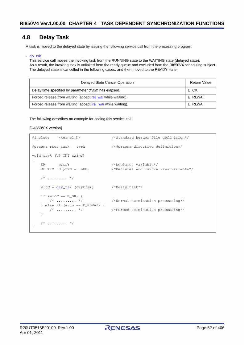
RI850V4 Ver.1.00.00 CHAPTER 4 TASK DEPENDENT SYNCHRONIZATION FUNCTIONS
R20UT0515EJ0100 Rev.1.00 Page 52 of 406Apr 01, 2011
4.8 Delay Task
A task is moved to the delayed state by issuing the following service call from the processing program.
- dly_tskThis service call moves the invoking task from the RUNNING state to the WAITING state (delayed state).As a result, the invoking task is unlinked from the ready queue and excluded from the RI850V4 scheduling subject.The delayed state is cancelled in the following cases, and then moved to the READY state.
The following describes an example for coding this service call.
[CA850/CX version]
Delayed State Cancel Operation Return Value
Delay time specified by parameter dlytim has elapsed. E_OK
Forced release from waiting (accept rel_wai while waiting). E_RLWAI
Forced release from waiting (accept irel_wai while waiting). E_RLWAI
#include <kernel.h> /*Standard header file definition*/
#pragma rtos_task task /*#pragma directive definition*/
void task (VP_INT exinf){ ER ercd; /*Declares variable*/ RELTIM dlytim = 3600; /*Declares and initializes variable*/
/* ......... */
ercd = dly_tsk (dlytim); /*Delay task*/
if (ercd == E_OK) { /* ......... */ /*Normal termination processing*/ } else if (ercd == E_RLWAI) { /* ......... */ /*Forced termination processing*/ }
/* ......... */}

RI850V4 Ver.1.00.00 CHAPTER 4 TASK DEPENDENT SYNCHRONIZATION FUNCTIONS
R20UT0515EJ0100 Rev.1.00 Page 53 of 406Apr 01, 2011
4.9 Differences Between Wakeup Wait with Timeout and Time ElapseWait
Wakeup waits with timeout and time elapse waits differ on the following points.
Table 4-1 Differences Between Wakeup Wait with Timeout and Time Elapse Wait
Wakeup Wait with Timeout Time Elapse Wait
Service call that causes status change tslp_tsk dly_tsk
Return value when timed out E_TMOUT E_OK
Operation when wup_tsk or iwup_tskis issued Wakeup Queues the wakeup request (time
elapse wait is not cancelled).

RI850V4 Ver.1.00.00 CHAPTER 5 TASK EXCEPTION HANDLING FUNCTIONS
R20UT0515EJ0100 Rev.1.00 Page 54 of 406Apr 01, 2011
CHAPTER 5 TASK EXCEPTION HANDLING FUNCTIONS
This chapter describes the task exception handling functions performed by the RI850V4.
5.1 Outline
The task exception handling functions of the RI850V4 include a function related to the task exception handling routinethat is activated when a task exception handling request is issued (function for manipulating or referencing the taskexception handling routine status).
5.2 Task Exception Handling Routines
The task exception handling routine is a routine dedicated to task exception handling, and is activated when a taskexception handling request is issued.
The RI850V4 positions task exception handling routines as extensions of the task for which a task exception handlingrequest is issued. A task exception handling routine is therefore activated when the task for which a task exceptionhandling request is issued moves to the RUNNING state.
The RI850V4 manages the states in which each task exception handling routine may enter and task exception handlingroutines themselves, by using management objects (task exception handling routines contained in task managementblocks) corresponding to task exception handling routines one-to-one.
Note Task exception handling is enabled when a task exception handling routine is activated.
5.2.1 Basic form of task exception handling routines
Code task exception handling routines by using the void type function that has one TEXPTN type argument and oneVP_INT type argument.
The "task exception code specified when a task exception handling request (ras_tex or iras_tex) is issued" is set toargument rasptn, and "extended information specified in Task information" is set to argument exinf.
The following shows the basic form of task exception handling routines in C.
[CA850/CX version, CCV850/CCV850E version]
Note A task exception handling routine is activated when the task for which a task exception handling request wasissued moves to the RUNNING state. Due to this, the task exception handling request may be issued multipletimes from when the first task exception handling request is issued until the task exception handling routine isactivated.To handle such a case, the RI850V4 sets "OR of all the task exception codes" issued from when the first taskexception handling request is issued until the task exception handling routine is activated, to argument rasptnof the task exception handling routine.
#include <kernel.h> /*Standard header file definition*/
void texrtn (TEXPTN rasptn, VP_INT exinf){ /* ......... */
return; /*Terminate task exception handling routine*/}

RI850V4 Ver.1.00.00 CHAPTER 5 TASK EXCEPTION HANDLING FUNCTIONS
R20UT0515EJ0100 Rev.1.00 Page 55 of 406Apr 01, 2011
5.2.2 Internal processing of task exception handling routine
The RI850V4 executes the original task exception pre-processing when passing control from the task for which a taskexception handling request was issued to a task exception handling routine, as well as the original task exception post-processing when returning control from the task exception handling routine to the task.
Therefore, note the following points when coding task exception handling routines.
- Coding methodCode task exception handling routines using C or assembly language.When coding in C, they can be coded in the same manner as ordinary functions coded.When coding in assembly language, code them according to the calling rules prescribed in the compiler used.
- Stack switchingThe RI850V4 positions task exception handling routines as extensions of the task for which a task exception handlingrequest is issued. When passing control to a task exception handling routine, stack switching processing is thereforenot performed.
- Service call issuanceThe RI850V4 positions task exception handling routines as extensions of the task for which a task exception handlingrequest is issued. In task exception handling routines, therefore, only "service calls that can be issued in the task" canbe issued.
Note For details on the valid issuance range of each service call, refer to Table 17-1 to Table 17-14.
- Acknowledgment of maskable interrupts (the ID flag of PSW)When the process starts, the maskable interrupt acknowledgement status is inherited from the task statuscorresponding to the task exception handling routine.It is possible to change the maskable interrupt acknowledgement status from inside a process. The changed status ispassed on to the task corresponding to the task exception handling routine.
5.3 Define Task Exception Handling Routine
The RI850V4 supports the static registration of task exception handling routines only. They cannot be registereddynamically by issuing a service call from the processing program.
Static task exception handling routine registration means defining of task exception handling routines using static API"DEF_TEX" in the system configuration file.
For details about the static API "DEF_TEX", refer to "18.5.2 Task exception handling routine information".

RI850V4 Ver.1.00.00 CHAPTER 5 TASK EXCEPTION HANDLING FUNCTIONS
R20UT0515EJ0100 Rev.1.00 Page 56 of 406Apr 01, 2011
5.4 Raise Task Exception Handling Routine
A task exception handling routine is activated by issuing the following service call from the processing program.
- ras_tex, iras_texThese service calls issue a task exception handling request for the task specified by parameter tskid. As a result, thetask exception handling routine registered to the target task is activated when the target task moves to the RUNNINGstate.For parameter rasptn, specify the task exception code to be passed to the target task exception handling routine. Thetarget task exception handling routine can then be manipulatable by handling the task exception code as a functionparameter.The following describes an example for coding this service call.
[CA850/CX version]
Note These service calls do not perform queuing of task exception handling requests. If a task exception handlingrequest is issued multiple times before a task exception handling routine is activated (from when a taskexception handling request is issued until the target task moves to the RUNNING state), the task exceptionhandling request will not be issued after the second and later issuance of these service calls, but the taskexception code is just held pending (OR of task exception codes).
#include <kernel.h> /*Standard header file definition*/
#pragma rtos_task task /*#pragma directive definition*/
void task (VP_INT exinf){ ID tskid = 8; /*Declares and initializes variable*/ TEXPTN rasptn = 123; /*Declares and initializes variable*/
/* ......... */
ras_tex (tskid, rasptn); /*Raise task exception handling routine*/
/* ......... */}

RI850V4 Ver.1.00.00 CHAPTER 5 TASK EXCEPTION HANDLING FUNCTIONS
R20UT0515EJ0100 Rev.1.00 Page 57 of 406Apr 01, 2011
5.5 Disabling and Enabling Activation of Task Exception HandlingRoutines
Activation of task exception handling routines is disabled or enabled by issuing the following service call from theprocessing program.
- dis_texThis service call moves a task exception handling routine, which is registered to an invoking task, from the enabledstate to disabled state. As a result, the target task exception handling routine is excluded from the activation targets ofthe RI850V4 from when this service call is issued until ena_tex is issued.If a task exception handling request (ras_tex or iras_tex) is issued from when this service call is issued until ena_texis issued, the RI850V4 only performs processing such as acknowledgment of task exception handling requests andthe actual activation processing is delayed until the target task exception handling routine moves to the task exceptionhandling enabled state.The following describes an example for coding this service call.
[CA850/CX version]
Note 1 This service call does not perform queuing of disable requests. If the target task exception handling routinehas been moved to the task exception handling disabled state, therefore, no processing is performed but it isnot handled as an error.
Note 2 In the RI850V4, task exception handling is disabled when a task is activated.
#include <kernel.h> /*Standard header file definition*/
#pragma rtos_task task /*#pragma directive definition*/
void task (VP_INT exinf){ /* ......... */
dis_tex (); /*Disable task exceptions*/
/* ......... */ /*Task exception disable state*/
ena_tex (); /*Enable task exceptions*/
/* ......... */ /*Task exception enable state*/}

RI850V4 Ver.1.00.00 CHAPTER 5 TASK EXCEPTION HANDLING FUNCTIONS
R20UT0515EJ0100 Rev.1.00 Page 58 of 406Apr 01, 2011
- ena_texThis service call moves a task exception handling routine, which is registered to an invoking task, from the disabledstate to enabled state. As a result, the target task exception handling routine becomes the activation target of theRI850V4.If a task exception handling request (ras_tex or iras_tex) is issued from when dis_tex is issued until this service call isissued, the RI850V4 only performs processing such as acknowledgment of task exception handling requests and theactual activation processing is delayed until the target task exception handling routine moves to the task exceptionhandling enabled state.The following describes an example for coding this service call.
[CA850/CX version]
Note This service call does not perform queuing of activation requests. If the target task exception handlingroutine has been moved to the task exception handling enabled state, therefore, no processing is performedbut it is not handled as an error.
#include <kernel.h> /*Standard header file definition*/
#pragma rtos_task task /*#pragma directive definition*/
void task (VP_INT exinf){ /* ......... */
dis_tex (); /*Disable task exceptions*/
/* ......... */ /*Task exception disable state*/
ena_tex (); /*Enable task exceptions*/
/* ......... */ /*Task exception enable state*/}

RI850V4 Ver.1.00.00 CHAPTER 5 TASK EXCEPTION HANDLING FUNCTIONS
R20UT0515EJ0100 Rev.1.00 Page 59 of 406Apr 01, 2011
5.6 Reference Task Exception Handling Disable/Enable State
The task exception handling disable/enable state can be referenced by issuing the following service call from theprocessing program.
- sns_texThis service call acquires the state (task exception handling disabled/enabled state) of the task exception handlingroutine registered to the task that is in the RUNNING state when this service call is issued.The state of the task exception handling routine is returned.The following describes an example for coding this service call.
[CA850/CX version]
#include <kernel.h> /*Standard header file definition*/
#pragma rtos_task task /*#pragma directive definition*/
void task (VP_INT exinf){ BOOL ercd; /*Declares variable*/
/* ......... */
ercd = sns_tex (); /*Reference task exception handling state*/
if (ercd == TRUE) { /* ......... */ /*Task exception disable state*/ } else if (ercd == FALSE) { /* ......... */ /*Task exception enable state*/ }
/* ......... */}

RI850V4 Ver.1.00.00 CHAPTER 5 TASK EXCEPTION HANDLING FUNCTIONS
R20UT0515EJ0100 Rev.1.00 Page 60 of 406Apr 01, 2011
5.7 Reference Detailed Information of Task Exception Handling Rou-tine
The detailed information of a task exception handling routine is referenced by issuing the following service call from theprocessing program.
- ref_tex, iref_texThese service calls store the detailed information (current status, pending exception code, etc.) of the task exceptionhandling routine registered to the task specified by parameter tskid into the area specified by parameter pk_rtex.E_OBJ is returned if no task exception handling routines are registered to the specified task.The following describes an example for coding this service call.
[CA850/CX version]
Note For details about the task exception handling routine state packet, refer to "16.2.3 Task exception handlingroutine state packet".
#include <kernel.h> /*Standard header file definition*/
#pragma rtos_task task /*#pragma directive definition*/
void task (VP_INT exinf){ ID tskid = 8; /*Declares and initializes variable*/ T_RTEX pk_rtex; /*Declares data structure*/ STAT texstat; /*Declares variable*/ TEXPTN pndptn; /*Declares variable*/ ATR texatr; /*Declares variable*/
/* ......... */
ref_tex (tskid, &pk_rtex); /*Reference task exception handling state*/
texstat = pk_rtex.texstat; /*Reference current state*/ pndptn = pk_rtex.pndptn; /*Reference pending exception code*/ texatr = pk_rtex.texatr; /*Reference attribute*/
/* ......... */}

RI850V4 Ver.1.00.00
R20UT0515EJ0100 Rev.1.00 Page 61 of 406Apr 01, 2011
CHAPTER 6 SYNCHRONIZATION AND COMMUNICATIONFUNCTIONS
CHAPTER 6 SYNCHRONIZATION AND COMMUNICA-TION FUNCTIONS
This chapter describes the synchronization and communication functions performed by the RI850V4.
6.1 Outline
The synchronization and communication functions of the RI850V4 consist of Semaphores, Eventflags, Data Queues,and Mailboxes that are provided as means for realizing exclusive control, queuing, and communication among tasks.
6.2 Semaphores
In the RI850V4, non-negative number counting semaphores are provided as a means (exclusive control function) forpreventing contention for limited resources (hardware devices, library function, etc.) arising from the required conditions ofsimultaneously running tasks.
The following shows a processing flow when using a semaphore.
Figure 6-1 Processing Flow (Semaphore)
6.2.1 Create semaphore
In the RI850V4, the method of creating a semaphore is limited to "static creation".Semaphores therefore cannot be created dynamically using a method such as issuing a service call from a processing
program.Static semaphore creation means defining of semaphores using static API "CRE_SEM" in the system configuration file.For details about the static API "CRE_SEM", refer to "18.5.3 Semaphore information".
Task
Exclusive control period
Acquire semaphore resource
Release semaphore resource

RI850V4 Ver.1.00.00
R20UT0515EJ0100 Rev.1.00 Page 62 of 406Apr 01, 2011
CHAPTER 6 SYNCHRONIZATION AND COMMUNICATIONFUNCTIONS
6.2.2 Acquire semaphore resource
A resource is acquired (waiting forever, polling, or with timeout) by issuing the following service call from the processingprogram.
- wai_semThis service call acquires a resource from the semaphore specified by parameter semid (subtracts 0x1 from thesemaphore counter).If no resources are acquired from the target semaphore when this service call is issued (no available resources exist),this service call does not acquire resources but queues the invoking task to the target semaphore wait queue andmoves it from the RUNNING state to the WAITING state (resource acquisition wait state).The WAITING state for a semaphore resource is cancelled in the following cases, and then moved to the READYstate.
The following describes an example for coding this service call.
[CA850/CX version]
Note Invoking tasks are queued to the target semaphore wait queue in the order defined during configuration(FIFO order or priority order).
WAITING State for a Semaphore Resource Cancel Operation Return Value
The resource was returned to the target semaphore as a result of issuing sig_sem. E_OK
The resource was returned to the target semaphore as a result of issuing isig_sem. E_OK
Forced release from waiting (accept rel_wai while waiting). E_RLWAI
Forced release from waiting (accept irel_wai while waiting). E_RLWAI
#include <kernel.h> /*Standard header file definition*/
#pragma rtos_task task /*#pragma directive definition*/
void task (VP_INT exinf){ ER ercd; /*Declares variable*/ ID semid = 1; /*Declares and initializes variable*/
/* ......... */
ercd = wai_sem (semid); /*Acquire semaphore resource (waiting forever)*/
if (ercd == E_OK) { /* ......... */ /*Normal termination processing*/ } else if (ercd == E_RLWAI) { /* ......... */ /*Forced termination processing*/ }
/* ......... */}
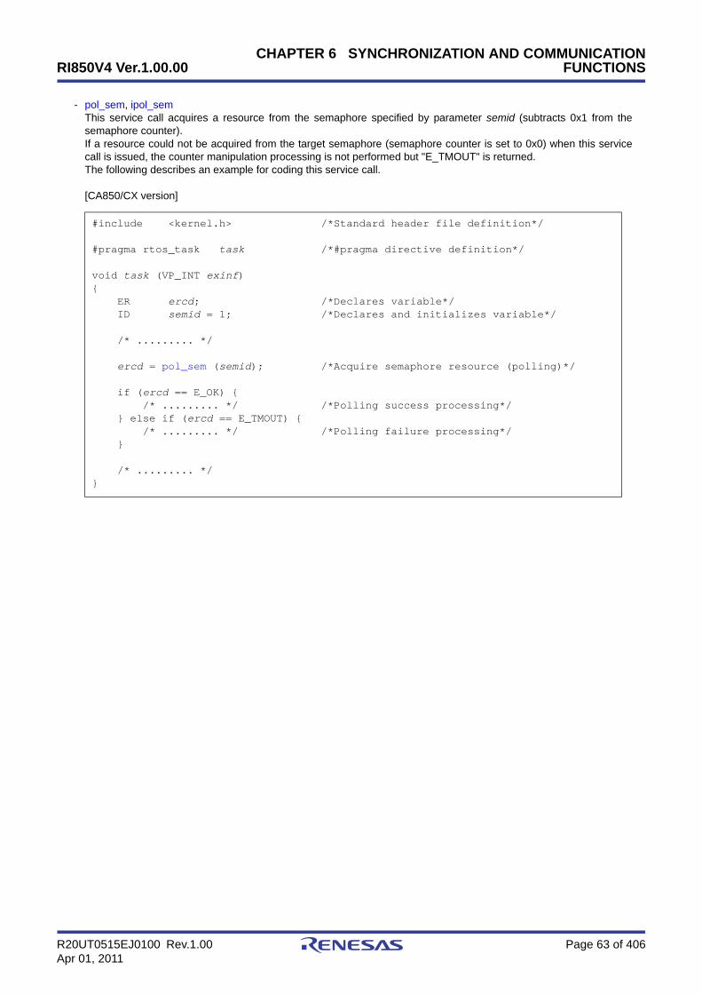
RI850V4 Ver.1.00.00
R20UT0515EJ0100 Rev.1.00 Page 63 of 406Apr 01, 2011
CHAPTER 6 SYNCHRONIZATION AND COMMUNICATIONFUNCTIONS
- pol_sem, ipol_semThis service call acquires a resource from the semaphore specified by parameter semid (subtracts 0x1 from thesemaphore counter).If a resource could not be acquired from the target semaphore (semaphore counter is set to 0x0) when this servicecall is issued, the counter manipulation processing is not performed but "E_TMOUT" is returned.The following describes an example for coding this service call.
[CA850/CX version]
#include <kernel.h> /*Standard header file definition*/
#pragma rtos_task task /*#pragma directive definition*/
void task (VP_INT exinf){ ER ercd; /*Declares variable*/ ID semid = 1; /*Declares and initializes variable*/
/* ......... */
ercd = pol_sem (semid); /*Acquire semaphore resource (polling)*/
if (ercd == E_OK) { /* ......... */ /*Polling success processing*/ } else if (ercd == E_TMOUT) { /* ......... */ /*Polling failure processing*/ }
/* ......... */}

RI850V4 Ver.1.00.00
R20UT0515EJ0100 Rev.1.00 Page 64 of 406Apr 01, 2011
CHAPTER 6 SYNCHRONIZATION AND COMMUNICATIONFUNCTIONS
- twai_semThis service call acquires a resource from the semaphore specified by parameter semid (subtracts 0x1 from thesemaphore counter).If no resources are acquired from the target semaphore when service call is issued this (no available resources exist),this service call does not acquire resources but queues the invoking task to the target semaphore wait queue andmoves it from the RUNNING state to the WAITING state with timeout (resource acquisition wait state).The WAITING state for a semaphore resource is cancelled in the following cases, and then moved to the READYstate.
The following describes an example for coding this service call.
[CA850/CX version]
Note 1 Invoking tasks are queued to the target semaphore wait queue in the order defined during configuration(FIFO order or priority order).
Note 2 TMO_FEVR is specified for wait time tmout, processing equivalent to wai_sem will be executed. WhenTMO_POL is specified, processing equivalent to pol_sem /ipol_sem will be executed.
WAITING State for a Semaphore Resource Cancel Operation Return Value
The resource was returned to the target semaphore as a result of issuing sig_sem. E_OK
The resource was returned to the target semaphore as a result of issuing isig_sem. E_OK
Forced release from waiting (accept rel_wai while waiting). E_RLWAI
Forced release from waiting (accept irel_wai while waiting). E_RLWAI
Polling failure or timeout. E_TMOUT
#include <kernel.h> /*Standard header file definition*/
#pragma rtos_task task /*#pragma directive definition*/
void task (VP_INT exinf){ ER ercd; /*Declares variable*/ ID semid = 1; /*Declares and initializes variable*/ TMO tmout = 3600; /*Declares and initializes variable*/
/* ......... */
ercd = twai_sem (semid, tmout); /*Acquire semaphore resource (with timeout)*/
if (ercd == E_OK) { /* ......... */ /*Normal termination processing*/ } else if (ercd == E_RLWAI) { /* ......... */ /*Forced termination processing*/ } else if (ercd == E_TMOUT) { /* ......... */ /*Timeout processing*/ }
/* ......... */}

RI850V4 Ver.1.00.00
R20UT0515EJ0100 Rev.1.00 Page 65 of 406Apr 01, 2011
CHAPTER 6 SYNCHRONIZATION AND COMMUNICATIONFUNCTIONS
6.2.3 Release semaphore resource
A resource is returned by issuing the following service call from the processing program.
- sig_sem, isig_semThese service calls return the resource to the semaphore specified by parameter semid (adds 0x1 to the semaphorecounter).If a task is queued in the wait queue of the target semaphore when this service call is issued, the countermanipulation processing is not performed but the resource is passed to the relevant task (first task of wait queue).As a result, the relevant task is unlinked from the wait queue and is moved from the WAITING state (WAITING statefor a semaphore resource) to the READY state, or from the WAITING-SUSPENDED state to the SUSPENDED state.The following describes an example for coding this service call.
[CA850/CX version]
Note With the RI850V4, the maximum possible number of semaphore resources (maximum resource count) isdefined during configuration. If the number of resources exceeds the specified maximum resource count,this service call therefore does not return the acquired resources (addition to the semaphore counter value)but returns E_QOVR.
#include <kernel.h> /*Standard header file definition*/
#pragma rtos_task task /*#pragma directive definition*/
void task (VP_INT exinf){ ID semid = 1; /*Declares and initializes variable*/
/* ......... */
sig_sem (semid); /*Release semaphore resource*/
/* ......... */}

RI850V4 Ver.1.00.00
R20UT0515EJ0100 Rev.1.00 Page 66 of 406Apr 01, 2011
CHAPTER 6 SYNCHRONIZATION AND COMMUNICATIONFUNCTIONS
6.2.4 Reference semaphore state
A semaphore status is referenced by issuing the following service call from the processing program.
- ref_sem, iref_semStores semaphore state packet (ID number of the task at the head of the wait queue, current resource count, etc.) ofthe semaphore specified by parameter semid in the area specified by parameter pk_rsem.The following describes an example for coding this service call.
[CA850/CX version]
Note For details about the semaphore state packet, refer to "16.2.4 Semaphore state packet".
#include <kernel.h> /*Standard header file definition*/
#pragma rtos_task task /*#pragma directive definition*/
void task (VP_INT exinf){ ID semid = 1; /*Declares and initializes variable*/ T_RSEM pk_rsem; /*Declares data structure*/ ID wtskid; /*Declares variable*/ UINT semcnt; /*Declares variable*/ ATR sematr; /*Declares variable*/ UINT maxsem; /*Declares variable*/
/* ......... */
ref_sem (semid, &pk_rsem); /*Reference semaphore state*/
wtskid = pk_rsem.wtskid; /*Reference ID number of the task at the */ /*head of the wait queue*/ semcnt = pk_rsem.semcnt; /*Reference current resource count*/ sematr = pk_rsem.sematr; /*Reference attribute*/ maxsem = pk_rsem.maxsem; /*Reference maximum resource count*/
/* ......... */}

RI850V4 Ver.1.00.00
R20UT0515EJ0100 Rev.1.00 Page 67 of 406Apr 01, 2011
CHAPTER 6 SYNCHRONIZATION AND COMMUNICATIONFUNCTIONS
6.3 Eventflags
The RI850V4 provides 32-bit eventflags as a queuing function for tasks, such as keeping the tasks waiting for execution,until the results of the execution of a given processing program are output.
The following shows a processing flow when using an eventflag.
Figure 6-2 Processing Flow (Eventflag)
6.3.1 Create eventflag
In the RI850V4, the method of creating an eventflag is limited to "static creation".Eventflags therefore cannot be created dynamically using a method such as issuing a service call from a processing
program.Static event flag creation means defining of event flags using static API "CRE_FLG" in the system configuration file.For details about the static API "CRE_FLG", refer to "18.5.4 Eventflag information".
Wait for eventflag
Set eventflag
Task APriority: High
Task BPriority: Low
Queuing period

RI850V4 Ver.1.00.00
R20UT0515EJ0100 Rev.1.00 Page 68 of 406Apr 01, 2011
CHAPTER 6 SYNCHRONIZATION AND COMMUNICATIONFUNCTIONS
6.3.2 Set eventflag
bit pattern is set by issuing the following service call from the processing program.
- set_flg, iset_flgThese service calls set the result of ORing the bit pattern of the eventflag specified by parameter flgid and the bitpattern specified by parameter setptn as the bit pattern of the target eventflag.If the required condition of the task queued to the target eventflag wait queue is satisfied when this service call isissued, the relevant task is unlinked from the wait queue at the same time as bit pattern setting processing.As a result, the relevant task is moved from the WAITING state (WAITING state for an eventflag) to the READY state,or from the WAITING-SUSPENDED state to the SUSPENDED state.The following describes an example for coding this service call.
[CA850/CX version]
Note If the bit pattern set to the target eventflag is B'1100 and the bit pattern specified by parameter setptn isB'1010 when this service call is issued, the bit pattern of the target eventflag is set to B'1110.
#include <kernel.h> /*Standard header file definition*/
#pragma rtos_task task /*#pragma directive definition*/
void task (VP_INT exinf){ ID flgid = 1; /*Declares and initializes variable*/ FLGPTN setptn = 10; /*Declares and initializes variable*/
/* ......... */
set_flg (flgid, setptn); /*Set eventflag*/
/* ......... */}
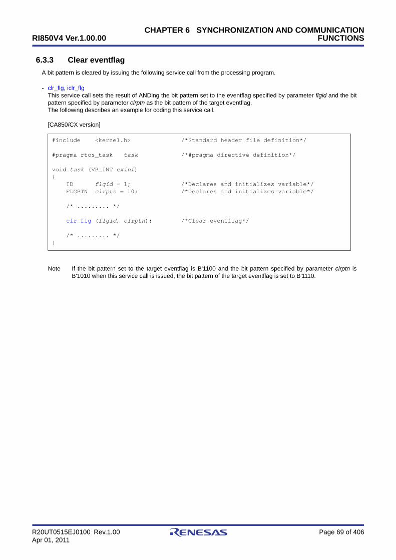
RI850V4 Ver.1.00.00
R20UT0515EJ0100 Rev.1.00 Page 69 of 406Apr 01, 2011
CHAPTER 6 SYNCHRONIZATION AND COMMUNICATIONFUNCTIONS
6.3.3 Clear eventflag
A bit pattern is cleared by issuing the following service call from the processing program.
- clr_flg, iclr_flgThis service call sets the result of ANDing the bit pattern set to the eventflag specified by parameter flgid and the bitpattern specified by parameter clrptn as the bit pattern of the target eventflag.The following describes an example for coding this service call.
[CA850/CX version]
Note If the bit pattern set to the target eventflag is B'1100 and the bit pattern specified by parameter clrptn isB'1010 when this service call is issued, the bit pattern of the target eventflag is set to B'1110.
#include <kernel.h> /*Standard header file definition*/
#pragma rtos_task task /*#pragma directive definition*/
void task (VP_INT exinf){ ID flgid = 1; /*Declares and initializes variable*/ FLGPTN clrptn = 10; /*Declares and initializes variable*/
/* ......... */
clr_flg (flgid, clrptn); /*Clear eventflag*/
/* ......... */}
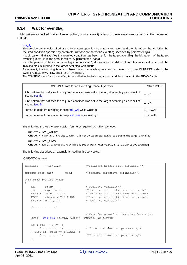
RI850V4 Ver.1.00.00
R20UT0515EJ0100 Rev.1.00 Page 70 of 406Apr 01, 2011
CHAPTER 6 SYNCHRONIZATION AND COMMUNICATIONFUNCTIONS
6.3.4 Wait for eventflag
A bit pattern is checked (waiting forever, polling, or with timeout) by issuing the following service call from the processingprogram.
- wai_flgThis service call checks whether the bit pattern specified by parameter waiptn and the bit pattern that satisfies therequired condition specified by parameter wfmode are set to the eventflag specified by parameter flgid.If a bit pattern that satisfies the required condition has been set for the target eventflag, the bit pattern of the targeteventflag is stored in the area specified by parameter p_flgptn.If the bit pattern of the target eventflag does not satisfy the required condition when this service call is issued, theinvoking task is queued to the target eventflag wait queue.As a result, the invoking task is unlinked from the ready queue and is moved from the RUNNING state to theWAITING state (WAITING state for an eventflag).The WAITING state for an eventflag is cancelled in the following cases, and then moved to the READY state.
The following shows the specification format of required condition wfmode.
- wfmode = TWF_ANDWChecks whether all of the bits to which 1 is set by parameter waiptn are set as the target eventflag.
- wfmode = TWF_ORWChecks which bit, among bits to which 1 is set by parameter waiptn, is set as the target eventflag.
The following describes an example for coding this service call.
[CA850/CX version]
WAITING State for an Eventflag Cancel Operation Return Value
A bit pattern that satisfies the required condition was set to the target eventflag as a result ofissuing set_flg. E_OK
A bit pattern that satisfies the required condition was set to the target eventflag as a result ofissuing iset_flg. E_OK
Forced release from waiting (accept rel_wai while waiting). E_RLWAI
Forced release from waiting (accept irel_wai while waiting). E_RLWAI
#include <kernel.h> /*Standard header file definition*/
#pragma rtos_task task /*#pragma directive definition*/
void task (VP_INT exinf){ ER ercd; /*Declares variable*/ ID flgid = 1; /*Declares and initializes variable*/ FLGPTN waiptn = 14; /*Declares and initializes variable*/ MODE wfmode = TWF_ANDW; /*Declares and initializes variable*/ FLGPTN p_flgptn; /*Declares variable*/
/* ......... */
/*Wait for eventflag (waiting forever)*/ ercd = wai_flg (flgid, waiptn, wfmode, &p_flgptn);
if (ercd == E_OK) { /* ......... */ /*Normal termination processing*/ } else if (ercd == E_RLWAI) { /* ......... */ /*Forced termination processing*/ }

RI850V4 Ver.1.00.00
R20UT0515EJ0100 Rev.1.00 Page 71 of 406Apr 01, 2011
CHAPTER 6 SYNCHRONIZATION AND COMMUNICATIONFUNCTIONS
Note 1 With the RI850V4, whether to enable queuing of multiple tasks to the event flag wait queue is defined duringconfiguration. If this service call is issued for the event flag (TW_WSGL attribute) to which a wait task isqueued, therefore, "E_ILUSE" is returned regardless of whether the required condition is immediatelysatisfied.
TA_WSGL: Only one task is allowed to be in the WAITING state for the eventflag.TA_WMUL: Multiple tasks are allowed to be in the WAITING state for the eventflag.
Note 2 Invoking tasks are queued to the target event flag (TA_WMUL attribute) wait queue in the order definedduring configuration (FIFO order or priority order).
Note 3 The RI850V4 performs bit pattern clear processing (0x0 setting) when the required condition of the targeteventflag (TA_CLR attribute) is satisfied.
Note 4 If the WAITING state for an eventflag is forcibly released by issuing rel_wai or irel_wai, the contents of thearea specified by parameter p_flgptn will be undefined.
/* ......... */}

RI850V4 Ver.1.00.00
R20UT0515EJ0100 Rev.1.00 Page 72 of 406Apr 01, 2011
CHAPTER 6 SYNCHRONIZATION AND COMMUNICATIONFUNCTIONS
- pol_flg, ipol_flgThis service call checks whether the bit pattern specified by parameter waiptn and the bit pattern that satisfies therequired condition specified by parameter wfmode are set to the eventflag specified by parameter flgid.If the bit pattern that satisfies the required condition has been set to the target eventflag, the bit pattern of the targeteventflag is stored in the area specified by parameter p_flgptn.If the bit pattern of the target eventflag does not satisfy the required condition when this service call is issued,"E_TMOUT" is returned.The following shows the specification format of required condition wfmode.
- wfmode = TWF_ANDWChecks whether all of the bits to which 1 is set by parameter waiptn are set as the target eventflag.
- wfmode = TWF_ORWChecks which bit, among bits to which 1 is set by parameter waiptn, is set as the target eventflag.
The following describes an example for coding this service call.
[CA850/CX version]
Note 1 With the RI850V4, whether to enable queuing of multiple tasks to the event flag wait queue is defined duringconfiguration. If this service call is issued for the event flag (TW_WSGL attribute) to which a wait task isqueued, therefore, "E_ILUSE" is returned regardless of whether the required condition is immediatelysatisfied.
TA_WSGL: Only one task is allowed to be in the WAITING state for the eventflag.TA_WMUL: Multiple tasks are allowed to be in the WAITING state for the eventflag.
Note 2 The RI850V4 performs bit pattern clear processing (0x0 setting) when the required condition of the targeteventflag (TA_CLR attribute) is satisfied.
Note 3 If the bit pattern of the target event flag does not satisfy the required condition when this service call isissued, the contents in the area specified by parameter p_flgptn become undefined.
#include <kernel.h> /*Standard header file definition*/
#pragma rtos_task task /*#pragma directive definition*/
void task (VP_INT exinf){ ER ercd; /*Declares variable*/ ID flgid = 1; /*Declares and initializes variable*/ FLGPTN waiptn = 14; /*Declares and initializes variable*/ MODE wfmode = TWF_ANDW; /*Declares and initializes variable*/ FLGPTN p_flgptn; /*Declares variable*/
/* ......... */
/*Wait for eventflag (polling)*/ ercd = pol_flg (flgid, waiptn, wfmode, &p_flgptn);
if (ercd == E_OK) { /* ......... */ /*Polling success processing*/ } else if (ercd == E_TMOUT) { /* ......... */ /*Polling failure processing*/ }
/* ......... */}

RI850V4 Ver.1.00.00
R20UT0515EJ0100 Rev.1.00 Page 73 of 406Apr 01, 2011
CHAPTER 6 SYNCHRONIZATION AND COMMUNICATIONFUNCTIONS
- twai_flgThis service call checks whether the bit pattern specified by parameter waiptn and the bit pattern that satisfies therequired condition specified by parameter wfmode are set to the eventflag specified by parameter flgid.If a bit pattern that satisfies the required condition has been set for the target eventflag, the bit pattern of the targeteventflag is stored in the area specified by parameter p_flgptn.If the bit pattern of the target eventflag does not satisfy the required condition when this service call is issued, theinvoking task is queued to the target eventflag wait queue.As a result, the invoking task is unlinked from the ready queue and is moved from the RUNNING state to theWAITING state (WAITING state for an eventflag).The WAITING state for an eventflag is cancelled in the following cases, and then moved to the READY state.
The following shows the specification format of required condition wfmode.
- wfmode = TWF_ANDWChecks whether all of the bits to which 1 is set by parameter waiptn are set as the target eventflag.
- wfmode = TWF_ORWChecks which bit, among bits to which 1 is set by parameter waiptn, is set as the target eventflag.
The following describes an example for coding this service call.
[CA850/CX version]
WAITING State for an Eventflag Cancel Operation Return Value
A bit pattern that satisfies the required condition was set to the target eventflag as a result ofissuing set_flg. E_OK
A bit pattern that satisfies the required condition was set to the target eventflag as a result ofissuing iset_flg. E_OK
Forced release from waiting (accept rel_wai while waiting). E_RLWAI
Forced release from waiting (accept irel_wai while waiting). E_RLWAI
Polling failure or timeout. E_TMOUT
#include <kernel.h> /*Standard header file definition*/
#pragma rtos_task task /*#pragma directive definition*/
void task (VP_INT exinf){ ER ercd; /*Declares variable*/ ID flgid = 1; /*Declares and initializes variable*/ FLGPTN waiptn = 14; /*Declares and initializes variable*/ MODE wfmode = TWF_ANDW; /*Declares and initializes variable*/ FLGPTN p_flgptn; /*Declares variable*/ TMO tmout = 3600; /*Declares and initializes variable*/
/* ......... */
/*Wait for eventflag (with timeout)*/ ercd = twai_flg (flgid, waiptn, wfmode, &p_flgptn, tmout);
if (ercd == E_OK) { /* ......... */ /*Normal termination processing*/ } else if (ercd == E_RLWAI) { /* ......... */ /*Forced termination processing*/ } else if (ercd == E_TMOUT) { /* ......... */ /*Timeout processing*/ }

RI850V4 Ver.1.00.00
R20UT0515EJ0100 Rev.1.00 Page 74 of 406Apr 01, 2011
CHAPTER 6 SYNCHRONIZATION AND COMMUNICATIONFUNCTIONS
Note 1 With the RI850V4, whether to enable queuing of multiple tasks to the event flag wait queue is defined duringconfiguration. If this service call is issued for the event flag (TW_WSGL attribute) to which a wait task isqueued, therefore, "E_ILUSE" is returned regardless of whether the required condition is immediatelysatisfied.
TA_WSGL: Only one task is allowed to be in the WAITING state for the eventflag.TA_WMUL: Multiple tasks are allowed to be in the WAITING state for the eventflag.
Note 2 Invoking tasks are queued to the target event flag (TA_WMUL attribute) wait queue in the order definedduring configuration (FIFO order or priority order).
Note 3 The RI850V4 performs bit pattern clear processing (0x0 setting) when the required condition of the targeteventflag (TA_CLR attribute) is satisfied.
Note 4 If the event flag wait state is cancelled because rel_wai or irel_wai was issued or the wait time elapsed, thecontents in the area specified by parameter p_flgptn become undefined.
Note 5 TMO_FEVR is specified for wait time tmout, processing equivalent to wai_flg will be executed. WhenTMO_POL is specified, processing equivalent to pol_flg /ipol_flg will be executed.
/* ......... */}

RI850V4 Ver.1.00.00
R20UT0515EJ0100 Rev.1.00 Page 75 of 406Apr 01, 2011
CHAPTER 6 SYNCHRONIZATION AND COMMUNICATIONFUNCTIONS
6.3.5 Reference eventflag state
An eventflag status is referenced by issuing the following service call from the processing program.
- ref_flg, iref_flgStores eventflag state packet (ID number of the task at the head of the wait queue, current bit pattern, etc.) of theeventflag specified by parameter flgid in the area specified by parameter pk_rflg.The following describes an example for coding this service call.
[CA850/CX version]
Note For details about the eventflag state packet, refer to "16.2.5 Eventflag state packet".
#include <kernel.h> /*Standard header file definition*/
#pragma rtos_task task /*#pragma directive definition*/
void task (VP_INT exinf){ ID flgid = 1; /*Declares and initializes variable*/ T_RFLG pk_rflg; /*Declares data structure*/ ID wtskid; /*Declares variable*/ FLGPTN flgptn; /*Declares variable*/ ATR flgatr; /*Declares variable*/
/* ......... */
ref_flg (flgid, &pk_rflg); /*Reference eventflag state*/
wtskid = pk_rflg.wtskid; /*Reference ID number of the task at the */ /*head of the wait queue*/ flgptn = pk_rflg.flgptn; /*Reference current bit pattern*/ flgatr = pk_rflg.flgatr; /*Reference attribute*/
/* ......... */}

RI850V4 Ver.1.00.00
R20UT0515EJ0100 Rev.1.00 Page 76 of 406Apr 01, 2011
CHAPTER 6 SYNCHRONIZATION AND COMMUNICATIONFUNCTIONS
6.4 Data Queues
Multitask processing requires the inter-task communication function (data transfer function) that reports the processingresult of a task to another task. The RI850V4 therefore provides the data queues that have the data queue area in whichdata read/write is enabled for transferring the prescribed size of data.
The following shows a processing flow when using a data queue.
Figure 6-3 Processing Flow (Data Queue)
Note Data units of 4 bytes are transmitted or received at a time.
6.4.1 Create data queue
In the RI850V4, the method of creating a deta queue is limited to "static creation".Data queues therefore cannot be created dynamically using a method such as issuing a service call from a processing
program.Static data queue creation means defining of data queues using static API "CRE_DTQ" in the system configuration file.For details about the static API "CRE_DTQ", refer to "18.5.5 Data queue information".
Task APriority: High
Task BPriority: Low
Reception wait period
Receive from data queue
Send to data queue

RI850V4 Ver.1.00.00
R20UT0515EJ0100 Rev.1.00 Page 77 of 406Apr 01, 2011
CHAPTER 6 SYNCHRONIZATION AND COMMUNICATIONFUNCTIONS
6.4.2 Send to data queue
A data is transmitted by issuing the following service call from the processing program.
- snd_dtqThis service call writes data specified by parameter data to the data queue area of the data queue specified byparameter dtqid.If there is no available space for writing data in the data queue area of the target data queue when this service call isissued, this service call does not write data but queues the invoking task to the transmission wait queue of the targetdata queue and moves it from the RUNNING state to the WAITING state (data transmission wait state).The sending WAITING state for a data queue is cancelled in the following cases, and then moved to the READYstate.
If a task has been queued to the reception wait queue of the target data queue when this service call is issued, thisservice call does not write data but transfers the data to the task. As a result, the task is unlinked from the receptionwait queue and moves from the WAITING state (data reception wait state) to the READY state, or from the WAITING-SUSPENDED state to the SUSPENDED state.The following describes an example for coding this service call.
[CA850/CX version]
Sending WAITING State for a Data Queue Cancel Operation Return Value
Available space was secured in the data queue area of the target data queue as a result ofissuing rcv_dtq. E_OK
Available space was secured in the data queue area of the target data queue as a result ofissuing prcv_dtq. E_OK
Available space was secured in the data queue area of the target data queue as a result ofissuing iprcv_dtq. E_OK
Available space was secured in the data queue area of the target data queue as a result ofissuing trcv_dtq. E_OK
Forced release from waiting (accept rel_wai while waiting). E_RLWAI
Forced release from waiting (accept irel_wai while waiting). E_RLWAI
#include <kernel.h> /*Standard header file definition*/
#pragma rtos_task task /*#pragma directive definition*/
void task (VP_INT exinf){ ER ercd; /*Declares variable*/ ID dtqid = 1; /*Declares and initializes variable*/ VP_INT data = 123; /*Declares and initializes variable*/
/* ......... */
ercd = snd_dtq (dtqid, data); /*Send to data queue (waiting forever)*/
if (ercd == E_OK) { /* ......... */ /*Normal termination processing*/ } else if (ercd == E_RLWAI) { /* ......... */ /*Forced termination processing*/ }
/* ......... */}
RI850V4 Ver.1.00.00
R20UT0515EJ0100 Rev.1.00 Page 78 of 406Apr 01, 2011
CHAPTER 6 SYNCHRONIZATION AND COMMUNICATIONFUNCTIONS
Note 1 Data is written to the data queue area of the target data queue in the order of the data transmission request.
Note 2 Invoking tasks are queued to the transmission wait queue of the target data queue in the order definedduring configuration (FIFO order or priority order).

RI850V4 Ver.1.00.00
R20UT0515EJ0100 Rev.1.00 Page 79 of 406Apr 01, 2011
CHAPTER 6 SYNCHRONIZATION AND COMMUNICATIONFUNCTIONS
- psnd_dtq, ipsnd_dtqThese service calls write data specified by parameter data to the data queue area of the data queue specified byparameter dtqid.If there is no available space for writing data in the data queue area of the target data queue when either of theseservice calls is issued, data is not written but E_TMOUT is returned.If a task has been queued to the reception wait queue of the target data queue when this service call is issued, thisservice call does not write data but transfers the data to the task. As a result, the task is unlinked from the receptionwait queue and moves from the WAITING state (data reception wait state) to the READY state, or from the WAITING-SUSPENDED state to the SUSPENDED state.The following describes an example for coding this service call.
[CA850/CX version]
Note Data is written to the data queue area of the target data queue in the order of the data transmission request.
#include <kernel.h> /*Standard header file definition*/
#pragma rtos_task task /*#pragma directive definition*/
void task (VP_INT exinf){ ER ercd; /*Declares variable*/ ID dtqid = 1; /*Declares and initializes variable*/ VP_INT data = 123; /*Declares and initializes variable*/
/* ......... */
/*Send to data queue (polling)*/ ercd = psnd_dtq (dtqid, data);
if (ercd == E_OK) { /* ......... */ /*Polling success processing*/ } else if (ercd == E_TMOUT) { /* ......... */ /*Polling failure processing*/ }
/* ......... */}
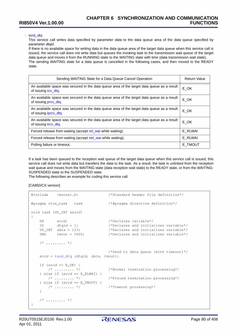
RI850V4 Ver.1.00.00
R20UT0515EJ0100 Rev.1.00 Page 80 of 406Apr 01, 2011
CHAPTER 6 SYNCHRONIZATION AND COMMUNICATIONFUNCTIONS
- tsnd_dtqThis service call writes data specified by parameter data to the data queue area of the data queue specified byparameter dtqid.If there is no available space for writing data in the data queue area of the target data queue when this service call isissued, the service call does not write data but queues the invoking task to the transmission wait queue of the targetdata queue and moves it from the RUNNING state to the WAITING state with time (data transmission wait state).The sending WAITING state for a data queue is cancelled in the following cases, and then moved to the READYstate.
If a task has been queued to the reception wait queue of the target data queue when this service call is issued, thisservice call does not write data but transfers the data to the task. As a result, the task is unlinked from the receptionwait queue and moves from the WAITING state (data reception wait state) to the READY state, or from the WAITING-SUSPENDED state to the SUSPENDED state.The following describes an example for coding this service call.
[CA850/CX version]
Sending WAITING State for a Data Queue Cancel Operation Return Value
An available space was secured in the data queue area of the target data queue as a resultof issuing rcv_dtq. E_OK
An available space was secured in the data queue area of the target data queue as a resultof issuing prcv_dtq. E_OK
An available space was secured in the data queue area of the target data queue as a resultof issuing iprcv_dtq. E_OK
An available space was secured in the data queue area of the target data queue as a resultof issuing trcv_dtq. E_OK
Forced release from waiting (accept rel_wai while waiting). E_RLWAI
Forced release from waiting (accept irel_wai while waiting). E_RLWAI
Polling failure or timeout. E_TMOUT
#include <kernel.h> /*Standard header file definition*/
#pragma rtos_task task /*#pragma directive definition*/
void task (VP_INT exinf){ ER ercd; /*Declares variable*/ ID dtqid = 1; /*Declares and initializes variable*/ VP_INT data = 123; /*Declares and initializes variable*/ TMO tmout = 3600; /*Declares and initializes variable*/
/* ......... */
/*Send to data queue (with timeout)*/ ercd = tsnd_dtq (dtqid, data, tmout);
if (ercd == E_OK) { /* ......... */ /*Normal termination processing*/ } else if (ercd == E_RLWAI) { /* ......... */ /*Forced termination processing*/ } else if (ercd == E_TMOUT) { /* ......... */ /*Timeout processing*/ }
/* ......... */}
RI850V4 Ver.1.00.00
R20UT0515EJ0100 Rev.1.00 Page 81 of 406Apr 01, 2011
CHAPTER 6 SYNCHRONIZATION AND COMMUNICATIONFUNCTIONS
Note 1 Data is written to the data queue area of the target data queue in the order of the data transmission request.
Note 2 Invoking tasks are queued to the transmission wait queue of the target data queue in the order definedduring configuration (FIFO order or priority order).
Note 3 TMO_FEVR is specified for wait time tmout, processing equivalent to snd_dtq will be executed. WhenTMO_POL is specified, processing equivalent to psnd_dtq /ipsnd_dtq will be executed.

RI850V4 Ver.1.00.00
R20UT0515EJ0100 Rev.1.00 Page 82 of 406Apr 01, 2011
CHAPTER 6 SYNCHRONIZATION AND COMMUNICATIONFUNCTIONS
6.4.3 Forced send to data queue
Data is forcibly transmitted by issuing the following service call from the processing program.
- fsnd_dtq, ifsnd_dtqThese service calls write data specified by parameter data to the data queue area of the data queue specified byparameter dtqid.If there is no available space for writing data in the data queue area of the target data queue when either of theseservice calls is issued, the service call overwrites data to the area with the oldest data that was written.If a task has been queued to the reception wait queue of the target data queue when this service call is issued, thisservice call does not write data but transfers the data to the task. As a result, the task is unlinked from the receptionwait queue and moves from the WAITING state (data reception wait state) to the READY state, or from the WAITING-SUSPENDED state to the SUSPENDED state.The following describes an example for coding this service call.
[CA850/CX version]
#include <kernel.h> /*Standard header file definition*/
#pragma rtos_task task /*#pragma directive definition*/
void task (VP_INT exinf){ ID dtqid = 1; /*Declares and initializes variable*/ VP_INT data = 123; /*Declares and initializes variable*/
/* ......... */
fsnd_dtq (dtqid, data); /*Forced send to data queue*/
/* ......... */}
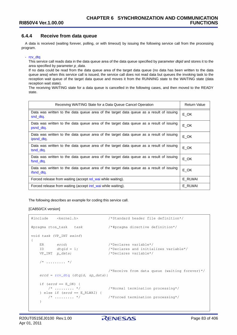
RI850V4 Ver.1.00.00
R20UT0515EJ0100 Rev.1.00 Page 83 of 406Apr 01, 2011
CHAPTER 6 SYNCHRONIZATION AND COMMUNICATIONFUNCTIONS
6.4.4 Receive from data queue
A data is received (waiting forever, polling, or with timeout) by issuing the following service call from the processingprogram.
- rcv_dtqThis service call reads data in the data queue area of the data queue specified by parameter dtqid and stores it to thearea specified by parameter p_data.If no data could be read from the data queue area of the target data queue (no data has been written to the dataqueue area) when this service call is issued, the service call does not read data but queues the invoking task to thereception wait queue of the target data queue and moves it from the RUNNING state to the WAITING state (datareception wait state).The receiving WAITING state for a data queue is cancelled in the following cases, and then moved to the READYstate.
The following describes an example for coding this service call.
[CA850/CX version]
Receiving WAITING State for a Data Queue Cancel Operation Return Value
Data was written to the data queue area of the target data queue as a result of issuingsnd_dtq. E_OK
Data was written to the data queue area of the target data queue as a result of issuingpsnd_dtq. E_OK
Data was written to the data queue area of the target data queue as a result of issuingipsnd_dtq. E_OK
Data was written to the data queue area of the target data queue as a result of issuingtsnd_dtq. E_OK
Data was written to the data queue area of the target data queue as a result of issuingfsnd_dtq. E_OK
Data was written to the data queue area of the target data queue as a result of issuingifsnd_dtq. E_OK
Forced release from waiting (accept rel_wai while waiting). E_RLWAI
Forced release from waiting (accept irel_wai while waiting). E_RLWAI
#include <kernel.h> /*Standard header file definition*/
#pragma rtos_task task /*#pragma directive definition*/
void task (VP_INT exinf){ ER ercd; /*Declares variable*/ ID dtqid = 1; /*Declares and initializes variable*/ VP_INT p_data; /*Declares variable*/
/* ......... */
/*Receive from data queue (waiting forever)*/ ercd = rcv_dtq (dtqid, &p_data);
if (ercd == E_OK) { /* ......... */ /*Normal termination processing*/ } else if (ercd == E_RLWAI) { /* ......... */ /*Forced termination processing*/ }
RI850V4 Ver.1.00.00
R20UT0515EJ0100 Rev.1.00 Page 84 of 406Apr 01, 2011
CHAPTER 6 SYNCHRONIZATION AND COMMUNICATIONFUNCTIONS
Note 1 Invoking tasks are queued to the reception wait queue of the target data queue in the order of the datareception request.
Note 2 If the receiving WAITING state for a data queue is forcibly released by issuing rel_wai or irel_wai, thecontents of the area specified by parameter p_data will be undefined.
/* ......... */}

RI850V4 Ver.1.00.00
R20UT0515EJ0100 Rev.1.00 Page 85 of 406Apr 01, 2011
CHAPTER 6 SYNCHRONIZATION AND COMMUNICATIONFUNCTIONS
- prcv_dtq, iprcv_dtqThese service calls read data in the data queue area of the data queue specified by parameter dtqid and stores it tothe area specified by parameter p_data.If no data could be read from the data queue area of the target data queue (no data has been written to the dataqueue area) when either of these service calls is issued, the service call does not read data but E_TMOUT isreturned.The following describes an example for coding this service call.
[CA850/CX version]
Note If no data could be read from the data queue area of the target data queue (no data has been written to thedata queue area) when either of these service calls is issued, the contents in the area specified byparameter p_data become undefined.
#include <kernel.h> /*Standard header file definition*/
#pragma rtos_task task /*#pragma directive definition*/
void task (VP_INT exinf){ ER ercd; /*Declares variable*/ ID dtqid = 1; /*Declares and initializes variable*/ VP_INT p_data; /*Declares variable*/
/* ......... */
/*Receive from data queue (polling)*/ ercd = prcv_dtq (dtqid, &p_data);
if (ercd == E_OK) { /* ......... */ /*Polling success processing*/ } else if (ercd == E_TMOUT) { /* ......... */ /*Polling failure processing*/ }
/* ......... */}

RI850V4 Ver.1.00.00
R20UT0515EJ0100 Rev.1.00 Page 86 of 406Apr 01, 2011
CHAPTER 6 SYNCHRONIZATION AND COMMUNICATIONFUNCTIONS
- trcv_dtqThis service call reads data in the data queue area of the data queue specified by parameter dtqid and stores it to thearea specified by parameter p_data.If no data could be read from the data queue area of the target data queue (no data has been written to the dataqueue area) when this service call is issued, the service call does not read data but queues the invoking task to thereception wait queue of the target data queue and moves it from the RUNNING state to the WAITING state with timeout (data reception wait state).The receiving WAITING state for a data queue is cancelled in the following cases, and then moved to the READYstate.
The following describes an example for coding this service call.
[CA850/CX version]
Receiving WAITING State for a Data Queue Cancel Operation Return Value
Data was written to the data queue area of the target data queue as a result of issuingsnd_dtq. E_OK
Data was written to the data queue area of the target data queue as a result of issuingpsnd_dtq. E_OK
Data was written to the data queue area of the target data queue as a result of issuingipsnd_dtq. E_OK
Data was written to the data queue area of the target data queue as a result of issuingtsnd_dtq. E_OK
Data was written to the data queue area of the target data queue as a result of issuingfsnd_dtq. E_OK
Data was written to the data queue area of the target data queue as a result of issuingifsnd_dtq. E_OK
Forced release from waiting (accept rel_wai while waiting). E_RLWAI
Forced release from waiting (accept irel_wai while waiting). E_RLWAI
Polling failure or timeout. E_TMOUT
#include <kernel.h> /*Standard header file definition*/
#pragma rtos_task task /*#pragma directive definition*/
void task (VP_INT exinf){ ER ercd; /*Declares variable*/ ID dtqid = 1; /*Declares and initializes variable*/ VP_INT p_data; /*Declares variable*/ TMO tmout = 3600; /*Declares and initializes variable*/
/* ......... */
/*Receive from data queue (with timeout)*/ ercd = trcv_dtq (dtqid, &p_data, tmout);
if (ercd == E_OK) { /* ......... */ /*Normal termination processing*/ } else if (ercd == E_RLWAI) { /* ......... */ /*Forced termination processing*/ } else if (ercd == E_TMOUT) { /* ......... */ /*Timeout processing*/ }

RI850V4 Ver.1.00.00
R20UT0515EJ0100 Rev.1.00 Page 87 of 406Apr 01, 2011
CHAPTER 6 SYNCHRONIZATION AND COMMUNICATIONFUNCTIONS
Note 1 Invoking tasks are queued to the reception wait queue of the target data queue in the order of the datareception request.
Note 2 If the data reception wait state is cancelled because rel_wai or irel_wai was issued or the wait time elapsed,the contents in the area specified by parameter p_data become undefined.
Note 3 TMO_FEVR is specified for wait time tmout, processing equivalent to rcv_dtq will be executed. WhenTMO_POL is specified, processing equivalent to prcv_dtq /iprcv_dtq will be executed.
/* ......... */}

RI850V4 Ver.1.00.00
R20UT0515EJ0100 Rev.1.00 Page 88 of 406Apr 01, 2011
CHAPTER 6 SYNCHRONIZATION AND COMMUNICATIONFUNCTIONS
6.4.5 Reference data queue state
A data queue status is referenced by issuing the following service call from the processing program.
- ref_dtq, iref_dtqThese service calls store the detailed information of the data queue (existence of waiting tasks, number of dataelements in the data queue, etc.) specified by parameter dtqid into the area specified by parameter pk_rdtq.The following describes an example for coding this service call.
[CA850/CX version]
Note For details about the data queue state packet, refer to "16.2.6 Data queue state packet".
#include <kernel.h> /*Standard header file definition*/
#pragma rtos_task task /*#pragma directive definition*/
void task (VP_INT exinf){ ID dtqid = 1; /*Declares and initializes variable*/ T_RDTQ pk_rdtq; /*Declares data structure*/ ID stskid; /*Declares variable*/ ID rtskid; /*Declares variable*/ UINT sdtqcnt; /*Declares variable*/ ATR dtqatr; /*Declares variable*/ UINT dtqcnt; /*Declares variable*/
/* ......... */
ref_dtq (dtqid, &pk_rdtq); /*Reference data queue state*/
stskid = pk_rdtq.stskid; /*Acquires existence of tasks waiting for */ /*data transmission*/ rtskid = pk_rdtq.rtskid; /*Acquires existence of tasks waiting for */ /*data reception*/ sdtqcnt = pk_rdtq.sdtqcnt; /*Reference the number of data elements in */ /*data queue*/ dtqatr = pk_rdtq.dtqatr; /*Reference attribute*/ dtqcnt = pk_rdtq.dtqcnt; /*Referene data count*/
/* ......... */}
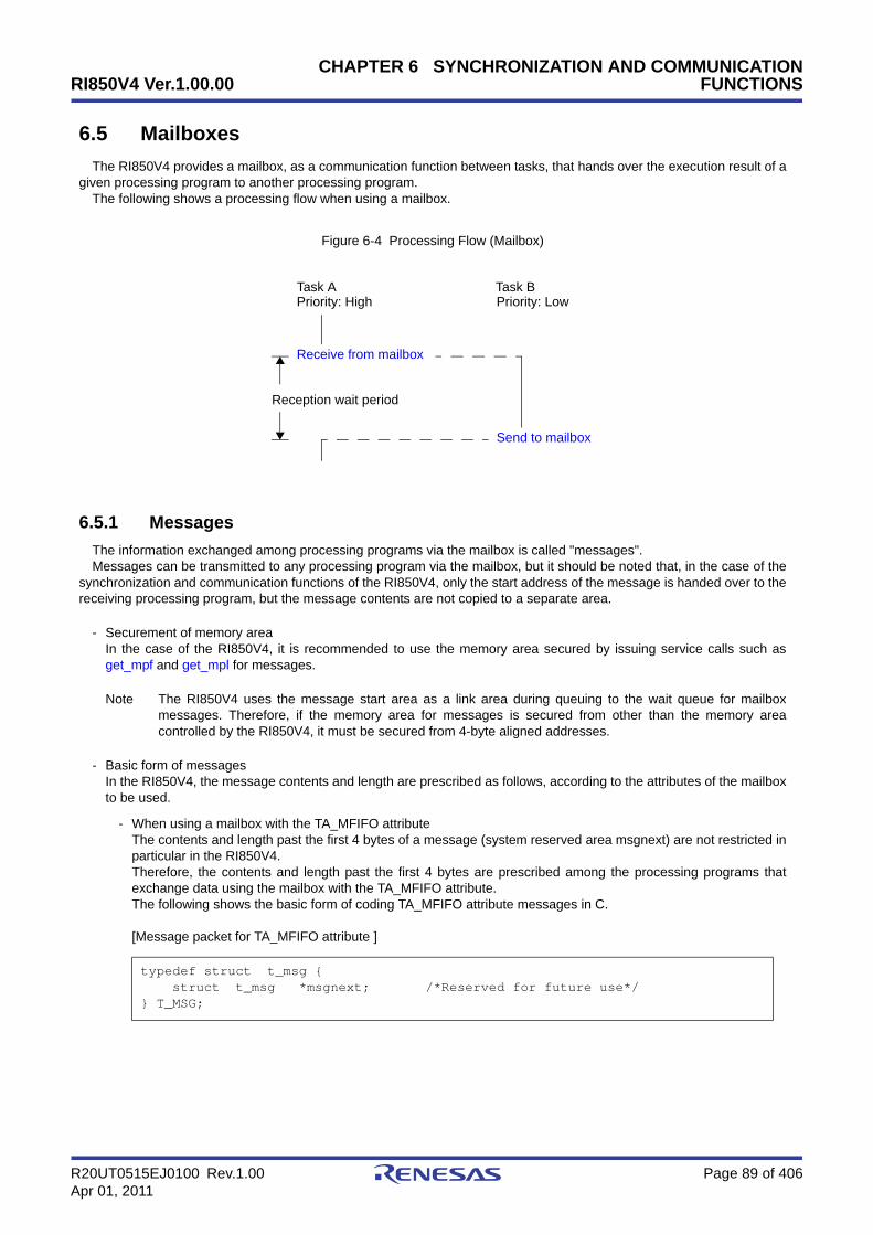
RI850V4 Ver.1.00.00
R20UT0515EJ0100 Rev.1.00 Page 89 of 406Apr 01, 2011
CHAPTER 6 SYNCHRONIZATION AND COMMUNICATIONFUNCTIONS
6.5 Mailboxes
The RI850V4 provides a mailbox, as a communication function between tasks, that hands over the execution result of agiven processing program to another processing program.
The following shows a processing flow when using a mailbox.
Figure 6-4 Processing Flow (Mailbox)
6.5.1 Messages
The information exchanged among processing programs via the mailbox is called "messages".Messages can be transmitted to any processing program via the mailbox, but it should be noted that, in the case of the
synchronization and communication functions of the RI850V4, only the start address of the message is handed over to thereceiving processing program, but the message contents are not copied to a separate area.
- Securement of memory areaIn the case of the RI850V4, it is recommended to use the memory area secured by issuing service calls such asget_mpf and get_mpl for messages.
Note The RI850V4 uses the message start area as a link area during queuing to the wait queue for mailboxmessages. Therefore, if the memory area for messages is secured from other than the memory areacontrolled by the RI850V4, it must be secured from 4-byte aligned addresses.
- Basic form of messagesIn the RI850V4, the message contents and length are prescribed as follows, according to the attributes of the mailboxto be used.
- When using a mailbox with the TA_MFIFO attributeThe contents and length past the first 4 bytes of a message (system reserved area msgnext) are not restricted inparticular in the RI850V4.Therefore, the contents and length past the first 4 bytes are prescribed among the processing programs thatexchange data using the mailbox with the TA_MFIFO attribute.The following shows the basic form of coding TA_MFIFO attribute messages in C.
[Message packet for TA_MFIFO attribute ]
typedef struct t_msg { struct t_msg *msgnext; /*Reserved for future use*/} T_MSG;
Receive from mailbox
Send to mailbox
Reception wait period
Task APriority: High Priority: Low
Task B

RI850V4 Ver.1.00.00
R20UT0515EJ0100 Rev.1.00 Page 90 of 406Apr 01, 2011
CHAPTER 6 SYNCHRONIZATION AND COMMUNICATIONFUNCTIONS
- When using a mailbox with the TA_MPRI attributeThe contents and length past the first 8 bytes of a message (system reserved area msgque, priority level msgpri)are not restricted in particular in the RI850V4.Therefore, the contents and length past the first 8 bytes are prescribed among the processing programs thatexchange data using the mailbox with the TA_MPRI attribute.The following shows the basic form of coding TA_MPRI attribute messages in C.
[Message packet for TA_MPRI attribute]
Note 1 In the RI850V4, a message having a smaller priority number is given a higher priority.
Note 2 Values that can be specified as the message priority level are limited to the range defined in Mailboxinformation (Maximum message priority: maxmpri) when the system configuration file is created.
Note 3 For details about the message packet, refer to "16.2.7 Message packet".
6.5.2 Create mailbox
In the RI850V4, the method of creating a mailbox is limited to "static creation".Mailboxes therefore cannot be created dynamically using a method such as issuing a service call from a processing
program.Static mailbox creation means defining of mailboxes using static API "CRE_MBX" in the system configuration file.For details about the static API "CRE_MBX", refer to "18.5.5 Data queue information".
typedef struct t_msg_pri { struct t_msg msgque; /*Reserved for future use*/ PRI msgpri; /*Message priority*/} T_MSG_PRI;

RI850V4 Ver.1.00.00
R20UT0515EJ0100 Rev.1.00 Page 91 of 406Apr 01, 2011
CHAPTER 6 SYNCHRONIZATION AND COMMUNICATIONFUNCTIONS
6.5.3 Send to mailbox
A message is transmitted by issuing the following service call from the processing program.
- snd_mbx, isnd_mbxThis service call transmits the message specified by parameter pk_msg to the mailbox specified by parameter mbxid(queues the message in the wait queue).If a task is queued to the target mailbox wait queue when this service call is issued, the message is not queued buthanded over to the relevant task (first task of the wait queue).As a result, the relevant task is unlinked from the wait queue and is moved from the WAITING state (receivingWAITING state for a mailbox) to the READY state, or from the WAITING-SUSPENDED state to the SUSPENDEDstate.The following describes an example for coding this service call.
[CA850/CX version]
Note 1 Messages are queued to the target mailbox wait queue in the order defined by queuing method duringconfiguration (FIFO order or priority order).
Note 2 With the RI850V4 mailbox, only the start address of the message is handed over to the receiving processingprogram, but the message contents are not copied to a separate area. The message contents can thereforebe rewritten even after this service call is issued.
Note 3 For details about the message packet, refer to "16.2.7 Message packet".
#include <kernel.h> /*Standard header file definition*/
#pragma rtos_task task /*#pragma directive definition*/
void task (VP_INT exinf){ ID mbxid = 1; /*Declares and initializes variable*/ T_MSG_PRI *pk_msg; /*Declares data structure*/
/* ......... */
/* ......... */ /*Secures memory area (for message)*/
/* ......... */ /*Creats message (contents)*/
pk_msg->msgpri = 8; /*Initializes data structure*/
/*Send to mailbox*/ snd_mbx (mbxid, (T_MSG *) pk_msg);
/* ......... */}
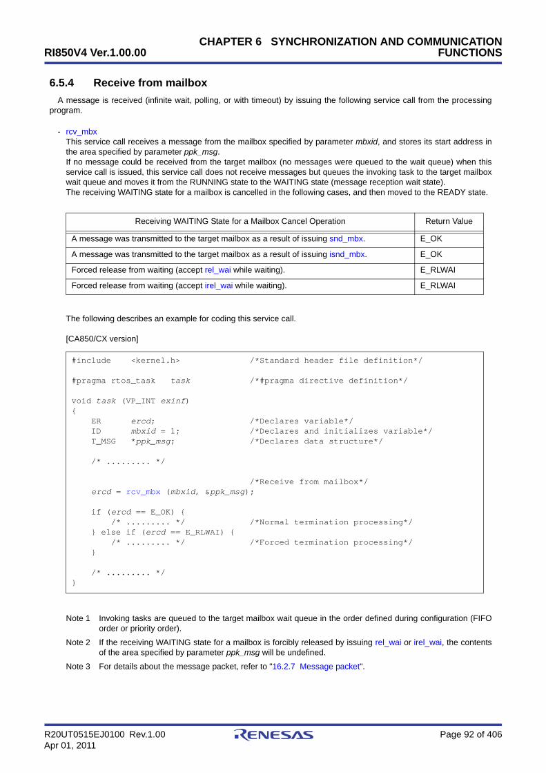
RI850V4 Ver.1.00.00
R20UT0515EJ0100 Rev.1.00 Page 92 of 406Apr 01, 2011
CHAPTER 6 SYNCHRONIZATION AND COMMUNICATIONFUNCTIONS
6.5.4 Receive from mailbox
A message is received (infinite wait, polling, or with timeout) by issuing the following service call from the processingprogram.
- rcv_mbxThis service call receives a message from the mailbox specified by parameter mbxid, and stores its start address inthe area specified by parameter ppk_msg.If no message could be received from the target mailbox (no messages were queued to the wait queue) when thisservice call is issued, this service call does not receive messages but queues the invoking task to the target mailboxwait queue and moves it from the RUNNING state to the WAITING state (message reception wait state).The receiving WAITING state for a mailbox is cancelled in the following cases, and then moved to the READY state.
The following describes an example for coding this service call.
[CA850/CX version]
Note 1 Invoking tasks are queued to the target mailbox wait queue in the order defined during configuration (FIFOorder or priority order).
Note 2 If the receiving WAITING state for a mailbox is forcibly released by issuing rel_wai or irel_wai, the contentsof the area specified by parameter ppk_msg will be undefined.
Note 3 For details about the message packet, refer to "16.2.7 Message packet".
Receiving WAITING State for a Mailbox Cancel Operation Return Value
A message was transmitted to the target mailbox as a result of issuing snd_mbx. E_OK
A message was transmitted to the target mailbox as a result of issuing isnd_mbx. E_OK
Forced release from waiting (accept rel_wai while waiting). E_RLWAI
Forced release from waiting (accept irel_wai while waiting). E_RLWAI
#include <kernel.h> /*Standard header file definition*/
#pragma rtos_task task /*#pragma directive definition*/
void task (VP_INT exinf){ ER ercd; /*Declares variable*/ ID mbxid = 1; /*Declares and initializes variable*/ T_MSG *ppk_msg; /*Declares data structure*/
/* ......... */
/*Receive from mailbox*/ ercd = rcv_mbx (mbxid, &ppk_msg);
if (ercd == E_OK) { /* ......... */ /*Normal termination processing*/ } else if (ercd == E_RLWAI) { /* ......... */ /*Forced termination processing*/ }
/* ......... */}

RI850V4 Ver.1.00.00
R20UT0515EJ0100 Rev.1.00 Page 93 of 406Apr 01, 2011
CHAPTER 6 SYNCHRONIZATION AND COMMUNICATIONFUNCTIONS
- prcv_mbx, iprcv_mbxThis service call receives a message from the mailbox specified by parameter mbxid, and stores its start address inthe area specified by parameter ppk_msg.If the message could not be received from the target mailbox (no messages were queued in the wait queue) when thisservice call is issued, message reception processing is not executed but "E_TMOUT" is returned.The following describes an example for coding this service call.
[CA850/CX version]
Note 1 If no message could be received from the target mailbox (no messages were queued to the wait queue)when this service call is issued, the contents in the area specified by parameter ppk_msg becomeundefined.
Note 2 For details about the message packet, refer to "16.2.7 Message packet".
#include <kernel.h> /*Standard header file definition*/
#pragma rtos_task task /*#pragma directive definition*/
void task (VP_INT exinf){ ER ercd; /*Declares variable*/ ID mbxid = 1; /*Declares and initializes variable*/ T_MSG *ppk_msg; /*Declares data structure*/
/* ......... */
/*Receive from mailbox (polling)*/ ercd = prcv_mbx (mbxid, &ppk_msg);
if (ercd == E_OK) { /* ......... */ /*Polling success processing*/ } else if (ercd == E_TMOUT) { /* ......... */ /*Polling failure processing*/ }
/* ......... */}

RI850V4 Ver.1.00.00
R20UT0515EJ0100 Rev.1.00 Page 94 of 406Apr 01, 2011
CHAPTER 6 SYNCHRONIZATION AND COMMUNICATIONFUNCTIONS
- trcv_mbxThis service call receives a message from the mailbox specified by parameter mbxid, and stores its start address inthe area specified by parameter ppk_msg.If no message could be received from the target mailbox (no messages were queued to the wait queue) when thisservice call is issued, this service call does not receive messages but queues the invoking task to the target mailboxwait queue and moves it from the RUNNING state to the WAITING state with timeout (message reception wait state).The receiving WAITING state for a mailbox is cancelled in the following cases, and then moved to the READY state.
The following describes an example for coding this service call.
[CA850/CX version]
Note 1 Invoking tasks are queued to the target mailbox wait queue in the order defined during configuration (FIFOorder or priority order).
Note 2 If the message reception wait state is cancelled because rel_wai or irel_wai was issued or the wait timeelapsed, the contents in the area specified by parameter ppk_msg become undefined.
Note 3 TMO_FEVR is specified for wait time tmout, processing equivalent to rcv_mbx will be executed. WhenTMO_POL is specified, processing equivalent to prcv_mbx /iprcv_mbx will be executed.
Note 4 For details about the message packet, refer to "16.2.7 Message packet".
Receiving WAITING State for a Mailbox Cancel Operation Return Value
A message was transmitted to the target mailbox as a result of issuing snd_mbx. E_OK
A message was transmitted to the target mailbox as a result of issuing isnd_mbx. E_OK
Forced release from waiting (accept rel_wai while waiting). E_RLWAI
Forced release from waiting (accept irel_wai while waiting). E_RLWAI
Polling failure or timeout. E_TMOUT
#include <kernel.h> /*Standard header file definition*/
#pragma rtos_task task /*#pragma directive definition*/
void task (VP_INT exinf){ ER ercd; /*Declares variable*/ ID mbxid = 1; /*Declares and initializes variable*/ T_MSG *ppk_msg; /*Declares data structure*/ TMO tmout = 3600; /*Declares and initializes variable*/
/* ......... */
/*Receive from mailbox (with timeout)*/ ercd = trcv_mbx (mbxid, &ppk_msg, tmout);
if (ercd == E_OK) { /* ......... */ /*Normal termination processing*/ } else if (ercd == E_RLWAI) { /* ......... */ /*Forced termination processing*/ } else if (ercd == E_TMOUT) { /* ......... */ /*Timeout processing*/ }
/* ......... */}

RI850V4 Ver.1.00.00
R20UT0515EJ0100 Rev.1.00 Page 95 of 406Apr 01, 2011
CHAPTER 6 SYNCHRONIZATION AND COMMUNICATIONFUNCTIONS
6.5.5 Reference mailbox state
A mailbox status is referenced by issuing the following service call from the processing program.
- ref_mbx, iref_mbxStores mailbox state packet (ID number of the task at the head of the wait queue, start address of the message packetat the head of the wait queue) of the mailbox specified by parameter mbxid in the area specified by parameterpk_rmbx.The following describes an example for coding this service call.
[CA850/CX version]
Note For details about the mailbox state packet, refer to "16.2.8 Mailbox state packet".
#include <kernel.h> /*Standard header file definition*/
#pragma rtos_task task /*#pragma directive definition*/
void task (VP_INT exinf){ ID mbxid = 1; /*Declares and initializes variable*/ T_RMBX pk_rmbx; /*Declares data structure*/ ID wtskid; /*Declares variable*/ T_MSG *pk_msg; /*Declares data structure*/ ATR mbxatr; /*Declares variable*/
/* ......... */
ref_mbx (mbxid, &pk_rmbx); /*Reference mailbox state*/
wtskid = pk_rmbx.wtskid; /*Reference ID number of the task at the */ /*head of the wait queue*/ pk_msg = pk_rmbx.pk_msg; /*Reference start address of the message */ /*packet at the head of the wait queue*/ mbxatr = pk_rmbx.mbxatr; /*Reference attribute*/
/* ......... */}

RI850V4 Ver.1.00.00
R20UT0515EJ0100 Rev.1.00 Page 96 of 406Apr 01, 2011
CHAPTER 7 EXTENDED SYNCHRONIZATION ANDCOMMUNICATION FUNCTIONS
CHAPTER 7 EXTENDED SYNCHRONIZATION AND COMMUNICATION FUNCTIONS
This chapter describes the extended synchronization and communication functions performed by the RI850V4.
7.1 Outline
The RI850V4 provides Mutexes as the extended synchronization and communication function for implementingexclusive control between tasks.
7.2 Mutexes
Multitask processing requires the function to prevent contentions on using the limited number of resources (A/Dconverter, coprocessor, files, or the like) simultaneously by tasks operating in parallel (exclusive control function). Toresolve such problems, the RI850V4 therefore provides "mutexes".
The following shows a processing flow when using a mutex.The mutexes provided in the RI850V4 do not support the priority inheritance protocol and priority ceiling protocol but
only support the FIFO order and priority order.
Figure 7-1 Processing Flow (Mutex)
7.2.1 Differences from semaphores
Since the mutexes of the RI850V4 do not support the priority inheritance protocol and priority ceiling protocol, so itoperates similarly to semaphores (binary semaphore) whose the maximum resource count is 1, but they differ in thefollowing points.
- A locked mutex can be unlocked (equivalent to returning of resources) only by the task that locked the mutex--> Semaphores can return resources via any task and handler.
- Unlocking is automatically performed when a task that locked the mutex is terminated (ext_tsk or ter_tsk)--> Semaphores do not return resources automatically, so they end with resources acquired.
- Semaphores can manage multiple resources (the maximum resource count can be assigned), but the maximumnumber of resources assigned to a mutex is fixed to 1.
Task
Exclusive control period
Lock mutex
Unlock mutex
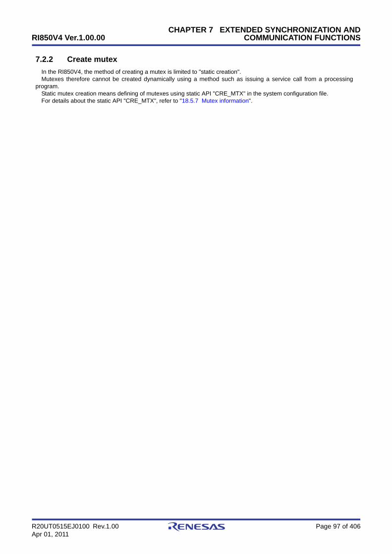
RI850V4 Ver.1.00.00
R20UT0515EJ0100 Rev.1.00 Page 97 of 406Apr 01, 2011
CHAPTER 7 EXTENDED SYNCHRONIZATION ANDCOMMUNICATION FUNCTIONS
7.2.2 Create mutex
In the RI850V4, the method of creating a mutex is limited to "static creation".Mutexes therefore cannot be created dynamically using a method such as issuing a service call from a processing
program.Static mutex creation means defining of mutexes using static API "CRE_MTX" in the system configuration file.For details about the static API "CRE_MTX", refer to "18.5.7 Mutex information".
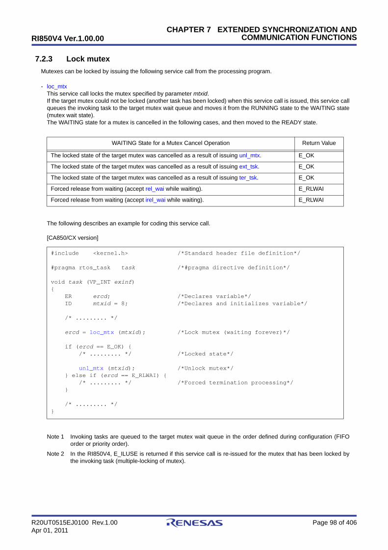
RI850V4 Ver.1.00.00
R20UT0515EJ0100 Rev.1.00 Page 98 of 406Apr 01, 2011
CHAPTER 7 EXTENDED SYNCHRONIZATION ANDCOMMUNICATION FUNCTIONS
7.2.3 Lock mutex
Mutexes can be locked by issuing the following service call from the processing program.
- loc_mtxThis service call locks the mutex specified by parameter mtxid.If the target mutex could not be locked (another task has been locked) when this service call is issued, this service callqueues the invoking task to the target mutex wait queue and moves it from the RUNNING state to the WAITING state(mutex wait state).The WAITING state for a mutex is cancelled in the following cases, and then moved to the READY state.
The following describes an example for coding this service call.
[CA850/CX version]
Note 1 Invoking tasks are queued to the target mutex wait queue in the order defined during configuration (FIFOorder or priority order).
Note 2 In the RI850V4, E_ILUSE is returned if this service call is re-issued for the mutex that has been locked bythe invoking task (multiple-locking of mutex).
WAITING State for a Mutex Cancel Operation Return Value
The locked state of the target mutex was cancelled as a result of issuing unl_mtx. E_OK
The locked state of the target mutex was cancelled as a result of issuing ext_tsk. E_OK
The locked state of the target mutex was cancelled as a result of issuing ter_tsk. E_OK
Forced release from waiting (accept rel_wai while waiting). E_RLWAI
Forced release from waiting (accept irel_wai while waiting). E_RLWAI
#include <kernel.h> /*Standard header file definition*/
#pragma rtos_task task /*#pragma directive definition*/
void task (VP_INT exinf){ ER ercd; /*Declares variable*/ ID mtxid = 8; /*Declares and initializes variable*/
/* ......... */
ercd = loc_mtx (mtxid); /*Lock mutex (waiting forever)*/
if (ercd == E_OK) { /* ......... */ /*Locked state*/
unl_mtx (mtxid); /*Unlock mutex*/ } else if (ercd == E_RLWAI) { /* ......... */ /*Forced termination processing*/ }
/* ......... */}

RI850V4 Ver.1.00.00
R20UT0515EJ0100 Rev.1.00 Page 99 of 406Apr 01, 2011
CHAPTER 7 EXTENDED SYNCHRONIZATION ANDCOMMUNICATION FUNCTIONS
- ploc_mtxThis service call locks the mutex specified by parameter mtxid.If the target mutex could not be locked (another task has been locked) when this service call is issued but E_TMOUTis returned.The following describes an example for coding this service call.
[CA850/CX version]
Note In the RI850V4, E_ILUSE is returned if this service call is re-issued for the mutex that has been locked bythe invoking task (multiple-locking of mutex).
#include <kernel.h> /*Standard header file definition*/
#pragma rtos_task task /*#pragma directive definition*/
void task (VP_INT exinf){ ER ercd; /*Declares variable*/ ID mtxid = 8; /*Declares and initializes variable*/
/* ......... */
ercd = ploc_mtx (mtxid); /*Lock mutex (polling)*/
if (ercd == E_OK) { /* ......... */ /*Polling success processing*/
unl_mtx (mtxid); /*Unlock mutex*/ } else if (ercd == E_TMOUT) { /* ......... */ /*Polling failure processing*/ }
/* ......... */}

RI850V4 Ver.1.00.00
R20UT0515EJ0100 Rev.1.00 Page 100 of 406Apr 01, 2011
CHAPTER 7 EXTENDED SYNCHRONIZATION ANDCOMMUNICATION FUNCTIONS
- tloc_mtxThis service call locks the mutex specified by parameter mtxid.If the target mutex could not be locked (another task has been locked) when this service call is issued, this service callqueues the invoking task to the target mutex wait queue and moves it from the RUNNING state to the WAITING statewith timeout (mutex wait state).The WAITING state for a mutex is cancelled in the following cases, and then moved to the READY state.
The following describes an example for coding this service call.
[CA850/CX version]
Note 1 Invoking tasks are queued to the target mutex wait queue in the order defined during configuration (FIFOorder or priority order).
Note 2 In the RI850V4, E_ILUSE is returned if this service call is re-issued for the mutex that has been locked bythe invoking task (multiple-locking of mutex).
Note 3 TMO_FEVR is specified for wait time tmout, processing equivalent to loc_mtx will be executed. WhenTMO_POL is specified, processing equivalent to ploc_mtx will be executed.
WAITING State for a Mutex Cancel Operation Return Value
The locked state of the target mutex was cancelled as a result of issuing unl_mtx. E_OK
The locked state of the target mutex was cancelled as a result of issuing ext_tsk. E_OK
The locked state of the target mutex was cancelled as a result of issuing ter_tsk. E_OK
Forced release from waiting (accept rel_wai while waiting). E_RLWAI
Forced release from waiting (accept irel_wai while waiting). E_RLWAI
Polling failure or timeout. E_TMOUT
#include <kernel.h> /*Standard header file definition*/
#pragma rtos_task task /*#pragma directive definition*/
void task (VP_INT exinf){ ER ercd; /*Declares variable*/ ID mtxid = 8; /*Declares and initializes variable*/ TMO tmout = 3600; /*Declares and initializes variable*/
/* ......... */
ercd = tloc_mtx (mtxid, tmout); /*Lock mutex (with timeout)*/
if (ercd == E_OK) { /* ......... */ /*Locked state*/
unl_mtx (mtxid); /*Unlock mutex*/ } else if (ercd == E_RLWAI) { /* ......... */ /*Forced termination processing*/ } else if (ercd == E_TMOUT) { /* ......... */ /*Timeout processing*/ }
/* ......... */}
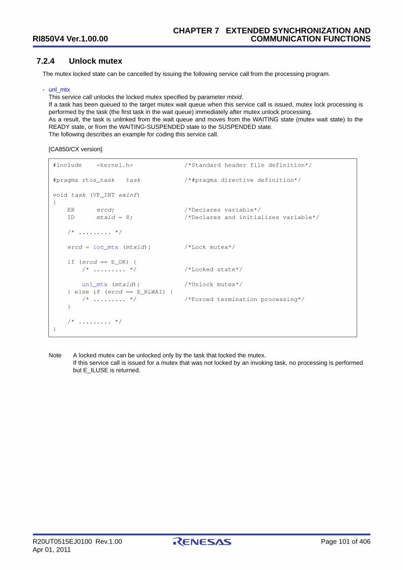
RI850V4 Ver.1.00.00
R20UT0515EJ0100 Rev.1.00 Page 101 of 406Apr 01, 2011
CHAPTER 7 EXTENDED SYNCHRONIZATION ANDCOMMUNICATION FUNCTIONS
7.2.4 Unlock mutex
The mutex locked state can be cancelled by issuing the following service call from the processing program.
- unl_mtxThis service call unlocks the locked mutex specified by parameter mtxid.If a task has been queued to the target mutex wait queue when this service call is issued, mutex lock processing isperformed by the task (the first task in the wait queue) immediately after mutex unlock processing.As a result, the task is unlinked from the wait queue and moves from the WAITING state (mutex wait state) to theREADY state, or from the WAITING-SUSPENDED state to the SUSPENDED state.The following describes an example for coding this service call.
[CA850/CX version]
Note A locked mutex can be unlocked only by the task that locked the mutex.If this service call is issued for a mutex that was not locked by an invoking task, no processing is performedbut E_ILUSE is returned.
#include <kernel.h> /*Standard header file definition*/
#pragma rtos_task task /*#pragma directive definition*/
void task (VP_INT exinf){ ER ercd; /*Declares variable*/ ID mtxid = 8; /*Declares and initializes variable*/
/* ......... */
ercd = loc_mtx (mtxid); /*Lock mutex*/
if (ercd == E_OK) { /* ......... */ /*Locked state*/
unl_mtx (mtxid); /*Unlock mutex*/ } else if (ercd == E_RLWAI) { /* ......... */ /*Forced termination processing*/ }
/* ......... */}
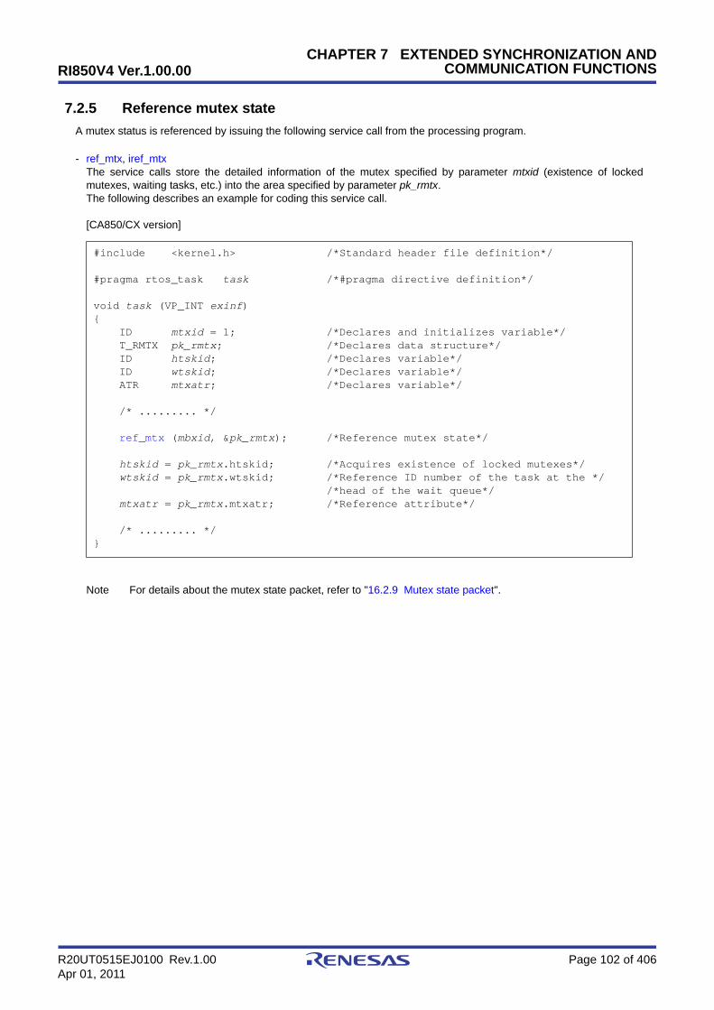
RI850V4 Ver.1.00.00
R20UT0515EJ0100 Rev.1.00 Page 102 of 406Apr 01, 2011
CHAPTER 7 EXTENDED SYNCHRONIZATION ANDCOMMUNICATION FUNCTIONS
7.2.5 Reference mutex state
A mutex status is referenced by issuing the following service call from the processing program.
- ref_mtx, iref_mtxThe service calls store the detailed information of the mutex specified by parameter mtxid (existence of lockedmutexes, waiting tasks, etc.) into the area specified by parameter pk_rmtx.The following describes an example for coding this service call.
[CA850/CX version]
Note For details about the mutex state packet, refer to "16.2.9 Mutex state packet".
#include <kernel.h> /*Standard header file definition*/
#pragma rtos_task task /*#pragma directive definition*/
void task (VP_INT exinf){ ID mtxid = 1; /*Declares and initializes variable*/ T_RMTX pk_rmtx; /*Declares data structure*/ ID htskid; /*Declares variable*/ ID wtskid; /*Declares variable*/ ATR mtxatr; /*Declares variable*/
/* ......... */
ref_mtx (mbxid, &pk_rmtx); /*Reference mutex state*/
htskid = pk_rmtx.htskid; /*Acquires existence of locked mutexes*/ wtskid = pk_rmtx.wtskid; /*Reference ID number of the task at the */ /*head of the wait queue*/ mtxatr = pk_rmtx.mtxatr; /*Reference attribute*/
/* ......... */}

RI850V4 Ver.1.00.00 CHAPTER 8 MEMORY POOL MANAGEMENT FUNCTIONS
R20UT0515EJ0100 Rev.1.00 Page 103 of 406Apr 01, 2011
CHAPTER 8 MEMORY POOL MANAGEMENT FUNC-TIONS
This chapter describes the memory pool management functions performed by the RI850V4.
8.1 Outline
The statically secured memory areas in the Kernel Initialization Module are subject to management by the memory poolmanagement functions of the RI850V4.
The RI850V4 provides a function to reference the memory area status, including the detailed information of fixed/variable-size memory pools, as well as a function to dynamically manipulate the memory area, including acquisition/release of fixed/variable-size memory blocks, by releasing a part of the memory area statically secured/initialized as"Fixed-Sized Memory Pools", or "Variable-Sized Memory Pools".
RI850V4 Ver.1.00.00 CHAPTER 8 MEMORY POOL MANAGEMENT FUNCTIONS
R20UT0515EJ0100 Rev.1.00 Page 104 of 406Apr 01, 2011
8.2 Fixed-Sized Memory Pools
When a dynamic memory manipulation request is issued from a processing program in the RI850V4, the fixed-sizedmemory pool is provided as a usable memory area.
Dynamic memory manipulation of the fixed-size memory pool is executed in fixed size memory block units.
8.2.1 Create fixed-sized memory pool
In the RI850V4, the method of creating a fixed-sized memory pool is limited to "static creation".Fixed-sized memory pools therefore cannot be created dynamically using a method such as issuing a service call from
a processing program.Static fixed-size memory pool creation means defining of fixed-size memory pools using static API "CRE_MPF" in the
system configuration file.For details about the static API "CRE_MPF", refer to "18.5.8 Fixed-sized memory pool information".

RI850V4 Ver.1.00.00 CHAPTER 8 MEMORY POOL MANAGEMENT FUNCTIONS
R20UT0515EJ0100 Rev.1.00 Page 105 of 406Apr 01, 2011
8.2.2 Acquire fixed-sized memory block
A fixed-sized memory block is acquired (waiting forever, polling, or with timeout) by issuing the following service callfrom the processing program.
- get_mpfThis service call acquires the fixed-sized memory block from the fixed-sized memory pool specified by parametermpfid and stores the start address in the area specified by parameter p_blk.If no fixed-size memory blocks could be acquired from the target fixed-size memory pool (no available fixed-sizememory blocks exist) when this service call is issued, this service call does not acquire the fixed-size memory blockbut queues the invoking task to the target fixed-size memory pool wait queue and moves it from the RUNNING stateto the WAITING state (fixed-size memory block acquisition wait state).The WAITING state for a fixed-sized memory block is cancelled in the following cases, and then moved to the READYstate.
The following describes an example for coding this service call.
[CA850/CX version]
Note 1 Invoking tasks are queued to the target fixed-size memory pool wait queue in the order defined duringconfiguration (FIFO order or priority order).
WAITING State for a Fixed-sized Memory Block Cancel Operation Return Value
A fixed-sized memory block was returned to the target fixed-sized memory pool as a result ofissuing rel_mpf. E_OK
A fixed-sized memory block was returned to the target fixed-sized memory pool as a result ofissuing irel_mpf. E_OK
Forced release from waiting (accept rel_wai while waiting). E_RLWAI
Forced release from waiting (accept irel_wai while waiting). E_RLWAI
#include <kernel.h> /*Standard header file definition*/
#pragma rtos_task task /*#pragma directive definition*/
void task (VP_INT exinf){ ER ercd; /*Declares variable*/ ID mpfid = 1; /*Declares and initializes variable*/ VP p_blk; /*Declares variable*/
/* ......... */
ercd = get_mpf (mpfid, &p_blk); /*Acquire fixed-sized memory block */ /*(waiting forever)*/
if (ercd == E_OK) { /* ......... */ /*Normal termination processing*/
rel_mpf (mpfid, p_blk); /*Release fixed-sized memory block*/ } else if (ercd == E_RLWAI) { /* ......... */ /*Forced termination processing*/ }
/* ......... */}
RI850V4 Ver.1.00.00 CHAPTER 8 MEMORY POOL MANAGEMENT FUNCTIONS
R20UT0515EJ0100 Rev.1.00 Page 106 of 406Apr 01, 2011
Note 2 If the fixed-size memory block acquisition wait state is cancelled because rel_wai or irel_wai was issued, thecontents in the area specified by parameter p_blk become undefined.

RI850V4 Ver.1.00.00 CHAPTER 8 MEMORY POOL MANAGEMENT FUNCTIONS
R20UT0515EJ0100 Rev.1.00 Page 107 of 406Apr 01, 2011
- pget_mpf, ipget_mpfThis service call acquires the fixed-sized memory block from the fixed-sized memory pool specified by parametermpfid and stores the start address in the area specified by parameter p_blk.If a fixed-sized memory block could not be acquired from the target fixed-sized memory pool (no available fixed-sizedmemory blocks exist) when this service call is issued, fixed-sized memory block acquisition processing is notperformed but "E_TMOUT" is returned.The following describes an example for coding this service call.
[CA850/CX version]
Note If no fixed-size memory blocks could be acquired from the target fixed-size memory pool (no available fixed-size memory blocks exist) when this service call is issued, the contents in the area specified by parameterp_blk become undefined.
#include <kernel.h> /*Standard header file definition*/
#pragma rtos_task task /*#pragma directive definition*/
void task (VP_INT exinf){ ER ercd; /*Declares variable*/ ID mpfid = 1; /*Declares and initializes variable*/ VP p_blk; /*Declares variable*/
/* ......... */
/*Acquire fixed-sized memory block (polling)*/ ercd = pget_mpf (mpfid, &p_blk);
if (ercd == E_OK) { /* ......... */ /*Polling success processing*/
rel_mpf (mpfid, p_blk); /*Release fixed-sized memory block*/ } else if (ercd == E_TMOUT) { /* ......... */ /*Polling failure processing*/ }
/* ......... */}
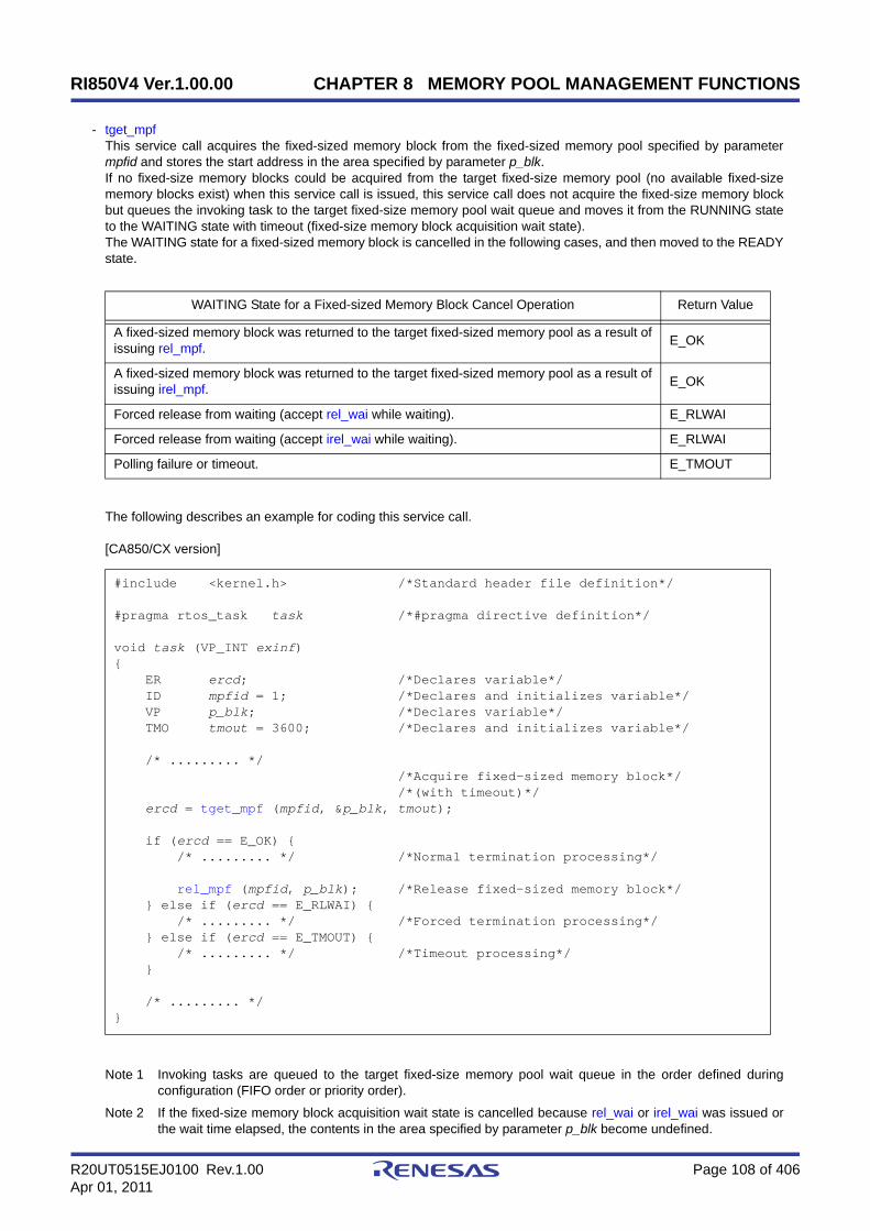
RI850V4 Ver.1.00.00 CHAPTER 8 MEMORY POOL MANAGEMENT FUNCTIONS
R20UT0515EJ0100 Rev.1.00 Page 108 of 406Apr 01, 2011
- tget_mpfThis service call acquires the fixed-sized memory block from the fixed-sized memory pool specified by parametermpfid and stores the start address in the area specified by parameter p_blk.If no fixed-size memory blocks could be acquired from the target fixed-size memory pool (no available fixed-sizememory blocks exist) when this service call is issued, this service call does not acquire the fixed-size memory blockbut queues the invoking task to the target fixed-size memory pool wait queue and moves it from the RUNNING stateto the WAITING state with timeout (fixed-size memory block acquisition wait state).The WAITING state for a fixed-sized memory block is cancelled in the following cases, and then moved to the READYstate.
The following describes an example for coding this service call.
[CA850/CX version]
Note 1 Invoking tasks are queued to the target fixed-size memory pool wait queue in the order defined duringconfiguration (FIFO order or priority order).
Note 2 If the fixed-size memory block acquisition wait state is cancelled because rel_wai or irel_wai was issued orthe wait time elapsed, the contents in the area specified by parameter p_blk become undefined.
WAITING State for a Fixed-sized Memory Block Cancel Operation Return Value
A fixed-sized memory block was returned to the target fixed-sized memory pool as a result ofissuing rel_mpf. E_OK
A fixed-sized memory block was returned to the target fixed-sized memory pool as a result ofissuing irel_mpf. E_OK
Forced release from waiting (accept rel_wai while waiting). E_RLWAI
Forced release from waiting (accept irel_wai while waiting). E_RLWAI
Polling failure or timeout. E_TMOUT
#include <kernel.h> /*Standard header file definition*/
#pragma rtos_task task /*#pragma directive definition*/
void task (VP_INT exinf){ ER ercd; /*Declares variable*/ ID mpfid = 1; /*Declares and initializes variable*/ VP p_blk; /*Declares variable*/ TMO tmout = 3600; /*Declares and initializes variable*/
/* ......... */ /*Acquire fixed-sized memory block*/ /*(with timeout)*/ ercd = tget_mpf (mpfid, &p_blk, tmout);
if (ercd == E_OK) { /* ......... */ /*Normal termination processing*/
rel_mpf (mpfid, p_blk); /*Release fixed-sized memory block*/ } else if (ercd == E_RLWAI) { /* ......... */ /*Forced termination processing*/ } else if (ercd == E_TMOUT) { /* ......... */ /*Timeout processing*/ }
/* ......... */}
RI850V4 Ver.1.00.00 CHAPTER 8 MEMORY POOL MANAGEMENT FUNCTIONS
R20UT0515EJ0100 Rev.1.00 Page 109 of 406Apr 01, 2011
Note 3 TMO_FEVR is specified for wait time tmout, processing equivalent to get_mpf will be executed. WhenTMO_POL is specified, processing equivalent to pget_mpf /ipget_mpf will be executed.

RI850V4 Ver.1.00.00 CHAPTER 8 MEMORY POOL MANAGEMENT FUNCTIONS
R20UT0515EJ0100 Rev.1.00 Page 110 of 406Apr 01, 2011
8.2.3 Release fixed-sized memory block
A fixed-sized memory block is returned by issuing the following service call from the processing program.
- rel_mpf, irel_mpfThis service call returns the fixed-sized memory block specified by parameter blk to the fixed-sized memory poolspecified by parameter mpfid.If a task is queued to the target fixed-sized memory pool wait queue when this service call is issued, fixed-sizedmemory block return processing is not performed but fixed-sized memory blocks are returned to the relevant task(first task of wait queue).As a result, the relevant task is unlinked from the wait queue and is moved from the WAITING state (WAITING statefor a fixed-sized memory block) to the READY state, or from the WAITING-SUSPENDED state to the SUSPENDEDstate.The following describes an example for coding this service call.
[CA850/CX version]
Note 1 The RI850V4 does not perform memory clear processing when returning the acquired fixed-size memoryblock. The contents of the returned fixed-size memory block are therefore undefined.
Note 2 When returning fixed-size memory blocks, be sure to issue either of these service calls for the acquiredfixed-size memory pools. If the service call is issued for another fixed-size memory pool, no error results butthe operation is not guaranteed after that.
#include <kernel.h> /*Standard header file definition*/
#pragma rtos_task task /*#pragma directive definition*/
void task (VP_INT exinf){ ER ercd; /*Declares variable*/ ID mpfid = 1; /*Declares and initializes variable*/ VP blk; /*Declares variable*/
/* ......... */
ercd = get_mpf (mpfid, &blk); /*Acquire fixed-sized memory block */ /*(waiting forever)*/
if (ercd == E_OK) { /* ......... */ /*Normal termination processing*/
rel_mpf (mpfid, blk); /*Release fixed-sized memory block*/ } else if (ercd == E_RLWAI) { /* ......... */ /*Forced termination processing*/ }
/* ......... */}
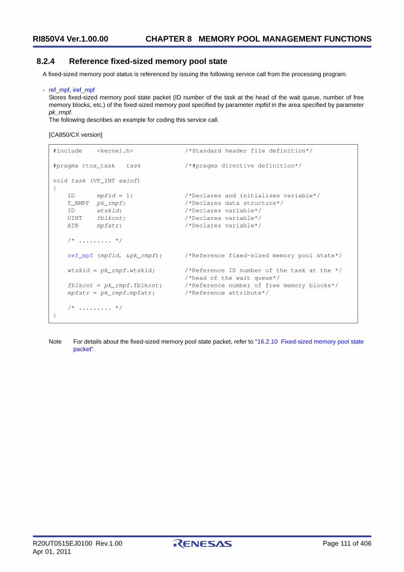
RI850V4 Ver.1.00.00 CHAPTER 8 MEMORY POOL MANAGEMENT FUNCTIONS
R20UT0515EJ0100 Rev.1.00 Page 111 of 406Apr 01, 2011
8.2.4 Reference fixed-sized memory pool state
A fixed-sized memory pool status is referenced by issuing the following service call from the processing program.
- ref_mpf, iref_mpfStores fixed-sized memory pool state packet (ID number of the task at the head of the wait queue, number of freememory blocks, etc.) of the fixed-sized memory pool specified by parameter mpfid in the area specified by parameterpk_rmpf.The following describes an example for coding this service call.
[CA850/CX version]
Note For details about the fixed-sized memory pool state packet, refer to "16.2.10 Fixed-sized memory pool statepacket".
#include <kernel.h> /*Standard header file definition*/
#pragma rtos_task task /*#pragma directive definition*/
void task (VP_INT exinf){ ID mpfid = 1; /*Declares and initializes variable*/ T_RMPF pk_rmpf; /*Declares data structure*/ ID wtskid; /*Declares variable*/ UINT fblkcnt; /*Declares variable*/ ATR mpfatr; /*Declares variable*/
/* ......... */
ref_mpf (mpfid, &pk_rmpf); /*Reference fixed-sized memory pool state*/
wtskid = pk_rmpf.wtskid; /*Reference ID number of the task at the */ /*head of the wait queue*/ fblkcnt = pk_rmpf.fblkcnt; /*Reference number of free memory blocks*/ mpfatr = pk_rmpf.mpfatr; /*Reference attribute*/
/* ......... */}
RI850V4 Ver.1.00.00 CHAPTER 8 MEMORY POOL MANAGEMENT FUNCTIONS
R20UT0515EJ0100 Rev.1.00 Page 112 of 406Apr 01, 2011
8.3 Variable-Sized Memory Pools
When a dynamic memory manipulation request is issued from a processing program in the RI850V4, the variable-sizedmemory pool is provided as a usable memory area.
Dynamic memory manipulation for variable-size memory pools is performed in the units of the specified variable-sizememory block size.
8.3.1 Create variable-sized memory pool
In the RI850V4, the method of creating a variable-sized memory pool is limited to "static creation".Variable-sized memory pools therefore cannot be created dynamically using a method such as issuing a service call
from a processing program.Static variable-size memory pool creation means defining of variable-size memory pools using static API "CRE_MPL" in
the system configuration file.For details about the static API "CRE_MPL", refer to "18.5.9 Variable-sized memory pool information".

RI850V4 Ver.1.00.00 CHAPTER 8 MEMORY POOL MANAGEMENT FUNCTIONS
R20UT0515EJ0100 Rev.1.00 Page 113 of 406Apr 01, 2011
8.3.2 Acquire variable-sized memory block
A variable-sized memory block is acquired (waiting forever, polling, or with timeout) by issuing the following service callfrom the processing program.
- get_mplThis service call acquires a variable-size memory block of the size specified by parameter blksz from the variable-sizememory pool specified by parameter mplid, and stores its start address into the area specified by parameter p_blk.If no variable-size memory blocks could be acquired from the target variable-size memory pool (no successive areasequivalent to the requested size were available) when this service call is issued, this service call does not acquirevariable-size memory blocks but queues the invoking task to the target variable-size memory pool wait queue andmoves it from the RUNNING state to the WAITING state (variable-size memory block acquisition wait state).The WAITING state for a variable-sized memory block is cancelled in the following cases, and then moved to theREADY state.
The following describes an example for coding this service call.
[CA850/CX version]
Note 1 The RI850V4 acquires variable-size memory blocks in the unit of "integral multiple of 4". If a value other thanan integral multiple of 4 is specified for parameter blksz, it is rounded up to be an integral multiple of 4.
WAITING State for a Variable-sized Memory Block Cancel Operation Return Value
The variable-size memory block that satisfies the requested size was returned to the targetvariable-size memory pool as a result of issuing rel_mpl. E_OK
The variable-size memory block that satisfies the requested size was returned to the targetvariable-size memory pool as a result of issuing irel_mpl. E_OK
Forced release from waiting (accept rel_wai while waiting). E_RLWAI
Forced release from waiting (accept irel_wai while waiting). E_RLWAI
#include <kernel.h> /*Standard header file definition*/#pragma rtos_task task /*#pragma directive definition*/
void task (VP_INT exinf){ ER ercd; /*Declares variable*/ ID mplid = 1; /*Declares and initializes variable*/ UINT blksz = 256; /*Declares and initializes variable*/ VP p_blk; /*Declares variable*/
/* ......... */ /*Acquire variable-sized memory block */ /*(waiting forever)*/ ercd = get_mpl (mplid, blksz, &p_blk);
if (ercd == E_OK) { /* ......... */ /*Normal termination processing*/
rel_mpl (mplid, p_blk); /*Release variable-sized memory block*/ } else if (ercd == E_RLWAI) { /* ......... */ /*Forced termination processing*/ }
/* ......... */}
RI850V4 Ver.1.00.00 CHAPTER 8 MEMORY POOL MANAGEMENT FUNCTIONS
R20UT0515EJ0100 Rev.1.00 Page 114 of 406Apr 01, 2011
Note 2 Invoking tasks are queued to the target variable-size memory pool wait queue in the order defined duringconfiguration (FIFO order or priority order).
Note 3 If the variable-size memory block acquisition wait state is cancelled because rel_wai or irel_wai was issued,the contents in the area specified by parameter p_blk become undefined.
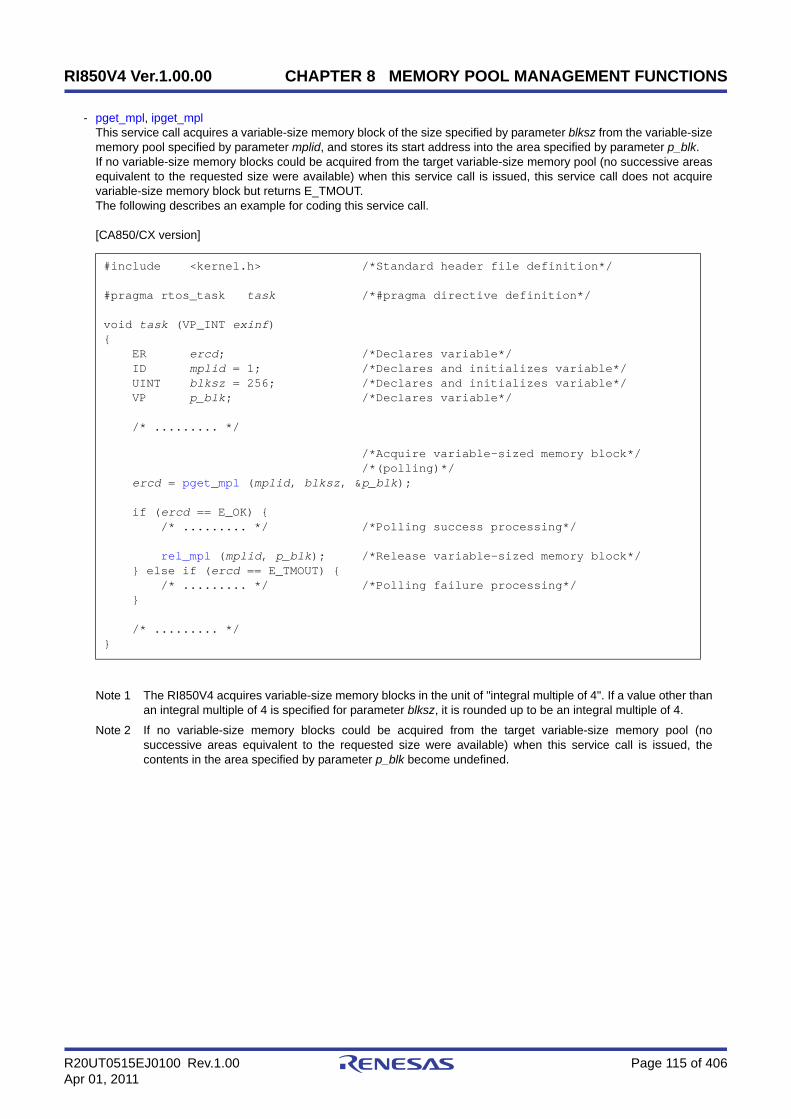
RI850V4 Ver.1.00.00 CHAPTER 8 MEMORY POOL MANAGEMENT FUNCTIONS
R20UT0515EJ0100 Rev.1.00 Page 115 of 406Apr 01, 2011
- pget_mpl, ipget_mplThis service call acquires a variable-size memory block of the size specified by parameter blksz from the variable-sizememory pool specified by parameter mplid, and stores its start address into the area specified by parameter p_blk.If no variable-size memory blocks could be acquired from the target variable-size memory pool (no successive areasequivalent to the requested size were available) when this service call is issued, this service call does not acquirevariable-size memory block but returns E_TMOUT.The following describes an example for coding this service call.
[CA850/CX version]
Note 1 The RI850V4 acquires variable-size memory blocks in the unit of "integral multiple of 4". If a value other thanan integral multiple of 4 is specified for parameter blksz, it is rounded up to be an integral multiple of 4.
Note 2 If no variable-size memory blocks could be acquired from the target variable-size memory pool (nosuccessive areas equivalent to the requested size were available) when this service call is issued, thecontents in the area specified by parameter p_blk become undefined.
#include <kernel.h> /*Standard header file definition*/
#pragma rtos_task task /*#pragma directive definition*/
void task (VP_INT exinf){ ER ercd; /*Declares variable*/ ID mplid = 1; /*Declares and initializes variable*/ UINT blksz = 256; /*Declares and initializes variable*/ VP p_blk; /*Declares variable*/
/* ......... */
/*Acquire variable-sized memory block*/ /*(polling)*/ ercd = pget_mpl (mplid, blksz, &p_blk);
if (ercd == E_OK) { /* ......... */ /*Polling success processing*/
rel_mpl (mplid, p_blk); /*Release variable-sized memory block*/ } else if (ercd == E_TMOUT) { /* ......... */ /*Polling failure processing*/ }
/* ......... */}

RI850V4 Ver.1.00.00 CHAPTER 8 MEMORY POOL MANAGEMENT FUNCTIONS
R20UT0515EJ0100 Rev.1.00 Page 116 of 406Apr 01, 2011
- tget_mplThis service call acquires a variable-size memory block of the size specified by parameter blksz from the variable-sizememory pool specified by parameter mplid, and stores its start address into the area specified by parameter p_blk.If no variable-size memory blocks could be acquired from the target variable-size memory pool (no successive areasequivalent to the requested size were available) when this service call is issued, this service call does not acquirevariable-size memory blocks but queues the invoking task to the target variable-size memory pool wait queue andmoves it from the RUNNING state to the WAITING state with timeout (variable-size memory block acquisition waitstate).The WAITING state for a variable-sized memory block is cancelled in the following cases, and then moved to theREADY state.
The following describes an example for coding this service call.
[CA850/CX version]
WAITING State for a Variable-sized Memory Block Cancel Operation Return Value
The variable-size memory block that satisfies the requested size was returned to the targetvariable-size memory pool as a result of issuing rel_mpl. E_OK
The variable-size memory block that satisfies the requested size was returned to the targetvariable-size memory pool as a result of issuing irel_mpl. E_OK
Forced release from waiting (accept rel_wai while waiting). E_RLWAI
Forced release from waiting (accept irel_wai while waiting). E_RLWAI
Polling failure or timeout. E_TMOUT
#include <kernel.h> /*Standard header file definition*/
#pragma rtos_task task /*#pragma directive definition*/
voidtask (VP_INT exinf){ ER ercd; /*Declares variable*/ ID mplid = 1; /*Declares and initializes variable*/ UINT blksz = 256; /*Declares and initializes variable*/ VP p_blk; /*Declares variable*/ TMO tmout = 3600; /*Declares and initializes variable*/
/* ......... */
/*Acquire variable-sized memory block*/ /*(with timeout)*/ ercd = tget_mpl (mplid, blksz, &p_blk, tmout);
if (ercd == E_OK) { /* ......... */ /*Normal termination processing*/
rel_mpl (mplid, p_blk ; /*Release variable-sized memory block*/ } else if (ercd == E_RLWAI) { /* ......... */ /*Forced termination processing*/ } else if (ercd == E_TMOUT) { /* ......... */ /*Timeout processing*/ }
/* ......... */}

RI850V4 Ver.1.00.00 CHAPTER 8 MEMORY POOL MANAGEMENT FUNCTIONS
R20UT0515EJ0100 Rev.1.00 Page 117 of 406Apr 01, 2011
Note 1 The RI850V4 acquires variable-size memory blocks in the unit of "integral multiple of 4". If a value other thanan integral multiple of 4 is specified for parameter blksz, it is rounded up to be an integral multiple of 4.
Note 2 Invoking tasks are queued to the target variable-size memory pool wait queue in the order defined duringconfiguration (FIFO order or priority order).
Note 3 If the variable-size memory block acquisition wait state is cancelled because rel_wai or irel_wai was issuedor the wait time elapsed, the contents in the area specified by parameter p_blk become undefined.
Note 4 TMO_FEVR is specified for wait time tmout, processing equivalent to get_mpl will be executed. WhenTMO_POL is specified, processing equivalent to pget_mpl /ipget_mpl will be executed.

RI850V4 Ver.1.00.00 CHAPTER 8 MEMORY POOL MANAGEMENT FUNCTIONS
R20UT0515EJ0100 Rev.1.00 Page 118 of 406Apr 01, 2011
8.3.3 Release variable-sized memory block
A variable-sized memory block is returned by issuing the following service call from the processing program.
- rel_mpl, irel_mplThis service call returns the variable-sized memory block specified by parameter blk to the variable-sized memorypool specified by parameter mplid.After returning the variable-size memory blocks, these service calls check the tasks queued to the target variable-sizememory pool wait queue from the top, and assigns the memory if the size of memory requested by the wait queue isavailable. This operation continues until no tasks queued to the wait queue remain or no memory space is available.As a result, the task that acquired the memory is unlinked from the queue and moved from the WAITING state(variable-size memory block acquisition wait state) to the READY state, or from the WAITING-SUSPENDED state tothe SUSPENDED state.The following describes an example for coding this service call.
[CA850/CX version]
Note 1 The RI850V4 does not perform memory clear processing when returning the acquired variable-size memoryblock. The contents of the returned variable-size memory block are therefore undefined.
Note 2 When returning variable-size memory blocks, be sure to issue either of these service calls for the acquiredvariable-size memory pools. If the service call is issued for another variable-size memory pool, no errorresults but the operation is not guaranteed after that.
#include <kernel.h> /*Standard header file definition*/
#pragma rtos_task task /*#pragma directive definition*/
void task (VP_INT exinf){ ER ercd; /*Declares variable*/ ID mplid = 1; /*Declares and initializes variable*/ UINT blksz = 256; /*Declares and initializes variable*/ VP blk; /*Declares variable*/
/* ......... */
/*Acquire variable-sized memory block*/ ercd = get_mpl (mplid, blksz, &blk);
if (ercd == E_OK) { /* ......... */ /*Normal termination processing*/
rel_mpl (mplid, blk); /*Release variable-sized memory block*/ } else if (ercd == E_RLWAI) { /* ......... */ /*Forced termination processing*/ }
/* ......... */}

RI850V4 Ver.1.00.00 CHAPTER 8 MEMORY POOL MANAGEMENT FUNCTIONS
R20UT0515EJ0100 Rev.1.00 Page 119 of 406Apr 01, 2011
8.3.4 Reference variable-sized memory pool state
A variable-sized memory pool status is referenced by issuing the following service call from the processing program.
- ref_mpl, iref_mplThese service calls store the detailed information (ID number of the task at the head of the wait queue, total size offree memory blocks, etc.) of the variable-size memory pool specified by parameter mplid into the area specified byparameter pk_rmpl.The following describes an example for coding this service call.
[CA850/CX version]
Note For details about the variable-sized memory pool state packet, refer to "16.2.11 Variable-sized memory poolstate packet".
#include <kernel.h> /*Standard header file definition*/
#pragma rtos_task task /*#pragma directive definition*/
void task (VP_INT exinf){ ID mplid = 1; /*Declares and initializes variable*/ T_RMPL pk_rmpl; /*Declares data structure*/ ID wtskid; /*Declares variable*/ SIZE fmplsz; /*Declares variable*/ UINT fblksz; /*Declares variable*/ ATR mplatr; /*Declares variable*/
/* ......... */
ref_mpl (mplid, &pk_rmpl); /*Reference variable-sized memory pool state*/
wtskid = pk_rmpl.wtskid; /*Reference ID number of the task at the */ /*head of the wait queue*/ fmplsz = pk_rmpl.fmplsz; /*Reference total size of free memory blocks*/ fblksz = pk_rmpl.fblksz; /*Reference maximum memory block size*/ mplatr = pk_rmpl.mplatr; /*Reference attribute*/
/* ......... */}

RI850V4 Ver.1.00.00 CHAPTER 9 TIME MANAGEMENT FUNCTIONS
R20UT0515EJ0100 Rev.1.00 Page 120 of 406Apr 01, 2011
CHAPTER 9 TIME MANAGEMENT FUNCTIONS
This chapter describes the time management functions performed by the RI850V4.
9.1 Outline
The RI850V4's time management function provides methods to implement time-related processing (Timer Operations:Delayed task wakeup, Timeout, Cyclic handlers) by using base clock timer interrupts that occur at constant intervals, aswell as a function to manipulate and reference the system time.
9.2 System Time
The system time is a time used by the RI850V4 for performing time management (unit: msec).After initialization by the Kernel Initialization Module, the system time is updated based on the base clock cycle defined
in Basic information (Base clock interval: clkcyc) when creating a system configuration file.
9.2.1 Base clock timer interrupt
To realize the time management function, the RI850V4 uses interrupts that occur at constant intervals (base clock timerinterrupts).
When a base clock timer interrupt occurs, processing related to the RI850V4 time (system time update, task timeout/delay, cyclic handler activation, etc.) is executed.
The sources for base clock timer interrupts can be specified in Basic information CLK_INTNO in the systemconfiguration file.
For details about the basic information "CLK_INTNO", refer to "18.4.2 Basic information".The RI850V4 does not initialize hardware to generate base clock timer interrupts, so it must be coded by the user.Initialize the hardware used by Boot processing or Initialization routine and cancel the interrupt masking.
Note Base clock timer interrupt processes are triggered by base clock timer interrupts, but ISPRn (bit correspondingto priority n of the base clock timer interrupt) in that process is set to 0. Consequently, if the base clock timerinterrupt itself, or an interrupt with lower priority than the base clock timer interrupt, is sent during a base clocktimer interrupt process, then it will be acknowledged.
9.2.2 Base clock interval
In the RI850V4, service call parameters for time specification are specified in msec units.If is desirable to set 1 msec for the occurrence interval of base clock timer interrupts, but it may be difficult depending on
the target system performance (processing capability, required time resolution, or the like).In such a case, the occurrence interval of base clock timer interrupt can be specified in Basic information DEF_TIM in
the system configuration file.For details about the basic information "DEF_TIM", refer to "18.4.2 Basic information".By specifying the base clock cycle, processing regards that the time equivalent to the base clock cycle elapses during a
base clock timer interrupt.An integer value larger than 1 can be specified for the base clock cycle. Floating-point values such as 2.5 cannot be
specified.

RI850V4 Ver.1.00.00 CHAPTER 9 TIME MANAGEMENT FUNCTIONS
R20UT0515EJ0100 Rev.1.00 Page 121 of 406Apr 01, 2011
9.3 Timer Operations
The RI850V4's timer operation function provides Delayed task wakeup, Timeout and Cyclic handlers, as the method forrealizing time-dependent processing.
9.3.1 Delayed task wakeup
Delayed wakeup the operation that makes the invoking task transit from the RUNNING state to the WAITING stateduring the interval until a given length of time has elapsed, and makes that task move from the WAITING state to theREADY state once the given length of time has elapsed.
Delayed wakeup is implemented by issuing the following service call from the processing program.
dly_tsk
9.3.2 Timeout
Timeout is the operation that makes the target task move from the RUNNING state to the WAITING state during theinterval until a given length of time has elapsed if the required condition issued from a task is not immediately satisfied,and makes that task move from the WAITING state to the READY state regardless of whether the required condition issatisfied once the given length of time has elapsed.
A timeout is implemented by issuing the following service call from the processing program.
tslp_tsk, twai_sem, twai_flg, tsnd_dtq, trcv_dtq, trcv_mbx, tloc_mtx, tget_mpf, tget_mpl
9.3.3 Cyclic handlers
The cyclic handler is a routine dedicated to cycle processing that is activated periodically at a constant interval(activation cycle).The RI850V4 handles the cyclic handler as a "non-task (module independent from tasks)". Therefore, even if a task withthe highest priority in the system is being executed, the processing is suspended when a specified activation cycle hascome, and the control is passed to the cyclic handler.
The RI850V4 manages the states in which each cyclic handler may enter and cyclic handlers themselves, by usingmanagement objects (cyclic handler control blocks) corresponding to cyclic handlers one-to-one.
- Basic form of cyclic handlersWhen coding a cyclic handler, use a void function with one VP_INT argument (any function name is fine). The extended information specified with Cyclic handler information is set for the exinf argument.The following shows the basic form of cyclic handlers in C.
[CA850/CX version, CCV850/CCV850E version]
- Coding methodCode cyclic handlers using C or assembly language.When coding in C, they can be coded in the same manner as void type functions coded.When coding in assembly language, code them according to the calling rules prescribed in the compiler used.
- Stack switchingThe RI850V4 switches to the system stack specified in Basic information when passing control to a cyclic handler,
#include <kernel.h> /*Standard header file definition*/
void cychdr (VP_INT exinf){ /* ......... */
return; /*Terminate cyclic handler*/}
RI850V4 Ver.1.00.00 CHAPTER 9 TIME MANAGEMENT FUNCTIONS
R20UT0515EJ0100 Rev.1.00 Page 122 of 406Apr 01, 2011
and switches to the relevant stack when returning control to the processing program for which a base clock timerinterrupt occurred. Therefore, the system stack is used during cyclic handler processing.
- Service call issuanceThe RI850V4 handles the cyclic handler as a "non-task".Service calls that can be issued in cyclic handlers are limited to the service calls that can be issued from non-tasks.
Note 1 If a service call (isig_sem, iset_flg, etc.) accompanying dispatch processing (task scheduling processing) isissued in order to quickly complete the processing in the cyclic handler during the interval until theprocessing in the cyclic handler ends, the RI850V4 executes only processing such as queue manipulation,counter manipulation, etc., and the actual dispatch processing is delayed until a return instruction is issuedby the cyclic handler, upon which the actual dispatch processing is performed in batch.
Note 2 For details on the valid issuance range of each service call, refer to Table 17-1 to Table 17-14.
- Acknowledgment of maskable interrupts (the ID flag of PSW)When the handler starts, the acknowledgement of maskable interrupts is enabled (PSW ID flag is 0).It is possible to change the maskable interrupt acknowledgement status from inside a process. The changed status isnot passed on when control shifts to the processing program after the task process ends.
Note 1 Cyclic handlers are triggered by base clock timer interrupts, but ISPRn (bit corresponding to priority n of thebase clock timer interrupt) in that process is set to 0. Consequently, if the base clock timer interrupt itself oran interrupt with lower priority than the base clock timer interrupt is sent during a cyclic handler process, thenit will be acknowledged.
Note 2 When a base clock timer interrupt is acknowledged in a cyclic handler, and the cycle time of that cyclichandler has elapsed, then multiple instances of that cyclic handler will be running simultaneously.
Note 3 It is not possible to completely disable the acknowledgement of maskable interrupts from within a cyclichandler. Although it is possible to disable the acknowledgement of maskable interrupts after the cyclichandler starts by setting the PSW ID flag to 1, it is possible that maskable interrupts will be acknowledgedbetween the time the cyclic handler starts and the acknowledgement of maskable interrupts is disabled.
9.3.4 Create cyclic handler
In the RI850V4, the method of creating a cyclic handler is limited to "static creation".Cyclic handlers therefore cannot be created dynamically using a method such as issuing a service call from a
processing program.Static cyclic handler creation means defining of cyclic handlers using static API "CRE_CYC" in the system configuration
file.For details about the static API "CRE_CYC", refer to "18.5.10 Cyclic handler information".
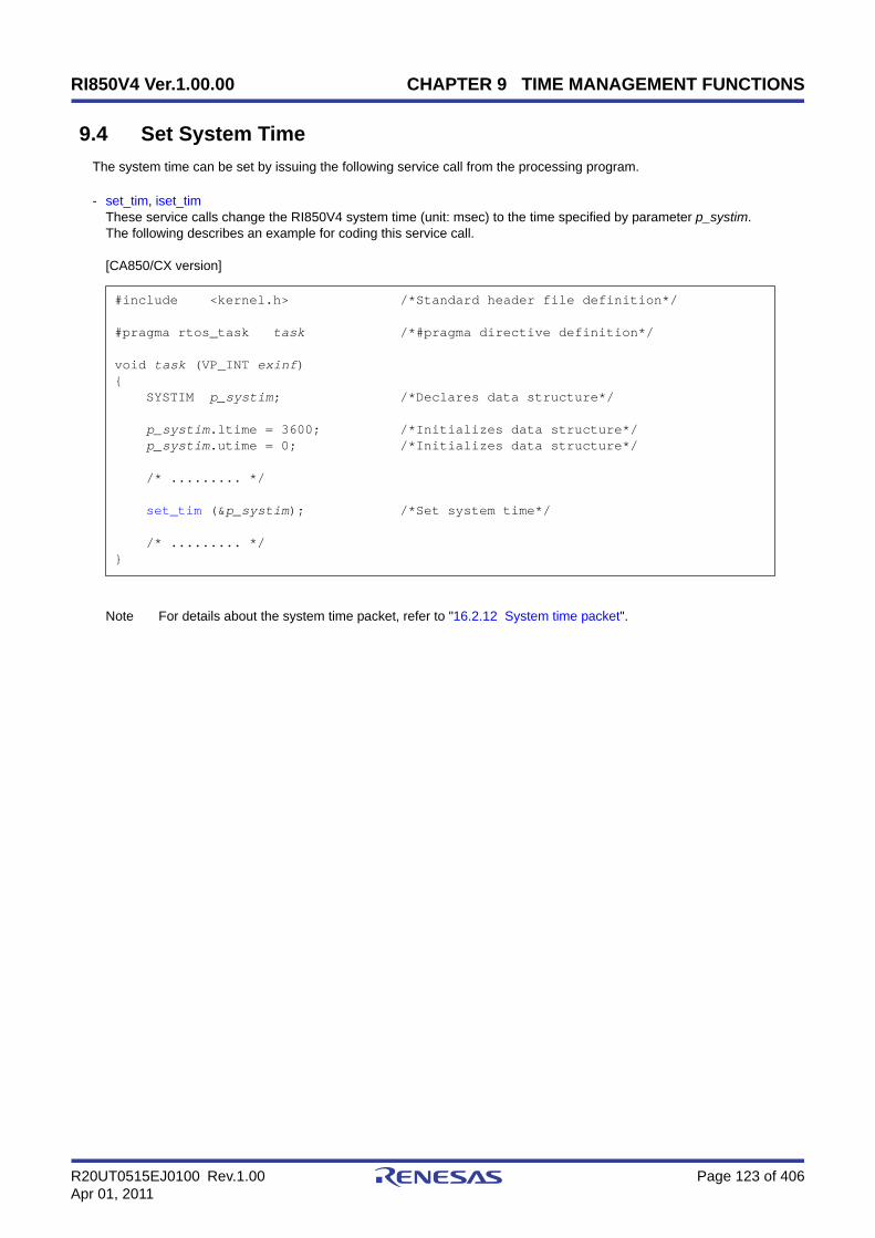
RI850V4 Ver.1.00.00 CHAPTER 9 TIME MANAGEMENT FUNCTIONS
R20UT0515EJ0100 Rev.1.00 Page 123 of 406Apr 01, 2011
9.4 Set System Time
The system time can be set by issuing the following service call from the processing program.
- set_tim, iset_timThese service calls change the RI850V4 system time (unit: msec) to the time specified by parameter p_systim.The following describes an example for coding this service call.
[CA850/CX version]
Note For details about the system time packet, refer to "16.2.12 System time packet".
#include <kernel.h> /*Standard header file definition*/
#pragma rtos_task task /*#pragma directive definition*/
void task (VP_INT exinf){ SYSTIM p_systim; /*Declares data structure*/
p_systim.ltime = 3600; /*Initializes data structure*/ p_systim.utime = 0; /*Initializes data structure*/
/* ......... */
set_tim (&p_systim); /*Set system time*/
/* ......... */}

RI850V4 Ver.1.00.00 CHAPTER 9 TIME MANAGEMENT FUNCTIONS
R20UT0515EJ0100 Rev.1.00 Page 124 of 406Apr 01, 2011
9.5 Reference System Time
The system time can be referenced by issuing the following service call from the processing program.
- get_tim, iget_timThese service calls store the RI850V4 system time (unit: msec) into the area specified by parameter p_systim.The following describes an example for coding this service call.
[CA850/CX version]
Note 1 The RI850V4 ignores the numeric values that cannot be expressed as the system time (values overflowedfrom the 48-bit width).
Note 2 For details about the system time packet, refer to "16.2.12 System time packet".
#include <kernel.h> /*Standard header file definition*/
#pragma rtos_task task /*#pragma directive definition*/
void task (VP_INT exinf){ SYSTIM p_systim; /*Declares data structure*/ UW ltime; /*Declares variable*/ UH utime; /*Declares variable*/
/* ......... */
get_tim (&p_systim); /*Reference System Time*/
ltime = p_systim.ltime; /*Acquirer system time (lower 32 bits)*/ utime = p_systim.utime; /*Acquirer system time (higher 16 bits)*/
/* ......... */}

RI850V4 Ver.1.00.00 CHAPTER 9 TIME MANAGEMENT FUNCTIONS
R20UT0515EJ0100 Rev.1.00 Page 125 of 406Apr 01, 2011
9.6 Start Cyclic Handler Operation
Moving to the operational state (STA state) is implemented by issuing the following service call from the processingprogram.
- sta_cyc, ista_cycThis service call moves the cyclic handler specified by parameter cycid from the non-operational state (STP state) tooperational state (STA state).As a result, the target cyclic handler is handled as an activation target of the RI850V4.The relative interval from when either of this service call is issued until the first activation request is issued variesdepending on whether the TA_PHS attribute is specified for the target cyclic handler during configuration.
- If the TA_PHS attribute is specifiedThe target cyclic handler activation timing is set based on the activation phases (initial activation phase cycphsand activation cycle cyctim) defined during configuration.If the target cyclic handler has already been started, however, no processing is performed even if this service callis issued, but it is not handled as an error.The following shows a cyclic handler activation timing image.
Figure 9-1 TA_PHS Attribute: Specified
- If the TA_PHS attribute is not specifiedThe target cyclic handler activation timing is set based on the activation phase (activation cycle cyctim) when thisservice call is issued.This setting is performed regardless of the operating status of the target cyclic handler.The following shows a cyclic handler activation timing image.
Figure 9-2 TA_PHS Attribute: Not Specified
The following describes an example for coding this service call.
[CA850/CX version]
#include <kernel.h> /*Standard header file definition*/
#pragma rtos_task task /*#pragma directive definition*/
void task (VP_INT exinf)
cycphs cyctim cyctim cyctim
Generation processing completed
Start Start Start Start
Start cyclic handler operation Start cyclic handler operation
cycphs cyctim cyctim cyctim
Generation processing completed
cyctim cyctim
Startcyctim cyctim
Start Start
Start cyclic handler operation Start cyclic handler operation

RI850V4 Ver.1.00.00 CHAPTER 9 TIME MANAGEMENT FUNCTIONS
R20UT0515EJ0100 Rev.1.00 Page 126 of 406Apr 01, 2011
{ ID cycid = 1; /*Declares and initializes variable*/
/* ......... */
sta_cyc (cycid); /*Start cyclic handler operation*/
/* ......... */}
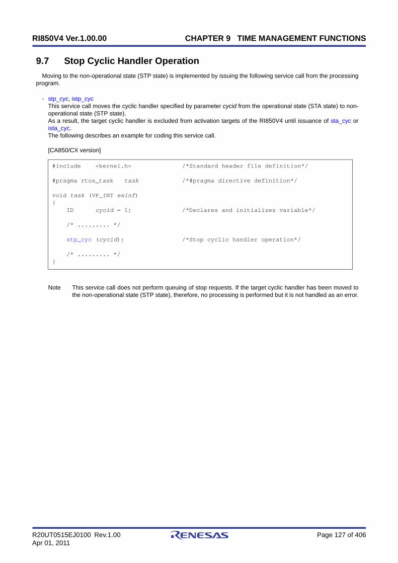
RI850V4 Ver.1.00.00 CHAPTER 9 TIME MANAGEMENT FUNCTIONS
R20UT0515EJ0100 Rev.1.00 Page 127 of 406Apr 01, 2011
9.7 Stop Cyclic Handler Operation
Moving to the non-operational state (STP state) is implemented by issuing the following service call from the processingprogram.
- stp_cyc, istp_cycThis service call moves the cyclic handler specified by parameter cycid from the operational state (STA state) to non-operational state (STP state).As a result, the target cyclic handler is excluded from activation targets of the RI850V4 until issuance of sta_cyc orista_cyc.The following describes an example for coding this service call.
[CA850/CX version]
Note This service call does not perform queuing of stop requests. If the target cyclic handler has been moved tothe non-operational state (STP state), therefore, no processing is performed but it is not handled as an error.
#include <kernel.h> /*Standard header file definition*/
#pragma rtos_task task /*#pragma directive definition*/
void task (VP_INT exinf){ ID cycid = 1; /*Declares and initializes variable*/
/* ......... */
stp_cyc (cycid); /*Stop cyclic handler operation*/
/* ......... */}
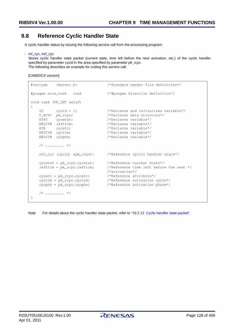
RI850V4 Ver.1.00.00 CHAPTER 9 TIME MANAGEMENT FUNCTIONS
R20UT0515EJ0100 Rev.1.00 Page 128 of 406Apr 01, 2011
9.8 Reference Cyclic Handler State
A cyclic handler status by issuing the following service call from the processing program.
- ref_cyc, iref_cycStores cyclic handler state packet (current state, time left before the next activation, etc.) of the cyclic handlerspecified by parameter cycid in the area specified by parameter pk_rcyc.The following describes an example for coding this service call.
[CA850/CX version]
Note For details about the cyclic handler state packet, refer to "16.2.13 Cyclic handler state packet".
#include <kernel.h> /*Standard header file definition*/
#pragma rtos_task task /*#pragma directive definition*/
void task (VP_INT exinf){ ID cycid = 1; /*Declares and initializes variable*/ T_RCYC pk_rcyc; /*Declares data structure*/ STAT cycstat; /*Declares variable*/ RELTIM lefttim; /*Declares variable*/ ATR cycatr; /*Declares variable*/ RELTIM cyctim; /*Declares variable*/ RELTIM cycphs; /*Declares variable*/
/* ......... */
ref_cyc (cycid, &pk_rcyc); /*Reference cyclic handler state*/
cycstat = pk_rcyc.cycstat; /*Reference current state*/ lefttim = pk_rcyc.lefttim; /*Reference time left before the next */ /*activation*/ cycatr = pk_rcyc.cycatr; /*Reference attribute*/ cyctim = pk_rcyc.cyctim; /*Reference activation cycle*/ cycphs = pk_rcyc.cycphs; /*Reference activation phase*/
/* ......... */}

RI850V4 Ver.1.00.00 CHAPTER 10 SYSTEM STATE MANAGEMENT FUNCTIONS
R20UT0515EJ0100 Rev.1.00 Page 129 of 406Apr 01, 2011
CHAPTER 10 SYSTEM STATE MANAGEMENT FUNC-TIONS
This chapter describes the system management functions performed by the RI850V4.
10.1 Outline
The RI850V4's system status management function provides functions for referencing the system status such as thecontext type and CPU lock status, as well as functions for manipulating the system status sych as ready queue rotation,scheduler activation, or the like.
10.2 Rotate Task Precedence
A ready queue is rotated by issuing the following service call from the processing program.
- rot_rdq, irot_rdqThis service call re-queues the first task of the ready queue corresponding to the priority specified by parameter tskprito the end of the queue to change the task execution order explicitly.The following shows the status transition when this service call is used.
Figure 10-1 Rotate Task Precedence
Task ARUNNING state
Task BREADY state
Task CREADY state
Ready queue
tskpri
tskpri + 1
tskpri - 1
1
maxtpri
Task BRUNNING state
Task CREADY state
Task AREADY statetskpri
tskpri + 1
tskpri - 1
1
maxtpri
Ready queue
Rotate task precedence

RI850V4 Ver.1.00.00 CHAPTER 10 SYSTEM STATE MANAGEMENT FUNCTIONS
R20UT0515EJ0100 Rev.1.00 Page 130 of 406Apr 01, 2011
The following describes an example for coding this service call.
[CA850/CX version, CCV850/CCV850E version]
Note 1 This service call does not perform queuing of rotation requests. If no task is queued to the ready queuecorresponding to the relevant priority, therefore, no processing is performed but it is not handled as an error.
Note 2 Round-robin scheduling can be implemented by issuing this service call via a cyclic handler in a constantcycle.
Note 3 The ready queue is a hash table that uses priority as the key, and tasks that have entered an executablestate (READY state or RUNNING state) are queued in FIFO order.Therefore, the scheduler realizes the RI850V4's scheduling system by executing task detection processingfrom the highest priority level of the ready queue upon activation, and upon detection of queued tasks, givingthe CPU use right to the first task of the proper priority level.
#include <kernel.h> /*Standard header file definition*/
void cychdr (VP_INT exinf){ PRI tskpri = 8; /*Declares and initializes variable*/
/* ......... */
irot_rdq (tskpri); /*Rotate task precedence*/
/* ......... */
return; /*Terminate cyclic handler*/}

RI850V4 Ver.1.00.00 CHAPTER 10 SYSTEM STATE MANAGEMENT FUNCTIONS
R20UT0515EJ0100 Rev.1.00 Page 131 of 406Apr 01, 2011
10.3 Forced Scheduler Activation
The scheduler can be forcibly activated by issuing the following service call from the processing program.
- vsta_schThis service call explicitly forces the RI850V4 scheduler to activate. If a scheduling request has been kept pending,task switching may therefore occur.The following describes an example for coding this service call.
[CA850/CX version]
Note The RI850V4 provides this service call as a function to activate a scheduler from a task for which preemptacknowledge status disable is defined during configuration.
#include <kernel.h> /*Standard header file definition*/
#pragma rtos_task task /*#pragma directive definition*/
void task (VP_INT exinf){
/* ......... */
vsta_sch (); /*Forced scheduler*/
/* ......... */}

RI850V4 Ver.1.00.00 CHAPTER 10 SYSTEM STATE MANAGEMENT FUNCTIONS
R20UT0515EJ0100 Rev.1.00 Page 132 of 406Apr 01, 2011
10.4 Reference Task ID in the RUNNING State
A RUNNING-state task is referenced by issuing the following service call from the processing program.
- get_tid, iget_tidThese service calls store the ID of a task in the RUNNING state in the area specified by parameter p_tskid.The following describes an example for coding this service call.
[CA850/CX version, CCV850/CCV850E version]
Note This service call stores TSK_NONE in the area specified by parameter p_tskid if no tasks that have enteredthe RUNNING state exist (all tasks in the IDLE state).
#include <kernel.h> /*Standard header file definition*/
void inthdr (void){ ID p_tskid; /*Declares variable*/
/* ......... */
iget_tid (&p_tskid); /*Reference task ID in the RUNNING state*/
/* ......... */
return; /*Terminate interrupt handler*/}

RI850V4 Ver.1.00.00 CHAPTER 10 SYSTEM STATE MANAGEMENT FUNCTIONS
R20UT0515EJ0100 Rev.1.00 Page 133 of 406Apr 01, 2011
10.5 Lock the CPU
A task is moved to the CPU locked state by issuing the following service call from the processing program.
- loc_cpu, iloc_cpuThese service calls change the system status type to the CPU locked state.As a result, maskable interrupt acknowledgment processing is prohibited during the interval from this service call isissued until unl_cpu or iunl_cpu is issued, and service call issuance is also restricted.The service calls that can be issued in the CPU locked state are limited to the one listed below.
If a maskable interrupt is created during this period, the RI850V4 delays transition to the relevant interrupt processing(interrupt handler) until either unl_cpu or iunl_cpu is issued.The following shows a processing flow when using this service call.
Figure 10-2 Lock the CPU
Service Call Function
sns_tex Reference task exception handling state.
loc_cpu, iloc_cpu Lock the CPU.
unl_cpu, iunl_cpu Unlock the CPU.
sns_loc Reference CPU state.
sns_dsp Reference dispatching state.
sns_ctx Reference contexts.
sns_dpn Reference dispatch pending state.
Task
return
Interrupt
Interrupt handler
Suppressed period
Lock the CPU
Unlock the CPU

RI850V4 Ver.1.00.00 CHAPTER 10 SYSTEM STATE MANAGEMENT FUNCTIONS
R20UT0515EJ0100 Rev.1.00 Page 134 of 406Apr 01, 2011
The following describes an example for coding this service call.
[CA850/CX version]
Note 1 The internal processing (interrupt mask setting processing and interrupt mask acquire processing)performed by this service call depends on the user execution environment, so it is extracted as a target-dependent module and provided as sample source files.In sample source files, manipulation for the interrupt control register xxICn and the interrupt mask flagxxMKn of the interrupt mask register IMRm is coded as interrupt mask setting processing or interrupt maskacquire processing.
Note 2 The CPU locked state changed by issuing this service call must be cancelled before the processing programthat issued this service call ends.
Note 3 This service call does not perform queuing of lock requests. If the system is in the CPU locked state,therefore, no processing is performed but it is not handled as an error.
Note 4 The RI850V4 realizes the TIME MANAGEMENT FUNCTIONS by using base clock timer interrupts thatoccur at constant intervals. If acknowledgment of the relevant base clock timer interrupt is disabled byissuing this service call, the TIME MANAGEMENT FUNCTIONS may no longer operate normally.
Note 5 If this service call or a service call other than sns_xxx is issued from when this service call is issued untilunl_cpu or iunl_cpu is issued, the RI850V4 returns E_CTX.
#include <kernel.h> /*Standard header file definition*/
#pragma rtos_task task /*#pragma directive definition*/
void task (VP_INT exinf){ /* ......... */
loc_cpu (); /*Lock the CPU*/
/* ......... */ /*CPU locked state*/
unl_cpu (); /*Unlock the CPU*/
/* ......... */}

RI850V4 Ver.1.00.00 CHAPTER 10 SYSTEM STATE MANAGEMENT FUNCTIONS
R20UT0515EJ0100 Rev.1.00 Page 135 of 406Apr 01, 2011
10.6 Unlock the CPU
The CPU locked state is cancelled by issuing the following service call from the processing program.
- unl_cpu, iunl_cpuThese service calls change the system status to the CPU unlocked state.As a result, acknowledge processing of maskable interrupts prohibited through issuance of either loc_cpu or iloc_cpuis enabled, and the restriction on service call issuance is released.If a maskable interrupt is created during the interval from when either loc_cpu or iloc_cpu is issued until this servicecall is issued, the RI850V4 delays transition to the relevant interrupt processing (interrupt handler) until this servicecall is issued.The following shows a processing flow when using this service call.
Figure 10-3 Unlock the CPU
The following describes an example for coding this service call.
[CA850/CX version]
#include <kernel.h> /*Standard header file definition*/
#pragma rtos_task task /*#pragma directive definition*/
void task (VP_INT exinf){ /* ......... */
loc_cpu (); /*Lock the CPU*/
/* ......... */ /*CPU locked state*/
unl_cpu (); /*Unlock the CPU*/
Task
return
Interrupt
Interrupt handler
Suppressed peiod
Lock the CPU
Unlock the CPU

RI850V4 Ver.1.00.00 CHAPTER 10 SYSTEM STATE MANAGEMENT FUNCTIONS
R20UT0515EJ0100 Rev.1.00 Page 136 of 406Apr 01, 2011
Note 1 The internal processing (interrupt mask setting processing) performed by this service call depends on theuser execution environment, so it is extracted as a target-dependent module and provided as sample sourcefiles.In sample source files, manipulation for the interrupt control register xxICn and the interrupt mask flagxxMKn of the interrupt mask register IMRm is coded as interrupt mask setting processing.
Note 2 This service call does not perform queuing of cancellation requests. If the system is in the CPU unlockedstate, therefore, no processing is performed but it is not handled as an error.
Note 3 This service call does not cancel the dispatch disabled state that was set by issuing dis_dsp. If the systemstatus before the CPU locked state is entered was the dispatch disabled state, the system status becomesthe dispatch disabled state after this service call is issued.
Note 4 This service call does not enable acknowledgment of the maskable interrupts that has been disabled byissuing dis_int. If the system status before the CPU locked state is entered was the maskable interruptacknowledgment enabled state, acknowledgment of maskable interrupts is disabled after this service call isissued.
Note 5 If a service call other than loc_cpu, iloc_cpu and sns_xxx is issued from when loc_cpu or iloc_cpu is issueduntil this service call is issued, the RI850V4 returns E_CTX.
/* ......... */}

RI850V4 Ver.1.00.00 CHAPTER 10 SYSTEM STATE MANAGEMENT FUNCTIONS
R20UT0515EJ0100 Rev.1.00 Page 137 of 406Apr 01, 2011
10.7 Reference CPU State
The CPU locked state is referenced by issuing the following service call from the processing program.
- sns_locThis service call acquires the system status type when this service call is issued (CPU locked state or CPU unlockedstate).When this service call is terminated normally, the acquired system state type (TRUE: CPU locked state, FALSE: CPUunlocked state) is returned.The following describes an example for coding this service call.
[CA850/CX version]
#include <kernel.h> /*Standard header file definition*/
#pragma rtos_task task /*#pragma directive definition*/
void task (VP_INT exinf){ BOOL ercd; /*Declares variable*/
/* ......... */
ercd = sns_loc (); /*Reference CPU state*/
if (ercd == TRUE) { /* ......... */ /*CPU locked state*/ } else if (ercd == FALSE) { /* ......... */ /*CPU unlocked state*/ }
/* ......... */}

RI850V4 Ver.1.00.00 CHAPTER 10 SYSTEM STATE MANAGEMENT FUNCTIONS
R20UT0515EJ0100 Rev.1.00 Page 138 of 406Apr 01, 2011
10.8 Disable Dispatching
A task is moved to the dispatch disabled state by issuing the following service call from the processing program.
- dis_dspThis service call changes the system status to the dispatch disabled state.As a result, dispatch processing (task scheduling) is disabled from when this service call is issued until ena_dsp isissued.If a service call (chg_pri, sig_sem, etc.) accompanying dispatch processing is issued during the interval from whenthis service call is issued until ena_dsp is issued, the RI850V4 executes only processing such as queue manipulation,counter manipulation, etc., and the actual dispatch processing is delayed until ena_dsp is issued, upon which theactual dispatch processing is performed in batch.The following shows a processing flow when using this service call.
Figure 10-4 Disable Dispatching
The following describes an example for coding this service call.
[CA850/CX version]
Note 1 The dispatch disabled state changed by issuing this service call must be cancelled before the task thatissued this service call moves to the DORMANT state.
#include <kernel.h> /*Standard header file definition*/
#pragma rtos_task task /*#pragma directive definition*/
void task (VP_INT exinf){ /* ......... */
dis_dsp (); /*Disable dispatching*/
/* ......... */ /*Dispatching disabled state*/
ena_dsp (); /*Enable dispatching*/
/* ......... */}
Release semaphore resource
Acquire semaphore resource
Disable Dispatching
Enable Dispatching
Task APriority: High
Task BPriority: Low
Suppressed period

RI850V4 Ver.1.00.00 CHAPTER 10 SYSTEM STATE MANAGEMENT FUNCTIONS
R20UT0515EJ0100 Rev.1.00 Page 139 of 406Apr 01, 2011
Note 2 This service call does not perform queuing of disable requests. If the system is in the dispatch disabled state,therefore, no processing is performed but it is not handled as an error.
Note 3 If a service call (such as wai_sem, wai_flg) that may move the status of an invoking task is issued from whenthis service call is issued until ena_dsp is issued, the RI850V4 returns E_CTX regardless of whether therequired condition is immediately satisfied.

RI850V4 Ver.1.00.00 CHAPTER 10 SYSTEM STATE MANAGEMENT FUNCTIONS
R20UT0515EJ0100 Rev.1.00 Page 140 of 406Apr 01, 2011
10.9 Enable Dispatching
The dispatch disabled state is cancelled by issuing the following service call from the processing program.
- ena_dspThis service call changes the system status to the dispatch enabled state.As a result, dispatch processing (task scheduling) that has been disabled by issuing dis_dsp is enabled.If a service call (chg_pri, sig_sem, etc.) accompanying dispatch processing is issued during the interval from whendis_dsp is issued until this service call is issued, the RI850V4 executes only processing such as queue manipulation,counter manipulation, etc., and the actual dispatch processing is delayed until this service call is issued, upon whichthe actual dispatch processing is performed in batch.The following shows a processing flow when using this service call.
Figure 10-5 Enable Dispatching
The following describes an example for coding this service call.
[CA850/CX version]
Note 1 This service call does not perform queuing of enable requests. If the system is in the dispatch enabled state,therefore, no processing is performed but it is not handled as an error.
#include <kernel.h> /*Standard header file definition*/
#pragma rtos_task task /*#pragma directive definition*/
void task (VP_INT exinf){ /* ......... */
dis_dsp (); /*Disable dispatching*/
/* ......... */ /*Dispatching disabled state*/
ena_dsp (); /*Enable dispatching*/
/* ......... */}
Release semaphore resource
Acquire semaphore resource
Disable Dispatching
Enable Dispatching
Task APriority: High
Task BPriority: Low
Suppressed period

RI850V4 Ver.1.00.00 CHAPTER 10 SYSTEM STATE MANAGEMENT FUNCTIONS
R20UT0515EJ0100 Rev.1.00 Page 141 of 406Apr 01, 2011
Note 2 If a service call (such as wai_sem, wai_flg) that may move the status of an invoking task is issued from whendis_dsp is issued until this service call is issued, the RI850V4 returns E_CTX regardless of whether therequired condition is immediately satisfied.

RI850V4 Ver.1.00.00 CHAPTER 10 SYSTEM STATE MANAGEMENT FUNCTIONS
R20UT0515EJ0100 Rev.1.00 Page 142 of 406Apr 01, 2011
10.10 Reference Dispatching State
The dispatch disabled state is referenced by issuing the following service call from the processing program.
- sns_dspThis service call acquires the system status type when this service call is issued (dispatch disabled state or dispatchenabled state).When this service call is terminated normally, the acquired system state type (TRUE: dispatch disabled state, FALSE:dispatch enabled state) is returned.The following describes an example for coding this service call.
[CA850/CX version]
#include <kernel.h> /*Standard header file definition*/
#pragma rtos_task task /*#pragma directive definition*/
void task (VP_INT exinf){ BOOL ercd; /*Declares variable*/
/* ......... */
ercd = sns_dsp (); /*Reference dispatching state*/
if (ercd == TRUE) { /* ......... */ /*Dispatching disabled state*/ } else if (ercd == FALSE) { /* ......... */ /*Dispatching enabled state*/ }
/* ......... */}

RI850V4 Ver.1.00.00 CHAPTER 10 SYSTEM STATE MANAGEMENT FUNCTIONS
R20UT0515EJ0100 Rev.1.00 Page 143 of 406Apr 01, 2011
10.11 Reference Contexts
The context type is referenced by issuing the following service call from the processing program.
- sns_ctxThis service call acquires the context type of the processing program that issued this service call (non-task context ortask context).When this service call is terminated normally, the acquired context type (TRUE: non-task context, FALSE: taskcontext) is returned.The following describes an example for coding this service call.
[CA850/CX version]
#include <kernel.h> /*Standard header file definition*/
#pragma rtos_task task /*#pragma directive definition*/
void task (VP_INT exinf){ BOOL ercd; /*Declares variable*/
/* ......... */
ercd = sns_ctx (); /*Reference contexts*/
if (ercd == TRUE) { /* ......... */ /*Non-task contexts*/ } else if (ercd == FALSE) { /* ......... */ /*Task contexts*/ }
/* ......... */}

RI850V4 Ver.1.00.00 CHAPTER 10 SYSTEM STATE MANAGEMENT FUNCTIONS
R20UT0515EJ0100 Rev.1.00 Page 144 of 406Apr 01, 2011
10.12 Reference Dispatch Pending State
The dispatch pending state is referenced by issuing the following service call from the processing program.
- sns_dpnThis service call acquires the system status type when this service call is issued (whether in dispatch pending state ornot).When this service call is terminated normally, the acquired system state type (TRUE: dispatch pending state, FALSE:dispatch not-pending state) is returned.The following describes an example for coding this service call.
[CA850/CX version]
#include <kernel.h> /*Standard header file definition*/
#pragma rtos_task task /*#pragma directive definition*/
void task (VP_INT exinf){ BOOL ercd; /*Declares variable*/
/* ......... */
ercd = sns_dpn (); /*Reference dispatch pending state*/
if (ercd == TRUE) { /* ......... */ /*Dispatch pending state*/ } else if (ercd == FALSE) { /* ......... */ /*Other state*/ }
/* ......... */}

RI850V4 Ver.1.00.00 CHAPTER 11 INTERRUPT MANAGEMENT FUNCTIONS
R20UT0515EJ0100 Rev.1.00 Page 145 of 406Apr 01, 2011
CHAPTER 11 INTERRUPT MANAGEMENT FUNCTIONS
This chapter describes the interrupt management functions performed by the RI850V4.
11.1 Outline
The RI850V4 provides as interrupt management functions related to the interrupt handlers activated when an interrupt(maskable interrupt, software interrupt, reset interrupt) is occurred.
11.2 Target-Dependent Module
To support various execution environments, the RI850V4 extracts from the interrupt management functions thehardware-dependent processing (Service call "dis_int", Service call "ena_int", Interrupt mask setting processing (overwritesetting), Interrupt mask setting processing (OR setting), Interrupt mask acquire processing) that is required to executeprocessing, as a target-dependent module. This enhances portability for various execution environments and facilitatescustomization as well.
11.2.1 Service call "dis_int"
This is a routine dedicated to maskable interrupt acknowledge processing, which is extracted as a target-dependentmodule, for disabling acknowledgment of maskable interrupt. It is called when service call dis_int is issued from theprocessing program.
- Basic form of service call "dis_int"Code service call dis_int by using the void type function (function name: _kernel_usr_dis_int) that has one INTNOtype argument.The "exception code corresponding to the maskable interrupt for which acknowledgment is to be disabled" is set toargument intno.The following shows the basic form of service call “dis_int“ in C.
[CA850/CX version, CCV850/CCV850E version]
- Internal processing of service call "dis_int"Service call dis_int is a routine dedicated to maskable interrupt acknowledge processing, which is extracted as atarget-dependent module, for disabling acknowledgment of maskable interrupt.Therefore, note the following points when coding service call “dis_int“.
- Coding methodCode service call "dis_int" using C or assembly language.When coding in C, they can be coded in the same manner as ordinary functions coded.When coding in assembly language, code them according to the calling rules prescribed in the compiler used.
- Stack switchingThe RI850V4 does not perform the processing related to stack switching when passing control to service call
#include <kernel.h> /*Standard header file definition*/
void _kernel_usr_dis_int (INTNO intno){ /* ......... */
return; /*Terminate service call "dis_int"*/}

RI850V4 Ver.1.00.00 CHAPTER 11 INTERRUPT MANAGEMENT FUNCTIONS
R20UT0515EJ0100 Rev.1.00 Page 146 of 406Apr 01, 2011
dis_int. When using the system stack specified in Basic information, the code regarding stack switching musttherefore be written in service call dis_int.
- Service call issuanceTo quickly complete processing for manipulating the maskable interrupt acknowledgment status, issuance ofservice calls is prohibited during processing of service call dis_int.
The following lists processing that should be executed in service call "dis_int".
- Manipulation of the interrupt control register xxICn or the interrupt mask flag xxMKn of the interrupt mask registerIMRm to disable acknowledgment of a maskable interrupt corresponding to the exception code
- Returning control to the processing program that issued service call dis_int

RI850V4 Ver.1.00.00 CHAPTER 11 INTERRUPT MANAGEMENT FUNCTIONS
R20UT0515EJ0100 Rev.1.00 Page 147 of 406Apr 01, 2011
11.2.2 Service call "ena_int"
This is a routine dedicated to maskable interrupt acknowledge processing, which is extracted as a target-dependentmodule, for enabling acknowledgment of maskable interrupt. It is called when service call ena_int is issued from theprocessing program.
- Basic form of service call "ena_int"Code service call ena_int by using the void type function (function name: _kernel_usr_ena_int) that has one INTNOtype argument.The "exception code corresponding to the maskable interrupt for which acknowledgment is to be enabled" is set toargument intno.The following shows the basic form of service call “ena_int“ in C.
[CA850/CX version, CCV850/CCV850E version]
- Internal processing of service call "ena_int"Service call ena_int is a routine dedicated to maskable interrupt acknowledge processing, which is extracted as atarget-dependent module, for enabling acknowledgment of maskable interrupt.Therefore, note the following points when coding service call “ena_int“.
- Coding methodCode service call "ena_int" using C or assembly language.When coding in C, they can be coded in the same manner as ordinary functions coded.When coding in assembly language, code them according to the calling rules prescribed in the compiler used.
- Stack switchingThe RI850V4 does not perform the processing related to stack switching when passing control to service callena_int. When using the system stack specified in Basic information, the code regarding stack switching musttherefore be written in service call ena_int.
- Service call issuanceTo quickly complete processing for manipulating the maskable interrupt acknowledgment status, issuance ofservice calls is prohibited during processing of service call ena_int.
The following lists processing that should be executed in service call "ena_int".
- Manipulation of the interrupt control register xxICn or the interrupt mask flag xxMKn of the interrupt mask registerIMRm to enable acknowledgment of a maskable interrupt corresponding to the exception code
- Returning control to the processing program that issued service call ena_int
#include <kernel.h> /*Standard header file definition*/
void _kernel_usr_ena_int (INTNO intno){ /* ......... */
return; /*Terminate service call "ena_int"*/}

RI850V4 Ver.1.00.00 CHAPTER 11 INTERRUPT MANAGEMENT FUNCTIONS
R20UT0515EJ0100 Rev.1.00 Page 148 of 406Apr 01, 2011
11.2.3 Interrupt mask setting processing (overwrite setting)
This is a routine dedicated to interrupt mask pattern processing, which is extracted as a target-dependent module, forsetting the interrupt mask pattern specified by the relevant user-own function parameter to the interrupt control registerxxICn or interrupt mask flag xxMKn of the interrupt mask register IMRm. It is called when service call unl_cpu, iunl_cpu,chg_ims, or ichg_ims is issued from the processing program.
- Basic form of interrupt mask setting processing (overwrite setting)Code interrupt mask setting processing (overwrite setting) by using the void type function (function name:_kernel_usr_set_intmsk) that has one VP type argument.The pointer that indicates the area where the interrupt mask pattern to be set is stored is set to argument p_intms.The following shows the basic form of coding interrupt mask setting processing (overwrite setting) in C.
[CA850/CX version, CCV850/CCV850E version]
- Processing performed during interrupt mask setting processing (overwrite setting)This is routine dedicated to interrupt mask pattern processing, which is extracted as a target-dependent module, forsetting the interrupt mask pattern specified by a parameter to the interrupt control register xxICn or interrupt mask flagxxMKn of the interrupt mask register IMRm. It is called when service call unl_cpu, iunl_cpu, chg_ims, or ichg_ims isissued from the processing program. Therefore, note the following points when coding interrupt mask settingprocessing (overwrite setting).
- Coding methodCode interrupt mask setting processing (overwrite setting) using C or assembly language.When coding in C, they can be coded in the same manner as ordinary functions coded.When coding in assembly language, code them according to the calling rules prescribed in the compiler used.
- Stack switchingThe RI850V4 does not perform the processing related to stack switching when passing control to interrupt masksetting processing (overwrite setting). When using the system stack specified in Basic information, the coderegarding stack switching must therefore be written in interrupt mask setting processing (overwrite setting).
- Service call issuanceTo quickly complete processing for setting the interrupt mask pattern, issuance of service calls is prohibitedduring interrupt mask setting processing (overwrite setting).
The following lists processing that should be executed in interrupt mask setting processing (overwrite setting).
- Interrupt mask pattern setting extracted as a target-dependent module to set the interrupt mask pattern specifiedby the parameter to the interrupt control register xxICn or the interrupt mask flag xxMKn of the interrupt maskregister IMRm
- Returning control to the processing program that called interrupt mask setting processing (overwrite setting)
#include <kernel.h> /*Standard header file definition*/
void _kernel_usr_set_intmsk (VP p_intms){ /* ......... */ /*Interrupt mask setting processing */ /*(overwrite setting)*/
return;}

RI850V4 Ver.1.00.00 CHAPTER 11 INTERRUPT MANAGEMENT FUNCTIONS
R20UT0515EJ0100 Rev.1.00 Page 149 of 406Apr 01, 2011
11.2.4 Interrupt mask setting processing (OR setting)
This is routine dedicated to interrupt mask pattern processing, which is extracted as a target-dependent module, forORing the interrupt mask pattern specified by the relevant user-own function parameter and the CPU interrupt maskpattern (the values of interrupt control register xxICn or interrupt mask flag xxMKn of the interrupt mask register IMRm)and storing the result to the interrupt mask flag xxMKn of the target register. It is called when service call loc_cpu oriloc_cpu is issued from the processing program.
- Basic form of interrupt mask setting processing (OR setting)Code interrupt mask setting processing (OR setting) by using the void type function (function name:_kernel_usr_msk_intmsk) that has one VP type argument.The pointer that indicates the area where the interrupt mask pattern to be set is stored is set to argument p_intms.The following shows the basic form of coding interrupt mask setting processing (overwrite setting) in C.
[CA850/CX version, CCV850/CCV850E version]
- Processing performed during interrupt mask setting processing (OR setting)This is routine dedicated to interrupt mask pattern processing, which is extracted as a target-dependent module, forORing the interrupt mask pattern specified by the relevant user-own function parameter and the CPU interrupt maskpattern (the values of interrupt control register xxICn or interrupt mask flag xxMKn of the interrupt mask registerIMRm) and storing the result to the interrupt mask flag xxMKn of the target register. It is called when service callloc_cpu or iloc_cpu is issued from the processing program. Therefore, note the following points when coding interruptmask setting processing (OR setting).
- Coding methodCode interrupt mask setting processing (OR setting) using C or assembly language.When coding in C, they can be coded in the same manner as ordinary functions coded.When coding in assembly language, code them according to the calling rules prescribed in the compiler used.
- Stack switchingThe RI850V4 does not perform the processing related to stack switching when passing control to interrupt masksetting processing (OR setting). When using the system stack specified in Basic information, the code regardingstack switching must therefore be written in interrupt mask setting processing (OR setting).
- Service call issuanceTo quickly complete processing for setting the interrupt mask pattern, issuance of service calls is prohibitedduring interrupt mask setting processing (OR setting).
The following lists processing that should be executed in interrupt mask setting processing (OR setting).
- ORing of the interrupt mask pattern specified by the parameter and the CPU interrupt mask pattern (value ofinterrupt control register xxICn or interrupt mask flag xxMKn of interrupt mask register IMRm) and storing theresult to the interrupt mask flag xxMKn of the target register
- Returning control to the processing program that called interrupt mask setting processing (OR setting)
#include <kernel.h> /*Standard header file definition*/
void _kernel_usr_msk_intmsk (VP p_intms){ /* ......... */ /*Interrupt mask setting processing */ /*(OR setting)*/
return;}

RI850V4 Ver.1.00.00 CHAPTER 11 INTERRUPT MANAGEMENT FUNCTIONS
R20UT0515EJ0100 Rev.1.00 Page 150 of 406Apr 01, 2011
11.2.5 Interrupt mask acquire processing
This is a routine dedicated to interrupt mask pattern acquire processing, which is extracted as a target-dependentmodule, for storing the CPU interrupt mask pattern (the values of interrupt control register xxICn or interrupt mask flagxxMKn of the interrupt mask register IMRm) into the area specified by the relevant user-own function parameter. It iscalled when service call loc_cpu, iloc_cpu, get_ims, or iget_ims is issued from the processing program.
- Basic form of interrupt mask acquire processingCode interrupt mask acquire processing by using the void type function (function name: _kernel_usr_get_intmsk) thathas one VP type argument.The pointer that indicates the area where the acquired interrupt mask pattern is stored is set to argument p_intms.The following shows the basic form of coding interrupt mask acquire processing in C.
[CA850/CX version, CCV850/CCV850E version]
- Processing performed during interrupt mask acquire processingThis is a routine dedicated to interrupt mask pattern acquire processing, which is extracted as a target-dependentmodule, for storing the CPU interrupt mask pattern (the values of interrupt control register xxICn or interrupt mask flagxxMKn of the interrupt mask register IMRm) into the area specified by the relevant user-own function parameter. It iscalled when service call loc_cpu, iloc_cpu, get_ims, or iget_ims is issued from the processing program. Therefore,note the following points when coding interrupt mask acquire processing.
- Coding methodCode interrupt mask acquire processing using C or assembly language.When coding in C, they can be coded in the same manner as ordinary functions coded.When coding in assembly language, code them according to the calling rules prescribed in the compiler used.
- Stack switchingThe RI850V4 does not perform the processing related to stack switching when passing control to interrupt maskacquire processing. When using the system stack specified in Basic information, the code regarding stackswitching must therefore be written in interrupt mask acquire processing.
- Service call issuanceTo quickly complete processing for acquiring the interrupt mask pattern, issuance of service calls is prohibitedduring interrupt mask acquire processing.
The following lists processing that should be executed in interrupt mask acquire processing.
- Storing the CPU interrupt mask pattern (value of interrupt control register xxICn or interrupt mask flag xxMKn ofinterrupt mask register IMRm) into the area specified by the parameter
- Returning control to the processing program that called interrupt mask acquire processing
#include <kernel.h> /*Standard header file definition*/
void _kernel_usr_get_intmsk (VP p_intms){ /* ......... */ /*Interrupt mask acquire processing*/
return;}
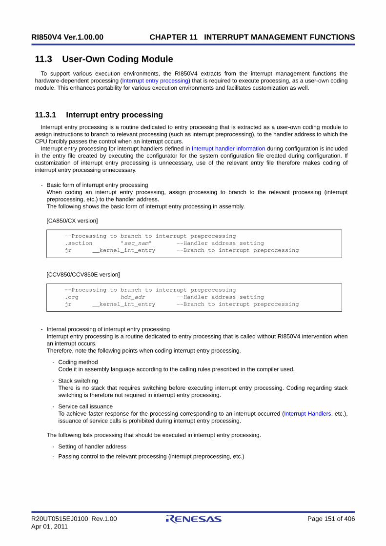
RI850V4 Ver.1.00.00 CHAPTER 11 INTERRUPT MANAGEMENT FUNCTIONS
R20UT0515EJ0100 Rev.1.00 Page 151 of 406Apr 01, 2011
11.3 User-Own Coding Module
To support various execution environments, the RI850V4 extracts from the interrupt management functions thehardware-dependent processing (Interrupt entry processing) that is required to execute processing, as a user-own codingmodule. This enhances portability for various execution environments and facilitates customization as well.
11.3.1 Interrupt entry processing
Interrupt entry processing is a routine dedicated to entry processing that is extracted as a user-own coding module toassign instructions to branch to relevant processing (such as interrupt preprocessing), to the handler address to which theCPU forcibly passes the control when an interrupt occurs.
Interrupt entry processing for interrupt handlers defined in Interrupt handler information during configuration is includedin the entry file created by executing the configurator for the system configuration file created during configuration. Ifcustomization of interrupt entry processing is unnecessary, use of the relevant entry file therefore makes coding ofinterrupt entry processing unnecessary.
- Basic form of interrupt entry processingWhen coding an interrupt entry processing, assign processing to branch to the relevant processing (interruptpreprocessing, etc.) to the handler address.The following shows the basic form of interrupt entry processing in assembly.
[CA850/CX version]
[CCV850/CCV850E version]
- Internal processing of interrupt entry processingInterrupt entry processing is a routine dedicated to entry processing that is called without RI850V4 intervention whenan interrupt occurs.Therefore, note the following points when coding interrupt entry processing.
- Coding methodCode it in assembly language according to the calling rules prescribed in the compiler used.
- Stack switchingThere is no stack that requires switching before executing interrupt entry processing. Coding regarding stackswitching is therefore not required in interrupt entry processing.
- Service call issuanceTo achieve faster response for the processing corresponding to an interrupt occurred (Interrupt Handlers, etc.),issuance of service calls is prohibited during interrupt entry processing.
The following lists processing that should be executed in interrupt entry processing.
- Setting of handler address
- Passing control to the relevant processing (interrupt preprocessing, etc.)
--Processing to branch to interrupt preprocessing .section "sec_nam" --Handler address setting jr __kernel_int_entry --Branch to interrupt preprocessing
--Processing to branch to interrupt preprocessing .org hdr_adr --Handler address setting jr __kernel_int_entry --Branch to interrupt preprocessing
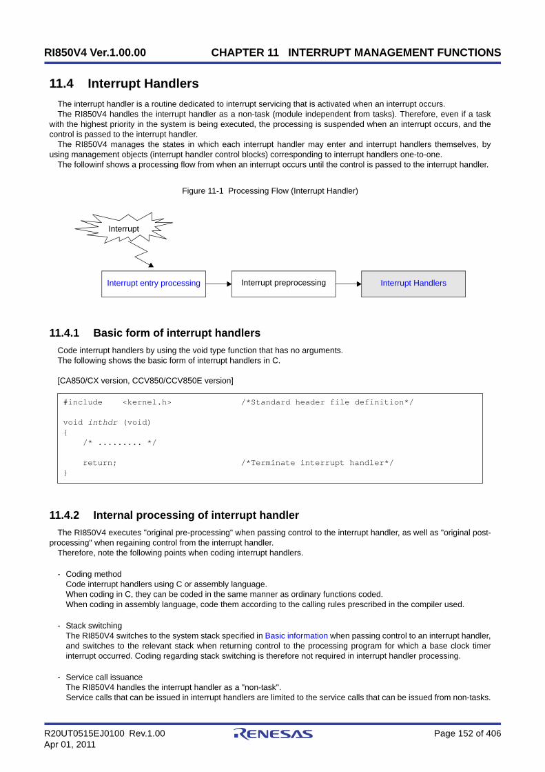
RI850V4 Ver.1.00.00 CHAPTER 11 INTERRUPT MANAGEMENT FUNCTIONS
R20UT0515EJ0100 Rev.1.00 Page 152 of 406Apr 01, 2011
11.4 Interrupt Handlers
The interrupt handler is a routine dedicated to interrupt servicing that is activated when an interrupt occurs.The RI850V4 handles the interrupt handler as a non-task (module independent from tasks). Therefore, even if a task
with the highest priority in the system is being executed, the processing is suspended when an interrupt occurs, and thecontrol is passed to the interrupt handler.
The RI850V4 manages the states in which each interrupt handler may enter and interrupt handlers themselves, byusing management objects (interrupt handler control blocks) corresponding to interrupt handlers one-to-one.
The followinf shows a processing flow from when an interrupt occurs until the control is passed to the interrupt handler.
Figure 11-1 Processing Flow (Interrupt Handler)
11.4.1 Basic form of interrupt handlers
Code interrupt handlers by using the void type function that has no arguments.The following shows the basic form of interrupt handlers in C.
[CA850/CX version, CCV850/CCV850E version]
11.4.2 Internal processing of interrupt handler
The RI850V4 executes "original pre-processing" when passing control to the interrupt handler, as well as "original post-processing" when regaining control from the interrupt handler.
Therefore, note the following points when coding interrupt handlers.
- Coding methodCode interrupt handlers using C or assembly language.When coding in C, they can be coded in the same manner as ordinary functions coded.When coding in assembly language, code them according to the calling rules prescribed in the compiler used.
- Stack switchingThe RI850V4 switches to the system stack specified in Basic information when passing control to an interrupt handler,and switches to the relevant stack when returning control to the processing program for which a base clock timerinterrupt occurred. Coding regarding stack switching is therefore not required in interrupt handler processing.
- Service call issuanceThe RI850V4 handles the interrupt handler as a "non-task".Service calls that can be issued in interrupt handlers are limited to the service calls that can be issued from non-tasks.
#include <kernel.h> /*Standard header file definition*/
void inthdr (void){ /* ......... */
return; /*Terminate interrupt handler*/}
Interrupt
Interrupt entry processing Interrupt HandlersInterrupt preprocessing

RI850V4 Ver.1.00.00 CHAPTER 11 INTERRUPT MANAGEMENT FUNCTIONS
R20UT0515EJ0100 Rev.1.00 Page 153 of 406Apr 01, 2011
Note 1 If a service call (isig_sem, iset_flg, etc.) accompanying dispatch processing (task scheduling processing) isissued in order to quickly complete the processing in the interrupt handler during the interval until theprocessing in the interrupt handler ends, the RI850V4 executes only processing such as queuemanipulation, counter manipulation, etc., and the actual dispatch processing is delayed until a returninstruction is issued by the interrupt handler, upon which the actual dispatch processing is performed inbatch.
Note 2 For details on the valid issuance range of each service call, refer to Table 17-1 to Table 17-14.
- Acknowledgment of maskable interrupts (the ID flag of PSW)When the handler starts, the acknowledgement of maskable interrupts is disabled (PSW ID flag is 1).It is possible to change the maskable interrupt acknowledgement status from inside a process. The changed status isnot passed on when control shifts to the processing program after the task process ends.
Note When the process starts, ISPRn (bit corresponding to priority n of the interrupt) is 1.When the process ends, ISPRn is cleared to 0.
11.4.3 Define interrupt handler
The RI850V4 supports the static registration of interrupt handlers only. They cannot be registered dynamically byissuing a service call from the processing program.
Static interrupt handler registration means defining of interrupt handlers using static API "DEF_INH" in the systemconfiguration file.
For details about the static API "DEF_INH", refer to "18.5.11 Interrupt handler information".
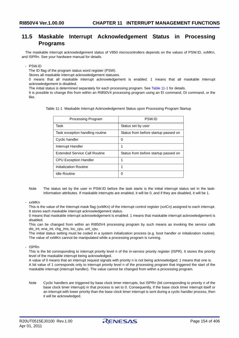
RI850V4 Ver.1.00.00 CHAPTER 11 INTERRUPT MANAGEMENT FUNCTIONS
R20UT0515EJ0100 Rev.1.00 Page 154 of 406Apr 01, 2011
11.5 Maskable Interrupt Acknowledgement Status in ProcessingPrograms
The maskable interrupt acknowledgement status of V850 microcontrollers depends on the values of PSW.ID, xxMKn,and ISPRn. See your hardware manual for details.
- PSW.IDThe ID flag of the program status word register (PSW).Stores all maskable interrupt acknowledgement statuses.0 means that all maskable interrupt acknowledgement is enabled. 1 means that all maskable interruptacknowledgement is disabled.The initial status is determined separately for each processing program. See Table 11-1 for details.It is possible to change this from within an RI850V4 processing program using an EI command, DI command, or thelike.
Table 11-1 Maskable Interrupt Acknowledgement Status upon Processing Program Startup
Note The status set by the user in PSW.ID before the task starts is the initial interrupt status set in the task-information attributes. If maskable interrupts are enabled, it will be 0, and if they are disabled, it will be 1.
- xxMKnThis is the value of the Interrupt mask flag (xxMKn) of the interrupt control register (xxICn) assigned to each interrupt.It stores each maskable interrupt acknowledgement status.0 means that maskable interrupt acknowledgement is enabled. 1 means that maskable interrupt acknowledgement isdisabled.This can be changed from within an RI850V4 processing program by such means as invoking the service callsdis_int, ena_int, chg_ims, loc_cpu, unl_cpu.The initial status setting must be coded in a system initialization process (e.g. boot handler or initialization routine).The value of xxMKn cannot be manipulated while a processing program is running.
- ISPRnThis is the bit corresponding to interrupt priority level n of the in-service priority register (ISPR). It stores the prioritylevel of the maskable interrupt being acknowledged.A value of 0 means that an interrupt request signals with priority n is not being acknowledged; 1 means that one is.A bit value of 1 corresponds only to interrupt priority level n of the processing program that triggered the start of themaskable interrupt (interrupt handler). The value cannot be changed from within a processing program.
Note Cyclic handlers are triggered by base clock timer interrupts, but ISPRn (bit corresponding to priority n of thebase clock timer interrupt) in that process is set to 0. Consequently, if the base clock timer interrupt itself oran interrupt with lower priority than the base clock timer interrupt is sent during a cyclic handler process, thenit will be acknowledged.
Processing Program PSW.ID
Task Status set by user
Task exception handling routine Status from before startup passed on
Cyclic handler 0
Interrupt Handler 1
Extended Service Call Routine Status from before startup passed on
CPU Exception Handler 1
Initialization Routine 1
Idle Routine 0

RI850V4 Ver.1.00.00 CHAPTER 11 INTERRUPT MANAGEMENT FUNCTIONS
R20UT0515EJ0100 Rev.1.00 Page 155 of 406Apr 01, 2011
11.6 Disable Interrupt
Acknowledgment of maskable interrupts is disabled by issuing the following service call from the processing program.
- dis_intThis service call disables acknowledgment of maskable interrupts corresponding to the exception code specified byparameter intno.If a maskable interrupt corresponding to the exception code specified by parameter intno occurs from when thisservice call is issued until ena_int is issued, the RI850V4 delays branching to the relevant interrupt servicing (interrupthandler) until ena_int is issued.The following shows a processing flow when acknowledgment of maskable interrupts is disabled.
Figure 11-2 Disabling Acknowledgment of Maskable Interrupt
The following describes an example for coding this service call.
[CA850/CX version]
Note 1 The processing performed by this service call depends on the user execution environment, so it is extractedas a target-dependent module and provided as sample source files.In sample source files, manipulation for the interrupt control register xxICn and the interrupt mask flag
#include <kernel.h> /*Standard header file definition*/
#pragma rtos_task task /*#pragma directive definition*/
void task (VP_INT exinf){ INTNO intno = 0x80; /*Declares and initializes variable*/
/* ......... */
dis_int (intno); /*Disable interrupt*/
/* ......... */ /*Acknowledgment disabled*/
ena_int (intno); /*Enable interrupt*/
/* ......... */ /*Acknowledgment enabled*/}
Disable Interrupt
Enable Interrupt
Task
return
Interrupt
Interrupt handler
Delayed period
RI850V4 Ver.1.00.00 CHAPTER 11 INTERRUPT MANAGEMENT FUNCTIONS
R20UT0515EJ0100 Rev.1.00 Page 156 of 406Apr 01, 2011
xxMKn of the interrupt mask register IMRm is coded as processing to disable acknowledgment of maskableinterrupt.
Note 2 This service call does not perform queuing of disable requests. If this service call has already been issuedand acknowledgment of the corresponding maskable interrupt has been disabled, therefore, no processingis performed but it is not handled as an error.
Note 3 The RI850V4 realizes the TIME MANAGEMENT FUNCTIONS by using base clock timer interrupts thatoccur at constant intervals. If acknowledgment of the relevant base clock timer interrupt is disabled byissuing this service call, the TIME MANAGEMENT FUNCTIONS may no longer operate normally.

RI850V4 Ver.1.00.00 CHAPTER 11 INTERRUPT MANAGEMENT FUNCTIONS
R20UT0515EJ0100 Rev.1.00 Page 157 of 406Apr 01, 2011
11.7 Enable Interrupt
Acknowledgment of maskable interrupts is enabled by issuing the following service call from the processing program.
- ena_intThis service call enables acknowledgment of maskable interrupts corresponding to the exception code specified byparameter intno.If a maskable interrupt corresponding to the exception code specified by parameter intno occurs from when dis_int isissued until this service call is issued, the RI850V4 delays branching to the relevant interrupt servicing (interrupthandler) until this service call is issued.The following shows a processing flow when acknowledgment of maskable interrupts is enabled.
Figure 11-3 Enabling Acknowledgment of Maskable Interrupt
The following describes an example for coding this service call.
[CA850/CX version]
Note 1 The processing performed by this service call depends on the user execution environment, so it is extractedas a target-dependent module and provided as sample source files.In sample source files, manipulation for the interrupt control register xxICn and the interrupt mask flag
#include <kernel.h> /*Standard header file definition*/
#pragma rtos_task task /*#pragma directive definition*/
void task (VP_INT exinf){ INTNO intno = 0x80; /*Declares and initializes variable*/
/* ......... */
dis_int (intno); /*Disable interrupt*/
/* ......... */ /*Acknowledgment disabled*/
ena_int (intno); /*Enable interrupt*/
/* ......... */ /*Acknowledgment enabled*/}
Disable Interrupt
Enable Interrupt
Task
return
Interrupt
Interrupt handler
Delayed period
RI850V4 Ver.1.00.00 CHAPTER 11 INTERRUPT MANAGEMENT FUNCTIONS
R20UT0515EJ0100 Rev.1.00 Page 158 of 406Apr 01, 2011
xxMKn of the interrupt mask register IMRm is coded as processing to enable acknowledgment of maskableinterrupt.
Note 2 This service call does not perform queuing of enable requests. If this service call has already been issuedand acknowledgment of the corresponding maskable interrupt has been enabled, therefore, no processing isperformed but it is not handled as an error.
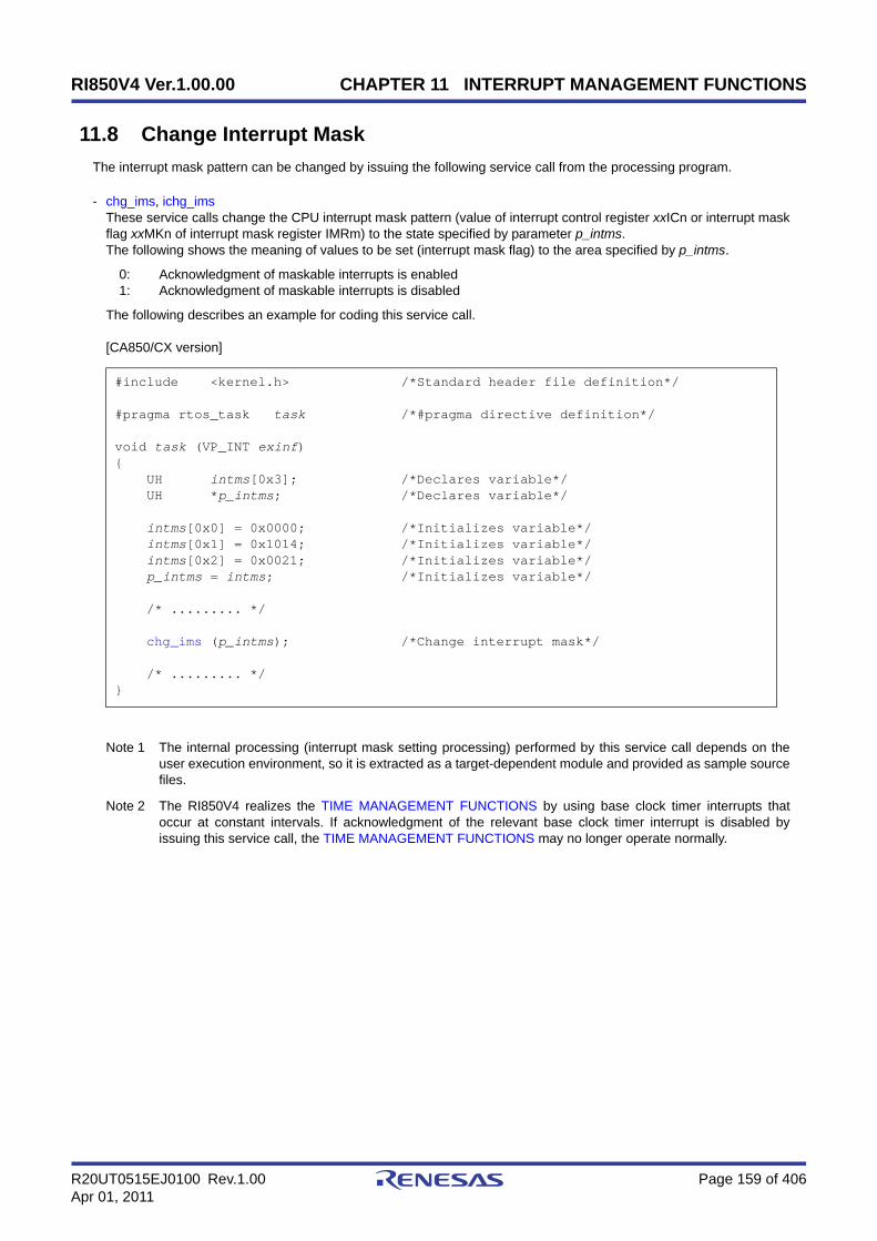
RI850V4 Ver.1.00.00 CHAPTER 11 INTERRUPT MANAGEMENT FUNCTIONS
R20UT0515EJ0100 Rev.1.00 Page 159 of 406Apr 01, 2011
11.8 Change Interrupt Mask
The interrupt mask pattern can be changed by issuing the following service call from the processing program.
- chg_ims, ichg_imsThese service calls change the CPU interrupt mask pattern (value of interrupt control register xxICn or interrupt maskflag xxMKn of interrupt mask register IMRm) to the state specified by parameter p_intms.The following shows the meaning of values to be set (interrupt mask flag) to the area specified by p_intms.
0: Acknowledgment of maskable interrupts is enabled1: Acknowledgment of maskable interrupts is disabled
The following describes an example for coding this service call.
[CA850/CX version]
Note 1 The internal processing (interrupt mask setting processing) performed by this service call depends on theuser execution environment, so it is extracted as a target-dependent module and provided as sample sourcefiles.
Note 2 The RI850V4 realizes the TIME MANAGEMENT FUNCTIONS by using base clock timer interrupts thatoccur at constant intervals. If acknowledgment of the relevant base clock timer interrupt is disabled byissuing this service call, the TIME MANAGEMENT FUNCTIONS may no longer operate normally.
#include <kernel.h> /*Standard header file definition*/
#pragma rtos_task task /*#pragma directive definition*/
void task (VP_INT exinf){ UH intms[0x3]; /*Declares variable*/ UH *p_intms; /*Declares variable*/
intms[0x0] = 0x0000; /*Initializes variable*/ intms[0x1] = 0x1014; /*Initializes variable*/ intms[0x2] = 0x0021; /*Initializes variable*/ p_intms = intms; /*Initializes variable*/
/* ......... */
chg_ims (p_intms); /*Change interrupt mask*/
/* ......... */}

RI850V4 Ver.1.00.00 CHAPTER 11 INTERRUPT MANAGEMENT FUNCTIONS
R20UT0515EJ0100 Rev.1.00 Page 160 of 406Apr 01, 2011
11.9 Reference Interrupt Mask
The interrupt mask pattern can be referenced by issuing the following service call from the processing program.
- get_ims, iget_imsThese service calls store the CPU interrupt mask pattern (value of interrupt control register xxICn or interrupt maskflag xxMKn of interrupt mask register IMRm) into the area specified by parameter p_intms.The following shows the meaning of values to be stored (interrupt mask flag) into the area specified by p_intms.
0: Acknowledgment of maskable interrupts is enabled1: Acknowledgment of maskable interrupts is disabled
The following describes an example for coding this service call.
[CA850/CX version]
Note The internal processing (interrupt mask acquire processing) performed by this service call depends on theuser execution environment, so it is extracted as a target-dependent module and provided as sample sourcefiles.
#include <kernel.h> /*Standard header file definition*/
#pragma rtos_task task /*#pragma directive definition*/
void task (VP_INT exinf){ UH p_intms[0x3]; /*Declares variable*/
/* ......... */
get_ims (p_intms); /*Reference interrupt mask*/
/* ......... */}

RI850V4 Ver.1.00.00 CHAPTER 11 INTERRUPT MANAGEMENT FUNCTIONS
R20UT0515EJ0100 Rev.1.00 Page 161 of 406Apr 01, 2011
11.10 Non-Maskable Interrupts
Non-maskable interrupts are not subject to interrupt priority orders, so they are acknowledged prior to all kinds ofidentifiable interrupts. In addition, they are acknowledged even when the interrupts are disabled (by setting the ID flag ofthe program status word PSW to 1) in the CPU. That is, non-maskable interrupts are acknowledged even if the RI850V4status is moved to the CPU locked state or maskable interrupt disabled state.
Note Interrupt handlers for non-maskable interrupts are exclude from the management targets of the RI850V4.Issuance of service calls is therefore prohibited in interrupt handlers for non-maskable interrupts.
11.11 Base Clock Timer Interrupts
The RI850V4 realizes the TIME MANAGEMENT FUNCTIONS by using base clock timer interrupts that occur atconstant intervals.
If a base clock timer interrupt occurs, The RI850V4's time management interrupt handler is activated and executes time-related processing (system time update, delayed wakeup/timeout of task, cyclic handler activation, etc.).
Note If acknowledgment of the relevant base clock timer interrupt is disabled by issuing loc_cpu, iloc_cpu or dis_int,the TIME MANAGEMENT FUNCTIONS may no longer operate normally.
11.12 Multiple Interrupts
In the RI850V4, occurrence of an interrupt in an interrupt handler is called "multiple interrupts".Execution of interrupt handler is started in the interrupt disabled state (the ID flag of the program status word PSW is set
to 1). To generate multiple interrupts, processing to cancel the interrupt disabled state (such as issuing of EI instruction)must therefore be coded in the interrupt handler explicitly.
The following shows a processing flow when multiple interrupts occur.
Figure 11-4 Multiple Interrupts
Task Interrupt handler A
return
Interrupt handler B
return
Interrupt
Interrupt
Calling EI instruction
Calling DI instruction

RI850V4 Ver.1.00.00 CHAPTER 12 SERVICE CALL MANAGEMENT FUNCTIONS
R20UT0515EJ0100 Rev.1.00 Page 162 of 406Apr 01, 2011
CHAPTER 12 SERVICE CALL MANAGEMENT FUNC-TIONS
This chapter describes the service call management functions performed by the RI850V4.
12.1 Outline
The RI850V4's service call management function provides the function for manipulating the extended service callroutine status, such as registering and calling of extended service call routines.
12.2 Extended Service Call Routines
This is a routine to which user-defined functions are registered in the RI850V4, and will never be executed unless it iscalled explicitly, using service calls provided by the RI850V4.
The RI850V4 positions extended service call routines as extensions of the processing program that called the extendedservice call routine.
The RI850V4 manages interrupt handlers themselves, by using management objects (extended service call routinecontrol blocks) corresponding to extended service call routines one-to-one.
12.2.1 Basic form extended service call routines
Code extended service call routines by using the ER_UINT type argument that has three VP_INT type arguments.Transferred data specified when a call request (cal_svc or ical_svc) is issued is set to arguments par1, par2, and par3.The following shows the basic form of extended service call routines in C.
[CA850/CX version, CCV850/CCV850E version]
#include <kernel.h> /*Standard header file definition*/
ER_UINT svcrtn (VP_INT par1, VP_INT par2, VP_INT par3){ /* ......... */
return (ER_UINT ercd); /*Terminate extended service call routine*/}

RI850V4 Ver.1.00.00 CHAPTER 12 SERVICE CALL MANAGEMENT FUNCTIONS
R20UT0515EJ0100 Rev.1.00 Page 163 of 406Apr 01, 2011
12.2.2 Internal processing of extended service call routine
The RI850V4 executes the original extended service call routine pre-processing when passing control from theprocessing program that issued a call request to an extended service call routine, as well as the original extended servicecall routine post-processing when returning control from the extended service call routine to the processing program.
Therefore, note the following points when coding extended service call routines.
- Coding methodCode extended service call routines using C or assembly language.When coding in C, they can be coded in the same manner as ordinary functions coded.When coding in assembly language, code them according to the calling rules prescribed in the compiler used.
- Stack switchingThe RI850V4 positions extended service call routines as extensions of the processing program that called theextended service call routine. When passing control to an extended service call routine, stack switching processing istherefore not performed.
- Service call issuanceThe RI850V4 positions extended service call routines as extensions of the processing program that called theextended service call routine. Service calls that can be issued in extended service call routines depend on the type(task or non-task) of the processing program that called the extended service call routine.
Note For details on the valid issuance range of each service call, refer to Table 17-1 to Table 17-14.
- Acknowledgment of maskable interrupts (the ID flag of PSW)The maskable interrupt acknowledgement status depends on the processing program that called the extendedservice call routine.Upon startup, the maskable interrupt acknowledgement status is inherited from the processing program that calledthe extended service call routine.It is possible to change the maskable interrupt acknowledgement status from inside a process. After the processends, the changed status is maintained when control returns to the processing program that called the extendedservice call routine.
12.3 Define Extended Service Call Routine
The RI850V4 supports the static registration of extended service call routines only. They cannot be registereddynamically by issuing a service call from the processing program.
Static extended service call routine registration means defining of extended service call routines using static API"CRE_SVC" in the system configuration file.
For details about the static API "DEF_SVC", refer to "18.5.13 Extended service call routine information".

RI850V4 Ver.1.00.00 CHAPTER 12 SERVICE CALL MANAGEMENT FUNCTIONS
R20UT0515EJ0100 Rev.1.00 Page 164 of 406Apr 01, 2011
12.4 Invoke Extended Service Call Routine
Extended service call routines can be called by issuing the following service call from the processing program.
- cal_svc, ical_svcThese service calls call the extended service call routine specified by parameter fncd.The following describes an example for coding this service call.
[CA850/CX version]
Note Extended service call routines that can be called using this service call are the routines whose transferreddata total is less than four.
#include <kernel.h> /*Standard header file definition*/
#pragma rtos_task task /*#pragma directive definition*/
void task (VP_INT exinf){ ER_UINT ercd; /*Declares variable*/ FN fncd = 1; /*Declares and initializes variable*/ VP_INT par1 = 123; /*Declares and initializes variable*/ VP_INT par2 = 456; /*Declares and initializes variable*/ VP_INT par3 = 789; /*Declares and initializes variable*/
/* ......... */
/*Invoke extended service call routine*/ ercd = cal_svc (fncd, par1, par2, par3);
if (ercd != E_RSFN) { /* ......... */ /*Normal termination processing*/ }
/* ......... */}

RI850V4 Ver.1.00.00
R20UT0515EJ0100 Rev.1.00 Page 165 of 406Apr 01, 2011
CHAPTER 13 SYSTEM CONFIGURATION MANAGEMENTFUNCTIONS
CHAPTER 13 SYSTEM CONFIGURATION MANAGE-MENT FUNCTIONS
This chapter describes the system configuration management functions performed by the RI850V4.
13.1 Outline
The RI850V4 provides as system configuration management functions related to the CPU exception handlers activatedwhen a CPU exception is occurred.
13.2 User-Own Coding Module
To support various execution environments, the RI850V4 extracts from the system management functions thehardware-dependent processing (CPU exception entry processing, Initialization routine) that is required to executeprocessing, as a user-own coding module. This enhances portability for various execution environments and facilitatescustomization as well.
13.2.1 CPU exception entry processing
A routine dedicated to entry processing that is extracted as a user-own coding module to assign instructions to branchto relevant processing (such as CPU exception preprocessing or Boot processing), to the handler address to which theCPU forcibly passes the control when a CPU exception occurs.
CPU exception handling for CPU exception handlers defined in CPU exception handler information during configurationis included in the entry file created by executing the configurator for the system configuration file created duringconfiguration. If customization of CPU exception entry processing is unnecessary, use of the relevant entry file thereforemakes coding of CPU exception entry processing unnecessary.
- Basic form of CPU exception entry processingWhen coding a CPU exception entry processing, assign processing to branch to the relevant processing (CPUexception preprocessing, Boot processing, etc.) to the handler address.The following shows the basic form of CPU exception entry processing in assembly.
[CA850/CX version]
[CCV850/CCV850E version]
-- Processing braches to CPU exception preprocessing .section "sec_nam" --Handler address setting jr __kernel_exc_entry --Branch to CPU exception preprocessing
--Processing branches to Boot processing .section "sec_nam" --Handler address setting jr __boot --Branch to Boot processing
-- Processing braches to CPU exception preprocessing .org hdr_adr --Handler address setting jr __kernel_exc_entry --Branch to CPU exception preprocessing
--Processing branches to Boot processing .org hdr_adr --Handler address setting jr __boot --Branch to Boot processing

RI850V4 Ver.1.00.00
R20UT0515EJ0100 Rev.1.00 Page 166 of 406Apr 01, 2011
CHAPTER 13 SYSTEM CONFIGURATION MANAGEMENTFUNCTIONS
- Internal processing of CPU exception entry processingCPU exception entry processing is a routine dedicated to entry processing that is called without RI850V4 interventionwhen a CPU exception occurs.Therefore, note the following points when coding CPU exception entry processing.
- Coding methodCode it in assembly language according to the calling rules prescribed in the compiler used.
- Stack switchingThere is no stack that requires switching before executing CPU exception entry processing. Coding regardingstack switching is therefore not required in CPU exception entry processing.
- Service call issuanceTo achieve faster response for the processing corresponding to a CPU exception occurred (Boot processing,CPU Exception Handlers, etc.), issuance of service calls is prohibited during CPU exception entry processing.
The following lists processing that should be executed in CPU exception entry processing.
- Setting of handler address
- External label declaration
- Passing control to the relevant processing (Boot processing, CPU Exception Handlers, etc.)
13.2.2 Initialization routine
The initialization routine is a routine dedicated to initialization processing that is extracted as a user-own coding moduleto initialize the hardware dependent on the user execution environment (such as the peripheral controller), and is calledfrom the Kernel Initialization Module.
The RI850V4 manages the states in which each initialization routine may enter and initialization routines themselves, byusing management objects (initialization routine control blocks) corresponding to initialization routines one-to-one.
The following shows a processing flow from when a reset interrupt occurs until the control is passed to the task.
Figure 13-1 Processing Flow (Initialization Routine)
- Basic form of initialization routinesCode initialization routines by using the void type function that has one VP_INT type argument.Extended information specified in Initialization routine information is set to argument exinf.The following shows the basic form of initialization routine in C.
Reset interrupt
Boot processing
Kernel Initialization Module
Initialization routine
SCHEDULER Tasks
CPU exception entry processing
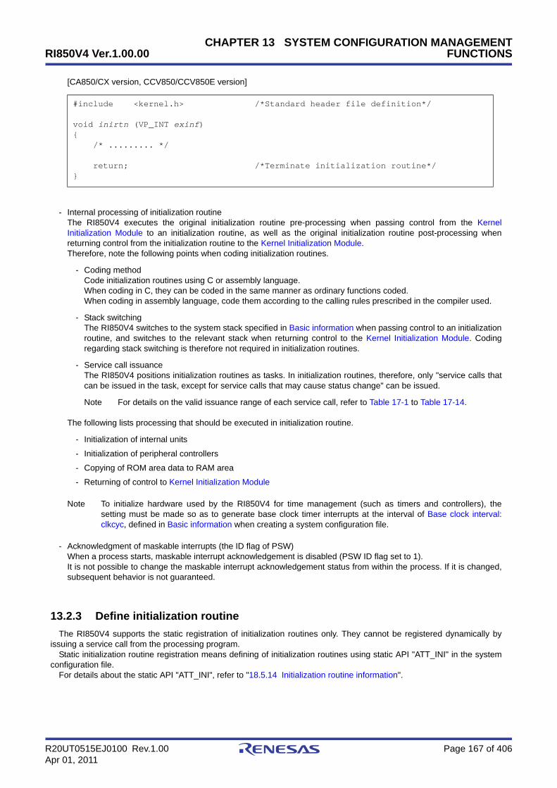
RI850V4 Ver.1.00.00
R20UT0515EJ0100 Rev.1.00 Page 167 of 406Apr 01, 2011
CHAPTER 13 SYSTEM CONFIGURATION MANAGEMENTFUNCTIONS
[CA850/CX version, CCV850/CCV850E version]
- Internal processing of initialization routineThe RI850V4 executes the original initialization routine pre-processing when passing control from the KernelInitialization Module to an initialization routine, as well as the original initialization routine post-processing whenreturning control from the initialization routine to the Kernel Initialization Module.Therefore, note the following points when coding initialization routines.
- Coding methodCode initialization routines using C or assembly language.When coding in C, they can be coded in the same manner as ordinary functions coded.When coding in assembly language, code them according to the calling rules prescribed in the compiler used.
- Stack switchingThe RI850V4 switches to the system stack specified in Basic information when passing control to an initializationroutine, and switches to the relevant stack when returning control to the Kernel Initialization Module. Codingregarding stack switching is therefore not required in initialization routines.
- Service call issuanceThe RI850V4 positions initialization routines as tasks. In initialization routines, therefore, only "service calls thatcan be issued in the task, except for service calls that may cause status change" can be issued.
Note For details on the valid issuance range of each service call, refer to Table 17-1 to Table 17-14.
The following lists processing that should be executed in initialization routine.
- Initialization of internal units
- Initialization of peripheral controllers
- Copying of ROM area data to RAM area
- Returning of control to Kernel Initialization Module
Note To initialize hardware used by the RI850V4 for time management (such as timers and controllers), thesetting must be made so as to generate base clock timer interrupts at the interval of Base clock interval:clkcyc, defined in Basic information when creating a system configuration file.
- Acknowledgment of maskable interrupts (the ID flag of PSW)When a process starts, maskable interrupt acknowledgement is disabled (PSW ID flag set to 1).It is not possible to change the maskable interrupt acknowledgement status from within the process. If it is changed,subsequent behavior is not guaranteed.
13.2.3 Define initialization routine
The RI850V4 supports the static registration of initialization routines only. They cannot be registered dynamically byissuing a service call from the processing program.
Static initialization routine registration means defining of initialization routines using static API "ATT_INI" in the systemconfiguration file.
For details about the static API "ATT_INI", refer to "18.5.14 Initialization routine information".
#include <kernel.h> /*Standard header file definition*/
void inirtn (VP_INT exinf){ /* ......... */
return; /*Terminate initialization routine*/}

RI850V4 Ver.1.00.00
R20UT0515EJ0100 Rev.1.00 Page 168 of 406Apr 01, 2011
CHAPTER 13 SYSTEM CONFIGURATION MANAGEMENTFUNCTIONS
13.3 CPU Exception Handlers
The RI850V4 handles the CPU exception handler as a non-task (module independent from tasks). Therefore, even if atask with the highest priority in the system is being executed, the processing is suspended when a CPU exception occurs,and the control is passed to the CPU exception handler.
The RI850V4 manages the states in which each CPU exception handler may enter and CPU exception handlersthemselves, by using management objects (CPU exception handler control blocks) corresponding to CPU exceptionhandlers one-to-one.
The following shows a processing from when a CPU exception occurs until the control is passed to a CPU exceptionhandler.
Figure 13-2 Processing Flow (CPU Exception Handler)
13.3.1 Basic form of CPU exception handlers
Code CPU exception handlers by using the void type function that has no arguments.The following shows the basic form of CPU exception handlers in C.
[CA850/CX version, CCV850/CCV850E version]
13.3.2 Internal processing of CPU exception handler
The RI850V4 executes "original pre-processing" when passing control to the CPU exception handler, as well as "originalpost-processing" when regaining control from the CPU exception handler.
Therefore, note the following points when coding CPU exception handlers.
- Coding methodCode CPU exception handlers using C or assembly language.When coding in C, they can be coded in the same manner as ordinary functions coded.When coding in assembly language, code them according to the calling rules prescribed in the compiler used.
- Stack switchingThe RI850V4 switches to the system stack specified in Basic information when passing control to a CPU exceptionhandler, and switches to the relevant stack when returning control to the processing program for which a CPUexception occurred. Coding regarding stack switching is therefore not required in CPU exception handler processing.
- Service call issuanceThe RI850V4 handles the CPU exception handler as a "non-task".
#include <kernel.h> /*Standard header file definition*/
void exchdr (void){ /* ......... */
return; /*Terminate CPU exception handler*/}
CPU exception
CPU Exception HandlersCPU exception entry processing CPU exception preprocessing

RI850V4 Ver.1.00.00
R20UT0515EJ0100 Rev.1.00 Page 169 of 406Apr 01, 2011
CHAPTER 13 SYSTEM CONFIGURATION MANAGEMENTFUNCTIONS
Service calls that can be issued in CPU exception handlers are limited to the service calls that can be issued fromnon-tasks.
Note 1 If a service call (isig_sem, iset_flg, etc.) accompanying dispatch processing (task scheduling processing) isissued in order to quickly complete the processing in the CPU exception handler during the interval until theprocessing in the CPU exception handler ends, the RI850V4 executes only processing such as queuemanipulation and the actual dispatch processing is delayed until a return instruction is issued, upon whichthe actual dispatch processing is performed in batch.The RI850V4 supports the static registration of CPU exception handlers only. They cannot be registereddynamically by issuing a service call from the processing program.Static CPU exception handler registration means defining of CPU exception handlers using static API"DEF_EXC" in the system configuration file.
Note 2 For details on the valid issuance range of each service call, refer to Table 17-1 to Table 17-14.
- Acknowledgment of maskabel interrupts (the ID flag of PSW)When the handler starts, the acknowledgement of maskable interrupts is disabled (PSW ID flag is 1).It is not possible to change the maskable interrupt acknowledgement status from inside a process.
13.4 Define CPU Exception Handler
Static ready queue creation means defining of ready queues using static API "CRE_PRI" in the system configurationfile.
For details about the static API "DEF_EXC", refer to "18.5.12 CPU exception handler information".
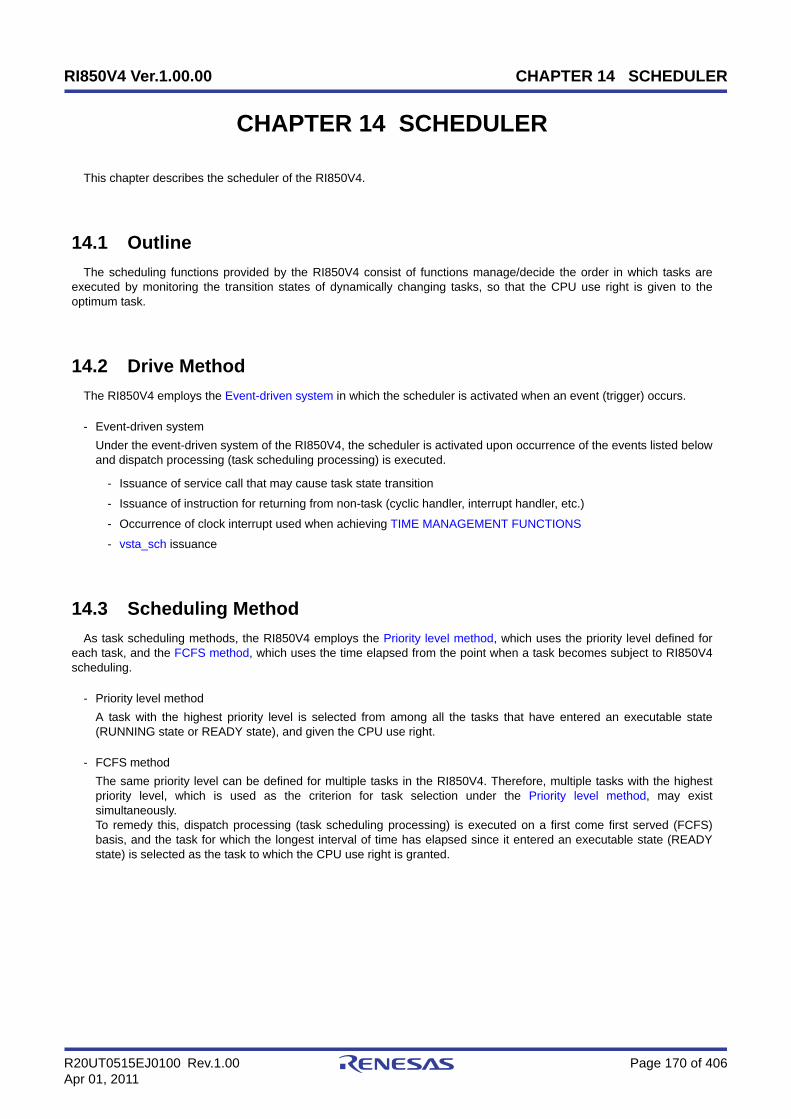
RI850V4 Ver.1.00.00 CHAPTER 14 SCHEDULER
R20UT0515EJ0100 Rev.1.00 Page 170 of 406Apr 01, 2011
CHAPTER 14 SCHEDULER
This chapter describes the scheduler of the RI850V4.
14.1 Outline
The scheduling functions provided by the RI850V4 consist of functions manage/decide the order in which tasks areexecuted by monitoring the transition states of dynamically changing tasks, so that the CPU use right is given to theoptimum task.
14.2 Drive Method
The RI850V4 employs the Event-driven system in which the scheduler is activated when an event (trigger) occurs.
- Event-driven systemUnder the event-driven system of the RI850V4, the scheduler is activated upon occurrence of the events listed belowand dispatch processing (task scheduling processing) is executed.
- Issuance of service call that may cause task state transition
- Issuance of instruction for returning from non-task (cyclic handler, interrupt handler, etc.)
- Occurrence of clock interrupt used when achieving TIME MANAGEMENT FUNCTIONS
- vsta_sch issuance
14.3 Scheduling Method
As task scheduling methods, the RI850V4 employs the Priority level method, which uses the priority level defined foreach task, and the FCFS method, which uses the time elapsed from the point when a task becomes subject to RI850V4scheduling.
- Priority level methodA task with the highest priority level is selected from among all the tasks that have entered an executable state(RUNNING state or READY state), and given the CPU use right.
- FCFS methodThe same priority level can be defined for multiple tasks in the RI850V4. Therefore, multiple tasks with the highestpriority level, which is used as the criterion for task selection under the Priority level method, may existsimultaneously.To remedy this, dispatch processing (task scheduling processing) is executed on a first come first served (FCFS)basis, and the task for which the longest interval of time has elapsed since it entered an executable state (READYstate) is selected as the task to which the CPU use right is granted.
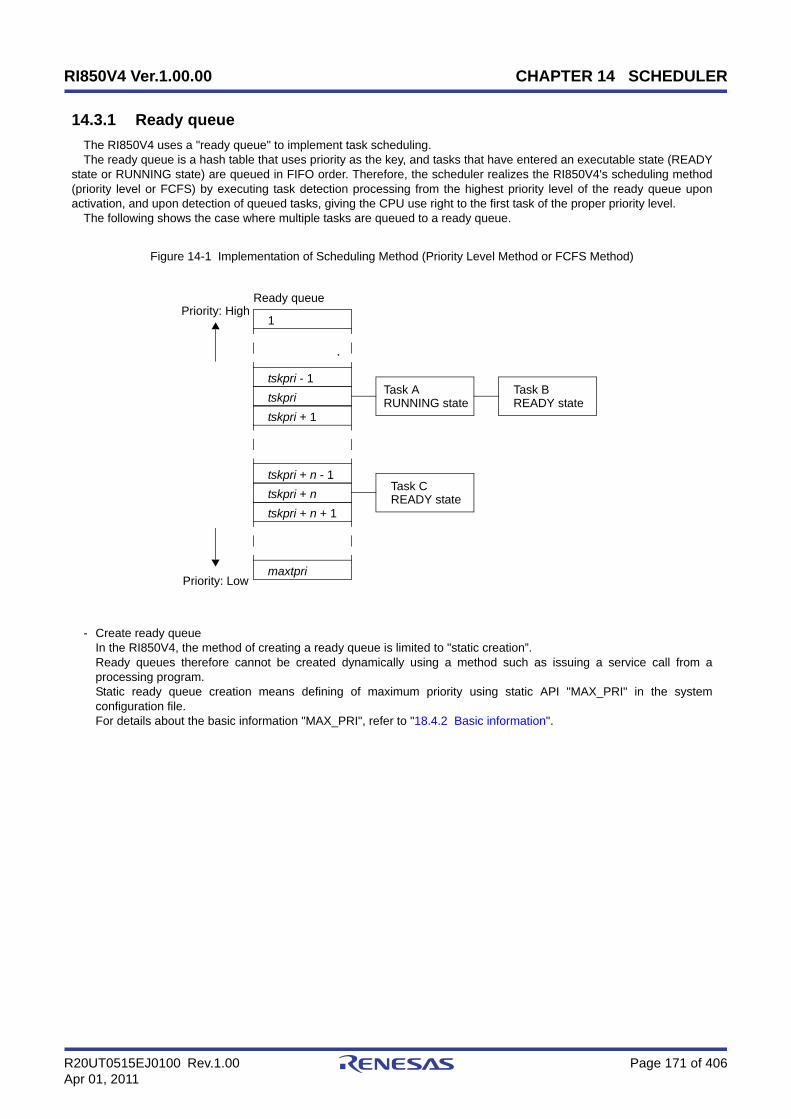
RI850V4 Ver.1.00.00 CHAPTER 14 SCHEDULER
R20UT0515EJ0100 Rev.1.00 Page 171 of 406Apr 01, 2011
14.3.1 Ready queue
The RI850V4 uses a "ready queue" to implement task scheduling.The ready queue is a hash table that uses priority as the key, and tasks that have entered an executable state (READY
state or RUNNING state) are queued in FIFO order. Therefore, the scheduler realizes the RI850V4's scheduling method(priority level or FCFS) by executing task detection processing from the highest priority level of the ready queue uponactivation, and upon detection of queued tasks, giving the CPU use right to the first task of the proper priority level.
The following shows the case where multiple tasks are queued to a ready queue.
Figure 14-1 Implementation of Scheduling Method (Priority Level Method or FCFS Method)
- Create ready queueIn the RI850V4, the method of creating a ready queue is limited to "static creation”.Ready queues therefore cannot be created dynamically using a method such as issuing a service call from aprocessing program.Static ready queue creation means defining of maximum priority using static API "MAX_PRI" in the systemconfiguration file.For details about the basic information "MAX_PRI", refer to "18.4.2 Basic information".
Priority: High
Task ARUNNING state
Task BREADY state
Task CREADY state
Ready queue
Priority: Low
tskpri
tskpri + 1
tskpri - 1
tskpri + ntskpri + n + 1
tskpri + n - 1
1
maxtpri
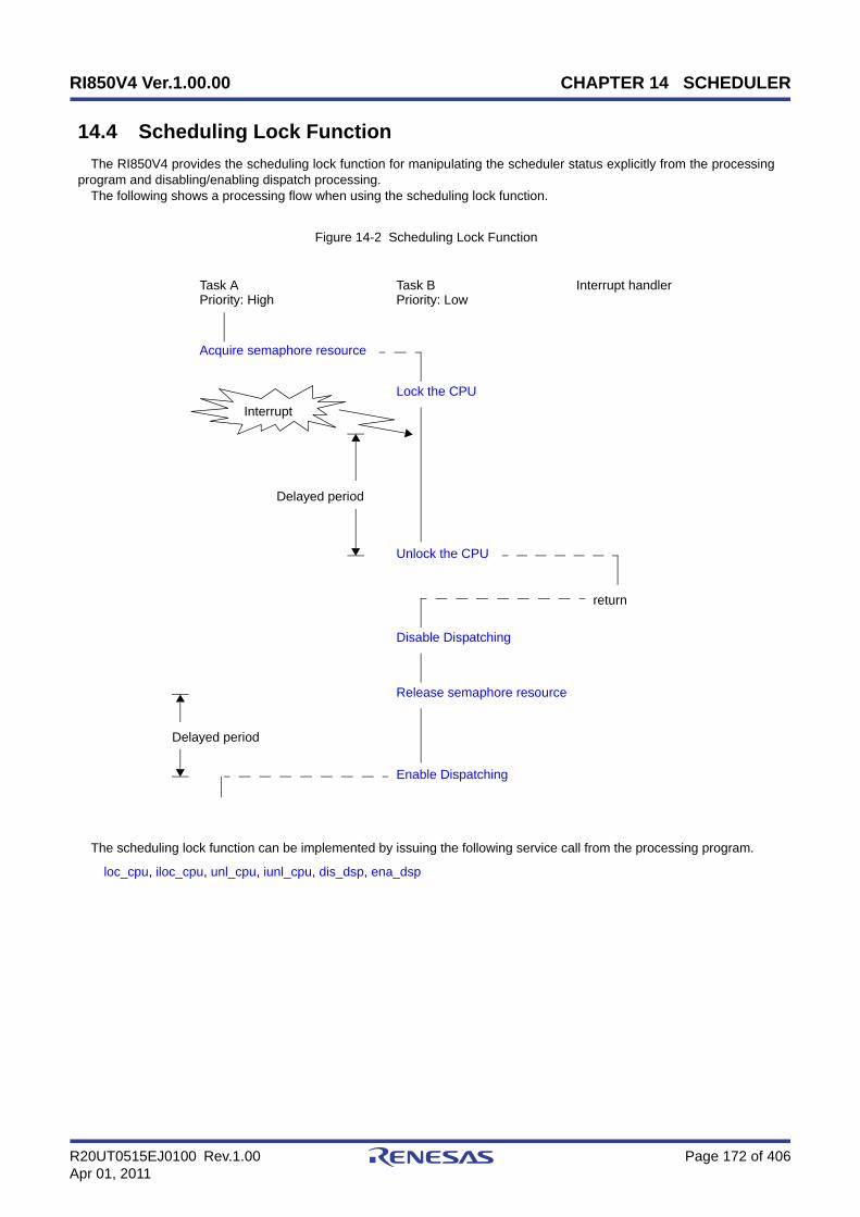
RI850V4 Ver.1.00.00 CHAPTER 14 SCHEDULER
R20UT0515EJ0100 Rev.1.00 Page 172 of 406Apr 01, 2011
14.4 Scheduling Lock Function
The RI850V4 provides the scheduling lock function for manipulating the scheduler status explicitly from the processingprogram and disabling/enabling dispatch processing.
The following shows a processing flow when using the scheduling lock function.
Figure 14-2 Scheduling Lock Function
The scheduling lock function can be implemented by issuing the following service call from the processing program.
loc_cpu, iloc_cpu, unl_cpu, iunl_cpu, dis_dsp, ena_dsp
Task APriority: High
Task BPriority: Low
return
Interrupt
Interrupt handler
Delayed period
Lock the CPU
Unlock the CPU
Delayed period
Release semaphore resource
Disable Dispatching
Enable Dispatching
Acquire semaphore resource

RI850V4 Ver.1.00.00 CHAPTER 14 SCHEDULER
R20UT0515EJ0100 Rev.1.00 Page 173 of 406Apr 01, 2011
14.5 Idle Routine
The idle routine is a routine dedicated to idle processing that is extracted as a user-own coding module to utilize thestandby function provided by the CPU (to achieve the low-power consumption system), and is called from the schedulerwhen there no longer remains a task subject to scheduling by the RI850V4 (task in the RUNNING or READY state) in thesystem.
The RI850V4 manages the states in which each idle routine may enter and idle routines themselves, by usingmanagement objects (idle routine control blocks) corresponding to idle routines one-to-one.
14.5.1 Basic form of idle routine
Code idle routines by using the void type function that has no arguments.The following shows the basic form of idle routine in C.
[CA850/CX version, CCV850/CCV850E version]
14.5.2 Internal processong of idle routine
The RI850V4 executes "original pre-processing" when passing control to the idle routine, as well as "original post-processing" when regaining control from the idle routine.
Therefore, note the following points when coding idle routines.
- Coding methodCode idle routines using C or assembly language.When coding in C, they can be coded in the same manner as ordinary functions coded.When coding in assembly language, code them according to the calling rules prescribed in the compiler used.
- Stack switchingThe RI850V4 switches to the system stack specified in Basic information when passing control to an idle routine.Coding regarding stack switching is therefore not required in idle routines.
- Service call issuanceThe RI850V4 prohibits issuance of service calls in idle routines.
- Acknowledgment of maskable interrupts (the ID flag of PSW)When a process starts, maskable interrupt acknowledgement is enabled (PSW ID flag set to 0).It is possible to change the maskable interrupt acknowledgement status from within the process.After the process terminates, the maskable interrupt acknowledgement status is not inherited by subsequentprocesses.
- Processing loopAfter the idle routine's process terminates, the routine is resumed from the beginning. When the routine is resumed, itdoes not inherit the status of the previous idle routine (stack pointer and maskable interrupt acknowledgement status).
The following lists processing that should be executed in idle routines.
- Effective use of standby function provided by the CPU
#include <kernel.h> /*Standard header file definition*/
void idlrtn (void){ /* ......... */
return; /*Terminate idle routine*/}

RI850V4 Ver.1.00.00 CHAPTER 14 SCHEDULER
R20UT0515EJ0100 Rev.1.00 Page 174 of 406Apr 01, 2011
14.6 Define Idle Routine
The RI850V4 supports the static registration of idle routines only. They cannot be registered dynamically by issuing aservice call from the processing program.
Static idle routine registration means defining of idle routines using static API "VATT_IDL" in the system configurationfile.
For details about the static API "VATT_IDL", refer to "18.5.15 Idle routine information".
Note If Idle routine information is not defined, the default idle routine (function name: _kernel_default_idlrtn) isregistered during configuration.
14.7 Scheduling in Non-Tasks
If a service call (isig_sem, iset_flg, etc.) accompanying dispatch processing (task scheduling processing) is issued inorder to quickly complete the processing in the non-task (cyclic handler, interrupt handler, etc.) during the interval until theprocessing in the non-task ends, the RI850V4 executes only processing such as queue manipulation and the actualdispatch processing is delayed until a return instruction is issued, upon which the actual dispatch processing is performedin batch.
The following shows a processing flow when a service call accompanying dispatch processing is issued in a non-task.
Figure 14-3 Scheduling in Non-Tasks
Task APriority: High
Task BPriority: Low
Delayed period
Non-task
return
Interrupt
Release semaphore resource
Acquire semaphore resource
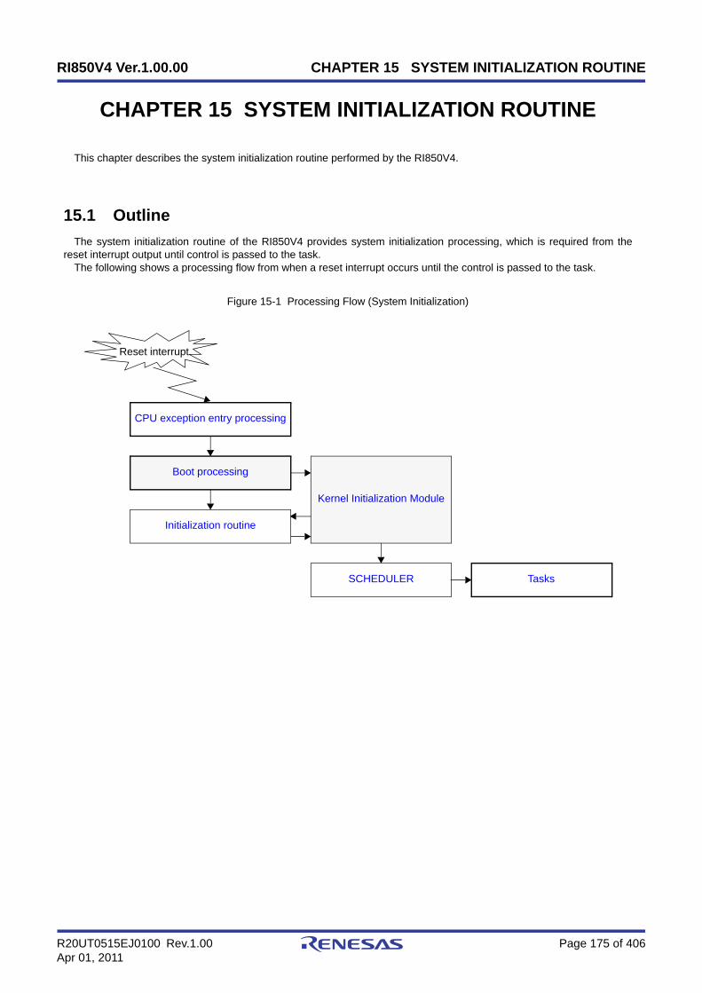
RI850V4 Ver.1.00.00 CHAPTER 15 SYSTEM INITIALIZATION ROUTINE
R20UT0515EJ0100 Rev.1.00 Page 175 of 406Apr 01, 2011
CHAPTER 15 SYSTEM INITIALIZATION ROUTINE
This chapter describes the system initialization routine performed by the RI850V4.
15.1 Outline
The system initialization routine of the RI850V4 provides system initialization processing, which is required from thereset interrupt output until control is passed to the task.
The following shows a processing flow from when a reset interrupt occurs until the control is passed to the task.
Figure 15-1 Processing Flow (System Initialization)
Reset interrupt
Boot processing
Kernel Initialization Module
Initialization routine
SCHEDULER Tasks
CPU exception entry processing

RI850V4 Ver.1.00.00 CHAPTER 15 SYSTEM INITIALIZATION ROUTINE
R20UT0515EJ0100 Rev.1.00 Page 176 of 406Apr 01, 2011
15.2 User-Own Coding Module
To support various execution environments, the RI850V4 extracts from the system initialization processing thehardware-dependent processing (Boot processing) that is required to execute processing, as a user-own coding module.This enhances portability for various execution environments and facilitates customization as well.
15.2.1 Boot processing
This is a routine dedicated to initialization processing that is extracted as a user-own coding module to initialize theminimum required hardware for the RI850V4 to perform processing, and is called from CPU exception entry processing.
- Basic form of boot processingCode boot processing by using the void type function that has no arguments.The following shows the basic form of boot processing in assembly.
[CA850/CX version]
[CCV850/CCV850E version]
- Internal processing of boot processingBoot processing is a routine dedicated to initialization processing that is called from CPU exception entry processing,without RI850V4 intervention.Therefore, note the following points when coding boot processing.
- Coding methodCode boot processing using C or assembly language.When coding in C, they can be coded in the same manner as ordinary functions coded.When coding in assembly language, code them according to the calling rules prescribed in the compiler used.
- Stack switchingSetting of stack pointer SP is not executed at the point when control is passed to boot processing.To use a boot processing dedicated stack, setting of stack pointer SP must therefore be coded at the beginning ofthe boot processing.
#include <kernel.h> /*Standard header file definition*/
.text .align 0x4 .globl __boot__boot : .extern __kernel_sit
/* ......... */
mov #__kernel_sit, r6 /*SIT start address setting*/ jarl __kernel_start, lp /*Jump to Kernel Initialization Module*/
#include <kernel.h> /*Standard header file definition*/
.text .align 0x4 .globl __boot__boot : .extern __kernel_sit
/* ......... */
mov __kernel_sit, r6 /*SIT start address setting*/ jarl __kernel_start, lp /*Jump to Kernel Initialization Module*/

RI850V4 Ver.1.00.00 CHAPTER 15 SYSTEM INITIALIZATION ROUTINE
R20UT0515EJ0100 Rev.1.00 Page 177 of 406Apr 01, 2011
- Service call issuanceExecution of the Kernel Initialization Module is not performed when boot processing is started. Issuance ofservice calls is therefore prohibited during boot processing.
The following lists processing that should be executed in boot processing.
- Setting of global pointer GP and text pointer TP
- Setting of element pointer EP
- Setting stack pointer SP
- Initialization of internal units and peripheral controllers
- Initialization of memory area without initial value
- Setting the start address of the system information table (SIT) to r6
- Passing of control to Kernel Initialization Module
Note 1 Global pointer gp, text pointer tp and element pointer ep must be set at the beginning of boot processing.Setting of stack pointer sp is required only when it uses the boot processing stack during boot processing.
Note 2 When using a CA850/CX version, set the data section base address to element pointer ep.When using a Single TDA model with a CCV850/CCV850E version, set the TDA base address to elementpointer ep.

RI850V4 Ver.1.00.00 CHAPTER 15 SYSTEM INITIALIZATION ROUTINE
R20UT0515EJ0100 Rev.1.00 Page 178 of 406Apr 01, 2011
15.3 Kernel Initialization Module
The kernel initialization module is a dedicated initialization processing routine provided for initializing the minimumrequired software for the RI850V4 to perform processing, and is called from Boot processing.
The following processing is executed in the kernel initialization module.
- Securement and initialization of management areas
- Management objectsSystem information tableSystem base tableReady queueInterrupt mask information tableInterrupt mask control tableKernel initialization routine information tableKernel common routine information blockversion information blocktask information blockTask control blockTask exception handling routine control blockSemaphore information blockSemaphore control blockEventflag information blockEventflag control blockData queue information blockData queue control blockMailbox information blockMailbox control blockMutex information blockMutex control blockFixed-sized memory pool information blockFixed-sized memory pool control blockVariable-sized memory pool information blockVariable-sized memory pool control blockCyclic handler information blockCyclic handler control blockExztended service call routine information blockInterrupt handler information blockInterrupt handler ID tableInitialization routine information blockIdle routine information block
- StackSystem stackTask stack
- BufferData queue
- Memory poolFixed-sized memory poolVariable-sized memory pool
- Initializing system time
- Registering timer handler
- Registering initialization routine
- Registering idle routine
- Calling of initialization routine

RI850V4 Ver.1.00.00 CHAPTER 15 SYSTEM INITIALIZATION ROUTINE
R20UT0515EJ0100 Rev.1.00 Page 179 of 406Apr 01, 2011
- Passing of control to scheduler
Note The kernel initialization module is included in system initialization processing provided by the RI850V4. Theuser is therefore not required to code the kernel initialization module.If the kernel initialization module is terminated abnormally, the values shown below will be set to register LP.
Macro Value Meaning
E_CFG_VER 1 version number is invalid.
E_CFG_CPU 2 processor type is invalid.
E_CFG_CC 3 The C compiler package type is invalid.
E_CFG_REG 4 register mode is invalid.
E_CFG_NOMEM 5 Insufficient memory

RI850V4 Ver.1.00.00 CHAPTER 16 DATA MACROS
R20UT0515EJ0100 Rev.1.00 Page 180 of 406Apr 01, 2011
CHAPTER 16 DATA MACROS
This chapter describes the data types, data structures and macros, which are used when issuing service calls providedby the RI850V4.
The definition of the macro and data structures is performed by each header file stored in <ri_root>\inc850.
Note <ri_root> indicates the installaion folder of RI850V4.The default folder is “C:\Program Files\Renesas Electronics\CubeSuite+\RI850V4.
16.1 Data Types
The Following lists the data types of parameters specified when issuing a service call.Macro definition of the data type is performed by header file <ri_root>\inc850\RI850V4\types.h, which is called from
ITRON general definitions header file <ri_root>\inc850\itron.h.
Table 16-1 Data Types
Macro Data Type Description
B signed char Signed 8-bit integer
H signed short Signed 16-bit integer
W signed long Signed 32-bit integer
UB unsigned char Unsigned 8-bit integer
UH unsigned short Unsigned 16-bit integer
UW unsigned long Unsigned 32-bit integer
VB signed char 8-bit value with unknown data type
VH signed short 16-bit value with unknown data type
VW signed long 32-bit value with unknown data type
VP void * Pointer to unknown data type
FP void (*) Processing unit start address (pointer to a function)
INT signed int Signed 32-bit integer
UINT unsigned int Unsigned 32-bit integer
BOOL signed long Boolean value (TRUE or FALSE)
FN signed short Function code
ER signed long Error code
ID signed short Object ID number
ATR unsigned short Object attribute
STAT unsigned short Object state
MODE unsigned short Service call operational mode
PRI signed short Priority
SIZE unsigned long Memory area size (in bytes)
TMO signed long Timeout (in millisecond)
RELTIM unsigned long Relative time (in millisecond)
VP_INT signed int Pointer to unknown data type, or signed 32-bit integer

RI850V4 Ver.1.00.00 CHAPTER 16 DATA MACROS
R20UT0515EJ0100 Rev.1.00 Page 181 of 406Apr 01, 2011
ER_BOOL signed long Error code, or boolean value (TRUE or FALSE)
ER_ID signed long Error code, or object ID number
ER_UINT signed int Error code, or signed 32-bit integer
TEXPTN unsigned int Task exception code, or pending exception code
FLGPTN unsigned int Bit pattern
INTNO unsigned short Exception code
EXCNO unsigned short Exception code
Macro Data Type Description

RI850V4 Ver.1.00.00 CHAPTER 16 DATA MACROS
R20UT0515EJ0100 Rev.1.00 Page 182 of 406Apr 01, 2011
16.2 Packet Formats
This section explains the data structures (task state packet, semaphore state packet, or the like) used when issuing aservice call provided by the RI850V4.
16.2.1 Task state packet
The following shows task state packet T_RTSK used when issuing ref_tsk or iref_tsk.Definition of task state packet T_RTSK is performed by header file <ri_root>\inc850\RI850V4\packet.h, which is called
from standard header file <ri_root>\inc850\kernel.h.
The following shows details on task state packet T_RTSK.
- tskstatStores the current state.
TTS_RUN: RUNNING stateTTS_RDY: READY stateTTS_WAI: WAITING stateTTS_SUS: SUSPENDED stateTTS_WAS: WAITING-SUSPENDED stateTTS_DMT: DORMANT state
- tskpriStores the current priority.
- tskbpriSystem-reserved area.
- tskwaitStores the reason for waiting.
TTW_SLP: Sleeping stateTTW_DLY: Delayed stateTTW_SEM: WAITING state for a semaphore resourceTTW_FLG: WAITING state for an eventflagTTW_SDTQ: Sending WAITING state for a data queueTTW_RDTQ: Receiving WAITING state for a data queueTTW_MBX: Receiving WAITING state for a mailboxTTW_MTX: WAITING state for a mutexTTW_MPF: WAITING state for a fixed-sized memory blockTTW_MPL: WAITING state for a variable-sized memory block
- wobjidStores the object ID number for which the task waiting.
typedef struct t_rtsk { STAT tskstat; /*Current state*/ PRI tskpri; /*Current priority*/ PRI tskbpri; /*Reserved for future use*/ STAT tskwait; /*Reason for waiting*/ ID wobjid; /*Object ID number for which the task waiting*/ TMO lefttmo; /*Remaining time until timeout*/ UINT actcnt; /*Activation request count*/ UINT wupcnt; /*Wakeup request count*/ UINT suscnt; /*Suspension count*/ ATR tskatr; /*Attribute*/ PRI itskpri; /*Initial priority*/ ID memid; /*Reserved for future use*/} T_RTSK;

RI850V4 Ver.1.00.00 CHAPTER 16 DATA MACROS
R20UT0515EJ0100 Rev.1.00 Page 183 of 406Apr 01, 2011
- lefttmoStores the remaining time until timeout (in millisecond).
- actcntStores the activation request count.
- wupcntStores the wakeup request count.
- suscntStores the suspension count.
- tskatrStores the attribute (coding languag, initial activation state, etc.).
Coding languag (bit 0)TA_HLNG: Start a task through a C language interface.TA_ASM: Start a task through an assembly language interface.
Initial activation state (bit 1)TA_ACT: Task is activated after the creation.
Initial preemption state (bit 14)TA_DISPREEMPT: Preemption is disabled at task activation.
Initial interrupt state (bit 15)TA_ENAINT: All interrupts are enabled at task activation.TA_DISINT: All interrupts are disabled at task activation.
[Structure of tskatr]
- itskpriStores the initial priority.
- memidSystem-reserved area.
011415
TA_DISPREEMPT
TA_ACTTA_ENAINTTA_DISINT : 1
TA_HLNG : 0TA_ASM : 1
: 1
: 1
: 0

RI850V4 Ver.1.00.00 CHAPTER 16 DATA MACROS
R20UT0515EJ0100 Rev.1.00 Page 184 of 406Apr 01, 2011
16.2.2 Task state packet (simplified version)
The following shows task state packet (simplified version) T_RTST used when issuing ref_tst or iref_tst.Definition of task state packet (simplified version) T_RTST is performed by header file
<ri_root>\inc850\RI850V4\packet.h, which is called from standard header file <ri_root>\inc850\kernel.h.
The following shows details on task state packet (simplified version) T_RTST.
- tskstatStores the current state.
TTS_RUN: RUNNING stateTTS_RDY: READY stateTTS_WAI: WAITING stateTTS_SUS: SUSPENDED stateTTS_WAS: WAITING-SUSPENDED stateTTS_DMT: DORMANT state
- tskwaitStores the reason for waiting.
TTW_SLP: Sleeping stateTTW_DLY: Delayed stateTTW_SEM: WAITING state for a semaphore resourceTTW_FLG: WAITING state for an eventflagTTW_SDTQ: Sending WAITING state for a data queueTTW_RDTQ: Receiving WAITING state for a data queueTTW_MBX: Receiving WAITING state for a mailboxTTW_MTX: WAITING state for a mutexTTW_MPF: WAITING state for a fixed-sized memory blockTTW_MPL: WAITING state for a variable-sized memory block
typedef struct t_rtst { STAT tskstat; /*Current state*/ STAT tskwait; /*Reason for waiting*/} T_RTST;

RI850V4 Ver.1.00.00 CHAPTER 16 DATA MACROS
R20UT0515EJ0100 Rev.1.00 Page 185 of 406Apr 01, 2011
16.2.3 Task exception handling routine state packet
The following shows task exception handling routine state packet T_RTEX used when issuing ref_tex or iref_tex.Definition of task exception handling routine state packet T_RTEX is performed by header file
<ri_root>\inc850\RI850V4\packet.h, which is called from standard header file <ri_root>\inc850\kernel.h.
The following shows details on task exception handling routine state packet T_RTEX.
- texstatStores the current state.
TTEX_ENA: Task exception enable stateTTEX_DIS: Task exception disable state
- pndptnStores the pending exception code.The pending exception code means the result of pending processing (OR of task exception codes) performed ifmultiple task exception handling requests are issued from when an exception handling request is issued by ras_tex oriras_tex until the target task moves to the RUNNING state.
Note 0x0 is stored if no exception handling request has been issued by ras_tex or iras_tex.
- texatrStores the attribute (coding languag).
Coding languag (bit 0)TA_HLNG: Start a task exception handling routine through a C language interface.TA_ASM: Start a task exception handling routine through an assembly language interface.
[Structure of texatr]
typedef struct t_rtex { STAT texstat; /*Current state*/ TEXPTN pndptn; /*Pending exception code*/ ATR texatr; /*Attribute*/} T_RTEX;
015
TA_HLNG : 0TA_ASM : 1

RI850V4 Ver.1.00.00 CHAPTER 16 DATA MACROS
R20UT0515EJ0100 Rev.1.00 Page 186 of 406Apr 01, 2011
16.2.4 Semaphore state packet
The following shows semaphore state packet T_RSEM used when issuing ref_sem or iref_sem.Definition of semaphore state packet T_RSEM is performed by header file <ri_root>\inc850\RI850V4\packet.h, which is
called from standard header file <ri_root>\inc850\kernel.h.
The following shows details on semaphore state packet T_RSEM.
- wtskidStores whether a task is queued to the semaphore wait queue.
TSK_NONE: No applicable taskValue: ID number of the task at the head of the wait queue
- semcntStores the current resource count.
- sematrStores the attribute (queuing method).
Task queuing method (bit 0)TA_TFIFO: Task wait queue is in FIFO order.TA_TPRI: Task wait queue is in task priority order.
[Structure of sematr]
- maxsemStores the maximum resource count.
typedef struct t_rsem { ID wtskid; /*Existence of waiting task*/ UINT semcnt; /*Current resource count*/ ATR sematr; /*Attribute*/ UINT maxsem; /*Maximum resource count*/} T_RSEM;
015
TA_TFIFO : 0TA_TPRI : 1

RI850V4 Ver.1.00.00 CHAPTER 16 DATA MACROS
R20UT0515EJ0100 Rev.1.00 Page 187 of 406Apr 01, 2011
16.2.5 Eventflag state packet
The following shows eventflag state packet T_RFLG used when issuing ref_flg or iref_flg.Definition of eventflag state packet T_RFLG is performed by header file <ri_root>\inc850\RI850V4\packet.h, which is
called from standard header file <ri_root>\inc850\kernel.h.
The following shows details on eventflag state packet T_RFLG.
- wtskidStores whether a task is queued to the event flag wait queue.
TSK_NONE: No applicable taskValue: ID number of the task at the head of the wait queue
- flgptnStores the Current bit pattern.
- flgatrStores the attribute (queuing method, queuing count, etc.).
Task queuing method (bit 0)TA_TFIFO: Task wait queue is in FIFO order.TA_TPRI: Task wait queue is in task priority order.
Queuing count (bit 1)TA_WSGL: Only one task is allowed to be in the WAITING state for the eventflag.TA_WMUL: Multiple tasks are allowed to be in the WAITING state for the eventflag.
Bit pattern clear (bit 2)TA_CLR: Bit pattern is cleared when a task is released from the WAITING state for eventflag.
[Structure of flgatr]
typedef struct t_rflg { ID wtskid; /*Existence of waiting task*/ FLGPTN flgptn; /*Current bit pattern*/ ATR flgatr; /*Attribute*/} T_RFLG;
015
TA_TFIFO : 0TA_TPRI : 1
TA_WSGL : 0TA_WMUL : 1
TA_CLR : 1
12

RI850V4 Ver.1.00.00 CHAPTER 16 DATA MACROS
R20UT0515EJ0100 Rev.1.00 Page 188 of 406Apr 01, 2011
16.2.6 Data queue state packet
The following shows data queue state packet T_RDTQ used when issuing ref_dtq or iref_dtq.Definition of data queue state packet T_RDTQ is performed by header file <ri_root>\inc850\RI850V4\packet.h, which is
called from standard header file <ri_root>\inc850\kernel.h.
The following shows details on data queue state packet T_RDTQ.
- stskidStores whether a task is queued to the transmission wait queue of the data queue.
TSK_NONE: No applicable taskValue: ID number of the task at the head of the wait queue
- rtskidStores whether a task is queued to the reception wait queue of the data queue.
TSK_NONE: No applicable taskValue: ID number of the task at the head of the wait queue
- sdtqcntStores the number of data elements in data queue.
- dtqatrStores the attribute (queuing method).
Task queuing method (bit 0)TA_TFIFO: Task wait queue is in FIFO order.TA_TPRI: Task wait queue is in task priority order.
[Structure of dtqatr]
- dtqcntStores the data count.
- memidSystem-reserved area.
typedef struct t_rdtq { ID stskid; /*Existence of tasks waiting for data transmission*/ ID rtskid; /*Existence of tasks waiting for data reception*/ UINT sdtqcnt; /*number of data elements in the data queue*/ ATR dtqatr; /*Attribute*/ UINT dtqcnt; /*Data count*/ ID memid; /*Reserved for future use*/} T_RDTQ;
015
TA_TFIFO : 0TA_TPRI : 1

RI850V4 Ver.1.00.00 CHAPTER 16 DATA MACROS
R20UT0515EJ0100 Rev.1.00 Page 189 of 406Apr 01, 2011
16.2.7 Message packet
The following shows message packet T_MSG/T_MSG_PRI used when issuing snd_mbx, isnd_mbx, rcv_mbx,prcv_mbx, iprcv_mbx or trcv_mbx.
Definition of message packet T_MSG/T_MSG_PRI is performed by header file <ri_root>\inc850\RI850V4\packet.h,which is called from standard header file <ri_root>\inc850\kernel.h.
[Message packet for TA_MFIFO attribute ]
[Message packet for TA_MPRI attribute]
The following shows details on message packet T_RTSK/T_MSG_PRI.
- msgnext, msgqueSystem-reserved area.
- msgpriStores the message priority.
Note 1 In the RI850V4, a message having a smaller priority number is given a higher priority.
Note 2 Values that can be specified as the message priority level are limited to the range defined in Mailboxinformation (Maximum message priority: maxmpri) when the system configuration file is created.
typedef struct t_msg { struct t_msg *msgnext; /*Reserved for future use*/} T_MSG;
typedef struct t_msg_pri { struct t_msg msgque; /*Reserved for future use*/ PRI msgpri; /*Message priority*/} T_MSG_PRI;
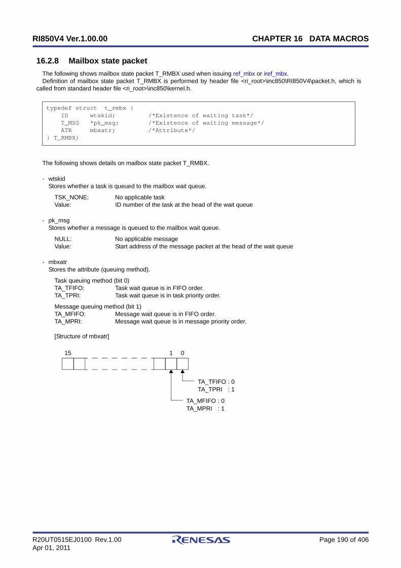
RI850V4 Ver.1.00.00 CHAPTER 16 DATA MACROS
R20UT0515EJ0100 Rev.1.00 Page 190 of 406Apr 01, 2011
16.2.8 Mailbox state packet
The following shows mailbox state packet T_RMBX used when issuing ref_mbx or iref_mbx.Definition of mailbox state packet T_RMBX is performed by header file <ri_root>\inc850\RI850V4\packet.h, which is
called from standard header file <ri_root>\inc850\kernel.h.
The following shows details on mailbox state packet T_RMBX.
- wtskidStores whether a task is queued to the mailbox wait queue.
TSK_NONE: No applicable taskValue: ID number of the task at the head of the wait queue
- pk_msgStores whether a message is queued to the mailbox wait queue.
NULL: No applicable messageValue: Start address of the message packet at the head of the wait queue
- mbxatrStores the attribute (queuing method).
Task queuing method (bit 0)TA_TFIFO: Task wait queue is in FIFO order.TA_TPRI: Task wait queue is in task priority order.
Message queuing method (bit 1)TA_MFIFO: Message wait queue is in FIFO order.TA_MPRI: Message wait queue is in message priority order.
[Structure of mbxatr]
typedef struct t_rmbx { ID wtskid; /*Existence of waiting task*/ T_MSG *pk_msg; /*Existence of waiting message*/ ATR mbxatr; /*Attribute*/} T_RMBX;
TA_TFIFO
0115
TA_TPRI
TA_MFIFOTA_MPRI
: 0: 1
: 0: 1

RI850V4 Ver.1.00.00 CHAPTER 16 DATA MACROS
R20UT0515EJ0100 Rev.1.00 Page 191 of 406Apr 01, 2011
16.2.9 Mutex state packet
The following shows mutex state packet T_RMTX used when issuing ref_mtx or iref_mtx.Definition of mutex state packet T_RMTX is performed by header file <ri_root>\inc850\RI850V4\packet.h, which is
called from standard header file <ri_root>\inc850\kernel.h.
The following shows details on mutex state packet T_RMTX.
- htskidStores whether a task that is locking a mutex exists.
TSK_NONE: No applicable taskValue: ID number of the task locking the mutex
- wtskidStores whether a task is queued to the mutex wait queue.
TSK_NONE: No applicable taskValue: ID number of the task at the head of the wait queue
- mtxatrStores the attribute (queuing method).
Task queuing method (bit 0 to 1)TA_TFIFO: Task wait queue is in FIFO order.TA_TPRI: Task wait queue is in task priority order.
[Structure of mtxatr]
- ceilpriSystem-reserved area.
typedef struct t_rmtx { ID htskid; /*Existence of locked mutex*/ ID wtskid; /*Existence of waiting task*/ ATR mtxatr; /*Attribute*/ PRI ceilpri; /*Reserved for future use*/} T_RMTX;
015
TA_TFIFO : 0TA_TPRI : 1

RI850V4 Ver.1.00.00 CHAPTER 16 DATA MACROS
R20UT0515EJ0100 Rev.1.00 Page 192 of 406Apr 01, 2011
16.2.10 Fixed-sized memory pool state packet
The following shows fixed-sized memory pool state packet T_RMPF used when issuing ref_mpf or iref_mpf.Definition of fixed-sized memory pool state packet T_RMPF is performed by header file
<ri_root>\inc850\RI850V4\packet.h, which is called from standard header file <ri_root>\inc850\kernel.h.
The following shows details on fixed-sized memory pool state packet T_RMPF.
- wtskidStores whether a task is queued to the fixed-size memory pool.
TSK_NONE: No applicable taskValue: ID number of the task at the head of the wait queue
- fblkcntStores the number of free memory blocks.
- mpfatrStores the attribute (queuing method).
Task queuing method (bit 0)TA_TFIFO: Task wait queue is in FIFO order.TA_TPRI: Task wait queue is in task priority order.
[Structure of mpfatr]
- memidSystem-reserved area.
typedef struct t_rmpf { ID wtskid; /*Existence of waiting task*/ UINT fblkcnt; /*Number of free memory blocks*/ ATR mpfatr; /*Attribute*/ ID memid; /*Reserved for future use*/} T_RMPF;
015
TA_TFIFO : 0TA_TPRI : 1

RI850V4 Ver.1.00.00 CHAPTER 16 DATA MACROS
R20UT0515EJ0100 Rev.1.00 Page 193 of 406Apr 01, 2011
16.2.11 Variable-sized memory pool state packet
The following shows variable-sized memory pool state packet T_RMPL used when issuing ref_mpl or iref_mpl.Definition of variable-sized memory pool state packet T_RMPL is performed by header file
<ri_root>\inc850\RI850V4\packet.h, which is called from standard header file <ri_root>\inc850\kernel.h.
The following shows details on variable-sized memory pool state packet T_RMPL.
- wtskidStores whether a task is queued to the variable-size memory pool wait queue.
TSK_NONE: No applicable taskValue: ID number of the task at the head of the wait queue
- fmplszStores the total size of free memory blocks (in bytes).
- fblkszStores the maximum memory block size available (in bytes).
- mplatrStores the attribute (queuing method).
Task queuing method (bit 0)TA_TFIFO: Task wait queue is in FIFO order.TA_TPRI: Task wait queue is in task priority order.
[Structure of mplatr]
- memidSystem-reserved area.
typedef struct t_rmpl { ID wtskid; /*Existence of waiting task*/ SIZE fmplsz; /*Total size of free memory blocks*/ UINT fblksz; /*Maximum memory block size available*/ ATR mplatr; /*Attribute*/ ID memid; /*Reserved for future use*/} T_RMPL;
015
TA_TFIFO : 0TA_TPRI : 1

RI850V4 Ver.1.00.00 CHAPTER 16 DATA MACROS
R20UT0515EJ0100 Rev.1.00 Page 194 of 406Apr 01, 2011
16.2.12 System time packet
The following shows system time packet SYSTIM used when issuing set_tim, iset_tim, get_tim or iget_tim.Definition of system time packet SYSTIM is performed by header file <ri_root>\inc850\RI850V4\packet.h, which is called
from standard header file <ri_root>\inc850\kernel.h.
The following shows details on system time packet SYSTIM.
- ltimeStores the system time (lower 32 bits).
- utimeStores the system time (higher 16 bits).
typedef struct t_systim { UW ltime; /*System time (lower 32 bits)*/ UH utime; /*System time (higher 16 bits)*/} SYSTIM;

RI850V4 Ver.1.00.00 CHAPTER 16 DATA MACROS
R20UT0515EJ0100 Rev.1.00 Page 195 of 406Apr 01, 2011
16.2.13 Cyclic handler state packet
The following shows cyclic handler state packet T_RCYC used when issuing ref_cyc or iref_cyc.Definition of cyclic handler state packet T_RCYC is performed by header file <ri_root>\inc850\RI850V4\packet.h, which
is called from standard header file <ri_root>\inc850\kernel.h.
The following shows details on cyclic handler state packet T_RCYC.
- cycstatStore the current state.
TCYC_STP: Non-operational stateTCYC_STA: Operational state
- lefttimStores the time left before the next activation (in millisecond).
- cycatrStores the attribute (coding languag, initial activation state, etc.).
Coding languag (bit 0)TA_HLNG: Start a cyclic handler through a C language interface.TA_ASM: Start a cyclic handler through an assembly language interface.
Initial activation state (bit 1)TA_STA: Cyclic handlers is in an operational state after the creation.
Existence of saved activation phases (bit 2)TA_PHS: Cyclic handler is activated preserving the activation phase.
[Structure of cycatr]
- cyctimStores the activation cycle (in millisecond).
- cycphsStores the activation phase (in millisecond).In the RI850V4, the initial activation phase means the relative interval from when generation of s cyclic handler iscompleted until the first activation request is issued.
typedef struct t_rcyc { STAT cycstat; /*Current state*/ RELTIM lefttim; /*Time left before the next activation*/ ATR cycatr; /*Attribute*/ RELTIM cyctim; /*Activation cycle*/ RELTIM cycphs; /*Activation phase*/} T_RCYC;
015 1
TA_STA
TA_PHS
: 1
: 1
2
TA_HLNG : 0TA_ASM : 1

RI850V4 Ver.1.00.00 CHAPTER 16 DATA MACROS
R20UT0515EJ0100 Rev.1.00 Page 196 of 406Apr 01, 2011
16.3 Data Macros
This section explains the data macros (for current state, processing program attributes, or the like) used when issuing aservice call provided by the RI850V4.
16.3.1 Current state
The following lists the management object current states acquired by issuing service calls (ref_tsk, ref_sem, or the like).Macro definition of the current state is performed by header file <ri_root>\inc850\RI850V4\option.h, which is called from
ITRON general definitions header file <ri_root>\inc850\itron.h.
Table 16-2 Current State
Macro Value Description
TTS_RUN 0x01 RUNNING state
TTS_RDY 0x02 READY state
TTS_WAI 0x04 WAITING state
TTS_SUS 0x08 SUSPENDED state
TTS_WAS 0x0c WAITING-SUSPENDED state
TTS_DMT 0x10 DORMANT state
TTEX_ENA 0x00 Task exception enable state
TTEX_DIS 0x01 Task exception disable state
TCYC_STP 0x00 Non-operational state
TCYC_STA 0x01 Operational state
TTW_SLP 0x0001 Sleeping state
TTW_DLY 0x0002 Delayed state
TTW_SEM 0x0004 WAITING state for a semaphore resource
TTW_FLG 0x0008 WAITING state for an eventflag
TTW_SDTQ 0x0010 Sending WAITING state for a data queue
TTW_RDTQ 0x0020 Receiving WAITING state for a data queue
TTW_MBX 0x0040 Receiving WAITING state for a mailbox
TTW_MTX 0x0080 WAITING state for a mutex
TTW_MPF 0x2000 WAITING state for a fixed-sized memory pool
TTW_MPL 0x4000 WAITING state for a variable-sized memory pool
TSK_NONE 0 No applicable task

RI850V4 Ver.1.00.00 CHAPTER 16 DATA MACROS
R20UT0515EJ0100 Rev.1.00 Page 197 of 406Apr 01, 2011
16.3.2 Processing program attributes
The following lists the processing program attributes acquired by issuing service calls (ref_tsk, ref_cyc, or the like).Macro definition of attributes is performed by header file<ri_root>\inc850\RI850V4\option.h, which is called from ITRON
general definitions header file <ri_root>\inc850\itron.h.
Table 16-3 Processing Program Attributes
16.3.3 Management object attributes
The following lists the management object attributes acquired by issuing service calls (ref_sem, ref_flg, or the like).Macro definition of attributes is performed by header file<ri_root>\inc850\RI850V4\option.h, which is called from ITRON
general definitions header file <ri_root>\inc850\itron.h.
Table 16-4 Management Object Attributes
Macro Value Description
TA_HLNG 0x0000 Start a processing unit through a C language interface.
TA_ASM 0x0001 Start a processing unit through an assembly languageinterface.
TA_ACT 0x0002 Task is activated after the creation.
TA_DISPREEMPT 0x4000 Preemption is disabled at task activation.
TA_ENAINT 0x0000 All interrupts are enabled at task activation.
TA_DISINT 0x8000 All interrupts are disabled at task activation.
TA_STA 0x0002 Cyclic handlers is in an operational state after the cre-ation.
TA_PHS 0x0004 Cyclic handler is activated preserving the activationphase.
Macro Value Description
TA_TFIFO 0x0000 Task wait queue is in FIFO order.
TA_TPRI 0x0001 Task wait queue is in task priority order.
TA_WSGL 0x0000 Only one task is allowed to be in the WAITING state forthe eventflag.
TA_WMUL 0x0002 Multiple tasks are allowed to be in the WAITING state forthe eventflag.
TA_CLR 0x0004 Bit pattern is cleared when a task is released from theWAITING state for eventflag.
TA_MFIFO 0x0000 Message wait queue is in FIFO order.
TA_MPRI 0x0002 Message wait queue is in message priority order.
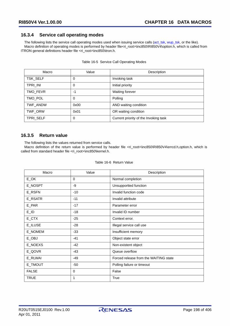
RI850V4 Ver.1.00.00 CHAPTER 16 DATA MACROS
R20UT0515EJ0100 Rev.1.00 Page 198 of 406Apr 01, 2011
16.3.4 Service call operating modes
The following lists the service call operating modes used when issuing service calls (act_tsk, wup_tsk, or the like).Macro definition of operating modes is performed by header file<ri_root>\inc850\RI850V4\option.h, which is called from
ITRON general definitions header file <ri_root>\inc850\itron.h.
Table 16-5 Service Call Operating Modes
16.3.5 Return value
The following lists the values returned from service calls.Macro definition of the return value is performed by header file <ri_root>\inc850\RI850V4\errcd.h,option.h, which is
called from standard header file <ri_root>\inc850\kernel.h.
Table 16-6 Return Value
Macro Value Description
TSK_SELF 0 Invoking task
TPRI_INI 0 Initial priority
TMO_FEVR -1 Waiting forever
TMO_POL 0 Polling
TWF_ANDW 0x00 AND waiting condition
TWF_ORW 0x01 OR waiting condition
TPRI_SELF 0 Current priority of the Invoking task
Macro Value Description
E_OK 0 Normal completion
E_NOSPT -9 Unsupportted function
E_RSFN -10 Invalid function code
E_RSATR -11 Invalid attribute
E_PAR -17 Parameter error
E_ID -18 Invalid ID number
E_CTX -25 Context error.
E_ILUSE -28 Illegal service call use
E_NOMEM -33 Insufficient memory
E_OBJ -41 Object state error
E_NOEXS -42 Non-existent object
E_QOVR -43 Queue overflow
E_RLWAI -49 Forced release from the WAITING state
E_TMOUT -50 Polling failure or timeout
FALSE 0 False
TRUE 1 True
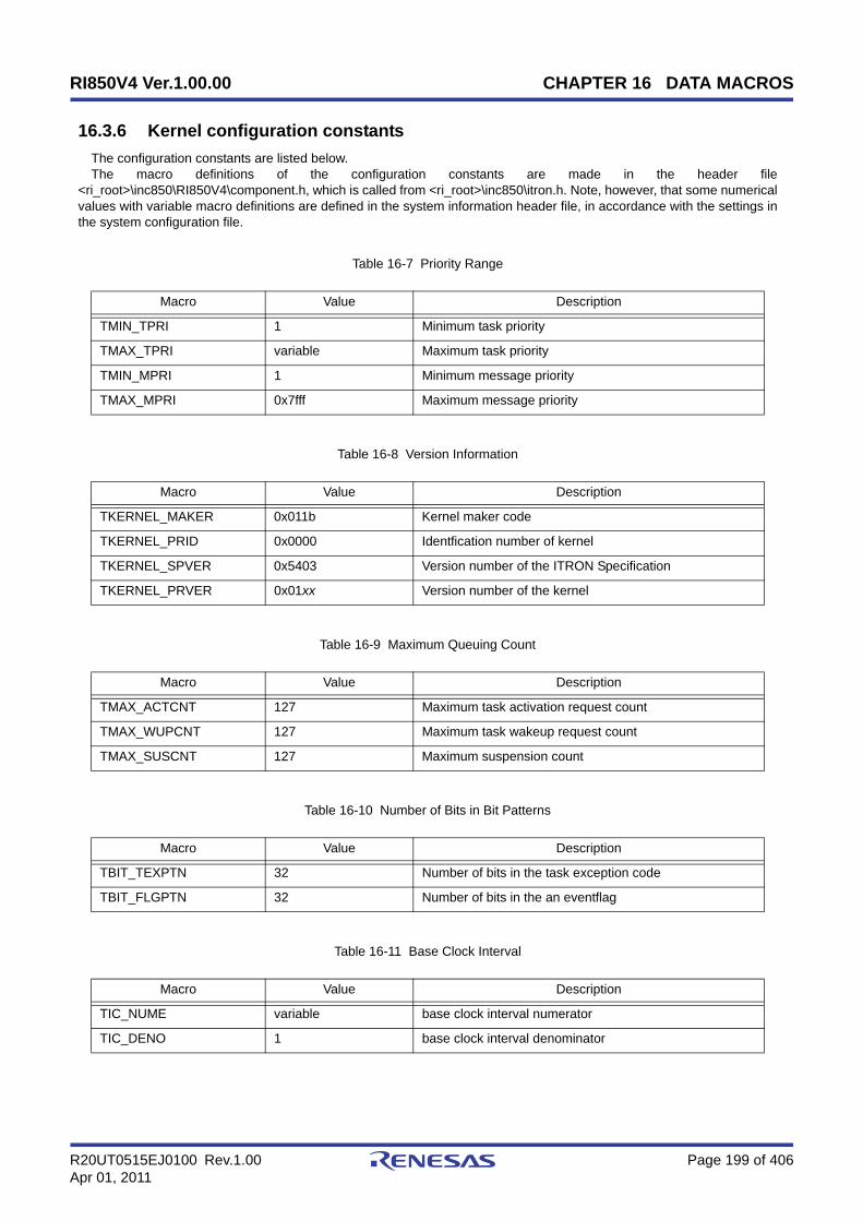
RI850V4 Ver.1.00.00 CHAPTER 16 DATA MACROS
R20UT0515EJ0100 Rev.1.00 Page 199 of 406Apr 01, 2011
16.3.6 Kernel configuration constants
The configuration constants are listed below.The macro definitions of the configuration constants are made in the header file
<ri_root>\inc850\RI850V4\component.h, which is called from <ri_root>\inc850\itron.h. Note, however, that some numericalvalues with variable macro definitions are defined in the system information header file, in accordance with the settings inthe system configuration file.
Table 16-7 Priority Range
Table 16-8 Version Information
Table 16-9 Maximum Queuing Count
Table 16-10 Number of Bits in Bit Patterns
Table 16-11 Base Clock Interval
Macro Value Description
TMIN_TPRI 1 Minimum task priority
TMAX_TPRI variable Maximum task priority
TMIN_MPRI 1 Minimum message priority
TMAX_MPRI 0x7fff Maximum message priority
Macro Value Description
TKERNEL_MAKER 0x011b Kernel maker code
TKERNEL_PRID 0x0000 Identfication number of kernel
TKERNEL_SPVER 0x5403 Version number of the ITRON Specification
TKERNEL_PRVER 0x01xx Version number of the kernel
Macro Value Description
TMAX_ACTCNT 127 Maximum task activation request count
TMAX_WUPCNT 127 Maximum task wakeup request count
TMAX_SUSCNT 127 Maximum suspension count
Macro Value Description
TBIT_TEXPTN 32 Number of bits in the task exception code
TBIT_FLGPTN 32 Number of bits in the an eventflag
Macro Value Description
TIC_NUME variable base clock interval numerator
TIC_DENO 1 base clock interval denominator

RI850V4 Ver.1.00.00 CHAPTER 16 DATA MACROS
R20UT0515EJ0100 Rev.1.00 Page 200 of 406Apr 01, 2011
16.4 Conditional Compile Macro
The header file of the RI850V4 is conditionally compiled by the following macros.Define macros (compiler's activation option -D, or the like) according to the use environment.
Table 16-12 Conditional Compile Macro
Classification Macro Description
C compiler package__rel__ The CA850/CX is used.
__ghs__ The CCV850/CCV850E is used.
CPU type__v850e__ V850E1/V850E2/V850ES core
__v850e2m__ V850E2M core
Register mode
__r22__ 22-register mode
__r26__ 26-register mode
__r32__ 32-regiter mode

RI850V4 Ver.1.00.00 CHAPTER 17 SERVICE CALLS
R20UT0515EJ0100 Rev.1.00 Page 201 of 406Apr 01, 2011
CHAPTER 17 SERVICE CALLS
This chapter describes the service calls supported by the RI850V4.
17.1 Outline
The service calls provided by the RI850V4 are service routines provided for indirectly manipulating the resources (tasks,semaphores, etc.) managed by the RI850V4 from a processing program.
The service calls provided by the RI850V4 are listed below by management module.
- Task management functions
act_tsk, iact_tsk, can_act, ican_act, sta_tsk, ista_tsk, ext_tsk, ter_tsk, chg_pri, ichg_pri, get_pri, iget_pri, ref_tsk,iref_tsk, ref_tst, iref_tst
- Task dependent synchronization functions
slp_tsk, tslp_tsk, wup_tsk, iwup_tsk, can_wup, ican_wup, rel_wai, irel_wai, sus_tsk, isus_tsk, rsm_tsk, irsm_tsk,frsm_tsk, ifrsm_tsk, dly_tsk
- Task exception handling functions
ras_tex, iras_tex, dis_tex, ena_tex, sns_tex, ref_tex, iref_tex
- Synchronization and communication functions (semaphores)
wai_sem, pol_sem, ipol_sem, twai_sem, sig_sem, isig_sem, ref_sem, iref_sem
- Synchronization and communication functions (eventflags)
set_flg, iset_flg, clr_flg, iclr_flg, wai_flg, pol_flg, ipol_flg, twai_flg, ref_flg, iref_flg
- Synchronization and communication functions (data queues)
snd_dtq, psnd_dtq, ipsnd_dtq, tsnd_dtq, fsnd_dtq, ifsnd_dtq, rcv_dtq, prcv_dtq, iprcv_dtq, trcv_dtq, ref_dtq, iref_dtq
- Synchronization and communication functions (mailboxes)
snd_mbx, isnd_mbx, rcv_mbx, prcv_mbx, iprcv_mbx, trcv_mbx, ref_mbx, iref_mbx
- Extended synchronization and communication functions (mutexes)
loc_mtx, ploc_mtx, tloc_mtx, unl_mtx, ref_mtx, iref_mtx
- Memory pool management functions (fixed-sized memory pools)
get_mpf, pget_mpf, ipget_mpf, tget_mpf, rel_mpf, irel_mpf, ref_mpf, iref_mpf
- Memory pool management functions (variable-sized memory pools)
get_mpl, pget_mpl, ipget_mpl, tget_mpl, rel_mpl, irel_mpl, ref_mpl, iref_mpl
- Time management functions
set_tim, iset_tim, get_tim, iget_tim, sta_cyc, ista_cyc, stp_cyc, istp_cyc, ref_cyc, iref_cyc
- System state management functions
rot_rdq, irot_rdq, vsta_sch, get_tid, iget_tid, loc_cpu, iloc_cpu, unl_cpu, iunl_cpu, sns_loc, dis_dsp, ena_dsp,sns_dsp, sns_ctx, sns_dpn
- Interrupt management functions
dis_int, ena_int, chg_ims, ichg_ims, get_ims, iget_ims

RI850V4 Ver.1.00.00 CHAPTER 17 SERVICE CALLS
R20UT0515EJ0100 Rev.1.00 Page 202 of 406Apr 01, 2011
- Service call management functions
cal_svc, ical_svc
17.1.1 Call service call
The method for calling service calls from processing programs coded either in C or assembly language is describedbelow.
- C languageBy calling using the same method as for normal C functions, service call parameters are handed over to the RI850V4as arguments and the relevant processing is executed.
- Assembly languageWhen issuing a service call from a processing program coded in assembly language, set parameters and the returnaddress according to the calling rules prescribed in the C compiler used as the development environment and call thefunction using the jarl instruction; the service call parameters are then transferred to the RI850V4 as arguments andthe relevant processing will be executed.
Note To call the service calls provided by the RI850V4 from a processing program, the header files listed below mustbe coded (include processing).
kernel.h: Standard header file
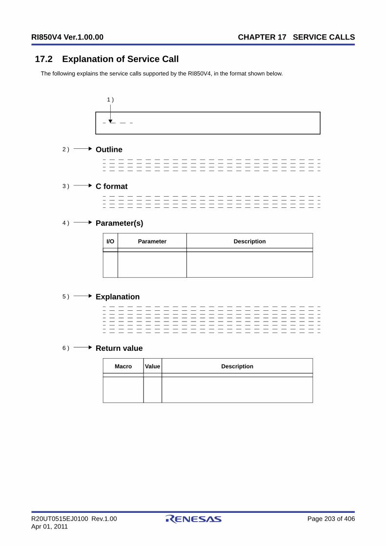
RI850V4 Ver.1.00.00 CHAPTER 17 SERVICE CALLS
R20UT0515EJ0100 Rev.1.00 Page 203 of 406Apr 01, 2011
17.2 Explanation of Service Call
The following explains the service calls supported by the RI850V4, in the format shown below.
Outline
DescriptionParameterI/O
C format
Explanation
1 )
2 )
3 )
4 )
5 )
6 ) Return value
Parameter(s)
DescriptionValueMacro

RI850V4 Ver.1.00.00 CHAPTER 17 SERVICE CALLS
R20UT0515EJ0100 Rev.1.00 Page 204 of 406Apr 01, 2011
1 ) NameIndicates the name of the service call.
2 ) OutlineOutlines the functions of the service call.
3 ) C formatIndicates the format to be used when describing a service call to be issued in C language.
4 ) Parameter(s)Service call parameters are explained in the following format.
A ) Parameter classification I: Parameter input to RI850V4.O: Parameter output from RI850V4.
B ) Parameter data type
C ) Description of parameter
5 ) ExplanationExplains the function of a service call.
6 ) Return valueIndicates a service call's return value using a macro and value.
A ) Macro of return value
B ) Value of return value
C ) Description of return value
I/O Parameter Description
A B C
Macro Value Description
A B C

RI850V4 Ver.1.00.00 CHAPTER 17 SERVICE CALLS
R20UT0515EJ0100 Rev.1.00 Page 205 of 406Apr 01, 2011
17.2.1 Task management functions
The following shows the service calls provided by the RI850V4 as the task management functions.
Table 17-1 Task Management Functions
Service Call Function Origin of Service Call
act_tsk Activate task (queues an activation request) Task, Non-task, Initialization rou-tine
iact_tsk Activate task (queues an activation request) Task, Non-task, Initialization rou-tine
can_act Cancel task activation requests Task, Non-task, Initialization rou-tine
ican_act Cancel task activation requests Task, Non-task, Initialization rou-tine
sta_tsk Activate task (does not queue an activation request) Task, Non-task, Initialization rou-tine
ista_tsk Activate task (does not queue an activation request) Task, Non-task, Initialization rou-tine
ext_tsk Terminate invoking task Task
ter_tsk Terminate task Task, Initialization routine
chg_pri Change task priority Task, Non-task, Initialization rou-tine
ichg_pri Change task priority Task, Non-task, Initialization rou-tine
get_pri Reference task priority Task, Non-task, Initialization rou-tine
iget_pri Reference task priority Task, Non-task, Initialization rou-tine
ref_tsk Reference task state Task, Non-task, Initialization rou-tine
iref_tsk Reference task state Task, Non-task, Initialization rou-tine
ref_tst Reference task state (simplified version) Task, Non-task, Initialization rou-tine
iref_tst Reference task state (simplified version) Task, Non-task, Initialization rou-tine
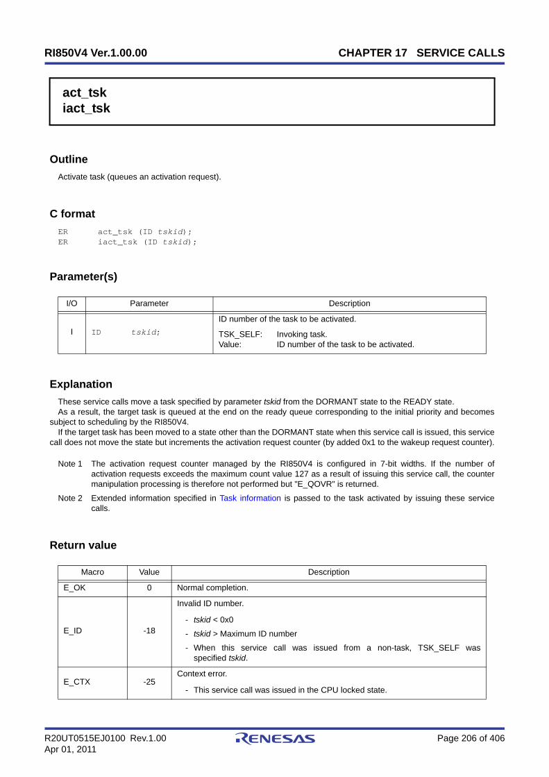
RI850V4 Ver.1.00.00 CHAPTER 17 SERVICE CALLS
R20UT0515EJ0100 Rev.1.00 Page 206 of 406Apr 01, 2011
act_tskiact_tsk
Outline
Activate task (queues an activation request).
C format
ER act_tsk (ID tskid);ER iact_tsk (ID tskid);
Parameter(s)
Explanation
These service calls move a task specified by parameter tskid from the DORMANT state to the READY state.As a result, the target task is queued at the end on the ready queue corresponding to the initial priority and becomes
subject to scheduling by the RI850V4.If the target task has been moved to a state other than the DORMANT state when this service call is issued, this service
call does not move the state but increments the activation request counter (by added 0x1 to the wakeup request counter).
Note 1 The activation request counter managed by the RI850V4 is configured in 7-bit widths. If the number ofactivation requests exceeds the maximum count value 127 as a result of issuing this service call, the countermanipulation processing is therefore not performed but "E_QOVR" is returned.
Note 2 Extended information specified in Task information is passed to the task activated by issuing these servicecalls.
Return value
I/O Parameter Description
I ID tskid;
ID number of the task to be activated.
TSK_SELF: Invoking task.Value: ID number of the task to be activated.
Macro Value Description
E_OK 0 Normal completion.
E_ID -18
Invalid ID number.
- tskid < 0x0
- tskid > Maximum ID number
- When this service call was issued from a non-task, TSK_SELF wasspecified tskid.
E_CTX -25Context error.
- This service call was issued in the CPU locked state.

RI850V4 Ver.1.00.00 CHAPTER 17 SERVICE CALLS
R20UT0515EJ0100 Rev.1.00 Page 207 of 406Apr 01, 2011
E_NOEXS -42Non-existent object.
- Specified task is not registered.
E_QOVR -43Queue overflow.
- Activation request count exceeded 127.
Macro Value Description
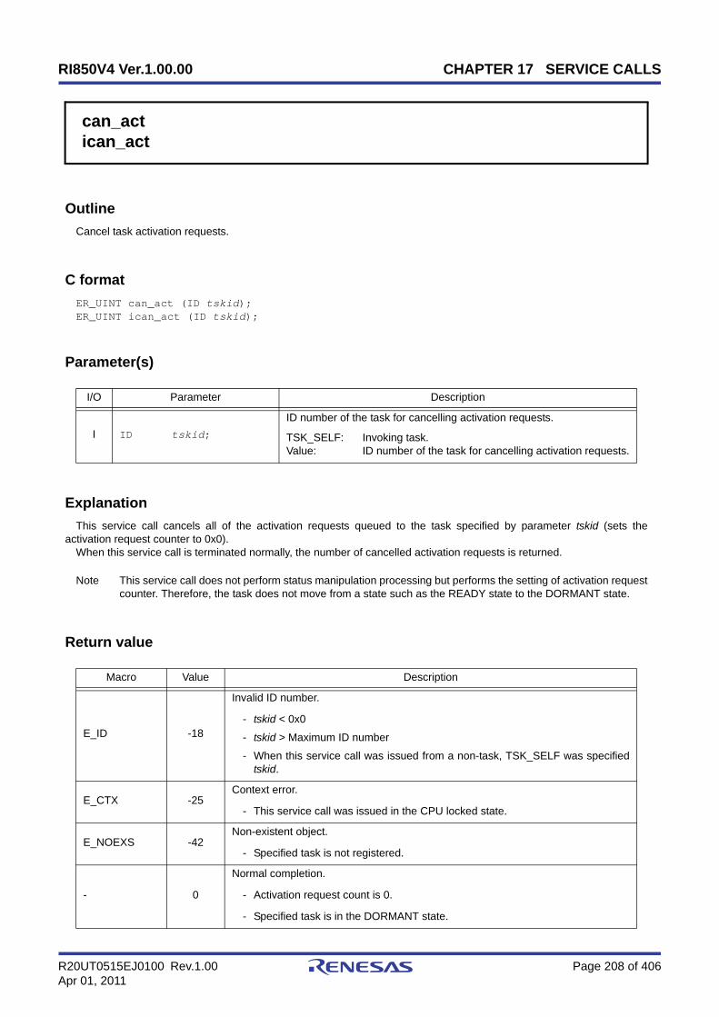
RI850V4 Ver.1.00.00 CHAPTER 17 SERVICE CALLS
R20UT0515EJ0100 Rev.1.00 Page 208 of 406Apr 01, 2011
can_actican_act
Outline
Cancel task activation requests.
C format
ER_UINT can_act (ID tskid);ER_UINT ican_act (ID tskid);
Parameter(s)
Explanation
This service call cancels all of the activation requests queued to the task specified by parameter tskid (sets theactivation request counter to 0x0).
When this service call is terminated normally, the number of cancelled activation requests is returned.
Note This service call does not perform status manipulation processing but performs the setting of activation requestcounter. Therefore, the task does not move from a state such as the READY state to the DORMANT state.
Return value
I/O Parameter Description
I ID tskid;
ID number of the task for cancelling activation requests.
TSK_SELF: Invoking task.Value: ID number of the task for cancelling activation requests.
Macro Value Description
E_ID -18
Invalid ID number.
- tskid < 0x0
- tskid > Maximum ID number
- When this service call was issued from a non-task, TSK_SELF was specifiedtskid.
E_CTX -25Context error.
- This service call was issued in the CPU locked state.
E_NOEXS -42Non-existent object.
- Specified task is not registered.
- 0
Normal completion.
- Activation request count is 0.
- Specified task is in the DORMANT state.

RI850V4 Ver.1.00.00 CHAPTER 17 SERVICE CALLS
R20UT0515EJ0100 Rev.1.00 Page 209 of 406Apr 01, 2011
Positive value - Normal completion (activation request count).
Macro Value Description

RI850V4 Ver.1.00.00 CHAPTER 17 SERVICE CALLS
R20UT0515EJ0100 Rev.1.00 Page 210 of 406Apr 01, 2011
sta_tskista_tsk
Outline
Activate task (does not queue an activation request).
C format
ER sta_tsk (ID tskid, VP_INT stacd);ER ista_tsk (ID tskid, VP_INT stacd);
Parameter(s)
Explanation
These service calls move a task specified by parameter tskid from the DORMANT state to the READY state.As a result, the target task is queued at the end on the ready queue corresponding to the initial priority and becomes
subject to scheduling by the RI850V4.This service call does not perform queuing of activation requests. If the target task is in a state other than the
DORMANT state, the status manipulation processing for the target task is therefore not performed but "E_OBJ" is returnedSpecify for parameter stacd the extended information transferred to the target task.
Return value
I/O Parameter Description
I ID tskid; ID number of the task to be activated.
I VP_INT stacd; Start code (extended information) of the task.
Macro Value Description
E_OK 0 Normal completion.
E_ID -18
Invalid ID number.
- tskid < 0x0
- tskid > Maximum ID number
E_CTX -25Context error.
- This service call was issued in the CPU locked state.
E_OBJ -41Object state error
- Specified task is not in the DORMANT state.
E_NOEXS -42Non-existent object.
- Specified task is not registered.

RI850V4 Ver.1.00.00 CHAPTER 17 SERVICE CALLS
R20UT0515EJ0100 Rev.1.00 Page 211 of 406Apr 01, 2011
ext_tsk
Outline
Terminate invoking task.
C format
void ext_tsk (void);
Parameter(s)
None.
Explanation
This service call moves an invoking task from the RUNNING state to the DORMANT state.As a result, the invoking task is unlinked from the ready queue and excluded from the RI850V4 scheduling subject.If an activation request has been queued to the invoking task (the activation request counter is not set to 0x0) when this
service call is issued, this service call moves the task from the RUNNING state to the DORMANT state, decrements thewakeup request counter (by subtracting 0x1 from the wakeup request counter), and then moves the task from theDORMANT state to the READY state.
Note 1 When moving a task from the RUNNING state to the DORMANT state, this service call initializes the followinginformation to values that are set during task creation.
- Current priority
- Wakeup request count
- Suspension count
- interrupt state
If an invoking task has locked a mutex, the locked state is released at the same time (processing equivalent tounl_mtx).
Note 2 When the return instruction is issued in a task, the same processing as ext_tsk is performed.
Return value
None.
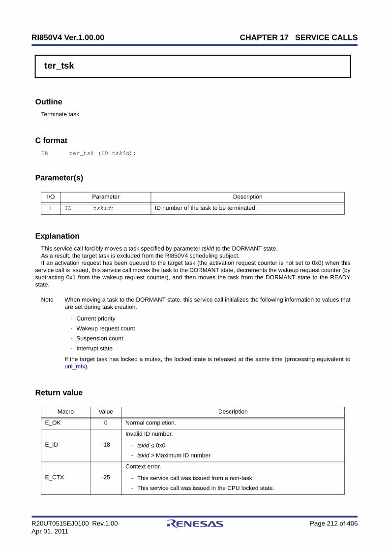
RI850V4 Ver.1.00.00 CHAPTER 17 SERVICE CALLS
R20UT0515EJ0100 Rev.1.00 Page 212 of 406Apr 01, 2011
ter_tsk
Outline
Terminate task.
C format
ER ter_tsk (ID tskid);
Parameter(s)
Explanation
This service call forcibly moves a task specified by parameter tskid to the DORMANT state.As a result, the target task is excluded from the RI850V4 scheduling subject.If an activation request has been queued to the target task (the activation request counter is not set to 0x0) when this
service call is issued, this service call moves the task to the DORMANT state, decrements the wakeup request counter (bysubtracting 0x1 from the wakeup request counter), and then moves the task from the DORMANT state to the READYstate.
Note When moving a task to the DORMANT state, this service call initializes the following information to values thatare set during task creation.
- Current priority
- Wakeup request count
- Suspension count
- Interrupt state
If the target task has locked a mutex, the locked state is released at the same time (processing equivalent tounl_mtx).
Return value
I/O Parameter Description
I ID tskid; ID number of the task to be terminated.
Macro Value Description
E_OK 0 Normal completion.
E_ID -18
Invalid ID number.
- tskid < 0x0
- tskid > Maximum ID number
E_CTX -25
Context error.
- This service call was issued from a non-task.
- This service call was issued in the CPU locked state.

RI850V4 Ver.1.00.00 CHAPTER 17 SERVICE CALLS
R20UT0515EJ0100 Rev.1.00 Page 213 of 406Apr 01, 2011
E_ILUSE -28Illegal service call use.
- Specified task is an invoking task.
E_OBJ -41Object state error.
- Specified task is in the DORMANT state.
E_NOEXS -42Non-existent object.
- Specified task is not registered.
Macro Value Description

RI850V4 Ver.1.00.00 CHAPTER 17 SERVICE CALLS
R20UT0515EJ0100 Rev.1.00 Page 214 of 406Apr 01, 2011
chg_priichg_pri
Outline
Change task priority.
C format
ER chg_pri (ID tskid, PRI tskpri);ER ichg_pri (ID tskid, PRI tskpri);
Parameter(s)
Explanation
These service calls change the priority of the task specified by parameter tskid (current priority) to a value specified byparameter tskpri.
If the target task is in the RUNNING or READY state after this service call is issued, this service call re-queues the taskat the end of the ready queue corresponding to the priority specified by parameter tskpri, following priority changeprocessing.
Note When the target task is queued to a wait queue in the order of priority, the wait order may change due toissuance of this service call.
Example When three tasks (task A: priority level 10, task B: priority level 11, task C: priority level 12) arequeued to the semaphore wait queue in the order of priority, and the priority level of task B ischanged from 11 to 9, the wait order will be changed as follows.
I/O Parameter Description
I ID tskid;
ID number of the task whose priority is to be changed.
TSK_SELF: Invoking task.Value: ID number of the task whose priority is to be changed.
I PRI tskpri;
New base priority of the task.
TPRI_INI: Initial priority.Value: New base priority.
Task CSemaphore
Task ATask B
chg_pri (Task B, 9);
Priority: 9 Priority: 10 Priority: 12
Task CSemaphore
Task BTask APriority: 10 Priority: 11 Priority: 12
Task CPriority: 12
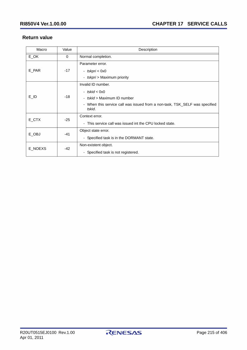
RI850V4 Ver.1.00.00 CHAPTER 17 SERVICE CALLS
R20UT0515EJ0100 Rev.1.00 Page 215 of 406Apr 01, 2011
Return value
Macro Value Description
E_OK 0 Normal completion.
E_PAR -17
Parameter error.
- tskpri < 0x0
- tskpri > Maximum priority
E_ID -18
Invalid ID number.
- tskid < 0x0
- tskid > Maximum ID number
- When this service call was issued from a non-task, TSK_SELF was specifiedtskid.
E_CTX -25Context error.
- This service call was issued int the CPU locked state.
E_OBJ -41Object state error.
- Specified task is in the DORMANT state.
E_NOEXS -42Non-existent object.
- Specified task is not registered.

RI850V4 Ver.1.00.00 CHAPTER 17 SERVICE CALLS
R20UT0515EJ0100 Rev.1.00 Page 216 of 406Apr 01, 2011
get_priiget_pri
Outline
Reference task priority.
C format
ER get_pri (ID tskid, PRI *p_tskpri);ER iget_pri (ID tskid, PRI *p_tskpri);
Parameter(s)
Explanation
Stores current priority of the task specified by parameter tskid in the area specified by parameter p_tskpri.
Return value
I/O Parameter Description
I ID tskid;
ID number of the task to reference.
TSK_SELF: Invoking task.Value: ID number of the task to reference.
O PRI *p_tskpri; Current priority of specified task.
Macro Value Description
E_OK 0 Normal completion.
E_ID -18
Invalid ID number.
- tskid < 0x0
- tskid > Maximum ID number
- When this service call was issued from a non-task, TSK_SELF was specifiedtskid.
E_CTX -25Context error.
- This service call was issued in the CPU locked state.
E_OBJ -41Object state error.
- Specified task is in the DORMANT state.
E_NOEXS -42Non-existent object.
- Specified task is not registered.
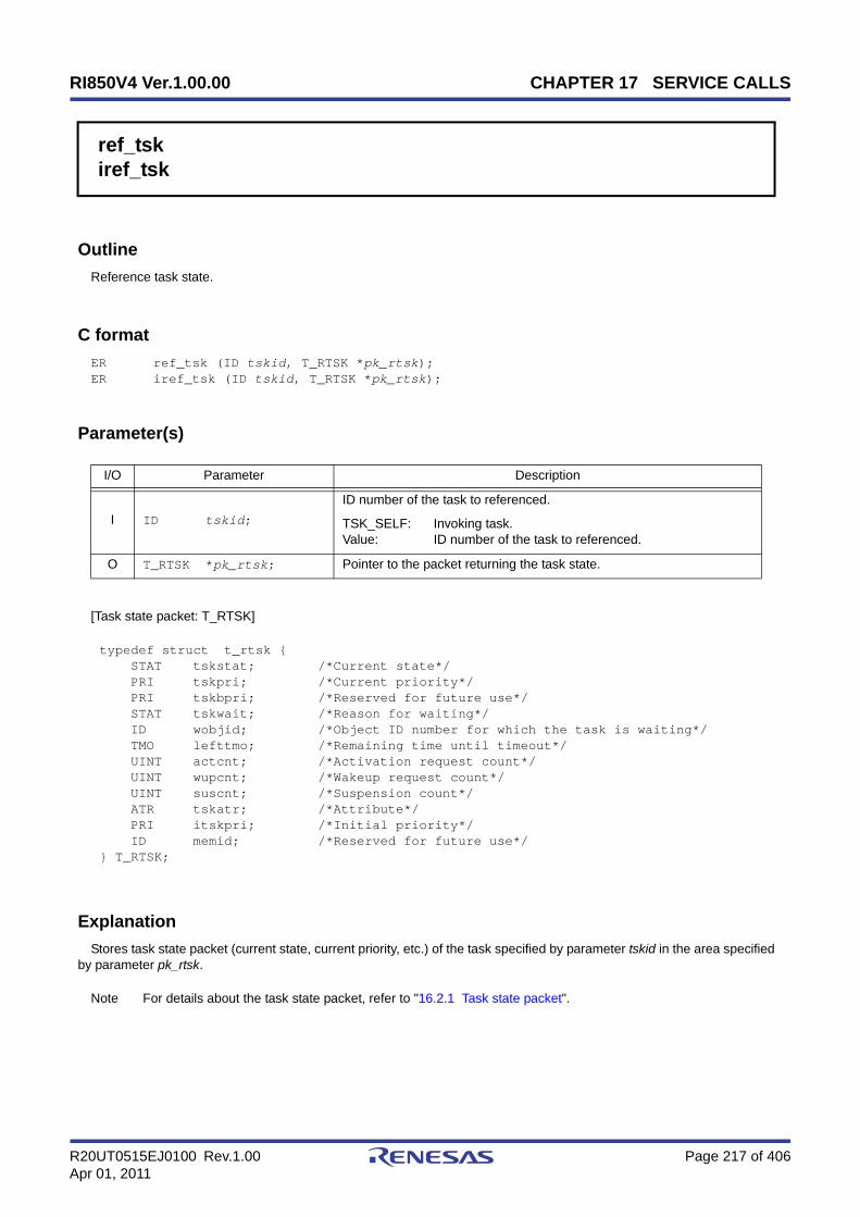
RI850V4 Ver.1.00.00 CHAPTER 17 SERVICE CALLS
R20UT0515EJ0100 Rev.1.00 Page 217 of 406Apr 01, 2011
ref_tskiref_tsk
Outline
Reference task state.
C format
ER ref_tsk (ID tskid, T_RTSK *pk_rtsk);ER iref_tsk (ID tskid, T_RTSK *pk_rtsk);
Parameter(s)
[Task state packet: T_RTSK]
Explanation
Stores task state packet (current state, current priority, etc.) of the task specified by parameter tskid in the area specifiedby parameter pk_rtsk.
Note For details about the task state packet, refer to "16.2.1 Task state packet".
I/O Parameter Description
I ID tskid;
ID number of the task to referenced.
TSK_SELF: Invoking task.Value: ID number of the task to referenced.
O T_RTSK *pk_rtsk; Pointer to the packet returning the task state.
typedef struct t_rtsk { STAT tskstat; /*Current state*/ PRI tskpri; /*Current priority*/ PRI tskbpri; /*Reserved for future use*/ STAT tskwait; /*Reason for waiting*/ ID wobjid; /*Object ID number for which the task is waiting*/ TMO lefttmo; /*Remaining time until timeout*/ UINT actcnt; /*Activation request count*/ UINT wupcnt; /*Wakeup request count*/ UINT suscnt; /*Suspension count*/ ATR tskatr; /*Attribute*/ PRI itskpri; /*Initial priority*/ ID memid; /*Reserved for future use*/} T_RTSK;

RI850V4 Ver.1.00.00 CHAPTER 17 SERVICE CALLS
R20UT0515EJ0100 Rev.1.00 Page 218 of 406Apr 01, 2011
Return value
Macro Value Description
E_OK 0 Normal completion.
E_ID -18
Invalid ID number.
- tskid < 0x0
- tskid > Maximum ID number
- When this service call was issued from a non-task, TSK_SELF was specifiedtskid.
E_CTX -25Context error.
- This service call was issued in the CPU locked state.
E_NOEXS -42Non-Existent object.
- Specified task is not registered.

RI850V4 Ver.1.00.00 CHAPTER 17 SERVICE CALLS
R20UT0515EJ0100 Rev.1.00 Page 219 of 406Apr 01, 2011
ref_tstiref_tst
Outline
Reference task state (simplified version).
C format
ER ref_tst (ID tskid, T_RTST *pk_rtst);ER iref_tst (ID tskid, T_RTST *pk_rtst);
Parameter(s)
[Task state packet (simplified version): T_RTST]
Explanation
Stores task state packet (current state, reason for waiting) of the task specified by parameter tskid in the area specifiedby parameter pk_rtst.
Used for referencing only the current state and reason for wait among task information.Response becomes faster than using ref_tsk or iref_tsk because only a few information items are acquired.
Note For details about the task state packet (simplified version), refer to "16.2.2 Task state packet (simplifiedversion)".
Return value
I/O Parameter Description
I ID tskid;
ID number of the task to be referenced.
TSK_SELF: Invoking task.Value: ID number of the task to be referenced.
O T_RTST *pk_rtst; Pointer to the packet returning the task state.
typedef struct t_rtst { STAT tskstat; /*Current state*/ STAT tskwait; /*Reason for waiting*/} T_RTST;
Macro Value Description
E_OK 0 Normal completion.

RI850V4 Ver.1.00.00 CHAPTER 17 SERVICE CALLS
R20UT0515EJ0100 Rev.1.00 Page 220 of 406Apr 01, 2011
E_ID -18
Invalid ID number.
- tskid < 0x0
- tskid > Maximum ID number
- When this service call was issued from a non-task, TSK_SELF was specifiedtskid.
E_CTX -25Context error.
- This service call was issued in the CPU locked state.
E_NOEXS -42Non-existent object.
- Specified task is not registered.
Macro Value Description
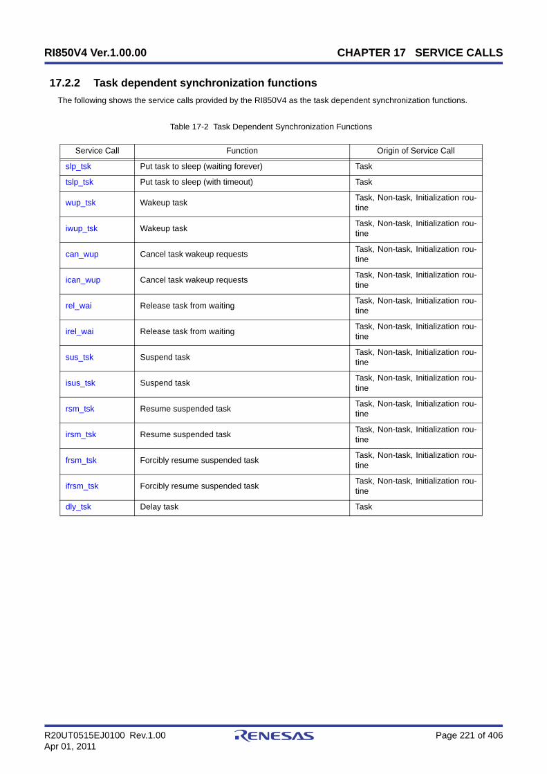
RI850V4 Ver.1.00.00 CHAPTER 17 SERVICE CALLS
R20UT0515EJ0100 Rev.1.00 Page 221 of 406Apr 01, 2011
17.2.2 Task dependent synchronization functions
The following shows the service calls provided by the RI850V4 as the task dependent synchronization functions.
Table 17-2 Task Dependent Synchronization Functions
Service Call Function Origin of Service Call
slp_tsk Put task to sleep (waiting forever) Task
tslp_tsk Put task to sleep (with timeout) Task
wup_tsk Wakeup task Task, Non-task, Initialization rou-tine
iwup_tsk Wakeup task Task, Non-task, Initialization rou-tine
can_wup Cancel task wakeup requests Task, Non-task, Initialization rou-tine
ican_wup Cancel task wakeup requests Task, Non-task, Initialization rou-tine
rel_wai Release task from waiting Task, Non-task, Initialization rou-tine
irel_wai Release task from waiting Task, Non-task, Initialization rou-tine
sus_tsk Suspend task Task, Non-task, Initialization rou-tine
isus_tsk Suspend task Task, Non-task, Initialization rou-tine
rsm_tsk Resume suspended task Task, Non-task, Initialization rou-tine
irsm_tsk Resume suspended task Task, Non-task, Initialization rou-tine
frsm_tsk Forcibly resume suspended task Task, Non-task, Initialization rou-tine
ifrsm_tsk Forcibly resume suspended task Task, Non-task, Initialization rou-tine
dly_tsk Delay task Task
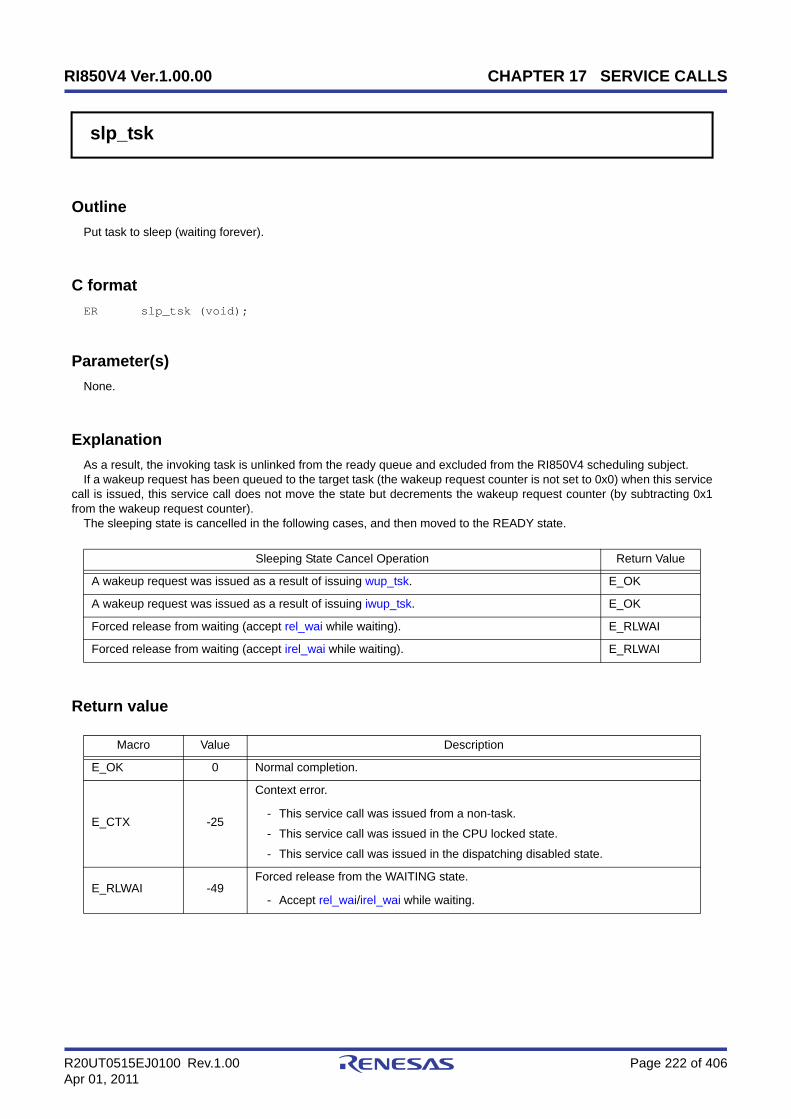
RI850V4 Ver.1.00.00 CHAPTER 17 SERVICE CALLS
R20UT0515EJ0100 Rev.1.00 Page 222 of 406Apr 01, 2011
slp_tsk
Outline
Put task to sleep (waiting forever).
C format
ER slp_tsk (void);
Parameter(s)
None.
Explanation
As a result, the invoking task is unlinked from the ready queue and excluded from the RI850V4 scheduling subject.If a wakeup request has been queued to the target task (the wakeup request counter is not set to 0x0) when this service
call is issued, this service call does not move the state but decrements the wakeup request counter (by subtracting 0x1from the wakeup request counter).
The sleeping state is cancelled in the following cases, and then moved to the READY state.
Return value
Sleeping State Cancel Operation Return Value
A wakeup request was issued as a result of issuing wup_tsk. E_OK
A wakeup request was issued as a result of issuing iwup_tsk. E_OK
Forced release from waiting (accept rel_wai while waiting). E_RLWAI
Forced release from waiting (accept irel_wai while waiting). E_RLWAI
Macro Value Description
E_OK 0 Normal completion.
E_CTX -25
Context error.
- This service call was issued from a non-task.
- This service call was issued in the CPU locked state.
- This service call was issued in the dispatching disabled state.
E_RLWAI -49Forced release from the WAITING state.
- Accept rel_wai/irel_wai while waiting.

RI850V4 Ver.1.00.00 CHAPTER 17 SERVICE CALLS
R20UT0515EJ0100 Rev.1.00 Page 223 of 406Apr 01, 2011
tslp_tsk
Outline
Put task to sleep (with timeout).
C format
ER tslp_tsk (TMO tmout);
Parameter(s)
Explanation
This service call moves an invoking task from the RUNNING state to the WAITING state (sleeping state).As a result, the invoking task is unlinked from the ready queue and excluded from the RI850V4 scheduling subject.If a wakeup request has been queued to the target task (the wakeup request counter is not set to 0x0) when this service
call is issued, this service call does not move the state but decrements the wakeup request counter (by subtracting 0x1from the wakeup request counter).
The sleeping state is cancelled in the following cases, and then moved to the READY state.
Note When TMO_FEVR is specified for wait time tmout, processing equivalent to slp_tsk will be executed.
Return value
I/O Parameter Description
I TMO tmout;
Specified timeout (in millisecond).
TMO_FEVR: Waiting forever.TMO_POL: Polling.Value: Specified timeout.
Sleeping State Cancel Operation Return Value
A wakeup request was issued as a result of issuing wup_tsk. E_OK
A wakeup request was issued as a result of issuing iwup_tsk. E_OK
Forced release from waiting (accept rel_wai while waiting). E_RLWAI
Forced release from waiting (accept irel_wai while waiting). E_RLWAI
Polling failure or timeout. E_TMOUT
Macro Value Description
E_OK 0 Normal completion.
E_PAR -17Parameter error.
- tmout < TMO_FEVR

RI850V4 Ver.1.00.00 CHAPTER 17 SERVICE CALLS
R20UT0515EJ0100 Rev.1.00 Page 224 of 406Apr 01, 2011
E_CTX -25
Context error.
- This service call was issued from a non-task.
- This service call was issued in the CPU locked state.
- This service call was issued in the dispatching disabled state.
E_RLWAI -49Forced release from the WAITING state.
- Accept rel_wai/irel_wai while waiting.
E_TMOUT -50Timeout.
- Polling failure or timeout.
Macro Value Description
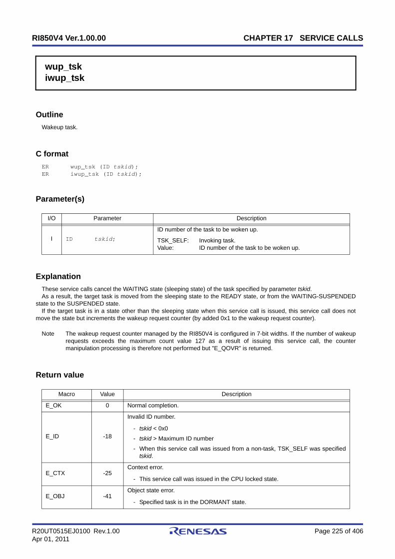
RI850V4 Ver.1.00.00 CHAPTER 17 SERVICE CALLS
R20UT0515EJ0100 Rev.1.00 Page 225 of 406Apr 01, 2011
wup_tskiwup_tsk
Outline
Wakeup task.
C format
ER wup_tsk (ID tskid);ER iwup_tsk (ID tskid);
Parameter(s)
Explanation
These service calls cancel the WAITING state (sleeping state) of the task specified by parameter tskid.As a result, the target task is moved from the sleeping state to the READY state, or from the WAITING-SUSPENDED
state to the SUSPENDED state.If the target task is in a state other than the sleeping state when this service call is issued, this service call does not
move the state but increments the wakeup request counter (by added 0x1 to the wakeup request counter).
Note The wakeup request counter managed by the RI850V4 is configured in 7-bit widths. If the number of wakeuprequests exceeds the maximum count value 127 as a result of issuing this service call, the countermanipulation processing is therefore not performed but "E_QOVR" is returned.
Return value
I/O Parameter Description
I ID tskid;
ID number of the task to be woken up.
TSK_SELF: Invoking task.Value: ID number of the task to be woken up.
Macro Value Description
E_OK 0 Normal completion.
E_ID -18
Invalid ID number.
- tskid < 0x0
- tskid > Maximum ID number
- When this service call was issued from a non-task, TSK_SELF was specifiedtskid.
E_CTX -25Context error.
- This service call was issued in the CPU locked state.
E_OBJ -41Object state error.
- Specified task is in the DORMANT state.

RI850V4 Ver.1.00.00 CHAPTER 17 SERVICE CALLS
R20UT0515EJ0100 Rev.1.00 Page 226 of 406Apr 01, 2011
E_NOEXS -42Non-existent object.
- Specified task is not registered.
E_QOVR -43Queue overflow.
- Wakeup request count exceeded 127.
Macro Value Description

RI850V4 Ver.1.00.00 CHAPTER 17 SERVICE CALLS
R20UT0515EJ0100 Rev.1.00 Page 227 of 406Apr 01, 2011
can_wupican_wup
Outline
Cancel task wakeup requests.
C format
ER_UINT can_wup (ID tskid);ER_UINT ican_wup (ID tskid);
Parameter(s)
Explanation
These service calls cancel all of the wakeup requests queued to the task specified by parameter tskid (the wakeuprequest counter is set to 0x0).
When this service call is terminated normally, the number of cancelled wakeup requests is returned.
Return value
I/O Parameter Description
I ID tskid;
ID number of the task for cancelling wakeup requests.
TSK_SELF: Invoking task.Value: ID number of the task for cancelling wakeup requests.
Macro Value Description
E_ID -18
Invalid ID number.
- tskid < 0x0
- tskid > Maximum ID number
- When this service call was issued from a non-task, TSK_SELF was specifiedtskid.
E_CTX -25Context error.
- This service call was issued in the CPU locked state.
E_OBJ -41Object state error.
- Specified task is in the DORMANT state.
E_NOEXS -42Non-existent object.
- Specified task is not registered.
- - Normal completion (wakeup request count).
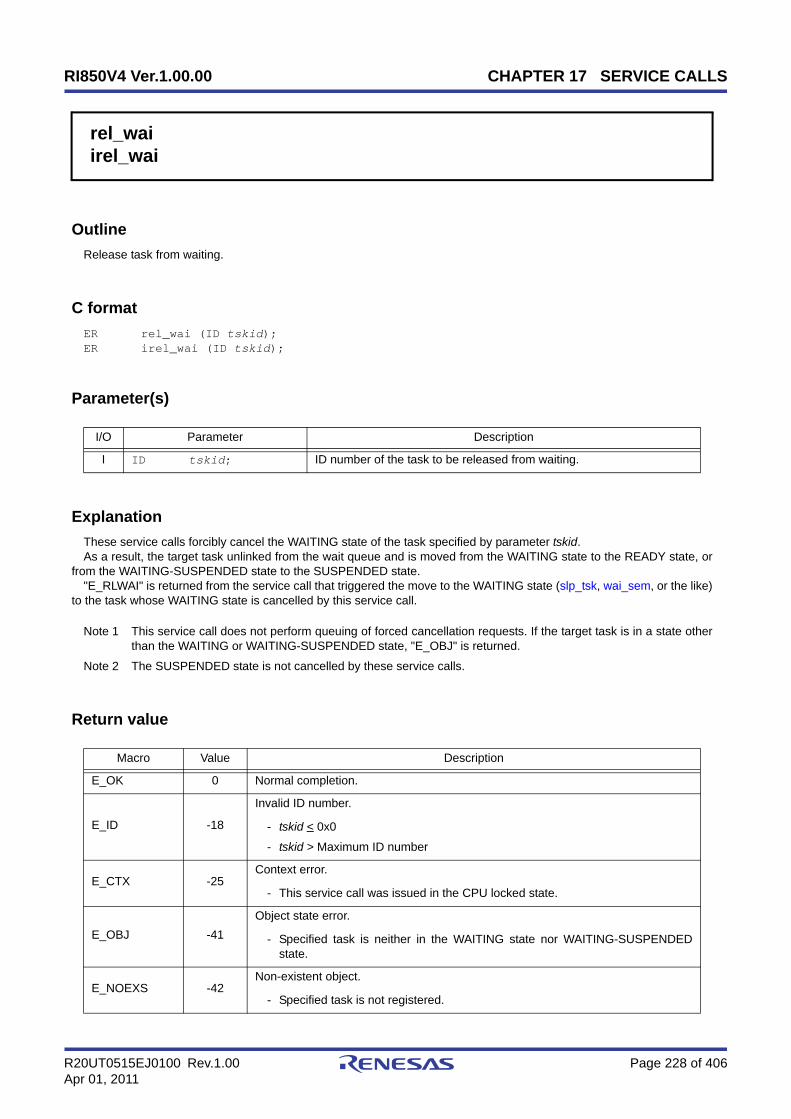
RI850V4 Ver.1.00.00 CHAPTER 17 SERVICE CALLS
R20UT0515EJ0100 Rev.1.00 Page 228 of 406Apr 01, 2011
rel_waiirel_wai
Outline
Release task from waiting.
C format
ER rel_wai (ID tskid);ER irel_wai (ID tskid);
Parameter(s)
Explanation
These service calls forcibly cancel the WAITING state of the task specified by parameter tskid.As a result, the target task unlinked from the wait queue and is moved from the WAITING state to the READY state, or
from the WAITING-SUSPENDED state to the SUSPENDED state."E_RLWAI" is returned from the service call that triggered the move to the WAITING state (slp_tsk, wai_sem, or the like)
to the task whose WAITING state is cancelled by this service call.
Note 1 This service call does not perform queuing of forced cancellation requests. If the target task is in a state otherthan the WAITING or WAITING-SUSPENDED state, "E_OBJ" is returned.
Note 2 The SUSPENDED state is not cancelled by these service calls.
Return value
I/O Parameter Description
I ID tskid; ID number of the task to be released from waiting.
Macro Value Description
E_OK 0 Normal completion.
E_ID -18
Invalid ID number.
- tskid < 0x0
- tskid > Maximum ID number
E_CTX -25Context error.
- This service call was issued in the CPU locked state.
E_OBJ -41Object state error.
- Specified task is neither in the WAITING state nor WAITING-SUSPENDEDstate.
E_NOEXS -42Non-existent object.
- Specified task is not registered.

RI850V4 Ver.1.00.00 CHAPTER 17 SERVICE CALLS
R20UT0515EJ0100 Rev.1.00 Page 229 of 406Apr 01, 2011
sus_tskisus_tsk
Outline
Suspend task.
C format
ER sus_tsk (ID tskid);ER isus_tsk (ID tskid);
Parameter(s)
Explanation
These service calls add 0x1 to the suspend request counter for the task specified by parameter tskid, and then move thetarget task from the RUNNING state to the SUSPENDED state, from the READY state to the SUSPENDED state, or fromthe WAITING state to the WAITING-SUSPENDED state.
If the target task has moved to the SUSPENDED or WAITING-SUSPENDED state when this service call is issued, thecounter manipulation processing is not performed but only the suspend request counter increment processing is executed.
Note The suspend request counter managed by the RI850V4 is configured in 7-bit widths. If the number of suspendrequests exceeds the maximum count value 127 as a result of issuing this service call, the countermanipulation processing is therefore not performed but "E_QOVR" is returned.
Return value
I/O Parameter Description
I ID tskid;
ID number of the task to be suspended.
TSK_SELF: Invoking task.Value: ID number of the task to be suspended.
Macro Value Description
E_OK 0 Normal completion.
E_ID -18
Invalid ID number.
- tskid < 0x0
- tskid > Maximum ID number
- When this service call was issued from a non-task, TSK_SELF was specifiedtskid.
E_CTX -25
Context error.
- This service call was issued in the CPU locked state.
- When this service call was issued in the dispatching disabled state, invokingtask was specified tskid.

RI850V4 Ver.1.00.00 CHAPTER 17 SERVICE CALLS
R20UT0515EJ0100 Rev.1.00 Page 230 of 406Apr 01, 2011
E_OBJ -41Object state error.
- Specified task is in the DORMANT state.
E_NOEXS -42Non-existent object.
- Specified task is not registered.
E_QOVR -43Queue overflow.
- Suspension count exceeded 127.
Macro Value Description

RI850V4 Ver.1.00.00 CHAPTER 17 SERVICE CALLS
R20UT0515EJ0100 Rev.1.00 Page 231 of 406Apr 01, 2011
rsm_tskirsm_tsk
Outline
Resume suspended task.
C format
ER rsm_tsk (ID tskid);ER irsm_tsk (ID tskid);
Parameter(s)
Explanation
This service call subtracts 0x1 from the suspend request counter for the task specified by parameter tskid, and thencancels the SUSPENDED state of the target task.
As a result, the target task is moved from the SUSPENDED state to the READY state, or from the WAITING-SUSPENDED state to the WAITING state.
If a suspend request is queued (subtraction result is other than 0x0) when this service call is issued, the countermanipulation processing is not performed but only the suspend request counter decrement processing is executed.
Note This service call does not perform queuing of cancellation requests. If the target task is in a state other than theSUSPENDED or WAITING-SUSPENDED state, "E_OBJ" is therefore returned.
Return value
I/O Parameter Description
I ID tskid; ID number of the task to be resumed.
Macro Value Description
E_OK 0 Normal completion.
E_ID -18
Invalid ID number.
- tskid < 0x0
- tskid > Maximum ID number
E_CTX -25Context error.
- This service call was issued in the CPU locked state.
E_OBJ -41Object state error.
- Specified task is neither in the SUSPENDED state nor WAITING-SUSPENDED state.
E_NOEXS -42Non-existent object.
- Specified task is not registered.

RI850V4 Ver.1.00.00 CHAPTER 17 SERVICE CALLS
R20UT0515EJ0100 Rev.1.00 Page 232 of 406Apr 01, 2011
frsm_tskifrsm_tsk
Outline
Forcibly resume suspended task.
C format
ER frsm_tsk (ID tskid);ER ifrsm_tsk (ID tskid);
Parameter(s)
Explanation
These service calls cancel all of the suspend requests issued for the task specified by parameter tskid (by setting thesuspend request counter to 0x0). As a result, the target task moves from the SUSPENDED state to the READY state, orfrom the WAITING-SUSPENDED state to the WAITING state.
Note This service call does not perform queuing of cancellation requests. If the target task is in a state other than theSUSPENDED or WAITING-SUSPENDED state, "E_OBJ" is therefore returned.
Return value
I/O Parameter Description
I ID tskid; ID number of the task to be resumed.
Macro Value Description
E_OK 0 Normal completion.
E_ID -18
Invalid ID number.
- tskid < 0x0
- tskid > Maximum ID number
E_CTX -25Context error.
- This service call was issued in the CPU locked state.
E_OBJ -41Object state error.
- Specified task is neither in the SUSPENDED state nor WAITING-SUSPENDED state.
E_NOEXS -42Non-existent object.
- Specified task is not registered.

RI850V4 Ver.1.00.00 CHAPTER 17 SERVICE CALLS
R20UT0515EJ0100 Rev.1.00 Page 233 of 406Apr 01, 2011
dly_tsk
Outline
Delay task.
C format
ER dly_tsk (RELTIM dlytim);
Parameter(s)
Explanation
This service call moves the invoking task from the RUNNING state to the WAITING state (delayed state).As a result, the invoking task is unlinked from the ready queue and excluded from the RI850V4 scheduling subject.The delayed state is cancelled in the following cases, and then moved to the READY state.
Return value
I/O Parameter Description
I RELTIM dlytim; Amount of time to delay the invoking task (in millisecond).
Delayed State Cancel Operation Return Value
Delay time specified by parameter dlytim has elapsed. E_OK
Forced release from waiting (accept rel_wai while waiting). E_RLWAI
Forced release from waiting (accept irel_wai while waiting). E_RLWAI
Macro Value Description
E_OK 0 Normal completion.
E_CTX -25
Context error.
- This service call was issued from a non-task.
- This service call was issued in the CPU locked state.
- This service call was issued in the dispatching disabled state.
E_RLWAI -49Forced release from the WAITING state.
- Accept rel_wai/irel_wai while waiting.
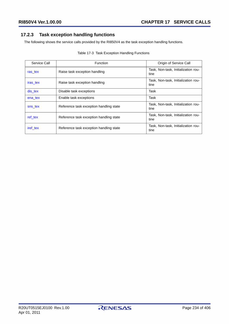
RI850V4 Ver.1.00.00 CHAPTER 17 SERVICE CALLS
R20UT0515EJ0100 Rev.1.00 Page 234 of 406Apr 01, 2011
17.2.3 Task exception handling functions
The following shows the service calls provided by the RI850V4 as the task exception handling functions.
Table 17-3 Task Exception Handling Functions
Service Call Function Origin of Service Call
ras_tex Raise task exception handling Task, Non-task, Initialization rou-tine
iras_tex Raise task exception handling Task, Non-task, Initialization rou-tine
dis_tex Disable task exceptions Task
ena_tex Enable task exceptions Task
sns_tex Reference task exception handling state Task, Non-task, Initialization rou-tine
ref_tex Reference task exception handling state Task, Non-task, Initialization rou-tine
iref_tex Reference task exception handling state Task, Non-task, Initialization rou-tine

RI850V4 Ver.1.00.00 CHAPTER 17 SERVICE CALLS
R20UT0515EJ0100 Rev.1.00 Page 235 of 406Apr 01, 2011
ras_texiras_tex
Outline
Raise task exception handling.
C format
ER ras_tex (ID tskid, TEXPTN rasptn);ER iras_tex (ID tskid, TEXPTN rasptn);
Parameter(s)
Explanation
These service calls issue a task exception handling request for the task specified by parameter tskid. As a result, thetask exception handling routine registered to the target task is activated when the target task moves to the RUNNINGstate.
For parameter rasptn, specify the task exception code to be passed to the target task exception handling routine. Thetarget task exception handling routine can then be manipulatable by handling the task exception code as a functionparameter.
Note These service calls do not perform queuing of task exception handling requests. If a task exception handlingrequest is issued multiple times before a task exception handling routine is activated (from when a taskexception handling request is issued until the target task moves to the RUNNING state), the task exceptionhandling request will not be issued after the second and later issuance of these service calls, but the taskexception code is just held pending (OR of task exception codes).
Return value
I/O Parameter Description
I ID tskid;
ID number of the task requested.
TSK_SELF: Invoking task.Value: ID number of the task requested.
I TEXPTN rasptn; Task exception code to be requested.
Macro Value Description
E_OK 0 Normal completion.
E_PAR -17Parameter error.
- rasptn = 0x0
E_ID -18
Invalid ID number.
- tskid < 0x0
- tskid > Maximum ID number
- When this service call was issued from a non-task, TSK_SELF was specifiedtskid.

RI850V4 Ver.1.00.00 CHAPTER 17 SERVICE CALLS
R20UT0515EJ0100 Rev.1.00 Page 236 of 406Apr 01, 2011
E_CTX -25Context error.
- This service call was issued in the CPU locked state.
E_OBJ -41
Ojbect state error.
- Specified task is in the DORMANT state.
- Task exception handling routine is not defined.
E_NOEXS -42Non-existent object.
- Specified task is not registered.
Macro Value Description

RI850V4 Ver.1.00.00 CHAPTER 17 SERVICE CALLS
R20UT0515EJ0100 Rev.1.00 Page 237 of 406Apr 01, 2011
dis_tex
Outline
Disable task exceptions.
C format
ER dis_tex (void);
Parameter(s)
None.
Explanation
This service call moves a task exception handling routine, which is registered to an invoking task, from the enabled stateto disabled state. As a result, the target task exception handling routine is excluded from the activation targets of theRI850V4 from when this service call is issued until ena_tex is issued.
If a task exception handling request (ras_tex or iras_tex) is issued from when this service call is issued until ena_tex isissued, the RI850V4 only performs processing such as acknowledgment of task exception handling requests and theactual activation processing is delayed until the target task exception handling routine moves to the task exceptionhandling enabled state.
Note 1 This service call does not perform queuing of disable requests. If the target task exception handling routine hasbeen moved to the task exception handling disabled state, therefore, no processing is performed but it is nothandled as an error.
Note 2 In the RI850V4, task exception handling is disabled when a task is activated.
Return value
Macro Value Description
E_OK 0 Normal completion.
E_CTX -25
Context error.
- This service call was issued from a non-task.
- This service call was issued in the CPU locked state.
E_OBJ -41Object state error.
- Task exception handling routine is not defined.

RI850V4 Ver.1.00.00 CHAPTER 17 SERVICE CALLS
R20UT0515EJ0100 Rev.1.00 Page 238 of 406Apr 01, 2011
ena_tex
Outline
Enable task exceptions.
C format
ER ena_tex (void);
Parameter(s)
None.
Explanation
This service call moves a task exception handling routine, which is registered to an invoking task, from the disabledstate to enabled state. As a result, the target task exception handling routine becomes the activation target of theRI850V4.
If a task exception handling request (ras_tex or iras_tex) is issued from when dis_tex is issued until this service call isissued, the RI850V4 only performs processing such as acknowledgment of task exception handling requests and theactual activation processing is delayed until the target task exception handling routine moves to the task exceptionhandling enabled state.
Note This service call does not perform queuing of activation requests. If the target task exception handling routinehas been moved to the task exception handling enabled state, therefore, no processing is performed but it isnot handled as an error.
Return value
Macro Value Description
E_OK 0 Normal completion.
E_CTX -25
Context error.
- This service call was issued from a non-task.
- This service call was issued in the CPU locked state.
E_OBJ -41Object state error.
- Task exception handling routine is not defined.
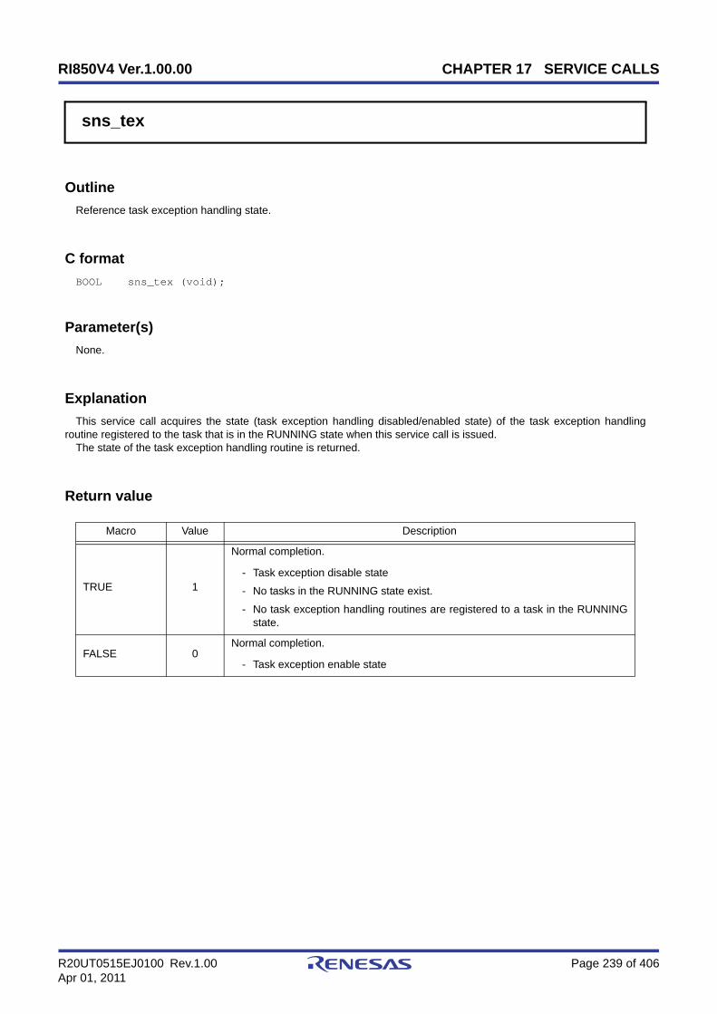
RI850V4 Ver.1.00.00 CHAPTER 17 SERVICE CALLS
R20UT0515EJ0100 Rev.1.00 Page 239 of 406Apr 01, 2011
sns_tex
Outline
Reference task exception handling state.
C format
BOOL sns_tex (void);
Parameter(s)
None.
Explanation
This service call acquires the state (task exception handling disabled/enabled state) of the task exception handlingroutine registered to the task that is in the RUNNING state when this service call is issued.
The state of the task exception handling routine is returned.
Return value
Macro Value Description
TRUE 1
Normal completion.
- Task exception disable state
- No tasks in the RUNNING state exist.
- No task exception handling routines are registered to a task in the RUNNINGstate.
FALSE 0Normal completion.
- Task exception enable state

RI850V4 Ver.1.00.00 CHAPTER 17 SERVICE CALLS
R20UT0515EJ0100 Rev.1.00 Page 240 of 406Apr 01, 2011
ref_texiref_tex
Outline
Reference task exception handling state.
C format
ER ref_tex (ID tskid, T_RTEX *pk_rtex);ER iref_tex (ID tskid, T_RTEX *pk_rtex);
Parameter(s)
[Task exception handling routine state packet: T_RTEX]
Explanation
These service calls store the detailed information (current status, pending exception code, etc.) of the task exceptionhandling routine registered to the task specified by parameter tskid into the area specified by parameter pk_rtex.
E_OBJ is returned if no task exception handling routines are registered to the specified task.
Note For details about the task exception handling routine state packet, refer to "16.2.3 Task exception handlingroutine state packet".
Return value
I/O Parameter Description
I ID tskid;
ID number of the task to be referenced.
TSK_SELF: Invoking task.Value: ID number of the task to be referenced.
O T_RTEX *pk_rtex; Pointer to the packet returning the task exception handling state.
typedef struct t_rtex { STAT texstat; /*Current state*/ TEXPTN pndptn; /*Pending exception code*/ ATR texatr; /*Attribute*/} T_RTEX;
Macro Value Description
E_OK 0 Normal completion.

RI850V4 Ver.1.00.00 CHAPTER 17 SERVICE CALLS
R20UT0515EJ0100 Rev.1.00 Page 241 of 406Apr 01, 2011
E_ID -18
Invalid ID number.
- tskid < 0x0
- tskid > Maximum ID number
- When this service call was issued from a non-task, TSK_SELF was specifiedtskid.
E_CTX -25Context error.
- This service call was issued in the CPU locked state.
E_OBJ -41
Object state error.
- Specified task is in the DORMANT state.
- Task exception handling routine is not defined.
E_NOEXS -42Non-existent object.
- Specified task is not registered.
Macro Value Description

RI850V4 Ver.1.00.00 CHAPTER 17 SERVICE CALLS
R20UT0515EJ0100 Rev.1.00 Page 242 of 406Apr 01, 2011
17.2.4 Synchronization and communication functions (semaphores)
The following shows the service calls provided by the RI850V4 as the synchronization and communication functions(semaphores).
Table 17-4 Synchronization and Communication Functions (Semaphores)
Service Call Function Origin of Service Call
wai_sem Acquire semaphore resource (waiting forever) Task
pol_sem Acquire semaphore resource (polling) Task, Non-task, Initialization rou-tine
ipol_sem Acquire semaphore resource (polling) Task, Non-task, Initialization rou-tine
twai_sem Acquire semaphore resource (with timeout) Task
sig_sem Release semaphore resource Task, Non-task, Initialization rou-tine
isig_sem Release semaphore resource Task, Non-task, Initialization rou-tine
ref_sem Reference semaphore state Task, Non-task, Initialization rou-tine
iref_sem Reference semaphore state Task, Non-task, Initialization rou-tine

RI850V4 Ver.1.00.00 CHAPTER 17 SERVICE CALLS
R20UT0515EJ0100 Rev.1.00 Page 243 of 406Apr 01, 2011
wai_sem
Outline
Acquire semaphore resource (waiting forever).
C format
ER wai_sem (ID semid);
Parameter(s)
Explanation
This service call acquires a resource from the semaphore specified by parameter semid (subtracts 0x1 from thesemaphore counter).
If no resources are acquired from the target semaphore when this service call is issued (no available resources exist),this service call does not acquire resources but queues the invoking task to the target semaphore wait queue and moves itfrom the RUNNING state to the WAITING state (resource acquisition wait state).
The WAITING state for a semaphore resource is cancelled in the following cases, and then moved to the READY state.
Note Invoking tasks are queued to the target semaphore wait queue in the order defined during configuration (FIFOorder or priority order).
Return value
I/O Parameter Description
I ID semid; ID number of the semaphore from which resource is acquired.
WAITING State for a Semaphore Resource Cancel Operation Return Value
The resource was returned to the target semaphore as a result of issuing sig_sem. E_OK
The resource was returned to the target semaphore as a result of issuing isig_sem. E_OK
Forced release from waiting (accept rel_wai while waiting). E_RLWAI
Forced release from waiting (accept irel_wai while waiting). E_RLWAI
Macro Value Description
E_OK 0 Normal completion.
E_ID -18
Invalid ID number.
- semid < 0x0
- semid > Maximum ID number
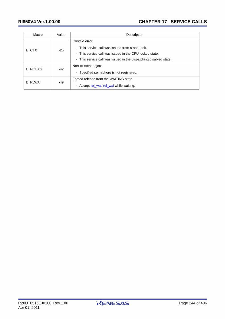
RI850V4 Ver.1.00.00 CHAPTER 17 SERVICE CALLS
R20UT0515EJ0100 Rev.1.00 Page 244 of 406Apr 01, 2011
E_CTX -25
Context error.
- This service call was issued from a non-task.
- This service call was issued in the CPU locked state.
- This service call was issued in the dispatching disabled state.
E_NOEXS -42Non-existent object.
- Specified semaphore is not registered.
E_RLWAI -49Forced release from the WAITING state.
- Accept rel_wai/irel_wai while waiting.
Macro Value Description

RI850V4 Ver.1.00.00 CHAPTER 17 SERVICE CALLS
R20UT0515EJ0100 Rev.1.00 Page 245 of 406Apr 01, 2011
pol_semipol_sem
Outline
Acquire semaphore resource (polling).
C fomrat
ER pol_sem (ID semid);ER isem_sem (ID semid);
Parameter(s)
Explanation
This service call acquires a resource from the semaphore specified by parameter semid (subtracts 0x1 from thesemaphore counter).
If a resource could not be acquired from the target semaphore (semaphore counter is set to 0x0) when this service callis issued, the counter manipulation processing is not performed but "E_TMOUT" is returned.
Return value
I/O Parameter Description
I ID semid; ID number of the semaphore from which resource is acquired.
Macro Value Description
E_OK 0 Normal completion.
E_ID -18
Invalid ID number.
- semid < 0x0
- semid > Maximum ID number
E_CTX -25Context error.
- This service call was issued in the CPU locked state.
E_NOEXS -42Non-existent object.
- Specified semaphore is not registered.
E_TMOUT -50Polling failure.
- The resource counter of the target semaphore is 0x0.
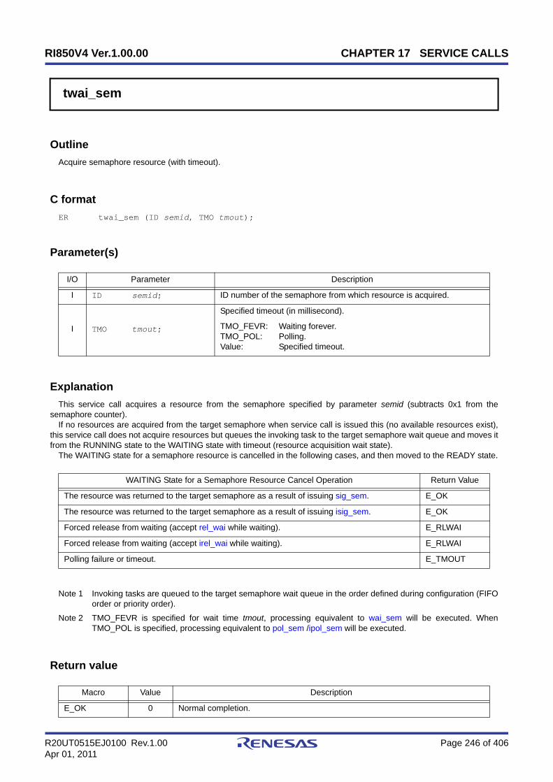
RI850V4 Ver.1.00.00 CHAPTER 17 SERVICE CALLS
R20UT0515EJ0100 Rev.1.00 Page 246 of 406Apr 01, 2011
twai_sem
Outline
Acquire semaphore resource (with timeout).
C format
ER twai_sem (ID semid, TMO tmout);
Parameter(s)
Explanation
This service call acquires a resource from the semaphore specified by parameter semid (subtracts 0x1 from thesemaphore counter).
If no resources are acquired from the target semaphore when service call is issued this (no available resources exist),this service call does not acquire resources but queues the invoking task to the target semaphore wait queue and moves itfrom the RUNNING state to the WAITING state with timeout (resource acquisition wait state).
The WAITING state for a semaphore resource is cancelled in the following cases, and then moved to the READY state.
Note 1 Invoking tasks are queued to the target semaphore wait queue in the order defined during configuration (FIFOorder or priority order).
Note 2 TMO_FEVR is specified for wait time tmout, processing equivalent to wai_sem will be executed. WhenTMO_POL is specified, processing equivalent to pol_sem /ipol_sem will be executed.
Return value
I/O Parameter Description
I ID semid; ID number of the semaphore from which resource is acquired.
I TMO tmout;
Specified timeout (in millisecond).
TMO_FEVR: Waiting forever.TMO_POL: Polling.Value: Specified timeout.
WAITING State for a Semaphore Resource Cancel Operation Return Value
The resource was returned to the target semaphore as a result of issuing sig_sem. E_OK
The resource was returned to the target semaphore as a result of issuing isig_sem. E_OK
Forced release from waiting (accept rel_wai while waiting). E_RLWAI
Forced release from waiting (accept irel_wai while waiting). E_RLWAI
Polling failure or timeout. E_TMOUT
Macro Value Description
E_OK 0 Normal completion.

RI850V4 Ver.1.00.00 CHAPTER 17 SERVICE CALLS
R20UT0515EJ0100 Rev.1.00 Page 247 of 406Apr 01, 2011
E_PAR -17Parameter error.
- tmout < TMO_FEVR
E_ID -18
Invalid ID number.
- semid < 0x0
- semid > Maximum ID number
E_CTX -25
Context error.
- This service call was issued from a non-task.
- This service call was issued in the CPU locked state.
- This service call was issued in the dispatching disabled state.
E_NOEXS -42Non-existent object.
- Specified semaphore is not registered.
E_RLWAI -49Forced release from the WAITING state.
- Accept rel_wai/irel_wai while waiting.
E_TMOUT -50Timeout.
- Polling failure or timeout.
Macro Value Description

RI850V4 Ver.1.00.00 CHAPTER 17 SERVICE CALLS
R20UT0515EJ0100 Rev.1.00 Page 248 of 406Apr 01, 2011
sig_semisig_sem
Outline
Release semaphore resource.
C format
ER sig_sem (ID semid);ER isig_sem (ID semid);
Parameter(s)
Explanation
These service calls return the resource to the semaphore specified by parameter semid (adds 0x1 to the semaphorecounter).
If a task is queued in the wait queue of the target semaphore when this service call is issued, the counter manipulationprocessing is not performed but the resource is passed to the relevant task (first task of wait queue).
As a result, the relevant task is unlinked from the wait queue and is moved from the WAITING state (WAITING state fora semaphore resource) to the READY state, or from the WAITING-SUSPENDED state to the SUSPENDED state.
Note With the RI850V4, the maximum possible number of semaphore resources (maximum resource count) isdefined during configuration. If the number of resources exceeds the specified maximum resource count, thisservice call therefore does not return the acquired resources (addition to the semaphore counter value) butreturns E_QOVR.
Return value
I/O Parameter Description
I ID semid; ID number of the semaphore to which resource is released.
Macro Value Description
E_OK 0 Normal completion.
E_ID -18
Invalid ID number.
- semid < 0x0
- semid > Maximum ID number
E_CTX -25Context error.
- This service call was issued in the CPU locked state.
E_NOEXS -42Non-existent object.
- Specified semaphore is not registered.
E_QOVR -43Queue overflow.
- Resource count exceeded maximum resource count.

RI850V4 Ver.1.00.00 CHAPTER 17 SERVICE CALLS
R20UT0515EJ0100 Rev.1.00 Page 249 of 406Apr 01, 2011
ref_semiref_sem
Outline
Reference semaphore state.
C format
ER ref_sem (ID semid, T_RSEM *pk_rsem);ER iref_sem (ID semid, T_RSEM *pk_rsem);
Parameter(s)
[Semaphore state packet: T_RSEM]
Explanation
Stores semaphore state packet (ID number of the task at the head of the wait queue, current resource count, etc.) of thesemaphore specified by parameter semid in the area specified by parameter pk_rsem.
Note For details about the semaphore state packet, refer to "16.2.4 Semaphore state packet".
Return value
I/O Parameter Description
I ID semid; ID number of the semaphore to be referenced.
O T_RSEM *pk_rsem; Pointer to the packet returning the semaphore state.
typedef struct t_rsem { ID wtskid; /*Existence of waiting task*/ UINT semcnt; /*Current resource count*/ ATR sematr; /*Attribute*/ UINT maxsem; /*Maximum resource count*/} T_RSEM;
Macro Value Description
E_OK 0 Normal completion.
E_ID -18
Invalid ID number.
- semid < 0x0
- semid > Maximum ID number
E_CTX -25Context error.
- This service call was issued in the CPU locked state.

RI850V4 Ver.1.00.00 CHAPTER 17 SERVICE CALLS
R20UT0515EJ0100 Rev.1.00 Page 250 of 406Apr 01, 2011
E_NOEXS -42Non-existent object.
- Specified semaphore is not registered.
Macro Value Description
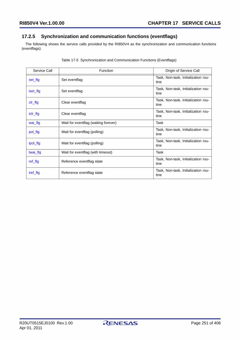
RI850V4 Ver.1.00.00 CHAPTER 17 SERVICE CALLS
R20UT0515EJ0100 Rev.1.00 Page 251 of 406Apr 01, 2011
17.2.5 Synchronization and communication functions (eventflags)
The following shows the service calls provided by the RI850V4 as the synchronization and communication functions(eventflags).
Table 17-5 Synchronization and Communication Functions (Eventflags)
Service Call Function Origin of Service Call
set_flg Set eventflag Task, Non-task, Initialization rou-tine
iset_flg Set eventflag Task, Non-task, Initialization rou-tine
clr_flg Clear eventflag Task, Non-task, Initialization rou-tine
iclr_flg Clear eventflag Task, Non-task, Initialization rou-tine
wai_flg Wait for eventflag (waiting forever) Task
pol_flg Wait for eventflag (polling) Task, Non-task, Initialization rou-tine
ipol_flg Wait for eventflag (polling) Task, Non-task, Initialization rou-tine
twai_flg Wait for eventflag (with timeout) Task
ref_flg Reference eventflag state Task, Non-task, Initialization rou-tine
iref_flg Reference eventflag state Task, Non-task, Initialization rou-tine

RI850V4 Ver.1.00.00 CHAPTER 17 SERVICE CALLS
R20UT0515EJ0100 Rev.1.00 Page 252 of 406Apr 01, 2011
set_flgiset_flg
Outline
Set eventflag.
C format
ER set_flg (ID flgid, FLGPTN setptn);ER iset_flg (ID flgid, FLGPTN setptn);
Parameter(s)
Explanation
These service calls set the result of ORing the bit pattern of the eventflag specified by parameter flgid and the bit patternspecified by parameter setptn as the bit pattern of the target eventflag.
If the required condition of the task queued to the target eventflag wait queue is satisfied when this service call is issued,the relevant task is unlinked from the wait queue at the same time as bit pattern setting processing.
As a result, the relevant task is moved from the WAITING state (WAITING state for an eventflag) to the READY state, orfrom the WAITING-SUSPENDED state to the SUSPENDED state.
Note If the bit pattern set to the target eventflag is B'1100 and the bit pattern specified by parameter setptn is B'1010when this service call is issued, the bit pattern of the target eventflag is set to B'1110.
Return value
I/O Parameter Description
I ID flgid; ID number of the eventflag to be set.
I FLGPTN setptn; Bit pattern to set.
Macro Value Description
E_OK 0 Normal completion.
E_ID -18
Invalid ID number.
- flgid < 0x0
- flgid > Maximum ID number
E_CTX -25Context error.
- This service call was issued in the CPU locked state.
E_NOEXS -42Non-existent object.
- Specified eventflag is not registered.

RI850V4 Ver.1.00.00 CHAPTER 17 SERVICE CALLS
R20UT0515EJ0100 Rev.1.00 Page 253 of 406Apr 01, 2011
clr_flgiclr_flg
Outline
Clear eventflag.
C fomrat
ER clr_flg (ID flgid, FLGPTN clrptn);ER iclr_flg (ID flgid, FLGPTN clrptn);
Parameter(s)
Explanation
This service call sets the result of ANDing the bit pattern set to the eventflag specified by parameter flgid and the bitpattern specified by parameter clrptn as the bit pattern of the target eventflag.
Note If the bit pattern set to the target eventflag is B'1100 and the bit pattern specified by parameter clrptn is B'1010when this service call is issued, the bit pattern of the target eventflag is set to B'1110.
Return value
I/O Parameter Description
I ID flgid; ID number of the eventflag to be cleared.
I FLGPTN clrptn; Bit pattern to clear.
Macro Value Description
E_OK 0 Normal completion.
E_ID -18
Invalid ID number.
- flgid < 0x0
- flgid > Maximum ID number
E_CTX -25Context error.
- This service call was issued in the CPU locked state.
E_NOEXS -42Non-existent object.
- Specified eventflag is not registered.

RI850V4 Ver.1.00.00 CHAPTER 17 SERVICE CALLS
R20UT0515EJ0100 Rev.1.00 Page 254 of 406Apr 01, 2011
wai_flg
Outline
Wait for eventflag (waiting forever).
C format
ER wai_flg (ID flgid, FLGPTN waiptn, MODE wfmode, FLGPTN *p_flgptn);
Parameter(s)
Explanation
This service call checks whether the bit pattern specified by parameter waiptn and the bit pattern that satisfies therequired condition specified by parameter wfmode are set to the eventflag specified by parameter flgid.
If a bit pattern that satisfies the required condition has been set for the target eventflag, the bit pattern of the targeteventflag is stored in the area specified by parameter p_flgptn.
If the bit pattern of the target eventflag does not satisfy the required condition when this service call is issued, theinvoking task is queued to the target eventflag wait queue.
As a result, the invoking task is unlinked from the ready queue and is moved from the RUNNING state to the WAITINGstate (WAITING state for an eventflag).
The WAITING state for an eventflag is cancelled in the following cases, and then moved to the READY state.
The following shows the specification format of required condition wfmode.
- wfmode = TWF_ANDWChecks whether all of the bits to which 1 is set by parameter waiptn are set as the target eventflag.
- wfmode = TWF_ORWChecks which bit, among bits to which 1 is set by parameter waiptn, is set as the target eventflag.
I/O Parameter Description
I ID flgid; ID number of the eventflag to wait for.
I FLGPTN waiptn; Wait bit pattern.
I MODE wfmode;
Wait mode.
TWF_ANDW: AND waiting condition.TWF_ORW: OR waiting condition.
O FLGPTN *p_flgptn; Bit pattern causing a task to be released from waiting.
WAITING State for an Eventflag Cancel Operation Return Value
A bit pattern that satisfies the required condition was set to the target eventflag as a result ofissuing set_flg. E_OK
A bit pattern that satisfies the required condition was set to the target eventflag as a result ofissuing iset_flg. E_OK
Forced release from waiting (accept rel_wai while waiting). E_RLWAI
Forced release from waiting (accept irel_wai while waiting). E_RLWAI

RI850V4 Ver.1.00.00 CHAPTER 17 SERVICE CALLS
R20UT0515EJ0100 Rev.1.00 Page 255 of 406Apr 01, 2011
Note 1 With the RI850V4, whether to enable queuing of multiple tasks to the event flag wait queue is defined during configuration. If this service call is issued for the event flag (TW_WSGL attribute) to which a wait task is queued, therefore, "E_ILUSE" is returned regardless of whether the required condition is immediately satisfied.
TA_WSGL: Only one task is allowed to be in the WAITING state for the eventflag.TA_WMUL: Multiple tasks are allowed to be in the WAITING state for the eventflag.
Note 2 Invoking tasks are queued to the target event flag (TA_WMUL attribute) wait queue in the order defined duringconfiguration (FIFO order or priority order).
Note 3 The RI850V4 performs bit pattern clear processing (0x0 setting) when the required condition of the targeteventflag (TA_CLR attribute) is satisfied.
Note 4 If the WAITING state for an eventflag is forcibly released by issuing rel_wai or irel_wai, the contents of the areaspecified by parameter p_flgptn will be undefined.
Return value
Macro Value Description
E_OK 0 Normal completion.
E_PAR -17
Parameter error.
- waiptn = 0x0
- wfmode is invalid.
E_ID -18
Invalid ID number.
- flgid < 0x0
- flgid > Maximum ID number
E_CTX -25
Context error.
- This service call was issued from a non-task.
- This service call was issued in the CPU locked state.
- This service call was issued in the dispatching disabled state.
E_ILUSE -28Illegal service call use.
- There is already a task waiting for an eventflag with the TA_WSGL attribute.
E_NOEXS -42Non-existent object.
- Specified eventflag is not registered.
E_RLWAI -49Forced release from the WAITING state.
- Accept rel_wai/irel_wai while waiting.

RI850V4 Ver.1.00.00 CHAPTER 17 SERVICE CALLS
R20UT0515EJ0100 Rev.1.00 Page 256 of 406Apr 01, 2011
pol_flgipol_flg
Outline
Wait for eventflag (polling).
C format
ER pol_flg (ID flgid, FLGPTN waiptn, MODE wfmode, FLGPTN *p_flgptn);ER ipol_flg (ID flgid, FLGPTN waiptn, MODE wfmode, FLGPTN *p_flgptn);
Parameter(s)
Explanation
This service call checks whether the bit pattern specified by parameter waiptn and the bit pattern that satisfies therequired condition specified by parameter wfmode are set to the eventflag specified by parameter flgid.
If the bit pattern that satisfies the required condition has been set to the target eventflag, the bit pattern of the targeteventflag is stored in the area specified by parameter p_flgptn.
If the bit pattern of the target eventflag does not satisfy the required condition when this service call is issued,"E_TMOUT" is returned.
The following shows the specification format of required condition wfmode.
- wfmode = TWF_ANDWChecks whether all of the bits to which 1 is set by parameter waiptn are set as the target eventflag.
- wfmode = TWF_ORWChecks which bit, among bits to which 1 is set by parameter waiptn, is set as the target eventflag.
Note 1 With the RI850V4, whether to enable queuing of multiple tasks to the event flag wait queue is defined duringconfiguration. If this service call is issued for the event flag (TW_WSGL attribute) to which a wait task isqueued, therefore, "E_ILUSE" is returned regardless of whether the required condition is immediately satisfied.
TA_WSGL: Only one task is allowed to be in the WAITING state for the eventflag.TA_WMUL: Multiple tasks are allowed to be in the WAITING state for the eventflag.
Note 2 The RI850V4 performs bit pattern clear processing (0x0 setting) when the required condition of the targeteventflag (TA_CLR attribute) is satisfied.
Note 3 If the bit pattern of the target event flag does not satisfy the required condition when this service call is issued,the contents in the area specified by parameter p_flgptn become undefined.
I/O Parameter Description
I ID flgid; ID number of the eventflag to wait for.
I FLGPTN waiptn; Wait bit pattern.
I MODE wfmode;
Wait mode.
TWF_ANDW: AND waiting condition.TWF_ORW: OR waiting condition.
O FLGPTN *p_flgptn; Bit pattern causing a task to be released from waiting.

RI850V4 Ver.1.00.00 CHAPTER 17 SERVICE CALLS
R20UT0515EJ0100 Rev.1.00 Page 257 of 406Apr 01, 2011
Return value
Macro Value Description
E_OK 0 Normal completion.
E_PAR -17
Parameter error.
- waiptn = 0x0
- wfmode is invalid.
E_ID -18
Invalid ID number.
- flgid < 0x0
- flgid > Maximum ID number
E_CTX -25Context error.
- This service call was issued in the CPU locked state.
E_ILUSE -28Illegal service call use.
- There is already a task waiting for an eventflag with the TA_WSGL attribute.
E_NOEXS -42Non-existent object.
- Specified eventflag is not registered.
E_TMOUT -50Polling failure.
- The bit pattern of the target eventflag does not satisfy the wait condition.

RI850V4 Ver.1.00.00 CHAPTER 17 SERVICE CALLS
R20UT0515EJ0100 Rev.1.00 Page 258 of 406Apr 01, 2011
twai_flg
Outline
Wait for eventflag (with timeout).
C format
ER twai_flg (ID flgid, FLGPTN waiptn, MODE wfmode, FLGPTN *p_flgptn, TMO tmout);
Parameter(s)
Explanation
This service call checks whether the bit pattern specified by parameter waiptn and the bit pattern that satisfies therequired condition specified by parameter wfmode are set to the eventflag specified by parameter flgid.
If a bit pattern that satisfies the required condition has been set for the target eventflag, the bit pattern of the targeteventflag is stored in the area specified by parameter p_flgptn.
If the bit pattern of the target eventflag does not satisfy the required condition when this service call is issued, theinvoking task is queued to the target eventflag wait queue.
As a result, the invoking task is unlinked from the ready queue and is moved from the RUNNING state to the WAITINGstate (WAITING state for an eventflag).
The WAITING state for an eventflag is cancelled in the following cases, and then moved to the READY state.
I/O Parameter Description
I ID flgid; ID number of the eventflag to wait for.
I FLGPTN waiptn; Wait bit pattern.
I MODE wfmode;
Wait mode.
TWF_ANDW: AND waiting condition.TWF_ORW: OR waiting condition.
O FLGPTN *p_flgptn; Bit pattern causing a task to be released from waiting.
I TMO tmout;
Specified timeout (in millisecond).
TMO_FEVR: Waiting forever.TMO_POL: Polling.Value: Specified timeout.
WAITING State for an Eventflag Cancel Operation Return Value
A bit pattern that satisfies the required condition was set to the target eventflag as a result ofissuing set_flg. E_OK
A bit pattern that satisfies the required condition was set to the target eventflag as a result ofissuing iset_flg. E_OK
Forced release from waiting (accept rel_wai while waiting). E_RLWAI
Forced release from waiting (accept irel_wai while waiting). E_RLWAI
Polling failure or timeout. E_TMOUT

RI850V4 Ver.1.00.00 CHAPTER 17 SERVICE CALLS
R20UT0515EJ0100 Rev.1.00 Page 259 of 406Apr 01, 2011
The following shows the specification format of required condition wfmode.
- wfmode = TWF_ANDWChecks whether all of the bits to which 1 is set by parameter waiptn are set as the target eventflag.
- wfmode = TWF_ORWChecks which bit, among bits to which 1 is set by parameter waiptn, is set as the target eventflag.
Note 1 With the RI850V4, whether to enable queuing of multiple tasks to the event flag wait queue is defined duringconfiguration. If this service call is issued for the event flag (TW_WSGL attribute) to which a wait task isqueued, therefore, "E_ILUSE" is returned regardless of whether the required condition is immediately satisfied.
TA_WSGL: Only one task is allowed to be in the WAITING state for the eventflag.TA_WMUL: Multiple tasks are allowed to be in the WAITING state for the eventflag.
Note 2 Invoking tasks are queued to the target event flag (TA_WMUL attribute) wait queue in the order defined duringconfiguration (FIFO order or priority order).
Note 3 The RI850V4 performs bit pattern clear processing (0x0 setting) when the required condition of the targeteventflag (TA_CLR attribute) is satisfied.
Note 4 If the event flag wait state is cancelled because rel_wai or irel_wai was issued or the wait time elapsed, thecontents in the area specified by parameter p_flgptn become undefined.
Note 5 TMO_FEVR is specified for wait time tmout, processing equivalent to wai_flg will be executed. WhenTMO_POL is specified, processing equivalent to pol_flg /ipol_flg will be executed.
Return value
Macro Value Description
E_OK 0 Normal completion.
E_PAR -17
Parameter error.
- waiptn = 0x0
- wfmode is invalid.
- tmout < TMO_FEVR
E_ID -18
Invalid ID number.
- flgid < 0x0
- flgid > Maximum ID number
E_CTX -25
Context error.
- This service call was issued from a non-task.
- This service call was issued in the CPU locked state.
- This service call was issued in the dispatching disabled state.
E_ILUSE -28Illegal service call use.
- There is already a task waiting for an eventflag with the TA_WSGL attribute.
E_NOEXS -42Non-existent object.
- Specified eventflag is not registered.
E_RLWAI -49Forced release from the WAITING state.
- Accept rel_wai/irel_wai while waiting.
E_TMOUT -50Timeout.
- Polling failure or timeout.

RI850V4 Ver.1.00.00 CHAPTER 17 SERVICE CALLS
R20UT0515EJ0100 Rev.1.00 Page 260 of 406Apr 01, 2011
ref_flgiref_flg
Outline
Reference eventflag state.
C format
ER ref_flg (ID flgid, T_RFLG *pk_rflg);ER iref_flg (ID flgid, T_RFLG *pk_rflg);
Parameter(s)
[Eventflag state packet: T_RFLG]
Explanation
Stores eventflag state packet (ID number of the task at the head of the wait queue, current bit pattern, etc.) of the event-flag specified by parameter flgid in the area specified by parameter pk_rflg.
Note For details about the eventflag state packet, refer to "16.2.5 Eventflag state packet".
Return value
I/O Parameter Description
I ID flgid; ID number of the eventflag to be referenced.
O T_RFLG *pk_rflg; Pointer to the packet returning the eventflag state.
typedef struct t_rflg { ID wtskid; /*Existence of waiting task*/ FLGPTN flgptn; /*Current bit pattern*/ ATR flgatr; /*Attribute*/} T_RFLG;
Macro Value Description
E_OK 0 Normal completion.
E_ID -18
Invalid ID number.
- flgid < 0x0
- flgid > Maximum ID number
E_CTX -25Context error.
- This service call was issued in the CPU locked state.
E_NOEXS -42Non-existent object.
- Specified eventflag is not registered.
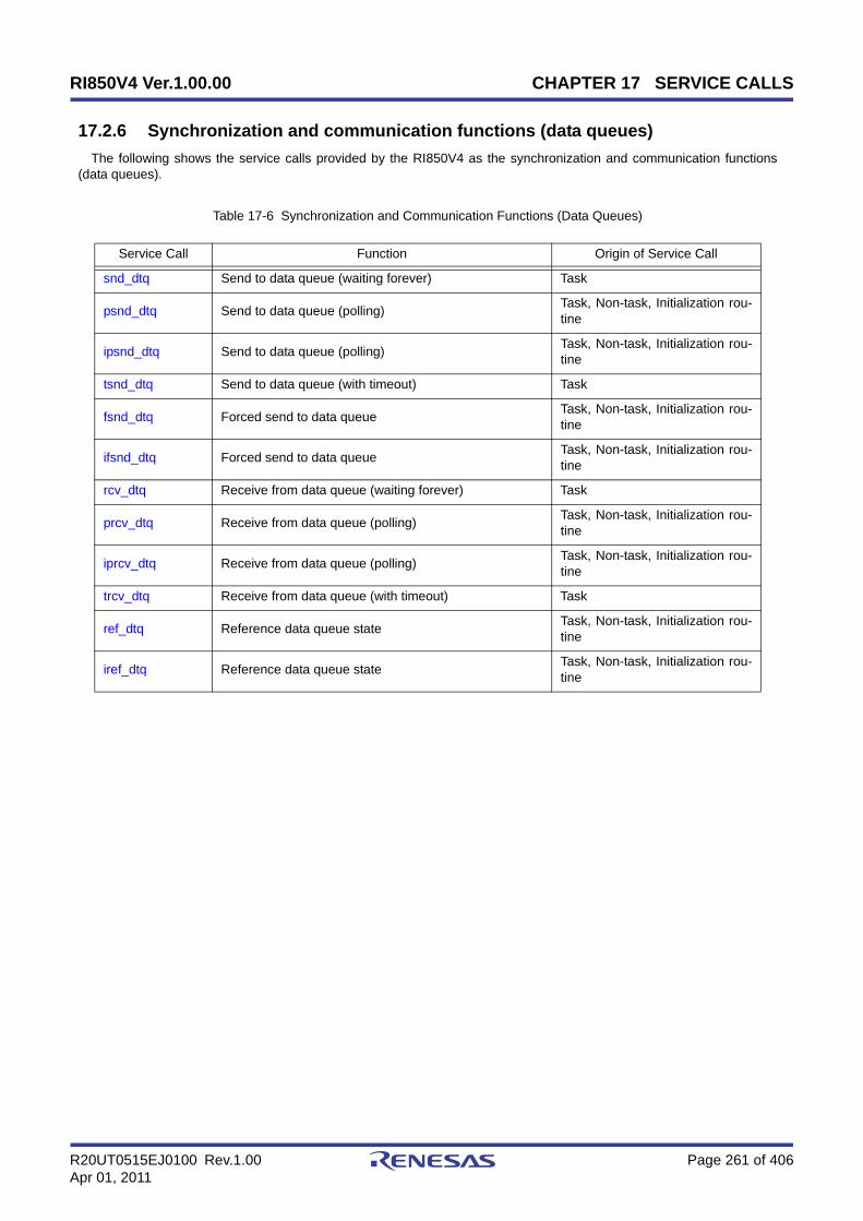
RI850V4 Ver.1.00.00 CHAPTER 17 SERVICE CALLS
R20UT0515EJ0100 Rev.1.00 Page 261 of 406Apr 01, 2011
17.2.6 Synchronization and communication functions (data queues)
The following shows the service calls provided by the RI850V4 as the synchronization and communication functions(data queues).
Table 17-6 Synchronization and Communication Functions (Data Queues)
Service Call Function Origin of Service Call
snd_dtq Send to data queue (waiting forever) Task
psnd_dtq Send to data queue (polling) Task, Non-task, Initialization rou-tine
ipsnd_dtq Send to data queue (polling) Task, Non-task, Initialization rou-tine
tsnd_dtq Send to data queue (with timeout) Task
fsnd_dtq Forced send to data queue Task, Non-task, Initialization rou-tine
ifsnd_dtq Forced send to data queue Task, Non-task, Initialization rou-tine
rcv_dtq Receive from data queue (waiting forever) Task
prcv_dtq Receive from data queue (polling) Task, Non-task, Initialization rou-tine
iprcv_dtq Receive from data queue (polling) Task, Non-task, Initialization rou-tine
trcv_dtq Receive from data queue (with timeout) Task
ref_dtq Reference data queue state Task, Non-task, Initialization rou-tine
iref_dtq Reference data queue state Task, Non-task, Initialization rou-tine

RI850V4 Ver.1.00.00 CHAPTER 17 SERVICE CALLS
R20UT0515EJ0100 Rev.1.00 Page 262 of 406Apr 01, 2011
snd_dtq
Outline
Send to data queue (waiting forever).
C format
ER snd_dtq (ID dtqid, VP_INT data);
Parameter(s)
Explanation
This service call writes data specified by parameter data to the data queue area of the data queue specified byparameter dtqid.
If there is no available space for writing data in the data queue area of the target data queue when this service call isissued, this service call does not write data but queues the invoking task to the transmission wait queue of the target dataqueue and moves it from the RUNNING state to the WAITING state (data transmission wait state).
The sending WAITING state for a data queue is cancelled in the following cases, and then moved to the READY state.
If a task has been queued to the reception wait queue of the target data queue when this service call is issued, thisservice call does not write data but transfers the data to the task. As a result, the task is unlinked from the reception waitqueue and moves from the WAITING state (data reception wait state) to the READY state, or from the WAITING-SUSPENDED state to the SUSPENDED state.
Note 1 Data is written to the data queue area of the target data queue in the order of the data transmission request.
Note 2 Invoking tasks are queued to the transmission wait queue of the target data queue in the order defined duringconfiguration (FIFO order or priority order).
I/O Parameter Description
I ID dtqid; ID number of the data queue to which the data element is sent.
I VP_INT data; Data element to be sent to the data queue.
Sending WAITING State for a Data Queue Cancel Operation Return Value
Available space was secured in the data queue area of the target data queue as a result ofissuing rcv_dtq. E_OK
Available space was secured in the data queue area of the target data queue as a result ofissuing prcv_dtq. E_OK
Available space was secured in the data queue area of the target data queue as a result ofissuing iprcv_dtq. E_OK
Available space was secured in the data queue area of the target data queue as a result ofissuing trcv_dtq. E_OK
Forced release from waiting (accept rel_wai while waiting). E_RLWAI
Forced release from waiting (accept irel_wai while waiting). E_RLWAI

RI850V4 Ver.1.00.00 CHAPTER 17 SERVICE CALLS
R20UT0515EJ0100 Rev.1.00 Page 263 of 406Apr 01, 2011
Return value
Macro Value Description
E_OK 0 Normal completion.
E_ID -18
Invalid ID number.
- dtqid < 0x0
- dtqid > Maximum ID number
E_CTX -25
Context error.
- This service call was issued from a non-task.
- This service call was issued in the CPU locked state.
- This service call was issued in the dispatching disabled state.
E_NOEXS -42Non-existent object.
- Specified data queue is not registered.
E_RLWAI -49Forced release from the WAITING state.
- Accept rel_wai/irel_wai while waiting.

RI850V4 Ver.1.00.00 CHAPTER 17 SERVICE CALLS
R20UT0515EJ0100 Rev.1.00 Page 264 of 406Apr 01, 2011
psnd_dtqipsnd_dtq
Outline
Send to data queue (polling).
C format
ER psnd_dtq (ID dtqid, VP_INT data);ER ipsnd_dtq (ID dtqid, VP_INT data);
Parameter(s)
Explanation
These service calls write data specified by parameter data to the data queue area of the data queue specified byparameter dtqid.
If there is no available space for writing data in the data queue area of the target data queue when either of theseservice calls is issued, data is not written but E_TMOUT is returned.
If a task has been queued to the reception wait queue of the target data queue when this service call is issued, thisservice call does not write data but transfers the data to the task. As a result, the task is unlinked from the reception waitqueue and moves from the WAITING state (data reception wait state) to the READY state, or from the WAITING-SUSPENDED state to the SUSPENDED state.
Note Data is written to the data queue area of the target data queue in the order of the data transmission request.
Return value
I/O Parameter Description
I ID dtqid; ID number of the data queue to which the data element is sent.
I VP_INT data; Data element to be sent to the data queue.
Macro Value Description
E_OK 0 Normal completion.
E_ID -18
Invalid ID number.
- dtqid < 0x0
- dtqid > Maximum ID number
E_CTX -25Context error.
- This service call was issued in the CPU locked state.
E_NOEXS -42Non-existent object.
- Specified data queue is not registered.
E_TMOUT -50Polling failure.
- There is no space in the target data queue.
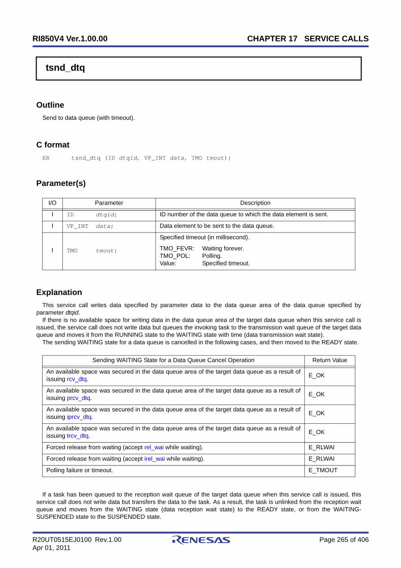
RI850V4 Ver.1.00.00 CHAPTER 17 SERVICE CALLS
R20UT0515EJ0100 Rev.1.00 Page 265 of 406Apr 01, 2011
tsnd_dtq
Outline
Send to data queue (with timeout).
C format
ER tsnd_dtq (ID dtqid, VP_INT data, TMO tmout);
Parameter(s)
Explanation
This service call writes data specified by parameter data to the data queue area of the data queue specified byparameter dtqid.
If there is no available space for writing data in the data queue area of the target data queue when this service call isissued, the service call does not write data but queues the invoking task to the transmission wait queue of the target dataqueue and moves it from the RUNNING state to the WAITING state with time (data transmission wait state).
The sending WAITING state for a data queue is cancelled in the following cases, and then moved to the READY state.
If a task has been queued to the reception wait queue of the target data queue when this service call is issued, thisservice call does not write data but transfers the data to the task. As a result, the task is unlinked from the reception waitqueue and moves from the WAITING state (data reception wait state) to the READY state, or from the WAITING-SUSPENDED state to the SUSPENDED state.
I/O Parameter Description
I ID dtqid; ID number of the data queue to which the data element is sent.
I VP_INT data; Data element to be sent to the data queue.
I TMO tmout;
Specified timeout (in millisecond).
TMO_FEVR: Waiting forever.TMO_POL: Polling.Value: Specified timeout.
Sending WAITING State for a Data Queue Cancel Operation Return Value
An available space was secured in the data queue area of the target data queue as a result ofissuing rcv_dtq. E_OK
An available space was secured in the data queue area of the target data queue as a result ofissuing prcv_dtq. E_OK
An available space was secured in the data queue area of the target data queue as a result ofissuing iprcv_dtq. E_OK
An available space was secured in the data queue area of the target data queue as a result ofissuing trcv_dtq. E_OK
Forced release from waiting (accept rel_wai while waiting). E_RLWAI
Forced release from waiting (accept irel_wai while waiting). E_RLWAI
Polling failure or timeout. E_TMOUT

RI850V4 Ver.1.00.00 CHAPTER 17 SERVICE CALLS
R20UT0515EJ0100 Rev.1.00 Page 266 of 406Apr 01, 2011
Note 1 Data is written to the data queue area of the target data queue in the order of the data transmission request.
Note 2 Invoking tasks are queued to the transmission wait queue of the target data queue in the order defined duringconfiguration (FIFO order or priority order).
Note 3 TMO_FEVR is specified for wait time tmout, processing equivalent to snd_dtq will be executed. WhenTMO_POL is specified, processing equivalent to psnd_dtq /ipsnd_dtq will be executed.
Return value
Macro Value Description
E_OK 0 Normal completion.
E_PAR -17Parameter error.
- tmout < TMO_FEVR
E_ID -18
Invalid ID number.
- dtqid < 0x0
- dtqid > Maximum ID number
E_CTX -25
Context error.
- This service call was issued from a non-task.
- This service call was issued in the CPU locked state.
- This service call was issued in the dispatching disabled state.
E_NOEXS -42Non-existent object.
- Specified data queue is not registered.
E_RLWAI -49Forced release from the WAITING state.
- Accept rel_wai/irel_wai while waiting.
E_TMOUT -50Timeout.
- Polling failure or timeout.

RI850V4 Ver.1.00.00 CHAPTER 17 SERVICE CALLS
R20UT0515EJ0100 Rev.1.00 Page 267 of 406Apr 01, 2011
fsnd_dtqifsnd_dtq
Outline
Forced send to data queue.
C format
ER fsnd_dtq (ID dtqid, VP_INT data);ER ifsnd_dtq (ID dtqid, VP_INT data);
Parameter(s)
Explanation
These service calls write data specified by parameter data to the data queue area of the data queue specified byparameter dtqid.
If there is no available space for writing data in the data queue area of the target data queue when either of theseservice calls is issued, the service call overwrites data to the area with the oldest data that was written.
If a task has been queued to the reception wait queue of the target data queue when this service call is issued, thisservice call does not write data but transfers the data to the task. As a result, the task is unlinked from the reception waitqueue and moves from the WAITING state (data reception wait state) to the READY state, or from the WAITING-SUSPENDED state to the SUSPENDED state.
Return value
I/O Parameter Description
I ID dtqid; ID number of the data queue to which the data element is sent.
I VP_INT data; Data element to be sent to the data queue.
Macro Value Description
E_OK 0 Normal completion.
E_ID -18
Invalid ID number.
- dtqid < 0x0
- dtqid > Maximum ID number
E_CTX -25Context error.
- This service call was issued in the CPU locked state.
E_ILUSE -28Illegal service call use.
- The capacity of the data queue area is 0.
E_NOEXS -42Non-existent object.
- Specified data queue is not registered.
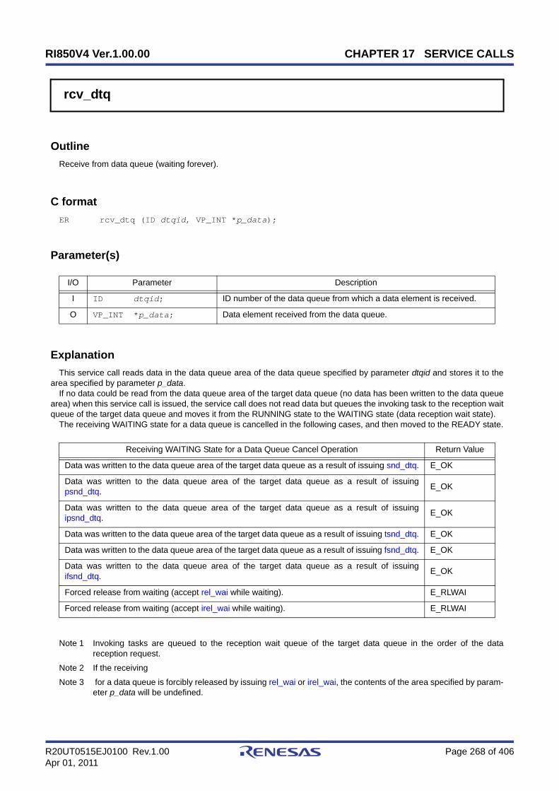
RI850V4 Ver.1.00.00 CHAPTER 17 SERVICE CALLS
R20UT0515EJ0100 Rev.1.00 Page 268 of 406Apr 01, 2011
rcv_dtq
Outline
Receive from data queue (waiting forever).
C format
ER rcv_dtq (ID dtqid, VP_INT *p_data);
Parameter(s)
Explanation
This service call reads data in the data queue area of the data queue specified by parameter dtqid and stores it to thearea specified by parameter p_data.
If no data could be read from the data queue area of the target data queue (no data has been written to the data queuearea) when this service call is issued, the service call does not read data but queues the invoking task to the reception waitqueue of the target data queue and moves it from the RUNNING state to the WAITING state (data reception wait state).
The receiving WAITING state for a data queue is cancelled in the following cases, and then moved to the READY state.
Note 1 Invoking tasks are queued to the reception wait queue of the target data queue in the order of the datareception request.
Note 2 If the receiving
Note 3 for a data queue is forcibly released by issuing rel_wai or irel_wai, the contents of the area specified by param-eter p_data will be undefined.
I/O Parameter Description
I ID dtqid; ID number of the data queue from which a data element is received.
O VP_INT *p_data; Data element received from the data queue.
Receiving WAITING State for a Data Queue Cancel Operation Return Value
Data was written to the data queue area of the target data queue as a result of issuing snd_dtq. E_OK
Data was written to the data queue area of the target data queue as a result of issuingpsnd_dtq. E_OK
Data was written to the data queue area of the target data queue as a result of issuingipsnd_dtq. E_OK
Data was written to the data queue area of the target data queue as a result of issuing tsnd_dtq. E_OK
Data was written to the data queue area of the target data queue as a result of issuing fsnd_dtq. E_OK
Data was written to the data queue area of the target data queue as a result of issuingifsnd_dtq. E_OK
Forced release from waiting (accept rel_wai while waiting). E_RLWAI
Forced release from waiting (accept irel_wai while waiting). E_RLWAI

RI850V4 Ver.1.00.00 CHAPTER 17 SERVICE CALLS
R20UT0515EJ0100 Rev.1.00 Page 269 of 406Apr 01, 2011
Return value
Macro Value Description
E_OK 0 Normal completion.
E_ID -18
Invalid ID number.
- dtqid < 0x0
- dtqid > Maximum ID number
E_CTX -25
Context error.
- This service call was issued from a non-task.
- This service call was issued in the CPU locked state.
- This service call was issued in the dispatching disabled state.
E_NOEXS -42Non-existent object.
- Specified data queue is not registered.
E_RLWAI -49Forced release from the WAITING state.
- Accept rel_wai/irel_wai while waiting.

RI850V4 Ver.1.00.00 CHAPTER 17 SERVICE CALLS
R20UT0515EJ0100 Rev.1.00 Page 270 of 406Apr 01, 2011
prcv_dtqiprcv_dtq
Outline
Receive from data queue (polling).
C format
ER prcv_dtq (ID dtqid, VP_INT *p_data);ER iprcv_dtq (ID dtqid, VP_INT *p_data);
Parameter(s)
Explanation(s)
These service calls read data in the data queue area of the data queue specified by parameter dtqid and stores it to thearea specified by parameter p_data.
If no data could be read from the data queue area of the target data queue (no data has been written to the data queuearea) when either of these service calls is issued, the service call does not read data but E_TMOUT is returned.
Note If no data could be read from the data queue area of the target data queue (no data has been written to thedata queue area) when either of these service calls is issued, the contents in the area specified by parameterp_data become undefined.
Return value
I/O Parameter Description
I ID dtqid; ID number of the data queue from which a data element is received.
O VP_INT *p_data; Data element received from the data queue.
Macro Value Description
E_OK 0 Normal completion.
E_ID -18
Invalid ID number.
- dtqid < 0x0
- dtqid > Maximum ID number
E_CTX -25Context error.
- This service call was issued in the CPU locked state.
E_NOEXS -42Non-existent object.
- Specified data queue is not registered.
E_TMOUT -50Polling failure.
- No data exists in the target data queue.

RI850V4 Ver.1.00.00 CHAPTER 17 SERVICE CALLS
R20UT0515EJ0100 Rev.1.00 Page 271 of 406Apr 01, 2011
trcv_dtq
Outline
Receive from data queue (with timeout).
C format
ER trcv_dtq (ID dtqid, VP_INT *p_data, TMO tmout);
Parameter(s)
Explanation
This service call reads data in the data queue area of the data queue specified by parameter dtqid and stores it to thearea specified by parameter p_data.
If no data could be read from the data queue area of the target data queue (no data has been written to the data queuearea) when this service call is issued, the service call does not read data but queues the invoking task to the reception waitqueue of the target data queue and moves it from the RUNNING state to the WAITING state with time out (data receptionwait state).
The receiving WAITING state for a data queue is cancelled in the following cases, and then moved to the READY state.
I/O Parameter Description
I ID dtqid; ID number of the data queue from which a data element is received.
O VP_INT *p_data; Data element received from the data queue.
I TMO tmout;
Specified timeout (in millisecond).
TMO_FEVR: Waiting forever.TMO_POL: Polling.Value: Specified timeout.
Receiving WAITING State for a Data Queue Cancel Operation Return Value
Data was written to the data queue area of the target data queue as a result of issuing snd_dtq. E_OK
Data was written to the data queue area of the target data queue as a result of issuingpsnd_dtq. E_OK
Data was written to the data queue area of the target data queue as a result of issuingipsnd_dtq. E_OK
Data was written to the data queue area of the target data queue as a result of issuing tsnd_dtq. E_OK
Data was written to the data queue area of the target data queue as a result of issuing fsnd_dtq. E_OK
Data was written to the data queue area of the target data queue as a result of issuingifsnd_dtq. E_OK
Forced release from waiting (accept rel_wai while waiting). E_RLWAI
Forced release from waiting (accept irel_wai while waiting). E_RLWAI
Polling failure or timeout. E_TMOUT

RI850V4 Ver.1.00.00 CHAPTER 17 SERVICE CALLS
R20UT0515EJ0100 Rev.1.00 Page 272 of 406Apr 01, 2011
Note 1 Invoking tasks are queued to the reception wait queue of the target data queue in the order of the datareception request.
Note 2 If the data reception wait state is cancelled because rel_wai or irel_wai was issued or the wait time elapsed,the contents in the area specified by parameter p_data become undefined.
Note 3 TMO_FEVR is specified for wait time tmout, processing equivalent to rcv_dtq will be executed. WhenTMO_POL is specified, processing equivalent to prcv_dtq /iprcv_dtq will be executed.
Return value
Macro Value Description
E_OK 0 Normal completion.
E_PAR -17Parameter error.
- tmout < TMO_FEVR
E_ID -18
Invalid ID number.
- dtqid < 0x0
- dtqid > Maximum ID number
E_CTX -25
Context error.
- This service call was issued from a non-task.
- This service call was issued in the CPU locked state.
- This service call was issued in the dispatching disabled state.
E_NOEXS -42Non-existent object.
- Specified data queue is not registered.
E_RLWAI -49Forced release from the WAITING state.
- Accept rel_wai/irel_wai while waiting.
E_TMOUT -50Timeout.
- Polling failure or timeout.

RI850V4 Ver.1.00.00 CHAPTER 17 SERVICE CALLS
R20UT0515EJ0100 Rev.1.00 Page 273 of 406Apr 01, 2011
ref_dtqiref_dtq
Outline
Reference data queue state.
C format
ER ref_dtq (ID dtqid, T_RDTQ *pk_rdtq);ER iref_dtq (ID dtqid, T_RDTQ *pk_rdtq);
Parameter(s)
[Data queue state packet: T_RDTQ]
Explanation
These service calls store the detailed information of the data queue (existence of waiting tasks, number of dataelements in the data queue, etc.) specified by parameter dtqid into the area specified by parameter pk_rdtq.
Note For details about the data queue state packet, refer to "16.2.6 Data queue state packet".
Return value
I/O Parameter Description
I ID dtqid; ID number of the data queue to be referenced.
O T_RDTQ *pk_rdtq; Pointer to the packet returning the data queue state.
typedef struct t_rdtq { ID stskid; /*Existence of tasks waiting for data transmission*/ ID rtskid; /*Existence of tasks waiting for data reception*/ UINT sdtqcnt; /*Number of data elements in data queue*/ ATR dtqatr; /*Attribute*/ UINT dtqcnt; /*Data count*/ ID memid; /*Reserved for future use*/} T_RDTQ;
Macro Value Description
E_OK 0 Normal completion.
E_ID -18
Invalid ID number.
- dtqid < 0x0
- dtqid > Maximum ID number
E_CTX -25Context error.
- This service call was issued in the CPU locked state.
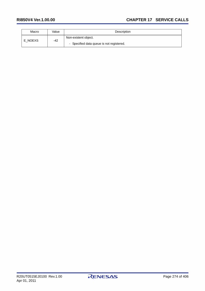
RI850V4 Ver.1.00.00 CHAPTER 17 SERVICE CALLS
R20UT0515EJ0100 Rev.1.00 Page 274 of 406Apr 01, 2011
E_NOEXS -42Non-existent object.
- Specified data queue is not registered.
Macro Value Description

RI850V4 Ver.1.00.00 CHAPTER 17 SERVICE CALLS
R20UT0515EJ0100 Rev.1.00 Page 275 of 406Apr 01, 2011
17.2.7 Synchronization and communication functions (mailboxes)
The following shows the service calls provided by the RI850V4 as the syncronization and communication functions(mailboxes).
Table 17-7 Synchronization and Communication Functions (Mailboxes)
Service Call Function Origin of Service Call
snd_mbx Send to mailbox Task, Non-task, Initialization rou-tine
isnd_mbx Send to mailbox Task, Non-task, Initialization rou-tine
rcv_mbx Receive from mailbox (waiting forever) Task
prcv_mbx Receive from mailbox (polling) Task, Non-task, Initialization rou-tine
iprcv_mbx Receive from mailbox (polling) Task, Non-task, Initialization rou-tine
trcv_mbx Receive from mailbox (with timeout) Task
ref_mbx Reference mailbox state Task, Non-task, Initialization rou-tine
iref_mbx Reference mailbox state Task, Non-task, Initialization rou-tine
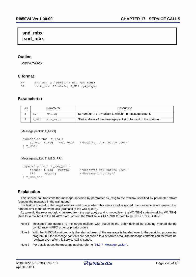
RI850V4 Ver.1.00.00 CHAPTER 17 SERVICE CALLS
R20UT0515EJ0100 Rev.1.00 Page 276 of 406Apr 01, 2011
snd_mbxisnd_mbx
Outline
Send to mailbox.
C format
ER snd_mbx (ID mbxid, T_MSG *pk_msg);ER isnd_mbx (ID mbxid, T_MSG *pk_msg);
Parameter(s)
[Message packet: T_MSG]
[Message packet: T_MSG_PRI]
Explanation
This service call transmits the message specified by parameter pk_msg to the mailbox specified by parameter mbxid(queues the message in the wait queue).
If a task is queued to the target mailbox wait queue when this service call is issued, the message is not queued buthanded over to the relevant task (first task of the wait queue).
As a result, the relevant task is unlinked from the wait queue and is moved from the WAITING state (receiving WAITINGstate for a mailbox) to the READY state, or from the WAITING-SUSPENDED state to the SUSPENDED state.
Note 1 Messages are queued to the target mailbox wait queue in the order defined by queuing method duringconfiguration (FIFO order or priority order).
Note 2 With the RI850V4 mailbox, only the start address of the message is handed over to the receiving processingprogram, but the message contents are not copied to a separate area. The message contents can therefore berewritten even after this service call is issued.
Note 3 For details about the message packet, refer to "16.2.7 Message packet".
I/O Parameter Description
I ID mbxid; ID number of the mailbox to which the message is sent.
I T_MSG *pk_msg; Start address of the message packet to be sent to the mailbox.
typedef struct t_msg { struct t_msg *msgnext; /*Reserved for future use*/} T_MSG;
typedef struct t_msg_pri { struct t_msg msgque; /*Reserved for future use*/ PRI msgpri; /*Message priority*/} T_MSG_PRI;
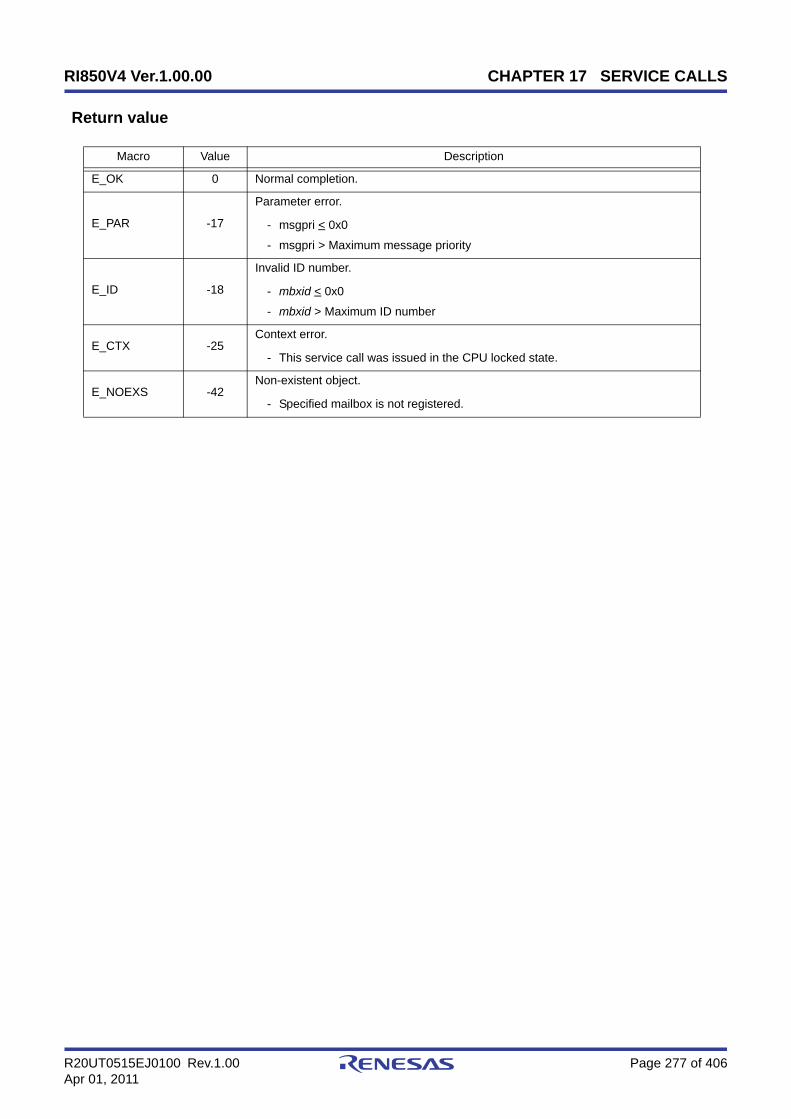
RI850V4 Ver.1.00.00 CHAPTER 17 SERVICE CALLS
R20UT0515EJ0100 Rev.1.00 Page 277 of 406Apr 01, 2011
Return value
Macro Value Description
E_OK 0 Normal completion.
E_PAR -17
Parameter error.
- msgpri < 0x0
- msgpri > Maximum message priority
E_ID -18
Invalid ID number.
- mbxid < 0x0
- mbxid > Maximum ID number
E_CTX -25Context error.
- This service call was issued in the CPU locked state.
E_NOEXS -42Non-existent object.
- Specified mailbox is not registered.

RI850V4 Ver.1.00.00 CHAPTER 17 SERVICE CALLS
R20UT0515EJ0100 Rev.1.00 Page 278 of 406Apr 01, 2011
rcv_mbx
Outline
Receive from mailbox (waiting forever).
C format
ER rcv_mbx (ID mbxid, T_MSG **ppk_msg);
Parameter(s)
[Message packet: T_MSG]
[Message packet: T_MSG_PRI]
Explanation
This service call receives a message from the mailbox specified by parameter mbxid, and stores its start address in thearea specified by parameter ppk_msg.
If no message could be received from the target mailbox (no messages were queued to the wait queue) when thisservice call is issued, this service call does not receive messages but queues the invoking task to the target mailbox waitqueue and moves it from the RUNNING state to the WAITING state (message reception wait state).
The receiving WAITING state for a mailbox is cancelled in the following cases, and then moved to the READY state.
Note 1 Invoking tasks are queued to the target mailbox wait queue in the order defined during configuration (FIFOorder or priority order).
I/O Parameter Description
I ID mbxid; ID number of the mailbox from which a message is received.
O T_MSG **ppk_msg; Start address of the message packet received from the mailbox.
typedef struct t_msg { struct t_msg *msgnext; /*Reserved for future use*/} T_MSG;
typedef struct t_msg_pri { struct t_msg msgque; /*Reserved for future use*/ PRI msgpri; /*Message priority*/} T_MSG_PRI;
Receiving WAITING State for a Mailbox Cancel Operation Return Value
A message was transmitted to the target mailbox as a result of issuing snd_mbx. E_OK
A message was transmitted to the target mailbox as a result of issuing isnd_mbx. E_OK
Forced release from waiting (accept rel_wai while waiting). E_RLWAI
Forced release from waiting (accept irel_wai while waiting). E_RLWAI
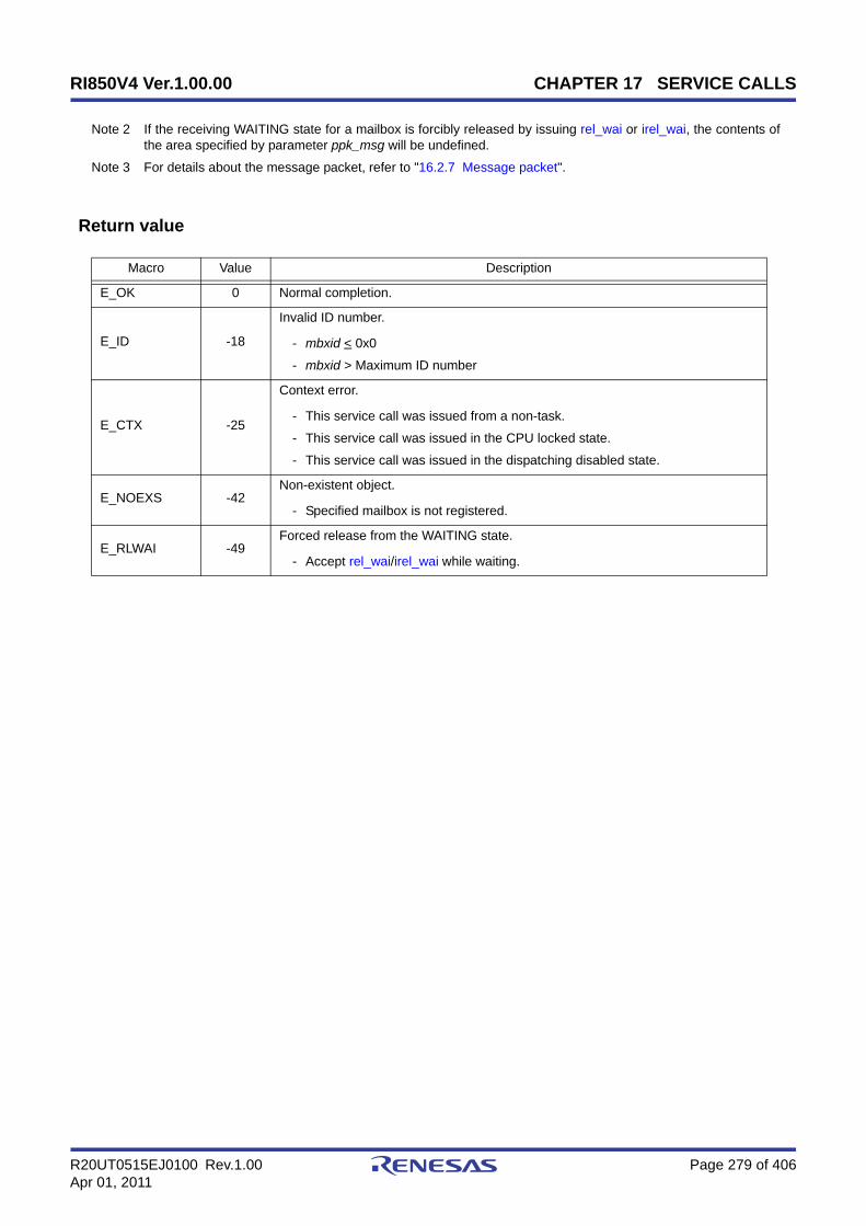
RI850V4 Ver.1.00.00 CHAPTER 17 SERVICE CALLS
R20UT0515EJ0100 Rev.1.00 Page 279 of 406Apr 01, 2011
Note 2 If the receiving WAITING state for a mailbox is forcibly released by issuing rel_wai or irel_wai, the contents ofthe area specified by parameter ppk_msg will be undefined.
Note 3 For details about the message packet, refer to "16.2.7 Message packet".
Return value
Macro Value Description
E_OK 0 Normal completion.
E_ID -18
Invalid ID number.
- mbxid < 0x0
- mbxid > Maximum ID number
E_CTX -25
Context error.
- This service call was issued from a non-task.
- This service call was issued in the CPU locked state.
- This service call was issued in the dispatching disabled state.
E_NOEXS -42Non-existent object.
- Specified mailbox is not registered.
E_RLWAI -49Forced release from the WAITING state.
- Accept rel_wai/irel_wai while waiting.

RI850V4 Ver.1.00.00 CHAPTER 17 SERVICE CALLS
R20UT0515EJ0100 Rev.1.00 Page 280 of 406Apr 01, 2011
prcv_mbxiprcv_mbx
Outline
Receive from mailbox (polling).
C format
ER prcv_mbx (ID mbxid, T_MSG **ppk_msg);ER iprcv_mbx (ID mbxid, T_MSG **ppk_msg);
Parameter(s)
[Message packet: T_MSG]
[Message packet: T_MSG_PRI]
Explanation
This service call receives a message from the mailbox specified by parameter mbxid, and stores its start address in thearea specified by parameter ppk_msg.
If the message could not be received from the target mailbox (no messages were queued in the wait queue) when thisservice call is issued, message reception processing is not executed but "E_TMOUT" is returned.
Note 1 If no message could be received from the target mailbox (no messages were queued to the wait queue) whenthis service call is issued, the contents in the area specified by parameter ppk_msg become undefined.
Note 2 For details about the message packet, refer to "16.2.7 Message packet".
Return value
I/O Parameter Description
I ID mbxid; ID number of the mailbox from which a message is received.
O T_MSG **ppk_msg; Start address of the message packet received from the mailbox.
typedef struct t_msg { struct t_msg *msgnext; /*Reserved for future use*/} T_MSG;
typedef struct t_msg_pri { struct t_msg msgque; /*Reserved for future use*/ PRI msgpri; /*Message priority*/} T_MSG_PRI;
Macro Value Description
E_OK 0 Normal completion.

RI850V4 Ver.1.00.00 CHAPTER 17 SERVICE CALLS
R20UT0515EJ0100 Rev.1.00 Page 281 of 406Apr 01, 2011
E_ID -18
Invalid ID number.
- mbxid < 0x0
- mbxid > Maximum ID number
E_CTX -25Context error.
- This service call was issued in the CPU locked state.
E_NOEXS -42Non-existent object.
- Specified mailbox is not registered.
E_TMOUT -50Polling failure.
- No message exists in the target mailbox.
Macro Value Description

RI850V4 Ver.1.00.00 CHAPTER 17 SERVICE CALLS
R20UT0515EJ0100 Rev.1.00 Page 282 of 406Apr 01, 2011
trcv_mbx
Outline
Receive from mailbox (with timeout).
C format
ER trcv_mbx (ID mbxid, T_MSG **ppk_msg, TMO tmout);
Parameter(s)
[Message packet: T_MSG]
[Message packet: T_MSG_PRI]
Explanation
This service call receives a message from the mailbox specified by parameter mbxid, and stores its start address in thearea specified by parameter ppk_msg.
If no message could be received from the target mailbox (no messages were queued to the wait queue) when thisservice call is issued, this service call does not receive messages but queues the invoking task to the target mailbox waitqueue and moves it from the RUNNING state to the WAITING state with timeout (message reception wait state).
The receiving WAITING state for a mailbox is cancelled in the following cases, and then moved to the READY state.
I/O Parameter Description
I ID mbxid; ID number of the mailbox from which a message is received.
O T_MSG **ppk_msg; Start address of the message packet received from the mailbox.
I TMO tmout;
Specified timeout (in millisecond).
TMO_FEVR: Waiting forever.TMO_POL: Polling.Value: Specified timeout.
typedef struct t_msg { struct t_msg *msgnext; /*Reserved for future use*/} T_MSG;
typedef struct t_msg_pri { struct t_msg msgque; /*Reserved for future use*/ PRI msgpri; /*Message priority*/} T_MSG_PRI;
Receiving WAITING State for a Mailbox Cancel Operation Return Value
A message was transmitted to the target mailbox as a result of issuing snd_mbx. E_OK
A message was transmitted to the target mailbox as a result of issuing isnd_mbx. E_OK
Forced release from waiting (accept rel_wai while waiting). E_RLWAI

RI850V4 Ver.1.00.00 CHAPTER 17 SERVICE CALLS
R20UT0515EJ0100 Rev.1.00 Page 283 of 406Apr 01, 2011
Note 1 Invoking tasks are queued to the target mailbox wait queue in the order defined during configuration (FIFOorder or priority order).
Note 2 If the message reception wait state is cancelled because rel_wai or irel_wai was issued or the wait timeelapsed, the contents in the area specified by parameter ppk_msg become undefined.
Note 3 TMO_FEVR is specified for wait time tmout, processing equivalent to rcv_mbx will be executed. WhenTMO_POL is specified, processing equivalent to prcv_mbx /iprcv_mbx will be executed.
Note 4 For details about the message packet, refer to "16.2.7 Message packet".
Return value
Forced release from waiting (accept irel_wai while waiting). E_RLWAI
Polling failure or timeout. E_TMOUT
Macro Value Description
E_OK 0 Normal completion.
E_PAR -17Parameter error.
- tmout < TMO_FEVR
E_ID -18
Invalid ID number.
- mbxid < 0x0
- mbxid > Maximum ID number
E_CTX -25
Context error.
- This service call was issued from a non-task.
- This service call was issued in the CPU locked state.
- This service call was issued in the dispatching disabled state.
E_NOEXS -42Non-existent object.
- Specified mailbox is not registered.
E_RLWAI -49Forced release from the WAITING state.
- Accept rel_wai/irel_wai while waiting.
E_TMOUT -50Timeout.
- Polling failure or timeout.
Receiving WAITING State for a Mailbox Cancel Operation Return Value

RI850V4 Ver.1.00.00 CHAPTER 17 SERVICE CALLS
R20UT0515EJ0100 Rev.1.00 Page 284 of 406Apr 01, 2011
ref_mbxiref_mbx
Outline
Reference mailbox state.
C format
ER ref_mbx (ID mbxid, T_RMBX *pk_rmbx);ER iref_mbx (ID mbxid, T_RMBX *pk_rmbx);
Parameter(s)
[Mailbox state packet: T_RMBX]
Explanation
Stores mailbox state packet (ID number of the task at the head of the wait queue, start address of the message packetat the head of the wait queue) of the mailbox specified by parameter mbxid in the area specified by parameter pk_rmbx.
Note For details about the mailbox state packet, refer to "16.2.8 Mailbox state packet".
Return value
I/O Parameter Description
I ID mbxid; ID number of the mailbox to be referenced.
O T_RMBX *pk_rmbx; Pointer to the packet returning the mailbox state.
typedef struct t_rmbx { ID wtskid; /*Existence of waiting task*/ T_MSG *pk_msg; /*Existence of waiting message*/ ATR mbxatr; /*Attribute*/} T_RMBX;
Macro Value Description
E_OK 0 Normal completion.
E_ID -18
Invalid ID number.
- mbxid < 0x0
- mbxid > Maximum ID number
E_CTX -25Context error.
- This service call was issued in the CPU locked state.
E_NOEXS -42Non-existent object.
- Specified mailbox is not registered.

RI850V4 Ver.1.00.00 CHAPTER 17 SERVICE CALLS
R20UT0515EJ0100 Rev.1.00 Page 285 of 406Apr 01, 2011
17.2.8 Extended synchronization and communication functions (mutexes)
The following shows the service calls provided by the RI850V4 as the extended synchronization and communicationfunctions (mutexes).
Table 17-8 Extended Synchronization and Communication Functions (Mutexes)
Service Call Function Origin of Service Call
loc_mtx Lock mutex (waiting forever) Task
ploc_mtx Lock mutex (polling) Task
tloc_mtx Lock mutex (with timeout) Task
unl_mtx Unlock mutex Task
ref_mtx Reference mutex state Task, Non-task, Initialization rou-tine
iref_mtx Reference mutex state Task, Non-task, Initialization rou-tine
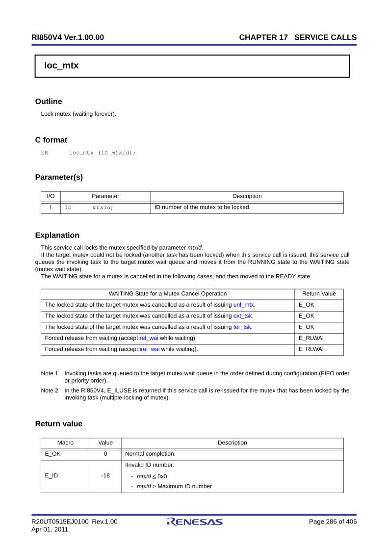
RI850V4 Ver.1.00.00 CHAPTER 17 SERVICE CALLS
R20UT0515EJ0100 Rev.1.00 Page 286 of 406Apr 01, 2011
loc_mtx
Outline
Lock mutex (waiting forever).
C format
ER loc_mtx (ID mtxid);
Parameter(s)
Explanation
This service call locks the mutex specified by parameter mtxid.If the target mutex could not be locked (another task has been locked) when this service call is issued, this service call
queues the invoking task to the target mutex wait queue and moves it from the RUNNING state to the WAITING state(mutex wait state).
The WAITING state for a mutex is cancelled in the following cases, and then moved to the READY state.
Note 1 Invoking tasks are queued to the target mutex wait queue in the order defined during configuration (FIFO orderor priority order).
Note 2 In the RI850V4, E_ILUSE is returned if this service call is re-issued for the mutex that has been locked by theinvoking task (multiple-locking of mutex).
Return value
I/O Parameter Description
I ID mtxid; ID number of the mutex to be locked.
WAITING State for a Mutex Cancel Operation Return Value
The locked state of the target mutex was cancelled as a result of issuing unl_mtx. E_OK
The locked state of the target mutex was cancelled as a result of issuing ext_tsk. E_OK
The locked state of the target mutex was cancelled as a result of issuing ter_tsk. E_OK
Forced release from waiting (accept rel_wai while waiting). E_RLWAI
Forced release from waiting (accept irel_wai while waiting). E_RLWAI
Macro Value Description
E_OK 0 Normal completion.
E_ID -18
IInvalid ID number.
- mtxid < 0x0
- mtxid > Maximum ID number
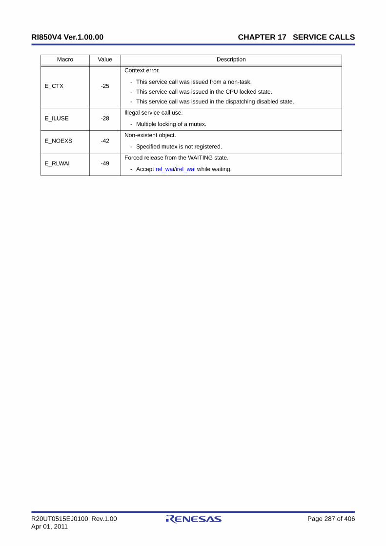
RI850V4 Ver.1.00.00 CHAPTER 17 SERVICE CALLS
R20UT0515EJ0100 Rev.1.00 Page 287 of 406Apr 01, 2011
E_CTX -25
Context error.
- This service call was issued from a non-task.
- This service call was issued in the CPU locked state.
- This service call was issued in the dispatching disabled state.
E_ILUSE -28Illegal service call use.
- Multiple locking of a mutex.
E_NOEXS -42Non-existent object.
- Specified mutex is not registered.
E_RLWAI -49Forced release from the WAITING state.
- Accept rel_wai/irel_wai while waiting.
Macro Value Description

RI850V4 Ver.1.00.00 CHAPTER 17 SERVICE CALLS
R20UT0515EJ0100 Rev.1.00 Page 288 of 406Apr 01, 2011
ploc_mtx
Outline
Lock mutex (polling).
C format
ER ploc_mtx (ID mtxid);
Parameter(s)
Explanation
This service call locks the mutex specified by parameter mtxid.If the target mutex could not be locked (another task has been locked) when this service call is issued but E_TMOUT is
returned.
Note In the RI850V4, E_ILUSE is returned if this service call is re-issued for the mutex that has been locked by theinvoking task (multiple-locking of mutex).
Return value
I/O Parameter Description
I ID mtxid; ID number of the mutex to be locked.
Macro Value Description
E_OK 0 Normal completion.
E_ID -18
Invalid ID number.
- mtxid < 0x0
- mtxid > Maximum ID number
E_CTX -25
Context error.
- This service call was issued from a non-task.
- This service call was issued in the CPU locked state.
E_ILUSE -28Illegal service call use.
- Multiple locking of a mutex.
E_NOEXS -42Non-existent object.
- Specified mutex is not registered.
E_TMOUT -50Polling failure.
- The target mutex has been locked by another task.

RI850V4 Ver.1.00.00 CHAPTER 17 SERVICE CALLS
R20UT0515EJ0100 Rev.1.00 Page 289 of 406Apr 01, 2011
tloc_mtx
Outline
Lock mutex (with timeout).
C format
ER tloc_mtx (ID mtxid, TMO tmout);
Parameter(s)
Explanation
This service call locks the mutex specified by parameter mtxid.If the target mutex could not be locked (another task has been locked) when this service call is issued, this service call
queues the invoking task to the target mutex wait queue and moves it from the RUNNING state to the WAITING state withtimeout (mutex wait state).
The WAITING state for a mutex is cancelled in the following cases, and then moved to the READY state.
Note 1 Invoking tasks are queued to the target mutex wait queue in the order defined during configuration (FIFO orderor priority order).
Note 2 In the RI850V4, E_ILUSE is returned if this service call is re-issued for the mutex that has been locked by theinvoking task (multiple-locking of mutex).
Note 3 TMO_FEVR is specified for wait time tmout, processing equivalent to loc_mtx will be executed. WhenTMO_POL is specified, processing equivalent to ploc_mtx will be executed.
I/O Parameter Description
I ID mtxid; ID number of the mutex to be locked.
I TMO tmout;
Specified timeout (in millisecond).
TMO_FEVR: Waiting forever.TMO_POL: Polling.Value: Specified timeout.
WAITING State for a Mutex Cancel Operation Return Value
The locked state of the target mutex was cancelled as a result of issuing unl_mtx. E_OK
The locked state of the target mutex was cancelled as a result of issuing ext_tsk. E_OK
The locked state of the target mutex was cancelled as a result of issuing ter_tsk. E_OK
Forced release from waiting (accept rel_wai while waiting). E_RLWAI
Forced release from waiting (accept irel_wai while waiting). E_RLWAI
Polling failure or timeout. E_TMOUT

RI850V4 Ver.1.00.00 CHAPTER 17 SERVICE CALLS
R20UT0515EJ0100 Rev.1.00 Page 290 of 406Apr 01, 2011
Return value
Macro Value Description
E_OK 0 Normal completion.
E_PAR -17Parameter error.
- tmout < TMO_FEVR
E_ID -18
Invalid ID number.
- mtxid < 0x0
- mtxid > Maximum ID number
E_CTX -25
Context error.
- This service call was issued from a non-task.
- This service call was issued in the CPU locked state.
- This service call was issued in the dispatching disabled state.
E_ILUSE -28Illegal service call use.
- Multiple locking of a mutex.
E_NOEXS -42Non-existent object.
- Specified mutex is not registered.
E_RLWAI -49Forced release from the WAITING state.
- Accept rel_wai/irel_wai while waiting.
E_TMOUT -50Timeout.
- Polling failure or timeout.
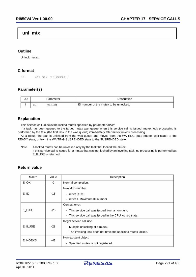
RI850V4 Ver.1.00.00 CHAPTER 17 SERVICE CALLS
R20UT0515EJ0100 Rev.1.00 Page 291 of 406Apr 01, 2011
unl_mtx
Outline
Unlock mutex.
C format
ER unl_mtx (ID mtxid);
Parameter(s)
Explanation
This service call unlocks the locked mutex specified by parameter mtxid.If a task has been queued to the target mutex wait queue when this service call is issued, mutex lock processing is
performed by the task (the first task in the wait queue) immediately after mutex unlock processing.As a result, the task is unlinked from the wait queue and moves from the WAITING state (mutex wait state) to the
READY state, or from the WAITING-SUSPENDED state to the SUSPENDED state.
Note A locked mutex can be unlocked only by the task that locked the mutex.If this service call is issued for a mutex that was not locked by an invoking task, no processing is performed butE_ILUSE is returned.
Return value
I/O Parameter Description
I ID mtxid; ID number of the mutex to be unlocked.
Macro Value Description
E_OK 0 Normal completion.
E_ID -18
Invalid ID number.
- mtxid < 0x0
- mtxid > Maximum ID number
E_CTX -25
Context error.
- This service call was issued from a non-task.
- This service call was issued in the CPU locked state.
E_ILUSE -28
Illegal service call use.
- Multiple unlocking of a mutex.
- The invoking task does not have the specified mutex locked.
E_NOEXS -42Non-existent object.
- Specified mutex is not registered.
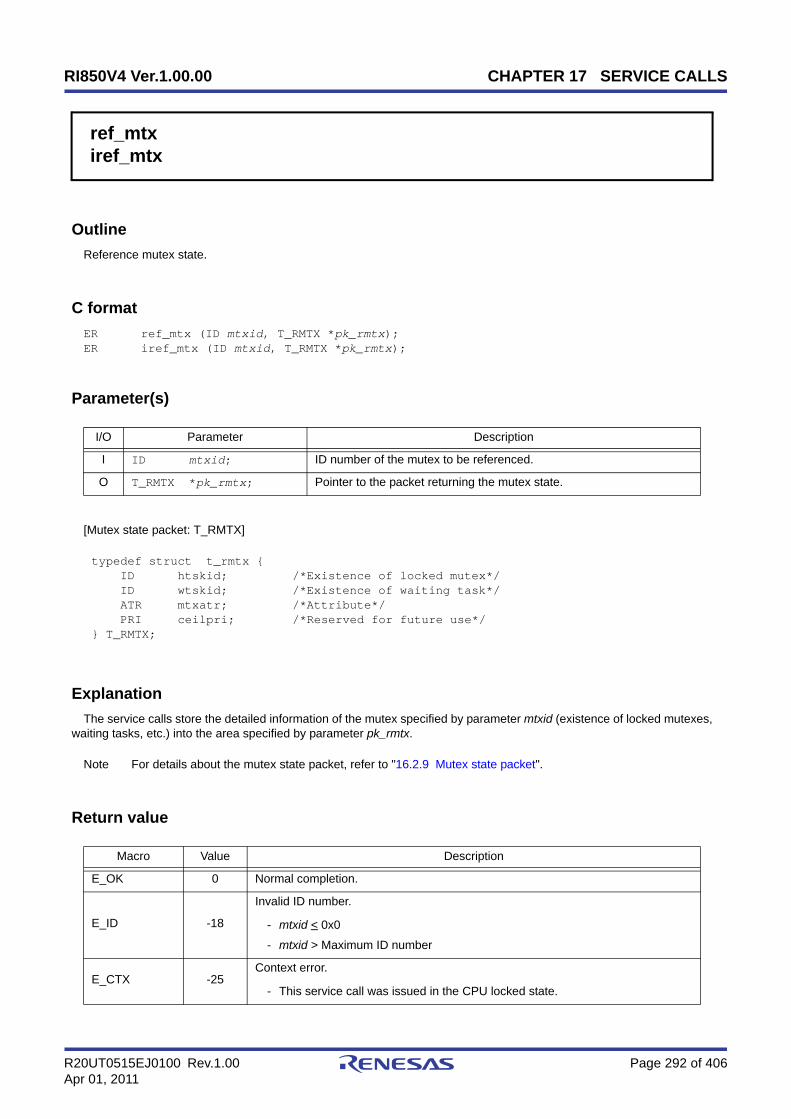
RI850V4 Ver.1.00.00 CHAPTER 17 SERVICE CALLS
R20UT0515EJ0100 Rev.1.00 Page 292 of 406Apr 01, 2011
ref_mtxiref_mtx
Outline
Reference mutex state.
C format
ER ref_mtx (ID mtxid, T_RMTX *pk_rmtx);ER iref_mtx (ID mtxid, T_RMTX *pk_rmtx);
Parameter(s)
[Mutex state packet: T_RMTX]
Explanation
The service calls store the detailed information of the mutex specified by parameter mtxid (existence of locked mutexes,waiting tasks, etc.) into the area specified by parameter pk_rmtx.
Note For details about the mutex state packet, refer to "16.2.9 Mutex state packet".
Return value
I/O Parameter Description
I ID mtxid; ID number of the mutex to be referenced.
O T_RMTX *pk_rmtx; Pointer to the packet returning the mutex state.
typedef struct t_rmtx { ID htskid; /*Existence of locked mutex*/ ID wtskid; /*Existence of waiting task*/ ATR mtxatr; /*Attribute*/ PRI ceilpri; /*Reserved for future use*/} T_RMTX;
Macro Value Description
E_OK 0 Normal completion.
E_ID -18
Invalid ID number.
- mtxid < 0x0
- mtxid > Maximum ID number
E_CTX -25Context error.
- This service call was issued in the CPU locked state.
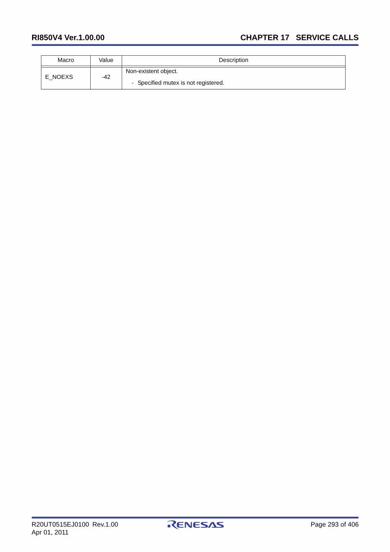
RI850V4 Ver.1.00.00 CHAPTER 17 SERVICE CALLS
R20UT0515EJ0100 Rev.1.00 Page 293 of 406Apr 01, 2011
E_NOEXS -42Non-existent object.
- Specified mutex is not registered.
Macro Value Description
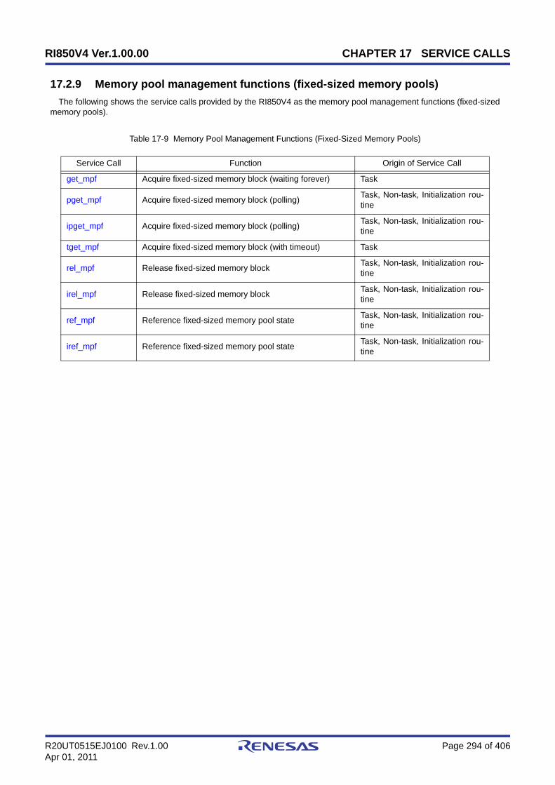
RI850V4 Ver.1.00.00 CHAPTER 17 SERVICE CALLS
R20UT0515EJ0100 Rev.1.00 Page 294 of 406Apr 01, 2011
17.2.9 Memory pool management functions (fixed-sized memory pools)
The following shows the service calls provided by the RI850V4 as the memory pool management functions (fixed-sizedmemory pools).
Table 17-9 Memory Pool Management Functions (Fixed-Sized Memory Pools)
Service Call Function Origin of Service Call
get_mpf Acquire fixed-sized memory block (waiting forever) Task
pget_mpf Acquire fixed-sized memory block (polling) Task, Non-task, Initialization rou-tine
ipget_mpf Acquire fixed-sized memory block (polling) Task, Non-task, Initialization rou-tine
tget_mpf Acquire fixed-sized memory block (with timeout) Task
rel_mpf Release fixed-sized memory block Task, Non-task, Initialization rou-tine
irel_mpf Release fixed-sized memory block Task, Non-task, Initialization rou-tine
ref_mpf Reference fixed-sized memory pool state Task, Non-task, Initialization rou-tine
iref_mpf Reference fixed-sized memory pool state Task, Non-task, Initialization rou-tine
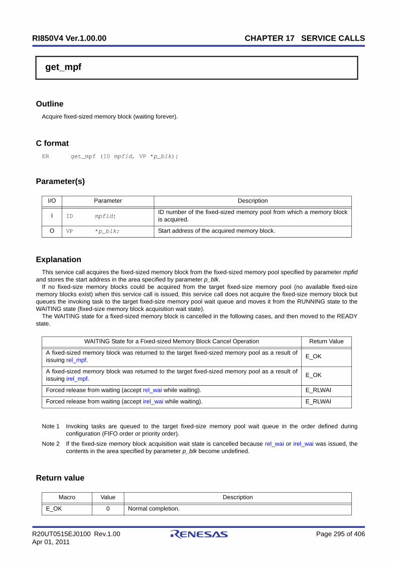
RI850V4 Ver.1.00.00 CHAPTER 17 SERVICE CALLS
R20UT0515EJ0100 Rev.1.00 Page 295 of 406Apr 01, 2011
get_mpf
Outline
Acquire fixed-sized memory block (waiting forever).
C format
ER get_mpf (ID mpfid, VP *p_blk);
Parameter(s)
Explanation
This service call acquires the fixed-sized memory block from the fixed-sized memory pool specified by parameter mpfidand stores the start address in the area specified by parameter p_blk.
If no fixed-size memory blocks could be acquired from the target fixed-size memory pool (no available fixed-sizememory blocks exist) when this service call is issued, this service call does not acquire the fixed-size memory block butqueues the invoking task to the target fixed-size memory pool wait queue and moves it from the RUNNING state to theWAITING state (fixed-size memory block acquisition wait state).
The WAITING state for a fixed-sized memory block is cancelled in the following cases, and then moved to the READYstate.
Note 1 Invoking tasks are queued to the target fixed-size memory pool wait queue in the order defined duringconfiguration (FIFO order or priority order).
Note 2 If the fixed-size memory block acquisition wait state is cancelled because rel_wai or irel_wai was issued, thecontents in the area specified by parameter p_blk become undefined.
Return value
I/O Parameter Description
I ID mpfid;ID number of the fixed-sized memory pool from which a memory blockis acquired.
O VP *p_blk; Start address of the acquired memory block.
WAITING State for a Fixed-sized Memory Block Cancel Operation Return Value
A fixed-sized memory block was returned to the target fixed-sized memory pool as a result ofissuing rel_mpf. E_OK
A fixed-sized memory block was returned to the target fixed-sized memory pool as a result ofissuing irel_mpf. E_OK
Forced release from waiting (accept rel_wai while waiting). E_RLWAI
Forced release from waiting (accept irel_wai while waiting). E_RLWAI
Macro Value Description
E_OK 0 Normal completion.

RI850V4 Ver.1.00.00 CHAPTER 17 SERVICE CALLS
R20UT0515EJ0100 Rev.1.00 Page 296 of 406Apr 01, 2011
E_ID -18
Invalid ID number.
- mpfid < 0x0
- mpfid > Maximum ID number
E_CTX -25
Context error.
- This service call was issued from a task.
- This service call was issued in the CPU locked state.
- This service call was issued in the dispatching disabled state.
E_NOEXS -42Non-existent object.
- Specified fixed-sized memory pool is not registered.
E_RLWAI -49Forced release from the WAITING state.
- Accept rel_wai/irel_wai while waiting.
Macro Value Description

RI850V4 Ver.1.00.00 CHAPTER 17 SERVICE CALLS
R20UT0515EJ0100 Rev.1.00 Page 297 of 406Apr 01, 2011
pget_mpfipget_mpf
Outline
Acquire fixed-sized memory block (polling).
C format
ER pget_mpf (ID mpfid, VP *p_blk);ER ipget_mpf (ID mpfid, VP *p_blk);
Parameter(s)
Explanation
This service call acquires the fixed-sized memory block from the fixed-sized memory pool specified by parameter mpfidand stores the start address in the area specified by parameter p_blk.
If a fixed-sized memory block could not be acquired from the target fixed-sized memory pool (no available fixed-sizedmemory blocks exist) when this service call is issued, fixed-sized memory block acquisition processing is not performedbut "E_TMOUT" is returned.
Note If no fixed-size memory blocks could be acquired from the target fixed-size memory pool (no available fixed-size memory blocks exist) when this service call is issued, the contents in the area specified by parameterp_blk become undefined.
Return value
I/O Parameter Description
I ID mpfid;ID number of the fixed-sized memory pool from which a memory blockis acquired.
O VP *p_blk; Start address of the acquired memory block.
Macro Value Description
E_OK 0 Normal completion.
E_ID -18
Invalid ID number.
- mpfid < 0x0
- mpfid > Maximum ID number
E_CTX -25Context error.
- This service call was issued in the CPU locked state.
E_NOEXS -42Non-existent object.
- Specified fixed-sized memory pool is not registered.
E_TMOUT -50Polling failure.
- There is no free memory block in the target fixed-sized memory pool.

RI850V4 Ver.1.00.00 CHAPTER 17 SERVICE CALLS
R20UT0515EJ0100 Rev.1.00 Page 298 of 406Apr 01, 2011
tget_mpf
Outline
Acquire fixed-sized memory block (with timeout).
C format
ER tget_mpf (ID mpfid, VP *p_blk, TMO tmout);
Parameter(s)
Explanation
This service call acquires the fixed-sized memory block from the fixed-sized memory pool specified by parameter mpfidand stores the start address in the area specified by parameter p_blk.
If no fixed-size memory blocks could be acquired from the target fixed-size memory pool (no available fixed-sizememory blocks exist) when this service call is issued, this service call does not acquire the fixed-size memory block butqueues the invoking task to the target fixed-size memory pool wait queue and moves it from the RUNNING state to theWAITING state with timeout (fixed-size memory block acquisition wait state).
The WAITING state for a fixed-sized memory block is cancelled in the following cases, and then moved to the READYstate.
Note 1 Invoking tasks are queued to the target fixed-size memory pool wait queue in the order defined duringconfiguration (FIFO order or priority order).
Note 2 If the fixed-size memory block acquisition wait state is cancelled because rel_wai or irel_wai was issued or thewait time elapsed, the contents in the area specified by parameter p_blk become undefined.
Note 3 TMO_FEVR is specified for wait time tmout, processing equivalent to get_mpf will be executed. WhenTMO_POL is specified, processing equivalent to pget_mpf /ipget_mpf will be executed.
I/O Parameter Description
I ID mpfid;ID number of the fixed-sized memory pool from which a memory blockis acquired.
O VP *p_blk; Start address of the acquired memory block.
I TMO tmout;
Specified timeout (in millisecond).
TMO_FEVR: Waiting forever.TMO_POL: Polling.Value: Specified timeout.
WAITING State for a Fixed-sized Memory Block Cancel Operation Return Value
A fixed-sized memory block was returned to the target fixed-sized memory pool as a result ofissuing rel_mpf. E_OK
A fixed-sized memory block was returned to the target fixed-sized memory pool as a result ofissuing irel_mpf. E_OK
Forced release from waiting (accept rel_wai while waiting). E_RLWAI
Forced release from waiting (accept irel_wai while waiting). E_RLWAI
Polling failure or timeout. E_TMOUT

RI850V4 Ver.1.00.00 CHAPTER 17 SERVICE CALLS
R20UT0515EJ0100 Rev.1.00 Page 299 of 406Apr 01, 2011
Return value
Macro Value Description
E_OK 0 Normal completion.
E_PAR -17Parameter error.
- tmout < TMO_FEVR
E_ID -18
Invalid ID number.
- mpfid < 0x0
- mpfid > Maximum ID number
E_CTX -25
Context error.
- This service call was issued from a non-task.
- This service call was issued in the CPU locked state.
- This service call was issued in the dispatching disabled state.
E_NOEXS -42Non-existent object.
- Specified fixed-sized memory pool is not registered.
E_RLWAI -49Forced release from the WAITING state.
- Accept rel_wai/irel_wai while waiting.
E_TMOUT -50Timeout.
- Polling failure or timeout.

RI850V4 Ver.1.00.00 CHAPTER 17 SERVICE CALLS
R20UT0515EJ0100 Rev.1.00 Page 300 of 406Apr 01, 2011
rel_mpfirel_mpf
Outline
Release fixed-sized memory block.
C format
ER rel_mpf (ID mpfid, VP blk);ER irel_mpf (ID mpfid, VP blk);
Parameter(s)
Explanation
This service call returns the fixed-sized memory block specified by parameter blk to the fixed-sized memory poolspecified by parameter mpfid.
If a task is queued to the target fixed-sized memory pool wait queue when this service call is issued, fixed-sized memoryblock return processing is not performed but fixed-sized memory blocks are returned to the relevant task (first task of waitqueue).
As a result, the relevant task is unlinked from the wait queue and is moved from the WAITING state (WAITING state fora fixed-sized memory block) to the READY state, or from the WAITING-SUSPENDED state to the SUSPENDED state.
Note 1 The RI850V4 does not perform memory clear processing when returning the acquired fixed-size memoryblock. The contents of the returned fixed-size memory block are therefore undefined.
Note 2 When returning fixed-size memory blocks, be sure to issue either of these service calls for the acquired fixed-size memory pools. If the service call is issued for another fixed-size memory pool, no error results but theoperation is not guaranteed after that.
Return value
I/O Parameter Description
I ID mpfid;ID number of the fixed-sized memory pool to which the memory block isreleased.
I VP blk; Start address of the memory block to be released.
Macro Value Description
E_OK 0 Normal completion.
E_ID -18
Invalid ID number.
- mpfid < 0x0
- mpfid > Maximum ID number
E_CTX -25Context error.
- This service call was issued in the CPU locked state.

RI850V4 Ver.1.00.00 CHAPTER 17 SERVICE CALLS
R20UT0515EJ0100 Rev.1.00 Page 301 of 406Apr 01, 2011
E_NOEXS -42Non-existent object.
- Specified fixed-sized memory pool is not registered.
Macro Value Description

RI850V4 Ver.1.00.00 CHAPTER 17 SERVICE CALLS
R20UT0515EJ0100 Rev.1.00 Page 302 of 406Apr 01, 2011
ref_mpfiref_mpf
Outline
Reference fixed-sized memory pool state.
C format
ER ref_mpf (ID mpfid, T_RMPF *pk_rmpf);ER iref_mpf (ID mpfid, T_RMPF *pk_rmpf);
Parameter(s)
[Fixed-sized memory pool state packet: T_RMPF]
Explanation
Stores fixed-sized memory pool state packet (ID number of the task at the head of the wait queue, number of free mem-ory blocks, etc.) of the fixed-sized memory pool specified by parameter mpfid in the area specified by parameter pk_rmpf.
Note For details about the fixed-sized memory pool state packet, refer to "16.2.10 Fixed-sized memory pool statepacket".
Return value
I/O Parameter Description
I ID mpfid; ID number of the fixed-sized memory pool to be referenced.
O T_RMPF *pk_rmpf; Pointer to the packet returning the fixed-sized memory pool state.
typedef struct t_rmpf { ID wtskid; /*Existence of waiting task*/ UINT fblkcnt; /*Number of free memory blocks*/ ATR mpfatr; /*Attribute*/ ID memid; /*Reserved for future use*/} T_RMPF;
Macro Value Description
E_OK 0 Normal completion.
E_ID -18
Invalid ID number.
- mpfid < 0x0
- mpfid > Maximum ID number
E_CTX -25Context error.
- This service call was issued in the CPU locked state.
RI850V4 Ver.1.00.00 CHAPTER 17 SERVICE CALLS
R20UT0515EJ0100 Rev.1.00 Page 303 of 406Apr 01, 2011
E_NOEXS -42Non-existent object.
- Specified fixed-sized memory pool is not registered.
Macro Value Description

RI850V4 Ver.1.00.00 CHAPTER 17 SERVICE CALLS
R20UT0515EJ0100 Rev.1.00 Page 304 of 406Apr 01, 2011
17.2.10 Memory pool management functions (variable-sized memory pools)
The following shows the service calls provided by the RI850V4 as the memory pool management functions (variable-sized memory pools).
Table 17-10 Memory Pool Management Functions (Variable-Sized Memory Pools)
Service Call Function Origin of Service Call
get_mpl Acquire variable-sized memory block (waiting forever) Task
pget_mpl Acquire variable-sized memory block (polling) Task, Non-task, Initialization rou-tine
ipget_mpl Acquire variable-sized memory block (polling) Task, Non-task, Initialization rou-tine
tget_mpl Acquire variable-sized memory block (with timeout) Task
rel_mpl Release variable-sized memory block Task, Non-task, Initialization rou-tine
irel_mpl Release variable-sized memory block Task, Non-task, Initialization rou-tine
ref_mpl Reference variable-sized memory pool state Task, Non-task, Initialization rou-tine
iref_mpl Reference variable-sized memory pool state Task, Non-task, Initialization rou-tine

RI850V4 Ver.1.00.00 CHAPTER 17 SERVICE CALLS
R20UT0515EJ0100 Rev.1.00 Page 305 of 406Apr 01, 2011
get_mpl
Outline
Acquire variable-sized memory block (waiting forever).
C format
ER get_mpl (ID mplid, UINT blksz, VP *p_blk);
Parameter(s)
Explanation
This service call acquires a variable-size memory block of the size specified by parameter blksz from the variable-sizememory pool specified by parameter mplid, and stores its start address into the area specified by parameter p_blk.
If no variable-size memory blocks could be acquired from the target variable-size memory pool (no successive areasequivalent to the requested size were available) when this service call is issued, this service call does not acquire variable-size memory blocks but queues the invoking task to the target variable-size memory pool wait queue and moves it fromthe RUNNING state to the WAITING state (variable-size memory block acquisition wait state).
The WAITING state for a variable-sized memory block is cancelled in the following cases, and then moved to theREADY state
Note 1 The RI850V4 acquires variable-size memory blocks in the unit of "integral multiple of 4". If a value other thanan integral multiple of 4 is specified for parameter blksz, it is rounded up to be an integral multiple of 4.
Note 2 Invoking tasks are queued to the target variable-size memory pool wait queue in the order defined duringconfiguration (FIFO order or priority order).
Note 3 If the variable-size memory block acquisition wait state is cancelled because rel_wai or irel_wai was issued,the contents in the area specified by parameter p_blk become undefined.
I/O Parameter Description
I ID mplid;ID number of the variable-sized memory pool from which a memoryblock is acquired.
I UINT blksz; Memory block size to be acquired (in bytes).
O VP *p_blk; Start address of the acquired memory block.
WAITING State for a Variable-sized Memory Block Cancel Operation Return Value
The variable-size memory block that satisfies the requested size was returned to the targetvariable-size memory pool as a result of issuing rel_mpl. E_OK
The variable-size memory block that satisfies the requested size was returned to the targetvariable-size memory pool as a result of issuing irel_mpl. E_OK
Forced release from waiting (accept rel_wai while waiting). E_RLWAI
Forced release from waiting (accept irel_wai while waiting). E_RLWAI

RI850V4 Ver.1.00.00 CHAPTER 17 SERVICE CALLS
R20UT0515EJ0100 Rev.1.00 Page 306 of 406Apr 01, 2011
Return value
Macro Value Description
E_OK 0 Normal completion.
E_PAR -17
Parameter error.
- blksz = 0x0
- blksz > 0x7fffffff
E_ID -18
Invalid ID number.
- mplid < 0x0
- mplid > Maximum ID number
E_CTX -25
Context error.
- This service call was issued from a non-task.
- This service call was issued in the CPU locked state.
- This service call was issued in the dispatching disabled state.
E_NOEXS -42Non-existent object.
- Specified variable-sized memory pool is not registered.
E_RLWAI -49Forced release from the WAITING state.
- Accept rel_wai/irel_wai while waiting.

RI850V4 Ver.1.00.00 CHAPTER 17 SERVICE CALLS
R20UT0515EJ0100 Rev.1.00 Page 307 of 406Apr 01, 2011
pget_mplipget_mpl
Outline
Acquire variable-sized memory block (polling).
C format
ER pget_mpl (ID mplid, UINT blksz, VP *p_blk);ER ipget_mpl (ID mplid, UINT blksz, VP *p_blk);
Parameter(s)
Explanation
This service call acquires a variable-size memory block of the size specified by parameter blksz from the variable-sizememory pool specified by parameter mplid, and stores its start address into the area specified by parameter p_blk.
If no variable-size memory blocks could be acquired from the target variable-size memory pool (no successive areasequivalent to the requested size were available) when this service call is issued, this service call does not acquire variable-size memory block but returns E_TMOUT.
Note 1 The RI850V4 acquires variable-size memory blocks in the unit of "integral multiple of 4". If a value other thanan integral multiple of 4 is specified for parameter blksz, it is rounded up to be an integral multiple of 4.
Note 2 If no variable-size memory blocks could be acquired from the target variable-size memory pool (no successiveareas equivalent to the requested size were available) when this service call is issued, the contents in the areaspecified by parameter p_blk become undefined.
Return value
I/O Parameter Description
I ID mplid;ID number of the variable-sized memory pool from which a memoryblock is acquired.
I UINT blksz; Memory block size to be acquired (in bytes).
O VP *p_blk; Start address of the acquired memory block.
Macro Value Description
E_OK 0 Normal completion.
E_PAR -17
Parameter error.
- blksz = 0x0
- blksz > 0x7fffffff
E_ID -18
Invalid ID number.
- mplid < 0x0
- mplid > Maximum ID number

RI850V4 Ver.1.00.00 CHAPTER 17 SERVICE CALLS
R20UT0515EJ0100 Rev.1.00 Page 308 of 406Apr 01, 2011
E_CTX -25Context error.
- This service call was issued in the CPU locked state.
E_NOEXS -42Non-existent object.
- Specified variable-sized memory pool is not registered.
E_TMOUT -50Polling failure.
- No successive areas equivalent to the requested size were available in thetarget variable-size memory pool.
Macro Value Description

RI850V4 Ver.1.00.00 CHAPTER 17 SERVICE CALLS
R20UT0515EJ0100 Rev.1.00 Page 309 of 406Apr 01, 2011
tget_mpl
Outline
Acquire variable-sized memory block (with timeout).
C format
ER tget_mpl (ID mplid, UINT blksz, VP *p_blk, TMO tmout);
Parameter(s)
Explanation
This service call acquires a variable-size memory block of the size specified by parameter blksz from the variable-sizememory pool specified by parameter mplid, and stores its start address into the area specified by parameter p_blk.
If no variable-size memory blocks could be acquired from the target variable-size memory pool (no successive areasequivalent to the requested size were available) when this service call is issued, this service call does not acquire variable-size memory blocks but queues the invoking task to the target variable-size memory pool wait queue and moves it fromthe RUNNING state to the WAITING state with timeout (variable-size memory block acquisition wait state).
The WAITING state for a variable-sized memory block is cancelled in the following cases, and then moved to theREADY state.
Note 1 The RI850V4 acquires variable-size memory blocks in the unit of "integral multiple of 4". If a value other thanan integral multiple of 4 is specified for parameter blksz, it is rounded up to be an integral multiple of 4.
Note 2 Invoking tasks are queued to the target variable-size memory pool wait queue in the order defined duringconfiguration (FIFO order or priority order).
I/O Parameter Description
I ID mplid;ID number of the variable-sized memory pool from which a memoryblock is acquired.
I UINT blksz; Memory block size to be acquired (in bytes).
O VP *p_blk; Start address of the acquired memory block.
I TMO tmout;
Specified timeout (in millisecond).
TMO_FEVR: Waiting forever.TMO_POL: Polling.Value: Specified timeout.
WAITING State for a Variable-sized Memory Block Cancel Operation Return Value
The variable-size memory block that satisfies the requested size was returned to the targetvariable-size memory pool as a result of issuing rel_mpl. E_OK
The variable-size memory block that satisfies the requested size was returned to the targetvariable-size memory pool as a result of issuing irel_mpl. E_OK
Forced release from waiting (accept rel_wai while waiting). E_RLWAI
Forced release from waiting (accept irel_wai while waiting). E_RLWAI
Polling failure or timeout. E_TMOUT

RI850V4 Ver.1.00.00 CHAPTER 17 SERVICE CALLS
R20UT0515EJ0100 Rev.1.00 Page 310 of 406Apr 01, 2011
Note 3 If the variable-size memory block acquisition wait state is cancelled because rel_wai or irel_wai was issued orthe wait time elapsed, the contents in the area specified by parameter p_blk become undefined.
Note 4 TMO_FEVR is specified for wait time tmout, processing equivalent to get_mpl will be executed. WhenTMO_POL is specified, processing equivalent to pget_mpl /ipget_mpl will be executed.
Return value
Macro Value Description
E_OK 0 Normal completion.
E_PAR -17
Parameter error.
- blksz = 0x0
- blksz > 0x7fffffff
- tmout < TMO_FEVR
E_ID -18
Invalid ID number.
- mplid < 0x0
- mplid > Maximum ID number
E_CTX -25
Context error.
- This service call was issued from a non-task.
- This service call was issued in the CPU locked state.
- This service call was issued in the dispatching disabled state.
E_NOEXS -42Non-existent object.
- Specified variable-sized memory pool is not registered.
E_RLWAI -49Forced release from the WAITING state.
- Accept rel_wai/irel_wai while waiting.
E_TMOUT -50Timeout.
- Polling failure or timeout.
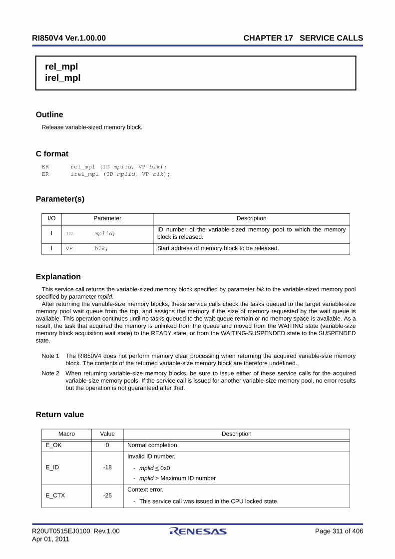
RI850V4 Ver.1.00.00 CHAPTER 17 SERVICE CALLS
R20UT0515EJ0100 Rev.1.00 Page 311 of 406Apr 01, 2011
rel_mplirel_mpl
Outline
Release variable-sized memory block.
C format
ER rel_mpl (ID mplid, VP blk);ER irel_mpl (ID mplid, VP blk);
Parameter(s)
Explanation
This service call returns the variable-sized memory block specified by parameter blk to the variable-sized memory poolspecified by parameter mplid.
After returning the variable-size memory blocks, these service calls check the tasks queued to the target variable-sizememory pool wait queue from the top, and assigns the memory if the size of memory requested by the wait queue isavailable. This operation continues until no tasks queued to the wait queue remain or no memory space is available. As aresult, the task that acquired the memory is unlinked from the queue and moved from the WAITING state (variable-sizememory block acquisition wait state) to the READY state, or from the WAITING-SUSPENDED state to the SUSPENDEDstate.
Note 1 The RI850V4 does not perform memory clear processing when returning the acquired variable-size memoryblock. The contents of the returned variable-size memory block are therefore undefined.
Note 2 When returning variable-size memory blocks, be sure to issue either of these service calls for the acquiredvariable-size memory pools. If the service call is issued for another variable-size memory pool, no error resultsbut the operation is not guaranteed after that.
Return value
I/O Parameter Description
I ID mplid;ID number of the variable-sized memory pool to which the memoryblock is released.
I VP blk; Start address of memory block to be released.
Macro Value Description
E_OK 0 Normal completion.
E_ID -18
Invalid ID number.
- mplid < 0x0
- mplid > Maximum ID number
E_CTX -25Context error.
- This service call was issued in the CPU locked state.
RI850V4 Ver.1.00.00 CHAPTER 17 SERVICE CALLS
R20UT0515EJ0100 Rev.1.00 Page 312 of 406Apr 01, 2011
E_NOEXS -42Non-existent object.
- Specified variable-sized memory pool is not registered.
Macro Value Description

RI850V4 Ver.1.00.00 CHAPTER 17 SERVICE CALLS
R20UT0515EJ0100 Rev.1.00 Page 313 of 406Apr 01, 2011
ref_mpliref_mpl
Outline
Reference variable-sized memory pool state.
C format
ER ref_mpl (ID mplid, T_RMPL *pk_rmpl);ER iref_mpl (ID mplid, T_RMPL *pk_rmpl);
Parameter(s)
[Variable-sized memory pool state packet: T_RMPL]
Explanation
These service calls store the detailed information (ID number of the task at the head of the wait queue, total size of freememory blocks, etc.) of the variable-size memory pool specified by parameter mplid into the area specified by parameterpk_rmpl.
Note For details about the variable-sized memory pool state packet, refer to "16.2.11 Variable-sized memory poolstate packet".
Return value
I/O Parameter Description
I ID mplid; ID number of the variable-sized memory pool to be referenced.
O T_RMPL *pk_rmpl; Pointer to the packet returning the variable-sized memory pool state.
typedef struct t_rmpl { ID wtskid; /*Existence of waiting task*/ SIZE fmplsz; /*Total size of free memory blocks*/ UINT fblksz; /*Maximum memory blocK size available*/ ATR mplatr; /*Attribute*/ ID memid; /*Reserved for future use*/} T_RMPL;
Macro Value Description
E_OK 0 Normal completion.
E_ID -18
Invalid ID number.
- mplid < 0x0
- mplid > Maximum ID number

RI850V4 Ver.1.00.00 CHAPTER 17 SERVICE CALLS
R20UT0515EJ0100 Rev.1.00 Page 314 of 406Apr 01, 2011
E_CTX -25Context error.
- This service call was issued in the CPU locked state.
E_NOEXS -42Non-existent object.
- Specified variable-sized memory pool is not registered.
Macro Value Description
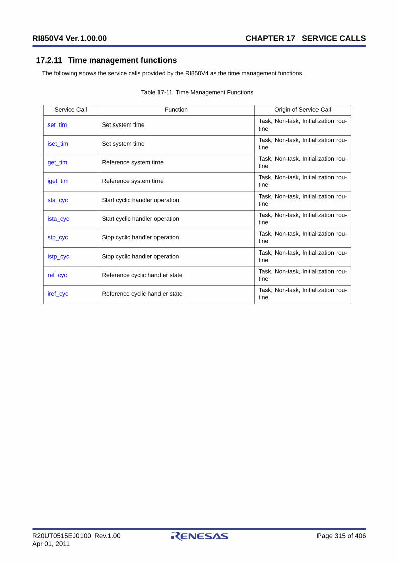
RI850V4 Ver.1.00.00 CHAPTER 17 SERVICE CALLS
R20UT0515EJ0100 Rev.1.00 Page 315 of 406Apr 01, 2011
17.2.11 Time management functions
The following shows the service calls provided by the RI850V4 as the time management functions.
Table 17-11 Time Management Functions
Service Call Function Origin of Service Call
set_tim Set system time Task, Non-task, Initialization rou-tine
iset_tim Set system time Task, Non-task, Initialization rou-tine
get_tim Reference system time Task, Non-task, Initialization rou-tine
iget_tim Reference system time Task, Non-task, Initialization rou-tine
sta_cyc Start cyclic handler operation Task, Non-task, Initialization rou-tine
ista_cyc Start cyclic handler operation Task, Non-task, Initialization rou-tine
stp_cyc Stop cyclic handler operation Task, Non-task, Initialization rou-tine
istp_cyc Stop cyclic handler operation Task, Non-task, Initialization rou-tine
ref_cyc Reference cyclic handler state Task, Non-task, Initialization rou-tine
iref_cyc Reference cyclic handler state Task, Non-task, Initialization rou-tine
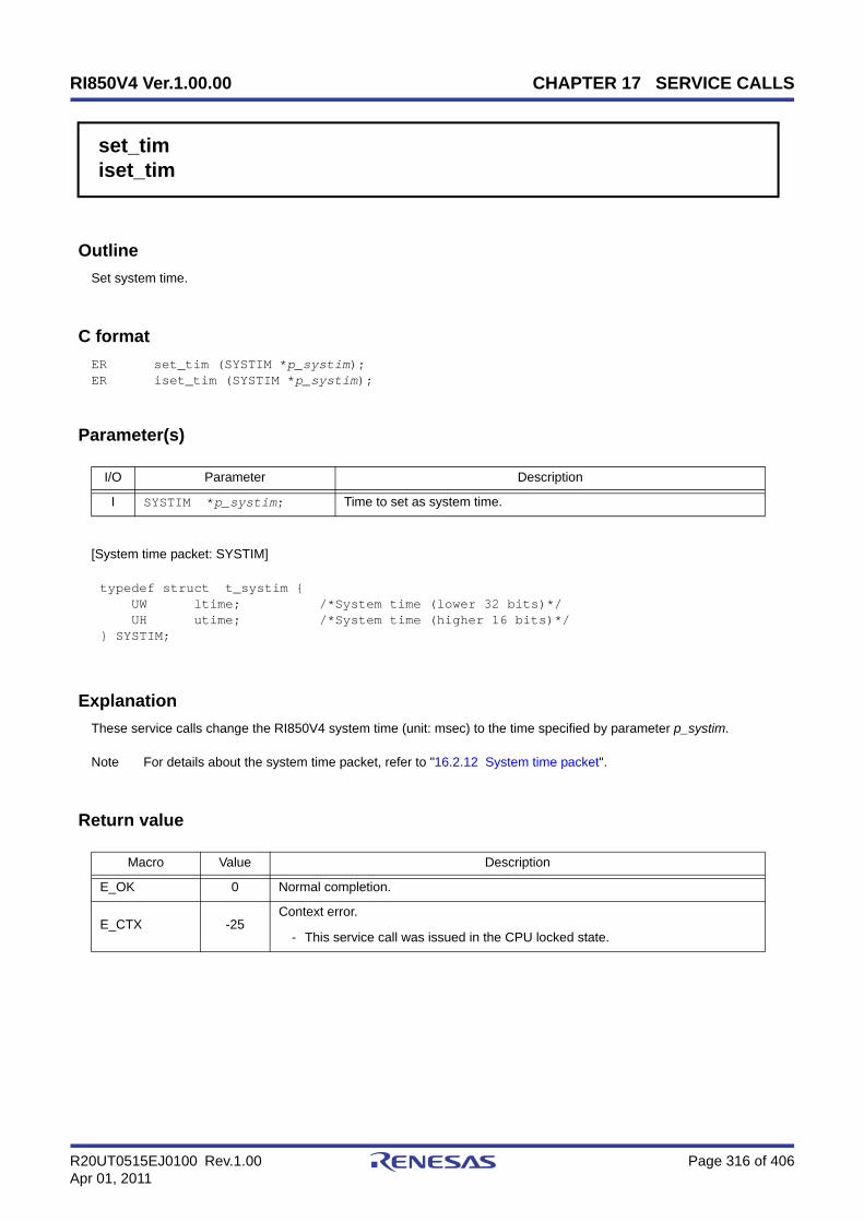
RI850V4 Ver.1.00.00 CHAPTER 17 SERVICE CALLS
R20UT0515EJ0100 Rev.1.00 Page 316 of 406Apr 01, 2011
set_timiset_tim
Outline
Set system time.
C format
ER set_tim (SYSTIM *p_systim);ER iset_tim (SYSTIM *p_systim);
Parameter(s)
[System time packet: SYSTIM]
Explanation
These service calls change the RI850V4 system time (unit: msec) to the time specified by parameter p_systim.
Note For details about the system time packet, refer to "16.2.12 System time packet".
Return value
I/O Parameter Description
I SYSTIM *p_systim; Time to set as system time.
typedef struct t_systim { UW ltime; /*System time (lower 32 bits)*/ UH utime; /*System time (higher 16 bits)*/} SYSTIM;
Macro Value Description
E_OK 0 Normal completion.
E_CTX -25Context error.
- This service call was issued in the CPU locked state.

RI850V4 Ver.1.00.00 CHAPTER 17 SERVICE CALLS
R20UT0515EJ0100 Rev.1.00 Page 317 of 406Apr 01, 2011
get_timiget_tim
Outline
Reference system time.
C format
ER get_tim (SYSTIM *p_systim);ER iget_tim (SYSTIM *p_systim);
Parameter(s)
[System time packet: SYSTIM]
Explanation
These service calls store the RI850V4 system time (unit: msec) into the area specified by parameter p_systim.
Note 1 The RI850V4 ignores the numeric values that cannot be expressed as the system time (values overflowedfrom the 48-bit width).
Note 2 For details about the system time packet, refer to "16.2.12 System time packet".
Return value
I/O Parameter Description
O SYSTIM *p_systim; Current system time.
typedef struct t_systim { UW ltime; /*System time (lower 32 bits)*/ UH utime; /*System time (higher 16 bits)*/} SYSTIM;
Macro Value Description
E_OK 0 Normal completion.
E_CTX -25Context error.
- This service call was issued in the CPU locked state.

RI850V4 Ver.1.00.00 CHAPTER 17 SERVICE CALLS
R20UT0515EJ0100 Rev.1.00 Page 318 of 406Apr 01, 2011
sta_cycista_cyc
Outline
Start cyclic handler operation.
C format
ER sta_cyc (ID cycid);ER ista_cyc (ID cycid);
Parameter(s)
Explanation
This service call moves the cyclic handler specified by parameter cycid from the non-operational state (STP state) tooperational state (STA state).
As a result, the target cyclic handler is handled as an activation target of the RI850V4.The relative interval from when either of this service call is issued until the first activation request is issued varies
depending on whether the TA_PHS attribute is specified for the target cyclic handler during configuration.
- If the TA_PHS attribute is specifiedThe target cyclic handler activation timing is set based on the activation phases (initial activation phase cycphs andactivation cycle cyctim) defined during configuration.If the target cyclic handler has already been started, however, no processing is performed even if this service call isissued, but it is not handled as an error.
- If the TA_PHS attribute is not specifiedThe target cyclic handler activation timing is set based on the activation phase (activation cycle cyctim) when thisservice call is issued.This setting is performed regardless of the operating status of the target cyclic handler.
Return value
I/O Parameter Description
I ID cycid; ID number of the cyclic handler operation to be started.
Macro Value Description
E_OK 0 Normal completion.
E_ID -18
Invalid ID number.
- cycid < 0x0
- cycid > Maximum ID number
E_CTX -25Context error.
- This service call was issued in the CPU locked state.

RI850V4 Ver.1.00.00 CHAPTER 17 SERVICE CALLS
R20UT0515EJ0100 Rev.1.00 Page 319 of 406Apr 01, 2011
E_NOEXS -42Non-existent object.
- Specified cyclic handler is not registered.
Macro Value Description
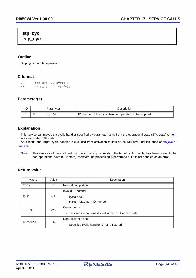
RI850V4 Ver.1.00.00 CHAPTER 17 SERVICE CALLS
R20UT0515EJ0100 Rev.1.00 Page 320 of 406Apr 01, 2011
stp_cycistp_cyc
Outline
Stop cyclic handler operation.
C format
ER stp_cyc (ID cycid);ER istp_cyc (ID cycid);
Parameter(s)
Explanation
This service call moves the cyclic handler specified by parameter cycid from the operational state (STA state) to non-operational state (STP state).
As a result, the target cyclic handler is excluded from activation targets of the RI850V4 until issuance of sta_cyc orista_cyc.
Note This service call does not perform queuing of stop requests. If the target cyclic handler has been moved to thenon-operational state (STP state), therefore, no processing is performed but it is not handled as an error.
Return value
I/O Parameter Description
I ID cycid; ID number of the cyclic handler operation to be stopped.
Macro Value Description
E_OK 0 Normal completion.
E_ID -18
Invalid ID number.
- cycid < 0x0
- cycid > Maximum ID number
E_CTX -25Context error.
- This service call was issued in the CPU locked state.
E_NOEXS -42Non-existent object.
- Specified cyclic handler is not registered.

RI850V4 Ver.1.00.00 CHAPTER 17 SERVICE CALLS
R20UT0515EJ0100 Rev.1.00 Page 321 of 406Apr 01, 2011
ref_cyciref_cyc
Outline
Reference cyclic handler state.
C format
ER ref_cyc (ID cycid, T_RCYC *pk_rcyc);ER iref_cyc (ID cycid, T_RCYC *pk_rcyc);
Parameter(s)
[Cyclic handler state packet: T_RCYC]
Explanation
Stores cyclic handler state packet (current state, time left before the next activation, etc.) of the cyclic handler specifiedby parameter cycid in the area specified by parameter pk_rcyc.
Note For details about the cyclic handler state packet, refer to "16.2.13 Cyclic handler state packet".
Return value
I/O Parameter Description
I ID cycid; ID number of the cyclic handler to be referenced.
O T_RCYC *pk_rcyc; Pointer to the packet returning the cyclic handler state.
typedef struct t_rcyc { STAT cycstat; /*Current state*/ RELTIM lefttim; /*Time left before the next activation*/ ATR cycatr; /*Attribute*/ RELTIM cyctim; /*Activation cycle*/ RELTIM cycphs; /*Activation phase*/} T_RCYC;
Macro Value Description
E_OK 0 Normal completion.
E_ID -18
Invalid ID number.
- cycid < 0x0
- cycid > Maximum ID number
E_CTX -25Context error.
- This service call was issued in the CPU locked state.

RI850V4 Ver.1.00.00 CHAPTER 17 SERVICE CALLS
R20UT0515EJ0100 Rev.1.00 Page 322 of 406Apr 01, 2011
E_NOEXS -42Non-existent object.
- Specified cyclic handler is not registered.
Macro Value Description

RI850V4 Ver.1.00.00 CHAPTER 17 SERVICE CALLS
R20UT0515EJ0100 Rev.1.00 Page 323 of 406Apr 01, 2011
17.2.12 System state management functions
The following shows the service calls provided by the RI850V4 as the system state management functions.
Table 17-12 System State Management Functions
Service Call Function Origin of Service Call
rot_rdq Rotate task precedence Task, Non-task, Initialization rou-tine
irot_rdq Rotate task precedence Task, Non-task, Initialization rou-tine
vsta_sch Forced scheduler activation Task
get_tid Reference task ID in the RUNNING state Task, Non-task, Initialization rou-tine
iget_tid Reference task ID in the RUNNING state Task, Non-task, Initialization rou-tine
loc_cpu Lock the CPU Task, Non-task
iloc_cpu Lock the CPU Task, Non-task
unl_cpu Unlock the CPU Task, Non-task
iunl_cpu Unlock the CPU Task, Non-task
sns_loc Reference CPU state Task, Non-task, Initialization rou-tine
dis_dsp Disable dispatching Task
ena_dsp Enable dispatching Task
sns_dsp Reference dispatching state Task, Non-task, Initialization rou-tine
sns_ctx Reference contexts Task, Non-task, Initialization rou-tine
sns_dpn Reference dispatching pending state Task, Non-task, Initialization rou-tine

RI850V4 Ver.1.00.00 CHAPTER 17 SERVICE CALLS
R20UT0515EJ0100 Rev.1.00 Page 324 of 406Apr 01, 2011
rot_rdqirot_rdq
Outline
Rotate task precedence.
C fomrat
ER rot_rdq (PRI tskpri);ER irot_rdq (PRI tskpri);
Parameter(s)
Explanation
This service call re-queues the first task of the ready queue corresponding to the priority specified by parameter tskpri tothe end of the queue to change the task execution order explicitly.
Note 1 This service call does not perform queuing of rotation requests. If no task is queued to the ready queuecorresponding to the relevant priority, therefore, no processing is performed but it is not handled as an error.
Note 2 Round-robin scheduling can be implemented by issuing this service call via a cyclic handler in a constantcycle.
Note 3 The ready queue is a hash table that uses priority as the key, and tasks that have entered an executable state(READY state or RUNNING state) are queued in FIFO order.Therefore, the scheduler realizes the RI850V4's scheduling system by executing task detection processingfrom the highest priority level of the ready queue upon activation, and upon detection of queued tasks, givingthe CPU use right to the first task of the proper priority level.
Return value
I/O Parameter Description
I PRI tskpri;
Priority of the tasks whose precedence is rotated.
TPRI_SELF: Current priority of the invoking task.Value: Priority of the tasks whose precedence is rotated.
Macro Value Description
E_OK 0 Normal completion.
E_PAR -17
Parameter error.
- tskpri < 0x0
- tskpri > Maximum priority
- When this service call was issued from a non-task, TPRI_SELF was specifiedtskpri.
E_CTX -25Context error.
- This service call was issued in the CPU locked state.
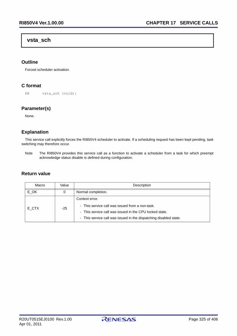
RI850V4 Ver.1.00.00 CHAPTER 17 SERVICE CALLS
R20UT0515EJ0100 Rev.1.00 Page 325 of 406Apr 01, 2011
vsta_sch
Outline
Forced scheduler activation.
C format
ER vsta_sch (void);
Parameter(s)
None.
Explanation
This service call explicitly forces the RI850V4 scheduler to activate. If a scheduling request has been kept pending, taskswitching may therefore occur.
Note The RI850V4 provides this service call as a function to activate a scheduler from a task for which preemptacknowledge status disable is defined during configuration.
Return value
Macro Value Description
E_OK 0 Normal completion.
E_CTX -25
Context error.
- This service call was issued from a non-task.
- This service call was issued in the CPU locked state.
- This service call was issued in the dispatching disabled state.
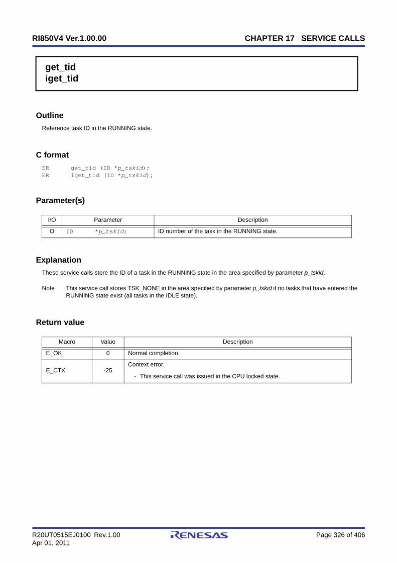
RI850V4 Ver.1.00.00 CHAPTER 17 SERVICE CALLS
R20UT0515EJ0100 Rev.1.00 Page 326 of 406Apr 01, 2011
get_tidiget_tid
Outline
Reference task ID in the RUNNING state.
C format
ER get_tid (ID *p_tskid);ER iget_tid (ID *p_tskid);
Parameter(s)
Explanation
These service calls store the ID of a task in the RUNNING state in the area specified by parameter p_tskid.
Note This service call stores TSK_NONE in the area specified by parameter p_tskid if no tasks that have entered theRUNNING state exist (all tasks in the IDLE state).
Return value
I/O Parameter Description
O ID *p_tskid; ID number of the task in the RUNNING state.
Macro Value Description
E_OK 0 Normal completion.
E_CTX -25Context error.
- This service call was issued in the CPU locked state.

RI850V4 Ver.1.00.00 CHAPTER 17 SERVICE CALLS
R20UT0515EJ0100 Rev.1.00 Page 327 of 406Apr 01, 2011
loc_cpuiloc_cpu
Outline
Lock the CPU.
C format
ER loc_cpu (void);ER iloc_cpu (void);
Parameter(s)
None.
Explanation
These service calls change the system status type to the CPU locked state.As a result, maskable interrupt acknowledgment processing is prohibited during the interval from this service call is
issued until unl_cpu or iunl_cpu is issued, and service call issuance is also restricted.The service calls that can be issued in the CPU locked state are limited to the one listed below.
If a maskable interrupt is created during this period, the RI850V4 delays transition to the relevant interrupt processing(interrupt handler) until either unl_cpu or iunl_cpu is issued.
Note 1 The internal processing (interrupt mask setting processing and interrupt mask acquire processing) performedby this service call depends on the user execution environment, so it is extracted as a target-dependentmodule and provided as sample source files.In sample source files, manipulation for the interrupt control register xxICn and the interrupt mask flag xxMKnof the interrupt mask register IMRm is coded as interrupt mask setting processing or interrupt mask acquireprocessing.
Note 2 The CPU locked state changed by issuing this service call must be cancelled before the processing programthat issued this service call ends.
Note 3 This service call does not perform queuing of lock requests. If the system is in the CPU locked state, therefore,no processing is performed but it is not handled as an error.
Note 4 The RI850V4 realizes the TIME MANAGEMENT FUNCTIONS by using base clock timer interrupts that occurat constant intervals. If acknowledgment of the relevant base clock timer interrupt is disabled by issuing thisservice call, the TIME MANAGEMENT FUNCTIONS may no longer operate normally.
Service Call Function
sns_tex Reference task exception handling state.
loc_cpu, iloc_cpu Lock the CPU.
unl_cpu, iunl_cpu Unlock the CPU.
sns_loc Reference CPU state.
sns_dsp Reference dispatching state.
sns_ctx Reference contexts.
sns_dpn Reference dispatch pending state.
RI850V4 Ver.1.00.00 CHAPTER 17 SERVICE CALLS
R20UT0515EJ0100 Rev.1.00 Page 328 of 406Apr 01, 2011
Note 5 If this service call or a service call other than sns_xxx is issued from when this service call is issued untilunl_cpu or iunl_cpu is issued, the RI850V4 returns E_CTX.
Return value
Macro Value Description
E_OK 0 Normal completion.
RI850V4 Ver.1.00.00 CHAPTER 17 SERVICE CALLS
R20UT0515EJ0100 Rev.1.00 Page 329 of 406Apr 01, 2011
unl_cpuiunl_cpu
Outline
Unlock the CPU.
C format
ER unl_cpu (void);ER iunl_cpu (void);
Parameter(s)
None.
Explanation
These service calls change the system status to the CPU unlocked state.As a result, acknowledge processing of maskable interrupts prohibited through issuance of either loc_cpu or iloc_cpu is
enabled, and the restriction on service call issuance is released.If a maskable interrupt is created during the interval from when either loc_cpu or iloc_cpu is issued until this service call
is issued, the RI850V4 delays transition to the relevant interrupt processing (interrupt handler) until this service call isissued.
Note 1 The internal processing (interrupt mask setting processing) performed by this service call depends on the userexecution environment, so it is extracted as a target-dependent module and provided as sample source files.In sample source files, manipulation for the interrupt control register xxICn and the interrupt mask flag xxMKnof the interrupt mask register IMRm is coded as interrupt mask setting processing.
Note 2 This service call does not perform queuing of cancellation requests. If the system is in the CPU unlocked state,therefore, no processing is performed but it is not handled as an error.
Note 3 This service call does not cancel the dispatch disabled state that was set by issuing dis_dsp. If the systemstatus before the CPU locked state is entered was the dispatch disabled state, the system status becomes thedispatch disabled state after this service call is issued.
Note 4 This service call does not enable acknowledgment of the maskable interrupts that has been disabled byissuing dis_int. If the system status before the CPU locked state is entered was the maskable interruptacknowledgment enabled state, acknowledgment of maskable interrupts is disabled after this service call isissued.
Note 5 If a service call other than loc_cpu, iloc_cpu and sns_xxx is issued from when loc_cpu or iloc_cpu is issueduntil this service call is issued, the RI850V4 returns E_CTX.
Return value
Macro Value Description
E_OK 0 Normal completion.

RI850V4 Ver.1.00.00 CHAPTER 17 SERVICE CALLS
R20UT0515EJ0100 Rev.1.00 Page 330 of 406Apr 01, 2011
sns_loc
Outline
Reference CPU state.
C format
BOOL sns_loc (void);
Parameter(s)
None.
Explanation
This service call acquires the system status type when this service call is issued (CPU locked state or CPU unlockedstate).
When this service call is terminated normally, the acquired system state type (TRUE: CPU locked state, FALSE: CPUunlocked state) is returned.
Return value
Macro Value Description
TRUE 1 Normal completion (CPU locked state).
FALSE 0 Normal completion (CPU unlocked state).

RI850V4 Ver.1.00.00 CHAPTER 17 SERVICE CALLS
R20UT0515EJ0100 Rev.1.00 Page 331 of 406Apr 01, 2011
dis_dsp
Outline
Disable dispatching.
C format
ER dis_dsp (void);
Parameter(s)
None.
Explanation
This service call changes the system status to the dispatch disabled state.As a result, dispatch processing (task scheduling) is disabled from when this service call is issued until ena_dsp is
issued.If a service call (chg_pri, sig_sem, etc.) accompanying dispatch processing is issued during the interval from when this
service call is issued until ena_dsp is issued, the RI850V4 executes only processing such as queue manipulation, countermanipulation, etc., and the actual dispatch processing is delayed until ena_dsp is issued, upon which the actual dispatchprocessing is performed in batch.
Note 1 The dispatch disabled state changed by issuing this service call must be cancelled before the task that issuedthis service call moves to the DORMANT state.
Note 2 This service call does not perform queuing of disable requests. If the system is in the dispatch disabled state,therefore, no processing is performed but it is not handled as an error.
Note 3 If a service call (such as wai_sem, wai_flg) that may move the status of an invoking task is issued from whenthis service call is issued until ena_dsp is issued, the RI850V4 returns E_CTX regardless of whether therequired condition is immediately satisfied.
Return value
Macro Value Description
E_OK 0 Normal completion.
E_CTX -25
Context error.
- This service call was issued from a non-task.
- This service call was issued in the CPU locked state.

RI850V4 Ver.1.00.00 CHAPTER 17 SERVICE CALLS
R20UT0515EJ0100 Rev.1.00 Page 332 of 406Apr 01, 2011
ena_dsp
Outline
Enable dispatching.
C format
ER ena_dsp (void);
Parameter(s)
None.
Explanation
This service call changes the system status to the dispatch enabled state.As a result, dispatch processing (task scheduling) that has been disabled by issuing dis_dsp is enabled.If a service call (chg_pri, sig_sem, etc.) accompanying dispatch processing is issued during the interval from when
dis_dsp is issued until this service call is issued, the RI850V4 executes only processing such as queue manipulation,counter manipulation, etc., and the actual dispatch processing is delayed until this service call is issued, upon which theactual dispatch processing is performed in batch.
Note 1 This service call does not perform queuing of enable requests. If the system is in the dispatch enabled state,therefore, no processing is performed but it is not handled as an error.
Note 2 If a service call (such as wai_sem, wai_flg) that may move the status of an invoking task is issued from whendis_dsp is issued until this service call is issued, the RI850V4 returns E_CTX regardless of whether therequired condition is immediately satisfied.
Return value
Macro Value Description
E_OK 0 Normal completion.
E_CTX -25
Context error.
- This service call was issued from a non-task.
- This service call was issued in the CPU locked state.
RI850V4 Ver.1.00.00 CHAPTER 17 SERVICE CALLS
R20UT0515EJ0100 Rev.1.00 Page 333 of 406Apr 01, 2011
sns_dsp
Outline
Reference dispatching state.
C format
BOOL sns_dsp (void);
Parameter(s)
None.
Explanation
This service call acquires the system status type when this service call is issued (dispatch disabled state or dispatchenabled state).
When this service call is terminated normally, the acquired system state type (TRUE: dispatch disabled state, FALSE:dispatch enabled state) is returned.
Return value
Macro Value Description
TRUE 1 Normal completion (dispatching disabled state).
FALSE 0 Normal completion (dispatching enabled state).

RI850V4 Ver.1.00.00 CHAPTER 17 SERVICE CALLS
R20UT0515EJ0100 Rev.1.00 Page 334 of 406Apr 01, 2011
sns_ctx
Outline
Reference contexts.
C format
BOOL sns_ctx (void);
Parameter(s)
None.
Explanation
This service call acquires the context type of the processing program that issued this service call (non-task context ortask context).
When this service call is terminated normally, the acquired context type (TRUE: non-task context, FALSE: task context)is returned.
Return value
Macro Value Description
TRUE 1 Normal completion (non-task contexts).
FALSE 0 Normal completion (task contexts).
RI850V4 Ver.1.00.00 CHAPTER 17 SERVICE CALLS
R20UT0515EJ0100 Rev.1.00 Page 335 of 406Apr 01, 2011
sns_dpn
Outline
Reference dispatch pending state.
C format
BOOL sns_dpn (void);
Parameter(s)
None.
Explanation
This service call acquires the system status type when this service call is issued (whether in dispatch pending state ornot).
When this service call is terminated normally, the acquired system state type (TRUE: dispatch pending state, FALSE:dispatch not-pending state) is returned.
Return value
Macro Value Description
TRUE 1 Normal completion. (dispatch pending state)
FALSE 0 Normal completion. (any other states)
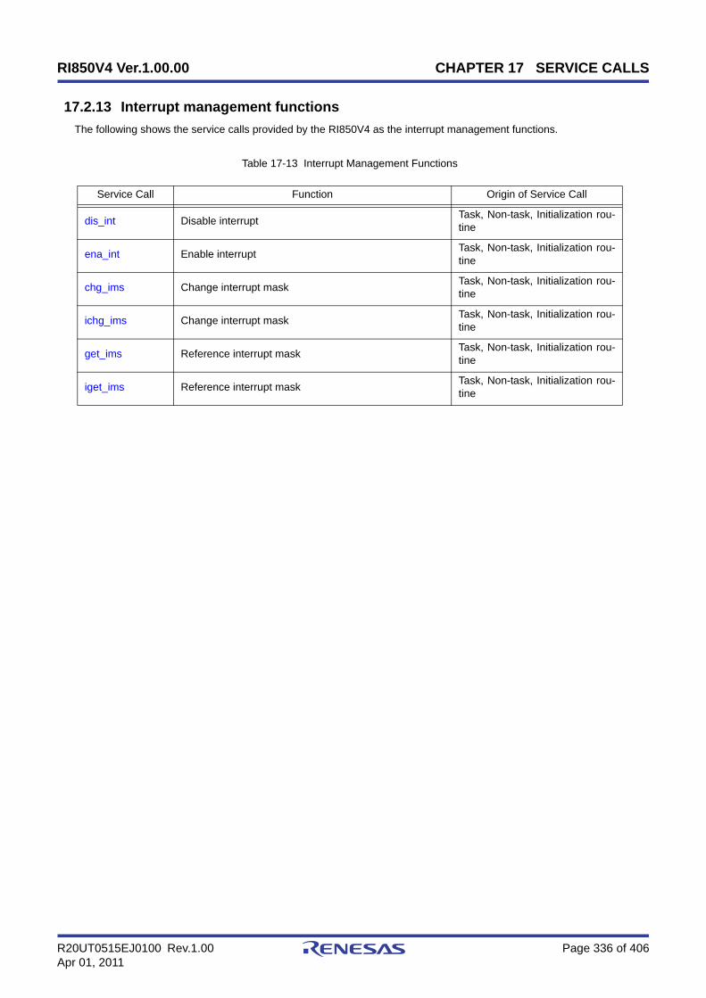
RI850V4 Ver.1.00.00 CHAPTER 17 SERVICE CALLS
R20UT0515EJ0100 Rev.1.00 Page 336 of 406Apr 01, 2011
17.2.13 Interrupt management functions
The following shows the service calls provided by the RI850V4 as the interrupt management functions.
Table 17-13 Interrupt Management Functions
Service Call Function Origin of Service Call
dis_int Disable interrupt Task, Non-task, Initialization rou-tine
ena_int Enable interrupt Task, Non-task, Initialization rou-tine
chg_ims Change interrupt mask Task, Non-task, Initialization rou-tine
ichg_ims Change interrupt mask Task, Non-task, Initialization rou-tine
get_ims Reference interrupt mask Task, Non-task, Initialization rou-tine
iget_ims Reference interrupt mask Task, Non-task, Initialization rou-tine

RI850V4 Ver.1.00.00 CHAPTER 17 SERVICE CALLS
R20UT0515EJ0100 Rev.1.00 Page 337 of 406Apr 01, 2011
dis_int
Outline
Disable interrupt.
C format
ER dis_int (INTNO intno);
Parameter(s)
Explanation
This service call disables acknowledgment of maskable interrupts corresponding to the exception code specified byparameter intno.
If a maskable interrupt corresponding to the exception code specified by parameter intno occurs from when this servicecall is issued until ena_int is issued, the RI850V4 delays branching to the relevant interrupt servicing (interrupt handler)until ena_int is issued.
Note 1 The processing performed by this service call depends on the user execution environment, so it is extracted asa target-dependent module and provided as sample source files.In sample source files, manipulation for the interrupt control register xxICn and the interrupt mask flag xxMKnof the interrupt mask register IMRm is coded as processing to disable acknowledgment of maskable interrupt.
Note 2 This service call does not perform queuing of disable requests. If this service call has already been issued andacknowledgment of the corresponding maskable interrupt has been disabled, therefore, no processing isperformed but it is not handled as an error.
Note 3 The RI850V4 realizes the TIME MANAGEMENT FUNCTIONS by using base clock timer interrupts that occurat constant intervals. If acknowledgment of the relevant base clock timer interrupt is disabled by issuing thisservice call, the TIME MANAGEMENT FUNCTIONS may no longer operate normally.
Return value
I/O Parameter Description
I INTNO intno; Exception code to be disabled.
Macro Value Description
E_OK 0 Normal completion.
E_PAR -17Parameter error.
- intno is invalid.
E_CTX -25Context error.
- This service call was issued in the CPU locked state.

RI850V4 Ver.1.00.00 CHAPTER 17 SERVICE CALLS
R20UT0515EJ0100 Rev.1.00 Page 338 of 406Apr 01, 2011
ena_int
Outline
Enable interrupt.
C format
ER ena_int (INTNO intno);
Parameter(s)
Explanation
This service call enables acknowledgment of maskable interrupts corresponding to the exception code specified byparameter intno.
If a maskable interrupt corresponding to the exception code specified by parameter intno occurs from when dis_int isissued until this service call is issued, the RI850V4 delays branching to the relevant interrupt servicing (interrupt handler)until this service call is issued.
Note 1 The processing performed by this service call depends on the user execution environment, so it is extracted asa target-dependent module and provided as sample source files.In sample source files, manipulation for the interrupt control register xxICn and the interrupt mask flag xxMKnof the interrupt mask register IMRm is coded as processing to enable acknowledgment of maskable interrupt.
Note 2 This service call does not perform queuing of enable requests. If this service call has already been issued andacknowledgment of the corresponding maskable interrupt has been enabled, therefore, no processing isperformed but it is not handled as an error.
Return value
I/O Parameter Description
I INTNO intno; Exception code to be enabled.
Macro Value Description
E_OK 0 Normal completion.
E_PAR -17Parameter error.
- intno is invalid.
E_CTX -25Context error.
- This service call was issued in the CPU locked state.

RI850V4 Ver.1.00.00 CHAPTER 17 SERVICE CALLS
R20UT0515EJ0100 Rev.1.00 Page 339 of 406Apr 01, 2011
chg_imsichg_ims
Outline
Change interrupt mask.
C format
ER chg_ims (UH *p_intms);ER ichg_ims (UH *p_intms);
Parameter(s)
Explanation
These service calls change the CPU interrupt mask pattern (value of interrupt control register xxICn or interrupt maskflag xxMKn of interrupt mask register IMRm) to the state specified by parameter p_intms.
The following shows the meaning of values to be set (interrupt mask flag) to the area specified by p_intms.
0: Acknowledgment of maskable interrupts is enabled1: Acknowledgment of maskable interrupts is disabled
Note 1 The internal processing (interrupt mask setting processing) performed by this service call depends on the userexecution environment, so it is extracted as a target-dependent module and provided as sample source files.
Note 2 The RI850V4 realizes the TIME MANAGEMENT FUNCTIONS by using base clock timer interrupts that occurat constant intervals. If acknowledgment of the relevant base clock timer interrupt is disabled by issuing thisservice call, the TIME MANAGEMENT FUNCTIONS may no longer operate normally.
Return value
I/O Parameter Description
I UH *p_intms; Interrupt mask desired.
Macro Value Description
E_OK 0 Normal completion.
E_CTX -25Context error.
- This service call was issued in the CPU locked state.

RI850V4 Ver.1.00.00 CHAPTER 17 SERVICE CALLS
R20UT0515EJ0100 Rev.1.00 Page 340 of 406Apr 01, 2011
get_imsiget_ims
Outline
Reference interrupt mask.
C format
ER get_ims (UH *p_intms);ER iget_ims (UH *p_intms);
Parameter(s)
Explanation
These service calls store the CPU interrupt mask pattern (value of interrupt control register xxICn or interrupt mask flagxxMKn of interrupt mask register IMRm) into the area specified by parameter p_intms.
The following shows the meaning of values to be stored (interrupt mask flag) into the area specified by p_intms.
0: Acknowledgment of maskable interrupts is enabled1: Acknowledgment of maskable interrupts is disabled
Note The internal processing (interrupt mask acquire processing) performed by this service call depends on the userexecution environment, so it is extracted as a target-dependent module and provided as sample source files.
Return value
I/O Parameter Description
O UH *p_intms; Current interrupt mask.
Macro Value Description
E_OK 0 Normal completion.
E_CTX -25Context error.
- This service call was issued in the CPU locked state.

RI850V4 Ver.1.00.00 CHAPTER 17 SERVICE CALLS
R20UT0515EJ0100 Rev.1.00 Page 341 of 406Apr 01, 2011
17.2.14 Service call management functions
The following shows the service calls provided by the RI850V4 as the service call management functions.
Table 17-14 Service Call Management Functions
Service Call Function Origin of Service Call
cal_svc Invoke extended service call routine Task, Non-task, Initialization rou-tine
ical_svc Invoke extended service call routine Task, Non-task, Initialization rou-tine
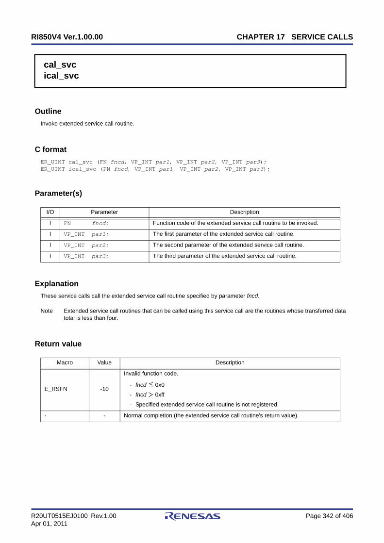
RI850V4 Ver.1.00.00 CHAPTER 17 SERVICE CALLS
R20UT0515EJ0100 Rev.1.00 Page 342 of 406Apr 01, 2011
cal_svcical_svc
Outline
Invoke extended service call routine.
C format
ER_UINT cal_svc (FN fncd, VP_INT par1, VP_INT par2, VP_INT par3);ER_UINT ical_svc (FN fncd, VP_INT par1, VP_INT par2, VP_INT par3);
Parameter(s)
Explanation
These service calls call the extended service call routine specified by parameter fncd.
Note Extended service call routines that can be called using this service call are the routines whose transferred datatotal is less than four.
Return value
I/O Parameter Description
I FN fncd; Function code of the extended service call routine to be invoked.
I VP_INT par1; The first parameter of the extended service call routine.
I VP_INT par2; The second parameter of the extended service call routine.
I VP_INT par3; The third parameter of the extended service call routine.
Macro Value Description
E_RSFN -10
Invalid function code.
- fncd ≦ 0x0
- fncd > 0xff
- Specified extended service call routine is not registered.
- - Normal completion (the extended service call routine's return value).

RI850V4 Ver.1.00.00 CHAPTER 18 SYSTEM CONFIGURATION FILE
R20UT0515EJ0100 Rev.1.00 Page 343 of 406Apr 01, 2011
CHAPTER 18 SYSTEM CONFIGURATION FILE
This chapter explains the coding method of the system configuration file required to output information files (systeminformation table file, system information header file and entry file) that contain data to be provided for the RI850V4.
18.1 Outline
The following shows the notation method of system configuration files.
- Character codeCreate the system configuration file using ASCII code.The CF850V4 distinguishes lower cases "a to z" and upper cases "A to Z".
Note For japanese language coding, Shit-JIS codes can be used only for comments.
- CommentIn a system configuration file, parts between /* and */ and parts from two successive slashes (//) to the line end areregarded as comments.
- NumericIn a system configuration file, words starting with a numeric value (0 to 9) are regarded as numeric values.The CFV850V4 distinguishes numeric values as follows.
Octal: Words starting with 0Decimal: Words starting with a value other than 0Hexadecimal: Words starting with 0x or 0X
Note Unless specified otherwise, the range of values that can be specified as numeric values are limited from 0x0to 0xffffffff.
- Symbol nameIn a system configuration file, words starting with an alphabetic character, "a to z, A to Z", or underscore "_" areregarded as symbol names.Describing a symbol name in the format "symbol name + offset" is also possible, but the offset must be a constantexpression.The following shows examples of describing symbol names.The CF850V4 distinguishes between symbol names and other names based on the context in the systemconfiguration file.
[Correct] func + 0x80000 // func name symbol + 0x90 * 80 // symbol name symbol + BASE // data macro
[Incorrect] (func + 0x8000) // The start character is illegal. 0x8000 + func // The start character is illegal. BASE + func // Data macro BASE is handled as a symbol name. func * 0x8000 // It is not the format of offset.
Note Up to 4,095 characters can be specified for symbol names, including offset and spaces.
- NameIn a system configuration file, words starting with an alphabetic character, "a to z, A to Z", or underscore "_" areregarded as names.The CF850V4 distinguishes between symbol names and other names based on the context in the systemconfiguration file.
Note Up to 255 characters can be specified for names.

RI850V4 Ver.1.00.00 CHAPTER 18 SYSTEM CONFIGURATION FILE
R20UT0515EJ0100 Rev.1.00 Page 344 of 406Apr 01, 2011
- Preprocessing directivesThe following preprocessing directives can be coded in a system configuration file.
#define, #elif, #else, #endif, #if, #ifdef, #ifndef, #include, #undef
- KeywordsThe words shown below are reserved by the CFV850V4 as keywords.Using these words for any other purpose specified is therefore prohibited.
ATT_INI, CLK_INTNO, CPU_TYPE, CRE_CYC, CRE_DTQ, CRE_FLG, CRE_MBX, CRE_MPF, CRE_MPL,CRE_MTX, CRE_SEM, CRE_TSK, DEF_EXC, DEF_INH, DEF_SVC, DEF_TEX, DEF_TIM, INCLUDE, INT_STK,MAX_CYC, MAX_DTQ, MAX_FLG, MAX_INT, MAX_MBX, MAX_MPF, MAX_MPL, MAX_MTX, MAX_PRI,MAX_SEM, MAX_SVC, MAX_TSK, MEM_AREA, NULL, r22, r26, r32, REG_MODE, SERVICECALL, RI_SERIES,SIZE_AUTO, STK_CHK, SYS_STK, TA_ACT, TA_ASM, TA_CLR, TA_DISINT, TA_DISPREEMPT, TA_ENAINT,TA_HLNG, TA_MFIFO, TA_MPRI, TA_OFF, TA_ON, TA_PHS, TA_RSTR, TA_STA, TA_TFIFO, TA_TPRI,TA_WMUL, TA_WSGL, TBIT_FLGPTN, TBIT_TEXPTN, TIC_DENO, TIC_NUME, TKERNEL_MAKER,TKERNEL_PRID, TKERNEL_PRVER, TKERNEL_SPVER, TMAX_ACTCNT, TMAX_MPRI, TMAX_SEMCNT,TMAX_SUSCNT, TMAX_TPRI, TMAX_WUPCNT, TMIN_MPRI, TMIN_TPRI, TSZ_DTQ, TSZ_MBF, TSZ_MPF,TSZ_MPL, TSZ_MPROHD, V850, V850E1, V850E2, V850E3, VATT_IDL, VDEF_RTN
Note In addition to the above words, service call names (such as act_tsk, slp_tsk, ras_tex) and words starting with_kernel_ are reserved as keywords in the CF850V4.

RI850V4 Ver.1.00.00 CHAPTER 18 SYSTEM CONFIGURATION FILE
R20UT0515EJ0100 Rev.1.00 Page 345 of 406Apr 01, 2011
18.2 Configuration Information
The configuration information that is described in a system configuration file is divided into the following three maintypes.
- Declarative InformationData related to a header file (header file name) in which data macro entities used in the system configuration file aredefined.
- Header file declaration
- System InformationData related to OS resources (such as real-time OS name, processor type) required for the RI850V4 to operate.
- RI series information
- Basic information
- Initial FPSR register information
- Memory area information
- Static API InformationData related to management objects (such as task and task exception handling routine) used in the system.
- Task information
- Task exception handling routine information
- Semaphore information
- Eventflag information
- Data queue information
- Mailbox information
- Mutex information
- Fixed-sized memory pool information
- Variable-sized memory pool information
- Cyclic handler information
- Interrupt handler information
- CPU exception handler information
- Extended service call routine information
- Initialization routine information
- Idle routine information
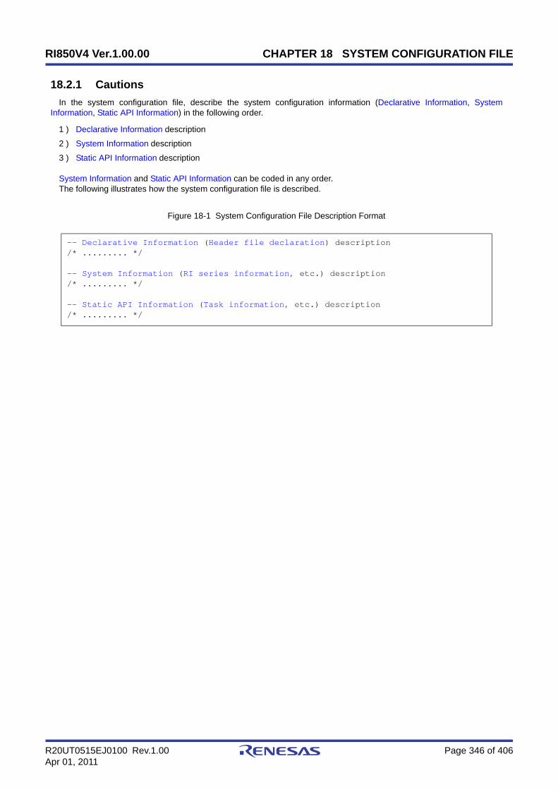
RI850V4 Ver.1.00.00 CHAPTER 18 SYSTEM CONFIGURATION FILE
R20UT0515EJ0100 Rev.1.00 Page 346 of 406Apr 01, 2011
18.2.1 Cautions
In the system configuration file, describe the system configuration information (Declarative Information, SystemInformation, Static API Information) in the following order.
1 ) Declarative Information description
2 ) System Information description
3 ) Static API Information description
System Information and Static API Information can be coded in any order.The following illustrates how the system configuration file is described.
Figure 18-1 System Configuration File Description Format
-- Declarative Information (Header file declaration) description/* ......... */
-- System Information (RI series information, etc.) description/* ......... */
-- Static API Information (Task information, etc.) description/* ......... */
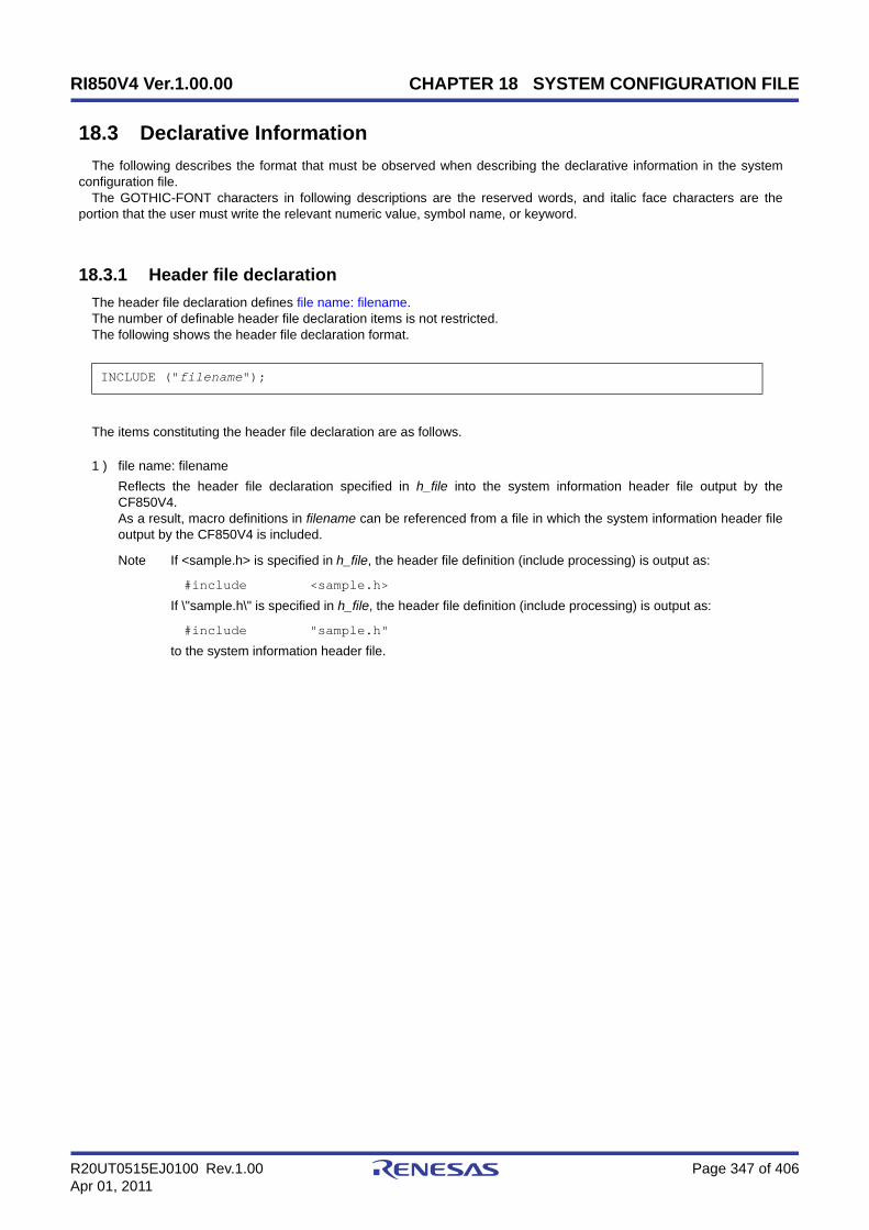
RI850V4 Ver.1.00.00 CHAPTER 18 SYSTEM CONFIGURATION FILE
R20UT0515EJ0100 Rev.1.00 Page 347 of 406Apr 01, 2011
18.3 Declarative Information
The following describes the format that must be observed when describing the declarative information in the systemconfiguration file.
The GOTHIC-FONT characters in following descriptions are the reserved words, and italic face characters are theportion that the user must write the relevant numeric value, symbol name, or keyword.
18.3.1 Header file declaration
The header file declaration defines file name: filename.The number of definable header file declaration items is not restricted.The following shows the header file declaration format.
The items constituting the header file declaration are as follows.
1 ) file name: filenameReflects the header file declaration specified in h_file into the system information header file output by theCF850V4.As a result, macro definitions in filename can be referenced from a file in which the system information header fileoutput by the CF850V4 is included.
Note If <sample.h> is specified in h_file, the header file definition (include processing) is output as:
#include <sample.h>
If \"sample.h\" is specified in h_file, the header file definition (include processing) is output as:
#include "sample.h"
to the system information header file.
INCLUDE ("filename");
RI850V4 Ver.1.00.00 CHAPTER 18 SYSTEM CONFIGURATION FILE
R20UT0515EJ0100 Rev.1.00 Page 348 of 406Apr 01, 2011
18.4 System Information
The following describes the format that must be observed when describing the system information in the systemconfiguration file.
The GOTHIC-FONT characters in following descriptions are the reserved words, and italic face characters are theportion that the user must write the relevant numeric value, symbol name, or keyword.
Items enclosed by square brackets "[ ]" can be omitted.
18.4.1 RI series information
The RI series information defines Real-time OS name: rtos_name, Version number: rtos_ver.Only one information item can be defined as RI series information.The following shows the RI series information format.
The items constituting the RI series information are as follows.
1 ) Real-time OS name: rtos_nameSpecifies the real-time OS name.The keyword that can be specified for rtos_name is the RI850V4.
2 ) Version number: rtos_verSpecifies the version number for the RI850V4.A value from V100 to V199 can be specified for rtos_ver.
RI_SERIES (rtos_name, rtos_ver);

RI850V4 Ver.1.00.00 CHAPTER 18 SYSTEM CONFIGURATION FILE
R20UT0515EJ0100 Rev.1.00 Page 349 of 406Apr 01, 2011
18.4.2 Basic information
The basic information defines Processor type: cpu, Register mode: register, Base clock interval: clkcyc, Clock timerexception code: intno, System stack size: stksz, Whether to check stack: flg, Maximum priority: maxpri, Maximum numberof interrupt handlers: maxinh, Maximum value of exception code: maxint.
Only one information item can be defined as basic information.The following shows the basic information format.
The items constituting the basic information are as follows.
1 ) Processor type: cpuSpecifies the type for a CPU.The keyword that can be specified for cpu is V850E1, V850E2, V850ES or V850E2M.
V850E1: V850E1 coreV850E2: V850E2 coreV850ES: V850ES coreV850E2M: V850E2M core
If omitted "V850E1" is specified as the target device processor type.
2 ) Register mode: registerSpecifies the register mode.The keyword that can be specified for register is r22, r26 or r32.
r22: 22-register moder26: 26-register moder32: 32-register mode
If omitted "r32" is specified as the register mode type of kernel library libri.a that is linked during systemconfiguration.
Note If -regxx is specified as the CF850V4 activation option, definition of reg_mode is ignored and theCF850V4 activation option is handled as valid information.
3 ) Base clock interval: clkcycSpecifies the base clock interval (in millisecond) of the timer to be used.A value from 0x1 to 0xffff can be specified for clkcyc.
If omitted "0x1msec" is specified as the base clock cycle of the RI850V4.
Note The base clock cycle means the occurrence interval of base clock timer interrupt tim_intno, which isrequired for implementing the TIME MANAGEMENT FUNCTIONS provided by the RI850V4. Toinitialize hardware used by the RI850V4 for time management (such as timers and controllers), thesetting must therefore be made so as to generate base clock timer interrupts at the interval defined withtim_base.
4 ) Clock timer exception code: intnoSpecifies the exception code for a clock timer.
[CA850/CX version]Only interrupt source names prescribed in the device file and 16-byte boundary values can be specified.If an interrupt source name is specified for tim_intno, the CF850V4 activation option -cpu name must bespecified.
[CPU_TYPE (cpu);][REG_MODE (register);][DEF_TIM (clkcyc);]CLK_INTNO (intno);SYS_STK (stksz);[STK_CHK (flg);][MAX_PRI (maxpri);]MAX_INT (maxinh, maxint);

RI850V4 Ver.1.00.00 CHAPTER 18 SYSTEM CONFIGURATION FILE
R20UT0515EJ0100 Rev.1.00 Page 350 of 406Apr 01, 2011
[CCV850/CCV850E version]Only 16-byte boundary values can be specified.
5 ) System stack size: stkszSpecifies the system stack size (in bytes).A value from 0x0 to 0x7ffffffc (aligned to a 4-byte boundary) can be specified for stksz.
Note 1 For expressions to calculate the system stack size, refer to "18.6 Memory Capacity Estimation".
Note 2 The memory area for system stack is secured from the ".kernel_data section".
Note 3 The stack size that is actually secured is calculated as the specified stack size plus "20 + frmsz (size ofcontext area of interrupt handler)". Refer to “Table 18-3“ about frmsz.
6 ) Whether to check stack: flgSpecifies whether to check the stack overflows before the RI850V4 starts processing.The keyword that can be specified for flg is TA_ON or TA_OFF.
TA_ON: Overflow is checkedTA_OFF: Overflow not checked
Note Overflow is not checked by default.
7 ) Maximum priority: maxpriSpecifies the maximum priority of the task.A value from 0x1 to 0x20 can be specified for maxpri.
If omitted "0x20" is specified as the maximum task priority.
8 ) Maximum number of interrupt handlers: maxinh, Maximum value of exception code: maxintSpecifies the maximum number of interrupt handlers to be registered and the maximum number of exception codespossessed by the target CPU.Only values from 0x0 to 0xff can be specified for maxinh, and values from 0x80 to 0x1060 can be specified formaxint.
Note Specify for maxinh the total number of interrupt handlers defined in Interrupt handler information.

RI850V4 Ver.1.00.00 CHAPTER 18 SYSTEM CONFIGURATION FILE
R20UT0515EJ0100 Rev.1.00 Page 351 of 406Apr 01, 2011
18.4.3 Initial FPSR register information
The initial FPSR register information defines Initial FPSR register information for the "floating-point operation setting/status register FPSR" when a processing program (e.g. task, cyclic handler, or interrupt handler) is started.
The following shows the initial FPSR register information format.
The items constituting the initial FPSR register information are as follows.
1 ) Initial FPSR register value: fpsrSpecifies the FPSR value when a processing program is started.Note that the allowable range of the fpsr setting is limited to "0x0 to 0xffffffff".Behavior is not guaranteed, however, if the value is set outside the range allowed by the hardware. See yourhardware documentation for the specific values.
If omitted The initial FPSR register value will be "0x00020000".
Caution This item is only enabled if a V850E2M device is specified. This item will be ignored if a different deviceis specified.
[ DEF_FPSR ( fpsr ); ]
RI850V4 Ver.1.00.00 CHAPTER 18 SYSTEM CONFIGURATION FILE
R20UT0515EJ0100 Rev.1.00 Page 352 of 406Apr 01, 2011
18.4.4 Memory area information
The memory area information defines Memory area name:mem_area, Memory area size:memsz for a memory area.Only values from 0x0 to 0xff can be defined as the number of memory area information items (one for each section).The following shows the memory area information format.
The items constituting the memory area information are as follows.
1 ) Memory area name:mem_areaSpecifies the name of the memory area used for management objects.Only the section-name (defined in link directive file) .mem_area from which a dot is excluded can be specified formem_area.
2 ) Memory area size:memszSpecifies the size of the memory area used for management objects (unit: bytes).Only 4-byte boundary values from 0x0 to 0x7ffffffc, or "SIZE_AUTO" can be specified for memsz.
SIZE_AUTO: Total size of management objects defined in Basic information, Task information, etc.
Note For expressions to calculate the memory area size, refer to "18.6 Memory Capacity Estimation".
MEM_AREA (mem_area, memsz);

RI850V4 Ver.1.00.00 CHAPTER 18 SYSTEM CONFIGURATION FILE
R20UT0515EJ0100 Rev.1.00 Page 353 of 406Apr 01, 2011
18.5 Static API Information
The following describes the format that must be observed when describing the static API information in the systemconfiguration file.
The GOTHIC-FONT characters in following descriptions are the reserved words, and italic face characters are theportion that the user must write the relevant numeric value, symbol name, or keyword.
Items enclosed by square brackets "[ ]" can be omitted.
18.5.1 Task information
The task information defines ID number: tskid, Attribute: tskatr, Extended information: exinf, Start address: task, Initialpriority: itskpri, Task stack size: stksz, memory area name: mem_area, Reserved for future use: stk for a task.
The number of items that can be defined as task information is limited to one for each ID number.The following shows the task information format.
The items constituting the task information are as follows.
1 ) ID number: tskidSpecifies the ID number for a task.A value from 0x1 to 0xff, or a name, can be specified for tskid.
Note When a name is specified, the CF850V4 automatically assigns an ID number.The CF850V4 outputs the relationship between a name and an ID number to the system informationheader file in the following format:
#define tskid value
2 ) Attribute: tskatrSpecifies the attribute for a task.The keyword that can be specified for tskatr is TA_HLNG, TA_ASM, TA_ACT, TA_DISPREEMPT, TA_ENAINT andTA_DISINT.
[Coding language]TA_HLNG: Start a task through a C language interface.TA_ASM: Start a task through an assembly language interface.
[Initial activation state]TA_ACT: Task is activated after the creation.
[Initial preemption state]TA_DISPREEMPT: Preemption is disabled at task activation.
[Initial interrupt state]TA_ENAINT: All interrupts are enabled at task activation.TA_DISINT: All interrupts are disabled at task activation.
Note 1 If specification of TA_ACT is omitted, the DORMANT state is specified as the initial activation state.
Note 2 If specification of TA_DISPREEMPT is omitted, the preempt acknowledge is enabled when a task movesfrom the DORMANT state to the READY state.
Note 3 If specification of TA_ENAINT and TA_DISINT is omitted, interrupts are enabled in the initial state when atask moves from the DORMANT state to the READY state.
3 ) Extended information: exinfSpecifies the extended information for a task.A value from 0x0 to 0xffffffff, or a symbol name, can be specified for exinf.
Note The target task can be manipulated by handling the extended information as if it were a functionparameter.
CRE_TSK (tskid, { tskatr, exinf, task, itskpri, stksz[:mem_area], stk });

RI850V4 Ver.1.00.00 CHAPTER 18 SYSTEM CONFIGURATION FILE
R20UT0515EJ0100 Rev.1.00 Page 354 of 406Apr 01, 2011
4 ) Start address: taskSpecifies the start address for a task.A value from 0x0 to 0xfffffffe (aligned to a 2-byte boundary), or a symbol name, can be specified for task.
5 ) Initial priority: itskpriSpecifies the initial priority for a task.A value from 0x1 to 0x20 (not greater than maxpri) can be specified for itskpri.
6 ) Task stack size: stksz, memory area name: mem_areaSpecifies the task stack size (unit: bytes) and the name of the memory area secured for the task stack.Only 4-byte boundary values from 0x0 to 0x7ffffffc can be specified for stksz, and only memory area namemem_area defined in Memory area information" can be specified for mem_area.
Note 1 For expressions to calculate the stack size, refer to "18.6 Memory Capacity Estimation".
Note 2 If specification of mem_area is omitted, the task stack is allocated to the .kernel_data section.
Note 3 The stack size that is actually secured is calculated as the specified stack size plus "20 + ctxsz (size ofcontext area of interrupt handler)". See Table 18-4 and Table 18-5 for details about ctxsz.
7 ) Reserved for future use: stkSystem-reserved area.Values that can be specified for stk are limited to NULL characters.

RI850V4 Ver.1.00.00 CHAPTER 18 SYSTEM CONFIGURATION FILE
R20UT0515EJ0100 Rev.1.00 Page 355 of 406Apr 01, 2011
18.5.2 Task exception handling routine information
The task exception handling routine information defines ID number: tskid, Attribute: texatr, Start address: texrtn for atask exception handling routine.
The number of items that can be defined as task exception handling routine information is limited to one for each IDnumber.
The following shows the task exception handling routine information format.
The items constituting the task exception handling routine information are as follows.
1 ) ID number: tskidSpecifies the ID number for a target task.A value from 0x1 to 0xff, or a task name, can be specified for tskid.
2 ) Attribute: texatrSpecifies the language used to describe a task exception handling routine.The keyword that can be specified for texatr is TA_HLNG or TA_ASM.
TA_HLNG: Start a task exception handling routine through a C language interface.TA_ASM: Start a task exception handling routine through an assembly language interface.
3 ) Start address: texrtnSpecifies the start address for a task exception handling routine.A value from 0x0 to 0xfffffffe (aligned to a 2-byte boundary), or a symbol name, can be specified for texrtn.
DEF_TEX (tskid, { texatr, texrtn });

RI850V4 Ver.1.00.00 CHAPTER 18 SYSTEM CONFIGURATION FILE
R20UT0515EJ0100 Rev.1.00 Page 356 of 406Apr 01, 2011
18.5.3 Semaphore information
The semaphore information defines ID number: semid, Attribute: sematr, Initial resource count: isemcnt, Maximumresource count: maxsem for a semaphore.
The number of items that can be defined as semaphore information is limited to one for each ID number.The following shows the semaphore information format.
The items constituting the semaphore information are as follows.
1 ) ID number: semidSpecifies the ID number for a semaphore.A value from 0x1 to 0xff, or a name, can be specified for semid.
Note When a name is specified, the CF850V4 automatically assigns an ID number.The CF850V4 outputs the relationship between a name and an ID number to the system informationheader file in the following format:
#define semid value
2 ) Attribute: sematrSpecifies the task queuing method for a semaphore.The keyword that can be specified for sematr is TA_TFIFO or TA_TPRI.
TA_TFIFO: Task wait queue is in FIFO order.TA_TPRI: Task wait queue is in task priority order.
3 ) Initial resource count: isemcntSpecifies the initial resource count for a semaphore.A value from 0x0 to 0xffff (not greater than maxsem) can be specified for isemcnt.
4 ) Maximum resource count: maxsemSpecifies the maximum resource count for a semaphore.A value from 0x1 to 0xffff can be specified for maxsem.
CRE_SEM (semid, { sematr, isemcnt, maxsem });
RI850V4 Ver.1.00.00 CHAPTER 18 SYSTEM CONFIGURATION FILE
R20UT0515EJ0100 Rev.1.00 Page 357 of 406Apr 01, 2011
18.5.4 Eventflag information
The eventflag information defines ID number: flgid, Attribute: flgatr, Initial bit pattern: iflgptn for an eventflag.The number of items that can be defined as eventflag information is limited to one for each ID number.The following shows the eventflag information format.
The items constituting the eventflag information are as follows.
1 ) ID number: flgidSpecifies the ID number for an eventflag.A value from 0x1 to 0xff, or a name, can be specified for flgid.
Note When a name is specified, the CF850V4 automatically assigns an ID number.The CF850V4 outputs the relationship between a name and an ID number to the system informationheader file in the following format:
#define flgid value
2 ) Attribute: flgatrSpecifies the attribute for an eventflag.The keyword that can be specified for flgatr is TA_TFIFO, TA_TPRI, TA_WSGL, TA_WMUL and TA_CLR.
[Task queuing method]TA_TFIFO: Task wait queue is in FIFO order.TA_TPRI: Task wait queue is in task priority order.
[Queuing count]TA_WSGL: Only one task is allowed to be in the WAITING state for the eventflag.TA_WMUL: Multiple tasks are allowed to be in the WAITING state for the eventflag.
[Bit pattern clear]TA_CLR: Bit pattern is cleared when a task is released from the WAITING state for eventflag.
Note 1 If specification of TA_TFIFO and TA_TPRI is omitted, tasks are queued in the order of bit pattern checking.
Note 2 If specification of TA_CLR is omitted, "not clear bit patterns if the required condition is satisfied" is set.
3 ) Initial bit pattern: iflgptnSpecifies the initial bit pattern for an eventflag.A value from 0x0 to 0xffffffff can be specifies for iflgptn.
CRE_FLG (flgid, { flgatr, iflgptn });
RI850V4 Ver.1.00.00 CHAPTER 18 SYSTEM CONFIGURATION FILE
R20UT0515EJ0100 Rev.1.00 Page 358 of 406Apr 01, 2011
18.5.5 Data queue information
The data queue information defines ID number: dtqid, Attribute: dtqatr, Data count: dtqcnt, memory area name:mem_area, Reserved for future use: dtq for a data queue.
The number of items that can be defined as data queue information is limited to one for each ID number.The following shows the data queue information format.
The items constituting the data queue information are as follows.
1 ) ID number: dtqidSpecifies the ID number for a data queue.A value from 0x1 to 0xff, or a name, can be specified for dtqid.
Note When a name is specified, the CF850V4 automatically assigns an ID number.The CF850V4 outputs the relationship between a name and an ID number to the system informationheader file in the following format:
#define dtqid value
2 ) Attribute: dtqatrSpecifies the task queuing method for a data queue.The keyword that can be specified for dtqatr is TA_TFIFO or TA_TPRI.
TA_TFIFO: Task wait queue is in FIFO order.TA_TPRI: Task wait queue is in task priority order.
3 ) Data count: dtqcnt, memory area name: mem_areaSpecifies the maximum number of data units that can be queued to the data queue area of a data queue, and thename of the memory area secured for the data queue area.Only values from 0x0 to 0xff can be specified for dtqcnt, and only memory area name mem_area defined inMemory area information" can be specified for mem_area.
Note If specification of mem_area is omitted, the data queue is allocated to the .kernel_data section.
4 ) Reserved for future use: dtqSystem-reserved area.Values that can be specified for dtq are limited to NULL characters.
CRE_DTQ (dtqid, { dtqatr, dtqcnt[:mem_area], dtq });

RI850V4 Ver.1.00.00 CHAPTER 18 SYSTEM CONFIGURATION FILE
R20UT0515EJ0100 Rev.1.00 Page 359 of 406Apr 01, 2011
18.5.6 Mailbox information
The mailbox information defines ID number: mbxid, Attribute: mbxatr, Maximum message priority: maxmpri, Reservedfor future use: mprihd for a mailbox.
The number of items that can be defined as mailbox information is limited to one for each ID number.The following shows the mailbox information format.
The items constituting the mailbox information are as follows.
1 ) ID number: mbxidSpecifies the ID number for a mailbox.A value from 0x1 to 0xff, or a name, can be specified for mbxid.
Note When a name is specified, the CF850V4 automatically assigns an ID number.The CF850V4 outputs the relationship between a name and an ID number to the system informationheader file in the following format:
#define mbxid value
2 ) Attribute: mbxatrSpecifies the attribute for a mailbox.The keyword that can be specified for mbxatr is TA_TFIFO, TA_TPRI, TA_MFIFO and TA_MPRI.
[Task queuing method]TA_TFIFO: Task wait queue is in FIFO order.TA_TPRI: Task wait queue is in task priority order.
[Message queuing method]TA_MFIFO: Message wait queue is in FIFO order.TA_MPRI: Message wait queue is in message priority order.
3 ) Maximum message priority: maxmpriSpecifies the maximum message priority for a mailbox.A value from 0x1 to 0x7fff can be specified for maxmpri.
Note maxmpri is valid only when TA_MPRI is specified for mqueue.It is invalid when TA_MFIFO is specified for mqueue.
4 ) Reserved for future use: mprihdSystem-reserved area.Values that can be specified for mprihd are limited to NULL characters.
CRE_MBX (mbxid, { mbxatr, maxmpri, mprihd });
RI850V4 Ver.1.00.00 CHAPTER 18 SYSTEM CONFIGURATION FILE
R20UT0515EJ0100 Rev.1.00 Page 360 of 406Apr 01, 2011
18.5.7 Mutex information
The mutex information defines ID number: mtxid, Attribute: mtxatr, Reserved for future use: ceilpri for a mutex.The number of items that can be defined as mutex information is limited to one for each ID number.The following shows the mutex information format.
The items constituting the mutex information are as follows.
1 ) ID number: mtxidSpecifies the ID number for a mutex.A value from 0x1 to 0xff, or a name, can be specified for mtxid.
Note When a name is specified, the CF850V4 automatically assigns an ID number.The CF850V4 outputs the relationship between a name and an ID number to the system informationheader file in the following format:
#define mtxid value
2 ) Attribute: mtxatrSpecifies the task queuing method for a mutex.The keyword that can be specified for mtxatr is TA_TFIFO or TA_TPRI.
TA_TFIFO: Task wait queue is in FIFO order.TA_TPRI: Task wait queue is in task priority order.
3 ) Reserved for future use: ceilpriSystem-reserved area.Only values from "0x1 to maximum task priority maxtpri defined in Basic information" can be specified for ceilpri.
CRE_MTX (mtxid, { mtxatr, ceilpri });
RI850V4 Ver.1.00.00 CHAPTER 18 SYSTEM CONFIGURATION FILE
R20UT0515EJ0100 Rev.1.00 Page 361 of 406Apr 01, 2011
18.5.8 Fixed-sized memory pool information
The fixed-sized memory pool information defines ID number: mpfid, Attribute: mpfatr, Block count: blkcnt, Basic blocksize: blksz, memory area name: mem_area, Reserved for future use: mpf for a fixed-sized memory pool.
The number of items that can be defined as fixed-sized memory pool information is limited to one for each ID number.The following shows the fixed-sized memory pool information format.
The items constituting the fixed-sized memory pool information are as follows.
1 ) ID number: mpfidSpecifies the ID number for a fixed-sized memory pool.A value from 0x1 to 0xff, or a name, can be specified for mpfid.
Note When a name is specified, the CF850V4 automatically assigns an ID number.The CF850V4 outputs the relationship between a name and an ID number to the system informationheader file in the following format:
#define mpfid value
2 ) Attribute: mpfatrSpecifies the task queuing method for a fixed-sized memory pool.The keyword that can be specified for mpfatr is TA_TFIFO or TA_TPRI.
TA_TFIFO: Task wait queue is in FIFO order.TA_TPRI: Task wait queue is in task priority order.
3 ) Block count: blkcntSpecifies the block count for a fixed-sized memory pool.A value from 0x1 to 0x7fff can be specified for blkcnt.
4 ) Basic block size: blksz, memory area name: mem_areaSpecifies the size per block (unit: bytes) and the name of the memory area secured for the fixed-size memory pool.Only 4-byte boundary values from 0x1 to 0x7ffffffc can be specified for blksz, and only memory area namesec_area defined in Memory area information" can be specified for mem_area.
Note If specification of mem_area is omitted, the fixed-sized memory pool is allocated to the .kernel_data sec-tion.
5 ) Reserved for future use: mpfSystem-reserved area.Values that can be specified for mpl are limited to NULL characters.
CRE_MPF (mpfid, { mpfatr, blkcnt, blksz[:mem_area], mpf });
RI850V4 Ver.1.00.00 CHAPTER 18 SYSTEM CONFIGURATION FILE
R20UT0515EJ0100 Rev.1.00 Page 362 of 406Apr 01, 2011
18.5.9 Variable-sized memory pool information
The variable-sized memory pool information defines ID number: mplid, Attribute: mplatr, Pool size: mplsz, memory areaname: mem_area, Reserved for future use: mpl for a variable-sized memory pool.
The number of items that can be defined as variable-sized memory pool information is limited to one for each IDnumber.
The following shows the variable-sized memory pool information format.
The items constituting the variable-sized memory pool information are as follows.
1 ) ID number: mplidSpecifies the ID number for a variable-sized memory pool.A value from 0x1 to 0xff, or a name, can be specified for mplid.
Note When a name is specified, the CF850V4 automatically assigns an ID number.The CF850V4 outputs the relationship between a name and an ID number to the system informationheader file in the following format:
#define mplid value
2 ) Attribute: mplatrSpecifies the task queuing method for a variable-sized memory pool.The keyword that can be specified for mplatr is TA_TFIFO or TA_TPRI.
TA_TFIFO: Task wait queue is in FIFO order.TA_TPRI: Task wait queue is in task priority order.
3 ) Pool size: mplsz, memory area name: mem_areaSpecifies the variable-size memory pool size (unit: bytes) and the name of the memory area secured for thevariable-size memory pool.Only 4-byte boundary values from 0x1 to 0x7ffffffc can be specified for mplsz, and only memory area namesec_area defined in Memory area information" can be specified for mem_area.
Note If specification of mem_area is omitted, the variable-sized memory pool is allocated to the .kernel_datasection.
4 ) Reserved for future use: mplSystem-reserved area.Values that can be specified for mpl are limited to NULL characters.
CRE_MPL (mplid, { mplatr, mplsz[:mem_area], mpl });

RI850V4 Ver.1.00.00 CHAPTER 18 SYSTEM CONFIGURATION FILE
R20UT0515EJ0100 Rev.1.00 Page 363 of 406Apr 01, 2011
18.5.10 Cyclic handler information
The cyclic handler information defines ID number: cycid, Attribute: cycatr, Extended information: exinf, Start address:cychdr, Activation cycle: cyctim, Activation phase: cycphs for a cyclic handler.
The number of items that can be defined as cycic handler information is limited to one for each ID number.The following shows the cyclic handler information format.
The items constituting the cyclic handler information are as follows.
1 ) ID number: cycidSpecifies the ID number for a cyclic handler.A value from 0x1 to 0xff, or a name, can be specified for cycid.
Note When a name is specified, the CF850V4 automatically assigns an ID number.The CF850V4 outputs the relationship between a name and an ID number to the system informationheader file in the following format:
#define cycid value
2 ) Attribute: cycatrSpecifies the attribute for a cyclic handler.The keywords that can be specified for cycatr are TA_HLNG, TA_ASM, TA_STA and TA_PHS.
[Coding languag]TA_HLNG: Start a cyclic handler through a C language interface.TA_ASM: Start a cyclic handler through an assembly language interface.
[Initial activation state]TA_STA: Cyclic handlers is in an operational state after the creation.
[Activation phase]TA_PHS: Cyclic handler is activated preserving the activation phase.
Note 1 If specification of TA_STA is omitted, the initial activation state is set to "non-operational state".
Note 2 If specification of TA_PHS is omitted, no activation phase items are saved.
3 ) Extended information: exinfSpecifies the extended information for a cyclic handler.A value from 0x0 to 0xffffffff, or a symbol name, can be specified for exinf.
Note The target cyclic handler can be manipulated by handling the extended information as if it were a functionparameter.
4 ) Start address: cychdrSpecifies the start address for a cyclic handler.A value from 0x0 to 0xfffffffe (aligned to a 2-byte boundary), or a symbol name, can be specified for cychdr.
5 ) Activation cycle: cyctimSpecifies the activation cycle (in millisecond) for a cyclic handler.A value from 0x1 to 0x7fffffff (aligned to ‘clkcyc’ multiple values) can be specified for cyctim.
Note If a value other than an integral multiple of the base clock cycle defined in Basic information is specified forcyctim, the CF850V4 assumes that an integral multiple is specified and performs processing.
6 ) Activation phase: cycphsSpecifies the activation phase (in millisecond) for a cyclic handler.A value from 0x1 to 0x7fffffff (aligned to ‘clkcyc’ multiple values) can be specified for cycphs.
Note 1 In the RI850V4, the initial activation phase means the relative interval from when generation of s cyclichandler is completed until the first activation request is issued.
CRE_CYC (cycid, { cycatr, exinf, cychdr, cyctim, cycphs });

RI850V4 Ver.1.00.00 CHAPTER 18 SYSTEM CONFIGURATION FILE
R20UT0515EJ0100 Rev.1.00 Page 364 of 406Apr 01, 2011
Note 2 If a value other than an integral multiple of the base clock cycle defined in Basic information is specified forcycphs, the CF850V4 assumes that an integral multiple is specified and performs processing.
RI850V4 Ver.1.00.00 CHAPTER 18 SYSTEM CONFIGURATION FILE
R20UT0515EJ0100 Rev.1.00 Page 365 of 406Apr 01, 2011
18.5.11 Interrupt handler information
The interrupt handler information defines Exception code: inhno, Attribute: inhatr, Start address: inthdr for an interrupthandler information.
The number of items that can be defined as interrupt handler information is limited to one for each exception code.The following shows the interrupt handler information format.
The items constituting the interrupt handler information are as follows.
1 ) Exception code: inhnoSpecifies the exception code for an interrupt handler.
[CA850/CX version]Only interrupt source names prescribed in the device file and 16-byte boundary values can be specified.If an interrupt source name is specified for inhno, the CF850V4 activation option -cpu name must bespecified.
[CCV850/CCV850E version]Only 16-byte boundary values can be specified.
2 ) Attribute: inhatrSpecifies the language used to describe an interrupt handler.The keyword that can be specified for inhatr is TA_HLNG or TA_ASM.
TA_HLNG: Start an interrupt handler through a C language interface.TA_ASM: Start an interrupt handler through an assembly language interface.
3 ) Start address: inthdrSpecifies the start address for an interrupt handler.A value from 0x0 to 0xfffffffe (aligned to a 2-byte boundary), or a symbol name, can be specified for inthdr.
DEF_INH (inhno, { inhatr, inthdr });

RI850V4 Ver.1.00.00 CHAPTER 18 SYSTEM CONFIGURATION FILE
R20UT0515EJ0100 Rev.1.00 Page 366 of 406Apr 01, 2011
18.5.12 CPU exception handler information
The CPU exception handler information defines Exception code: excno, Attribute: excatr, Start address: exchdr for aCPU exception handler.
The number of items that can be defined as CPU exception handler information is limited to one for each exceptioncode.
The following shows the CPU exception handler information format.
The items constituting the CPU exception handler information are as follows.
1 ) Exception code: excnoSpecifies the exception code for a CPU exception handler.
[CA850/CX version]Only interrupt source names prescribed in the device file and 16-byte boundary values can be specified.If an interrupt source name is specified for excno, the CF850V4 activation option -cpu name must bespecified.
[CCV850/CCV850E version]Only 16-byte boundary values can be specified.
Note Even when registering a CPU exception handler for exception codes that are not a 16-byte boundaryvalue like software exceptions (TRAP0n:0x4n, TRAP1n:0x5n), be sure to set a 16-byte boundary value,as shown below.
TRAP0n --> 0x40TRAP1n --> 0x50
2 ) Attribute: excatrSpecifies the language used to describe a CPU exception handler.The keyword that can be specified for excatr is TA_HLNG or TA_ASM.
TA_HLNG: Start a CPU exception handler through a C language interface.TA_ASM: Start a CPU exception handler through an assembly language interface.
3 ) Start address: exchdrSpecifies the start address for a CPU exception handler.A value from 0x0 to 0xfffffffe (aligned to a 2-byte boundary), or a symbol name, can be specified for exchdr.
DEF_EXC (excno, { excatr, exchdr });

RI850V4 Ver.1.00.00 CHAPTER 18 SYSTEM CONFIGURATION FILE
R20UT0515EJ0100 Rev.1.00 Page 367 of 406Apr 01, 2011
18.5.13 Extended service call routine information
The extended service call routine information defines Function code: fncd, Attribute: svcatr, Start address: svcrtn for anextended service call routine.
The number of items that can be defined as extended service call routine information is limited to one for each functioncode.
The following shows the extended service call routine information format.
The items constituting the extended service call routine information are as follows.
1 ) Function code: fncdSpecifies the function code for an extended service call routine.A value from 0x1 to 0xff can be specified for fncd.
2 ) Attribute: svcatrSpecifies the language used to describe an extended service call routine.The keyword that can be specified for svcatr is TA_HLNG or TA_ASM.
TA_HLNG: Start an extended service call routine through a C language interface.TA_ASM: Start an extended service call routine through an assembly language interface.
3 ) Start address: svcrtnSpecifies the start address for an extended service call routine.A value from 0x0 to 0xfffffffe (aligned to a 2-byte boundary), or a symbol name, can be specified for svcrtn.
DEF_SVC (fncd, { svcatr, svcrtn });

RI850V4 Ver.1.00.00 CHAPTER 18 SYSTEM CONFIGURATION FILE
R20UT0515EJ0100 Rev.1.00 Page 368 of 406Apr 01, 2011
18.5.14 Initialization routine information
The initialization routine information defines Attribute: iniatr, Extended information: exinf, Start address: inirtn for aninitialization routine.
The number of initialization routine information items that can be specified is defined as being within the range of 0 to254.
The following shows the idle initialization routine information format.
The items constituting the initialization routine information are as follows.
1 ) Attribute: iniatrSpecifies the language used to describe an initialization routine.The keyword that can be specified for iniatr is TA_HLNG or TA_ASM.
TA_HLNG: Start an initialization routine through a C language interface.TA_ASM: Start an initialization routine through an assembly language interface.
2 ) Extended information: exinfSpecifies the extended information for an initialization routine.A value from 0x0 to 0xffffffff, or a symbol name, can be specified for exinf.
Note The target initialization routine can be manipulated by handling the extended information as if it were afunction parameter.
3 ) Start address: inirtnSpecifies the start address for an initialization routine.A value from 0x0 to 0xfffffffe (aligned to a 2-byte boundary), or a symbol name, can be specified for inirtn.
ATT_INI ({ initatr, exinf, inirtn });

RI850V4 Ver.1.00.00 CHAPTER 18 SYSTEM CONFIGURATION FILE
R20UT0515EJ0100 Rev.1.00 Page 369 of 406Apr 01, 2011
18.5.15 Idle routine information
The idle routine information defines Attribute: idlatr, Start address: idlrtn for an idle routine.The number of idle routine information items that can be specified is defined as being within the range of 0 to 1.The following shows the idle routine information format.
The items constituting the idle routine information are as follows.
1 ) Attribute: idlatrSpecifies the language used to describe an idle routine.The keyword that can be specified for idlatr is TA_HLNG or TA_ASM.
TA_HLNG: Start an idle routine through a C language interface.TA_ASM: Start an idle routine through an assembly language interface.
2 ) Start address: idlrtnSpecifies the start address for an idle routine.A value from 0x0 to 0xfffffffe (aligned to a 2-byte boundary), or a symbol name, can be specified for idlrtn.
VATT_IDL ({ idlatr, idlrtn });

RI850V4 Ver.1.00.00 CHAPTER 18 SYSTEM CONFIGURATION FILE
R20UT0515EJ0100 Rev.1.00 Page 370 of 406Apr 01, 2011
18.6 Memory Capacity Estimation
Memory areas used and managed by the RI850V4 are broadly classified into five types of sections.
18.6.1 .kernel_const section
This is the area to which management objects (such as a system management table and task management blocks)required for the RI850V4 operation and for realizing functions provided by the RI850V4 are allocated.
The following shows the size calculation method for the data to be assigned to the .kernel_const section (unit: bytes).
Table 18-1 .kernel_const Section Size Calculation Method
Note Each keyword in the size calculation methods has the following meaning.
maxtpri: Priority range specified in Basic informationmaxintno: Exception code range specified in Basic information
This also means the maximum exception code possessed by the target device if the useddevice is specified via PM+ or by using the -cpu option with the CF850V4 executed from thecommand line.
maxbtsk: Total number of Task informationmaxtex: Total number of Task exception handling routine informationmaxsem: Total number of Semaphore informationmaxflg: Total number of Eventflag informationmaxdtq: Total number of Data queue informationmaxmbx: Total number of Mailbox informationmaxmtx: Total number of Mutex informationmaxmpf: Total number of Fixed-sized memory pool informationmaxmpl: Total number of Variable-sized memory pool informationmaxcyc: Total number of Cyclic handler information
Object Name Size Calculation Method (in bytes)
System base table
V850E1/V850E2/V850ESCA850/CX version : 72CCV850/CCV850E version : 76
V850E2MCA850/CX version : 76CCV850/CCV850E version : 80
Ready queue align4 (maxtpri)
Interrupt mask control table align4 (align16 ((maxintno / 16) - 7) / 8)
Task control block 8 * maxbtsk
Task exception handling routine control block 8 * maxtex
Semaphore control block 8 * maxsem
Eventflag control block 8 * maxflg
Data Queue control block 8 * maxdtq
Mailbox control block 12 * maxmbx
Mutex control block 8 * maxmtx
Fixed-sized memory pool control block 8 * maxmpf
Variable-sized memory pool control block 8 * maxmpl
Cyclic handler control block 8 * maxcyc

RI850V4 Ver.1.00.00 CHAPTER 18 SYSTEM CONFIGURATION FILE
R20UT0515EJ0100 Rev.1.00 Page 371 of 406Apr 01, 2011
18.6.2 .kernel_info section
This is the area to which data related to OS resources (such as base clock cycle and maximum task priority) required forthe RI850V4 operation and for realizing functions provided by the RI850V4 are allocated.
The following shows the size calculation method for the management objects to be assigned to the .kernel_info section(unit: bytes).
Table 18-2 .kernel_info Section Size Calculation Method
Note Each keyword in the size calculation methods has the following meaning.
maxact: Total amount of defined Task information (initial activation state: TA_ACT)maxsta: Total amount of defined Cyclic handler information (initial activation state: TA_STA)maxintno: Exception code range specified in Basic information
This also means the maximum exception code possessed by the target device if the useddevice is specified via PM+ or by using the -cpu option with the CF850V4 executed from thecommand line.
maxtsk: Total number of Task informationmaxsem: Total number of Semaphore informationmaxflg: Total number of Eventflag informationmaxdtq: Total number of Data queue informationmaxmbx: Total number of Mailbox informationmaxmtx: Total number of Mutex informationmaxmpf: Total number of Fixed-sized memory pool information
Object Name Size Calculation Method (in bytes)
System information table
V850E1/V850E2/V850ESCA850/CX version: 208CCV850/CCV850E version : 212
V850E2MCA850/CX version: 212CCV850/CCV850E version : 216
Activation task ID table align4 (maxact)
Activation cyclic handler ID table align4 (maxsta)
Interrupt mask information table align4 (align16 ((maxintno / 16) - 7) / 8)
Task information block 24 * maxtsk
Semaphore information block 8 * maxsem
Eventflag information block 8 * maxflg
Data queue information block 8 * maxdtq
Mailbox information block 4 * maxmbx
Mutex information block align4 (2 * maxmtx)
Fixed-sized memory pool information block 12 * maxmpf
Variable-sized memory pool information block 12 * maxmpl
Cyclic handler information block 20 * maxcyc
Extended service call routine information block 8 * maxsvc
Interrupt handler information block 8 * maxint
Interrupt handler ID table align4 ((maxintno / 16) + 1)
Initialization routine information block 12 * maxini
Idle routine information block 8
Memory area information block 8 * maxmem

RI850V4 Ver.1.00.00 CHAPTER 18 SYSTEM CONFIGURATION FILE
R20UT0515EJ0100 Rev.1.00 Page 372 of 406Apr 01, 2011
maxmpl: Total number of Variable-sized memory pool informationmaxcyc: Total number of Cyclic handler informationmaxsvc: Total number of Extended service call routine informationmaxint: Total number of Initialization routine informationmaxini: Total number of Initialization routine informationmaxmem: Total number of Memory area information
18.6.3 .kernel_data section/user-defined section
.kernel_data and user-defined sections are areas to which the memory area managed by the RI850V4 is allocated.These sections are available to processing programs. Generally, all memory is allocated to the .kernel_data section, butthe user-defined section can be used if you want to split up this area. Define the user-defined section using "memory-areainformation" during configuration.
The memory that can be allocated to each section differs, as shown below.
The .kernel_data section and user-defined section are divided into areas used by the suer, and RI850V4 managementareas for managing them. The sizes of the .kernel_data section/user-defined section are calculated as shown below.
Size of .kernel_data section = RI_SZ (.kernel_data section) + USR_SZ (.kernel_data section)
Size of user-defined section = RI_SZ (user-defined section) + USR_SZ (user-defined section)
- RI_SZ (.kernel_data section/user-defined section)This is the size of the RI850V4 managed area in the .kernel_data section/user-defined section. It is calculated asshown below.
RI_SZ = 20 + frmsz
tsknum + Σctxsz k
k = 1
+ 4 * mplnum
Note The expression “20 + frmsz“ in the formula above is required for the .kernel_data section, and not requiredfor the user-defined section.
frmsz: Context area where interrupt handler execution information is stored.The value varies depending on the attribute, processor type, and register mode.See Table 18-3.
ctxtsz: Context area where task execution information is stored.The value varies depending on the attribute, processor type, and register mode.See Table 18-4 and Table 18-5.
tsknum: Total number of task defined in task information.
mplnum: Number of variable-sized memory pool defined in variable-sized memory pool information.
.kernel_data Section User-defined Section
System stackTask stackData queue areaFixed-sized memory poolVariable-sized memory pool
Task stackData queue areaFixed-sized memory poolVariable-sized memory pool

RI850V4 Ver.1.00.00 CHAPTER 18 SYSTEM CONFIGURATION FILE
R20UT0515EJ0100 Rev.1.00 Page 373 of 406Apr 01, 2011
Table 18-3 Context Area of Interrupt Handler (frmsz)
Table 18-4 Context Area of a Task (Preempt Acknowledge Status: non TA_DISPREEMPT) (ctxsz)
Table 18-5 Context Area of a Task (Preempt Acknowledge Status: TA_DISPREEMPT) (ctxsz)
- USR_SZ (.kernel_data section/user-defined section)This is the size of the area used by the user in the .kernel_data section/user-defined section. It is calculated as shownbelow.
USR_SZ = align4 (sys_stksz)
tsknum + Σalign4 (stksz)k
k = 1
dtqnum + Σ (dtqcnt * 4)k
k = 1
mpfnum + Σ (align4 (blksz)k * blkcnt)k
k = 1
mplnum + Σ align4 (mplsz)k
k = 1
Register ModeV850E1/V850E2/V850ES V850E2M
CA850/CX CCV850/CCV850E CA850/CX CCV850/CCV850E
22-register mode 60 64 68 72
26-register mode 68 72 76 80
32-register mode 80 84 88 92
Register ModeV850E1/V850E2/V850ES V850E2M
CA850/CX CCV850/CCV850E CA850/CX CCV850/CCV850E
22-register mode 88 92 100 104
26-register mode 104 108 116 120
32-register mode 128 132 140 144
Register ModeV850E1/V850E2/V850ES V850E2M
CA850/CX CCV850/CCV850E CA850/CX CCV850/CCV850E
22-register mode 60 64 68 72
26-register mode 68 72 76 80
32-register mode 80 84 88 92

RI850V4 Ver.1.00.00 CHAPTER 18 SYSTEM CONFIGURATION FILE
R20UT0515EJ0100 Rev.1.00 Page 374 of 406Apr 01, 2011
Note The expression “align4 (sys_stksz)“ in the formula above is required for the .kernel_data section, and notrequired for the user-defined section.
sys_stksz: System stack size defined in basic information.
tsknum: Total number of task defined in task information.
stksz: Stack size of task defined in task information.
dtqnum: Total number of data defined in data queue information.
dtqcnt: Amount of data defined in data queue information.
mpfnum: Number of fixed-sized memory pool defined in fixed-sized memory pool information.
blksz: Block unit size defined in fixed-sized memory pool information.
blkcnt: Total number of memory blocks defined in fixed-sized memory pool information.
mplnum: Number of variable-sized memory pool defined in variable-sized memory pool information.
mplsz: Size of pool defined in variable-sized memory pool information.
The values plugged into this expression are to be estimated by the user in accordance with the application.The only exception to this is the estimation of sys_stksz, which is calculated as shown below based on the applicationinformation.We recommend setting a size somewhat larger than the size calculated here, for leeway.
Set sys_stksz to the largest of sys_stksz1, sys_stksz2, and sys_stksz3, below.
tskprinumsys_stksz1 = Σ (ctxsz)k
k = 1
intprinum + Σ (align4 (intsz_hi) + frmsz)k
k = 1
sys_stksz2 = idlsz
sys_stksz3 = inisz_hi
tskprinum: Total number of task priorities defined in basic information.
ctxtsz: Context area where task execution information is stored.The value varies depending on the attribute, processor type, and register mode.See Table 18-4 and Table 18-5.
intprinum: Total number of interrupt priorities that the device has.
intsz_hi: Largest task stack size of interrupt handlers/cyclic handlers for task priority k.A cyclic handler of interrupt priority k is the interrupt priority of the basic-clock timer interrupt defined inthe basic information.If there are no interrupt handlers/cyclic handlersin interrupt priority k, no calculation for interruptpriority k is required.
frmsz: Context area where interrupt handler execution information is stored.The value varies depending on the attribute, processor type, and register mode.See Table 18-3.
idlsz: Stack size used by the idle routine.
inisz_hi: Largest stack size in the initialization routine.
RI850V4 Ver.1.00.00 CHAPTER 18 SYSTEM CONFIGURATION FILE
R20UT0515EJ0100 Rev.1.00 Page 375 of 406Apr 01, 2011
18.6.4 .kernel_system section
This is the area to which the RI850V4 main processing (kernel common module, kernel module) is allocated.The following lists the memory areas to be allocated to the .kernel_system section.
- Kernel common moduleA core processing module of RI850V4, which provides the following functions.
‐SCHEDULER
‐SYSTEM INITIALIZATION ROUTINE (Kernel Initialization Module)
The kernel common module occupies a memory area of approximately 4 KB.
- Kernel moduleA processing module of service calls provided by the RI850V4, which provides the following functions.
‐TASK MANAGEMENT FUNCTIONS
‐TASK DEPENDENT SYNCHRONIZATION FUNCTIONS‐TASK EXCEPTION HANDLING FUNCTIONS‐SYNCHRONIZATION AND COMMUNICATION FUNCTIONS (Semaphores, Eventflags, Data Queues,
Mailboxes)‐EXTENDED SYNCHRONIZATION AND COMMUNICATION FUNCTIONS (Mutexes)‐MEMORY POOL MANAGEMENT FUNCTIONS (Fixed-Sized Memory Pools, Variable-Sized Memory Pools)‐TIME MANAGEMENT FUNCTIONS‐SYSTEM STATE MANAGEMENT FUNCTIONS‐INTERRUPT MANAGEMENT FUNCTIONS‐SERVICE CALL MANAGEMENT FUNCTIONS‐SYSTEM CONFIGURATION MANAGEMENT FUNCTIONS
The kernel module occupies a memory area of approximately 1 KB to 21 KB, but the required memory capacity canbe reduced by setting restrictions on the type of service calls used in the system.
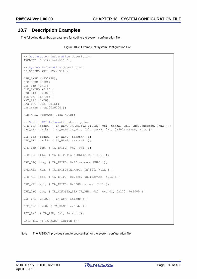
RI850V4 Ver.1.00.00 CHAPTER 18 SYSTEM CONFIGURATION FILE
R20UT0515EJ0100 Rev.1.00 Page 376 of 406Apr 01, 2011
18.7 Description Examples
The following describes an example for coding the system configuration file.
Figure 18-2 Example of System Configuration File
Note The RI850V4 provides sample source files for the system configuration file.
-- Declarative Information descriptionINCLUDE (" \"kernel.h\" ");
-- System Information descriptionRI_SERIES (RI850V4, V100);
CPU_TYPE (V850E2M);REG_MODE (r32);DEF_TIM (0x1);CLK_INTNO (0x80);SYS_STK (0x1000);STK_CHK (TA_OFF);MAX_PRI (0x20);MAX_INT (0x2, 0x1e);DEF_FPSR ( 0x00020000 );
MEM_AREA (usrmem, SIZE_AUTO);
-- Static API Information descriptionCRE_TSK (taskA, { TA_HLNG|TA_ACT|TA_DISINT, 0x1, taskA, 0x1, 0x800:usrmem, NULL });CRE_TSK (taskB, { TA_HLNG|TA_ACT, 0x2, taskB, 0x1, 0x800:usrmem, NULL });
DEF_TEX (taskA, { TA_HLNG, texrtnA });DEF_TEX (taskB, { TA_HLNG, texrtnB });
CRE_SEM (sem, { TA_TFIFO, 0x0, 0x1 });
CRE_FLG (flg, { TA_TFIFO|TA_WSGL|TA_CLR, 0x0 });
CRE_DTQ (dtq, { TA_TFIFO, 0xff:usrmem, NULL });
CRE_MBX (mbx, { TA_TFIFO|TA_MPRI, 0x7fff, NULL });
CRE_MPF (mpf, { TA_TFIFO, 0x7fff, 0x1:usrmem, NULL });
CRE_MPL (mpl, { TA_TFIFO, 0x8000:usrmem, NULL });
CRE_CYC (cyc, { TA_HLNG|TA_STA|TA_PHS, 0x1, cychdr, 0x100, 0x1000 });
DEF_INH (0x1c0, { TA_ASM, inthdr });
DEF_EXC (0x60, { TA_HLNG, exchdr });
ATT_INI ({ TA_ASM, 0x1, inirtn });
VATT_IDL ({ TA_HLNG, idlrtn });

RI850V4 Ver.1.00.00 CHAPTER 19 CONFIGURATOR CF850V4
R20UT0515EJ0100 Rev.1.00 Page 377 of 406Apr 01, 2011
CHAPTER 19 CONFIGURATOR CF850V4
This chapter explains configurator CF850V4, which is provided by the RI850V4 as a utility tool useful for systemconstruction.
19.1 Outline
To build systems (load module) that use functions provided by the RI850V4, the information storing data to be providedfor the RI850V4 is required.
Since information files are basically enumerations of data, it is possible to describe them with various editors.Information files, however, do not excel in descriptiveness and readability; therefore substantial time and effort are
required when they are described.To solve this problem, the RI850V4 provides a utility tool (configurator "CF850V4") that converts a system configuration
file which excels in descriptiveness and readability into information files.The CF850V4 reads the system configuration file as a input file, and then outputs information files.The information files output from the CF850V4 are explained below.
- System information table fileAn information file that contains data related to OS resources (base clock interval, maximum priority, managementobject, or the like) required by the RI850V4 to operate.
- System information header fileAn information file that contains the correspondence between object names (task names, semaphore names, or thelike) described in the system configuration file and IDs.
- Entry fileA routine (Interrupt entry processing, CPU exception entry processing) dedicated to entry processing that holdsprocessing to branch to relevant processing (such as interrupt preprocessing or CPU exception preprocessing), forthe handler address to which the CPU forcibly passes the control when an interrupt or CPU exception occurs.

RI850V4 Ver.1.00.00 CHAPTER 19 CONFIGURATOR CF850V4
R20UT0515EJ0100 Rev.1.00 Page 378 of 406Apr 01, 2011
19.2 Activation Method
19.2.1 Activating from command line
The following is how to activate the CF850V4 from the command line.Note that, in the examples below, "C>" indicates the command prompt, "D" indicates pressing of the space key, and
"<Enter>" indicates pressing of the enter key.The activation options enclosed in "[ ]" can be omitted.
[CA850/CX version]
[CCV850/CCV850E version]
The details of each activation option are explained below:
- @cmd_fileSpecifies the command file name to be input.
If omitted The activation options specified on the command line is valid.
Note For details about the command file, refer to "19.2.3 Command file".
- -cpu nameSpecifies type specification names of target device.
If omitted The processor type specified with Basic information is valid.If this activation option is not specified, the CF850V4 does not load the device file. As a result, definitionsusing interrupt source names defined in the device file can no longer be used in the system configurationfile.
- -devpath=pathRetrieves the device file corresponding to the target device specified with -cpu name from the path folder.
If omitted The device file is retrieved for the current folder.
- -regxxSpecifies the output file format (register mode).The keyword that can be specified for xx is 22, 26 or 32.
22: 22-register mode26: 26-register mode32: 32-register mode
If omitted The register mode specified with RI series information is valid. If either this activation option or the register mode specification in RI series information is not specified,The CF850V4 assumes "-reg32" to be specified as the register mode.
- -isitfileSpecify the output file name (system information table file name) while the CF850V4 is activated.
If omitted The CF850V4 assumes that the following activation option is specified, and performs processing.
C> cf850v4.exe [@cmd_file] [-cpu name] [-devpath=path] [-regxx] [-i sitfile] [-d includefile] [-e entry] [-ni] [-nd] [-ne] [-t tool] [-T compiler_path] [-I include_path] [-np] [-V] [-help]file <Enter>
C> cf850v4.exe [@cmd_file] [-cpu name] [-devpath=path] [-regxx] [-i sitfile] [-d includefile] [-e entry] [-ni] [-nd] [-ne] [-t tool] [-T compiler_path] [-I include_path] [-np] [-V] [-help]file <Enter>

RI850V4 Ver.1.00.00 CHAPTER 19 CONFIGURATOR CF850V4
R20UT0515EJ0100 Rev.1.00 Page 379 of 406Apr 01, 2011
CA850/CX version : -i sit.sCCV850/CCV850E version : -i sit.850
Note 1 Specify the output file name sitfile within 255 characters including the path name.
Note 2 If this activation option is specified together with -ni, the CF850V4 handles -ni as the valid option.
- -d includefileSpecify the output file name (system information header file name) while the CF850V4 is activated.
If omitted If omitted The CF850V4 assumes that -d kernel_id.h is specified and performs processing.
Note 1 Specify the output file name includefile within 255 characters including the path name.
Note 2 If this activation option is specified together with -nd, the CF850V4 handles -nd as the valid option.
- -eentrySpecify the output file name (entry file name) while the CF850V4 is activated.
If omitted The CF850V4 assumes that the following activation option is specified, and performs processing.
CA850/CX version : -e entry.sCCV850/CCV850E version : -e entry.850
Note 1 Specify the output file name entry within 255 characters including the path name.
Note 2 If this activation option is specified together with -ne, the CF850V4 handles -ne as the valid option.
- -niDisables output of the system information table file.
If omitted The CF850V4 assumes that the following activation option is specified, and performs processing.
CA850/CX version : -i sit.sCCV850/CCV850E version : -i sit.850
Note If this activation option is specified together with -i sitfile, the CF850V4 handles this activation option asthe valid option.
- -ndDisables output of the system information header file.
If omitted If omitted The CF850V4 assumes that -d kernel_id is specified and performs processing.
Note If this activation option is specified together with -d includefile, the CF850V4 handles this activationoption as the valid option.
- -neDisables output of the entry file.
If omitted The CF850V4 assumes that the following activation option is specified, and performs processing.
CA850/CX version : -e entry.sCCV850/CCV850E version : -e entry.850
Note If this activation option is specified together with -e entry, the CF850V4 handles this activation option asthe valid option.
- -t toolSpecifies the type of the C compiler package used.Only REL and GHS can be specified for tool as the keyword.
REL: CA850/CXGHS: CCV850/CCV850E
If omitted The CF850V4 assumes that -t REL is specified and performs processing.
- -Tcompiler_pathSpecifies the command search path for the C preprocessor of the C compiler package specified by -t tool.
RI850V4 Ver.1.00.00 CHAPTER 19 CONFIGURATOR CF850V4
R20UT0515EJ0100 Rev.1.00 Page 380 of 406Apr 01, 2011
If omitted The CF850V4 searches commands from a folder specified by environment variable (such as PATH).
Note Specify the command search path name compiler_path within 255 characters.
- -I include_pathSpecifies the folder name for searching Header file declaration described in input file file.
If omitted The CF850V4 starts searching from a folder where the input file specified by file is stored, the currentfolder, default search target folder of the C compiler package specified by -t tool in that order.
Note Specify the include path name include_path within 255 characters.
- -npDisables C preprocessor activation when the CF850V4 finished the analysis for syntax included in the systemconfiguration file.
If omitted The CF850V4 activates the C preprocessor of the C compiler package specified by -t tool.
- -VOutputs version information for the CF850V4 to the standard output.
Note If this activation option is specified, the CF850V4 handles other activation options as invalid options andsuppresses outputting of information files.
- -helpOutputs the usage of the activation options for the CF850V4 to the standard output.
Note If this activation option is specified, the CF850V4 handles other activation options as invalid options andsuppresses outputting of information files.
- fileSpecifies the system configuration file name to be input.
Note 1 Specify the input file name file within 255 characters including the path name.
Note 2 This input file name can be omitted only when -V or -help is specified.
19.2.2 Activating from CubeSuite+
This is started when CubeSuite+ performs a build, in accordance with the setting on the Property panel, on the [SystemConfiguration File Related Information] tab.
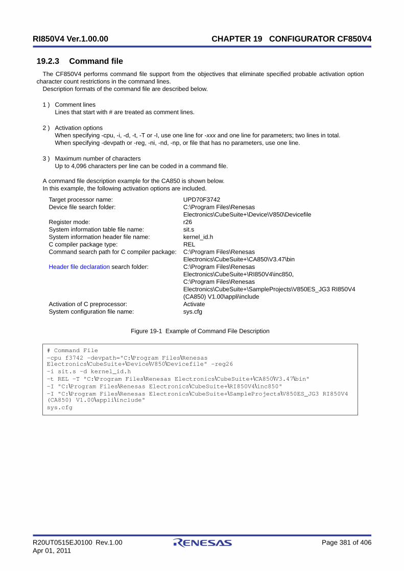
RI850V4 Ver.1.00.00 CHAPTER 19 CONFIGURATOR CF850V4
R20UT0515EJ0100 Rev.1.00 Page 381 of 406Apr 01, 2011
19.2.3 Command file
The CF850V4 performs command file support from the objectives that eliminate specified probable activation optioncharacter count restrictions in the command lines.
Description formats of the command file are described below.
1 ) Comment linesLines that start with # are treated as comment lines.
2 ) Activation optionsWhen specifying -cpu, -i, -d, -t, -T or -I, use one line for -xxx and one line for parameters; two lines in total.When specifying -devpath or -reg, -ni, -nd, -np, or file that has no parameters, use one line.
3 ) Maximum number of charactersUp to 4,096 characters per line can be coded in a command file.
A command file description example for the CA850 is shown below.In this example, the following activation options are included.
Target processor name: UPD70F3742Device file search folder: C:\Program Files\Renesas
Electronics\CubeSuite+\Device\V850\DevicefileRegister mode: r26System information table file name: sit.sSystem information header file name: kernel_id.hC compiler package type: RELCommand search path for C compiler package: C:\Program Files\Renesas
Electronics\CubeSuite+\CA850\V3.47\binHeader file declaration search folder: C:\Program Files\Renesas
Electronics\CubeSuite+\RI850V4\inc850, C:\Program Files\Renesas Electronics\CubeSuite+\SampleProjects\V850ES_JG3 RI850V4 (CA850) V1.00\appli\include
Activation of C preprocessor: ActivateSystem configuration file name: sys.cfg
Figure 19-1 Example of Command File Description
# Command File-cpu f3742 -devpath="C:\Program Files\Renesas Electronics\CubeSuite+\Device\V850\Devicefile" -reg26-i sit.s -d kernel_id.h-t REL -T "C:\Program Files\Renesas Electronics\CubeSuite+\CA850\V3.47\bin"-I "C:\Program Files\Renesas Electronics\CubeSuite+\RI850V4\inc850"-I "C:\Program Files\Renesas Electronics\CubeSuite+\SampleProjects\V850ES_JG3 RI850V4 (CA850) V1.00\appli\include"sys.cfg
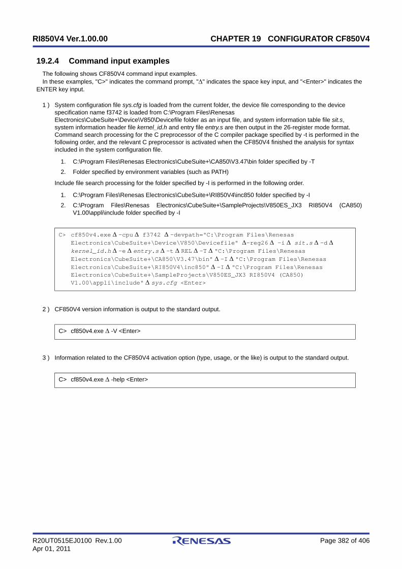
RI850V4 Ver.1.00.00 CHAPTER 19 CONFIGURATOR CF850V4
R20UT0515EJ0100 Rev.1.00 Page 382 of 406Apr 01, 2011
19.2.4 Command input examples
The following shows CF850V4 command input examples.In these examples, "C>" indicates the command prompt, "" indicates the space key input, and "<Enter>" indicates the
ENTER key input.
1 ) System configuration file sys.cfg is loaded from the current folder, the device file corresponding to the device specification name f3742 is loaded from C:\Program Files\Renesas Electronics\CubeSuite+\Device\V850\Devicefile folder as an input file, and system information table file sit.s, system information header file kernel_id.h and entry file entry.s are then output in the 26-register mode format.Command search processing for the C preprocessor of the C compiler package specified by -t is performed in the following order, and the relevant C preprocessor is activated when the CF850V4 finished the analysis for syntax included in the system configuration file.
1. C:\Program Files\Renesas Electronics\CubeSuite+\CA850\V3.47\bin folder specified by -T
2. Folder specified by environment variables (such as PATH)
Include file search processing for the folder specified by -I is performed in the following order.
1. C:\Program Files\Renesas Electronics\CubeSuite+\RI850V4\inc850 folder specified by -I
2. C:\Program Files\Renesas Electronics\CubeSuite+\SampleProjects\V850ES_JX3 RI850V4 (CA850)V1.00\appli\include folder specified by -I
2 ) CF850V4 version information is output to the standard output.
3 ) Information related to the CF850V4 activation option (type, usage, or the like) is output to the standard output.
C> cf850v4.exe-cpu f3742 -devpath="C:\Program Files\Renesas Electronics\CubeSuite+\Device\V850\Devicefile" -reg26 -i sit.s-d kernel_id.h-eentry.s-tREL-T"C:\Program Files\Renesas Electronics\CubeSuite+\CA850\V3.47\bin"-I"C:\Program Files\Renesas Electronics\CubeSuite+\RI850V4\inc850"-I"C:\Program Files\Renesas Electronics\CubeSuite+\SampleProjects\V850ES_JX3 RI850V4 (CA850) V1.00\appli\include"sys.cfg <Enter>
C> cf850v4.exe -V <Enter>
C> cf850v4.exe -help <Enter>

RI850V4 Ver.1.00.00 APPENDIX A WINDOW REFERENCE
R20UT0515EJ0100 Rev.1.00 Page 383 of 406Apr 01, 2011
APPENDIX A WINDOW REFERENCE
This appendix explains the window/panels that are used when the activation option for the CF850V4 is specified fromthe integrated development environment platform CubeSuite+.
A.1 Description
The following shows the list of window/panels.
Table A-1 List of Window/Panels
Window/Panel Name Function Description
Main window This is the first window to be open when CubeSuite+ is launched.
Project Tree panel This panel is used to display the project components in tree view.
Property panelThis panel is used to display the detailed information on the Realtime OSnode, system configuration file, or the like that is selected on the ProjectTree panel and change the settings of the information.
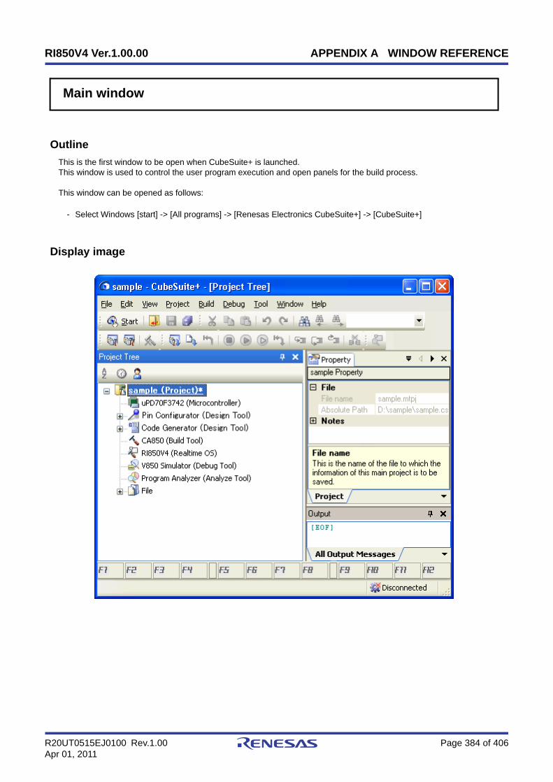
RI850V4 Ver.1.00.00 APPENDIX A WINDOW REFERENCE
R20UT0515EJ0100 Rev.1.00 Page 384 of 406Apr 01, 2011
Main window
Outline
This is the first window to be open when CubeSuite+ is launched.This window is used to control the user program execution and open panels for the build process.
This window can be opened as follows:
- Select Windows [start] -> [All programs] -> [Renesas Electronics CubeSuite+] -> [CubeSuite+]
Display image

RI850V4 Ver.1.00.00 APPENDIX A WINDOW REFERENCE
R20UT0515EJ0100 Rev.1.00 Page 385 of 406Apr 01, 2011
Explanation of each area
1 ) Menu barDisplays the menus relate to realtime OS.Contents of each menu can be customized in the User Setting dialog box.
- [View]
2 ) ToolbarDisplays the buttons relate to realtime OS.Buttons on the toolbar can be customized in the User Setting dialog box. You can also create a new toolbar in thesame dialog box.
- Realtime OS toolbar
3 ) Panel display areaThe following panels are displayed in this area.
- Project Tree panel
- Property panel
- Output panel
See the each panel section for details of the contents of the display.
Note See CubeSuite+ V850 Build / CubeSuite+ Build for CX Compiler User's Manual for details about theOutput panel.
Realtime OS The [View] menu shows the cascading menu to start the tools of realtimeOS.
Resource Information Opens the Realtime OS Resource Information panel.Note that this menu is disabled when the debug tool is not connected.
Performance Analyzer Opens the AZ850V4 window.Note that this menu is disabled when the debug tool is not connected.
Opens the Realtime OS Resource Information panel.Note that this button is disabled when the debug tool is not connected.
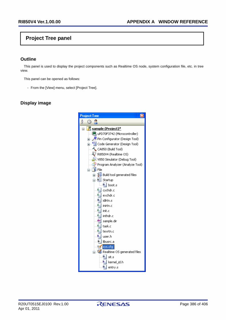
RI850V4 Ver.1.00.00 APPENDIX A WINDOW REFERENCE
R20UT0515EJ0100 Rev.1.00 Page 386 of 406Apr 01, 2011
Project Tree panel
Outline
This panel is used to display the project components such as Realtime OS node, system configuration file, etc. in treeview.
This panel can be opened as follows:
- From the [View] menu, select [Project Tree].
Display image
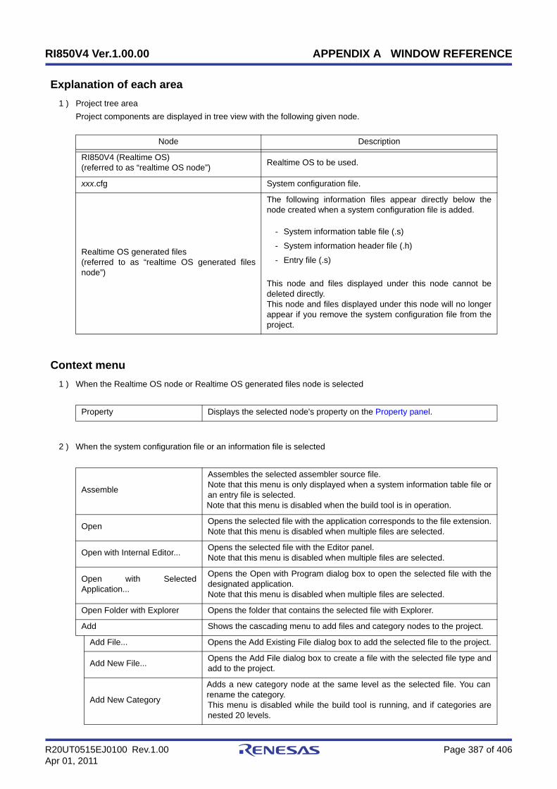
RI850V4 Ver.1.00.00 APPENDIX A WINDOW REFERENCE
R20UT0515EJ0100 Rev.1.00 Page 387 of 406Apr 01, 2011
Explanation of each area
1 ) Project tree areaProject components are displayed in tree view with the following given node.
Context menu
1 ) When the Realtime OS node or Realtime OS generated files node is selected
2 ) When the system configuration file or an information file is selected
Node Description
RI850V4 (Realtime OS)(referred to as “realtime OS node”) Realtime OS to be used.
xxx.cfg System configuration file.
Realtime OS generated files(referred to as “realtime OS generated filesnode”)
The following information files appear directly below thenode created when a system configuration file is added.
- System information table file (.s)
- System information header file (.h)
- Entry file (.s)
This node and files displayed under this node cannot bedeleted directly.This node and files displayed under this node will no longerappear if you remove the system configuration file from theproject.
Property Displays the selected node's property on the Property panel.
Assemble
Assembles the selected assembler source file.Note that this menu is only displayed when a system information table file oran entry file is selected.Note that this menu is disabled when the build tool is in operation.
Open Opens the selected file with the application corresponds to the file extension.Note that this menu is disabled when multiple files are selected.
Open with Internal Editor... Opens the selected file with the Editor panel.Note that this menu is disabled when multiple files are selected.
Open with SelectedApplication...
Opens the Open with Program dialog box to open the selected file with thedesignated application.Note that this menu is disabled when multiple files are selected.
Open Folder with Explorer Opens the folder that contains the selected file with Explorer.
Add Shows the cascading menu to add files and category nodes to the project.
Add File... Opens the Add Existing File dialog box to add the selected file to the project.
Add New File... Opens the Add File dialog box to create a file with the selected file type andadd to the project.
Add New Category
Adds a new category node at the same level as the selected file. You canrename the category.This menu is disabled while the build tool is running, and if categories arenested 20 levels.
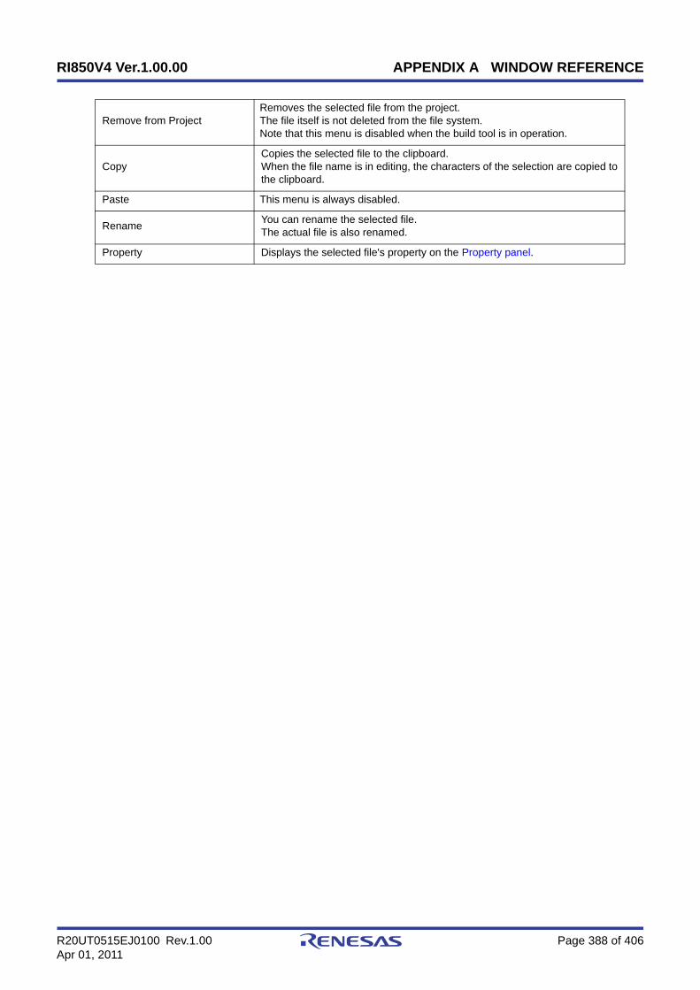
RI850V4 Ver.1.00.00 APPENDIX A WINDOW REFERENCE
R20UT0515EJ0100 Rev.1.00 Page 388 of 406Apr 01, 2011
Remove from ProjectRemoves the selected file from the project.The file itself is not deleted from the file system.Note that this menu is disabled when the build tool is in operation.
CopyCopies the selected file to the clipboard.When the file name is in editing, the characters of the selection are copied tothe clipboard.
Paste This menu is always disabled.
Rename You can rename the selected file.The actual file is also renamed.
Property Displays the selected file's property on the Property panel.

RI850V4 Ver.1.00.00 APPENDIX A WINDOW REFERENCE
R20UT0515EJ0100 Rev.1.00 Page 389 of 406Apr 01, 2011
Property panel
Outline
This panel is used to display the detailed information on the Realtime OS node, system configuration file, or the like thatis selected on the Project Tree panel by every category and change the settings of the information.
This panel can be opened as follows:
- On the Project Tree panel, select the Realtime OS node, system configuration file, or the like, and then select the[View] menu -> [Property] or the [Property] from the context menu.
Note When either one of the Realtime OS node, system configuration file, or the like on the Project Tree panelwhile the Property panel is opened, the detailed information of the selected node is displayed.
Display image
Explanation of each area
1 ) Selected node areaDisplay the name of the selected node on the Project Tree panel.When multiple nodes are selected, this area is blank.
2 ) Detailed information display/change areaIn this area, the detailed information on the Realtime OS node, system configuration file, or the like that is selectedon the Project Tree panel is displayed by every category in the list. And the settings of the information can bechanged directly.Mark indicates that all the items in the category are expanded. Mark indicates that all the items are collapsed.You can expand/collapse the items by clicking these marks or double clicking the category name.See the section on each tab for the details of the display/setting in the category and its contents.
3 ) Property description areaDisplay the brief description of the categories and their contents selected in the detailed information display/changearea.
4 ) Tab selection areaCategories for the display of the detailed information are changed by selecting a tab.

RI850V4 Ver.1.00.00 APPENDIX A WINDOW REFERENCE
R20UT0515EJ0100 Rev.1.00 Page 390 of 406Apr 01, 2011
In this panel, the following tabs are contained (see the section on each tab for the details of the display/setting onthe tab).
- When the Realtime OS node is selected on the Project Tree panel
- [RI850V4] tab
- When the system configuration file is selected on the Project Tree panel
- [System Configuration File Related Information] tab
- [File Information] tab
- When the Realtime OS generated files node is selected on the Project Tree panel
- [Category Information] tab
- When the system information table file or entry file is selected on the Project Tree panel
- [Build Settings] tab
- [Individual Assemble Options] tab
- [File Information] tab
- When the system information header file is selected on the Project Tree panel
- [File Information] tab
Note1 See CubeSuite+ V850 Build / CubeSuite+ Build for CX Compiler User's Manual for details about the [FileInformation] tab, [Category Information] tab, [Build Settings] tab, and [Individual Assemble Options] tab.
Note2 When multiple components are selected on the Project Tree panel, only the tab that is common to all thecomponents is displayed. If the value of the property is modified, that is taken effect to the selectedcomponents all of which are common to all.
[Edit] menu (only available for the Project Tree panel)
Context menu
Undo Cancels the previous edit operation of the value of the property.
Cut While editing the value of the property, cuts the selected characters and copiesthem to the clip board.
Copy Copies the selected characters of the property to the clip board.
Paste While editing the value of the property, inserts the contents of the clip board.
Delete While editing the value of the property, deletes the selected character string.
Select All While editing the value of the property, selects all the characters of theselected property.
Undo Cancels the previous edit operation of the value of the property.
Cut While editing the value of the property, cuts the selected characters and copiesthem to the clip board.
Copy Copies the selected characters of the property to the clip board.
Paste While editing the value of the property, inserts the contents of the clip board.
Delete While editing the value of the property, deletes the selected character string.

RI850V4 Ver.1.00.00 APPENDIX A WINDOW REFERENCE
R20UT0515EJ0100 Rev.1.00 Page 391 of 406Apr 01, 2011
Select All While editing the value of the property, selects all the characters of theselected property.
Reset to Default
Restores the configuration of the selected item to the default configuration ofthe project.For the [Individual Assemble Options] tab, restores to the configuration of thegeneral option.
Reset All to Default
Restores all the configuration of the current tab to the default configuration ofthe project.For the [Individual Assemble Options] tab, restores to the configuration of thegeneral option.
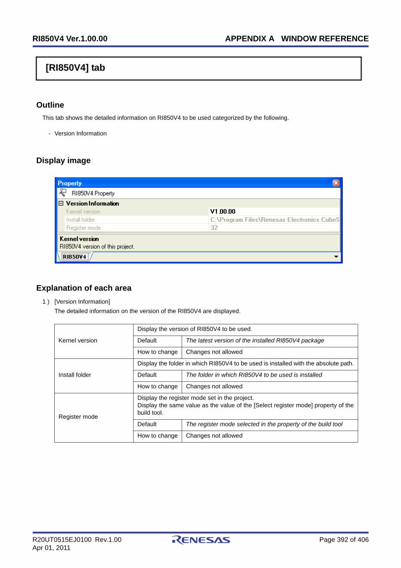
RI850V4 Ver.1.00.00 APPENDIX A WINDOW REFERENCE
R20UT0515EJ0100 Rev.1.00 Page 392 of 406Apr 01, 2011
[RI850V4] tab
Outline
This tab shows the detailed information on RI850V4 to be used categorized by the following.
- Version Information
Display image
Explanation of each area
1 ) [Version Information]The detailed information on the version of the RI850V4 are displayed.
Kernel version
Display the version of RI850V4 to be used.
Default The latest version of the installed RI850V4 package
How to change Changes not allowed
Install folder
Display the folder in which RI850V4 to be used is installed with the absolute path.
Default The folder in which RI850V4 to be used is installed
How to change Changes not allowed
Register mode
Display the register mode set in the project.Display the same value as the value of the [Select register mode] property of thebuild tool.
Default The register mode selected in the property of the build tool
How to change Changes not allowed

RI850V4 Ver.1.00.00 APPENDIX A WINDOW REFERENCE
R20UT0515EJ0100 Rev.1.00 Page 393 of 406Apr 01, 2011
[System Configuration File Related Information] tab
Outline
This tab shows the detailed information on the using system configuration file categorized by the following and theconfiguration can be changed.
- System information table file
- System information header file
- Entry file
- Run C preprocessor
Display image

RI850V4 Ver.1.00.00 APPENDIX A WINDOW REFERENCE
R20UT0515EJ0100 Rev.1.00 Page 394 of 406Apr 01, 2011
Explanation of each area
1 ) [System Information Table File]The detailed information on the system information table file are displayed and the configuration can be changed.
Generate a file
Select whether to generate a system information table file and whether to updatethe file when the system configuration file is changed.
Default Yes(It updates the file when the .cfg file is changed)(-i)
How to change Select from the drop-down list.
Restriction
Yes(It updates the file when the .cfg file is changed)(-i)
Generates a new system informationtable file and displays it on the projecttree.If the system configuration file ischanged when there is already asystem information table file, then thesystem information table file isupdated.
Yes(It does not update the file when the .cfg file is changed)(-ni)
Does not update the systeminformation table file when the systemconfiguration file is changed.An error occurs during build if thisitem is selected when the systeminformation table file does not exist.
No(It does not register the file to the project)(-ni)
Does not generate a systeminformation table file and does notdisplay it on the project tree.If this item is selected when there isalready a system information tablefile, then the file itself is not deleted.
Output folder
Specify the folder for outputting the system information table file.If a relative path is specified, the reference point of the path is the project folder.If an absolute path is specified, the reference point of the path is the project folder(unless the drives are different).The following macro name is available as an embedded macro.%BuildModeName%: Replaces with the build mode name.If this field is left blank, macro name "%BuildModeName%" will be displayed.This property is not displayed when [No(It does not register the file that is addedto the project)(-ni)] in the [Generate a file] property is selected.
Default %BuildModeName%
How to change Directly enter to the text box or edit by the Browse For Folderdialog box which appears when clicking the [...] button.
Restriction Up to 247 characters
File name
Specify the system information table file name.If the file name is changed, the name of the file displayed on the project tree.Use the extension ".s". If the extension is different or omitted, ".s" is automaticallyadded.You cannot specify the same file name as the value of the [File name] property inthe [Entry File] category.This property is not displayed when [No(It does not register the file that is addedto the project)(-ni)] in the [Generate a file] property is selected.
Default sit.s
How to change Directly enter to the text box.
Restriction Up to 259 characters
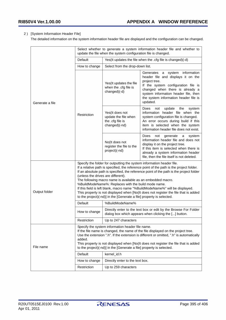
RI850V4 Ver.1.00.00 APPENDIX A WINDOW REFERENCE
R20UT0515EJ0100 Rev.1.00 Page 395 of 406Apr 01, 2011
2 ) [System Information Header File]The detailed information on the system information header file are displayed and the configuration can be changed.
Generate a file
Select whether to generate a system information header file and whether toupdate the file when the system configuration file is changed.
Default Yes(It updates the file when the .cfg file is changed)(-d)
How to change Select from the drop-down list.
Restriction
Yes(It updates the file when the .cfg file is changed)(-d)
Generates a system informationheader file and displays it on theproject tree.If the system configuration file ischanged when there is already asystem information header file, thenthe system information header file isupdated.
Yes(It does not update the file when the .cfg file is changed)(-nd)
Does not update the systeminformation header file when thesystem configuration file is changed.An error occurs during build if thisitem is selected when the systeminformation header file does not exist.
No(It does not register the file to the project)(-nd)
Does not generate a systeminformation header file and does notdisplay it on the project tree.If this item is selected when there isalready a system information headerfile, then the file itself is not deleted.
Output folder
Specify the folder for outputting the system information header file.If a relative path is specified, the reference point of the path is the project folder.If an absolute path is specified, the reference point of the path is the project folder(unless the drives are different).The following macro name is available as an embedded macro.%BuildModeName%: Replaces with the build mode name.If this field is left blank, macro name "%BuildModeName%" will be displayed.This property is not displayed when [No(It does not register the file that is addedto the project)(-nd)] in the [Generate a file] property is selected.
Default %BuildModeName%
How to change Directly enter to the text box or edit by the Browse For Folderdialog box which appears when clicking the [...] button.
Restriction Up to 247 characters
File name
Specify the system information header file name.If the file name is changed, the name of the file displayed on the project tree.Use the extension ".h". If the extension is different or omitted, ".h" is automaticallyadded.This property is not displayed when [No(It does not register the file that is addedto the project)(-nd)] in the [Generate a file] property is selected.
Default kernel_id.h
How to change Directly enter to the text box.
Restriction Up to 259 characters

RI850V4 Ver.1.00.00 APPENDIX A WINDOW REFERENCE
R20UT0515EJ0100 Rev.1.00 Page 396 of 406Apr 01, 2011
3 ) [Entry File]The detailed information on the entry file are displayed and the configuration can be changed.
Generate a file
Select whether to generate an entry file and whether to update the file when thesystem configuration file is changed.
Default Yes(It updates the file when the .cfg file is changed)(-e)
How to change Select from the drop-down list.
Restriction
Yes(It updates the file when the .cfg file is changed)(-e)
Generates an entry file and displays iton the project tree.If the system configuration file ischanged when there is already anentry file, then the entry file isupdated.
Yes(It does not update the file when the .cfg file is changed)(-ne)
Does not update the entry file whenthe system configuration file ischanged.An error occurs during build if thisitem is selected when the entry filedoes not exist.
No(It does not register the file to the project)(-ne)
Does not generate an entry file anddoes not display it on the project tree.If this item is selected when there isalready an entry file, then the file itselfis not deleted.
Output folder
Specify the folder for outputting the entry file.If a relative path is specified, the reference point of the path is the project folder.If an absolute path is specified, the reference point of the path is the project folder(unless the drives are different).The following macro name is available as an embedded macro.%BuildModeName%: Replaces with the build mode name.If this field is left blank, macro name "%BuildModeName%" will be displayed.This property is not displayed when [No(It does not register the file that is addedto the project)(-ne)] in the [Generate a file] property is selected.
Default %BuildModeName%
How to change Directly enter to the text box or edit by the Browse For Folderdialog box which appears when clicking the [...] button.
Restriction Up to 247 characters
File name
Specify the entry file.If the file name is changed, the name of the file displayed on the project tree.Use the extension ".s". If the extension is different or omitted, ".s" is automaticallyadded.You cannot specify the same file name as the value of the [File name] property inthe [System Information Table File] category.This property is not displayed when [No(It does not register the file that is addedto the project)(-ne)] in the [Generate a file] property is selected.
Default entry.s
How to change Directly enter to the text box.
Restriction Up to 259 characters

RI850V4 Ver.1.00.00 APPENDIX A WINDOW REFERENCE
R20UT0515EJ0100 Rev.1.00 Page 397 of 406Apr 01, 2011
4 ) [Run C Preprocessor]The detailed information on starting the C preprocessor are displayed and the configuration can be changed.
Run C preprocessor
Select whether to start the C preprocessor for the system configuration file beforethe configurator starts.Select [Yes(-T)] when macro definitions are specified in the system configurationfile.
Default No(-np)
How to change Select from the drop-down list.
RestrictionYes(-T)
Starts the C preprocessor.The include paths set by the C compiler arereferenced when the C preprocessor starts.
No(-np) Does not start the C preprocessor.

RI850V4 Ver.1.00.00 APPENDIX B FLOATING-POINT OPERATION FUNCTION
R20UT0515EJ0100 Rev.1.00 Page 398 of 406Apr 01, 2011
APPENDIX B FLOATING-POINT OPERATION FUNCTION
The RI850V4 supports the floating-point operation function of the V850E2M core. This makes floating-point operationsavailable within processing programs (e.g. tasks, cyclic handlers, and interrupt handlers).
The RI850V4 manipulates the following floating-point operation registers: "Register bank selection register BSEL" and"Floating-point configuration/status register FPSR". The user can change the settings from within processing programs asneeded by changing these values.
The values of BSEL and FPSR are essentially independent to each processing program, and are not inherited betweenprocessing programs.
In the following cases, however, the values of BSEL and FPSR are inherited between processing programs.
- If a task exception handler routine is started from a task, the BSEL and FPSR values of the task are inherited by thetask exception handler routine. After the task exception handler routine terminates, the setting returns to the value ithad before the routine was started.
- The RI850V4 does not manipulate BSEL or FPSR when an extended service call routine starts or ends. For thisreason, extended service call routines inherit the values of BSEL and FPSR from before they were started, and anychanges made from the processing program remain unchanged after the processing program ends.
See the table below for the register values when each processing program is initially started.
Table B-1 Startup Register Values of Each Processing Program
Note 1 The BSEL setting of 0x0 indicates that the system register bank group number is the CPU function group, andthe bank number is the Main bank.
Note 2 If a task is suspended, the BSEL and FPSR values from before the suspension are restored when the taskresumes.
Note 3 If a task is suspended, the BSEL and FPSR values from before the suspension are restored when the taskresumes.
Processing Program Initial BSEL Value Initial FPSR Value
Task 0x0 User setting
Task exception handling routine Value prior to startup inherited Value prior to startup inherited
Cyclic handler 0x0 User setting
Interrupt Handler 0x0 User setting
Extended Service Call Routine Value prior to startup inherited Value prior to startup inherited
CPU Exception Handler 0x0 User setting
Initialization Routine 0x0 User setting
Idle Routine 0x0 User setting

RI850V4 Ver.1.00.00 APPENDIX C INDEX
R20UT0515EJ0100 Rev.1.00 Page 399 of 406Apr 01, 2011
A
act_tsk ... 206
C
cal_svc ... 342
can_act ... 208
can_wup ... 227
chg_ims ... 339
chg_pri ... 214
clr_flg ... 253
D
data queues ... 76
fsnd_dtq ... 267
ifsnd_dtq ... 267
iprcv_dtq ... 270
ipsnd_dtq ... 264
iref_dtq ... 273
prcv_dtq ... 270
psnd_dtq ... 264
rcv_dtq ... 268
ref_dtq ... 273
snd_dtq ... 262
trcv_dtq ... 271
tsnd_dtq ... 265
dis_dsp ... 331
dis_int ... 337
dis_tex ... 237
dly_tsk ... 233
E
ena_dsp ... 332
ena_int ... 338
ena_tex ... 238
eventflags ... 67
clr_flg ... 253
iclr_flg ... 253
ipol_flg ... 256
iref_flg ... 260
iset_flg ... 252
pol_flg ... 256
ref_flg ... 260
set_flg ... 252
twai_flg ... 258
wai_flg ... 254
extended synchronization and communication functions
... 96
mutexes ... 96, 285
ext_tsk ... 211
F
fixed-sized memory pools ... 104
get_mpf ... 295
ipget_mpf ... 297
iref_mpf ... 302
irel_mpf ... 300
pget_mpf ... 297
ref_mpf ... 302
rel_mpf ... 300
tget_mpf ... 298
frsm_tsk ... 232
fsnd_dtq ... 267
G
get_ims ... 340
get_mpf ... 295
get_mpl ... 305
get_pri ... 216
get_tid ... 326
get_tim ... 317
I
iact_tsk ... 206
ical_svc ... 342
ican_act ... 208
ican_wup ... 227
APPENDIX C INDEX

RI850V4 Ver.1.00.00 APPENDIX C INDEX
R20UT0515EJ0100 Rev.1.00 Page 400 of 406Apr 01, 2011
ichg_ims ... 339
ichg_pri ... 214
iclr_flg ... 253
ifrsm_tsk ... 232
ifsnd_dtq ... 267
iget_ims ... 340
iget_pri ... 216
iget_tid ... 326
iget_tim ... 317
iloc_cpu ... 327
interrupt management functions ... 145, 336
chg_ims ... 339
dis_int ... 337
ena_int ... 338
get_ims ... 340
ichg_ims ... 339
iget_ims ... 340
ipget_mpf ... 297
ipget_mpl ... 307
ipol_flg ... 256
ipol_sem ... 245
iprcv_dtq ... 270
iprcv_mbx ... 280
ipsnd_dtq ... 264
iras_tex ... 235
iref_cyc ... 321
iref_dtq ... 273
iref_flg ... 260
iref_mbx ... 284
iref_mpf ... 302
iref_mpl ... 313
iref_mtx ... 292
iref_sem ... 249
iref_tex ... 240
iref_tsk ... 217
iref_tst ... 219
irel_mpf ... 300
irel_mpl ... 311
irel_wai ... 228
irot_rdq ... 324
irsm_tsk ... 231
iset_flg ... 252
iset_tim ... 316
isig_sem ... 248
isnd_mbx ... 276
ista_cyc ... 318
ista_tsk ... 210
istp_cyc ... 320
isus_tsk ... 229
iunl_cpu ... 329
iwup_tsk ... 225
L
loc_cpu ... 327
loc_mtx ... 286
M
mailboxes ... 89
iprcv_mbx ... 280
iref_mbx ... 284
isnd_mbx ... 276
prcv_mbx ... 280
rcv_mbx ... 278
ref_mbx ... 284
snd_mbx ... 276
trcv_mbx ... 282
Main window ... 384
memory pool management functions ... 103
fixed-sized memory pools ... 104, 294
variable-sized memory pools ... 112, 304
mutexes ... 96
iref_mtx ... 292
loc_mtx ... 286
ploc_mtx ... 288
ref_mtx ... 292
tloc_mtx ... 289
unl_mtx ... 291
P
pget_mpf ... 297
pget_mpl ... 307
ploc_mtx ... 288
pol_flg ... 256
RI850V4 Ver.1.00.00 APPENDIX C INDEX
R20UT0515EJ0100 Rev.1.00 Page 401 of 406Apr 01, 2011
pol_sem ... 245
prcv_dtq ... 270
prcv_mbx ... 280
Project Tree panel ... 386
Property panel ... 389
psnd_dtq ... 264
R
ras_tex ... 235
rcv_dtq ... 268
rcv_mbx ... 278
ref_cyc ... 321
ref_dtq ... 273
ref_flg ... 260
ref_mbx ... 284
ref_mpf ... 302
ref_mpl ... 313
ref_mtx ... 292
ref_sem ... 249
ref_tex ... 240
ref_tsk ... 217
ref_tst ... 219
rel_mpf ... 300
rel_mpl ... 311
rel_wai ... 228
RI850V4 ... 15
[RI850V4] tab ... 392
rot_rdq ... 324
rsm_tsk ... 231
S
semaphores ... 61
ipol_sem ... 245
iref_sem ... 249
isig_sem ... 248
pol_sem ... 245
ref_sem ... 249
sig_sem ... 248
twai_sem ... 246
wai_sem ... 243
service call management functions ... 162, 341
cal_svc ... 342
ical_svc ... 342
set_flg ... 252
set_tim ... 316
sig_sem ... 248
slp_tsk ... 222
snd_dtq ... 262
snd_mbx ... 276
sns_dpn ... 335
sns_dsp ... 333
sns_loc ... 330
sns_tex ... 239
sta_cyc ... 318
sta_tsk ... 210
stp_cyc ... 320
sus_tsk ... 229
synchronization and communication functions ... 61
data queues ... 76, 261
eventflags ... 67, 251
mailboxes ... 89, 275
semaphores ... 61, 242
[System Configuration File Related Information] tab
... 393
system state management functions ... 129, 323
dis_dsp ... 331
ena_dsp ... 332
get_tid ... 326
iget_tid ... 326
iloc_cpu ... 327
irot_rdq ... 324
iunl_cpu ... 329
loc_cpu ... 327
rot_rdq ... 324
sns_dpn ... 335
sns_dsp ... 333
sns_loc ... 330
unl_cpu ... 329
vsta_sch ... 325
T
task dependent synchronization functions ... 43, 221

RI850V4 Ver.1.00.00 APPENDIX C INDEX
R20UT0515EJ0100 Rev.1.00 Page 402 of 406Apr 01, 2011
can_wup ... 227
dly_tsk ... 233
frsm_tsk ... 232
ican_wup ... 227
ifrsm_tsk ... 232
irel_wai ... 228
irsm_tsk ... 231
isus_tsk ... 229
iwup_tsk ... 225
rel_wai ... 228
rsm_tsk ... 231
slp_tsk ... 222
sus_tsk ... 229
tslp_tsk ... 223
wup_tsk ... 225
task exception handling functions ... 54, 234
dis_tex ... 237
ena_tex ... 238
iras_tex ... 235
iref_tex ... 240
ras_tex ... 235
ref_tex ... 240
sns_tex ... 239
task management functions ... 27, 205
act_tsk ... 206
can_act ... 208
chg_pri ... 214
ext_tsk ... 211
get_pri ... 216
iact_tsk ... 206
ican_act ... 208
ichg_pri ... 214
iget_pri ... 216
iref_tsk ... 217
iref_tst ... 219
ista_tsk ... 210
ref_tsk ... 217
ref_tst ... 219
sta_tsk ... 210
ter_tsk ... 212
ter_tsk ... 212
tget_mpf ... 298
tget_mpl ... 309
time management functions ... 120, 315
get_tim ... 317
iget_tim ... 317
iref_cyc ... 321
iset_tim ... 316
ista_cyc ... 318
istp_cyc ... 320
ref_cyc ... 321
set_tim ... 316
sta_cyc ... 318
stp_cyc ... 320
tloc_mtx ... 289
trcv_dtq ... 271
trcv_mbx ... 282
tslp_tsk ... 223
tsnd_dtq ... 265
twai_flg ... 258
twai_sem ... 246
U
unl_cpu ... 329
unl_mtx ... 291
V
variable-sized memory pools ... 112
get_mpl ... 305
ipget_mpl ... 307
iref_mpl ... 313
irel_mpl ... 311
pget_mpl ... 307
ref_mpl ... 313
rel_mpl ... 311
tget_mpl ... 309
vsta_sch ... 325
W
wai_flg ... 254
wai_sem ... 243
wup_tsk ... 225

Revision Record
Rev. DateDescription
Page Summary
1.00 Apr 01, 2011 - First Edition issued

RI850V4 User’s Manual: Coding Publication Date: Rev.1.00 Apr 01, 2011 Published by: Renesas Electronics Corporation

http://www.renesas.comRefer to "http://www.renesas.com/" for the latest and detailed information.
Renesas Electronics America Inc. 2880 Scott Boulevard Santa Clara, CA 95050-2554, U.S.A.Tel: +1-408-588-6000, Fax: +1-408-588-6130Renesas Electronics Canada Limited1101 Nicholson Road, Newmarket, Ontario L3Y 9C3, CanadaTel: +1-905-898-5441, Fax: +1-905-898-3220Renesas Electronics Europe LimitedDukes Meadow, Millboard Road, Bourne End, Buckinghamshire, SL8 5FH, U.KTel: +44-1628-585-100, Fax: +44-1628-585-900Renesas Electronics Europe GmbHArcadiastrasse 10, 40472 Düsseldorf, Germany Tel: +49-211-65030, Fax: +49-211-6503-1327 Renesas Electronics (China) Co., Ltd.7th Floor, Quantum Plaza, No.27 ZhiChunLu Haidian District, Beijing 100083, P.R.China Tel: +86-10-8235-1155, Fax: +86-10-8235-7679Renesas Electronics (Shanghai) Co., Ltd.Unit 204, 205, AZIA Center, No.1233 Lujiazui Ring Rd., Pudong District, Shanghai 200120, China Tel: +86-21-5877-1818, Fax: +86-21-6887-7858 / -7898 Renesas Electronics Hong Kong LimitedUnit 1601-1613, 16/F., Tower 2, Grand Century Place, 193 Prince Edward Road West, Mongkok, Kowloon, Hong KongTel: +852-2886-9318, Fax: +852 2886-9022/9044Renesas Electronics Taiwan Co., Ltd.7F, No. 363 Fu Shing North Road Taipei, TaiwanTel: +886-2-8175-9600, Fax: +886 2-8175-9670Renesas Electronics Singapore Pte. Ltd. 1 harbourFront Avenue, #06-10, keppel Bay Tower, Singapore 098632Tel: +65-6213-0200, Fax: +65-6278-8001Renesas Electronics Malaysia Sdn.Bhd. Unit 906, Block B, Menara Amcorp, Amcorp Trade Centre, No. 18, Jln Persiaran Barat, 46050 Petaling Jaya, Selangor Darul Ehsan, MalaysiaTel: +60-3-7955-9390, Fax: +60-3-7955-9510Renesas Electronics Korea Co., Ltd.11F., Samik Lavied' or Bldg., 720-2 Yeoksam-Dong, Kangnam-Ku, Seoul 135-080, KoreaTel: +82-2-558-3737, Fax: +82-2-558-5141
SALES OFFICES
© 2011 Renesas Electronics Corporation. All rights reserved.
Colophon 1.0

RI850V4
R20UT0515EJ0100
Related Documents