© 2015 Fann Instrument Company RheoVADR ® Rheometer Instruction Manual Manual No. D00845847, Revision E Instrument No. 102267855 Software Version 1.5 DNA™ System Compatible

Welcome message from author
This document is posted to help you gain knowledge. Please leave a comment to let me know what you think about it! Share it to your friends and learn new things together.
Transcript

© 2015 Fann Instrument Company
RheoVADR® Rheometer
Instruction Manual
Manual No. D00845847, Revision E
Instrument No. 102267855 Software Version 1.5
DNA™ System Compatible
D00845847 Revision E, October 2015 2
RheoVADR® Rheometer Instruction Manual
©2015 Fann Instrument Company
Houston, Texas, USA
All rights reserved. No part of this work covered by the copyright hereon may be reproduced or copied in any form or by any means (graphic, electronic, or mechanical) without first receiving the written permission of Fann Instrument Company, Houston, Texas, USA.
Printed in USA.
The information contained in this document includes concepts, methods, and apparatus which may be covered by U.S. Patents. Fann Instrument Company reserves the right to make improvements in design, construction, and appearance of our products without prior notice.
FANN® and the FANN logo are registered trademarks of Fann Instrument Company in the United States and/or other countries. All other trademarks mentioned in the operating instructions are the exclusive property of the respective manufacturers.
RheoVADR® is a registered trademark of Fann Instrument Company.
Contact Fann Instrument Company
Phone 1-281-871-4482
1-800-347-0450
Fax 1-281-871-4358
Postal Address Fann Instrument Company P.O. Box 4350 Houston, Texas, 77210 USA
Shipping Address Fann Instrument Company 14851 Milner Road, Gate 5 Houston, Texas, 77032, USA
Online www.fann.com [email protected]

RheoVADR® Rheometer Instruction Manual
D00845847 Revision E, October 2015 3
Table of Contents 1 Introduction .............................................................................................................. 6
1.1 Document Conventions .................................................................................... 7 2 Safety ....................................................................................................................... 8
2.1 Safe Electrical Operation .................................................................................. 8 2.2 Heated Sample Cup ......................................................................................... 8
3 Features and Specifications ..................................................................................... 9 3.1 Rheometer Features ........................................................................................ 9 3.2 Rheometer Specifications .............................................................................. 11 * Powered by universal power supply (UPS) provided by Fann. ............................. 11 3.3 Rotor and Bob Specifications ......................................................................... 12 3.4 Operating Specifications ................................................................................ 12
4 Installation .............................................................................................................. 13 5 Operation ............................................................................................................... 14
5.1 Instrument Start-up ........................................................................................ 16 5.2 Manual Operating Instructions ........................................................................ 18 5.2.1 Choosing speeds ....................................................................................... 18 5.2.2 Recording and Saving data ....................................................................... 18 5.2.3 Measuring Gel Strength ............................................................................. 19 5.2.4 Stopping a test .......................................................................................... 19 5.2.5 Shutting down the rheometer ..................................................................... 19 5.3 API Test Profile .............................................................................................. 20 5.3.1 User Profiles .............................................................................................. 21 5.4 Set-up Mode .................................................................................................. 22 5.4.1 Changing temperature units ...................................................................... 22 5.4.2 Initiating temperature calibration ................................................................ 23 5.4.3 Initiating sensor calibration ........................................................................ 23 5.4.4 Choosing address ...................................................................................... 24 5.4.5 Choosing Rotor-Bob Combination ............................................................. 25 5.4.6 Applying Firmware Update ........................................................................ 26 5.4.7 Installing User Profiles ............................................................................... 28 5.5 Rotor Removal and Installation ...................................................................... 29 5.6 Bob Removal and Installation ......................................................................... 29
6 Troubleshooting and Maintenance ......................................................................... 30 7 Accessories ............................................................................................................ 31
RheoVADR® Rheometer Instruction Manual
D00845847 Revision E, October 2015 4
8 Parts List ................................................................................................................ 32 9 Declaration of Conformity ....................................................................................... 36 10 Warranty and Returns ............................................................................................ 37
10.1 Warranty ........................................................................................................ 37 10.2 Returns .......................................................................................................... 37
Appendix A API Profiles ................................................................................................ 38 Appendix B Viscosity Calculations ................................................................................ 41

RheoVADR® Rheometer Instruction Manual
D00845847 Revision E, October 2015 5
List of Figures Figure 3-1 RheoVADR® Rheometer (front and back) .................................................... 10 Figure 5-1 RheoVADR® Rheometer Keypad ................................................................. 14 Figure 5-2 Start Up Message ........................................................................................ 16 Figure 5-3 System Information ...................................................................................... 16 Figure 5-4 Data Display ................................................................................................ 16 Figure 5-5 API Test Profiles (pages 1 and 2) ................................................................ 20 Figure 5-6 Test in Progress (API Test Mode) ................................................................ 21 Figure 5-7 Test Results (end of test) ............................................................................. 21 Figure 5-8 SETUP Mode (page 1) ................................................................................ 22 Figure 5-9 SETUP Mode (page 2) ................................................................................ 22 Figure 5-10 Fluid Calibration ......................................................................................... 24 Figure 5-11 Rotor-Bob Combinations ............................................................................ 25 Figure 5-12 Bob and Bob Shaft ..................................................................................... 29 Figure 8-1 RheoVADR® Rheometer Assembly, View 1 ................................................. 34 Figure 8-2 RheoVADR® Rheometer Assembly, View 2 ................................................. 35
List of Tables
Table 3-1 RheoVADR® Rheometer Specifications ........................................................ 11 Table 3-2 Rotor-Bob Specifications and Constants ....................................................... 12 Table 3-3 Range of Environmental Conditions .............................................................. 12 Table 5-1 RheoVADR® Keypad Functions .................................................................... 15 Table 5-2 Viscosity Standards for Springs .................................................................... 23 Table 7-1 Accessories for RheoVADR® Rheometer ...................................................... 31 Table 8-1 RheoVADR® Rheometer Models ................................................................... 32 Table 8-2 RheoVADR® Rheometer Parts ...................................................................... 32 Table A-1 API Six Speed & Gel Profile ......................................................................... 39 Table A-2 API PV/YP & Gel Profile ............................................................................... 39 Table A-3 API Gel Profile .............................................................................................. 39 Table A-4 API Cement Profile ....................................................................................... 40 Table B-1 Rotor-Bob Factor (C) .................................................................................... 41 Table B-2 Torsion Spring Specifications ....................................................................... 42

RheoVADR® Rheometer Instruction Manual
D00845847 Revision E, October 2015 6
1 Introduction
The RheoVADR® Variable Automated Digital Rheometer is the latest addition to the Fann viscometer family. RheoVADR® is a direct-reading instrument for evaluating the rheological properties of fluids, Newtonian and non-Newtonian. The advantages of the this rheometer are its digital display, pre-programmed API tests, data recording feature, and speed range — 12 preset and variable speeds from 0.01 rpm to 999 rpm.
This design includes a rotor, bob, torsion spring, and a stainless steel sample cup for testing according to American Petroleum Institute Recommended Practice. This instrument is powered by a universal power supply, provided by Fann.
This instruction manual supports software version 1.5.

RheoVADR® Rheometer Instruction Manual
D00845847 Revision E, October 2015 7
1.1 Document Conventions
The following icons are used as necessary in this instruction manual.
NOTE. Notes emphasize additional information that may be useful to the reader.
CAUTION. Describes a situation or practice that requires operator awareness or action in order to avoid undesirable consequences.
MANDATORY ACTION. Gives directions that, if not observed, could result in loss of data or in damage to equipment.
WARNING! Describes an unsafe condition or practice that if not corrected, could result in personal injury or threat to health.
ELECTRICITY WARNING! Alerts the operator that there is risk of electric shock.
HOT SURFACE! Alerts the operator that there is a hot surface and that there is risk of getting burned if the surface is touched.
EXPLOSION RISK! Alerts the operator that there is risk of explosion.

RheoVADR® Rheometer Instruction Manual
D00845847 Revision E, October 2015 8
2 Safety
Safe laboratory practices and procedures should be observed while operating and maintaining the rheometer. This section lists some precautions to follow.
2.1 Safe Electrical Operation
This instrument is driven by universal power supply provided by Fann (100V to 240V, 50/60 Hz). Heated sample cups and recirculating sample cups (optional) are electrically heated.
Make sure the power and other wiring associated with this rheometer and electrically heated sample cups are in good condition and properly grounded.
Make sure the rheometer’s power switch is in the OFF position and unplugged from the source before cleaning, repairing or performing maintenance.
Keep hands, clothes and other objects away from the rotating parts of the machine.
2.2 Heated Sample Cup
See Table 7-1 for heated sample cups available for purchase separately from Fann.
When using the heated sample cups, wear the proper hand protection to avoid getting burned.
When using heated sample cups, do NOT exceed 200oF (93oC).
RheoVADR® Rheometer Instruction Manual
D00845847 Revision E, October 2015 9
3 Features and Specifications
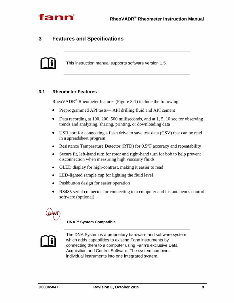
This instruction manual supports software version 1.5.
3.1 Rheometer Features
RheoVADR® Rheometer features (Figure 3-1) include the following:
• Preprogrammed API tests— API drilling fluid and API cement • Data recording at 100, 200, 500 milliseconds, and at 1, 5, 10 sec for observing
trends and analyzing, sharing, printing, or downloading data • USB port for connecting a flash drive to save test data (CSV) that can be read
in a spreadsheet program • Resistance Temperature Detector (RTD) for 0.5°F accuracy and repeatability
• Secure fit, left-hand turn for rotor and right-hand turn for bob to help prevent disconnection when measuring high viscosity fluids
• OLED display for high-contrast, making it easier to read
• LED-lighted sample cup for lighting the fluid level
• Pushbutton design for easier operation
• RS485 serial connector for connecting to a computer and instantaneous control software (optional)
DNA™ System Compatible
The DNA System is a proprietary hardware and software system which adds capabilities to existing Fann instruments by connecting them to a computer using Fann’s exclusive Data Acquisition and Control Software. The system combines individual instruments into one integrated system.

RheoVADR® Rheometer Instruction Manual
D00845847 Revision E, October 2015 10
Figure 3-1 RheoVADR® Rheometer (front and back)

RheoVADR® Rheometer Instruction Manual
D00845847 Revision E, October 2015 11
3.2 Rheometer Specifications
Table 3-1 RheoVADR® Rheometer Specifications
Category Specification
Torsion Spring F1, F2, F0.2
Rotors R1, R2, R3, R1 Closed End, R2 Closed End
Bobs B1, B2, B3, B4, B5 Operating Temperature Range 40°F to 125°F (4.44°C to 51.7°C) Automatic Tests 4 Pre-programmed API tests Sample Cup Volume 350 mL Sample Temperature 200°F (93°C) Temperature Measurements RTD Temperature Accuracy 0.5°F
Speed Range Variable 0.01 to 999.9 rpm 12 Preset: 600, 300, 200, 100, 60, 30, 20, 10, 6, 3, 2, 1
Speed Accuracy 0.001 rpm Shear Rate 0.01 sec-1 to 1700 sec-1 Dial Resolution 0.1 Dial Accuracy 0.5 cP Range (R1, B1, F1) 0.1 to 9M (displays 9999 cP max) Ports Power, RS485 Serial, USB Data Port USB Flash Drive Data Recording Speeds (intervals) 100, 200 & 500 ms; 1, 5, & 10 sec
Dimensions 16 x 5 x 9.5 inches 40.6 x 12.7 x 24 centimeters
Weight 15 lb (6.8 kg) Power Requirement 100V to 250V, AC, 50/60 Hz, 100W*
* Powered by universal power supply (UPS) provided by Fann.

RheoVADR® Rheometer Instruction Manual
D00845847 Revision E, October 2015 12
3.3 Rotor and Bob Specifications
Table 3-2 Rotor-Bob Specifications and Constants
ROTOR-BOB R1 B1 R2 B1 R3 B1 R1 B2 R1 B3 R1 B4 R1B5 Rotor Radius, R0 (cm) 1.8415 1.7588 2.5866 1.8415 1.8415 1.8415 1.8415
Bob Radius, Ri (cm) 1.7245 1.7245 1.7245 1.2276 0.8622 0.8622 1.59829
Bob Height, L (cm) 3.8 3.8 3.8 3.8 3.8 1.9 3.8
Shear Gap in Annulus (cm) 0.117 0.0343 0.8261 0.6139 0.9793 0.9793 0.2432
Radii Ratio, Ri /R0 0.9365 0.9805 0.667 0.666 0.468 0.468 0.8679
Maximum Use Temperature (oC) 93 93 93 93 93 93 93
Minimum Use Temperature (oC) 0 0 0 0 0 0 0
Overall Instrument Constant, K Standard F1 Torsion Spring, η = Kfθ/N
300 94.18 1355 2672 7620 15,200 703
Shear Rate Constant k3 (sec-1 per rpm) 1.7023 5.4225 0.377 0.377 0.268 0.268 0.8489
Shear Stress Constant for Effective Bob Surface k2 (cm-3)
0.01323 0.01323 0.01323 0.0261 0.0529 0.106 0.01546
3.4 Operating Specifications
Table 3-3 Range of Environmental Conditions
Maximum Altitude 6562 ft (2000 m) Temperature Range 39oF to 122oF (4oC to 50oC)
Maximum Relative Humidity (RH) 80% RH at 87.8oF (31oC) or less 50% RH at 104oF (40oC)
RheoVADR® Rheometer Instruction Manual
D00845847 Revision E, October 2015 13
4 Installation
The rheometer should be placed where there is easy access to the power cord plug for disconnection.
Consideration should be given to the location where samples are prepared and equipment is cleaned when the test is completed. There should be sufficient storage area nearby for commonly used tools, as well as consumables.
RheoVADR® Rheometer Instruction Manual
D00845847 Revision E, October 2015 14
5 Operation
To start a test, add 350 mL of sample to the stainless steel sample cup. The sample cup has a line that marks 350 mL. A scribed line on the rotor indicates proper immersion depth.
Damage to the bob shaft bearing may occur if the immersion depth is exceeded.
If other sample holders are used, the space between the bottom of the rotor and the bottom of the sample holder should be one-half inch (1.27cm) or greater.
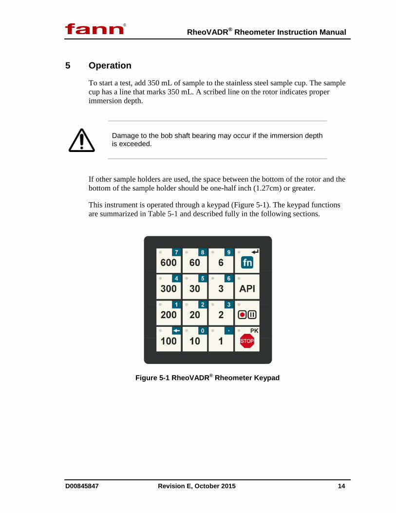
This instrument is operated through a keypad (Figure 5-1). The keypad functions are summarized in Table 5-1 and described fully in the following sections.
Figure 5-1 RheoVADR® Rheometer Keypad

RheoVADR® Rheometer Instruction Manual
D00845847 Revision E, October 2015 15
Table 5-1 RheoVADR® Keypad Functions
Key name Use
Preprogrammed Speeds
Press white number keys to activate speeds of 1, 2, 3, 6, 10, 20, 30, 60, 100, 200, 300, or 600 rpm
Function fn
Press to activate blue second function keys
Use as Enter key ↵
Press and hold ~ 5 seconds to ZERO the dial reading. See NOTE below.
Blue Second Function
Speed: Press fn key and then press blue number keys to enter speed. Press fn key again as Enter key.
Backspace ← : When fn key is active, this key acts as backspace to delete last digit entered
Decimal . : When fn key is active, use decimal key to enter decimal point
API Press this key to open API menu.
Record/Pause Press once to record; press again to pause
Record data at these rates: 100, 200, 500 milliseconds; and 1, 5,10 seconds
PK Press and hold STOP for ~ 5 seconds to activate peak mode. The unit displays the peak dial reading (gel strength). To leave peak mode, press STOP again.
STOP
Press to stop the Rheometer or stop a test or recording in progress.
Press to exit a program or step
Press to turn on light
Zero the dial reading without fluid and then perform the calibration to obtain the most accurate measurements.
RheoVADR® Rheometer Instruction Manual
D00845847 Revision E, October 2015 16
5.1 Instrument Start-up
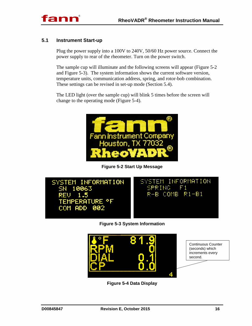
Plug the power supply into a 100V to 240V, 50/60 Hz power source. Connect the power supply to rear of the rheometer. Turn on the power switch.
The sample cup will illuminate and the following screens will appear (Figure 5-2 and Figure 5-3). The system information shows the current software version, temperature units, communication address, spring, and rotor-bob combination. These settings can be revised in set-up mode (Section 5.4).
The LED light (over the sample cup) will blink 5 times before the screen will change to the operating mode (Figure 5-4).
Figure 5-2 Start Up Message
Figure 5-3 System Information
Figure 5-4 Data Display
Continuous Counter (seconds) which increments every second.

RheoVADR® Rheometer Instruction Manual
D00845847 Revision E, October 2015 17
The data display (Figure 5-4) lists the temperature (oF), speed (RPM), dial reading (DIAL), and the viscosity in centipoise (cP) in real-time. In the lower right corner of the display, a counter (seconds) shows how long a set speed is running.
The temperature units can be set to degrees Fahrenheit or Celsius. See Section 5.4 for instructions.
The counter resets to Zero and starts counting again whenever you press STOP, any speed key, or enter an action.

RheoVADR® Rheometer Instruction Manual
D00845847 Revision E, October 2015 18
5.2 Manual Operating Instructions
A flash drive (not provided) must be connected to save data.
5.2.1 Choosing speeds
• Press white number keys to select preset speeds: 600, 300, 200, 100, 60, 30, 20, 10, 6, 3, 2 or 1
• Press fn key and blue keys (and decimal key if needed) to enter manual speeds. Then, press fn to activate the speed entered.
5.2.2 Recording and Saving data
• A flash drive must be connected to save data.
• In API mode, test results are automatically recorded to a flash drive. The last test data from API programs is always available to view.
• Press Record/Pause key once to begin recording.
• Select recording rate by using blue second function keys.
• Press Record/Pause again to pause recording.
• Press Record/Pause again to continue recording.
• While recording, data is saved in the same file.
• To save data in another file (different name), press STOP, and then Record/Pause to record.
• To end recording and not file press STOP.
File name includes the serial number of the RheoVADR.

RheoVADR® Rheometer Instruction Manual
D00845847 Revision E, October 2015 19
5.2.3 Measuring Gel Strength
• Press the STOP button and hold it for 5 seconds. This activates the peak mode (PK) dial reading (shown below).
• The instrument displays the peak dial reading for subsequent speed.
• To get out of peak mode, press STOP.
5.2.4 Stopping a test
• Press STOP.
5.2.5 Shutting down the rheometer
• Press STOP.
• Turn the power switch (back of instrument) to OFF position (Figure 3-1).
Peak mode, PK
Record/Pause
RheoVADR® Rheometer Instruction Manual
D00845847 Revision E, October 2015 20
5.3 API Test Profile
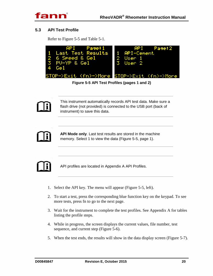
Refer to Figure 5-5 and Table 5-1.
Figure 5-5 API Test Profiles (pages 1 and 2)
This instrument automatically records API test data. Make sure a flash drive (not provided) is connected to the USB port (back of instrument) to save this data.
API Mode only. Last test results are stored in the machine memory. Select 1 to view the data (Figure 5-5, page 1).
API profiles are located in Appendix A API Profiles.
1. Select the API key. The menu will appear (Figure 5-5, left).
2. To start a test, press the corresponding blue function key on the keypad. To see more tests, press fn to go to the next page.
3. Wait for the instrument to complete the test profiles. See Appendix A for tables listing the profile steps.
4. While in progress, the screen displays the current values, file number, test sequence, and current step (Figure 5-6).
5. When the test ends, the results will show in the data display screen (Figure 5-7).

RheoVADR® Rheometer Instruction Manual
D00845847 Revision E, October 2015 21
6. Press fn to see more results. Press STOP to exit.
Figure 5-6 Test in Progress (API Test Mode)
During testing, the temperature, speed, dial reading, and viscosity (cP) will be shown. Also, the total steps (TS), current step (CS), and counter will be displayed.
Figure 5-7 Test Results (end of test)
5.3.1 User Profiles
User 1 and User 2 (Figure 5-5) are custom profiles.
See Section 5.4.7 for instructions to load the profiles onto the rheometer.
Fann Instrument Company can create User profiles for loading on your instrument using a USB flash drive. Contact Fann Instrument Company for customizing your User profiles.

RheoVADR® Rheometer Instruction Manual
D00845847 Revision E, October 2015 22
5.4 Set-up Mode
This section describes the functions available in SETUP mode (shown below).
To enter SETUP mode, press and hold STOP, and then turn on the power.
Wait for the SETUP menu to appear.
Figure 5-8 SETUP Mode (page 1)
Figure 5-9 SETUP Mode (page 2)
From the first SETUP menu, you must press fn to go to the next page (Figure 5-9).
You can exit SETUP mode, by pressing STOP.
5.4.1 Changing temperature units
• Press blue key 1 to change units. (Fahrenheit is default temperature unit.)
• Press STOP to exit and return to previous menu.

RheoVADR® Rheometer Instruction Manual
D00845847 Revision E, October 2015 23
5.4.2 Initiating temperature calibration
• Press blue key 2 to select temperature calibration.
• Follow temperature calibration steps as shown on screen.
• Press STOP to exit and return to previous menu.
Use an RTD calibrator (part no. 102355369, sold separately) for calibrating temperature. Temperature calibration is always performed in Celsius (°C).
5.4.3 Initiating sensor calibration
• Press blue key 3 to begin sensor calibration (Figure 5-8).
• Choose the appropriate standard for the spring (Table 5-2). The instrument will prompt you to use the appropriate fluid.
Table 5-2 Viscosity Standards for Springs
Spring Viscosity Standard (cp)
Max Calibration Speed (rpm)
F1 200 450 F2 500 360 F3 500 540 F4 1000 360 F5 1000 450
F10 2000 450
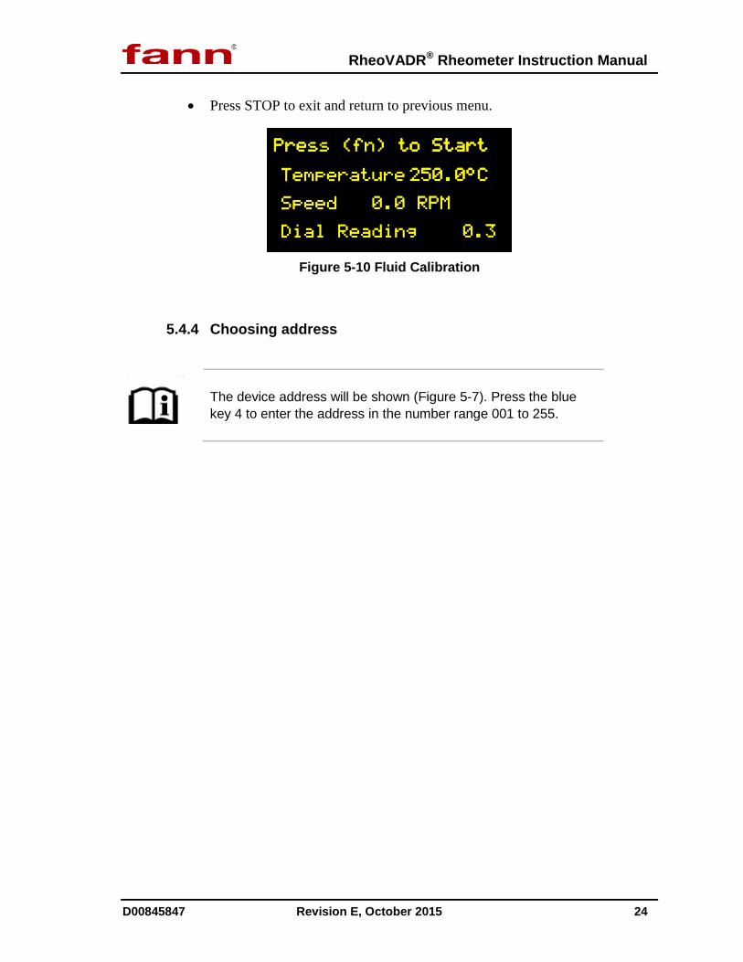
• When ready, press fn to start (Figure 5-10).
The unit will step through different speeds and compile sensor data. When this process finishes, the user will be prompted to enter the viscosity (cP) of the fluid at the measured temperature. The system uses this reference measurement (cP) to correlate the table it has compiled, and then it calibrates the dial readings to offset for nonlinearities in the measurement system.
RheoVADR® Rheometer Instruction Manual
D00845847 Revision E, October 2015 24
• Press STOP to exit and return to previous menu.
Figure 5-10 Fluid Calibration
5.4.4 Choosing address
The device address will be shown (Figure 5-7). Press the blue key 4 to enter the address in the number range 001 to 255.
RheoVADR® Rheometer Instruction Manual
D00845847 Revision E, October 2015 25
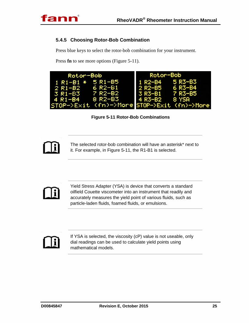
5.4.5 Choosing Rotor-Bob Combination
Press blue keys to select the rotor-bob combination for your instrument.
Press fn to see more options (Figure 5-11).
Figure 5-11 Rotor-Bob Combinations
The selected rotor-bob combination will have an asterisk* next to it. For example, in Figure 5-11, the R1-B1 is selected.
Yield Stress Adapter (YSA) is device that converts a standard oilfield Couette viscometer into an instrument that readily and accurately measures the yield point of various fluids, such as particle-laden fluids, foamed fluids, or emulsions.
If YSA is selected, the viscosity (cP) value is not useable, only dial readings can be used to calculate yield points using mathematical models.
RheoVADR® Rheometer Instruction Manual
D00845847 Revision E, October 2015 26
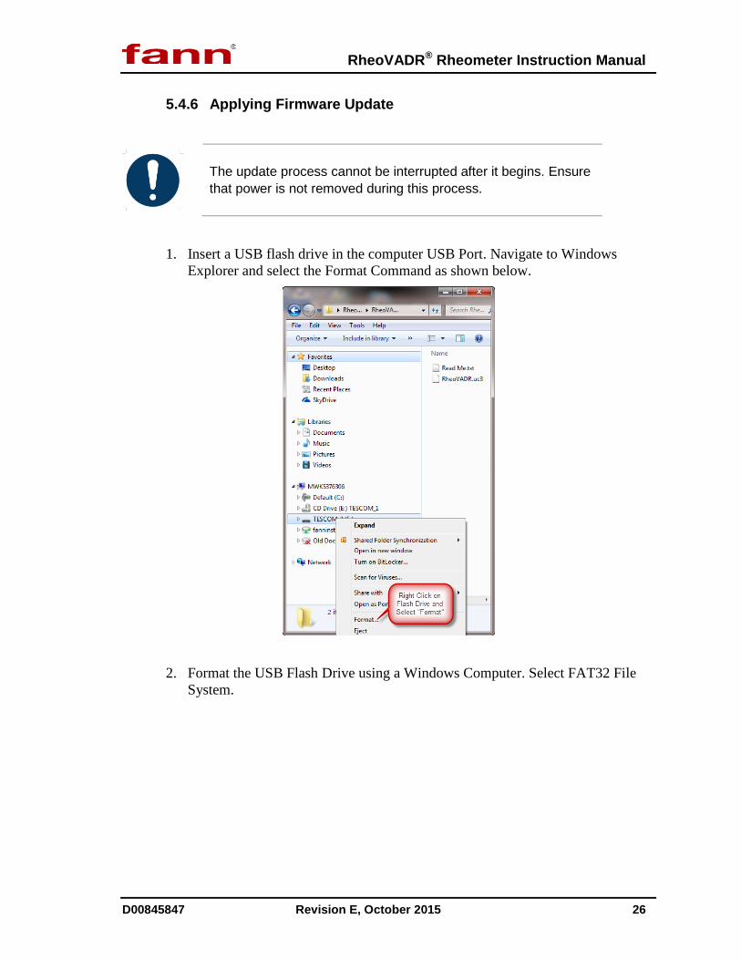
5.4.6 Applying Firmware Update
The update process cannot be interrupted after it begins. Ensure that power is not removed during this process.
1. Insert a USB flash drive in the computer USB Port. Navigate to Windows Explorer and select the Format Command as shown below.
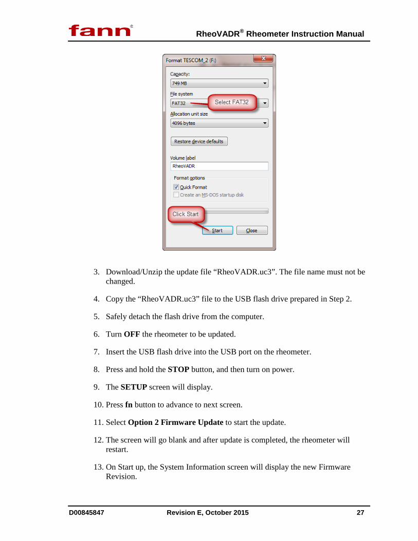
2. Format the USB Flash Drive using a Windows Computer. Select FAT32 File System.
RheoVADR® Rheometer Instruction Manual
D00845847 Revision E, October 2015 27
3. Download/Unzip the update file “RheoVADR.uc3”. The file name must not be changed.
4. Copy the “RheoVADR.uc3” file to the USB flash drive prepared in Step 2.
5. Safely detach the flash drive from the computer.
6. Turn OFF the rheometer to be updated.
7. Insert the USB flash drive into the USB port on the rheometer.
8. Press and hold the STOP button, and then turn on power.
9. The SETUP screen will display.
10. Press fn button to advance to next screen.
11. Select Option 2 Firmware Update to start the update.
12. The screen will go blank and after update is completed, the rheometer will restart.
13. On Start up, the System Information screen will display the new Firmware Revision.
RheoVADR® Rheometer Instruction Manual
D00845847 Revision E, October 2015 28
5.4.7 Installing User Profiles
Fann Instrument Company can create User profiles for loading on your instrument using a USB flash drive. Contact Fann Instrument Company for customizing your User profiles.
• To load, the custom profile, insert the USB flash drive into rheometer USB port.
• From SETUP, press blue keys 3 or 4 (Figure 5-9) to load UP1 or UP2, respectively.
RheoVADR® Rheometer Instruction Manual
D00845847 Revision E, October 2015 29
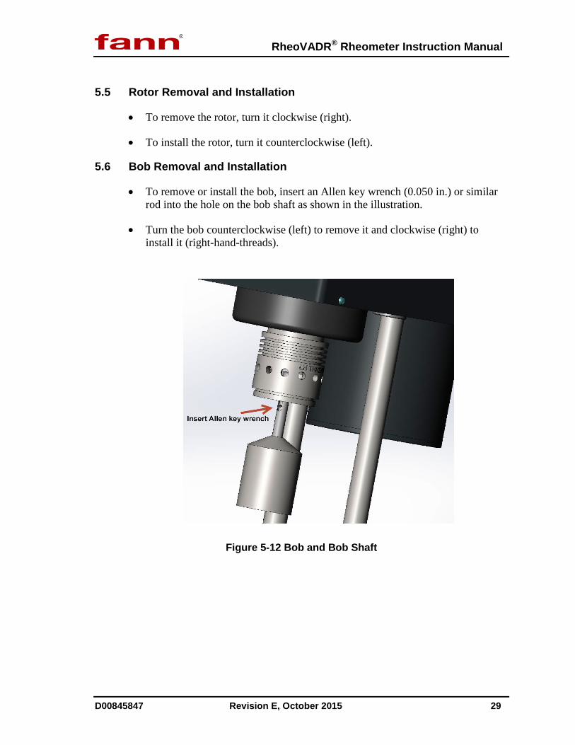
5.5 Rotor Removal and Installation
• To remove the rotor, turn it clockwise (right).
• To install the rotor, turn it counterclockwise (left).
5.6 Bob Removal and Installation
• To remove or install the bob, insert an Allen key wrench (0.050 in.) or similar rod into the hole on the bob shaft as shown in the illustration.
• Turn the bob counterclockwise (left) to remove it and clockwise (right) to install it (right-hand-threads).
Figure 5-12 Bob and Bob Shaft

RheoVADR® Rheometer Instruction Manual
D00845847 Revision E, October 2015 30
6 Troubleshooting and Maintenance
Contact Fann Instrument Company for repair and maintenance.
Make sure the rheometer’s power switch is in the OFF position and unplugged from the source before cleaning, repairing or performing maintenance.

RheoVADR® Rheometer Instruction Manual
D00845847 Revision E, October 2015 31
7 Accessories
Table 7-1 Accessories for RheoVADR® Rheometer
Torsion Springs
Part No. F Constant Max Shear Stress Color Code
102406065 F0.2 77.2 307 Green 102267854 F1 386 1533 Blue 102453149 F2 772 3066 Red
Rotors 102303922 Rotor, R1, RheoVADR Rheometer, Stainless Steel 102372804 Rotor, R1, RheoVADR Rheometer, Closed End, Stainless Steel 102372802 Rotor, R2, RheoVADR Rheometer, Stainless Steel 102372805 Rotor, R2, RheoVADR Rheometer, Closed End, Stainless Steel 102372803 Rotor, R3, RheoVADR Rheometer, Stainless Steel
Bobs 207033 Bob, B1, RheoVADR Rheometer
102372806 Bob, B2, RheoVADR Rheometer 102372807 Bob, B3, RheoVADR Rheometer 102372808 Bob, B4, RheoVADR Rheometer 102372809 Bob, B5, RheoVADR Rheometer
Sample Cups 101558383 Thermocup, 115 Volts, 50/60 Hz, 2 amps, 200oF 101558384 Thermocup, 230 Volts, 50/60 Hz, 1 amp, 200oF
207958 Double-Wall Circulating Cup 207560 Stainless Steel Sample Cup
Circulators 208754 Heat-only Circulator, 90°F to 212°F, 4 liters, 115 Volts, 60 Hz, 1,000 Watt
208755 Cooling /Heating Circulator, -20°C to 150°C, 6 liters, 115 Volts, 60 Hz, Heater Capacity 1,100 Watt
Calibration 102355369 Handheld Calibrator/Thermometer Kit
207026 Fluid Calibration Check Kit 207124 Calibration Fluid, 10 cP, 16 oz 207119 Calibration Fluid, 20 cP, 16 oz 207120 Calibration Fluid, 50 cP, 16 oz 207121 Calibration Fluid, 100 cP, 16 oz 207122 Calibration Fluid, 200 cP, 16 oz 207123 Calibration Fluid, 500 cP, 16 oz
Miscellaneous 207952 Cold Water Rheology Kit, 115V 207953 Cold Water Rheology Kit, 230V
102448996 Sleeve, Yield Stress Adapter (YSA) 102448995 Bob, Yield Stress Adapter (YSA) 102372795 Spares, 1 yr 102372796 Spares, 2 yr 102375360 Case 102357095 Shield 102469227 Dead Weight Calibration Verification Kit
RheoVADR® Rheometer Instruction Manual
D00845847 Revision E, October 2015 32
8 Parts List
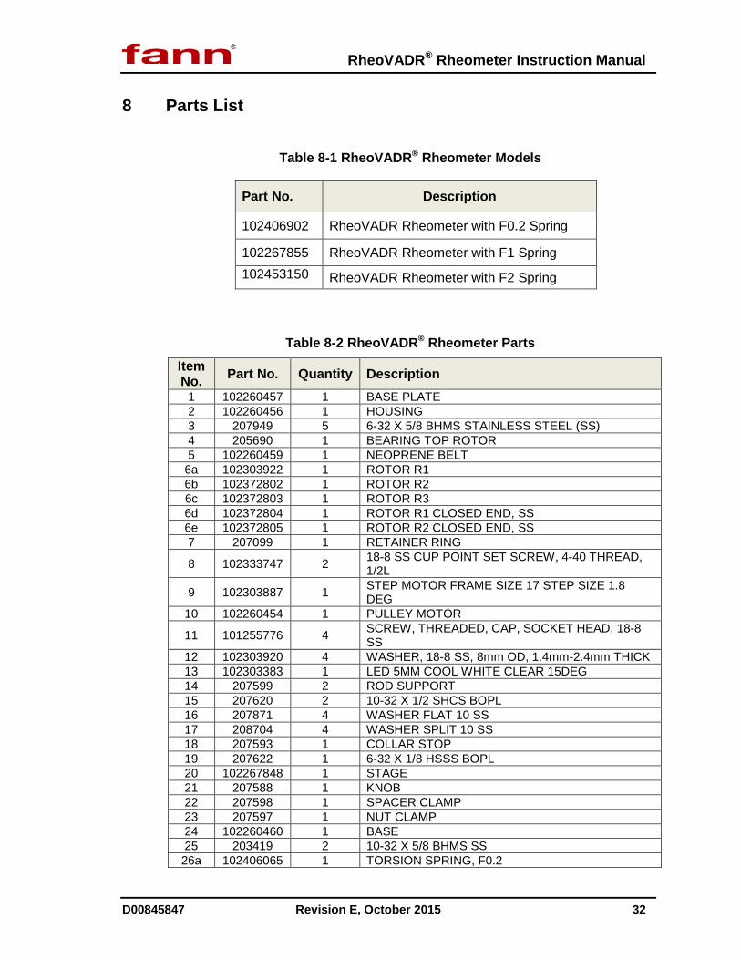
Table 8-1 RheoVADR® Rheometer Models
Part No. Description
102406902 RheoVADR Rheometer with F0.2 Spring
102267855 RheoVADR Rheometer with F1 Spring 102453150 RheoVADR Rheometer with F2 Spring
Table 8-2 RheoVADR® Rheometer Parts Item No. Part No. Quantity Description
1 102260457 1 BASE PLATE 2 102260456 1 HOUSING 3 207949 5 6-32 X 5/8 BHMS STAINLESS STEEL (SS) 4 205690 1 BEARING TOP ROTOR 5 102260459 1 NEOPRENE BELT
6a 102303922 1 ROTOR R1 6b 102372802 1 ROTOR R2 6c 102372803 1 ROTOR R3 6d 102372804 1 ROTOR R1 CLOSED END, SS 6e 102372805 1 ROTOR R2 CLOSED END, SS 7 207099 1 RETAINER RING
8 102333747 2 18-8 SS CUP POINT SET SCREW, 4-40 THREAD, 1/2L
9 102303887 1 STEP MOTOR FRAME SIZE 17 STEP SIZE 1.8 DEG
10 102260454 1 PULLEY MOTOR
11 101255776 4 SCREW, THREADED, CAP, SOCKET HEAD, 18-8 SS
12 102303920 4 WASHER, 18-8 SS, 8mm OD, 1.4mm-2.4mm THICK 13 102303383 1 LED 5MM COOL WHITE CLEAR 15DEG 14 207599 2 ROD SUPPORT 15 207620 2 10-32 X 1/2 SHCS BOPL 16 207871 4 WASHER FLAT 10 SS 17 208704 4 WASHER SPLIT 10 SS 18 207593 1 COLLAR STOP 19 207622 1 6-32 X 1/8 HSSS BOPL 20 102267848 1 STAGE 21 207588 1 KNOB 22 207598 1 SPACER CLAMP 23 207597 1 NUT CLAMP 24 102260460 1 BASE 25 203419 2 10-32 X 5/8 BHMS SS 26a 102406065 1 TORSION SPRING, F0.2
RheoVADR® Rheometer Instruction Manual
D00845847 Revision E, October 2015 33
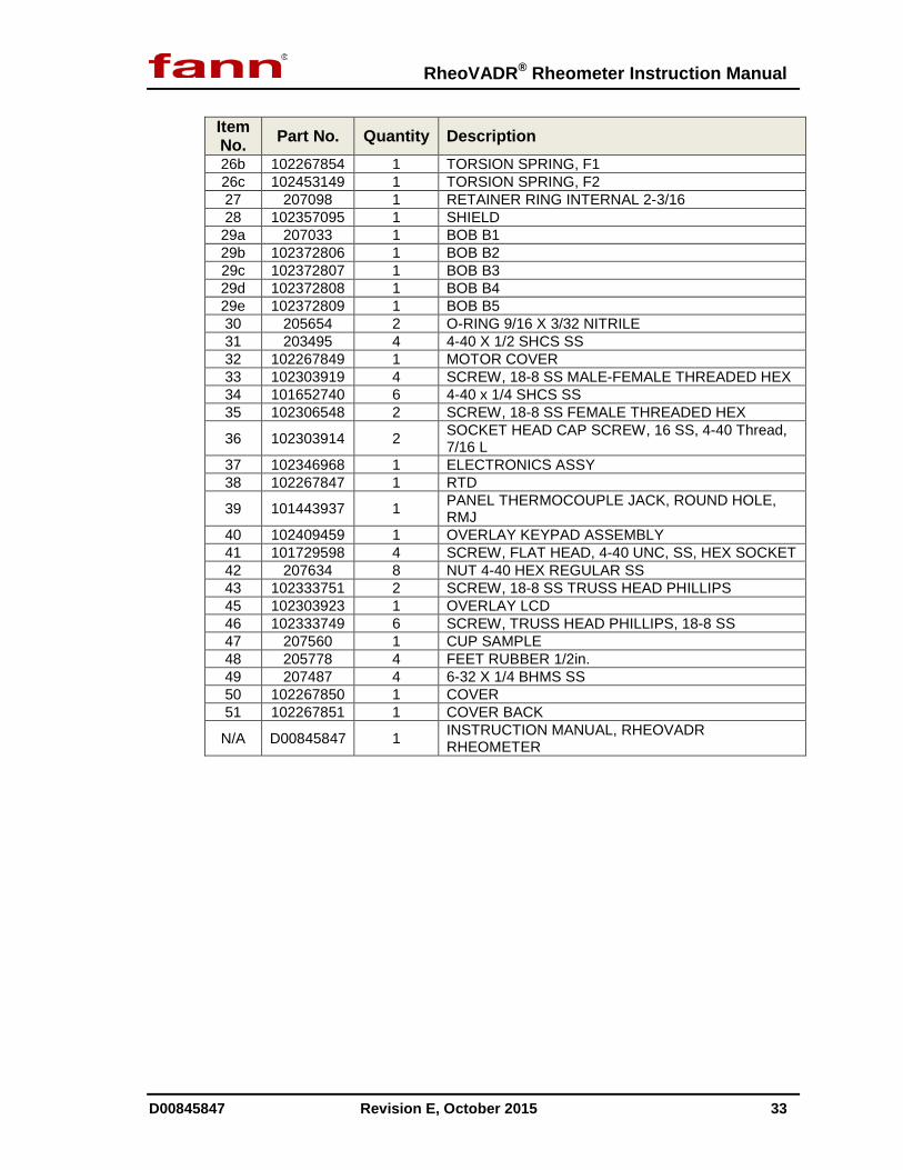
Item No. Part No. Quantity Description 26b 102267854 1 TORSION SPRING, F1 26c 102453149 1 TORSION SPRING, F2 27 207098 1 RETAINER RING INTERNAL 2-3/16 28 102357095 1 SHIELD 29a 207033 1 BOB B1 29b 102372806 1 BOB B2 29c 102372807 1 BOB B3 29d 102372808 1 BOB B4 29e 102372809 1 BOB B5 30 205654 2 O-RING 9/16 X 3/32 NITRILE 31 203495 4 4-40 X 1/2 SHCS SS 32 102267849 1 MOTOR COVER 33 102303919 4 SCREW, 18-8 SS MALE-FEMALE THREADED HEX 34 101652740 6 4-40 x 1/4 SHCS SS 35 102306548 2 SCREW, 18-8 SS FEMALE THREADED HEX
36 102303914 2 SOCKET HEAD CAP SCREW, 16 SS, 4-40 Thread, 7/16 L
37 102346968 1 ELECTRONICS ASSY 38 102267847 1 RTD
39 101443937 1 PANEL THERMOCOUPLE JACK, ROUND HOLE, RMJ
40 102409459 1 OVERLAY KEYPAD ASSEMBLY 41 101729598 4 SCREW, FLAT HEAD, 4-40 UNC, SS, HEX SOCKET 42 207634 8 NUT 4-40 HEX REGULAR SS 43 102333751 2 SCREW, 18-8 SS TRUSS HEAD PHILLIPS 45 102303923 1 OVERLAY LCD 46 102333749 6 SCREW, TRUSS HEAD PHILLIPS, 18-8 SS 47 207560 1 CUP SAMPLE 48 205778 4 FEET RUBBER 1/2in. 49 207487 4 6-32 X 1/4 BHMS SS 50 102267850 1 COVER 51 102267851 1 COVER BACK
N/A D00845847 1 INSTRUCTION MANUAL, RHEOVADR RHEOMETER

RheoVADR® Rheometer Instruction Manual
D00845847 Revision E, October 2015 34
Figure 8-1 RheoVADR® Rheometer Assembly, View 1

RheoVADR® Rheometer Instruction Manual
D00845847 Revision E, October 2015 35
Figure 8-2 RheoVADR® Rheometer Assembly, View 2

RheoVADR® Rheometer Instruction Manual
D00845847 Revision E, October 2015 36
9 Declaration of Conformity
RheoVADR® Rheometer Instruction Manual
D00845847 Revision E, October 2015 37
10 Warranty and Returns
10.1 Warranty
Fann Instrument Company warrants only title to the equipment, products and materials supplied and that the same are free from defects in workmanship and materials for one year from date of delivery. THERE ARE NO WARRANTIES, EXPRESS OR IMPLIED OF MERCHANTABILITY, FITNESS OR OTHERWISE BEYOND THOSE STATED IN THE IMMEDIATELY PRECEDING SENTENCE. Fann's sole liability and Customer's exclusive remedy in any cause of action (whether in contract, tort, breach of warranty or otherwise) arising out of the sale, lease or use of any equipment, products or materials is expressly limited to the replacement of such on their return to Fann or, at Fann's option, to the allowance to Customer of credit for the cost of such items. In no event shall Fann be liable for special, incidental, indirect, consequential or punitive damages. Notwithstanding any specification or description in its catalogs, literature or brochures of materials used in the manufacture of its products, Fann reserves the right to substitute other materials without notice. Fann does not warrant in any way equipment, products, and material not manufactured by Fann, and such will be sold only with the warranties, if any, that are given by the manufacturer thereof. Fann will only pass through to Customer the warranty granted to it by the manufacturer of such items.
10.2 Returns
For your protection, items being returned must be carefully packed to prevent damage in shipment and insured against possible damage or loss. Fann will not be responsible for damage resulting from careless or insufficient packing.
Before returning items for any reason, authorization must be obtained from Fann Instrument Company. When applying for authorization, please include information regarding the reason the items are to be returned.
Our correspondence address:
Fann Instrument Company P.O. Box 4350 Houston, Texas USA 77210
Telephone: 281-871-4482 Toll Free: 800-347-0450 FAX: 281-871-4446
Email [email protected]
Our shipping address:
Fann Instrument Company 14851 Milner Road, Gate 5 Houston, Texas USA 77032

RheoVADR® Rheometer Instruction Manual
D00845847 Revision E, October 2015 38
Appendix A API Profiles
Review the following table and notes to better understand the API Profiles.
In Stabilize or Peak mode only, if 1 point recording is specified, it will be the stabilized reading or Peak reading. If 2 points are specified, they will be recorded at the start and end of the step. If recording interval is specified, then recording will start immediately when step begins and continue recording at the specified rate at equal intervals. The fastest recording rate is every 0.1 sec.
In Continuous mode, if 1 point is specified, it will be recorded just before the end of that step time. If 2 points are specified, they will be recorded at the start and end of the step. If recording interval is specified, then recording will start immediately when step begins and continue recording at the specified rate at equal intervals. The fastest recording rate is every 0.1 sec.
Refer to the preceding table and notes that explain how data is captured and recorded.
Mode Description
Stabilize (S) The unit will run at specified Speed and Run Time, and then check for stability of readings. The dial is considered stabilized if it does not change more than 0.5 dial reading for 10 seconds. When stability is reached, it will proceed to the next step. However, the unit will continue indefinitely at that step if stability is not achieved.
Peak (P) The step runs for specified Run Time and the display shows the peak value of dial reading during this run time.
Continuous (C) The step runs for the specified Run Time and continues to the next step.

RheoVADR® Rheometer Instruction Manual
D00845847 Revision E, October 2015 39
Table A-1 API Six Speed & Gel Profile
Step Speed (rpm)
Run Time (s) Mode Number of Points
to Record* 1 600 10 S 1 2 300 10 S 1 3 200 10 S 1 4 100 10 S 1 5 6 10 S 1 6 3 10 S 1 7 600 10 C 2 8 0 10 P 2 9 3 10 P 0.1 sec interval 10 600 10 C 2 11 0 10 min C 2 12 3 10 P 0.1 sec interval
* Also shows recording rate. For example, Step 9, data points are recorded every 0.1 sec.
Table A-2 API PV/YP & Gel Profile
Step Speed (rpm)
RunTime (s) Mode Number of Points
to Record* 1 600 10 S 1
2 300 10 S 1
3 600 10 C 2
4 0 10 C 2
5 3 30 P 0.1 sec interval
6 600 10 C 2
7 0 10 min C 2
8 3 30 P 0.1 sec interval
* Also shows recording rate. For example, Step 5, data points are recorded every 0.1 sec.
Table A-3 API Gel Profile
Step Speed Run Time Mode Number of Points
RheoVADR® Rheometer Instruction Manual
D00845847 Revision E, October 2015 40
(rpm) (s) to Record* 1 600 10 C 2 2 0 10 C 2 3 3 10 P 0.1 sec interval 4 600 10 C 2 5 0 10 min C 2 6 3 10 P 0.1 sec interval
* Also shows recording rate. For example, Step 3, data points are recorded every 0.1 sec.
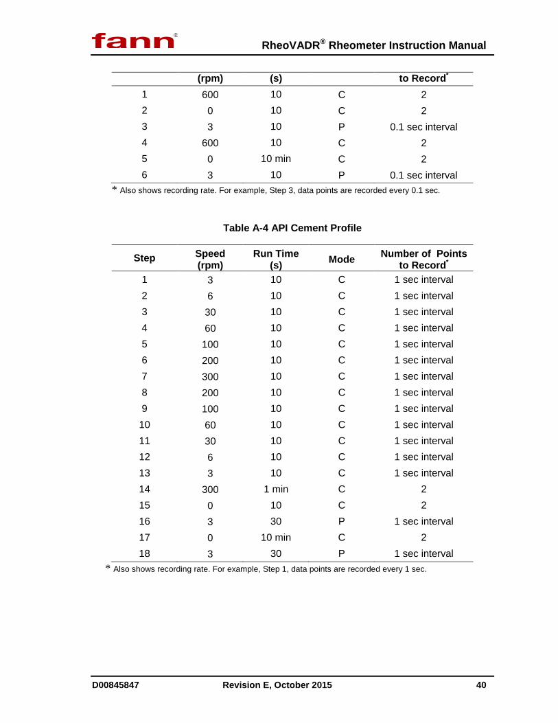
Table A-4 API Cement Profile
Step Speed (rpm)
Run Time (s) Mode Number of Points
to Record* 1 3 10 C 1 sec interval 2 6 10 C 1 sec interval 3 30 10 C 1 sec interval 4 60 10 C 1 sec interval 5 100 10 C 1 sec interval 6 200 10 C 1 sec interval 7 300 10 C 1 sec interval 8 200 10 C 1 sec interval 9 100 10 C 1 sec interval 10 60 10 C 1 sec interval 11 30 10 C 1 sec interval 12 6 10 C 1 sec interval 13 3 10 C 1 sec interval 14 300 1 min C 2 15 0 10 C 2 16 3 30 P 1 sec interval 17 0 10 min C 2 18 3 30 P 1 sec interval
* Also shows recording rate. For example, Step 1, data points are recorded every 1 sec.

RheoVADR® Rheometer Instruction Manual
D00845847 Revision E, October 2015 41
Appendix B Viscosity Calculations
To calculate Newtonian viscosities in centipoise, use the following equation:
ƞN = S x θ x f x C where,
S is the speed factor, = 300 / Test Speed
θ is the dial reading
f is the spring factor (Refer to Table B-2)
C is the rotor-bob factor (Refer to Table B-1 Rotor-Bob Factor (C))
ƞN is the Newtonian viscosity (cP)
Example: Using an R2-B1 combination at a speed of 600 rpm with an F5.0 spring, and a dial deflects to 189, the viscosity is
ƞN = 0.5 x 189 x 5 x 0.315 = 149 cP
Table B-1 Rotor-Bob Factor (C)
Rotor-Bob Combination
R-B Factor (C)
R1-B1 1.000 R1-B2 8.915 R1-B3 25.392 R1-B4 50.787 R1-B5 2.334 R2-B1 0.315 R2-B2 8.229 R2-B3 24.707 R2-B4 49.412 R2-B5 1.649 R3-B1 4.517 R3-B2 12.431 R3-B3 28.909 R3-B4 57.815 R3-B5 5.849

RheoVADR® Rheometer Instruction Manual
D00845847 Revision E, October 2015 42
Table B-2 Torsion Spring Specifications
Torsion Spring
Assembly
Torsion Spring Constant*
k1 (dyne/cm/degree
deflection)
Torsion Spring Factor
f
Maximum Shear Stress with B1
Bob (dyne/cm2)
Color Code
F0.2 77.2 0.2 307 Green
F0.5 193 0.5 766 Yellow
F1 386 1 1,533 Blue
F2 772 2 3,066 Red
F3 1,158 3 4,600 Purple
F4 1,544 4 6,132 White
F5 1,930 5 7,665 Black
F10 3,860 10 15,330 Orange
*With R1-B1 Combination
Related Documents