RH Series 726 www.idec.com Switches & Pilot Lights Display Lights Relays & Sockets Timers Terminal Blocks Circuit Breakers Relays & Sockets RH Series Compact Power Relays SPDT through 4PDT, 10A contacts Compact power type relays The RH series are miniature power relays with a large capacity. The RH relays feature 10A contact capacity as large as the RR series but in a miniature package. The compact size saves space. Part Number Selection Part Number Contact Model Blade Terminal PCB Terminal Coil Voltage Code (Standard Stock in bold) SPDT Basic RH1B-U RH1V2-U AC6V, AC12V, AC24V, AC110V, AC120V, AC220V, AC240V DC6V, DC12V, DC24V, DC48V, DC110V With Indicator RH1B-UL — With Check Button RH1B-UC — With Indicator and Check Button RH1B-ULC — Top Bracket Mounting RH1B-UT — With Diode (DC coil only) RH1B-UD RH1V2-UD DC6V, DC12V, DC24V, DC48V, DC110V With Indicator and Diode (DC coil only) RH1B-ULD — DC12V, DC24V, DC48V, DC110V DPDT Basic RH2B-U RH2V2-U AC6V, AC12V, AC24V, AC110-120V, AC220-240V DC6V, DC12V, DC24V, DC48V, DC100-110V With Indicator RH2B-UL RH2V2-UL With Check Button RH2B-UC — With Indicator and Check Button RH2B-ULC — Top Bracket Mounting RH2B-UT — With Diode (DC coil only) RH2B-UD RH2V2-UD DC6V, DC12V, DC24V, DC48V, DC100-110V With Indicator and Diode (DC coil only) RH2B-ULD — 3PDT Basic RH3B-U RH3V2-U AC6V, AC12V, AC24V, AC110V, AC120V, AC220V, AC240V DC6V, DC12V, DC24V, DC48V, DC110V With Indicator RH3B-UL RH3V2-UL With Check Button RH3B-UC — With Indicator and Check Button RH3B-ULC — Top Bracket Mounting RH3B-UT — With Diode (DC coil only) RH3B-D* RH3V2-D* DC6V, DC12V, DC24V, DC48V, DC110V With Indicator and Diode (DC coil only) RH3B-LD* — 4PDT Basic RH4B-U RH4V2-U AC6V, AC12V, AC24V, AC110V, AC120V, AC220V, AC240V DC6V, DC12V, DC24V, DC48V, DC110V With Indicator RH4B-UL RH4V2-UL With Check Button RH4B-UC — With Indicator and Check Button RH4B-ULC — Top Bracket Mounting RH4B-UT — With Diode (DC coil only) RH4B-UD RH4V2-UD DC6V, DC12V, DC24V, DC48V, DC110V With Indicator and Diode (DC coil only) RH4B-LD* — 1. *Carries no UL recognition mark. 2. PCB terminal relays are designed to mount directly to a circuit board without any socket. Ordering Information When ordering, specify the Part No. and coil voltage code: (example) RH3B-U AC120V Part No. Coil Voltage Code Courtesy of Steven Engineering, Inc.-230 Ryan Way, South San Francisco, CA 94080-6370-Main Office: (650) 588-9200-Outside Local Area: (800) 258-9200-www.stevenengineering.com

Welcome message from author
This document is posted to help you gain knowledge. Please leave a comment to let me know what you think about it! Share it to your friends and learn new things together.
Transcript
RH Series
726 www.idec.com
Sw
itch
es &
Pil
ot L
ight
sD
ispl
ay L
ight
sR
elay
s &
Soc
kets
Tim
ers
Term
inal
Blo
cks
Cir
cuit
Bre
aker
s
Relays & Sockets
RH Series Compact Power Relays
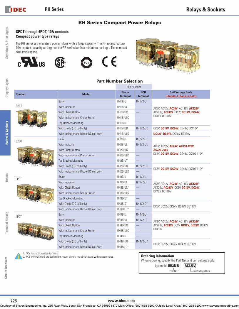
SPDT through 4PDT, 10A contacts Compact power type relays
The RH series are miniature power relays with a large capacity. The RH relays feature 10A contact capacity as large as the RR series but in a miniature package. The compact size saves space.
Part Number SelectionPart Number
Contact ModelBlade
TerminalPCB
TerminalCoil Voltage Code
(Standard Stock in bold)
SPDT
Basic RH1B-U RH1V2-U
AC6V, AC12V, AC24V, AC110V, AC120V, AC220V, AC240V DC6V, DC12V, DC24V, DC48V, DC110V
With Indicator RH1B-UL —
With Check Button RH1B-UC —
With Indicator and Check Button RH1B-ULC —
Top Bracket Mounting RH1B-UT —
With Diode (DC coil only) RH1B-UD RH1V2-UD DC6V, DC12V, DC24V, DC48V, DC110V
With Indicator and Diode (DC coil only) RH1B-ULD — DC12V, DC24V, DC48V, DC110V
DPDTBasic RH2B-U RH2V2-U
AC6V, AC12V, AC24V, AC110-120V, AC220-240V DC6V, DC12V, DC24V, DC48V, DC100-110V
With Indicator RH2B-UL RH2V2-UL
With Check Button RH2B-UC —
With Indicator and Check Button RH2B-ULC —
Top Bracket Mounting RH2B-UT —
With Diode (DC coil only) RH2B-UD RH2V2-UDDC6V, DC12V, DC24V, DC48V, DC100-110V
With Indicator and Diode (DC coil only) RH2B-ULD —
3PDTBasic RH3B-U RH3V2-U
AC6V, AC12V, AC24V, AC110V, AC120V, AC220V, AC240V DC6V, DC12V, DC24V, DC48V, DC110V
With Indicator RH3B-UL RH3V2-UL
With Check Button RH3B-UC —
With Indicator and Check Button RH3B-ULC —
Top Bracket Mounting RH3B-UT —
With Diode (DC coil only) RH3B-D* RH3V2-D*DC6V, DC12V, DC24V, DC48V, DC110V
With Indicator and Diode (DC coil only) RH3B-LD* —
4PDTBasic RH4B-U RH4V2-U
AC6V, AC12V, AC24V, AC110V, AC120V, AC220V, AC240V DC6V, DC12V, DC24V, DC48V, DC110V
With Indicator RH4B-UL RH4V2-UL
With Check Button RH4B-UC —
With Indicator and Check Button RH4B-ULC —
Top Bracket Mounting RH4B-UT —
With Diode (DC coil only) RH4B-UD RH4V2-UDDC6V, DC12V, DC24V, DC48V, DC110V
With Indicator and Diode (DC coil only) RH4B-LD* —
1. *Carries no UL recognition mark.2. PCB terminal relays are designed to mount directly to a circuit board without any socket. Ordering Information
When ordering, specify the Part No. and coil voltage code:
(example) RH3B-U AC120V
Part No. Coil Voltage Code
Courtesy of Steven Engineering, Inc.-230 Ryan Way, South San Francisco, CA 94080-6370-Main Office: (650) 588-9200-Outside Local Area: (800) 258-9200-www.stevenengineering.com

RH Series
727USA: 800-262-IDEC Canada: 888-317-IDEC
Sw
itches & P
ilot LightsD
isplay LightsR
elays & S
ocketsTim
ersTerm
inal Blocks
Circuit B
reakers
Relays & Sockets
Sockets (for Blade Terminal Models)
Relays Standard DIN Rail Mount 1 Finger-safe DIN Rail Mount 1 Through Panel Mount PCB Mount
RH1B SH1B-05 SH1B-O5C SH1B-51 SH1B-62
1. DIN Rail mount socket comes with two horseshoe clips. Do not use unless you plan to insert pullover wire spring. Replacement horseshoe clip part number is Y778-011.
RH2B SH2B-05 SH2B-05C SH2B-51 SH2B-62
RH3B SH3B-05 SH3B-05C SH3B-51 SH3B-62
RH4B SH4B-05 SH4B-05C SH4B-51 SH4B-62
Hold Down Springs & Clips
Appearance Description RelayFor DIN Mount Socket
For Through Panel & PCB Mount Socket
Min Order Qty
Pullover Wire Spring
RH1B SY2S-02F1 2
SY4S-51F1 10
2. Must use horseshoe clip when mounting in DIN mount socket. Replacement horseshoe clip part number is Y778-011.
3. Two required per relay.
RH2B SY4S-02F1 2
RH3B SH3B-05F1 2
RH4B SH4B-02F1 2
Leaf Spring (side latch)
RH1B, RH2B, RH3B, RH4B SFA-202 3 SFA-302 3
20
Leaf Spring (top latch)
RH1B, RH2B, RH3B, RH4B SFA-101 3 SFA-301 3
AC Coil Ratings
Voltage (V)
Rated Current (mA) ±15% at 20°C Coil Resistance (Ω)±10% at 20°C
Operation Characteristics(against rated values at 20ºC)AC 50Hz AC 60Hz
SPDT DPDT 3PDT 4PDT SPDT DPDT 3PDT 4PDT SPDT DPDT 3PDT 4PDTMax. Continuous Applied Voltage
Pickup Voltage
Dropout Voltage
6 170 240 330 387 150 200 280 330 330 9.4 6.4 5.4
110%80%
maximum30%
minimum
12 86 121 165 196 75 100 140 165 165 39.3 25.3 21.2
24 42 60.5 81 98 37 50 70 83 83 153 103 84.5
110 9.6 — 18.1 21.6 8.4 — 15.5 18.2 18.2 — 2,200 1,800
110-120 —9.4-10.8
— — — 8.0-9.2 — — — — — —
120 8.6 — 16.4 19.5 7.5 — 14.2 16.5 16.5 — 10,800 7,360
220 4.7 — 8.8 10.7 4.1 — 7.7 9.1 9.1 — 10,800 7,360
220-240 — 4.7-5.4 — — — 4.0-4.6 — — 18,820 — —
240 4.9 — 8.2 9.8 4.3 — 7.1 8.3 8.3 — 12,100 9,120
DC Coil Ratings
Voltage (V)
Rated Current (mA) ±15% at 20°CCoil Resistance (Ω)
±10% at 20°COperation Characteristics
(against rated values at 20ºC)
SPDT DPDT 3PDT 4PDT SPDT DPDT 3PDT 4PDTMax. Continuous Applied Voltage
Pickup Voltage
Dropout Voltage
6 128 150 240 250 47 40 25 24
110%80%
maximum10%
minimum
Standard coil voltages are in BOLD.
12 64 75 120 125 188 160 100 96
24 32 36.9 60 62 750 650 400 388
48 18 18.5 30 31 2,660 2,600 1,600 1,550
100-110 — 8.2-9.0 — — — 12,250 — —
110 8 — 12.8 15 13,800 — 8,600 7,340
Courtesy of Steven Engineering, Inc.-230 Ryan Way, South San Francisco, CA 94080-6370-Main Office: (650) 588-9200-Outside Local Area: (800) 258-9200-www.stevenengineering.com

RH Series
728 www.idec.com
Sw
itch
es &
Pil
ot L
ight
sD
ispl
ay L
ight
sR
elay
s &
Soc
kets
Tim
ers
Term
inal
Blo
cks
Cir
cuit
Bre
aker
s
Relays & Sockets
Contact Ratings
Maximum Contact Capacity
ModelContinuous
Current
Allowable Contact Power Rated Load
Resistive Load
Inductive Load
Voltage (V)
Res. Load
Ind. Load
SPDT 10A1540VA300W
990VA210W
110 AC 10A 7A
220 AC 7A 4.5A
30 DC 10A 7A
DPDT3PDT4PDT
10A1650VA300W
1100VA225W
110 AC 10A 7.5A
220 AC 7.5A 5A
30 DC 10A 7.5A
Note: Inductive load for the rated load — cos ø = 0.3, L/R = 7 ms
TÜV Ratings
Voltage RH1 RH2 RH3 RH4
240V AC 10A 10A 7.5A 7.5A
30V DC 10A 10A 10A 10A
AC: cos ø = 1.0, DC: L/R = 0 ms
Socket Specifi cations
Sockets Terminal Electrical Rating Wire Size Torque
DIN Rail Mount Sockets
SH1B-05(Coil) M3 screws(contact) M3.5 screws with captive wire clamp
250V, 10A Maximum up to 2–#12AWG5.5 - 9 in•lbs9 - 11.5 in•lbs
SH2B-05SH3B-05SH4B-05
M3.5 screws with captive wire clamp 300V, 10A Maximum up to 2–#12AWG 9 - 11.5 in•lbs
Finger-safe DIN Rail Mount
SH1B-05C(coil) M3 screws(contact) M3.5 screws with captive wire clamp, fi ngersafe
250V, 10A Maximum up to 2–#12AWG5.5 - 9 in•lbs9 - 11.5 in•lbs
SH2B-05CSH3B-05CSH4B-05C
M3.5 screws with captive wire clamp, fi ngersafe 300V, 10A Maximum up to 2–#12AWG 9 - 11.5 in•lbs
ThroughPanel Mount Socket
SH1B-51SH2B-51SH3B-51SH4B-51
Solder 300V, 10A — —
PCB Mount Socket
SH1B-62 PCB mount 250V, 10A — —
SH2B-62SH3B-62SH4B-62
PCB mount 300V, 10A — —
Accessories
Description Appearance Use with Part No. Remarks
Aluminum DIN Rail (1 meter length)
All DIN rail sockets BNDN1000
IDEC offers a low-profi le DIN rail (BNDN1000). The BNDN1000 is de-signed to accommodate DIN mount sockets. Made of durable extruded aluminum, the BNDN1000 measures 0.413 (10.5mm) in height and 1.37 (35mm) in width (DIN standard). Standard length is 39” (1,000mm).
DIN Rail End Stop
DIN rail BNL5 9.1 mm wide.
Replacement Hold-Down Spring Anchor
DIN mount sockets and hold down springs.
Y778-011For use on DIN rail mount socket when using pullover wire hold down spring. 2 pieces included with each socket.
UL Ratings
Voltage
Resistive General Use Horse Power Rating
RH1RH2
RH3 RH4RH1RH2
RH3 RH4RH1RH2
RH3 RH4
240V AC 10A 7.5A 7.5A 7A 6.5A 5A 1/3 HP 1/3 HP —
120V AC — 10A 10A — 7.5A 7.5A 1/6 HP 1/6 HP —
30V DC 10A 10A — 7A — — — — —
28V DC — — 10A — — — — — —
CSA Ratings
VoltageResistive General Use
Horse Power Rating
RH1 RH2 RH3 RH4 RH1 RH2 RH3 RH4 RH1, 2, 3
240V AC 10A 10A — 7.5A 7A 7A 7A 5A 1/3 HP
120V AC 10A 10A 10A 10A 7.5A 7.5A — 7.5A 1/6 HP
30V DC 10A 10A 10A 10A 7A 7.5A — — —
Courtesy of Steven Engineering, Inc.-230 Ryan Way, South San Francisco, CA 94080-6370-Main Office: (650) 588-9200-Outside Local Area: (800) 258-9200-www.stevenengineering.com
RH Series
729USA: 800-262-IDEC Canada: 888-317-IDEC
Sw
itches & P
ilot LightsD
isplay LightsR
elays & S
ocketsTim
ersTerm
inal Blocks
Circuit B
reakers
Relays & Sockets
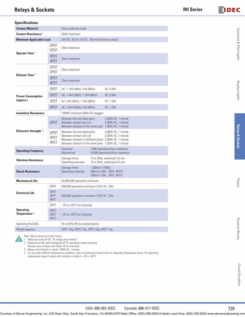
Specifi cations
Contact Material Silver cadmium oxide
Contact Resistance 1 50mΩ maximum
Minimum Applicable Load 24V DC, 30 mA; 5V DC, 100 mA (reference value)
Operate Time 2
SPDTDPDT
20ms maximum
3PDT4PDT
25ms maximum
Release Time 2
SPDTDPDT
20ms maximum
3PDT4PDT
25ms maximum
Power Consumption (approx.)
SPDT AC: 1.1VA (50Hz), 1VA (60Hz) DC: 0.8W
DPDT AC: 1.4VA (50Hz), 1.2VA (60Hz) DC: 0.9W
3PDT AC: 2VA (50Hz), 1.7VA (60Hz) DC: 1.5W
4PDT AC: 2.5VA (50Hz), 2VA (60Hz) DC: 1.5W
Insulation Resistance 100MΩ minimum (500V DC megger)
Dielectric Strength 3
SPDTBetween live and dead parts: 2,000V AC, 1 minuteBetween contact and coil: 2,000V AC, 1 minuteBetween contacts of the same pole: 1,000V AC, 1 minute
DPDT3PDT4PDT
Between live and dead parts: 2,000V AC, 1 minuteBetween contact and coil: 2,000V AC, 1 minuteBetween contacts of different poles: 2,000V AC, 1 minuteBetween contacts of the same pole: 1,000V AC, 1 minute
Operating FrequencyElectrical: 1,800 operations/hour maximumMechanical: 18,000 operations/hour maximum
Vibration ResistanceDamage limits: 10 to 55Hz, amplitude 0.5 mmOperating extremes: 10 to 55Hz, amplitude 0.5 mm
Shock ResistanceDamage limits: 1,000m/s2 (100G)Operating extremes: 200m/s2 (20G - SPDT, DPDT) 100m/s2 (10G - 3PDT, 4PDT)
Mechanical Life 50,000,000 operations minimum
Electrical Life
DPDT 500,000 operations minimum (120V AC, 10A)
SPDT3PDT4PDT
200,000 operations minimum (120V AC, 10A)
Operating Temperature 4
SPDT –25 to +50°C (no freezing)
DPDT3PDT4PDT
–25 to +40°C (no freezing)
Operating Humidity 45 to 85% RH (no condensation)
Weight (approx.) SPDT: 24g, DPDT: 37g, 3PDT: 50g, 4PDT: 74g
Note: Above values are initial values.1. Measured using 5V DC, 1A voltage drop method2. Measured at the rated voltage (at 20°C), excluding contact bouncing
Release time of relays with diode: 40 ms maximum3. Relays with indicator or diode: 1000V AC, 1 minute 4. For use under different temperature conditions, refer to Continuous Load Current vs. Operating Temperature Curve. The operating
temperature range of relays with indicator or diode is –25 to +40°C.
Courtesy of Steven Engineering, Inc.-230 Ryan Way, South San Francisco, CA 94080-6370-Main Office: (650) 588-9200-Outside Local Area: (800) 258-9200-www.stevenengineering.com

RH Series
730 www.idec.com
Sw
itch
es &
Pil
ot L
ight
sD
ispl
ay L
ight
sR
elay
s &
Soc
kets
Tim
ers
Term
inal
Blo
cks
Cir
cuit
Bre
aker
s
Relays & Sockets
Characteristics (Reference Data)
Electrical Life Curves
AC Load DC Load
1 3 5 7 92 4 6 8 10
50
20
10
100
500
1000
Load Current (A)
120V AC resistive
240V AC inductive120V AC inductive 240V AC resistive
Life
(×
10,0
00 o
pera
tions
)
(RH1)
1 3 5 7 92 4 6 8 10
50
20
10
100
500
1000
Load Current (A)
30V DC resistive
100V DC inductive
30V DC inductive
100V DC resistiveLife
(×
10,0
00 o
pera
tions
)
(RH1)
1 3 5 7 92 4 6 8 10
50
20
10
100
500
1000
Load Current (A)
120V AC resistive
240V AC inductive120V AC inductive240V AC resistive
Life
(×
10,0
00 o
pera
tions
)
(RH2)
1 3 5 7 92 4 6 8 10
50
20
10
100
500
1000
Load Current (A)
30V DC resistive
100V DC inductive
30V DCinductive100V DC resistiveLi
fe (
× 10
,000
ope
ratio
ns)
(RH2)
1 3 5 7 92 4 6 8 10
50
20
10
100
500
1000
Load Current (A)
120V AC resistive
240V AC inductive
120V AC inductive240V AC resistive
Life
(×
10,0
00 o
pera
tions
)
(RH3/RH4)
1 3 5 7 92 4 6 8 10
50
20
10
100
500
1000
Load Current (A)
30V DC resistive
100V DC inductive
30V DC inductive
100V DC resistive
Life
(×
10,0
00 o
pera
tions
)
(RH3/RH4)
Maximum Switching Capacity
1 5
0.5
1.0
5.0
10.0
10 100 200 300500.1
Load Voltage (V)
Load
Cur
rent
(A
)
DC inductive
DC resistive
AC inductive
AC resistive
(RH1)
1 5
0.5
1.0
5.0
10.0
10 100 200 300500.1
DC inductive
DC resistive
AC resistive
AC inductive
Load Voltage (V)
Load
Cur
rent
(A
)
(RH2/RH3/RH4)
Courtesy of Steven Engineering, Inc.-230 Ryan Way, South San Francisco, CA 94080-6370-Main Office: (650) 588-9200-Outside Local Area: (800) 258-9200-www.stevenengineering.com
RH Series
731USA: 800-262-IDEC Canada: 888-317-IDEC
Sw
itches & P
ilot LightsD
isplay LightsR
elays & S
ocketsTim
ersTerm
inal Blocks
Circuit B
reakers
Relays & Sockets
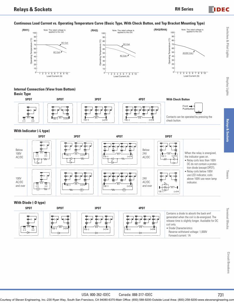
Continuous Load Current vs. Operating Temperature Curve (Basic Type, With Check Button, and Top Bracket Mounting Type)
10
10
20
30
40
50
60
70
80
90
100
3 5 7 92 4 6 8 10
DC Coil
AC Coil
Note: The rated voltage is applied to the coil.
Load Current (A)
Ope
ratin
g Te
mpe
ratu
re (
C)
(RH1)
10
10
20
30
40
50
60
70
80
90
100
3 5 7 92 4 6 8 10
DC Coil
AC Coil
Load Current (A)
Ope
ratin
g Te
mpe
ratu
re (
C)
Note: The rated voltage is applied to the coil.
(RH2)
10
10
20
30
40
50
60
70
80
90
100
3 5 7 92 4 6 8 10
AC/DC Coil
Load Current (A)
Ope
ratin
g Te
mpe
ratu
re (
C)
Note: The rated voltage is applied to the coil.
(RH3/RH4)
Internal Connection (View from Bottom)Basic Type
SPDT DPDT 3PDT 4PDT With Check Button
FrontPushbutton
Contacts can be operated by pressing the check button.
1
5
13 14
9
( – ) ( + )
1
5
13 14
9
4
8
12
( – ) ( + )
1
5
13 14
9
4
8
2
6
1210
( – ) ( + )
1
5
13 14
9
2
6
10
3
7
11
4
8
12
( – ) ( + )
With Indicator (-L type)
SPDT 3PDT 4PDT DPDT
Below 100V AC/DC
1
5
13 14
9
( – ) ( + )
1
5
9
4
8
2
6
1210
13 14( – ) ( + )
1
5
13 14
9
2
6
10
3
7
11
4
8
12
( – ) ( + )
Below 24V AC/DC
1
5
13 14
9
4
8
12
( – ) ( + )When the relay is energized, the indicator goes on.
Relay coils less than 100V DC do not contain a protec-tion diode (except DPDT).Relay coils below 100V use LED indicator, coils above 100V use neon lamp indicator.
•
•
100V AC/DC and over
1
5
13 14
9
( – ) ( + )
1
5
9
4
8
2
6
1210
13 14( – ) ( + ) ( – ) ( + )
1
5
13 14
9
2
6
10
3
7
11
4
8
1224V AC/DC and over
1
5
13 14
9
4
8
12
( – ) ( + )
With Diode (-D type)
SPDT DPDT 3PDT 4PDT
1
5
13 14
9
( – ) ( + )
1
5
13 14
9
4
8
12
( – ) ( + )
1
5
13 14
9
2
6
10
4
8
12
( – ) ( + )
1
5
13 14
9
2
6
10
3
7
11
4
8
12
( – ) ( + )
Contains a diode to absorb the back emf generated when the coil is de-energized. The release time is slightly longer. Available for DC coil only.
Diode CharacteristicsReverse withstand voltage: 1,000VForward current: 1A
•
Courtesy of Steven Engineering, Inc.-230 Ryan Way, South San Francisco, CA 94080-6370-Main Office: (650) 588-9200-Outside Local Area: (800) 258-9200-www.stevenengineering.com
RH Series
732 www.idec.com
Sw
itch
es &
Pil
ot L
ight
sD
ispl
ay L
ight
sR
elay
s &
Soc
kets
Tim
ers
Term
inal
Blo
cks
Cir
cuit
Bre
aker
s
Relays & Sockets
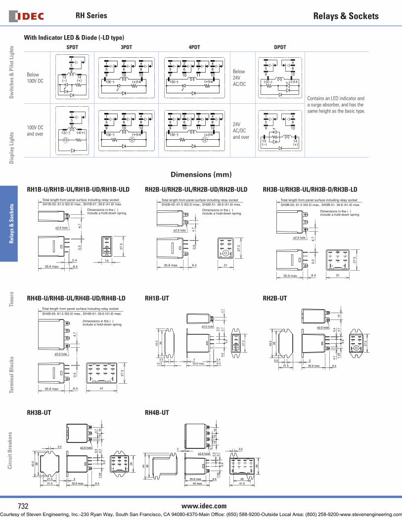
With Indicator LED & Diode (-LD type)
SPDT 3PDT 4PDT DPDT
Below 100V DC
1
5
13 14
9
( – ) ( + )
1
5
13 14
9
2
6
10
4
8
12
( – ) ( + )
1
5
13 14
9
2
6
10
3
7
11
4
8
12
( – ) ( + )
Below 24V AC/DC
1
5
13 14
9
4
8
12
( – ) ( + )
Contains an LED indicator and a surge absorber, and has the same height as the basic type.
100V DC and over
1
5
13 14
9
( – ) ( + )
1
5
13 14
9
2
6
10
4
8
12
( – ) ( + )
1
5
13 14
9
2
6
10
3
7
11
4
8
12
( – ) ( + )
24V AC/DC and over
1
5
13 14
9
4
8
12
( – ) ( + )
Dimensions (mm)
RH1B-U/RH1B-UL/RH1B-UD/RH1B-ULD RH2B-U/RH2B-UL/RH2B-UD/RH2B-ULD RH3B-U/RH3B-UL/RH3B-D/RH3B-LD
13
1
5
9
14
4.7
0.5
6.4
5.4 14
27.5
SH1B-05: 61.5 (63.5) max., SH1B-51: 39.6 (41.6) max.
35.6 max.
Total length from panel surface including relay socket
Dimensions in the ( )include a hold-down spring.
ø2.6 hole
1 4
5 8
9 12
13 14
6.4 21
27.5
4.7
0.5
SH2B-05: 61.5 (63.5) max., SH2B-51: 39.6 (41.6) max.
35.6 max.
Total length from panel surface including relay socket
Dimensions in the ( )include a hold-down spring.
ø2.6 hole
13 14
1 2 4
865
9 10 11
4.7
0.5
27.5
6.4 31
SH3B-05: 61.5 (63.5) max., SH3B-51: 39.6 (41.6) max.
35.6 max.
Total length from panel surface including relay socket
Dimensions in the ( )include a hold-down spring.
ø2.6 hole
RH4B-U/RH4B-UL/RH4B-UD/RH4B-LD RH1B-UT RH2B-UT
1 2 3 4
7 865
9 10 11 12
13 14
6.4 41
4.7
0.5 27
.5
SH4B-05: 61.5 (63.5) max., SH4B-51: 39.6 (41.6) max.
35.6 max.
Total length from panel surface including relay socket
Dimensions in the ( )include a hold-down spring.
ø2.6 hole
ø2.6 hole
13
1
5
9
14
3.514.5 35.6 max. 6.4
5.42
3843.2
27.5
6.6
5.9
4.7
0.5
4.7
ø2.6 hole
1 4
5 8
9 12
13 14
3.5
21.5
2
35.6 max. 6.4
3843.2
27.5
4.7
5.9
7.25
0.5
4.7
10
RH3B-UT RH4B-UT
ø2.6 hole
13 14
1 2 4
865
9 10 12
21.5
31.5 35.6 max. 6.4
3.5
3843.2
28
1010
4.7
2
4.7
5.9
7.25
0.5
ø2.6 hole
1010
104.
7
2
35.6 max. 6.4
42 max.
13
12
14
1 2 3 4
7 865
9 10 11
28
41.5
28
3.5
3844
4.7
5.9
7.25
0.5
Courtesy of Steven Engineering, Inc.-230 Ryan Way, South San Francisco, CA 94080-6370-Main Office: (650) 588-9200-Outside Local Area: (800) 258-9200-www.stevenengineering.com

RH Series
733USA: 800-262-IDEC Canada: 888-317-IDEC
Sw
itches & P
ilot LightsD
isplay LightsR
elays & S
ocketsTim
ersTerm
inal Blocks
Circuit B
reakers
Relays & Sockets
Dimensions con’t (mm)
RH1V2-U/RH1V2-UD RH2V2-U/RH2V2-UL/RH2V2-UD
13
1
5
9
14
35.6 max. 4.6
0.5
27.5
14
3-ø2.4 holes2-ø2 holes
4.4
7.15
6.6 12
.54.
7
0.5
1.5
2
8-ø2.4 holes
10
14.2
7.8
7.25
13.1
54.
7
1413
1 4
5 8
9 12
35.6 max. 4.6
27.5
5
20.
5
0.5
2
0.5
21
RH3V2-U/RH3V2-UL/RH3V2-D RH4V2-U/RH4V2-UL/RH4V2-UD
13 14
1 2 4
865
9 10 11
35.6 max. 4.6
310.5
0.5
2
27.5
11-ø2.4 holes 10 10
7.8
7.25
13.1
54.
7
1 2 3 4
7 865
9 10 11 12
13 14
20.
5
35.6 max. 4.6
0.5 41
27.5
14-ø2.4 holes
7.8
7.25
13.1
54.
710
30
Standard DIN Rail Mount Sockets
SH1B-05 SH2B-05
5
1
9
14 13
Terminal Arrangement
17
4.2
672.
5 20
16
8
7.9 max.25
47
18
14.5
4.4 max.
5.5 min.M3 TerminalScrew
M3.5 TerminalScrew
31.5
DIN Rail(BNDN)
(For terminals 1, 5, and 9)
ø3.6 min.
16
2-ø4.2 Mounting Holes(or M4 Tapped Holes)
5.9 max.
4 max.
4.8 min.
(For terminals 13 and 14)
ø3.2 min.(Top View)
22
4.2
672.
5
8
26
25
47
18
14.526
30
M3.5 TerminalScrew
31.5
DIN Rail(BNDN)
8
4
5
1
12
14
9
13
Terminal Arrangement2-ø4.2 Mounting Holes(or M4 Tapped Holes)
7.9 max.
4.4 max. 5.5 min.
ø3.6 min.
(Top View)
SH3B-05 SH4B-05
36
25
32
4.2
672.
5
47
18
14.5
8
ø3.6 min.7.9 max.
4.4 max. 5.5 min.
36
40
M3.5 TerminalScrew
31.5
DIN Rail(BNDN)
5
1
12
14
10
13
8
4
6
2
9
Terminal Arrangement
2-ø4.2 Mounting Holes(or M4 Tapped Holes)
(Top View)
46
25
42
4.2
672.
5
47
18
14.5
8
46
50
M3.5 TerminalScrew
31.5
DIN Rail(BNDN)
5
1
9
13
10
14
8
4
7
3
6
2
12 11
Terminal Arrangement2-ø4.2 Mounting Holes(or M4 Tapped Holes)
ø3.6 min.7.9 max.
4.4 max. 5.5 min.
(Top View)
Courtesy of Steven Engineering, Inc.-230 Ryan Way, South San Francisco, CA 94080-6370-Main Office: (650) 588-9200-Outside Local Area: (800) 258-9200-www.stevenengineering.com

RH Series
734 www.idec.com
Sw
itch
es &
Pil
ot L
ight
sD
ispl
ay L
ight
sR
elay
s &
Soc
kets
Tim
ers
Term
inal
Blo
cks
Cir
cuit
Bre
aker
s
Relays & Sockets
Dimensions con’t (mm)
Finger-safe DIN Rail Mount Sockets
SH1B-05C SH2B-05C
ø5
16
25
1.7
29.5
18.7
4817
7
69
20
4.2
16
M3.5 Terminal Screw
M3 TerminalScrew
36
2-ø4.2 Mounting Holes(or M4 Tapped Holes)
5
1
9
14 13
Terminal ArrangementDIN Rail(BNDN)
(Top View)Ring terminals cannot be used.
ø5
1.7
69
4.2
22
7
30
26
M3.5 TerminalScrew
8
4
5
1
12
14
9
13
Terminal Arrangement25
29.5
18.7
49
DIN Rail (BNDN)
36
26
2-ø4.2 Mounting Holes(or M4 Tapped Holes)
(Top View)Ring terminals cannot be used.
SH3B-05C SH4B-05C
1.7
32
69
4.2
7
40
36
ø5
M3.5 TerminalScrew
5
1
12
14
10
13
8
4
6
2
9
Terminal Arrangement
36
2-ø4.2 Mounting Holes(or M4 Tapped Holes)
25
29.5
18.7
49
36DIN Rail(BNDN)
(Top View)Ring terminals cannot be used.
ø5
25
4.2
1.7
69
46
42
7
18.7
29.550
49
5
1
9
13
10
14
8
4
7
3
6
2
12 11
46
36
DIN Rail(BNDN) Terminal Arrangement
2-ø4.2 Mounting Holes(or M4 Tapped Holes)
Ring terminals cannot be used.
(Top View)
Through Panel Mount Socket
SH1B-51 SH2B-51
3
11
18.7
18
31
2.4
12.2
0.3
25.4
3.5
Panel Thickness:1 to 2
13
159
(Bottom View)
14
Terminal Arrangement
25.6
0+0.5
+0.
20
∗ 10.4 min. when using hold-down springs
5.4
min
.∗
N: No. of sockets mounted
[18 (N–1) + 12.4]
3
11
18.7
27
31
0.3
25.4
21.2
3.5
Panel Thickness:1 to 2
13
159
4
128
14
Terminal Arrangement
25.6
+0.
20
+0.50
∗ 10.4 min. when using hold-down springs
5.4
min
.∗ N: No. of sockets mounted
[27 (N–1) + 21.4]
(Bottom View)
SH3B-51 SH4B-51
3
11
18.7
31
0.3
25.4
30.2
3.5
36
Panel Thickness:1 to 2 Terminal Arrangement
13
159
2
106
14
4
128
25.6
+0.
20
+0.50
∗ 10.4 min. when using hold-down springs
5.4
min
.∗ N: No. of sockets mounted
[36 (N–1) + 30.4]
(Bottom View)
3
11
18.7
31
0.3
25.4
39.2
45
3.5
Panel Thickness:1 to 2
13
159
3
117
14
4
128
2
106
Terminal Arrangement
25.6
+0.
20
+0.50
∗ 10.4 min. when using hold-down springs
5.4
min
.∗
N: No. of sockets mounted
[45 (N–1) + 39.4]
(Bottom View)
Courtesy of Steven Engineering, Inc.-230 Ryan Way, South San Francisco, CA 94080-6370-Main Office: (650) 588-9200-Outside Local Area: (800) 258-9200-www.stevenengineering.com

RH Series
735USA: 800-262-IDEC Canada: 888-317-IDEC
Sw
itches & P
ilot LightsD
isplay LightsR
elays & S
ocketsTim
ersTerm
inal Blocks
Circuit B
reakers
Relays & Sockets
Dimensions con’t (mm)
PCB Mount Sockets
SH1B-62 SH2B-62
3
11
15
18
31
0.3
25.4
12.2
1.52
13
159
14
Terminal Arrangement 18 min.
2-ø2 holes
3-ø2.4 holes
(Tolerance 0.1)36 min. when using
hold-down springs
31 m
in.
4.7
4.4
6.8
5.95
6.95
11.8
5
(Bottom View)3
11
15
0.3
25.4
21.2
29
2
13
159
4
128
14
Terminal Arrangement
∗ 34 min. when using hold-down springs
21.5 min.
8-ø2.4 holes
(Tolerance ±0.1)
29
min
.∗4.
7
2.85
5.65
12.5
15.5
10
6.6
(Bottom View)
SH3B-62 SH4B-62
3
11
15
31
0.3
25.4
30.2
36
2
13
159
2
106
14
4
128
Terminal Arrangement
∗ 36 min. when using hold-down springs
6.6
36 min.
11-ø2.4 holes
(Tolerance ±0.1)
31
min
.∗6.
6512
.5
21.3
10 10
7.35
4.7
(Bottom View)3
11
15
31
0.3
25.4
39.2
45
2
13
159
3
117
14
4
128
2
106
Terminal Arrangement 45 min.
14-ø2.4 holes
(Tolerance ±0.1)∗ 36 min. when using hold-down springs
31 m
in.∗
4.
7
31.3
6.85
6.6
6.65
12.5
10 10 10
(Bottom View)
Courtesy of Steven Engineering, Inc.-230 Ryan Way, South San Francisco, CA 94080-6370-Main Office: (650) 588-9200-Outside Local Area: (800) 258-9200-www.stevenengineering.com
Related Documents


