Path: Home => AVR-EN => Applications => RGB BCD watch m16 AVR applications RGB BCD watch with AT- mega16 Hardware, Mounting, Application and Soft- ware for the BCD watch RGB BCD watch with ATmega16 ... as contrast to decimal or ordinary digital watches, here with several colors to select from. 1. Properties 2. Hardware 3. mounting 4. Software 1 Properties der RGB-Uhr mit ATmega16 The hardware properties of the described BCD watch: • BCD encoded: Hours, minutes and seconds as binary encoded digits, One, two, four, eight, ten, twenty and forty with one single LED • 20 RGB leds show the time in Hours:Minutes:Seconds as binary digits in four differ- ent colors (configurable by software): 1. Hours between 1 and 5, Minutes and Seconds between 1 to 14: blue 2. Hours between 6 and 11, Minutes and Seconds between 15 to 29: green 3. Hours between 12 and 17, Minutes and Seconds between 30 to 44: red 4. Hours between 18 and 23, Minutes and Seconds between 45 to 59: violet • Advantages: such a watch cannot be easily read by anyone, readable only by digital natives and those who are deep into binary math, lots of colors increase the singu- larity of the bedside cabinet: not only red or green but up to four different colors in- crease design properties, very strong light display that can also used if your bed is located in a corn field on a nice and shiny summer day, replaces the slightly glim- ming yellow glow of high-voltage diverse electronic devices by colorful appearance during romantic hours with low voltage glow • Can be regulated in intensity with a simple potentiometer • Crystal watch, therefore very exact time, can be adjusted in a convenient and fast procedure by use of two keys and the potentiometer (no forward/backward strug- gling like with other watches), • Very low power consumption: less than 1 kWh for a whole year • Well documented free assembler source code, simply modifiable for other color combinations, clock frequencies and adaptable to other AVR controller types • Various diagnostic options in the source code enable and ease hardware debugging • Free documentation with source code and all calculation sheets and drawings • Simple re-programming within the running system via the built-in ISP6 interface, quick changes for color settings possible Page top Properties Hardware mounting Software Page 1 of 34

Welcome message from author
This document is posted to help you gain knowledge. Please leave a comment to let me know what you think about it! Share it to your friends and learn new things together.
Transcript

Path: Home => AVR-EN => Applications => RGB BCD watch m16
AVR applications
RGB BCD watch with AT-mega16
Hardware, Mounting,Application and Soft-
ware for the BCD watch
RGB BCD watch with ATmega16... as contrast to decimal or ordinary digital watches, here with several colors to selectfrom.
1. Properties 2. Hardware 3. mounting 4. Software
1 Properties der RGB-Uhr mit ATmega16The hardware properties of the described BCD watch:
• BCD encoded: Hours, minutes and seconds as binary encoded digits, One, two,four, eight, ten, twenty and forty with one single LED
• 20 RGB leds show the time in Hours:Minutes:Seconds as binary digits in four differ-ent colors (configurable by software):
1. Hours between 1 and 5, Minutes and Seconds between 1 to 14: blue 2. Hours between 6 and 11, Minutes and Seconds between 15 to 29: green 3. Hours between 12 and 17, Minutes and Seconds between 30 to 44: red 4. Hours between 18 and 23, Minutes and Seconds between 45 to 59: violet
• Advantages: such a watch cannot be easily read by anyone, readable only by digitalnatives and those who are deep into binary math, lots of colors increase the singu-larity of the bedside cabinet: not only red or green but up to four different colors in-crease design properties, very strong light display that can also used if your bed islocated in a corn field on a nice and shiny summer day, replaces the slightly glim-ming yellow glow of high-voltage diverse electronic devices by colorful appearanceduring romantic hours with low voltage glow
• Can be regulated in intensity with a simple potentiometer • Crystal watch, therefore very exact time, can be adjusted in a convenient and fast
procedure by use of two keys and the potentiometer (no forward/backward strug-gling like with other watches),
• Very low power consumption: less than 1 kWh for a whole year • Well documented free assembler source code, simply modifiable for other color
combinations, clock frequencies and adaptable to other AVR controller types • Various diagnostic options in the source code enable and ease hardware debugging • Free documentation with source code and all calculation sheets and drawings • Simple re-programming within the running system via the built-in ISP6 interface,
quick changes for color settings possible
Page top Properties Hardware mounting Software
Page 1 of 34
2 Hardware
2.1 Display part
This is the display part of the watch. It consists of 20 RGB leds with common anode andtwo 16-pin socket terminal strips that connect the display part to the controller part.
Driving the leds is organized using multiplexing. Each one third of the time the hours,minutes and seconds are active. Therefore the anodes of two digits are all connected andare tied with a PNP anode driver to high voltage when active. For two leds each the com-mon anode line is routed to one pin of the terminal strip in order to limit the current perpin to 2 * 3 * 20 = 120 mA. That results in 11 anode pins (three for the six hour anodes,four for each of the seven minutes and seconds anodes).
The three single leds in each RGB led are tied together in three common cathode pins. Thethree lowest leds of the Ones are connected and result in the signals C0R, C0G and C0B.Those are switched to GND by the port pin of the controller if those shall be on during thatmultiplex cycle part. Seven diodes (four with the ones, three with the tens, resp. two incase of the hours, with three colors each form 21 common cathode lines. Together withthe eleven anode lines 32 pins of the two 165-pin terminal strips are occupied.
These here are the voltages ofthe three leds in flow direction atdifferent currents between 0.5and 30 mA. The curves are verydifferent. The red led has thelowest forward voltage and in-creases only slightly when thecurrent increases. The green ledhas a lower forward voltage thanthe blue led, but the voltage in-creases faster with increasingcurrent. Therefore the green ledhas a higher forward voltagethan the blue one from a certaincurrent on. Please note thatthese voltages are strongly de-pending from the exemplar mea-sured, so do not use that volt-ages without care.
The fitting curves were derived from voltages from 15 mA current upward only.
Page 2 of 34
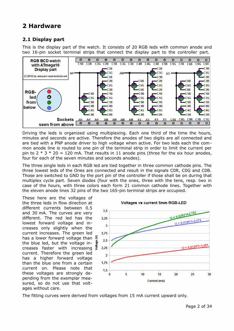
2.2 Controller part
This is the controller part with the ATmega16. It's I/O port A controls five color cathodes,port C further eight and port D the last eight. Current control through the leds is donewith resistors, which result from the different forward voltages of the three colors (see be-low). Note that the cathode port pins are active low, so a zero has to be written to theoutput when the cathode shall be on.
The currents through all leds, that are on over a multiplex period all sum up in the GNDpin of the controller. In order to limit those currents to the 200 mA (PDIP package), thatare specified as maximum load in the device's databook, the current through the leds wasselected to be 20 mA. The highest current is achieved when 57 is displayed: five leds areon. If two colors are selected (such as blue and red) ten led currents add up to 200 mA. Ifall three colors would be active (led color white) the maximum load on the GND pin wouldeither be exceeded or the individual led current would have to be limited to 13.3 mA. Thiswould also be possible, the difference is rarely seen by the human eye, but larger resistorvalues would result.
The three anodes are driven by the I/O port pins PB0 (Hours), PB1 (Minutes) and PB2(Seconds), via the PNP transistors BD440. Their base current is limited by the 1k resistors.The anode port pins are also active low (logical zero = on).
The two keys for adjusting the time are connected to the port pins PB3 and PB4. Bothhave their internal pull-up resistors on, so the keys are also active low.
The potentiometer of 100k divides the operating voltage and is connected with the ADconverter input pin ADC0.
The two XTAL pins are connected with a 4 MHz crystal and two 18 pF ceramic capactors.This crystal has to be invoked as source by setting the respective fuses (see below). Youcan use other crystals, too, but the constant clock and the whole clocking scheme in thesource code has to be changed then.
The port pins PB5, PB6 and PB7 serve exclusively the ISP6 interface over which the con-troller can be programmed within the running system.
Page 3 of 34

This accounts forthe number ofleds that areswitched on overeach second of aday. As the threedisplayed num-bers are multi-plexed, the 26does not reflecta complete cy-cle.
The resistorslimit the currentto 20 mA per ledcolor. The high-est currentsthrough all the leds occur on the end of the day, between 23:00 and 24:00 hours. The pic-ture demonstrates the large differences of current loads over this period.
At maximum, a current peak of 173 mA occurs over one second. This is well below thecurrent limit of the GND pin in the PDIP package.
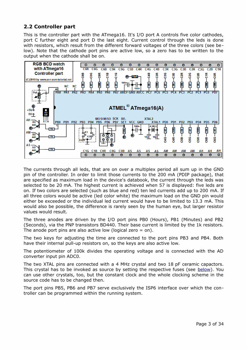
For the load of the power supply, besides the maximum current load, the minute averageplays a role for the stability of the supply. This is because the thermal load of the trans-former and the voltage regulator are two design characteristics. The diagram shows theminute averages over a whole day.
Page 4 of 34
By average theminute loadsare well below100 mA, only atthe end of anhour short peri-ods with highercurrents occur.These short pe-riods are notrelevant in thatcase, the 3.8VAtransformer andthe regulatorare well belowtheir designlimits.
2.3 Power supply
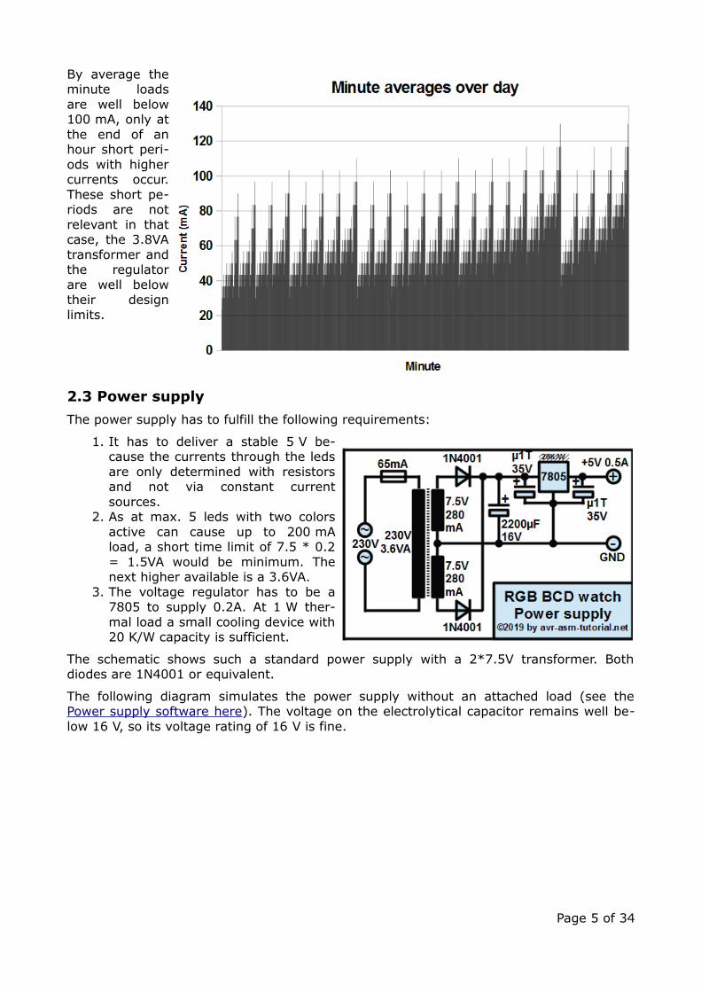
The power supply has to fulfill the following requirements:
1. It has to deliver a stable 5 V be-cause the currents through the ledsare only determined with resistorsand not via constant currentsources.
2. As at max. 5 leds with two colorsactive can cause up to 200 mAload, a short time limit of 7.5 * 0.2= 1.5VA would be minimum. Thenext higher available is a 3.6VA.
3. The voltage regulator has to be a7805 to supply 0.2A. At 1 W ther-mal load a small cooling device with20 K/W capacity is sufficient.
The schematic shows such a standard power supply with a 2*7.5V transformer. Bothdiodes are 1N4001 or equivalent.
The following diagram simulates the power supply without an attached load (see thePower supply software here). The voltage on the electrolytical capacitor remains well be-low 16 V, so its voltage rating of 16 V is fine.
Page 5 of 34
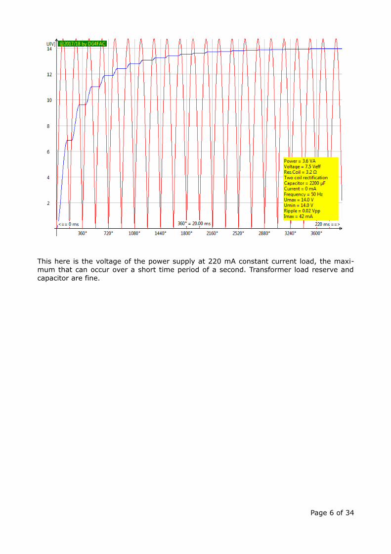
This here is the voltage of the power supply at 220 mA constant current load, the maxi-mum that can occur over a short time period of a second. Transformer load reserve andcapacitor are fine.
Page 6 of 34
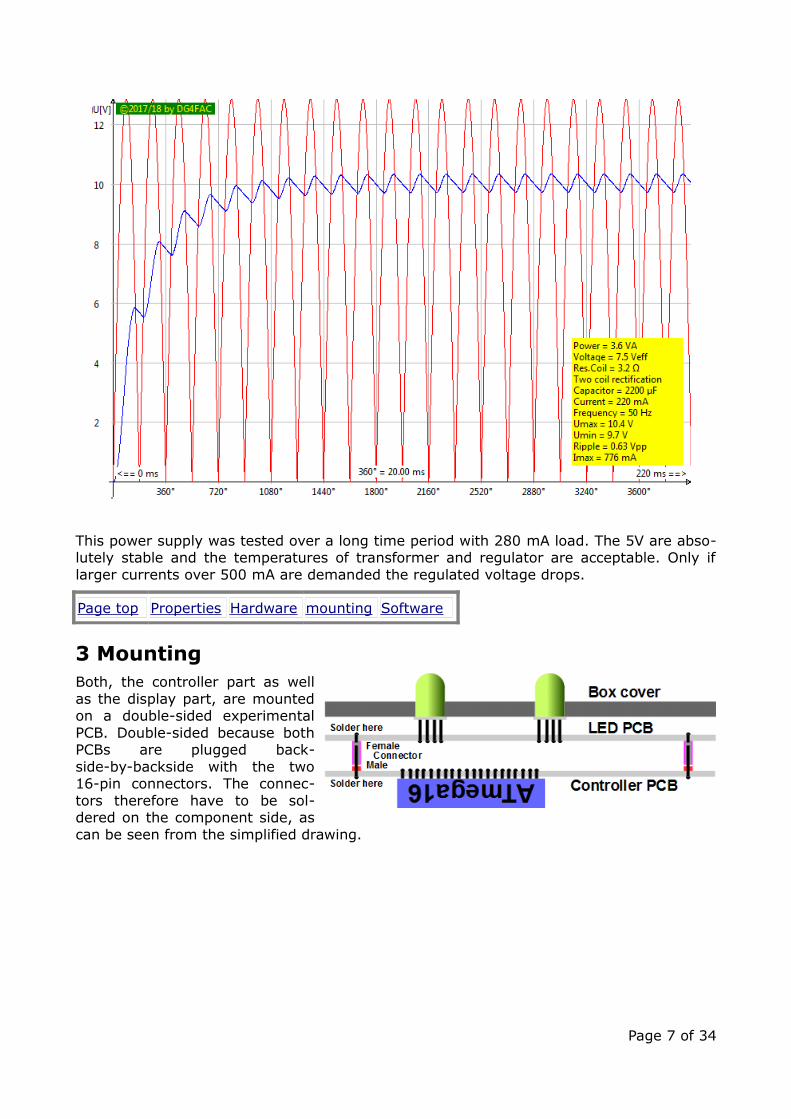
This power supply was tested over a long time period with 280 mA load. The 5V are abso-lutely stable and the temperatures of transformer and regulator are acceptable. Only iflarger currents over 500 mA are demanded the regulated voltage drops.
Page top Properties Hardware mounting Software
3 MountingBoth, the controller part as wellas the display part, are mountedon a double-sided experimentalPCB. Double-sided because bothPCBs are plugged back-side-by-backside with the two16-pin connectors. The connec-tors therefore have to be sol-dered on the component side, ascan be seen from the simplified drawing.
Page 7 of 34
3.1 LED PCB
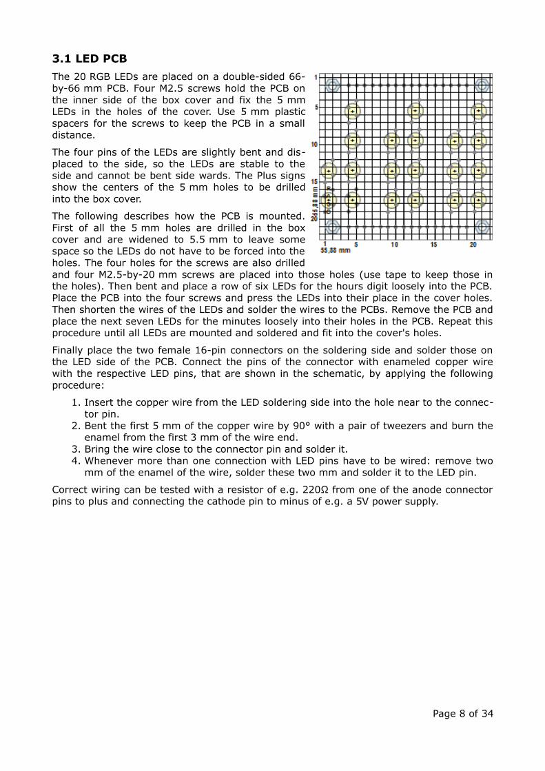
The 20 RGB LEDs are placed on a double-sided 66-by-66 mm PCB. Four M2.5 screws hold the PCB onthe inner side of the box cover and fix the 5 mmLEDs in the holes of the cover. Use 5 mm plasticspacers for the screws to keep the PCB in a smalldistance.
The four pins of the LEDs are slightly bent and dis-placed to the side, so the LEDs are stable to theside and cannot be bent side wards. The Plus signsshow the centers of the 5 mm holes to be drilledinto the box cover.
The following describes how the PCB is mounted.First of all the 5 mm holes are drilled in the boxcover and are widened to 5.5 mm to leave somespace so the LEDs do not have to be forced into theholes. The four holes for the screws are also drilledand four M2.5-by-20 mm screws are placed into those holes (use tape to keep those inthe holes). Then bent and place a row of six LEDs for the hours digit loosely into the PCB.Place the PCB into the four screws and press the LEDs into their place in the cover holes.Then shorten the wires of the LEDs and solder the wires to the PCBs. Remove the PCB andplace the next seven LEDs for the minutes loosely into their holes in the PCB. Repeat thisprocedure until all LEDs are mounted and soldered and fit into the cover's holes.
Finally place the two female 16-pin connectors on the soldering side and solder those onthe LED side of the PCB. Connect the pins of the connector with enameled copper wirewith the respective LED pins, that are shown in the schematic, by applying the followingprocedure:
1. Insert the copper wire from the LED soldering side into the hole near to the connec-tor pin.
2. Bent the first 5 mm of the copper wire by 90° with a pair of tweezers and burn theenamel from the first 3 mm of the wire end.
3. Bring the wire close to the connector pin and solder it. 4. Whenever more than one connection with LED pins have to be wired: remove two
mm of the enamel of the wire, solder these two mm and solder it to the LED pin.
Correct wiring can be tested with a resistor of e.g. 220Ω from one of the anode connectorpins to plus and connecting the cathode pin to minus of e.g. a 5V power supply.
Page 8 of 34

3.2 Controller PCB
This is the design of the controller's PCB with a size of 65-by-55 mm.
As the controller PCB is piggybacked on the LED PCB, pin rows and numbering changesaccordingly.
Both 16-pin male connectors are mounted from the soldering side of the PCB. Solderingprocedure for these is the same as for the female connectors on the display PCB.
When the power supply wires, the 40-pin IC socket for the ATmega16 (without the AT-mega16), the LED resistors, the anode driver transistors and the two connectors areplaced, soldered and wired, the LED PCB can be attached and the power can be appliedapplied. By connecting the anode driver pins 1, 2 or 3 on the socket with ground and byconnecting one of the cathode pins PA3 to PA7, PC0 to PC7 resp. PD0 to PD7 with GND theLEDs 0 to 5 (hours) resp. 0 to 6 (minutes, seconds) shall be on in the order blue - green –red.
If the power supply, the crystal with its two capacitors, the RESET resistor, the IC socketand the ISP6 connector are placed, soldered and wired, the ATmega16 can be plugged inand the ID bits of the controller can be read. The fuse bits of the ATmega16 can be pro-grammed to use the external crystal (see fuse programming). If both operations a5re suc-cesfull, you can bring the source code to accelerate the timing (by setting the constantcAccel in the source code to a higher value than 1, re-assemble and burn the hexcode tothe flash memory). This makes a day shorter so that, with cAccel = 8, it lasts only threehours, or, with cAccel = 64, only 22.5 minutes.
Page 9 of 34
Further hardware bug diagnostics are available in the source code and are described in thechapter Software.
3.3 Power supply PCB
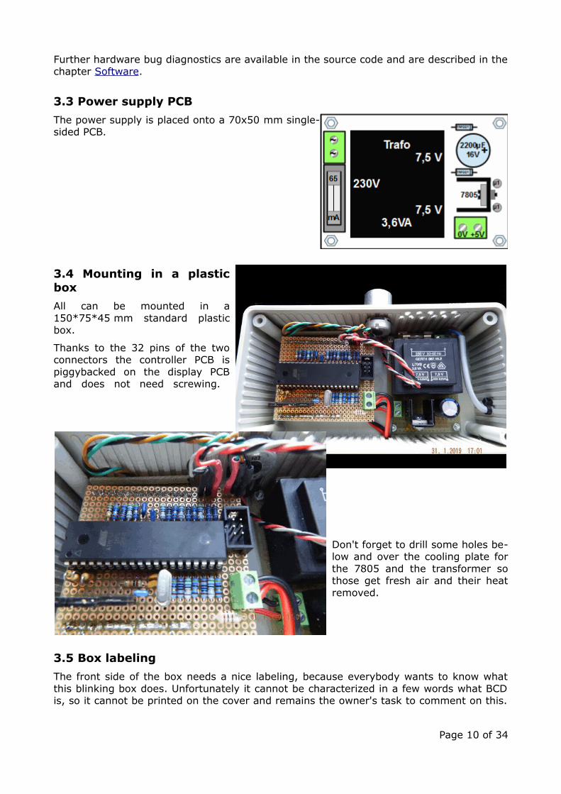
The power supply is placed onto a 70x50 mm single-sided PCB.
3.4 Mounting in a plasticbox
All can be mounted in a150*75*45 mm standard plasticbox.
Thanks to the 32 pins of the twoconnectors the controller PCB ispiggybacked on the display PCBand does not need screwing.
Don't forget to drill some holes be-low and over the cooling plate forthe 7805 and the transformer sothose get fresh air and their heatremoved.
3.5 Box labeling
The front side of the box needs a nice labeling, because everybody wants to know whatthis blinking box does. Unfortunately it cannot be characterized in a few words what BCDis, so it cannot be printed on the cover and remains the owner's task to comment on this.
Page 10 of 34
"Yes, it is a watch, but ..." and "You know, you add together the tens and the ones, bothencoded as powers of two ..." are some sentences that might be necessary.
Find some labeling (and all other drawings I made) as Open-Office-Draw file here.
Page top Properties Hardware mounting Software
4 Software
4.1 Downloads
The assembler source code for the watch can be downloaded from here and viewed in thebrowser here.
Additional documents for download:
• All schematics, drawings and graphical stuff in several draw sheets in this Open-Of-fice-Draw document here,
• all calculations for the watch (clock rates, RGB LED voltage analysis, measurementsand calculations of the Vce(sat) for the BD440, measured LED currents of the as-built prototype) are documented in the Open-Office spreadsheet here,
• the calculation of the current load in each second of a day and averaged over min-utes are in two sheets of the Open-Office spreadsheet here (Caution! The documentis very large, needs long time to load and to calculate!),
• all flow diagrams of the software are documented in the Open-Office draw docu-ment here.
If you use the watch as a gift, a nice handbook with at least 50 pages would be appropri-ate. Use anything you'll find on that web page to impress the new owner.
4.2 Assembling the source code
Prior to assembling make sure that no debugging switches are set in the source code (seebelow for those).
For assembling you need an assembler that is familiar with .IF directives. ATMEL's assem-bler 2 is fine for that. If you do not want to download more than 900 MB just to have anassembler, or if you don't have a Windows operating system, is better off with my ownone, gavrasm. How to assemble, if you have a 64-bit Windows is described here, for a 64-bit Linux here. Those who have a different operating system (32 bit, Mac-OS, etc.) shoulddownload the source code of gavrasm and compile their own with Free Pascal (FPC).
The assembled machine code shall be available in the same directory as .hex file.
Page 11 of 34
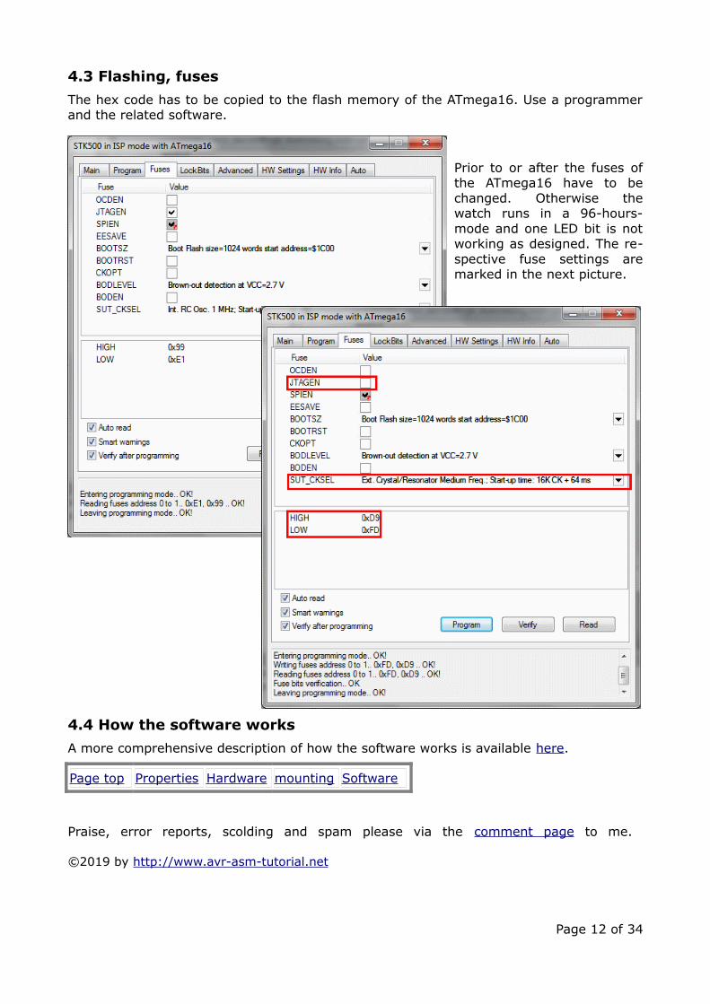
4.3 Flashing, fuses
The hex code has to be copied to the flash memory of the ATmega16. Use a programmerand the related software.
Prior to or after the fuses ofthe ATmega16 have to bechanged. Otherwise thewatch runs in a 96-hours-mode and one LED bit is notworking as designed. The re-spective fuse settings aremarked in the next picture.
4.4 How the software works
A more comprehensive description of how the software works is available here.
Page top Properties Hardware mounting Software
Praise, error reports, scolding and spam please via the comment page to me.
©2019 by http://www.avr-asm-tutorial.net
Page 12 of 34
Path: Home => AVR-EN => Applications => RGB BCD watch m16 => Software
AVR applications
RGB BCD watch with AT-mega16
Software for the BCDwatch
The software of the RGB BCD watch with AT-mega16This describes the software fot the BCD watch as provided as source code here and listedin the attachment.
Page top Diagnosis Time ADC Multiplexing Conversion AD complete
1 Hardware diagnosisThe software as provided has built-in functions that can assist hardware debugging. Thoseare switched on in the header lines of the assembler source code named Debuggingswitches. You can invoke those functions by defining those switches with setting the con-stants to Yes. Note that it does not make much sense to set more than one switch Yes asthose, in most cases, exclude each other. Following any changes, re-assemble and transferthe hex code to the flash memory of the controller.
1. "cAccel": This factor accelerates the watch by the given factor, so the functioning ofthe watch can be viewed in high speed. With N = 8 the eight-fold speed, with N =100 one hundred-fold speed can be tested, with N = 144 the whole day lasts 10minutes only.
2. "dbg_leds": With this function the LEDs are, one by one, switched on in the follow-ing row:
• Seconds - minutes - hours, • Ones - twos - fours - eights - tens - twenties - forties (seconds/minutes
only), • blue - green - red
for one second each. With that you can identify errors in wiring the LEDs. 3. "dbg_adc": The measured ADC value is displayed as hour (between 0 and 23). This
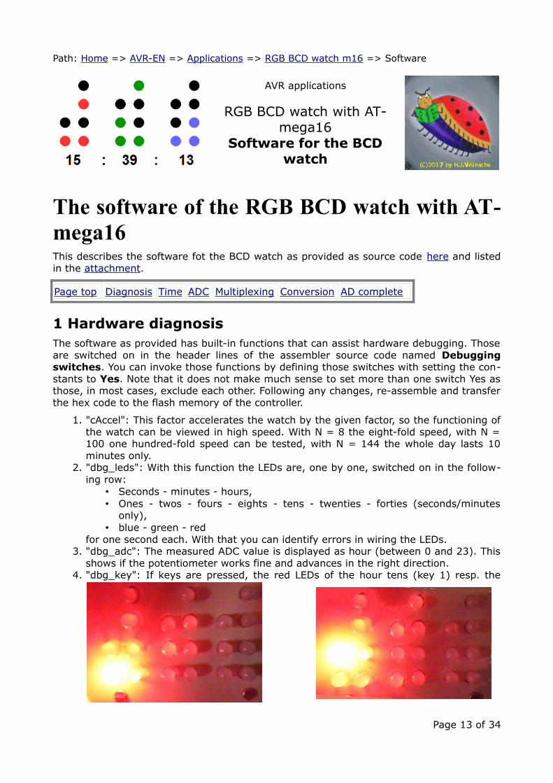
shows if the potentiometer works fine and advances in the right direction. 4. "dbg_key": If keys are pressed, the red LEDs of the hour tens (key 1) resp. the
Page 13 of 34
hour twenties (key 2) are on.If none of the keys are pressed, the LEDs remain dark.
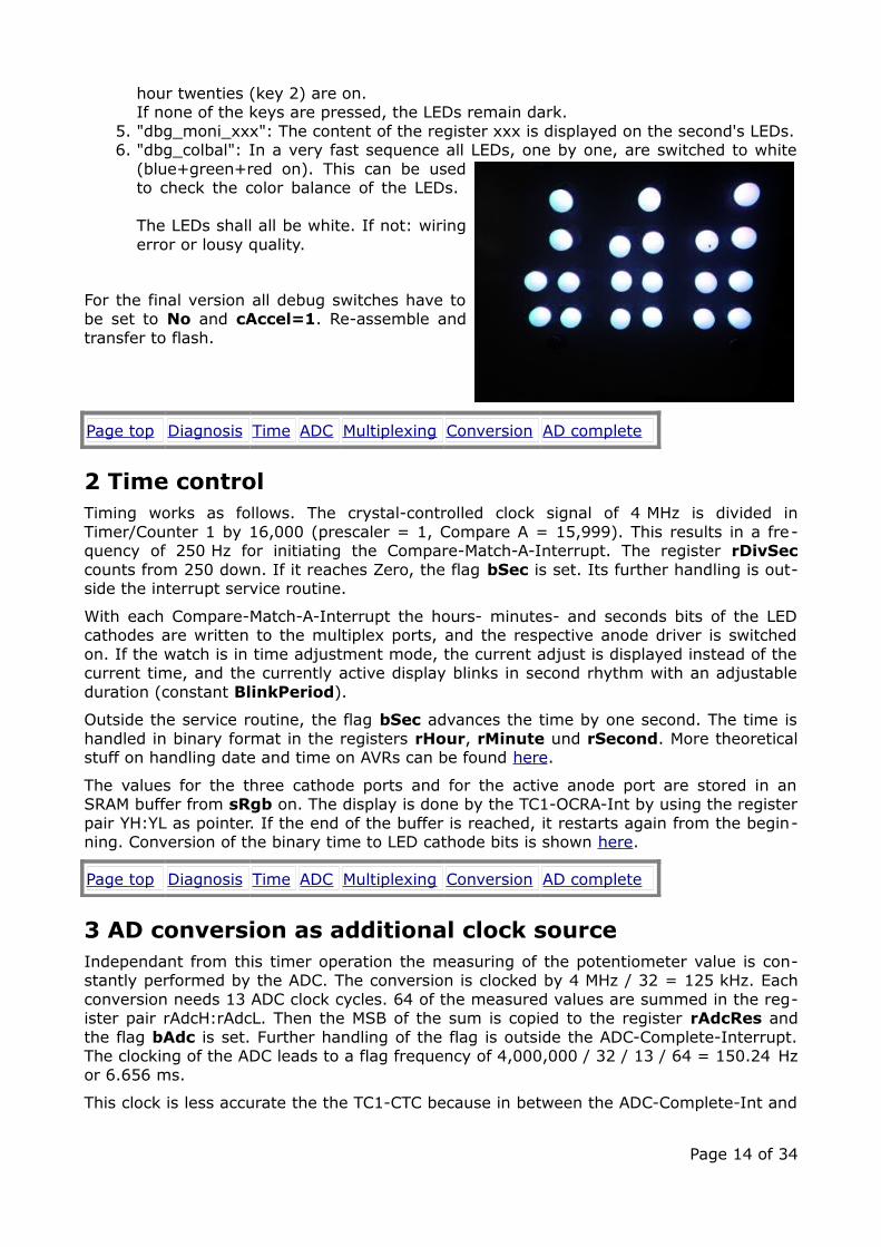
5. "dbg_moni_xxx": The content of the register xxx is displayed on the second's LEDs.6. "dbg_colbal": In a very fast sequence all LEDs, one by one, are switched to white
(blue+green+red on). This can be usedto check the color balance of the LEDs.
The LEDs shall all be white. If not: wiringerror or lousy quality.
For the final version all debug switches have tobe set to No and cAccel=1. Re-assemble andtransfer to flash.
Page top Diagnosis Time ADC Multiplexing Conversion AD complete
2 Time controlTiming works as follows. The crystal-controlled clock signal of 4 MHz is divided inTimer/Counter 1 by 16,000 (prescaler = 1, Compare A = 15,999). This results in a fre-quency of 250 Hz for initiating the Compare-Match-A-Interrupt. The register rDivSeccounts from 250 down. If it reaches Zero, the flag bSec is set. Its further handling is out-side the interrupt service routine.
With each Compare-Match-A-Interrupt the hours- minutes- and seconds bits of the LEDcathodes are written to the multiplex ports, and the respective anode driver is switchedon. If the watch is in time adjustment mode, the current adjust is displayed instead of thecurrent time, and the currently active display blinks in second rhythm with an adjustableduration (constant BlinkPeriod).
Outside the service routine, the flag bSec advances the time by one second. The time ishandled in binary format in the registers rHour, rMinute und rSecond. More theoreticalstuff on handling date and time on AVRs can be found here.
The values for the three cathode ports and for the active anode port are stored in anSRAM buffer from sRgb on. The display is done by the TC1-OCRA-Int by using the registerpair YH:YL as pointer. If the end of the buffer is reached, it restarts again from the begin-ning. Conversion of the binary time to LED cathode bits is shown here.
Page top Diagnosis Time ADC Multiplexing Conversion AD complete
3 AD conversion as additional clock sourceIndependant from this timer operation the measuring of the potentiometer value is con-stantly performed by the ADC. The conversion is clocked by 4 MHz / 32 = 125 kHz. Eachconversion needs 13 ADC clock cycles. 64 of the measured values are summed in the reg-ister pair rAdcH:rAdcL. Then the MSB of the sum is copied to the register rAdcRes andthe flag bAdc is set. Further handling of the flag is outside the ADC-Complete-Interrupt.The clocking of the ADC leads to a flag frequency of 4,000,000 / 32 / 13 / 64 = 150.24 Hzor 6.656 ms.
This clock is less accurate the the TC1-CTC because in between the ADC-Complete-Int and
Page 14 of 34
the restart of the AD converter some delay is introduced by instructions.
The flag bAdc adjusts the display brightness or, in case that time adjustment is active, thedisplay of the adjusted digit. More on this is in the chapter on key adjustment here.
Page top Diagnosis Time ADC Multiplexing Conversion AD complete
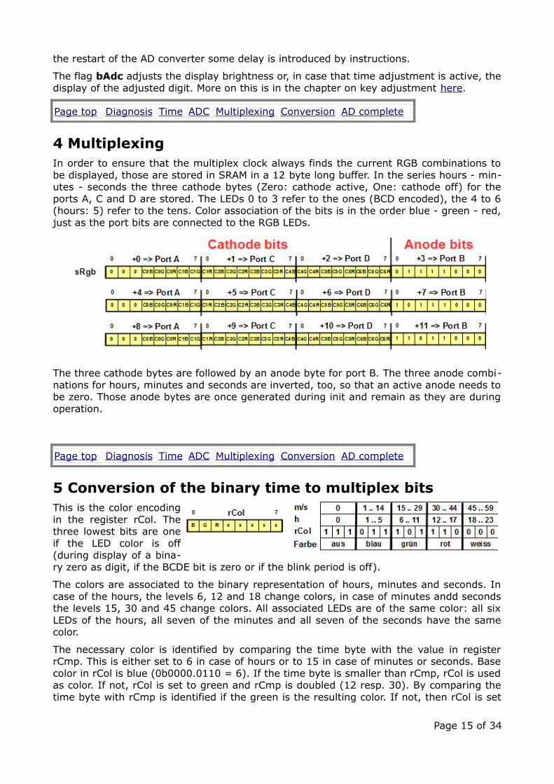
4 MultiplexingIn order to ensure that the multiplex clock always finds the current RGB combinations tobe displayed, those are stored in SRAM in a 12 byte long buffer. In the series hours - min-utes - seconds the three cathode bytes (Zero: cathode active, One: cathode off) for theports A, C and D are stored. The LEDs 0 to 3 refer to the ones (BCD encoded), the 4 to 6(hours: 5) refer to the tens. Color association of the bits is in the order blue - green - red,just as the port bits are connected to the RGB LEDs.
The three cathode bytes are followed by an anode byte for port B. The three anode combi-nations for hours, minutes and seconds are inverted, too, so that an active anode needs tobe zero. Those anode bytes are once generated during init and remain as they are duringoperation.
Page top Diagnosis Time ADC Multiplexing Conversion AD complete
5 Conversion of the binary time to multiplex bitsThis is the color encodingin the register rCol. Thethree lowest bits are oneif the LED color is off(during display of a bina-ry zero as digit, if the BCDE bit is zero or if the blink period is off).
The colors are associated to the binary representation of hours, minutes and seconds. Incase of the hours, the levels 6, 12 and 18 change colors, in case of minutes andd secondsthe levels 15, 30 and 45 change colors. All associated LEDs are of the same color: all sixLEDs of the hours, all seven of the minutes and all seven of the seconds have the samecolor.
The necessary color is identified by comparing the time byte with the value in registerrCmp. This is either set to 6 in case of hours or to 15 in case of minutes or seconds. Basecolor in rCol is blue (0b0000.0110 = 6). If the time byte is smaller than rCmp, rCol is usedas color. If not, rCol is set to green and rCmp is doubled (12 resp. 30). By comparing thetime byte with rCmp is identified if the green is the resulting color. If not, then rCol is set
Page 15 of 34

to the third color (red) and half of the doubled rCmp is added to rCmp (18 resp. 45).Again: if smaller this color is used, if not the fourth color is written to rCol (violet = redand blue).
After that rCmp is in any case set to 15 for further minute and second comparisons.
This shows the algorithm that is used to convert the time binaries inregister rmp (either hours, minutes or seconds) to BCD encoded valuesin rBcd: continued subtraction of ten from the binary and adding therest of the binary with OR. The following tricks are used:
1. The result is set to minus 0x10, so that the first addition of tenleads to zero (in case the binary is smaller than ten.
2. Addition of ten to rBcd by using SUBI rBcd,-0x10 as replacementfor the missing ADDI instruction in AVR assembler.
3. Then subtraction of ten from the binary in rmp. If following thatinstruction the carry bit is clear, then further adding 10 to rBcdand subtracting 10 from rmp is performed. If carry is set, theloop is terminated.
4. By adding 10 to rmp (SUBI rmp,-10) the last subtraction is can-celled.
5. By OR-ing the upper nibble in rBcd and the lower nibble in rmp,the result is generated and the conversion ends.
That demonstrates how the conversion of the color bits into multiplex bits works. A copyof the color bits in rCol is three times shifted right, bit by bit, to the carry flag and then ro-tated left into the three (previously cleared) bytes R0:R1:R2.
After having so shifted seven color triples into the registers R0:R1:R2 the three byteshave the correct color bits for the cathodes and can be copied to SRAM.
This is the complete algorithm of the conversion in Assembler. To be able to convert thetime as well as the input time (under time adjustment mode) with the same routine, theaddress in Z either points to the time (in the three registers) or to the input time (inSRAM).
1. Init starts with setting the pointers Z (to the time) and X (to the multiplex buffer)and setting rCmp to 6 (hours).
2. The first step of the loop is reading a time byte from Z. 3. By comparing it with the value in rCmp, 2*rCmp and 3*rCmp/4 the color value is
determined and rCol is either set to cColor1, cColor2, cColor3 or cColor4. 4. The time byte is re-read from Z and converted to BCD in register rBcd.
Page 16 of 34
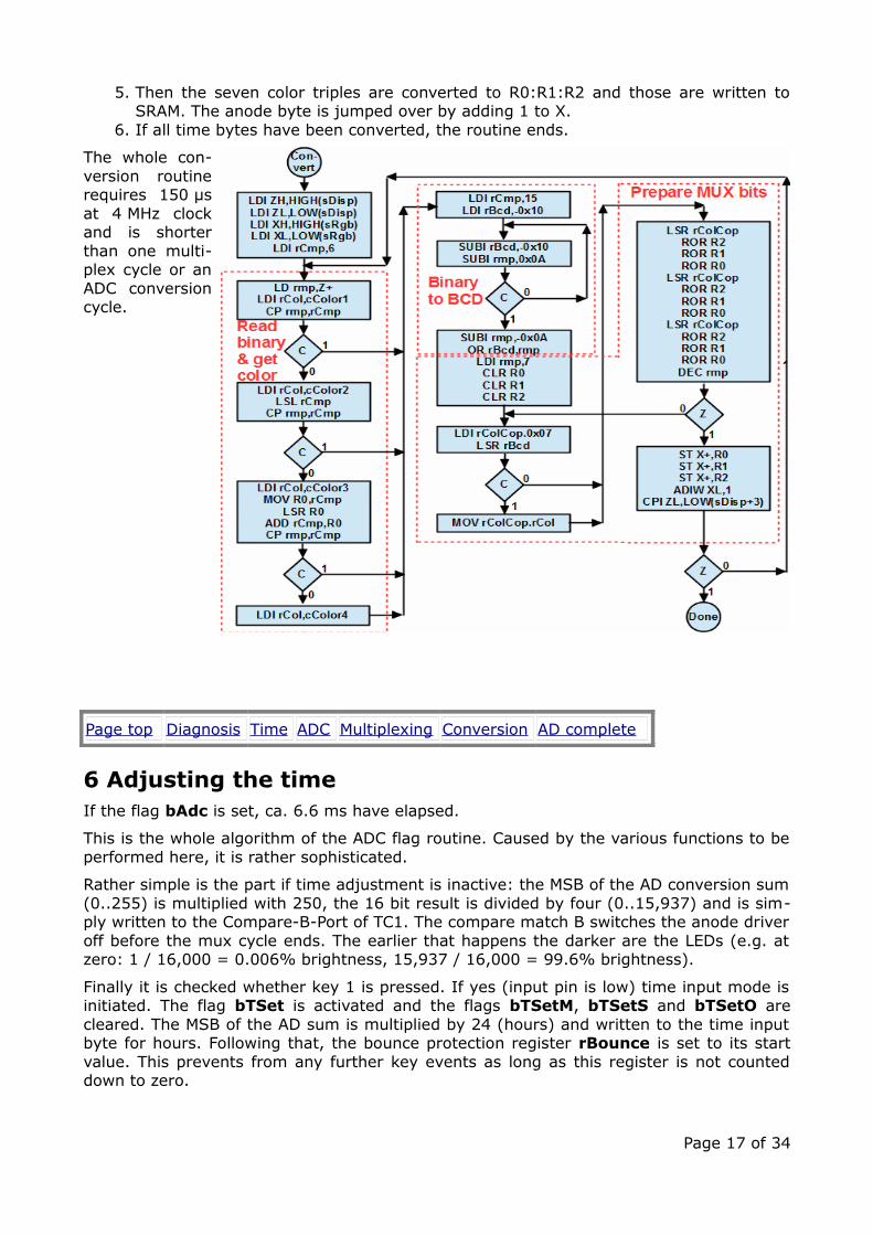
5. Then the seven color triples are converted to R0:R1:R2 and those are written toSRAM. The anode byte is jumped over by adding 1 to X.
6. If all time bytes have been converted, the routine ends.
The whole con-version routinerequires 150 µsat 4 MHz clockand is shorterthan one multi-plex cycle or anADC conversioncycle.
Page top Diagnosis Time ADC Multiplexing Conversion AD complete
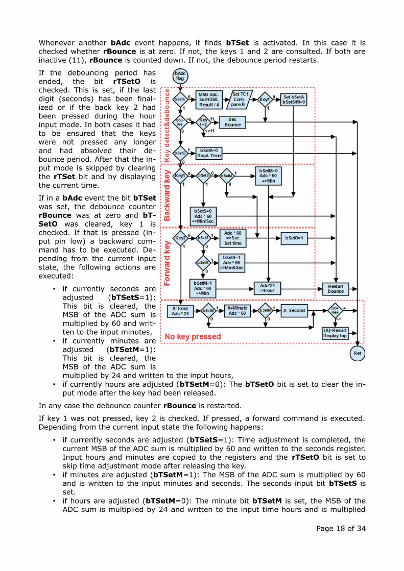
6 Adjusting the timeIf the flag bAdc is set, ca. 6.6 ms have elapsed.
This is the whole algorithm of the ADC flag routine. Caused by the various functions to beperformed here, it is rather sophisticated.
Rather simple is the part if time adjustment is inactive: the MSB of the AD conversion sum(0..255) is multiplied with 250, the 16 bit result is divided by four (0..15,937) and is sim-ply written to the Compare-B-Port of TC1. The compare match B switches the anode driveroff before the mux cycle ends. The earlier that happens the darker are the LEDs (e.g. atzero: 1 / 16,000 = 0.006% brightness, 15,937 / 16,000 = 99.6% brightness).
Finally it is checked whether key 1 is pressed. If yes (input pin is low) time input mode isinitiated. The flag bTSet is activated and the flags bTSetM, bTSetS and bTSetO arecleared. The MSB of the AD sum is multiplied by 24 (hours) and written to the time inputbyte for hours. Following that, the bounce protection register rBounce is set to its startvalue. This prevents from any further key events as long as this register is not counteddown to zero.
Page 17 of 34
Whenever another bAdc event happens, it finds bTSet is activated. In this case it ischecked whether rBounce is at zero. If not, the keys 1 and 2 are consulted. If both areinactive (11), rBounce is counted down. If not, the debounce period restarts.
If the debouncing period hasended, the bit rTSetO ischecked. This is set, if the lastdigit (seconds) has been final-ized or if the back key 2 hadbeen pressed during the hourinput mode. In both cases it hadto be ensured that the keyswere not pressed any longerand had absolved their de-bounce period. After that the in-put mode is skipped by clearingthe rTSet bit and by displayingthe current time.
If in a bAdc event the bit bTSetwas set, the debounce counterrBounce was at zero and bT-SetO was cleared, key 1 ischecked. If that is pressed (in-put pin low) a backward com-mand has to be executed. De-pending from the current inputstate, the following actions areexecuted:
• if currently seconds areadjusted (bTSetS=1):This bit is cleared, theMSB of the ADC sum ismultiplied by 60 and writ-ten to the input minutes,
• if currently minutes areadjusted (bTSetM=1):This bit is cleared, theMSB of the ADC sum ismultiplied by 24 and written to the input hours,
• if currently hours are adjusted (bTSetM=0): The bTSetO bit is set to clear the in-put mode after the key had been released.
In any case the debounce counter rBounce is restarted.
If key 1 was not pressed, key 2 is checked. If pressed, a forward command is executed.Depending from the current input state the following happens:
• if currently seconds are adjusted (bTSetS=1): Time adjustment is completed, thecurrent MSB of the ADC sum is multiplied by 60 and written to the seconds register.Input hours and minutes are copied to the registers and the rTSetO bit is set toskip time adjustment mode after releasing the key.
• if minutes are adjusted (bTSetM=1): The MSB of the ADC sum is multiplied by 60and is written to the input minutes and seconds. The seconds input bit bTSetS isset.
• if hours are adjusted (bTSetM=0): The minute bit bTSetM is set, the MSB of theADC sum is multiplied by 24 and written to the input time hours and is multiplied
Page 18 of 34

by 60 and written to the input time minutes.
In all cases the rBounce counter is restarted.
If neither key 1 nor key 2 are pressed, the current input position (hours, minutes, sec-onds) is pointed to in X and, depending from that, the MSB of the ADC sum is either mul-tiplied by 24 or 60. If the current and the previous value differ, it is re-written, the cath-ode bits are caclulated and written to the display mux.
Not shown here is the algorithm for the time-out of the time adjustment. This uses theregister pair rInpToH:rInpToL. This is decremented each time that no action occurredand is restarted by each key event. If it reaches zero, the input mode is switched off with-out setting the time. The time-out can be at maximum set to seven minutes (constant In-putTimeOutMinutes).
Page top Diagnosis Time ADC Multiplexing Conversion AD complete
Praise, error reports, scolding and spam please via the comment page to me.
©2019 by http://www.avr-asm-tutorial.net
Page 19 of 34

Path: Home => AVR-EN => Applications => RGB BCD watch m16 => Assembler source code
AVR applications
RGB BCD watch with AT-mega16
Software for the RGB BCDwatch
Assembler source code for the RGB BCDwatchThe original source code in assembler format is available here.
;; ***********************************; * RGB BCD watch with ATmega16 *; * Version 1.0 as of January 2019 *; * (C)2019 by avr-asm-tutorial.net *; ***********************************;.nolist.include "m16adef.inc" ; Define device ATmega16A.list;; *************************************; D E B U G G I N G S W I T C H E S; *************************************;; Accelerate watch by a factor.equ cAccel = 1 ; Acceleration of clock, 1..1000; (should be 1 in final version);.equ Yes = 1 ; Yes for all switches.equ No = 0 ; No for all switches;; Light all LEDs in all colors one by one in the rows:; 1. blue - green - red for delay seconds each; 2. ones, twos, fours, eights, tens, twenties, fourties; 3. seconds - minutes - hours.equ dbg_leds = No ; Should be no in final version.equ dbg_leds_delay = 10 ; On-Time in 50 ms multiples;; Debug the ADC: Set hours to MSB result.equ dbg_adc = No ; Should be no in final version;; Debug the keys:; Leds dark if no key pressed; Set hour tens red on key 1; Set hour twenties on key 2; (Disables all normal operation!).equ dbg_key = No;; Debug the color balance:; Lights all three LEDs around and around
Page 20 of 34
; (Disables all normal operation!).equ dbg_colbal = No;; Monitoring of registers during input phase.equ dbg_moni_flags = No ; Monitor the flags.equ dbg_moni_bounce = No ; Monitor the bounce counter;;; **********************************; H A R D W A R E; **********************************;; Device: ATmega16A, Package: 40-pin-PDIP; __________; 1 / |40; AH o--|PB0 PA0|--o POT; AM o--|PB1 PA1|--o NC; AS o--|PB2 PA2|--o NC; K1 o--|PB3 PA3|--o C0B; K2 o--|PB4 PA4|--o C0G; MOSI o--|PB5 PA5|--o C0R; MISO o--|PB6 PA6|--o C1B; SCK o--|PB7 PA7|--o C1G; RES o--|RESET AREF|--o AREF; +5V o--|VCC GND|--o 0V; 0V o--|GND AVCC|--o AVCC; 4MHz o--|XTAL2 PC7|--o C4B; XTAL o--|XTAL1 PC6|--o C3R; C4G o--|PD0 PC5|--o C3G; C4R o--|PD1 PC4|--o C3B; C5B o--|PD2 PC3|--o C2R; C5G o--|PD3 PC2|--o C2G; C5R o--|PD4 PC1|--o C2B; C6B o--|PD5 PC0|--o C1R; C6G o--|PD6 PD7|--o C6R; 20|___________|21;;; **********************************; P O R T S A N D P I N S; **********************************;.equ pRgbC1O = PORTA ; RGB1 Cathode Output port.equ pRgbC1D = DDRA ; RGB1 Cathode Direction port.equ bRgbC1M = 0xF8 ; RGB1 Cathode Output Mask.equ pRgbC2O = PORTC ; RGB2 Cathode Output port.equ pRgbC2D = DDRC ; RGB2 Cathode Direction port.equ pRgbC2M = 0xFF ; RGB2 Cathode Output Mask.equ pRgbC3O = PORTD ; RGB3 Cathode Output port.equ pRgbC3D = DDRD ; RGB3 Cathode Direction port.equ pRgbC3M = 0xFF ; RGB3 Cathode Output Mask.equ pRgbAO = PORTB ; RGB Anode Output port.equ pRgbAD = DDRB ; RGB Anode Direction port.equ pRgbAM = 0x07 ; RGB Anode Mask.equ pKeyI = PINB ; Key input port.equ bKey1 = PINB3 ; First key.equ bKey2 = PINB4 ; Second key;; ******************************************; A D J U S T A B L E C O N S T A N T S; ******************************************
Page 21 of 34

;.equ clock=4000000 ; Define clock frequency;; Constants for color composition.equ bBlue = 0 ; Blue led bit.equ bGreen = 1 ; Green led bit.equ bRed = 2 ; Red led bit;; Colors for the four quarters.equ cColor1 = 255-(1<<bBlue) ; Color quarter 1.equ cColor2 = 255-(1<<bGreen) ; Color quarter 2.equ cColor3 = 255-(1<<bRed) ; Color quarter 3.equ cColor4 = 255-((1<<bRed)|(1<<bBlue)) ; Color quarter 4; Error checking of colors.if ((cColor1&0x07)==0)||((cColor2&0x07)==0)||((cColor3&0x07)==0)||((cColor4&0x07)==0) .error "One of the colors has three color bits at zero!" .endif;; Start time of watch: time to be set at start-up.equ starthour = 20 ; Start at 20 hours.equ startminute = 0 ; Start at zero minute.equ startsecond = 0 ; Start at zero seconds;; When key input active: blink hour/minute/second.equ BlinkPeriod = 85 ; 85% on, 15% off;; Key input bouncing parameter.equ BouncePeriod = 50 ; Debouncing period for keys in ms;; Input active time-out.equ InputTimeOutMinutes = 5 ; Time in minutes to skip input period.if InputTimeOutMinutes > 7 .error "Input time-out minutes too large!" .endif;; ****************************************************; F I X E D & D E R I V I V E D C O N S T A N T S; ****************************************************;; Clock signals for second increase and MUX; Clock > Presc > CTC > SecDiv > Seconds; 4 MHz 1 16000 250.equ cTc1Presc = 1 ; TC1 Prescaler.equ cTc1Clk = clock / cTc1Presc ; Frequency TC1.equ cTc1CompA = 15999 ; Int for Mux.equ cSecDiv = cTc1Clk/(cTc1CompA+1) ; TC0 Second divider;; Switch leds off after blink period.equ cBlinkOff = ((100-BlinkPeriod)*cSecDiv+50) / 100 ; Second divider;; ADC constants.equ cAdcCnt = 64 ; Sum up 64 ADC results.equ cAdcPs = 32 ; ADC prescaler.equ cAdcN = 13 ; Number of cycles.equ cAdcTime = (cAdcCnt*cAdcPs*cAdcN*1000)/clock ; Time in ms.equ cInpTO = 65536-(clock/cAdcCnt/cAdcPs/cAdcN)*60*InputTimeOutMinutes.if cInpTO < 0 .error "Input time-out too long!" .endif.equ cBounce = (BouncePeriod+cAdcTime/2)/cAdcTime+1 ; Bounce counter
Page 22 of 34
;; **********************************; R E G I S T E R S; **********************************;; used: R2:R1:R0 for binary conversion to color.def rInpToL = R3 ; Time out input, LSB.def rInpToH = R4 ; dto., MSB.def rHrInp = R5 ; Input hour .equ sInput = 5.def rMinInp = R6 ; Input minute.def rSecInp = R7 ; Input second.def rCmp = R8 ; Compare value for conversion.def rConvCnt = R9 ; Counter for time conversion.def rAdcRes = R10 ; MSB of ADC sum.def rAdcL = R11 ; ADC sum, LSB.def rAdcH = R12 ; dto., MSB.def rAdcCnt = R13 ; ADC counter.def rSecDiv = R14 ; Seconds divider.def rSreg = R15 ; Save/Restore status port.def rmp = R16 ; Define multipurpose register.def rimp = R17 ; Multipurpose inside ints; Flags for flow control.def rFlag = R18 ; Flag register ; Those four bits control key input ; OSM_ = xxx0 = Normal operation, no time setting, no monitoring ; = 0001 = Time setting hours, monitoring = Led one green ; = 0011 = dto., minutes, monitoring = Led two blue ; = 0111 = dto., seconds, monitoring = Led four green ; = 1xx1 = dto., end time setting, monitoring = Leds eight/ten/twenty .equ bSetA = 0 ; Key flag, for hour setting .equ bSetM = 1 ; Flag for minute setting .equ bSetS = 2 ; Flag for second setting .equ bSetO = 3 ; Flag for end of time setting ; bBlink set when bSetA=1 and rSecDiv cycle reaches switching value .equ bBlink = 4 ; Switch active leds off ; bNoUpd set when bBlink is set, cleared at second start .equ bNoUpd = 5 ; Do not update during off-period ; Set by TC1A-ISR when a second is over .equ bSec = 6 ; Flag second over ; Set by ADC-Complete ISR when 64 measurements completed .equ bAdc = 7 ; ADC flag.def rHr = R19 ; Time hours .equ sTime = 19 ; Pointer to time info for displaying time.def rMin = R20 ; Time minutes.def rSec = R21 ; Time seconds.def rCol = R22 ; Color.def rColCop = R23 ; Copy of rCol.def rBcd = R24 ; BCD coded time.def rBounce = R25 ; Debouncing counter for key inputs; used: R27:R26 = X for conversion to cathode bits outside ints; used: R29:R28 = Y for pointer for multiplexing cycle; used: R31:R30 = Z for diverse purposes outside ints;; **********************************; S R A M; **********************************;.dseg.org SRAM_START;
Page 23 of 34
; MUX buffersRgb:.byte 4 ; Four bytes: RGBC1, RGBC2, RGBC3,AGBA, Hours.byte 4 ; Four bytes: RGBC1, RGBC2, RGBC3,AGBA, Minutes.byte 4 ; Four bytes: RGBC1, RGBC2, RGBC3,AGBA, SecondssRgbEnd:;; **********************************; C O D E; **********************************;.cseg.org 000000;; *************************************; R E S E T & I N T - V E C T O R S; ************************************* rjmp Main ; Reset vector nop reti ; INT0, unused nop reti ; INT1, unused nop reti ; OC2, unused nop reti ; OVF2, unused nop reti ; ICP1, unused nop rjmp Oc1AIsr ; OC1A, MUX and second counting nop rjmp Oc1BIsr ; OC1B, anode driver off for dimming nop reti ; OVF1, unused nop reti ; OVF0, unused nop reti ; SPI, unused nop reti ; URXC, unused nop reti ; UDRE, unused nop reti ; UTXC, unused nop rjmp AdccIsr ; ADCC, ADC cycle nop reti ; ERDY, unused nop reti ; ACI, unused nop reti ; TWI, unused nop reti ; INT2, unused nop reti ; OC0, unused nop reti ; SPMR, unused nop;; *****************************************
Page 24 of 34
; I N T - S E R V I C E R O U T I N E S; *****************************************;; TC1 Compare Match A Interrupt Service RoutineOc1AIsr: in rSreg,SREG ; Save SREG dec rSecDiv ; Decrease second divider brne Oc1AIsr1 ; Not zero, perform MUX ldi rimp,cSecDiv ; Restart seconds divider mov rSecDiv,rimp sbr rFlag,1<<bSec ; Set seconds flag cbr rFlag,1<<bNoUpd ; Updates onOc1AIsr1: ldi rimp,0x1F ; Clear anode drivers out pRgbAO,rimp ld rimp,Y+ ; Read first cathodes out pRgbC1O,rimp ; Write first RGB port ld rimp,Y+ ; Read second cathodes out pRgbC2O,rimp ; Write second RGB port ld rimp,Y+ ; Read third cathodes out pRgbC3O,rimp ; Write third RGB port ld rimp,Y+ ; Read anodes out pRgbAO,rimp ; Write anode cpi YL,sRgbEnd ; End of buffer? brne Oc1AIsr2 ; No ldi YH,High(sRgb) ; Restart Mux ldi YL,Low(sRgb)Oc1AIsr2: sbrs rFlag,bSetA ; Key input active? rjmp Oc1AIsr3 ; No ldi rimp,cBlinkOff ; Seconds divider reached off? cp rimp,rSecDiv ; Blink cycle reached brne Oc1AIsr3 ; No, skip flag setting sbr rFlag,(1<<bBlink)|(1<<bNoUpd) ; Set blink flag to turn input offOc1AIsr3: out SREG,rSreg ; Restore SREG reti;; OC1B Interrupt Service Routine; switches anode driver off for dimmingOc1BIsr: ldi rimp,0b00011111 ; Anode driver bits to one out pRgbAO,rimp ; in anode driver port reti;; ADC Conversion Complete Interrupt Service Routine; sums up 64 results, if complete: copy MSB, clear sum, set flag; restart ADC conversionAdccIsr: in rSreg,SREG ; Save SREG in rimp,ADCL ; Read ADC result LSB add rAdcL,rimp ; add to sum LSB in rimp,ADCH ; Read MSB adc rAdcH,rimp ; add to MSB dec rAdcCnt ; Decrease counter brne AdccIsr1 ; Not zero, restart ADC mov rAdcRes,rAdcH ; Copy MSB result clr rAdcL ; Restart sum LSB clr rAdcH ; dto., MSB ldi rimp,cAdcCnt ; Restart counter mov rAdcCnt,rimp ; in counter register
Page 25 of 34
sbr rFlag,1<<bAdc ; Set ADC flagAdccIsr1: ; Restart ADC ldi rimp,(1<<ADEN)|(1<<ADSC)|(1<<ADIE)|(1<<ADPS2)|(1<<ADPS0) out ADCSRA,rimp ; in ADC control port out SREG,rSreg ; Restore SREG reti;; **********************************; M A I N P R O G R A M I N I T; **********************************;Main: ldi rmp,High(RAMEND) ; End of SRAM, MSB out SPH,rmp ; Init MSB stack pointer ldi rmp,Low(RAMEND) ; End of SRAM, LSB out SPL,rmp ; Init LSB stack pointer ; Init SRAM MUX buffer ldi XH,High(sRgb) ; Point to SRAM buffer, MSB ldi XL,Low(sRgb) ; dto., LSBMain1: ldi rmp,0b11111000 ; First buffer byte st X+,rmp ; Cathodes 1 off ldi rmp,0xFF ; all others FF st X+,rmp ; Cathodes 2 off st X+,rmp ; Cathodes 3 off adiw XL,1 ; Jump over anode byte cpi XL,Low(sRgbEnd) ; End of buffer? brne Main1 ; No, go on ldi rmp,0b00011110 ; Anode driver hours sts sRgb+3,rmp ; Hour anode active ldi rmp,0b00011101 ; Anode driver miinutes sts sRgb+7,rmp ; Minute anode active ldi rmp,0b00011011 ; Anode driver seconds sts sRgb+11,rmp ; Second anode active ; Init the I/O ports ldi rmp,pRgbAM|(1<<bKey1)|(1<<bKey2) ; RGB Anode Mask plus key pull-ups out pRgbAO,rmp ; RGB Anode Output port ldi rmp,pRgbAM ; RGB Anode Mask out pRgbAD,rmp ; RGB Anode Direction port ldi rmp,bRgbC1M ; RGB1 Cathode Output Mask out pRgbC1O,rmp ; RGB1 Cathode Output port out pRgbC1D,rmp ; RGB1 Cathode Direction port ldi rmp,pRgbC2M ; RGB2 Cathode Output Mask out pRgbC2O,rmp ; RGB2 Cathode Output port out pRgbC2D,rmp ; RGB2 Cathode Direction port ldi rmp,pRgbC3M ; RGB3 Cathode Output Mask out pRgbC3O,rmp ; RGB3 Cathode Output port out pRgbC3D,rmp ; RGB3 Cathode Direction port;; *************************************; H A R D W A R E D E B U G G I N G; *************************************;; Routines for hardware debugging; Those do not perform normal counting but; end in indefinite loops!.if dbg_key == Yes ; Debug the attached keys ; Set hour tens red if key 1 pressed ; Set hour twenties red if key 2 pressed
Page 26 of 34

ldi rmp,0b00011110 ; Anode hours on out pRgbAO,rmp dbg_key_loop: sbic pKeyI,bKey1 ; Skip if key 1 low sbi pRgbC3O,PORTD1 ; Red LED off sbis pKeyI,bKey1 ; Skip if key 1 high cbi pRgbC3O,PORTD1 ; Red LED on sbic pKeyI,bKey2 ; Skip if key 2 low sbi pRgbC3O,PORTD4 ; Red LED off sbis pKeyI,bKey2 ; Skip if key 2 high cbi pRgbC3O,PORTD4 ; Red Led on rjmp dbg_key_loop ; Repeat on and on again .endif.if dbg_colbal == Yes ; Debug the color balance of all leds ; Switch all leds to white one by one ; and fastly change to the next led ; Colors should be clean white, but ; only 1/20th brightness ColBal_loop: ldi rMin,0xFF ; Start with upper leds off ldi rHr,0xFF ColBal_loop1: ldi rBcd,0b00011011 ; Start anodes with seconds ColBal_loop2: ldi rSec,0b11000000 ; Start with seconds ones ldi rmp,20 ; 20 leds to cycle ColBal_loop3: out pRgbC1O,rSec ; Set cathodes, seconds out pRgbC2O,rMin ; dto., minutes out pRgbC3O,rHr ; dto., hours out pRgbAO,rBcd ; Set anode driver ori rSec,0b00000111 ; Set all three lower bits lsl rSec ; Shift to next led, seconds rol rMin ; dto., minutes rol rHr ; dto., hours lsl rSec ; and to overnext led rol rMin rol rHr lsl rSec ; and to third led rol rMin rol rHr dec rmp brne ColBal_loop3 ; Continue led out and shift ori rBcd,0b00100000 ; Set next key to one lsr rBcd ; Next anode brcs ColBal_loop2 ; Not at the end rjmp ColBal_loop1 ; Restart all new .endif.if dbg_leds == Yes ; Debug the leds: Set the leds ; a) blue-green-red, ; b) ones, twos, fours, eights, tens, twentys, fourtys ; c) seconds, minutes, hours Led_loop1: ldi rMin,0xFF ; Upper leds off ldi rHr,0xFF ldi rBcd,0b00011011 ; Start anodes seconds Led_loop2: ldi rSec,0b11110000 ; Start with seconds ones ldi rmp,21 ; 21 leds to cycle
Page 27 of 34
sbrs rBcd,0 ; Hour cycle? ldi rmp,18 ; 18 leds only Led_loop3: out pRgbC1O,rSec ; Set cathodes, second out pRgbC2O,rMin ; dto., minute out pRgbC3O,rHr ; dto., hour out pRgbAO,rBcd ; Set anode driver ldi rCol,dbg_leds_delay ; Multiple 50 ms delay Led_loop4: ldi ZH,High((5*clock)/400) ; Delay loop 50 ms, MSB ldi ZL,Low((5*clock)/400) ; dto., LSB Led_loop5: sbiw ZL,1 ; Count down, 2 clock cycles brne Led_loop5 ; 2 clock cycles for branching ; 4 clock cycles = 1 us @4 MHz ; 50.000 us per loop dec rCol ; Count delay down brne Led_loop4 ; Next delay cycle ori rSec,0b00000100 ; Set blue cathode led 0 off lsl rSec ; Next cathode, second rol rMin ; Next cathode, minute rol rHr ; Next cathode, hour dec rmp ; Downcount led brne Led_loop3 ; Next led output lsr rBcd ; Next anode brcs Led_loop2 ; Restart with first led rjmp Led_loop1 ; Restart at the beginning .endif; *****************************************; C O N T I N U E N O R M A L I N I T; ***************************************** ; Init the start time of the watch ldi rHr,starthour ldi rMin,startminute ldi rSec,startsecond ; Init the ADC ldi rmp,1<<REFS0 ; VREF=AVCC, ADC channel 0 out ADMUX,rmp ; to MUX port clr rAdcL ; Restart sum LSB clr rAdcH ; dto., MSB ldi rmp,cAdcCnt ; Restart counter mov rAdcCnt,rmp ; Start the ADC: Int Enable, clock prescaler = 32 ldi rmp,(1<<ADEN)|(1<<ADSC)|(1<<ADIE)|(1<<ADPS2)|(1<<ADPS0) out ADCSRA,rmp ; in ADC control port ; Init TC1 as MUX/second timer/anode driver off ldi rmp,High(cTC1CompA/cAccel) ; CTC compare value, MSB out OCR1AH,rmp ; to compare port MSB ldi rmp,Low(cTC1CompA/cAccel) ; dto., LSB out OCR1AL,rmp ; dto., LSB clr rmp ; Switch LEDs to lowest brightness out OCR1BH,rmp ; MSB out OCR1BL,rmp ; LSB ldi rmp,0 ; WGM10 and WGM11 to 0 out TCCR1A,rmp ldi rmp,(1<<WGM12)|(1<<CS10) ; CTC on compare A, Prescaler=1 out TCCR1B,rmp ; Start TC1 ldi rmp,(1<<OCIE1A)|(1<<OCIE1B) ; Enable compare match interrupts out TIMSK,rmp ; in timer interrupt mask ; Init flags clr rFlag ; All flags off
Page 28 of 34
; Init sleep ldi rmp,1<<SE ; Enable sleep idle out MCUCR,rmp ; in master control port sei ; Enable interrupts;; **********************************; P R O G R A M L O O P; **********************************;Loop: sleep ; Go to sleep nop ; Dummy for wake-up sbrc rFlag,bSec ; Second flag set? rcall Second ; Perform second increase sbrc rFlag,bAdc ; ADC conversion sum complete? rcall AdcRdy ; Perform ADC service sbrc rFlag,bBlink ; Off-period reached? rcall Blink ; Switch leds off rjmp Loop;; *********************************************; T I M E I N C R E A S E & D I S P L A Y; *********************************************;Second: cbr rFlag,1<<bSec ; clear flag ; Increase time by one second inc rSec ; Increase seconds cpi rSec,60 ; End of minute? brcs DisplayTimeInp ; No, output time clr rSec ; Restart second inc rMin ; Next minute cpi rMin,60 ; End of hour? brcs DisplayTimeInp ; No, output time clr rMin ; Restart minute inc rHr ; Next hour cpi rHr,24 ; End of day? brcs DisplayTimeInp ; No, output time clr rHr ; Restart hourDisplayTimeInp: ; Display current time or the input time? ldi ZH,High(sTime) ; Point to time hours ldi ZL,Low(sTime) ; Output input time instead? sbrs rFlag,bSetA ; Key input active? rjmp Convert ; No, display current timeDisplayInput: ldi ZH,High(sInput) ; Output input time, MSB ldi ZL,Low(sInput) ; dto., LSB;; Convert time/input to displayConvert: ldi XH,High(sRgb) ; Point X to SRAM buffer, MSB ldi XL,Low(sRgb) ; dto., LSB ldi rmp,3 ; Three bytes to convert mov rConvCnt,rmp ; Set convert counter ldi rmp,24/4 ; Comparer for hours mov rCmp,rmp ; To compare registerReadDateTime: ld rmp,Z ; Read the next data byte time/input ldi rCol,cColor1 ; Set color for quarter 1
Page 29 of 34
cp rmp,rCmp ; Compare with first quarter value brcs ToBcd ; Smaller, convert to BCD ldi rCol,cColor2 ; Set color for quarter 2 lsl rCmp ; Compare value * 2 cp rmp,rCmp ; Compare with second quarter value brcs ToBcd ; Smaller, convert to BCD ldi rCol,cColor3 ; Set color for quarter 3 mov R0,rCmp ; Copy compare value lsr R0 ; Divide by two add rCmp,R0 ; Add to compare value, 3/4 cp rmp,rCmp ; Compare with third quarter value brcs ToBcd ; Smaller, convert to BCD ldi rCol,cColor4 ; Set color for quarter 4ToBcd: ldi rmp,60/4 ; Set compare value for minutes/seconds to 15 mov rCmp,rmp ; in compare register ; Read and convert value to BCD in rBcd ld rmp,Z+ ; Read time/input byte again, point to next ldi rBcd,-0x10 ; Tens to minus 1ToBcd1: subi rBcd,-0x10 ; Add tens subi rmp,10 ; Subtract 10 from value brcc ToBcd1 ; No carry, continue adding tens and subtracting subi rmp,-10 ; Add ten to restore last subtraction or rBcd,rmp ; Add the ones to the tensToRgb: ldi rmp,7 ; Seven times three colors clr R0 ; Clear buffer, byte 1 clr R1 ; dto., byte 2 clr R2 ; dto., byte 3ToRgb1: ldi rColCop,0x07 ; Color all ones = leds of lsr rBcd ; Shift next BCD bit to carry brcc ToRgb2 ; Bit is zero, led off mov rColCop,rCol ; Bit is one, led to colorToRgb2: ; Shift the three color bits into the buffer lsr rColCop ; Shift first color bit to carry ror R2 ; and into buffer from high to low ror R1 ror R0 lsr rColCop ; Shift second color bit to carry ror R2 ; and into buffer from high to low ror R1 ror R0 lsr rColCop ; Shift third color bit to carry ror R2 ; and into buffer from high to low ror R1 ror R0 dec rmp ; Count led down brne ToRgb1 ; Next led st X+,R0 ; Store buffer in SRAM for mux display, byte 1 st X+,R1 ; dto., byte 2 st X+,R2 ; dto., byte 3 adiw XL,1 ; jump over anode byte dec rConvCnt ; Decrease counter brne ReadDateTime ; Read and convert next byte ret ; Conversion done;; ****************************************; A D C C Y C L E C O M P L E T E D
Page 30 of 34
; ****************************************;; Perform reaction on ADC sum completeAdcRdy: cbr rFlag,1<<bAdc ; Clear the ADC flag .if dbg_adc == Yes ; Display ADC result as 0..23 on hour position ldi rmp,24 ; Convert to hour rcall Multiply mov rHr,ZH ; Write to hour ldi ZH,High(sTime) ; Point Z to actual time, MSB ldi ZL,Low(sTime) ; dto., LSB rcall Convert ; Display the current time .endif sbrc rFlag,bSetA ; No time setting active? rjmp AdcDebounce ; No, check debounce ; Input inactive, set dim value and check key 1 pressed ldi rmp,250 ; Multiply ADC MSB by 250 rcall Multiply lsr ZH ; Divide by 2, MSB ror ZL ; dto., LSB lsr ZH ; Divide by 4, MSB ror ZL ; dto., LSB out OCR1BH,ZH ; Set compare B port in TC1, MSB out OCR1BL,ZL ; dto., LSB sbic pKeyI,bKey1 ; Key 1 pressed? rjmp AdcRdyRet ; No sbr rFlag,1<<bSetA ; Set Set flag cbr rFlag,(1<<bSetS)|(1<<bSetM)|(1<<bSetO) ; Clear the other flags mov rSecInp,rSec ; Copy seconds mov rMinInp,rMin ; Copy minutes rjmp AdcSetHour ; Set hour to ADC MSB result and debounceAdcDebounce: tst rBounce ; Bouncing period ended? breq AdcOFlag ; Yes, check O flag set sbis pKeyI,bKey1 ; Key 1 active? rjmp AdcRestartBounce ; Yes, restart bounce counter sbis pKeyI,bKey2 ; Key 2 active? rjmp AdcRestartBounce ; Yes, restart bounce counter dec rBounce ; Decrease debounce counter rjmp AdcRdyRet ; DoneAdcOFlag: sbrs rFlag,bSetO ; O flag set? rjmp AdcKey1 ; No, check key 1 pressed cbr rFlag,1<<bSetA ; Clear time set flag rjmp DisplayTimeInpAdcKey1: sbic pKeyI,bKey1 ; Key 1 pressed? rjmp AdcKey2 ; No, check key 2 sbrs rFlag,bSetS ; S flag set? rjmp AdcKey1M ; No, check M flag cbr rFlag,1<<bSetS ; Clear S flag ldi rmp,60 ; Multiply by 60 rcall Multiply mov rMinInp,ZH ; Set minutes mov rSecInp,ZH ; and set seconds rjmp AdcRestartBounceAdcKey1M: sbrs rFlag,bSetM ; M flag set? rjmp AdcSetO ; No, set O flag, leave input mode cbr rFlag,1<<bSetM ; Clear M flag
Page 31 of 34
ldi rmp,60 ; Multiply by 60 rcall Multiply mov rMinInp,ZH ; Set minutes input rjmp AdcSetHour ; and set hourAdcKey2: sbic pKeyI,bKey2 ; Key 2 pressed? rjmp AdcTimeOut ; No, check input change sbrs rFlag,bSetS ; S flag set? rjmp AdcKey2M ; No, check M flag ldi rmp,60 ; Multiply by 60 rcall Multiply ldi rmp,cSecDiv ; Restart second divider for a full second mov rSecDiv,rmp ; Seconds divider to restart = restart second cbr rFlag,1<<bSec ; Clear second flag if currently set mov rSec,ZH ; Set seconds mov rMin,rMinInp ; Copy input minutes to time minutes mov rHr,rHrInp ; Copy input hours to time hours rjmp AdcSetO ; Set O flag to leave input modeAdcKey2M: sbrs rFlag,bSetM ; M flag set? rjmp AdcKey2H ; No, check hour flag sbr rFlag,1<<bSetS ; Set S flag ldi rmp,60 ; Multiply ADC MSB by 60 rcall Multiply mov rMinInp,ZH ; Set minute mov rSecInp,ZH ; Set second rjmp AdcRestartBounce ; Restart bounce counterAdcKey2H: sbr rFlag,1<<bSetM ; Set minute flag cbr rFlag,1<<bSetS ; Clear second flag ldi rmp,60 ; Multiply ADC MSB by 60 rcall Multiply mov rMinInp,ZH ; Set minute rjmp AdcSetHour ; and hourAdcTimeOut: inc rInpToL ; Check time-out, LSB brne AdcNoKey ; Not zero inc rInpToH ; dto., inc MSB brne AdcNoKey ; Not zero ; Time-out input period cbr rFlag,1<<bSetA ; Clear TSet flag rjmp DisplayTimeInp ; Display timeAdcNoKey: sbrc rFlag,bNoUpd ; No uddate flag set? rjmp AdcRdyRet ; Yes, do not update ldi XH,High(sInput) ; Point X to hour input, MSB ldi XL,Low(sInput) ; dto., LSB ldi rmp,24 ; Convert MSB ADC to hours rcall Multiply sbrs rFlag,bSetM ; M flag set? rjmp AdcNoKey1 ; No, check change adiw XL,1 ; Next position ldi rmp,60 ; Convert MSB ADC to minutes/seconds rcall Multiply sbrc rFlag,bSetS ; S flag clear? adiw XL,1 ; No, increase addressAdcNoKey1: ld rmp,X ; Read current value at position cp ZH,rmp ; Compare with new value breq AdcRdyRet ; Not changed, do nothing st X,ZH ; Store changed value
Page 32 of 34
rjmp DisplayInputAdcSetHour: ldi rmp,24 ; Multiply MSB ADC by 24 rcall Multiply mov rHrInp,ZH rjmp AdcRestartBounceAdcSetO: sbr rFlag,1<<bSetO ; Set O flagAdcRestartBounce: ldi rmp,High(cInpTO) mov rInpToH,rmp ldi rmp,Low(cInpTO) mov rInpToL,rmp ldi rBounce,cBounceAdcRdyRet:.if dbg_moni_flags == Yes mov rSecInp,rFlag ; Copy rFlag to seconds input rcall DisplayTimeInp ; and display .endif.if dbg_moni_bounce == Yes mov rSecInp,rBounce ; Copy bounce to seconds input rcall DisplayTimeInp .endif ret;; Multiply MSB of last ADC result by rmp; MSB Result in ZH; rmp is multiplicatorMultiply: mov R0,rAdcRes ; Copy MSB ADC result to R0 clr R1 ; Clear MSB multiplier clr ZL ; Clear multiplication result in Z, LSB clr ZH ; dto., MSBMultiply1: tst rmp ; Ready multiplying? breq Multiply3 ; Yes lsr rmp ; Next bit brcc Multiply2 ; Not one, skip adding add ZL,R0 ; Add multiplicator, LSB adc ZH,R1 ; dto., MSB Multiply2: lsl R0 ; Multiplicator * 2, LSB rol R1 ; dto., MSB rjmp Multiply1 ; Continue multiplicationMultiply3: ret;; Blink active input leds offBlink: cbr rFlag,1<<bBlink ; Clear flag sbrs rFlag,bSetS ; Seconds active? rjmp Blink1 clr rSecInp ; Seconds to zero rjmp DisplayTimeInp ; and displayBlink1: sbrs rFlag,bSetM ; Minutes active? rjmp Blink2 clr rMinInp ; Minutes to zero rjmp DisplayTimeInpBlink2: clr rHrInp ; Hours to zero
Page 33 of 34

rjmp DisplayTimeInp;; End of source code;
Praise, error reports, scolding and spam please via the comment page to me.
©2019 by http://www.avr-asm-tutorial.net
Page 34 of 34
Related Documents