INSTRUCTIONS A X 7 6 2 5 BX-URA2 BX-RFA U-LH100HGAPO U-LH100HG U-RFL-T U-25ND6-2 U-25ND25-2 U-25ND50-2 U-RSL6 U-RSL6EM BX-RFSS U-EXBABG U-EXBAUB U-EXBAUG REFLECTED FLUORESCENCE SYSTEM This instruction manual is for the Olympus Reflected Fluorescence System. To ensure the safety, obtain optimum performance and to familiarize yourself fully with the use of this system, we recom- mend that you study this manual thoroughly before operating the microscope. Retain this instruc- tion manual in an easily accessible place near the work desk for future reference.

Welcome message from author
This document is posted to help you gain knowledge. Please leave a comment to let me know what you think about it! Share it to your friends and learn new things together.
Transcript
INSTRUCTIONS
A X 7 6 2 5
BX-URA2BX-RFAU-LH100HGAPOU-LH100HGU-RFL-TU-25ND6-2U-25ND25-2U-25ND50-2U-RSL6U-RSL6EMBX-RFSSU-EXBABGU-EXBAUBU-EXBAUG
REFLECTEDFLUORESCENCE
SYSTEM
This instruction manual is for the Olympus Reflected Fluorescence System. To ensure the safety,obtain optimum performance and to familiarize yourself fully with the use of this system, we recom-mend that you study this manual thoroughly before operating the microscope. Retain this instruc-tion manual in an easily accessible place near the work desk for future reference.

ComplianceThis device complies with the requirements of both directive 2004/108/EC concerning electromagneticcompatibility and directive 2006/95/EC concerning low voltage. The CE marking indicates compliance withthe above directives.
Use in domestic areaEN61326-1 defines two categories according to the location for use.
Class A: Equipment suitable for use in establishments other than domestic, and those directly connectedto a low voltage power supply network which supplies buildings used for domestic purposes.
Class B: Equipment for use in domestic establishments, and in establishments directly connected to alow voltage power supply network which supplies buildings used for domestic purposes.
This system is applied Class A. Some interference may occur if this system is used in domesticlocation.
CONTENTS
IMPORTANT — Be sure to read this section for safe use of the equipment. — 1-3
Correct assembly and adjustments are critical for the reflected fluorescence system to exhibit its full performance. If you are
going to assemble the reflected fluorescence system yourself, please carefully read section 9, “ASSEMBLY” (pages 30 to 33).
I. REFLECTED FLUORESCENCE OBSERVATION
1 NOMENCLATURE
2 REFLECTED FLUORESCENCE OBSERVATION PROCEDURE
3 USING THE CONTROLS
4 SIMULTANEOUS FLUORESCENCE OBSERVATIONS
5 TROUBLESHOOTING GUIDE
6 SPECTRAL CHARACTERISTICS OF FILTERS
7 SPECIFICATIONS
4, 5
6,7
8-15
16
17
18-22
23
1 General Precautions for Observation ........................................................................................................................ 8
2 Selecting the Fluorescence Mirror Unit ........................................................................................................ 8-10
3 Objectives for Various Observation Modes ........................................................................................ 10, 11
4 Turning the Power Supply Unit On ............................................................................................................................. 11
5 Centering the Field Iris Diaphragm ........................................................................................................................... 12
6 Centering the Aperture Iris Diaphragm ................................................................................................................ 13
7 Centering the Mercury Burner ............................................................................................................................... 14, 15
8 Mounting the ND Filters ............................................................................................................................................................ 15
Simultaneous Reflected Fluorescence and Transmitted Light NomarskiDifferential Interference Contrast (DIC) Observations .................................................................... 16
1 Simultaneous Reflected Fluorescence and Phase Contrast Observations ............. 16
2
9 ASSEMBLY — See this section for the replacement of the light bulb. —
9-1 Assembly Diagram ............................................................................................................................................................................ 30
9-2 Detailed Assembly Procedures .............................................................................................................................. 31-33
30-33
II. REFLECTED OBSERVATIONS (BX-URA2 Only)
1 CONFIGURATION OF REFLECTED OBSERVATION SYSTEM
2 ASSEMBLY
3 FIELD IRIS AND APERTURE IRIS DIAPHRAGM ADJUSTMENTS
4 OBSERVATIONS
4-1 Reflected Light Brightfield/Darkfield Observations ............................................................................ 37
4-2 Reflected Light Nomarski Differential Interference Contrast (DIC) Observation ..... 38-40
4-3 Reflected Light Simple Polarized Light Observation ........................................................................ 40
5 OPTICAL CHARACTERISTICS «UIS2 Series for Reflected Light Observation»
6 TROUBLESHOOTING GUIDE
■ PROPER SELECTION OF THE POWER SUPPLY CORD ...................................................................... 44, 45
34
35
35, 36
37-40
41, 42
43
8 OPTIONAL MODULES 24-29
1 6-Position Filter Slider U-RSL6 .......................................................................................................................... 24, 25
2 6-Position Barrier Filter Slider U-RSL6EM ................................................................................................... 26
3 Rectangle Field Stop BX-RFSS (for exclusive use with the BX-RFA) ..................... 27
4 Exciter Balancers U-EXBABG/EXBAUB/EXBAUG (for exclusive use with the BX-RFA) ....... 28, 29
7 LAMP HOUSING INSPECTION SHEET 46
1
IMPORTANT
SAFETY PRECAUTIONS
This system employs a UIS2/UIS (Universal Infinity System) optical design, and should be used only withUIS2/UIS microscopes, eyepieces, objectives and condensers for the BX2 series. (Some of the modulesdesigned for the BX series and objectives/eyepieces for the UIS series are also usable. For details, pleaseconsult Olympus or the catalogues.) Less than optimum performance may result if inappropriate acces-sories are used.
The use of a universal reflected fluorescence illuminator has enabled the installation of necessary fluorescence mirror units.By combining the microscopy techniques as shown below, this system can efficiently be used to find fluorescence emis-sion in any area of cells:
1. Reflected fluorescence observation + Transmitted light phase contrast observation2. Reflected fluorescence observation + Transmitted Nomarski Differential Interference Contrast (DIC) observation3. Reflected fluorescence observation + Transmitted Light Observation
In addition, the following observations are also by installing a general reflected light observation unit (BX-URA2 only):1. Reflected brightfield/darkfield observations2. Reflected Nomarski DIC observation3. Reflected simplified polarized light observation
This manual describes the instructions for I. Reflected Fluorescence Observations in the first half and those for II. ReflectedLight Observations in the second half.Please find the pages giving you the appropriate instructions for your observation.
1. This system is composed of precision instruments. Handle it with care and avoid subjecting it to sudden or severeimpact.
2. The ultrahigh-pressure mercury burner used should be the USH-103OL DC burner (mfd. by USHIO) or the HBO103W/2burner (mfd. by OSRAM) that Olympus supplies.
3. Make sure that a mercury burner is attached and that cables are plugged in firmly.4. The inside of the lamp housing is very hot and hazardous during lighting and for about 10 minutes after turning off. Do not
open the lamp housing in this period. (Page 11)5. Do not apply excessive force to the stoppers which are provided for some functions. Otherwise, the stopper or equipment
may be damaged.6. Do not attempt to open or disassemble the power supply unit because it includes high voltage parts inside.7. Always use the power cord provided by Olympus. If no power cord is provided, please select the proper power cord by
referring to the section “PROPER SELECTION OF THE POWER SUPPLY CORD” at the end of this instruction manual. If theproper power cord is not used, product safety and performance cannot be guaranteed.Before plugging the power cord to the power outlet, make sure that the main switch of the power supply unit is set to“ ” (OFF).
8. To ensure safety, be sure to ground the power supply unit. Otherwise, Olympus can no longer warrant the electrical safetyperformance of the system.
9. Before opening the lamp housing for replacement of the burner or any other internal part, set the main switch to “ ”(OFF), then unplug the lamp housing connection cable from the power supply unit, and wait for more than 10 minutesuntil the lamp housing cools down.The top panel of the lamp housing becomes very hot during operation. To prevent fire hazard, do not block the ventilationthrough the top panel.The standard service life of the lamp housing is eight (8) years of use or 20,000 hours of total power ON period, whicheveris the shorter period.For details, see Inspection Sheet on page 46.
10.
11.
2
Symbol Explanation
l
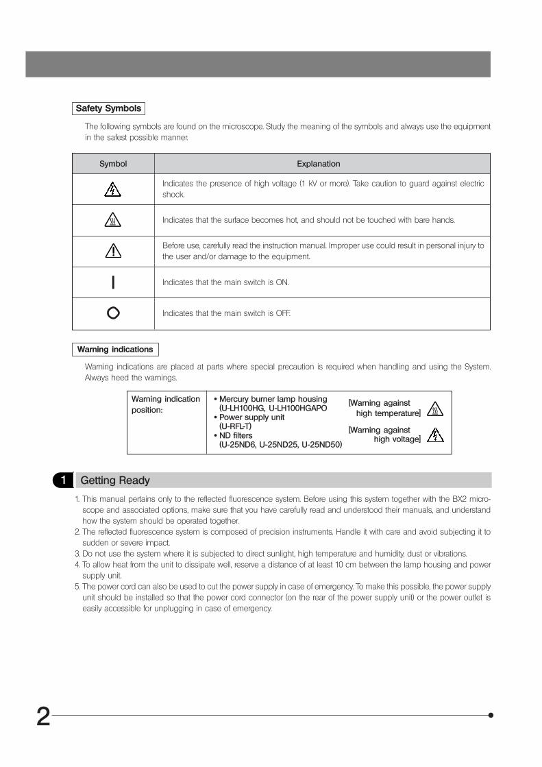
Safety Symbols
The following symbols are found on the microscope. Study the meaning of the symbols and always use the equipmentin the safest possible manner.
Indicates the presence of high voltage (1 kV or more). Take caution to guard against electricshock.
Indicates that the surface becomes hot, and should not be touched with bare hands.
Before use, carefully read the instruction manual. Improper use could result in personal injury tothe user and/or damage to the equipment.
Indicates that the main switch is ON.
Indicates that the main switch is OFF.
Warning indications
Warning indications are placed at parts where special precaution is required when handling and using the System.Always heed the warnings.
Warning indicationposition:
· Mercury burner lamp housing(U-LH100HG, U-LH100HGAPO
· Power supply unit(U-RFL-T)
· ND filters(U-25ND6, U-25ND25, U-25ND50)
[Warning againsthigh temperature]
[Warning againsthigh voltage]
1 Getting Ready
1. This manual pertains only to the reflected fluorescence system. Before using this system together with the BX2 micro-scope and associated options, make sure that you have carefully read and understood their manuals, and understandhow the system should be operated together.
2. The reflected fluorescence system is composed of precision instruments. Handle it with care and avoid subjecting it tosudden or severe impact.
3. Do not use the system where it is subjected to direct sunlight, high temperature and humidity, dust or vibrations.4. To allow heat from the unit to dissipate well, reserve a distance of at least 10 cm between the lamp housing and power
supply unit.5. The power cord can also be used to cut the power supply in case of emergency. To make this possible, the power supply
unit should be installed so that the power cord connector (on the rear of the power supply unit) or the power outlet iseasily accessible for unplugging in case of emergency.
3
1. To clean the lenses and other glass components, simply blow dirty away using a commercially available blower and wipegently using a piece of cleaning paper (or clean gauze).If a lens is stained with fingerprints or oil smudges, wipe it gauze slightly moistened with commercially available absolutealcohol.Since the absolute alcohol is highly flammable, it must be handled carefully.Be sure to keep it away from open flames or potential sources of electrical sparks --- for example, electricalequipment that is being switched on or off.Also remember to always use it only in a well-ventilated room.
2. With any part of the system other than glass components gets dirty, do not use organic solvents but wipe it with a cleancloth. If the part is extremely dirty, use a lint-free, soft cloth slightly moistened with a diluted neutral detergent.
3. Do not disassemble any part of the system. This could result in malfunctions or reduced performance.4. The mercury burner has a service life period of 300 hours (USH-103OL, HBO103W/2). When the hour counter on the
power supply unit indicates this value, set the main switch to “ ” (OFF) and wait for more than 10 minutes beforereplacing the mercury burner (Page 33). Unlike electric bulbs, the mercury burner seals high-pressure gas inside. If itcontinues to be used after the service life has expired, the glass tube may eventually explode due to accumulateddistortion.
5. When not using the microscope, be sure set the main switch to “ ” (OFF). After confirming that the lamp housing hascooled down sufficiently, cover the microscope with the dust cover for storage.
6. When disposing of the microscope, check the regulations and rules of your local government and be sure to observethem.
2 Maintenance and Storage
The following symbols are used to set off text in this instruction manual.: Indicates that failure to follow the instructions in the warning could result in bodily harm to theuser and/or damage to equipment (including objects in the vicinity of the equipment).
# : Indicates that failure to follow the instructions could result in damage to equipment.} : Indicates commentary (for ease of operation and maintenance).
3 Caution
If the system is used in a manner not specified by this manual, the safety of the user may be imperiled. In addition, thesystem equipment may also be damaged. Always use the system as outlined in this instruction manual.
4
I. REFLECTED FLUORESCENCE OBSERVATION
NOMENCLATURE
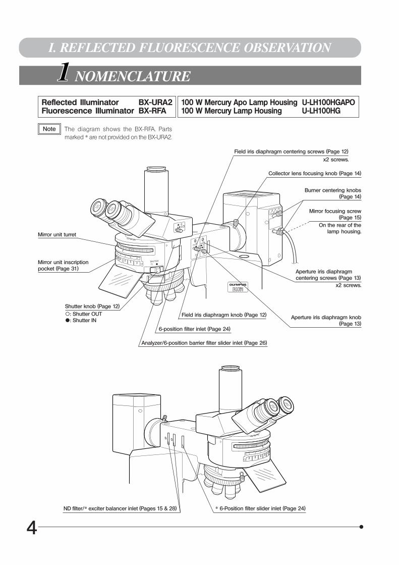
Reflected Illuminator BX-URA2Fluorescence Illuminator BX-RFA
Note The diagram shows the BX-RFA. Partsmarked * are not provided on the BX-URA2.
100 W Mercury Apo Lamp Housing U-LH100HGAPO100 W Mercury Lamp Housing U-LH100HG
Mirror unit turret
Mirror unit inscriptionpocket (Page 31)
Shutter knob (Page 12)\: Shutter OUT{: Shutter IN Aperture iris diaphragm knob
(Page 13)
Collector lens focusing knob (Page 14)
Burner centering knobs (Page 14)
Mirror focusing screw(Page 15)
On the rear of thelamp housing.
* 6-Position filter slider inlet (Page 24)
Aperture iris diaphragmcentering screws (Page 13)
x2 screws.
Field iris diaphragm centering screws (Page 12)
x2 screws.
Field iris diaphragm knob (Page 12)
6-position filter inlet (Page 24)
Analyzer/6-position barrier filter slider inlet (Page 26)
ND filter/* exciter balancer inlet (Pages 15 & 28)
1
3
23
4 5
6
5
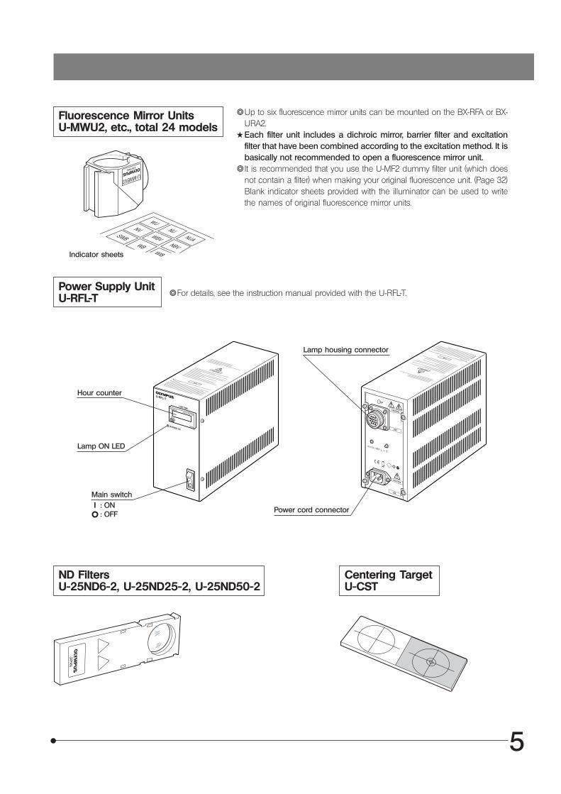
Fluorescence Mirror UnitsU-MWU2, etc., total 24 models
Indicator sheets
}Up to six fluorescence mirror units can be mounted on the BX-RFA or BX-URA2.
#Each filter unit includes a dichroic mirror, barrier filter and excitationfilter that have been combined according to the excitation method. It isbasically not recommended to open a fluorescence mirror unit.
}It is recommended that you use the U-MF2 dummy filter unit (which doesnot contain a filter) when making your original fluorescence unit. (Page 32)Blank indicator sheets provided with the illuminator can be used to writethe names of original fluorescence mirror units.
Power Supply UnitU-RFL-T
ND FiltersU-25ND6-2, U-25ND25-2, U-25ND50-2
Centering TargetU-CST
}For details, see the instruction manual provided with the U-RFL-T.
Hour counter
Lamp ON LED
Main switch
Lamp housing connector
Power cord connector I : ON : OFF
6
(Controls Used) (Page)
Start observation.
(P. 11)Set the main switch to “ I ” (ON) and wait for
the arc to stabilize.
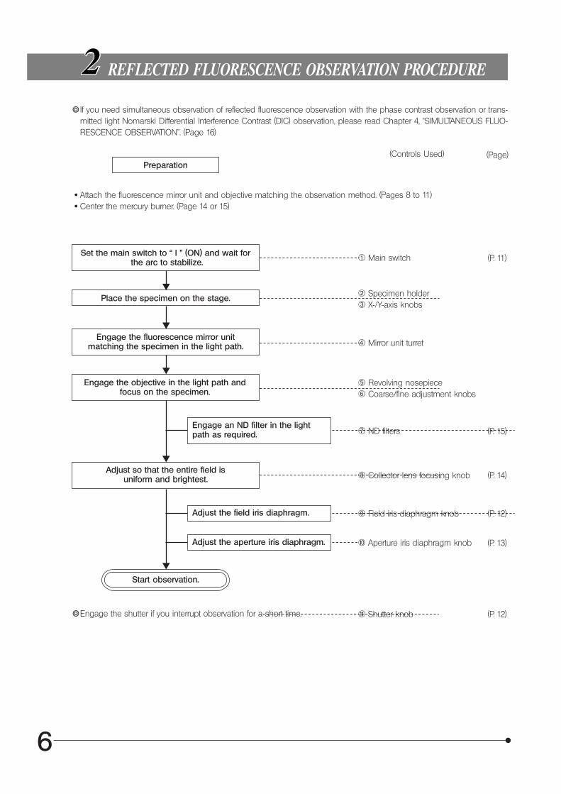
REFLECTED FLUORESCENCE OBSERVATION PROCEDURE
}If you need simultaneous observation of reflected fluorescence observation with the phase contrast observation or trans-mitted light Nomarski Differential Interference Contrast (DIC) observation, please read Chapter 4, “SIMULTANEOUS FLUO-RESCENCE OBSERVATION”. (Page 16)
Preparation
· Attach the fluorescence mirror unit and objective matching the observation method. (Pages 8 to 11) · Center the mercury burner. (Page 14 or 15)
@ Main switch
Place the specimen on the stage. ² Specimen holder³ X-/Y-axis knobs
Engage the fluorescence mirror unitmatching the specimen in the light path. | Mirror unit turret
Engage the objective in the light path andfocus on the specimen.
ƒ Revolving nosepiece… Coarse/fine adjustment knobs
Engage an ND filter in the lightpath as required.
Adjust so that the entire field isuniform and brightest.
† ND filters
‡ Collector lens focusing knob
Adjust the field iris diaphragm. Š Field iris diaphragm knob
Adjust the aperture iris diaphragm. ‰ Aperture iris diaphragm knob
}Engage the shutter if you interrupt observation for a short time. ‹ Shutter knob
(P. 15)
(P. 14)
(P. 12)
(P. 13)
(P. 12)
7
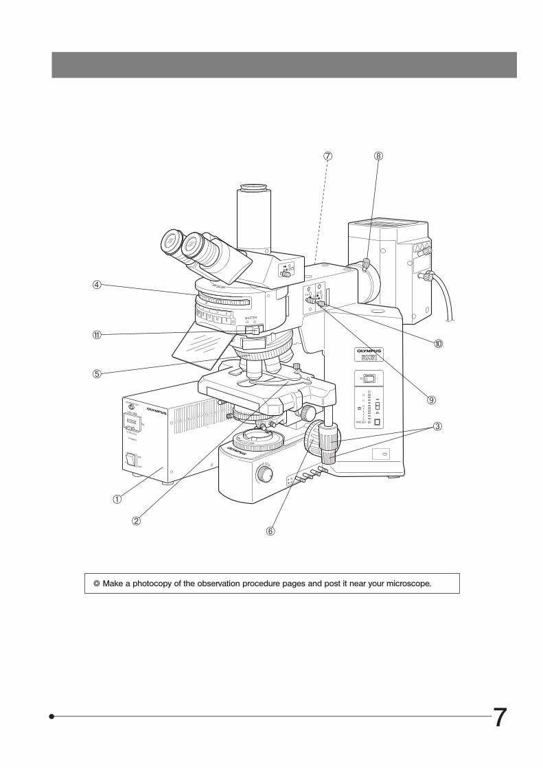
} Make a photocopy of the observation procedure pages and post it near your microscope.
³
@
²
|
ƒ
…
† ‡
Š
‰‹
8
USING THE CONTROLS
1 General Precautions for Observation
1. Make sure that the power cord and connecting cables are plugged in securely.2. If you perform only transmitted light phase contrast or transmitted light DIC observations, leave one cube position on the
turret empty. This allows for transmission of white light.The turret must always be set to one of the click position. If it is deviated from a click position, the cover may be deformedby heat.
3. Enlarge the field iris diaphragm so it just circumscribes the field of view. If decentered, center it using the Allen screwdriver.4. Always use immersion for oil immersion objectives.5. If you use an objective with correction collar such as the UPlanSApo40X, UPlanFLN60X, UPlanApo40X or PlanApo40X,
you can correct variations in cover glass thickness by adjusting the correction collar.
Correction procedure
If the cover glass thickness is known, match the correction collar to the cover glass thickness using the collar scaleprovided. If the thickness is not known, turn the collection collar and adjust the fine adjustment knob to where theimage is as sharp as possible.
6. Engage the shutter if you interrupt observation for a short time.(Turning the mercury burner ON and OFF repeatedly will significantly shorten the life span of the burner.)
7. Color fading of specimensThis system features high excitation light intensity to ensure bright observation of dark fluorescence specimens.In consequence, after long period of observations using high-power objectives, the colors of specimens will fade quickerthan usual, causing the view (contrast) of fluorescent images to deteriorate.In such a case, slightly reduce the excitation light intensity to slow color fading down and improve the fluorescenceimages.To reduce the excitation light intensity, use ND filters or aperture iris diaphragm as far as the observation is not affected oruse the shutter to limit the exposure of specimen to more than necessary light.Commercially-marketed color fading protection agent (DABCO, etc.) can also delay fading of specimen colors. The use offading protection agent is recommended especially when you perform high-magnification observations frequently.
#Remember that the fading protection agents cannot be used with certain kinds of specimens.
Select the fluorescence mirror unit which matches the fluorochrome in use.#Never mount or use the U-MBF3 brightfield mirror unit together with a with a mirror unit for fluorescence. The U-
MBF3 brightness is excessive and injury to the eyes could occur. If this type of mirror unit is to be used togetherwith a mirror unit for fluorescence, use the U-MBFL3 mirror unit equipped with a built-in ND filter or add a 3% NDfilter to the U-MBF3.
}Use according to the excitation wevelength:Olympus has prepared some sets of fluorescence mirror unit combined with appropriate filters which are variable de-pending on wavelengths.The wide-band (W) set is normally used. There may be cases, however, where superwide-band (SW) or Narrow-band (N)sets are recommendable.
2 Selecting the Fluorescence Mirror Unit
@Extremely weak fluorescence brightness(B- and G-excitation only):
Use the super-wide band (SW).}With the SWB, strong autofluorescence may reduce
image contrast.
² Specimens emitting strong autofluorescence: Use the narrow band (N).}The fluorescence bright is somewhat reduced.
9
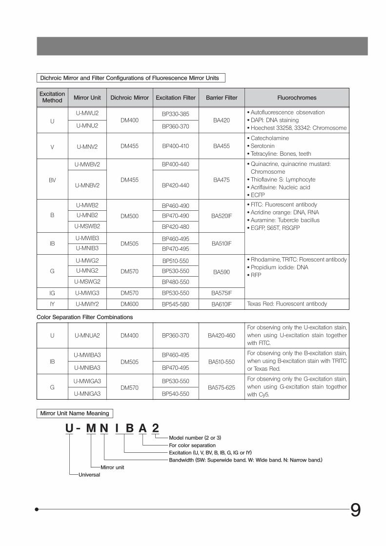
Dichroic Mirror and Filter Configurations of Fluorescence Mirror Units
ExcitationMethod Mirror Unit Dichroic Mirror Excitation Filter Barrier Filter Fluorochromes
· Autofluorescence observation· DAPI: DNA staining· Hoechest 33258, 33342: Chromosome
· Catecholamine· Serotonin· Tetracyline: Bones, teeth
· Quinacrine, quinacrine mustard:Chromosome
· Thioflavine S: Lymphocyte· Acriflavine: Nucleic acid· ECFP
· FITC: Fluorescent antibody· Acridine orange: DNA, RNA· Auramine: Tubercle bacillus· EGFP, S65T, RSGFP
· Rhodamine, TRITC: Florescent antibody· Propidium iodide: DNA· RFP
Texas Red: Fluorescent antibody
Color Separation Filter Combinations
For observing only the U-excitation stain,when using U-excitation stain togetherwith FITC.
For observing only the B-excitation stain,when using B-excitation stain with TRITCor Texas Red.
Mirror Unit Name Meaning
For color separation
U - M N I B A 2
Excitation (U, V, BV, B, IB, G, IG or IY)Bandwidth (SW: Superwide band. W: Wide band. N: Narrow band.)
Mirror unitUniversal
U
V
BV
B
IB
G
IG
IY
U U-MNUA2
IBU-MWIBA3
U-MNIBA3
DM400 BP360-370 BA420-460
DM505BP460-495
BA510-550BP470-495
U-MWU2DM400
BP330-385BA420
U-MNV2 DM455 BP400-410 BA455
U-MWBV2
DM455
BP400-440
BA475
U-MWB2
U-MNB2
U-MSWB2
DM500
BP460-490
BP470-490
BP420-480
BA520IF
U-MWIB3
U-MNIB3DM505
BP460-495
BP470-495BA510IF
U-MWG2
U-MNG2
U-MSWG2
DM570
BP510-550
BP530-550
BP480-550
BA590
U-MWIG3 DM570 BP530-550 BA575IF
U-MWIY2 DM600 BP545-580 BA610IF
U-MNU2 BP360-370
U-MNBV2 BP420-440
Model number (2 or 3)
For observing only the G-excitation stain,when using G-excitation stain togetherwith Cy5.
GU-MWIGA3
U-MNIGA3DM570
BP530-550BA575-625
BP540-550
10
ExcitationMethod Mirror Unit Dichroic Mirror Excitation Filter Barrier Filter Fluorochromes
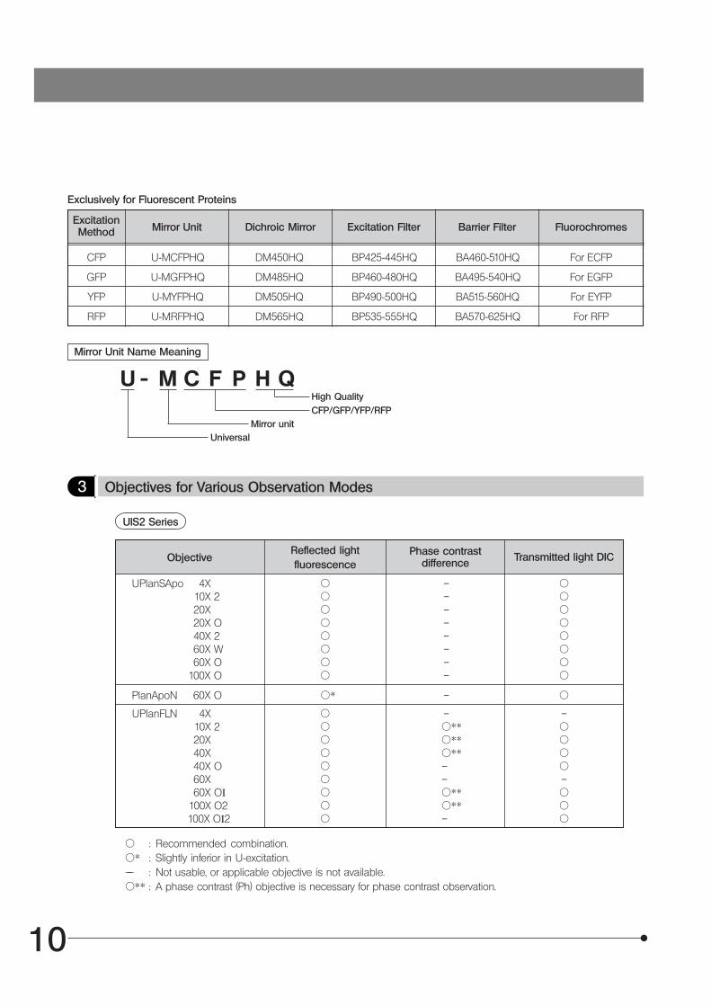
3 Objectives for Various Observation Modes
Exclusively for Fluorescent Proteins
Mirror Unit Name Meaning
U - M C F P H QHigh QualityCFP/GFP/YFP/RFP
Mirror unitUniversal
ObjectiveReflected lightfluorescence
Phase contrastdifference Transmitted light DIC
UPlanSApo 4X 10X 220X20X O 40X 260X W60X O
100X O
¦¦¦¦¦¦¦¦
– – – – – – – –
¦¦¦¦¦¦¦¦
CFP U-MCFPHQ DM450HQ BP425-445HQ BA460-510HQ For ECFP
GFP U-MGFPHQ DM485HQ BP460-480HQ BA495-540HQ For EGFP
YFP U-MYFPHQ DM505HQ BP490-500HQ BA515-560HQ For EYFP
RFP U-MRFPHQ DM565HQ BP535-555HQ BA570-625HQ For RFP
UIS2 Series
–¦¦¦¦–¦¦¦
¦ : Recommended combination.¦* : Slightly inferior in U-excitation.–– : Not usable, or applicable objective is not available.¦** : A phase contrast (Ph) objective is necessary for phase contrast observation.
PlanApoN 60X O
UPlanFLN 4X 10X 220X40X40X O60X60X OI
100X O2 100X OI2
– ¦
–¦**¦**¦**––¦**¦**–
¦¦¦¦¦¦¦¦¦
¦*
11
–¦¦¦¦¦
¦¦¦¦¦
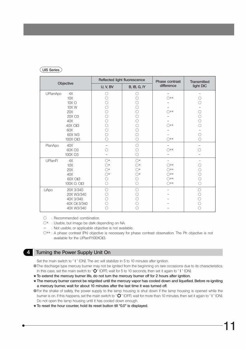
¦ : Recommended combination.¦* : Usable, but image be dark depending on NA.–– : Not usable, or applicable objective is not available.¦** : A phase contrast (Ph) objective is necessary for phase contrast observation. The Ph objective is not
available for the UPlanFI100XOI3.
4 Turning the Power Supply Unit On
Set the main switch to “ I ” (ON). The arc will stabilize in 5 to 10 minutes after ignition.}The discharge type mercury burner may not be ignited from the beginning on rare occasions due to its characteristics.
In this case, set the main switch to “ ” (OFF), wait for 5 to 10 seconds, then set it again to “ I ” (ON).#To extend the mercury burner life, do not turn the mercury burner off for 2 hours after ignition.#The mercury burner cannot be reignited until the mercury vapor has cooled down and liquefied. Before re-igniting
a mercury burner, wait for about 10 minutes after the last time it was turned off.}For the shake of safety, the power supply to the lamp housing is shut down if the lamp housing is opened while the
burner is on. If this happens, set the main switch to “ ” (OFF), wait for more than 10 minutes, then set it again to “ I ” (ON).Do not open the lamp housing until it has cooled down enough.
#To reset the hour counter, hold its reset button till “0.0” is displayed.
ObjectiveReflected light fluorescence
U, V, BV B, IB, G, IYPhase contrast
differenceTransmitted
light DIC
UPlanApo 4X10X10X O10X W20X
20X O340X
40X OI3 60X
60X W3 100X OI3
PlanApo 40X 60X O3
100X O3
UPlanFI 4X10X20X40X
60X OI3 100X O, OI3
UApo 20X 3/340 20X W3/340
40X 3/340 40X OI 3/340 40X W3/340
¦¦¦¦¦¦¦¦¦¦¦
¦¦¦¦¦¦¦¦¦¦¦
–¦** – –¦** – –¦** – –¦**
–¦¦–¦¦¦¦–¦¦
–¦–
¦¦¦
–¦** –
–¦–
¦*¦*¦*¦*¦¦
¦*¦*¦*¦*¦¦
–¦**¦**¦**¦**¦**
¦¦¦¦¦
¦¦¦¦¦
–––––
UIS Series
12
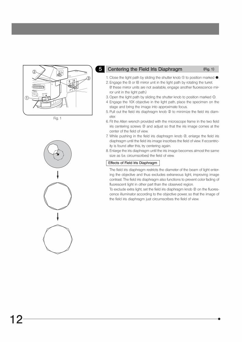
Fig. 1
5 Centering the Field Iris Diaphragm (Fig. 1)
1. Close the light path by sliding the shutter knob @ to position marked {.2. Engage the B or IB mirror unit in the light path by rotating the turret.
(If these mirror units are not available, engage another fluorescence mir-ror unit in the light path.)
3. Open the light path by sliding the shutter knob to position marked \.4 Engage the 10X objective in the light path, place the specimen on the
stage and bring the image into approximate focus.5. Pull out the field iris diaphragm knob ² to minimize the field iris diam-
eter.6. Fit the Allen wrench provided with the microscope frame in the two field
iris centering screws ³ and adjust so that the iris image comes at thecenter of the field of view.
7. While pushing in the field iris diaphragm knob ², enlarge the field irisdiaphragm until the field iris image inscribes the field of view. If eccentric-ity is found after this, try centering again.
8. Enlarge the iris diaphragm until the iris image becomes almost the samesize as (i.e. circumscribes) the field of view.
Effects of Field Iris Diaphragm
The field iris diaphragm restricts the diameter of the beam of light enter-ing the objective and thus excludes extraneous light, improving imagecontrast. The field iris diaphragm also functions to prevent color fading offluorescent light in other part than the observed region.To exclude extra light, set the field iris diaphragm knob ² on the fluores-cence illuminator according to the objective power, so that the image ofthe field iris diaphragm just circumscribes the field of view.
@
²³
13
Fig. 2
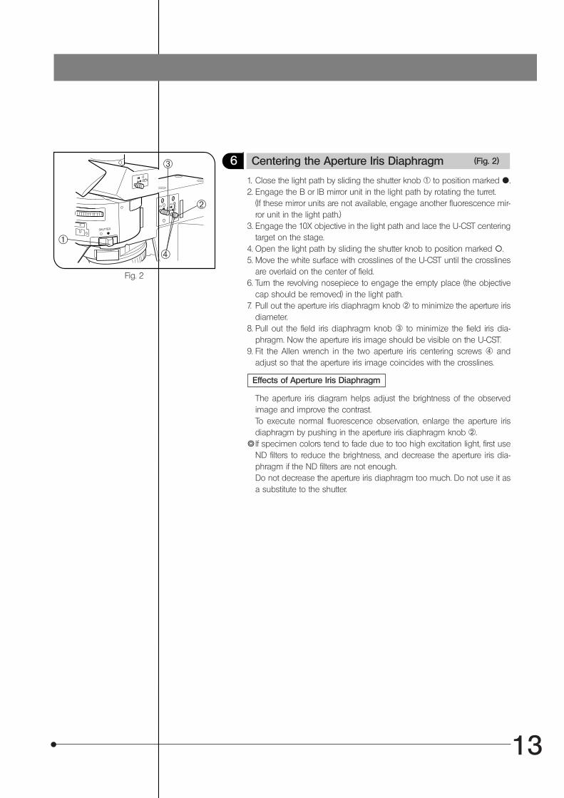
6 Centering the Aperture Iris Diaphragm (Fig. 2)
1. Close the light path by sliding the shutter knob @ to position marked {.2. Engage the B or IB mirror unit in the light path by rotating the turret.
(If these mirror units are not available, engage another fluorescence mir-ror unit in the light path.)
3. Engage the 10X objective in the light path and lace the U-CST centeringtarget on the stage.
4. Open the light path by sliding the shutter knob to position marked \.5. Move the white surface with crosslines of the U-CST until the crosslines
are overlaid on the center of field.6. Turn the revolving nosepiece to engage the empty place (the objective
cap should be removed) in the light path.7. Pull out the aperture iris diaphragm knob ² to minimize the aperture iris
diameter.8. Pull out the field iris diaphragm knob ³ to minimize the field iris dia-
phragm. Now the aperture iris image should be visible on the U-CST.9. Fit the Allen wrench in the two aperture iris centering screws | and
adjust so that the aperture iris image coincides with the crosslines.
Effects of Aperture Iris Diaphragm
The aperture iris diagram helps adjust the brightness of the observedimage and improve the contrast.To execute normal fluorescence observation, enlarge the aperture irisdiaphragm by pushing in the aperture iris diaphragm knob ².
}If specimen colors tend to fade due to too high excitation light, first useND filters to reduce the brightness, and decrease the aperture iris dia-phragm if the ND filters are not enough.Do not decrease the aperture iris diaphragm too much. Do not use it asa substitute to the shutter.
@
²
³
|
14
Fig. 3
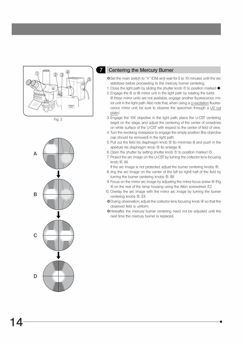
7 Centering the Mercury Burner
}Set the main switch to “ I ” (ON) and wait for 5 to 10 minutes until the arcstabilizes before proceeding to the mercury burner centering.
1. Close the light path by sliding the shutter knob @ to position marked {.2. Engage the B or IB mirror unit in the light path by rotating the turret.
(If these mirror units are not available, engage another fluorescence mir-ror unit in the light path. Also note that, when using a U-excitation fluores-cence mirror unit, be sure to observe the specimen through a UV cutplate.)
3. Engage the 10X objective in the light path, place the U-CST centeringtarget on the stage, and adjust the centering of the center of crosslineson white surface of the U-CST with respect to the center of field of view.
4. Turn the revolving nosepiece to engage the empty position (the objectivecap should be removed) in the light path.
5. Pull out the field iris diaphragm knob ² (to minimize it) and push in theaperture iris diaphragm knob ³ (to enlarge it).
6. Open the shutter by setting shutter knob @ to position marked \.7. Project the arc image on the U-CST by turning the collector lens focusing
knob |. (A)If the arc image is not protected, adjust the burner centering knobs ƒ.
8. ring the arc image on the center of the left (or right) half of the field byturning the burner centering knobs ƒ. (B)
9. Focus on the mirror arc image by adjusting the mirror focus screw … (Fig4) on the rear of the lamp housing using the Allen screwdriver. (C)Overlay the arc image with the mirror arc image by turning the burnercentering knobs ƒ. (D)
}During observation, adjust the collector lens focusing knob | so that theobserved field is uniform.
}Hereafter, the mercury burner centering need not be adjusted until thenext time the mercury burner is replaced.
@ ² ³ |
ƒ
A
B
C
D
10.
15
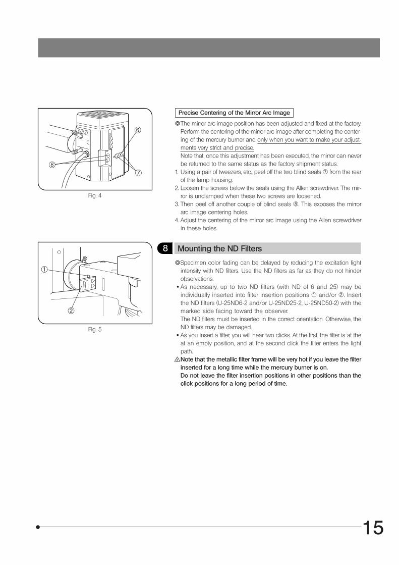
Precise Centering of the Mirror Arc Image
Fig. 4
}The mirror arc image position has been adjusted and fixed at the factory.Perform the centering of the mirror arc image after completing the center-ing of the mercury burner and only when you want to make your adjust-ments very strict and precise.Note that, once this adjustment has been executed, the mirror can neverbe returned to the same status as the factory shipment status.
1. Using a pair of tweezers, etc., peel off the two blind seals † from the rearof the lamp housing.
2. Loosen the screws below the seals using the Allen screwdriver. The mir-ror is unclamped when these two screws are loosened.
3. Then peel off another couple of blind seals ‡. This exposes the mirrorarc image centering holes.
4. Adjust the centering of the mirror arc image using the Allen screwdriverin these holes.
Fig. 5
8 Mounting the ND Filters
}Specimen color fading can be delayed by reducing the excitation lightintensity with ND filters. Use the ND filters as far as they do not hinderobservations.
· As necessary, up to two ND filters (with ND of 6 and 25) may beindividually inserted into filter insertion positions @ and/or ². Insertthe ND filters (U-25ND6-2 and/or U-25ND25-2, U-25ND50-2) with themarked side facing toward the observer.The ND filters must be inserted in the correct orientation. Otherwise, theND filters may be damaged.
· As you insert a filter, you will hear two clicks. At the first, the filter is at theat an empty position, and at the second click the filter enters the lightpath.Note that the metallic filter frame will be very hot if you leave the filterinserted for a long time while the mercury burner is on.Do not leave the filter insertion positions in other positions than theclick positions for a long period of time.
@
²
…
†‡
16
SIMULTANEOUS FLUORESCENCE OBSERVATIONS
}By properly combining equipment, this system can be used in transmitted light brightfield observation, transmitted phasecontrast observation and transmitted light DIC observation in addition to the reflected fluorescence observation. Withspecimens that fade rapidly, fading can be minimized by initially using transmitted light phase contrast or transmitted lightDIC observation for positioning. Reflected fluorescence observation can also be executed simultaneously with phasecontrast or DIC observation, making it easy to tell which portion of the specimen is fluorescing.
1 Simultaneous Reflected Fluorescence and Phase Contrast Observations
The phase contrast observation requires a phase contrast condenser (U-PCD2) or a universal condenser (U-UCD8) anda Ph objective.
1. Engage a dummy mirror unit (or an empty position on the turret) in the light path.2. Rotate the phase contrast turret to show the same number as the Ph number shown on the objective.3. Adjust the optical axis between the ring sit and phase plate by centering them.4. Engage the mirror unit corresponding to the desired excitation into the light path and open the shutter.5. Adjust the transmitted light for the best balance of fluorescence and phase contrast brightness, and you are ready for
observation.}Use ND filters or the light intensity control lever on the microscope base to adjust the transmitted light intensity.}For details on using phase contrast observation, refer to the instruction manual provided with the phase contrast con-
denser or universal condenser.
Simultaneous Reflected Fluorescence and Transmitted Light Nomarski DifferentialInterference Contrast (DIC) Observations
The transmitted light Nomarski DIC observation requires the following accessories; 1) universal condenser (U-UCD8); 2)transmitted light DIC slider (U-DICT, U-DICTS, U-DICTHR or U-DICTHC); 2) analyzer (U-AN or U-AN360-3); 6- or 7-positionrevolving nosepiece for DIC (U-D6RE or U-D7RE).
}In order for reflected fluorescence to be effective in the simultaneous observation, insert the analyzer (U-AN or U-AN360-3) into the analyzer inlet slot above the dichroic mirror on the illuminator.Do not insert the U-ANT analyzer in the transmitted light DIC slider, for this will dim the fluorescence observation imageand cause the analyzer to be burnt.
1. Engage the dummy mirror unit (or an empty position on the turret) in the light path.2. Adjust the polarizer on the universal condenser to the “crossed Nicol” (complete extinction) status.3. Insert the transmitted light DIC slider into the position provided on the nosepiece.4. Rotate the turret on the universal condenser to select the Nomarski prism matching the objective to be used for observa-
tion.5. Engage the objective to be used in the light path.6. Place the specimen on the stage and focus on the specimen.7. Adjust the field iris diaphragm of the transmitted light illumination unit (built into the microscope base) and the aperture iris
diaphragm of the universal condenser.8. Turn the prism movement knob on the transmitted light DIC slider to adjust contrast of the DIC image.9. Engage the mirror unit corresponding to the desired excitation in the light path and opent the shutter.
Adjust the transmitted light for optimum fluorescence and DIC image brightness.}For details on the transmitted light DIC observation, refer to the instruction manual provided with the U-UCD8 transmitted
light universal condenser.
2
10.
Notes
}We recommend the use of the highly wear-resistant U-ANH analyzer-slider instead of the U-AN analyzer when you arefrequently switching between reflected fluorescence observation and transmitted light Nomarski DIC observation andneed to use both observations simultaneously.
}However, if you are frequency switching between reflected fluorescence observation and transmitted light Nomarski DICobservation but you do not need to use both simultaneously, then it will be more convenient for you to use the M-DICT3DIC mirror unit instead of an analyzer (U-AN or U-ANH). This facilitates the switching operation because the analyzersimultaneously enters the light path when the fluorescence mirror unit is switched to the DIC mirror unit.
17
TROUBLESHOOTING GUIDE
Cause Remedy Page
4
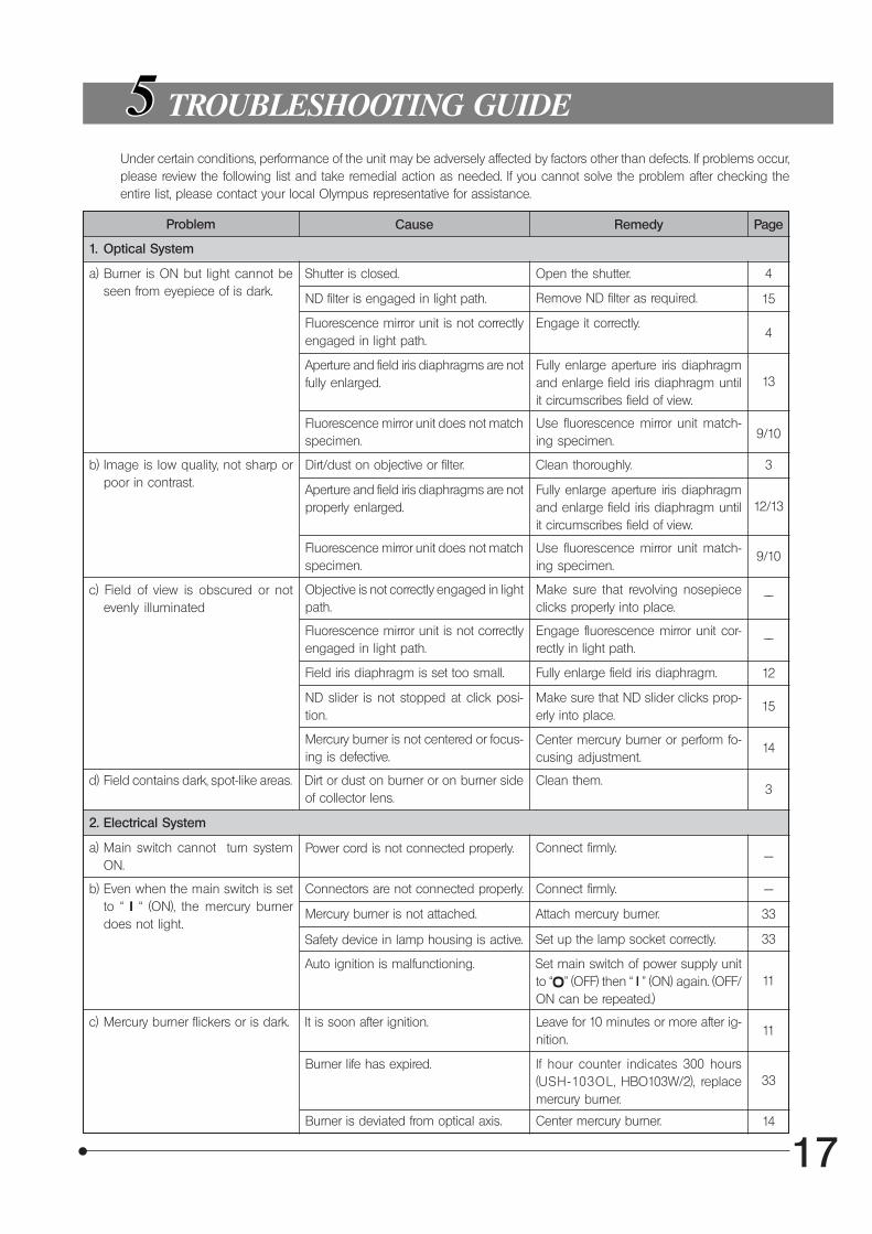
Under certain conditions, performance of the unit may be adversely affected by factors other than defects. If problems occur,please review the following list and take remedial action as needed. If you cannot solve the problem after checking theentire list, please contact your local Olympus representative for assistance.
a) Burner is ON but light cannot beseen from eyepiece of is dark.
Shutter is closed. Open the shutter.
ND filter is engaged in light path. Remove ND filter as required.
Fluorescence mirror unit is not correctlyengaged in light path.
Engage it correctly.
Aperture and field iris diaphragms are notfully enlarged.
Fully enlarge aperture iris diaphragmand enlarge field iris diaphragm untilit circumscribes field of view.
Fluorescence mirror unit does not matchspecimen.
Use fluorescence mirror unit match-ing specimen.
b) Image is low quality, not sharp orpoor in contrast.
Dirt/dust on objective or filter. Clean thoroughly.
Aperture and field iris diaphragms are notproperly enlarged.
Fully enlarge aperture iris diaphragmand enlarge field iris diaphragm untilit circumscribes field of view.
Fluorescence mirror unit does not matchspecimen.
Use fluorescence mirror unit match-ing specimen.
c) Field of view is obscured or notevenly illuminated
Objective is not correctly engaged in lightpath.
Make sure that revolving nosepiececlicks properly into place.
Fluorescence mirror unit is not correctlyengaged in light path.
Engage fluorescence mirror unit cor-rectly in light path.
Field iris diaphragm is set too small. Fully enlarge field iris diaphragm.
ND slider is not stopped at click posi-tion.
Make sure that ND slider clicks prop-erly into place.
Mercury burner is not centered or focus-ing is defective.
Center mercury burner or perform fo-cusing adjustment.
d) Field contains dark, spot-like areas. Dirt or dust on burner or on burner sideof collector lens.
Clean them.
a) Main switch cannot turn systemON.
Power cord is not connected properly. Connect firmly.
b) Even when the main switch is setto “ I “ (ON), the mercury burnerdoes not light.
Connectors are not connected properly. Connect firmly.
Mercury burner is not attached. Attach mercury burner.
Safety device in lamp housing is active. Set up the lamp socket correctly.
Auto ignition is malfunctioning. Set main switch of power supply unitto “ ” (OFF) then “ I ” (ON) again. (OFF/ON can be repeated.)
c) Mercury burner flickers or is dark. It is soon after ignition. Leave for 10 minutes or more after ig-nition.
Burner life has expired. If hour counter indicates 300 hours(USH-103OL , HBO103W/2), replacemercury burner.
Burner is deviated from optical axis. Center mercury burner.
15
4
13
9/10
3
12/13
9/10
––
––
12
15
14
3
---
---
33
33
11
11
33
14
Problem
1. Optical System
2. Electrical System

18
SPECTRAL CHARACTERISTICS OF FILTERS1. U-excitation (Wide band)
2. U-excitation (Narrow band)
3. V-excitation (Narrow band)
4. BV-excitation (Wide band)
5. BV-excitation (Narrow band)
6. B-excitation (Wide band)
U-MWU2
U-MNU2
U-MNV2
U-MWBV2
U-MNBV2
U-MWB2
Tran
smitt
ance
%
Wavelength (nm)
Tran
smitt
ance
%
Wavelength (nm)
Tran
smitt
ance
%
Tran
smitt
ance
%
Tran
smitt
ance
%
Tran
smitt
ance
%
Wavelength (nm)
Wavelength (nm)
Wavelength (nm)
Wavelength (nm)
19
100
400 600 8000
BP460-495
BA510IF
DM505
100
400 600 8000
BP470-495
BA510IF
DM505
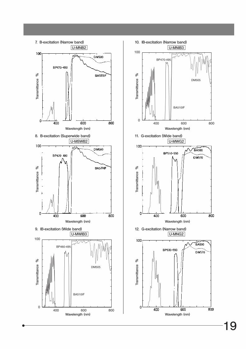
7. B-excitation (Narrow band)
8. B-excitation (Superwide band)
9. IB-excitation (Wide band)
10. IB-excitation (Narrow band)
11. G-excitation (Wide band)
12. G-excitation (Narrow band)
U-MNB2
U-MSWB2
U-MWIB3
U-MNIB3
U-MWG2
U-MNG2
Tran
smitt
ance
%
Wavelength (nm)
Tran
smitt
ance
%
Wavelength (nm)
Tran
smitt
ance
%
Tran
smitt
ance
%
Tran
smitt
ance
%
Wavelength (nm)
Wavelength (nm)
Wavelength (nm)
Tran
smitt
ance
%
Wavelength (nm)
20
100
400 600 8000
BA575IF
BP530-550
DM570
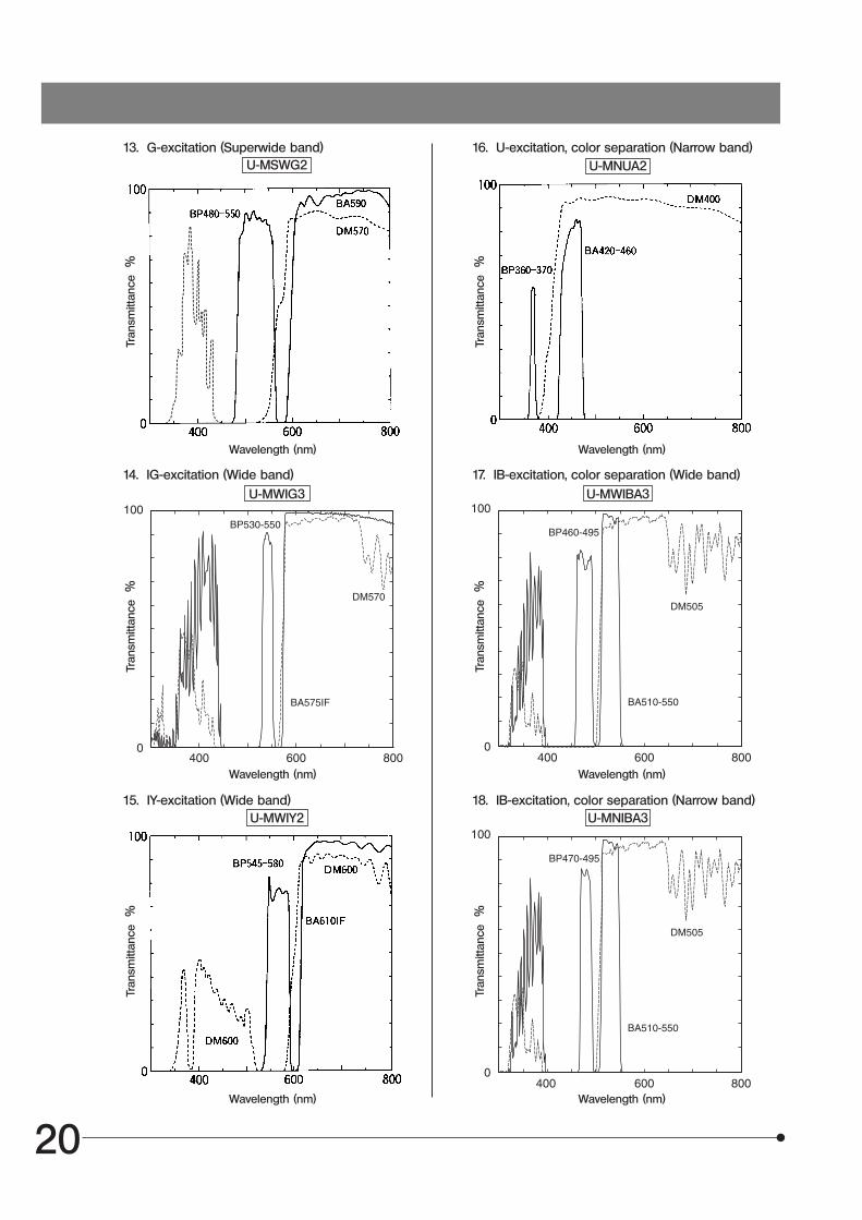
13. G-excitation (Superwide band)
14. IG-excitation (Wide band)
15. IY-excitation (Wide band)
16. U-excitation, color separation (Narrow band)
17. IB-excitation, color separation (Wide band)
18. IB-excitation, color separation (Narrow band)
U-MSWG2
U-MWIG3
U-MWIY2
U-MNUA2
U-MWIBA3
U-MNIBA3
100
400 600 8000
BA510-550
BP460-495
DM505
100
400 600 8000
BP470-495
BA510-550
DM505
Tran
smitt
ance
%
Tran
smitt
ance
%
Tran
smitt
ance
%
Wavelength (nm)
Wavelength (nm)
Wavelength (nm)
Tran
smitt
ance
%
Tran
smitt
ance
%
Wavelength (nm)Wavelength (nm)
Tran
smitt
ance
%
Wavelength (nm)
21
400
100
0450 500 550 600
BA515-560HQBA515-560HQ
BP490-500HQDM505HQ
400
100
0450 500 550 600
DM485HQBP460-480HQ
BA495-540HQ
400
100
0450 500 550 600
BA460-510HQ
BP425-445HQDM450HQ
100
400 600 8000
BA575-625
BP530-550
DM570
100
400 600 8000
BP540-550
BA575-625
DM570
100
400 600 8000
BP535-555HQ
BA570-625HQ
DM565HQ
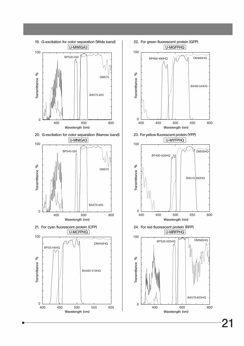
19. G-excitation for color separation (Wide band)
20. G-excitation for color separation (Narrow band)
21. For cyan fluorescent protein (CFP)
22. For green fluorescent protein (GFP)
23. For yellow fluorescent protein (YFP)
24. For red fluorescent protein (RFP)
U-MWIGA3
U-MNIGA3
U-MCFPHQ
U-MGFPHQ
U-MYFPHQ
U-MRFPHQ
Tran
smitt
ance
%
Wavelength (nm)
Tran
smitt
ance
%
Wavelength (nm)
Tran
smitt
ance
%
Tran
smitt
ance
%
Tran
smitt
ance
%
Tran
smitt
ance
%
Wavelength (nm)
Wavelength (nm)
Wavelength (nm)
Wavelength (nm)
22
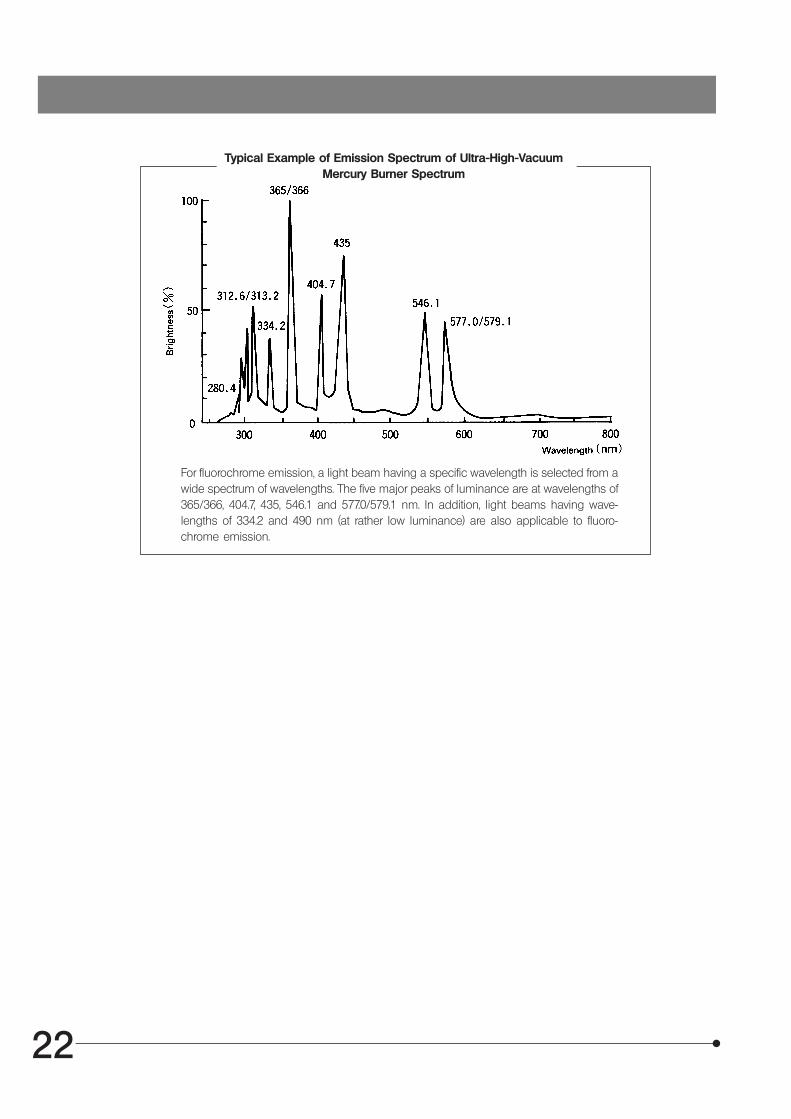
Typical Example of Emission Spectrum of Ultra-High-VacuumMercury Burner Spectrum
For fluorochrome emission, a light beam having a specific wavelength is selected from awide spectrum of wavelengths. The five major peaks of luminance are at wavelengths of365/366, 404.7, 435, 546.1 and 577.0/579.1 nm. In addition, light beams having wave-lengths of 334.2 and 490 nm (at rather low luminance) are also applicable to fluoro-chrome emission.
23
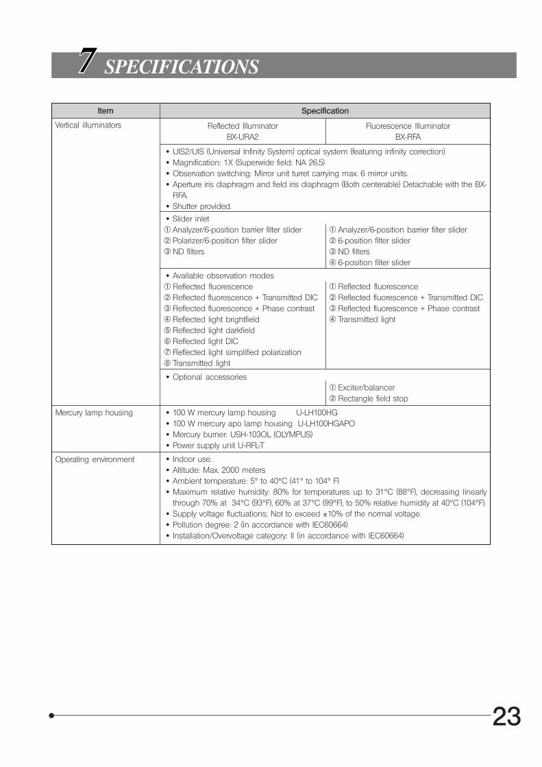
Item Specification
SPECIFICATIONS
Vertical illuminators Reflected IlluminatorBX-URA2
Fluorescence IlluminatorBX-RFA
· UIS2/UIS (Universal Infinity System) optical system (featuring infinity correction) · Magnification: 1X (Superwide field: NA 26.5) · Observation switching: Mirror unit turret carrying max. 6 mirror units. · Aperture iris diaphragm and field iris diaphragm (Both centerable) Detachable with the BX-
RFA. · Shutter provided.
· Slider inlet@ Analyzer/6-position barrier filter slider² Polarizer/6-position filter slider³ ND filters
@ Analyzer/6-position barrier filter slider² 6-position filter slider³ ND filters| 6-position filter slider
· Available observation modes@ Reflected fluorescence² Reflected fluorescence + Transmitted DIC³ Reflected fluorescence + Phase contrast| Reflected light brightfieldƒ Reflected light darkfield… Reflected light DIC† Reflected light simplified polarization‡ Transmitted light
@ Reflected fluorescence² Reflected fluorescence + Transmitted DIC³ Reflected fluorescence + Phase contrast| Transmitted light
· Optional accessories@ Exciter/balancer² Rectangle field stop
Mercury lamp housing · 100 W mercury lamp housing U-LH100HG · 100 W mercury apo lamp housing U-LH100HGAPO · Mercury burner: USH-103OL (OLYMPUS) · Power supply unit U-RFL-T
Operating environment · Indoor use. · Altitude: Max. 2000 meters · Ambient temperature: 5° to 40°C (41° to 104° F) · Maximum relative humidity: 80% for temperatures up to 31°C (88°F), decreasing linearly
through 70% at 34°C (93°F), 60% at 37°C (99°F), to 50% relative humidity at 40°C (104°F). · Supply voltage fluctuations; Not to exceed ±10% of the normal voltage. · Pollution degree: 2 (in accordance with IEC60664) · Installation/Overvoltage category: II (in accordance with IEC60664)
24
OPTIONAL MODULES
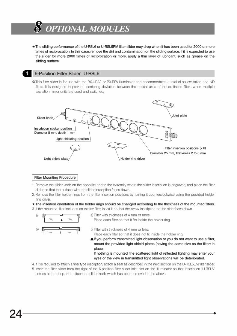
1 6-Position Filter Slider U-RSL6
}This filter slider is for use with the BX-URA2 or BX-RFA illuminator and accommodates a total of six excitation and NDfilters. It is designed to prevent centering deviation between the optical axes of the excitation filters when multipleexcitation mirror units are used and switched.
Filter Mounting Procedure
Slider knob
1. Remove the slider knob on the opposite end to the extremity where the slider inscription is engraved, and place the filterslider so that the surface with the slider inscription faces down.
2. Remove the filter holder rings from the filter insertion positions by turning it counterclockwise using the provided holderring driver.
#The insertion orientation of the holder rings should be changed according to the thickness of the mounted filters.3. If the mounted filter includes an exciter filter, insert it so that the arrow inscription on the side faces down.
a) Filter with thickness of 4 mm or more:Place each filter so that it fits inside the holder ring.
b) Filter with thickness of 4 mm or less:Place each filter so that it does not fit inside the holder ring.If you perform transmitted light observation or you do not want to use a filter,mount the provided light shield plates (having the same size as the filter) inplace.If nothing is mounted, the scattered light of reflected lighting may enter youreyes or the view in transmitted light observations will be deteriorated.
4. If it is required to attach a filter type inscription, attach a seal as described in the next section on the U-RSL6EM filter slider.5. Insert the filter slider from the right of the 6-position filter slider inlet slot on the illuminator so that inscription “U-RSL6”
comes at the deep, then attach the slider knob which has been removed in the above.
Inscription sticker position
Light shielding position
Light shield plate
Filter insertion positions (x 6)
Diameter 8 mm, depth 1 mm
Diameter 25 mm, Thickness 2 to 6 mm
Joint plate
Holder ring driver
a)
b)
#The sliding performance of the U-RSL6 or U-RSL6RM filter slider may drop when it has been used for 2000 or moretimes of reciprocation. In this case, remove the dirt and contamination on the sliding surface. If it is expected to usethe slider for more 2000 times of reciprocation or more, apply a thin layer of lubricant, such as grease on thesliding surface.
25
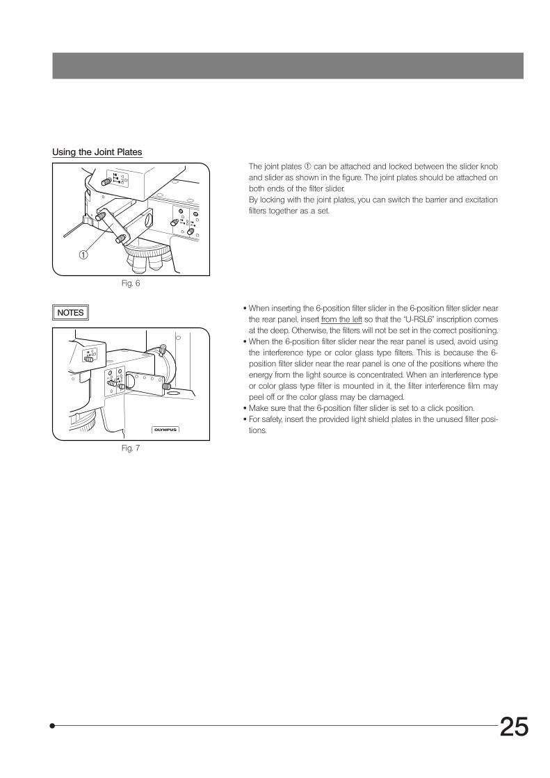
Using the Joint Plates
The joint plates @ can be attached and locked between the slider knoband slider as shown in the figure. The joint plates should be attached onboth ends of the filter slider.By locking with the joint plates, you can switch the barrier and excitationfilters together as a set.
Fig. 6
NOTES · When inserting the 6-position filter slider in the 6-position filter slider nearthe rear panel, insert from the left so that the “U-RSL6” inscription comesat the deep. Otherwise, the filters will not be set in the correct positioning.
· When the 6-position filter slider near the rear panel is used, avoid usingthe interference type or color glass type filters. This is because the 6-position filter slider near the rear panel is one of the positions where theenergy from the light source is concentrated. When an interference typeor color glass type filter is mounted in it, the filter interference film maypeel off or the color glass may be damaged.
· Make sure that the 6-position filter slider is set to a click position. · For safety, insert the provided light shield plates in the unused filter posi-
tions.
Fig. 7
@
26
2 6-Position Barrier Filter Slider U-RSL6EM
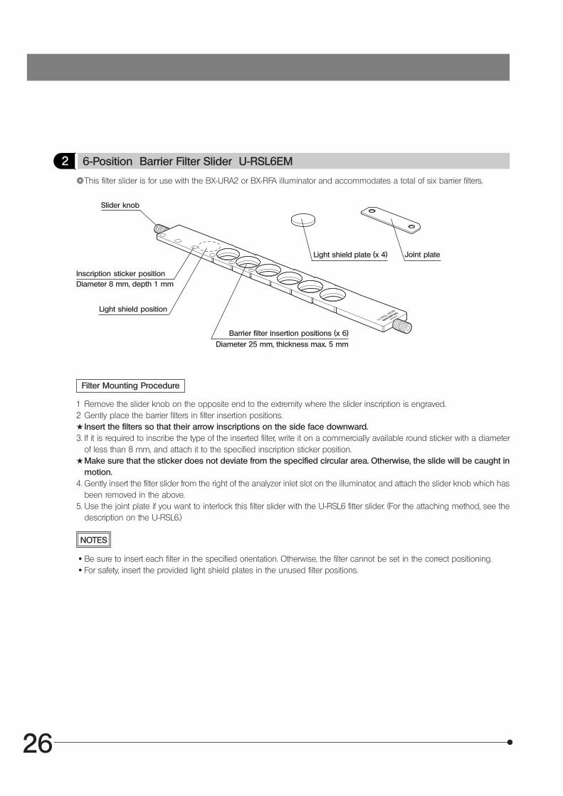
}This filter slider is for use with the BX-URA2 or BX-RFA illuminator and accommodates a total of six barrier filters.
Slider knob
Filter Mounting Procedure
1 Remove the slider knob on the opposite end to the extremity where the slider inscription is engraved.2 Gently place the barrier filters in filter insertion positions.#Insert the filters so that their arrow inscriptions on the side face downward.3. If it is required to inscribe the type of the inserted filter, write it on a commercially available round sticker with a diameter
of less than 8 mm, and attach it to the specified inscription sticker position.#Make sure that the sticker does not deviate from the specified circular area. Otherwise, the slide will be caught in
motion.4. Gently insert the filter slider from the right of the analyzer inlet slot on the illuminator, and attach the slider knob which has
been removed in the above.5. Use the joint plate if you want to interlock this filter slider with the U-RSL6 fitter slider. (For the attaching method, see the
description on the U-RSL6.)
Inscription sticker positionDiameter 8 mm, depth 1 mm
Light shield position
Barrier filter insertion positions (x 6)
Joint plate
Diameter 25 mm, thickness max. 5 mm
NOTES
· Be sure to insert each filter in the specified orientation. Otherwise, the filter cannot be set in the correct positioning. · For safety, insert the provided light shield plates in the unused filter positions.
Light shield plate (x 4)
27
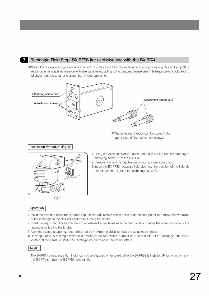
3 Rectangle Field Stop BX-RFSS (for exclusive use with the BX-RFA)
}When fluorescence images are recorded with the TV camera for observation or image processing, this unit projects arectangular iris diaphragm image with size variable according to the captured image size. This helps prevent color fadingof specimen due to other reasons than image capturing.
Installation Procedure (Fig. 8)
Clamping screw hole
1. Using the Allen screwdriver, loosen and take out the field iris diaphragmclamping screw @. of the BX-RFA.
2. Remove the field iris diaphragm by puling it out toward you.3. Insert the BX-RFSS rectangle field stop into the position of the field iris
diaphragm, then tighten the clamping screw @.
Fig. 8
Operation
1. Insert the provided adjustment knobs into the two adjustment screw holes near the front panel, and move the two sidesof the rectangle to the desired position by turning the knobs.
2. Insert the adjustment knobs into the two adjustment screw holes near the rear panel. and move the other two sides of therectangle by turning the knobs.
3. After the desired shape has been obtained by moving the sides, remove the adjustment knobs.}Rectangle area: A rectangle which circumscribes the field with a number of 22 (the center of the rectangle should be
located at the center of field). The rectangle iris diaphragm cannot be rotated.
Adjustment screwsAdjustment knobs (x 2)
@
NOTE
The BX-RFA fluorescence illuminator cannot be attached or removed while the BX-RFSS is installed. IF you want to installthe BX-RFA, remove the BX-RFSS temporarily.
}The adjustment knobs can be stored in theupper slots of the adjustment screws.
28
Fig. 9
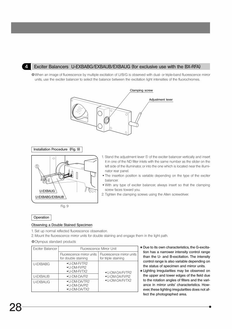
4 Exciter Balancers U-EXBABG/EXBAUB/EXBAUG (for exclusive use with the BX-RFA)
}When an image of fluorescence by multiple excitation of U/B/G is observed with dual- or triple-band fluorescence mirrorunits, use the exciter balancer to select the balance between the excitation light intensities of the fluorochromes.
Clamping screw
Installation Procedure (Fig. 9)
1. Stand the adjustment lever @ of the exciter balancer vertically and insertit in one of the ND filter inlets with the same number as the slider on theleft side of the illuminator, or into the one which is located near the illumi-nator rear panel.
· The insertion position is variable depending on the type of the exciterbalancer.
· With any type of exciter balancer, always insert so that the clampingscrew faces toward you.
2. Tighten the clamping screws using the Allen screwdriver.
Operation
Observing a Double Stained Specimen
#Due to its own characteristics, the G-excita-tion has a narrower intensity control rangethan the U- and B-excitation. The intensitycontrol range is also variable depending onthe status of specimen and mirror units.
#Lighting irregularities may be observed onthe upper and lower edges of the field dueto the rotation angles of filters and the vari-ance in mirror units’ characteristics. How-ever, these lighting irregularities does not af-fect the photographed area.
1. Set up normal reflected fluorescence observation.2. Mount the fluorescence mirror units for double staining and engage them in the light path.
}Olympus standard products
Fluorescence Mirror UnitExciter Balancer
Fluorescence mirror unitsfor double staining
Fluorescence mirror unitsfor triple staining
U-EXBABG ·U-DM-FI/TR2·U-DM-FI/PI2·U-DM-FI/TX2·U-DM-DA/FI2·U-DM-DA/TR2·U-DM-DA/PI2·U-DM-DA/TX2
·U-DM-DA/FI/TR2·U-DM-DA/FI/PI2·U-DM-DA/FI/TX2
U-EXBAUB
U-EXBAUG
Adjustment lever
@
U-EXBABG/EXBAUB
U-EXBAUG
29
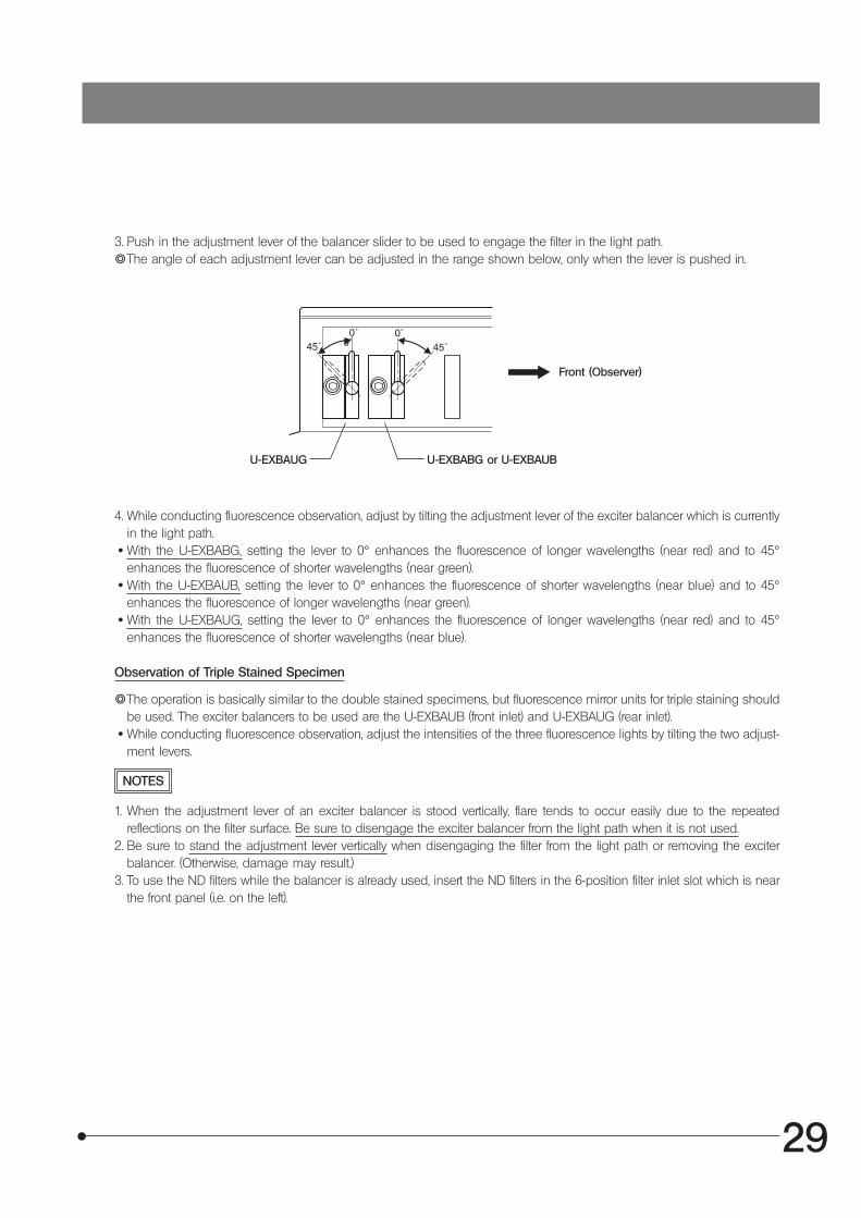
0˚
3. Push in the adjustment lever of the balancer slider to be used to engage the filter in the light path.}The angle of each adjustment lever can be adjusted in the range shown below, only when the lever is pushed in.
4. While conducting fluorescence observation, adjust by tilting the adjustment lever of the exciter balancer which is currentlyin the light path.
· With the U-EXBABG, setting the lever to 0° enhances the fluorescence of longer wavelengths (near red) and to 45°enhances the fluorescence of shorter wavelengths (near green).
· With the U-EXBAUB, setting the lever to 0° enhances the fluorescence of shorter wavelengths (near blue) and to 45°enhances the fluorescence of longer wavelengths (near green).
· With the U-EXBAUG, setting the lever to 0° enhances the fluorescence of longer wavelengths (near red) and to 45°enhances the fluorescence of shorter wavelengths (near blue).
Front (Observer)
Observation of Triple Stained Specimen
}The operation is basically similar to the double stained specimens, but fluorescence mirror units for triple staining shouldbe used. The exciter balancers to be used are the U-EXBAUB (front inlet) and U-EXBAUG (rear inlet).
· While conducting fluorescence observation, adjust the intensities of the three fluorescence lights by tilting the two adjust-ment levers.
NOTES
1. When the adjustment lever of an exciter balancer is stood vertically, flare tends to occur easily due to the repeatedreflections on the filter surface. Be sure to disengage the exciter balancer from the light path when it is not used.
2. Be sure to stand the adjustment lever vertically when disengaging the filter from the light path or removing the exciterbalancer. (Otherwise, damage may result.)
3. To use the ND filters while the balancer is already used, insert the ND filters in the 6-position filter inlet slot which is nearthe front panel (i.e. on the left).
U-EXBAUG U-EXBABG or U-EXBAUB
30
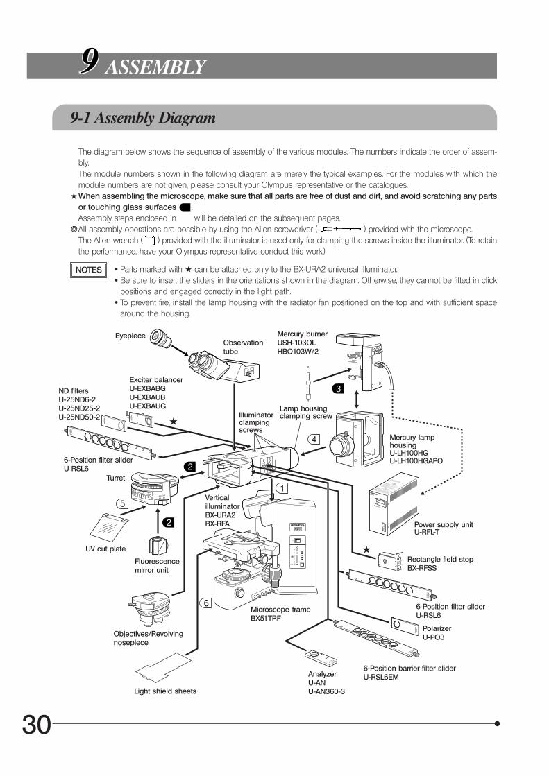
The diagram below shows the sequence of assembly of the various modules. The numbers indicate the order of assem-bly.The module numbers shown in the following diagram are merely the typical examples. For the modules with which themodule numbers are not given, please consult your Olympus representative or the catalogues.
#When assembling the microscope, make sure that all parts are free of dust and dirt, and avoid scratching any partsor touching glass surfaces .Assembly steps enclosed in will be detailed on the subsequent pages.
}All assembly operations are possible by using the Allen screwdriver ( ) provided with the microscope.The Allen wrench ( ) provided with the illuminator is used only for clamping the screws inside the illuminator. (To retainthe performance, have your Olympus representative conduct this work.)
ASSEMBLY
9-1 Assembly Diagram
NOTES · Parts marked with # can be attached only to the BX-URA2 universal illuminator. · Be sure to insert the sliders in the orientations shown in the diagram. Otherwise, they cannot be fitted in click
positions and engaged correctly in the light path. · To prevent fire, install the lamp housing with the radiator fan positioned on the top and with sufficient space
around the housing.
EyepieceObservationtube
Exciter balancerU-EXBABGU-EXBAUBU-EXBAUG
ND filtersU-25ND6-2U-25ND25-2U-25ND50-2
VerticalilluminatorBX-URA2BX-RFA
Turret
UV cut plate
Fluorescencemirror unit
Objectives/Revolvingnosepiece
Light shield sheets
Mercury burnerUSH-103OLHBO103W/2
Mercury lamphousingU-LH100HGU-LH100HGAPO
Lamp housingclamping screwIlluminator
clampingscrews
Power supply unitU-RFL-T
Rectangle field stopBX-RFSS
PolarizerU-PO3
6-Position barrier filter sliderU-RSL6EMAnalyzer
U-ANU-AN360-3
Microscope frameBX51TRF
6-Position filter sliderU-RSL6
6-Position filter sliderU-RSL6
31
9-2 Detailed Assembly Procedures
Fig. 10
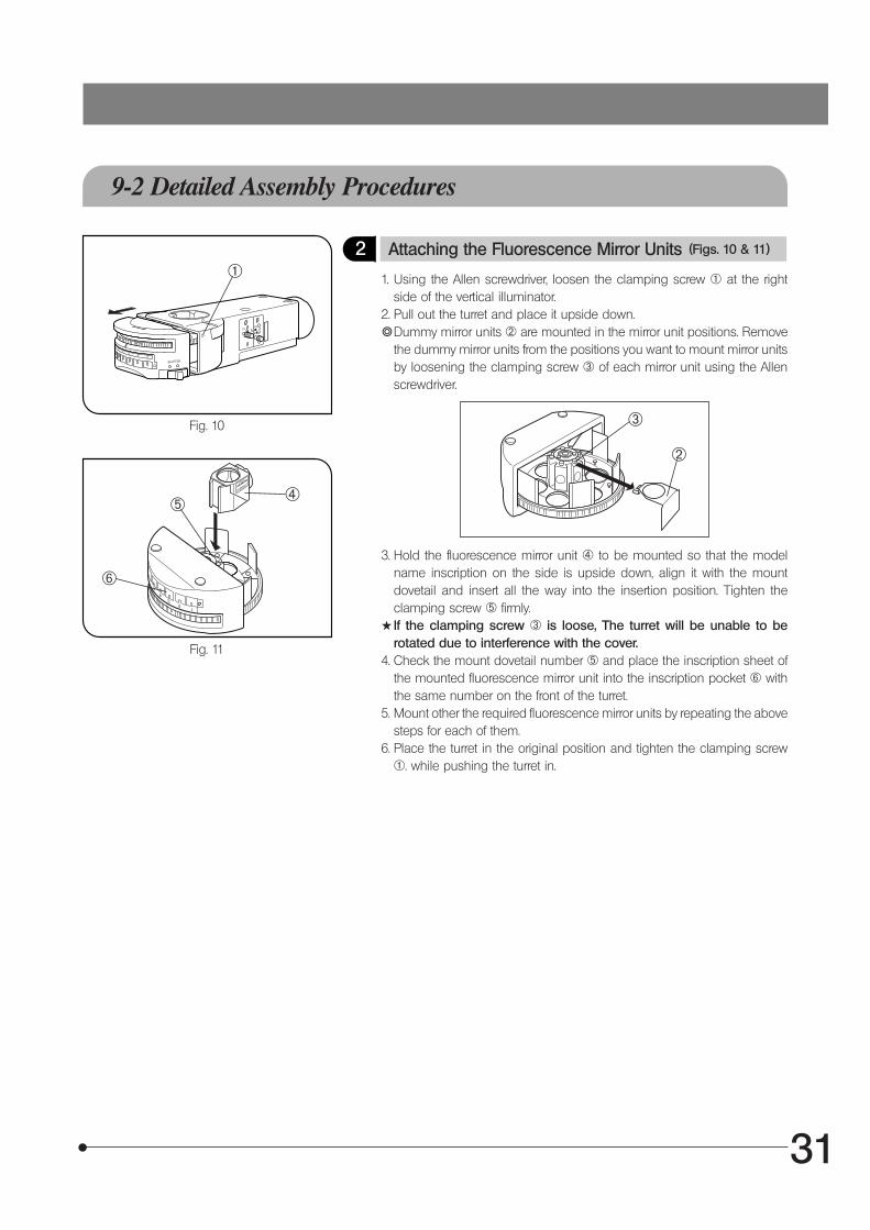
2 Attaching the Fluorescence Mirror Units (Figs. 10 & 11)
1. Using the Allen screwdriver, loosen the clamping screw @ at the rightside of the vertical illuminator.
2. Pull out the turret and place it upside down.}Dummy mirror units ² are mounted in the mirror unit positions. Remove
the dummy mirror units from the positions you want to mount mirror unitsby loosening the clamping screw ³ of each mirror unit using the Allenscrewdriver.
3. Hold the fluorescence mirror unit | to be mounted so that the modelname inscription on the side is upside down, align it with the mountdovetail and insert all the way into the insertion position. Tighten theclamping screw ƒ firmly.
#If the clamping screw ³ is loose, The turret will be unable to berotated due to interference with the cover.
4. Check the mount dovetail number ƒ and place the inscription sheet ofthe mounted fluorescence mirror unit into the inscription pocket … withthe same number on the front of the turret.
5. Mount other the required fluorescence mirror units by repeating the abovesteps for each of them.
6. Place the turret in the original position and tighten the clamping screw@. while pushing the turret in.
Fig. 11
@
²
³
|ƒ
…
32
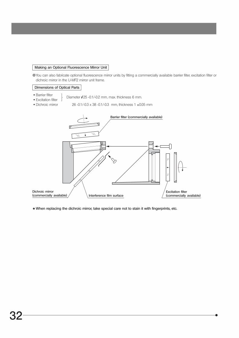
Making an Optional Fluorescence Mirror Unit
}You can also fabricate optional fluorescence mirror units by fitting a commercially available barrier filter, excitation filter ordichroic mirror in the U-MF2 mirror unit frame.
Dimensions of Optical Parts
· Barrier filter · Excitation filter · Dichroic mirror 26 -0.1/-0.3 x 38 -0.1/-0.3 mm, thickness 1 ±0.05 mm
#When replacing the dichroic mirror, take special care not to stain it with fingerprints, etc.
Diameter 25 -0.1/-0.2 mm, max. thickness 6 mm.
Barrier filter (commercially available)
Dichroic mirror(commercially available) Interference film surface
Excitation filter(commercially available)
33
Fig. 12
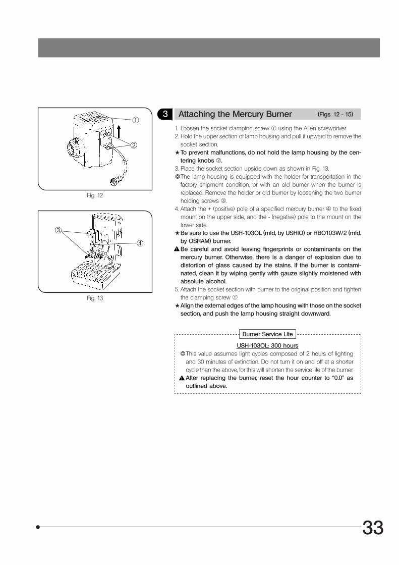
3 Attaching the Mercury Burner (Figs. 12 - 15)
1. Loosen the socket clamping screw @ using the Allen screwdriver.2. Hold the upper section of lamp housing and pull it upward to remove the
socket section.#To prevent malfunctions, do not hold the lamp housing by the cen-
tering knobs ².3. Place the socket section upside down as shown in Fig. 13.}The lamp housing is equipped with the holder for transportation in the
factory shipment condition, or with an old burner when the burner isreplaced. Remove the holder or old burner by loosening the two burnerholding screws ³.
4. Attach the + (positive) pole of a specified mercury burner | to the fixedmount on the upper side, and the - (negative) pole to the mount on thelower side.
#Be sure to use the USH-103OL (mfd, by USHIO) or HBO103W/2 (mfd.by OSRAM) burner.Be careful and avoid leaving fingerprints or contaminants on themercury burner. Otherwise, there is a danger of explosion due todistortion of glass caused by the stains. If the burner is contami-nated, clean it by wiping gently with gauze slightly moistened withabsolute alcohol.
5. Attach the socket section with burner to the original position and tightenthe clamping screw @.
#Align the external edges of the lamp housing with those on the socketsection, and push the lamp housing straight downward.
Fig. 13
@
²
³
|
Burner Service Life
USH-103OL: 300 hours}This value assumes light cycles composed of 2 hours of lighting
and 30 minutes of extinction. Do not turn it on and off at a shortercycle than the above, for this will shorten the service life of the burner.After replacing the burner, reset the hour counter to “0.0” asoutlined above.
34
II. REFLECTED OBSERVATIONS (BX-URA2 Only)
CONFIGURATION OF REFLECTED OBSERVATION SYSTEM
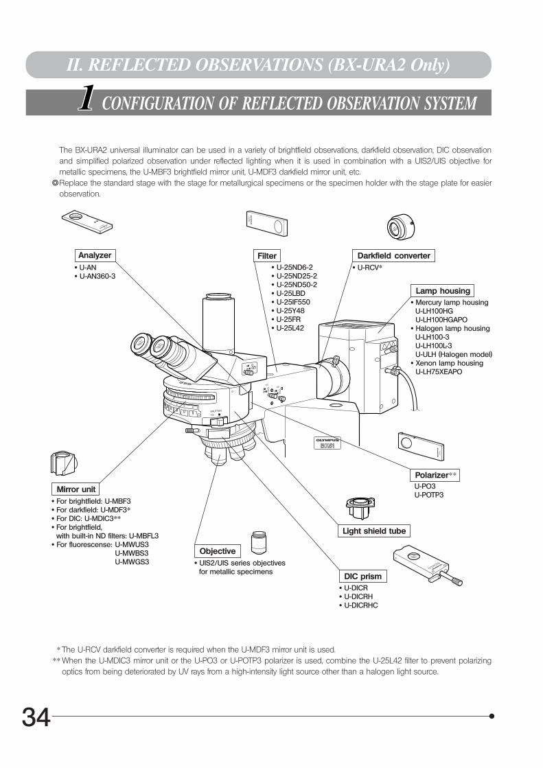
The BX-URA2 universal illuminator can be used in a variety of brightfield observations, darkfield observation, DIC observationand simplified polarized observation under reflected lighting when it is used in combination with a UIS2/UIS objective formetallic specimens, the U-MBF3 brightfield mirror unit, U-MDF3 darkfield mirror unit, etc.
}Replace the standard stage with the stage for metallurgical specimens or the specimen holder with the stage plate for easierobservation.
Analyzer Filter Darkfield converter
Lamp housing
Polarizer**
Mirror unit
Objective
Light shield tube
DIC prism
· U-AN· U-AN360-3
· U-25ND6-2· U-25ND25-2· U-25ND50-2· U-25LBD· U-25IF550· U-25Y48· U-25FR· U-25L42
· U-RCV*
· Mercury lamp housing U-LH100HG U-LH100HGAPO· Halogen lamp housing U-LH100-3 U-LH100L-3 U-ULH (Halogen model)· Xenon lamp housing U-LH75XEAPO
· For brightfield: U-MBF3· For darkfield: U-MDF3*· For DIC: U-MDIC3**· For brightfield, with built-in ND filters: U-MBFL3· For fluorescense: U-MWUS3
U-MWBS3U-MWGS3
U-PO3 U-POTP3
· UIS2/UIS series objectives for metallic specimens
· U-DICR· U-DICRH· U-DICRHC
* The U-RCV darkfield converter is required when the U-MDF3 mirror unit is used.** When the U-MDIC3 mirror unit or the U-PO3 or U-POTP3 polarizer is used, combine the U-25L42 filter to prevent polarizing
optics from being deteriorated by UV rays from a high-intensity light source other than a halogen light source.
35
ASSEMBLY
}This chapter pertains only to the assembly of items which cannot be assembled in the same way as the fluorescencemodules.
Fig. 14
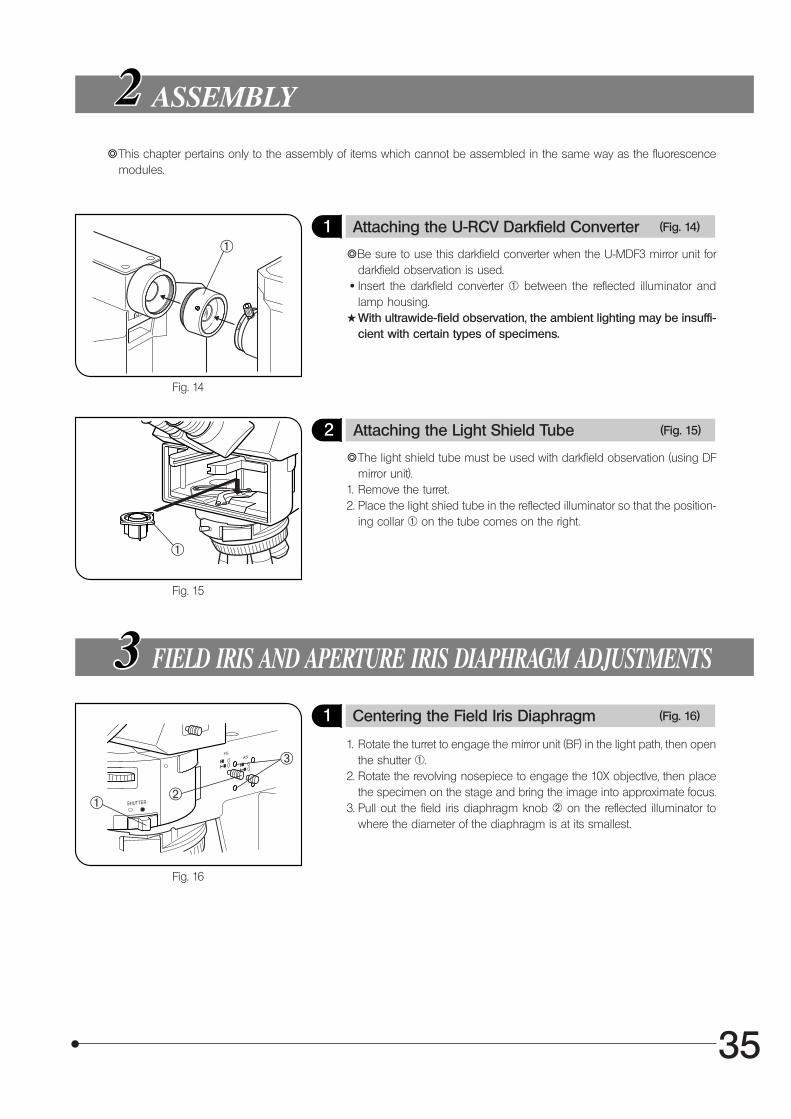
1 Attaching the U-RCV Darkfield Converter (Fig. 14)
}Be sure to use this darkfield converter when the U-MDF3 mirror unit fordarkfield observation is used.
· Insert the darkfield converter @ between the reflected illuminator andlamp housing.
#With ultrawide-field observation, the ambient lighting may be insuffi-cient with certain types of specimens.
Fig. 15
2 Attaching the Light Shield Tube (Fig. 15)
}The light shield tube must be used with darkfield observation (using DFmirror unit).
1. Remove the turret.2. Place the light shied tube in the reflected illuminator so that the position-
ing collar @ on the tube comes on the right.
FIELD IRIS AND APERTURE IRIS DIAPHRAGM ADJUSTMENTS
1. Rotate the turret to engage the mirror unit (BF) in the light path, then openthe shutter @.
2. Rotate the revolving nosepiece to engage the 10X objectlve, then placethe specimen on the stage and bring the image into approximate focus.
3. Pull out the field iris diaphragm knob ² on the reflected illuminator towhere the diameter of the diaphragm is at its smallest.
Fig. 16
1 Centering the Field Iris Diaphragm (Fig. 16)
@
@
@ ²
³
36
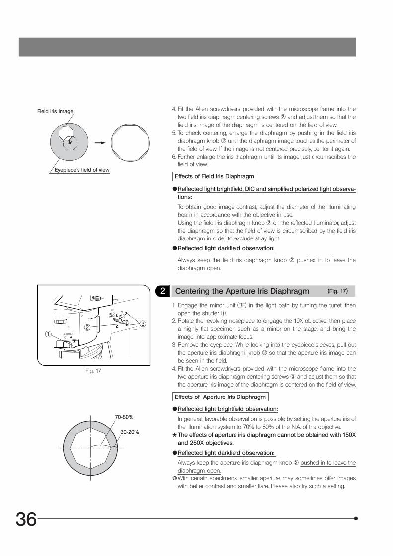
4. Fit the Allen screwdrivers provided with the microscope frame into thetwo field iris diaphragm centering screws ³ and adjust them so that thefield iris image of the diaphragm is centered on the field of view.
5. To check centering, enlarge the diaphragm by pushing in the field irisdiaphragm knob ² until the diaphragm image touches the perimeter ofthe field of view. If the image is not centered precisely, center it again.
6. Further enlarge the iris diaphragm until its image just circumscribes thefield of view.
Fig. 17
Effects of Field Iris Diaphragm
{Reflected light brightfield, DIC and simplified polarized light observa-tions:
To obtain good image contrast, adjust the diameter of the illuminatingbeam in accordance with the objective in use.Using the field iris diaphragm knob ² on the reflected illuminator, adjustthe diaphragm so that the field of view is circumscribed by the field irisdiaphragm in order to exclude stray light.
{Reflected light darkfield observation:
Always keep the field iris diaphragm knob ² pushed in to leave thediaphragm open.
2 Centering the Aperture Iris Diaphragm (Fig. 17)
1. Engage the mirror unit (BF) in the light path by turning the turret, thenopen the shutter @.
2. Rotate the revolving nosepiece to engage the 10X objective, then placea highly flat specimen such as a mirror on the stage, and bring theimage into approximate focus.
3 Remove the eyepiece. While looking into the eyepiece sleeves, pull outthe aperture iris diaphragm knob ² so that the aperture iris image canbe seen in the field.
4. Fit the Allen screwdrivers provided with the microscope frame into thetwo aperture iris diaphragm centering screws ³ and adjust them so thatthe aperture iris image of the diaphragm is centered on the field of view.
Effects of Aperture Iris Diaphragm
{Reflected light brightfield observation:
In general, favorable observation is possible by setting the aperture iris ofthe illumination system to 70% to 80% of the N.A. of the objective.
#The effects of aperture iris diaphragm cannot be obtained with 150Xand 250X objectives.
{Reflected light darkfield observation:
Always keep the aperture iris diaphragm knob ² pushed in to leave thediaphragm open.
}With certain specimens, smaller aperture may sometimes offer imageswith better contrast and smaller flare. Please also try such a setting.
@² ³
70-80%
30-20%
Field iris image
Eyepiece’s field of view
37
OBSERVATIONS
4-1 Reflected Light Brightfield/Darkfield Observations
Fig. 18
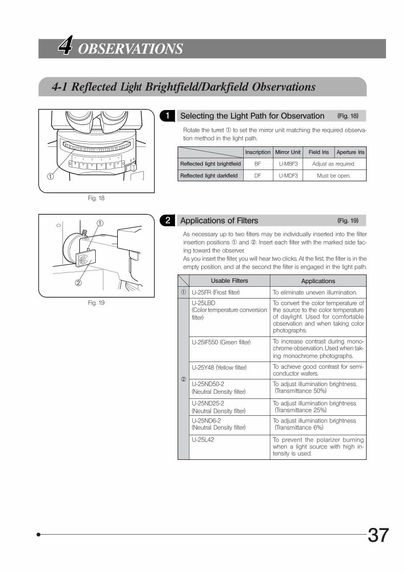
1 Selecting the Light Path for Observation (Fig. 18)
Rotate the turret @ to set the mirror unit matching the required observa-tion method in the light path.
Inscription
Fig. 19
2 Applications of Filters (Fig. 19)
As necessary up to two filters may be individually inserted into the filterinsertion positions @ and ². Insert each filter with the marked side fac-ing toward the observer.As you insert the filter, you will hear two clicks. At the first, the filter is in theempty position, and at the second the filter is engaged in the light path.
Usable Filters
Mirror Unit Field Iris Aperture Iris
Reflected light brightfield BF U-MBF3 Adjust as required.
Reflected light darkfield DF U-MDF3 Must be open.
Applications
U-25FR (Frost filter) To eliminate uneven illumination.
U-25LBD(Color temperature conversionfilter)
To convert the color temperature ofthe source to the color temperatureof daylight. Used for comfortableobservation and when taking colorphotographs.
U-25IF550 (Green filter) To increase contrast during mono-chrome observation. Used when tak-ing monochrome photographs.
U-25ND25-2(Neutral Density filter)
To adjust illumination brightness. (Transmittance 25%)
U-25ND6-2(Neutral Density filter)
To adjust illumination brightness (Transmittance 6%)
@
²
@
²
@
U-25L42 To prevent the polarizer burningwhen a light source with high in-tensity is used.
U-25Y48 (Yellow filter) To achieve good contrast for semi-conductor wafers.
U-25ND50-2(Neutral Density filter)
To adjust illumination brightness. (Transmittance 50%)
38
Reflected Light Nomarski Differential Interference Contrast (DIC) Observation4-2
#The performance of polarizer may deteriorate when it has been exposed to light for a long period (about con-tinuous 2000 hours). If this happens, replace the polarizer.
#When using the high-intensity light source, be sure to use the U-25L42 filter for prevention of the polarizer burn.}When performing sensitive color observation using the U-DICRH DIC slider, combine the U-POTP3 polarizer.
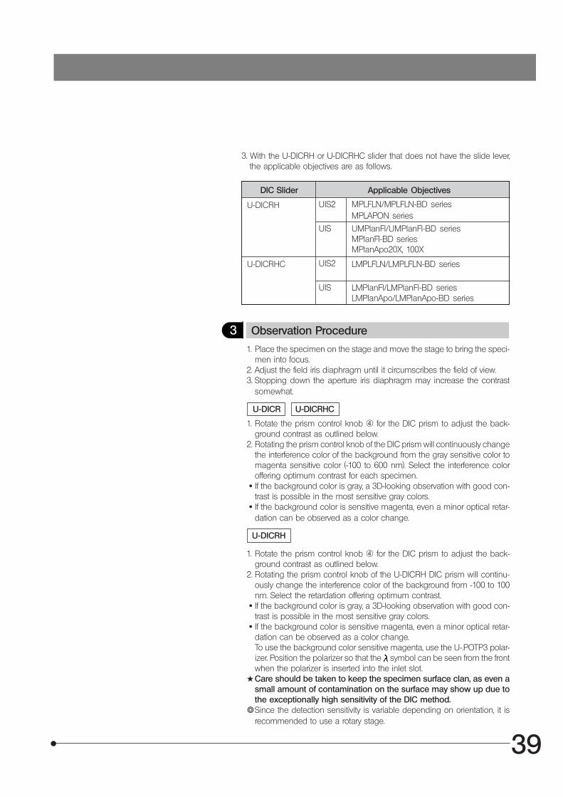
1. Loosen the DIC clamping knob @ at the front of the DIC revolving nose-piece, and insert the DIC prism ² with the inscription facing upward.
2. With the U-DICR interference slider, set the slide lever ³ according to theobjective in use.
Fig. 20
1 Selecting the Light Path for Observation (Fig. 20)
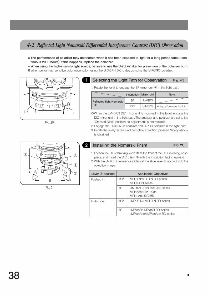
1. Rotate the turret to engage the BF mirror unit @ in the light path.
}When the U-MDIC3 DIC mirror unit is mounted in the turret, engage theDIC mirror unit in the light path. The analyzer and polarizer are set to the“Crossed Nicol” position so adjustment is not required.
2. Engage the U-AN360-3 analyzer and U-PO3 polarizer in the light path.3 Rotate the analyzer dial until complete extinction (crossed Nicol position)
is obtained.
Inscription Mirror Unit Note
Reflected light NomarskiDIC
BF U-MBF3
DIC U-MDIC3 Analyzer/polarizer built in
@
Fig. 21
2 Installing the Nomarski Prism (Fig. 21)
@ ²
³
|
Lever ³ position Applicable Objectives
Pushed in UIS2 MPLFLN/MPLFLN-BD seriesMPLAPON series
UIS UMPlanFl/UMPlanFl-BD seriesMPlanApo20X, 100XMPlanApo100XBD
Pulled out UIS2 LMPLFLN/LMPLFLN-BD series
UIS LMPlanFl/LMPlanFl-BD seriesLMPlanApo/LMPlanApo-BD series
39
3. With the U-DICRH or U-DICRHC slider that does not have the slide lever,the applicable objectives are as follows.
DIC Slider Applicable Objectives
U-DICRH MPLFLN/MPLFLN-BD seriesMPLAPON series
UMPlanFl/UMPlanFl-BD seriesMPlanFl-BD seriesMPlanApo20X, 100X
U-DICRHC LMPLFLN/LMPLFLN-BD series
LMPlanFl/LMPlanFl-BD seriesLMPlanApo/LMPlanApo-BD series
UIS2
UIS
UIS2
UIS
3 Observation Procedure
1. Place the specimen on the stage and move the stage to bring the speci-men into focus.
2. Adjust the field iris diaphragm until it circumscribes the field of view.3. Stopping down the aperture iris diaphragm may increase the contrast
somewhat.
1. Rotate the prism control knob | for the DIC prism to adjust the back-ground contrast as outlined below.
2. Rotating the prism control knob of the DIC prism will continuously changethe interference color of the background from the gray sensitive color tomagenta sensitive color (-100 to 600 nm). Select the interference coloroffering optimum contrast for each specimen.
· If the background color is gray, a 3D-looking observation with good con-trast is possible in the most sensitive gray colors.
· If the background color is sensitive magenta, even a minor optical retar-dation can be observed as a color change.
1. Rotate the prism control knob | for the DIC prism to adjust the back-ground contrast as outlined below.
2. Rotating the prism control knob of the U-DICRH DIC prism will continu-ously change the interference color of the background from -100 to 100nm. Select the retardation offering optimum contrast.
· If the background color is gray, a 3D-looking observation with good con-trast is possible in the most sensitive gray colors.
· If the background color is sensitive magenta, even a minor optical retar-dation can be observed as a color change.To use the background color sensitive magenta, use the U-.POTP3 polar-izer. Position the polarizer so that the symbol can be seen from the frontwhen the polarizer is inserted into the inlet slot.
#Care should be taken to keep the specimen surface clan, as even asmall amount of contamination on the surface may show up due tothe exceptionally high sensitivity of the DIC method.
}Since the detection sensitivity is variable depending on orientation, it isrecommended to use a rotary stage.
U-DICRHCU-DICR
U-DICRH
40
1. Loosen the DIC clamping screw @ at the front of the revolving nose-piece, and gently pull the DIC prism ² outward until a click is heard.Tighten the claming screw again.
2. Rotate the turret to disengage the U-MDIC3 DIC mirror unit from the lightpath.Or slide the analyzer/polarizer to disengage it from the light path.
Switching Between Brightfield andDarkfield Observation
4-3 Reflected Light Simple Polarized Light Observation
}To prepare for simple polarized light observation using the reflected illuminator, perform the operations in paragraph “Selecting the Light Path” in section 4-2, “Reflected Light Nomarski DIC Observation” on page 38.
1 Observation Procedure
1. Place the specimen on the stage and move the stage to bring the specimen into focus. Simple polarized light observa-tion is now possible.
2. Adjust the field iris diaphragm until the diaphragm opening circumscribes the field of view.3. Stopping down the aperture iris diaphragm may increase the contrast somewhat.
1
4
41
5X 0.13 15.0 — 2.58 50X 70 4.4 50X 70 5.310X 0.25 10.0 — 1.34 100X 18 2.2 100X 18 2.6520X 0.40 12.0 0 0.84 200X 6.1 1.1 200X 6.1 1.3350X 0.50 10.6 0 0.67 500X 2.5 0.44 500X 2.5 0.53
100X 0.80 3.3 0 0.42 1000X 0.87 0.22 1000X 0.87 0.27
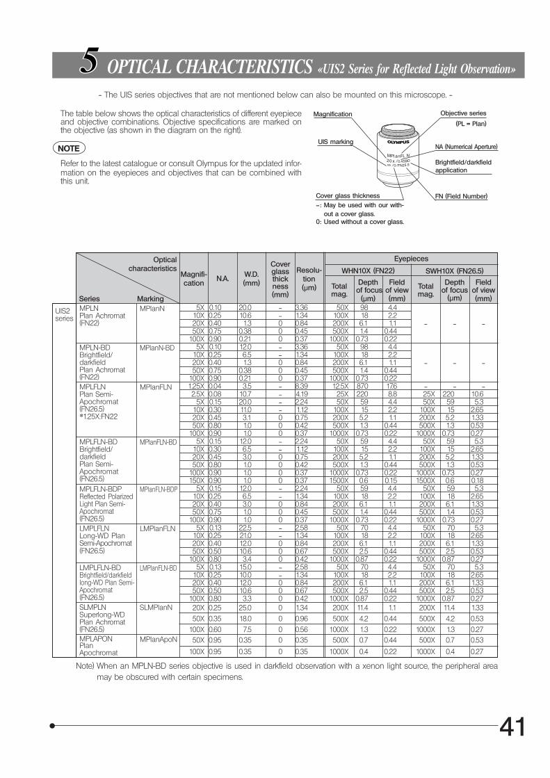
OPTICAL CHARACTERISTICS «UIS2 Series for Reflected Light Observation»
The table below shows the optical characteristics of different eyepieceand objective combinations. Objective specifications are marked onthe objective (as shown in the diagram on the right).
NOTE
Refer to the latest catalogue or consult Olympus for the updated infor-mation on the eyepieces and objectives that can be combined withthis unit.
Magnification
UIS marking
Cover glass thickness—: May be used with our with-
out a cover glass.0: Used without a cover glass.
-- The UIS series objectives that are not mentioned below can also be mounted on this microscope. --
FN (Field Number)
Objective series
(PL = Plan)
NA (Numerical Aperture)
Brightfield/darkfieldapplication
Opticalcharacteristics
Magnifi-cation
N.A. W.D.(mm)
Coverglassthickness(mm)
Resolu-tion(μm)
Eyepieces
Series
WHN10X (FN22) SWH10X (FN26.5)
Totalmag.
Depth of focus
(μm)
Fieldof view(mm)
Totalmag.
Depthof focus
(μm)
Fieldof view(mm)
MPLNPlan Achromat(FN22)
MPLN-BDBrightfield/darkfieldPlan Achromat(FN22)
5X 0.10 20.0 — 3.36 50X 98 4.410X 0.25 10.6 — 1.34 100X 18 2.220X 0.40 1.3 0 0.84 200X 6.1 1.1 — — —50X 0.75 0.38 0 0.45 500X 1.4 0.44
100X 0.90 0.21 0 0.37 1000X 0.73 0.225X 0.10 12.0 — 3.36 50X 98 4.4
10X 0.25 6.5 — 1.34 100X 18 2.220X 0.40 1.3 0 0.84 200X 6.1 1.1 — — —50X 0.75 0.38 0 0.45 500X 1.4 0.44
100X 0.90 0.21 0 0.37 1000X 0.73 0.22
MarkingMPlanN
MPlanN-BD
UIS2series
MPLFLNPlan Semi-Apochromat(FN26.5)*1.25X:FN22
MPlanFLN
MPLFLN-BDBrightfield/darkfieldPlan Semi-Apochromat(FN26.5)
MPlanFLN-BD
MPLFLN-BDPReflected PolarizedLight Plan Semi-Apochromat(FN26.5)
MPlanFLN-BDP
LMPLFLNLong-WD PlanSemi-Apochromat(FN26.5)
LMPlanFLN
LMPLFLN-BDBrightfield/darkfieldlong-WD Plan Semi-Apochromat(FN26.5)
LMPlanFLN-BD
1.25X 0.04 3.5 — 8.39 12.5X 870 17.6 — — —2.5X 0.08 10.7 — 4.19 25X 220 8.8 25X 220 10.6
5X 0.15 20.0 — 2.24 50X 59 4.4 50X 59 5.310X 0.30 11.0 — 1.12 100X 15 2.2 100X 15 2.6520X 0.45 3.1 0 0.75 200X 5.2 1.1 200X 5.2 1.3350X 0.80 1.0 0 0.42 500X 1.3 0.44 500X 1.3 0.53
100X 0.90 1.0 0 0.37 1000X 0.73 0.22 1000X 0.73 0.275X 0.15 12.0 — 2.24 50X 59 4.4 50X 59 5.3
10X 0.30 6.5 — 1.12 100X 15 2.2 100X 15 2.6520X 0.45 3.0 0 0.75 200X 5.2 1.1 200X 5.2 1.3350X 0.80 1.0 0 0.42 500X 1.3 0.44 500X 1.3 0.53
100X 0.90 1.0 0 0.37 1000X 0.73 0.22 1000X 0.73 0.27150X 0.90 1.0 0 0.37 1500X 0.6 0.15 1500X 0.6 0.18
5X 0.15 12.0 — 2.24 50X 59 4.4 50X 59 5.310X 0.25 6.5 — 1.34 100X 18 2.2 100X 18 2.6520X 0.40 3.0 0 0.84 200X 6.1 1.1 200X 6.1 1.3350X 0.75 1.0 0 0.45 500X 1.4 0.44 500X 1.4 0.53
100X 0.90 1.0 0 0.37 1000X 0.73 0.22 1000X 0.73 0.275X 0.13 22.5 — 2.58 50X 70 4.4 50X 70 5.3
10X 0.25 21.0 — 1.34 100X 18 2.2 100X 18 2.6520X 0.40 12.0 0 0.84 200X 6.1 1.1 200X 6.1 1.3350X 0.50 10.6 0 0.67 500X 2.5 0.44 500X 2.5 0.53
100X 0.80 3.4 0 0.42 1000X 0.87 0.22 1000X 0.87 0.27
Note) When an MPLN-BD series objective is used in darkfield observation with a xenon light source, the peripheral areamay be obscured with certain specimens.
SLMPLNSuperlong-WDPlan Achromat(FN26.5)
SLMPlanN 20X 0.25 25.0 0 1.34 200X 11.4 1.1 200X 11.4 1.33
50X 0.35 18.0 0 0.96 500X 4.2 0.44 500X 4.2 0.53
100X 0.60 7.5 0 0.56 1000X 1.3 0.22 1000X 1.3 0.27MPLAPONPlanApochromat
MPlanApoN 50X 0.95 0.35 0 0.35 500X 0.7 0.44 500X 0.7 0.53
100X 0.95 0.35 0 0.35 1000X 0.4 0.22 1000X 0.4 0.27
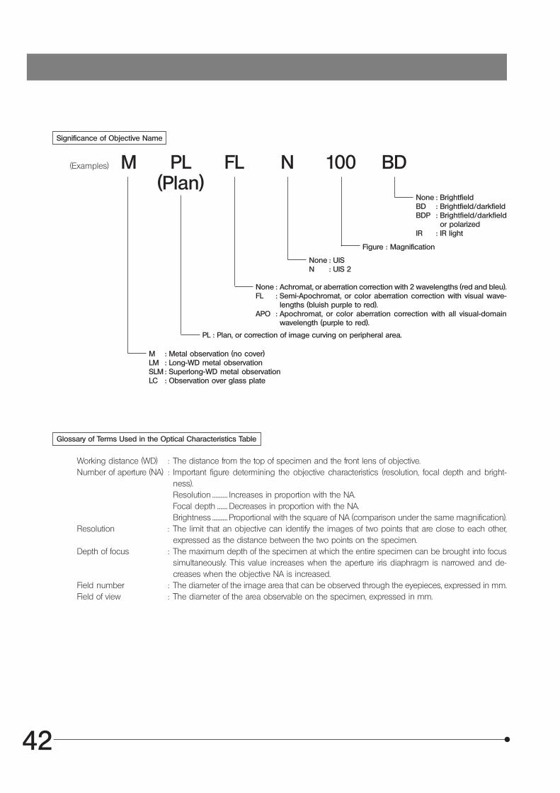
42
Significance of Objective Name
(Examples) M PL FL N 100 BD(Plan)
None : UISN : UIS 2
None : Achromat, or aberration correction with 2 wavelengths (red and bleu).FL : Semi-Apochromat, or color aberration correction with visual wave-
lengths (bluish purple to red).APO : Apochromat, or color aberration correction with all visual-domain
wavelength (purple to red).
PL : Plan, or correction of image curving on peripheral area.
M : Metal observation (no cover)LM : Long-WD metal observationSLM : Superlong-WD metal observationLC : Observation over glass plate
Glossary of Terms Used in the Optical Characteristics Table
Working distance (WD) : The distance from the top of specimen and the front lens of objective.Number of aperture (NA) : Important figure determining the objective characteristics (resolution, focal depth and bright-
ness).Resolution ............. Increases in proportion with the NA.Focal depth ......... Decreases in proportion with the NA.Brightness ............. Proportional with the square of NA (comparison under the same magnification).
Resolution : The limit that an objective can identify the images of two points that are close to each other,expressed as the distance between the two points on the specimen.
Depth of focus : The maximum depth of the specimen at which the entire specimen can be brought into focussimultaneously. This value increases when the aperture iris diaphragm is narrowed and de-creases when the objective NA is increased.
Field number : The diameter of the image area that can be observed through the eyepieces, expressed in mm.Field of view : The diameter of the area observable on the specimen, expressed in mm.
None : BrightfieldBD : Brightfield/darkfieldBDP : Brightfield/darkfield
or polarizedIR : IR light
Figure : Magnification
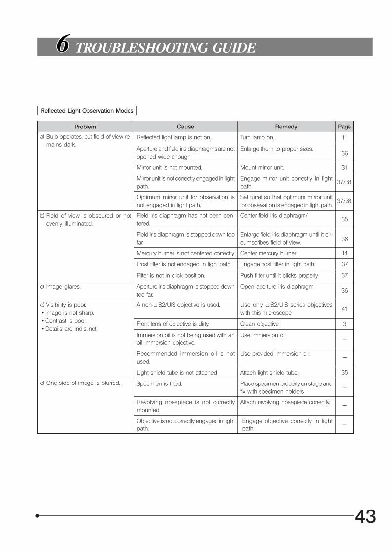
43
TROUBLESHOOTING GUIDE
Reflected Light Observation Modes
Problem Cause Remedy Page
11a) Bulb operates, but field of view re-mains dark.
Reflected light lamp is not on. Turn lamp on.
Aperture and field iris diaphragms are notopened wide enough.
Enlarge them to proper sizes.
Mirror unit is not mounted. Mount mirror unit.
Mirror unit is not correctly engaged in lightpath.
Engage mirror unit correctly in lightpath.
Optimum mirror unit for observation isnot engaged in light path.
Set turret so that optimum mirror unitfor observation is engaged in light path.
b) Field of view is obscured or notevenly illuminated.
Field iris diaphragm has not been cen-tered.
Center field iris diaphragm/
Field iris diaphragm is stopped down toofar.
Enlarge field iris diaphragm until it cir-cumscribes field of view.
Mercury burner is not centered correctly. Center mercury burner.
Frost filter is not engaged in light path. Engage frost filter in light path.
Filter is not in click position. Push filter until it clicks properly.
c) Image glares. Aperture iris diaphragm is stopped downtoo far.
Open aperture iris diaphragm.
d) Visibility is poor.· Image is not sharp.· Contrast is poor.· Details are indistinct.
A non-UIS2/UIS objective is used. Use only UIS2/UIS series objectiveswith this microscope.
Front lens of objective is dirty. Clean objective.
Immersion oil is not being used with anoil immersion objective.
Use immersion oil.
Recommended immersion oil is notused.
Use provided immersion oil.
Light shield tube is not attached. Attach light shield tube.
e) One side of image is blurred. Specimen is tilted. Place specimen properly on stage andfix with specimen holders.
Revolving nosepiece is not correctlymounted.
Attach revolving nosepiece correctly.
Objective is not correctly engaged in lightpath.
Engage objective correctly in lightpath.
36
31
37/38
37/38
35
36
14
37
37
36
41
3
––
––
35
––
––
––
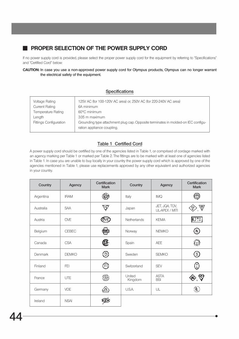
44
Table 1 Certified Cord
A power supply cord should be certified by one of the agencies listed in Table 1, or comprised of cordage marked with an agency marking per Table 1 or marked per Table 2. The fittings are to be marked with at least one of agencies listed in Table 1. In case you are unable to buy locally in your country the power supply cord which is approved by one of the agencies mentioned in Table 1, please use replacements approved by any other equivalent and authorized agencies in your country.
PROPER SELECTION OF THE POWER SUPPLY CORD
If no power supply cord is provided, please select the proper power supply cord for the equipment by referring to “Specifications” and “Certified Cord” below:
CAUTION: In case you use a non-approved power supply cord for Olympus products, Olympus can no longer warrant the electrical safety of the equipment.
Specifications
Voltage RatingCurrent RatingTemperature RatingLengthFittings Configuration
125V AC (for 100-120V AC area) or, 250V AC (for 220-240V AC area)6A minimum60°C minimum3.05 m maximumGrounding type attachment plug cap. Opposite terminates in molded-on IEC configu-ration appliance coupling.
Country Agency CertificationMark Country Agency Certification
Mark
Argentina IRAM Italy IMQ
Australia SAA JapanJET, JQA, TÜV,UL-APEX / MITI
Austria ÖVE Netherlands KEMA
Belgium CEBEC Norway NEMKO
Canada CSA Spain AEE
Denmark DEMKO Sweden SEMKO
Finland FEI Switzerland SEV
France UTE United Kingdom
ASTABSI
Germany VDE U.S.A. UL
Ireland NSAI
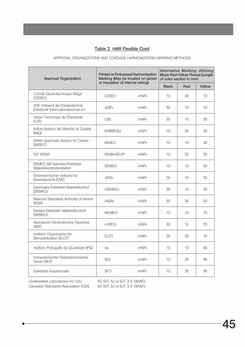
45
Table 2 HAR Flexible Cord
APPROVAL ORGANIZATIONS AND CORDAGE HARMONIZATION MARKING METHODS
Approval OrganizationPrinted or Embossed Harmonization Marking (May be located on jacket or insulation of internal wiring)
Alternative Marking Utilizing Black-Red-Yellow Thread (Length of color section in mm)
Black Red Yellow
Comité Électrotechnique Belge(CEBEC) CEBEC <HAR> 10 30 10
VDE Verband der Elektrotechnik Elektronik Informationstechnik e.V. <VDE> <HAR> 30 10 10
Union Technique de l’Électricité(UTE) USE <HAR> 30 10 30
Istituto Italiano del Marchio di Qualità (IMQ) IEMMEQU <HAR> 10 30 50
British Approvals Service for Cables (BASEC) BASEC <HAR> 10 10 30
N.V. KEMA KEMA-KEUR <HAR> 10 30 30
SEMKO AB Svenska Elektriska Materielkontrollanstalten SEMKO <HAR> 10 10 50
Österreichischer Verband für Elektrotechnik (ÖVE) <ÖVE> <HAR> 30 10 50
Danmarks Elektriske Materielkontrol(DEMKO) <DEMKO> <HAR> 30 10 30
National Standards Authority of Ireland (NSAI) <NSAI> <HAR> 30 30 50
Norges Elektriske Materiellkontroll(NEMKO) NEMKO <HAR> 10 10 70
Asociación Electrotécnica Española (AEE) <UNED> <HAR> 30 10 70
Hellenic Organization for Standardization (ELOT) ELOT <HAR> 30 30 70
Instituto Português da Qualidade (IPQ) np <HAR> 10 10 90
Schweizerischer Elektrotechnischer Verein (SEV) SEV <HAR> 10 30 90
Elektriska Inspektoratet SETI <HAR> 10 30 90
Underwriters Laboratories Inc. (UL) SV, SVT, SJ or SJT, 3 X 18AWGCanadian Standards Association (CSA) SV, SVT, SJ or SJT, 3 X 18AWG
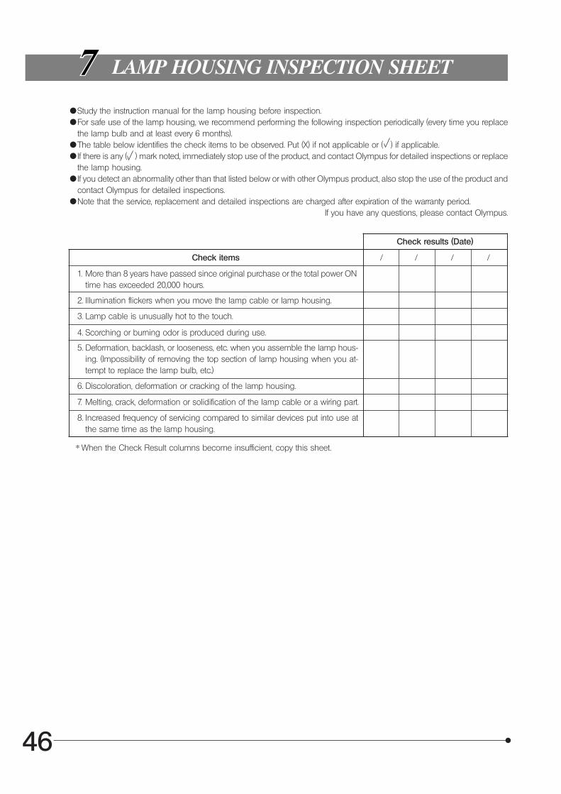
46
LAMP HOUSING INSPECTION SHEET
{Study the instruction manual for the lamp housing before inspection.{For safe use of the lamp housing, we recommend performing the following inspection periodically (every time you replace
the lamp bulb and at least every 6 months).{The table below identifies the check items to be observed. Put (X) if not applicable or ( ) if applicable.{If there is any ( ) mark noted, immediately stop use of the product, and contact Olympus for detailed inspections or replace
the lamp housing.{If you detect an abnormality other than that listed below or with other Olympus product, also stop the use of the product and
contact Olympus for detailed inspections.{Note that the service, replacement and detailed inspections are charged after expiration of the warranty period.
If you have any questions, please contact Olympus.
Check results (Date)
Check items / / / /
1. More than 8 years have passed since original purchase or the total power ONtime has exceeded 20,000 hours.
2. Illumination flickers when you move the lamp cable or lamp housing.
3. Lamp cable is unusually hot to the touch.
4. Scorching or burning odor is produced during use.
5. Deformation, backlash, or looseness, etc. when you assemble the lamp hous-ing. (Impossibility of removing the top section of lamp housing when you at-tempt to replace the lamp bulb, etc.)
6. Discoloration, deformation or cracking of the lamp housing.
7. Melting, crack, deformation or solidification of the lamp cable or a wiring part.
8. Increased frequency of servicing compared to similar devices put into use atthe same time as the lamp housing.
* When the Check Result columns become insufficient, copy this sheet.


Shinjuku Monolith, 3-1, Nishi Shinjuku 2-chome, Shinjuku-ku, Tokyo, Japan
Wendenstraße 14-18, 20097 Hamburg, Germany
3500 Corporate Parkway, P.O. Box 610, Center Valley, PA 18034-0610, U.S.A.
One Corporate Drive, Orangeburg, NY 10962, U.S.A.
491B River Valley Road, #12-01/04 Valley Point Office Tower, Singapore 248373
31 Gilby Road, Mount Waverley, VIC., 3149, Australia
5301 Blue Lagoon Drive, Suite 290 Miami, FL 33126, U.S.A.
EC REP
01/10
Related Documents