RFID Labeling Reference Manual Thermal RFID Printers

Welcome message from author
This document is posted to help you gain knowledge. Please leave a comment to let me know what you think about it! Share it to your friends and learn new things together.
Transcript

RFID Labeling Reference Manual
Thermal RFID Printers

Software License Agreement
CAREFULLY READ THE FOLLOWING TERMS AND CONDITIONS BEFORE USING THIS PRINTER. USING THIS PRINTER INDICATES YOUR ACCEPTANCE OF THESE TERMS AND CONDITIONS. IF YOU DO NOT AGREE TO THESE TERMS AND CONDITIONS, PROMPTLY RETURN THE PRINTER AND ALL ACCOMPANYING HARDWARE AND WRITTEN MATERIALS TO THE PLACE YOU OBTAINED THEM, AND YOUR MONEY WILL BE REFUNDED.
Definitions.
“Software” shall mean the digitally encoded, machine-readable data and program. The term “Software Product” includes the Software resident in the printer and its documentation. The Software Product is licensed (not sold) to you, and Printronix, Inc. either owns or licenses from other vendors who own, all copyright, trade secret, patent and other proprietary rights in the Software Product.
License.
1. Authorized Use. You agree to accept a non-exclusive license to use the Software resident in the printer solely for your own customary business or personal purposes.
2. Restrictions.
a. To protect the proprietary rights of Printronix Auto ID Technology, Inc., you agree to maintain the Software Product and other proprietary information concerning the typefaces in strict confidence.
b. You agree not to duplicate or copy the Software Product.
c. You shall not sublicense, sell, lease, or otherwise transfer all or any portion of the Software Product separate from the printer, without the prior written consent of Printronix Auto ID Technology, Inc.
d. You may not modify or prepare derivative works of the Software Product.
e. You may not transmit the Software Product over a network, by telephone, or electronically using any means; or reverse engineer, decompile or disassemble the Software.
f. You agree to keep confidential and use your best efforts to prevent and protect the contents of the Software Product from unauthorized disclosure or use.
3. Transfer. You may transfer the Software Product with the printer, but only if the recipient agrees to accept the terms and conditions of this Agreement. Your license is automatically terminated if you transfer the Software Product and printer.
Limited Software Product Warranty
Printronix Auto ID Technology, Inc. warrants that for ninety (90) days after delivery, the Software will perform in accordance with specifications published by Printronix Auto ID Technology, Inc. Printronix Auto ID Technology, Inc. does not warrant that the Software is free from all bugs, errors and omissions.

Remedy
Your exclusive remedy and the sole liability of Printronix Auto ID Technology, Inc. in connection with the Software is replacement of defective software with a copy of the same version and revision level.
Disclaimer of Warranties and Limitation of Remedies
1. THE PARTIES AGREE THAT ALL OTHER WARRANTIES, EXPRESS OR IMPLIED, INCLUDING WARRANTIES OF FITNESS FOR A PARTICULAR PURPOSE AND MERCHANTABILITY ARE EXCLUDED. Printronix Auto ID Technology, Inc. does not warrant that the functions contained in the Software will meet your requirements or that the operation of the Software will be uninterrupted or error free. Printronix, Inc. reserves the right to make changes and/or improvements in the Software without notice at any time.
2. IN NO EVENT WILL PRINTRONIX AUTO ID TECHNOLOGY, INC. BE LIABLE FOR LOST PROFITS, LOST DATA, BUSINESS INTERRUPTIONS, OR ANY OTHER DIRECT, INDIRECT, INCIDENTAL OR CONSEQUENTIAL DAMAGES ARISING OUT OF THE USE OF OR INABILITY TO USE THIS PRODUCT, EVEN IF PRINTRONIX, INC. HAS BEEN ADVISED OF THE POSSIBILITY OF SUCH DAMAGES, OR ANY DAMAGES CAUSED BY THE ABUSE OR MANIPULATION OF THE SOFTWARE. SOME STATES DO NOT ALLOW THE EXCLUSION OR LIMITATION OF LIABILITY FOR CONSEQUENTIAL OR INCIDENTAL DAMAGES, SO THE ABOVE LIMITATION MAY NOT APPLY TO YOU.
3. Printronix Auto ID Technology, Inc. will not be liable for any loss or damage caused by delay in furnishing a Software Product or any other performance under this Agreement.
4. Our entire liability and your exclusive remedies for our liability of any kind (including liability for negligence except liability for personal injury caused solely by our negligence) for the Software Product covered by this Agreement and all other performance or nonperformance by us under or related to this Agreement are limited to the remedies specified by this Agreement.
5. California law governs this Agreement.
Termination of License Agreement
This License shall continue until terminated. This license may be terminated by agreement between you and Printronix Auto ID Technology, Inc. or by Printronix Auto ID Technology, Inc. if you fail to comply with the terms of this License and such failure is not corrected within thirty (30) days after notice. When this License is terminated, you shall return to the place you obtained them, the printer and all copies of the Software and documentation.
U.S. Government Restricted Rights
Use, duplication or disclosure by the Government is subject to restrictions as set forth in the Rights in Technical Data and Computer Software clause at FAR 242.227-7013, subdivision (b) (3) (ii) or subparagraph (c) (1) (ii), as appropriate. Further use, duplication or disclosure is subject to restrictions applicable to restricted rights software as set forth in FAR 52.227-19 (c) (2).

Acknowledgement of Terms and Conditions
YOU ACKNOWLEDGE THAT YOU HAVE READ THIS AGREEMENT, UNDERSTAND IT, AND AGREE TO BE BOUND BY ITS TERMS AND CONDITIONS. NEITHER PARTY SHALL BE BOUND BY ANY STATEMENT OR REPRESENTATION NOT CONTAINED IN THIS AGREEMENT. NO CHANGE IN THIS AGREEMENT IS EFFECTIVE UNLESS WRITTEN AND SIGNED BY PROPERLY AUTHORIZED REPRESENTATIVES OF EACH PARTY. BY USING THIS PRINTER, YOU AGREE TO ACCEPT THE TERMS AND CONDITIONS OF THIS AGREEMENT.
COPYRIGHT © 2016 PRINTRONIX AUTO ID TECHNOLOGY, INC. All rights reserved.
Trademark Acknowledgements
Alien and Alien Technology are registered trademarks of Alien Technology Corporation.
Avery is a trademark of Avery Dennison Corporation.
Printronix, PGL, and PrintNet are registered trademarks of Printronix, Inc.
T6000, T8000, SL5000r, SL5R Energy Star, and SL4M are trademarks of Printronix, Inc.
Uniform Code Council, Inc. is a registered trademark of Uniform Code Council, Inc.
Zebra and ZPL are trademarks of Zebra Technologies Corporation.
Table of Contents
Software License Agreement .............................................................................. 2
Trademark Acknowledgements ........................................................................... 4
Reference Notes ............................................................ 8
Overview .............................................................................................................. 8
What to Expect when Running an RFID Application ........................................... 8
Factors Affecting Smart Label Performance ................................................. 8
Overstruck Smart Labels .............................................................................. 8
Smart Label Characteristics .......................................................................... 8
General Tag Type ......................................................................................... 8
Technology Tag Class .................................................................................... 8
Label Size ...................................................................................................... 9
Website Support ........................................................................................... 9
Smart Label Operation ................................................. 10
Overview ............................................................................................................ 10
Enable RFID ...................................................................................................... 10
Supported UHF Gen2 Tag Types ...................................................................... 11
Alien Tags ................................................................................................... 11
Avery Tags .................................................................................................. 12
Additional Tags ........................................................................................... 12
Higgs 3 EPC/USR Lengths and PC Values ................................................ 12
Overstrike Error Messages ................................................................................ 13
RFID Menu Overview ............................................................................. 14
Configuring the RFID ................................................................................ 15
Enabling and Disabling ............................................................................... 15
Checking Firmware Revision ...................................................................... 15
Reporting Statistics ..................................................................................... 16
Requesting an RFID/ODV Report ............................................................... 16
Resetting RFID Data ................................................................................... 16
Control Submenu ........................................................................................ 16
RFID Active ................................................................................................. 16
Tag Type ..................................................................................................... 17
Error Handling ............................................................................................. 17
Label Retry .................................................................................................. 17
Max Retry Error ........................................................................................... 18
Auto Retry ................................................................................................... 18
Overstrike Style ........................................................................................... 18
EPC Write Ctrl ............................................................................................. 18
Higgs 3 EPC Len ........................................................................................ 19

Auto Write PC ............................................................................................. 19
Tag Position ................................................................................................ 19
AutoID Mgr Rpt ........................................................................................... 20
Custom Tag Submenu ................................................................................ 20
Custom Active ............................................................................................. 20
Write Power................................................................................................. 20
Read Power ................................................................................................ 21
Min Power ................................................................................................... 21
Max Power .................................................................................................. 21
USR Size ..................................................................................................... 21
USR Address .............................................................................................. 22
TID Size ...................................................................................................... 22
TID Address ................................................................................................ 22
Block Size ................................................................................................... 22
Tag Class .................................................................................................... 23
Read Tries................................................................................................... 23
Write Tries ................................................................................................... 23
Start Position ............................................................................................... 23
Scan Length ................................................................................................ 24
Tag Length .................................................................................................. 24
EPC Address............................................................................................... 24
Diagnostics Submenu ................................................................................. 24
Read Tag .................................................................................................... 24
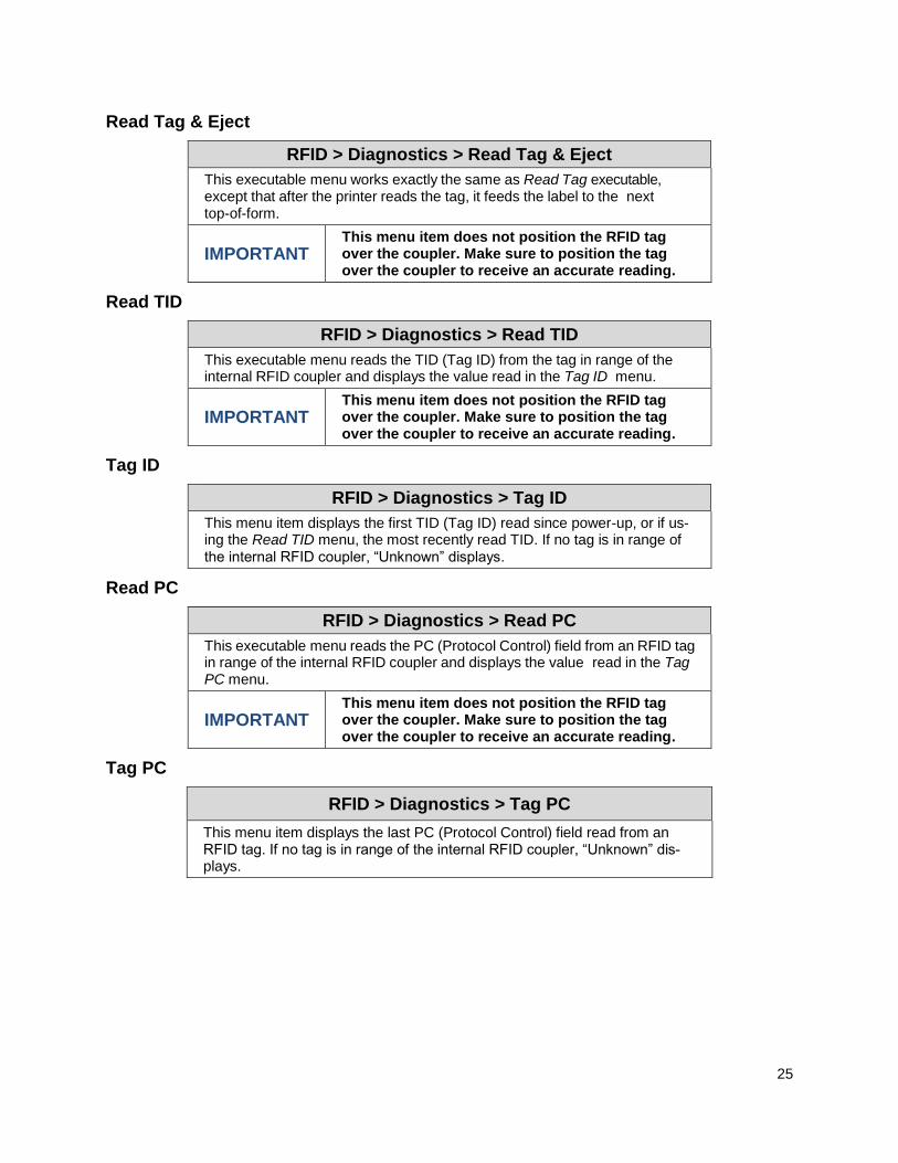
Read Tag & Eject ........................................................................................ 25
Read TID ..................................................................................................... 25
Tag ID ......................................................................................................... 25
Read PC ...................................................................................................... 25
Tag PC ........................................................................................................ 25
Write EPC with 1s ....................................................................................... 26
Write EPC with 2s ....................................................................................... 26
Statistics Submenu ..................................................................................... 26
Tag Write Count .......................................................................................... 26
Tag Failed Count ........................................................................................ 26
Tag Void Count ........................................................................................... 26
Tag Read Count .......................................................................................... 26
Clear Tag Stat ............................................................................................. 27
RFID Reader F/W ....................................................................................... 27
RFID Commands ......................................................... 28
PGL RFID Commands....................................................................................... 28
RFWTAG ..................................................................................................... 28
RFRTAG ..................................................................................................... 37
VERIFY ....................................................................................................... 39

ZGL RFID Commands ....................................................................................... 42
Read Tag ^RT ............................................................................................. 42
Write Tag ^WT ............................................................................................ 43
Write or Read Format ^RF .......................................................................... 43
Calibrate Transponder ^HR ........................................................................ 44
Define EPC Data Structure ^RB ................................................................. 44
Enable RFID Motion ^RM ........................................................................... 44
Specify RFID Retries for a Block ^RR ........................................................ 45
RFID Setup ^RS .......................................................................................... 45
Tag Password ^RZ ...................................................................................... 45
Host Verification ^HV .................................................................................. 46
EPC Programming Examples ..................................................................... 47
STGL RFID Commands .................................................................................... 49
RFID Write .................................................................................................. 49
RFID Write(IP0), RFID Read(IP1)............................................................... 50
PTX SETUP Commands ................................................................................... 50
RFID Antenna System ................................................. 52
Antenna System ................................................................................................ 52
Different Antenna Positions ........................................................................ 52
Selecting the Antenna Position ................................................................... 53
RFID Inlay Pitch ........................................................... 54
RFID Inlay Pitch ................................................................................................. 54
Short-Pitch RFID Labels .................................................................................... 55
On-Pitch RFID Labels........................................................................................ 56
Setting up the T6 RFID Printer .......................................................................... 57
Media > Media Handling ..................................................................... 57
Sensors > Control .............................................................................. 57
RFID > Control ................................................................................. 57
A Errors and Troubleshooting ........................................... 58
Error Messages ................................................................................................. 58
Troubleshooting ................................................................................................. 59
B Contact Information ....................................................... 61
Printronix Customer Support Center ................................................................. 61
Corporate Offices ........................................................................................ 62
8
Reference Notes
Overview
This manual covers the Printronix T6000 Multi-protocol RFID printer, Class Gen 2, RFID tags, and labels. For the latest version of this reference manual, visit the Services & Support page at www.PrintronixAutoID.com.
What to Expect when Running an RFID Application
Factors Affecting Smart Label Performance
Smart labels are based on an EEPROM technology that requires some time to be programmed. You may
notice this minor pause between labels. This time is necessary to better ensure consistent quality and
improved reliability.
When dealing with smart labels, it is possible that an occasional RFID tag may need to be written and
verified more than once (retry) before being considered acceptable. In this event each retry time will be
added to the inter-label pause.
Static electricity can damage the smart labels. Open the media cover of the printer and touch an unpainted metal part of the printer before you handle smart labels. This will discharge any static electricity that may have built up on your hands.
Overstruck Smart Labels
If an RFID tag within a smart label is deemed unacceptable after execution of the defined number of retries, what occurs next depends upon the RFID > Control > Error Handling setting. See section “Error Handling” on page 17.
Smart Label Characteristics
IMPORTANT: Purchase additional smart labels directly from Printronix Auto ID to assure the
highest level of performance and reliability. See the section “Printronix Customer
Support Center” on page 61.
Currently supported smart labels have the following characteristics:
General Tag Type
• UHF 869/915 MHz radio frequency
Technology Tag Class
EPC Class Gen 2 tags – 96 to 256 data bits EPC Read/Write, 512 bits User Memory.

9
Label Size
Refer to www.PrintronixAutoID.com/rfid-inlay-placement/ for the latest specifications.
Website Support
Printronix RFID printers support a number of RFID protocols and coupler configurations.
For a complete list of Certified RFID Smart Labels available from Printronix, go to
www.PrintronixAutoID.com/product/thermal-en/rfid-consumables/.
For a complete list of tag types supported by Printronix RFID printers, go to
www.PrintronixAutoID.com/rfid-inlay-placement/.
These web pages will be updated regularly to include newly supported RFID tag types and newly Certified
RFID Smart Labels available from Printronix.

10
Smart Label Operation
Overview
This chapter describes how to use the RFID encoder. The RFID encoder is designed to be transparent to the printer operation. It provides the capability of programming smart labels (with embedded RFID tags) while printing the label format. The smart labels are provided with the printer or purchased separately from Printronix.
There are several ways to program RFID tags in smart labels:
Incorporate RFID commands into new or existing Printronix PGL® programs. Command details start on page 28.
Incorporate RFID commands into new or existing ZPL™ programs. By selecting the Printronix ZGL emulation you can seamlessly upgrade from Zebra™ printers. Command details start on page 42.
Incorporate RFID commands into new or existing SATO® printer language programs. By selecting the Printronix STGL emulation you can seamlessly upgrade from SATO printers. Command details start on 49.
Enable RFID
IMPORTANT If you make any changes to the default configuration menu items, you will be
prompted to save the configuration when you attempt to put the printer online. See
the Adminstrator’s Manual for more information.
Software can automatically detect an installed RFID encoder when the printer is powered up. The state of the RFID feature can be observed from the ONLINE screen as shown in the Figure 1 below:
The ONLINE screen will show the “enabled” RFID symbol under the model number when the RFID encoder is installed AND enabled via the menu RFID > Control > RFID Active.
The ONLINE screen will show the “disabled” RFID symbol under the model number when the RFID encoder is installed and disabled via the menu RFID > Control > RFID Active.
If the RFID encoder is not installed, then no RFID symbol will be present on the ONLINE screen. Furthermore, the full color RFID icon shown in the Settings section in Figure 1 is replaced with a greyed out version which the user cannot select.

11
Figure 1 RFID Icon
Once the RFID is installed, the RFID section under Settings can be selected and the RFID configured. However, it may not be enabled by default:
If the printer is powered up with the menu Configs > Control > Power-Up Config set to Factory, the RFID > Control > Validator Active will be set to “Enable” automatically.
If the printer is powered up with Configs > Control > Power-Up Config to something other than Factory, the RFID > Control > Validator Active is set to “Disable”.
To enable the RFID feature, change the menu RFID > Control > RFID Active to “Enable” and save the configuration as described in the Administrator’s Manual.
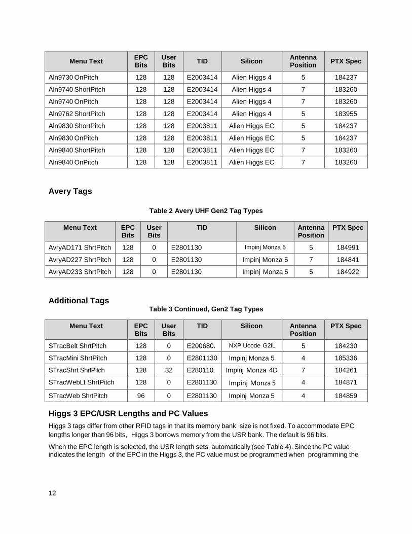
Supported UHF Gen2 Tag Types
Table 1 through Table 3 lists supported tag types in the order they appear in the menu (alphabetical order). Other types may be added in the future.
NOTE: For tag type specifications, go to www.PrintronixAutoID.com/rfid-inlay-placement/. Select
the desired Printronix specification for more information.
Alien Tags Table 1 Alien UHF Gen2 Tag Types
Menu Text EPC Bits
User Bits
TID Silicon Antenna Position
PTX Spec
Aln9630 ShortPitch See Table 4 E2003412 Alien Higgs 3 5 184237
Aln9630 OnPitch See Table 4 E2003412 Alien Higgs 3 5 184237
Aln9640 ShortPitch See Table 4 E2003412 Alien Higgs 3 7 183260
Aln9640 OnPitch See Table 4 E2003412 Alien Higgs 3 7 183260
Aln9662 ShortPitch See Table 4 E2003412 Alien Higgs 3 5 183955
Aln9715 ShortPitch 128 128 E2003414 Alien Higgs 4 5 185219
Aln9715 OnPitch 128 128 E2003414 Alien Higgs 4 1 ??
Aln9720 ShortPitch 128 128 E2003414 Alien Higgs 4 5 184964
Aln9728 ShortPitch 128 128 E2003414 Alien Higgs 4 5 184974
Aln9730 ShortPitch 128 128 E2003414 Alien Higgs 4 5 184237
12
Menu Text EPC Bits
User Bits
TID Silicon Antenna Position
PTX Spec
Aln9730 OnPitch 128 128 E2003414 Alien Higgs 4 5 184237
Aln9740 ShortPitch 128 128 E2003414 Alien Higgs 4 7 183260
Aln9740 OnPitch 128 128 E2003414 Alien Higgs 4 7 183260
Aln9762 ShortPitch 128 128 E2003414 Alien Higgs 4 5 183955
Aln9830 ShortPitch 128 128 E2003811 Alien Higgs EC 5 184237
Aln9830 OnPitch 128 128 E2003811 Alien Higgs EC 5 184237
Aln9840 ShortPitch 128 128 E2003811 Alien Higgs EC 7 183260
Aln9840 OnPitch 128 128 E2003811 Alien Higgs EC 7 183260
Avery Tags
Table 2 Avery UHF Gen2 Tag Types
Menu Text EPC Bits
User Bits
TID Silicon Antenna Position
PTX Spec
AvryAD171 ShrtPitch 128 0 E2801130 Impinj Monza 5 5 184991
AvryAD227 ShrtPitch 128 0 E2801130 Impinj Monza 5 7 184841
AvryAD233 ShrtPitch 128 0 E2801130 Impinj Monza 5 5 184922
Additional Tags Table 3 Continued, Gen2 Tag Types
Menu Text EPC Bits
User Bits
TID Silicon Antenna Position
PTX Spec
STracBelt ShrtPitch 128 0 E200680. NXP Ucode G2iL 5 184230
STracMini ShrtPitch 128 0 E2801130 Impinj Monza 5 4 185336
STracShrt ShrtPitch 128 32 E280110. Impinj Monza 4D 7 184261
STracWebLt ShrtPitch 128 0 E2801130 Impinj Monza 5 4 184871
STracWeb ShrtPitch 96 0 E2801130 Impinj Monza 5 4 184859
Higgs 3 EPC/USR Lengths and PC Values
Higgs 3 tags differ from other RFID tags in that its memory bank size is not fixed. To accommodate EPC
lengths longer than 96 bits, Higgs 3 borrows memory from the USR bank. The default is 96 bits.
When the EPC length is selected, the USR length sets automatically (see Table 4). Since the PC value indicates the length of the EPC in the Higgs 3, the PC value must be programmed when programming the

13
EPC (if the EPC value has changed from its factory state). The PC value to be programmed for each of the supported EPC lengths is shown in Table 4.
Table 4 EPC/USR Lengths and PC Values
EPC Length USR Length PC Value
96 512 0x3000
112 448 0x3800
128 448 0x4000
144 448 0x4800
160 448 0x5000
176 384 0x5800
192 384 0x6000
208 384 0x6800
224 384 0x7000
240 320 0x7800
256 320 0x8000
Overstrike Error Messages
When an error occurs with the RFID functions within a job, the user can choose different styles of Overstrike Style, including having the error printed on the label per Table 5. The x in the error messages represents a number code that identifies the area in the printer software or RFID encoder where the failure occurred.
Table 5 Printed Overstrike Error Messages
Error Message Explanation
Tag R/W Err x
Check media
The printer software attempted to write to or read from the
RFID tag, but the RFID encoder indicated that the tag could
not be written to or read from.
Tag Comm Err x
Check cable
The printer software temporarily lost communication with the
RFID encoder, or communication between the printer soft-
ware and the RFID encoder was not synchronized and had to
be forced.
Precheck Fail x
Check media
This failure occurs only when the Precheck Tags is enabled.
It indicates that the RFID tag was automatically failed since it
did not contain the correct pre-programmed quality code.
14
RFID Menu Overview
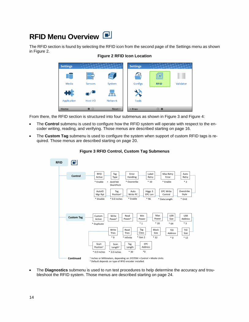
The RFID section is found by selecting the RFID icon from the second page of the Settings menu as shown in Figure 2.
Figure 2 RFID Icon Location
From there, the RFID section is structured into four submenus as shown in Figure 3 and Figure 4:
The Control submenu is used to configure how the RFID system will operate with respect to the en-coder writing, reading, and verifying. Those menus are described starting on page 16.
The Custom Tag submenu is used to configure the system when support of custom RFID tags is re-quired. Those menus are described starting on page 20.
Figure 3 RFID Control, Custom Tag Submenus
RFID
ControlRFID
Active
* Enable
TagType
• Aln9740 ShortPitch
ErrorHandling
* Overstrike
LabelRetry
* 10
Max RetryError
* Enable
AutoRetry
* 2
OverstrikeStyle
* Grid
EPC WriteControl
* Data Length
Higgs 3EPC Len
* 96
AutoWrite PC
* Enable
TagPosition1
* 0.0 inches
AutoIDMgr Rpt
* Disable
Continued
CustomActive
* Duplicate
WritePower2
ReadPower2
MinPower
* 1
MaxPower
* 20
USRSize
* 64
TIDSize
* 12
TIDAddress
* 0
BlockSize
* 32
TagClass
* Gen 2
EPCAddress
*0
Tag Length
* 30
ScanLength1
* 3.0 inches
StartPosition1
* 0.0 inches
USRAddress
* 3
ReadTries
* Infinite
WriteTries
* 9
Custom Tag
1 Inches or Millimeters, depending on SYSTEM > Control > Media Units.2 Default depends on type of RFID encoder installed.
The Diagnostics submenu is used to run test procedures to help determine the accuracy and trou-bleshoot the RFID system. Those menus are described starting on page 24.
15
The Statistics submenu is general read-only and used to gather and report statistics on how the RFID system is reporting on print jobs sent to the printer. Those items are described starting on page 26.
Figure 4 RFID Diagnostics, Statistics Submenus
Diagnostics
Statistics
ReadTag
Read Tag& Eject
ReadTID
TagID
TagPC
Tag WriteCount
Tag FailedCount
Tag VoidCount
Tag ReadCount
Clear TagStats
RFID ReaderF/W
RFID
ReadPC
Read Only Read Only
Read Only Read Only Read Only Read Only Read Only
Write ECP with 1s
Write ECP with 2s
Configuring the RFID
Configuring the RFID is done by selecting the RFID icon within the Settings section. The RFID comes equipped with a default setting for each configuration option, and it works without having to change any of these options. However, in some cases it is necessary to adjust these options, which are described below.
IMPORTANT If you are unable to select the RFID icon or the icon is grey, then the RFID is not
properly installed. Refer to Section “Printronix Customer Support Center” for help
on how to solve this problem.
IMPORTANT If you make any changes to the default configuration menu items, you will be
prompted to save the configuration. See “Auto Save Configuration” in the
Administrator’s Manual.
Enabling and Disabling
Software can automatically detect an installed RFID when the printer is powered up. If the printer is powered up with Configs > Control > Power-Up Config set to “Factory”, the RFID icon can be selected and RFID > Control > RFID Active is set to “Enable”.
If Power-Up Config. is not set to Factory, the RFID icon can be selected, but RFID > Control > RFID Active is set to “Disable”. Set this menu to “Enable” and save the configuration as described in the Administrator’s Manual. In the same manner, the RFID can be disabled.
Checking Firmware Revision
For troubleshooting purposes, you may need to reference the RFID firmware revision number. This can be found in two different places within the Settings section:
RFID > Statistics > RFID Reader F/W.
TOOLS > About > RFID Reader F/W.

16
Reporting Statistics
After any completed print job, you can request a report from the printer which describes the RFID statistics since the printer was turned on, or since the last time the RFID > Statistics > Clear Tag Stats was executed.
Requesting an RFID/ODV Report
This procedure prints a summarized RFID report. (This report also includes Validator data if the printer has a Validator installed.)
1. Press the PAUSE key to take the printer OFFLINE.
2. If necessary, press the UP+DOWN ARROW keys at the same time to unlock the front panel.
3. Edit the menu Tools > Print Tests > Run Tests.
4. Find the printer test named “Valid. Report” and press the ENTER key.
5. Lock the panel again using the UP+DOWN ARROW keys.
6. Press PAUSE again to put the printer ONLINE.
Resetting RFID Data
The RFID statistics are kept since the last time the RFID > Statistics > Clear Tag Stats was executed. For example, you print a large batch of labels reading and writing RFID tags and then print an RFID/ODV report. Then you print/encode another batch of labels and print another report. The report will contain information on both batch jobs. However, if you reset the RFID data between batch jobs, the second report will only contain information on the second batch job.
To reset RFID Data, execute the menu RFID > Statistics > Clear Tag Stats.
Control Submenu
A number of RFID options which define specific parameters for certain print jobs can be set from the RFID > Control submenu.
RFID Active
RFID > Control > RFID Active
Software can automatically detect an installed RFID reader when the printer is powered up. If the printer is powered up with Configs > Control > Pow-er-Up Config set to “Factory”, the RFID icon can be selected and this option is set to “Enable”.
If Power-Up Config is not set to Factory, the RFID icon can be selected, but this option is set to “Disable”.
Disable The RFID function is disabled and not active.
Enable The RFID function is enabled and active.
Factory Default Depends on Configs > Control > Power-Up Config setting. See above.

17
Tag Type
RFID > Control > Tag Type
This menu item selects the tag type in use. Other types may be added in the future. See section Website Support on page 9 to view a current list on the website.
Alien® 9740 Sqlet See section Supported UHF Gen2 Tag Types on page
11 for lists of supported tag types in the order they appear in the menu (alphabetical order). …
S/Trac Web M5
Factory Default Set Automatically
Error Handling
RFID > Control > Error Handling
This menu item selects the error handling mode for RFID failures.
Overstrike
Each failed label prints with the Overstrike pattern and the form retries on a new label until the Label Retry count is exhausted. Whether or not an error message will display or the failed label will reprint depends upon the Max Retry Error setting.
None No specific action is taken when a tag fails to be pro-grammed.
Stop
The printer will halt and display the error message “RFID Error: Check Media.” The label is discarded and reprinting of the label (if desired) must be initiated from the host. When the error is cleared, the label with the failed tag moves forward until the next label is in posi-tion to be printed.
Factory Default Overstrike
Label Retry
RFID > Control > Label Retry
This menu item selects the number of label retries that the RFID encoder will attempt before declaring a fault. This may indicate a problem with the RFID encoder, the coupler assembly, the printer setup, or the label stock.
Minimum 1
Maximum 10
Factory Default 10
IMPORTANT Label Retry only applies when the Error Handling mode is set to Overstrike.

18
Max Retry Error
RFID > Control > Max Retry Error
This menu item determines if errors are declared when the Label Retry count is exceeded.
Disable Errors are not declared and the print content for the current label is discarded.
Enable Errors are declared when the tag cannot be pro-grammed within the Label Retry count.
Factory Default Enable
Auto Retry
RFID > Control > Auto Retry
This menu item selects the number of automatic (internal) retries that the printer will attempt on the same tag before taking action per the menu Error Handling.
Minimum 1
Maximum 9
Factory Default 2
Overstrike Style
RFID > Control > Overstrike Style
This menu item selects the style of the overstrike pattern.
Grid A grid pattern prints when it overstrikes. On the T6000, this will be a partial grid pattern.
Error Type Msg An error message prints that indicates which error occurred per Table 5.
Factory Default Grid
IMPORTANT
If you are using a validator, set the RFID Overstrike Style different than VALIDATOR > Control > Over-strike Style. This will help you differentiate errors.
EPC Write Ctrl
RFID > Control > EPC Write Ctrl
This option controls how the printer encodes the RFID tag EPC field.
Data Length Only the amount of data provided in the application is encoded.
Full EPC Length The maximum EPC length for the particular tag type in use is written to the tag (padded with zeroes if neces-sary).
Factory Default Data Length
IMPORTANT If Auto Write PC is enabled, the PC field encodes information about the length of the EPC written.

19
Higgs 3 EPC Len
RFID > Control > Higgs 3 EPC Len
Higgs 3 tags differ from other RFID tags in that its memory bank size is not fixed. To accommodate EPC lengths longer than 96 bits, Higgs 3 borrows memory from the USR bank.
Minimum 96
Maximum 496
Factory Default 96
IMPORTANT
When the EPC length is selected, the USR length sets automatically per Table 4.
Since the PC value indicates the length of the EPC in the Higgs 3, the PC value must be programmed when programming the EPC (if the EPC value has changed from its factory state). The PC value to be programmed for each of the supported EPC lengths is shown in Table 4.
Auto Write PC
RFID > Control > Auto Write PC
This option controls whether the printer automatically writes the RFID tag PC field to encode information about the length of the EPC field or whether the application is required to specify.
Disable The PC is not automatically written unless part of the application data.
Enable The PC is automatically written regardless of the ap-plication data.
Factory Default Enable
Tag Position
RFID > Control > Tag Position
This menu determines how far the RFID tag position of the currently installed tag differs from the RFID tag position of the standard Printronix tag. Printro-nix printers print at a maximum speed with RFID labels that have RFID tags in the standard position.
Minimum -1.0 inches
Maximum 5.0 inches
Factory Default 0.0 inches
IMPORTANT The units display in inches or millimeters, depend-ing on SYSTEM > Control > Media Units.

20
AutoID Mgr Rpt
RFID > Control > AutoID Mgr Rpt
This menu item enables AutoID and label information to be sent out the network port. This information can be used by an RFID tag data and labels manager program.
Disable No data is sent out the network port.
Enable Data is sent out the network port.
Factory Default Disable
Custom Tag Submenu
A number of RFID options which define specific parameters for custom RFID tags can be set from the RFID > Custom Tag submenu.
IMPORTANT When RFID > Custom Tag > Custom Active is enabled, these menus will be used by
the RFID encoder. When disabled, these menus will be ignored.
Custom Active
RFID > Custom Tag > Custom Active
This menu item enables or disables the custom tag menus.
Duplicate The settings of the selected Tag Type menu item are copied into the custom tag menus, but are ignored by the RFID encoder.
Disable Standard tags provided in section Supported UHF Gen2 Tag Types on page 11 will be used. The settings in this submenu are ignored by the RFID encoder.
Enable The RFID encoder uses the settings in the custom tag section, which must be set to match the characteristics of the custom tag.
Factory Default Duplicate
WARNING Printronix cannot guarantee the performance of tag types not certified by Printronix.
Write Power
RFID > Custom Tag > Write Power
This menu item selects the write power level to be used in the RFID encoder. 1 is the lowest power level setting, and 20 is the highest.
Minimum 1
Maximum 25
Factory Default Depends on the type of RFID encoder installed.
21
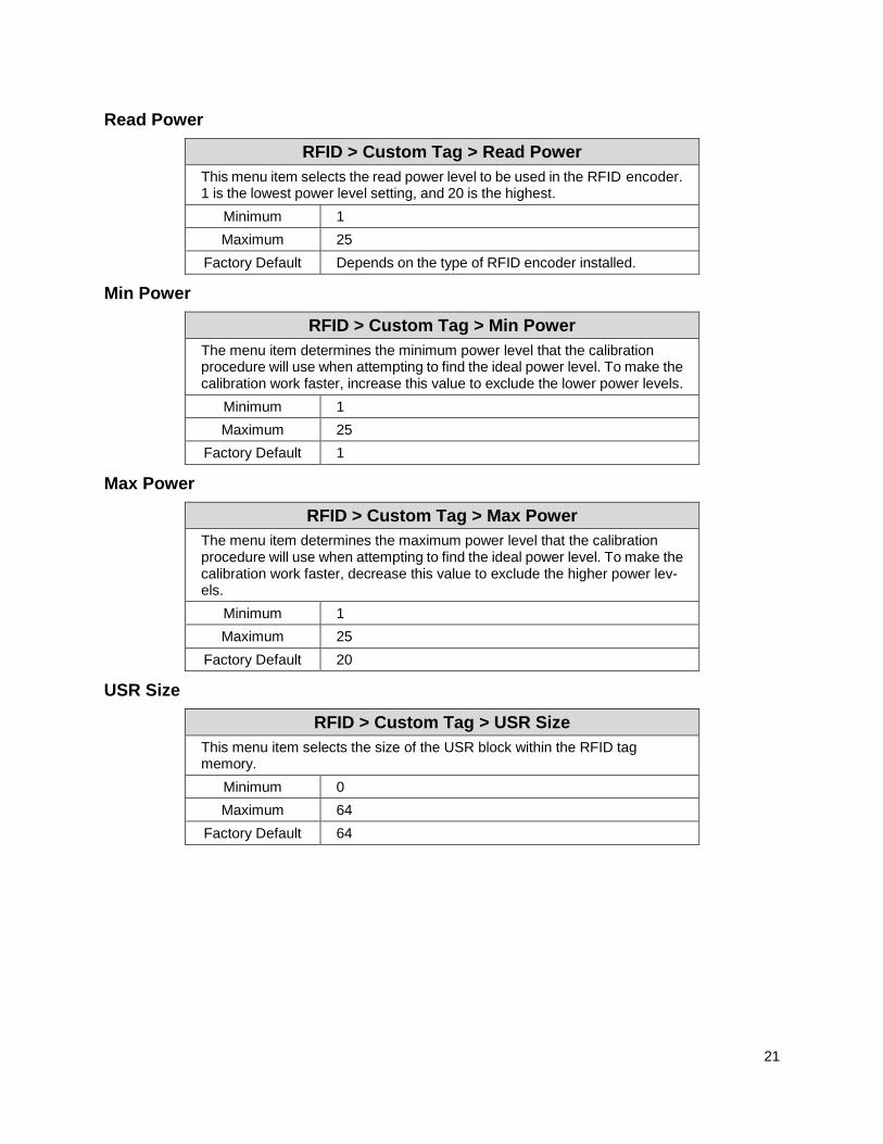
Read Power
RFID > Custom Tag > Read Power
This menu item selects the read power level to be used in the RFID encoder. 1 is the lowest power level setting, and 20 is the highest.
Minimum 1
Maximum 25
Factory Default Depends on the type of RFID encoder installed.
Min Power
RFID > Custom Tag > Min Power
The menu item determines the minimum power level that the calibration procedure will use when attempting to find the ideal power level. To make the calibration work faster, increase this value to exclude the lower power levels.
Minimum 1
Maximum 25
Factory Default 1
Max Power
RFID > Custom Tag > Max Power
The menu item determines the maximum power level that the calibration procedure will use when attempting to find the ideal power level. To make the calibration work faster, decrease this value to exclude the higher power lev-els.
Minimum 1
Maximum 25
Factory Default 20
USR Size
RFID > Custom Tag > USR Size
This menu item selects the size of the USR block within the RFID tag memory.
Minimum 0
Maximum 64
Factory Default 64

22
USR Address
RFID > Custom Tag > USR Address
This menu item selects the starting location of the USR block within the RFID tag memory.
Minimum 0
Maximum 32
Factory Default 3
TID Size
RFID > Custom Tag > TID Size
This menu item selects the size of the TID block within the RFID tag memory.
Minimum 0
Maximum 12
Factory Default 12
TID Address
RFID > Custom Tag > TID Address
This menu item selects the starting location of the TID block within the RFID tag memory.
Minimum 0
Maximum 32
Factory Default 0
Block Size
RFID > Custom Tag > Block Size
This menu item selects the maximum number of bytes written to the USR block within the RFID tag memory at one time.
Minimum 0
Maximum 32
Factory Default 32

23
Tag Class
RFID > Custom Tag > Tag Class
This menu item selects the class of the custom tag.
Class 1 Read/Write tag.
Gen 2 Read/Write tag.
Class 0 Read only
Class 0+ Read/Write tag.
Class 1.19 Read/Write tag.
Class Zuma Read/Write tag.
Factory Default Gen 2
Read Tries
RFID > Custom Tag > Read Tries
This menu item selects how many times the RFID encoder will try each read command.
Minimum 1
Maximum 10 or Infinite
Factory Default Infinite
Write Tries
RFID > Custom Tag > Write Tries
This menu item selects how many times the RFID encoder will try each write command.
Minimum 1
Maximum 10
Factory Default 9
Start Position
RFID > Custom Tag > Start Position
This menu item determines where on the label the RFID calibration will begin. By default, the calibration procedure will start at the beginning of the label (0.0 inches). To make the calibration work faster, change this value to force the calibration to begin after the beginning of the label.
Minimum 0.0 inches
Maximum 5.0 inches
Factory Default 0.0 inches
IMPORTANT The units display in inches or millimeters, depend-ing on SYSTEM > Control > Media Units.
24
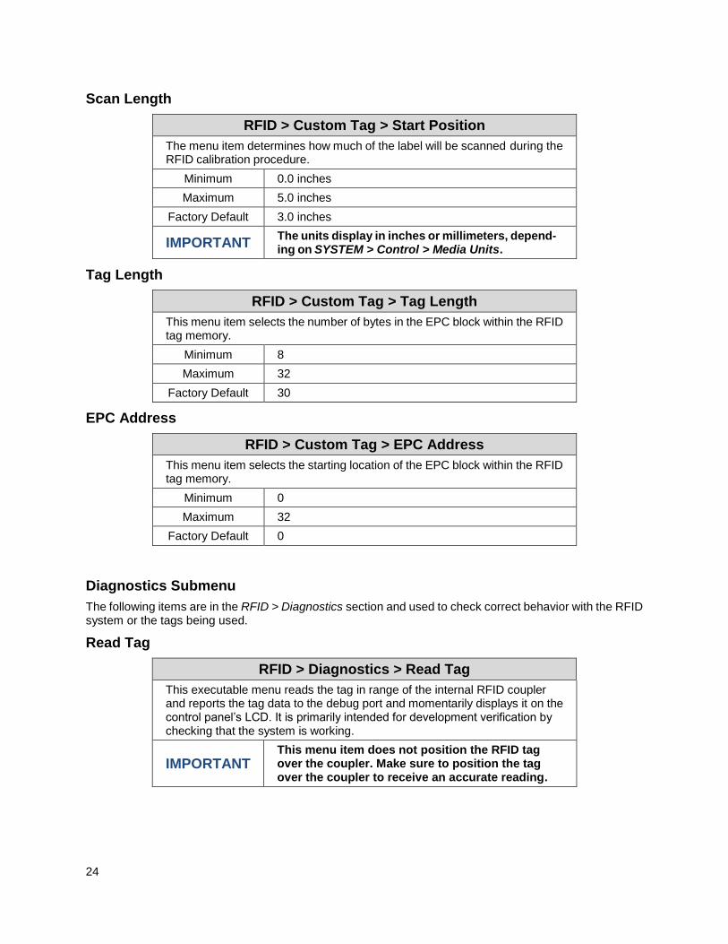
Scan Length
RFID > Custom Tag > Start Position
The menu item determines how much of the label will be scanned during the RFID calibration procedure.
Minimum 0.0 inches
Maximum 5.0 inches
Factory Default 3.0 inches
IMPORTANT The units display in inches or millimeters, depend-ing on SYSTEM > Control > Media Units.
Tag Length
RFID > Custom Tag > Tag Length
This menu item selects the number of bytes in the EPC block within the RFID tag memory.
Minimum 8
Maximum 32
Factory Default 30
EPC Address
RFID > Custom Tag > EPC Address
This menu item selects the starting location of the EPC block within the RFID tag memory.
Minimum 0
Maximum 32
Factory Default 0
Diagnostics Submenu
The following items are in the RFID > Diagnostics section and used to check correct behavior with the RFID system or the tags being used.
Read Tag
RFID > Diagnostics > Read Tag
This executable menu reads the tag in range of the internal RFID coupler and reports the tag data to the debug port and momentarily displays it on the control panel’s LCD. It is primarily intended for development verification by checking that the system is working.
IMPORTANT
This menu item does not position the RFID tag over the coupler. Make sure to position the tag over the coupler to receive an accurate reading.
25
Read Tag & Eject
RFID > Diagnostics > Read Tag & Eject
This executable menu works exactly the same as Read Tag executable, except that after the printer reads the tag, it feeds the label to the next top-of-form.
IMPORTANT
This menu item does not position the RFID tag over the coupler. Make sure to position the tag over the coupler to receive an accurate reading.
Read TID
RFID > Diagnostics > Read TID
This executable menu reads the TID (Tag ID) from the tag in range of the internal RFID coupler and displays the value read in the Tag ID menu.
IMPORTANT
This menu item does not position the RFID tag over the coupler. Make sure to position the tag over the coupler to receive an accurate reading.
Tag ID
RFID > Diagnostics > Tag ID
This menu item displays the first TID (Tag ID) read since power-up, or if us-ing the Read TID menu, the most recently read TID. If no tag is in range of the internal RFID coupler, “Unknown” displays.
Read PC
RFID > Diagnostics > Read PC
This executable menu reads the PC (Protocol Control) field from an RFID tag in range of the internal RFID coupler and displays the value read in the Tag PC menu.
IMPORTANT
This menu item does not position the RFID tag over the coupler. Make sure to position the tag over the coupler to receive an accurate reading.
Tag PC
RFID > Diagnostics > Tag PC
This menu item displays the last PC (Protocol Control) field read from an RFID tag. If no tag is in range of the internal RFID coupler, “Unknown” dis-plays.

26
Write EPC with 1s
RFID > Diagnostics > Write EPC with 1s
This executable menu writes all ones to the tag in range of the internal RFID coupler. It is primarily intended for development verification by checking that the system is working.
IMPORTANT
This menu item does not position the RFID tag over the coupler. Make sure to position the tag over the coupler to receive an accurate writing.
Write EPC with 2s
RFID > Diagnostics > Write EPC with 2s
This executable menu writes all twos to the tag in range of the internal RFID coupler. It is primarily intended for development verification by checking that the system is working.
IMPORTANT
This menu item does not position the RFID tag over the coupler. Make sure to position the tag over the coupler to receive an accurate writing.
Statistics Submenu
The following items are in the RFID > Statistics section and used to store statistics about the RFID system activities. The statistics can be reset by executing the menu Clear Tag Stats operation within this section.
Tag Write Count
RFID > Statistics > Tag Write Count
This menu item displays on the LCD the number of tags attempted to be written since the last Clear Tag Stat operation has been initiated.
Tag Failed Count
RFID > Statistics > Tag Failed Count
This menu item displays on the LCD the number of failed tag write attempts since the last Clear Tag Stat operation has been initiated.
Tag Void Count
RFID > Statistics > Tag Void Count
This menu item always displays 0 unless the RFID encoder is used with an attached online data validator. When used with a validator, Tag Void Cnt represents how many valid RFID tags were overstruck due to bad bar code scanning. Refer to the Online Data Validator User’s Manual.
Tag Read Count
RFID > Statistics > Tag Read Count
This menu item displays the number of tags read since the last Clear Tag Stat operation.

27
Clear Tag Stat
RFID > Statistics > Clear Tag Stat
This executable menu item clears the Count menu items in this submenu.
RFID Reader F/W
RFID > Statistics > RFID Reader F/W
Shows the RFID firmware version installed in the encoder.

28
RFID Commands
This section will cover different emulations that support RFID within the Printronix RFID thermal products:
Incorporate RFID commands into new or existing Printronix PGL® programs. Command details start on page 28.
Incorporate RFID commands into new or existing ZPL™ programs. By selecting the Printronix ZGL emulation you can seamlessly upgrade from Zebra™ printers. Command details start on page 42.
Incorporate RFID commands into new or existing SATO® printer language programs. By selecting the Printronix STGL emulation you can seamlessly upgrade from SATO printers. Command details start on 49.
PGL RFID Commands
IMPORTANT With all examples make sure MEDIA > Image > Label Length matches the physical
length of the installed media.
RFWTAG
Purpose The RFWTAG command is used to program an RFID tag (embedded in a smart
label) using structured data format. The data structure of an RFID tag can consist of
one or more bit fields. Each bit field specifies its own field length, the data format, the
field type plus additional options if the type is incremental, and finally the field value.
NOTE: The RFWTAG command is supported only on Thermal printers.
Mode CREATE
Format RFWTAG[;LOCKn[;format]];size[;mem bank]
(Bit Field)+
STOP
RFWTAG Specifies the RFWTAG command, enter RFWTAG;
LOCKn[;format] or PERMALOCKn[;format]
Optional parameter to lock the data block to prevent it from being
overwritten. By default, the data are not locked initially. n is the
passcode. The acceptable values for n are 1 to FFFFFFFF in hex, a
4 bytes data. When the LOCKn option is used to lock any memory
bank, which at the same time is programmed with the write data, the
same passcode will be written on ACS memory bank. The ACS
memory bank will also be locked if ACS is not locked at the time of
the operation. If ACS is already locked at the time of the operation,
the passcode needs to match the current content of ACS so that the
memory bank lock takes effect. The passcode (n) can also be in
dynamic format. For dynamic format, enter LOCK<DFn>, where
DFn is the dynamic field defined in EXECUTE mode. Both LOCK

29
and PERMALOCK share the same syntax. For differences in
functionality, see Note 12 on page 31.
format An optional parameter to specify the format for the passcode data.
Enter B for binary, D for decimal, and H for hexadecimal. The default is
decimal if format is not specified.
size A decimal number specifying the overall bit length of the memory
bank.
mem bank Specifies which tag logical memory area that this command will be
applied. If omitted, it defaults to the EPC memory area. Other areas
include Identification, User Data, Access area and Kill area. Enter one
of the following values:
‘EPC’ – EPC 12 bytes data area (default)
‘TID’ – Tag identification 8 bytes area (currently not applicable for RFWTAG)
‘USR’ – User 32 bytes area
‘ACS’ – 4 bytes access code area
‘KIL’ – 4 bytes kill code area
‘PC’ – 2 bytes PC code area (Gen 2 tags only)
NOTE: New tags, such as RSI IN47 Crkscr, support 240 bits of EPC memory and 512 bits of USR memory.
Bit Field A line description of a bit field and must have one of the following
syntax formats:
1. For non-incremental data (both static and dynamic)
length;[DFn;]format;(D)datafield(D)
2. For incremental fixed data
length;I;format;STEP[idir]step;[RPTn;]
[RSTn;](D)startdata(D)
3. For dynamic incremental data
length;IDFn;format;
length A decimal number specifying the bit length of a field within a tag. The
maximum length for each DFn field of NON-HEX format is 64 bits. For
hexadecimal format, the bit length can be up to the maximum bit length
specified for the corresponding memory bank.
DFn Optional parameter to indicate this field has dynamic data. Replace
n with a number ranging from 1 to 512 to identify the field number of
this particular field. If this option is used, datafield is ignored, and
dynamic data must be entered via the DF command in the
EXECUTE mode.
IDFn Enter IDF to indicate this field is a bit field with dynamical
assignment of increment (or decrement) data. The step and
startdata parameters will be supplied by the IDF command in the
EXECUTE mode. Replace n with a number ranging from 1 to 512
to identify the field number of this bit field. Dynamically enter the
step and startdata parameters using the IDF command in the
EXECUTE mode.
NOTE: 1. The same field number cannot be used in both DFn and IDFn.

30
2. If a field is defined as IDFn, it must be referenced as IDFn later for consistency. The same
applies for DFn.
3. If <IDFn> syntax is used for merging data into AFn or BFn, neither DFn, AFn, or BFn will
be incremented. The increment only takes place in the ~DFn command where the STEP
is specified.
format A letter specifying the format of the data field.
B – binary, D – decimal, H – hexadecimal
(D) Delimiter designating the start and end of static data for this bit
field. Replace (D) with any printable character, except the SFCC
and the slash character (/).
datafield The static data of this static field. It is a mandatory parameter of bit
field with static data.
I Identifies this field is an incremental bit field.
STEP Specifies that the incremental data field will use the step method.
Enter STEP;. The STEP option replaces the STEPMASK option
that is used in Alpha and Barcode.
idir Enter a plus sign (+) or leave the field blank to increment
(default). Enter a minus sign (–) to decrement.
step A decimal number specifies the amount to increment/decrement
each time the form is executed. The increment is at bit level and will
automatically wrap based on the field size.
RPTn The optional incremental repeat count parameters to specify the
number of times a particular field value is repeated before it is
incremented. The default repeat count parameter n is 1, which will
increment the field value each time it prints. The repeat count can
range from 1 to 65535.
RSTn The optional incremental reset count parameter to specify the
number of times an incremented field is printed before it is reset to
the starting value. By default, there is no reset count. The reset
count parameter n can range from 1 to 65535.
startdata Defines the value of the field or the starting value of the incremented
field. If the field is dynamic, the value will be specified later in the
EXECUTE mode. The data must be specified within a pair of delimiters
(D). The delimiter (D) cannot be a “/” or SFCC character since the “/”
will comment out the rest of the line and SFCC is reserved for PGL
commands. If “R” or “S” is used as delimiters, the data pattern must not
comprise of the keywords in the incrementing options. Since the
delimiters could be different from one value to another, proper care
must be taken to avoid one of the letters mentioned above.

31
NOTE: 1. The RFWTAG command cannot be mixed with RFWRITE in the same form.
2. Each field structure must be specified in a single line and in the order it appears in the RFID tag from MSB bits to LSB bits (left to right). The sum of all the field lengths must match the size of the tag.
3. The host data are read in as ASCII characters. They would be converted to binary representation for the base field on the field format. Therefore, if the converted value is larger than the maximum value that a field can hold, an error will be reported. If the data value is smaller than the specified field length, on the other hand, the field will be padded to the left with zero bits.
4. Unlike the Alpha and Barcode command which use STEPMASK for incremental data, RFWTAG uses the STEP which will increment or decrement at bit level.
5. 432 IGP dots in the ~CREATE line specifies a 6 inch label. 6 inches = 432 (IGP dots)/72 (dpi)
Use 144 for 2 inch labels and 288 for 4 inch labels.
6. ACS and KIL are similar to other memory banks. ACS contains the passcode which is used for LOCK and UNLOCK operations. KIL contains the killcode which is used to kill a tag. The user can write to or read from KIL memory bank, but the functionality of killing a tag is not currently applicable. Also, once ACS and KIL are locked, both cannot be written to or read from. For other memory banks, EPC, USR, and TID, once locked, they can be read from but not written to.
7. There are two ways to program the ACS memory area. One is to write to the ACS memory area directly with RFWTAG. The other is to use the LOCK option while writing to other memory banks. If ACS is not previously locked, then LOCK option will lock the memory bank and also write the passcode to ACS and lock ACS. When write to ACS with RFWTAG, ACS is not automatically locked. To lock ACS, use LOCKn with RFWTAG, where the passcode (n) should be the same as the write data to ASC.
8. There is only one passcode, the content of ACS memory bank, for each tag. The same passcode is used to lock or unlock any memory bank in that tag.
9. For LOCKn and UNLOCKn, the passcode (n) (which includes the dynamic format <DFn>) does not accept incremental data. This also applies to the ACS and KIL memory banks. The write data to the ACS and KIL memory banks do not accept incremental data because the ACS memory bank contains passcodes for LOCK and UNLOCK operations, and the KIL memory bank contains a killcode to kill a tag. Incremental data do not apply to passcodes or killcodes.
10. When LOCK<DFn> and UNLOCK<DFn> are used in the same form with the same dynamic data (the passcode), the dynamic format <DFn> needs to be a different dynamic number for LOCK and UNLOCK since it is designed with a unique dynamic number that can be linked to only one object type. In this case, LOCK is linked to RFWTAG object and UNLOCK is linked to RFRTAG object. Although both options use the same passcode, the dynamic format needs to be in a different dynamic number in the same form.
11. Because PC field is related to EPC field, when PC RFWTAG is used in the form, it must be followed immediately by EPC RFWTAG, or else an error will be reported. Also, by specification, the first 5 bits of PC data need to comply with the length of EPC data, or else an error will be reported. For example, for 96 bits EPC, the 5 bits of PC data is 00110. For 64 bits EPC, the first 5 bits of PC data is 00100. Also, LOCK option is not and will not be supported for PC field, since PC field works with EPC field (which already supports LOCK option).
12. Both LOCK and PERMALOCK requires the user to enter the password. Once the tag is permanently locked with the PERMALOCK command, it cannot be unlocked again; the tag can only be read from and never be written to once it is permanently locked. On the other hand, after the tag is locked with the LOCK command, it can be unlocked again with the same password.

32
For PERMALOCK (ex, EPC), the password must match the current content of ACS bank for PERMALOCK to work. If the current content of ACS bank is null (0x0) which could be the case for the brand new tag, the password for PERMALOCK EPC will be 0x0. If you use a different password for PERMALOCK, you need to write (RFWTAG) the new content (password) to ACS first, and then use this new password to PERMALOCK EPC.
For LOCK (ex, EPC), the password may be different from the current content of ACS. When a new password is used to lock EPC where ACS is not locked, this new password is written to ACS and locks ACS at the same time while locking EPC. For new tags where ACS is not locked and has all null data, you can lock EPC with a new password directly without writing to ACS first.
Example 1
The following example programs an SGTIN–64 value into the RFID tag that is embedded in a 4x6 smart label. Assume that the SGTIN–64 value is provided as a single number. ~CREATE;SGTIN–64;432 RFWTAG;64 64;H;*87D0034567ABCDEF* /EPC number STOP END ~EXECUTE;SGTIN–64;1 ~NORMAL
Example 2
Same as Example 1, except the EPC number is broken into its component parts. Assume that the SGTIN–64 value has the Header = 2d, Filter Value = 5d, EPC Manager Index = 15383d, Object Class = 703710d or 0xABCDE, and the Serial Number = 0123456d.
~CREATE;SGTIN–64;432
RFWTAG;64 2;B;*10* /Header 3;D;*5* /Filter Value 14;D;*15383* /EPC Manager Index 20;H;*ABCDE* /Object Class 25;D;*0000123456* /Serial Number
STOP
END ~EXECUTE;SGTIN–64;1 ~NORMAL
Example 3
Same as Example 2, except it uses a dynamic method. This example also shows how to program another RFID tag without redefining the data structure of the SGTIN–64.
~CREATE;SGTIN–64;432
RFWTAG;64 2;DF1;B /Header 3;DF2;D /Filter Value 14;DF3;D /EPC Manager Index 20;DF4;H /Object Class 25;DF5;D /Serial Number
STOP
ALPHA
33
AF1;18;10;5;3;3
STOP
END ~EXECUTE;SGTIN–64 ~DF1;*10* /Header ~DF2;*5* /Filter Value ~DF3;*15383* /EPC Manager Index ~DF4;*ABCDE* /Object Class ~DF5;*0000123456* /Serial Number ~AF1;<DF5> /Print serial number on label ~NORMAL ~EXECUTE;SGTIN–64 ~DF1;*10* /Header ~DF2;*5* /Filter Value ~DF3;*15383* /EPC Manager Index ~DF4;*ABCDE* /Object Class ~DF5;*0000123456* /Serial Number
~AF1;<DF5> ~AF1;<DF5> /Print serial number on label
~NORMAL
Example 4
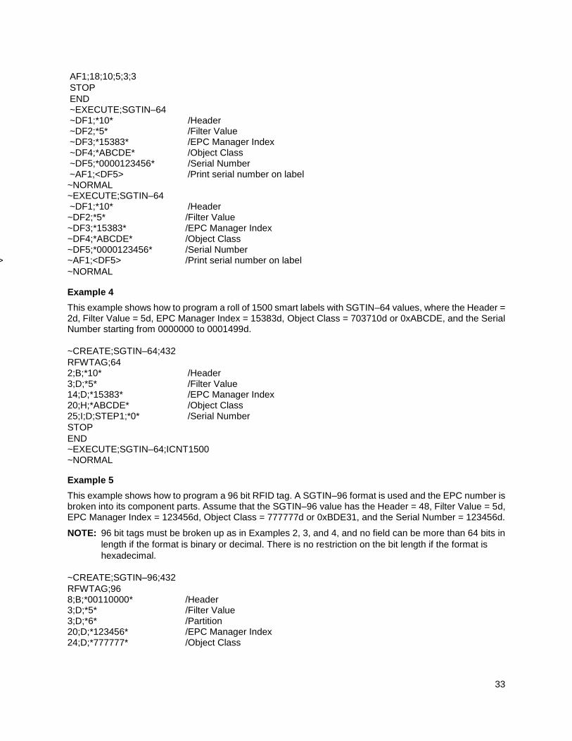
This example shows how to program a roll of 1500 smart labels with SGTIN–64 values, where the Header = 2d, Filter Value = 5d, EPC Manager Index = 15383d, Object Class = 703710d or 0xABCDE, and the Serial Number starting from 0000000 to 0001499d.
~CREATE;SGTIN–64;432
RFWTAG;64 2;B;*10* /Header 3;D;*5* /Filter Value 14;D;*15383* /EPC Manager Index 20;H;*ABCDE* /Object Class 25;I;D;STEP1;*0* /Serial Number
STOP
END ~EXECUTE;SGTIN–64;ICNT1500 ~NORMAL
Example 5
This example shows how to program a 96 bit RFID tag. A SGTIN–96 format is used and the EPC number is broken into its component parts. Assume that the SGTIN–96 value has the Header = 48, Filter Value = 5d, EPC Manager Index = 123456d, Object Class = 777777d or 0xBDE31, and the Serial Number = 123456d.
NOTE: 96 bit tags must be broken up as in Examples 2, 3, and 4, and no field can be more than 64 bits in
length if the format is binary or decimal. There is no restriction on the bit length if the format is
hexadecimal.
~CREATE;SGTIN–96;432
RFWTAG;96 8;B;*00110000* /Header 3;D;*5* /Filter Value 3;D;*6* /Partition 20;D;*123456* /EPC Manager Index 24;D;*777777* /Object Class

34
38;D;*123456* /Serial Number
STOP
END ~EXECUTE;SGTIN–96;1 ~NORMAL Example 6
This example shows memory bank usage, where multiple RFWTAG and RFRTAG can be used. ~CREATE;SGTIN;216 SCALE;DOT;203;203 RFWTAG;96;EPC 96;IDF1;H STOP RFRTAG;96;EPC 96;DF3;H STOP RFWTAG;256;USR 256;IDF2;H STOP RFRTAG;256;USR 256;DF4;H STOP ALPHA IAF1;24;POINT;90;60;16;6 IAF2;64;POINT;130;60;16;4 STOP BARCODE C3/9;X1;IBF1;64;170;60 PDF STOP VERIFY;DF1;H;*EPC W= *;*\r\n* VERIFY;DF3;H;*EPC R= *;*\r\n* VERIFY;DF2;H;*USR W= *;*\r\n* VERIFY;DF4;H;*USR R= *;*\r\n* END ~EXECUTE;SGTIN;ICNT4 ~IDF1;STEP+1;*313233343536373839414243* ~IDF2;STEP+1;*3132333435363738394142434445464748494A
4B4C4D4E4F*
~IAF1;<DF3> ~IAF2;<DF4> ~IBF1;<DF3> ~NORMAL
Example 7
This example shows memory bank usage with LOCK and UNLOCK option, where multiple RFWTAG and RFRTAG can be used, and the passcode for lock and unlock can be in dynamic format.
~CREATE;SGTIN;432

35
SCALE;DOT;203;203
RFWTAG;LOCK<DF6>;D;96;EPC
96;DF1;H
STOP
RFRTAG;UNLOCK<DF6>;D;96;EPC
96;DF2;H
STOP
RFWTAG;LOCKA1B2C3;H;32;KIL
32;DF3;H
STOP
RFRTAG;UNLOCKA1B2C3;H;32;KIL
32;DF4;H
STOP
RFWTAG;LOCK<DF7>;H;32;ACS
32;DF6;D
STOP
RFRTAG;UNLOCK<DF7>;H;32;ACS
32;DF8;H
STOP
ALPHA
AF1;24;POINT;400;60;16;6
AF2;7;POINT;600;60;16;6
AF3;6;POINT;800;60;16;6
AF4;8;POINT;1000;60;16;6
STOP
VERIFY;DF1;H;*DF1 = *;*\r\n*
VERIFY;DF2;H;*DF2 = *;*\r\n*
VERIFY;DF4;H;*DF4 = *;*\r\n*
VERIFY;DF5;H;*DF5 = *;*\r\n*
VERIFY;DF6;H;*DF6 = *;*\r\n*
VERIFY;DF7;H;*DF7 = *;*\r\n*
VERIFY;DF8;H;*DF8 = *;*\r\n*
END
~EXECUTE;SGTIN;FCNT3 ~DF1;*313233343536373839414243* ~DF3;*3435363738* ~DF6;*3224115* ~DF7;*A1B2C3* ~AF1;<DF2> ~AF2;<DF6> ~AF3;<DF7> ~AF4;<DF8> ~NORMAL
Example 8
This example shows the usage of RFWTAG with PC field which needs to be followed immediately by RFWTAG with EPC field. There is not restriction for RFRTAG with PC filed. ~NORMAL

36
~CREATE;TEST1;432
RFWTAG;16;PC
16;H;*3000*
STOP
RFWTAG;96;EPC
96;H;*313233343536373839414243*
STOP
RFWTAG;256;USR
256;H;*3132333435363738394142434445464748494A4B*
STOP
RFRTAG;16;PC
16;DF1;H
STOP
RFRTAG;96;EPC
96;DF2;H
STOP VERIFY;DF1;H;*DF1 = *;*\r\n*
VERIFY;DF2;H;*DF2 = *;*\r\n*
END
~EXECUTE;TEST1 ~NORMAL
Example 9
This example shows the usage of PERMALOCK. ~NORMAL ~CREATE;RFID;432
ALPHA
IAF1;24;POINT;4;5;10;10
STOP
RFWTAG;32;ACS
32;H;*ABC*
STOP
RFWTAG;PERMALOCKABC;H;96;EPC
96;IDF1;H
STOP
RFRTAG;96;EPC
96;DF2;H
STOP
VERIFY;DF2;H;* *
END
~EXECUTE;RFID;ICNT5
IDF1;STEP+1;*222222222222222222220011*
IAF1;<DF2>
~NORMAL
Example 10
This example shows the access of 240 bits EPC and 512 bits USR.
~CREATE;TEST;X;NOMOTION
RFWTAG;LOCK0C0D0E0F;H;240;EPC
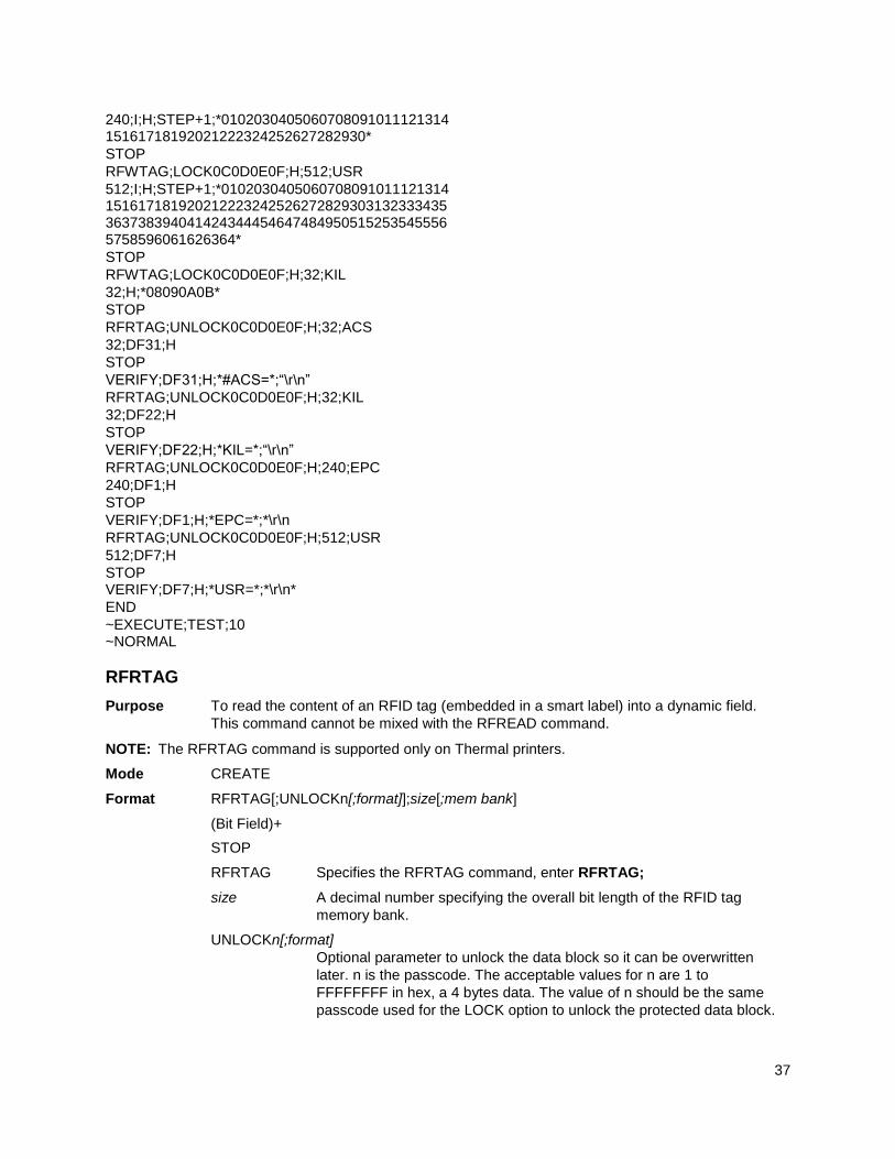
37
240;I;H;STEP+1;*0102030405060708091011121314 15161718192021222324252627282930*
STOP
RFWTAG;LOCK0C0D0E0F;H;512;USR
512;I;H;STEP+1;*0102030405060708091011121314 151617181920212223242526272829303132333435 363738394041424344454647484950515253545556 5758596061626364*
STOP
RFWTAG;LOCK0C0D0E0F;H;32;KIL
32;H;*08090A0B*
STOP
RFRTAG;UNLOCK0C0D0E0F;H;32;ACS
32;DF31;H
STOP
VERIFY;DF31;H;*#ACS=*;“\r\n”
RFRTAG;UNLOCK0C0D0E0F;H;32;KIL
32;DF22;H
STOP
VERIFY;DF22;H;*KIL=*;“\r\n”
RFRTAG;UNLOCK0C0D0E0F;H;240;EPC
240;DF1;H
STOP
VERIFY;DF1;H;*EPC=*;*\r\n
RFRTAG;UNLOCK0C0D0E0F;H;512;USR
512;DF7;H
STOP VERIFY;DF7;H;*USR=*;*\r\n*
END
~EXECUTE;TEST;10 ~NORMAL
RFRTAG
Purpose To read the content of an RFID tag (embedded in a smart label) into a dynamic field.
This command cannot be mixed with the RFREAD command.
NOTE: The RFRTAG command is supported only on Thermal printers.
Mode CREATE
Format RFRTAG[;UNLOCKn[;format]];size[;mem bank]
(Bit Field)+
STOP
RFRTAG Specifies the RFRTAG command, enter RFRTAG;
size A decimal number specifying the overall bit length of the RFID tag
memory bank.
UNLOCKn[;format]
Optional parameter to unlock the data block so it can be overwritten
later. n is the passcode. The acceptable values for n are 1 to
FFFFFFFF in hex, a 4 bytes data. The value of n should be the same
passcode used for the LOCK option to unlock the protected data block.
38
When the UNLOCKn option is used to unlock any memory bank, which
at the same is programmed to read the tag, the operation UNLOCKn
will not unlock ACS memory area. The passcode (n) can also be in
dynamic format. For dynamic format, enter LOCK<DFn>, where DFn is
the dynamic field defined in EXECUTE mode.
format is the optional parameter to specify the format for the
passcode data. Enter B for binary, D for decimal, and H for
hexadecimal. The default is decimal if format is not specified.
mem bank Specifies which tag logical memory area that this command will be
applied. If omitted, it defaults to the EPC memory area. Other areas
include Identification, User Data, Access area, and Kill area. Enter
one of the following values:
‘EPC’ – EPC 12 bytes data area (default)
‘TID’ – Tag identification 8 bytes area
‘USR’ – User 32 bytes area
‘ACS’ – 4 bytes access code area
‘KIL’ – 4 bytes kill code area
‘PC’ – 2 bytes PC code area (Gen 2 tags only)
Bit Field A line description of a bit field; must have one of the following syntax
formats:
length;DFn;format
length A decimal number specifying the bit length of a field
within a tag. The maximum length is 64 bits for
binary or decimal format. For hexadecimal format,
the bit length can be up to the maximum bit length
specified for the corresponding memory bank.
DFn Indicate dynamic data field to store the read result.
Replace n with a number ranging from 1 to 512 to
identify the field number of this particular field.
format A letter specifying the representation
format of the field data.
B – binary, D – decimal,
H – hexadecimal
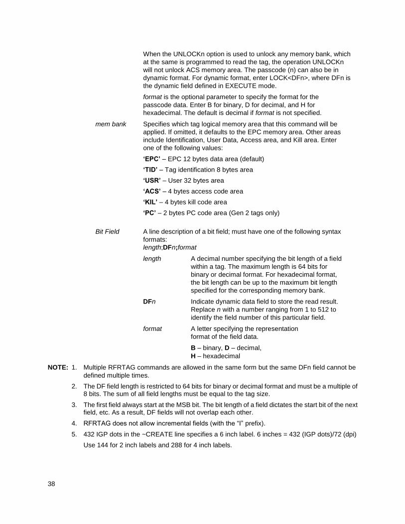
NOTE: 1. Multiple RFRTAG commands are allowed in the same form but the same DFn field cannot be
defined multiple times.
2. The DF field length is restricted to 64 bits for binary or decimal format and must be a multiple of 8 bits. The sum of all field lengths must be equal to the tag size.
3. The first field always start at the MSB bit. The bit length of a field dictates the start bit of the next field, etc. As a result, DF fields will not overlap each other.
4. RFRTAG does not allow incremental fields (with the “I” prefix).
5. 432 IGP dots in the ~CREATE line specifies a 6 inch label. 6 inches = 432 (IGP dots)/72 (dpi)
Use 144 for 2 inch labels and 288 for 4 inch labels.

39
Example
Same as Example 4 on page 33, except the increment is dynamic and the result is merged into Alpha to print on the smart label.
~CREATE;SGTIN–64;432
RFWTAG;64 2;B;*10* /Header 3;D;*5* /Filter Value 14;D;*15383* /EPC Manager Index 20;D;*123456* /Object Class 25;IDF1;H /Serial Number STOP
RFRTAG;64
64;DF2;H;
STOP
ALPHA
IAF1;16;3;12;0;0
STOP
END ~EXECUTE;SGTIN–64;ICNT1500 ~IDF1;STEP+1;*0* ~IAF1;<DF2>
~NORMAL
NOTE: 1. The <IDF1> usage does not increment the DF1 field. It merges the DF1 content into the AF1
field, keeping the same representation previously defined for IDF1.
2. The use of IAF1 is to print alpha on every label. If AF1 is used instead, only the first label is printed. The AF1 field is not incremented either since it is using the result from the DF1 merge.
VERIFY
Purpose Request the printer to send to the host the ASCII representation of a dynamic field. The
dynamic field could be one of AFn, BFn, or DFn, but cannot be RFn.
NOTE: The Verify command is supported only on Thermal printers.
Mode CREATE
Format VERIFY;field;format;(D)ASCIIheader(D);(D)ASCIITrailer(D)
VERIFY The command to verify data of a dynamic field, enter VERIFY;
field The dynamic field AFn, BFn, or DFn that contains the data to be sent
to the host.
format A letter specifying the format of the outgoing data to be sent to the host.
B – binary, D – decimal, H – hexadecimal, S – string
Based on the incoming format of the data field, a format conversion
may be performed if the outgoing format is not the same. The AFn and
BFn format is always S type. The DFn format could be either B, D, or H.
Due to the possible conversion the outgoing data stream could be
longer than the incoming one. The maximum length for the outgoing
data is 512 bytes. If the format request will result in a data stream
exceeding the maximum length, an error would be reported.

40
ASCIIheader A mandatory parameter to specify an ASCII string of characters, which is followed by the RFID data, to be sent by the printer to the host.
ASCIItrailer An optional parameter to specify an ASCII string of characters, which
will follow the RFID data, to be sent by the printer to the host.
(D) Delimiter designating the start and end of a character string. Replace
(D) with any printable character, except the SFCC and the slash
character (/). The string could be empty, i.e. there are not headers
preceding the field data.
NOTE: 1. The DFn field must be defined previously in the CREATE mode before it can be specified in the
VERIFY command otherwise it will be considered as a syntax error and the VERIFY command
will abort.
2. All RFID Read/Write commands are executed first in the order they appear in CREATE mode, followed by Alpha and Barcode commands, and finally VERIFY commands. The VERIFY commands are always executed last although they may appear before other commands in the CREATE mode. The reason for this is to make sure the data are sent back to the host only if other commands are completed and the form is not aborted.
3. If the data comes from a DFn field, the DFn format is the original format before any conversion. If the VERIFY command specifies a different format, the data would then be converted to the new format. If the data comes from an AFn or BFn, the original format is S format.
4. Below is the possible syntax for header and trailer string,
1, VERIFY;DF2;H;*Head = * //Header only
2, VERIFY;DF2;H;*Head = *; *Tail* //Header & trailer
3, VERIFY;DF2;H;**;*Tail* //Trailer only
4, VERIFY;DF2;H;*Head = *;** //Header only
To insert the CR/LF character, add “\r” and “\n” as CR/LF characters, such as
VERIFY;DF2;H;*Head=*; *Tail\r\n* //this will display “Head=<tag data>Tail<CR><LF>”
If the user wants to display “\r” or “\n” as normal text character, do the following:
VERIFY;DF2;H;*Header\\r\\n* //this will display “Header\r\n” on the screen, where double back slash “\\” (0x5C 0x5C) will be replaced with one back slash ‘\’ (0x5C).
The characters \r and \n can be inserted anywhere in the header string and trailer string.
To summarize,
\r –> 0x0D //CR
\n –> 0x0A //LF
\\ –> \ //one back slash
Example 1
This example requests the printer to send to the host the content of the RFID tag, in hexadecimal format, both before and after the RFWTAG command writes data to the tag. Also, the label is not moved.
~CREATE;VERIFY;432;NOMOTION
RFRTAG;64 64;DF1;H STOP VERIFY;DF1;H;*TagBefore=* RFWTAG; 64

41
2;B;*01* 6;D;*29* 24;H;*466958* 17;H;*ABC* 15;D;*1234* STOP RFRTAG;64 64;DF2;H STOP VERIFY;DF2;H;*TagAfter=* END ~EXECUTE;VERIFY;1 ~NORMAL TagBefore=A5A500005D055E04 <== Whatever data inside the tag before TagAfter=5D466958055E04D2 <== Should match with RFWTAG command
Example 2
This example reads a roll of 1500 pre-programmed smart labels.
~CREATE;READONLY;432
RFRTAG;64 64;DF1;H STOP VERIFY;DF1;H;** END ~EXECUTE;READONLY;1500 ~NORMAL A5A500005D055E04 <== Whatever data.... another 1498 lines of RFID data................. A5A50000000550D4 <== Whatever data
Example 3
This example requests the printer to program a roll of 2000 smart labels using the RFWTAG command with incremental field. Then, it sends the actual data from each of the 2000 tags to the host.
~CREATE;SIMPLE;432;NOMOTION
RFWTAG;64 2;B;*01* 6;D;*29* 24;H;*466958* 17;H;*ABC* 15;I;D;STEP+1;*0000*
STOP
RFRTAG; 64
64;DF1;H
STOP
VERIFY;DF1;H;*Data=*
END
~EXECUTE;SIMPLE;ICNT2000

42
~NORMAL Data=5D466958055E0000 <== Should be the newly
programmed data. Data=5D466958055E0001 ....another 1996 lines of
RFID data ................. Data=5D466958055E07CE Data=5D466958055E07CF <== Should be the newly
programmed data
ZGL RFID Commands
Read Tag ^RT
Purpose This command allows data from the RFID tag (embedded in the smart label) to merge into any
previously defined dynamic data field. It is equivalent to the Field Number command (^FN)
except that the data come from the RFID tag.
Format ^RT x, start, length, hex, retries, motion, reserved
^RT Read Tag command.
x Specified Field Number (value assigned to the field). The default is 0. The
acceptable value range is 0 to 9999.
start Location where data will be read from the RFID tag. The ZGL only supports Alien
Technology Class 1a tags, which have only one 8–byte or 12–byte block.
Therefore, start will be set to 0, regardless of the specified value.
length The number of blocks to be read from the RFID tag. The ZGL only supports Alien
Technology Class 1a tags, which have only one 8–byte or 12–byte block.
Therefore, length will be set to 1, regardless of the specified value.
hex This flag indicates whether the data, after being read from the RFID tag, should be
translated into hexadecimal format. The default is 0, meaning the data will not be
translated. The other acceptable value is 1, meaning the data will be translated
into hexadecimal format.
retries The number of automatic attempts to read data from the tag if previous reads
failed. The ZGL absorbs the number and uses the value on the control panel’s
LCD.
motion Set this flag to 1 to read data from the tag without moving the label. The printer
may adjust the label position while it reads data from the tag, but this adjustment
will reverse before any subsequent normal label movement. Even if this flag is set
to 1, other commands (i.e., alpha or barcode) may move the label.
reserved This is a reserved flag. The ZGL absorbs this number.
Comments This command is only executed by the demand for data from any dynamic field. The ZGL ab-sorbs this command if there are no demands for the data

43
Write Tag ^WT
Purpose This command programs data into an RFID tag (embedded in the smart label).
Format ^WT start, retries, motion, protect, data format, reserved
^WT Write Tag command.
start Starting block location where data will be programmed into the RFID tag. The
ZGL only supports Alien Technology Class 1a tags, which have only one 8–
byte or 12–byte block. Therefore, start will be set to 0, regardless of the
specified value.
retries The number of automatic attempts to write data into the tag if previous writes
failed. The ZGL absorbs the number and uses the value on the control panel’s
LCD.
motion Set this flag to 1 to program data into the tag without moving the label. The
printer may adjust the label position while it writes data into the tag, but this
adjustment will reverse before any subsequent normal label movement. Even if
this flag is set to 1, other commands (i.e., alpha or barcode) may move the label.
protect This flag indicates whether the data should be protected from being overwritten
later. The default is 0, meaning the data are not protected. Other acceptable
values are 1 to 255, meaning the data are protected using this number as the
LOCK password.
Data format 0 (ASCII) or 1 (hex). The default is 0.
reserved This is a reserved flag. The ZGL absorbs this number.
Write or Read Format ^RF
Purpose This command allows you to write or read to an RFID tag.
Format ^RFa,b,c,d,e
^RF Write or Read RFID command.
a Specifies the read or write option. The default is W.
W = write to the tag
L = write with LOCK
R = read the tag
P = read password (Gen 2 tags only; used when c is set to K or A).
b Specifies the data format. The default is H.
A = ASCII
H = Hex
E = EPC format.
c Specifies the starting block number. The default is 0. Since there are currently
only 8–byte or 12–byte blocks, the starting block number can only be 0. Or,
specifies which password to read (Gen 2 tags only; used when a is set to P):
K = kill password
44
A = access password
d Specifies the number of blocks to read. This option is valid only for the read
operation. Since there are currently only 8–byte or 12–byte blocks, the number of
blocks to be read can only be 1.
e Specifies the memory bank to write to or read from. The default is E.
E = EPC
0 = Reserved
1 = EPC
2 = TID (only for read)
3 = USER
Calibrate Transponder ^HR
Purpose This command initiates an RFID transponder calibration for a specific RFID label and returns
the results to the host computer.
Format ^HRa,b
^HR Calibrate RFID command.
a The start string to appear before the returned result. The default is “start”. The ac-ceptable value is any string less than 65 characters.
b The end string to appear after the returned result. The default is “end”. The acceptable value is any string less than 65 characters.
Define EPC Data Structure ^RB
Purpose This command defines the structure of EPC data, which can be read from or written to an
RFID transponder.
Format ^ RBp0,p1,p2...,p15
^RB EPC Data command.
n Total bit size of the field. The default is 96. The acceptable value range is 1 to n, where n is the total bit size of the tag.
p1..p15 Specifies each partition size. These must add up to the total bit size. The default is 1. The acceptable value range is 1 to 64 bits for each partition.
Enable RFID Motion ^RM
Purpose This command enables or disables RFID paper motion. Be default, labels automatically print
at the end of the format. This command allows you to inhibit the label from moving.
Format ^RMa
^RM Enable RFID Motion command.
a The default is Y. The acceptable values are Y (Yes, move the label) or N (No, do not move the label).
45
Specify RFID Retries for a Block ^RR
Purpose This command specifies the number of times that the printer attempts to read from or write to
a particular block of a single RFID tag. The number will reflect in the RFID > Control > Auto
Retry menu.
Format ^RRa
^RR Specify RFID Retries command.
a The default is 2. The acceptable value range is 1 to 9.
RFID Setup ^RS
Purpose This command sets up parameters including tag type, read/write position of the transponder,
and error handling.
Format ^RSa,b,c,d,e,f,g,h
^RS RFID Setup command.
a Selects the tag type. The acceptable values range is 0 to 5. (This option is
currently not supported.).
b Sets the read/write position of the transponder in the vertical (Y axis) in dot
rows from the top of the label. Set to 0 if the transponder is already in the
effective area without moving the media. The default value is label length minus
1 mm. The acceptable value range is 0 to label length.
c Sets the length of the void printout in dot rows. The acceptable value range is 0
to label length. (This option is currently not supported.)
d Sets the number of retries that will be attempted in case of read/write failure.
The number will reflect in the Label Retry menu.
e Error handling. Enter N for no action. Enter P to place the printer in Pause mode.
Enter E to place the printer in Error mode. (This option is currently not
supported.)
f Signals on applicator. Enter S to single signal. Enter D for double signal. (This
option is currently not supported.)
g Certify tag with a pre-read. (This option is currently not supported.)
h Sets the print speed at which “VOID” will be printed across the label. (This
option is currently not supported.)
Tag Password ^RZ
Purpose This command defines the password for the tag during writing.
WARNING: With Gen 2 tags you can lock a tag’s memory bank with an access password, or define a
kill password that can permanently disable a tag
Format ^RZa,b,c
^RZ Set RFID Tag Password command.

46
a Sets a password. Gen 2 tags use a 32–bit password and they
specify the memory bank and lock style. Other tags use 8 bits and
they ignore the memory bank and lock style. To read the pass-
word, see section “Write or Read Format ^RF” on page 43. The
default is 00. The acceptable value range is 00 to FF (hexadeci-
mal).
b Specifies the memory bank (Gen 2 tags only). There is no de-
fault value.
K = kill password
A = access password
E = EPC
T = tag identifier (TID)
U = user
c Specifies the lock style (Gen 2 tags only). There is no default value.
U or O = unlocked
L = locked
P = permalocked
W = write value (used only when b is set to K)
IMPORTANT Tags that have been permalocked cannot be unlocked or rewritten.
Example ^XA ^RZA1B2C3D4,K,W
//Write “A1B2C3D4” to the kill memory bank to set the kill password. ^RZ1234ABCD,K,L
//Use the access password “1234ABCD” to lock (make unreadable) the kill memory bank ^XZ ^XA ^RZ1234ABCD,A,U
//Unlock the access memory bank. ^RZ1234ABCD,K,U
//Unlock the kill memory bank. ^FO50,550^A0N,50^FN1^FS ^FN1^RFP,H,K^FS
//Read from the kill memory bank. ^FO50,650^A0N,50^FN2^FS ^FN2^RFP,H,A^FS
//Read from the access memory bank. ^HV1,16,KIL=^FS ^HV2,16,ACS=^FS ^XZ
Host Verification ^HV
IMPORTANT This command requires setting up the SYSTEM > Printer Mgmt > Ret. Status Port
menu up correctly. See the Administrator’s Manual for more details.
Purpose This command sends back the data in a ^FN (Field Number) field to the host.
Format ^HVx,y,<ASCII>

47
^HV Host Verification command.
x Specified Field Number. The default is 0. The acceptable value
range is 0 to 9999.
y Number of characters to be returned. The default is 64. The ac-
ceptable value range is 0 to 256).
<ASCII> Header (in uppercase ASCII characters). The default is None. The
acceptable value range is 0 to 256 characters.
Example ^XA ^WT0^FDHELLOTAG^FS ^RT3,0,1,1^FS ^FO100,100^A0N,60^FN3^FS ^HV3,16,TAGNO = ̂ FS ^XZ
Response from Printer
TAGNO = 48454C4C4F544147
EPC Programming Examples
IMPORTANT With all examples make sure MEDIA > Image >Label Length matches the physical
length of the installed media.
Example 1
This programming example programs data into an RFID tag and prints that data onto a smart label. ^XA
//Begin ZPL form. ^WT0^FH^FD_87_D0_03_45_67_AB_CD_EF^FS
//Write Tag with data = “87D0034567ABCDEF” hex format. ^RT1,0,1,1^FS
//Read Tag into data element 1, 8–byte (16 characters) long (hex format). ^FO100,100^A0N,60^FN1^FS
//Print data in element 1. ^XZ
//End and print label.
Example 2
Same as Example 1, except an alternative ZGL syntax that does not require underscores between the hex characters is used ^XA
//Begin ZPL form. ^WT0,,,,1FDN^FD87D0034567ABCDEF^FS
//Write Tag with data = “87D0034567ABCDEF” (hex format). ^RT1,0,1,1^FS
//Read Tag into data element 1, 8–byte (16 characters) long (hex format). ^FO100,100^A0N,60^FN1^FS
//Print data in element 1. ^XZ

48
//End and print label.
Example 3
This example uses the ^RF command to write and read the tag. ^XA
//Begin ZPL form. ^RFW,H,0^FD31323334^FS
//Write tag data 31323334 in hex. ^FO100,100^A0N,60,60^FN1^FS
//Print tag data in FN1. ^FN1^RFR,H,0^FS
//Read tag data and store into FN1. ^XZ //End and print label.
Example 4
This example uses the ̂ RF command to write and read the tag with EPC format. ^XA ^RMY ^RB64,16,16,16,16 ^RZ01^RR3^RFW,E^FD12594,13108,13622,14136^FS ^FO50,150^A0N,50^FN0^FS ^FN0^RR4^RFR,E^FS ^XZ
Example 5
On a Gen 2 tag, this example:
Writes EPC data “112233445566778899001122” to the tag in hexadecimal format
Locks the tag’s EPC data with the password “1234ABCD”
Renders the tag’s access password unreadable
^XA ^RFW,H^FD112233445566778899001122^FS ^RZ1234ABCD,E,L^FS ^RZ1234ABCD,A,L^FS ^XZ
This example:
Unlocks EPC data “112233445566778899001122” using the password “1234ABCD”
Writes EPC data “newdata” to the tag in ASCII format
Locks the tag’s new EPC data
Since the access password and its lock state are not changed, the access password remains unreadable
^XA ^RZ1234ABCD,E,U^FS
49
^RFW,A^FDnewdata^FS ^RZ1234ABCD,E,L^FS ^XZ
Example 6
This example shows the access of 240 bits EPC and 512 bits USR. ^XA ^RZ31323334,K,W ^RZ1234ABCD,K,L ^RFW,H,1,30,1^FD0102030405060708091011121314 15161718192021222324252627282930^FS ^RFR,H,1,30,1^FN0^FS^HV0,128,#EPC240:^FS ^RZ1234ABCD,E,L ^RFW,H,0,64,3^FD01020304050607080910111213141516171819202122232425262728293031323334353637383940414243444546474849505152535455565758596061626364^FS ^RFR,H,0,64,3^FN1^FS^HV1,128,#USR512:^FS ^RZ1234ABCD,U,L ^XZ ^XA ^RZ1234ABCD,A,U ^RZ1234ABCD,K,U ^RZ1234ABCD,U,U ^RZ1234ABCD,E,U ^FN2^RFP,H,A^FS ^FN3^RFP,H,K^FS ^HV2,16,#ACS=^FS ^HV3,16,#KIL=^FS ^XZ
STGL RFID Commands
RFID Write
Purpose This command specifies data to be written into RFID tags.
Format <ESC>RK 1,a,b,D16,c..c
^HV Host Verification command.
a RFID tag Error Ignore. 0 = Disable (default when value is omitted),
1 = Enabled, 2 to 9 = Auto retry on tag error.
IMPORTANT This “a” parameter is ignored for STGL. The error handling for all RFID commands
on all supported emulations is set according to the menus on the front panel. Using
the RFID menu, the user can set the error handling, number of retries, and tag type.
b Write Protector Designation. Valid range is 0 to 1. 0 = Fixed (de-
fault).
D Write Protector Designation. Valid range is 0 to 1. 0 = Fixed (de-
fault).
16 or 24 Specification of Writing Data Size. Valid data size is 16 or 24
characters.
c..c EPC data (fixed at 16 characters). Valid range is 0 to 9 or A to F

50
only.
Example
<ESC>RK1,0,0,D16,ABCDEF1234567543
RFID Write(IP0), RFID Read(IP1)
Refer to your SATO programmer’s reference manual for a description of the RFID command syntax for IP0
and IP1.
PTX SETUP Commands
The PTX SETUP commands are a superset of commands which allow the printer to perform several tasks by parsing commands either stored in flash or sent to the printer by the host. Commands range from re-routing debug statements to downloading complete printer configurations. See the Administrator’s Manual for a full description of all the commands available. Those specific to RFID are shown in Table 6.
Concepts to Note
1. PTX_SETUP commands are not emulation specific. They work regardless of how Applications >
Control > Active IGP Emul is setup.
2. The PTX_SETUP command set is case sensitive; all PTX_SETUP commands are in uppercase
characters only.
3. The white space separating commands may be any number of spaces and tabs. This allows a
PTX_SETUP file to be formatted for easier readability.
4. Any unknown command will terminate the PTX_SETUP processing. The offending command will be
the first line of printed text.
Each emulation has modes in which the PTX_SETUP commands could get missed. It is highly
recommended that all PTX_SETUP commands be placed between print jobs, rather than attempting to
embed them within jobs.
PTX_SETUP commands have the following format:
(SFCC)PTX_SETUP
Command-Sub Command; Value
PTX_END
For example, if the SFCC assigned to PTX_SETUP is the default value of the exclamation mark (!, hex 21),
and you want to change the EPC Length for a Higgs-3 RFID tag to 256, use the following command
sequence:
!PTX_SETUP RFID;EPC_LENGTH;256 PTX_END

51
Table 6 PTX-SETUP Commands for RFID
Command Sub-Command Parameter Description
RFID OVERSTRIKE_REPORT 0 When set to 0 (OFF), an RFID overstrike occurs then it is not reported to the host.
1 When set to 1 (ON), an RFID overstrike occurs then it is reported to the host.
STATISTICS_REPORT 0 When set to 0 (OFF), RFID statistics are not reported to the host.
1 When set to 1 (ON) RFID overstrikes are reported to the host when an alert is processed.
STATISTICS_CLEAR None When this command is processed the RFID statistics are cleared.
EPC_LENGTH EPC field length Specifies the EPC Length for
RFID tag types that have a vari-
able length EPC field (e.g.
higgs-3). EPC field length can be
one of (96, 112, 128, 144,
160, 176, 192, 208, 224, 240,
256)
NOTE: When the EPC length is
selected with the com-
mand, the USR field is au-
tomatically set to the cor-
responding size as defined
by the EPC Global Class-1
Generation -2 UHF RFID
Specification.
When the EPC length is selected with the command, the PC field must be programmed with the correct value as defined by the EPC Global Class-1 Generation-2 UHF RFID Specification.

52
RFID Antenna System
Antenna System
The T6 RFID has an antenna design that supports a wide variety of tag types. An antenna slide attached to
the media guard can be moved horizontally into seven different detent positions. A pointer on the slide is
used to line up set to the recommended antenna position number (1 thru 7) as shown in Figure 5.
Different Antenna Positions
The antenna slide can be placed in seven positions on the printer. The possible positions moving from inboard (nearest the electronic bay) to outboard (nearest the window) are as follows:
1: 1st Position (furthest inboard)
2: 2nd Position
3: 3rd Position
4: 4th Position
5: 5th Position
6: 6th Position
7: 7th Position
Once you select a tag type within the RFID menu, the following message will display as shown in the LCD
snapshot below:
(Antenna Position can be 1 - 7)
NOTE: If the tag you want to encode is not listed in the Tag Type menu, select the recommended Interim
Tag Type listed in the Printronix Tag Specification. Also, if the horizontal placement of the tag within the
installed label differs from the Printronix Tag Specification, move the pointer on the antenna slide so that it
is directly lined up under the center (silicon chip position) of the inlay.
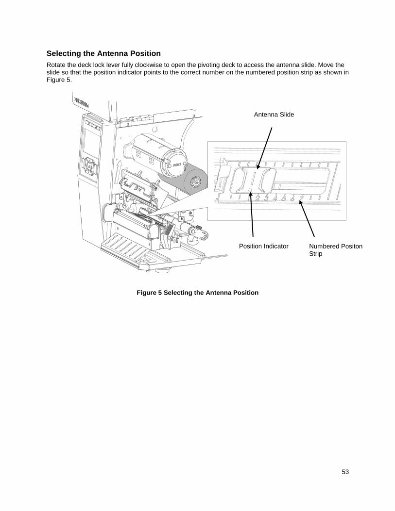
53
Selecting the Antenna Position
Rotate the deck lock lever fully clockwise to open the pivoting deck to access the antenna slide. Move the slide so that the position indicator points to the correct number on the numbered position strip as shown in Figure 5.
Figure 5 Selecting the Antenna Position
Position Indicator Numbered Positon Strip
Antenna Slide

54
RFID Inlay Pitch
This printer specifically encodes inlays for item level applications and supports RFID labels that Printronix defines as Short-Pitch and On-Pitch.
RFID Inlay Pitch
Pitch is defined as the distance from one point on an inlay to the same point on the next inlay. The reference point can be any point on the inlay: leading (or trailing) edge of the antenna (often described as the foil), leading (or trailing) edge of the antenna substrate, or the distance between ICs. Use the RFID Inlay Reference Figure 6 for a clearer understanding of the various points that can be used to determine pitch. The T6 RFID printer supports Short-Pitch and On-Pitch RFID Inlays.
Example: In the RFID menu under Tag Type, if you want to select an Alien 9730 tag you will have a choice of selecting:
Aln9730 ShortPitch or
Aln9730 OnPitch
The correct choice will be based on the difference in pitch described and illustrated in the Short-Pitch and On-Pitch sections below.

55
Short-Pitch RFID Labels
Printronix defines Short-Pitch labels as those with RFID inlays that have a pitch from 1.0 to 2.0 inches. The RFID inlay is short in length, and is constructed into an item level label that permits inlay encoding and provides the required but limited space to print text, graphics, barcodes or logos.
NOTE: Figure 6 shows a section from a roll of Short-Pitch labels and the variety of reference points that can
be used to determine the pitch (in this case one-inch pitch). RFID Inlay Position & Pitch Reference Points
Figure 6 Sample Short-Pitch Label Section
Label
TOF (leading edge of black mark) to the Leading Edge of Foil
= 0.60 Inches
1” Pitch - Leading Edge of One Inlay Foil to the Leading Edge of
the Next Inlay Foil
Inboard Liner to Chip Center = 1.575 Inches
Label Direction
Through Printer
Short-Pitch Label Configuration Using Alien 9730 Squiglette Inlay
Liner
Label Side View
1” Pitch Leading Edge of One Label to the Leading
Edge of the Next Label
1” Pitch - Distance from One IC to the Next IC
Inlay Outline
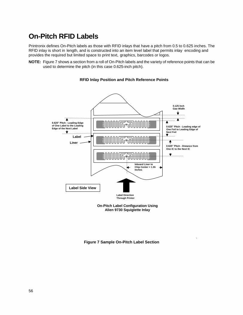
56
On-Pitch RFID Labels
Printronix defines On-Pitch labels as those with RFID inlays that have a pitch from 0.5 to 0.625 inches. The RFID inlay is short in length, and is constructed into an item level label that permits inlay encoding and provides the required but limited space to print text, graphics, barcodes or logos.
NOTE: Figure 7 shows a section from a roll of On-Pitch labels and the variety of reference points that can be
used to determine the pitch (in this case 0.625-inch pitch).
RFID Inlay Position and Pitch Reference Points
Figure 7 Sample On-Pitch Label Section
Label
0.125 Inch Gap Width
0.625” Pitch - Leading edge of One Foil to Leading Edge of Next Foil
Inboard Liner to Chip Center = 1.55 Inches
Label Direction
Through Printer
On-Pitch Label Configuration Using Alien 9730 Squiglette Inlay
Liner
Label Side View
0.625” Pitch - Leading Edge of One Label to the Leading
Edge of the Next Label
0.625” Pitch - Distance from
One IC to the Next IC

57
Setting up the T6 RFID Printer
Media > Media Handling
Continuous. Only forward media motion occurs. When the print job ends the trailing edge of the last label printed remains at the TOF position under the printhead (not aligned at the Tear Bar). If the RFID menu has Control > Tag Position set at a negative value, (ex., -0.2 inches), the printer will move in reverse for a 0.2 inch distance as each tag is encoded. The last label printed will still remain at the TOF position under the printhead (not aligned at the Tear Bar).
Tear-Off Strip. When a print job is sent, the leading edge of the first label will be pulled back to the TOF position under the printhead. If the RFID menu has Tag Position set at a negative value, (ex., -0.2 inches), the printer will move in reverse for a 0.2 inch distance as each tag is encoded. When the print job is complete the printer will place the trailing edge of the last printed label at the tear bar for easy removal.
Sensors > Control
Gap. Select Gap sensing when a liner gap exists between die cut RFID labels.
Mark. Select Mark sensing when a black mark exists on the underside of the RFID label liner.
When the correct sensing is done, perform and Auto-Calibrate.
RFID > Control
RFID Active. Select Enable to enable the RFID encoder module.
Tag Type. Select the Tag Type that matches the inlay used on the desired media. When the proper selection is entered, follow the display panel instructions for setting the antenna slide to the recommended number position (1 thru 7). Refer to Selecting the Antenna Position on page 53.

58
A Errors and Troubleshooting
Error Messages
The RFID encoder can detect a number of errors. When one of these errors occurs, the RFID encoder alerts the printer to perform the currently selected error action (see section Error Handling on page 17) and display the appropriate error message on the control panel’s LCD (see Table 7).
Table 7 RFID Error Messages
Displayed Message Solution/Explanation
RFID Comm Err
Check Cable
RFID error: communication cannot be established between the
printer and the RFID encoder.
1. Press PAUSE to clear the message.
2. Disable the Control > RFID Active menu.
3. See “Troubleshooting” on page 59.
RFID FW ERR:
Version Mismatch
The RFID encoder firmware version is not capable of operating
with the printer software.
1. Press PAUSE to clear the message.
2. Download the program file to the printer again.
RFID LOCK CMD:
Not supported!
A lock command was executed on a tag which does not sup-
port locking. Most Gen 2 tags support locking.
1. Press PAUSE to clear the message.
2. Remove the lock command from the application.
RFID MAX RETRY
Check System The menu Control > Error Handling is set to Overstrike, and the
Label Retry count has been exhausted.
1. Press PAUSE to clear the message.
2. See “Troubleshooting” on page 59.
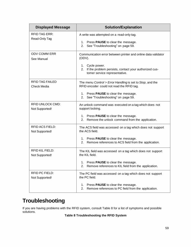
59
Displayed Message Solution/Explanation
RFID TAG ERR:
Read-Only Tag
A write was attempted on a read-only tag.
1. Press PAUSE to clear the message.
2. See “Troubleshooting” on page 59.
ODV COMM ERR
See Manual
Communication error between printer and online data validator
(ODV).
1. Cycle power.
2. If the problem persists, contact your authorized cus-
tomer service representative.
RFID TAG FAILED
Check Media
The menu Control > Error Handling is set to Stop, and the
RFID encoder could not read the RFID tag.
1. Press PAUSE to clear the message.
2. See “Troubleshooting” on page 59.
RFID UNLOCK CMD:
Not Supported!
An unlock command was executed on a tag which does not
support locking.
1. Press PAUSE to clear the message.
2. Remove the unlock command from the application.
RFID ACS FIELD:
Not Supported!
The ACS field was accessed on a tag which does not support
the ACS field.
1. Press PAUSE to clear the message.
2. Remove references to ACS field from the application.
RFID KIL FIELD:
Not Supported!
The KIL field was accessed on a tag which does not support
the KIL field.
1. Press PAUSE to clear the message.
2. Remove references to KIL field from the application.
RFID PC FIELD:
Not Supported!
The PC field was accessed on a tag which does not support
the PC field.
1. Press PAUSE to clear the message.
2. Remove references to PC field from the application.
Troubleshooting
If you are having problems with the RFID system, consult Table 8 for a list of symptoms and possible solutions.
Table 8 Troubleshooting the RFID System

60
Symptom Solution
No communication between the
printer and the RFID encoder 1. Make sure the reader is enabled via Control >
RFID Active menu (page 16).
2. Use the Diagnostics > Read Tag feature
(page 24) to read and display the current RFID
tag content.
3. If the problem persists, your RFID encoder
may be disconnected or defective. Contact
your authorized service representative.
Tag failed 1. The label could be misaligned. Perform the
Sensors > Control > Auto Calibrate procedure
to ensure the label is at top-of-form. For more
information, refer to the Administrator’s
Manual.
2. Make sure the media are smart labels with
RFID tags located in the correct position.
3. The RFID tag could be defective. Try another
tag.
4. Make sure the application does not send too
few or too many digits to the RFID tag.
Inconsistent results Make sure the media is loaded correctly. For more information, refer to the Administrator’s Manual.
The RFID encoder works, but it
does not meet expectations
Make sure that both Control > Error Handling and
Control > Label Retry are set to desired values.
The RFID icon is greyed out in the Settings section:
The printer did not detect the RFID encoder at
power-up. Your RFID encoder may be discon-
nected or defective. Contact your authorized ser-
vice representative.

61
B Contact Information
Printronix Customer Support Center
IMPORTANT Please have the following information available prior to calling the Printronix
Customer Support Center:
• Model number
• Serial number (located on the back of the printer)
• Installed options (i.e., interface and host type if applicable to the problem)
• Configuration printout: Refer to the Administrator’s Manual.
• Is the problem with a new install or an existing printer?
• Description of the problem (be specific)
• Good and bad samples that clearly show the problem (faxing or emailing of
these samples may be required)
Americas (844) 307-7120 [email protected]
Europe, Middle East, and Africa +31 (0) 24 6489 316 [email protected]
Asia Pacific +886 3 990 6155 [email protected]
China +86 755 2398 0479 [email protected]
Printronix Auto ID Support: http://PrintronixAutoID.com/support/
Printronix Auto ID Consumables: http://PrintronixAutoID.com/products/consumables/
62
Corporate Offices
Printronix Auto ID
3040 Saturn Street, Suite
200, Brea, CA 92821
U.S.A.
Phone: (844) 307-7120
Fax: (657) 258-0817
Printronix Auto ID, EMEA Head Office
Georg-Wimmer-Ring 8b D-85604 Zorneding
Germany
Phone: +49 (0) 8106 37979-23
Fax: +49 (0) 8106 37979-05
Printronix Auto ID, Asia Pacific Head Office
Taiwan
9F, No. 95, Minquan Rd. Xindian Dist., New Taipei City 231 Taiwan (R.O.C)
Phone: +886 3 990 6155
Fax: +886 3 990 6215
Printronix Auto ID, China Head Office
Shenzhen
New World Center 2510 room
No. 6009, Yitian road
Futian District, Shenzhen
518000
China
Phone: +86 755 2398 0479
Fax: +86 755 2398 0773
Visit the Printronix web site at www.PrintronixAutoID.com
P220002-001A
Related Documents