Digital Communications and Networks (DCN) journal homepage: www.elsevier.com/locate/dcan RFHUI: An RFID based Human-Unmanned Aerial Vehicle Interaction System in an Indoor Environment Jian Zhang a , Zhitao Yu ab , Xiangyu Wang ab , Yibo Lyu a , Shiwen Mao *b , Senthilkumar CG Periaswamy a , Justin Patton a , Xuyu Wang c a Auburn University RFID Lab, Auburn, AL 36849, USA b Department of Electrical and Computer Engineering, Auburn University, Auburn, AL 36849, USA c Department of Computer Science, California State University, Sacramento, CA 95819-6021, USA Abstract In this paper, we present an RFID based human and unmanned aerial vehicle (UAV) interaction system, termed RFHUI, to provide an intuitive and easy-to-operate method to navigate a UAV in an indoor environment. It relies on the passive radio- frequency identification (RFID) technology to precisely track the pose of a handheld controller, and then transfer the pose information to navigate the UAV. A prototype of the handheld controller is created by attaching three or more Ultra high frequency (UHF) RFID tags to a board. A Commercial Off-The-Shelf (COTS) RFID reader with multiple antennas is deployed to collect the observations of the tags. First, the precise positions of all the tags can be obtained by our proposed method, which leverages a Bayesian filter and channel state information (CSI) phase measurements collected from the RFID reader. Second, we introduce a singular value decomposition (SVD) based approach to obtain a 6-DOF (Degrees of Freedom) pose of the controller from estimated positions of the tags. Furthermore, the pose of the controller can be precisely tracked in a real-time manner, while the user moves the controller. Finally, control commands will be generated from the controller’s pose and sent to the UAV for navigation. The performance of the RFHUI is evaluated by several experiments. The results show that it provides precise poses with 0.045 m mean error in position and 2.5 ◦ mean error in orientation for the controller, and enables the controller to precisely and intuitively navigate the UAV in an indoor environment. c 2018 Published by Elsevier Ltd. KEYWORDS: Radio-frequency identification (RFID); Human Computer Interaction (HCI); Unmanned Aerial Vehicle (UAV); Singular value decomposition (SVD); Localization; Navigation. 1. Introduction The application of Unmanned Aerial Vehicle (UAV), which originated in the military arena, has rapidly expanded to other areas, such as agriculture, research, commerce, and so on. Due to its promi- nent maneuverability, small form factor, and low cost, * Shiwen Mao (Corresponding author) is the Ginn Professor of Department of Electrical and Computer Engineering and Director of Wireless Engineering Research and Education Center, Auburn University, Auburn, AL 36849-5201, USA. Email:[email protected]. 1 This work was presented in part at EAI MobiQui- tous 2018, New York, NY, Nov. 6-8, 2018 [1]. Email: [email protected], [email protected], [email protected], [email protected], [email protected], [email protected], [email protected], [email protected]. the UAV is widely adopted for surveillance, entertain- ment, search and rescue, and inspection for mainte- nance. In terms of personal UAV applications, over the past few years, more and more advanced algorithms and sensors have been introduced, which make their use increasingly powerful and comprehensive. These personal UAVs are usually used for human entertain- ment activities, such as taking photos and videos. The mounting growth of demands makes the interaction between the user and UAV a research topic attracting considerable interests [1]. In this paper, we propose RFID-based Human UAV Interaction (RFHUI), a low-cost, RFID-based system which provides an intuitive and easy-to-operate way to control and navigate a UAV in a complex indoor environment. The proposed method provides a means

Welcome message from author
This document is posted to help you gain knowledge. Please leave a comment to let me know what you think about it! Share it to your friends and learn new things together.
Transcript

Digital Communications and Networks (DCN)
journal homepage: www.elsevier.com/locate/dcan
RFHUI: An RFID based Human-Unmanned Aerial VehicleInteraction System in an Indoor Environment
Jian Zhanga, Zhitao Yuab, Xiangyu Wangab, Yibo Lyua, Shiwen Mao∗b, SenthilkumarCG Periaswamya, Justin Pattona, Xuyu Wangc
aAuburn University RFID Lab, Auburn, AL 36849, USAbDepartment of Electrical and Computer Engineering, Auburn University, Auburn, AL 36849, USAcDepartment of Computer Science, California State University, Sacramento, CA 95819-6021, USA
Abstract
In this paper, we present an RFID based human and unmanned aerial vehicle (UAV) interaction system, termed RFHUI, toprovide an intuitive and easy-to-operate method to navigate a UAV in an indoor environment. It relies on the passive radio-frequency identification (RFID) technology to precisely track the pose of a handheld controller, and then transfer the poseinformation to navigate the UAV. A prototype of the handheld controller is created by attaching three or more Ultra highfrequency (UHF) RFID tags to a board. A Commercial Off-The-Shelf (COTS) RFID reader with multiple antennas is deployedto collect the observations of the tags. First, the precise positions of all the tags can be obtained by our proposed method,which leverages a Bayesian filter and channel state information (CSI) phase measurements collected from the RFID reader.Second, we introduce a singular value decomposition (SVD) based approach to obtain a 6-DOF (Degrees of Freedom) poseof the controller from estimated positions of the tags. Furthermore, the pose of the controller can be precisely tracked in areal-time manner, while the user moves the controller. Finally, control commands will be generated from the controller’s poseand sent to the UAV for navigation. The performance of the RFHUI is evaluated by several experiments. The results show thatit provides precise poses with 0.045 m mean error in position and 2.5◦ mean error in orientation for the controller, and enablesthe controller to precisely and intuitively navigate the UAV in an indoor environment.
c© 2018 Published by Elsevier Ltd.
KEYWORDS: Radio-frequency identification (RFID); Human Computer Interaction (HCI); Unmanned Aerial Vehicle (UAV);Singular value decomposition (SVD); Localization; Navigation.
1. Introduction
The application of Unmanned Aerial Vehicle(UAV), which originated in the military arena, hasrapidly expanded to other areas, such as agriculture,research, commerce, and so on. Due to its promi-nent maneuverability, small form factor, and low cost,
∗Shiwen Mao (Corresponding author) is the Ginn Professor ofDepartment of Electrical and Computer Engineering and Directorof Wireless Engineering Research and Education Center, AuburnUniversity, Auburn, AL 36849-5201, USA. Email:[email protected].
1This work was presented in part at EAI MobiQui-tous 2018, New York, NY, Nov. 6-8, 2018 [1]. Email:[email protected], [email protected],[email protected], [email protected],[email protected], [email protected], [email protected],[email protected].
the UAV is widely adopted for surveillance, entertain-ment, search and rescue, and inspection for mainte-nance. In terms of personal UAV applications, over thepast few years, more and more advanced algorithmsand sensors have been introduced, which make theiruse increasingly powerful and comprehensive. Thesepersonal UAVs are usually used for human entertain-ment activities, such as taking photos and videos. Themounting growth of demands makes the interactionbetween the user and UAV a research topic attractingconsiderable interests [1].
In this paper, we propose RFID-based Human UAVInteraction (RFHUI), a low-cost, RFID-based systemwhich provides an intuitive and easy-to-operate wayto control and navigate a UAV in a complex indoorenvironment. The proposed method provides a means

2 Jian Zhang, et al.
to precisely control a UAV to navigate it in a 3Dspace in a real-time manner. Specifically, we attachN (N ≥ 3) Ultra high frequency (UHF) passive RFIDtags to a small board to create a hand-held controller.We record the position of each tag against the built-incoordinates of the controller. This position is denotedas a local one. We then deploy a Commercial Off-The-Shelf (COTS) RFID reader with multiple antennas togather the observation of the tags. The global position,which refers to the global coordinates in the 3D space,of an RFID tag can be precisely tracked by the chan-nel state information (CSI) phase measurements of theRFID tag responses from multiple antennas. A 6-DoFpose of the controller can be obtained from the knownlocal position and estimated global position of the Nattached tags. Finally, following the movement of thecontroller, the UAV responds and updates its pose andposition in the air. The main contributions of this workcan be summarized as follows:
1. A real-time RFID tag localizer is designed, whichexploits the measured phase information of re-ceived RFID responses at a COTS reader. It lo-calizes multiple UHF RFID tags simultaneously.
2. A real-time pose tracker is proposed. Based onthe position of attached tags, a precise 6-DoFpose for the UAV controller is estimated in a 3Dspace.
3. We transform the pose of the controller into fly-ing control commands for UAV navigation.
4. We implement the RFHUI system with COTSRFID devices and demonstrate its performancein a representative indoor environment. Experi-mental results show that the RFHUI can provideprecise poses with 0.045 m mean error in positionand 2.5◦ mean error in orientation for the con-troller. Thus, it enables the controller to preciselyand intuitively navigate the UAV in an indoor en-vironment.
The remainder of this paper is organized as follows.We review related work in Section 2. We present thedesign and analysis of the RFHUI system in Section 3and our experimental study in Section 4. Section 5concludes this paper.
2. Related Work
With the development of robotics and growing de-mands for civilian and industrial applications, the con-cept of interaction and collaboration between humanand robots has received a lot of attention. The studyof Human Robot Interaction (HRI) focuses on howtheir communication achieves better real-time perfor-mance. It can be approximately divided into three ar-eas of applications: teleoperation in specific environ-ments [2, 3, 4, 5], human-centric social interaction [6],and industrial manufacturing [7]. For applications insocial interaction, Santos et al. proposed a tour-guide
robot which is capable of recognizing users hand ges-tures and providing voice feedback [8]. In the fieldof HRI teleoperation in a specific environment, urbansearch and rescue (USAR) is a high-interest researchtopic for deploying an HRI teleoperation in a specificenvironment. For example, Kohlbrecher et al. pre-sented a human-robot system for rescue missions [9].
Compared to traditional robotic Unmanned GroundVehicles (UGV), the UAV has significant differences,including flying freely, poor carrying capability, andbeing unsafe to touch. These demand a different andsuitable new interaction method for human and UAV.The applications of Human Drone Interaction (HDI)are primarily focused on jogging companion UAVsinvolved in shooting videos, gesture recognition, andfloating display. Muller et al. designed and built anoutside jogging companion quadcopter system withGPS localization [10]. In [11], Scheible et al. pro-posed a system that combines a quadrocopter, a videoprojector, and a mobile phone for projecting contentsonto walls or objects in an open space. Obviously,these UAVs are large and could only be used outdoors,thus prohibiting close interaction between human anddrones. For gesture control applications, Cauchard etal. investigated the problem of multiple participantsand found that natural gesture control leads to a moreintimate relationship between user and UAV [12]. Inthe current commercial UAV market, DJI announced astate-of-the-art small gesture control based UAV prod-uct, called Spark [19], in May 2017. This is the firsttime that gesture recognition technologies have beenintroduced for consumer-class UAVs, enabling the re-moval of a traditional remote controller.
Since the last decade, RFID technology has beenwidely recognized as a promising solution for itemserialization and tracking. Due to its cost-effective,lightweight, small form factor, and power-free proper-ties, the RFID has also been widely deployed for in-door localization [20, 21, 22, 23, 24, 25, 26, 27]. Aconsiderable number of studies have focused on ac-cessing the phase measurement of RF signals for lo-calization [29, 30, 31, 32, 33] and vital sign monitor-ing [34, 35]. Making use of Angle of Arrival (AOA)is a classic solution, which is driven by measuring thephase difference of the signals received at different an-tennas. In [30], Azzouzi presented the new measure-ment results for an AOA approach to localize RFIDtags. In addition to localization applications, RFIDtechnology has also been employed for 3-D recon-struction. Bu et al. proposed an approach based on thephase differences of RF signals for 3-D reconstructionof cubes [36], which is free of the limitation of line-of-sight and battery life constraint. Moreover, thereare many other interesting scenarios that access RFIDtechnology. For example, in [37], the reading pat-terns of RFID tags are leveraged to detect customers’behaviors in a physical clothes store. In [28], RFIDtags are attached to the clothes of a patient to measure

RFHUI: An RFID based Human-Unmanned Aerial Vehicle Interaction System in an Indoor Environment 3
his/her respiration rate.Motivated by the research of the aforementioned
RFID applications, we go beyond the above HRI andHDI works to design a practical HDI navigation sys-tem based on the RFID technology and test it ina real-world laboratory environment. Compared totraditional vision-based HDI systems, the proposedRFHUI does not have the line-of-sight limitation dueto the penetrating characteristics of RF signals.
3. RFHUI Design and Analysis
RFHUI is a low-cost, RFID-based system aiming tooffer flexible human-UAV interaction. It provides anintuitive and easy-to-operate means for controlling aUAV in a 3D space. The RFHUI system comprisesN (N ≥ 3) UHF passive RFID tags and a COST RFIDreader with M (M ≥ 2) antennas. The tags are at-tached to the controller, and, when tracking the RFIDtags by querying the phase information of each tag, a6-DoF pose of the controller can be obtained. Then,the UAV can be controlled by this pose. In this sec-tion, we will introduce the system model and RFHUIarchitecture and design. Table 1 shows the importantnotations used in this paper.
3.1. System Architecture
The system architecture of RFHUI is presented inFig. 1. Our proposed RFHUI system consists of threemain components as follows:
• RFID Localizer: We deploy a Bayesian filter toestimate the global location of the tags by utiliz-ing the phase measurement from each tag, whichis obtained by the reader.
• Pose Tracker: After the global location of N (N ≥3) tags are obtained by the RFID localizer andcombined with the given local location of eachtag, we can track the pose of the controller withan SVD based method. Here, the local location isgiven in the built-in coordinate of the controller.
• Control Module: It converts the pose of the con-troller into flying control commands, which aretransmitted to the UAV. Thus, the UAV can benavigated following a trajectory that is guided bythe movement of the controller.
We present the design of these three components inthe remainder of this section.
3.2. RFID Localizer
In the RFHUI system, phase measurements of thetag responses are collected by an RFID reader with Mantennas. We fix and measure the positions of all theantennas. Hereafter, let lm denote the position of themth antenna in the global coordinate.
Table 1: Important notations used in the paper
Notation Description
N Amount of implemented RFIDtags
M Amount of RFID antennaslm The position of the mth antenna in
the global coordinatext The hypothetical posterior state of
a dynamic system at a given timet. In RFHUI system, it refers tothe position of an RFID tag at timet
ut The received control at time t.In RFHUI system, it denotes thespeed of an RFID tag at time t
zt Observation at time tB(xt) The belief that denotes the proba-
bility of the system is in state x attime t. In RFHUI system, it refersto the probability of a tag in posi-tion xt
P(zt | xt, lm) The observation model of the mthantenna
θ RF phase measured from thereader
R The distance between the readerantenna and an RFID tag
λ Wavelength of the RF radio signalθT , θR, θT AG The RF phase distortion caused by
the reader’s transmit circuits, thereader’s receiver circuits, and thetag’s reflection characteristics, re-spectively
Xc, Yc, Zc Unit vectors of the axes of thebuilt-in coordinates of the con-troller
Xg, Yg, Zg Unit vectors of the axes in theglobal coordinates
Tt, Rt The position and orientation of thecontroller at time t
ptn The position (xt
n, ytn, z
tn)T of the nth
tag at time t in the global coordi-nates
gcTt The rigid transform between the
controller’s built-in coordinatesand the global coordinates at timet
Ht Pose of the controller at time tUt Pose of the UAV at time t
4 Jian Zhang, et al.
RFID Localizer
Based on the phase observations to track
each tag, and output global positions of
the tags.
Pose Tracker
Based on the global positions of tags to
estimate the 6DoF pose of the Controller.
Phase Measurements
Control Model
Based on the pose of the Controller to
navigate the UAV by flying command.
Fig. 1: The system architecture of RFHUI, where the global coordi-nates are built in the real world.
3.2.1. Bayesian Filter Updates for Tag LocalizingIn RFHUI, a Bayesian filter is deployed to localize
the tags mounted on the controller. The Bayesian fil-ter addresses the problem of estimating belief over thehypothetical posterior state x of a dynamic system bysensor observations. For the RFID localizer, the state xdenotes the position of the tag against the global coor-dinate. The beliefB(xt), which denotes the probabilitythat the system is in state x at time t, is recursively up-dated by the Bayesian filter. The update is calculatedfrom control ut, observation zt, and prior beliefB(xt−1)at time (t − 1), which is calculated previously.
Usually, one updating cycle of a typical Bayesianfilter can be divided into two essential steps. Con-trol update or prediction is the first step of the process,which is given as:
B (xt) =
∫P(xt | ut, xt−1)B (xt−1) dxt−1, (1)
where P(xt | ut, xt−1) provides the probability of a tagmoving from position xt−1 to xt under the control ofut, referred to as a motion model, and B(xt) representsthe probability of the tag at position xt after control ut
is executed. We assume that the speed of tags will re-main constant for a very short time interval, and hence,a constant speed model can be deployed for the RFIDlocalizer, which is expressed as:
P(xt | ut, xt−1) (2)
=1√
2πδ
∫ ∆t
0exp
{−
(xt − (xt−1 + ut · y ))2
2δ2
}dy,
where ut denotes the speed of the tag at time t − 1 and∆t represents the time interval between t − 1 and t.
Without loss of generality, we assume the move-ments of the tag satisfy a typical Gaussian distribution
with standard deviation δ. The second step is the mea-surement update, which is written as:
B(xt) = η · B(xt) · P(zt | xt). (3)
In (3), η is a constant to integrate the sum of all B(xt)into 1, and P(zt | xt) represents the observation model.The RFID localizer is equipped with M reader anten-nas. Thus (3) can be rewritten as:
B (xt) =
M∑m=1
η · B(xt) · P(zt | xt, lm), (4)
where P(zt | xt, lm) denotes the observation model forthe mth antenna. It provides the probability when themth antenna in position lm observes measurement zt ofthe tag, which is in position xt. The detail of the modelis presented in the following.
3.2.2. Model of RFID Phase MeasurementThe relationship of the RF phase shift between
transmitted and received signal is given by the follow-ing equation:
θ =
(2π ·
(2Rλ
)+ θT + θR + θT AG
)mod 2π, (5)
where θ is the RF phase measured by the reader, Ris the distance between the reader antenna and theRFID tag, λ is the wavelength of the RF radio sig-nal, θT , θR, θT AG are the RF phase distortion caused bythe reader’s transmit circuits, by the reader’s receivercircuits, and by the tag’s reflection characteristics, re-spectively, and mod is the Modulo operation.
Experiments show that for the same reader antenna,the same RFID tag, and the same radio frequency,θT , θR, and θT AG are fixed, and can be denoted asθ′ = θT + θR + θT AG. Thus (5) can be rewritten as:
θ =
(2π ·
(2Rλ
)+ θ′
)mod 2π. (6)
We assume that a tag is in position xt−1 and a readerantenna in a position lm observes the RF phase θ1 fromthe tag’s response. Under the same RF frequency, thetag moves to position xt and the RF phase θ2 is ob-served from the tag. The differential RF phase mea-surement between the two positions satisfies the fol-lowing conditions:
∆θ12 = (θ1 − θ2) mod 2π (7)
∆θ12 =
2π 2∣∣∣xt−1 · l
gm
∣∣∣λ
+ θ′ mod 2π (8)
−
2π 2∣∣∣xt · l
gm
∣∣∣λ
+ θ′ mod 2π
mod 2π
∆θ12 =
(4πλ· (|xt−1 · lm| − |xt · lm|)
)mod 2π. (9)

RFHUI: An RFID based Human-Unmanned Aerial Vehicle Interaction System in an Indoor Environment 5
Equation (9) shows that under the same frequencyfor the same antenna and the same RFID tag, the dif-ferential RF phase ∆θ12 is only determined by the dis-tance the tag moves from xt−1 to xt. In (9), |xt · lm|denotes the distance between the two positions. Here-after, we assume that all the RF phases are measuredfor the same RFID reader and the same RFID tag un-der the same RF frequency. The tag moves in a dis-crete trajectory that is represented by a series of loca-tions x1, x2, ..., xt. The antenna, which is stationary inposition lm, collects the phase measurement for eachlocation as θ1, θ2, ..., θm. Then, the discrete trajectoryof the movement of the tag should satisfy:
|xi · lm| −∣∣∣x j · lm
∣∣∣ = λ4π ·∆θi j + n · λ2
∆θi j = ( θi − θ j) mod 2πn ∈ {1, 2, 3, ...}i, j ε {1, 2, ..., t} and i , j.
(10)
The observation model P(zt | xt, lm) can be updatedby (10) to provide the probability that if a tag movesfrom xt−1 to xt, the differential RF phase ∆θt,t−1 is ob-tained by the reader. We model the differential RFphase by the following equation:
P(∆θt,t−1 | xt−1, xt, lm) =
{1, if (10) is satisfied0, otherwise.
(11)
Let’s consider the distortion of the RF phase thatis caused by the thermal noise. Experiments revealthat the thermal noises introduces random errors tothe phase measurement following a typical Gaussiandistribution. Thus, we denote the RF phase as θ ∼N(µ, δ), where µ is the RF phase without the distor-tion of thermal noise and δ denotes the standard devi-ation. Hence, we can update the differential RF phaseas ∆θi j ∼ N(µi−µ j,
√2δ), and (11) can be updated as:
P(∆θt,t−1 | xt−1, xt, lm
)=
1√
2πδ
∫ ∆θt,t−1
0exp
−(y −
(µt−µt−1
))2
2δ2
dy (12)
µt−µt−1 =
(2 |xt · lm|
λ−
2 |xt−1 · lm|λ
)mod 2π. (13)
Based on (12), (13) and (4), we can estimate the loca-tions of the RFID tags.
3.3. Pose TrackerThe location of a tag, which is denoted as pt
n =
(xtn, y
tn, z
tn)T for the nth tag at time t, can be estimated
by the RFID localizer. When the controller is locatedat T, with orientation R in the given global coordinate,T and R together are called the pose of the controller.Here, we denote the position of the controller at time tas Tt = (xt, yt, zt)T , and the orientation at time t as
Rt =
Xc · Xg Yc · Xg Zc · Xg
Xc · Yg Yc · Yg Zc · Yg
Xc · Zg Yc · Zg Zc · Zg
, (14)
Fig. 2: The global coordinates versus the built-in coordinates of thecontroller.
where Xc, Yc, and Zc represent the unit vectors of theaxes of the built-in coordinates of the controller, andXg, Yg, and Zg denote the unit vectors of the axes inthe global coordinates. The relationship of the twocoordinates is illustrated in Fig. 2.
We measure the location of each attached tag in thecontroller’s built-in coordinates, and the local locationfor the nth tag is denoted as pn = (xn, yn, zn)T . Thetransformation between the global location and locallocation of the same tag is given by:
Ptn =
gcTt · Pn
Ptn = (pt
n, 1)T
Pn = (pn, 1)T ,(15)
where gcTt denotes the rigid transform at time t, pt
n andpn is the location of the nth tag in the global coordi-nates and the controller’s built-in coordinates, respec-tively. In (15), g
cTt comprises the pose of the controllerin the global coordinate:
gcTt =
[Rt Tt
0 0 0 1
], (16)
where Rt and Tt denote the global orientation andglobal position of the controller at time t, respectively.Based on (15) and (16), we can obtain the pose of con-troller by searching an optimal transform g
cTt. Whenthe global locations of all the tags of the controller areprovided by proposed RFID localizer, (15) can be up-dated as follows:
pt1 = Rt · p1 + Tt
pt2 = Rt · p2 + Tt
...pt
n = Rt · pn + Tt,
(17)
where pt1, pt
2, and ptn are the global locations for tag 1,
2, and n, respectively; and p1, p2, and pn are the locallocations for tag 1, 2, and n, respectively. Therefore,the process of finding an optimal transform g
cTt can be

6 Jian Zhang, et al.
formulated as a least square minimization problem as:
min{Rt ,Tt}
N∑i=1
‖ pti − (Rt · pi + Tt) ‖, (18)
where N is the total number of tags and || · || is the normof a vector. Problem (18) is a typical problem of de-termining the rotation and translation relationship be-tween two sets of data points at different coordinates,and a variety of methods have been introduced to solvesuch problems [39, 40]. Based on the approach that isintroduced in [39], our proposed pose tracker is devel-oped to find the optimal g
cTt in three steps:Step 1 . Finding the centroids of all the locations in
both the global coordinates and the local coordinates,which is denoted as C and C, respectively. Then, usethe centroids as the new origins of two coordinates andtransfer the locations into these two coordinates, as:{
pti′
= pti − C, for i ∈ [1, 2, ...,N]
p′i = pi − C, for i ∈ [1, 2, ...,N], (19)
where N is the total number of tags.Step 2 . Determining the optimal rotation Rt with the
singular value decomposition (SVD) method. First,cascade all the shifted locations of the tags in bothglobal and local coordinates to form two matrices:{
A = [pt1′,pt
2′, ...,pt
n′]
B = [p′1, p′2, ..., p
′n], (20)
where both A and B are 3 × N matrices. Then, wedecompose or factorize the matrix ABT with the SVDmethod as:
[U,D,V] = SVD(ABT ), (21)
where, UUT = VVT = 1, and D = diag(di), d1 ≥ d2 ≥
· · · ≥ dn ≥ 0. Based on the result in [39], we obtainthe optimal rotation Rt as:
Rt = USVT , (22)
where
S =
{I, if det(U) det(V) = 1diag(1, 1, ..., 1,−1), if det(U) det(V) = −1.
(23)
In (23), I is an identity matrix, and diag(·) is a diagonalmatrix.Step 3 . Obtaining the translation Tt. After obtaining
the rotation Rt, Tt can be determined by the followingequation:
Tt = C − Rt · C. (24)
Therefore, based on the locations of the tags inboth global and local coordinates, the proposed posetracker can determine the controller’s pose, includingthe orientation Rt and the position Tt, referring to theglobal coordinates.
3.4. Human UAV Interaction Module
The human UAV interaction module primarily linksthe change of the controller’s pose with UAV move-ment to achieve flexible remote control. We use theestimated pose of the controller to control the navi-gation of the UAV. To achieve real-time control, theUAV must react sensitively to the change of the con-troller’s pose in a manner that follows the trajectory ofthe moving controller.
We use Ht to denote the pose of the controller, andUt to denote the pose of the UAV at time t. The processof the module can be divided into four steps, which aredetailed as follows:
1. Obtaining Ht and Ht+1 from the pose tracker.
2. Calculating ∆H = Ht+1 − Ht, which contains thechange of position and orientation in the three-dimensional space.
3. Amplifying ∆H as ∆H′ = α · ∆H, where α is theparameter of the amplification, and we usually setα = 5. We can make a slight movement of thecontroller to activate a large-scale movement ofthe UAV.
4. Converting the ∆H′ to flying control commandsand send it to the UAV.
Step 4 cooperates with the specific UAV platform, andit usually relies on the API to communicate with theUAV. For example, in our experimental platform, anROS [38] based system is developed to communicatewith the ARDrone2.0 platform [13]. It updates the tar-get position of the UAV by
Ut+1 = Ut + ∆H′, (25)
and sends the Ut+1 to the UAV through the ROS mes-sage service.
4. Experimental Validation and Results
4.1. Experiment Setup
We conduct a series of experiments to demonstratethe performance of the RFHUI system. We establisha prototype of RFHUI using a COTS reader and sev-eral UHF passive RFID tags. A Zebra FX7500 RFIDreader [14] with four Zebra AN720 antennas [15] is in-corporated to query the RFID tags. The Zebra FX7500reader is widely deployed in retail, manufacture fac-tory, and warehouse applications, and meets the EPCGen2 standard requirements [16].
In our prototype system, we use the Low-LevelReader Protocol (LLRP) through an Ethernet port tocommunicate with the reader and report the RFIDmeasurements. The Zebra AN720 Antennas provide aleft circular polarization with a 100◦ beam width anda 5.5 ∼ 6 dB gain. Each antenna is mounted on aholder of 1.4 m height. The four antennas with their

RFHUI: An RFID based Human-Unmanned Aerial Vehicle Interaction System in an Indoor Environment 7
Fig. 3: Side view of the RFID detectable field.
Fig. 4: Top view of the RFID detectable field.
holders are deployed in front of the user. In all ourexperiments, we set the reader works at the maximumRF transmission power, i.e., 33 dBm, to enable eachantenna to gain a detectable range up to 6 m. Our ex-perimental setting is illustrated in Fig. 3 (side view)and Fig. 4 (top view). The configuration of the fourantennas created a detectable field, which allows thefour antennas to interrogate an RFID tag simultane-ously.
Three UHF passive RFID tags are attached to afoam board working as our prototype controller, whichis shown in Fig. 5. Fig. 6 shows how the controller isoperated by a user during the tests. Our experimen-tal RFID tag is Smartrac Dogbone Monza R6 [17],which is widely used in the retail business. We chooseThe Parrot ARDrone2.0 Elite Edition drone [18] asour UAV platform, which is shown in Fig. 7. It isequipped with a front camera, a bottom camera, asonar, and an inertial measurement unit (IMU). Basedon the measurements of the onboard sensors, it canlocalize itself by using a sensor fusion method. Forexample, the Parallel Tracking and Mapping (PTAM)technique [19] can be implemented to estimate the 3Dpose of the ARDrone2.0 drone.
Fig. 5: A prototype of our RFHUI controller.
Fig. 6: A user holds the controller in hand during an experiment.
Fig. 7: The ARDrone2.0 Elite Edition drone used in our experi-ments.
4.2. Accuracy of RFID tracking and Pose Estimation
4.2.1. Effect of the Number of AntennasBefore revealing the performance of the proposed
RFHUI system, we first conduct a set of benchmarkexperiments to discover the effect of the number ofRFID antennas on the system performance. We con-

8 Jian Zhang, et al.
0.8
0.9
1
1.1
0.8
0.9
1
1.1
0
0.5
1
X−axisY−axis
Z−
axis
Fig. 8: The moving trajectory of the benchmark experiments: thered points are the sampled locations.
4 antennas 3 antennas 2 antennas 1 antenna0
0.2
0.4
0.6
0.8
1
Avg D
ista
nce
Err
or(
m)
Tag1
Tag2
Tag3
Fig. 9: The average error and standard deviation of the localizationerror of the controller’s tags for different antenna configurations.
figure the RFID reader with 1, 2, 3, and 4 antennasin each benchmark experiment, respectively. Duringevery benchmark experiment, the controller is movedalong the same trajectory, which is given in Fig. 8. Wefirst moved the controller with 20 centimeters in thedirection of the x-axis, and then moved it for another20 centimeters along the y-axis direction. We sam-pled the trajectory every 2 centimeters, which is illus-trated by the red points in Fig. 8. There were totally 21sampled points. At every sampled point we record theground truth location and the estimated location thatis provided by the RFID localizer for every tag andcollect the ground truth and the estimated pose of thecontroller.
First, we evaluate the accuracy of the RFID local-izer by comparing the estimated location to the groundtruth location of every tag at all sample points. Theaverage location error of each tag at different antennaconfigurations is shown in Fig. 9. We can see that themore antennas are deployed, the more accurate the es-timated localization. The results are consistent withthe conclusion of (4): the more antennas are deployed,the more accurate estimation can be made.
We also evaluate the accuracy of the controller’spose, including position and orientation, which ismeasured by our RFHUI system. The results ineach antenna configuration are given in Fig. 10 andFig. 11. From Fig. 10 and Fig. 11, the average er-
4 antennas 3 antennas 2 antennas 1 antennas0
0.1
0.2
0.3
0.4
0.5
0.6
Posi
tion E
rror(
mete
r)
Fig. 10: The average position error of the controller for differentantenna configurations.
4 antennas 3 antennas 2 antennas 1 antennas0
5
10
15
20
25
30
35
Ori
en
tati
on
Err
or(
rad
)
Fig. 11: The average orientation error of the controller for differentantenna configurations.
rors of both position and orientation are reduced dra-matically when the number of deployed antennas isincreased. For the configuration with 4 antennas, thesystem achieves an average error of 0.021 m in posi-tion and 1.8◦ in orientation. Therefore, all hereafterexperiments are executed with the 4-antenna configu-ration with the setup shown in Fig. 4.
4.2.2. RFID Tags TrackingTo evaluate the performance of the RFID localizer
in RFHUI, we launch another experiment by attach-ing three UHF passive RFID tags to the controller.A user holds the controller and moves it following agiven trajectory, which is inside the experiment field.In contrast to the simple trajectory in our benchmarkexperiments, we move the controller in a more com-plex and longer trajectory with more variety in movingdirection, thus to mimic the actual user behavior whileoperating the UAV. During the experiment, the RFIDlocalizer of RFHUI provides estimated locations foreach tag while the controller is moving. We obtainthe ground-truth locations by measuring the sampledpoints every 5 mm along the trajectory. The accuracyof the proposed method is evaluated by calculating theerrors between the ground-truth locations and the esti-mated locations of the sampled points.
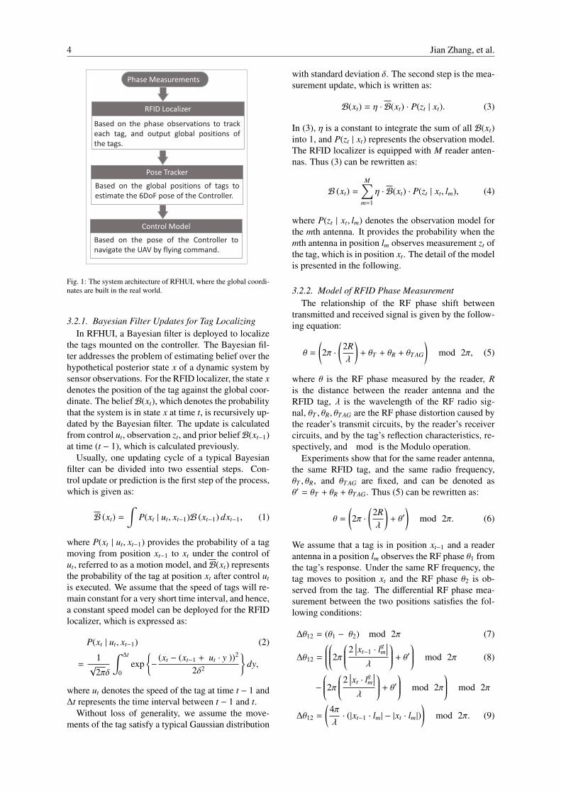
We repeat the experiment several times, and the ex-perimental results are presented in Fig. 12 in the formof the cumulative distribution function (CDF) of lo-calization errors between estimated and ground-truth
RFHUI: An RFID based Human-Unmanned Aerial Vehicle Interaction System in an Indoor Environment 9
0 0.01 0.02 0.03 0.04 0.05 0.06 0.07 0.08 0.09 0.1
Localization Error (m)
0
0.2
0.4
0.6
0.8
1C
DF
RFHUI Tag0
RFHUI Tag1
RFHUI Tag2
Fig. 12: CDF of RFID tags tracking error with a more complex andlonger trajectory.
positions. We can see that the maximum error of theRFID localizer is less than 0.095 m for all the threetags. Moreover, with the RFID localizer of RFHUI,80% of the localization errors are less than 0.045 mand 90% of them are under 0.06 m. Therefore, it issafe to state that the RFID localizer achieves very pre-cise localization for tracking the moving RFID tags.Note that the average error of every tag is a little bithigher than that in the benchmark experiments be-cause we considered much more sample points and thecontroller moves along a more complex trajectory inthis experiment.
4.2.3. Controller Pose EstimationWe next conduct an experiment to verify the fea-
sibility and accuracy of our proposed pose tracker,including position and orientation estimation. Thecontroller moves along a trajectory in our experimentfield, held by a user.
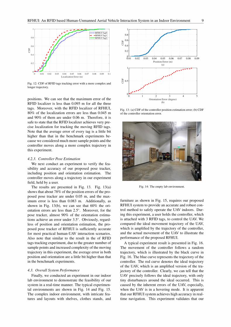
The results are presented in Fig. 13. Fig. 13(a)shows that about 78% of the position errors of the pro-posed pose tracker are under 0.05 m, and the max-imum error is less than 0.083 m. Additionally, asshown in Fig. 13(b), we can see that 60% the ori-entation errors are less than 2.5◦. Moreover, for thepose tracker, almost 90% of the orientation estima-tions achieve an error under 3.5◦. Obviously, regard-less of position and orientation estimation, the pro-posed pose tracker of RFHUI is sufficiently accuratefor most practical human-UAV interaction scenarios.Also note that similar to the result in the of RFIDtags tracking experiment, due to the greater number ofsample points and increased complexity of the movingtrajectory in this experiment, the average error in bothposition and orientation are a little bit higher than thatin the benchmark experiments.
4.3. Overall System PerformanceFinally, we conducted an experiment in our indoor
lab environment to demonstrate the feasibility of oursystem in a real-time manner. The typical experimen-tal environments are shown in Fig. 14 and Fig. 15.The complex indoor environment, with intricate fea-tures and layouts with shelves, clothes stands, and
0.01 0.02 0.03 0.04 0.05 0.06 0.07 0.08 0.090
0.2
0.4
0.6
0.8
1
Position Error (m)(a)
CD
F
0 1 2 3 4 50
0.5
1
Orientation Error (degree)(b)
CD
F
Fig. 13: (a) CDF of the controller position estimation error; (b) CDFof the controller orientation error.
Fig. 14: The empty lab environment.
furniture as shown in Fig. 15, requires our proposedRFHUI system to provide an accurate and robust con-trol method to safely operate the UAV indoors. Dur-ing this experiment, a user holds the controller, whichis attached with 3 RFID tags, to control the UAV. Wecompared the ideal movement trajectory of the UAV,which is amplified by the trajectory of the controller,and the actual movement of the UAV to illustrate theperformance of the proposed RFHUI.
A typical experiment result is presented in Fig. 16.The movement of the controller follows a randomtrajectory, which is illustrated by the black curve inFig. 16. The blue curve represents the trajectory of thecontroller. The red curve denotes the ideal trajectoryof the UAV, which is an amplified version of the tra-jectory of the controller. Clearly, we can tell that theUAV precisely follows the ideal trajectory, with onlytiny disturbances around the ideal occurred. This iscaused by the inherent errors of the UAV, especially,when the UAV is in a hovering mode. It is apparentthat our RFHUI system achieves high accuracy in real-time navigation. This experiment validates that our

10 Jian Zhang, et al.
Fig. 15: The cluttered lab environment.
0.5
1
1
Z-a
xis
1.5
0.5
Y-axis0
X-axis
10.80.60.40.20
Controller trajectory
UAV ideal Trajectory
UAV real-time Trajectory
Fig. 16: Trajectory comparison
RFID-based controller strategy is robust and practical.This is mainly due to the fact that our proposed RFHUIsystem can provide a highly accurate pose estimation,which plays a critical role in UAV navigation.
5. Conclusions
In this paper, we proposed the RFHUI, an RFIDbased system for navigation control of a UAV us-ing a COTS RFID reader. We experimentally vali-dated the feasibility of utilizing an RFID localization-based method as the core of the UAV controller. Weleveraged a Bayesian filter to estimate the location ofRFID tags using the phase information in RFID tagresponses. Then an SVD algorithm was employed fordata pre-processing to track the pose of the controller.Finally, the control module converted the pose datainto flying control commands to achieve UAV naviga-tion control in real-time. The extensive experiments ina representative lab environment demonstrated the ca-pability of the proposed RFHUI system. To the best ofour knowledge, the proposed RFHUI is the first practi-cable UHF passive RFID based UAV navigation con-trol system, which provides a promising method forHuman-UAV interaction.
Acknowledgements
This work is supported in part by the US NSF underGrant CNS-1702957, and by the Wireless EngineeringResearch and Education Center (WEREC) at AuburnUniversity.
References
[1] J. Zhang, Z. Yu, X. Wang, Y. Lyu, S. Mao, S.C.G. Periaswamy,J. Patton, and X. Wang, “RFHUI: An intuitive and easy-to-operate human-UAV interaction system for controlling a UAVin a 3D space,” in Proc. EAI MobiQuitous 2018, New YorkCity, NY, Nov. 2018, pp.1–8.
[2] J. L. Casper and R. R. Murphy, “Workflow study on human-robot interaction in USAR,” in Proc. 2002 IEEE InternationalConference on Robotics and Automation, Washington, DC,May 2002, pp.1997–2003.
[3] H. Jones, S. Rock, D. Burns, and S. Morris, “Autonomousrobots in swat applications: Research, design, and operationschallenges,” in Proc. 2002 Symposium for the Association ofUnmanned Vehicle Systems International (AUVSI ’02), Or-lando, FL, July 2002, pp.1–15.
[4] M. Li, K. Lu, H. Zhu, M. Chen, S. Mao, and B. Prabhakaran,“Robot swarm communication networks: Architectures, pro-tocols, and applications,” in Proc. Chinacom’08, Hangzhou,P.R. China, Aug. 2008, pp.162–166.
[5] M. Li, J. Harris, M. Chen, S. Mao, Y. Xiao, W. Read, andB. Prabhakaran, “Architecture and protocol design for a per-vasive robot swarm communication networks,” Wiley WirelessCommunications and Mobile Computing Journal (WCMC),vol.11, no.8, pp.1092–1106, Aug. 2011.
[6] C. Bartneck and J. Forlizzi, “A design-centered frameworkfor social human-robot interaction,” in Proc. InternationalWorkshop on Robot and Human Interactive Communication,Kurashiki, Japan, Sept. 2004, pp.591–594.
[7] O. O. Ogorodnikova “Safe and reliable human-robot inter-action in manufactory, within and beyond the workcell,” inProc. 19th International Workshop on Robotics in Alpe-Adria-Danube Region, Budapest, Hungary, June 2010, pp.65–70.
[8] V. Alvarez-Santos, R. Iglesias, X. M. Pardo, C. V. Regueiro,and A. Canedo-Rodriguez, “Gesture-based interaction withvoice feedback for a tour-guide robot,” Journal of Visual Com-munication and Image Representation, vol.25, no.2, pp.499–509, Feb. 2014.
[9] S. Kohlbrecher, A. Romay, A. Stumpf, A. Gupta, O. vonStryk, F. Bacim, D. A. Bowman, A. Goins, R. Balasubra-manian, and D. C. Conner, “Human-robot teaming for res-cue missions: Team ViGIR’s approach to the 2013 DARPARobotics Challenge trials,” Journal of Field Robotics, vol.32,no.3, pp.245–267, May 2015.
[10] F. Mueller and M. Muirhead, “Jogging with a quadcopter,”in Proc. 33rd Annual ACM Conference on Human Factorsin Computing Systems, Seoul, Republic of Korea, Apr. 2015,pp.2023–2032.
[11] J. Scheible, A. Hoth, J. Saal, and H. Su, “Displaydrone: A fly-ing robot based interactive display,” in Proc. 2nd ACM Inter-national Symposium on Pervasive Displays, Mountain View,CA, June 2013, pp.49–54.
[12] J. R. Cauchard, J. L. E. Kevin, Y. Zhai, and J. A. Landay,“Drone & me: An exploration into natural human-drone in-teraction,” in Proc. UbiComp’15, Osaka, Japan, Sept. 2015,pp.361–365.
[13] Parrot ARDrone2.0, [online] Available:https://www.parrot.com/global/drones/
parrot-ardrone-20-elite-edition#
parrot-ardrone-20-elite-edition. Accessed onJune. 4, 2018.
[14] Zebra, fx7500, [online] Available: https://www.zebra.
com/us/en/products/rfid/rfid-readers/fx7500.
html. Access on June. 4, 2018.

RFHUI: An RFID based Human-Unmanned Aerial Vehicle Interaction System in an Indoor Environment 11
[15] Zebra, an720, [online] Available: https://www.zebra.
com/us/en/products/rfid/rfid-reader-antennas/
an720.html. Accessed on June. 4, 2018.[16] GS1 US, [online] Available: https://www.gs1us.org/.
Accessed on June. 4, 2018.[17] Samrtarc, Dogbone, [online] Available: https://www.
smartrac\-group.com/files/content/Products\
_Services/PDF/0028\_SMARTRAC\_DOGBONE.pdf.Accessed on June. 4, 2018.
[18] G. Klein and D. Murray, “Parallel tracking and mapping forsmall AR workspaces,” in Proc. 6th IEEE and ACM Inter-national Symposium on Mixed and Augmented Reality, Nara,Japan, Nov. 2007, pp.225–234.
[19] DJI, SPARK, [online] Available: https://www.dji.com/
spark. Accessed on June. 4, 2018.[20] F. Gandino, B. Montrucchio, M. Rebaudengo, and E. R.
Sanchez, “On improving automation by integrating RFID inthe traceability management of the agri-food sector,” IEEETransactions on Industrial Electronics, vol.56, no.7, pp.2357–2365, July 2009.
[21] L. Jing and P. Yang, “A localization algorithm for mobilerobots in RFID system,” in Proc. 2007 International Confer-ence on Wireless Communications, Networking and MobileComputing, Wuhan, China, Sept. 2007, pp.2109–2112.
[22] P. Yang, W. Wu, M. Moniri, and C. C. Chibelushi, “SLAM al-gorithm for 2D object trajectory tracking based on RFID pas-sive tags,” in Proc. IEEE RFID 2008, Las Vegas, NV, Apr.2008, pp.165–172.
[23] A. Bekkali, H. Sanson, and M. Matsumoto, “RFID indoorpositioning based on probabilistic RFID map and KalmanFiltering,” in Proc. Third IEEE International Conference onWireless and Mobile Computing, Networking and Communi-cations, White Plains, NY, Oct. 2007, pp.21–21.
[24] P. V. Nikitin, R. Martinez, S. Ramamurthy, H. Leland, G.Spiess, and K. V. S. Rao, “Phase based spatial identificationof UHF RFID tags,” in Proc. IEEE RFID’10, Orlando, FL,Apr. 2010, pp.102–109.
[25] J. Zhang, Y. Lyu, J. Patton, S. Chinnappa Gounder P, and T.Roppel, “BFVP: A probabilistic UHF RFID tag localizationalgorithm using Bayesian filter and a variable power RFIDmodel,” IEEE Transactions on Industrial Electronics, vol.65,no.10, pp.8250–8259, Oct. 2018.
[26] T. M. Choi, “Coordination and risk analysis of VMI supplychains with RFID technology,” IEEE Trans. Ind. Informat.,vol.7, no.3, pp.497–504, Aug. 2011.
[27] X. Wang, C. Yang, and S. Mao, “SparseTag: High-precisionbackscatter indoor localization using sparse RFID tags ar-ray,” preprint, in Proc. IEEE SECON 2019, Boston, MA, June2019, pp.1–9.
[28] C. Yang, X. Wang, and S. Mao, “AutoTag: Recurrent vi-brational autoencoder for unsupervised apnea detection withRFID tags,” in Proc. IEEE GLOBECOM 2018, Abu Dhabi,United Arab Emirates, Dec. 2018, pp.1–6.
[29] Y. Zou, “Survivable RFID systems: Issues, challenges, andtechniques,” IEEE Transactions on Systems, Man, and Cy-bernetics, Part C (Applications and Reviews), vol.40, no.4,pp.406–418, July 2010.
[30] S. Azzouzi, M. Cremer, U. Dettmar, R. Kronberger, andT. Knie, “New measurement results for the localization ofUHF RFID transponders using an Angle of Arrival (AoA) ap-proach,” in Proc. IEEE RFID’11, Orlando, CA, Apr. 2011,pp.91–97.
[31] X. Wang, L. Gao, and S. Mao, “CSI Phase Fingerprinting forIndoor Localization with a Deep Learning Approach,” IEEEInternet of Things Journal, vol.3, no.6, pp.1113–1123, Dec.2016.
[32] X. Wang, L. Gao, and S. Mao, “PhaseFi: Phase fingerprint-ing for indoor localization with a deep learning approach,” inProc. IEEE GLOBECOM 2015, San Diego, CA, Dec. 2015,pp.1–6.
[33] X. Wang, L. Gao, and S. Mao, “BiLoc: Bi-modality deeplearning for indoor localization with 5GHz commodity Wi-Fi,” IEEE Access Journal, vol.5, no.1, pp.4209–4220, Mar.
2017.[34] X. Wang, R. Huang, and S. Mao, “SonarBeat: Sonar phase for
breathing beat monitoring with smartphones,” in Proc. ICCCN2017, Vancouver, Canada, July/Aug. 2017, pp.1–8.
[35] X. Wang, C. Yang, and S. Mao, “PhaseBeat: Exploiting CSIphase data for vital sign monitoring with commodity WiFi de-vices,” in Proc. IEEE ICDCS 2017, Atlanta, GA, June 2017,pp.1230–1239.
[36] Y. Bu, L. Xie, J. Liu, B. He, Y. Gong, and S. Lu, “3-dimensional reconstruction on tagged packages via RFID sys-tems,” in Proc. IEEE SECON’17, San Diego, CA, June 2017,pp.1–9.
[37] Z. Zhou, L. Shangguan, X. Zheng, L. Yang, and Y. Liu, “De-sign and implementation of an RFID-based customer shop-ping behavior mining system,” IEEE/ACM Transactions onNetworking, vol.25, no.4, pp.2405–2418, Aug. 2017.
[38] ROS, [online] Available: http://www.ros.org/. Accessedon June. 4, 2018.
[39] S. Umeyama, “Least-squares estimation of transformation pa-rameters between two point patterns,” Transactions on PatternAnalysis & Machine Intelligence, vol.13, no.4, pp.376–380,Apr. 1991.
[40] D.W. Eggert, A. Lorusso, and R. B. Fisher, “Estimating 3-D rigid body transformations: A comparison of four majoralgorithms,” Mach. Vis. Appl., vol.9, no.5/6, pp.272–290, Mar.1997.
Related Documents