BioMed Central Page 1 of 9 (page number not for citation purposes) BioMedical Engineering OnLine Open Access Research RF tumor ablation with internally cooled electrodes and saline infusion: what is the optimal location of the saline infusion? Fernando Burdío 1 , Enrique J Berjano* 2 , Ana Navarro 3 , José M Burdío 4 , Antonio Güemes 3 , Luis Grande 1 , Ramón Sousa 3 , Jorge Subiró 5 , Ana Gonzalez 6 , Ignacio Cruz 6 , Tomás Castiella 7 , Eloy Tejero 3 , Ricardo Lozano 3 and Miguel A de Gregorio 8 Address: 1 Department of Surgery, Hospital del Mar, Barcelona, Spain, 2 Center for Research and Innovation on Bioengineering, Valencia Polytechnic University, Valencia, Spain, 3 Department of Surgery A, Hospital Clínico Universitario Lozano Blesa, Zaragoza, Spain, 4 Department of Electric Engineering and Communications, University of Zaragoza, Spain, 5 Department of Urology, Hospital Clínico Universitario Lozano Blesa, Zaragoza, Spain, 6 Department of Animal Pathology and Surgery, Veterinary Faculty, University of Zaragoza, Spain, 7 Department of Pathology, Hospital Clínico Universitario Lozano Blesa, Zaragoza and 8 Department of Radiology, Hospital Clínico Universitario Lozano Blesa, Zaragoza, Spain Email: Fernando Burdío - [email protected]; Enrique J Berjano* - [email protected]; Ana Navarro - [email protected]; José M Burdío - [email protected]; Antonio Güemes - [email protected]; Luis Grande - [email protected]; Ramón Sousa - [email protected]; Jorge Subiró - [email protected]; Ana Gonzalez - [email protected]; Ignacio Cruz - [email protected]; Tomás Castiella - [email protected]; Eloy Tejero - [email protected]; Ricardo Lozano - [email protected]; Miguel A de Gregorio - [email protected] * Corresponding author Abstract Background: Radiofrequency ablation (RFA) of tumors by means of internally cooled electrodes (ICE) combined with interstitial infusion of saline may improve clinical results. To date, infusion has been conducted through outlets placed on the surface of the cooled electrode. However, the effect of infusion at a distance from the electrode surface is unknown. Our aim was to assess the effect of perfusion distance (PD) on the coagulation geometry and deposited power during RFA using ICE. Methods: Experiments were performed on excised bovine livers. Perfusion distance (PD) was defined as the shortest distance between the infusion outlet and the surface of the ICE. We considered three values of PD: 0, 2 and 4 mm. Two sets of experiments were considered: 1) 15 ablations of 10 minutes (n ≥ 4 for each PD), in order to evaluate the effect of PD on volume and diameters of coagulation; and 2) 20 additional ablations of 20 minutes. The effect of PD on deposited power and relative frequency of uncontrolled impedance rises (roll-off) was evaluated using the results from the two sets of experiments (n ≥ 7 for each PD). Comparisons between PD were performed by analysis of variance or Kruskal-Wallis test. Additionally, non-linear regression models were performed to elucidate the best PD in terms of coagulation volume and diameter, and the occurrence of uncontrolled impedance rises. Results: The best-fit least square functions were always obtained with quadratic curves where volume and diameters of coagulation were maximum for a PD of 2 mm. A thirty per cent increase in volume coagulation was observed for this PD value compared to other values (P < 0.05). Likewise, the short coagulation diameter was nearly twenty five per cent larger for a 2 mm PD than for 0 mm. Regarding deposited power, the best-fit least square function was obtained by a quadratic curve with a 2 mm PD peak. This matched well with the higher relative frequency of uncontrolled impedance rises for PD of 0 and 4 mm. Published: 16 July 2007 BioMedical Engineering OnLine 2007, 6:30 doi:10.1186/1475-925X-6-30 Received: 19 March 2007 Accepted: 16 July 2007 This article is available from: http://www.biomedical-engineering-online.com/content/6/1/30 © 2007 Burdío et al; licensee BioMed Central Ltd. This is an Open Access article distributed under the terms of the Creative Commons Attribution License (http://creativecommons.org/licenses/by/2.0 ), which permits unrestricted use, distribution, and reproduction in any medium, provided the original work is properly cited.

Welcome message from author
This document is posted to help you gain knowledge. Please leave a comment to let me know what you think about it! Share it to your friends and learn new things together.
Transcript
BioMed CentralBioMedical Engineering OnLine
ss
Open AcceResearchRF tumor ablation with internally cooled electrodes and saline infusion: what is the optimal location of the saline infusion?Fernando Burdío1, Enrique J Berjano*2, Ana Navarro3, José M Burdío4, Antonio Güemes3, Luis Grande1, Ramón Sousa3, Jorge Subiró5, Ana Gonzalez6, Ignacio Cruz6, Tomás Castiella7, Eloy Tejero3, Ricardo Lozano3 and Miguel A de Gregorio8Address: 1Department of Surgery, Hospital del Mar, Barcelona, Spain, 2Center for Research and Innovation on Bioengineering, Valencia Polytechnic University, Valencia, Spain, 3Department of Surgery A, Hospital Clínico Universitario Lozano Blesa, Zaragoza, Spain, 4Department of Electric Engineering and Communications, University of Zaragoza, Spain, 5Department of Urology, Hospital Clínico Universitario Lozano Blesa, Zaragoza, Spain, 6Department of Animal Pathology and Surgery, Veterinary Faculty, University of Zaragoza, Spain, 7Department of Pathology, Hospital Clínico Universitario Lozano Blesa, Zaragoza and 8Department of Radiology, Hospital Clínico Universitario Lozano Blesa, Zaragoza, Spain
Email: Fernando Burdío - [email protected]; Enrique J Berjano* - [email protected]; Ana Navarro - [email protected]; José M Burdío - [email protected]; Antonio Güemes - [email protected]; Luis Grande - [email protected]; Ramón Sousa - [email protected]; Jorge Subiró - [email protected]; Ana Gonzalez - [email protected]; Ignacio Cruz - [email protected]; Tomás Castiella - [email protected]; Eloy Tejero - [email protected]; Ricardo Lozano - [email protected]; Miguel A de Gregorio - [email protected]
* Corresponding author
AbstractBackground: Radiofrequency ablation (RFA) of tumors by means of internally cooled electrodes (ICE) combined withinterstitial infusion of saline may improve clinical results. To date, infusion has been conducted through outlets placed onthe surface of the cooled electrode. However, the effect of infusion at a distance from the electrode surface is unknown.Our aim was to assess the effect of perfusion distance (PD) on the coagulation geometry and deposited power duringRFA using ICE.
Methods: Experiments were performed on excised bovine livers. Perfusion distance (PD) was defined as the shortestdistance between the infusion outlet and the surface of the ICE. We considered three values of PD: 0, 2 and 4 mm. Twosets of experiments were considered: 1) 15 ablations of 10 minutes (n ≥ 4 for each PD), in order to evaluate the effectof PD on volume and diameters of coagulation; and 2) 20 additional ablations of 20 minutes. The effect of PD ondeposited power and relative frequency of uncontrolled impedance rises (roll-off) was evaluated using the results fromthe two sets of experiments (n ≥ 7 for each PD). Comparisons between PD were performed by analysis of variance orKruskal-Wallis test. Additionally, non-linear regression models were performed to elucidate the best PD in terms ofcoagulation volume and diameter, and the occurrence of uncontrolled impedance rises.
Results: The best-fit least square functions were always obtained with quadratic curves where volume and diameters ofcoagulation were maximum for a PD of 2 mm. A thirty per cent increase in volume coagulation was observed for thisPD value compared to other values (P < 0.05). Likewise, the short coagulation diameter was nearly twenty five per centlarger for a 2 mm PD than for 0 mm. Regarding deposited power, the best-fit least square function was obtained by aquadratic curve with a 2 mm PD peak. This matched well with the higher relative frequency of uncontrolled impedancerises for PD of 0 and 4 mm.
Published: 16 July 2007
BioMedical Engineering OnLine 2007, 6:30 doi:10.1186/1475-925X-6-30
Received: 19 March 2007Accepted: 16 July 2007
This article is available from: http://www.biomedical-engineering-online.com/content/6/1/30
© 2007 Burdío et al; licensee BioMed Central Ltd. This is an Open Access article distributed under the terms of the Creative Commons Attribution License (http://creativecommons.org/licenses/by/2.0), which permits unrestricted use, distribution, and reproduction in any medium, provided the original work is properly cited.
Page 1 of 9(page number not for citation purposes)
BioMedical Engineering OnLine 2007, 6:30 http://www.biomedical-engineering-online.com/content/6/1/30
Conclusion: Saline perfusion at around 2 mm from the electrode surface while using an ICE in RFA improves depositionof energy and enlarges coagulation volume.
BackgroundSince the time when radiofrequency ablation (RFA) wasdescribed as a local therapy capable of destroying localliver malignancies, radiologists and surgeons have showna growing interest in this technique, as it could provide aminimally invasive approach to treating many formerlyuntreatable patients [1,2]. Early work with RFA was lim-ited by the small ablation volume that could be consist-ently achieved [3,4]. The rapid increase of temperature(above 100°C) at certain points of the tissue during RFA,leading to charring of the tissue and increase of imped-ance, was shown to be the main cause of the small coagu-lation volumes [5,6]. Since then many other strategieshave been designed to improve energy deposition on tis-sue and further increase coagulation volume, mainlyusing either multitined and expandable, or internallycooled electrodes (ICE), with similar effectiveness [7,8].
Water is circulated inside the ICE during ablation to cooltissue next to the applicator and prevent tissue charring(see Fig. 1A) [9]. They have proven utility and are largelyemployed in clinical practice, probably because they pro-vide reliable coagulation zone geometry [10,11] whileproviding enough coagulation volume to treat medium oreven large tumors (especially when cluster electrodes areused [12]).
On the other hand, perfusion electrodes provide salineinfusion into tissue through one or more outlets on theelectrode surface (see Fig. 1B). Even though they showedbetter efficiency in deposition of energy [13-15], they alsogave distorted coagulation shapes [10] or an even higherrate of complications that have been linked to reflux ofsaline through the applicator path [16,17].
In order to obtain further increases of the coagulationzone in a reliable fashion, a combination of more thanone system in the same applicator has recently beenemployed. These hybrid systems (according to the termi-nology of The International Working Group of Image-Guided Tumor Ablation [18,19]) usually try to combinethe efficiency of perfusion electrodes with the reliability ofeither a multitined electrode [16,20] or ICE [21,22].
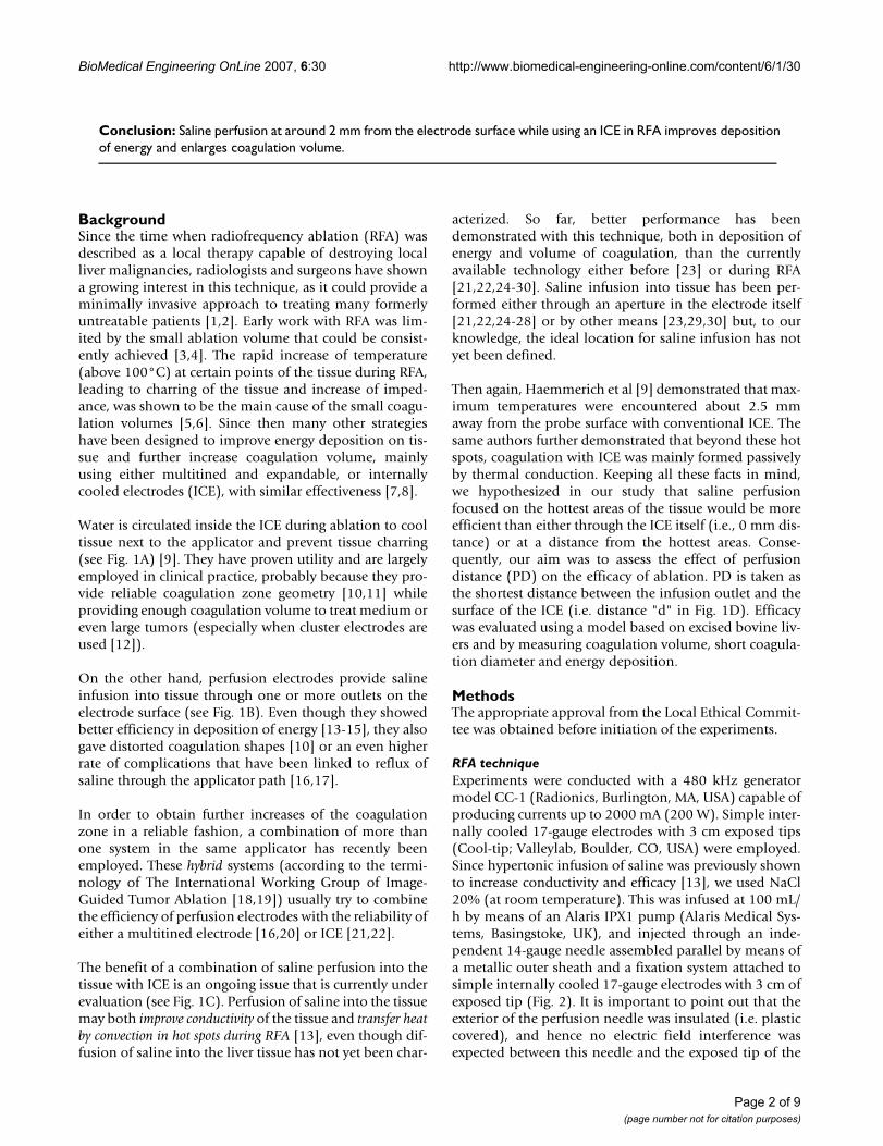
The benefit of a combination of saline perfusion into thetissue with ICE is an ongoing issue that is currently underevaluation (see Fig. 1C). Perfusion of saline into the tissuemay both improve conductivity of the tissue and transfer heatby convection in hot spots during RFA [13], even though dif-fusion of saline into the liver tissue has not yet been char-
acterized. So far, better performance has beendemonstrated with this technique, both in deposition ofenergy and volume of coagulation, than the currentlyavailable technology either before [23] or during RFA[21,22,24-30]. Saline infusion into tissue has been per-formed either through an aperture in the electrode itself[21,22,24-28] or by other means [23,29,30] but, to ourknowledge, the ideal location for saline infusion has notyet been defined.
Then again, Haemmerich et al [9] demonstrated that max-imum temperatures were encountered about 2.5 mmaway from the probe surface with conventional ICE. Thesame authors further demonstrated that beyond these hotspots, coagulation with ICE was mainly formed passivelyby thermal conduction. Keeping all these facts in mind,we hypothesized in our study that saline perfusionfocused on the hottest areas of the tissue would be moreefficient than either through the ICE itself (i.e., 0 mm dis-tance) or at a distance from the hottest areas. Conse-quently, our aim was to assess the effect of perfusiondistance (PD) on the efficacy of ablation. PD is taken asthe shortest distance between the infusion outlet and thesurface of the ICE (i.e. distance "d" in Fig. 1D). Efficacywas evaluated using a model based on excised bovine liv-ers and by measuring coagulation volume, short coagula-tion diameter and energy deposition.
MethodsThe appropriate approval from the Local Ethical Commit-tee was obtained before initiation of the experiments.
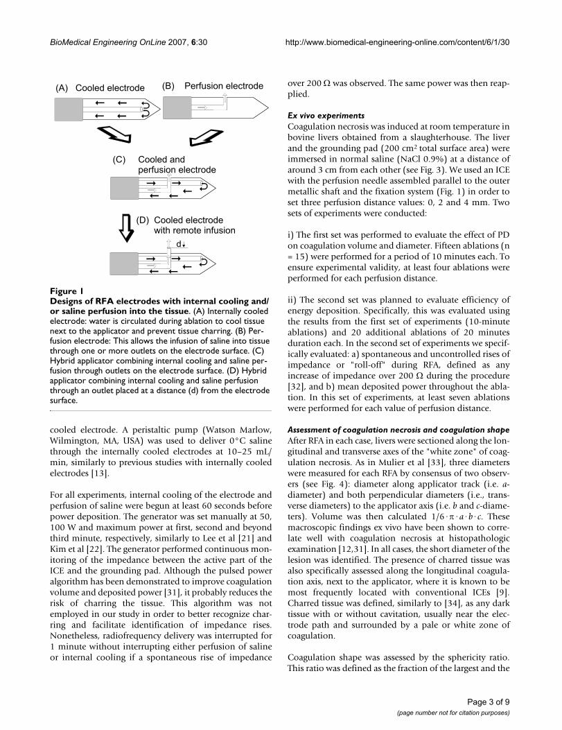
RFA techniqueExperiments were conducted with a 480 kHz generatormodel CC-1 (Radionics, Burlington, MA, USA) capable ofproducing currents up to 2000 mA (200 W). Simple inter-nally cooled 17-gauge electrodes with 3 cm exposed tips(Cool-tip; Valleylab, Boulder, CO, USA) were employed.Since hypertonic infusion of saline was previously shownto increase conductivity and efficacy [13], we used NaCl20% (at room temperature). This was infused at 100 mL/h by means of an Alaris IPX1 pump (Alaris Medical Sys-tems, Basingstoke, UK), and injected through an inde-pendent 14-gauge needle assembled parallel by means ofa metallic outer sheath and a fixation system attached tosimple internally cooled 17-gauge electrodes with 3 cm ofexposed tip (Fig. 2). It is important to point out that theexterior of the perfusion needle was insulated (i.e. plasticcovered), and hence no electric field interference wasexpected between this needle and the exposed tip of the
Page 2 of 9(page number not for citation purposes)
BioMedical Engineering OnLine 2007, 6:30 http://www.biomedical-engineering-online.com/content/6/1/30
cooled electrode. A peristaltic pump (Watson Marlow,Wilmington, MA, USA) was used to deliver 0°C salinethrough the internally cooled electrodes at 10–25 mL/min, similarly to previous studies with internally cooledelectrodes [13].
For all experiments, internal cooling of the electrode andperfusion of saline were begun at least 60 seconds beforepower deposition. The generator was set manually at 50,100 W and maximum power at first, second and beyondthird minute, respectively, similarly to Lee et al [21] andKim et al [22]. The generator performed continuous mon-itoring of the impedance between the active part of theICE and the grounding pad. Although the pulsed poweralgorithm has been demonstrated to improve coagulationvolume and deposited power [31], it probably reduces therisk of charring the tissue. This algorithm was notemployed in our study in order to better recognize char-ring and facilitate identification of impedance rises.Nonetheless, radiofrequency delivery was interrupted for1 minute without interrupting either perfusion of salineor internal cooling if a spontaneous rise of impedance
over 200 Ω was observed. The same power was then reap-plied.
Ex vivo experimentsCoagulation necrosis was induced at room temperature inbovine livers obtained from a slaughterhouse. The liverand the grounding pad (200 cm2 total surface area) wereimmersed in normal saline (NaCl 0.9%) at a distance ofaround 3 cm from each other (see Fig. 3). We used an ICEwith the perfusion needle assembled parallel to the outermetallic shaft and the fixation system (Fig. 1) in order toset three perfusion distance values: 0, 2 and 4 mm. Twosets of experiments were conducted:
i) The first set was performed to evaluate the effect of PDon coagulation volume and diameter. Fifteen ablations (n= 15) were performed for a period of 10 minutes each. Toensure experimental validity, at least four ablations wereperformed for each perfusion distance.
ii) The second set was planned to evaluate efficiency ofenergy deposition. Specifically, this was evaluated usingthe results from the first set of experiments (10-minuteablations) and 20 additional ablations of 20 minutesduration each. In the second set of experiments we specif-ically evaluated: a) spontaneous and uncontrolled rises ofimpedance or "roll-off" during RFA, defined as anyincrease of impedance over 200 Ω during the procedure[32], and b) mean deposited power throughout the abla-tion. In this set of experiments, at least seven ablationswere performed for each value of perfusion distance.
Assessment of coagulation necrosis and coagulation shapeAfter RFA in each case, livers were sectioned along the lon-gitudinal and transverse axes of the "white zone" of coag-ulation necrosis. As in Mulier et al [33], three diameterswere measured for each RFA by consensus of two observ-ers (see Fig. 4): diameter along applicator track (i.e. a-diameter) and both perpendicular diameters (i.e., trans-verse diameters) to the applicator axis (i.e. b and c-diame-ters). Volume was then calculated 1/6·π·a·b·c. Thesemacroscopic findings ex vivo have been shown to corre-late well with coagulation necrosis at histopathologicexamination [12,31]. In all cases, the short diameter of thelesion was identified. The presence of charred tissue wasalso specifically assessed along the longitudinal coagula-tion axis, next to the applicator, where it is known to bemost frequently located with conventional ICEs [9].Charred tissue was defined, similarly to [34], as any darktissue with or without cavitation, usually near the elec-trode path and surrounded by a pale or white zone ofcoagulation.
Coagulation shape was assessed by the sphericity ratio.This ratio was defined as the fraction of the largest and the
Designs of RFA electrodes with internal cooling and/or saline perfusion into the tissueFigure 1Designs of RFA electrodes with internal cooling and/or saline perfusion into the tissue. (A) Internally cooled electrode: water is circulated during ablation to cool tissue next to the applicator and prevent tissue charring. (B) Per-fusion electrode: This allows the infusion of saline into tissue through one or more outlets on the electrode surface. (C) Hybrid applicator combining internal cooling and saline per-fusion through outlets on the electrode surface. (D) Hybrid applicator combining internal cooling and saline perfusion through an outlet placed at a distance (d) from the electrode surface.
(A) Cooled electrode (B) Perfusion electrode
(C) Cooled andperfusion electrode
(D) Cooled electrodewith remote infusion
Dd
Page 3 of 9(page number not for citation purposes)
BioMedical Engineering OnLine 2007, 6:30 http://www.biomedical-engineering-online.com/content/6/1/30
average of the two remaining diameters in each lesion[10]. The closer this ratio is to 1, the more spherical theshape.
Statistical analysisContinuous data were compared by either analysis of var-iance (and Bonferroni posthoc analyses) or Kruskal-Wal-lis test when appropriate. Additionally, non linear fits (i.e.higher order regression models) and linear regressionmodels were performed in order to determine the bestlocations for perfusion of saline in ex vivo studies. Hyper-bolic functions were then fitted by using the classicmethod of least squares. The goodness of fit of a modelwas assessed by r2 (coefficient of determination), whichcan be interpreted as the proportion of the total variabilityexplained by the model. Differences with a value of α <0.05 were considered to be statistically significant.
ResultsEffect on coagulation volume, diameters and shapeTable 1 shows the results of the first set of experiments. Inall cases, the short diameter of coagulation size was one ofthe two transverse diameters. The perfusion distance hada significant effect on volume, and also on minimum andmaximum transverse diameters, as shown by the results ofthe analysis of variance. The best-fit least square functionswere always obtained with quadratic curves for volumesize (r2 = 0.58; P = 0.0054) and both transverse diameters
(Fig. 5). Volume size and both transverse diameterspeaked their values for a perfusion distance of 2 mm.
The mean short diameter was greater for a perfusion dis-tance of 2 mm than for the other perfusion distances (P <0.05) (Table 1), but only the former comparisonremained statistically significant in a posthoc analysis.Nevertheless, no significant differences were encounteredin axial diameter for different perfusion distances, eventhough the greatest mean absolute values were obtainedfor a perfusion distance of 0 mm. Therefore, assessment ofthe sphericity ratio (Table 1) showed less spherical coagu-lation in the 0-mm group, compared to both 2-mm and 4-mm. Accordingly, a thirty per cent increase of mean vol-ume size was demonstrated in the 2-mm group over theremaining groups (Table 1).
Effect on energy depositionIn the second set of experiments, the best-fit least squarefunction was once more obtained with a quadratic curvefor deposited power during the ablation (Fig. 6A). Depos-ited power during RFA thus peaked for a perfusion dis-tance of 2 mm, reaching a mean value of 171.2 ± 9.8 W.This matched well with the higher relative frequency ofexperiments with any uncontrolled rise of impedance forperfusion distances of 0 and 4 mm (Fig. 6B). As expected,longer experiments (i.e. 20 minutes) were linked withhigher frequency of uncontrolled impedance rise (Fig.
Applicator used in the experiments to test the effect of perfusion distanceFigure 2Applicator used in the experiments to test the effect of perfusion distance. An insulated perfusion needle (arrow-heads) attached to a metallic outer sheath (solid arrows) by means of two fixation systems (open arrows) and a 17-gauge inter-nally cooled electrode with a 3 cm exposed tip (broken arrows) (A). Once the metallic outer sheath is fitted to the internally cooled electrode, the perfusion needle remains parallel and midway from the exposed tip of the internally cooled electrode (B). The bottom photo shows the case of a perfusion distance of 2 mm.
Page 4 of 9(page number not for citation purposes)

BioMedical Engineering OnLine 2007, 6:30 http://www.biomedical-engineering-online.com/content/6/1/30
6B). The mean power found for perfusion distances of 0and 4 mm were 166.3 ± 12.1 W and 151.6 ± 16.6 W,respectively.
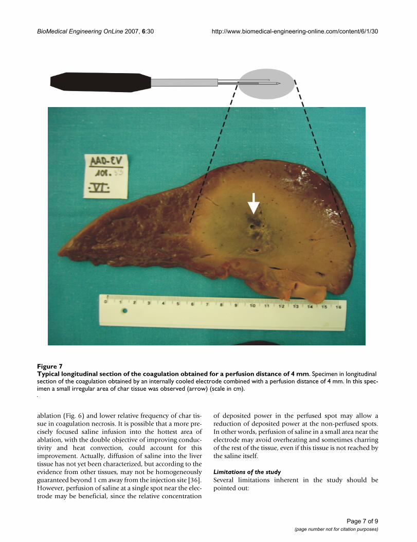
On macroscopic examination, several degrees of char tis-sue in irregular areas were observed in 12 (34.2%) of theexperiments, usually near the electrode path (Fig. 7). It is
noteworthy that in only 2 experiments (16.7%) in the 2-mm distance group was char tissue observed.
DiscussionIn RFA of liver malignancies, the safe acquisition of a largeablation volume is of paramount importance for thistechnique to be accepted as a clinical routine [3]. In thissetting, either internally cooled electrodes or multitinedexpandable electrodes have been shown to accomplishthis goal better than perfusion electrodes [3,16]. In orderto further increase coagulation zone size, a combinationof more than one system has recently been employed inthe same applicator. These hybrid electrodes usually com-bine perfusion of saline with either a multitined electrode[16,20] or an ICE [21,22]. Saline infusion is generallyinjected into the tissue either through an aperture at itsactive tip [21,22,24-28] or directly into the tissue itself[23,29,30]. Concerning RFA with ICE, Haemmerich et al[9] demonstrated that maximum temperatures wereencountered about 2.5 mm away from the probe surface.These authors further demonstrated that beyond these hotspots, coagulation was mainly formed passively by ther-mal conduction. Lorentzen [35] had previously demon-strated that a concentric ring of char tissue at about 3 mmfrom the needle tract was often observed during ablationwith internally cooled electrodes and a non-pulsed poweralgorithm (Fig. 8). Moreover, this charring tissue waslinked to a significant fall in deposited power during abla-tion [9,35]. On the other hand, Goldberg et al [13] statedthat saline perfusion may improve conductivity of the tis-sue and transfer heat by convection in hot spots duringRFA. We therefore hypothesized that a hybrid applicatorbased on an internally cooled electrode combined withsaline infusion into the tissue may be optimized in termsof deposited power and coagulation volume when theperfusion distance was precisely injected at these hotspots.
In our study we chose to assess three values of perfusiondistance: 0, 2 and 4 mm. Results from the general linearmodel and best fit of least square functions confirmedthat perfusion distance had a significant effect on bothvolume and minimum and maximum transverse diame-ters. In general, the best results were always obtained at adistance of 2 mm, showing at least a thirty per centincrease in volume of the coagulation necrosis over theother distances tested. Likewise, a significant increase ofnearly twenty-five per cent was yielded in the 2 mm groupover the 0 mm group in mean short diameter of the coag-ulation necrosis. This improvement could be important,taking into account that the short diameter may be one ofthe main determinants of technical success in RFA in aclinical setting [18]. In a similar experimental approachwith ex vivo bovine livers, Lee et al [21] further demon-strated that the addition of infusion at 0-mm distance
Nomenclature employed to measure coagulation diametersFigure 4Nomenclature employed to measure coagulation diameters. After ablations, livers were sectioned along the longitudinal and transverse axes of the "white zone" of coag-ulation necrosis (gray in figure). Three diameters were meas-ured by consensus of two observers: diameter along applicator track (a) and both perpendicular diameters (i.e., transverse diameters) to the applicator axis (b and c). The perfusion distance is d.
Aa
Bb BbCc
Dd
Transversal viewAxial view
Experimental setup of the ex vivo studyFigure 3Experimental setup of the ex vivo study. Coagulation necrosis was induced at room temperature using bovine liv-ers. The livers were partially immersed (D2 ≈ D3 ≈ 5–6 cm) in normal saline (NaCl 0,9%) at around 3 cm (D1) from a ≈ 200 cm2 grounding pad, G.
D1
D2
D3
RF Generator
G
Page 5 of 9(page number not for citation purposes)

BioMedical Engineering OnLine 2007, 6:30 http://www.biomedical-engineering-online.com/content/6/1/30
coupled with ICE may improve both the mean volume ofcoagulation necrosis, in comparison with a single ICE(from 13.1 to 43.7 cm3, respectively), and mean shortdiameter (from 2.6 to 3.4 cm, respectively). In our studywe obtained similar figures in both the short diameter andvolume for a perfusion distance of 0 mm (4.0 ± 0.4 cmand 53.0 ± 15.0 cm3, respectively) but these values weresignificantly improved when the perfusion distance was 2mm (5.3 ± 0.5 cm and 91.7 ± 18.2 cm3, respectively).However, when the perfusion distance was increased, the
short diameter of the lesion did not increase, in fact, thevolume was significantly reduced. This phenomenon wasalso shown by the decreasing step of the hyperbolic func-tion of volume size related to the perfusion distances > 2mm (Fig. 5A). Concerning coagulation shape, infusion ofsaline at a distance from the ICE (2 mm and 4 mmgroups), in contrast to around the ICE (0-mm group),seemed to increase sphericity of the lesion (mean spheric-ity ratio: 1.1 and 1.5, respectively). These figures matchwell with the results published by Pereira et al [10], whodescribed a sphericity ratio of 1.38 for cluster cool-tip elec-trodes and 1.42 for RITA electrodes in a pig liver in vivomodel.
The improvement in coagulation volume matched wellwith a significant increase in deposited power, lower rela-tive frequency of uncontrolled impedance rise during
Effect of perfusion distance on energy deposition into the tis-sueFigure 6Effect of perfusion distance on energy deposition into the tissue. Three perfusion distances were tested: 0 mm (n = 7), 2 mm (n = 12) and 4 mm (n = 16). Scatter plot shows non-linear (quadratic) relationship between distance and deposited power (A). Goodness of fit of the model is assessed by r2. Note the improved effect at perfusion dis-tance of 2 mm on deposition of power. Additionally, a drop-line chart (B) summarizes the observed relative frequency of an uncontrolled rise of impedance within two RFA durations (10 and 20 min) for the three values of perfusion distance. Note the lower rate of impedance rise during the procedure at a distance of 2 mm. In all cases, longer durations (20 min-utes) were linked to a higher rate of impedance rise.
r2= .32
p=.002
Distance (mm)
Distance (mm)
Po
we
r(W
)
Ris
eo
fim
pe
da
nc
e-r
ela
tiv
efr
eq
ue
nc
y(%
)
(A)(B)
Table 1: Effect of perfusion distance on coagulation volume, diameter and shape
Perfusion distance (mm) 0 (n = 4) 2 (n = 5) 4 (n = 6) P*
Volume size (cm3) 53.0 ± 15.0 91.7 ± 18.2 63.9 ± 11.7 <0.05Axial diameter (cm) 6.2 ± 1.0 6.0 ± 0.2 5.2 ± 0.5 NSMinimum transverse diameter (cm) 4.0 ± 0.4 5.3 ± 0.5 4.5 ± 0.8 <0.05Maximum transverse diameter (cm) 4.0 ± 0.4 5.5 ± 0.5 5.2 ± 0.5 <0.05Sphericity † 1.5 ± 0.2 1.1 ± 0.1 1.1 ± 0.2 <0.01
The perfusion distance was defined as the shortest distance between the saline outlet and the surface of the internally cooled electrode* Overall statistical significance. Statistically significant (P < 0.05). NS: no significant differences† Fraction of the largest and the average of the two remaining diameters of the thermal lesion (see text)
Effect of perfusion distance on volume coagulation and coag-ulation diametersFigure 5Effect of perfusion distance on volume coagulation and coagulation diameters. Three values of perfusion dis-tance were tested: 0 mm (n = 4), 2 mm (n = 5) and 4 mm (n = 6). Scatter plot shows non-linear (quadratic) relationship between distance and coagulation volume (A), maximum transverse diameter of coagulation (B), and minimum trans-verse diameter (C). Goodness of fit of the models is individu-ally assessed by r2. Note the improved effect at 2 mm distance.
r2= .43
p=.034
r2= .65
p=.0017
r2= .58
p=.0054
Vo
lum
e(c
m)
3
Distance (mm)
Distance (mm) Distance (mm)
Min
imu
mtr
an
sv
ers
ed
iam
ete
r(c
m)
Ma
xim
um
tra
ns
ve
rse
dia
me
ter
(cm
)
(A)
(B) C( )
Page 6 of 9(page number not for citation purposes)
BioMedical Engineering OnLine 2007, 6:30 http://www.biomedical-engineering-online.com/content/6/1/30
ablation (Fig. 6) and lower relative frequency of char tis-sue in coagulation necrosis. It is possible that a more pre-cisely focused saline infusion into the hottest area ofablation, with the double objective of improving conduc-tivity and heat convection, could account for thisimprovement. Actually, diffusion of saline into the livertissue has not yet been characterized, but according to theevidence from other tissues, may not be homogeneouslyguaranteed beyond 1 cm away from the injection site [36].However, perfusion of saline at a single spot near the elec-trode may be beneficial, since the relative concentration
of deposited power in the perfused spot may allow areduction of deposited power at the non-perfused spots.In other words, perfusion of saline in a small area near theelectrode may avoid overheating and sometimes charringof the rest of the tissue, even if this tissue is not reached bythe saline itself.
Limitations of the studySeveral limitations inherent in the study should bepointed out:
Typical longitudinal section of the coagulation obtained for a perfusion distance of 4 mmFigure 7Typical longitudinal section of the coagulation obtained for a perfusion distance of 4 mm. Specimen in longitudinal section of the coagulation obtained by an internally cooled electrode combined with a perfusion distance of 4 mm. In this spec-imen a small irregular area of char tissue was observed (arrow) (scale in cm).
Page 7 of 9(page number not for citation purposes)

BioMedical Engineering OnLine 2007, 6:30 http://www.biomedical-engineering-online.com/content/6/1/30
1. This is an ex vivo study in healthy bovine livers. There-fore, the actual clinical setting may be substantially differ-ent, not only because of the known "heat sink effect" ofblood perfusion but also because of tumor tissue charac-teristics.
2. Even though the pulsed power algorithm has beendemonstrated to improve coagulation volume and depos-ited power [31], it probably reduces the risk of tissue char-ring. This algorithm was not employed in our study inorder to facilitate impedance rises and recognition ofcharring. It is conceivable that the use of this algorithmcould improve or modify certain results.
3. Precise perfusion of saline was performed by a per-fusion needle held by means of two fixation systemsattached to the electrode to guarantee the parallel positionin the desired location. However, the exactitude of the dis-tance between the ICE and infusion needle at the tip zonewas not measured precisely.
4. The coagulation shape is of paramount importance inclinical practice and was evaluated by the sphericity ratioin this work. Although a more comprehensive evaluationof the coagulation shape should be mandatory in upcom-ing research, it is outside the scope of this article.
Practical applicationWhile using internally cooled electrodes for RFA, coupledwith perfusion of saline into the tissue, the proper loca-tion of the saline perfusion, as discussed in this study,should enhance and focus energy dissipation in the tar-
geted tissue. This configuration should lead to better per-formance in liver tumor RFA.
ConclusionPerfusion of saline at around 2 mm from the electrodesurface while using an internally cooled electrode in RFAimproves deposition of energy and coagulation volume.
Competing interestsDrs. F. Burdío, E.J. Berjano, A. Navarro and A. Güemes areapplying for a patent relating to the content of the manu-script. All other authors declare that they have no compet-ing interests.
Authors' contributionsFB conceived the study and participated in its design andcoordination; EJB and JMB participated in the design ofthe study and performed the statistical analysis; AN partic-ipated in the design of the study and carried out the exper-iments; AGU, RS, JS, AGO, IC and ET carried out theexperiments; LG participated in the design of the studyand helped to draft the manuscript; TC conducted the his-topathologic examinations; RL and MG participated inthe design of the study. All authors have read andapproved the final manuscript.
AcknowledgementsWe would like to thank the R+D+i Linguistic Assistance Office at the Pol-ytechnic University of Valencia for their help in revising this paper and the reviewers for their constructive comments.
This work was partially supported by a grant for medical research from Spanish Government (PETRI 2005/0353), by the "Programa de Promoción de la Investigación Biomédica y en Ciencias de la Salud del Ministerio de
Char ring created by a single internally cooled electrode with an effective area of 3 cm in lengthFigure 8Char ring created by a single internally cooled electrode with an effective area of 3 cm in length. Longitudinal (A) and cross section (B) of the coagulation obtained by a single 3 cm exposed tip internally cooled electrode at 1800 mA (maxi-mum current) for 10 minutes without using either saline perfusion into the tissue or an impedance control algorithm (unpub-lished personal experiments in bovine liver ex vivo). A ring of char tissue surrounding the electrode track is clearly shown (arrows).
Page 8 of 9(page number not for citation purposes)
BioMedical Engineering OnLine 2007, 6:30 http://www.biomedical-engineering-online.com/content/6/1/30
Sanidad y Consumo" of Spain (PI052498), and the "Plan Nacional de Inves-tigación Científica, Desarrollo e Innovación Tecnológica del Ministerio de Educación y Ciencia" of Spain (TEC 2005-04199/TCM). Finally, the publica-tion cost was supported by the "Programa de Apoyo a la Investigación y el Desarrollo" of the Valencia Polytechnic University.
References1. Poon RT, Fan ST, Tsang FH, Wong J: Locoregional therapies for
hepatocellular carcinoma: a critical review from the sur-geon's perspective. Ann Surg 2002, 235:466-486.
2. Tanabe KK, Curley SA, Dodd GD, Siperstein AE, Goldberg SN: Radi-ofrequency ablation: the experts weigh in. Cancer 2004,100:641-650.
3. De Sanctis JT, Goldberg SN, Mueller PR: Percutaneous treatmentof hepatic neoplasms: A review of current techniques. Cardi-ovasc Intervent Radiol 1998, 21:273-296.
4. Solbiati L, Ierace T, Goldberg SN, Sironi S, Livraghi T, Fiocca R, Ser-vadio G, Rizzatto G, Mueller PR, Del Maschio A, Gazelle GS: Percu-taneous US-guided radio-frequency tissue ablation of livermetastases: treatment and follow-up in 16 patients. Radiology1997, 202:195-203.
5. Nath S, Haines DE: Biophysics and pathology of catheterenergy delivery systems. Prog Cardiovasc Dis 1995, 37:185-204.
6. Organ LW: Electrophysiologic principles of radiofrequencylesion making. Appl Neurophysiol 1976, 39:69-76.
7. de Baere T, Denys A, Wood BJ, Lassau N, Kardache M, Vilgrain V,Menu Y, Roche A: Radiofrequency liver ablation: experimentalcomparative study of water-cooled versus expandable sys-tems. AJR Am J Roentgenol 2001, 176:187-192.
8. Shibata T, Shibata T, Maetani Y, Isoda H, Hiraoka M: Radiofre-quency ablation for small hepatocellular carcinoma: pro-spective comparison of internally cooled electrode andexpandable electrode. Radiology 2006, 238:346-353.
9. Haemmerich D, Chachati L, Wright AS, Mahvi DM, Lee FT Jr., Web-ster JG: Hepatic radiofrequency ablation with internallycooled probes: effect of coolant temperature on lesion size.IEEE Trans Biomed Eng 2003, 50:493-500.
10. Pereira PL, Trubenbach J, Schenk M, Subke J, Kroeber S, Schaefer I,Remy CT, Schmidt D, Brieger J, Claussen CD: Radiofrequencyablation: in vivo comparison of four commercially availabledevices in pig livers. Radiology 2004, 232:482-490.
11. Ng KK, Lam CM, Poon RT, Shek TW, Yu WC, To JY, Wo YH, LauCP, Tang TC, Ho DW, Fan ST: Porcine liver: morphologic char-acteristics and cell viability at experimental radiofrequencyablation with internally cooled electrodes. Radiology 2005,235:478-486.
12. Goldberg SN, Solbiati L, Hahn PF, Cosman E, Conrad JE, Fogle R,Gazelle GS: Large-volume tissue ablation with radio frequencyby using a clustered, internally cooled electrode technique:laboratory and clinical experience in liver metastases. Radiol-ogy 1998, 209:371-379.
13. Goldberg SN, Ahmed M, Gazelle GS, Kruskal JB, Huertas JC, HalpernEF, Oliver BS, Lenkinski RE: Radio-frequency thermal ablationwith NaCl solution injection: effect of electrical conductivityon tissue heating and coagulation-phantom and porcine liverstudy. Radiology 2001, 219:157-165.
14. Burdio F, Burdio JM, Navarro A, Ros P, Guemes A, Sousa R, TejeroE, Lozano R: Electric influence of NaCl concentration into thetissue in radiofrequency ablation. Radiology 2004, 232:932-933.
15. Brieger J, Pereira PL, Trubenbach J, Schenk M, Krober SM, Schmidt D,Aube C, Claussen CD, Schick F: In vivo efficiency of four com-mercial monopolar radiofrequency ablation systems: a com-parative experimental study in pig liver. Invest Radiol 2003,38:609-616.
16. Gillams AR, Lees WR: CT mapping of the distribution of salineduring radiofrequency ablation with perfusion electrodes.Cardiovasc Intervent Radiol 2005, 28:476-480.
17. Kettenbach J, Kostler W, Rucklinger E, Gustorff B, Hupfl M, Wolf F,Peer K, Weigner M, Lammer J, Muller W, Goldberg SN: Percutane-ous saline-enhanced radiofrequency ablation of unresectablehepatic tumors: initial experience in 26 patients. AJR Am JRoentgenol 2003, 180:1537-1545.
18. Goldberg SN, Grassi CJ, Cardella JF, Charboneau JW, Dodd GD III,Dupuy DE, Gervais D, Gillams AR, Kane RA, Lee FT Jr., Livraghi T,McGahan J, Phillips DA, Rhim H, Silverman SG: Image-guided
tumor ablation: standardization of terminology and report-ing criteria. Radiology 2005, 235:728-739.
19. Nour SG: Standardization of terms and reporting criteria forimage-guided tumor ablation. Radiology 2004, 232:626-627.
20. Miao Y, Ni Y, Yu J, Zhang H, Baert A, Marchal G: An ex vivo studyon radiofrequency tissue ablation: increased lesion size byusing an "expandable-wet" electrode. Eur Radiol 2001,11:1841-1847.
21. Lee JM, Han JK, Chang JM, Chung SY, Kim SH, Lee JY, Lee MW, ChoiBI: Radiofrequency ablation of the porcine liver in vivo:increased coagulation with an internally cooled perfusionelectrode. Acad Radiol 2006, 13:343-352.
22. Kim SK, Seo JW: Radiofrequency ablation with a new perfused-cooled electrode using a single pump: an experimental studyin ex vivo bovine liver. Cardiovasc Intervent Radiol 2005,28:779-788.
23. Lobo SM, Afzal KS, Ahmed M, Kruskal JB, Lenkinski RE, Goldberg SN:Radiofrequency ablation: modeling the enhanced tempera-ture response to adjuvant NaCl pretreatment. Radiology 2004,230:175-182.
24. Ni Y, Miao Y, Mulier S, Yu J, Baert AL, Marchal G: A novel "cooled-wet" electrode for radiofrequency ablation. Eur Radiol 2000,10:852-854.
25. Miao Y, Ni Y, Yu J, Marchal G: A comparative study on validationof a novel cooled-wet electrode for radiofrequency liverablation. Invest Radiol 2000, 35:438-444.
26. Lee JM, Han JK, Kim SH, Lee JY, Shin KS, Choi BI: An ex-vivo exper-imental study on optimization of bipolar radiofrequencyliver ablation using perfusion-cooled electrodes. Acta Radiol2005, 46:443-451.
27. Lee JM, Han JK, Kim SH, Lee JY, Park HS, Eo H, Choi BI: Radiofre-quency ablation in the liver using two cooled-wet electrodesin the bipolar mode. Eur Radiol 2005, 15:2163-2170.
28. Lee JM, Han JK, Kim SH, Sohn KL, Choi SH, Choi BI: Bipolar radi-ofrequency ablation in ex vivo bovine liver with the open-perfused system versus the cooled-wet system. Eur Radiol2005, 15:759-764.
29. Nour SG, Goldberg SN, Michel I, Kim E, Lewin J: MR guidance andmonitoring of saline-augmented radiofrequency interstitialthermal ablation. Radiology 2002, 225(P):218.
30. Nour SG, Wacker FK, Amstrong C, Goldberg SN, Duerk JL, Lewin J,Zhang SX: Does combined "coolwet" radiofrequency intersti-tial thermal ablation (RF-ITA) warrant clinical application?Radiology 2002, 225(P):163.
31. Goldberg SN, Stein MC, Gazelle GS, Sheiman RG, Kruskal JB, ClouseME: Percutaneous radiofrequency tissue ablation: optimiza-tion of pulsed-radiofrequency technique to increase coagula-tion necrosis. J Vasc Interv Radiol 1999, 10:907-916.
32. Sugimori K, Morimoto M, Shirato K, Kokawa A, Tomita N, Saito T,Nozawa A, Hara M, Sekihara H, Tanaka K: Radiofrequency abla-tion in a pig liver model: effect of transcatheter arterialembolization on coagulation diameter and histologic charac-teristics. Hepatol Res 2002, 24:164-173.
33. Mulier S, Ni Y, Frich L, Burdio F, Denys AL, De Wispelaere JF, DupasB, Habib N, Hoey M, Jansen MC, Lacrosse M, Leveillee R, Miao Y, Mul-ier P, Mutter D, Ng KK, Santambrogio R, Stippel D, Tamaki K, vanGulik TM, Marchal G, Michel L: Experimental and clinical radiof-requency ablation: proposal for standardized description ofcoagulation size and geometry. Ann Surg Oncol 2007,14:1381-1396.
34. McGahan J, Schneider P, Brock JM, Tesluk H: Treatment of livertumors by percutaneous radiofrequency electrocautery.Seminars in Interventional Radiology 1993, 10:143-149.
35. Lorentzen T: A cooled needle electrode for radiofrequencytissue ablation: thermodynamic aspects of improved per-formance compared with conventional needle design. AcadRadiol 1996, 3:556-563.
36. Hoey MF, Paul S: Interstitial electrolyte infusion creates a liq-uid electrode for controlled application of high power radiof-requency energy: 1998. Proceedings of 20th Annual InternationalConference of the IEEE Engineering in Medicine and Biology Society 1998,20:1064-1067.
Page 9 of 9(page number not for citation purposes)
http://www.ncbi.nlm.nih.gov/entrez/query.fcgi?cmd=Retrieve&db=PubMed&dopt=Abstract&list_uids=9688795
http://www.ncbi.nlm.nih.gov/entrez/query.fcgi?cmd=Retrieve&db=PubMed&dopt=Abstract&list_uids=9688795
http://www.ncbi.nlm.nih.gov/entrez/query.fcgi?cmd=Retrieve&db=PubMed&dopt=Abstract&list_uids=8988211
http://www.ncbi.nlm.nih.gov/entrez/query.fcgi?cmd=Retrieve&db=PubMed&dopt=Abstract&list_uids=8988211
http://www.ncbi.nlm.nih.gov/entrez/query.fcgi?cmd=Retrieve&db=PubMed&dopt=Abstract&list_uids=8988211
http://www.ncbi.nlm.nih.gov/entrez/query.fcgi?cmd=Retrieve&db=PubMed&dopt=Abstract&list_uids=7831466
http://www.ncbi.nlm.nih.gov/entrez/query.fcgi?cmd=Retrieve&db=PubMed&dopt=Abstract&list_uids=7831466
http://www.ncbi.nlm.nih.gov/entrez/query.fcgi?cmd=Retrieve&db=PubMed&dopt=Abstract&list_uids=1052287
http://www.ncbi.nlm.nih.gov/entrez/query.fcgi?cmd=Retrieve&db=PubMed&dopt=Abstract&list_uids=1052287
http://www.ncbi.nlm.nih.gov/entrez/query.fcgi?cmd=Retrieve&db=PubMed&dopt=Abstract&list_uids=9807561
http://www.ncbi.nlm.nih.gov/entrez/query.fcgi?cmd=Retrieve&db=PubMed&dopt=Abstract&list_uids=9807561
http://www.ncbi.nlm.nih.gov/entrez/query.fcgi?cmd=Retrieve&db=PubMed&dopt=Abstract&list_uids=9807561
http://www.ncbi.nlm.nih.gov/entrez/query.fcgi?cmd=Retrieve&db=PubMed&dopt=Abstract&list_uids=8796717
Related Documents


