R.F. Remote Control Radio Frequency (RF) remote control utilises radio frequency transmission to instantly pass data from one point to another without the restriction of physical wiring or cables. RF does not require line of sight and does not have to be aimed at a specific point in order to be detected. RF is emitted in all directions from the transmitter and can pass through physical structures making it an extremely useful communication method. Tipping Point All fuel tankers are required to shutdown their electrical systems in the event of a roll over. Accuracy and reliability is paramount in this circumstance as a faulty or poorly designed sensor can lead to all truck electricals being turned off mid corner with disastrous results. iROS uses a 2-axis accelerometer along with sophisticated software to monitor both angle and g-forces to determine if a rollover has really occurred before sending out the signal to turn off the power. This same detection technology is also used in the iROS-T to help alert drivers to dangerous lean angles while raising their tipper bodies. A three staged warning gives the operator ample time to stop the body raising, potentially saving lives and equipment damage. User Programmable The Programmable Switch Panel is able to control up to 8 separate functions. Highly configurable, and featuring momentary or latching switch function, the user can select from multiple switch symbols stored in the memory of the unit to display on the integrated backlit LCD. The switch panel and receiver mod- ules communicate using a dedicated CAN communica- tion protocol and can be expanded by connecting multiple receivers to the CAN line.

Welcome message from author
This document is posted to help you gain knowledge. Please leave a comment to let me know what you think about it! Share it to your friends and learn new things together.
Transcript

R.F. Remote ControlRadio Frequency (RF) remote control utilises radio frequency transmission to instantly pass data from one point to another without the restriction of physical wiring or cables.
RF does not require line of sight and does not have to be aimed at a specific point in order to be detected. RF is emitted in all directions from the transmitter and can pass through physical structures making it an extremely useful communication method.
Tipping PointAll fuel tankers are required to shutdown their electrical systems in the event of a roll over. Accuracy and reliability is paramount in this circumstance as a faulty or poorly designed sensor can lead to all truck electricals being turned off mid corner with disastrous results.
iROS uses a 2-axis accelerometer along with sophisticated software to monitor both angle and g-forces to determine if a rollover has really occurred before sending out the signal to turn off the power.
This same detection technology is also used in the iROS-T to help alert drivers to dangerous lean angles while raising their tipper bodies. A three staged warning gives the operator ample time to stop the body raising, potentially saving lives and equipment damage.
User ProgrammableThe Programmable Switch Panel is able to control up to 8 separate functions. Highly configurable, and featuring momentary or latching switch function, the user can select from multiple switch symbols stored in the memory of the unit to display on the integrated backlit LCD. The switch panel
and receiver mod-ules communicate using a dedicated CAN communica-tion protocol and can be expanded by connecting multiple receivers to the CAN line.

Switching SystemsESM 36
Programmable Switch Panel 38
Radio Remote Control 40
Rollover 42
Tipper 43
Voltage Sensor 44
Headlights On Units 45
Hand Brake Alarm Module 46
IONNIC Idle Timer 47
Idle Timers 48
Low Coolant Alarm 50

36
Switching Systems
ESM
Circuit Breaker
Switch Input
Switch Panel
Toggle Switch
Input 10
Outputs 1 & 2
ESM
Inputs 1 & 2
Outputs 10, 11, 12, 13
• Electronically monitored switch centre with inbuilt circuit monitoring and protection.
• Each output surge-protected to 10A.
• 10 inputs, 13 outputs.
• 1 grouped input – 4 separate outputs
• On board LEDs indicate circuit output.
• Saves space and installation time.
• Multi-voltage
• Environmentally sealed - IP67.
• Available in positive, or positive/negative switched models.
Voltage : 12-24VCurrent Draw : 10mA @ 13.8VInputs : 10Outputs : 13Max. Output Current Rating (per output) : 7.5AMax. Output Current Rating (total) : 50AConstruction : PolycarbonateIngress Protection : IP67Approvals : C-TickOperating Temperature : -40°C to 85°C
The ESM is an electronically monitored switch centre with inbuilt circuit monitoring and protection.
The unit can be used in any application in which conventional circuit protection may have been used in the past.
The ESM can be used for any application from connecting auxiliary lighting off original vehicle tails lights, eg Minebar hook up, to using it to monitor and protect a range of auxiliary equipment switched off the original vehicle inputs or after market toggle, rocker switches etc.
If a short or over current condition presents on any of the outputs then the output will shut down. This will then cycle 3 times (on/off).
If the over current situation is still present the output will then shut down permanently until the input is turned off.
Inputs 1 to 9 controls ouputs 1 to 9 respectively.
Input 10 controls outputs 10, 11, 12, 13.
Inductive loads must not be used on the input or output circuits without additional external protection. Failure to do so will result in damage to the unit and will void warranty.

37
Switching Systems
Accessories & Related ProductsPart No. Description
ESM9001 Connection Kit
DET-20 Crimp tool. Size 20
HDT-48-00 Crimp tool. Size 12, 16, 20 & 22
DET-RT Multi-use hook tool
CB187-XX Circuit breaker. Surface mount series See page 160 for complete range
CB255-XX Circuit breaker. Panel mount series See page 160 for complete range
AMIXX AMI Fuse Series See page 172 for complete range
AMIFH AMI Fuse holder. Surface mount
ESM9001
DET20 HDT-48-00 DET-RT
AMIFHAMIXXCB187-XX CB255-XX
ESM MiniThe ESM006 is a compact version of our original ESM with the following specifications:
• 6 Input. • 6 Output. • Max. Current Draw 25A @ 13.8V.
16mm
37mm119mm
75m
m
102mm
134m
mM6
Due for release 2nd quarter of 2015.
ESMPart No. Switching Notes
ESM0013 Positive —
ESM2013 Positive & Negative ESM2013 will switch on both positive or negative inputs, diodes may be required to prevent false triggering.

38
Switching Systems
Programmable Switch Panel System Integration
• User programmable LCD switch panel.
• Switch panel can control up to 8 separate functions.
• User selectable switch function symbols.
• Clean contacts.
• Efficient system wiring via CAN communication.
• Fixed or momentary outputs.
• Dimmable backlit switch panel.
• Epoxy sealed receivers.
• On-board diagnostics.
• Audible user feedback.
• Multi-voltage.
• Ability to add multiple receivers.
• Lightweight panel design - ideal for various mounting options.
Pro
gram
mab
le S
witch
Pan
el
PCS-01
PCS-02
Voltage : 10-24VCurrent Rating : 10A max. per circuitPanel Material : ABS
The Programmable Switch Panel can be installed into any vehicle system and can control up to 8 separate functions per switch panel.
Each switch panel connects to multiple receivers via a single 3 core CAN data cable, the “backbone”.
A Deutsch “Y” piece connector is used to branch out from the “backbone” to the receivers which in turn can control up to 4 outputs each.
0462-201-1631
0462-201-1631103349
DT04-3P-P007
DT06-3S
DT06-3S
DT06-3S
W3S-1939W3S-1939
103349
Deutsch “Y” Piece ConnectionW3S

39
Switching Systems
103349
BMM-014BMM-013
0462-201-16310460-202-1631DT04-3P-P007 W3S-1939DT06-3SDT04-3P
PCS-01 PCS-02
127mm27mm
85m
m 86mm
95mm
27m
m48
mm
Ø 5.5mmØ 2.5mm
DET16 HDT-48-00 DET-RT
Programmable Switch PanelPart No. Description
PCS-01 Switch Panel
PCS-02 Receiver
Accessories & Related ProductsPart No. Description
103349 CAN data cable - metre
DT04-3P-P007 Deutsch DT Series - Receptacle “Y” Piece. Includes wedgelocks & contacts
DT04-3P Deutsch DT Series - Receptacle - 3 circuit
W3P Deutsch DT Series - Wedgelock - Receptacle - Green. Suits DT04-3P
W3P-1939 Deutsch DT Series - Wedgelock - Receptacle - Blue. Suits DT04-3P
DT06-3S Deutsch DT Series - Plug - 3 circuit
W3S Deutsch DT Series - Wedgelock - Plug - Orange. Suits DT06-3S
W3S-1939 Deutsch DT Series - Wedgelock - Plug - Blue. Suits DT06-3S
0460-202-1631 Contact - Pin - Solid - Gold Plated - Size 16
0462-201-1631 Contact - Socket - Solid - Gold Plated - Size 16
DET16 Crimp tool - Size 16
HDT-48-00 Crimp tool - Size 12, 16, 20 & 22
DET-RT Multi-use hook tool
BMM-013 Mount for PCS-01. Adhesive/bolt-down
BMM-014 Mount for PCS-01. Bolt-down
W3SW3P W3P-1939

40
Switching Systems
DIP Switches
Typical Range : 90m Frequency : 433 MHzCurrent Rating : 5A max. per outputBattery : Pendant 2 x AA
Fob 1 x CR2032Transmitter Battery Life : 100,000 activationsReceiver Cable Length : 300mmEncryption : Rolling Codes
• 4 output, user programmable remote switching system.
• 2 transmitter styles available: - Palm-sized fob - Heavy duty pendant
• Up to 90 metre range.
• Rolling codes, secure encryption.
• Multiple transmitters able to be paired with single receiver.
• All 4 outputs can be momentary or latching.
• Hard-wired interlock feature on 2 outputs.
KitsPart No. Voltage Transmitter Style Contents
R15-R12-F 12 Fob 1 x R1500-R12, 1 x R1000-TF4
R15-R24-F 24 Fob 1 x R1500-R24, 1 x R1000-TF4
R15-R12-P 12 Pendant 1 x R1500-R12, 1 x R1000-TR4
R15-R24-P 24 Pendant 1 x R1500-R24, 1 x R1000-TR4
Rad
io R
emot
e Con
trol
R1500-R12
R1000-TR4
R1000-TF4
Kits: R15-R12-F, R15-R24-F
Kits: R15-R12-P, R15-R24-P
DIP switches found inside receiver enclosure can be set to achieve either latching or momentary for each output respectively.
The Interlock Override inputs can be used to manually override outputs 1 and 2 only.
Input 2 Interlock Override
Input 1 Interlock Override
+-
Input 4
R.F
. Pro
cess
or
Input 3
Input 2
Input 1
1 2 3 4

41
Switching Systems
ComponentsPart No. Voltage Description
R1500-R12 12 Receiver
R1500-R24 24 Receiver
R1000-TF4 12-24 Transmitter - Fob style
R1000-TR4 12-24 Transmitter - Pendant style
R1500-R12, R1500-R24 R1000-TR4R1000-TF4
51mm
84m
m17
mm
Ø 10mm174mm
62m
m54
mm
190mm
109mm
120mm
132mm
37m
m78
mm
Ø 5mm

42
Switching Systems
RolloverPart No. Description
IROS AS2809 compliant rollover switch
Rol
love
r
• AS2809 compliant rollover switch.
• Solid state electronics.
• Microprocessor controlled.
• Multi-voltage.
• Senses vertical & horizontal axis through an accelerometer (angle and G-force sensing device).
• Conducts system self-tests without shutdown.
• EMF spike suppression.
Voltage : 10-30VHousing : Die-castCompliance : AS2809
Intelligent Rollover Switch The iROS uses a 2 axis accelerometer to determine angle and G-force. The output will only be switched if all of the criteria for angle and motion are met and held for a set period.
The iROS has an input for a ‘System Test’ button that when pushed and held will activate the sensor to the rollover point, making testing a simple task.
Compliant to AS2809, the iROS will activate any of the remotely switched battery isolation switches commonly used on the Australian market.
2
FLAMMABLEGAS FLAMMABLE
3
114mm
55m
m89
mm

43
Switching Systems
TipperPart No. Description
IROS-T Kit includes sensor unit & connector, display and 1.8m harness
IROS-T-USB Proprietary cable required to program iROS-T. Includes software disc
• Determines when there’s an unsafe lean on a raised tipper body.
• Solid state electronics.
• Microprocessor controlled.
• Multi-voltage.
• Data logs the last 15 activations.
• Conducts system self-tests. Tipper
Voltage : 10-30VHousing : Die-castConnector Ingress Protection : IP65
Tipper SafetyThe iROS-T (intelligent roll over switch - tipper) warns the driver of a potentially unsafe lean on a tipper body as it is being raised.
The supplied dash mounted display indicates system status and angle warnings with the 3rd (and highest) level activating an output for an external alarm or control.
Each iROS-T requires the three warning angles to be programmed into the unit once installed. This requires the iROS-T cable and PC compatible software (supplied).
This software also allows access to the data logs of the last 15 activations.
IROS-T-USBIROS-T
Display
80m
m
40mm
114mm
55m
m89
mm
44
Switching Systems
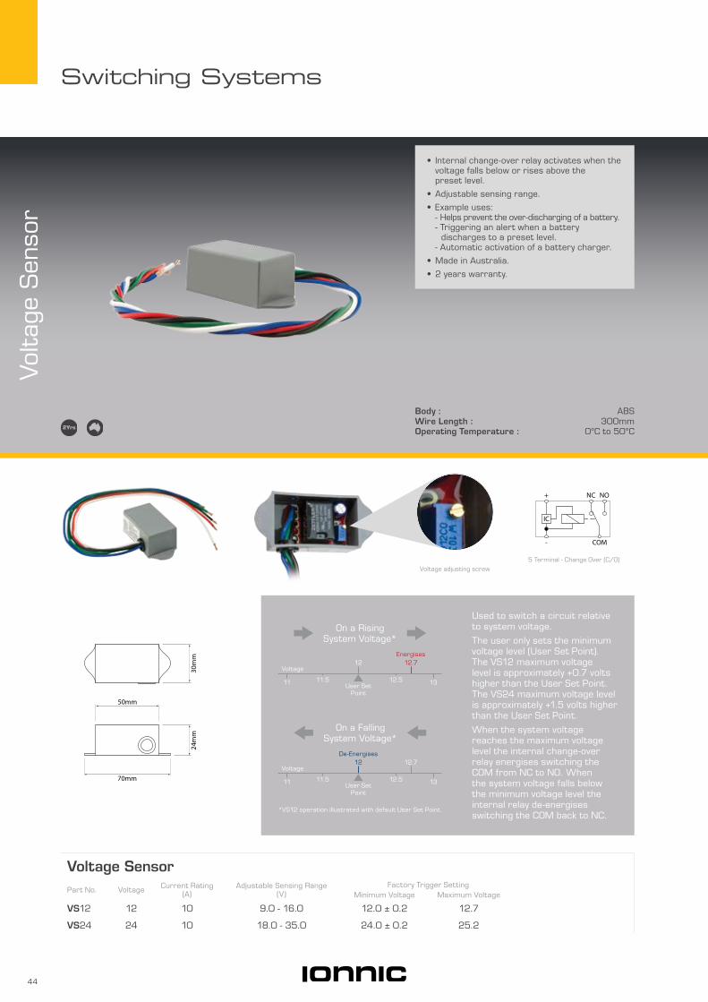
Body : ABSWire Length : 300mmOperating Temperature : 0 °C to 50°C
Voltag
e Sen
sor
Voltage SensorPart No. Voltage Current Rating
(A)Adjustable Sensing Range
(V)Factory Trigger Setting
Minimum Voltage Maximum Voltage
VS12 12 10 9.0 - 16.0 12.0 ± 0.2 12.7
VS24 24 10 18.0 - 35.0 24.0 ± 0.2 25.2
• Internal change-over relay activates when the voltage falls below or rises above the preset level.
• Adjustable sensing range.
• Example uses: - Helps prevent the over-discharging of a battery. - Triggering an alert when a battery discharges to a preset level. - Automatic activation of a battery charger.
• Made in Australia.
• 2 years warranty.
5 Terminal - Change Over (C/O)
COM
+ NONC
-
IC
Used to switch a circuit relative to system voltage.
The user only sets the minimum voltage level (User Set Point). The VS12 maximum voltage level is approximately +0.7 volts higher than the User Set Point. The VS24 maximum voltage level is approximately +1.5 volts higher than the User Set Point.
When the system voltage reaches the maximum voltage level the internal change-over relay energises switching the COM from NC to NO. When the system voltage falls below the minimum voltage level the internal relay de-energises switching the COM back to NC.
11 11.5 12.5 13
Voltage12.7
User Set Point
12De-Energises
On a Falling System Voltage*
On a Rising System Voltage*
Voltage12
User Set Point
12.7Energises
11 11.5 12.5 13
*VS12 operation illustrated with default User Set Point.
Voltage adjusting screw
50mm
30m
m24
mm
70mm

45
Switching Systems
Headlights O
n Units
Body : ABSWire Length : 200mmOperating Temperature : -40 °C to 70°C
• Designed to operate park & low beam lights any time vehicle ignition is on.
• Can be wired to disable control unit eg. hand brake switch, door switch.
• 10 seconds start up delay.
• Compact easy installation.
• Diagnostic LEDs.
• Available in positively and negatively switching models.
• Epoxy filled for enhanced moisture and vibration protection.
• 2 year warranty.
Headlights On UnitsPart No. Description
MS-LOR-12V Suits any negatively switched headlight
MS-LOP-12V Suits any positively switched headlight
MS-LOR-12V-KIT Suits Toyota Hi-Lux up to 2011 model. Supplied complete with plug-in harness
Installation on late model multiplexed vehicles must be performed by a qualified technician.
MS-LOR-12V-KIT - Easy InstallationMS-LOR-12V-KIT Headlights On Units are
exceptionally easy to install. The kit is supplied with plug-in harness to suit Toyota Hi-Lux.
Plugs directly into headlight harness
86mm
48m
m24
mm
95mm

46
Switching Systems
Han
d Bra
ke A
larm
Mod
ule • Can be adapted to any vehicle.
• Can be used as a general 2 stage alarm module.
• Designed to signal when hand brake is not engaged and vehicle door opens.
• Satisfies mine site requirements.
• 2 stage outputs.
• Compact easy installation.
• Suitable for positive and negatively switched vehicles/applications.
• Epoxy filled for enhanced moisture and vibration protection.
• Clean contacts.
• 2 year warranty.
Voltage : 12-24VCurrent Rating : 2 x 10A @ 12VBody : ABSWire Length : 150mmOperating Temperature : -40 °C to 70°C
Hand Brake Alarm ModulePart No. Description
MS-HB01 Suits any positive or negatively switched vehicle
86mm
48m
m24
mm
95mm
Epoxy filled for enhanced
moisture and vibration protection
Hand Brake Alarm OperationThe MS-HB01 Hand Brake Alarm Module is designed to satisfy the mine site requirement where all stationary vehicles must have the hand brake engaged.
The MS-HB01 does this by triggering alarms when a vehicle operator attempts to leave the vehicle by opening one or more of the doors without applying the hand brake.
The MS-HB01 unit is a 2 stage device.
Device deactivation will only occur when the hand brake is applied. Closing the door alone will not deactivate the unit.
Hand brake not engaged
Door opens
Stationary vehicle
5 seconds pass in stage 1
Stage 2 output triggers.
Stage 1 output triggers.

47
Switching Systems
• Selectable idle time cycle.
• LED indicators for visual warning.
• Multi-voltage.
• Environmentally sealed - IP65.
• Push & toggle switch kits available.
• Suitable for Energised To Run (ETR) systems.Energised To Stop (ETS) model available on request.
Voltage : 12-24VWeight : Controller Unit 255gEnclosure : ABSIgnition Output : 10AAuxiliary Output : 0.7AIngress Protection : IP65Approvals : CE, C-TickOperating Temperature : -40°C to 85°C
ION
NIC
Idle Timer
IONNIC Idle TimerPart No. Description
IT10452 Idle Timer kit - push button switch Kit contains: 1 x IT11450, 1 x IT10451
IT11452 Idle Timer kit - toggle switch Kit contains: 1 x IT11450, 1 x IT11451
IT11450 Idle Timer controller unit
IT10451 Harness with stainless steel push button switch & engraved label - 1.8m
IT11451 Harness with toggle switch, boot & pilot light - 1.8m
B657 Optional warning buzzer
79m
m
109mm 52mm
119mm 64mm
Ø 6.5mm
IT10450
B657
IT10451Illuminated push button switch (Red)
Engraved label
Illuminated pilot light (Amber)
IT11451

48
Switching Systems
Voltage : 12-24VCurrent Rating : 10A max.
• Multiple mounting options.
• Energise to run or stop models.
• Models with remote face.
• 5 Minute Fixed models feature 30A switching capacity via serviceable external relay.
• Multi-voltage.
• Vehicle specific pre-terminated models available on request, lead times apply.
Idle
Tim
ers
BES-925/ST-1
CST-515
BES-124/ST-4
Adjustable - Remote FacePart No. Outputs Energise to Time Intervals (min) Park Brake Override Description
BES-925/ST-1 1 Run 0.5, 1, 2, 3, 4, 5 Yes Non-electronic engine management
BES-925/ST-3 2* Run 0.5, 1, 2, 3, 4, 5 Yes Non-electronic engine management
BES-925/ST-4 1 Run 0.5, 1, 2, 3, 4, 5 Yes Electronic engine management
BES-925/ST-5 2 Run 0.5, 1, 2, 3, 4, 5 Yes Electronic engine management
CTR-M 1 Stop 0.5, 1, 2, 3, 4, 5 No Electronic engine management
* Second output used to isolate power to EDIC (shutdown) motor during idle period.
91mm
24m
m25
mm
130mm
29m
m
50mm

49
Switching Systems
Adjustable - X-SeriesPart No. Outputs Energise to Time Intervals Park Brake Override Description
BES-X104 1 Run 30 sec to 30 min Yes Suitable for both electronic & non-electronic
engine managementBES-X105 2 Run 30 sec to 30 min Yes
Fixed - Gauge MountPart No. Outputs Energise to Time Intervals (min) Park Brake Override Description
CST500 1 Run Fixed @ 5 No Relay driven output
CST515 1 Stop Fixed @ 5 No Relay driven output
AdjustablePart No. Outputs Energise to Time Intervals (min) Park Brake Override Description
BES-124/ST-1 1 Run 1, 3, 5 No Non-electronic engine management
BES-124/ST-2 2 Run 1, 3, 5 No Non-electronic engine management
BES-124/ST-4 1 Run 1, 3, 5 No Electronic engine management
Illuminated push button switch for manual Stop
override, mounts in supplied bracket
75mm
25m
m
54mm
33m
m
130mm
29m
m
50mm
52mm
58m
m
112mm

50
Switching Systems
WL601PS1
B657
BA16DS-RED
8015002
Voltage : 12-24VSensing Depth : WL601PS1 25mm
WL601P 35mmCurrent Rating : WL601LP 3A @ 12V
8015002 10A
• Visual & audible warning device for water/coolant level monitoring.
• LED indicator on modules.
• 7 second “slosh” delay preventing false triggering.
• Epoxy encapsulated modules.
• Brass sleeve or rubber multi-fit style probes available.
KitsPart No. Description
Kit ContentsProbe (x 1) Module (x 1) Pilot Lamp (x 1) Buzzer (x 1)
WL-1 10A Module with Threaded Probe WL601PS1 WL601LP BA16DS-RED B657
WL-2 10A Module with Multi-fit Probe WL601P WL601LP BA16DS-RED B657
WL-3 3A Module with Threaded Probe WL601PS1 8015002 BA16DS-RED B657
WL-4 3A Module with Multi-fit Probe WL601P 8015002 BA16DS-RED B657
All components available separately.
Low
Coo
lant
Ala
rm
8015002
B657 BA16DS-RED
WL601LP
WL601PWL601PS1
Ø 4
3mm
Ø 43mm
34m
m
6.3m
m
Ø 19mm
35m
m
16mm
4.8mm
10m
m
55m
m
16m
mØ
19m
m
6.3m
m
Ø 9.5mm
64m
m28m
m
Ø 2
5mm
Ø 1/4” NPT
27m
m42
mm
6.3m
m
72mm
87mm Ø 5.5mm
21m
m
66mm
37m
m
Ø 4.5mm
Catalogues
Related Documents