REGULATOR INFORMATION DISTRIBUTION S TEM (RIDS) ACCESSION NBR:8106190357 „DOC ~ DATE't 81/06/11 NOTARIZED: NO „DOCKET' FACIL>j50'"rr00 She'ar on Har r is Nuclear Power Planti Unf t is Car ol ina 05000400 AUTH ~ .NAME, AUTHOR AFF IL'I AT'ION CHIANGIiN.J. Car ol ina Power~.8 „. Light. Co. RECIP ~ NAME<, RECIPIENT AFFILZATION„ O'REILLY'S J'sP ~ Region 2i Atlanta'ffice" of the Director9 (81/03/01) SUBJECT<I Revision 1 to,810501„final deficiency rept r e weld symbol er'r or. s L misapplicatjon- of weld on Bergen Pager son pipe h'ange'r s,Revision 1 reflects editorial changes. DISTRIBUTION CDDE, S019$ .COPIES.RECEIVED>I.TR t1ENCl.i 'IZE:: TITLE'j= Construction Deficiency Repor t (10CFR50 ~ 55E) NOTES>: RECIPIENT'D CODE/NAMEt ACTION: A/D LICENSNG OQ LIC" BR'3- LA 06'NTERNAL: ASLBP/J ~ HARD EDO" L ST'AFF'9 HYD/GEO BR 22'. IE/EES MPA 20 OELD 2'1 QA BR ig STANDRDS DEV 21» COPIES LTTR ENCL< 1. 1 1 1 1 1 1 1 1 1 1- 1 1 1 1 1 1 RECIPIENT'D CODE/NAME'. LiC" BR" ¹3 BC 05 L'ICITRAgM ~ 07 D/DIR'UM FAC15 EQUIP'UAL BR11 ILE'$ LIC 'UAL» BR 1 g NRC'DR 02 REV 13 RE FILE'1 COPIES LTTR ENCL .1 1 1" 1 1 1 1 1 1 1 1 1 1 1 1 1 EXTERNALR ACRS NSIC 16 08 16 16 1 1 LPDR 03 TOTAL NUMBER OF COPIES'EQUIRED L1TTR 37 ENCL 37

Welcome message from author
This document is posted to help you gain knowledge. Please leave a comment to let me know what you think about it! Share it to your friends and learn new things together.
Transcript

REGULATOR INFORMATION DISTRIBUTION S TEM (RIDS)
ACCESSION NBR:8106190357 „DOC ~ DATE't 81/06/11 NOTARIZED: NO „DOCKET'FACIL>j50'"rr00 She'ar on Har r is Nuclear Power Planti Unf t is Car ol ina 05000400
AUTH~.NAME, AUTHOR AFF IL'IAT'IONCHIANGIiN.J. Car ol ina Power~.8 „. Light. Co.
RECIP ~ NAME<, RECIPIENT AFFILZATION„O'REILLY'S J'sP ~ Region 2i Atlanta'ffice" of the Director9 (81/03/01)
SUBJECT<I Revision 1 to,810501„final deficiency rept r e weld symboler'r or. s L misapplicatjon- of weld on Bergen Pager son pipeh'ange'r s,Revision 1 reflects editorial changes.
DISTRIBUTION CDDE, S019$ .COPIES.RECEIVED>I.TR t1ENCl.i 'IZE::TITLE'j= Construction Deficiency Repor t (10CFR50 ~ 55E)
NOTES>:
RECIPIENT'D
CODE/NAMEtACTION: A/D LICENSNG OQ
LIC" BR'3- LA
06'NTERNAL:ASLBP/J ~ HARDEDO" L ST'AFF'9HYD/GEO BR 22'.IE/EESMPA 20OELD 2'1QA BR igSTANDRDS DEV 21»
COPIESLTTR ENCL<
1.1 1
1
1 1
1 1
1 1
1- 1
1
1 1
1 1
RECIPIENT'D
CODE/NAME'.LiC" BR" ¹3 BC 05L'ICITRAgM ~ 07
D/DIR'UM FAC15EQUIP'UAL BR11ILE'$LIC 'UAL» BR 1 gNRC'DR 02
REV 13RE FILE'1
COPIESLTTR ENCL
.1 11"
1 1
1
1 1
1 1
1 1
1 1
1 1
EXTERNALR ACRSNSIC
1608
16 161 1
LPDR 03
TOTAL NUMBER OF COPIES'EQUIRED L1TTR 37 ENCL 37

0li
'
~ E
U
'
II
It
I tt t'1i
t

FORM 21 100 M
Pile: SH N-2/18Item 48
CPSCarollrla Power & Light Company
Raleigh, N. C. 27602
June 11, 1981
Mr. James P. O'ReillyUnited States Nuclear Regulatory CommissionRegion II101 Marietta Street, NorthwestAtlanta, Georgia 30303
SHEARON HARRIS NUCLEAR POWER PLANTUNIT 1
DOCKET NO. 50-400MELD SYMBOL ERRORS AND MISAPPLICATION
OF WELD OH BERGEN-PATERSONPIPE HANGERS
HRC IHPRACTION 400/80-22-01
..efK I/(g'>~test-
-~lU.g,
Dear Mr. O'Reilly:
In accordance with 10CPR50.55(e), a final report on the subject deficiencywas forwarded to you on May 1, 1981. Attached is Revision 1 to thatreport reflecting certain editorial changes. Pages revised are:
i)ii)
iu.)iv)v)
'i)
Page 4Exhibit No. 2,Exhibit No. 3,Exhibit Ho. 5Exhibit No. 7,Exhibit No. 8,
pages 1, 4pages 7, 8, 15
pages 2, 3, 4, 5, 6, 7
pages 1, 2
Xf you have any questions regarding the above, please do not hesitate tocontact me.
NJC/IRt (7239)Attachment
cc: Mr. G. Maxwell M/AMr. V. Stello (2) W/A ~
Yours very truly,
Original Signed By
N. 3. ChiangiH. J. Chiangi —Manager
Engineering 6 ConstructionQuality Assurance/Quality Control
'Boll5
i/j
"~
I11
y
V

CAROLINA POWER 6 LIGHT COMPANYSHEARON HARRIS NUCLEAR POWER PLANT
UNIT NO. 1
WELD SYMBOL ERRORS ANDMISAPPLICATION OF WELD ON
BERGEN-PATERSON PIPE HANGERS
FINAL REPORT
PREPARED BY:CAROLINA POWER & LIGHT COMPANY
REVISION 1

INTRODUCTION
Seismic Class I Bergen-Paterson pipe hangers are detailed on design drawings whichspecify=location, geometry, material and joint welding requirements. Welding pro-cesses, filler metal, etc. are described in Procedure MP-08 — "General WeldingProcedure for Structural Steel (Seismic and Non-Seismic) and Hangers". Weld in-spection requirements, are specified in Site Specification No. 034, "NondestructiveExamination, Visual Inspection and Testing Requirements for Code Class 1, 2, 3,Balance-of-Plant Piping Systems, Seismic and Non-Seismic Structures for PermanentPlant Construction".
Work Procedure WP-110 — "Installation of Safety Related (Seismic Class I) PipeHangers and Thermally Analyzed Pipe Hangers" provides instruction to the craftregarding the installation of the pipe hangers.
Weld types most often used in the installation of pipe hangers are the fillet weldand the flare-bevel weld. Occasionally, a groove weld is used.
DESCRIPTION
On September 3, 1980, the Resident NRC Inspector identified a problem with unclearand incorrect weld symbols on Bergen-Paterson Seismic Class I pipe hanger
drawings'lso,field inspection by the Resident NRC Inspector identified situations where theweld actually applied 'on the pipe hangers differed from .that required by the designdrawing; i.e., over-welding (more weld length than required) and over-sized fillets.The problem identified above prompted an immediate investigation of other pipehanger drawings and reinspection of selected completed and inspected pipe hangers.
1 ~ Approximately 1,200 pipe hanger drawings (representing hangers whoseinstallation was either in progress or complete) were reviewed forerrors and clarity. The results were many incorrect and unclear weldsymbols.
2. Approximately 100 installed pipe hangers were reinspected by QAinspectors. The results were: 1) Welds larger and smaller thanspecified by the drawings; 2) fillet welds applied where fullpenetration groove welds were specified; 3) no evidence ofcomplete penetration on some full penetration groove welds renderingthem questionable; and, 4) welds being applied on more sides orfewer sides than specified.
SAFETY IMPLICATIONS
Those hangers welded with smaller fillets, fewer sides than specified (under-welding) and improper welds, pose a potential safety concern in that thesehangers, as installed, may not be capable of supporting their design loads ormeeting their design margins.
Those hangers welded on more sides than .specified (over-welding) pose a potentialsafety concern in that some hangers require flexibilityat specific joints inorder to not transmit large moment loads to the embedded steel support plates.Flexibility is obtained by no welding or minimal welding on certain sides of thejoint.

Those hanger drawings with incorrect and unclear weld symbols pose a potentialsafety concern in that, if left uncorrected, would result in incorrect or ques-tionable translation of design requirements in the installation and inspectionprocess.
This item is considered reportable due to design drawing errors by Bergen-Paterson, failure to fabricate in accordance with design drawings by the craftpersonnel and failure of QA to translate design requirements to insure properconstruction.
CORRECTIVE ACTION
The cause of the problem is three-fold: 1) Design drawing with incorrect orunclear weld details were provided by the vendor and, passing through all checkingstages, were issued to the field uncorrected. 2) Field personnel failed to weldthe pipe hangers, in accordance with the design drawings and/or made welds whendetails were missing or unclear. 3) QA failed to insure that welds were appliedin accordance with design drawings and/or that welds applied were clearly indicatedon design drawings.
To prevent future occurrences, the following actions were taken:
1. The Site Hechanical and Welding Units are now reviewing pipe hangerdesign drawings for missing, unclear, and incorrect weld symbolsprior to issuance to the field. Drawings with problems are reportedto Ebasco/Bergen-Paterson for correction via pipe hanger problem memos(PHPs) written by the Site mechanical Unit. Ebasco discussed thedesign drawing problems with Bergen-Paterson who identified the problemto their design personnel. Bergen-Paterson agreed to revise theirreview procedures to insure that design drawings show proper weldsymbols- All drawings being issued from Bergen's three design officesare now routed through the Hempstead Office to provide more consistentreview by Bergen engineering personnel. A review of 37 hanger designdrawings issued by Bergen-Paterson since January 1, 1981 revealed only3 design drawings with weld symbol
problems'.
Weld symbol identification training classes were conducted by SiteWelding and mechanical Engineers. Superintendents, general foremen,foremen, and welders of pipe and pipe hangers attended along withconstruction inspectors, QA inspectors, and mechanical unit personnelinvolved with pipe hangers. In addition to instruction on weld symbolidentification, emphasis was given on the importance of welding the pipehanger exactly as the design drawing requires. In those instances wherethis is not possible, due to physical limitations or drawing errors, thehanger drawing is to be returned to the Site Mechanical Unit. Analysisof QA inspection reports on welding performed since the training classesindicate that corrective action has been effective. For example, a testcase of hangers welded and inspected since the training yielded theresults shown in Exhibit l.
3 ~ In addition to attending the weld symbol identification classes refer-enced in 2. above, QA personnel attended similar classes given withinthe QA organization in order to strengthen weld symbol recognition.skills and to emphasize the necessity for inspections to be in strictaccordance with drawing details. QA personnel were. instructed to reportincorrect design drawings to the Site Mechanical Engineering Unit.

P»\
Due to the safety implications detailed earlier in this report, a program ofcorrective action was required for t'e hangers previously installed or partiallyinstalled. This corrective action was a 100K QA reinspection of all seismicpipe hangers that had ever been issued to the craft for work that were stillactive. Some pipe hangers were deleted by Ebasco or Bergen-Paterson and wereomitted from the reinspection scope. This corrective action also included 100%in-house review of these hangers'esign drawings. The results of the reinspec-tion and in-house review of these hanger drawings and the resolutions of theproblems identified are detailed on Exhibit No. 2. The hangers involved areshown on Exhibit No ~ 3 ~
~p
As a result of our investigations of the welding problems of pipe hangers, we beganto investigate other areas of welding activity for similar problems. The followingreport details our investigation and corrective and preventive actions on the weldingof HVAC duct hangers and electrical cable tray and conduit hangers.
HVAC, CABLE TRAY AND CONDUIT SEISMIC SUPPORT HANGERS
DESCRIPTION
To begin the investigation of potential welding problems, several HVAC and elec-trical hanger drawings were reviewed. It was noted that numerous inconsistenciesand unclear welding symbols and details existed on the design drawings. The dis-covery of clarity problems on the design drawings prompted a field spot check onseveral HVAC and electrical hangers to reveal any potential weld problems similarto the pipe hangers. The results of the spot check revealed: a) welds larger andsmaller than design; b) welds being applied on more sides than required; c) weldsimproperly located; d) welds over holes or gaps between embedded plates; e) missingwelds; f) missing welder's symbol.
Welds for HVAC, cable tray and conduit hangers were detailed on Ebasco Servicesdesign drawings as well as erection drawings furnished by the hanger vendor,Peden Steel. Welding processes are described in Procedure MP-08 — "GeneralWelding Procedure for Structural Steel (Seismic and Non-Seismic) and Hangers"and weld inspection requirements are specified in Site Specification No ~ 034
'orkProcedure WP-400 — "Installation of HVAC Seismic Category I Support" andWP-203 — "Installation of Seismic Class I Electrical Cable Tray, Tray Support,Conduit, Conduit Support, Boxes and Box Support", provides instructions to thecraft regarding hanger installation.
The weld type most frequently found in the design of electrical and HVAC hangersis a fillet weld. Flare-bevel welds ar'e used on the attachment of unistrut supportsand combination supports (supports that carry both HVAC duct and cable tray).
SAFETY IMPLICATIONS
Those hangers welded with smaller fillets, fewer sides and missing welds pose apotential safety concern in that if the condition was left uncorrected, the hangersmay not be capable of supporting their design loads.
Consideration for flexibilitywas not a concern as HVAC anchor type hangers arerigidly braced to prevent movement and HVAC guide type hangers are rigidly bracedand designed to allow for thermal movement of the duct in one plane only. Flexi-bility was also of no concern for electrical hangers since they are of rigid design.

(

Cu4UKCTIVE ACTION\
The occurrence of HVAC and electrical hanger problems were attributed to 1) failureof the A/E or the vendor to supply correct and clear'esign drawings; 2) failure ofcraft personnel to properly read and interpret the design drawings, and to bring tothe attention of on-site engineering unclear information or questions; and 3) fail-ure of QA personnel to interpret and to inspect welds to the design drawing.
To prevent future occurrences, the following actions'ere taken:
1. The A/E was notified and requested to make the design drawing correctionsand to review additional design drawings to evaluate their present methodof indicating design welds to welded cohnections.
2. Additional sessions of the weld symbol identification training classes wereconducted by site welding and mechanical engineers. Craft supervisors,craft personnel, QA inspectors and construction inspectors involved withHVAC and electrical hangers attended. The subjects discussed were the sameas those addressed in the classes conducted for pipe hanger personnel.
3. MP-400 — "Installation of HVAC Seismic Category I Supports", and WF-203—"Electrical Cable Tray, Cable Tray Support, Conduit, Conduit Support, Boxesand Box Support", have been revised to include hold points during theerection and welding processes. The procedures also prohibit the craftfrom proceeding with work when problems arise during the erection processwithout resolution from the discipline engineer.
4. As a result of the problems identified during the field spot check of HVACand electrical hangers, QA welding inspectors were assigned to reinspectall of the HVAC and electrical hangers that had been previously accepted.Approximately 100 HVAC and * 300 cable tray and conduit hangers werereinspected for field errors and discrepancies. The results revealedthat approximately 95% of the hangers reinspected had nonconformingconditions or deviations from the design drawings.
The results of the 100% reinspection are shown on Exhibits 4 and 5. A list of theaffected HVAC and electrical hangers are shown on Exhibits 6 and 7 respectively.fields were rejected based on the same criteria as applied to pipe hangers.
The rejected hangers were resolved by the following means:
1. Hangers with missing and undersized welds were rewelded in accordancewith design documents with work controlled through the use of a reworkpackage in which QA inspection and acceptance of the rework was documented.
2. Hangers that were missing welder's stencils were corrected in like manneras the pipe hangers.
3. Hangers with arc strikes, spatter, cold lap, undercut, slag and porositywere reworked with controls similar to item l. and reinspected by QA.
4. Hangers with discrepancies such as oversized welds, welds over holes andgaps, improper weld locations, improper weld lengths, improper hangerfit-up and design drawing problems were dispositioned by engineeringevaluations with permanent waivers (PMs) or field change requests (FCRs).See Exhibit 8 for listing of applicable FCRs and PMs.
* Rev. 1, 05/27/81


EXHIBIT NO. 1
Analysis of QA Inspection Reports-Test Case of 63 Pipe HangersNelded After Nelder Training Class
63 hangers in test case
55 hangers acceptable; 87.3%
8 hangers rejectable; 12.7%
Rejected Hangers:
1. A-3«236-1-PD-H-1266Rejected 3/20/81 Overlap, lack of fusion
2. A-2-236-1-PD-H-1519Rejected 1/9/81 Convexity; Accepted 1/20/81
3. A-2-236-1-PD-H-1526Rejected 3/24/81
4. A-2-236-1-PD-H-1550Rejected 3/24/81
5. T-2»261«1-F11«H-30Rejected 3/25/81
6. T-2-261-1-FH-H-31Rejected 3/25/81
7. F 1 236 1 SF H 463Rejected 3/28/81
8. 01-6-236-1-WG-H-1706Rejected 3/28/81Rejected 4/4/81
Oversized; Accepted 1/20/81
Overlap, weld splatter, are strikes
Arc Strikes, missing welds, lack of fusion
Arc Strikes, undercut, overlap, undersize,missing welds
Undercut; Accepted 4/3/81
Slag, overlap, weld splatters

EXHIBIT NO. 2
Results of 100Z In-House Review ofPipe Hanger Design Drawings and
Reinspection of Pipe Hanger Welding
1 ~ Drawing Review
1786 hanger design drawings were reviewed
PHPs (pipe hanger problems) were written to report to Ebasco/
Bergen -Paterson the problems identified. Problems were ofthree groups:
a) Unclear symbols
b) Missing symbols
c) Incorrect symbols
Most PHPs reported problems with one hanger drawing only. A
few reported problems with more than one hanger drawing. The
PHP resulted in the issuance of a new drawing 'revision withcorrections to the problems.
2. Reinspection1786 pipe hangers issued for QA reinspection
701 determined to be not installed487 pipe hangers found acceptable
598 pipe hangers rejected
Pipe hangers were rejected when the followinga. missing welder's symbols
b. oversized welds (greater than 1/8")c. undersized welds
d. weld type applied not the same asdrawing
e. overweld
missing welds
g. incomplete penetration of groovewelds
h. welder's stencil in heat affectedzones
conditions were found:
i. welding over holes/gapsin embeds
j. slagk. porosity
l. undercutm. overlapn. arc strikes
o. weld splatter
* Rev. 1, 05/27/81
'4c.
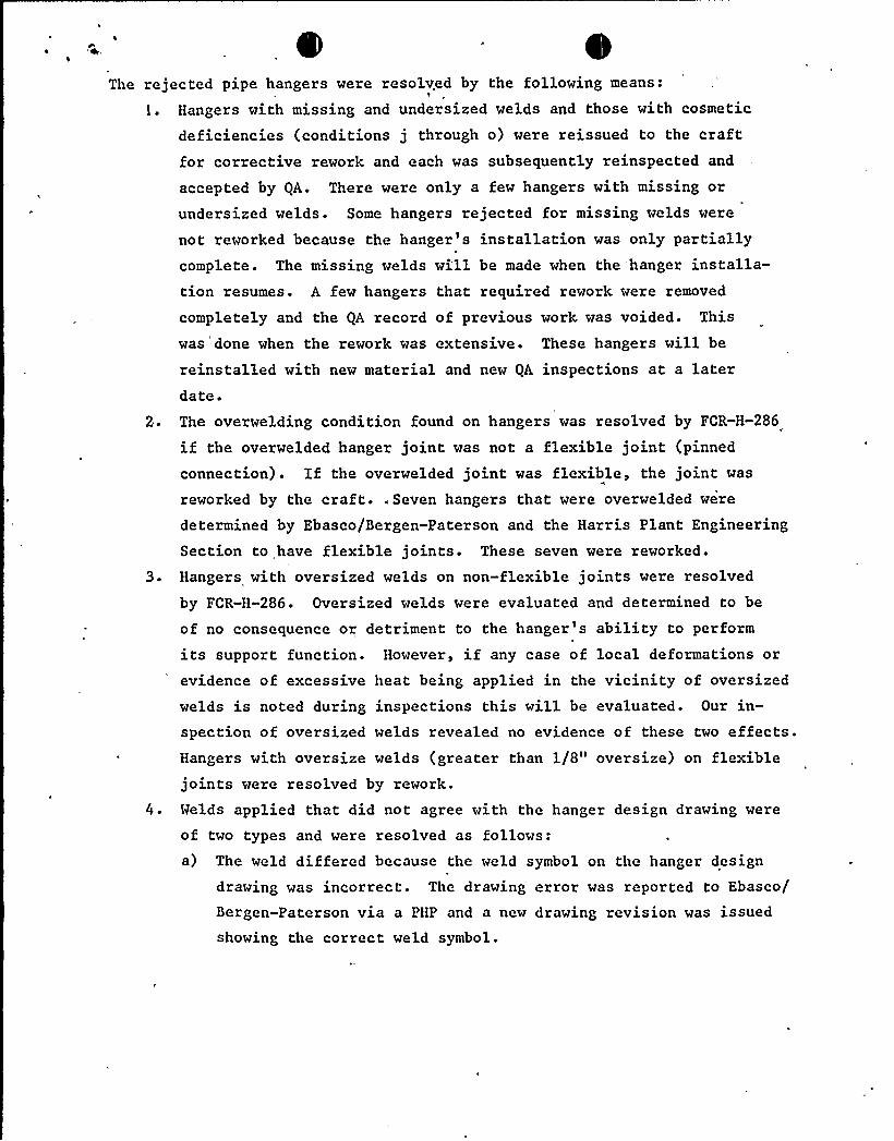
The rejected pipe hangers were resolved by the following means:1
1 ~ Hangers with missing and undersized welds and those with cosmetic
deficiencies (conditions j through o) were reissued to the craftfor corrective rework and each was subsequently reinspected and
accepted by QA. There were only a few hangers with missing or
undersized welds. Some hangers rejected for missing welds were
not reworked because the hanger's installation was only partiallycomplete. The missing welds wi'll be made when the hanger installa-tion resumes. A few hangers that required rework were removed
completely and the QA record of previous work was voided. Thiswas'done when the rework was extensive. These hangers will be
reinstalled with new material and new QA inspections at a laterdate.
2. The overwelding condition found on hangers was resolved by FCR-H-286
if the overwelded hanger joint was not a flexible joint (pinned
connection) ~ If the overwelded joint was flexible, the joint was
reworked by the craft. „Seven hangers that were overwelded were
determined by Ebasco/Bergen-Paterson and the Harris Plant EngineeringSection to have flexible joints'hese seven were reworked.
3 ~ Hangers with oversized welds on non-flexible joints were resolved
by FCR-H-286. Oversized welds were evaluated and determined to be
of no consequence or detriment to the hanger's ability to perform
its support function. However, if any case of local deformations or
evidence of excessive heat being applied in the vicinity of oversized
welds is noted during inspections this will be evaluated. Our in-spection of oversized welds revealed no evidence of these two effects.Hangers with oversize welds (greater than l/8" oversize) on flexiblejoints were resolved by rework.
4 . Welds applied that did not agree with the hanger design drawing were
of two types and were resolved as follows:a) The weld differed because the weld symbol on the hanger design
drawing was incorrect. The drawing error was reported to Ebasco/
Bergen-Paterson via a PHP and a new drawing revision was issued
showing the correct weld symbol.

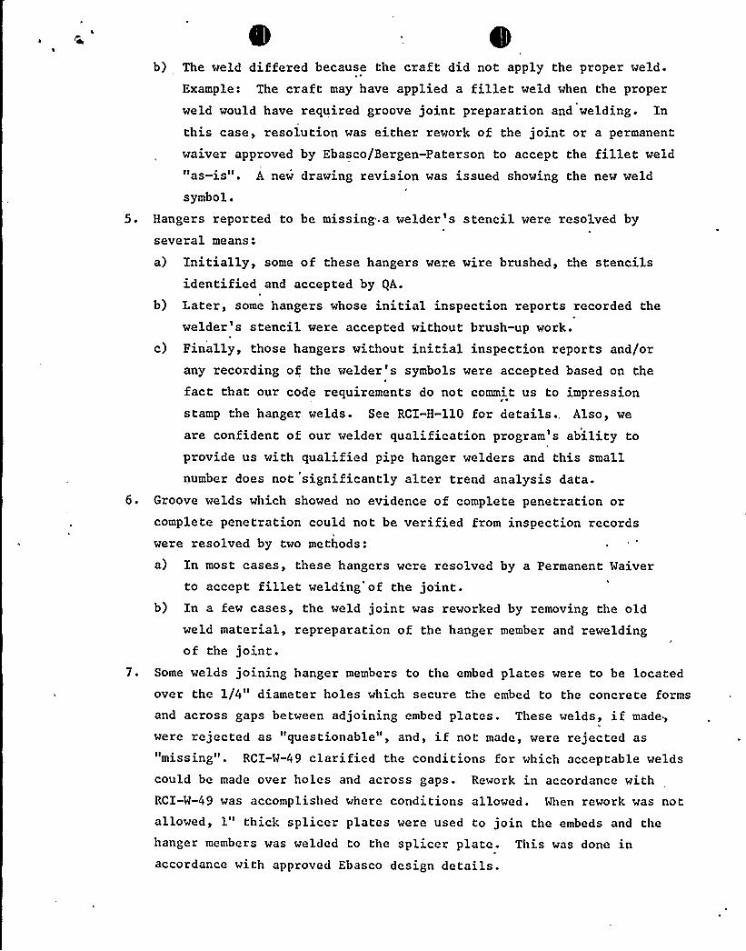
b) The weld differed because the craft did not apply the proper weld.
Example: The craft may have applied a fillet weld when the properweld would have required groove joint preparation and welding. Inthis case, resolution was either rework of the joint or a permanent
waiver approved by Ebasco/Bergen-Paterson to accept the fillet weld"as-is". A new drawing revision was issued showing the new weld
symbol.
5. Hangers reported to be missing a welder's stencil were resolved by
several means:
a) Initially, some of these hangers were wire brushed, the stencilsidentified and accepted by QA.
b) Later, some hangers whose initial inspection reports recorded thewelder's stencil were accepted without brush-up work.
c) Finally, those hangers without initial inspection reports and/orany recording of the welder's symbols were accepted based on thefact that our code requirements do not commit us to impressionstamp the hanger welds. See RCI-H-110 for details., Also, we
are confident of our welder qualification program's ability toprovide us with qualified pipe hanger welders and this smallnumber does not significantly alter trend analysis data.
6. Groove welds which showed no evidence of complete penetration orcomplete penetration could not be verified from inspection recordswere resolved by two methods:
a) In most cases, these hangers were resolved by a Permanent Waiverto accept fillet welding'of the joint.
b) In a few cases, the weld joint was reworked by removing the oldweld material, repreparation of the hanger member and reweldingof the joint.
7. Some welds joining hanger members to the embed plates were to be locatedover the 1/4" diameter holes which secure the embed to the concrete formsand across gaps between adjoining embed plates. These welds, if made,
were rejected as "questionable", and, if not made, were rejected as
"missing". RCI-W-49 clarified the conditions for which acceptable welds
could be made over holes and across gaps. Rework in accordance withRCI-W-49 was accomplished where conditions allowed. When rework was notallowed, 1" thick splicer plates were used to join the embeds and thehanger members was welded to the splicer plate. This was done inaccordance with approved Ebasco design details.

'8. Welder's stencil ocated in the heat affected zo were repaired by
removing the stencils and relocating them outside the heat affectedzones. The removing of the stencils was accomplished by grinding.
9. A total of *258 hangers were reworked in the instances described above.
* Rev. l; 05/27/Sl
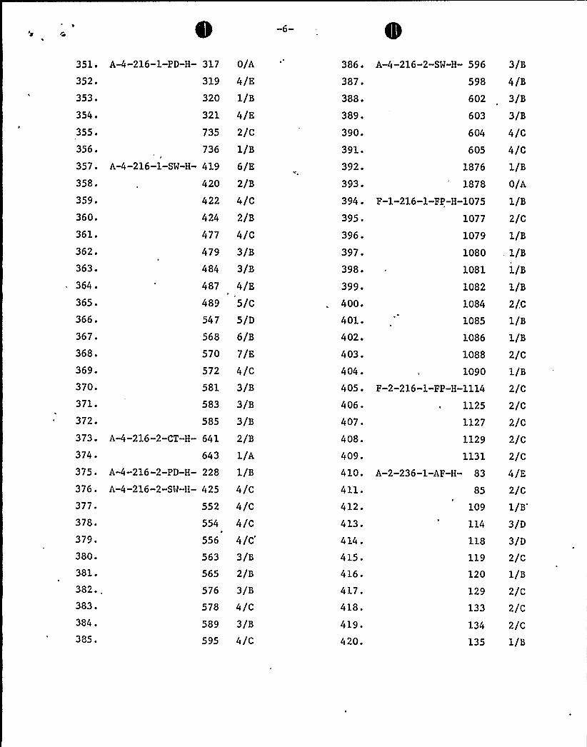
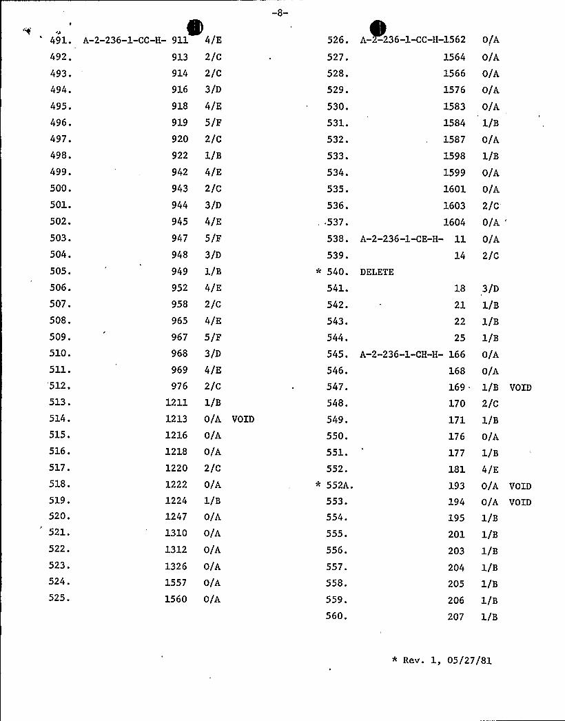
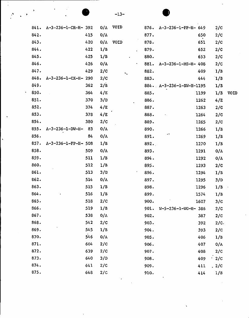
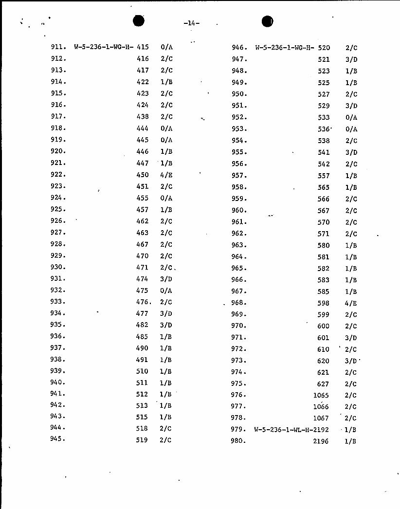
EXHIBIT NO. 3
Sheets 1 thru 16
Listing of installed Bergen-Paterson Hangersthat received a QA field reinspection. Hangerswith "Void" listed were deleted by Bergen-Patersonafter the QA reinspection.

1. A-1-190-1-CC-H-
2 ~
3 ~
4 ~
5 ~
6 ~
7 ~
8 ~
9 ~
10.
12.
13 ~
14 ~
15 ~
16.
17'8
'9. A-1-190-1-CH-H-
20.
21'2
'3.
24 '-1-190-1-CT-H-25 ~
26 ~
27-
28 ~
29'0.
31.
32.
33 ~
34.
35.
600
602
612
635
636
641
644
1148
1153
1156
1157
1158
s/o3/c4/o2/B
3/D
5/E
4/E
8/X
4/E
S/F
2/C
1269
1271
1272
1277
1283
70
71
72
91
92
224
227
247
269
270
277
278
279
280
282
283
298
2/B
2/B
2/B
2/B
3/c4/E1/B
2/C
1/B
1/B
6/cs/c5/o6/cs/c8/E
6/o5/c6/o7/o6/o8/F
1159 5/F
36. A-1-190-1-CT-H-
37'8
'9
'0.
41 ~
42.
43'4.
45 ~
46'7.
48 ~
49'.
50.
51'2
'3
'4
~
55'6
'7
'8.
59'0.
61.
62.
63.
64 ~
65'6
'7
~
68'9
'0
'99
300
304
309
312
331
337
338
358
359
360
423
424
427
430
432
433
434
438
440
442
446
447
449
451
5/D
4/c2/B
7/D
8/E
7/o4/B
8/E
6/os/c8/F
4/c6/E
4/c3/B
3/B
4/c6/E
3/B
4/c3/B
3/B
3/B
3/B
3/B
460
462
464
466
468
469
470
471
472
8/F
6/D
7/E
s/c5/c5/c6/D
6/D
8/F
459 10/H

71. A-1-190-1-CT-H- 474
72'3
~
74.
75 ~
76 ~
77'8.
79'0.
476
477
479
480
481
482
483
486
797
88.
89.
90.
91'2
'3.
94 ~
95 ~
96 ~
97'8
'9
'00.
101.
102.
103.
104 .
105.
10
13
14
29
35
37
40
42
43
44
45
46
48
49
50
51
52
81. A-1-190-1-CX-H- 96
82. A-1-190-1-FP-H- 256
83. A-1-190-1-PD-H-
84.
85 ~
86.
87.
6/D
s/c6/D
5/c6/D
s/c6/D
s/c6/D
0/A
2/C
1/B
2/c2/c1/B
1/B
1/B
2/c4/E
1/B
1/B
2/c2/c0/A2/c2/c4/F2/c2/C
2/C
2/c0/A
2/C
1/B
1/B
106- A-1-190-1-PD-H-
107'08.
109.
110.
112.
113.
114 ~
115.
116 ~
117.
118.
119.
120.
121.
122.
123.
124 ~
125.
126.
127.
128.
129.
130.
131.
132.
133.
134.
135-
136.
137.
138.
139.
140.
53
54
55
56
59
1/B
1/B
1/B
1/B
2/C
65
67
69
71
72
73
74
75
76
77
78
81
82
83
84
86
87
88
89
91
92
97
98
102
103
104
105
107
109
1/B
1/B
2/c3/D
1/B
3/D
3/D
1/B
2/C
1/B
2/c1/B
2/C
1/B
3/D
4/E
1/B
2/C
1/B
0/A
1/B
1/B
1/B'/c
2/c2/C
1/B
4/E
0/A
63 1/B

141 ~ A-1-190-1-PD-H-
142 ~
143.
144.
145 '-1-190-1-RH-H-146 ~
147.
148 ~
149 ~
150.
111
112
113
115
15
16
17
25
26
33
2/C
2/C
1/B
1/B7/D
4/D
3/B
7/E
5/D
5/c
176. A-3-216-1-PD-H-
177.
178.
179.180.
181.
182.
183.
184 ~
185 ~
341
345
352
367368
369
370
371
489
490
4/E
1/B
1/B
1/B0/A
1/B
0/A
2/C
1/B
1/B151
'52.
153'54.
155.
156.
157 ~
158.
159 ~
160. A-3-216-1-CT-H-
161.
162.
163.
164 .
165.
166.
167.
168.
169.
170.
171.
172.
173. A-3-216-1-FP-H-174.
175. A-3-216-1-PD-H-
35 6/D
57
60
62
6/B
7/D
7/c63 13/J64
208
209
211
213
214
216
249
250
252
253
254
257
274
246
270
339
7/D
3/c0/A
0/A
0/A
0/A
0/A
3/D
1/B
3/c2/B
2/B
3/c5/E
1/B
1/B
3/D
. 45 7/E
53 0/A
55 6/D
186.
187.
188.
189'90.
191.
192.
193.
194 ~
195 ~
196.
197.
198'99.
200.
201.
202.
203.
204 ~
205 .
206.
207 ~
208.
209.
210.
491
492
493
494
495
496
565
567
569
570
571
572
576
577
578
615
616
617
619
620
621
622
623
627
628
0/A
1/B
1/B
2/c1/B
3/D
1/B
2/c0/A
0/A
2/C
1/B
2/C
0/A
1/B
0/A
1/B
0/A
4/E
5/F0/A
0/A. 1/B
O/A
0/A


211. A-'3-216-1-PD-H- 629 1/s 246. A-3-216-1-SM-H- 362 4/c212.
213.
214 .
215.
216.
217.
218.
219.
220.
221.
222.
223.
224.
225.
226.
227.
228.
229.
230.
231.
232.
233.
234 .
235.
236.
237.
238.
239.
240.
241.
242.
243.
630
631
633
634
635
636
637
639
640
641
642
643
645
647
648
649
650
652
689
690
691
692
693
694
695
696
697
1132
1134
1135
2086
2092
244 . A-3-216-1-SM-H- 359245. 360
1/s4/E
3/D
3/D
1/s1/s4/E
1/B
1/s1/s0/A
4/E
4/E
2/c2/c1/s2/c4/E
0/A
1/s0/A
1/S
O/A
1/S
1/S
O/A
4/E
3/D
2/c3/D
1/B
O/A
2/B
2/B
247 ~
248 ~
249.
250.
251.
252 ~
253 ~
254.
255.
256 ~
257.
258.
259.
260.
261'62.
263.
264.
265.
266.
267.
268.
269.
270.
271.
2?2
273.
274.
275.
276.
277.
278.
279.
280
'70
372
374
378
379
380
381
382
384
385
386
387
388
391
392
393
394
398
400
404
406
410
412
448
452
454
455
456
458
459
460
5
3/c4/B
4/s3/c3/C
3/c3/c3/c3/c3/c3/c3/c3/c3/c3/c3/cO/A
O/A
0/A
1/s1/S
2/s3/c.3/c2/s2/s3/c2/B
2/B
3/C
'364 2/B
366 '/B368 2/B

282.
283.
284.
285.
286.
287'88.
289.
290.
291.
292.
293.
294 ~
295.
296.
297.
298.
299.
300.
301.
302.
303.
304.
305 .
306.
307.
308.
309.
310.
311.
312.
313.
314 .
315.
463
464
466
467
468
471
475
517
519
521
528
529
530
531
532
533
534
535
536
537
538
539
'40545
608
893
895
897
899
901
902
903
904
905
281. A-3-216'-1-SW-H- 462 2/B
2/B
3/C
2/B
2/B
2/B
3/C
3/C
3/C
4/D
3/C
6/F
4/D
3/C
4/C
4/c4/C
4/C
4/C
4/c4/C
4/c5/D
2/B
4/D
3/C
1/B
2/C
1/B
1/B
1/B
2/C
1/B
1/B
1/B
316 ~
317.
318.
319.
320.
321'22.
323.
324 ~
325 ~
326.
327.
328.
329.
330.
331.
332.
333.
334 .
335.
336.
337.
338.
339.
340.
341.
342.
343 ~
344 ~
345 ~
346 ~
347.
348.
349.
350.
A-3-216-1-SW-H-
A-4-216-1-CT-H-
A-4-216-1-PD-H-
906
907
908
927
928
929
930
932
1/B
1/B
1/B
1/B
1/B
1/B
1/B
1/B
934 1/B
935
936
1/B
1/B
943 '/C947 1/B
952 2/C
953 2/C
959
960
1/B
1/B
978 2/C
979 4/E
982
991
1176
1177
1181
1183
1184
1186
1201
1203
4/E
2/C
3/D
1/B
1/B
1/B
1/B
1/B
3/D
2/C
5/E259
260 4/D
261 4/D
262
263
307
4/D
2/B
2/C

351.
352'53
'54.
355.
356.
357.
358.
359.
360.
361 ~
362.
363.
364.
365.
366.
367'68.
A-4-216-1-PD-H-
A-4-216-1-SM-H-
317
319
320
321
735
736
419
420
422
424
477
479
484
487
489
547
568
570
0/A
4/E
1/B
4/E
2/C
1/B
6/E
2/B
4/C
2/B
4/C
3/B
3/B
4/E
5/C
5/D
6/B
7/E
386'87.
388.
389.
390.
391.
392.
393 ~
394 ~
395 ~
396.
397.
398.
399.
400.
401-
402.
403.
A-4-216-2-SW-H- 596
598
602
603
604
605
1876
1878
F-1-216-1-FP-H-1075
1077
1079
1080
1081
1082
1084
1085
1086
1088
3/B
4/B
3/B
3/B
4/c4/C
1/B
0/A
1/B
2/C
1/B
1/B
1/B
1/B
2/C
1/B
1/B
2/C369.
370.
371.
372.
373.
374.
375.
376.
377.
378.
379.
380.
381.
382.,383.
384.
385.
AA-216-2-CT-H-
A-4-216-2-PD-H-
A-4-216-2-SH-H-
572
581
583
585
641
643
228
425
552
4/c3/B
3/B
3/B
2/B
1/A
1/B
4/C
4/c
563
565
576
578
589
595
3/B
2/B
3/B
4/C
3/B
4/c
554 4/C
556
4/C'04
.
405 ~
406 ~
407.
408.
409'10.
411.
412.
413.
414 .
415.
416.
417.
418.
419.
420.
A-2-236-1-AF-H- 83
85
109
114
118
119
120
129
133
134
135
1090
F-2-216-1-FP-H-1114
1125
1127
1129
1131
1/B
2/C
2/C
2/C
2/C
2/C
4/E
2/C
1/B
3/D
3/D
2/C
1/B
2/C
2/C
2/C
1/B

A-2-236-1-AF-H-
A-2-236-1-BD-H-
138
144
131
132
139
142
A-2-236-1-CC-H- 89
90
91
92
93
94
95
97
98
99
100
101
102
105
107
110
ill'112
113
A-2-236-1-BR-H- 467
468
1553
1554
1555
1556
1557
1558
1559
1560
2/C
3/D
1/B
1/B
2/c1/B
0/A
0/A
O/A
O/A
0/A
O/A
O/A
O/A
O/A
O/A
2/c1/B
2/c3/D
5/F2/C
2/c2/C
2/C
3/D
6/G
4/E
5/F3/D
2/C
2/c1/B
2/C
1/B
456.
457.
458.
459.
460.
461.
462
463.
464 ~
465 ~
466.
467.
468.
469.
470.
471.
472.
473.
474.
475 ~
476.
477'78.
479'80
'81.
482.
483'84
.
485 ~
486'87.
488.
489.
490.
A-2-236-1-CC-H-
DELETE
374
473
483
662
663
665
667
668
669
670
671
.672
673
677
678
877
878
880
887
888
889
891
892
893
894
896
900
902
903
905
906
908
909
910
2/c5/F3/D
3/D
2/c2/c2/c2/c3/D
1/B
4/E
4/E
4/E
1/B
2/c2/C
1/B
2/c
1/B
4/E
2/c2/c2/c2/c1/B
2/c3/D
2/C
1/B
1/B
4/E
4/E
2/c1/B
* Rev. 1, 05/27/81
cp
491.
492.
493.
494.
495.
496.
497.
498.
499.
500.
501.
502.
503.
504.
505.
506.
507.
508.
509.
510.
511.
512.
513.
514.
515.
516.
517.
518.
519.
520.
521.
522.
523.
524.
525.
A-2-236-1-CC-H- 911
913
914
916
918
919
920
922
942
943
944
945
947
948
949
952
958
965
967
968
969
976
1211
1213
1216
1218
1220
1222
1224
1247
1310
1312
1326
1557
1560
4/E
2/c2/c3/D
4/E
5/F
2/C
1/B
4/E
2/C
3/D
4/E
5/F
3/D
1/B
4/E
2/c4/E
5/F
3/D
4/E
2/c1/B
0/A VOID
0/A
0/A
2/C
0/A
1/B
0/A
0/A
0/A
O/A
0/A
0/A
526.
527.
528.
529.
530.
531.
532.
533.
534.
535.
536.
,.537.538.
539.
540.
541.
542.
543.
544.
545.
546.
547.
548.
549.
550.
551.
552.
552A.
553.
554.
555.
556.
557.
558.
559.
560.
0/A
0/A
0/A
0/A
0/A
1/B
0/A
1/B
1599 0/A1601
1603
0/A
2/c16o4 o/A "
A-2-236-1-CE-H-
DELETE
A-2-236-1-CH-H-
18
22
166
168
169
170
171
176
177
181
193
194
195
201
203
204
205
206
207
0/A
2/c
3/D
1/B
1/B
1/B
0/A
0/A
1/B
2/c1/B
0/A
1/B
4/E
0/A0/A1/B
1/B
1/B
1/B
1/B
1/B
1/B
A-1-236-1-CC-H-1562
1564
1566
1576
1583
1584
1587
1598
VOID
VOID
VOID
* Rev. 1, 05/27/81

A-2-236-1-CH-H-
A-2-236-1-CS-H-
A-2-236-1-CX-H-'-2-236-1-DW-H-
A-2-236-1-FP-H-
208
249
228
229
248
249
391
397
400
423
424
425
426
427
432
433
437
438
442
446
79
81
525
526
527
533
626
629
729
730
731
732
733
734
1/B
5/B
5/D
0/A
1/B
3/D
3/D
3/D
3/C
0/A
1/B
1/B
1/B
1/B
1/B
1/B
1/B
1/B
2/C
1/B
1/B
0/A
1/B
1/B
1/B
0/A
1/B
0/A
0/A
1/B
1/B
0/A
1/B
2/C
1/B
VOID
VOID
VOID
VOID
VOID
596 '-2-236-1-FP-H-597
'98.
599'00.
601.
602.
603-
604 .
605.
606.
607 ~
608.
609.
610.
611.
612.
613.
614 ~
615.
616.
617.
618.
619.
620.
621.
622.
623.
624 .
625.
626.
627.
628
629.
630.
735
736
737
738
739
749
757
761
790
791
792
793
794
795
799
800
801
803
804
805
806
882
884
886
888
890
894
896
1/B
1/B
1/B
1/B
0/A
2/C
1/B
1/B
1/B
1/B
2/C
3/D
2/C
1/B
2/C
3/D
3/D
3/D
3/D
1/B
2/C
2/C
0/A
0/A
1/B
0/A
0/A
1/B *
900
901
908
911
912
913
0/A
0/A
0/A
0/A
. 0/A0/A—
899 0/A

r

-10-
634-
635.
636 ~
637.
638.
639.
640.
641 ~
642 ~
643.
644.
1503
1504
1505
1506
1507
1508
1509
1516
1518
1520
1522
645. A-2-236-1-PM-H- 185
646 ~
647 ~
648 ~
649 ~
650.
651'52
'53.
654.
655.
656.
657'58.
659.
660.
661.
662.
663.
664 .
665.
187
189
191
196
197
198
200
'01209
213
216
217
. 218" 220
221
222
223
224
225
227
631. A-2-236-1-FP-H- 921
632. 924
633. A-2-236-1-PD-H-1502
0/A
0/A
0/A
0/A
1/B
1/B
0/A
0/A
0/A
0/A
0/A
0/A
1/B
1/B
0/A
0/A
0/A
1/B
0/A
1/B
0/A
0/A
0/A
0/A
1/B
0/A
0/A
0/A
0/A
0/A
0/A
0/A
0/A
0/A
0/A
666.
667.
668.
669'70.
671.
672.
673.
674 ~
675.
676.
677.
678.
679.
680-
681.
682.
683-
684 ~
685 ~
686.
687.
688.
689-
690.
691.
692.
693.
694 .
695 ~
696.
697.
698.
699.
700.
A-2-236-1-PH-H-
A-2-236-1-RH-H-
A«2-236-1-SM-H-
228
229
166
174
0/A
0/A
2/C
4/E
183 3/D
199
345
346
354
355
433
441
442
1/B
0/A
0/A
0/A
2/C
0/A
0/A
0/A
443 0/A
444 0/A
445 0/A
446
507
509
510
511
512
513
515
961
1207
C
1/B
2/C
2/C
2/C
2/C
2/C
2/C'/D
1/B
1/B
1231 3/D
1235
1237
1239
124 1
2/C.
1/B
1/B
4/E1242 3/D
1244 '/B1245
1254
1/B
2/C

r

-11-
701. A-2-236-1-SW-H-1258
702.
703.
704.
705 ~
706.
707.
708.
709.
1454
1458
1481
. 1483
1485
1535
1537
1540
711.
712.
713'14.
151
153
160
161
715. A-3-236-1-BD-H- 144
716.
717.
718.
719-
720.
721.
722.
723.
724 ~
725.
726.
727 ~
728.
729.
730.
731.
732.
733.
734 .
735.
146
147
148
, 149
150
151
155
157
160
162
192
193
199
203
204
205
231
232
233
242
710. A-3-236-1-AF-H- 149
4/E
1/S
3/D
1/B
1/B
0/A
2/C
2/C
3/D
1/s2/C
2/C
1/s2/C
0/A
3/D
1/s2/C
1/s1/B
2/C
1/s3/D
3/D3/D—
2/s2/B
2/s2/B
2/S
3/C
2/s2/B
4/D
2/s
736. A-3-236-1-BD-H-
737.
738. A-3-236-1-CC-H-
739.
740.
741.
742.
743.
744 ~
745 ~
746 ~
747 ~
748-
749'50.
751 ~
752.
753.
754.
755'56-
757'58.
759 ~
760.
761.
762.
763.
764 .
765.
766.
767.
768.
769.
770.
338
339
340
341
342
344
346
348
349
368
375
378
379
380
381
384
385
386
.387
388
391
393
397
401
402
404
464
469
471
474
475
476
479
484
485
2/C
2/C
5/F
5/F6/G
6/G
4/E
3/D
4/E
2/C
1/B
2/C
1/s1/s
,2/C
1/B
2/C
1/s2/C
2/C
5/F
4/E
3/D
2/C
5/F1/S
4/E
4/E.
3/D
2/c1/s2/C
3/D
. 3/D
2/C
VOID

-12-
772.
773.
774 ~
775 ~
776.
777'78
'79.
780.
781.
782.
490
492
494
497
499
501
502
508
509
510
511
3/D
4/E
5/F2/C
3/D
3/D
2/c3/D
2/C
2/C
2/C
4/c783.
784 ~
785 ~
786'87.
788.
789.
790.
791.
792.
793.
794 ~
795.
512
926
927
929
931
932
936
938
978
980
982
983
984
3/D
2/C
3/D
3/D
1/B
4/E
0/A
2/c1/B
1/B
1/B
1/B
1/B
796. 985 2/c797.
798.
799'00.
801.
802.
803.
804 .
805.
986
989
1011
1016
1017
1058
1062
1064
1188
3/D
1/B
1/B
2/C
1/B
1/A
1/A
2/B
2/C
771. A-3-236-1-CC-H- 488 806. A-3-236-1-CC-H-1189 4/E
807.
, 808 ~
809.
1190
1192
1193
2/C
2/C
4/E
810.
811.
812.
1194 3/D
1232 0/A
1321 0/A
813.
814.
815.
1572
1580
1581
2/C
1/B
2/C
816 ~817'5831600
0/A
0/A
1/B
2/C
820. 7 4/E821.
822. 302
823- A-3-236-1-CH-H- 144
824 ~
825'26.
827.
145
147
151
273
2/c1/B
O/A
0/A
0/A
1/B
0
828.
829.
830.
831.
832.
833.
834 .,835.
836.
837.
838.
839.
840.
279
281
284
307
311
364
365
366
367
368
369
370
390
3/D
1/B
2/C
1/B
0/A
0/A
1/B
O/A
2/cO/A
1/B
1/B
1/B
818. A-3-236-1-CE-H- 4
819.
VOID
VOID
-13-
841 '-3-236-1-CH-H- 392
842.
843.
844.
845'46.
847
'15420
422
425
426
429
848. A-3-236-1-CX-H- 290
849.
850.
851.
852'53
'54
.
362
364
370
374
378
380
855- A-3-236-1-DW-H- 83
856'4858.
859.
860.
861.
862.
863.
864.
865.
866.
867.
868.
869.
870.
871.
872.
873.
874 .
875.
509
511
512
513
514
516
518
519
538
542
545
546
604
639
640
641
648
857. A-3-236-1-FP-H- 508
0/A VOID
0/A
0/A VOID
1/B
1/B
0/A
2/C
2/C
2/B
4/E
3/D
4/E
4/E
2/C
0/A
0/A
1/B
0/A
1/B
1/B
3/D
0/A
1/B
1/B
2/C
1/B
0/A
2/c1/B
0/A
2/C
2/c3/O
2/C
2/C
876'77.
878.
879.
880.
881.
882.
883.
A-3-236-1-FP-H-
A-3-236-1-HS-H-
649
650
651
652
653
408
409
444
885. 1199
2/C
2/C
2/C
2/C
2/C
2/C
1/B
1/B
1/B
1/B
886. 1262 4/E887.
888.
889-
890.
891.
892.
893'94
~
895 ~
896.
897.
898.
899.
900.
901.
902.
903.
904 ~
905 ~
906.
907.
908.
909 ~
910.
1263
1264
1265
1266
1269
1270
1291
1292
1293
1294
1295
1296
1574
1607
W-5-236-1-WG-H- 386
387
392
393
406
407
408
409
411
414
2/C
2/C
2/C
1/B
1/B
1/B
0/A
0/A
2/C
1/B
3/D
1/B
1/B
3/C
2/C
2/C
2/C.
2/C
1/B
0/A
2/C
2/c. 2/C
1/B
884 .. A-3-236-1-SW-H-1195
VOID
-14-
911. W-5-236-1-WG-H-
912.
913 ~
914.
915.
916 ~
917.
918.
919.
920.
921.
922.
923.
924 ~
925'26
'27.
928.
929.
930.
931.
932.
933.
934.
935.
936.
937.
938.
939'40.
941 ~
942 ~
943 ~
944.
945 ~
415
416
417
422
423
424
438
444
445
446
447
450
451
455
457
462
463
467
470
471
474
475
476'77
482
485
490
491
510
511
512
513
515
518
519
0/A
2/c2/C
1/B
2/C
2/C
2/C
0/A
0/A
1/B
1/B
4/E
2/C
0/A
1/B
2/C
2/C
2/C
2/C
2/C.3/D
0/A
2/C
3/D
3/D
1/B
1/B
1/B
1/B
1/B
1/B
1/B
1/B
2/C
2/C
946- W-5-236-1-WG-H-
947 ~
948.
949 ~
950.
951 ~
952.
953 ~
954.
955.
956 ~
957 ~
958'59
~
960.
961.
962'63.
964.
965.
966.
967.
968.
969 ~
970.
971.
972.
973.
974 ~
975.
520
521
523
525
527
529
533
536
538
541
542
557
565
566
567
570
571
580
581
582
583
585
598
599
600
601
610
620
621
627
976.
977.
978.
1065
1066
1067
980. 2196
979. W-5-236-1-WL-H-2192
2/C
3/D
1/B
1/B
2/C
3/D
0/A
0/A
2/C
3/D
2/C
1/B
1/B
2/C
2/C
2/C
2/C
1/B
1/B
1/B
1/B
1/B
4/E
2/C
2/C
3/D
2/C
3/O.
2/C
2/c2/C
2/C
2/C
1/B
1/B

981.
982.
983.
984 .
985.
986.
987.
988.
989.
990.
991.
992.
993 ~
994 ~
995'96.
997.
998.
999.
1000.
1001.
1002.
1003.
1004 .
1005.
1006.
1007.
1008.* 1009.
1010.
1011.
1012.
1013.
1014 .
1015.
P628
630
633
639
669
670
672
680
681
682
683
691
692
693
705
710
711
712
717
723
729
731
732
733
734
735
739
750
752
759
762
763
767
771
A-5-236-1-CC-H- 352
W-6-236-1-WG-H- 1/B
2/C
0/A
1/B
3/D
4/E
4/E
1/B
1/B
1/B
1/B
1/B
1/B
2/c2/C
2/C
1/B
3/D
2/C
2/C
3/D
3/D
3/D
2/c3/D
3/D
2/c0/A
0/A VOID
2/C
3/D
2/C
2/c3/D
4/E
1016-
1017.
1018.
1019.
1020.
1021.
1022.
1023.
1024 ~
1025 ~
1026.
1027 ..
1028-
1029.
1030.
1031.
1032'033.
1034 .
1035.
1036.
1037 ~
1038.
1039.
1040 ~
1041.
104 2.
104 3 ~
1044 .
1045.
1046.
1047.
1048.
104 9.
1050.
463
495
496
503
505
1346
1653
A-5-236-2-sw-H-
F-1-236-1-SF-H-
T-2-240-1-SW-H-
786
787
879
890
902
910
916
265
266
267
268
269
270
271
272
274
275
276
277
279
280
281
283
284
285
286
287
A-5-236-1-CC-H-
A-5-236-1-SW-H-
2/C
2/C
0/A
0/A
0/A
0/A
0/A
0/A
0/A
2/C
1/B
4/E
,1/B
,1/B
6/G
5/F
5/Fs/cS/F
5/FS/F
S/F
6/G
S/F
S/F
S/F
5/F
S/F
5/FS/F
6/G
S/F
4/E
5/F5/F
* Rev. 1, 05/27/81

1051.
1052.
1053.
1054 ..
1055.
1056.
1057.
1058.
1059.
1060.
1061.
1062.
1063.
1064.
1065.
1066.
1067.
1068.
1069.
1070.
1071.
1072.
1073.
1074 ~
1075.
1076.
1077.
1078.
1079.
1080.
1081.
1082.
1083.
1084 .
1085.
1086.
T-2-240-1-SW-H- 288
289
290
291
292
293
294
295
296
297
298
299
300
301
317
323
325
331
332
333
334
335
336
337
338
339
815
TK-1-236-1-PM-H-289
292
293
294
295
298
300
301
302
5/E
5/F5/F5/F9/K
8/J8/J
'/J
8/J8/J
-. 8/J8/J8/J5/F4/E
5/F5/F8/J6/G
7/H
6/G
6/G
6/G
6/G
6/G
6/G
7/H
0/A
1/a1/a1/81/81/82/C
1/8
1/a

EXHIBIT NO. 4e
HVAC HANGER INSPECTION STATUS
REINSPECTION
85 Duct Hangers Reinspected
Sl Hangers rejected'4
2 Determined to have engineering problems
2 Hangers tacked
RESOLUTIONS
41 Hangers accepted by waivers
40 Hangers reworked
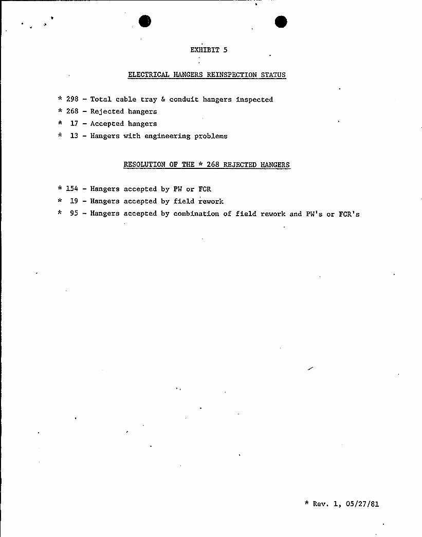
EXHIBIT 5
ELECTRICAL HANGERS REINSPECTION STATUS
* 298 —Total cable tray & conduit hangers inspected* 268 — Rejected hangers* 17 —Accepted hangers* 13 — Hangers with engineering problems
RESOLUTION OF THE * 268 REJECTED HANGERS
* 154 — Hangers accepted by PW or FCR
* 19 - Hangers accepted by field rework* 95 — Hangers accepted by combination of field rework and PW's or FCR's
* Rev. 1, 05/27/81

EXHIBIT NO. 6
REINSPECTION LIST OFHVAC DUCT SEISMIC SUPPORTS
RAB 190 ELEV.
F-1930
F-1931
F-1016
F-1000
F-1001
F«1008
F-1009
F-1005
F-1203
F-1011
F-1012R
F«1013
F-1014
F«1002
F-1004
F-1934
F-1200
F-1201
F«1933
RAB 236 ELEV.
F-1098
F-1291
F-1292
F-1101
F-1100
F-1099
F«1123
F«1086
F-1087
F-1088
F-1089
F-1090
F-1092
F-1093
F«1094
F-1095
F-1096
F-1097
F-1108
F-1109
F-1110
F-llll
F-1926
F-1927
F-1928
F-1929
F-1950
F-1951
F-1102
F-1952
F-1953
F-1954
F-1955
F-1956
EHDRAC Drawings 1364-12756 Rev. 5, 1364-16318 Rev. 1, 1364-16319 Rev- 1,1364-16320 Rev. 2 were used by QA to perform the reinspection on theabove hangers.

Exhibit 6
(continued) HVAC DUCT SElSMXC SUPPORTS
RAB 247 ELEV.
F-1696
F-1103
F-1104
F-1298
F-1105
F-1904
F-1301
F-1702
F-1489
F-1490
F-1501
F-1297
F-1483
F-1486
F-1300
F-1699
F-1303
F-1905
F-1901
F-1491
F-1906
F-1711
F-1703
F-1704
F-1305
F-1494
F-1707
F»1304
F«1307
F-1495
F-1708
F-1309
TOTAL HANGERS: 85

EXHIBIT 7 ~
REINSPECTION LIST OFCABLE TRAY & CONDUIT SUPPORT HANGER
1. 7021-EC2328
2 ~ 7041-ED2326
3 ~ 7021-HC2301
4. 7021-EC2327
5 7041-HD2315
6. 7021-EC2353-1
7. 7021-EC2352
8. 7021-EC2353-2
9 ~ 7041-ED2324 — Sect. R
10 '041-ED2324
11. 7041-HD2312
12. 7041-ED2325
13 '041-CD2310
14 '041-CD2308
15. 7041-ED2323
16. 7041-ED2328
17. 7041-ED2328 — Sects
18. 7041-ED2320 — Sect. H
19 '041-ED2320
20. 7041-ED2302
21 '041-ED2301-2
22. 7041-ED2301-1
23 '042-ED2358-3
24 '042-CD2364
25. 7042-ED2351-1
26 '042-ED2351-2
27 '042-ED2351-3
28. 7041-CD2311
29 '041-ED2312
30. 7041-ED2313
31. 7041-ED2314
32. 7041-ED2315
33. 7041-ED2316
34. 7041-ED2319
35. 7041-ED2322
36. 7041-ED2333
37. 7041-ED2321
38 '041-ED2308-1
39. 7041-ED2307-1
40. 7041-ED2307-2
41. 7041-ED2308-2
42. 7041-CD2309
43. 7041-ED2310
44. 7042-HD2365
45 '041-ED2303-1
46 '041-ED2303-2
47. 7041-ED2304
48. 7041-ED2306 — Sect. E
49 '041-ED2306 — Sect. F
50. 7041-EC2339

EXHIBIT 7
51. 7021-EC2323
52. 7021-EC2317
53. 7021-EC2322
54. 7021-HC2307
55. 7021-HC2306
56. 7021-HC2303
57. 7021-HC2302
58 '021-EC2326-2
59. 7021-EC2341
60. 7021-EC2326-1
61. 7042-ED2356
62 '042-ED2357-1
63. 7042-ED2357-2
* 64. DELETE
65. 7042-ED2375
66 '042-CD2365
67. 7042-ED2373
68. 7042-ED2352
69 '042-ED2366
70. 7042-ED2379
71 '041-ED2305-1
72 '041-ED2305-2
73. 7041-ED2305-3
74. 7041-ED2306-1
75 '041-ED2306-2
76. 7041-ED2309
77 '041-ED2311
* 78. DELETE
79 '042-ED2365
80. 7042-CD2369
* 81. DELETE
82. 7021-EC2325
83. 7042-ED2380
* 84. DELETE
85. 7042-HD2370
86. 7042-CD2363
87. 7042-ED2358-1
88 '042-ED2358-2
89. DELETE
* 90. DELETE
* 91. DELETE
* 92. DELETE
* 93. DELETE
94 . 7042-ED2353
95. 7042-CD2366
* 96. DELETE
* 97. DELETE
* 98. DELETE
* 99. DELETE
* 100. DELETE
* Rev. 1, 05/27/81

EXHIBIT 7
* 101. DELETE
102. 697S01-9
103. 697S01-10
104 . 697S01-11
105. 697S01-12
106. 697S01-13
107. 697S01-14
108. 697S01-15
109. 697S01-16
110. 697S01-17
111. 697S01-18
112. 7021-EC2304-2
113. 7021-EC2337
114 . 7021-EC2346-3
115. 7021-EC2360-1
116. 7021-EC2360-2
117. 7021-EC2324-
118. 7021-EC2302-2
119. 7021-EC2359
120. 7021-EC2316
121. 7021-EC2306-1
122. 7021-EC2306-2
123. 7021-EC2346-1
124 '021-EC2348-1
125. 7021-EC2348-2
126. 7021-EC2346-2
127. 7021-EC2356
128. 7021-EC2355
129. 7021-EC2305
130. 7021-EC2338
131. 7021-EC2304-4
132. 7021-EC2302-1
133 '021-EC2345
134 '021-EC2304-1
135. 7021-EC2304-3
136. 7021-EC2358-2
137. 7021-EC2358-1
138. 7021-EC2357
139. 7021-EC2340
140 '97S01-30
141 '97S01-31
142. 697S01-32
143. 697S01-33
144 . 697S01-34
145 '97S01-35
146. 697S01-36
147 '97S01-37
148. 697S01-38
149. 697S01-39
150. 697S01-40
* Rev. 1, 05/27/81

EXHIBIT 7
151. 697SOl&1
152. 697S01-52
153. 697S01-53
154 . 697S01-67
155. 697S01-60
156. 697S01-42
157. 697S01-43
176. 7026-EC2659-265
177. 7026-EC2659-270
178. 7026-EC2659-275
179- 7026-EC2659-279
180. 7026-EC2649
181. 7026-EC2634
182. 7026-EC2664«6
158.
159 ~
697S01-44
697S01-45
160. 697S01-46
161 '97S01-47
162 '97S01-48
163. 697S01-49
164 . 697S01-50
165. 697S01-51
166. 7021-HC2309
167. 7021-HC2308
168. 7021-EC2354-3
169. 7021-EC2354-2
170. 7021-EC2354-1
171. 7026-EC2638 — Sect. AE
172. 7026-EC2638 Sect. G
173. 7026-EC2638 - Sect. K
174 - 7026-EC2638 - Sect. H
175. 7026-EC2641
183- 7026-EC2664-8
184 '026-EC2608-1
185 '026-EC2608-2
186 '026-EC2601-1
187. 7026-EC2602-3
188. 7026-EC2635
189. 7026-EC2603
190. 7026-EC2613
191. 7026-EC2605
192. 7026-EC2602-2
193 '026-EC2602-1
,* 194. DELETE
* 195. DELETE
* 196. DELETE
* 197. DELETE
* 198. DELETE
* 199. DELETE
* 200. DELETE
* Rev. 1, 05/27/81

EXHIBIT 7
* 201. DELETE
* 202. DELETE
* 203. DELETE
* 204. DELETE
* 205. DELETE
* 206. DELETE
207. 699S02-131
208. 699S02-130
209. 699S02-100
210. 699S02-99
211. 699S02-98
212. 699S02-96
213. 699S02-95
214 . 699S02-97
'215. 699S02-96 & 97 Brace
-216. 699S02-27
'217. 699S02-28
218. 699S02-29
219. 699S02-30
220. 699S02-31
221. 699S02-35
222. 699S02-36
223. 699S02-37
224. 699S02-38
225. 699S02-39
226. 699S02-40
227 '99802%1
228. 699S02%4
229. 699S02-69
230. 699S02-72
231. 699S02-73
232. 699S02-74
233. 699S02-139
234 '99S02-140
235. 699S02-141
236. 699S02-142
237. 699S02-145
238. 699S02-146
239. 699S02-147
240. 699S02-18
241 '99S02-19
242. 699S02-20
243 '99S02-22
244 . 699S02-23
245. 699S02-24
<: 246. 699S02-25 ("Temp. Support" )
247 '99S02-26
248. 699S02-21
249. 699S02-117
250. 699S02-116
* Rev. 1, 05/27/81

EXHIBIT 7
251. 699S02-115
252. 699S02-114
253. 699S02-113
254. 699S02-112
255 . 699S02-ill & 112
256. 699S02-111
257. 699S02-110
258. 699S02-109
259. 699S02-109 & 108I
260." 699S02-108
261. 699S02-107
262. 699S02-91
263. 699S02-62
264 . 699S02-88
265. 699S02-119
266. 699S02-118
267. 699S02-15
268. 699S02-16
269.'99S02-17
270. 699S02-45
271. 699S02-48
272. 699S02-55
273. 699S02-54
274 . 699S02-53
275. 699S02-52
276- 699S02-144
277. 699S02%3
278. 699S02-14
279. 699S02-1
280. 699S02-136
281- 699S02-137
282. 699S02-138
* 283. DELETE
* 284. DELETE
285. 699S02-143
286. 699S02-56
287. 699S02-50
288. 699S02-51
289. 699S02-49
290. 699S02-47
291. 699S02-46
292. 699S02-101 & 100
293. 699S02-101
294. 699S02-102
* 295. 699S02-103 ("Temp. Support" )
296 '99S02-104
297. 699S02-105
298. 699S02-106
* 299. DELETE
* 300. DELETE
* Rev. 1, 05/27/81

301. 7026-EC260A2-3
* 302. DELETE
* 303. DELETE
* 304. DELETE
* 305. DELETE
* 306. DELETE
* 307. DELETE
* 308. DELETE
* 309. DELETE
* 310. DELETE
* 311. DELETE
312. 699S02-32
313. 699S02-33
314. 699S02-34
315. 699S02-57
.316. 699S02-58
317. 699S02-75 & 61
318. 699S02-79
319. 699S02-81
320. 699S02-82
321. 699S02-83
322. 699S02-84 .
323. 699S02-85
324. 699S02-86
325. 699S02-87
EXHIBIT 7 0326. 699S02-63
327. 699S02-64
328. 699S02-65
329. 699S02-68
330. 699S02-89
331. 699S02-90
332. 699S02-92
333. 699S02-93
334. 699S02-94
* 335. DELETE
336. 697S01-7
337. 697801-8
338. 697S01-22
339. 697S01-26
340. 7042-ED2374
341. 7021-EC2399
* 342. DELETE
tc 343, DELETE
* Rev. 1, 05/27/81

EXHIBIT NO. 8
REINSPECTION FCR & PW RESOLUTIONSREQUIRED FOR HVAC, CABLE TRAY
AND CONDUIT SUPPORT HANGERS
ELECTRICAL
PW-AS-152
* PW-AS-218
Rev. 2
Rev. 2
Rev. 1
Rev. 1
FCR-AS-334
PW-AS-346
PW-AS-347
PW-AS-349
HVAC
FCR-AS-334 Rev. 1
FCR-AS-349 Rev. 1
FCR-AS-372 Rev. 1
FCR-AS-372 Rev. 1
FCR-AS-380
FCR-AS-392 Rev. 1* FCR-AS-350
PW-AS-354
PW-AS-356
FCR-AS-372
PW-AS-380
PW-AS-391
Rev. 1
FCR-AS-446
FCR-AS-483
PW-.AS-508
PW-AS-509
PW-AS-510
PW-AS-511
PW-AS-392 Rev. 1
PW-AS-414
FCR-AS-394
FCR-AS-395
FCR-AS-396
FCR-AS-397
* PM-AS-398
PW-AS-399
PW-AS-400
PW-AS-401
PW-AS-402
PW-AS-403
PW-AS-404
FCR-AS-405
FCR-AS-414
FCR-AS-436
PW-AS-440
PM-AS-441
PM-AS-442
PW-AS-443
~ Rev. 1, 05/27/81
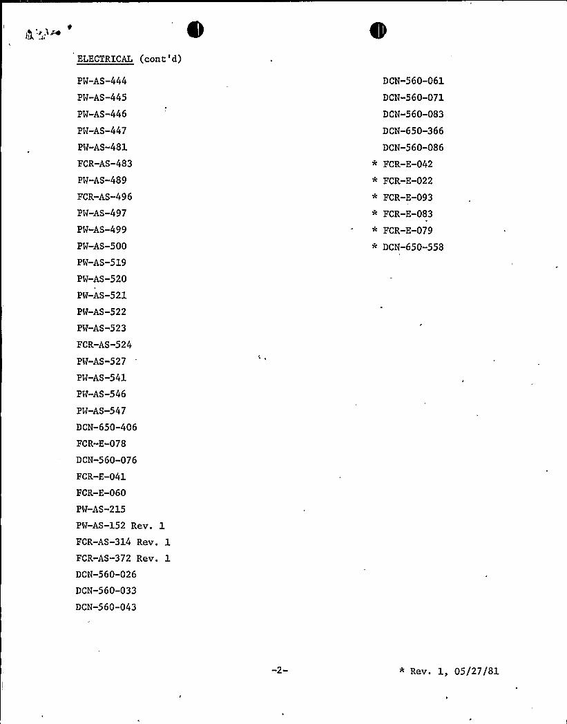
ELECTRICAL (cont'd)
Pw-AS-444
Pw-AS-445
PW-AS-446
Pw-AS-447
PW-AS-481
FCR-AS-483
Pw-AS-489
FCR-AS-496
Pw-AS-497
Pw-AS-499
PW-AS-500
PW-AS-519
PW-AS-520
PW-AS-521
PW-AS-522
PW-AS-523
FCR-AS-524
Pw-AS-527
PW-AS-541
PW-AS-546
PW-AS-547
DCN-650-406
FCR-E-078
DCN-560-076
FCR-E-041
FCR-E-060
PW-AS-215
PW-AS-152 Rev. 1
DCN-560-061
DCN-560-071
DCN-560-083
DCN-650-366
DCN-560-086
* FCR-E-042
* FCR-E-022
* FCR-E-093
* FCR-E-083
* FCR-E-079
* DCN-650-558
FCR-AS-314
FCR-AS-372
Rev. 1
Rev. 1
DCN-560-026
DCN-560-033
DCN-560-043
* Rev. 1, 05/27/81

v"m<i- 's. /i
Related Documents