BARE CONDUCTOR

Welcome message from author
This document is posted to help you gain knowledge. Please leave a comment to let me know what you think about it! Share it to your friends and learn new things together.
Transcript

BARE CONDUCTOR

Bare Aluminium Conductor 1
ACSR/AS (A1/SA1A) 3Concentric-Lay Stranded Aluminium Conductor/Aluminium Clad Steel Reinforced
ACSR (A1/S1A) 4Aluminium Conductor Steel Reinforced
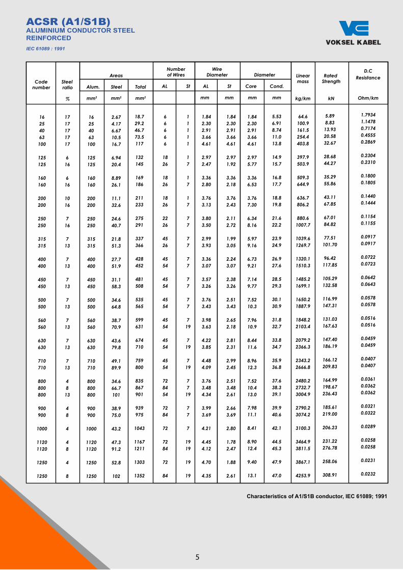
ACSR (A1/S1B) 5Aluminium Conductor Steel Reinforced
AS (SA1A) 6Concentric-Lay Stranded Aluminium-Clad Steel Conductor
THAL 8Thermal Aluminium Conductor
AAC 9All Aluminium Conductor
AAAC 11All Aluminium Alloy Conductor
GSW 13Galvanized Steel Wire Strands
ACFR/ ATW 15Aluminium Conductor Fiber Reinforced/Aluminium Trapezoid Wire
OPGW 18Optical Ground Wire
Bare Copper Conductor 24
BCC-H 26Bare Copper Conductor - Hard
BCC-1/2H 27Bare Copper Conductor – 1/2 Hard
BCC-H 28Hard Drawn Copper Stranded Conductors

Type- AAC (All Aluminium Conductor)
- HAL (Hard-Drawn Aluminium Stranded Conductor)
- AAAC (All Aluminium Alloy Conductor)
- THAL (Thermal Aluminium)
- ACSR (Aluminium Conductor Steel Reinforced)
- TACSR/ AS (Aluminium - Clad Steel Core thermal Resistant Aluminium Alloy)
- ACFR/ ATW (Aluminium Conductor Fiber
Reinforced/ Aluminium Trapezoid Wire)
- OPGW (Optical Ground Wire)
BARE ALUMINIUMCONDUCTOR
Type- AAC (All Aluminium Conductor)
- HAL (Hard-Drawn Aluminium Stranded Conductor)
- AAAC (All Aluminium Alloy Conductor)
- THAL (Thermal Aluminium)
- ACSR (Aluminium Conductor Steel Reinforced)
- TACSR/ AS (Aluminium - Clad Steel Core thermal Resistant Aluminium Alloy)
- ACFR/ ATW (Aluminium Conductor Fiber
Reinforced/ Aluminium Trapezoid Wire)
- OPGW (Optical Ground Wire)
1

Type- AAC (All Aluminium Conductor)
- HAL (Hard-Drawn Aluminium Stranded Conductor)
- AAAC (All Aluminium Alloy Conductor)
- THAL (Thermal Aluminium)
- ACSR (Aluminium Conductor Steel Reinforced)
- TACSR/ AS (Aluminium - Clad Steel Core thermal Resistant Aluminium Alloy)
- ACFR/ ATW (Aluminium Conductor Fiber
Reinforced/ Aluminium Trapezoid Wire)
- OPGW (Optical Ground Wire)
FEATUREThe conductors are applied for overhead power transmission purposes, medium tension overhead systems and distribution networks.
CONSTRUCTION
ConductorSeven or more aluminium wires of the same diameter are twisted together in concentric layers. When conductor consists of more than one layer, successive layers are twisted in opposite directions which is defined as right-hand lay (Z) or left-hand lay (S).
All Aluminium Conductor (AAC)The conductor shall be constructed of hard drawn aluminium wires with 99.45% minimum purity of aluminium. The Maximum resistivity at 20°C is 0.028264 ohm.mm²/m.
All Aluminium Alloy Conductor (AAAC)The conductor shall be constructed of hard drawn aluminium alloy wires which consists of:minimum 97.28% Aluminium+ 0.5% Magnesium+ 0.5% SiliconThe maximum resistivity at 20°C is 0.0328 ohm.mm²/m.
Thermal Aluminium (THAL)The conductor shall be constructed of hard drawn aluminium wires with 97.28% minimum purity of aluminium. The maximum resistivity at 20°C is 0.028735 ohm.mm²/m.
Aluminium Conductor Steel Reinforced (ACSR)The conductor shall be constructed of all aluminium conductor (AAC) and one or stranded seven Galvanized Steel Wires as a core, together built up in concentric layers. The galvanized steel wires which is used as a core shall be heat treatment and Zinc coated uniformly by using the method of hot dipped or electrolyte zinc coated.
Aluminium-Clad Steel Core Thermal Resistant Aluminium Alloy (TACSR/AS)The conductor shall be constructed of Thermal Resistant Aluminium Alloy wires (TAL wires) and stranded seven Aluminium-clad Steel wires (AS wires) as a core, together built up in concentric layers. The tensile strength of TAL wire after heating 230°C for one hour shall be more 90% than the value before heating. And the conductivity is more of 60% IACS (International Annealed Copper Standard). The conductivity of AS wire is 20.30% - 23.0% IACS.
Aluminium Conductor Fiber Reinforced / Aluminium Trapezoid Wire (ACFR/ ATW)ACSR/ATW is the next generation conductor cable. A key component of the ACFR / ATW is the unique stranded carbon fiber reinforced plastic or carbon fiber composite cable (CFCC). Compared to ACSR, CFCC has about one-fifth the weight, one-tenth the thermal expansion coefficient, and a higher tensile strength. It contains only nonmagnetic materials and, therefore, does not suffer from magnetic losses. It is highly flexible so that it can be wound around a small drum and is highly resistant to corrosion, unlike iron and steel. Last, its expected creeping deformation level at high temperatures is similar to that of iron.
Optical Ground Wire (OPGW)Glass optical fibers are placed in a plastic tube. The tube is inserted into a stainless steel, aluminum, or aluminum-coated steel tube, with some slack length of fiber allowed to prevent strain on the glass fibers. The buffer tubes are filled with grease to protect the fiber unit from water and to protect the steel tube from corrosion, the interstices of the cable are filled with grease. The tube is stranded into the cable with aluminum, aluminum alloy or steel strands, similar to an ACSR cable.
Specification:
ACSR/AS(A1/SA1A) SPLN T3.001-1 : 2015,
IEC 61089 : 1991ACSR
(A1/S1B) SPLN T3.001-1 : 2015, IEC 61089 : 1991
AS (SA1A)IEC 61232 : 1993, IEC 61089 : 1991,
ASTM B 415, ASTM B 416THAL
JIEC 197, IEC 61089, & IEC 62004AAC
ASTM B 231 – 16 (CLASS A AND CLASS AA)
AAACASTM B 399 : 2004, SPLN 41-8:1981
GSWSPLN T3.001-3 : 2008, JIS G 3537:1994
ACFRASTM B 233, ASTM B 609,
STM B 857OPGW
IEC60794-4-1, IEEE-1138
Other Speci�cationare available upon request
2

ACSR/AS (A1/SA1A)CONCENTRIC-LAY STRANDEDALUMINIUM CONDUCTOR,ALUMINIUM CLAD STEELREINFORCED
Specification : SPLN T3.001-1 : 2015, IEC 61089 : 1991
Physical and Electrical Properties
Type
250-A1/SA1A-26/7
450-A1/SA1A-54/7
SteelRatio
%
16.3
13.0
Cross Section Area
SA1A
mm2
39.1
56.5
Total
mm2
279
492
A1
mm2
240
436
Numberof Wire
A1
-
26
54
SA1A
-
7
7
Diameter of Wire
A1
mm
3.43
3.21
SA1A
mm
2.67
3.21
Diameter
Nom
mm
8.00
9.62
Act
mm
21.7
28.9
LinearDensity
BreakingForce
kg/km
921.5
1578.2
kN
D.C Resistance
at 20oC
Approx. Weight ofGrease
kg/km
Grease
Characteristics of A1/SA1A conductor, SPLN T3.001-1 : 2015
3

16254063100
125125
160160
200200
250250
315315
400400
450450
500500
560560
630630
710710
800800800
900900
1000
11201120
1250
1250
64.6100.9161.5254.4403.8
397.9503.9
509.3644.9
636.7806.2
880.61007.7
1039.61269.7
1320.11510.3
1485.21699.1
1650.21887.9
1848.22103.4
2079.22366.3
2343.22666.8
2480.22732.73004.9
2790.23074.2
3100.3
3464.93811.5
4253.9
3867.1
6.089.1314.4021.6334.33
29.1745.69
36.1857.69
44.2270.13
68.7287.67
79.03106.83
98.36123.04
107.47138.42
119.41153.80
133.74172.59
150.45191.77
169.56216.12
167.41205.33243.52
188.33226.50
209.26
234.53283.17
316.04
261.75
16254063100
125125
160160
200200
250250
315315
400400
450450
500500
560560
630630
710710
800800800
900900
1000
11201120
1250
1250
2.674.176.6710.516.7
6.9420.4
8.8926.1
11.132.6
24.640.7
21.851.3
27.751.9
31.158.3
34.664.8
38.770.9
43.679.8
49.189.9
34.666.7101
38.975.0
43.2
47.391.2
102
52.8
18.729.246.773.5117
132145
169186
211233
275291
337366
428452
481508
535565
599631
674710
759800
835867901
939975
1043
11671211
1352
1303
66666
1826
1826
1826
2226
4526
4554
4554
4554
4554
4554
4554
728454
7284
72
7284
84
72
11111
17
17
17
77
77
77
77
77
719
719
719
7719
77
7
1919
19
19
1.842.302.913.664.61
2.972.47
3.362.80
3.763.13
3.803.50
2.993.93
3.363.07
3.573.26
3.763.43
3.983.63
4.223.85
4.484.09
3.763.484.34
3.993.69
4.21
4.454.12
4.35
4.70
1.842.302.913.664.61
2.971.92
3.362.18
3.762.43
2.112.72
1.993.05
2.243.07
2.383.26
2.513.43
2.652.18
2.812.31
2.992.45
2.513.482.61
2.663.69
2.80
1.782.47
2.61
1.88
1.842.302.913.664.61
2.975.77
3.366.53
3.767.30
6.348.16
5.979.16
6.739.21
7.149.77
7.5210.3
7.9610.9
8.4411.6
8.9612.3
7.5210.413.0
7.9811.1
8.41
8.9012.4
13.1
9.40
5.536.918.7411.013.8
14.915.7
16.817.7
18.819.8
21.622.2
23.924.9
26.927.6
28.529.3
30.130.9
31.832.7
33.834.7
35.936.8
37.638.339.1
39.940.6
42.1
44.545.3
47.9
47.0
1717171717
616
616
616
1016
716
713
713
713
713
713
713
4813
48
4
48
8
4
Codenumber
Linearmass
kg/km
Rated Strength
kN
D.CResistance
Ohm/km
1.79341.14780.71740.45550.2869
0.23040.2310
0.18000.1805
0.14400.1444
0.11540.1155
0.09170.0917
0.07220.0723
0.06420.0643
0.05780.0578
0.05160.0516
0.04590.0459
0.04070.0407
0.03610.03620.0362
0.03210.0322
0.0289
0.02580.0258
0.0232
0.0231
Steel ratio
%
Areas
Alum. Steel Total
mm2 mm2 mm2
Numberof Wires
AL St
WireDiameter
AL St
mm mm
Diameter
Core Cond.
mm mm
Characteristics of A1/S1A conductor, IEC 61089; 1991
ACSR (A1/S1A)ALUMINIUM CONDUCTOR STEELREINFORCEDIEC 61089 : 1991
4
16254063100
125125
160160
200200
250250
315315
400400
450450
500500
560560
630630
710710
800800800
900900
1000
11201120
1250
1250
64.6100.9161.5254.4403.8
397.9503.9
509.3644.9
636.7806.2
880.61007.7
1039.61269.7
1320.11510.3
1485.21699.1
1650.21887.9
1848.22103.4
2079.22366.3
2343.22666.8
2480.22732.73004.9
2790.23074.2
3100.3
3464.93811.5
3867.1
4253.9
5.898.8313.9320.5832.67
28.6844.27
35.2955.86
43.1167.85
67.0184.82
77.51101.70
96.42117.85
105.29132.58
116.99147.31
131.03167.63
147.40186.19
166.12209.83
164.99198.67236.43
185.61219.00
206.23
231.22276.78
258.06
308.91
16254063
100
125125
160160
200200
250250
315315
400400
450450
500500
560560
630630
710710
800800800
900900
1000
11201120
1250
1250
2.674.176.6710.516.7
6.9420.4
8.8926.1
11.132.6
24.640.7
21.851.3
27.751.9
31.158.3
34.664.8
38.770.9
43.679.8
49.189.9
34.666.7101
38.975.0
43.2
47.391.2
52.8
102
18.729.246.773.5117
132145
169186
211233
275291
337366
428452
481508
535565
599631
674710
759800
835867901
939975
1043
11671211
1303
1352
66666
1826
1826
1826
2226
4526
4554
4554
4554
4554
4554
4554
728454
7284
72
7284
72
84
11111
17
17
17
77
77
77
77
77
719
719
719
7719
77
7
1919
19
19
1.842.302.913.664.61
2.972.47
3.362.80
3.763.13
3.803.50
2.993.93
3.363.07
3.573.26
3.763.43
3.983.63
4.223.85
4.484.09
3.763.484.34
3.993.69
4.21
4.454.12
4.70
4.35
1.842.302.913.664.61
2.971.92
3.362.18
3.762.43
2.112.72
1.993.05
2.243.07
2.383.26
2.513.43
2.652.18
2.812.31
2.992.45
2.513.482.61
2.663.69
2.80
1.782.47
1.88
2.61
1.842.302.913.664.61
2.975.77
3.366.53
3.767.30
6.348.16
5.979.16
6.739.21
7.149.77
7.5210.3
7.9610.9
8.4411.6
8.9612.3
7.5210.413.0
7.9811.1
8.41
8.9012.4
9.40
13.1
5.536.918.7411.013.8
14.915.7
16.817.7
18.819.8
21.622.2
23.924.9
26.927.6
28.529.3
30.130.9
31.832.7
33.834.7
35.936.8
37.638.339.1
39.940.6
42.1
44.545.3
47.9
47.0
1717171717
616
616
1016
716
713
713
713
713
713
713
713
4813
48
4
48
4
8
Codenumber
Linearmass
kg/km
Rated Strength
kN
D.CResistance
Ohm/km
1.79341.14780.71740.45550.2869
0.23040.2310
0.18000.1805
0.14400.1444
0.11540.1155
0.09170.0917
0.07220.0723
0.06420.0643
0.05780.0578
0.05160.0516
0.04590.0459
0.04070.0407
0.03610.03620.0362
0.03210.0322
0.0289
0.02580.0258
0.0231
0.0232
Steel ratio
%
Areas
Alum. Steel Total
mm2 mm2 mm2
Numberof Wires
AL St
WireDiameter
AL St
mm mm
Diameter
Core Cond.
mm mm
Characteristics of A1/S1B conductor, IEC 61089; 1991
ACSR (A1/S1B)ALUMINIUM CONDUCTOR STEELREINFORCEDIEC 61089 : 1991
5
Total Area
cmil
1,750,0001,500,0001,250,0001,000,000 900,000 800,000 750,000 700,000 650,000 600,000 550,000 500,000 450,000 400,000 350,000 300,000 250,000 211,600 167,800 133,000 105,600 66,360 41,740 26,240
AWG
. . . . . . . . . . . . . . . . . . . . . . . . . . . . . . . . . . . . . . . . . . . . . . . . . . . 0000 000 00 0 2 4 6
mm2
88675963150845640438135433030327925322820317815212610784.967.353.533.521.113.2
Number /Diameter of
Wire
mm
61/4.361/3.9861/3.6337/4.1837/3.9637/3.7337/3.6237/3.4937/3.3737/3.2337/3.1019/4.1219/3.9119/3.6919/3.4519/3.1919/2.917/4.427/3.937/3.57/3.127/2.477/1.967/1.55
ApproximateOverall
Diameter
mm2
38.7035.8232.6729.2627.7226.1125.3424.4323.5922.6121.7020.6019.5518.4517.2515.9514.5513.2611.7910.59.367.415.884.65
ApproximateWeight
kg/km
2431208217321393125011091045971.2905.5831.9766.2695626
557.5487.3416.7346.7294.7233
184.8146.8
9257.936.2
BreakingLoad
kN
25121517914613111610910194.991
83.974.266.859.552.046.638.832.525.720.417.010.66.694.18
DCResistance
20o C
Ohm/km
0.037810.044140.053060.065970.073510.082850.087960.094640.101500.110490.119950.132240.146830.164860.188600.220590.265090.311880.394500.497380.625920.998701.586002.53610
CurrentRating
A
13281223110497291084681678174670867263159154950345540536331326923217212895
All Aluminium Alloy Conductor
AAACALL ALUMINIUM ALLOY CONDUCTOR
Specification : ASTM B 399:2004
C
M
Y
CM
MY
CY
CMY
K
8 AAAC.pdf 1 30/12/2019 16:07:07
Total Area
cmil
1,750,0001,500,0001,250,0001,000,000 900,000 800,000 750,000 700,000 650,000 600,000 550,000 500,000 450,000 400,000 350,000 300,000 250,000 211,600 167,800 133,000 105,600 66,360 41,740 26,240
AWG
. . . . . . . . . . . . . . . . . . . . . . . . . . . . . . . . . . . . . . . . . . . . . . . . . . . 0000 000 00 0 2 4 6
mm2
88675963150845640438135433030327925322820317815212610784.967.353.533.521.113.2
Number /Diameter of
Wire
mm
61/4.361/3.9861/3.6337/4.1837/3.9637/3.7337/3.6237/3.4937/3.3737/3.2337/3.1019/4.1219/3.9119/3.6919/3.4519/3.1919/2.917/4.427/3.937/3.5
7/3.127/2.477/1.967/1.55
ApproximateOverall
Diameter
mm2
38.7035.8232.6729.2627.7226.1125.3424.4323.5922.6121.7020.6019.5518.4517.2515.9514.5513.2611.7910.59.367.415.884.65
ApproximateWeight
kg/km
2431208217321393125011091045971.2905.5831.9766.2695626
557.5487.3416.7346.7294.7233
184.8146.8
9257.936.2
BreakingLoad
kN
25121517914613111610910194.991
83.974.266.859.552.046.638.832.525.720.417.010.66.694.18
DCResistance
20o C
Ohm/km
0.037810.044140.053060.065970.073510.082850.087960.094640.101500.110490.119950.132240.146830.164860.188600.220590.265090.311880.394500.497380.625920.998701.586002.53610
CurrentRating
A
13281223110497291084681678174670867263159154950345540536331326923217212895
All Aluminium Alloy Conductor
AAACALL ALUMINIUM ALLOY CONDUCTOR
Specification : ASTM B 399:2004
C
M
Y
CM
MY
CY
CMY
K
8 AAAC.pdf 1 30/12/2019 16:07:07

AS (SA1A)CONCENTRIC-LAYSTRANDED ALUMINIUM-CLADSTEEL CONDUCTOR
Specification : IEC 61232 :1993,IEC 61089 : 1991, ASTM B 415 & ASTM B 416
No. of Wire/ diameter n/mm AS
7/3.20 7/3.50 19/2.50
Approx. Diameter of Conductor mm
9.6 10.5 12.5
Approx. net Weight of Conductor kg/km 375 448 626
CalculatedBreaking
Force (min)
KN
67.96 78.45 121.39
StandardLength
per Reel
Meter
2000 2000
2000
D.C Resistanceat 20 oC (max)
ohm/ km
1.53 1.27
0.925
Physical and Electrical Properties
Aluminium Clad Steel
6
Total Area
cmil
1,750,0001,500,0001,250,0001,000,000 900,000 800,000 750,000 700,000 650,000 600,000 550,000 500,000 450,000 400,000 350,000 300,000 250,000 211,600 167,800 133,000 105,600 66,360 41,740 26,240
AWG
. . . . . . . . . . . . . . . . . . . . . . . . . . . . . . . . . . . . . . . . . . . . . . . . . . . 0000 000 00 0 2 4 6
mm2
88675963150845640438135433030327925322820317815212610784.967.353.533.521.113.2
Number /Diameter of
Wire
mm
61/4.361/3.9861/3.6337/4.1837/3.9637/3.7337/3.6237/3.4937/3.3737/3.2337/3.1019/4.1219/3.9119/3.6919/3.4519/3.1919/2.917/4.427/3.937/3.5
7/3.127/2.477/1.967/1.55
ApproximateOverall
Diameter
mm2
38.7035.8232.6729.2627.7226.1125.3424.4323.5922.6121.7020.6019.5518.4517.2515.9514.5513.2611.7910.59.367.415.884.65
ApproximateWeight
kg/km
2431208217321393125011091045971.2905.5831.9766.2695626
557.5487.3416.7346.7294.7233
184.8146.8
9257.936.2
BreakingLoad
kN
25121517914613111610910194.991
83.974.266.859.552.046.638.832.525.720.417.010.66.694.18
DCResistance
20o C
Ohm/km
0.037810.044140.053060.065970.073510.082850.087960.094640.101500.110490.119950.132240.146830.164860.188600.220590.265090.311880.394500.497380.625920.998701.586002.53610
CurrentRating
A
13281223110497291084681678174670867263159154950345540536331326923217212895
All Aluminium Alloy Conductor
AAACALL ALUMINIUM ALLOY CONDUCTOR
Specification : ASTM B 399:2004
C
M
Y
CM
MY
CY
CMY
K
8 AAAC.pdf 1 30/12/2019 16:07:07

AS (SA1A)CONCENTRIC-LAYSTRANDED ALUMINIUM-CLADSTEEL CONDUCTOR
Specification : SPLN T3.001-3:2008
Area
mm2
30 37.5 48 75 120
No. of Wires
77777
Diameter Steel Wire mm mm
2.34 7.05 2.61 7.84 2.95 8.06 3.69 11.08 4.67 14.02
Approx. net Weight of Conductor
kg/km 200.3 250.4 320.5 500.7 801.2
CalculatedBreaking Force (min)
KN
40.2 50.25 64.32 93.75 132.00
CodeNumber
10
12.5162540
D.C Resistanceat 20 oC (max)
ohm/km
2.8637 2.2910 1.7898 1.1455 0.7159
Physical and Electrical Properties
Aluminium Clad Steel
Aluminium
7
Total Area
cmil
1,750,0001,500,0001,250,0001,000,000 900,000 800,000 750,000 700,000 650,000 600,000 550,000 500,000 450,000 400,000 350,000 300,000 250,000 211,600 167,800 133,000 105,600 66,360 41,740 26,240
AWG
. . . . . . . . . . . . . . . . . . . . . . . . . . . . . . . . . . . . . . . . . . . . . . . . . . . 0000 000 00 0 2 4 6
mm2
88675963150845640438135433030327925322820317815212610784.967.353.533.521.113.2
Number /Diameter of
Wire
mm
61/4.361/3.9861/3.6337/4.1837/3.9637/3.7337/3.6237/3.4937/3.3737/3.2337/3.1019/4.1219/3.9119/3.6919/3.4519/3.1919/2.917/4.427/3.937/3.5
7/3.127/2.477/1.967/1.55
ApproximateOverall
Diameter
mm2
38.7035.8232.6729.2627.7226.1125.3424.4323.5922.6121.7020.6019.5518.4517.2515.9514.5513.2611.7910.59.367.415.884.65
ApproximateWeight
kg/km
2431208217321393125011091045971.2905.5831.9766.2695626
557.5487.3416.7346.7294.7233
184.8146.8
9257.936.2
BreakingLoad
kN
25121517914613111610910194.991
83.974.266.859.552.046.638.832.525.720.417.010.66.694.18
DCResistance
20o C
Ohm/km
0.037810.044140.053060.065970.073510.082850.087960.094640.101500.110490.119950.132240.146830.164860.188600.220590.265090.311880.394500.497380.625920.998701.586002.53610
CurrentRating
A
13281223110497291084681678174670867263159154950345540536331326923217212895
All Aluminium Alloy Conductor
AAACALL ALUMINIUM ALLOY CONDUCTOR
Specification : ASTM B 399:2004
C
M
Y
CM
MY
CY
CMY
K
8 AAAC.pdf 1 30/12/2019 16:07:07

THALTHERMAL ALUMINIUM CONDUCTOR
Specification : JEC 197, IEC 61089 & IEC 62004
Construction Data
Conductor Size
mm2 240 400 510 660 850980
1,030 1,260
Stranding
no/mm 19/4.0 37/3.7 37/4.2 61/3.7 61/4.2 91/3.7 91/3.8 91/4.2
Calculated Sectional area
mm2 238.8 397.8 512.6 655.9 845.1978.4
1,032.0 1,260.8
OveralDiameter
mm20.0 25.9 29.4 33.3 37.8 40.7 41.8 46.2
Weight(approx.)
kg/km654.5
1,097.0 1,413.0 1,812.0 2,334.0 2,716.0 2,864.0 3,499.0
UltimateStrength
kg3,490 5,890 7,460 9,720 12,300 14,500 15,320 18,350
Calculated D.CResistance at 20OC
ohm/km0.1220 0.0737 0.0571 0.0448 0.0347 0.0302 0.0286 0.0234
Rated Current(at 150oC)
A 897 1,258 1,491 1,753 2,073 2,272 2,353 2,672
Thermal AluminiumConductor
8

Conductor sizeCM or AWG
3,500,0003,000,0002,750,0002,500,0002,250,0002,000,0001,750,0001,590,0001,510,0001,431,0001,351,0001,272,0001,192,0001,113,0001,033,500
Construction Data
Code name
BluebonnetTrilliumBitterrootLupineSagebrushCowslipJessamineCoreopsisGladiolusCarnationColumbineNarcissusHawthornMarigoldBluebeli
Stranding
Nos./mm127/4.216127/3.90491/4.41591/4.20991/3.99391/3.76461/4.30361/4.10061/3.99861/3.89161/3.78061/3.66861/3.55161/3.43237/4.244
Conductor sizeCM or AWG
3,500,0003,000,0002,750,0002,500,0002,250,0002,000,0001,750,0001,590,0001,510,0001,431,0001,351,0001,272,0001,192,0001,113,0001,033,500
Sectional area
mm1,7731,5201,3931,2661,1391,013886.9805.2765.6725.3684.4644.4604.1564.3523.6
Overalldiameter
mm54.8150.7548.5746.3043.9241.4038.7336.9035.9835.0234.0233.0131.9630.8929.71
Weight
kg/km4,9834,2743,8793,5253,1732,8192,4462,2212,1112,0001,8871,7771,6651,5561,443
Ultimatestrength
kg26,70022,80020,90019,00017,10015,60013,50012,20011,60011,00010,6009,9009,5508,9508,050
DC Resistance at20oC
Ohm/ Km0.016530.019270.020830.022920.025470.028660.032390.035680.037520.039610.041970.044580.047570.050920.05489
All Aluminium Conductor
AACALL ALUMINIUM CONDUCTOR
Specification : ASTM B 231 - 16 (Class A and Class AA)
9
Code name Conductor sizeCM or AWG
Standing
Nos./mm
Sectional area
mm
Overalldiameter
mm
UltimateStrength
kg
Weight
kg/km
Class
AA / A- oo -- oo -- oo -- oo -- oo -- oo -- oo -- oo -o oo oo -o oo -- oo -- oo -o o- o- o- oo -- oo -- oo oo oo oo oo oo oo -o -
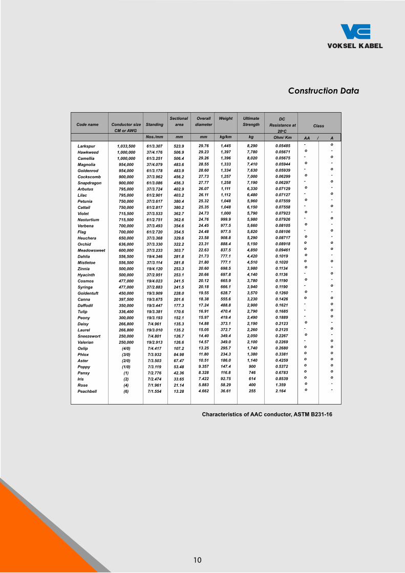
LarkspurHawkweedCamelliaMagnoliaGoldenrodCockscombSnapdragonArbutusLilacPetuniaCattailVioletNasturtiumVerbenaFlagHeucheraOrchidMeadowsweetDahliaMistletoeZinniaHyacinthCosmosSyringaGoldentuftCannaDaffodilTulipPeonyDaisyLaurelSneezewortValerianOxlipPhloxAsterPoppyPansyIrisRosePeachbell
1,033,5001,000,0001,000,000954,000954,000900,000900,000795,000795,000750,000750,000715,500715,500700,000700,000650,000636,000600,000556,500556,500500,000500,000477,000477,000450,000397,500350,000336,400300,000266,800266,800250,000250,000
(4/0)(3/0)(2/0)(1/0)(1)(2)(4)(6)
61/3.30737/4.17661/3.25137/4.07961/3.17837/3.96261/3.08637/3.72461/2.90137/3.61761/2.81737/3.53361/2.75137/3.49361/2.72037/3.36837/3.33037/3.23319/4.34637/3.11419/4.12037/2.95119/4.02337/2.88319/3.90919/3.67519/3.44719/3.38119/3.1937/4.96119/3.0107/4.80119/2.9137/4.4177/3.9327/3.5037/3.1197/2.7767/2.4747/1.9617/1.554
523.9506.9506.4483.6483.9456.2456.3402.9403.2380.4380.2362.7362.6354.6354.5329.6322.2303.7281.8281.8253.3253.1241.5241.5228.0201.6177.3170.6152.1135.3135.2126.7126.6107.284.9867.4753.4842.3633.6521.1413.28
29.7629.2329.2628.5528.6027.7327.7726.0726.1125.3225.3524.7324.7624.4524.4823.5823.3122.6321.7321.8020.6020.6620.1220.1819.5518.3817.2416.9115.9714.8815.0514.4014.5713.2511.8010.519.3578.3287.4225.8834.662
1,4451,3971,3961,3331,3341,2571,2581,1111,1121,0481,0481,000999.9977.5977.5908.8888.4837.5777.1777.1698.5697.8665.9666.1628.7555.6488.8470.4419.4373.1372.7349.4349.0295.7234.3186.0147.4116.892.7558.2936.61
8,2907,7808,0207,4107,6307,0007,1906,3306,4805,9606,1505,7905,9805,6605,8205,2905,1504,8504,4204,5103,9804,1403,7803,9403,5703,2302,9002,7902,4902,1902,2602,0502,1001,7401,3801,140900746614400255
0.054850.056710.056750.059440.059390.062990.062970.071290.071270.075590.075580.079230.079260.081050.081060.087170.089180.094610.10190.10200.11340.11360.11900.11900.12600.14260.16210.16850.18890.21230.21250.22670.22690.26800.33810.42590.53720.67830.85391.3592.164
DC Resistance at
20oC Ohm/ Km
Construction Data
Characteristics of AAC conductor, ASTM B231-16
10

All Aluminium Alloy Conductor
1,439,2001,348,8001,259,6001,165,1001,077,400927,200740,800652,400
559,500465,400394,500312,800
246,900195,700155,400123,300
77,47048,69030,580
ConductorSize
Code WordsA
Approx. Aluminium1350 Size Having
EquivalentRelevance
Size and Strandingof ACSR with
Equal Diameter
Required ConstructionMass
RatedStrength Nominal DC
Resistance at 20 o C
cmil cmilB AWGmm²
Size
mm² cmilB AWG mm²Stran-ding
No. ofWires
Diameter. ofWires Class lb per
1000 ftkg per
km kips kN Ohm per1000 ft
Ohm perkmin. mm
1,272,0001,192,5001,113,0001,033,500954,000795,000636,000556,500
477,000397,500336,400266,800
211,600167,800133,100105,600
66,36041,74026,240
1,272,0001,192,5001,113,0001,033,500954,000795,000636,000556,500
477,000397,500336,400266,800
211,600167,800133,100105,600
66,36041,74026,240
. . .
. . .
. . .
. . .
. . .
. . .
. . .
. . .
. . .
. . .
. . .
. . .
0000000000
246
. . .
. . .
. . .
. . .
. . .
. . .
. . .
. . .
. . .
. . .
. . .
. . .
0000000000
246
644.5604.2564.0523.7483.4402.8322.3282.0
241.7201.4170.5135.2
107.285.067.453.5
33.621.113.3
644.5604.2564.0523.7483.4402.8322.3282.0
241.7201.4170.5135.2
107.285.067.453.5
33.621.113.3
54/754/754/754/754/726/726/726/7
26/726/726/726/7
6/16/16/16/1
6/16/16/1
6161616161373719
19191919
7777
777
0.15360.14870.14370.13820.13290.15830.14150.1853
0.17160.15650.14410.1283
0.18780.16720.14900.1327
0.10520.08340.0661
3.903.783.653.513.384.023.594.71
4.363.983.663.26
4.774.253.783.37
2.672.121.68
AAAAAAAAAAAAAAAA
AAAA
AA,AA
AAAA,AAA,AAA,A
AA,AAA
13421258117510861005864.6690.8608.3
521.7433.9367.9291.6
230.2182.5144.9114.9
72.2445.4028.52
1999187817511620150212891028908.3
778.3648.6548.5435.1
343.2272.5215.6171.3
107.567.8042.58
46.843.941.037.935.030.524.421.9
18.815.613.310.5
8.566.795.394.27
2.801.761.11
20719418116715613510797.0
83.163.258.646.5
37.830.023.818.9
12.47.834.92
0.014000.014940.016000.017300.018700.021730.027200.03089
0.036020.043300.051070.06449
0.081620.10300.12970.1635
0.26010.41390.6588
0.045970.048930.052480.056750.061200.071330.089440.1012
0.11810.14170.16760.2112
0.26780.33730.42640.5365
0.85471.3562.159
729685638590547470375331
284236200159
12599.378.662.4
39.224.715.5
__________
GreeleyFlintElgin
DarienCairo
CantonButte
AllianceAmherstAnaheim
Azusa
AmesAltonAkron
Characteristics of AAAC, ASTM B 399 : 2004
AAACALL ALUMINIUM ALLOY CONDUCTOR
Specification : ASTM B 399:2004
11
Total Area
cmil
1,750,0001,500,0001,250,0001,000,000 900,000 800,000 750,000 700,000 650,000 600,000 550,000 500,000 450,000 400,000 350,000 300,000 250,000 211,600 167,800 133,000 105,600 66,360 41,740 26,240
AWG
. . . . . . . . . . . . . . . . . . . . . . . . . . . . . . . . . . . . . . . . . . . . . . . . . . . 0000 000 00 0 2 4 6
mm2
88675963150845640438135433030327925322820317815212610784.967.353.533.521.113.2
Number /Diameter of
Wire
mm
61/4.361/3.9861/3.6337/4.1837/3.9637/3.7337/3.6237/3.4937/3.3737/3.2337/3.1019/4.1219/3.9119/3.6919/3.4519/3.1919/2.917/4.427/3.937/3.57/3.127/2.477/1.967/1.55
ApproximateOverall
Diameter
mm2
38.7035.8232.6729.2627.7226.1125.3424.4323.5922.6121.7020.6019.5518.4517.2515.9514.5513.2611.7910.59.367.415.884.65
ApproximateWeight
kg/km
2431208217321393125011091045971.2905.5831.9766.2695626
557.5487.3416.7346.7294.7233
184.8146.8
9257.936.2
BreakingLoad
kN
25121517914613111610910194.991
83.974.266.859.552.046.638.832.525.720.417.010.66.694.18
DCResistance
20o C
Ohm/km
0.037810.044140.053060.065970.073510.082850.087960.094640.101500.110490.119950.132240.146830.164860.188600.220590.265090.311880.394500.497380.625920.998701.586002.53610
CurrentRating
A
13281223110497291084681678174670867263159154950345540536331326923217212895
All Aluminium Alloy Conductor
AAACALL ALUMINIUM ALLOY CONDUCTOR
Specification : ASTM B 399:2004
C
M
Y
CM
MY
CY
CMY
K
8 AAAC.pdf 1 30/12/2019 16:07:07
Total Area
cmil
1,750,0001,500,0001,250,0001,000,000 900,000 800,000 750,000 700,000 650,000 600,000 550,000 500,000 450,000 400,000 350,000 300,000 250,000 211,600 167,800 133,000 105,600 66,360 41,740 26,240
AWG
. . . . . . . . . . . . . . . . . . . . . . . . . . . . . . . . . . . . . . . . . . . . . . . . . . . 0000 000 00 0 2 4 6
mm2
88675963150845640438135433030327925322820317815212610784.967.353.533.521.113.2
Number /Diameter of
Wire
mm
61/4.361/3.9861/3.6337/4.1837/3.9637/3.7337/3.6237/3.4937/3.3737/3.2337/3.1019/4.1219/3.9119/3.6919/3.4519/3.1919/2.917/4.427/3.937/3.5
7/3.127/2.477/1.967/1.55
ApproximateOverall
Diameter
mm2
38.7035.8232.6729.2627.7226.1125.3424.4323.5922.6121.7020.6019.5518.4517.2515.9514.5513.2611.7910.59.367.415.884.65
ApproximateWeight
kg/km
2431208217321393125011091045971.2905.5831.9766.2695626
557.5487.3416.7346.7294.7233
184.8146.8
9257.936.2
BreakingLoad
kN
25121517914613111610910194.991
83.974.266.859.552.046.638.832.525.720.417.010.66.694.18
DCResistance
20o C
Ohm/km
0.037810.044140.053060.065970.073510.082850.087960.094640.101500.110490.119950.132240.146830.164860.188600.220590.265090.311880.394500.497380.625920.998701.586002.53610
CurrentRating
A
13281223110497291084681678174670867263159154950345540536331326923217212895
All Aluminium Alloy Conductor
AAACALL ALUMINIUM ALLOY CONDUCTOR
Specification : ASTM B 399:2004
C
M
Y
CM
MY
CY
CMY
K
8 AAAC.pdf 1 30/12/2019 16:07:07

AAAC
Physical Properties
Cross Sectional Section
Nominal Size
mm2
1625355050557095100120150150185240240300400500630800
1,000
Actual Size
mm2
16.8427.8334.3649.4845.7058.0775.5593.2799.30112.85157.62147.12181.60238.76242.54299.44431.18506.04643.24754.92
1,005.07
Number&
Diameter Wire
n/mm
7/1.757/2.257/2.507/3.0019/1.757/3.2519/2.2519/2.507/4.2519/2.7519/3.2537/2.2537/2.5019/4.0061/2.2561/2.5061/3.0061/3.2591/3.0091/3.2591/3.75
Approx.Overall
Diameter
mm
5.256.757.509.008.759.7511.2512.5012.7513.7516.2515.7517.5020.0020.2522.5027.0029.2533.0035.7541.25
Approx. NetWeight
kg/km
457694
135186160208256272310434406501657670827
1,1911,3981,7822,0912,784
CalculatedBreaking
Force
kg
480790980
1,4101,3001,6552,1502,6602,8303,2204,4904,1905,1756,8056,9108,530
12,29014,42018,33021,51528,640
DC.Resistance
at 20o C
ohm/km
1.9551.1830.9580.6650.7240.5670.4380.3550.3320.2930.2100.2250.1830.1370.1390.1110.0770.0660.0520.0440.033
CurrentCarryingCapacity
A
105135170210210220255320325365425425490585585670810930
1,0851,2551,450
Electrical Properties
Characteristics of AAAC, SPLN 41- 8: 1981
All Aluminium Alloy Conductor
AAACALL ALUMINIUM ALLOY CONDUCTOR
Specification : SPLN 41-8:1981
12
Total Area
cmil
1,750,0001,500,0001,250,0001,000,000 900,000 800,000 750,000 700,000 650,000 600,000 550,000 500,000 450,000 400,000 350,000 300,000 250,000 211,600 167,800 133,000 105,600 66,360 41,740 26,240
AWG
. . . . . . . . . . . . . . . . . . . . . . . . . . . . . . . . . . . . . . . . . . . . . . . . . . . 0000 000 00 0 2 4 6
mm2
88675963150845640438135433030327925322820317815212610784.967.353.533.521.113.2
Number /Diameter of
Wire
mm
61/4.361/3.9861/3.6337/4.1837/3.9637/3.7337/3.6237/3.4937/3.3737/3.2337/3.1019/4.1219/3.9119/3.6919/3.4519/3.1919/2.917/4.427/3.937/3.5
7/3.127/2.477/1.967/1.55
ApproximateOverall
Diameter
mm2
38.7035.8232.6729.2627.7226.1125.3424.4323.5922.6121.7020.6019.5518.4517.2515.9514.5513.2611.7910.59.367.415.884.65
ApproximateWeight
kg/km
2431208217321393125011091045971.2905.5831.9766.2695626
557.5487.3416.7346.7294.7233
184.8146.8
9257.936.2
BreakingLoad
kN
25121517914613111610910194.991
83.974.266.859.552.046.638.832.525.720.417.010.66.694.18
DCResistance
20o C
Ohm/km
0.037810.044140.053060.065970.073510.082850.087960.094640.101500.110490.119950.132240.146830.164860.188600.220590.265090.311880.394500.497380.625920.998701.586002.53610
CurrentRating
A
13281223110497291084681678174670867263159154950345540536331326923217212895
All Aluminium Alloy Conductor
AAACALL ALUMINIUM ALLOY CONDUCTOR
Specification : ASTM B 399:2004
C
M
Y
CM
MY
CY
CMY
K
8 AAAC.pdf 1 30/12/2019 16:07:07

CodeNumber
46.310
12.516
Area
mm2
27.142.767.884.7
108.4
Approx. netWeight ofConductor
kg/km
213.3335.9533.2666.5853.1
BreakingStrength
kN
36.355.987.4
109.3139.9
DCResistance
ohm/km
7.14454.53622.85782.28621.7861
No. of Wire
77777
Diameter
Steelmm
22.22.793.513.934.44
Wiremm
6.668.36
10.5311.7813.32
CodeNumber
46.310
12.516
Area
mm2
27.142.767.884.7
108.4
Approx. netWeight ofConductor
kg/km
213.3335.9533.2666.5853.1
BreakingStrength
kN
39.360.293.5116.9199.7
DCResistance
ohm/km
7.14454.53622.85782.28621.7861
No. of Wire
77777
Diameter
Steelmm
22.22.793.513.934.44
Wiremm
6.668.36
10.5311.7813.32
The Conditions of Raw Materials based on DC Resistance 9% IACS
The Conditions of Raw Materials based on DC Resistance 9% IACS
Galvanized Steel Wire Strands
Construction Data Galvanized Steel Wire (S1A)
Construction Data Galvanized Steel Wire (S2A)
Characteristics of GSW, SPLN T3.001 - 3: 2008
GSWGALVANIZED STEEL WIRE STRANDS
Specification : SPLN T3.001-3:2008
13
Total Area
cmil
1,750,0001,500,0001,250,0001,000,000 900,000 800,000 750,000 700,000 650,000 600,000 550,000 500,000 450,000 400,000 350,000 300,000 250,000 211,600 167,800 133,000 105,600 66,360 41,740 26,240
AWG
. . . . . . . . . . . . . . . . . . . . . . . . . . . . . . . . . . . . . . . . . . . . . . . . . . . 0000 000 00 0 2 4 6
mm2
88675963150845640438135433030327925322820317815212610784.967.353.533.521.113.2
Number /Diameter of
Wire
mm
61/4.361/3.9861/3.6337/4.1837/3.9637/3.7337/3.6237/3.4937/3.3737/3.2337/3.1019/4.1219/3.9119/3.6919/3.4519/3.1919/2.917/4.427/3.937/3.5
7/3.127/2.477/1.967/1.55
ApproximateOverall
Diameter
mm2
38.7035.8232.6729.2627.7226.1125.3424.4323.5922.6121.7020.6019.5518.4517.2515.9514.5513.2611.7910.59.367.415.884.65
ApproximateWeight
kg/km
2431208217321393125011091045971.2905.5831.9766.2695626
557.5487.3416.7346.7294.7233
184.8146.8
9257.936.2
BreakingLoad
kN
25121517914613111610910194.991
83.974.266.859.552.046.638.832.525.720.417.010.66.694.18
DCResistance
20o C
Ohm/km
0.037810.044140.053060.065970.073510.082850.087960.094640.101500.110490.119950.132240.146830.164860.188600.220590.265090.311880.394500.497380.625920.998701.586002.53610
CurrentRating
A
13281223110497291084681678174670867263159154950345540536331326923217212895
All Aluminium Alloy Conductor
AAACALL ALUMINIUM ALLOY CONDUCTOR
Specification : ASTM B 399:2004
C
M
Y
CM
MY
CY
CMY
K
8 AAAC.pdf 1 30/12/2019 16:07:07

Characteristics of GSW, JIS G 3537 : 1994
Cross Section Area
NominalSize
mm²
68
1014162225355055708095
100120135
ActualSize
mm²
5.57.9
10.814.117.822.029.137.246.256.367.379.388.0
102.0111.0137.0
No. ofwire/
Diameter
No/mm
7/1.07/1.27/1.47/1.67/1.87/2.07/2.37/2.67/2.97/3.27/3.57/3.87/4.07/4.37/4.57/5.0
Approx.Overall
Diameter
mm
3.03.64.24.85.46.06.97.88.79.610.511.412.012.913.515.0
Tensileload ofStand
Ton
0.6310.9081.241.622.052.533.344.285.326.507.739.1410.1011.7012.8015.80
Approx.net
weight ofconductor
kg/km
43.562.785.31111411742302943664465336286968058811090
Standardlength
per reel
mm
2000200020002000200020002000200020002000200010001000100010001000
Galvanized Steel Wire Strands
Construction Data
GSWGALVANIZED STEEL WIRE STRANDS
Specification : JIS G 3537:1994
14

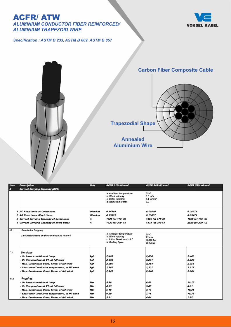
ACFR/ ATWALUMINIUM CONDUCTOR FIBER REINFORCED/ALUMINIUM TRAPEZOID WIRE
Specification : ASTM B 233, ASTM B 609, ASTM B 857
AnnealedAluminium Wire
Trapezodial Shape
Carbon Fiber Composite Cable
Physical and Electrical PropertiesSpecification of ACFR (Aluminium Conductor Fiber Reinforced)
Item Description Unit ACFR 315/ 40 mm² ACFR 365/ 40 mm² ACFR 550/ 40 mm²A Mechanical & Electrical Properties
1 Applicable Standard
ASTM B 233; ASTM B 609; ASTM B 857 and Factory Standard
ASTM B 233; ASTM B 609; ASTM B 857 and Factory Standard
ASTM B 233; ASTM B 609; ASTM B 857 and Factory Standard
2 Material
Core
Circular Stranded Composite Fibre Reinforced
Circular Stranded Composite Fibre Reinforced
Circular Stranded Composite Fibre Reinforced
ConductorFully Annealed Aluminium 1350-H0 "O" temper
Fully Annealed Aluminium 1350-H0 "O" temper
Fully Annealed Aluminium 1350-H0 "O" temper
3 ConstructionCore/ Mesengger Nos./ mm 7/ 2,60 7/ 2,76Conductor Nos./ mm 6/ 4,98; 10/ 4,98 8/ 4,82; 12/ 4,82 8/ 4,54; 12/ 4,54; 14/ 4,54
4 Shape of Aluminium - TRAPEZOID TRAPEZOID TRAPEZOID5 Calculated cross-section area
Core/ Mesengger mm² 37.17 41.9 56.3Conductor mm² 311.5 365.11 540.4Total mm² 348.47 406.99 596.7
6 Overall diameter, approximate mm 22.36 24.15 29.217 Approx. weight per 1.000 meters kg/km 919 1,080 1,5918 The diection of lay of the outermost layer9 Standard length per reel/ Drum Mtr 2,000 2,000 2,000
10 Minimum Rated Strength kg 9,575 11,614 15,2811 Modulus elasticity kgf/ mm² 11,719 11,719 11,71912 Coefficient of linear expansion 10 -6/ 20°C 0.60 0.60 0.6013 Max. DC resistant at 20°C Ohm/km 0.0892 0.0763 0.051614 Conductivity % IACS 63 63 6315 Allowable temperature
Continuous °C 175 175 175Emergency (short time) °C 200 200 200
16Temp. Coeficient of electrical resistance of conductor at 20°C /°C 0.00410 0.00410 0.00410
Specification of ACFR (Aluminium Conductor Fiber Reinforced)
Item Description Unit ACFR 315/ 40 mm² ACFR 365/ 40 mm² ACFR 550/ 40 mm²A Mechanical & Electrical Properties
1 Applicable Standard
ASTM B 233; ASTM B 609; ASTM B 857 and Factory Standard
ASTM B 233; ASTM B 609; ASTM B 857 and Factory Standard
ASTM B 233; ASTM B 609; ASTM B 857 and Factory Standard
2 Material
Core
Circular Stranded Composite Fibre Reinforced
Circular Stranded Composite Fibre Reinforced
Circular Stranded Composite Fibre Reinforced
ConductorFully Annealed Aluminium 1350-H0 "O" temper
Fully Annealed Aluminium 1350-H0 "O" temper
Fully Annealed Aluminium 1350-H0 "O" temper
3 ConstructionCore/ Mesengger Nos./ mm 7/ 2,60 7/ 2,76Conductor Nos./ mm 6/ 4,98; 10/ 4,98 8/ 4,82; 12/ 4,82 8/ 4,54; 12/ 4,54; 14/ 4,54
4 Shape of Aluminium - TRAPEZOID TRAPEZOID TRAPEZOID5 Calculated cross-section area
Core/ Mesengger mm² 37.17 41.9 56.3Conductor mm² 311.5 365.11 540.4Total mm² 348.47 406.99 596.7
6 Overall diameter, approximate mm 22.36 24.15 29.217 Approx. weight per 1.000 meters kg/km 919 1,080 1,5918 The diection of lay of the outermost layer9 Standard length per reel/ Drum Mtr 2,000 2,000 2,000
10 Minimum Rated Strength kg 9,575 11,614 15,2811 Modulus elasticity kgf/ mm² 11,719 11,719 11,71912 Coefficient of linear expansion 10 -6/ 20°C 0.60 0.60 0.6013 Max. DC resistant at 20°C Ohm/km 0.0892 0.0763 0.051614 Conductivity % IACS 63 63 6315 Allowable temperature
Continuous °C 175 175 175Emergency (short time) °C 200 200 200
16Temp. Coeficient of electrical resistance of conductor at 20°C /°C 0.00410 0.00410 0.00410
15
ACFR/ ATWALUMINIUM CONDUCTOR FIBER REINFORCED/ALUMINIUM TRAPEZOID WIRE
Specification : ASTM B 233, ASTM B 609, ASTM B 857
AnnealedAluminium Wire
Trapezodial Shape
Carbon Fiber Composite Cable
Specification of ACFR (Aluminium Conductor Fiber Reinforced)
Item Description Unit ACFR 315/ 40 mm² ACFR 365/ 40 mm² ACFR 550/ 40 mm²B Current Carrying Capacity (CCC)
Calculated based on the condition as follow : a. Ambient temperature 35 °Cb. Wind velocity 0,6 m/sc. Solar radiation 0,1 W/cm²d. Radiation factor 0,9 -
1 AC Resistance at Continuous Ohm/km 0.14905 0.12846 0.089712 AC Resistance Short times Ohm/km 0.15801 0.13607 0.094713 Current Carrying Capacity at Continuous A 1325 (at 175 °C) 1469 (at 175°C) 1886 (at 175 °C)4 Current Carrying Capacity at Short times A 1420 (at 200 °C) 1575 (at 200°C) 2029 (at 200 °C)
C Conductor SaggingCalculated based on the condition as follow : a. Ambient temperature 35 °C
b. Wind velocity 25 m/sc. Initial Tension at 15 °C 2400 kgd. Rulling Span 350 Mtrs
C.1 Tensions - On basic condition of temp. kgf 2,400 2,400 2,400 - On Temperature at T1, at full wind kgf 3,038 3,031 2,932 - Max. Continuous Cond. Temp. at Nil wind kgf 2,295 2,314 2,354 - Short time Conductor temperature, at Nil wind kgf 2,280 2,301 2,317 - Max. Continuous Cond. Temp. at full wind kgf 2,942 2,948 2,884
C.2 Sagging - On basic condition of temp. Mtr 5.89 6.89 10.15 - On Temperature at T1, at full wind Mtr 4.63 5.45 8.31 - Max. Continuous Cond. Temp. at Nil wind Mtr 6.16 7.14 10.31 - Short time Conductor temperature, at Nil wind Mtr 6.20 7.18 10.35 - Max. Continuous Cond. Temp. at full wind Mtr 3.51 4.44 7.72
Conductor Sagging
Tensions
Sagging
C
C.1
C.2
Calculated based on the condition as follow :
a. Ambient temperatureb. Wind velocityc. Solar radiationd. Radiation factor
35oC0,6 m/s0,1 W/cm²0,9 -
a. Ambient temperatureb. Wind velocityc. Initial Tension at 15oCd. Rulling Span
35oC25 m/s
350 mtrs
16

ACFR/ ATWALUMINIUM CONDUCTOR FIBER REINFORCED/
ALUMINIUM TRAPEZOID WIRE
Specification : ASTM B 233, ASTM B 609, ASTM B 857
Notes *1: TW(X.XX) stands for Trapezoidal Shaped Wires for which the equivalent outside diameter is X.XX mm. *2: Current Carrying Capacity is solved using the Cigre Method.
Calculation Conditons: Ambient temperature: 35°C, Wind: 0.9 m/s, Wind direction: 45°, Solar radiation: 0.1 W/cm2, Absorptivity and Emmisivity of conductor surface: 0.5, Frequency: 50 Hz, Sea level: 0m
at 75°C
at 175°C
Conductor
Core
Conductor
Core
No./mm
kN
mm
mm
mm2
mm2
mm2
kg/km
Ω/km
A
A
GPa
GPa
×10-6/ °C
×10-6/ °C
Aluminum No./mm
7/2.6
95.15
21.79
7.80
309
37.2
346
917.3
0.0910
678
1250
74.7
130
18.9
1.0
7/3.2
135.47
21.79
9.60
285
56.3
342
884.6
0.0985
652
1202
79.0
135
16.8
1.0
7/3.2
147.44
28.14
9.60
522
56.3
578
1540.2
0.0539
932
1748
74.5
135
19.1
1.0
7/4.2
228.03
28.14
12.50
474
95.4
570
1461.0
0.0593
890
1668
77.2
123
17.1
1.0
8/TW(4.44)12/TW(4.43)
10/TW(3.88)14/TW(3.90)
10/TW(3.97)14/TW(3.98)18/TW(3.98)
10/TW(5.01)14/TW(5.02)
10/TW(4.75)14/TW(4.77)
Equivalent conventional ACSR
Type of design
Size
Stranding*1
Rated Tensile Strength
Diameter
Cross Sectional Area
Weight
DC Resistance at 20°C
Current Carrying Capacity *2
Modulus of Elasticity
Coefficient of Thermal Expansion
Conductor
Core
Conductor
Core
Total
Core
Hawk Drake Curlew
Low Loss
310/40
Low Sag
290/55
Low Loss
520/55
7/3.6
186.39
31.62
10.80
659
71.3
730
1938.4
0.0426
1074
2032
73.7
126
19.3
1.0
8/TW(4.82)12/TW(4.83)16/TW(4.83)
Low Loss
660/70
7/5.1
331.05
31.62
15.20
573
141
714
1811.0
0.0490
1006
1900
79.6
127
16.1
1.0
12/TW(3.90)16/TW(3.90)20/TW(3.90)
Low Sag
570/140
Bison
7/2.9
126.63
27.00
8.80
486
47.3
533
1425.1
0.0578
892
1668
73.6
131
19.5
1.0
8/TW(4.13)12/TW(4.14)16/TW(4.16)
Low Loss
490/45
7/4.2
225.66
27.00
12.50
427
95.4
523
1331.1
0.0658
838
1565
78.0
123
16.7
1.0
Low Sag
430/95
12/TW(4.46)16/TW(4.47)
Zebra
7/3.2
148.48
28.62
9.60
542
56.3
599
1597.1
0.0518
954
1791
74.3
135
19.2
1.0
8/TW(4.38)12/TW(4.38)16/TW(4.38)
Low Loss
540/55
7/5.1
324.22
28.62
15.20
439
141
580
1437.1
0.0641
861
1614
82.4
127
14.7
1.0
Low Sag
440/140
Low Sag
470/95
The following is standard ACFR Design Example. Final design should be agreed with the conductor's manufacturer.
Standard ACFR Design Example
Performance Example compared to ACSR
Design Concept Transmission Loss Transmission Capaicty Sag
Low Loss
High Capacity
Low Sag-Low Loss
Low Sag-High Capacity
27% Less
More
9% Less
More
Same
120% More
Same
103% More
Same
Same
12% Less
10% Less
Case Study Accessories (Dead End Clamp and Mid Span Joint)
Supply SchemeHighCapacity
LowSag
*This figure depends on design and operating conditions.
Basic Design is the same as those for the conventional ACSR conductor, except for using an aluminum buffer which grabs the CFCC core securely.
Tokyo Rope provides CFCC to local conductor producer which will make ACFR.
ALUMINUM CONDUCTOR FIBER REINFORCED
Reference
LocalConductorProducer
Advisor: ACFR Design
Accessoriesdevelopment
Advisor: Accessories Installation TrainingConductor Stringing Training
TransmissionOwner
Contractor
AccessoriesProducer
*These pictures are for example purposes. Actual design to be decided by the customer's requirements.
Dead End Clamp Mid Span Joint
Reduction of total construction cost includig land, foundation and tower.
LowLoss
ACSR
100A 90A 100A
27% Less
ACSR
ACSR
ACSR
Longer spanDeduction of tower structual cost
Lower tower’s height
100A
100A
200A
93A
Twice capacity usingexsiting tower
TOKYO ROPE
ACFR / ATW
ACFR / ATWACSR
ACSR
ACSR / ATW ACSR / ATW
ACSR ACFR/ ATW
CRCC has Lighter Weight and Smaller Thermal ExpansionTrapezoidal Aluminium Wire Can Provide
Larger Cross Sectional Area
Steel Core
Round Shape
ACFR/ATW: Performance Compare to ACSR
AnnealedAluminium Wire
Trapezoidal Shape
Carbon Fiber Composite Cable
17
Total Area
cmil
1,750,0001,500,0001,250,0001,000,000 900,000 800,000 750,000 700,000 650,000 600,000 550,000 500,000 450,000 400,000 350,000 300,000 250,000 211,600 167,800 133,000 105,600 66,360 41,740 26,240
AWG
. . . . . . . . . . . . . . . . . . . . . . . . . . . . . . . . . . . . . . . . . . . . . . . . . . . 0000 000 00 0 2 4 6
mm2
88675963150845640438135433030327925322820317815212610784.967.353.533.521.113.2
Number /Diameter of
Wire
mm
61/4.361/3.9861/3.6337/4.1837/3.9637/3.7337/3.6237/3.4937/3.3737/3.2337/3.1019/4.1219/3.9119/3.6919/3.4519/3.1919/2.917/4.427/3.937/3.57/3.127/2.477/1.967/1.55
ApproximateOverall
Diameter
mm2
38.7035.8232.6729.2627.7226.1125.3424.4323.5922.6121.7020.6019.5518.4517.2515.9514.5513.2611.7910.59.367.415.884.65
ApproximateWeight
kg/km
2431208217321393125011091045971.2905.5831.9766.2695626
557.5487.3416.7346.7294.7233
184.8146.8
9257.936.2
BreakingLoad
kN
25121517914613111610910194.991
83.974.266.859.552.046.638.832.525.720.417.010.66.694.18
DCResistance
20o C
Ohm/km
0.037810.044140.053060.065970.073510.082850.087960.094640.101500.110490.119950.132240.146830.164860.188600.220590.265090.311880.394500.497380.625920.998701.586002.53610
CurrentRating
A
13281223110497291084681678174670867263159154950345540536331326923217212895
All Aluminium Alloy Conductor
AAACALL ALUMINIUM ALLOY CONDUCTOR
Specification : ASTM B 399:2004
C
M
Y
CM
MY
CY
CMY
K
8 AAAC.pdf 1 30/12/2019 16:07:07
Total Area
cmil
1,750,0001,500,0001,250,0001,000,000 900,000 800,000 750,000 700,000 650,000 600,000 550,000 500,000 450,000 400,000 350,000 300,000 250,000 211,600 167,800 133,000 105,600 66,360 41,740 26,240
AWG
. . . . . . . . . . . . . . . . . . . . . . . . . . . . . . . . . . . . . . . . . . . . . . . . . . . 0000 000 00 0 2 4 6
mm2
88675963150845640438135433030327925322820317815212610784.967.353.533.521.113.2
Number /Diameter of
Wire
mm
61/4.361/3.9861/3.6337/4.1837/3.9637/3.7337/3.6237/3.4937/3.3737/3.2337/3.1019/4.1219/3.9119/3.6919/3.4519/3.1919/2.917/4.427/3.937/3.5
7/3.127/2.477/1.967/1.55
ApproximateOverall
Diameter
mm2
38.7035.8232.6729.2627.7226.1125.3424.4323.5922.6121.7020.6019.5518.4517.2515.9514.5513.2611.7910.59.367.415.884.65
ApproximateWeight
kg/km
2431208217321393125011091045971.2905.5831.9766.2695626
557.5487.3416.7346.7294.7233
184.8146.8
9257.936.2
BreakingLoad
kN
25121517914613111610910194.991
83.974.266.859.552.046.638.832.525.720.417.010.66.694.18
DCResistance
20o C
Ohm/km
0.037810.044140.053060.065970.073510.082850.087960.094640.101500.110490.119950.132240.146830.164860.188600.220590.265090.311880.394500.497380.625920.998701.586002.53610
CurrentRating
A
13281223110497291084681678174670867263159154950345540536331326923217212895
All Aluminium Alloy Conductor
AAACALL ALUMINIUM ALLOY CONDUCTOR
Specification : ASTM B 399:2004
C
M
Y
CM
MY
CY
CMY
K
8 AAAC.pdf 1 30/12/2019 16:07:07

OPGWOPTICAL GROUND WIRE
Specification : IIEC60794-4-1, IEEE-1138
Structure
Technical Data
Temperature Range
Material No Material No. Material Dia.Fiber G.652 18 G.655 6
OPGW AL tube 1 Inner-Dia. 5.40 Outer-Dia. 7.60 mmStructure Layer1 20.3%AS wire 9 Diameter 3.80 mm
according to IEC60794-4-1, IEEE-1138 standardsStranding direction of outer layer is right hand(Z-Stranding)Cable Diameter 15.20 mmCable Weight 763 kg/kmSupporting Cross Section 124.5 mm2
Section of AS Wire 102.07 mm2
Section of AL Tube 22.46 mm2
Ultimate Tensile Strength (UTS) 127.6 kNRated Tensile Strength (RTS) 121.2 kN
Thermal Elongation Coefficient 13.7 ×10⁻⁶/�Permissible Maximum Working Stress (40% RTS) 389.3 N/mm2
Everyday Stress(EDS) (16%~25% RTS) 155.7 ~243.3 N/mm2
DC Resistance 0.504 Ω/kmShort Time Current ( 1s ) 9.7 kAShort Time Current Capacity I2t(40� ~200� ) 94.6 kA2SMinimum Bending Radius:Installation: 304 mm
Operating: 228 mmTemperature Installation -10� ~ +50 �
Range: Transportation and Operation -40� ~ +80 �Remarks: All Sizes and Values are Nominal Values
The deviation of the diamater and weight is 1%*D and 2%*W.
GreasedAs WireOP UnitAA Wire
PT. Voksel Electric, Tbk
Cable Type: OPGW - (18 G652 + 6 G655)-102/22 [121;94] Central Tube
Technical Data Modulus of Elasticity (E-Modulus) 142.9 kN/mm2
OPGW Cable Specifications Spec no. : OPGW_9
Cross Section:
OPGW – S1/(24 G652)-63/28 [53.6;77.1]
MaterialG652
20.3% AS wire14% AS wire
SUS Tube
No.12142
MaterialG.655
AA WireFibers (all tube)
AA Wire
No.12
2412
Material Dia.
DiameterDiameterTube Dia.Diameter
2.602.502.502.50
FiberCenterLayer 1
Layer 2
Installation -10 C ~ +50 C Transportation and Operation -40 C ~ +80 C
Cable Diameter 12.60 mmCable Weight 380 kg/kmSupporting Cross Section 83.8 mm²Section of AS Wire 24.94 mm²Section of AL Tube 58.90 mm²Ultimate Tensile Strength (UTS) 55.7 kNRated Tensile Strength (RTS) 53.8 kNModulus of Elasticity (E-Modulus) 95.8 kN/mm²Linear Expansion Coefficient 17.4 x 10⁻⁶
Permissible Maximum Working Stress (40% RTS) 256.6 N/mm²Everyday Stress (EDS) (16%~25% RTS) 102.6~160.4 N/mm²Ultimate Exceptional Stress (70% RTS) 449.1 N/mm²DC Resistance 0.501ohm/km
14.54 kA Short Time Current Capacity l²t 52.9 kA²SMinimum Bending Rac Installation : 252 mm Operating : 189 mmRatio between Pull and Weight 14.5 km
18
Total Area
cmil
1,750,0001,500,0001,250,0001,000,000 900,000 800,000 750,000 700,000 650,000 600,000 550,000 500,000 450,000 400,000 350,000 300,000 250,000 211,600 167,800 133,000 105,600 66,360 41,740 26,240
AWG
. . . . . . . . . . . . . . . . . . . . . . . . . . . . . . . . . . . . . . . . . . . . . . . . . . . 0000 000 00 0 2 4 6
mm2
88675963150845640438135433030327925322820317815212610784.967.353.533.521.113.2
Number /Diameter of
Wire
mm
61/4.361/3.9861/3.6337/4.1837/3.9637/3.7337/3.6237/3.4937/3.3737/3.2337/3.1019/4.1219/3.9119/3.6919/3.4519/3.1919/2.917/4.427/3.937/3.5
7/3.127/2.477/1.967/1.55
ApproximateOverall
Diameter
mm2
38.7035.8232.6729.2627.7226.1125.3424.4323.5922.6121.7020.6019.5518.4517.2515.9514.5513.2611.7910.59.367.415.884.65
ApproximateWeight
kg/km
2431208217321393125011091045971.2905.5831.9766.2695626
557.5487.3416.7346.7294.7233
184.8146.8
9257.936.2
BreakingLoad
kN
25121517914613111610910194.991
83.974.266.859.552.046.638.832.525.720.417.010.66.694.18
DCResistance
20o C
Ohm/km
0.037810.044140.053060.065970.073510.082850.087960.094640.101500.110490.119950.132240.146830.164860.188600.220590.265090.311880.394500.497380.625920.998701.586002.53610
CurrentRating
A
13281223110497291084681678174670867263159154950345540536331326923217212895
All Aluminium Alloy Conductor
AAACALL ALUMINIUM ALLOY CONDUCTOR
Specification : ASTM B 399:2004
C
M
Y
CM
MY
CY
CMY
K
8 AAAC.pdf 1 30/12/2019 16:07:07

OPGWOPTICAL GROUND WIRE
Specification : IEC60794-4-1, IEEE-1138
Thermal barrierAL-covered layer
Material No Material No. Material Dia.Fiber G.652 18 G.655 6
OPGW AL tube 1 Inner-Dia. 5.40 Outer-Dia. 7.60 mmStructure Layer1 20.3%AS wire 9 Diameter 3.80 mm
according to IEC60794-4-1, IEEE-1138 standardsStranding direction of outer layer is right hand(Z-Stranding)Cable Diameter 15.20 mmCable Weight 763 kg/kmSupporting Cross Section 124.5 mm2
Section of AS Wire 102.07 mm2
Section of AL Tube 22.46 mm2
Ultimate Tensile Strength (UTS) 127.6 kNRated Tensile Strength (RTS) 121.2 kN
Thermal Elongation Coefficient 13.7 ×10⁻⁶/�Permissible Maximum Working Stress (40% RTS) 389.3 N/mm2
Everyday Stress(EDS) (16%~25% RTS) 155.7 ~243.3 N/mm2
DC Resistance 0.504 Ω/kmShort Time Current ( 1s ) 9.7 kAShort Time Current Capacity I2t(40� ~200� ) 94.6 kA2SMinimum Bending Radius:Installation: 304 mm
Operating: 228 mmTemperature Installation -10� ~ +50 �
Range: Transportation and Operation -40� ~ +80 �Remarks: All Sizes and Values are Nominal Values
The deviation of the diamater and weight is 1%*D and 2%*W.
PT. Voksel Electric, Tbk
Cable Type: OPGW - (18 G652 + 6 G655)-102/22 [121;94] Central Tube
Technical Data Modulus of Elasticity (E-Modulus) 142.9 kN/mm2
OPGW Cable Specifications Spec no. : OPGW_9
Cross Section: AS wire
Optical fibers and Gel
loose tube
FRP
OPGW – (18 G652 + 6 G655)-102/22 [121;94]Central Tube
MaterialG652
20.3% AS wire
No.1819
MaterialG.655
Inner-Dia
No.6
5.40
Material Dia.
Outter-DiaDiameter
7.603.80
FiberAL tubeLayer 1
Installation -10 C ~ +50 C Transportation and Operation -40 C ~ +80 C
Cable Diameter 15.20 mmCable Weight 763 kg/kmSupporting Cross Section 124.5 mm²Section of AS Wire 102.07 mm²Section of AL Tube 22.46 mm²
Ultimate Tensile Strength (UTS) 127.6 kNRated Tensile Strength (RTS) 121.2 kN
Thermal Elongation Coefficient 13.7 x 10⁻⁶
Permissible Maximum Working Stress (40% RTS) 389.3 N/mm²Everyday Stress (EDS) (16%~25% RTS) 155.7~243.3 N/mm²DC Resistance 0.504 ohm/kmShort Time Current (1s) 9.7 kA
94.6 kA²SMinimum Bending Rac Installation : 304 mm Operating : 228 mm
Temperature Range
Structure
Technical Data
Bare Copper Conductor
FeatureThe conductors are applied forgrounding system.
CONSTRUCTIONConductorSeven or more copper wires the same nominal diameterare twisted together in concentric layers.When conductor consists of more than one layer, alternatelayers are twisted in opposite directions which is definedas right-hand lay (Z) or left-hand lay (S).
Bare Copper Conductor - Hard (BCC-H)The conductor has mechanic characteristic minimum428N/mm . The maximum resistivity at 20 C is 0.01786ohm. mm /m.
2
2
o
Bare Copper Conductor - Half Hard (BCC-1/2H)The conductor has mechanic characteristic between minimum 340N/mm .Maximum 410 N/mm .The maximum resistivity at 20 C is 0.01784 ohm. mm /m.
Annealed Copper Wire (BCW Soft)The Conductor has maximum resistivity at 20 C is 0.017241 ohm. mm /m.
Type:- Bare Copper Conductor - Half Hard (BCC-1/2H)- Bare Copper Conductor - Hard (BCC-H)- Annealed Copper Wire (BCW-Soft)
Spesification:SPLN 41-4:1981SPLN 41-5:1981JIS C 3102(Other specification are available upon request)
2
2
2
o
o
2
1
19
Total Area
cmil
1,750,0001,500,0001,250,0001,000,000 900,000 800,000 750,000 700,000 650,000 600,000 550,000 500,000 450,000 400,000 350,000 300,000 250,000 211,600 167,800 133,000 105,600 66,360 41,740 26,240
AWG
. . . . . . . . . . . . . . . . . . . . . . . . . . . . . . . . . . . . . . . . . . . . . . . . . . . 0000 000 00 0 2 4 6
mm2
88675963150845640438135433030327925322820317815212610784.967.353.533.521.113.2
Number /Diameter of
Wire
mm
61/4.361/3.9861/3.6337/4.1837/3.9637/3.7337/3.6237/3.4937/3.3737/3.2337/3.1019/4.1219/3.9119/3.6919/3.4519/3.1919/2.917/4.427/3.937/3.5
7/3.127/2.477/1.967/1.55
ApproximateOverall
Diameter
mm2
38.7035.8232.6729.2627.7226.1125.3424.4323.5922.6121.7020.6019.5518.4517.2515.9514.5513.2611.7910.59.367.415.884.65
ApproximateWeight
kg/km
2431208217321393125011091045971.2905.5831.9766.2695626
557.5487.3416.7346.7294.7233
184.8146.8
9257.936.2
BreakingLoad
kN
25121517914613111610910194.991
83.974.266.859.552.046.638.832.525.720.417.010.66.694.18
DCResistance
20o C
Ohm/km
0.037810.044140.053060.065970.073510.082850.087960.094640.101500.110490.119950.132240.146830.164860.188600.220590.265090.311880.394500.497380.625920.998701.586002.53610
CurrentRating
A
13281223110497291084681678174670867263159154950345540536331326923217212895
All Aluminium Alloy Conductor
AAACALL ALUMINIUM ALLOY CONDUCTOR
Specification : ASTM B 399:2004
C
M
Y
CM
MY
CY
CMY
K
8 AAAC.pdf 1 30/12/2019 16:07:07

OPGWOPTICAL GROUND WIRE
Specification : IEC60794-4-1, IEEE-1138
Thermal barrierAL-covered layer
Material No Material No. Material Dia.Fiber G.652 18 G.655 6
OPGW AL tube 1 Inner-Dia. 5.40 Outer-Dia. 7.60 mmStructure Layer1 20.3%AS wire 9 Diameter 3.80 mm
according to IEC60794-4-1, IEEE-1138 standardsStranding direction of outer layer is right hand(Z-Stranding)Cable Diameter 15.20 mmCable Weight 763 kg/kmSupporting Cross Section 124.5 mm2
Section of AS Wire 102.07 mm2
Section of AL Tube 22.46 mm2
Ultimate Tensile Strength (UTS) 127.6 kNRated Tensile Strength (RTS) 121.2 kN
Thermal Elongation Coefficient 13.7 ×10⁻⁶/�Permissible Maximum Working Stress (40% RTS) 389.3 N/mm2
Everyday Stress(EDS) (16%~25% RTS) 155.7 ~243.3 N/mm2
DC Resistance 0.504 Ω/kmShort Time Current ( 1s ) 9.7 kAShort Time Current Capacity I2t(40� ~200� ) 94.6 kA2SMinimum Bending Radius:Installation: 304 mm
Operating: 228 mmTemperature Installation -10� ~ +50 �
Range: Transportation and Operation -40� ~ +80 �Remarks: All Sizes and Values are Nominal Values
The deviation of the diamater and weight is 1%*D and 2%*W.
PT. Voksel Electric, Tbk
Cable Type: OPGW - (18 G652 + 6 G655)-102/22 [121;94] Central Tube
Technical Data Modulus of Elasticity (E-Modulus) 142.9 kN/mm2
OPGW Cable Specifications Spec no. : OPGW_9
Cross Section: AS wire
Optical fibers and Gel
loose tube
FRP
OPGW – (24 G652)-70/21 [90.4;48.5]Central Tube
Structure
Technical Data
Temperature Range
MaterialG652
20.3% AS wire
No.1819
MaterialG.655
Inner-Dia
No.6
5.40
Material Dia.
Outter-DiaDiameter
7.603.80
FiberAL tubeLayer 1
Installation -10 C ~ +50 C Transportation and Operation -40 C ~ +80 C
Cable Diameter 13.20 mmCable Weight 550 kg/kmSupporting Cross Section 91.4 mm²Section of AS Wire 70.17 mm²Section of AL Tube 21.28 mm²
Rated Tensile Strength (RTS) 90.4 kNModulus of Elasticity (E-Modulus) 137.3 kN/mm²Thermal Elongation Coefficient 13.9 x 10⁻⁶
Permissible Maximum Working Stress (40% RTS) 395.3 N/mm²Everyday Stress (EDS) (16%~25% RTS) 158.1~247 N/mm²Ultimate Exceptional Stress (70% RTS) 691.7 N/mm²DC Resistance 0.637 ohm/kmShort Time Current (1s) 7.0 kA
48.5 kA²SMinimum Bending Rac Installation : 528 mm Operating : 396 mmRatio of RTS to Weight 16.8 km
Bare Copper Conductor
FeatureThe conductors are applied forgrounding system.
CONSTRUCTIONConductorSeven or more copper wires the same nominal diameterare twisted together in concentric layers.When conductor consists of more than one layer, alternatelayers are twisted in opposite directions which is definedas right-hand lay (Z) or left-hand lay (S).
Bare Copper Conductor - Hard (BCC-H)The conductor has mechanic characteristic minimum428N/mm . The maximum resistivity at 20 C is 0.01786ohm. mm /m.
2
2
o
Bare Copper Conductor - Half Hard (BCC-1/2H)The conductor has mechanic characteristic between minimum 340N/mm .Maximum 410 N/mm .The maximum resistivity at 20 C is 0.01784 ohm. mm /m.
Annealed Copper Wire (BCW Soft)The Conductor has maximum resistivity at 20 C is 0.017241 ohm. mm /m.
Type:- Bare Copper Conductor - Half Hard (BCC-1/2H)- Bare Copper Conductor - Hard (BCC-H)- Annealed Copper Wire (BCW-Soft)
Spesification:SPLN 41-4:1981SPLN 41-5:1981JIS C 3102(Other specification are available upon request)
2
2
2
o
o
2
1
20

OPGWOPTICAL GROUND WIRE
Specification : IIEC60794-4-1, IEEE-1138
OPGW – S1/(24 G652)-59/30 [63.5;57.9]
Structure
Technical Data
Temperature Range
Material No Material No. Material Dia.Fiber G.652 18 G.655 6
OPGW AL tube 1 Inner-Dia. 5.40 Outer-Dia. 7.60 mmStructure Layer1 20.3%AS wire 9 Diameter 3.80 mm
according to IEC60794-4-1, IEEE-1138 standardsStranding direction of outer layer is right hand(Z-Stranding)Cable Diameter 15.20 mmCable Weight 763 kg/kmSupporting Cross Section 124.5 mm2
Section of AS Wire 102.07 mm2
Section of AL Tube 22.46 mm2
Ultimate Tensile Strength (UTS) 127.6 kNRated Tensile Strength (RTS) 121.2 kN
Thermal Elongation Coefficient 13.7 ×10⁻⁶/�Permissible Maximum Working Stress (40% RTS) 389.3 N/mm2
Everyday Stress(EDS) (16%~25% RTS) 155.7 ~243.3 N/mm2
DC Resistance 0.504 Ω/kmShort Time Current ( 1s ) 9.7 kAShort Time Current Capacity I2t(40� ~200� ) 94.6 kA2SMinimum Bending Radius:Installation: 304 mm
Operating: 228 mmTemperature Installation -10� ~ +50 �
Range: Transportation and Operation -40� ~ +80 �Remarks: All Sizes and Values are Nominal Values
The deviation of the diamater and weight is 1%*D and 2%*W.
GreasedAs WireOP UnitAA Wire
PT. Voksel Electric, Tbk
Cable Type: OPGW - (18 G652 + 6 G655)-102/22 [121;94] Central Tube
Technical Data Modulus of Elasticity (E-Modulus) 142.9 kN/mm2
OPGW Cable Specifications Spec no. : OPGW_9
Cross Section:
MaterialG652
14% AS wireSUS Tube
20.3% AS Wire
No.241510
MaterialG.655
AA WireFibers (all tube)
AA Wire
No.0
01212
Material Dia.
DiameterDiameterTube Dia.Diameter
2.602.502.502.50
FiberAL tubeLayer 1Layer 2
Installation -10 C ~ +50 C Transportation and Operation -40 C ~ +80 C
Cable Diameter 12.60 mmCable Weight 395 kg/kmSupporting Cross Section 88.8 mm²Section of AS Wire 29.85 mm²Section of AL Tube 58.90 mm²Ultimate Tensile Strength (UTS) 63.5 kNRated Tensile Strength (RTS) 61.2 kNModulus of Elasticity (E-Modulus) 99.9 kN/mm²Linear Expansion Coefficient 16.8 x 10⁻⁶
Permissible Maximum Working Stress (40% RTS) 275.8 N/mm²Everyday Stress (EDS) (16%~25% RTS) 110.3~172.4 N/mm²Ultimate Exceptional Stress (70% RTS) 482.7 N/mm²DC Resistance 0.492 ohm/km
15.2 kA Short Time Current Capacity l²t 57.9 kA²SMinimum Bending Rac Installation : 252 mm Operating : 189 mmRatio between Pull and Weight 15.8 km
21

OPGWOPTICAL GROUND WIRE
Specification : IIEC60794-4-1, IEEE-1138
Structure
Technical Data
Temperature Range
Material No Material No. Material Dia.Fiber G.652 18 G.655 6
OPGW AL tube 1 Inner-Dia. 5.40 Outer-Dia. 7.60 mmStructure Layer1 20.3%AS wire 9 Diameter 3.80 mm
according to IEC60794-4-1, IEEE-1138 standardsStranding direction of outer layer is right hand(Z-Stranding)Cable Diameter 15.20 mmCable Weight 763 kg/kmSupporting Cross Section 124.5 mm2
Section of AS Wire 102.07 mm2
Section of AL Tube 22.46 mm2
Ultimate Tensile Strength (UTS) 127.6 kNRated Tensile Strength (RTS) 121.2 kN
Thermal Elongation Coefficient 13.7 ×10⁻⁶/�Permissible Maximum Working Stress (40% RTS) 389.3 N/mm2
Everyday Stress(EDS) (16%~25% RTS) 155.7 ~243.3 N/mm2
DC Resistance 0.504 Ω/kmShort Time Current ( 1s ) 9.7 kAShort Time Current Capacity I2t(40� ~200� ) 94.6 kA2SMinimum Bending Radius:Installation: 304 mm
Operating: 228 mmTemperature Installation -10� ~ +50 �
Range: Transportation and Operation -40� ~ +80 �Remarks: All Sizes and Values are Nominal Values
The deviation of the diamater and weight is 1%*D and 2%*W.
GreasedAs WireOP UnitAA Wire
PT. Voksel Electric, Tbk
Cable Type: OPGW - (18 G652 + 6 G655)-102/22 [121;94] Central Tube
Technical Data Modulus of Elasticity (E-Modulus) 142.9 kN/mm2
OPGW Cable Specifications Spec no. : OPGW_9
Cross Section:
OPGW – S1/(24 G652)-63/28 [53.6;77.1]
MaterialG652
20.3% AS wire20.3% AS wire
SUS Tube20.3% AS Wire
No.121510
MaterialG.655
AA WireFibers (all tube)
AA Wire
No.0
01212
Material Dia.
DiameterDiameterTube Dia.Diameter
2.502.402.402.70
FiberCenterLayer 1
Layer 2
Installation -10 C ~ +50 C Transportation and Operation -40 C ~ +80 C
Cable Diameter 12.70 mmCable Weight 377 kg/kmSupporting Cross Section 90.5 mm²Section of AS Wire 27.53 mm²Section of AL Tube 62.98 mm² Rated Tensile Strength (RTS) 53.6 kNModulus of Elasticity (E-Modulus) 94.5 kN/mm²Linear Expansion Coefficient 17.8 x 10⁻⁶
Permissible Maximum Working Stress (40% RTS) 237.0 N/mm²Everyday Stress (EDS) (16%~25% RTS) 94.8~148.1 N/mm²Ultimate Exceptional Stress (70% RTS) 414.7 N/mm²DC Resistance 0.451 ohm/km
12.42 kA Short Time Current Capacity l²t 77.1 kA²SMinimum Bending Rac Installation : 254 mm Operating : 190 mmRatio between Pull and Weight 14.5 km
22

OPGWOPTICAL GROUND WIRE
Specification : IIEC60794-4-1, IEEE-1138
Structure
Technical Data
Temperature Range
Material No Material No. Material Dia.Fiber G.652 18 G.655 6
OPGW AL tube 1 Inner-Dia. 5.40 Outer-Dia. 7.60 mmStructure Layer1 20.3%AS wire 9 Diameter 3.80 mm
according to IEC60794-4-1, IEEE-1138 standardsStranding direction of outer layer is right hand(Z-Stranding)Cable Diameter 15.20 mmCable Weight 763 kg/kmSupporting Cross Section 124.5 mm2
Section of AS Wire 102.07 mm2
Section of AL Tube 22.46 mm2
Ultimate Tensile Strength (UTS) 127.6 kNRated Tensile Strength (RTS) 121.2 kN
Thermal Elongation Coefficient 13.7 ×10⁻⁶/�Permissible Maximum Working Stress (40% RTS) 389.3 N/mm2
Everyday Stress(EDS) (16%~25% RTS) 155.7 ~243.3 N/mm2
DC Resistance 0.504 Ω/kmShort Time Current ( 1s ) 9.7 kAShort Time Current Capacity I2t(40� ~200� ) 94.6 kA2SMinimum Bending Radius:Installation: 304 mm
Operating: 228 mmTemperature Installation -10� ~ +50 �
Range: Transportation and Operation -40� ~ +80 �Remarks: All Sizes and Values are Nominal Values
The deviation of the diamater and weight is 1%*D and 2%*W.
GreasedAs WireOP UnitAA Wire
PT. Voksel Electric, Tbk
Cable Type: OPGW - (18 G652 + 6 G655)-102/22 [121;94] Central Tube
Technical Data Modulus of Elasticity (E-Modulus) 142.9 kN/mm2
OPGW Cable Specifications Spec no. : OPGW_9
Cross Section:
OPGW – S1/(24 G652)-77;38 [71.3;100.1]
MaterialG652
14% AS wireSUS Tube
No.24151
MaterialG.655
AA WireFibers (all tube)
AA Wire
No.0
02412
Material Dia.
DiameterDiameterTube Dia.Diameter
2.852.852.802.85
FiberCenterLayer 1
Layer 2
Installation -10 C ~ +50 C Transportation and Operation -40 C ~ +80 C
Cable Diameter 14.25 mmCable Weight 485 kg/kmSupporting Cross Section 114.8 mm²Section of AS Wire 38.28 mm²Section of AL Tube 76.55 mm²Ultimate Tensile Strength (UTS) 71.3 kNRated Tensile Strength (RTS) 97.3 kNModulus of Elasticity (E-Modulus) 99.9 kN/mm²Linear Expansion Coefficient 17.5 x 10⁻⁶
Permissible Maximum Working Stress (40% RTS) 248.8 N/mm²Everyday Stress (EDS) (16%~25% RTS) 99.4~155.3 N/mm²Ultimate Exceptional Stress (70% RTS) 434.7 N/mm²DC Resistance 0.363 ohm/km
10.00 kA Short Time Current Capacity l²t 100.1 kA²SMinimum Bending Rac Installation : 285 mm Operating : 213 mmRatio between Pull and Weight 15.0 km
23
BARECOPPERCONDUCTOR
Type :
- Bare Copper Conductor – Half Hard (BCC-1/2H) - Bare Copper Conductor – Hard (BCC-H)
24

Bare Copper Conductor
FeatureThe conductors are applied forgrounding system.
CONSTRUCTIONConductorSeven or more copper wires the same nominal diameterare twisted together in concentric layers.When conductor consists of more than one layer, alternatelayers are twisted in opposite directions which is definedas right-hand lay (Z) or left-hand lay (S).
Bare Copper Conductor - Hard (BCC-H)The conductor has mechanic characteristic minimum428N/mm . The maximum resistivity at 20 C is 0.01786ohm. mm /m.
2
2
o
Bare Copper Conductor - Half Hard (BCC-1/2H)The conductor has mechanic characteristic between minimum 340N/mm .Maximum 410 N/mm .The maximum resistivity at 20 C is 0.01784 ohm. mm /m.
Annealed Copper Wire (BCW Soft)The Conductor has maximum resistivity at 20 C is 0.017241 ohm. mm /m.
Type:- Bare Copper Conductor - Half Hard (BCC-1/2H)- Bare Copper Conductor - Hard (BCC-H)- Annealed Copper Wire (BCW-Soft)
Spesification:SPLN 41-4:1981SPLN 41-5:1981JIS C 3102(Other specification are available upon request)
2
2
2
o
o
2
1
Specification:
SPLN 41-4:1981 SPLN 41-5:1981
BS 7884 : 1997
Other specificationare available upon request
FEATUREThe conductors are applied for grounding system.
CONSTRUCTION
ConductorSeven or more copper wires the same nominaldiameter are twisted together in concentric layers.When conductor consists of more than one layer,alternate layers are twisted in opposite directionswhich is defined as right-hand lay (Z) or left-hand lay (S).
Bare Copper Conductor – Hard (BCC-H)The conductor mechanic characteristic minimum 428N/mm².The maximum resistivity at 20°C is 0.01786 ohm.mm²/m.
Bare Copper Conductor – Half Hard (BCC-1/2H)The conductor has mechanic characteristic betweenminimum 340N/mm². The maximum resistivityat 20°C is 0.01784 ohm.mm²/m.
25

Bare Copper Conductor
FeatureThe conductors are applied forgrounding system.
CONSTRUCTIONConductorSeven or more copper wires the same nominal diameterare twisted together in concentric layers.When conductor consists of more than one layer, alternatelayers are twisted in opposite directions which is definedas right-hand lay (Z) or left-hand lay (S).
Bare Copper Conductor - Hard (BCC-H)The conductor has mechanic characteristic minimum428N/mm . The maximum resistivity at 20 C is 0.01786ohm. mm /m.
2
2
o
Bare Copper Conductor - Half Hard (BCC-1/2H)The conductor has mechanic characteristic between minimum 340N/mm .Maximum 410 N/mm .The maximum resistivity at 20 C is 0.01784 ohm. mm /m.
Annealed Copper Wire (BCW Soft)The Conductor has maximum resistivity at 20 C is 0.017241 ohm. mm /m.
Type:- Bare Copper Conductor - Half Hard (BCC-1/2H)- Bare Copper Conductor - Hard (BCC-H)- Annealed Copper Wire (BCW-Soft)
Spesification:SPLN 41-4:1981SPLN 41-5:1981JIS C 3102(Other specification are available upon request)
2
2
2
o
o
2
1
Cross Sectional Area
Nominal Size
mm²
61010162535507095
120150185240300400500
No. of Wire/
Diameter
n/mm
1/2.801/3.507/1.357/1.707/2.107/2.50
19/1.8019/2.1019/2.5019/2.8037/2.2537/2.5061/2.2561/2.5061/2.8961/3.23
Approx.Overall
Diameter
mm
2.83.5
4.055.16.37.59.0
10.512.514.015.717.520.222.510
29.1
Approx.
Net Weightof Conductor
kg/km
558690
143218309437595844
1,0591,3341,6472,2042,7213,6364,542
ActualSize
mm²
6.169.62
10.0215.8924.2534.3648.3665.8293.27117.00147.10181.60242.50299.40400.10499.10
Cross Sectional Area
Nominal Size
mm²
61010162535507095120150185240300400500
ActualSize
mm²
6.169.6210.0215.8924.2534.3648.3665.8293.27117.00147.10181.60242.50299.40400.10499.10
Max. DCConductor Resistance
at 20o C
Ohm/km
BCC-H
2.89941.85651.81811.14650.75120.53020.37850.27810.19630.15650.12440.10080.07550.06110.04580.0367
Bare Copper
Dimensional andMechanical Data
Electrical Data
BCC-HBARE COPPER CONDUCTOR - HARD Specification : SPLN 41 - 5:1981 & SNI 04 - 3894:1995
26

Cross Sectional Area
Nominal Size
mm²
61010162535507095
120150185240300400500
No. of Wire/
Diameter
n/mm
1/2.801/3.507/1.357/1.707/2.107/2.50
19/1.8019/2.1019/2.5019/2.8037/2.2537/2.5061/2.2561/2.5061/2.8961/3.23
Approx.
Net Weightof Conductor
kg/km
558690
143218309437595844
1,0591,3341,6472,2042,7213,6364,542
ActualSize
mm²
6.169.62
10.0215.8924.2534.3648.3665.8293.27117.00147.10181.60242.50299.40400.10499.10
Cross Sectional Area
Nominal Size
mm²
61010162535507095120150185240300400500
ActualSize
mm²
6.169.6210.0215.8924.2534.3648.3665.8293.27117.00147.10181.60242.50299.40400.10499.10
Max. DCConductor Resistance
at 20o C
Ohm/km
BCC-1/2H
2.89611.85451.81601.14520.75040.52960.37810.27780.19610.15630.12430.10070.07540.06110.04570.0366
Bare Copper
Dimensional andMechanical Data
Electrical Data
BCC-1/2HBARE COPPER CONDUCTOR - 1/2 HARDSpecification :SPLN 41 - 4:1981 & SNI 04 - 3895:1995
27

Nominal Area of Cross-Section of
Stranded Conductor
mm²
10141616253232355050707095100120125150150185185
Construction(Stranding and Wire
Diameter)
number/mm
7/1.357/1.603/2.657/1.707/2.103/3.757/2.467/2.507/3.00
19/1.807/3.55
19/2.1019/2.507/4.30
19/2.8019/2.9019/3.2037/2.2519/3.5537/2.50
OverallDiameter of Conductor
(Approx.)
mm
4.054.805.705.106.308.067.387.509.009.00
10.6510.5012.5012.9014.0014.5016.0015.7517.7517.50
Nominal Mass per Unit Length
kg/km
89.82126.2148.3142.4217.3296.9298.2308.0443.5435.8621.1593.2840.7911.2105511311377133416951647
Minimum Breaking Load
N
37525267619459469073124001244212860185201770025930240903414036540428304594055940538806886066490
Nominal
Ohm/Km
89.82126.2148.3142.4217.3296.9298.2308.0443.5435.8621.1593.2840.7911.2105511311377133416951647
Max
Ohm/Km
1.8291.3031.1061.154
0.75630.55200.54970.53370.37060.38190.26460.28060.19800.18100.15780.14710.12080.1264
0.098150.1024
Resistance at 20oC
CONSTRUCTION DATA
BCC-HHARD DRAWN COPPERSTRANDED CONDUCTORSSpecification : BS 7884:1997
28

TOTAL CABLE SOLUTION PROVIDER
Executive OfficeMenara Karya 3rd Floor, Suite D, Jl. HR. Rasuna Said Blok X-5 Kav 1-2,Jakarta 2950 - IndonesiaP. (+62 21) 5794 4622
Jl. Raya Narogoong Km. 16, Cileungsi, Bogor 6820 - IndonesiaP. (+62 21) 8230 525, 8249 1720
Hotline Sales Service(+62 21) 8249 3329
WW
W.V
OK
SE
L.C
O.I
D
Related Documents