Review of the mechanical design of the final focusing region of the HIF Point Design T. Brown ARIES Project Meeting ARIES Project Meeting January 8, 2003

Review of the mechanical design of the final focusing region of the HIF Point Design T. Brown ARIES Project Meeting January 8, 2003.
Dec 22, 2015
Welcome message from author
This document is posted to help you gain knowledge. Please leave a comment to let me know what you think about it! Share it to your friends and learn new things together.
Transcript

Review of the mechanical design of the final focusing
region of the HIF Point Design
T. Brown
ARIES Project MeetingARIES Project Meeting
January 8, 2003

Overall Design Philosophy
• Quadrupole magnets are located in common cryostats. One cryostat structure houses magnet 1 quadrupoles and a second cryostat contains magnets 2 and 3 quadrupole assemblies.
• Intermagnet supporting structure is used to align and support magnets 1,2 and 3 plus add to the overall shielding requirements.
• The current design assumes that a complete focus magnet section is replaced if maintenance is required.

An isometric view illustrating the configuration arrangement of the Robust Point Design (RPD-2002)
for a Heavy Ion Power Plant

Accelerator and Final Focus Array Parameters
Parameter ValueAccelerator Number of beams 120 Ion species-A Bi-209 Ion energy - foot pulse 3.3 GeV No. of foot pulse beams 48 Ion energy - main pulse 4.0 GeV No. of main pulse beams 72Final Focus Array Maximum array angle 24° Beam half angle 10 mrad Chamber array size 9x9 Angle between array rows 5.4° Illumination 2-sided Dist. to end of first magnet 6 m
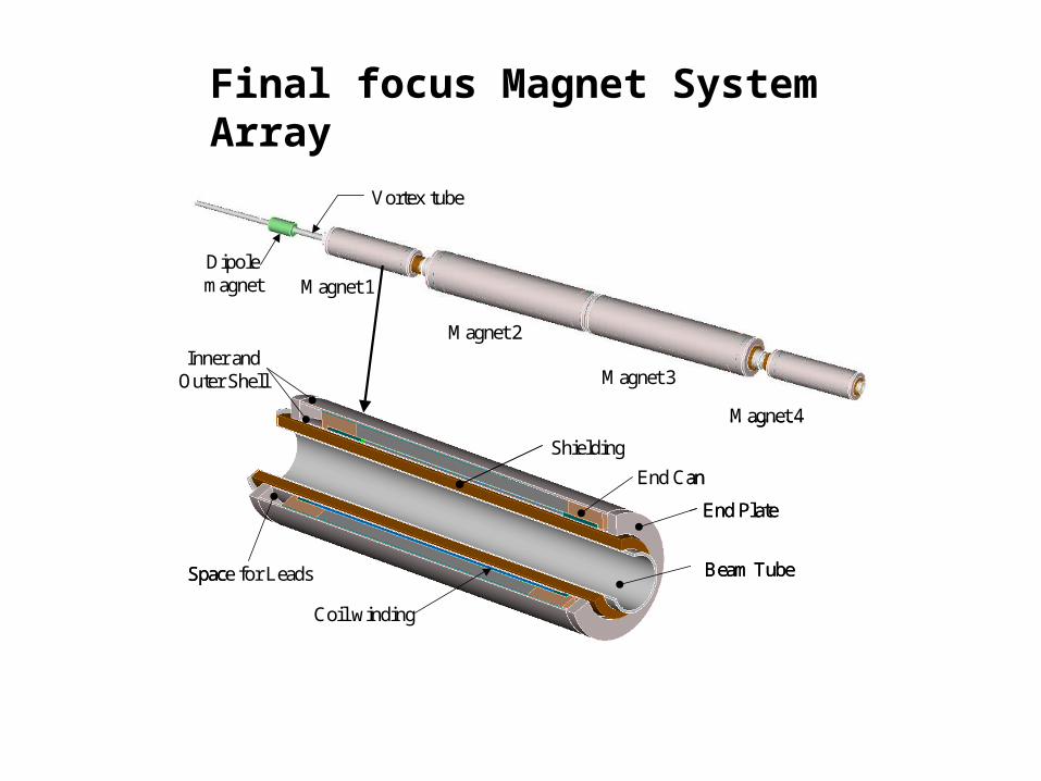
Final focus Magnet System Array
Magnet 1
Magnet 2
Vortex tube
Dipole magnet
Collar
Space for Leads
End Plate
End Can
Coil winding
Shielding
Beam Tube
Inner and Outer Shell
Magnet 4
Magnet 3
Magnet 1
Magnet 2
Vortex tube
Dipole magnet
Collar
Space for Leads
End Plate
End Can
Coil winding
Shielding
Beam Tube
Inner and Outer Shell
Magnet 4
Magnet 3

R dRComponent Details (cm) (cm)Bore inner radius 12 Pipe and water 0.5Shielding inner radius 12.5 Shield thickness 5 Gap 0.5Cold mass 18 Microcrystalline 0.5 LHe inner vessel 0.5Winding inner radius 19 Winding build 1.5Winding outer radius 20.5 Ground wrap 0.2 Coil support shell 6 Slip plane 0.1 Outer shell thickness 1Coil support structure 27.8
Magnet 1 Build Dimensions
Space for Leads
End Plate End Can
Coil winding
Shielding
Beam Tube
Inner and
Outer Shell

quad1 B'(T/m) B(rp)(T) rp(cm) l(m) ldrift2(m)1st 21.8 2.61 12 1.33 6.332nd -19.1 -3.6 18.9 3 1.13rd 19.1 3.74 19.6 3 0.54th -21.8 -2.99 13.7 1.33 1.1
Final Focus Quadrupole Parameters
Conductor, Cable and Coil Parameters
Parameter Symbol Units Magnet 1 Magnet 2Operating Gop T/m 21.8 19.1Coil aperture Ric cm 19 25.9Current/octan Ioct MA 0.61 1.02Operating Top K 4.35 4.5Energy/chann Uop MJ/m 0.8 2.3Operating Iop kA 15.6 20Cu current (Jcu)op kA/mm2 1 0.45Lorentz stress max
ss MPa 73 70Coil peak Bpk
ss T 6.8 7.8Short sample Gss T/m 24.1 28.6
Parameter Units Magnet Magnet 2Conductor NbTi Nb3SnStrand diameter mm 1.3 1.3Number of strands 24 47Cu/Sc ratio 1 3Cable width (bare) mm 15 29.6Cable mid-thickness mm 2.34 2.34Keystone angle deg 0.83 0.59Insulation thickness mm 0.1 0.2Number of turns/oct 39 51Number of layers 1 1
Magnet Parameters
The following tables list the magnet and conductor parameters for the final four quad magnets.
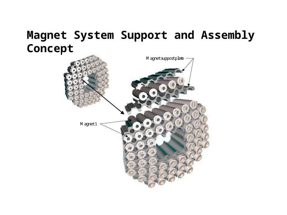
Magnet System Support and Assembly Concept
Magnet support plate
Magnet 1
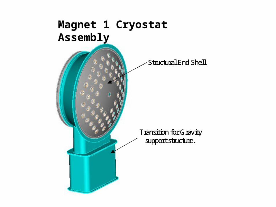
Structural End Shell
Transition for Gravity support structure.
Structural End Shell
Transition for Gravity support structure.
Magnet 1 Cryostat Assembly

Vortex-Tube Assembly
Magnet 1 Assembly
Magnets 2 and 3 Assembly
Magnet 4 Assemblies
Beam Tube Pumping Chamber
Beam Tube Pumping Chamber
Vortex-Tube Assembly
Magnet 1 Assembly
Magnets 2 and 3 Assembly
Magnet 4 Assemblies
Beam Tube Pumping Chamber
Beam Tube Pumping Chamber
Exploded View of the Final Focusing Magnet

Vortex-Tube Assembly
Magnet 1 Assembly
Magnets 2 and 3 Assembly
Magnet 4 Assemblies
Beam Tube Pumping Chamber Region
Vortex-Tube Assembly
Magnet 1 Assembly
Magnets 2 and 3 Assembly
Magnet 4 Assemblies
Beam Tube Pumping Chamber Region
Modular Breakdown of Final Focus Magnets

Final Focus Magnets Section Cut
Beam tube pumping region

RPD-2002 Power Plant Located in the ITER Building

Conclusion
• The RPD-2002 configuration is in its early stage of development with further design details, machine options and system trade-offs to be investigated.
• Maintainability issues need to be more fully understood from the point of view of component activation and personnel access.
• Design details of the beam tube pumping chambers need to be developed to assure pumping requirements are met and beam tube connections can be made.
• The details of the matching magnets will affect a the assembly process; consequently their integration into the design is needed.
Related Documents


![1 6/13/2015 ARIES PULSAR STARLITE Overview of ARIES Physics Studies ARIES-I, ARIES-II/IV, ARIES-III [D- 3 He], Pulsar, ARIES-RS, ARIES-ST, ARIES-AT presented.](https://static.cupdf.com/doc/110x72/56649d3e5503460f94a176ec/1-6132015-aries-pulsar-starlite-overview-of-aries-physics-studies-aries-i.jpg)