Review of technical drawing 1. Orthographic projection 2. Isometric projection 3. Sectioning 4. Dimensioning

Welcome message from author
This document is posted to help you gain knowledge. Please leave a comment to let me know what you think about it! Share it to your friends and learn new things together.
Transcript
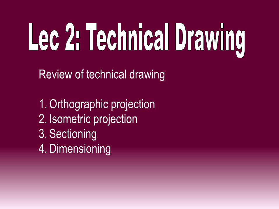
Review of technical drawing
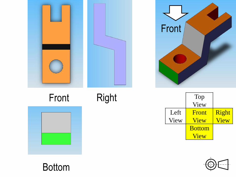
1. Orthographic projection
2. Isometric projection
3. Sectioning
4. Dimensioning
Bottom
Front Right
Front
Top
View
Left
View
Front
View
Right
View
Bottom
View
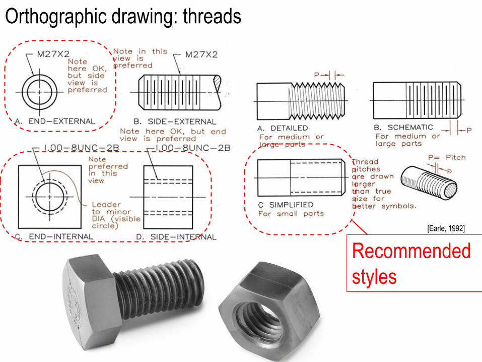
Orthographic drawing: threads
[Earle, 1992]
Recommended
styles
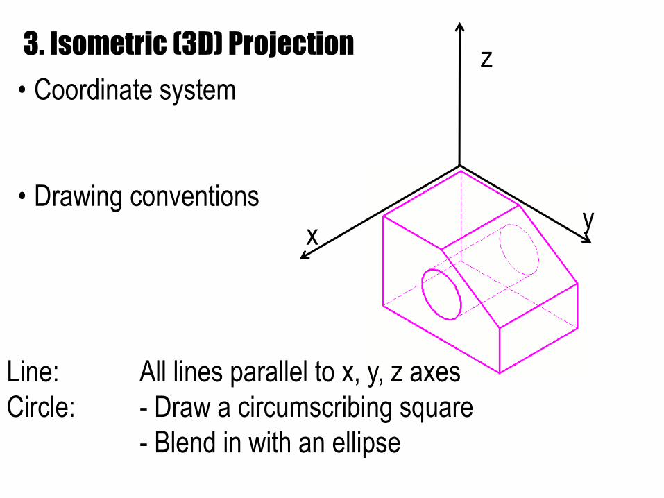
3. Isometric (3D) Projection
• Coordinate system
• Drawing conventions
Line: All lines parallel to x, y, z axes
Circle: - Draw a circumscribing square
- Blend in with an ellipse
x
z
y
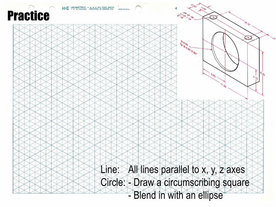
Practice
Line: All lines parallel to x, y, z axes
Circle: - Draw a circumscribing square
- Blend in with an ellipse
x
z
y
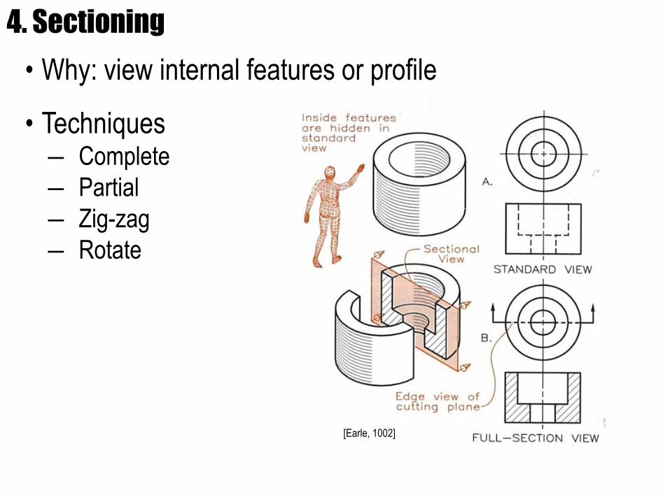
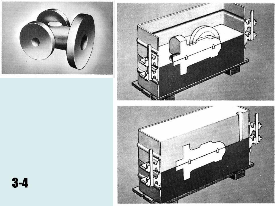
4. Sectioning
• Why: view internal features or profile
• Techniques― Complete
― Partial
― Zig-zag
― Rotate
[Earle, 1002]
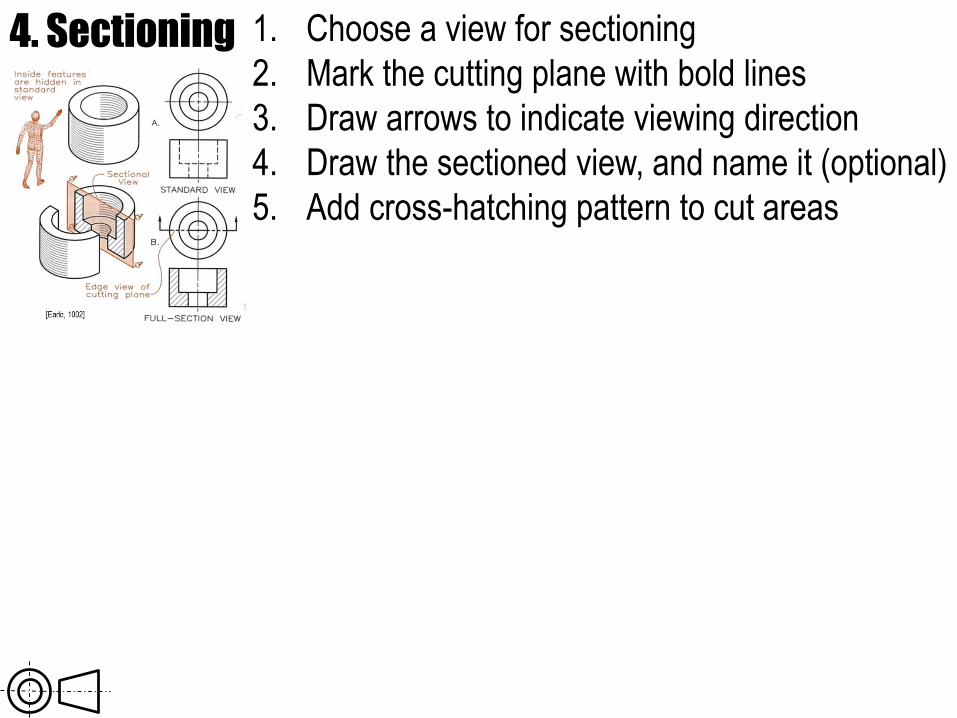
4. Sectioning 1. Choose a view for sectioning
2. Mark the cutting plane with bold lines
3. Draw arrows to indicate viewing direction
4. Draw the sectioned view, and name it (optional)
5. Add cross-hatching pattern to cut areas
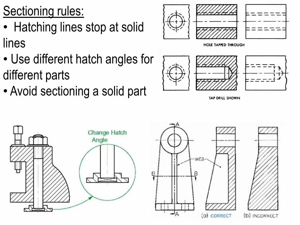
Sectioning rules:
• Hatching lines stop at solid
lines
• Use different hatch angles for
different parts
• Avoid sectioning a solid part
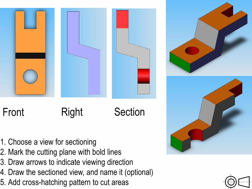
Front Right Section
1. Choose a view for sectioning
2. Mark the cutting plane with bold lines
3. Draw arrows to indicate viewing direction
4. Draw the sectioned view, and name it (optional)
5. Add cross-hatching pattern to cut areas
3-4
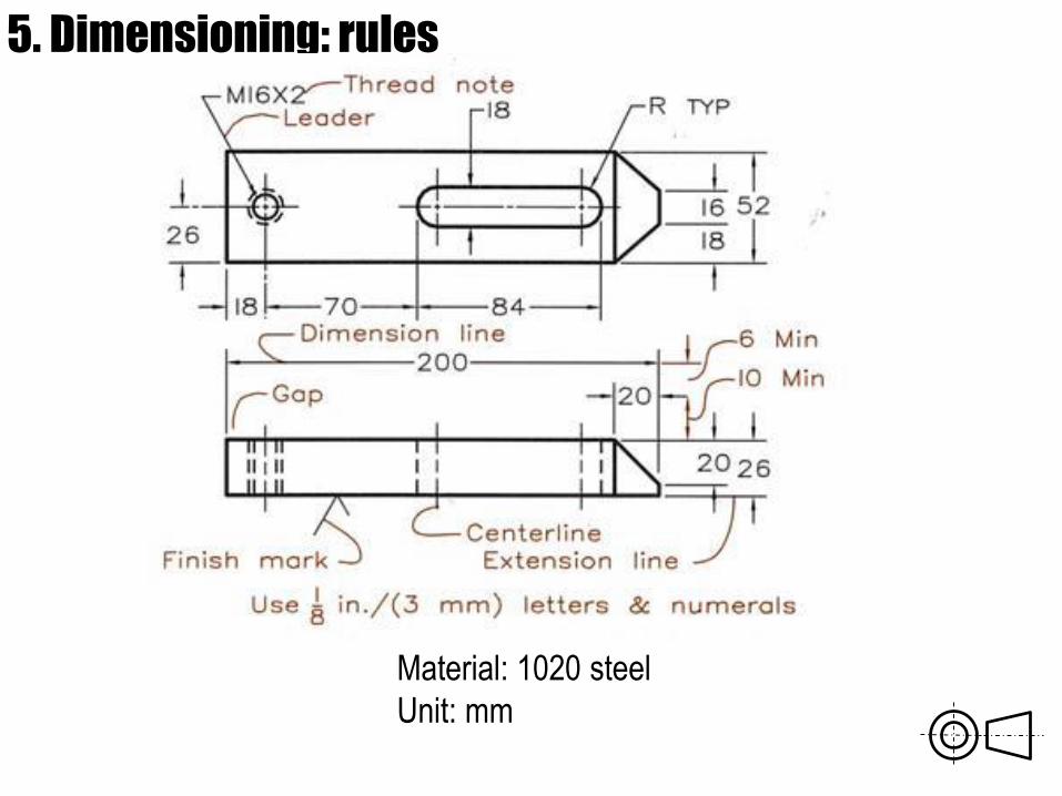
5. Dimensioning: rules
Material: 1020 steel
Unit: mm
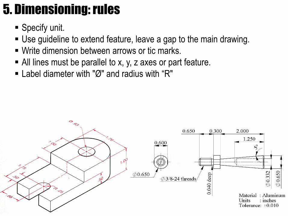
5. Dimensioning: rules
Specify unit.
Use guideline to extend feature, leave a gap to the main drawing.
Write dimension between arrows or tic marks.
All lines must be parallel to x, y, z axes or part feature.
Label diameter with "Ø" and radius with “R"
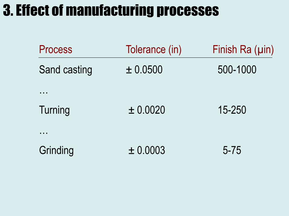
3. Effect of manufacturing processes
Process Tolerance (in) Finish Ra (µin)
Sand casting ± 0.0500 500-1000
…
Turning ± 0.0020 15-250
…
Grinding ± 0.0003 5-75
Source:
http://www.starrett.com/
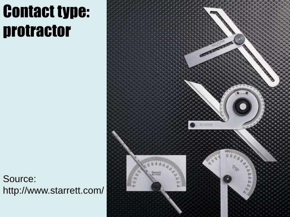
Contact type:
protractor
Source: http://www.starrett.com/
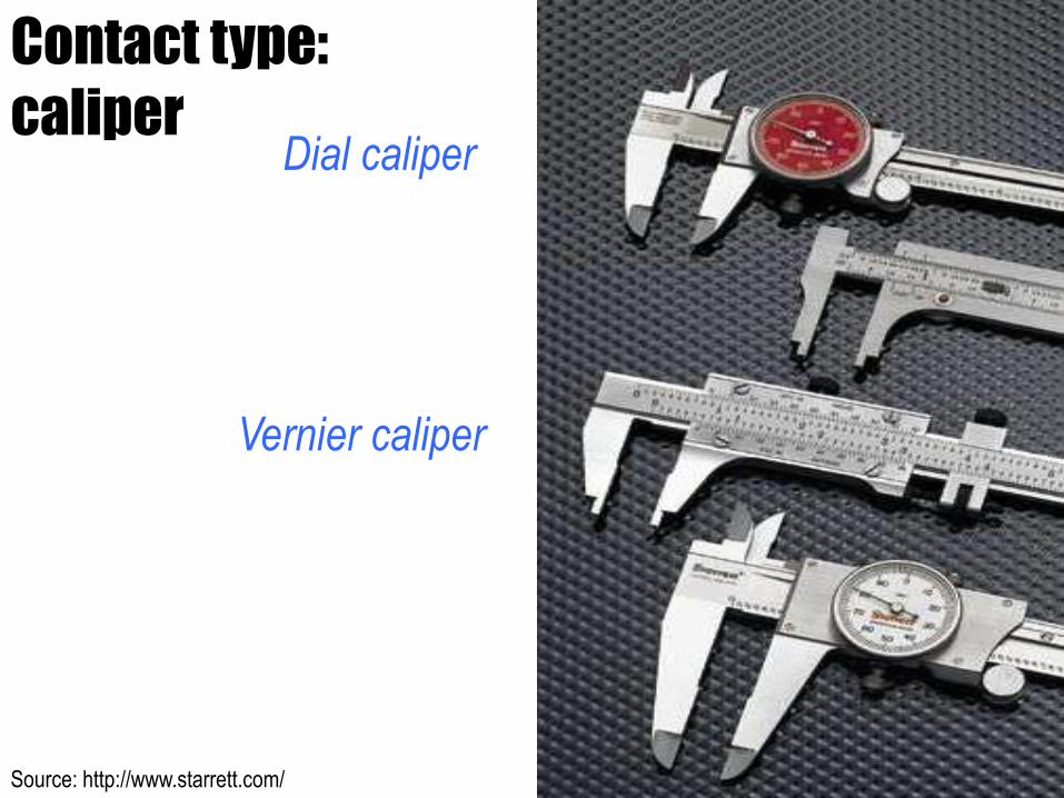
Contact type:
caliperDial caliper
Vernier caliper
Source: http://www.starrett.com/
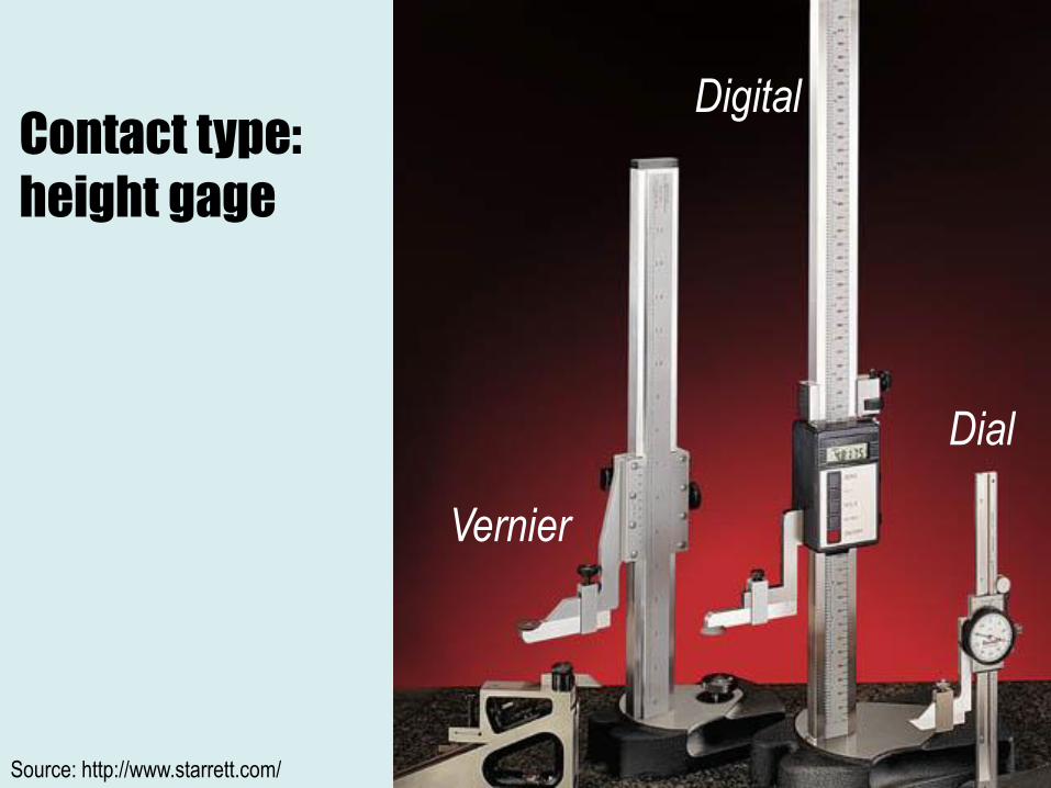
Contact type:
height gage
Vernier
Digital
Dial
Source: http://www.starrett.com/
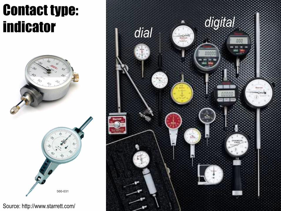
Contact type:
indicator dialdigital
Source: http://www.starrett.com/
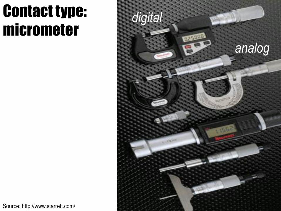
Contact type:
micrometerdigital
analog
Source: http://mitutoyo.com
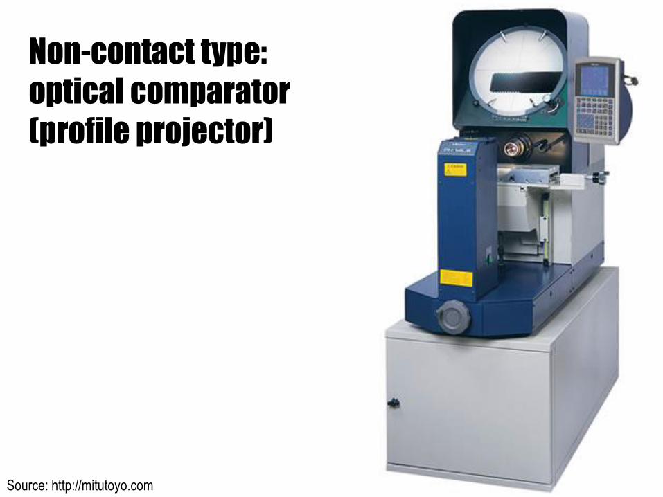
Non-contact type:
optical comparator
(profile projector)
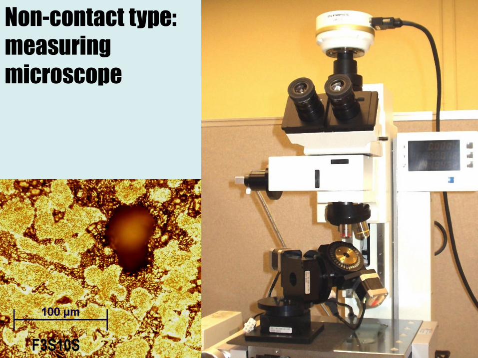
Non-contact type:
measuring
microscope
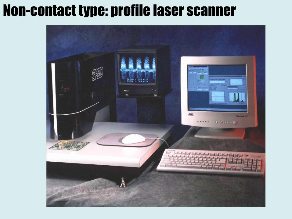
Non-contact type: profile laser scanner
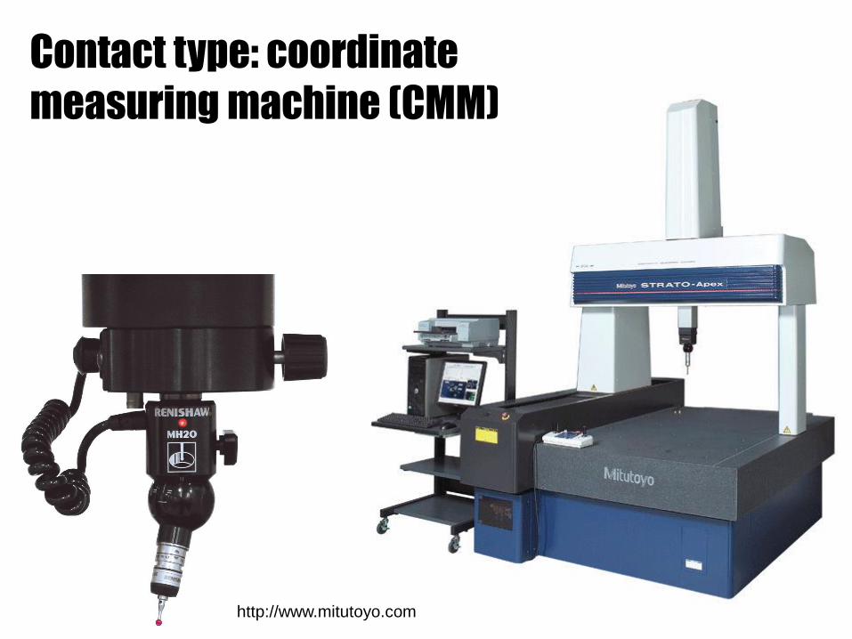
Contact type: coordinate
measuring machine (CMM)
http://www.mitutoyo.com
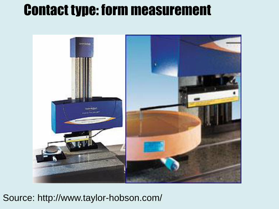
Source: http://www.taylor-hobson.com/
Contact type: form measurement
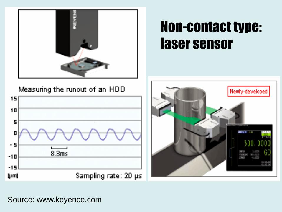
Source: www.keyence.com
Non-contact type:
laser sensor
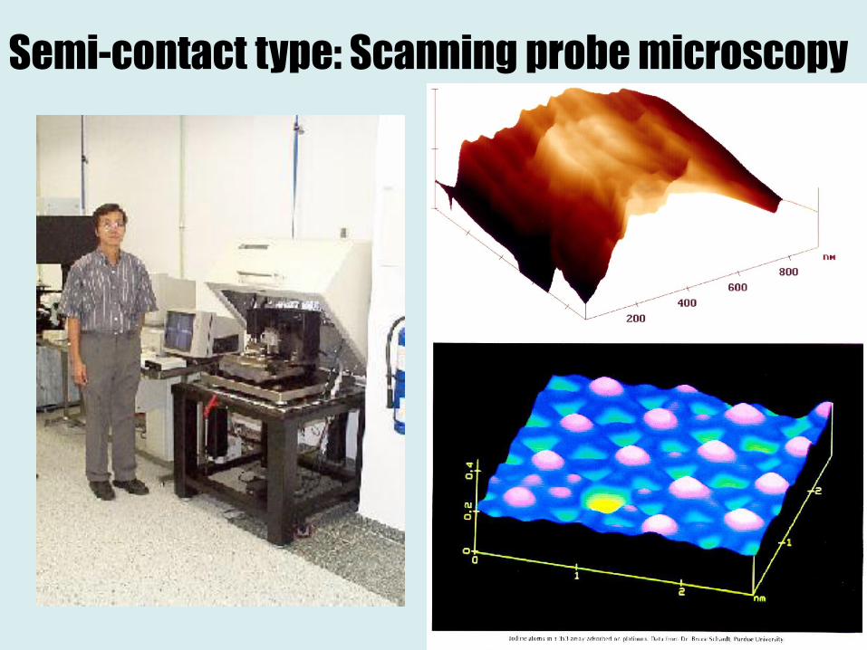
Semi-contact type: Scanning probe microscopy
Source: http://www.mitutoyo.com/
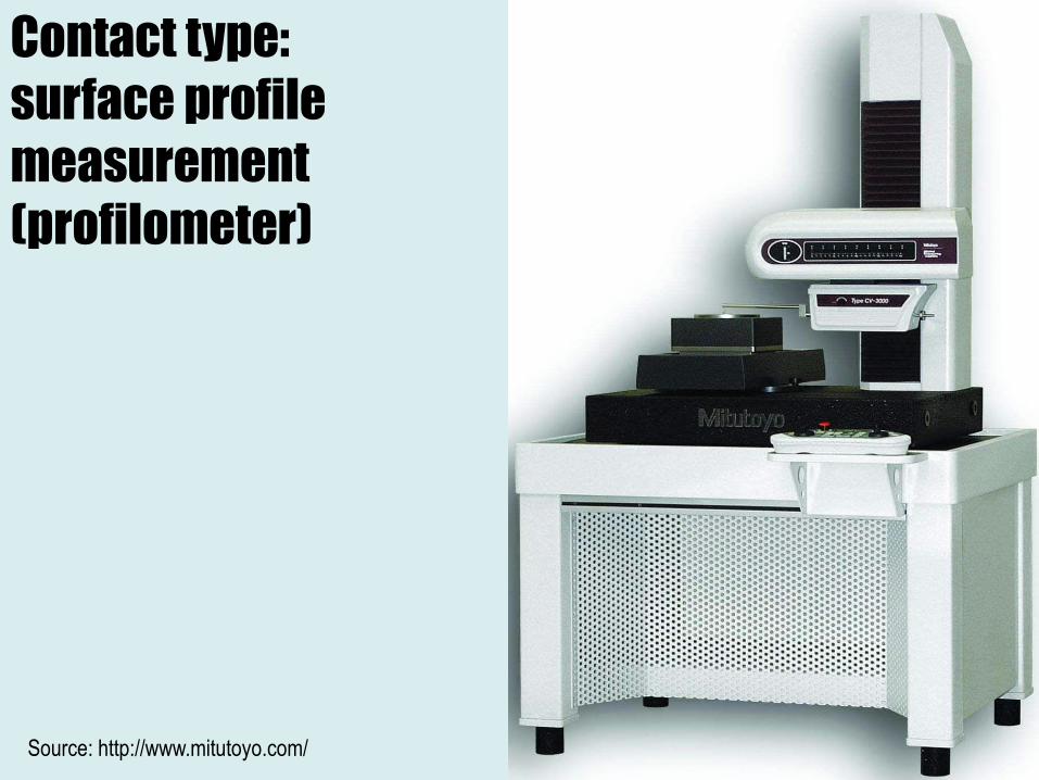
Contact type:
surface profile
measurement
(profilometer)

Equipment
Contact type:
Profilometer
26
[www.processinstruments.ca]
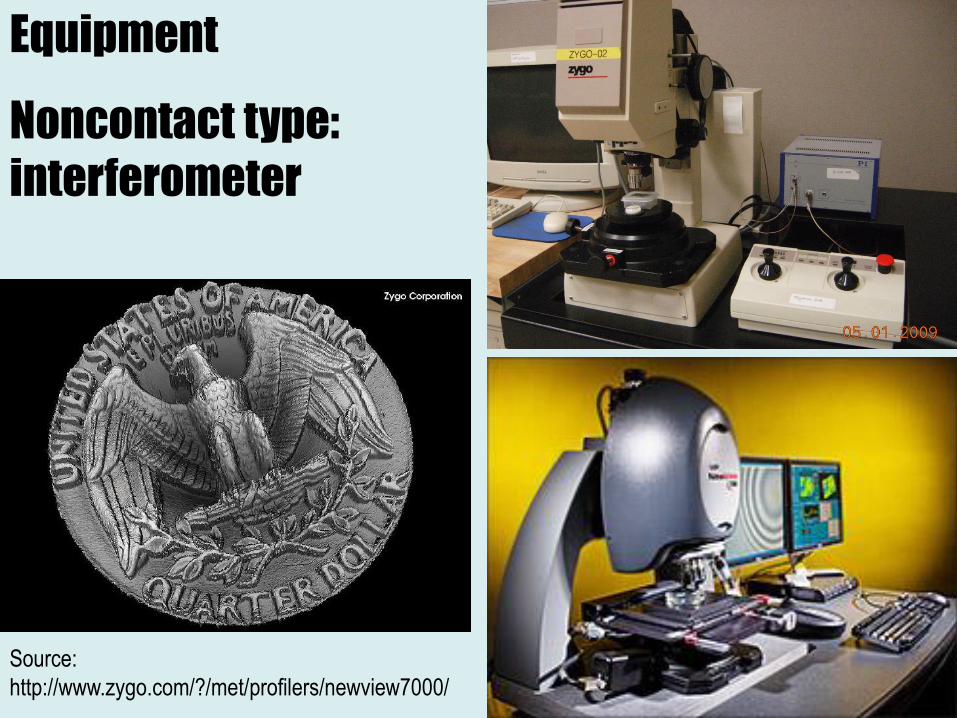
Source:
http://www.zygo.com/?/met/profilers/newview7000/
Equipment
Noncontact type:
interferometer
27
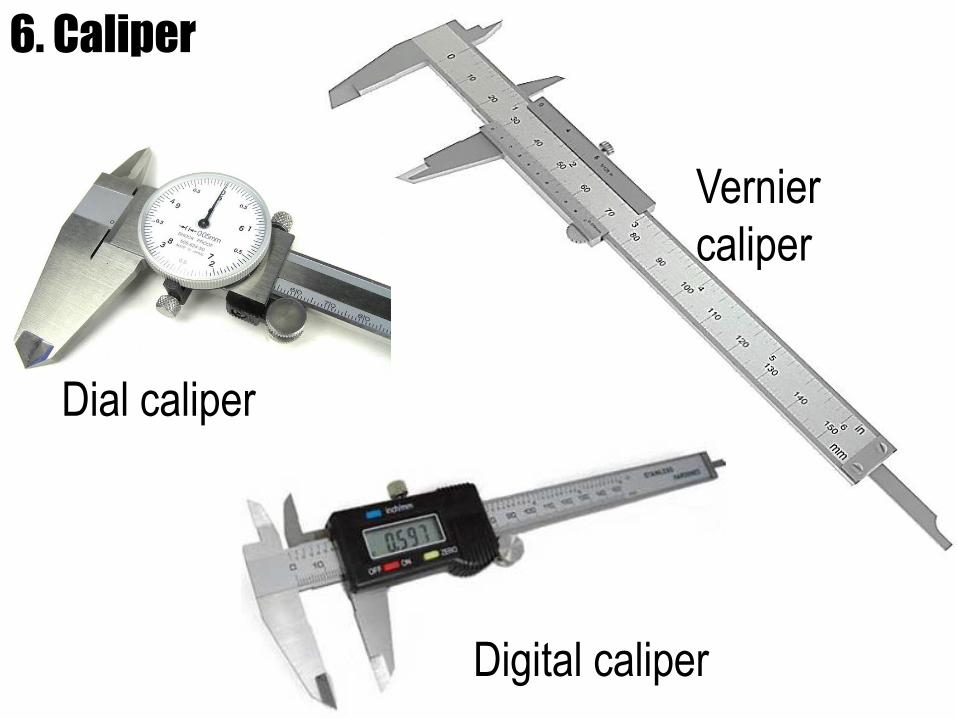
Vernier
caliper
Dial caliper
Digital caliper
6. Caliper
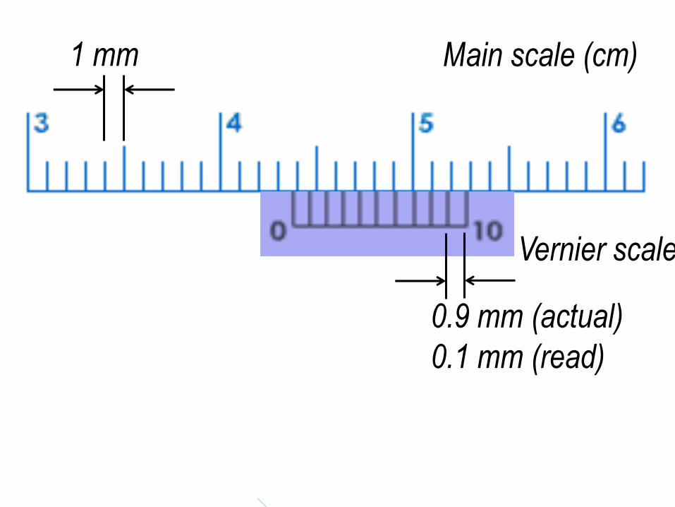
Main scale (cm)
Vernier scale
1 mm
0.9 mm (actual)
0.1 mm (read)
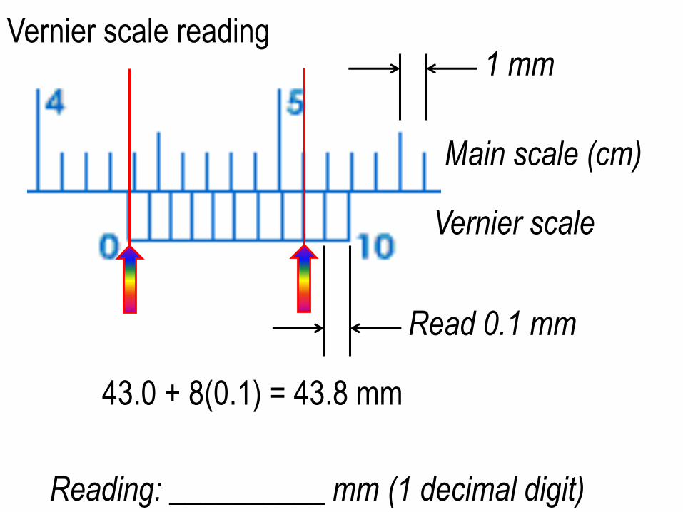
Vernier scale reading
Reading: __________ mm (1 decimal digit)
Vernier scale
1 mm
Main scale (cm)
Read 0.1 mm
43.0 + 8(0.1) = 43.8 mm
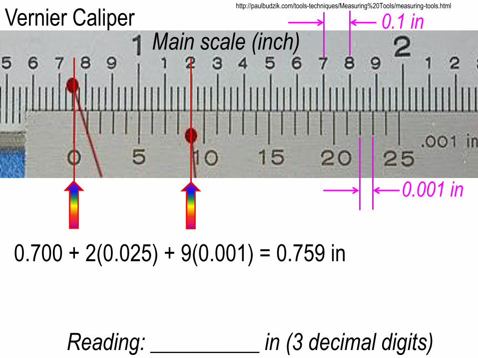
Vernier Caliper
Reading: __________ in (3 decimal digits)
http://paulbudzik.com/tools-techniques/Measuring%20Tools/measuring-tools.html
Main scale (inch)
0.700 + 2(0.025) + 9(0.001) = 0.759 in
0.1 in
0.001 in
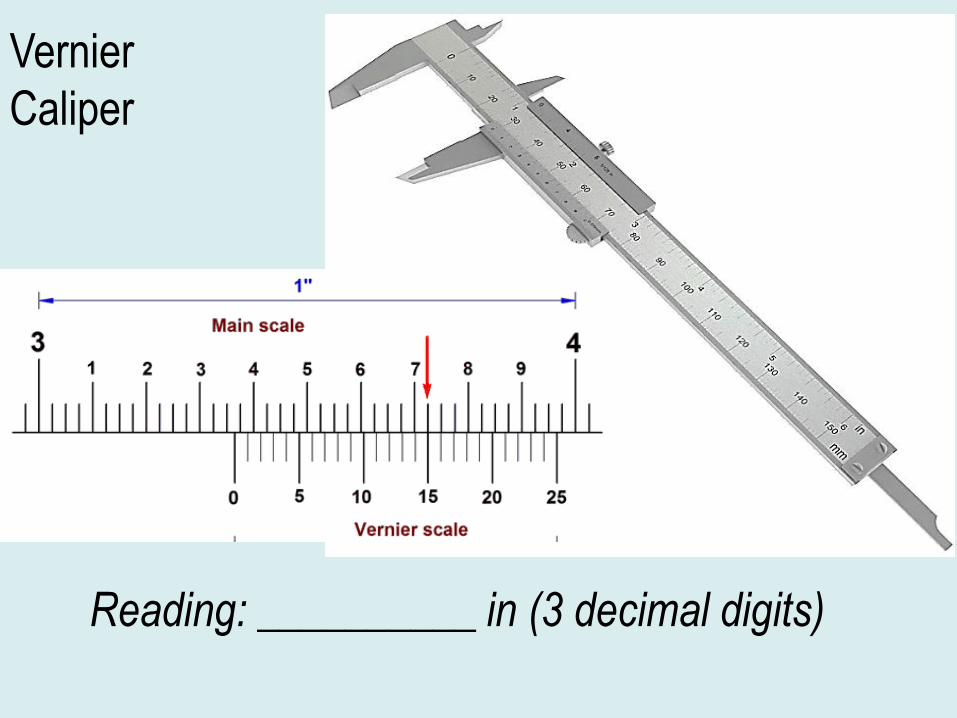
Vernier
Caliper
Reading: __________ in (3 decimal digits)
Rakuten.com
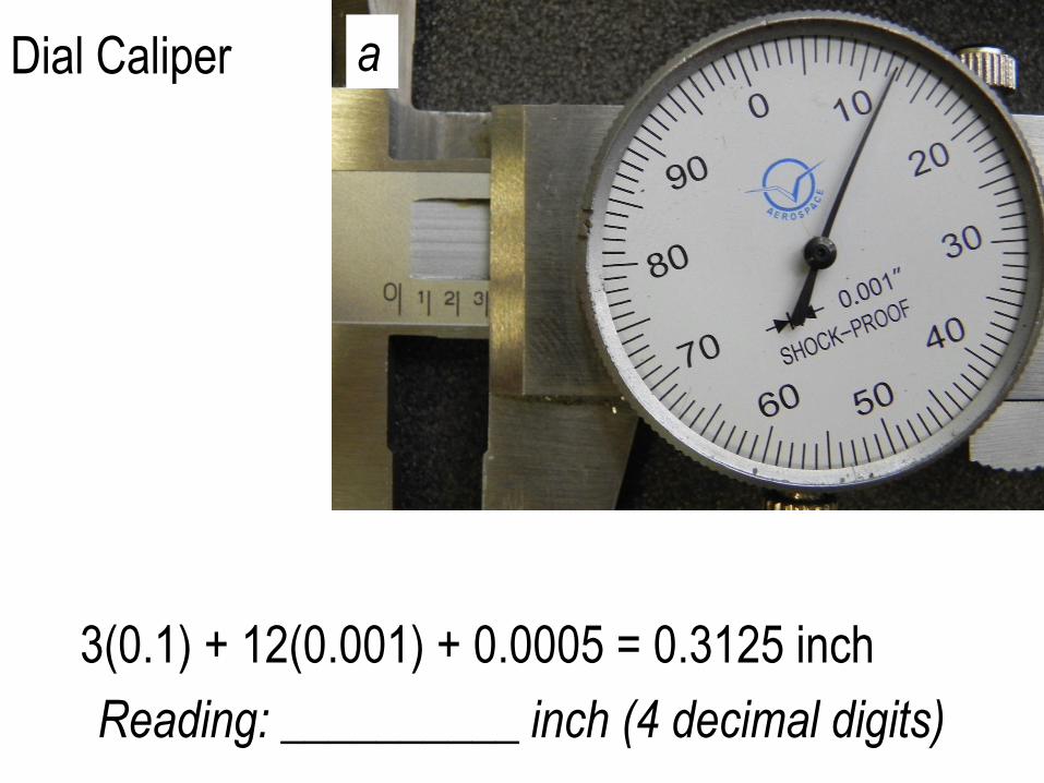
Dial Caliper
Reading: __________ inch (4 decimal digits)
a
3(0.1) + 12(0.001) + 0.0005 = 0.3125 inch
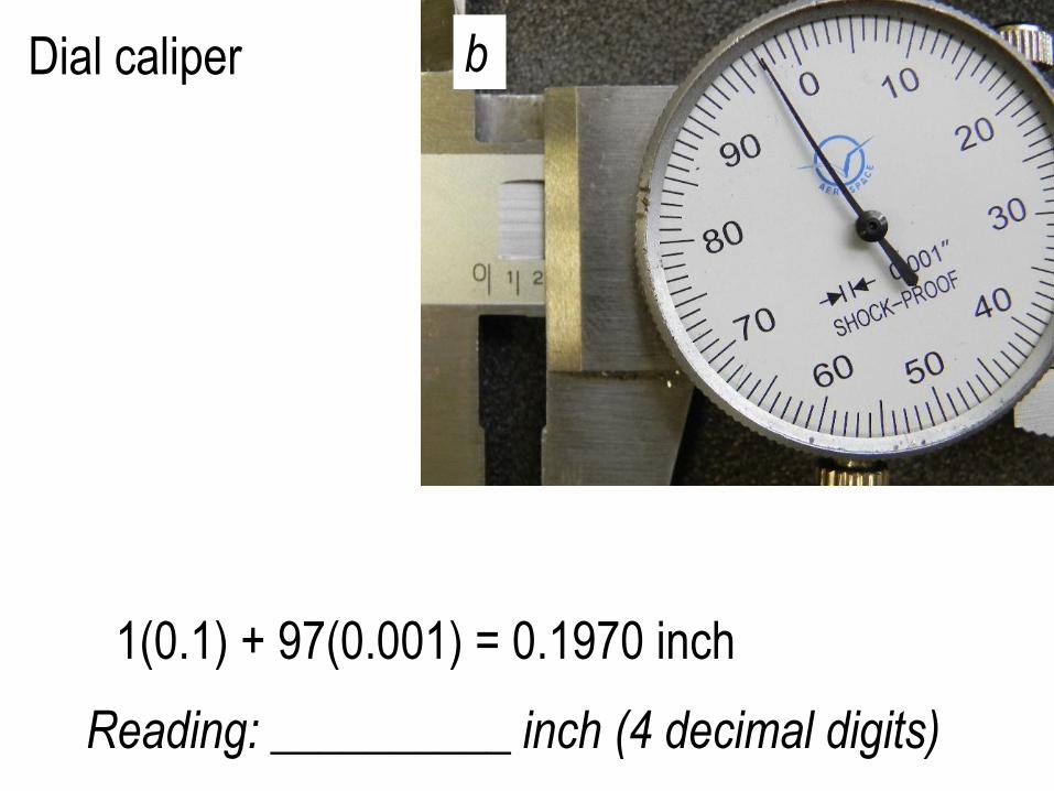
Dial caliper
Reading: __________ inch (4 decimal digits)
b
1(0.1) + 97(0.001) = 0.1970 inch
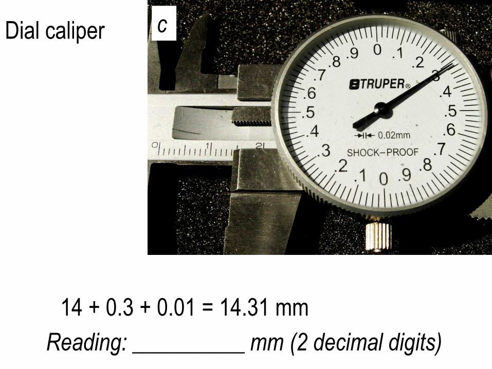
Dial caliper
Reading: __________ mm (2 decimal digits)
c
14 + 0.3 + 0.01 = 14.31 mm
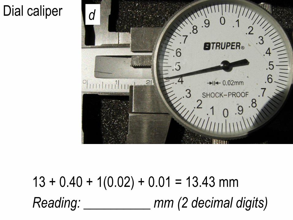
Dial caliper
Reading: __________ mm (2 decimal digits)
d
13 + 0.40 + 1(0.02) + 0.01 = 13.43 mm
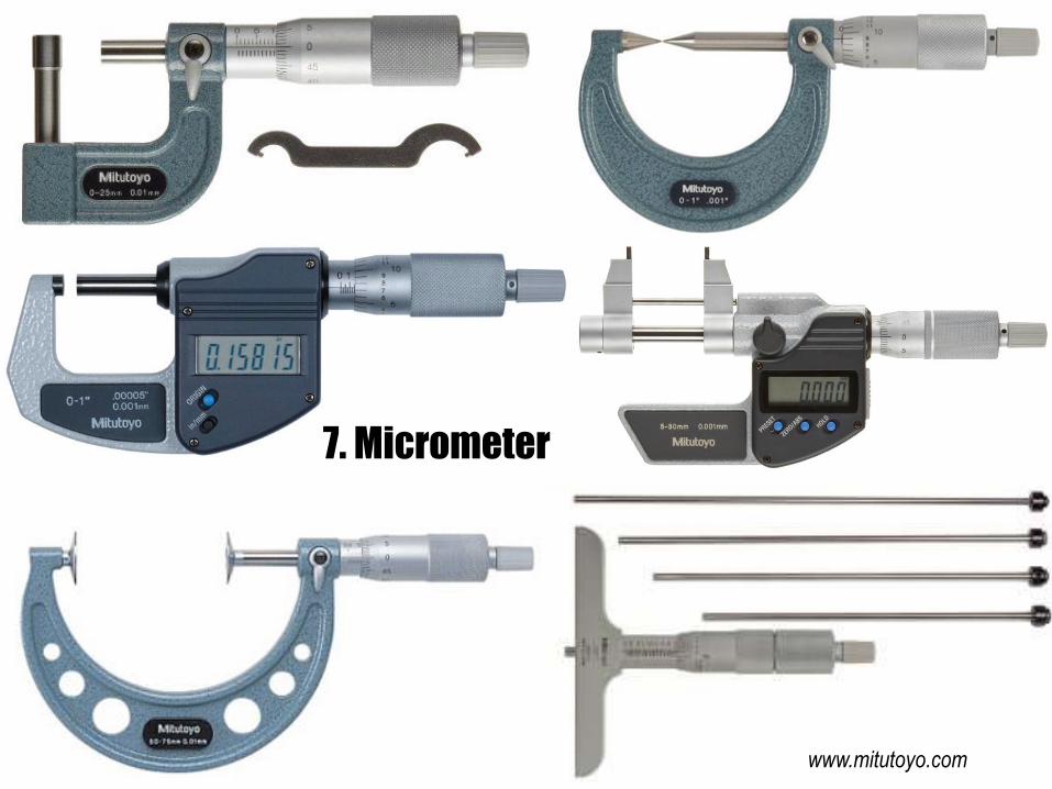
7. Micrometer
www.mitutoyo.com
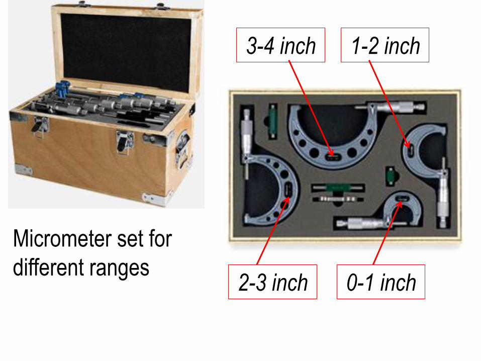
Micrometer set for
different ranges0-1 inch
1-2 inch
2-3 inch
3-4 inch
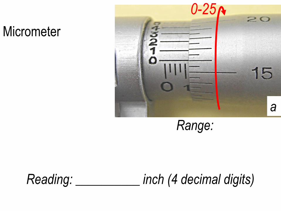
Micrometer
Range:
0-25
a
Reading: __________ inch (4 decimal digits)
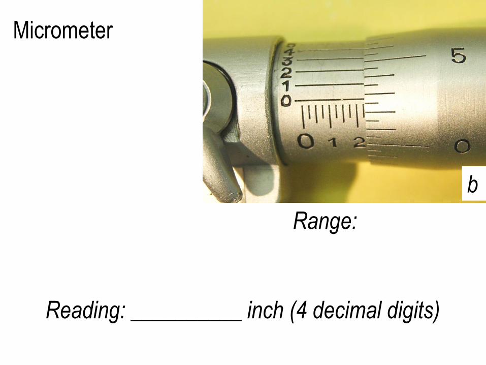
Micrometer
Range:
b
Reading: __________ inch (4 decimal digits)
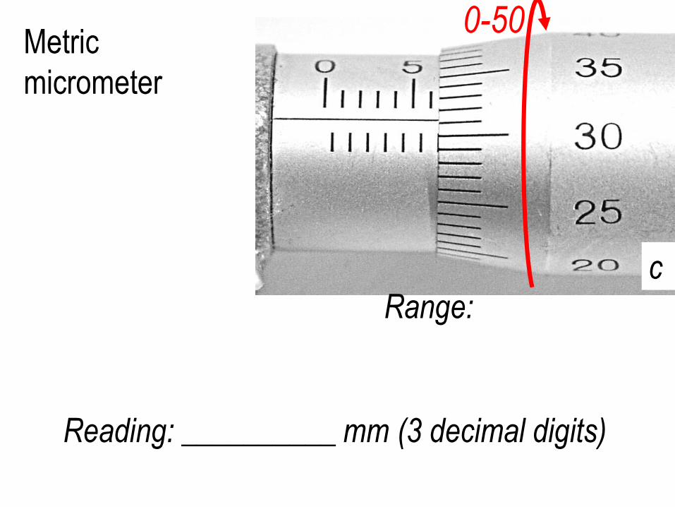
Metric
micrometer
Range:
0-50
c
Reading: __________ mm (3 decimal digits)
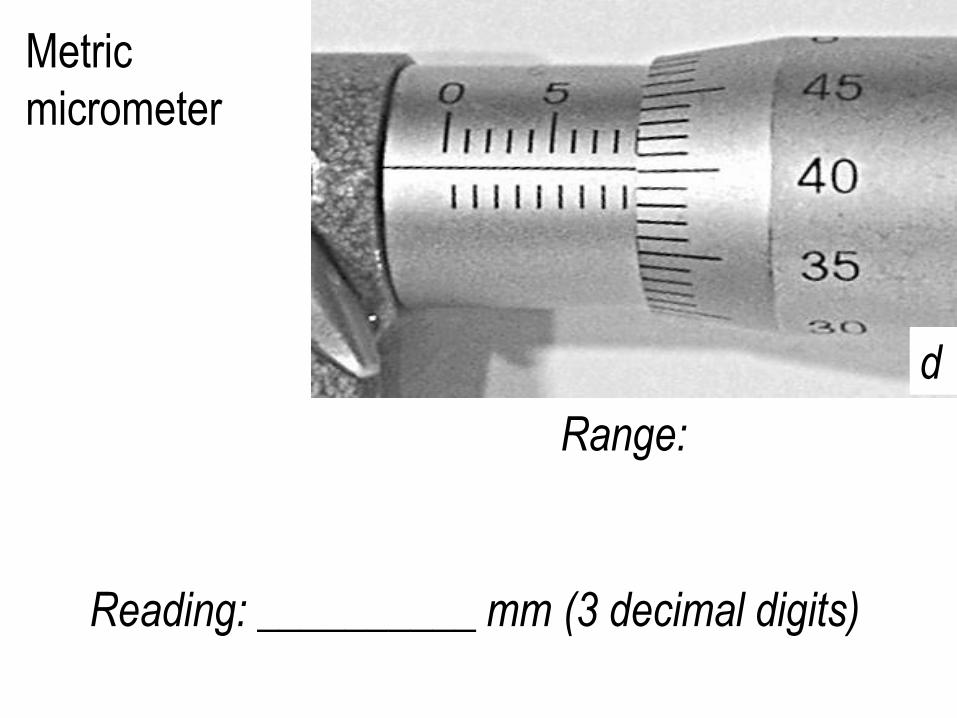
Metric
micrometer
Range:
d
Reading: __________ mm (3 decimal digits)
http://www.linnbenton.edu/auto/day/mike/vernier3.html
http://www.pastaffing.com/trainmic.asp
http://cf.linnbenton.edu/eit/auto/krolicp/web.cfm?pgID=2262
http://www.wisc-online.com
/Objects/ViewObject.aspx?ID=MTL1902
1) DVD (comes with the reference textbook)
2) Lab practice
3) Homework
4) Online practice
Micrometer Reading
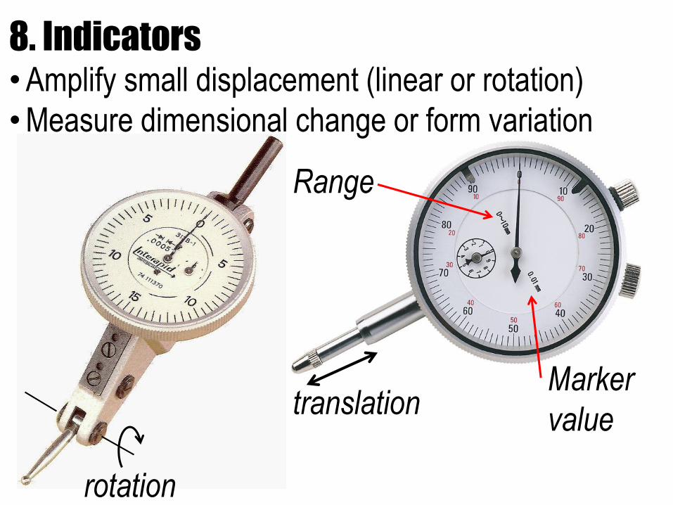
8. Indicators•Amplify small displacement (linear or rotation)
•Measure dimensional change or form variation
Range
Marker
valuetranslation
rotation
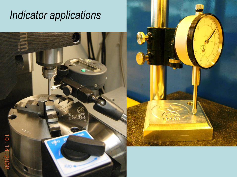
Indicator applications
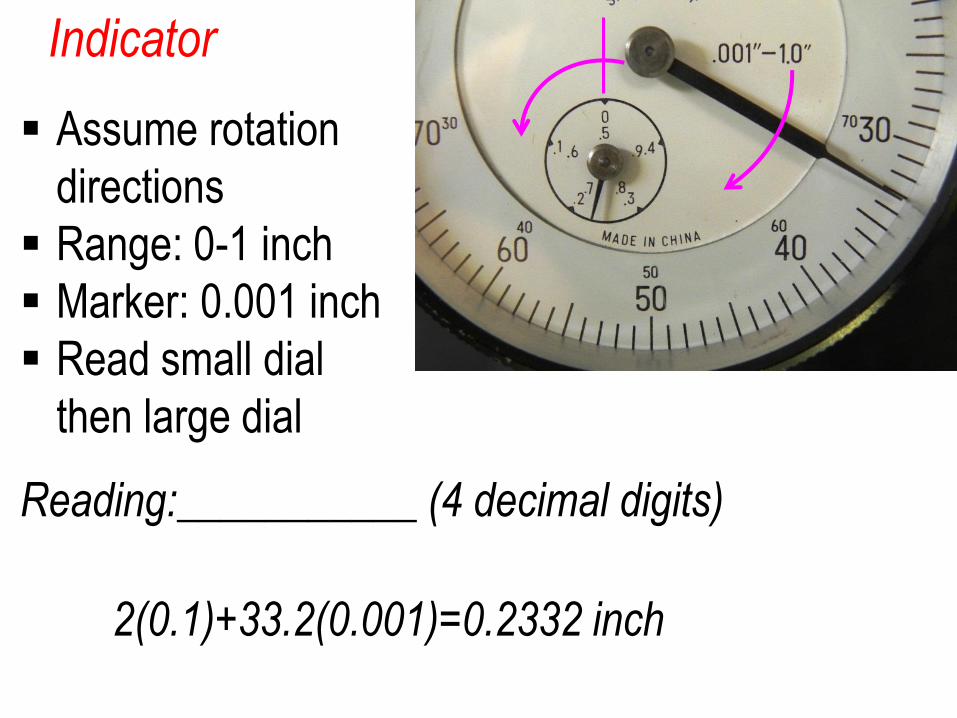
Indicator
Reading:___________ (4 decimal digits)
Assume rotation
directions
Range: 0-1 inch
Marker: 0.001 inch
Read small dial
then large dial
2(0.1)+33.2(0.001)=0.2332 inch
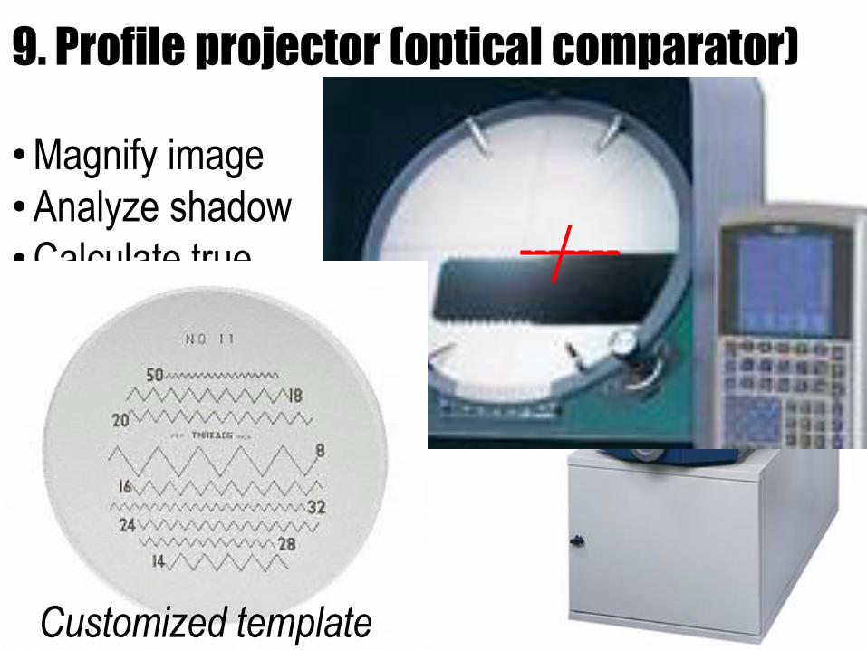
9. Profile projector (optical comparator)
•Magnify image
•Analyze shadow
•Calculate true
dimensions
• Limit to 2D profile
Customized template
www.craftsmanspace.com
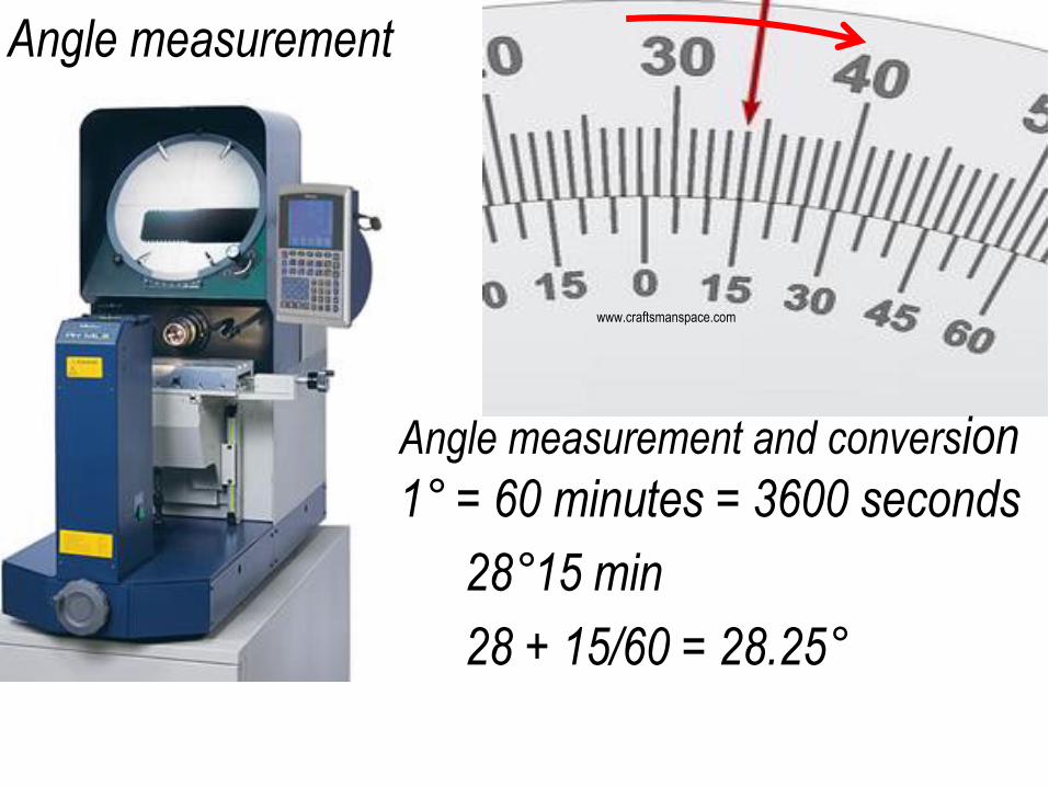
Angle measurement
28°15 min
28 + 15/60 = 28.25°
Angle measurement and conversion
1° = 60 minutes = 3600 seconds
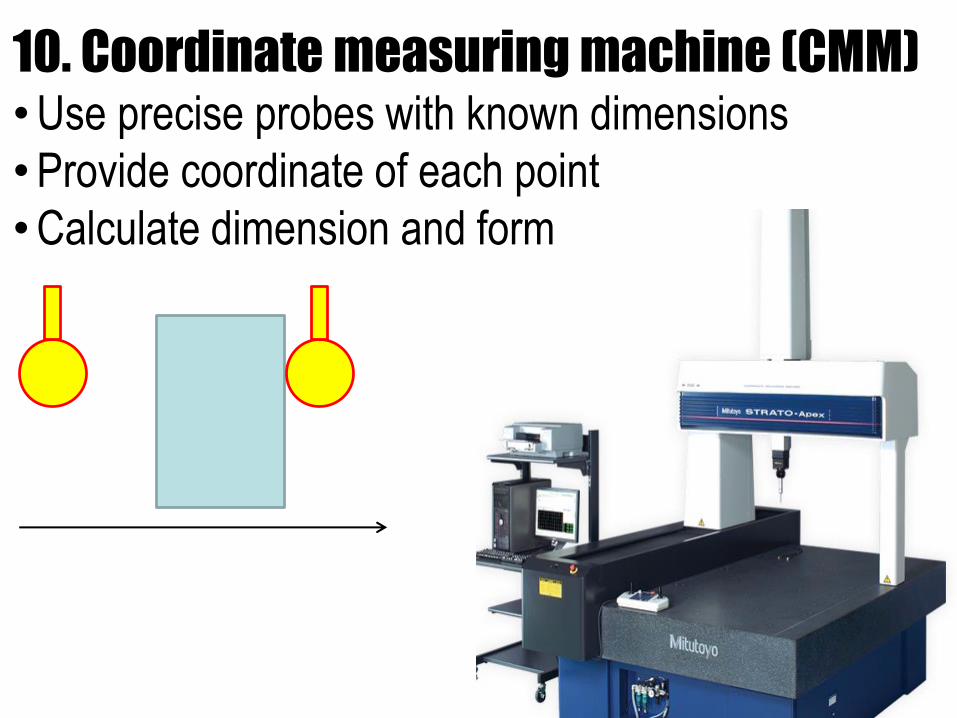
10. Coordinate measuring machine (CMM)•Use precise probes with known dimensions
•Provide coordinate of each point
•Calculate dimension and form
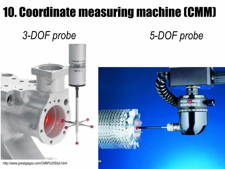
10. Coordinate measuring machine (CMM)
http://www.greatgages.com/CMM%20Styli.htmlcoordinate-measuring-machine.net
3-DOF probe 5-DOF probe
1) Nature of material
2) Mechanical properties
3) Effect of temperature
4) Metals
5) Polymers
6) Material comparison
7) Effect on manufacturing
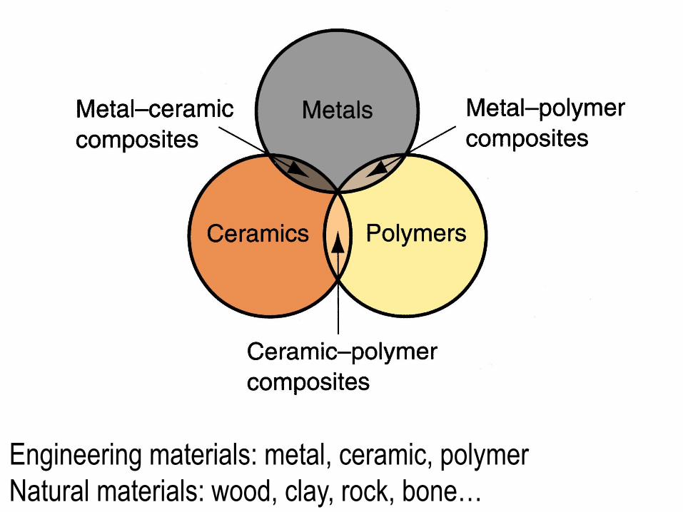
Engineering materials: metal, ceramic, polymer
Natural materials: wood, clay, rock, bone…

AtomAtom= nucleus + electrons
Bonds: strong primary:
weak secondary:
Break bonds→ release atoms (machining)
1. Nature of material
http://www.vtaide.com/png/atom.htm
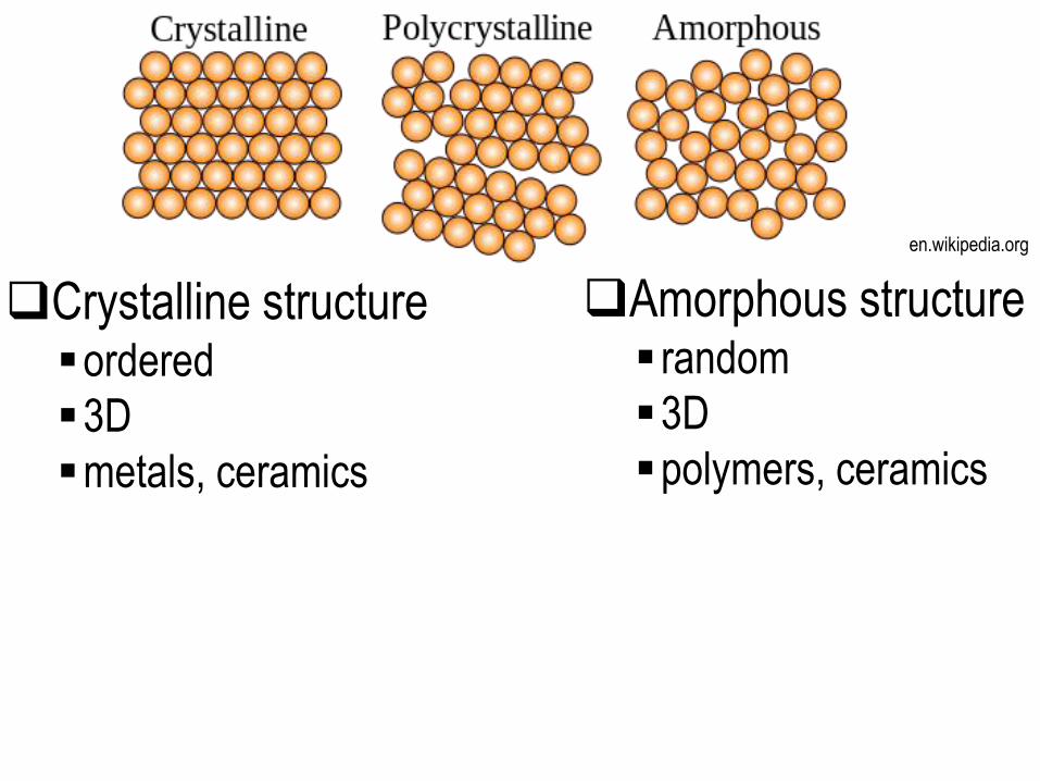
Crystalline structureordered
3D
metals, ceramics
en.wikipedia.org
Amorphous structure random
3D
polymers, ceramics
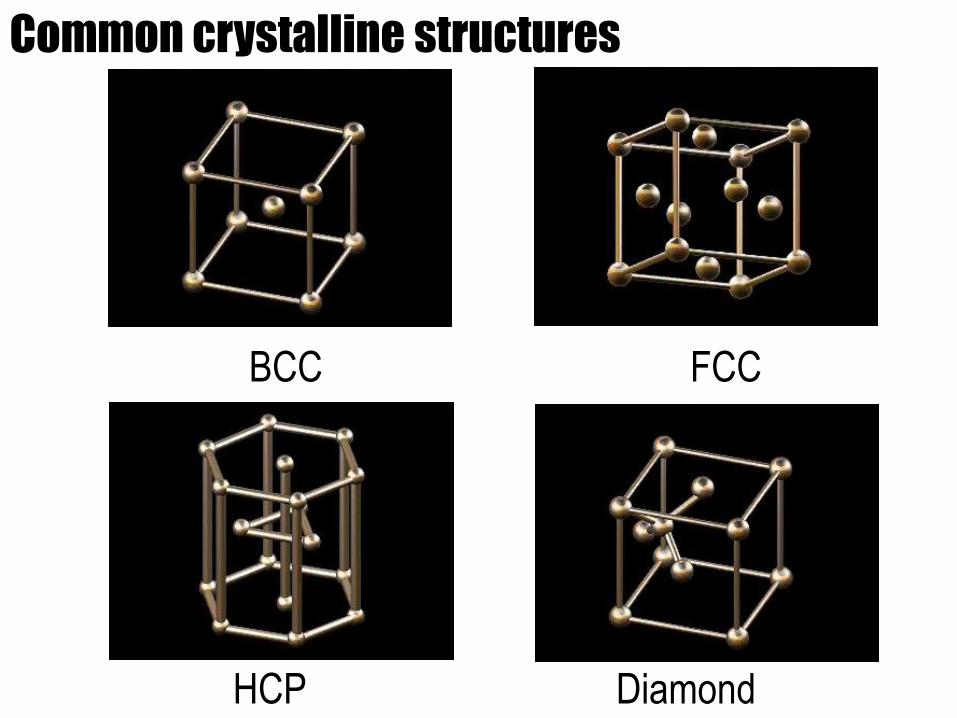
Common crystalline structures
BCC FCC
HCP Diamond
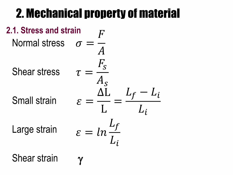
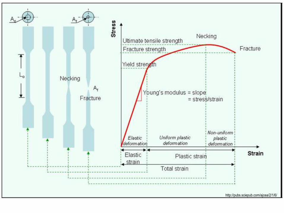
2. Mechanical property of material
2.1. Stress and strain
Normal stress
Shear stress
Small strain
Large strain
Shear strain
𝜎 =𝐹
𝐴
𝜏 =𝐹𝑠𝐴𝑠
𝜀 =ΔL
L=𝐿𝑓 − 𝐿𝑖
𝐿𝑖
𝜀 = 𝑙𝑛𝐿𝑓
𝐿𝑖
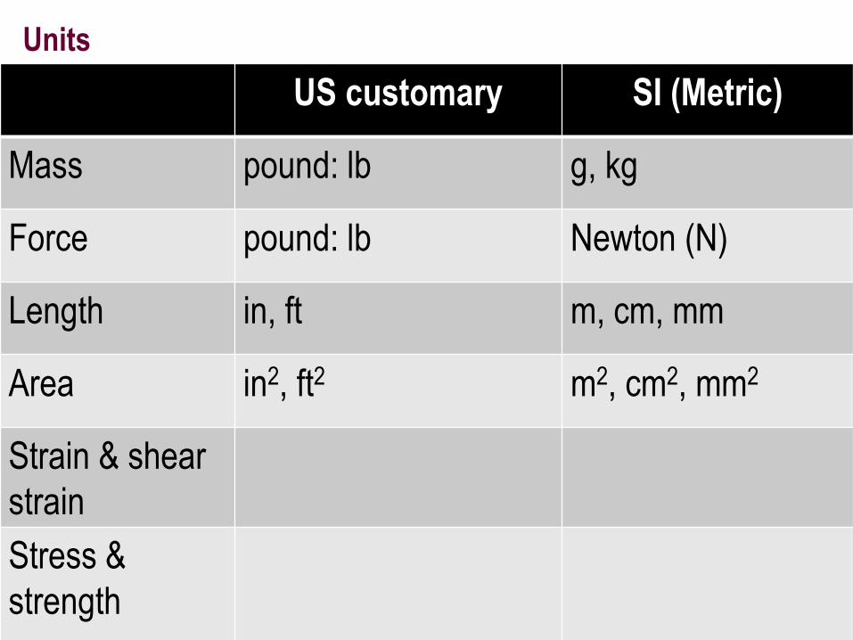
Units
US customary SI (Metric)
Mass pound: lb g, kg
Force pound: lb Newton (N)
Length in, ft m, cm, mm
Area in2, ft2 m2, cm2, mm2
Strain & shear
strain
Stress &
strength
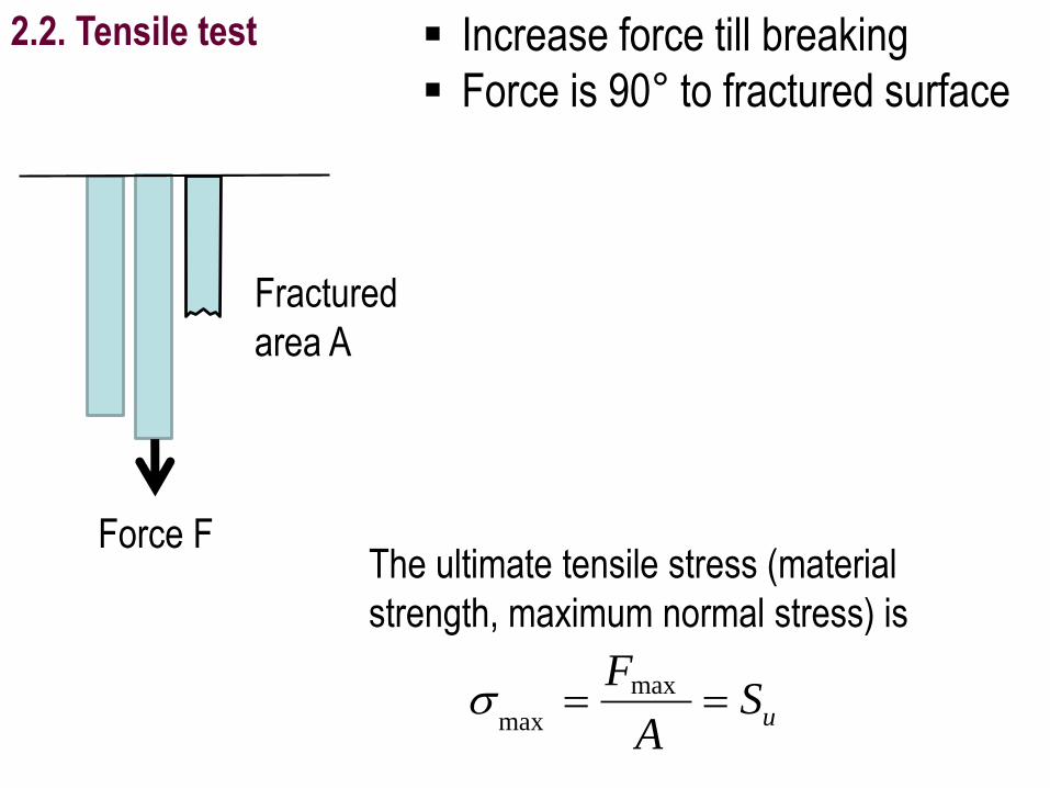
Force FThe ultimate tensile stress (material
strength, maximum normal stress) is
uSA
F max
max
2.2. Tensile test Increase force till breaking
Force is 90° to fractured surface
Fractured
area A
http://pubs.sciepub.com/ajcea/2/1/6/
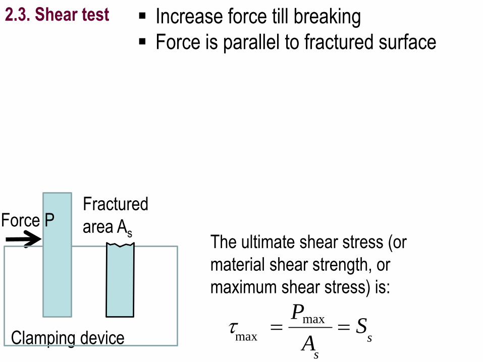
Fractured
area As The ultimate shear stress (or
material shear strength, or
maximum shear stress) is:
s
s
SA
P max
max
Clamping device
2.3. Shear test Increase force till breaking
Force is parallel to fractured surface
Force P
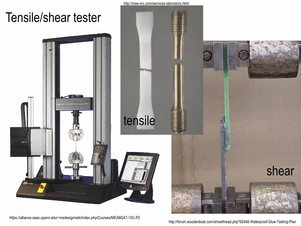
https://alliance.seas.upenn.edu/~medesign/wiki/index.php/Courses/MEAM247-10C-P2
Tensile/shear tester
http://forum.woodenboat.com/showthread.php?92446-Waterproof-Glue-Testing-Plan
shear
tensile
http://mee-inc.com/services-laboratory.html
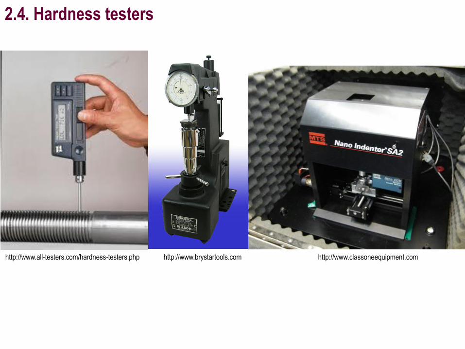
2.4. Hardness testers
http://www.all-testers.com/hardness-testers.php http://www.classoneequipment.comhttp://www.brystartools.com
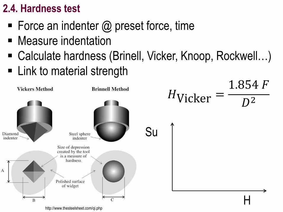
2.4. Hardness test
Force an indenter @ preset force, time
Measure indentation
Calculate hardness (Brinell, Vicker, Knoop, Rockwell…)
Link to material strength
http://www.thesteelsheet.com/qi.php
𝐻Vicker =1.854 𝐹
𝐷2
Su
H
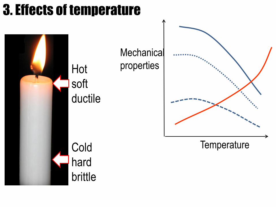
3. Effects of temperature
Hot
soft
ductile
Cold
hard
brittle
Mechanical
properties
Temperature
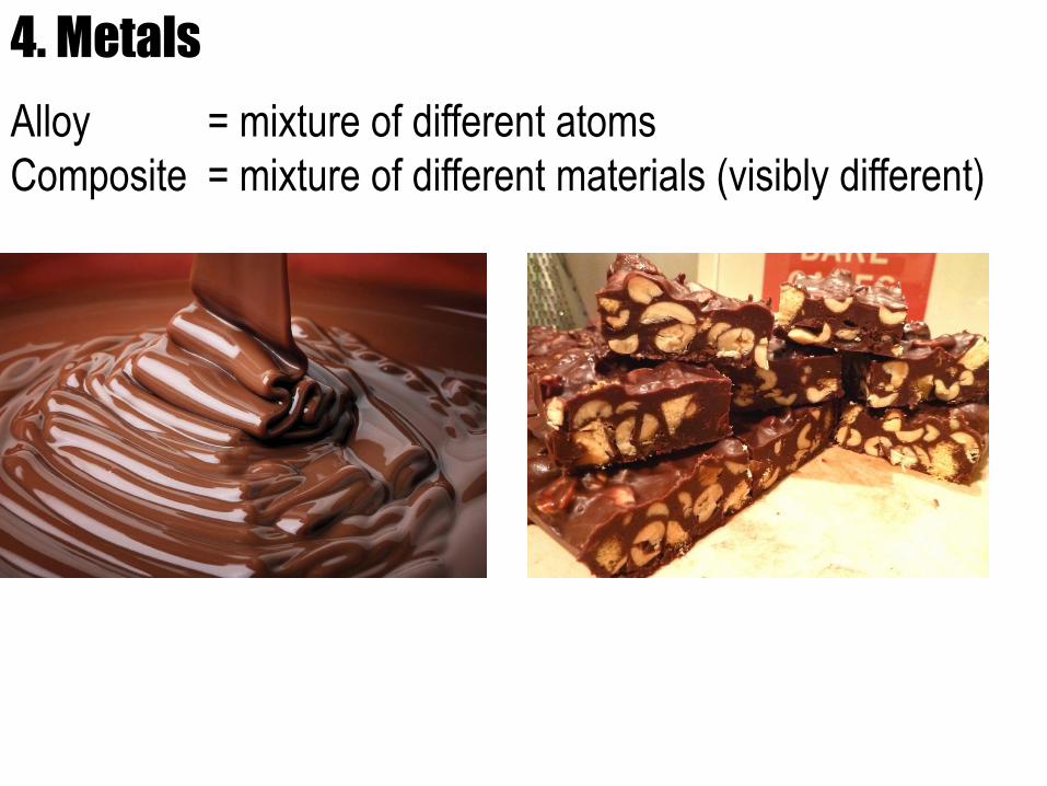
4. Metals
Alloy = mixture of different atoms
Composite = mixture of different materials (visibly different)
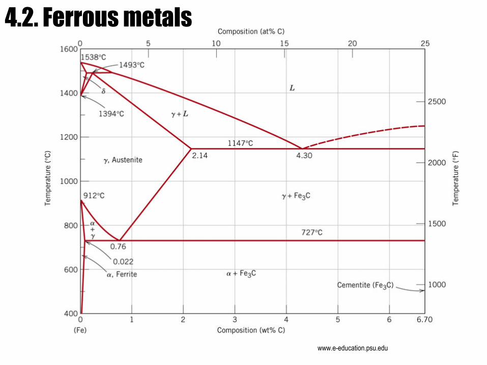
4.2. Ferrous metals
www.e-education.psu.edu
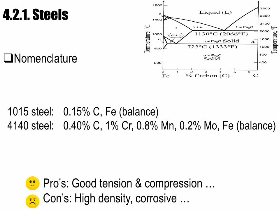
4.2.1. Steels
1015 steel: 0.15% C, Fe (balance)
4140 steel: 0.40% C, 1% Cr, 0.8% Mn, 0.2% Mo, Fe (balance)
Nomenclature
Pro’s: Good tension & compression …
Con’s: High density, corrosive …
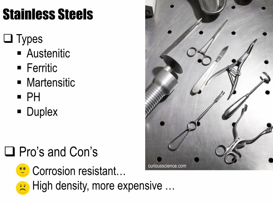
Stainless Steels
Types
Austenitic
Ferritic
Martensitic
PH
Duplex
Corrosion resistant…
High density, more expensive …
www.hellotrade.com
curiousscience.com
Pro’s and Con’s
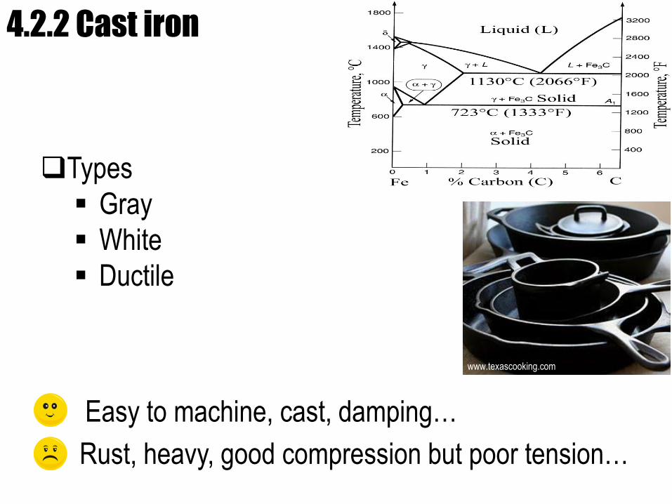
4.2.2 Cast iron
Easy to machine, cast, damping…
Rust, heavy, good compression but poor tension…
Types
Gray
White
Ductile
www.texascooking.com
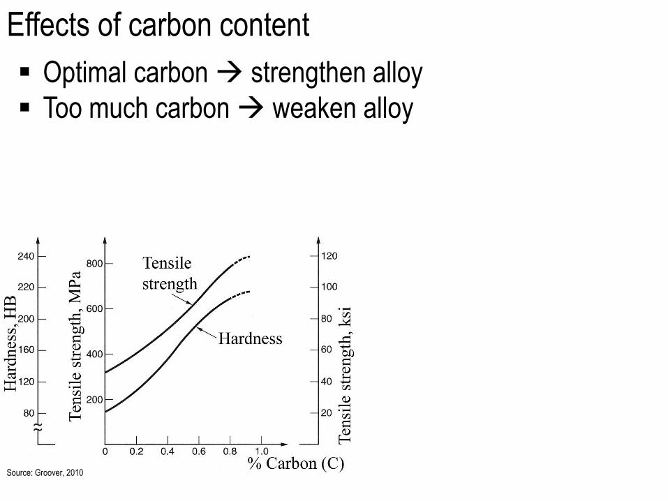
Effects of carbon content
Optimal carbon strengthen alloy
Too much carbon weaken alloy
Source: Groover, 2010
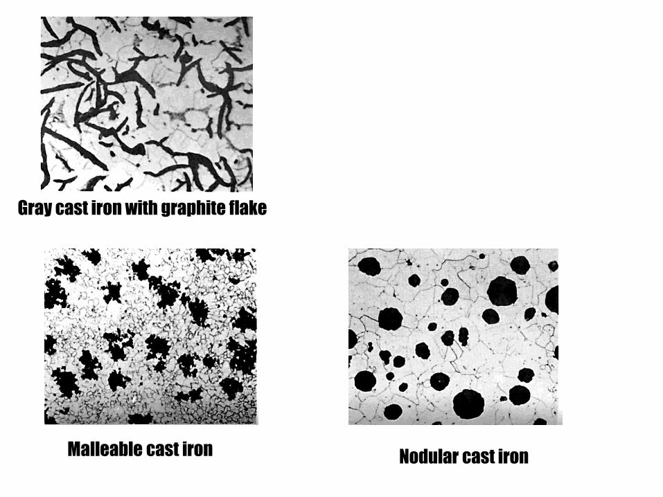
Malleable cast iron Nodular cast iron
Gray cast iron with graphite flake
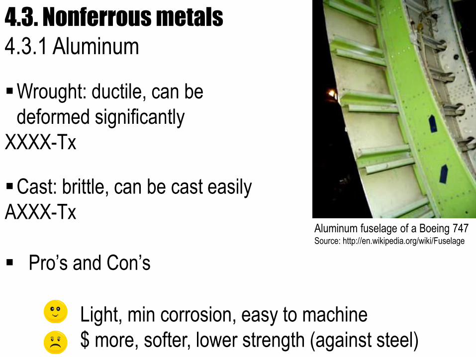
4.3. Nonferrous metals
4.3.1 Aluminum
Aluminum fuselage of a Boeing 747Source: http://en.wikipedia.org/wiki/Fuselage
Wrought: ductile, can be
deformed significantly
XXXX-Tx
Cast: brittle, can be cast easily
AXXX-Tx
Pro’s and Con’s
Light, min corrosion, easy to machine
$ more, softer, lower strength (against steel)
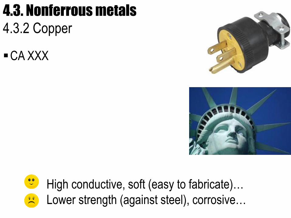
4.3. Nonferrous metals
4.3.2 Copper
CA XXX
High conductive, soft (easy to fabricate)…
Lower strength (against steel), corrosive…
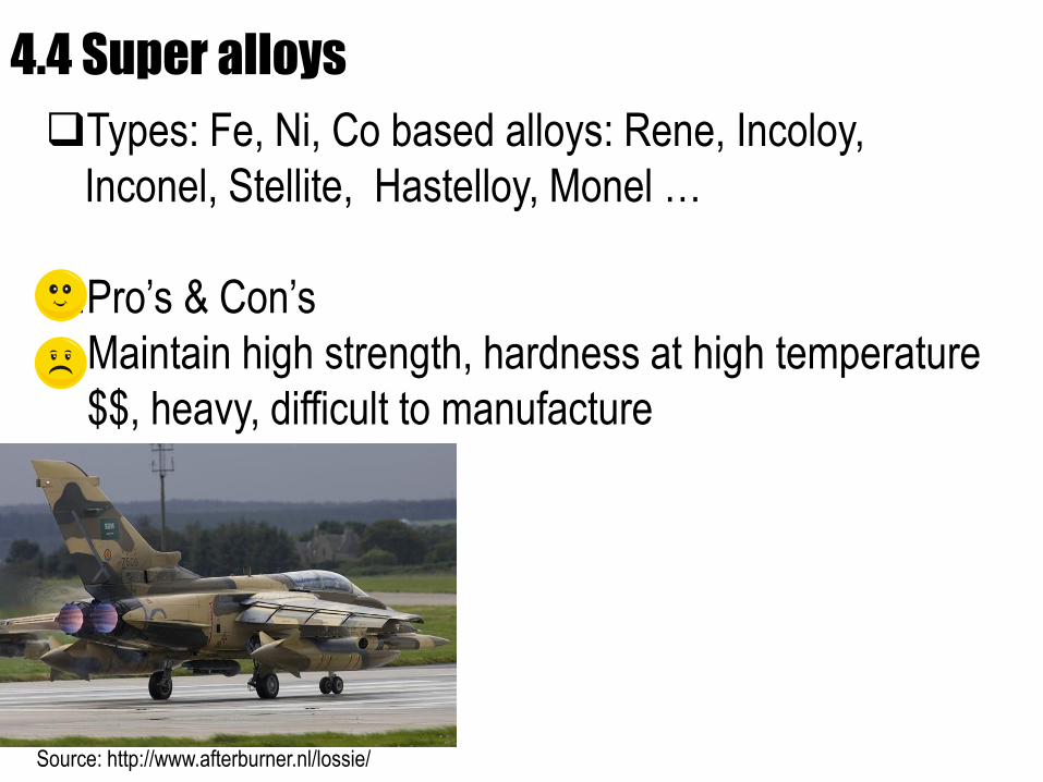
4.4 Super alloys
Source: http://www.afterburner.nl/lossie/
Types: Fe, Ni, Co based alloys: Rene, Incoloy,
Inconel, Stellite, Hastelloy, Monel …
Pro’s & Con’s
Maintain high strength, hardness at high temperature
$$, heavy, difficult to manufacture
5. Polymers Basic elements: C, H, O, N
Polymerization: combine carbons
and others to chain molecules.health.yahoo.net
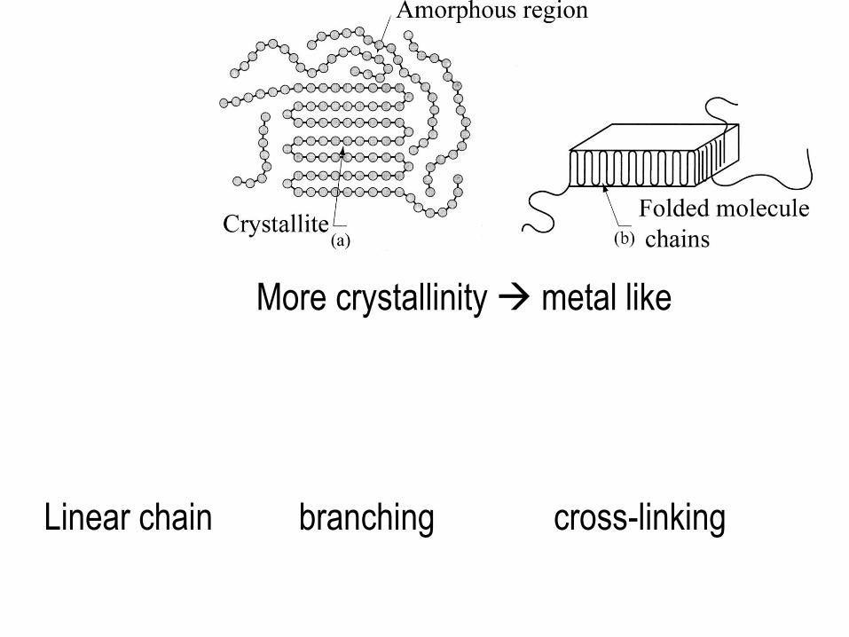
More crystallinity metal like
Linear chain branching cross-linking
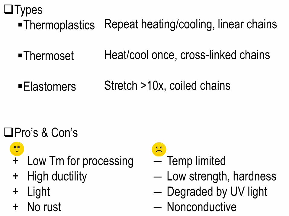
Types
Thermoplastics
Thermoset
Elastomers
Pro’s & Con’s
― Temp limited
― Low strength, hardness
― Degraded by UV light
― Nonconductive
+ Low Tm for processing
+ High ductility
+ Light
+ No rust
Repeat heating/cooling, linear chains
Heat/cool once, cross-linked chains
Stretch >10x, coiled chains
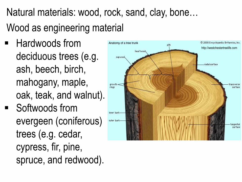
Natural materials: wood, rock, sand, clay, bone…
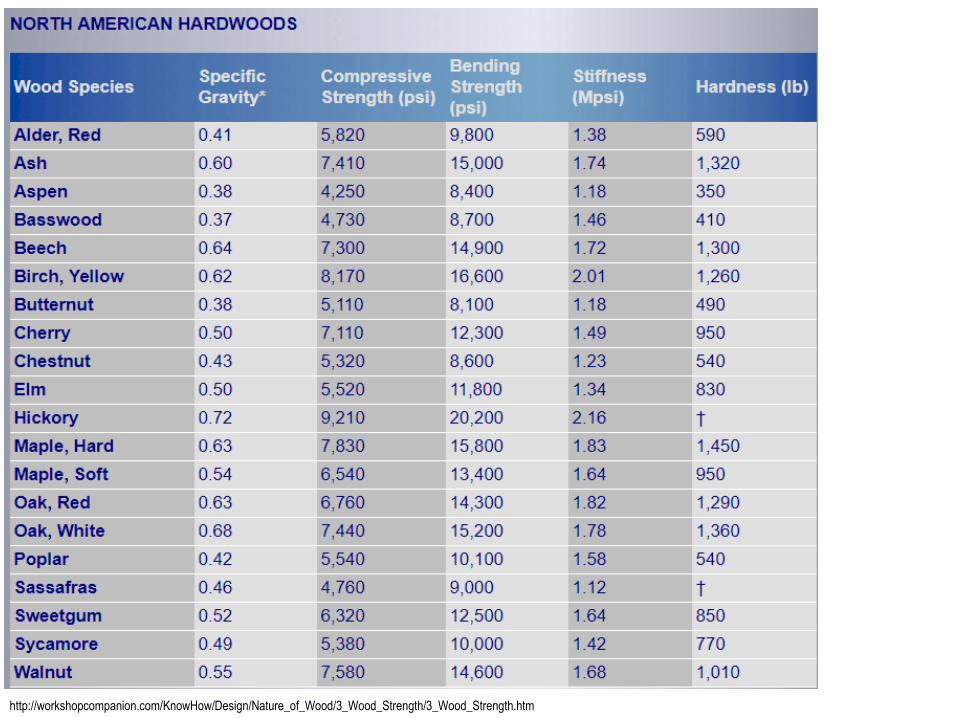
Wood as engineering material
Hardwoods from
deciduous trees (e.g.
ash, beech, birch,
mahogany, maple,
oak, teak, and walnut).
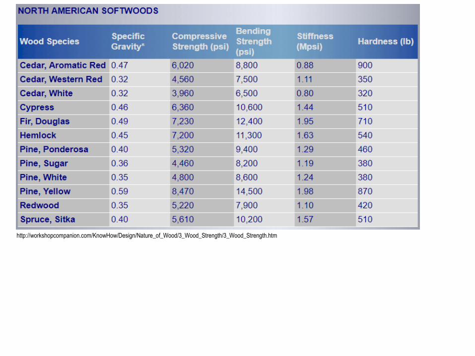
Softwoods from
evergeen (coniferous)
trees (e.g. cedar,
cypress, fir, pine,
spruce, and redwood).
http://westchestertreelife.com
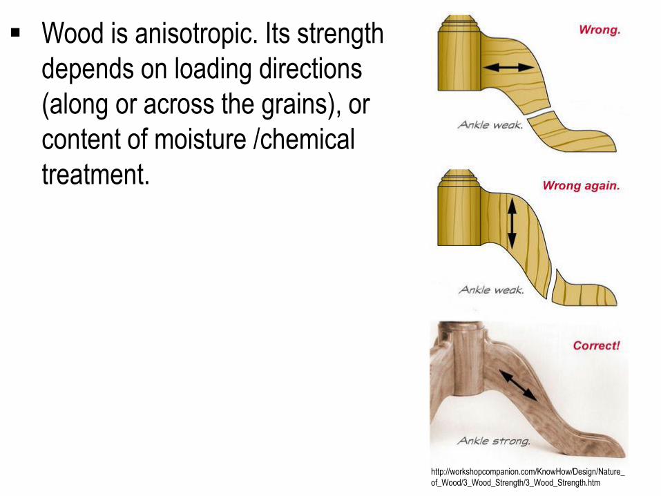
Wood is anisotropic. Its strength
depends on loading directions
(along or across the grains), or
content of moisture /chemical
treatment.
http://workshopcompanion.com/KnowHow/Design/Nature_
of_Wood/3_Wood_Strength/3_Wood_Strength.htm
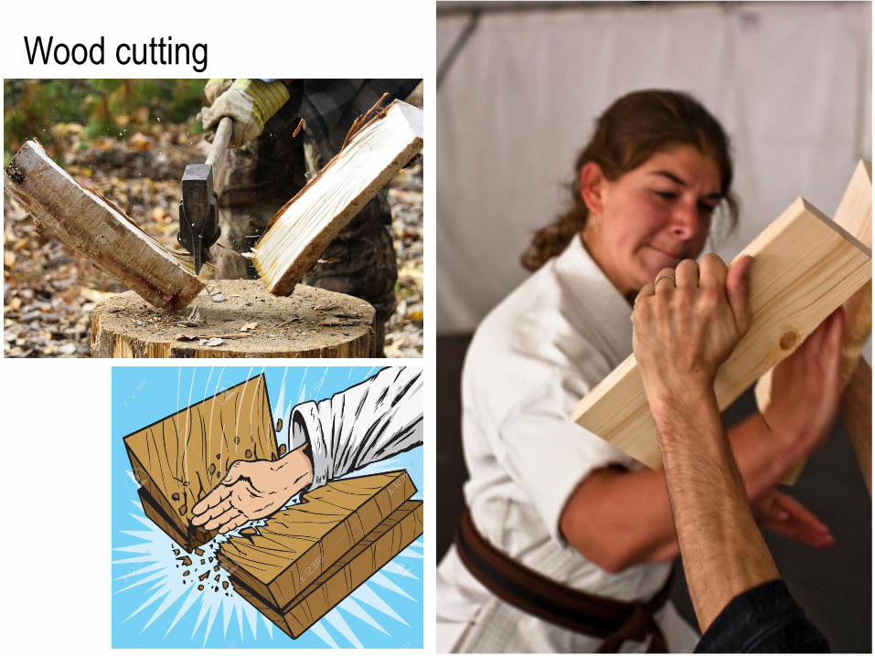
Wood cutting
http://workshopcompanion.com/KnowHow/Design/Nature_of_Wood/3_Wood_Strength/3_Wood_Strength.htm
http://workshopcompanion.com/KnowHow/Design/Nature_of_Wood/3_Wood_Strength/3_Wood_Strength.htm
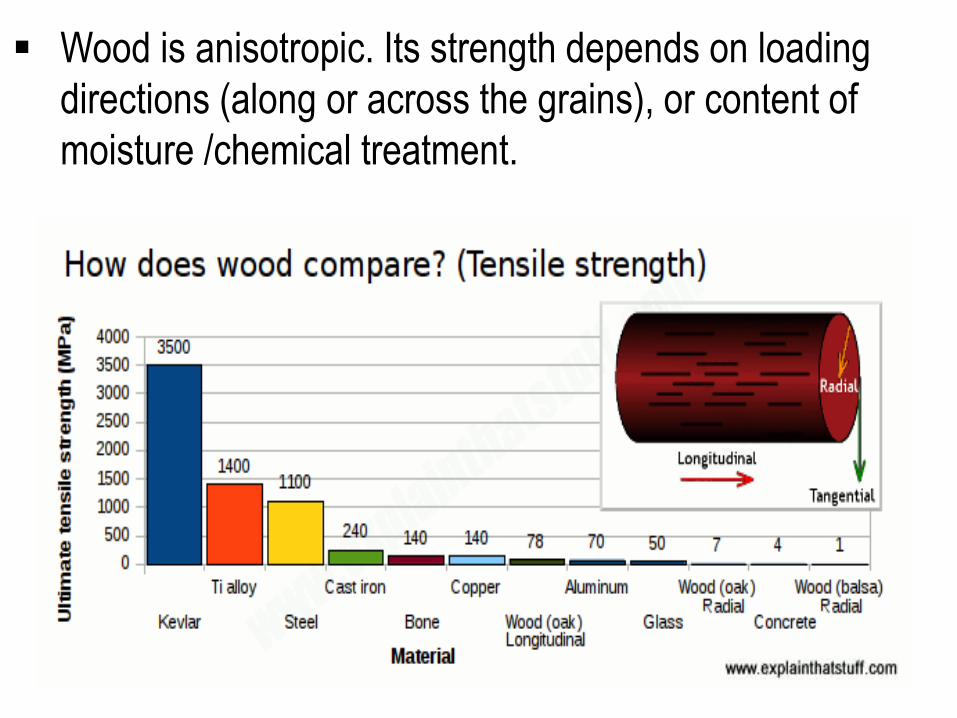
Wood is anisotropic. Its strength depends on loading
directions (along or across the grains), or content of
moisture /chemical treatment.
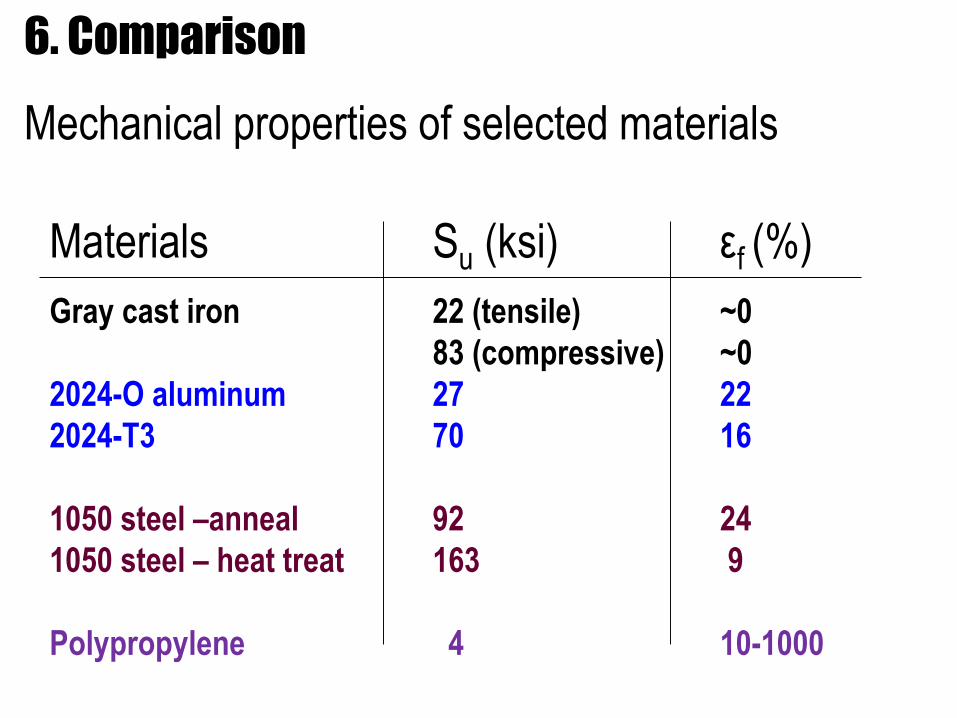
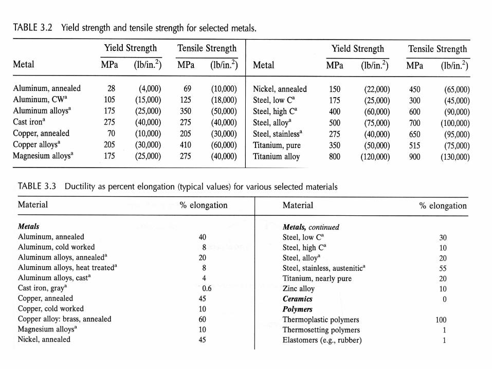
6. Comparison
Mechanical properties of selected materials
Materials Su (ksi) εf (%)
Gray cast iron 22 (tensile) ~0
83 (compressive) ~0
2024-O aluminum 27 22
2024-T3 70 16
1050 steel –anneal 92 24
1050 steel – heat treat 163 9
Polypropylene 4 10-1000
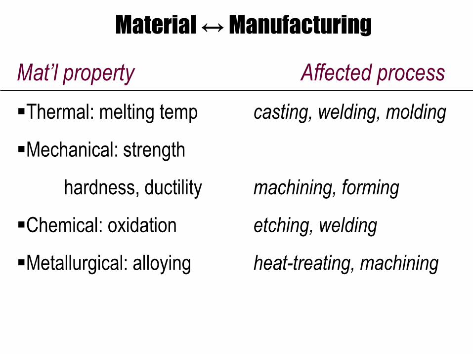
Material ↔ Manufacturing
Mat’l property Affected process
Thermal: melting temp casting, welding, molding
Mechanical: strength
hardness, ductility machining, forming
Chemical: oxidation etching, welding
Metallurgical: alloying heat-treating, machining
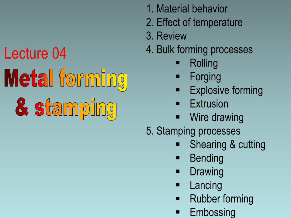
1. Material behavior
2. Effect of temperature
3. Review
4. Bulk forming processes
Rolling
Forging
Explosive forming
Extrusion
Wire drawing
5. Stamping processes
Shearing & cutting
Bending
Drawing
Lancing
Rubber forming
Embossing
Lecture 04
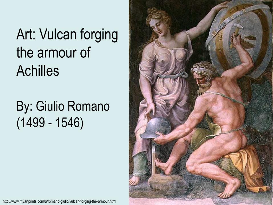
http://www.myartprints.com/a/romano-giulio/vulcan-forging-the-armour.html
Art: Vulcan forging
the armour of
Achilles
By: Giulio Romano
(1499 - 1546)
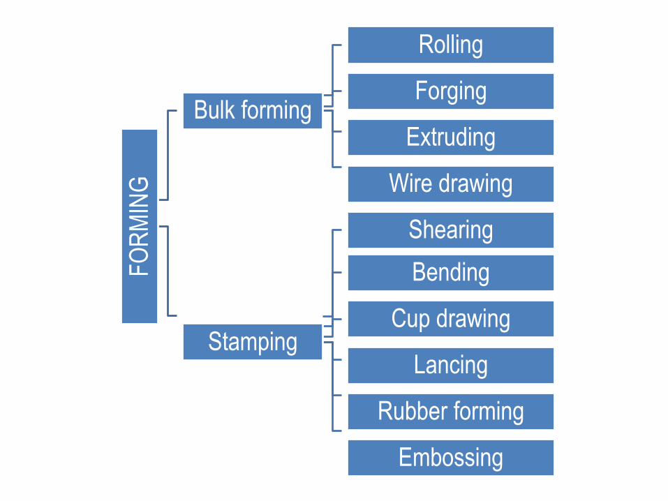
FO
RM
ING
Bulk forming
Rolling
Forging
Extruding
Wire drawing
Stamping
Shearing
Bending
Cup drawing
Lancing
Rubber forming
Embossing

1. Material behavior
2. Effect of temperature
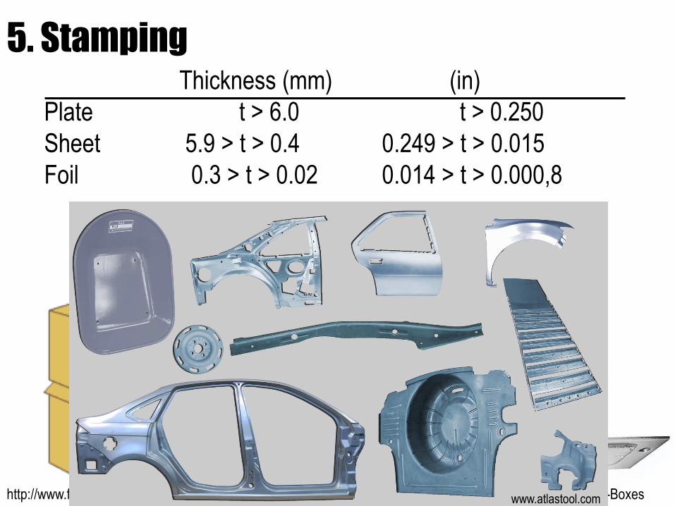
5. StampingThickness (mm) (in)
Plate t > 6.0 t > 0.250
Sheet 5.9 > t > 0.4 0.249 > t > 0.015
Foil 0.3 > t > 0.02 0.014 > t > 0.000,8
http://www.fennstrading.com/ http://www.garvinindustries.com/Electrical-Junction-Boxeswww.atlastool.com
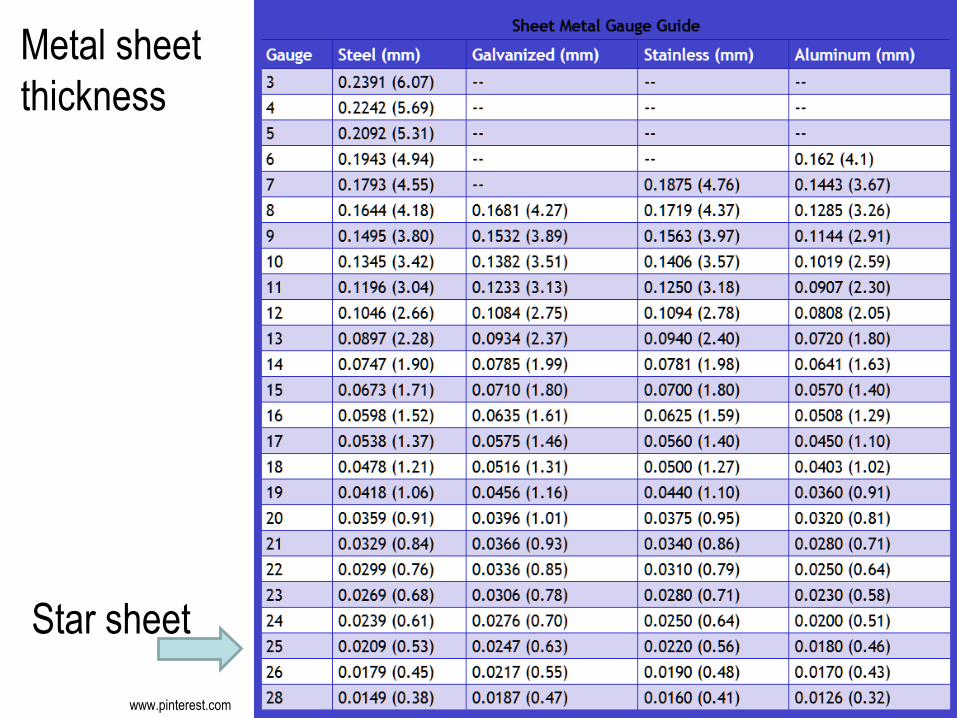
Metal sheet
thickness
www.pinterest.com
Star sheet
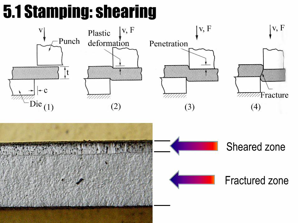
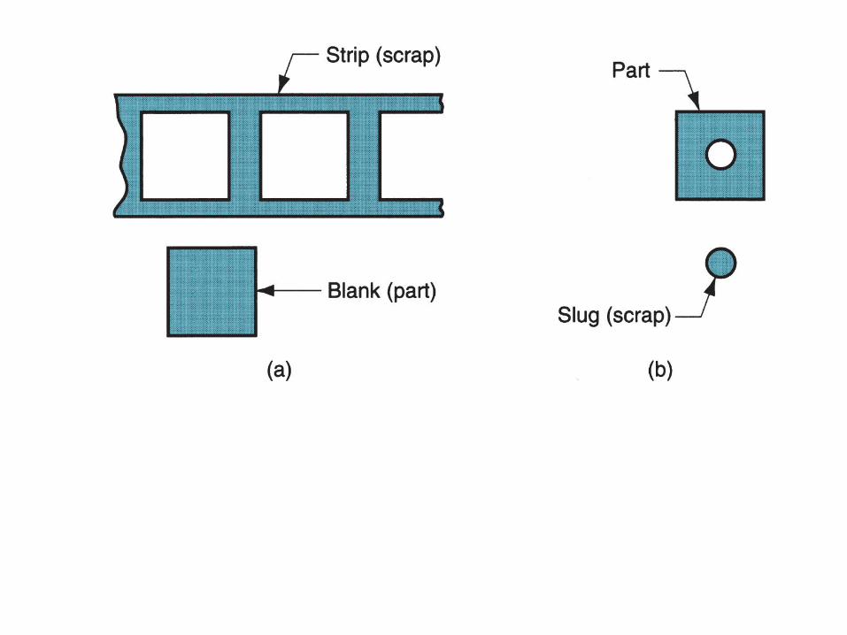
5.1 Stamping: shearing
Sheared zone
Fractured zone
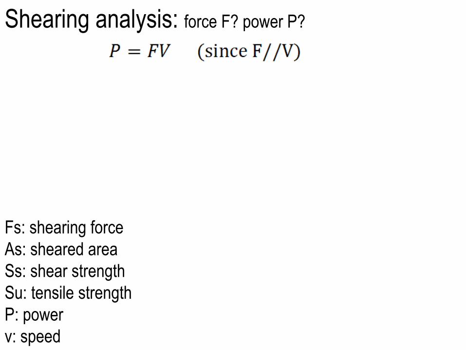
Shearing analysis: force F? power P?
Fs: shearing force
As: sheared area
Ss: shear strength
Su: tensile strength
P: power
v: speed
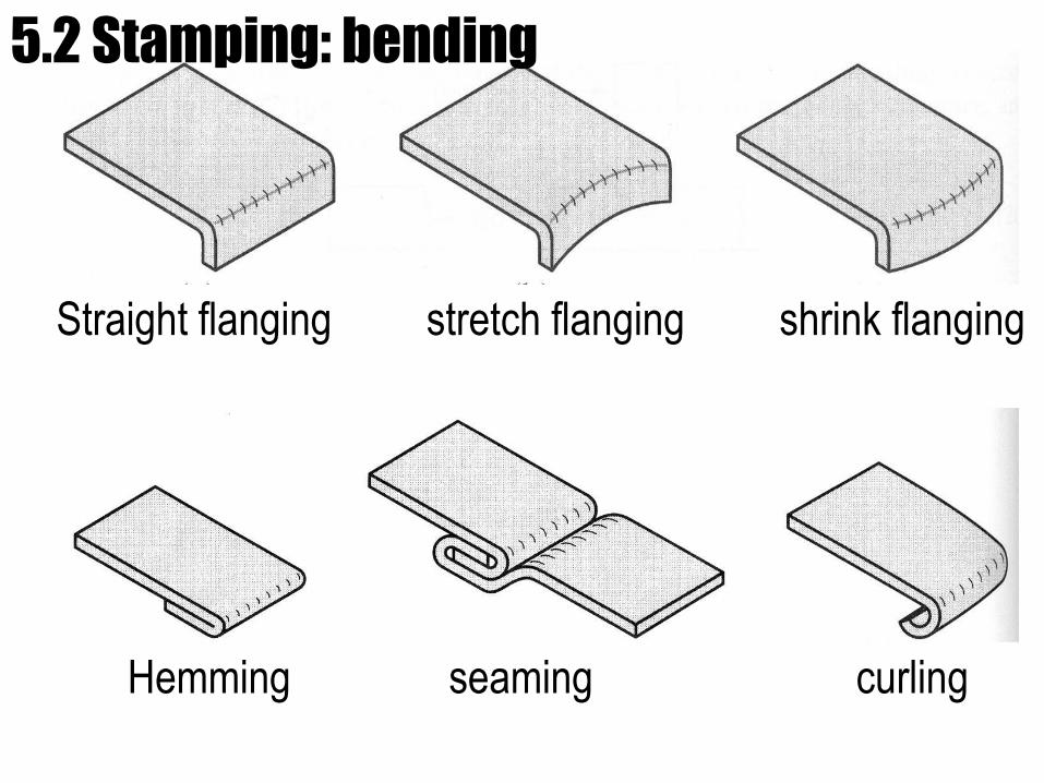
Straight flanging stretch flanging shrink flanging
Hemming seaming curling
5.2 Stamping: bending
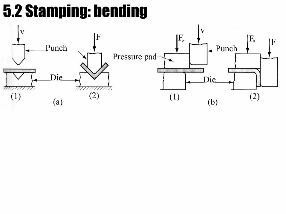
5.2 Stamping: bending
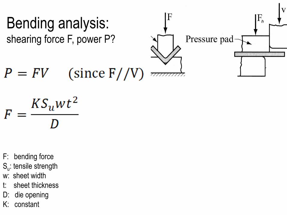
Bending analysis: shearing force F, power P?
F: bending force
Su: tensile strength
w: sheet width
t: sheet thickness
D: die opening
K: constant
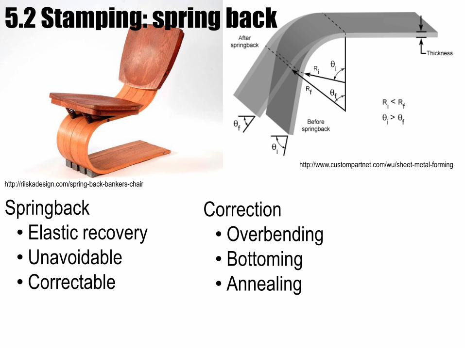
http://riiskadesign.com/spring-back-bankers-chair
Springback
• Elastic recovery
• Unavoidable
• Correctable
http://www.custompartnet.com/wu/sheet-metal-forming
Correction
• Overbending
• Bottoming
• Annealing
5.2 Stamping: spring back
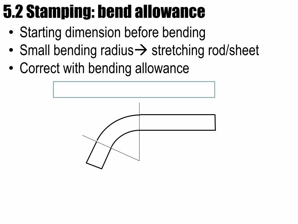
• Starting dimension before bending
• Small bending radius stretching rod/sheet
• Correct with bending allowance
5.2 Stamping: bend allowance
http://technote-ashok.blogspot.com/2011_01_01_archive.html
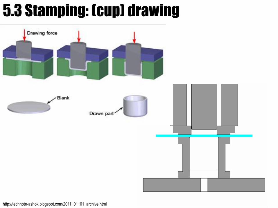
5.3 Stamping: (cup) drawing
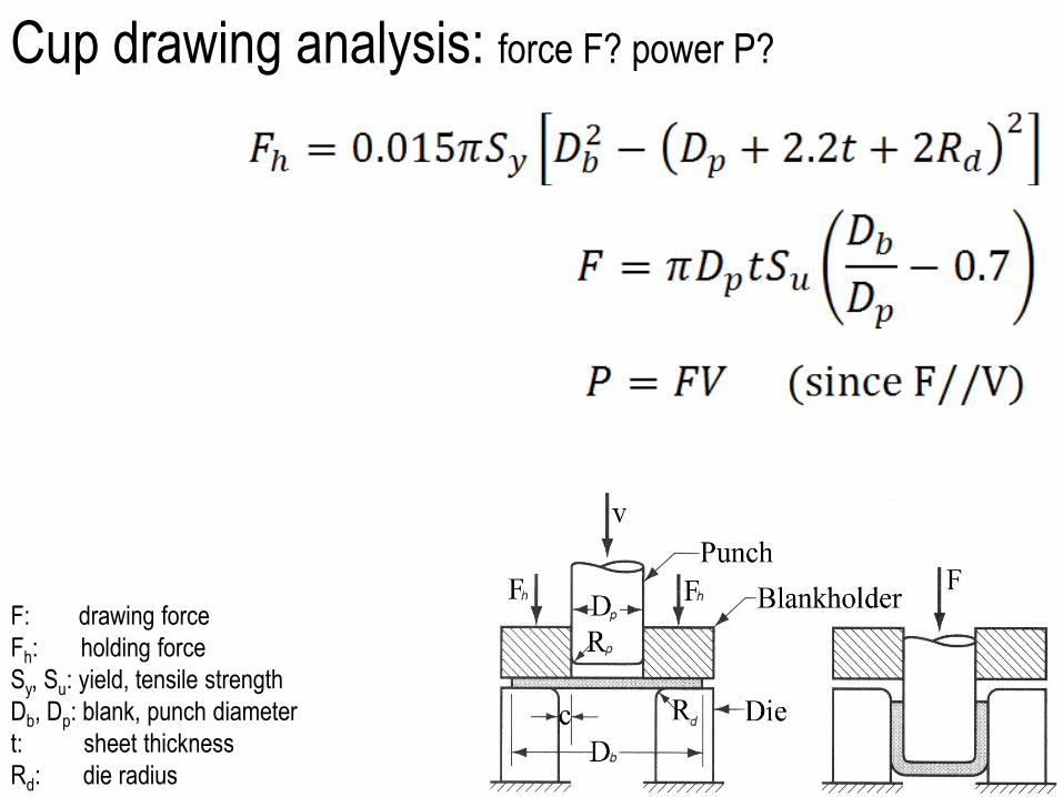
F: drawing force
Fh: holding force
Sy, Su: yield, tensile strength
Db, Dp: blank, punch diameter
t: sheet thickness
Rd: die radius
Cup drawing analysis: force F? power P?
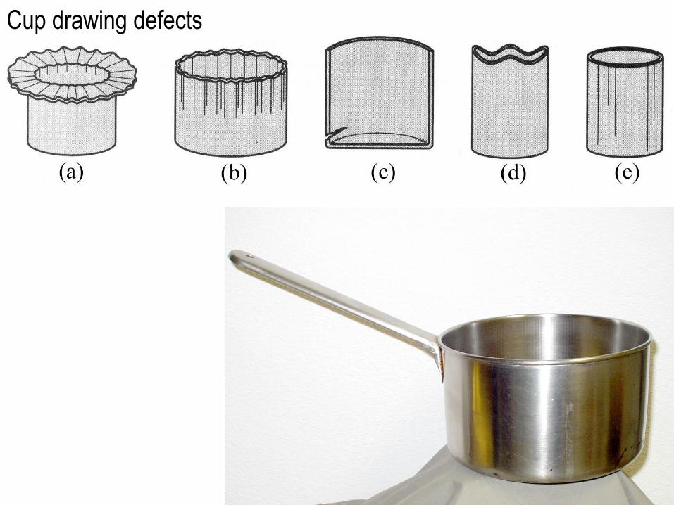
Cup drawing defects
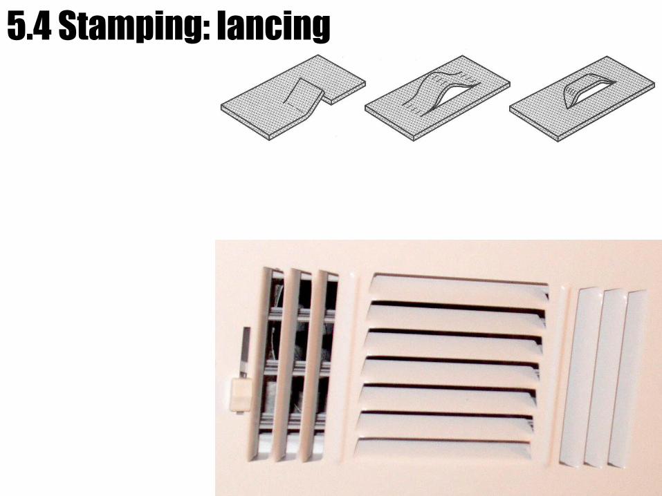
5.4 Stamping: lancing
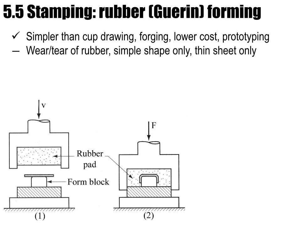
5.5 Stamping: rubber (Guerin) forming
Simpler than cup drawing, forging, lower cost, prototyping
― Wear/tear of rubber, simple shape only, thin sheet only
www.quia.com
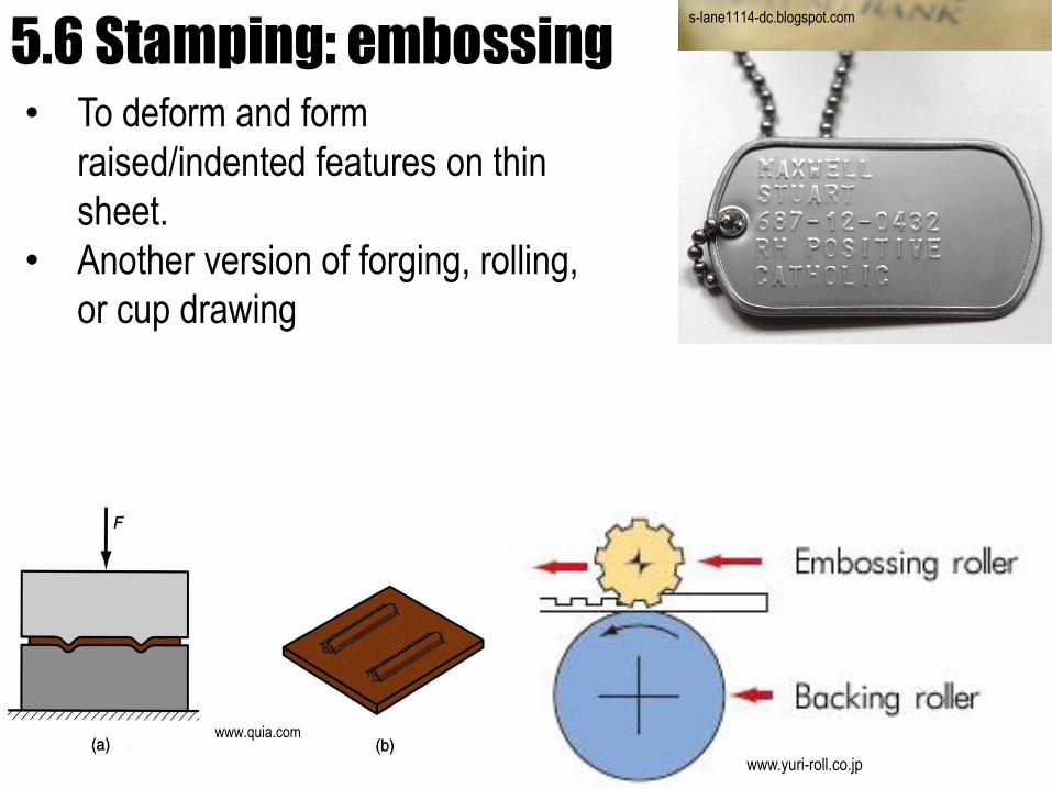
5.6 Stamping: embossing• To deform and form
raised/indented features on thin
sheet.
• Another version of forging, rolling,
or cup drawing
s-lane1114-dc.blogspot.com
www.yuri-roll.co.jp
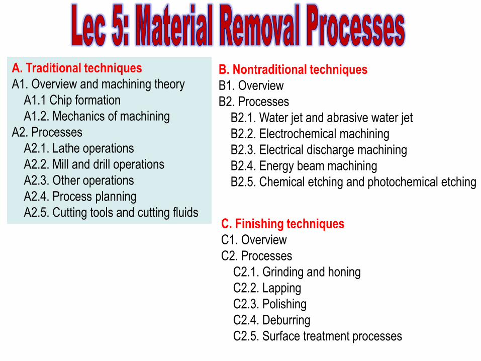
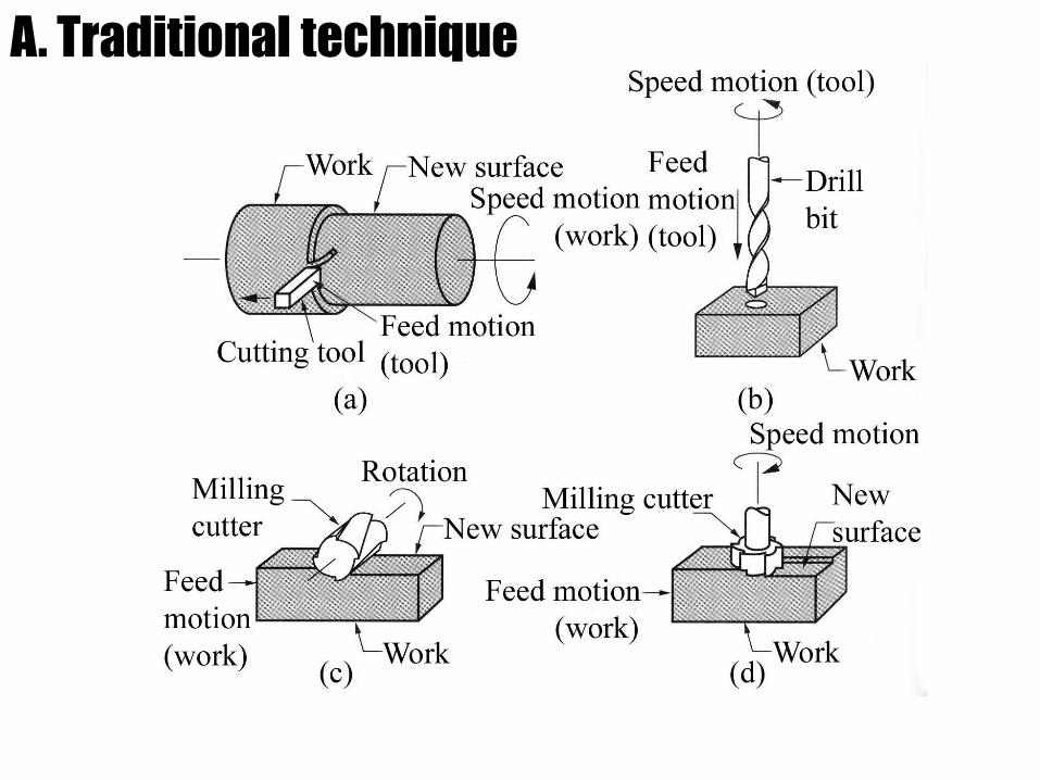
A. Traditional techniques
A1. Overview and machining theory
A1.1 Chip formation
A1.2. Mechanics of machining
A2. Processes
A2.1. Lathe operations
A2.2. Mill and drill operations
A2.3. Other operations
A2.4. Process planning
A2.5. Cutting tools and cutting fluids
B. Nontraditional techniques
B1. Overview
B2. Processes
B2.1. Water jet and abrasive water jet
B2.2. Electrochemical machining
B2.3. Electrical discharge machining
B2.4. Energy beam machining
B2.5. Chemical etching and photochemical etching
C. Finishing techniques
C1. Overview
C2. Processes
C2.1. Grinding and honing
C2.2. Lapping
C2.3. Polishing
C2.4. Deburring
C2.5. Surface treatment processes
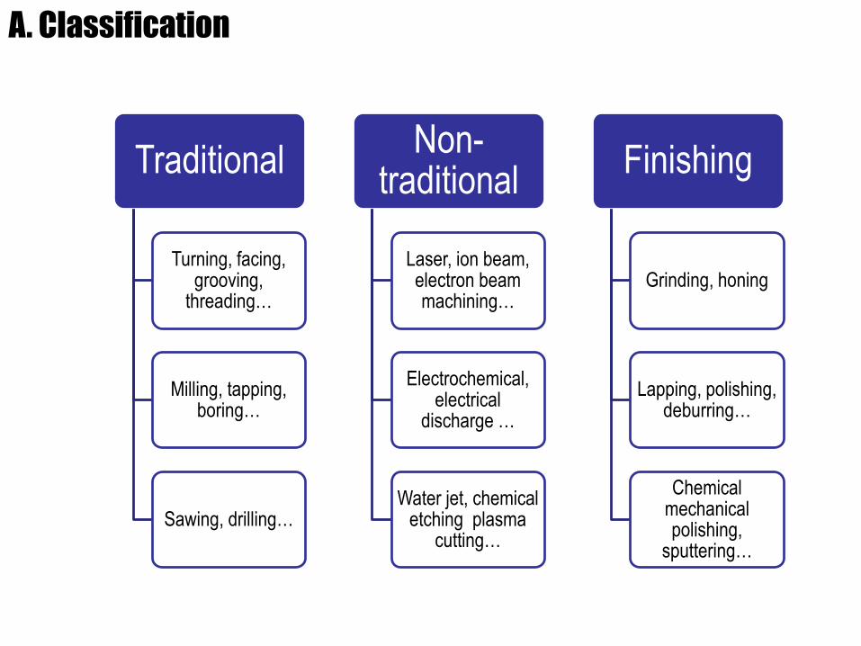
A. Classification
Traditional
Turning, facing, grooving,
threading…
Milling, tapping, boring…
Sawing, drilling…
Non-traditional
Laser, ion beam, electron beam machining…
Electrochemical, electrical
discharge …
Water jet, chemical etching plasma
cutting…
Finishing
Grinding, honing
Lapping, polishing, deburring…
Chemical mechanical polishing,
sputtering…
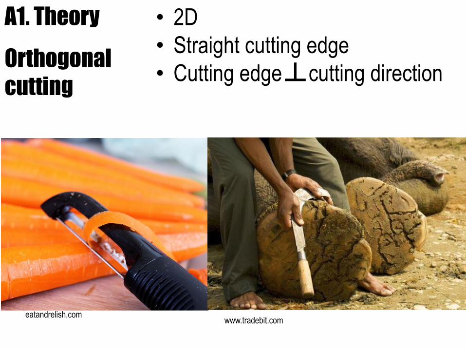
A1. Theory
Orthogonal
cutting
• 2D
• Straight cutting edge
• Cutting edge cutting direction
eatandrelish.comwww.tradebit.com
┴
A. Traditional technique
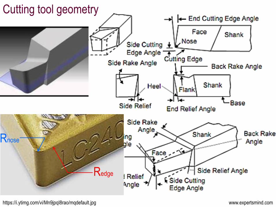
www.expertsmind.comhttps://i.ytimg.com/vi/Mn9jpqI8rao/mqdefault.jpg
Cutting tool geometry
Rnose
Redge
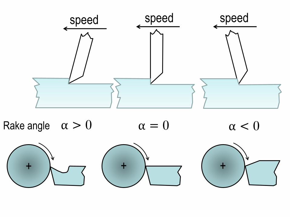
Rake angle
+ ++
α > 0 α = 0 α < 0
speed speed speed
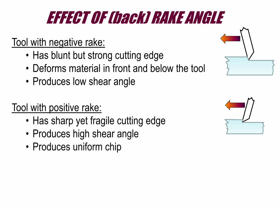
EFFECT OF (back) RAKE ANGLE
Tool with negative rake:
• Has blunt but strong cutting edge
• Deforms material in front and below the tool
• Produces low shear angle
Tool with positive rake:
• Has sharp yet fragile cutting edge
• Produces high shear angle
• Produces uniform chip
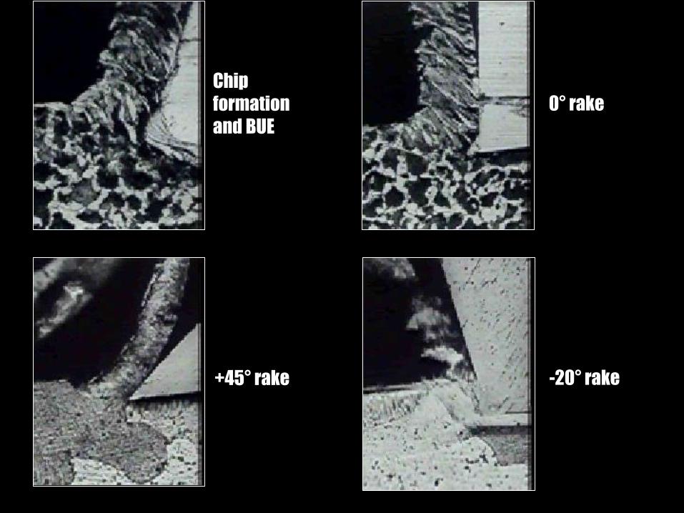
-20° rake
0° rake
+45° rake
Chip
formation
and BUE
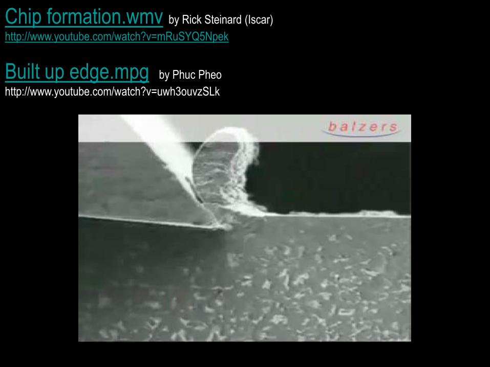
Built up edge.mpg, by Phuc Pheo
http://www.youtube.com/watch?v=uwh3ouvzSLk
Chip formation.wmv, by Rick Steinard (Iscar)
http://www.youtube.com/watch?v=mRuSYQ5Npek
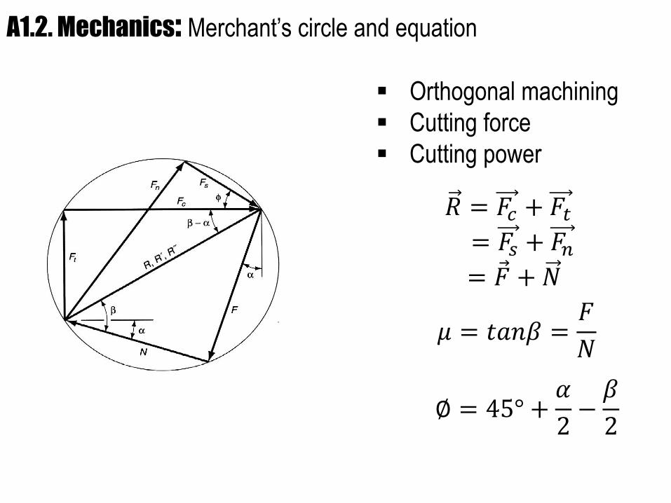
A1.2. Mechanics: Merchant’s circle and equation
Orthogonal machining
Cutting force
Cutting power
𝑅 = 𝐹𝑐 + 𝐹𝑡= 𝐹𝑠 + 𝐹𝑛= Ԧ𝐹 + 𝑁
𝜇 = 𝑡𝑎𝑛𝛽 =𝐹
𝑁
∅ = 45° +𝛼
2−𝛽
2
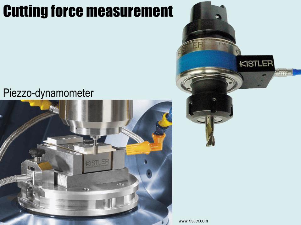
Cutting force measurement
Piezzo-dynamometer
www.kistler.com
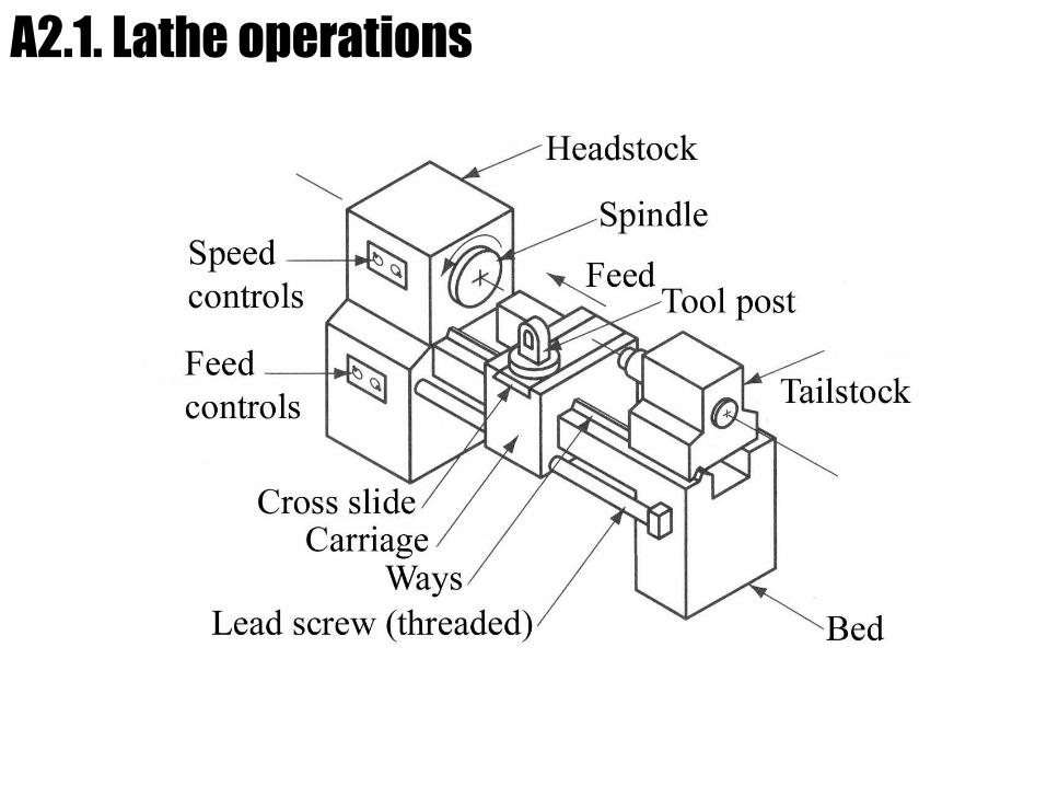
A2.1. Lathe operations
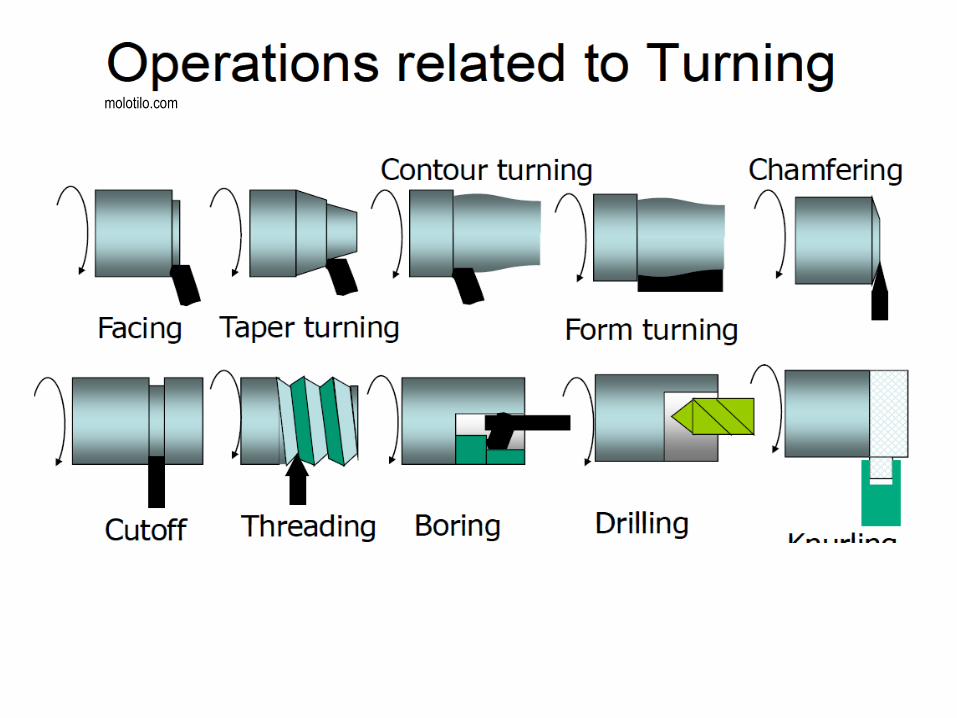
molotilo.com
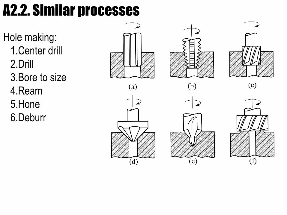
Hole making:
1.Center drill
2.Drill
3.Bore to size
4.Ream
5.Hone
6.Deburr
A2.2. Similar processes
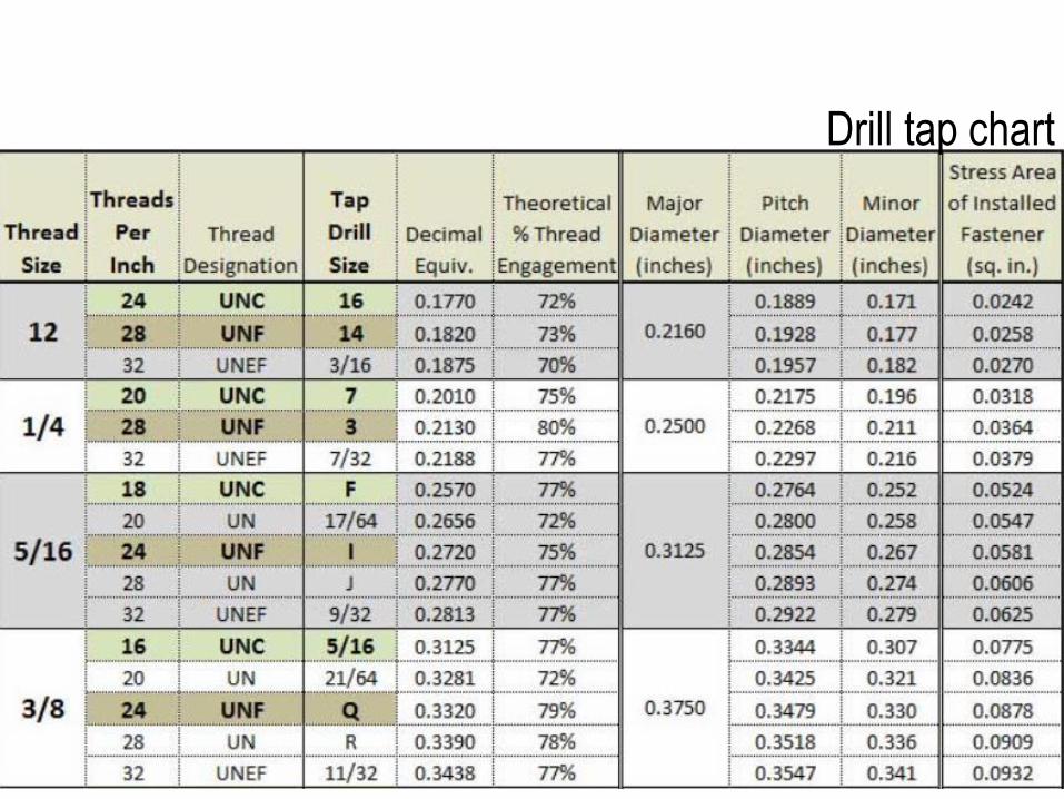
Drill tap chart
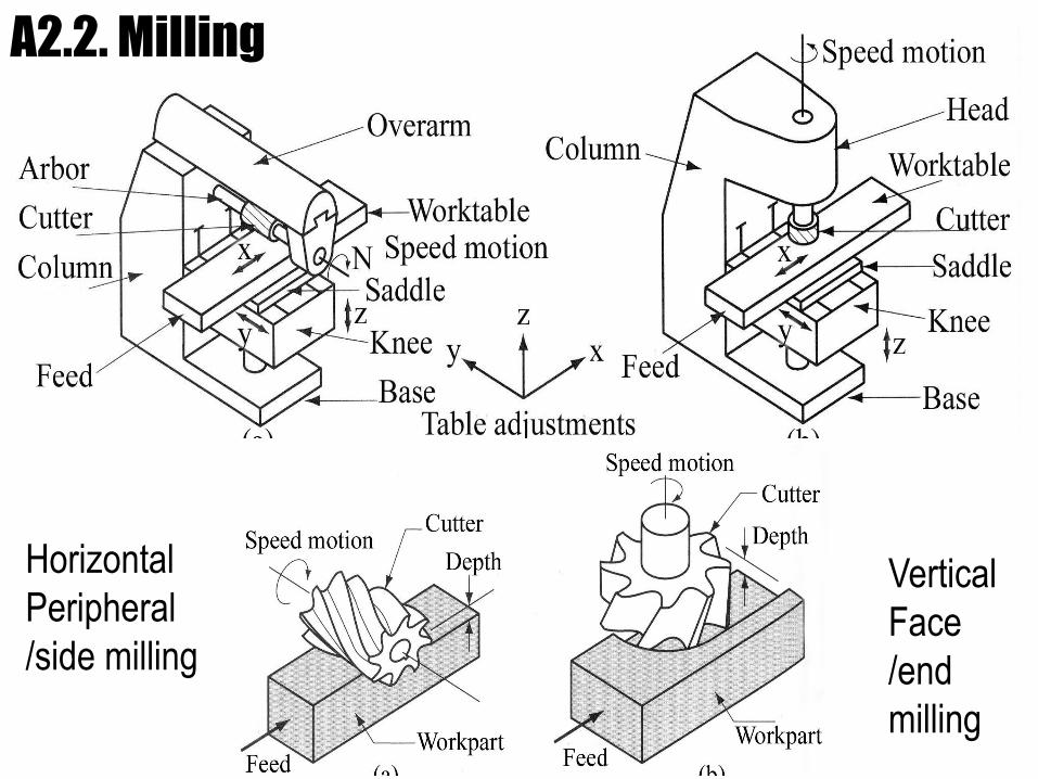
A2.2. Milling
Horizontal
Peripheral
/side milling
Vertical
Face
/end
milling
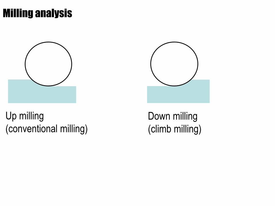
Milling analysis
Up milling
(conventional milling)
Down milling
(climb milling)
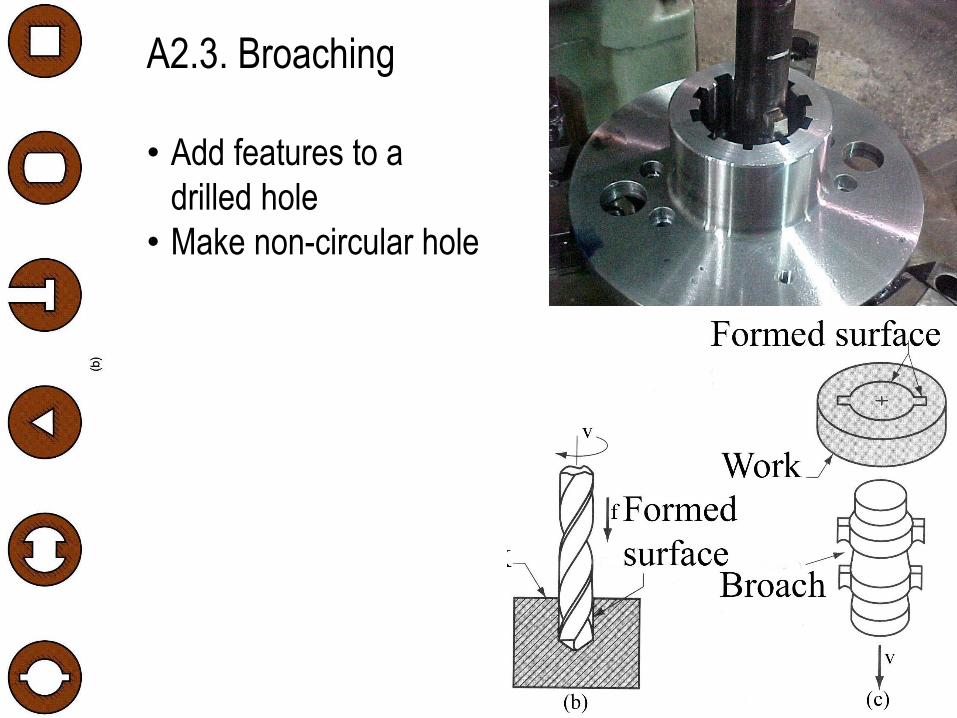
A2.3. Broaching
• Add features to a
drilled hole
• Make non-circular hole
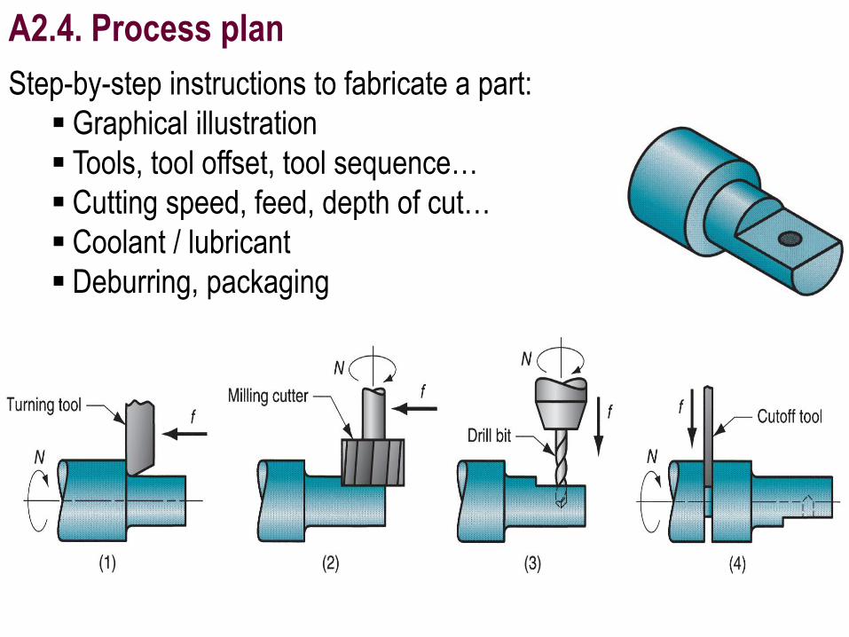
A2.4. Process plan
Step-by-step instructions to fabricate a part:
Graphical illustration
Tools, tool offset, tool sequence…
Cutting speed, feed, depth of cut…
Coolant / lubricant
Deburring, packaging
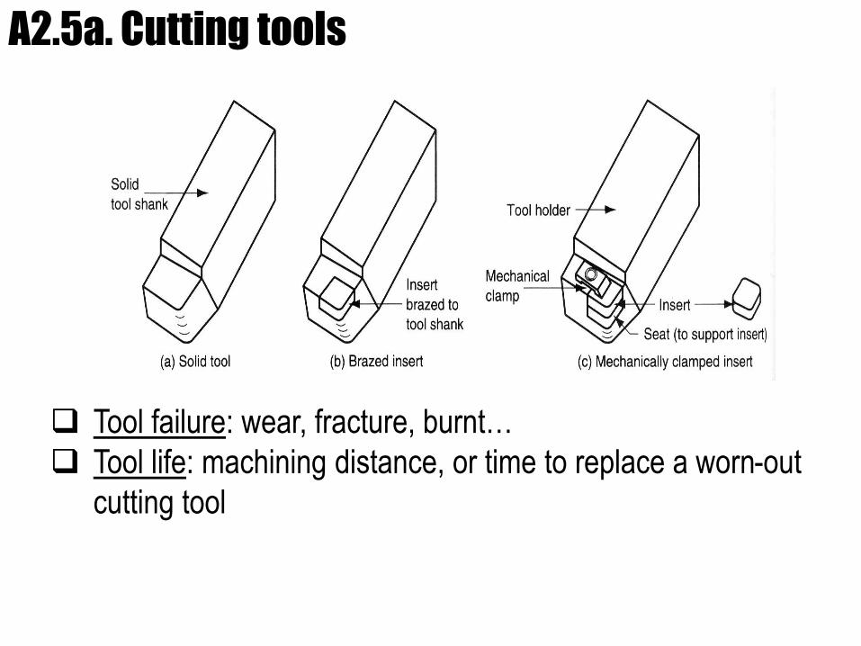
A2.5a. Cutting tools
Tool failure: wear, fracture, burnt…
Tool life: machining distance, or time to replace a worn-out
cutting tool
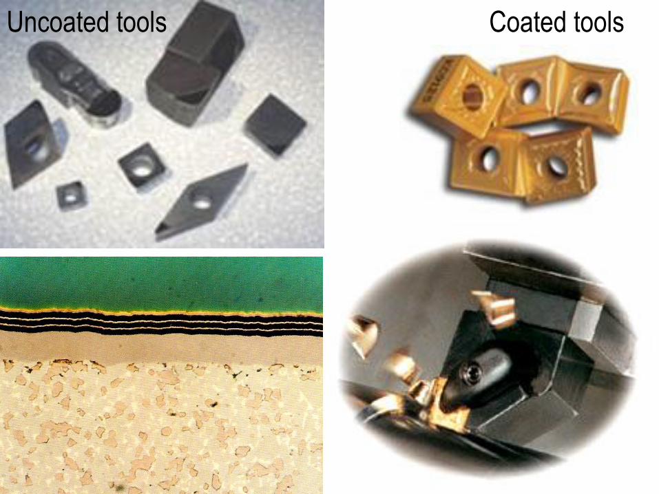
Uncoated tools Coated tools
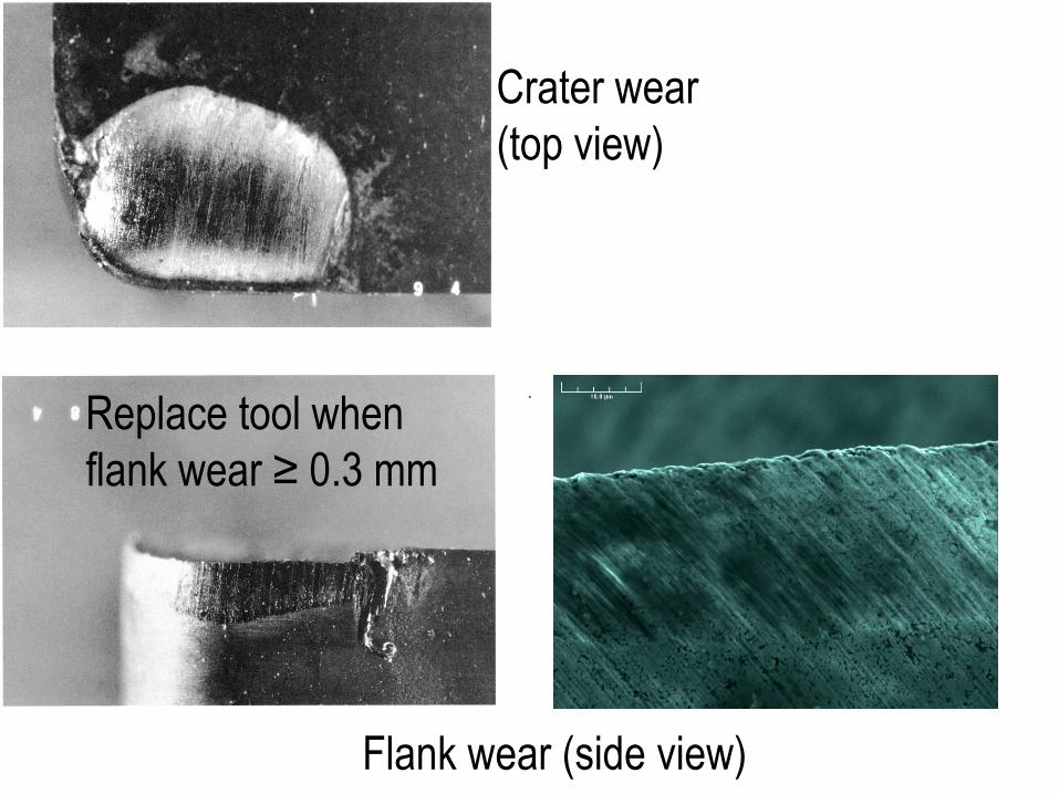
Crater wear
(top view)
Flank wear (side view)
Replace tool when
flank wear ≥ 0.3 mm
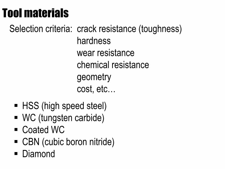
Tool materials
Selection criteria: crack resistance (toughness)
hardness
wear resistance
chemical resistance
geometry
cost, etc…
HSS (high speed steel)
WC (tungsten carbide)
Coated WC
CBN (cubic boron nitride)
Diamond
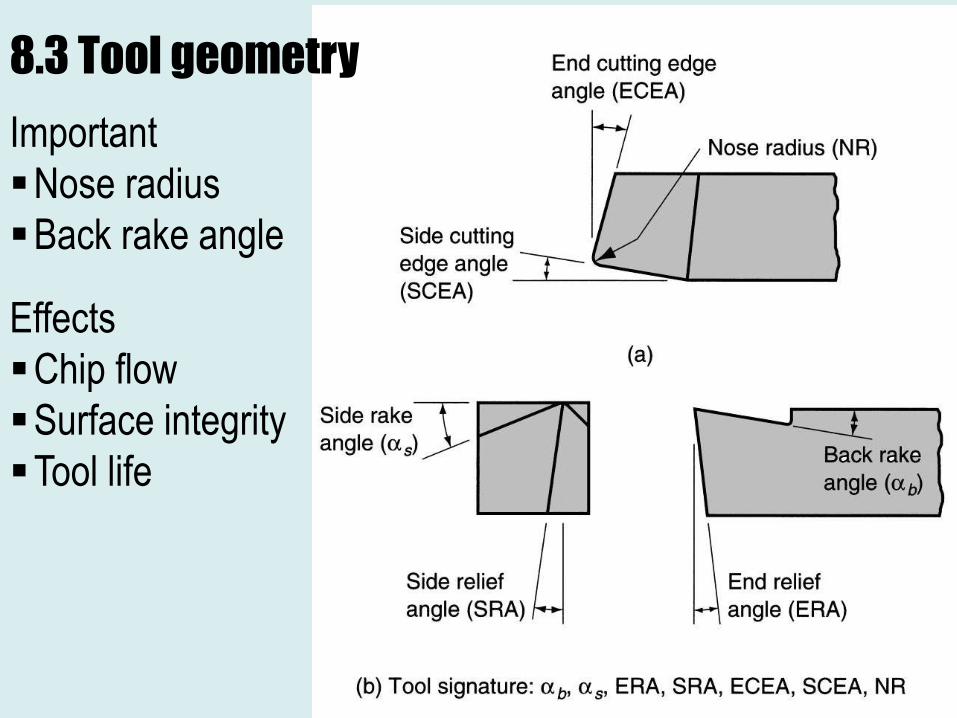
8.3 Tool geometry
Important
Nose radius
Back rake angle
Effects
Chip flow
Surface integrity
Tool life
30
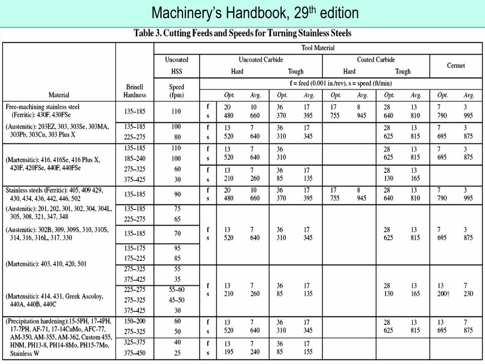
Machinery’s Handbook, 29th edition
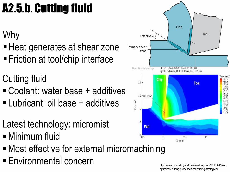
A2.5.b. Cutting fluid
Why
Heat generates at shear zone
Friction at tool/chip interface
Cutting fluid
Coolant: water base + additives
Lubricant: oil base + additives
Latest technology: micromist
Minimum fluid
Most effective for external micromachining
Environmental concern http://www.fabricatingandmetalworking.com/2013/04/fea-
optimizes-cutting-processes-machining-strategies/
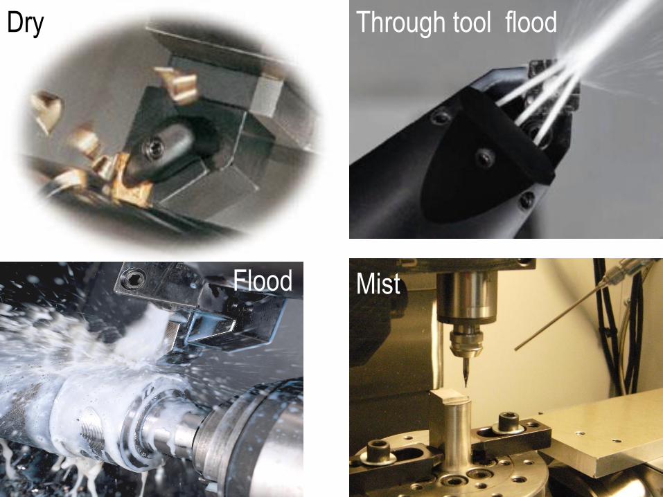
Flood
Dry Through tool flood
Mist
Related Documents