energies Article Review of Design Elements within Power Infrastructure Cyber–Physical Test Beds as Threat Analysis Environments Bjorn Vaagensmith 1, * , Vivek Kumar Singh 1 , Robert Ivans 1 , Daniel L. Marino 2 , Chathurika S. Wickramasinghe 2 , Jacob Lehmer 1 , Tyler Phillips 1 , Craig Rieger 1 and Milos Manic 2 Citation: Vaagensmith, B.; Kumar, V.; Ivans, R.; Marino, D.L.; Wickramasinghe, C.S.; Lehmer, J.; Phillips, T.; Rieger, C.; Manic, M. Review of Design Elements within Power Infrastructure Cyber–Physical Test Beds as Threat Analysis Environments. Energies 2021, 14, 1409. https://doi.org/10.3390/ en14051409 Academic Editor: Edmund Widl Received: 6 January 2021 Accepted: 15 February 2021 Published: 4 March 2021 Publisher’s Note: MDPI stays neutral with regard to jurisdictional claims in published maps and institutional affil- iations. Copyright: © 2021 by the authors. Licensee MDPI, Basel, Switzerland. This article is an open access article distributed under the terms and conditions of the Creative Commons Attribution (CC BY) license (https:// creativecommons.org/licenses/by/ 4.0/). 1 Idaho National Laboratory, Idaho Falls, ID 83415, USA; [email protected] (V.K.S.); [email protected] (R.I.); [email protected] (J.L.); [email protected] (T.P.); [email protected] (C.R.) 2 College of Engineering, Virginia Commonwealth University, 601 West Main Street, Richmond, VA 23284, USA; [email protected] (D.L.M.); [email protected] (C.S.W.); [email protected] (M.M.) * Correspondence: [email protected]; Tel.: +1-208-526-4008 Abstract: Cyber–physical systems (CPSs) are an integral part of modern society; thus, enhancing these systems’ reliability and resilience is paramount. Cyber–physical testbeds (CPTs) are a safe way to test and explore the interplay between the cyber and physical domains and to cost-effectively enhance the reliability and resilience of CPSs. Here a review of CPT elements, broken down into physical components (simulators, emulators, and physical hardware), soft components (communi- cation protocols, network timing protocols), and user interfaces (visualization-dashboard design considerations) is presented. Various methods used to validate CPS performance are reviewed and evaluated for potential applications in CPT performance validation. Last, initial simulated results for a CPT design, based on the IEEE 33 bus system, are presented, along with a brief discussion on how model-based testing and fault–injection-based testing (using scaling and ramp-type attacks) may be used to help validate CPT performance. Keywords: cyber–physical system; smart grid; communication protocols; network timing; data visualization; ramp attack; scaling attack; cyber–physical testbed metrics 1. Introduction Electricity, used as a medium for either data or power transfer, plays an essential roll in maintaining and advancing the quality of life for modern society. As its penetration in day-to-day life becomes ubiquitous, our dependency on electricity’s presence and vulnerability in its absence increases. Therefore, ensuring the reliability and resilience of the electric power grid is essential. Natural disasters are the most common threat to the modern-day electric grid, accounting for 62% and 90% of major power outages in 2016 and 2017, respectively, according to the Department of Energy, Office of Electricity (DOE-OE) Electric Disturbance Events OE-417 forms [1]. Cyberattacks also have the potential to cause widespread blackouts [2] and damage to power transformers (via remote control of breakers) [3] or generators [4,5]. Additionally, cyberattacks may be deployed en masse (with frequencies as high as 10,000 attacks per minute [6]) alongside a natural disaster. To address these challenges and ensure resilient and reliable power-grid operation, the interplay between the digital and physical realm must be understood and properly guarded. The need for reliability negates the possibility of direct experiment on critical in- frastructure, and the cost to produce a direct replica is often too high. To overcome this challenge, cyber–physical test beds (CPTs), with a primary aim to explore how the physical and digital world impact each other, are needed. Varying degrees of hardware-in-the-loop (HIL) connected with simulations or emulations are most-often employed as a cost-effective means to probe the cyber–physical nature of critical systems [7]. These test beds must strike the appropriate balance among what is simulated, emulated, and physically manifested Energies 2021, 14, 1409. https://doi.org/10.3390/en14051409 https://www.mdpi.com/journal/energies

Welcome message from author
This document is posted to help you gain knowledge. Please leave a comment to let me know what you think about it! Share it to your friends and learn new things together.
Transcript
energies
Article
Review of Design Elements within Power InfrastructureCyber–Physical Test Beds as Threat Analysis Environments
Bjorn Vaagensmith 1,* , Vivek Kumar Singh 1 , Robert Ivans 1 , Daniel L. Marino 2 ,Chathurika S. Wickramasinghe 2, Jacob Lehmer 1 , Tyler Phillips 1 , Craig Rieger 1 and Milos Manic 2
�����������������
Citation: Vaagensmith, B.; Kumar, V.;
Ivans, R.; Marino, D.L.;
Wickramasinghe, C.S.; Lehmer, J.;
Phillips, T.; Rieger, C.; Manic, M.
Review of Design Elements within
Power Infrastructure Cyber–Physical
Test Beds as Threat Analysis
Environments. Energies 2021, 14,
1409. https://doi.org/10.3390/
en14051409
Academic Editor: Edmund Widl
Received: 6 January 2021
Accepted: 15 February 2021
Published: 4 March 2021
Publisher’s Note: MDPI stays neutral
with regard to jurisdictional claims in
published maps and institutional affil-
iations.
Copyright: © 2021 by the authors.
Licensee MDPI, Basel, Switzerland.
This article is an open access article
distributed under the terms and
conditions of the Creative Commons
Attribution (CC BY) license (https://
creativecommons.org/licenses/by/
4.0/).
1 Idaho National Laboratory, Idaho Falls, ID 83415, USA; [email protected] (V.K.S.);[email protected] (R.I.); [email protected] (J.L.); [email protected] (T.P.);[email protected] (C.R.)
2 College of Engineering, Virginia Commonwealth University, 601 West Main Street, Richmond, VA 23284, USA;[email protected] (D.L.M.); [email protected] (C.S.W.); [email protected] (M.M.)
* Correspondence: [email protected]; Tel.: +1-208-526-4008
Abstract: Cyber–physical systems (CPSs) are an integral part of modern society; thus, enhancingthese systems’ reliability and resilience is paramount. Cyber–physical testbeds (CPTs) are a safe wayto test and explore the interplay between the cyber and physical domains and to cost-effectivelyenhance the reliability and resilience of CPSs. Here a review of CPT elements, broken down intophysical components (simulators, emulators, and physical hardware), soft components (communi-cation protocols, network timing protocols), and user interfaces (visualization-dashboard designconsiderations) is presented. Various methods used to validate CPS performance are reviewed andevaluated for potential applications in CPT performance validation. Last, initial simulated results fora CPT design, based on the IEEE 33 bus system, are presented, along with a brief discussion on howmodel-based testing and fault–injection-based testing (using scaling and ramp-type attacks) may beused to help validate CPT performance.
Keywords: cyber–physical system; smart grid; communication protocols; network timing; datavisualization; ramp attack; scaling attack; cyber–physical testbed metrics
1. Introduction
Electricity, used as a medium for either data or power transfer, plays an essential rollin maintaining and advancing the quality of life for modern society. As its penetrationin day-to-day life becomes ubiquitous, our dependency on electricity’s presence andvulnerability in its absence increases. Therefore, ensuring the reliability and resilience ofthe electric power grid is essential. Natural disasters are the most common threat to themodern-day electric grid, accounting for 62% and 90% of major power outages in 2016 and2017, respectively, according to the Department of Energy, Office of Electricity (DOE-OE)Electric Disturbance Events OE-417 forms [1]. Cyberattacks also have the potential tocause widespread blackouts [2] and damage to power transformers (via remote control ofbreakers) [3] or generators [4,5]. Additionally, cyberattacks may be deployed en masse (withfrequencies as high as 10,000 attacks per minute [6]) alongside a natural disaster. To addressthese challenges and ensure resilient and reliable power-grid operation, the interplaybetween the digital and physical realm must be understood and properly guarded.
The need for reliability negates the possibility of direct experiment on critical in-frastructure, and the cost to produce a direct replica is often too high. To overcome thischallenge, cyber–physical test beds (CPTs), with a primary aim to explore how the physicaland digital world impact each other, are needed. Varying degrees of hardware-in-the-loop(HIL) connected with simulations or emulations are most-often employed as a cost-effectivemeans to probe the cyber–physical nature of critical systems [7]. These test beds must strikethe appropriate balance among what is simulated, emulated, and physically manifested
Energies 2021, 14, 1409. https://doi.org/10.3390/en14051409 https://www.mdpi.com/journal/energies
Energies 2021, 14, 1409 2 of 24
as HIL while maintaining the flexibility to cost-effectively study the resilience posture ofmany types of system typologies and configurations.
Many highly varied types of CPTs have been investigated to aid in the development ofmanufacturing [8,9] unmanned aerial vehicles [10], cellular [11], electric vehicles [12], mar-itime systems [13], control systems [14], and more. The unifying connection between thesesystems is the electric power grid. Without power, cyber–physical systems will not function.Thus, the aim of this work is to focus primarily on CPTs for power systems. From thispoint forward, all references to CPTs will be considered within a power-system context.
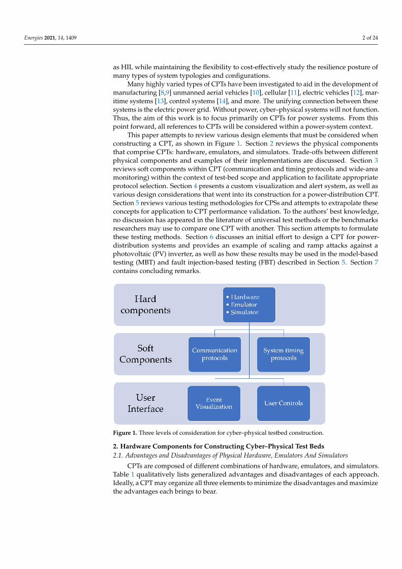
This paper attempts to review various design elements that must be considered whenconstructing a CPT, as shown in Figure 1. Section 2 reviews the physical componentsthat comprise CPTs: hardware, emulators, and simulators. Trade-offs between differentphysical components and examples of their implementations are discussed. Section 3reviews soft components within CPT (communication and timing protocols and wide-areamonitoring) within the context of test-bed scope and application to facilitate appropriateprotocol selection. Section 4 presents a custom visualization and alert system, as well asvarious design considerations that went into its construction for a power-distribution CPT.Section 5 reviews various testing methodologies for CPSs and attempts to extrapolate theseconcepts for application to CPT performance validation. To the authors’ best knowledge,no discussion has appeared in the literature of universal test methods or the benchmarksresearchers may use to compare one CPT with another. This section attempts to formulatethese testing methods. Section 6 discusses an initial effort to design a CPT for power-distribution systems and provides an example of scaling and ramp attacks against aphotovoltaic (PV) inverter, as well as how these results may be used in the model-basedtesting (MBT) and fault injection-based testing (FBT) described in Section 5. Section 7contains concluding remarks.
Figure 1. Three levels of consideration for cyber–physical testbed construction.
2. Hardware Components for Constructing Cyber–Physical Test Beds2.1. Advantages and Disadvantages of Physical Hardware, Emulators And Simulators
CPTs are composed of different combinations of hardware, emulators, and simulators.Table 1 qualitatively lists generalized advantages and disadvantages of each approach.Ideally, a CPT may organize all three elements to minimize the disadvantages and maximizethe advantages each brings to bear.
Energies 2021, 14, 1409 3 of 24
A purely physical–hardware-based CPT would provide the most ideal representationof real systems. One example of a purely hardware-based CPT is Idaho National Labo-ratory’s (INL’s) Critical Infrastructure Test Range Complex (CITRC) [15]. CITRIC boastsof containing its own fully functioning substation, which contains both distribution- andtransmission-class voltages and is ideally located for testing new power-grid solutions un-der a wide range of weather conditions. The testing and maintenance costs of this system,however, are very high compared to a real-time simulation with HIL setup. Hydro Quebecalso has a purely hardware-based distribution CPT [16]. This test bed operates at 25 kV andhas solar, wind, and storage assets attached; it is fed by its own independent transformerfrom a distribution substation. While these purely hardware-based CPT systems are idealfor testing and validation of system components, they require large amounts of real estateand are not practical for most research institutions. Although simulation and emulationhave less fidelity, they can help reduce cost and size constraints on a CPT.
To the authors’ best knowledge, a purely simulation- or emulation-based CPT wasnot found. A common strategy observed was to simulate the power-grid portion whileemulating or using real hardware for the cybernetic component or specific distribution-energy resources (DERs) [7,17,18]. Real-time simulation platforms—e.g., RTDS, Opal-RT,dSPACE, and Typhone HIL—have power systems models readily available to easily scalethe size of the power grid modeled in the CPT. Thus, real-time simulation provides acost-effective means to make the CPT more flexible and scalable.
Another advantage of simulation and emulation is the ability to connect test bedsseparated by large geographic distances [19]. Although data latency issues present somelimitations and must be addressed when considering a real-time simulation or emula-tion remote connection, the strategic expansion of test-bed assets may well be worth thetradeoff. One strategy is to separate a power-system model from the control-system inter-face, as outlined in [20], where one CPT specializes in power-system modeling, and theother in data visualization. Monti et al. reported on an intercontinental CPT connectionover real-time simulation, using high-voltage direct-current (HVDC) partitioning in thereal-time simulation and VILLAS framework [19]. The HVDC links require less informa-tion exchange compared to high-voltage alternating-current (HVAC) links to maintainsimulation-timing integrity. The VILLAS framework also reduces the communication over-head by reverting to a peer-to-peer style of communication, rather than using a centralizedcommunication authority.
Table 1. Generalized advantages and disadvantages of simulation, emulation, and hardware compo-nents for a cyber–physical system.
Simulation Emulation Hardware
Cost Low Medium HighFidelity Low Medium High
Scalability High Medium-high LowInteroperability Low Medium-high High
Computational expense Low High None
2.2. Hardware-, Emulator-, And Simulator-Based Representaitons of Physical, Cybernetic,and Cyber–Physical Elements within CPTs
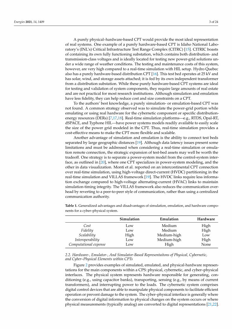
Figure 2 provides examples of simulated, emulated, and physical-hardware represen-tations for the main components within a CPS: physical, cybernetic, and cyber–physicalinterfaces. The physical system represents hardware responsible for generating, con-ditioning (e.g., using capacitor banks), transporting, sensing (e.g., by means of currenttransformers), and interrupting power to the loads. The cybernetic system comprisesdigital control devices that are able to manipulate physical components to facilitate efficientoperation or prevent damage to the system. The cyber–physical interface is generally wherethe conversion of digital information to physical changes on the system occurs or wherephysical measurements (typically analog) are converted to digital representations [21,22].
Energies 2021, 14, 1409 4 of 24
Each of the three components within a CPS are synchronized by time. A CPT attemptsto represent these three areas via simulation, emulation, physical hardware, or by somecombination thereof.
Physical system Cyber-physical interface Cyber system
Sim
ula
tio
n
Em
ula
tio
n
Ha
rd
wa
re
Power System Simulation
e.g. OPAL-RT, RTDS.
Power System Emulation
e.g. Typhoon HIL, V&D
electronics, FPGA
Power System Hardware
e.g. Solar panels, Switch
gear, Transmission lines
Communication Network
Simulation
e.g. GNS3, OPNET,
NetSim
Communication Network
Emulation
e.g. Emulab, NetEm
Communication Devices
e.g. PMU, RTU, LPDC,
router, switch
Control Center
Simulation
e.g. Python,
Webapps, Kafka
Control Center
Emulation
e.g. RTDMS,
OSISoft
Control Center
Servers/ aggregators
e.g. SPDC, Server
racks,
Figure 2. Different commercial solutions for representing physical, cybernetic, and cyber–physical components of acyber–physical test bed.
Real-time simulations are typically carried out on special platforms which producecalculations within fixed time steps. Due to their low cost in comparison to a purelyhardware system, simulations are typically a good way to start building a CPT. Until actualhardware is connected, the simulation does not need to be in real-time, which allowsfor faster debugging and development. While OPAL-RT and RTDS are very popularcommercial solutions for real-time power-grid simulaltions, others have attempted to adoptRaspberry Pi as a lower-cost alternative [23]. GNS3 and OPNET are network simulators andmay be used to interface with physical-system simulators, as discussed in [24]. The maindrawback of network simulators like GNS3 and OPNET is a lack of real-time functionality;thus, the authors in [24] opted to use network emulators running on a series of RaspberryPis, along with control algorithms written in Python.
Emulating an entire physical power grid is challenging because emulators typicallyattempt to mimic single components or bulk-grid inertia [25]. Collecting enough emulatorsto comprise a sizable grid would be expensive. In [26], a fully reconfigurable emulatedtest bed was reported to allow for greater time-scale flexibility, compared to real-timesimulations, and a wider range of voltage-class systems compared to actual hardware-basedtest beds. A LabView control-room interface was used to monitor and operate the powergrid; however, no mention of cybernetworks was provided. Current-transformer (CT) andvoltage-transformer (VT) measurements were simply fed directly from the emulation intoNI-CompactRIO running the control-room interface. In [24], an OPAL-RT system was usedto simulate the power grid while real-time Raspberry Pis, running NetEm, a Linux networkemulator, were used to emulate network-control traffic. DeterLab and ISEAGE are othernetwork-emulation tools that may be used to study network security for smart grids [27,28].Control-room software, such as RTDMS, GE iFIX SCADA, and Modbus, could be run in anemulated environment; however, there is no disadvantage to directly running control-roomsoftware on physical machines [29–31].
Energies 2021, 14, 1409 5 of 24
Cyber–physical systems may also include servers for data storage, in addition torunning supervisory control and data acquisition (SCADA) software [29–31]. Physical hard-ware that interfaces with measurement devices such as CTs, VTs, and phasor-measurementunits (PMUs), is location of the cyber–physical interface. Including these devices can bemore cost effective than attempting to emulate them and save on computation expense.Likewise, it is common to have microgrid components such as solar panels, batteries,and charge controllers because these are more affordable, and simulation or emulationresources may then be reserved for more-challenging tasks. Physical transmission or distri-bution lines, for example, are typically not practical for most institutions; thus, they requirereal-time simulation or emulation.
3. Soft Components for Cyber–Physical Testbeds3.1. Common Communication Protocols for CPSs and CPTs
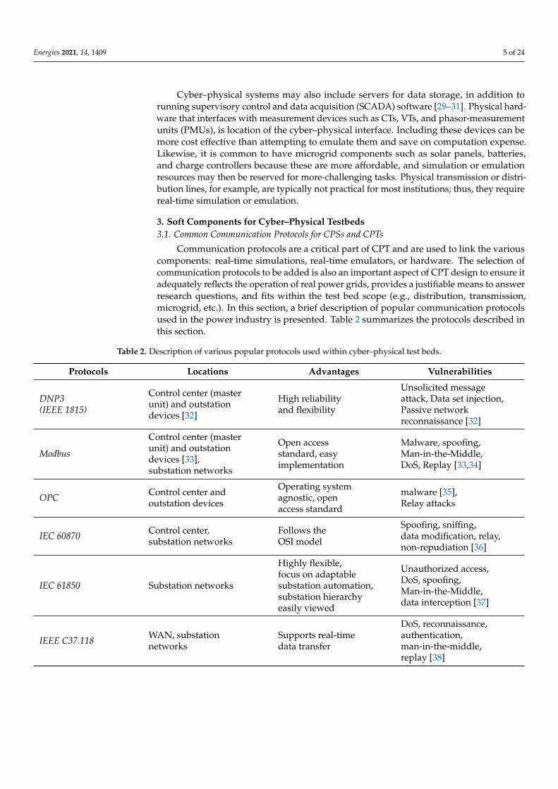
Communication protocols are a critical part of CPT and are used to link the variouscomponents: real-time simulations, real-time emulators, or hardware. The selection ofcommunication protocols to be added is also an important aspect of CPT design to ensure itadequately reflects the operation of real power grids, provides a justifiable means to answerresearch questions, and fits within the test bed scope (e.g., distribution, transmission,microgrid, etc.). In this section, a brief description of popular communication protocolsused in the power industry is presented. Table 2 summarizes the protocols described inthis section.
Table 2. Description of various popular protocols used within cyber–physical test beds.
Protocols Locations Advantages Vulnerabilities
DNP3(IEEE 1815)
Control center (masterunit) and outstationdevices [32]
High reliabilityand flexibility
Unsolicited messageattack, Data set injection,Passive networkreconnaissance [32]
Modbus
Control center (masterunit) and outstationdevices [33],substation networks
Open accessstandard, easyimplementation
Malware, spoofing,Man-in-the-Middle,DoS, Replay [33,34]
OPC Control center andoutstation devices
Operating systemagnostic, openaccess standard
malware [35],Relay attacks
IEC 60870 Control center,substation networks
Follows theOSI model
Spoofing, sniffing,data modification, relay,non-repudiation [36]
IEC 61850 Substation networks
Highly flexible,focus on adaptablesubstation automation,substation hierarchyeasily viewed
Unauthorized access,DoS, spoofing,Man-in-the-Middle,data interception [37]
IEEE C37.118 WAN, substationnetworks
Supports real-timedata transfer
DoS, reconnaissance,authentication,man-in-the-middle,replay [38]
Energies 2021, 14, 1409 6 of 24
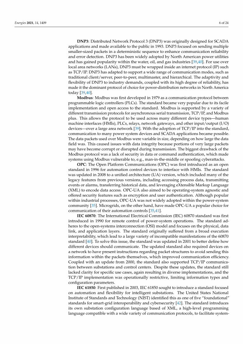
DNP3: Distributed Network Protocol 3 (DNP3) was originally designed for SCADAapplications and made available to the public in 1993. DNP3 focused on sending multiplesmaller-sized packets in a deterministic sequence to enhance communication reliabilityand error detection. DNP3 has been widely adopted by North American power utilitiesand has gained popularity within the water, oil, and gas industries [39,40]. For use overlocal area networks (LANs), DNP3 must be wrapped inside an internet protocol (IP) suchas TCP/IP. DNP3 has adapted to support a wide range of communication modes, such astraditional client/server, peer-to-peer, multimaster, and hierarchical. The adaptivity andflexibility of DNP3 to industry demands, coupled with its high degree of reliability, hasmade it the dominant protocol of choice for power-distribution networks in North Americatoday [39,40].
Modbus: Modbus was first developed in 1979 as a communication protocol betweenprogrammable logic controllers (PLCs). The standard became very popular due to its facileimplementation and open access to the standard. Modbus is supported by a variety ofdifferent transmission protocols for asynchronous serial transmission, TCP/IP, and Modbusplus. This allows the protocol to be used across many different device types—humanmachine interfaces (HMIs), PLCs, relays, network gateways, and other input/output (I/O)devices—over a large area network [39]. With the adoption of TCP/IP into the standard,communication to many power system devices and SCADA applications became possible.The data packets used over Modbus were variable in size, depending on how large the datafield was. This caused issues with data integrity because portions of very large packetsmay have become corrupt or disrupted during transmission. The biggest drawback of theModbus protocol was a lack of security in data or command authentication, which madesystems using Modbus vulnerable to, e.g., man-in-the-middle or spoofing cyberattacks.
OPC: The Open Platform Communications (OPC) was first introduced as an openstandard in 1996 for automation control devices to interface with HMIs. The standardwas updated in 2008 to a unified architecture (UA) version, which included many of thelegacy features from previous versions, including accessing process data, transmittingevents or alarms, transferring historical data, and leveraging eXtensible Markup Language(XML) to encode data access. OPC-UA also aimed to be operating-system agnostic andoffered security features such as encryption and user authentication. Although popularwithin industrial processes, OPC-UA was not widely adopted within the power-systemcommunity [35]. Microgrids, on the other hand, have made OPC-UA a popular choice forcommunication of their automation controls [35,41].
IEC 60870: The International Electrical Commission (IEC) 60870 standard was firstintroduced in 1990 for remote control of power-system operations. The standard ad-heres to the open-systems interconnection (OSI) model and focuses on the physical, datalink, and application layers. The standard originally suffered from a broad executioninterpretability, which lead to a large variety of incompatible manifestations of the 60870standard [40]. To solve this issue, the standard was updated in 2001 to better define howdifferent devices should communicate. The updated standard also required devices ona network to have present instructions regarding packet structures to avoid sending thisinformation within the packets themselves, which improved communication efficiency.Coupled with an update from 2000, the standard also supported TCP/IP communica-tion between substations and control centers. Despite these updates, the standard stilllacked clarity for specific use cases, again resulting in diverse implementations, and theTCP/IP implementation was operationally restrictive, limiting information types andconfiguration parameters.
IEC 61850: First published in 2003, IEC 61850 sought to introduce a standard focusedon automation and flexibility for intelligent substations. The United States NationalInstitute of Standards and Technology (NIST) identified this as one of five “foundational”standards for smart-grid interoperability and cybersecurity [42]. The standard introducesits own substation configuration language based of XML, a high-level programminglanguage compatible with a wide variety of communication protocols, to facilitate system-
Energies 2021, 14, 1409 7 of 24
wide component configuration. Substation communication is binned into one of threedifferent categories: process (e.g., I/O devices and sensors), unit (e.g., protection andsubstation devices), and substation (the control computer or operators control HMI) levels.Within each of these communication levels, a series of protection and control functions aredefined for various objects (also referred to as logic nodes (LNs)). Each LN correspondsto various substation device functions and can be grouped to logic devices that representintelligent electrical devices (IEDs). The protocol also includes provisions for transmittinggeneric object-oriented substation events (GOOSE). Although previous protocols allowedfor custom applications to configure and automate substation settings and operations, IEC61850 includes specific instructions for how to do this, with definitions for over 100 LNs andmore than 2000 data objects or data attributes. Additionally, users can access informationhierarchies based on all LNs and objects to gain a sense of how substations are organizedlogically. The main drawback of IEC 61850 is its higher complexity compared to legacyprotocols. IEC 61850 is described as having a steep learning curve and requiring significanteffort to implement [39]. Because of these difficulties and the lack of manpower to supporta significant upgrade, IEC 61850 has not been widely adopted in North America [43,44].
IEEE C37.118: Establised in 2005, this protocol was designed for real-time exchangeof synchronized phasor-measurement data between power-system equipment [45]. Initialversions included both measurement and real-time data-transfer requirements. It providesan open-access method to facilitate the development and use of synchrophasors, allowingdata transmission and accretion within a phasor–measurement system [45]. IEEE StandardC37.118-2005 was eventually split into two standards, one with measurement requirementsand the other with the data-transfer requirements. This allowed for the use of IEEEC37.118 with other communication protocols. Further, this protocol was created withsufficient flexibility to account for future developments and enable a smooth transition ofsynchrophasor systems to new protocols as necessitated [45].
3.2. Timing and Data Synchronization
Modern smart grids commonly consist of interconnected hardware and software com-ponents in distributed substations, communicating with each other to achieve a commongoal [46]. In order to function and make decisions properly, the correct timing of data mea-sured throughout geographically distributed sensors in the system must be considered [47].Therefore, time synchronization is one of the primary elements in smart grids that enablesaccurate monitoring and protection and optimal control [47,48]. Thus, timing is also criticalfor CPTs.
The requirement for time synchronization varies from one microsecond to hundredsof nanoseconds, depending on the device used, customer demands, and application ofinterest [48]. For example, traveling-wave fault detection requires synchronization on theorder of hundreds of nanoseconds to precisely locate a fault [48]. In [49], a traveling-wavefault-detection CPT was designed using an OPAL-RT system with a field-programmablegate array (FPGA) to generate transient signals over fiberoptic cables with a 500 ns timestep. This CPT allowed for testing the detection functionality for various fault-locatordevices. A synchrophasor or phasor measurement unit (PMU), on the other hand, measuresthe magnitude and phase angle to determine the health of the electrical grid and onlyrequires 30 observations per second [50]. Adikari et al. built a CPT to explore PMU-control interactions with the power grid by leveraging RTDS and various PMU HILpossibilities [51]. They generated several time-synchronized cyber–physical data setsof various cyberattacks in order to aid in intrusion-detection sensor development.
The time synchronization requirements for power grids are often satisfied usingGPS- or protocol-based time synchronization [48]. In GPS-based time synchronization,a standard-reference atomic time signal into substations’ components is used. Protocol-based time synchronization uses network-based time-distribution protocols such as theNetwork Time Protocol (NTP).
Energies 2021, 14, 1409 8 of 24
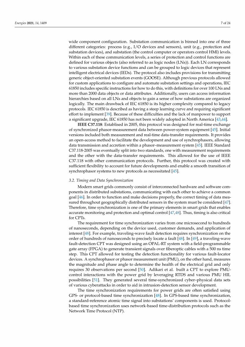
Popular methods currently used for time distribution in smart grids described hereare summarized in Table 3:
• Global Navigation Satellite System (GNSS) is a system of satellites with global cover-age, facilitating geospatial positioning and precise time [50]. GNSS is an Americancompany. GLONASS is a similar system owned by the Russian state corporationRoscosmos. Time references provided by these GPS systems have accuracy to lessthan 100 nanoseconds, sufficient for most power-system applications [50].
• The American Inter Range Instrumentation Group (IRIG) contains several standards,including IRIG Standard 200-98, IRIG-B, and IRIG Standard 200-04. This method usesa continuous stream of binary data to distribute time information. IRIG-B is the mostcommon standard; it facilitates geographically separated locations synchronizing to asingle time source [50].
• Network Time Protocol (NTP) is designed to synchronize clocks of multiple computersover a packet network. In order to synchronize clocks over the network, the networkdelay between clocks must be known. Therefore, the accuracy of NTP depends onnetwork traffic. The accuracy of this method on LANs is around 1 millisecond and ison the order of tens of milliseconds for wide area networks (WANs) [50].
• IEEE 1588 is designed for systems which require highly accurate time synchronization.Rather than using packet network, this approach uses “hardware time-stamping” todistribute time. The accuracy of this method lies under a microsecond [50] and is apopular standard to synchronize clocks on distributed systems.
Table 3. Description of various timing synchronization schemes used within cyber–physical testbeds.
Protocols Applications Advantages Vulnerabilities
GNSS Synchrophasor [48] Time synchronization acrosslarge geographic areas Spoofing [52], DoS [53]
IRIG(IEEE 1344) Synchrophasors Contains a clock,
quality indicatorDoS, eavesdropping(if not encrypted) [54]
NTP
Substation, microgrid,control center, powerelectronics outstationdevices, SCADA
Universally adoptedMalicious packetdelays [55], ARPspoofing [55]
IEEE 1588 Control center,substation networks High degree of accuracy Time synchronization
attacks [56]
Most often in CPTs, the timing component is handled by the real-time simulator,with little need for timing network protocols. In [51], for example, network protocol IEEEC37.118 was used to communicate between various PMU devices in studying wide-areameasurement systems, but provided no mention of timing protocols used in the study,if there were any. Many PMU devices typically have internal GPS clocks that are ableto time-stamp measurements [29]. Additionally, most CPT components are within closeproximity to each other, which negates the need to account for data transmission over longdistances. However, the SCADA Security Laboratory and Power and Energy ResearchLaboratory at Mississippi State University comprise two remote sites on campus, one ofwhich contains a PMU and GPS substation control unit [14]. This would enable variousstudies involving attacks against network timing synchronization to explore potentialimpacts on various control schemes and physical-system typologies (simulated by RTDSand HITL).
The design goals of the CPT may also impact what communication and timing stan-dards are pared. For example, an automated control scheme using peer-to-peer communi-cation among various IDEs would benefit from IEC 61850, which allows for high-resolution,
Energies 2021, 14, 1409 9 of 24
low-latency transmission of contextualized (e.g., providing the device of origin) data [57].A more precise timing protocol, such as the IEEE 1588, may be required for those use cases.DNP3 was designed for SCADA communication [58] and can be used for power-gridautomation [59]; however, it is not considered to be sufficiently flexible to handle all con-ceivable scenarios within the smart grid and, in particular, subsecond device controls [60].However, DNP3 was found to be a much more resilient protocol to packet rendering, datacorruption, jitter, and bandwith limitations than IEC 61850 [61]. A CPT that focuses on pro-viding situational awareness and human-in-the-loop studies might more strongly considerDNP3, which supports a wide range of timing protocols. Modbus is most advantageouswhen dealing with serial communication [62]. Although, Modbus is capable of transmittingat faster rates than DNP3 [63,64] and is considered to be an important protocol for smartgrids [62], it is less popular in North America and Europe [62]. Like DNP3, Modbus is usedfor system monitoring and supports a wide range of timing protocols [65].
3.3. Wide-Area Situational Awareness
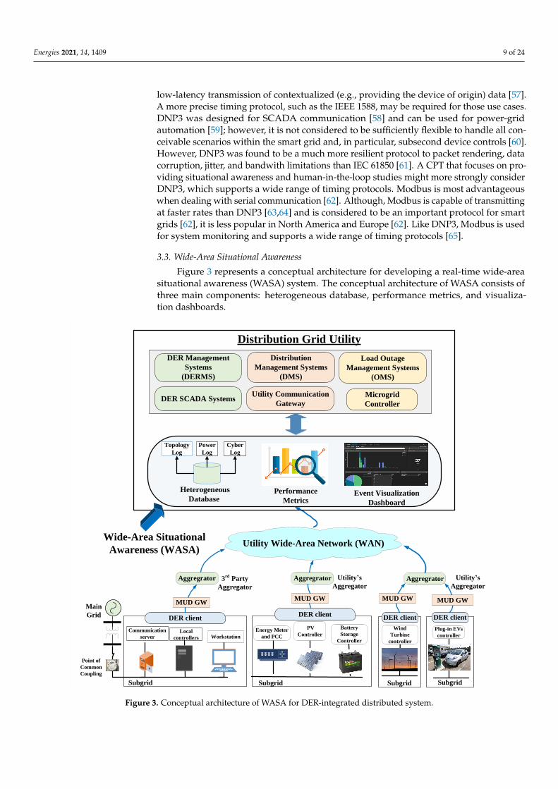
Figure 3 represents a conceptual architecture for developing a real-time wide-areasituational awareness (WASA) system. The conceptual architecture of WASA consists ofthree main components: heterogeneous database, performance metrics, and visualiza-tion dashboards.
DER Management
Systems
(DERMS)
Distribution Grid Utility
Distribution
Management Systems
(DMS)
Load Outage
Management Systems
(OMS)
DER SCADA Systems Utility Communication
Gateway
Microgrid
Controller
Communication
serverLocal
controllers
DER client
Workstation
Subgrid
Battery
Storage
Controller
Subgrid
Plug-in EVs
controller
Subgrid
DER client
Subgrid
DER client
MUD GW
Wind
Turbine
controller
Energy Meter
and PCC
MUD GW
Aggregrator Aggregrator
MUD GW
Utility Wide-Area Network (WAN)
Point of
Common
Coupling
Main
Grid
Aggregrator
Heterogeneous
DatabaseEvent Visualization
Dashboard
Wide-Area Situational
Awareness (WASA)
Performance
Metrics
Topology
Log
Power
Log
Cyber
Log
PV
Controller
DER client
MUD GW
3rd
Party
Aggregator
Utility’s
Aggregator
Utility’s
Aggregator
Figure 3. Conceptual architecture of WASA for DER-integrated distributed system.
Energies 2021, 14, 1409 10 of 24
The control center of a DER integrated distribution grid receives multidimensionalgrid measurements from DER client nodes, system logs from network sensors, firewallalerts from network sensors, and topology logs from other management systems. There-fore, a heterogeneous database system (HDS) is required to store these data sets for lateruse in other applications, such as resilience metrics, forensic analysis, and wide-area con-trol (WAC). In addition, it can be used to facilitate event visualization through real-timeprocessing of incoming data.
4. User interface for Cyber–Physical TestbedsEvent Visualization Dashboard
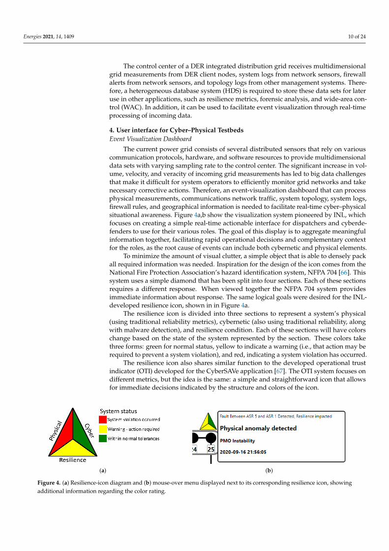
The current power grid consists of several distributed sensors that rely on variouscommunication protocols, hardware, and software resources to provide multidimensionaldata sets with varying sampling rate to the control center. The significant increase in vol-ume, velocity, and veracity of incoming grid measurements has led to big data challengesthat make it difficult for system operators to efficiently monitor grid networks and takenecessary corrective actions. Therefore, an event-visualization dashboard that can processphysical measurements, communications network traffic, system topology, system logs,firewall rules, and geographical information is needed to facilitate real-time cyber–physicalsituational awareness. Figure 4a,b show the visualization system pioneered by INL, whichfocuses on creating a simple real-time actionable interface for dispatchers and cyberde-fenders to use for their various roles. The goal of this display is to aggregate meaningfulinformation together, facilitating rapid operational decisions and complementary contextfor the roles, as the root cause of events can include both cybernetic and physical elements.
To minimize the amount of visual clutter, a simple object that is able to densely packall required information was needed. Inspiration for the design of the icon comes from theNational Fire Protection Association’s hazard identification system, NFPA 704 [66]. Thissystem uses a simple diamond that has been split into four sections. Each of these sectionsrequires a different response. When viewed together the NFPA 704 system providesimmediate information about response. The same logical goals were desired for the INL-developed resilience icon, shown in in Figure 4a.
The resilience icon is divided into three sections to represent a system’s physical(using traditional reliability metrics), cybernetic (also using traditional reliability, alongwith malware detection), and resilience condition. Each of these sections will have colorschange based on the state of the system represented by the section. These colors takethree forms: green for normal status, yellow to indicate a warning (i.e., that action may berequired to prevent a system violation), and red, indicating a system violation has occurred.
The resilience icon also shares similar function to the developed operational trustindicator (OTI) developed for the CyberSAVe application [67]. The OTI system focuses ondifferent metrics, but the idea is the same: a simple and straightforward icon that allowsfor immediate decisions indicated by the structure and colors of the icon.
(a) (b)
Figure 4. (a) Resilience-icon diagram and (b) mouse-over menu displayed next to its corresponding resilience icon, showingadditional information regarding the color rating.

Energies 2021, 14, 1409 11 of 24
The left-most section of the icon is concerned with the physical health of the system.This can include anything that is related to the physical behavior of any componentswithin the power grid (e.g., faults, under voltages, generators nearing capacity limits).The right section of the icon is associated with the cybernetic health of the system, includingerroneous connections, failed connections, failed login attempts, suspicious activity, or virusdetection. The final (bottom) section displays the resilience indications and uses theadaptive-capacity metric discussed in [68–71]. In brief, the adaptive capacity of a deviceshows how much additional real and reactive power could be used to respond to andrecover from a disturbance based on a components thermal limits. This metric easilyaggregates the adaptive capacity of collections of grid assets. Colors may be assigned inaccordance with NERC or IEEE standards with regards to thermal capacity. Furthermore,the icon has a mouse-over feature shown in Figure 4b, which allows for immediate messagesto be presented without the delay associated with an actual drill down.
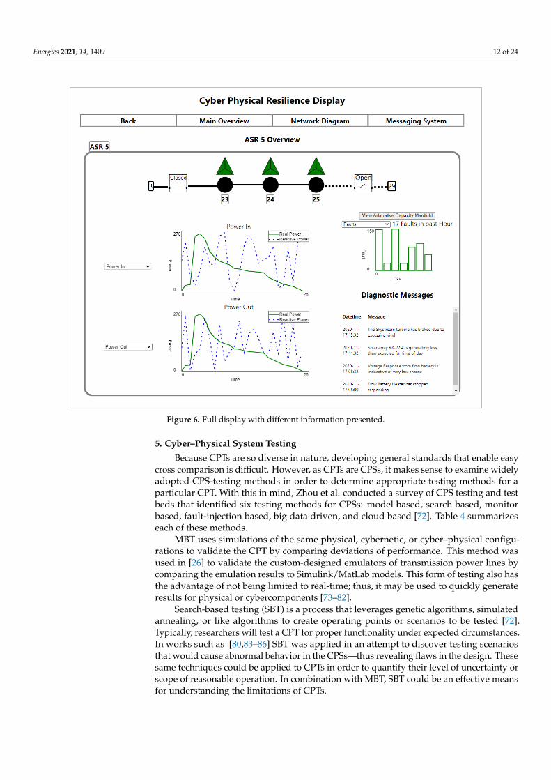
The icon can be associated with single components or aggregations. Figure 5 showsan example of the visualization for the IEEE 33 bus system with several of the bussesgrouped into aggregated system resources (ASRs). Each of the different ASR units canbe selected to drill down into lower levels that display the ASR’s internal components,as shown in Figure 6, where each bus now possesses its own resilience icon. By displayinginformation relevant to predefined levels of specific aggregated-component resolutions,the user is easily able to locate relevant information without becoming overwhelmed.The interconnections between all of the different elements also represent different states,such as normally closed, closed, normally open, or opened (Figure 5). Thus, the whole stateof the system can be visualized accurately to maintain a high degree of state awareness.
Figure 5. Full display with different information presented (callouts on powerlines have been added for clarity).
Energies 2021, 14, 1409 12 of 24
Figure 6. Full display with different information presented.
5. Cyber–Physical System Testing
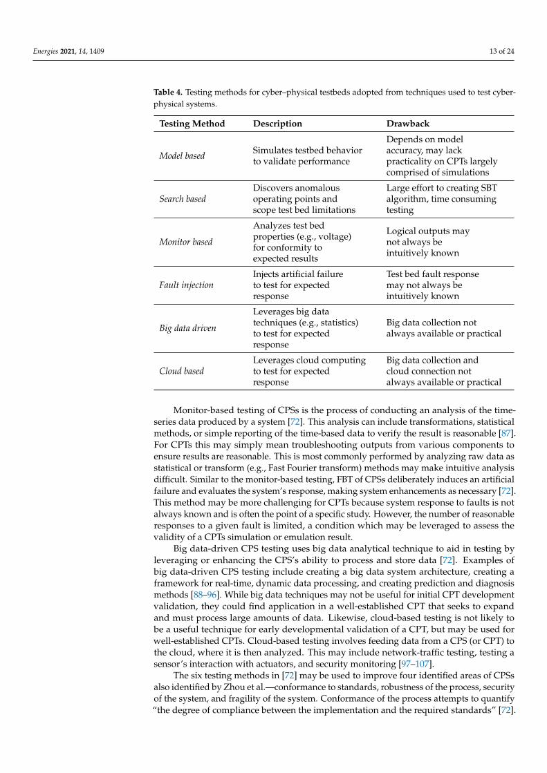
Because CPTs are so diverse in nature, developing general standards that enable easycross comparison is difficult. However, as CPTs are CPSs, it makes sense to examine widelyadopted CPS-testing methods in order to determine appropriate testing methods for aparticular CPT. With this in mind, Zhou et al. conducted a survey of CPS testing and testbeds that identified six testing methods for CPSs: model based, search based, monitorbased, fault-injection based, big data driven, and cloud based [72]. Table 4 summarizeseach of these methods.
MBT uses simulations of the same physical, cybernetic, or cyber–physical configu-rations to validate the CPT by comparing deviations of performance. This method wasused in [26] to validate the custom-designed emulators of transmission power lines bycomparing the emulation results to Simulink/MatLab models. This form of testing also hasthe advantage of not being limited to real-time; thus, it may be used to quickly generateresults for physical or cybercomponents [73–82].
Search-based testing (SBT) is a process that leverages genetic algorithms, simulatedannealing, or like algorithms to create operating points or scenarios to be tested [72].Typically, researchers will test a CPT for proper functionality under expected circumstances.In works such as [80,83–86] SBT was applied in an attempt to discover testing scenariosthat would cause abnormal behavior in the CPSs—thus revealing flaws in the design. Thesesame techniques could be applied to CPTs in order to quantify their level of uncertainty orscope of reasonable operation. In combination with MBT, SBT could be an effective meansfor understanding the limitations of CPTs.
Energies 2021, 14, 1409 13 of 24
Table 4. Testing methods for cyber–physical testbeds adopted from techniques used to test cyber-physical systems.
Testing Method Description Drawback
Model based Simulates testbed behaviorto validate performance
Depends on modelaccuracy, may lackpracticality on CPTs largelycomprised of simulations
Search basedDiscovers anomalousoperating points andscope test bed limitations
Large effort to creating SBTalgorithm, time consumingtesting
Monitor based
Analyzes test bedproperties (e.g., voltage)for conformity toexpected results
Logical outputs maynot always beintuitively known
Fault injectionInjects artificial failureto test for expectedresponse
Test bed fault responsemay not always beintuitively known
Big data driven
Leverages big datatechniques (e.g., statistics)to test for expectedresponse
Big data collection notalways available or practical
Cloud basedLeverages cloud computingto test for expectedresponse
Big data collection andcloud connection notalways available or practical
Monitor-based testing of CPSs is the process of conducting an analysis of the time-series data produced by a system [72]. This analysis can include transformations, statisticalmethods, or simple reporting of the time-based data to verify the result is reasonable [87].For CPTs this may simply mean troubleshooting outputs from various components toensure results are reasonable. This is most commonly performed by analyzing raw data asstatistical or transform (e.g., Fast Fourier transform) methods may make intuitive analysisdifficult. Similar to the monitor-based testing, FBT of CPSs deliberately induces an artificialfailure and evaluates the system’s response, making system enhancements as necessary [72].This method may be more challenging for CPTs because system response to faults is notalways known and is often the point of a specific study. However, the number of reasonableresponses to a given fault is limited, a condition which may be leveraged to assess thevalidity of a CPTs simulation or emulation result.
Big data-driven CPS testing uses big data analytical technique to aid in testing byleveraging or enhancing the CPS’s ability to process and store data [72]. Examples ofbig data-driven CPS testing include creating a big data system architecture, creating aframework for real-time, dynamic data processing, and creating prediction and diagnosismethods [88–96]. While big data techniques may not be useful for initial CPT developmentvalidation, they could find application in a well-established CPT that seeks to expandand must process large amounts of data. Likewise, cloud-based testing is not likely tobe a useful technique for early developmental validation of a CPT, but may be used forwell-established CPTs. Cloud-based testing involves feeding data from a CPS (or CPT) tothe cloud, where it is then analyzed. This may include network-traffic testing, testing asensor’s interaction with actuators, and security monitoring [97–107].
The six testing methods in [72] may be used to improve four identified areas of CPSsalso identified by Zhou et al.—conformance to standards, robustness of the process, securityof the system, and fragility of the system. Conformance of the process attempts to quantify“the degree of compliance between the implementation and the required standards” [72].
Energies 2021, 14, 1409 14 of 24
More simply stated, the degree of likeness between the intended result and the actual result.For the power grid, this may mean measuring the deviation of voltage or frequency ofpower delivered to the loads from adopted standards like IEEE or the American NationalStandards Institute. The robustness of the process refers to assessing the fault tolerance ofa system. The security of the system assesses any physical- or cybersecurity issues withinthe CPSs. The fragility of the system refers to a CPS’s ability to continue operation withinacceptable tolerances despite abnormal perturbations to operating conditions (this is alsoknown as system resilience). CPTs are an effective way to assess each of these four areas.In order to develop and validate CPTs, however, MBT, SBT, and monitor-based testing maybe effective tools to ensure accurate behavior. Fault-injection, big data, and cloud-basedtesting, on the other hand, may be limited to more-intuitive use cases for functionalityvalidation in already established test beds.
6. Example of Cyber–Physical Analysis And Design6.1. Simulation-Based Case Study
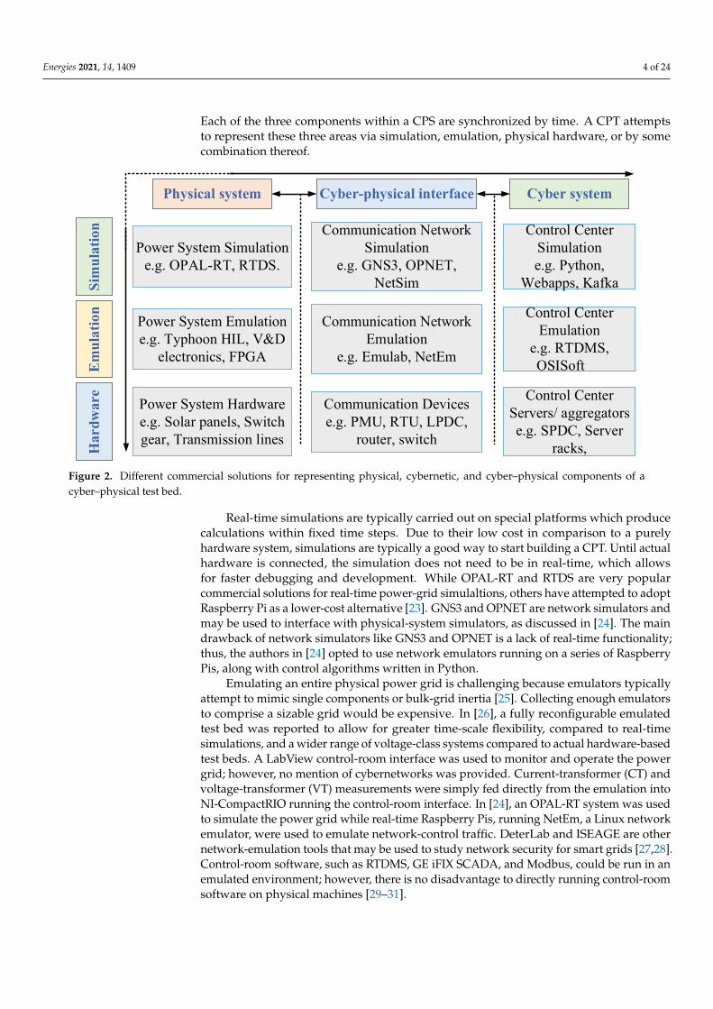
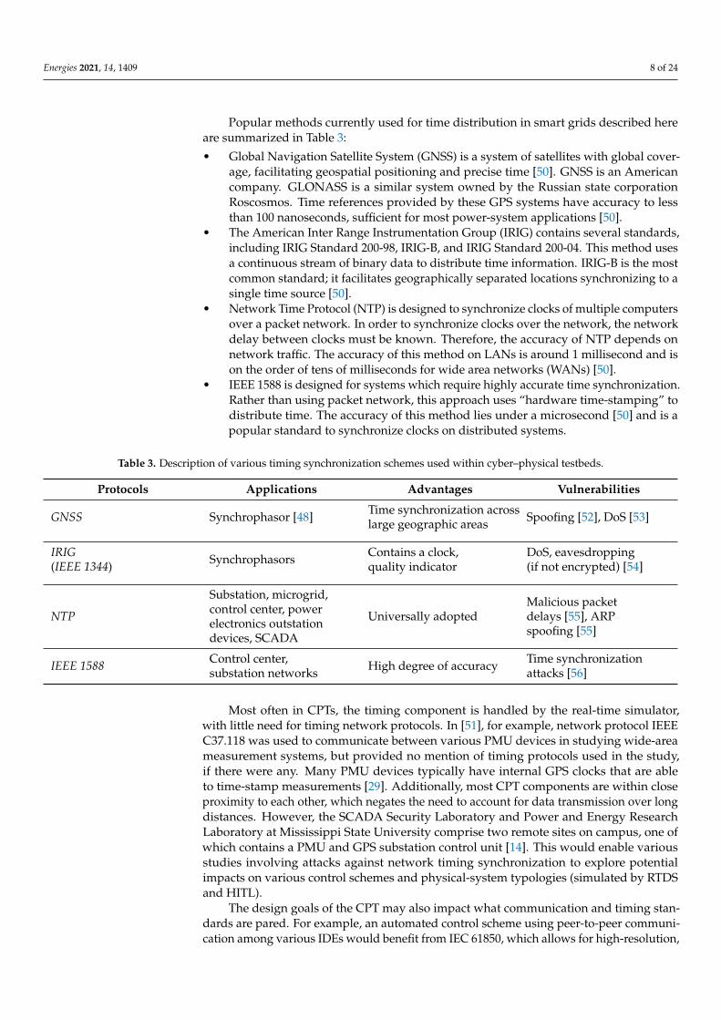
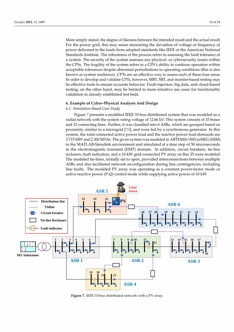
Figure 7 presents a modified IEEE 33-bus distributed system that was modeled as aradial network with the system rating voltage of 12.66 kV. This system consists of 33 busesand 32 connecting lines. Further, it was classified into 6 ASRs, which are grouped based onproximity, similar to a microgrid [70], and were fed by a synchronous generator. In thissystem, the total connected active power load and the reactive power load demands are3.715 MW and 2.300 MVAr. The given system was modeled in ARTEMiS/SSN (eMEGASIM)in the MATLAB-Simulink environment and simulated at a time step of 50 microsecondsin the electromagnetic transient (EMT) domain. In addition, circuit breakers, tie-linereclosers, fault indicators, and a 10-kW grid-connected PV array on Bus 25 were modeled.The modeled tie-lines, initially set to open, provided interconnections between multipleASRs and also facilitated network reconfiguration during line contingencies, includingline faults. The modeled PV array was operating as a constant power-factor mode oractive-reactive power (P-Q) control mode while supplying active power of 10 kW.
21
MV Substation
3 4 765 8 9 10 1112
13 14 15 16 17
18
26 27 28 29 30 31
23 24 25
19 2021 22
ASR 5
ASR 6
ASR 1
ASR 4
ASR 3ASR 2
32 33
PVDistribution line
Circuit breaker
Tie-line Reclosure
Fault indicator
Tieline
Cyber
Attack
Figure 7. IEEE 33-bus distributed network with a PV array.
Energies 2021, 14, 1409 15 of 24
6.2. Cyber-Attack Vectors
The increased dependency on information and communication technologies (ICTs) hasmade power systems increasingly vulnerable to various cyber–physical attacks [108]. Theseattacks range from reconnaissance attacks, the objective of which is to gain information onthe system, to attacks that attempt to disrupt the system such as denial of service (DoS),replay, or data-insertion attacks [109,110]. DoS attacks are some of the most-commonapproaches to disrupt communication networks. DoS can be used by an adversary toaffect the dynamic performance of power systems, leading to unstable behavior [111].Replay attacks capture real messages to be replayed later so as to obfuscate the current stateof the system [112,113]. False-data-injection attacks manipulate communication data tocreate confusion and trigger incorrect responses that disrupt the system while preventingdetection [114]. Ramp and scaling attacks are examples of false-data-injection attacks.These attacks consist of making small or gradual modifications to true measurements toconfuse the system and trigger control actions that are not appropriate for the actual stateof the system. Ramp attacks are gradual modifications of true measurements while scalingattacks add or subtract a small percentage value to measurements. These types of attackscan be specifically tuned to cause disruption while evading detection by carefully choosingthe scale of the modifications. Using a representative pool of cyberattacks to validatedetection and mitigation mechanisms is essential for cyber–physical system testing.
As an illustration of FBT, ramp and scaling attacks against the PV-integrated distribu-tion system (Figure 7) were considered. Further, it was assumed that the inverter of the PVarray was compromised, and the attacker was able to modify the internal setting of theinverter by applying the following attack templates.
1. Scaling attack: This attack involves modifying the measurement signal to a higher orlower value, depending on the scaling attack parameter, λscale, as shown in (1).
2. Ramp attack: This attack vector involves adding a time-varying ramp signal to theinput control signal based on a ramp signal parameter, λramp, as shown in (2).
Pscale = Pi(1 + λscale) (1)
Pramp = Pi + λramp ∗ t (2)
6.3. Results and Discussions
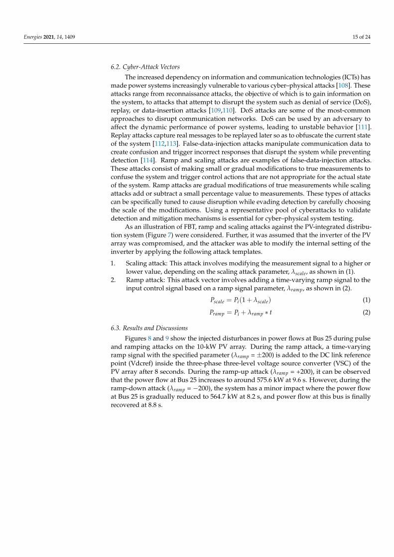
Figures 8 and 9 show the injected disturbances in power flows at Bus 25 during pulseand ramping attacks on the 10-kW PV array. During the ramp attack, a time-varyingramp signal with the specified parameter (λramp = ±200) is added to the DC link referencepoint (Vdcref) inside the three-phase three-level voltage source converter (VSC) of thePV array after 8 seconds. During the ramp-up attack (λramp = +200), it can be observedthat the power flow at Bus 25 increases to around 575.6 kW at 9.6 s. However, during theramp-down attack (λramp = −200), the system has a minor impact where the power flowat Bus 25 is gradually reduced to 564.7 kW at 8.2 s, and power flow at this bus is finallyrecovered at 8.8 s.
Energies 2021, 14, 1409 16 of 24
7.8 8 8.2 8.4 8.6 8.8 9 9.2 9.4 9.6
565
570
575
580Ramp-up Attack
7.8 8 8.2 8.4 8.6 8.8 9 9.2 9.4 9.6
Time (second)
564
565
566
567
568
569
Po
wer
flo
ws
at b
us
25 (
kW)
Ramp-down Attack
Attack Initiated
Attack Initiated
Figure 8. Power flows at bus 25 during ramp-up and ramp-down attacks.
7.8 8 8.2 8.4 8.6 8.8 9 9.2 9.4 9.6560
570
580
590
600Scale-up Attack
7.8 8 8.2 8.4 8.6 8.8 9 9.2 9.4 9.6
Time (second)
562
564
566
568
570
572
Po
wer
flo
ws
at b
us
25 (
kW)
Scale-down Attack
Attack Initiated
Attack Initiated
Figure 9. Power flows at bus 25 during scale-up and scaling-down attacks.
Energies 2021, 14, 1409 17 of 24
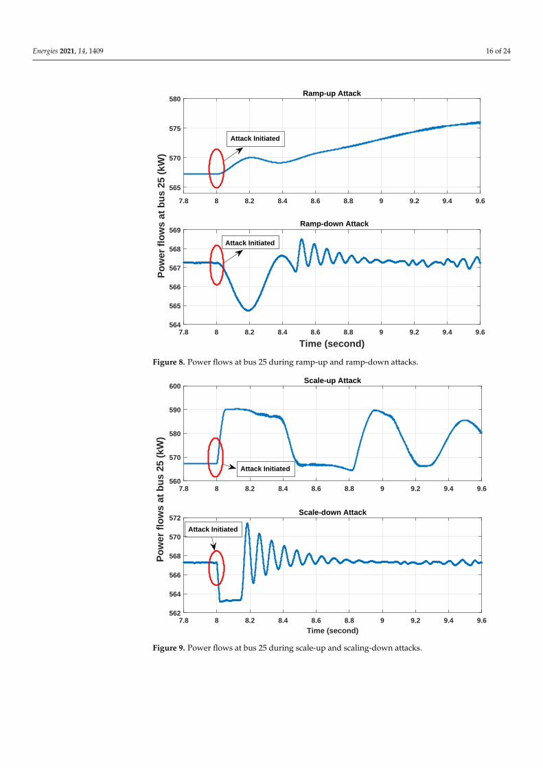
During the scaling attack, the Vdcref was modified by half its original value (λscale =±0.5), and this attack was performed after 8 s. During the scale-up ((λscale = +0.5) on Vdcref,the initial power flow was increased to 590 kW at 8.05 s and exhibited a major oscillationwith low frequency. During the scale-down ((λscale = −0.5), the power flow was reducedto 563.4 kW, and a minor oscillation was observed, with high-frequency components ascompared to the previous scale-up attack. From these two experiments, it can be inferredthat the ramp-up and scale-up attacks have more severe impact than do ramp-down andscale-down attacks. Further, it can be concluded that the impact of cyberattacks dependson the nature of attack, and the scaling attack injects more transient instability than a rampattack because of its instantaneous change of the signal to extreme values. This result wasexpected and is an example of FBT validation, discussed in Section 5 as large instantaneouschanges (scale attack) should produce more power-flow instability than gradual changes(ramp attack). Additionally, emulated or hardware-based test beds of the IEEE 33 bussystem may use models like this to validate their performance (i.e., MBT, also discussed inSection 5).
6.4. Potential Mitigation Solutions for Data-Integrity Attacks
There exist several approaches to development of intrusion-detection systems (IDSs)to detect different classes of data-integrity attacks, which include pulse and scaling attacks.In general, these approaches can be classified into two broad categories: signature-basedIDS and anomaly-based IDSs.
1. Signature-based IDS relies on network traffic to detect different classes of data-integrity attacks based on the defined attack-signature database. Several IDS tools,including BRO (Zeek), Snort, Firestorm, and Spade can be applied in developingsignature-based IDS in real-time in a cyber–physical test bed environment.
2. Anomaly-based IDS detects intrusions based on deviations from the normal behaviorof the distribution system. It includes different types, such as model-based IDS,machine-learning-based IDS, multi-agent-based IDS. These are discussed below.
(a) Model-based IDS utilizes the current grid information, historical measure-ments, and other relevant information to develop a baseline model and detectsattacks based on the statistical and temporal correlation analysis of incominggrid measurements.
(b) Learning-based IDS applies machine learning, deep-learning, and data miningalgorithms to identify different types of stealthy and sophisticated attacksusing grid measurements. Further, it also distinguishes them from other events,including line faults, extreme weather events, etc. For example, decision treealgorithms can be utilized in detecting different data integrity attacks usingsynchrophasor measurements in real-time.
(c) Multi-agent-based IDS consists of several distributed agents that utilize bothcyber and physical measurements to develop anomaly detection algorithmsthrough agent co-ordination and information sharing. Further, it can be uti-lized for developing attack-resilient protection and control schemes that candetect attacks at an early stage and initiate necessary mitigation strategies torestore the normal operation of the power grid.
7. Conclusions
The design tradeoffs between various elements in a CPT test bed can be broken downinto three different categories: physical components, soft components, and user interfaces.Representations of CPTs physical, cybernetic, cyber–physical parts were reviewed withinthe context of balancing cost, computational expense, and fidelity. The scalability ofsimulated systems within CPTs enables them to be highly cost effective, but with a lowerresolution than more computationally expensive system emulators. Physical hardware wasconsidered to have no computational expense, but had the highest financial cost associatedwith operation and maintenance. Relevant communication protocols were described,
Energies 2021, 14, 1409 18 of 24
as were timing considerations to be used based on the goals of the CPT. Wide-area testbed representations with data visualization aspects of CPTs were also explored. Methodsfor testing CPSs were leveraged as potential avenues for developing generalized testingmethods to validate the performance of CPTs. An initial demonstration on an IEEE 33bus system, together with examples for how MBT and FBT may be applied to validatethe CPT performance, was also discussed. Lastly, detection strategies for these types ofattacks were considered. The authors hope to inspire more discussion about CPT testingand validation to enable better comparison among different test beds. CPTs enable easyexploration for improving CPSs that impact everyday life. Thus, developing effectivemethods to ensure proper functionality and better defining the limitations of these CPTs isan important subject in need of further exploration.
Author Contributions: Conceptualization, B.V., C.R., and M.M.; methodology, B.V., V.K.S., J.L. andC.R.; software, J.L., T.P., and V.K.S.; validation, J.L., and V.K.S.; formal analysis, B.V. and V.K.S.;investigation, B.V. and V.K.S.; Project administration B.V.; writing—original draft preparation, B.V.,V.K.S., R.I., D.L.M., C.S.W. and J.L.; writing—review and editing, B.V., V.K.S., R.I., D.L.M., C.S.W., J.L.,T.P., C.R. and M.M.; supervision, B.V.; funding acquisition, C.R. All authors have read and agreed tothe published version of the manuscript.
Funding: This research was completed by Idaho National Laboratory with funding from the U.S.Department of Energy. Idaho National Laboratory is operated by Battelle Energy Alliance, LLC,under contract No. DE AC07-05ID14517.
Acknowledgments: This material is based upon work supported by the U.S. Department of Energy’sOffice of Energy Efficiency and Renewable Energy (EERE) under the Solar Energy Technology OfficeAward Number DE-0008775. Effort performed through Department of Energy under U.S. DOE IdahoOperations Office , Contract DE-AC07-05ID14517, as part of the Resilient Control and InstrumentationSystems (ReCIS) program of Idaho National Laboratory.
Conflicts of Interest: The authors declare no conflict of interest. The funders had no role in the designof the study; in the collection, analyses, or interpretation of data; in the writing of the manuscript; orin the decision to publish the results.
AbbreviationsThe following abbreviations are used in this manuscript:
ASR Aggregated system resourcesCITRC Critical Infrastructure Test Range ComplexCPS Cyber–physical systemsCPT Cyber–physical testbedsCT Current transformerDER Distributed energy resorcesDNP3 Distributed network protocol 3DoS Denial of serviceEMT Electromagnetic transientFBT Fault injection-based testingGNSS Global Navigation Satellite SystemGOOSE Generic object-oriented substation eventsHIL Hardware in the loopHMI Human machine interfacesHVAC High voltage alternating currentHVDC High voltage direct currentICT Information communication technologies
Energies 2021, 14, 1409 19 of 24
IDS Intrusion detection systemsIEC International Electrical CommissionIED Intelligent electronic deviceIEEE Institute of Electrical and Electronics EngineersINL Idaho National LaboratoryIP Internet protocolIRIG American Inter Range Instrumentation GroupI/O Input/outputLAN Local area networkMBT Model based testingNIST National Institute of StandardsNTP Network time protocolOPC Open platform communicationsOSI Open systems interconnectionOTI Operational trust indicatorPLC Programmable logic controllerPMU Phasor measurement unitSBT Search-based testingSCADA Supervisory control and data acquisitionTCP Transmission control protocolUA Unified architectureVT Voltage transformerWAN Wide area networkXML eXtensible Markup Language
References1. Vaagensmith, B.; McJunkin, T.; Vedros, K.; Reeves, J.; Wayment, J.; Boire, L.; Rieger, C.; Case, J. An Integrated Approach to
Improving Power Grid Reliability: Merging of Probabilistic Risk Assessment with Resilience Metrics. In Proceedings of the 2018Resilience Week (RWS), Denver, CO, USA, 20–23 August 2018; pp. 139–146.
2. Whitehead, D.E.; Owens, K.; Gammel, D.; Smith, J. Ukraine cyber-induced power outage: Analysis and practical mitigationstrategies. In Proceedings of the 2017 70th Annual Conference for Protective Relay Engineers (CPRE), College Station, TX, USA,3–6 April 2017; pp. 1–8.
3. Shipp, D.D.; Dionise, T.J.; Lorch, V.; MacFarlane, B.G. Transformer Failure Due to Circuit-Breaker-Induced Switching Transients.IEEE Trans. Ind. Appl. 2011, 47, 707–718. [CrossRef]
4. Zeller, M. Myth or reality—Does the Aurora vulnerability pose a risk to my generator? In Proceedings of the 2011 64th AnnualConference for Protective Relay Engineers, College Station, TX, USA, 11–14 April 2011; pp. 130–136.
5. Salmon, D.; Zeller, M.; Guzmán, A.; Mynam, V.; Donolo, M. Mitigating the aurora vulnerability with existing technology. InProceedings of the 36th Annual Western Protection Relay Conference, Atlanta, GA, USA, 5–7 May 2010.
6. Pollock, C. Gov. Greg Abbott Warns Texas Agencies Seeing 10,000 Attempted Cyber Attacks per Minute from Iran; The Texas Tribune:Austin, TX, USA, 2020.
7. Hahn, A.; Ashok, A.; Sridhar, S.; Govindarasu, M. Cyber-physical security testbeds: Architecture, application, and evaluation forsmart grid. IEEE Trans. Smart Grid 2013, 4, 847–855. [CrossRef]
8. Budnik, C.J.; Eckl, S.; Gario, M. Testbed for Model-based Verification of Cyber-physical Production Systems. In ARCH@ CPSWeek;2017; pp. 92–99.
9. Liu, X.F.; Shahriar, M.R.; Al Sunny, S.N.; Leu, M.C.; Hu, L. Cyber-physical manufacturing cloud: Architecture, virtualization,communication, and testbed. J. Manuf. Syst. 2017, 43, 352–364. [CrossRef]
10. Saeed, A.; Neishaboori, A.; Mohamed, A.; Harras, K.A. Up and away: A visually-controlled easy-to-deploy wireless UAVCyber-Physical testbed. In Proceedings of the 2014 IEEE 10th International Conference on Wireless and Mobile Computing,Networking and Communications (WiMob), Larnaca, Cyprus, 8–10 October 2014; pp. 578–584.
11. Fok, C.; Petz, A.; Stovall, D.; Paine, N.; Julien, C.; Vishwanath, S. Pharos: A Testbed for Mobile Cyber-Physical Systems; Tech. Rep.TR-ARiSE-2011-001; University of Texas at Austin: Austin, TX, USA, 2011.
12. Bemani, A.; Bjorsell, N. Cyber-Physical Control of Indoor Multi-vehicle Testbed for Cooperative Driving. arXiv 2020,arXiv:2006.04421.
13. Brinkmann, M.; Hahn, A. Testbed architecture for maritime cyber physical systems. In Proceedings of the 2017 IEEE 15thInternational Conference on Industrial Informatics (INDIN), Emden, Germany, 24–26 July 2017; pp. 923–928.
14. Morris, T.; Srivastava, A.; Reaves, B.; Gao, W.; Pavurapu, K.; Reddi, R. A control system testbed to validate critical infrastructureprotection concepts. Int. J. Crit. Infrastruct. Prot. 2011, 4, 88–103. [CrossRef]
15. Reid, C.A.; West, G.S.; McBride, S.A. Enhanced INL Power Grid Test Bed Infrastructure–Phase I; Technical Report; Idaho NationalLab.(INL): Idaho Falls, ID, USA, 2014.
Energies 2021, 14, 1409 20 of 24
16. Kleimaier, M.; Brissette, Y.; Abbey, C.; Joós, G. Load design for a 25 kV distribution test line. In Proceedings of the 2013 IEEEPower & Energy Society General Meeting, Vancouver, BC, Canada, 21–25 July 2013; pp. 1–5.
17. Kinsy, M.; Khan, O.; Celanovic, I.; Majstorovic, D.; Celanovic, N.; Devadas, S. Time-predictable computer architecture forcyber-physical systems: Digital emulation of power electronics systems. In Proceedings of the 2011 IEEE 32nd Real-Time SystemsSymposium, Vienna, Austria, 29 November–2 December 2011; pp. 305–316.
18. Kumar, P.S.; Emfinger, W.; Karsai, G. A testbed to simulate and analyze resilient cyber-physical systems. In Proceedings of the2015 International Symposium on Rapid System Prototyping (RSP), Amsterdam, The Netherlands, 8–9 October 2015; pp. 97–103.
19. Monti, A.; Stevic, M.; Vogel, S.; De Doncker, R.W.; Bompard, E.; Estbesari, A.; Profumo, F.; Hovsapian, R.; Mohanpurkar, M.;David, J. Enabling high penetration of power electronics in the electric grid through a Global Real-Time Super Lab. IEEE PowerElectron. Mag. 2018, 5, 35–44. [CrossRef]
20. Singh, V.K.; Govindarasu, M.; Porschet, D.; Shaffer, E.; Berman, M. Distributed Power System Simulation using Cyber-PhysicalTestbed Federation: Architecture, Modeling, and Evaluation. In Proceedings of the 2019 Resilience Week (RWS), San Antonio, TX,USA, 4–7 November 2019; Volume 1, pp. 26–32.
21. Kao, H.A.; Jin, W.; Siegel, D.; Lee, J. A cyber physical interface for automation systems—Methodology and examples. Machines2015, 3, 93–106. [CrossRef]
22. Frömel, B. Interface design in cyber-physical systems-of-systems. In Proceedings of the 2016 11th System of Systems EngineeringConference (SoSE), Kongsberg, Norway, 12–16 June 2016; pp. 1–8.
23. Hernandez, M.E.; Ramos, G.A.; Lwin, M.; Siratarnsophon, P.; Santoso, S. Embedded real-time simulation platform for powerdistribution systems. IEEE Access 2017, 6, 6243–6256. [CrossRef]
24. Gavriluta, C.; Boudinet, C.; Kupzog, F.; Gomez-Exposito, A.; Caire, R. Cyber-physical framework for emulating distributedcontrol systems in smart grids. Int. J. Electr. Power Energy Syst. 2020, 114, 105375. [CrossRef]
25. Si, G.; Cordier, J.; Kennel, R.M. Extending the power capability with dynamic performance of a power-hardware-in-the-loopapplication—Power grid emulator using “inverter cumulation”. IEEE Trans. Ind. Appl. 2016, 52, 3193–3202. [CrossRef]
26. Yang, L.; Ma, Y.; Wang, J.; Wang, J.; Zhang, X.; Tolbert, L.M.; Wang, F.; Tomsovic, K. Development of converter based reconfigurablepower grid emulator. In Proceedings of the 2014 IEEE Energy Conversion Congress and Exposition (ECCE), Pittsburgh, PA, USA,14–18 September 2014; pp. 3990–3997.
27. Chen, C.P. Evaluating the Impact of Packet Delay and Loss on a Network Control System in DETERlab 2010.28. Mets, K.; Ojea, J.A.; Develder, C. Combining power and communication network simulation for cost-effective smart grid analysis.
IEEE Commun. Surv. Tutorials 2014, 16, 1771–1796. [CrossRef]29. Agarwal, A.; Balance, J.; Bhargava, B.; Dyer, J.; Martin, K.; Mo, J. Real Time Dynamics Monitoring System (RTDMS®) for use
with SynchroPhasor technology in power systems. In Proceedings of the 2011 IEEE Power and Energy Society General Meeting,Detroit, MI, USA, 24–29 July 2011; pp. 1–8.
30. Mallouhi, M.; Al-Nashif, Y.; Cox, D.; Chadaga, T.; Hariri, S. A testbed for analyzing security of SCADA control systems (TASSCS).In Proceedings of the ISGT 2011, Kollam, India, 1–3 December 2011; pp. 1–7.
31. Oyewumi, I.A.; Jillepalli, A.A.; Richardson, P.; Ashrafuzzaman, M.; Johnson, B.K.; Chakhchoukh, Y.; Haney, M.A.; Sheldon, F.T.;de Leon, D.C. Isaac: The idaho cps smart grid cybersecurity testbed. In Proceedings of the 2019 IEEE Texas Power and EnergyConference (TPEC), College Station, TX, USA, 7–8 February 2019; pp. 1–6.
32. East, S.; Butts, J.; Papa, M.; Shenoi, S. A Taxonomy of Attacks on the DNP3 Protocol; Springer: Berlin/Heidelberg, Germany, 2009;Volume 311. [CrossRef]
33. Fovino, I.N.; Carcano, A.; Masera, M.; Trombetta, A. Design and Implementation of a Secure Modbus Protocol. In CriticalInfrastructure Protection III; Palmer, C., Shenoi, S., Eds.; Springer: Berlin/Heidelberg, Germany, 2009; pp. 83–96.
34. Parian, C.; Guldimann, T.; Bhatia, S. Fooling the Master: Exploiting Weaknesses in the Modbus Protocol. Procedia Comput. Sci.2020, 171, 2453–2458. [CrossRef]
35. González, I.; Calderón, A.J.; Figueiredo, J.; Sousa, J. A Literature Survey on Open Platform Communications (OPC) Applied toAdvanced Industrial Environments. Electronics 2019, 8, 510. [CrossRef]
36. Pidikiti, D.; Kalluri, R.; Kumar, R.; Bindhumadhava, B. SCADA communication protocols: Vulnerabilities, attacks and possiblemitigations. CSI Trans. ICT 2013, 1. [CrossRef]
37. Elgargouri, A.; Elmusrati, M. Analysis of Cyber-Attacks on IEC 61850 Networks. In Proceedings of the 2017 IEEE 11thInternational Conference on Application of Information and Communication Technologies (AICT), Moscow, Russia, 20–22September 2017; pp. 1–4. [CrossRef]
38. Khan, R.; Mclaughlin, K.; Laverty, D.; Sezer, S. IEEE C37.118-2 Synchrophasor Communication Framework: Overview, CyberVulnerabilities Analysis and Performance Evaluation. In Proceedings of the 2nd International Conference on Information SystemsSecurity and Privacy, Rome, Italy, 19–21 February 2016. [CrossRef]
39. Mohagheghi, S.; Stoupis, J.; Wang, Z. Communication protocols and networks for power systems-current status and future trends.In Proceedings of the 2009 IEEE/PES Power Systems Conference and Exposition, Seattle, WA, USA, 15–18 March 2009; pp. 1–9.
40. Volkova, A.; Niedermeier, M.; Basmadjian, R.; de Meer, H. Security challenges in control network protocols: A survey. IEEECommun. Surv. Tutorials 2018, 21, 619–639. [CrossRef]
Energies 2021, 14, 1409 21 of 24
41. Jafary, P.; Repo, S.; Salmenpera, M.; Koivisto, H. OPC UA security for protecting substation and control center data communicationin the distribution domain of the smart grid. In Proceedings of the 2015 IEEE 13th International Conference on IndustrialInformatics (INDIN), Cambridge, UK, 22–24 July 2015; pp. 645–651.
42. Mazur, D.C.; Sottile, J.; Novak, T. An electrical mine monitoring system utilizing the IEC 61850 standard. In Proceedings of the2013 IEEE Industry Applications Society Annual Meeting, Lake Buena Vista, FL, USA, 6–11 October 2013; pp. 1–10.
43. Borscia, R. IEC61850 companion specification for electrical substation automation systems.44. Milschiltz, B. IEC 61850 What Are You Waiting For?45. IEEE Standard for Synchrophasor Data Transfer for Power Systems. IEEE Std C37.118.2-2011 (Revision of IEEE Std C37.118-2005);
2011; pp. 1–53. [CrossRef]46. Amarasinghe, K.; Wickramasinghe, C.; Marino, D.; Rieger, C.; Manicl, M. Framework for Data Driven Health Monitoring of
Cyber-Physical Systems. In Proceedings of the 2018 Resilience Week (RWS), Denver, CO, USA, 20–23 August 2018; pp. 25–30.[CrossRef]
47. Rinaldi, S.; Della Giustina, D.; Ferrari, P.; Flammini, A.; Sisinni, E. Time synchronization over heterogeneous network for smartgrid application: Design and characterization of a real case. Ad Hoc Netw. 2016, 50, 41–57. [CrossRef]
48. Allnutt, J.; Anand, D.; Arnold, D.; Goldstein, A.; Li-Baboud, Y.; Martin, A.; Nguyen, C.T.; Noseworthy, R.; Subramaniam, R.;Weiss, M. Timing Challenges in the Smart Grid; NIST: Gaithersburg, MD, USA, 2017.
49. Chalangar, H.; Ould-Bachir, T.; Sheshyekani, K.; Li, S.; Mahseredjian, J. Evaluation of a Constant Parameter Line-Based TWFLReal-Time Testbed. IEEE Trans. Power Deliv. 2019, 35, 1010–1019. [CrossRef]
50. Aweya, J.; Al Sindi, N. Role of Time Synchronization in Power System Automation and Smart Grids. In Proceedings of the 2013IEEE International Conference on Industrial Technology (ICIT), Cape Town, South Africa, 25–28 February 2013; pp. 1392–1397.[CrossRef]
51. Adhikari, U.; Morris, T.; Pan, S. WAMS cyber-physical test bed for power system, cybersecurity study, and data mining. IEEETrans. Smart Grid 2016, 8, 2744–2753. [CrossRef]
52. Pradhan, P.; Nagananda, K.; Venkitasubramaniam, P.; Kishore, S.; Blum, R.S. GPS spoofing attack characterization and detectionin smart grids. In Proceedings of the 2016 IEEE Conference on Communications and Network Security (CNS), Philadelphia, PA,USA, 7–19 October 2016; pp. 391–395.
53. Nighswander, T.; Ledvina, B.; Diamond, J.; Brumley, R.; Brumley, D. GPS software attacks. In Proceedings of the 2012 ACMconference on Computer and Communications Security, Raleigh, NC, USA, 16–18 October 2012; pp. 450–461.
54. Hadley, M.; McBride, J.; Edgar, T.; O’Neil, L.; Johnson, J. Securing Wide Area Measurement Systems; US Department of Energy:Washington, DC, USA, 2007.
55. Rabadi, D.; Tan, R.; Yau, D.K.; Viswanathan, S.; Zheng, H.; Cheng, P. Resilient Clock Synchronization using Power Grid Voltage.ACM Trans. Cyber-Phys. Syst. 2019, 3, 1–26. [CrossRef]
56. Han, M.; Crossley, P. Vulnerability of IEEE 1588 under time synchronization attacks. In Proceedings of the 2019 IEEE Power &Energy Society General Meeting (PESGM), Atlanta, GA, USA, 4–8 August 2019; pp. 1–5.
57. Albunashee, H.; Mc Cann, R.A. DER Coordination Strategy for Volt/VAR Control using IEC61850 GOOSE Protocol. InProceedings of the 2019 North American Power Symposium (NAPS), Wichita, KS, USA, 13–15 October 2019; pp. 1–5.
58. Youssef, T.A.; Esfahani, M.M.; Mohammed, O. Data-Centric Communication Framework for Multicast IEC 61850 RoutableGOOSE Messages over the WAN in Modern Power Systems. Appl. Sci. 2020, 10, 848. [CrossRef]
59. Pham, B.; Huff, C.; Vendittis, P.N.; Smit, A.; Stinskiy, A.; Chanda, S. Implementing distributed intelligence by utilizing DNP3protocol for distribution automation application. In Proceedings of the 2018 IEEE/PES Transmission and Distribution Conferenceand Exposition (T&D), Denver, CO, USA, 16–19 April 2018; pp. 1–7.
60. Hänsch, K.; Naumann, A.; Wenge, C.; Wolf, M. Communication for battery energy storage systems compliant with IEC 61850.Int. J. Electr. Power Energy Syst. 2018, 103, 577–586. [CrossRef]
61. Villalta, V.d.O.; Netto, R.S.; Caetano, R.E.; Bonatto, B.D. Benchmarking of Performance Requirements between IEC 61850 andDNP3 in Real-Time Monitoring Context. In Proceedings of the 2018 IEEE International Conference on Environment and ElectricalEngineering and 2018 IEEE Industrial and Commercial Power Systems Europe (EEEIC/I&CPS Europe), Palermo, Italy, 12–15June 2018; pp. 1–4.
62. Horalek, J.; Matyska, J.; Sobeslav, V. Communication protocols in substation automation and IEC 61850 based proposal. InProceedings of the 2013 IEEE 14th International Symposium on Computational Intelligence and Informatics (CINTI), Budapest,Hungary, 19–21 November 2013; pp. 321–326.
63. Kenner, S.; Thaler, R.; Kucera, M.; Volbert, K.; Waas, T. Comparison of smart grid architectures for monitoring and analyzingpower grid data via Modbus and REST. EURASIP J. Embed. Syst. 2017, 2017, 12. [CrossRef]
64. Orega, A. Performance Evaluation of the DNP3 Protocol for Smart Grid Applications over IEEE 802.3/802.11 Networks andHeterogeneous Traffic. Proc 2015.
65. El Mrabet, Z.; Kaabouch, N.; El Ghazi, H.; El Ghazi, H. Cyber-security in smart grid: Survey and challenges. Comput. Electr. Eng.2018, 67, 469–482. [CrossRef]
66. National Fluid Power Association. NFPA 704 Standard System for the Identification of the Hazards of Materials for Emergency Response;Technical report; National Fluid Power Association: Quincy, MA, USA, 2017.
Energies 2021, 14, 1409 22 of 24
67. Matuszak, W.; DiPippo, L.; Lindsay Sun, Y. CyberSAVe - Situational Awareness Visualization for Cyber Security of SmartGrid Systems.
68. McJunkin, T.R.; Rieger, C.G. Electricity distribution system resilient control system metrics. In Proceedings of the 2017 ResilienceWeek (RWS), Wilmington, DE, USA, 18–22 September 2017; pp. 103–112.
69. Phillips, T.; Mehrpouyan, H.; Gardner, J.; Reese, S. An Operational Resilience Metric for Modern Power Distribution Systmes. InProceedings of the 2020 IEEE 20th International Conference on Software Quality, Reliability and Security Companion (QRS-C),Macau, China, 11–14 December 2020.
70. Phillips, T.; McJunkin, T.; Rieger, C.; Gardner, J.; Mehrpouyan, H. A Framework for Evaluating the Resilience Contribution ofSolar PV and Battery Storage on the Grid. In Proceedings of the 2020 Resilience Week (RWS), Salt Lake City, UT, USA, 19–23October 2020; pp. 133–139. [CrossRef]
71. Phillips, T.; Chalishazar, V.; McJunkin, T.; Maharjan, M.; Shafiul Alam, S.M.; Mosier, T.; Somani, A. A Metric Framework forEvaluating the Resilience Contribution of Hydropower to the Grid. In Proceedings of the 2020 Resilience Week (RWS), Salt LakeCity, UT, USA, 19–23 October 2020; pp. 78–85. [CrossRef]
72. Zhou, X.; Gou, X.; Huang, T.; Yang, S. Review on Testing of Cyber Physical Systems: Methods and Testbeds. IEEE Access 2018,6, 52179–52194. [CrossRef]
73. Silva, L.C.; Perkusich, M.; Bublitz, F.M.; Almeida, H.O.; Perkusich, A. A model-based architecture for testing medical cyber-physical systems. In Proceedings of the 29th Annual ACM Symposium on Applied Computing. Association for ComputingMachinery, 2014; SAC ’14, pp. 25–30. [CrossRef]
74. Jiang, Z.; Pajic, M.; Mangharam, R. Cyber–Physical Modeling of Implantable Cardiac Medical Devices. Proc. IEEE 2012,100, 122–137.
75. Zander, J. Model-based testing for execution algorithms in the simulation of cyber-physical systems. In Proceedings of the 2013IEEE AUTOTESTCON, Schaumburg, IL, USA, 16–19 September 2013; pp. 1–7, ISSN 1558-4550. [CrossRef]
76. Saglietti, F.; Föhrweiser, D.; Winzinger, S.; Lill, R. Model-Based Design and Testing of Decisional Autonomy and Cooperationin Cyber-Physical Systems. In Proceedings of the 2015 41st Euromicro Conference on Software Engineering and AdvancedApplications, Madeira, Portugal, 26–28 August 2015; pp. 479–483, ISSN 2376-9505. [CrossRef]
77. Buzhinsky, I.; Pang, C.; Vyatkin, V. Formal Modeling of Testing Software for Cyber-Physical Automation Systems. In Proceedingsof the 2015 IEEE Trustcom/BigDataSE/ISPA, Helsinki, Finland, 20–22 August 2015; Volume 3, pp. 301–306. [CrossRef]
78. Kosek, A.M.; Gehrke, O. Ensemble regression model-based anomaly detection for cyber-physical intrusion detection in smartgrids. In Proceedings of the 2016 IEEE Electrical Power and Energy Conference (EPEC), Ottawa, ON, Canada, 12–14 October2016; pp. 1–7. [CrossRef]
79. Aerts, A.; Mousavi, M.R.; Reniers, M. A Tool Prototype for Model-Based Testing of Cyber-Physical Systems. In Theoretical Aspectsof Computing - ICTAC 2015; Leucker, M., Rueda, C., Valencia, F.D., Eds.; Springer International Publishing: Berlin/Heidelberg,Germany, 2015, Lecture Notes in Computer Science, pp. 563–572. [CrossRef]
80. Ali, S.; Yue, T. U-Test: Evolving, Modelling and Testing Realistic Uncertain Behaviours of Cyber-Physical Systems. In Proceedingsof the 2015 IEEE 8th International Conference on Software Testing, Verification and Validation (ICST), Graz, Austria, 13–17 April2015; pp. 1–2, ISSN 2159-4848. [CrossRef]
81. Schmidt, A.; Durak, U.; Pawletta, T. Model-based testing methodology using system entity structures for MATLAB/Simulinkmodels. Simulation 2016, 92, 729–746. [CrossRef]
82. Motii, A.; Lanusse, A.; Hamid, B.; Bruel, J.M. Model-Based Real-Time Evaluation of Security Patterns: A SCADA System CaseStudy. In Computer Safety, Reliability, and Security; Lecture Notes in Computer Science; Skavhaug, A., Guiochet, J., Schoitsch, E.,Bitsch, F., Eds.; Springer International Publishing: Berlin/Heidelberg, Germany, 2016; pp. 375–389. [CrossRef]
83. Arrieta, A.; Wang, S.; Sagardui, G.; Etxeberria, L. Search-based test case selection of cyber-physical system product lines forsimulation-based validation. In Proceedings of the 20th International Systems and Software Product Line Conference. Associationfor Computing Machinery, Beijing, China, 16–23 September 2016; SPLC ’16, pp. 297–306. [CrossRef]
84. Arrieta, A.; Wang, S.; Sagardui, G.; Etxeberria, L. Test Case Prioritization of Configurable Cyber-Physical Systems with Weight-Based Search Algorithms. In Proceedings of the Genetic and Evolutionary Computation Conference 2016. Association forComputing Machinery, Denver, CO, USA, 20–24 July 2016; GECCO ’16, pp. 1053–1060. [CrossRef]
85. Matinnejad, R.; Nejati, S.; Briand, L.; Bruckmann, T.; Poull, C. Search-based automated testing of continuous controllers:Framework, tool support, and case studies. Inf. Softw. Technol. 2015, 57, 705–722. [CrossRef]
86. Nie, K.; Yue, T.; Ali, S. Towards a Search-based Interactive Configuration of Cyber Physical System Product Lines. Proc. CEUR2013, 71–75.
87. Bartocci, E.; Deshmukh, J.; Donzé, A.; Fainekos, G.; Maler, O.; Nickovic, D.; Sankaranarayanan, S. Specification-based mon-itoring of cyber-physical systems: A survey on theory, tools and applications. In Lectures on Runtime Verification; Springer:Berlin/Heidelberg, Germany, 2018; pp. 135–175.
88. Lee, J.; Ardakani, H.D.; Yang, S.; Bagheri, B. Industrial Big Data Analytics and Cyber-physical Systems for Future Maintenance &Service Innovation. Procedia CIRP 2015, 38, 3–7. [CrossRef]
89. Zhang, L. Designing big data driven cyber physical systems based on AADL. In Proceedings of the 2014 IEEE InternationalConference on Systems, Man, and Cybernetics (SMC), San Diego, CA, USA, 5–8 October 2014; pp. 3072–3077, ISSN 1062-922X.[CrossRef]
Energies 2021, 14, 1409 23 of 24
90. Min, D. Medical cyber physical systems and bigdata platforms 2013.91. Department of Engineering Technology, Mississippi Valley State University, USA.; Lidong, W.; Guanghui, W. Big Data in
Cyber-Physical Systems, Digital Manufacturing and Industry 4.0. Int. J. Eng. Manuf. 2016, 6, 1–8. [CrossRef]92. Lee, C.K.M.; Yeung, C.L.; Cheng, M.N. Research on IoT based Cyber Physical System for Industrial big data Analytics.
In Proceedings of the 2015 IEEE International Conference on Industrial Engineering and Engineering Management (IEEM),Singapore, 6–9 December 2015; pp. 1855–1859. [CrossRef]
93. Lee, J.; Bagheri, B.; Kao, H.A. Recent advances and trends of cyber-physical systems and big data analytics in industrialinformatics. In Proceedings of the International proceeding of int conference on industrial informatics (INDIN), Porto Alegre,Brazil, 27–30 July 2014; pp. 1–6.
94. Niggemann, O.; Biswas, G.; Kinnebrew, J.; Khorasgani, H.; Volgmann, S.; Bunte, A. Data-Driven Monitoring of Cyber-PhysicalSystems Leveraging on Big Data and the Internet-of- Things for Diagnosis and Control. In Proceedings of the 26th InternationalWorkshop on Principles of Diagnosis, Paris, France, 31 August–3 September 2015; pp. 185–192.
95. Jara, A.J.; Genoud, D.; Bocchi, Y. Big Data for Cyber Physical Systems: An Analysis of Challenges, Solutions and Opportunities.In Proceedings of the 2014 Eighth International Conference on Innovative Mobile and Internet Services in Ubiquitous Computing,Birmingham, UK, 2–4 July 2014; pp. 376–380. [CrossRef]
96. Zhong, W.; Zhang, L. Challenges of Big Data based Cyber-Physical System. In Proceedings of the 2016 2nd Workshop on AdvancedResearch and Technology in Industry Applications; Atlantis Press, 2016. [CrossRef]
97. Zhang, Y.; Qiu, M.; Tsai, C.; Hassan, M.M.; Alamri, A. Health-CPS: Healthcare Cyber-Physical System Assisted by Cloud and BigData. IEEE Syst. J. 2017, 11, 88–95.
98. Abid, H.; Phuong, L.T.T.; Wang, J.; Lee, S.; Qaisar, S. V-Cloud: Vehicular cyber-physical systems and cloud computing.In Proceedings of the 4th International Symposium on Applied Sciences in Biomedical and Communication Technologies.Association for Computing Machinery, 2011, ISABEL ’11, pp. 1–5. [CrossRef]
99. Hahanov, V.; Gharibi, W.; Abramova, L.S.; Chumachenko, S.; Litvinova, E.; Hahanova, A.; Rustinov, V.; Miz, V.; Zhalilo, A.;Ziarmand, A. Cyber physical system - smart cloud traffic control. In Proceedings of the IEEE East-West Design Test Symposium(EWDTS 2014), 2014; pp. 1–18. [CrossRef]
100. Puttonen, J.; Afolaranmi, S.O.; Gonzalez Moctezuma, L.; Lobov, A.; Martinez Lastra, J.L. Enhancing Security in Cloud-basedCyber-physical Systems. J. Cloud Comput. Res. 2016, 2, 18–33. [CrossRef]
101. Reddy, Y.B. Cloud-Based Cyber Physical Systems: Design Challenges and Security Needs. In Proceedings of the 10th InternationalConference on Mobile Ad-hoc and Sensor Networks, Maui, HI, USA, 19–21 December 2014; pp. 315–322. [CrossRef]
102. Azab, M.; Eltoweissy, M. Defense as a service cloud for Cyber-Physical Systems. In Proceedings of the 7th InternationalConference on Collaborative Computing: Networking, Applications and Worksharing (CollaborateCom), Bloomington, IN, USA,27 June–1 July 2011; pp. 392–401. [CrossRef]
103. Karnouskos, S.; Colombo, A.W.; Bangemann, T. Trends and Challenges for Cloud-Based Industrial Cyber-Physical Systems. InIndustrial Cloud-Based Cyber-Physical Systems: The IMC-AESOP Approach; Colombo, A.W., Bangemann, T., Karnouskos, S., Delsing,J., Stluka, P., Harrison, R., Jammes, F., Lastra, J.L., Eds.; Springer International Publishing: Berlin/Heidelberg, Germany, 2014;pp. 231–240. [CrossRef]
104. Karnouskos, S.; Colombo, A.W.; Bangemann, T.; Manninen, K.; Camp, R.; Tilly, M.; Sikora, M.; Jammes, F.; Delsing, J.; Eliasson, J.;et al. The IMC-AESOP Architecture for Cloud-Based Industrial Cyber-Physical Systems. In Industrial Cloud-Based Cyber-PhysicalSystems: The IMC-AESOP Approach; Colombo, A.W., Bangemann, T., Karnouskos, S., Delsing, J., Stluka, P., Harrison, R., Jammes,F., Lastra, J.L., Eds.; Springer International Publishing: Berlin/Heidelberg, Germany, 2014; pp. 49–88. [CrossRef]
105. Nakauchi, K.; Bronzino, F.; Shoji, Y.; Seskar, I.; Raychaudhuri, D. vMCN: Virtual mobile cloud network for realizing scalable,real-time cyber physical systems. In Proceedings of the 4th Workshop on Distributed Cloud Computing. Association forComputing Machinery, 2016; DCC ’16, pp. 1–6. [CrossRef]
106. Alam, K.M.; Saddik, A.E. C2PS: A Digital Twin Architecture Reference Model for the Cloud-Based Cyber-Physical Systems. IEEEAccess 2017, 5, 2050–2062.
107. Shu, Z.; Wan, J.; Zhang, D.; Li, D. Cloud-Integrated Cyber-Physical Systems for Complex Industrial Applications. Mob. Netw.Appl. 2016, 21, 865–878. [CrossRef]
108. Wickramasinghe, C.S.; Marino, D.L.; Amarasinghe, K.; Manic, M. Generalization of Deep Learning for Cyber-Physical SystemSecurity: A Survey. In Proceedings of the IECON 2018 - 44th Annual Conference of the IEEE Industrial Electronics Society,Washington, DC, USA, 21–23 October 2018; pp. 745–751. [CrossRef]
109. Marino, D.L.; Wickramasinghe, C.S.; Amarasinghe, K.; Challa, H.; Richardson, P.; Jillepalli, A.A.; Johnson, B.K.; Rieger, C.; Manic,M. Cyber and physical anomaly detection in smart-grids. In Proceedings of the 2019 Resilience Week (RWS), San Antonio, TX,USA, 4–7 November 2019; Volume 1, pp. 187–193.
110. Marino, D.L.; Wickramasinghe, C.S.; Rieger, C.; Manic, M. Data-driven stochastic anomaly detection on smart-grid communica-tions using mixture poisson distributions. In Proceedings of the IECON 2019-45th Annual Conference of the IEEE IndustrialElectronics Society, Lisbon, Portugal, 14–17 October 2019; Volume 1, pp. 5855–5861.
111. Liu, S.; Liu, X.P.; El Saddik, A. Denial-of-service (DoS) attacks on load frequency control in smart grids. In Proceedings of the2013 IEEE PES Innovative Smart Grid Technologies Conference (ISGT), Lyngby, Denmark, 6–9 October 2013; pp. 1–6.

Energies 2021, 14, 1409 24 of 24
112. Li, H.; Lu, R.; Zhou, L.; Yang, B.; Shen, X. An Efficient Merkle-Tree-Based Authentication Scheme for Smart Grid. IEEE Syst. J.2014, 8, 655–663. [CrossRef]
113. Hosseinzadeh, M.; Sinopoli, B.; Garone, E. Feasibility and detection of replay attack in networked constrained cyber-physicalsystems. In Proceedings of the 2019 57th Annual Allerton Conference on Communication, Control, and Computing (Allerton),Monticello, IL, USA, 24–27 September 2019; pp. 712–717.
114. Liu, Y.; Ning, P.; Reiter, M.K. False data injection attacks against state estimation in electric power grids. ACM Trans. Inf. Syst.Secur. (TISSEC) 2011, 14, 1–33. [CrossRef]
Related Documents


